Panelboards...11-2 Siemens Industry, Inc. SPEEDFAX 2017 Product Catalog 11 PANELBOARDS This...
114
Siemens Industry, Inc. SPEEDFAX™ 2017 Product Catalog 11-1 11 PANELBOARDS contents Features, Reference Guide & General Specifications 11-2 – 11-8 Unassembled Panelboards 11-9 – 11-13 Factory Assembled Panelboard Coding System 11-16 Factory Assembled Panelboard Pricing 11-17 Type P1 11-18 – 11-26 Specifications 11-18 Main Lug and Main Breaker 11-19 Branch and Subfeed Breakers 11-20 Modifications and Additions 11-24 – 11-25 Enclosure Dimensions 11-26 Type P2 11-27 – 11-39 Specifications 11-27 Enclosure Selection/ Dimensions 11-28 – 11-29 Main Breaker and Subfeed Breakers 11-30 Branch Breakers 11-31 Main Lug and Main Breaker 11-32 Modifications and Additions 11-33 – 11-38 Enclosure Dimensions 11-39 Type P3 11-40 – 11-50 Specifications 11-40 Enclosure Selection/ Dimensions 11-41 Alternate Main, Branch and Subfeed Breakers 11-42 – 11-43 Main Lug and Main Breaker 11-44 – 11-45 Modifications and Additions 11-46 – 11-49 Enclosure Dimensions 11-50 3VA Breaker Reference Info used in Panelboards P1 thru P5 11-51 – 11-69 Type P4 11-70 – 11-83 Specifications 11-70 Enclosure Selection 11-70 – 11-72 Main Lug and Main Breaker 11-73 Main Switch and Alternate Main Breakers 11-74 Branch Devices – Circuit Breaker and Switch 11-75 – 11-77 Modifications and Additions 11-78 – 11-82 Enclosure Dimensions 11-83 Type P5 11-84 – 11-97 Specifications 11-84 Enclosure Selection 11-85 Main Lug and Main Breaker 11-86 Alternate Main Breaker and Main Switch 11-87 Branch Breakers 11-88 – 11-89 Branch Switches 11-90 Modifications and Additions 11-91 – 11-96 Enclosure Dimensions 11-97 Column Type Panelboards 11-98 – 11-101 Telephone and Equipment Cabinets 11-102 Panelboard Modifications and Additions 11-103 – 11-105 Enclosures—Relay Cabinets, NEMA 4X 11-103 Remote Switches—ASCO, LEN 11-103 Enclosure, Door, & Trim Modifications 11-104 Circuit Breaker Accessories & Panel Skirts 11-105 Coordination Panels 11-106 – 11-113 Scan to connect online to the most up-to- date version of this Section of SPEEDFAX. Panelboards SPEEDFAX TM 2017 Section Circuit Breaker Lighting Panel Type P1 Circuit Breaker Lighting or Distribution Panel Types P2/P3 Circuit Breaker Distribution Panel Type P4/P5 (Section was last modified on 02/19/20)
Transcript of Panelboards...11-2 Siemens Industry, Inc. SPEEDFAX 2017 Product Catalog 11 PANELBOARDS This...

Siemens Industry, Inc. SPEEDFAX™ 2017 Product Catalog 11-1
11
PAN
ELBO
ARD
S
c o n t e n t sFeatures, Reference Guide & General Specifications 11-2 – 11-8Unassembled Panelboards 11-9 – 11-13Factory Assembled Panelboard Coding System 11-16Factory Assembled Panelboard Pricing 11-17Type P1 11-18 – 11-26 Specifications 11-18 Main Lug and Main Breaker 11-19 Branch and Subfeed Breakers 11-20 Modifications and Additions 11-24 – 11-25 Enclosure Dimensions 11-26Type P2 11-27 – 11-39 Specifications 11-27 Enclosure Selection/ Dimensions 11-28 – 11-29 Main Breaker and Subfeed Breakers 11-30 Branch Breakers 11-31 Main Lug and Main Breaker 11-32 Modifications and Additions 11-33 – 11-38 Enclosure Dimensions 11-39Type P3 11-40 – 11-50 Specifications 11-40 Enclosure Selection/ Dimensions 11-41 Alternate Main, Branch and Subfeed Breakers 11-42 – 11-43 Main Lug and Main Breaker 11-44 – 11-45 Modifications and Additions 11-46 – 11-49 Enclosure Dimensions 11-503VA Breaker Reference Info used in Panelboards P1 thru P5 11-51 – 11-69Type P4 11-70 – 11-83 Specifications 11-70 Enclosure Selection 11-70 – 11-72 Main Lug and Main Breaker 11-73 Main Switch and Alternate Main Breakers 11-74 Branch Devices – Circuit Breaker and Switch 11-75 – 11-77 Modifications and Additions 11-78 – 11-82 Enclosure Dimensions 11-83Type P5 11-84 – 11-97 Specifications 11-84 Enclosure Selection 11-85 Main Lug and Main Breaker 11-86 Alternate Main Breaker and Main Switch 11-87 Branch Breakers 11-88 – 11-89 Branch Switches 11-90 Modifications and Additions 11-91 – 11-96 Enclosure Dimensions 11-97Column Type Panelboards 11-98 – 11-101Telephone and Equipment Cabinets 11-102Panelboard Modifications and Additions 11-103 – 11-105 Enclosures—Relay Cabinets, NEMA 4X 11-103 Remote Switches—ASCO, LEN 11-103 Enclosure, Door, & Trim Modifications 11-104 Circuit Breaker Accessories & Panel Skirts 11-105Coordination Panels 11-106 – 11-113
Scan to connect online to the most up-to-date version of this Section of SPEEDFAX.
Panelboards SPEEDFAXTM 2017 Section
Circuit Breaker Lighting
Panel Type P1
Circuit Breaker
Lighting or Distribution Panel Types
P2/P3
Circuit Breaker
Distribution Panel Type
P4/P5
(Section was last modified on 02/19/20)

Siemens Industry, Inc. SPEEDFAX™ 2017 Product Catalog11-2
11
PAN
ELB
OA
RDS
This generation of panelboards from Siemens offers the high level of engineering and innovation you’ve come to expect from the leader in power distribution technology. The “P Series” line of panelboards offers a stepped approach to power distribution.
Additional strength has been added to an already rugged and durable panelboard family. Engineered specifically to provide maximum flexibility, the new designs simplify wiring and reduce material requirements making them easier to install and less costly than competitive products. At the heart of the product line is the extensive research and technology found among Siemens circuit protection devices – both fusible switches and molded case circuit breakers.
The line is anchored by the innovative P1. Featuring the indus-try’s most flexible designs, the P1 virtually eliminates common errors, such as feed direction, and main lug versus main break-er. Increasing distribution is simplified by the ability to add feed-thru lugs. The Revised P1 design introduced in January 2015 has added Extended Circuits up to 66 and has available smaller Enclosures with no Subfeed option for added flexibility
Subsequent steps in the P Series offer increased capacity and more design options: • The highly flexible P2 provides options to fit the most
demanding specifications.
• Sized more like a lighting panel, the P3 packs the power of a distribution panel in a space-saving, highly flexible design.
• The P4 is a mid-sized distribution panel that allows both fusible and circuit breaker branch and main devices.
• The powerful P5 anchors the high end of the series. With larger fusible and circuit breaker branch and main devices, the venerable P5 delivers maximum power and flexibility to larger distribution systems.
Siemens also offers a number of specialty panels, like column panels, SEM3 (Embedded Micro Metering ModuleTM), Disaggregation Panels (which are California Title-24 compliant), and others. Don’t see a panel to meet your requirements? Ask your Siemens representative about our custom capabilities.
Features Overview
P Series lighting panel features include Fas-Latch trim, which is popular among installers; the jacking screw system, that permits adjustments even after wiring has been installed; our exclusive split neutral, and more. Many panelboards have the capability of mixing and matching breakers of different sizes and ratings – or changing from main lug to main breaker, or adding subfeed breakers without changing the box size. Other models accept a wide range of fuse types, including Siemens exclusive Vacu-Break® technology.
Key Panelboard Features
P1 P2 P3 P4 P5
Lighting And Appliance Applications (Pre 2008 NEC) ● ● ● ● ●
Power Panelboard Applications — ● ● ● ●
Convertible From Top Feed To Bottom Feed Or Vice Versa
● — — — —
Change From Main Lug To Main Breaker Or Add Subfeed Without Changing Enclosure Size
● — — — —
Space-Saving, Horizontally Mounted Main Breaker Up To 250 Amps Up To 250 Amps Up To 250 Amps • •Short-Circuit Rating Label Giving Performance Level ● ● ● ● ●
Standard Aluminum Ground Assembly ● ● ● ● ●
Blank End-Walls Standard ● ● ● ● ●
Bolted Current-Carrying Parts ● ● ● ● ●
Split Neutral ● — ● ● ●
Connection Accessible From Front ● ● ● ● ●
Screw-Type Mechanical Lugs ● ● ● ● ●
Time-Reducing Wing Nuts To Secure Interior Without Tools
● ● ● ● ●
Main and Branch Devices Connected With Case-Hardened Hardware
● ● ● ● ●
Flush Lock, Concealed Door Hinges/Trim Screws ● ● ● — —Symmetrical Interior Mounting Studs To Eliminate Upside-Down Mounting of Box
● ● ● ● ●
Interior Height Adjustment For Flush Applications ● ● ● ● ●
Mix and Match Fusible Switch Circuit Breaker Capability — — — ● ●
Shallow Depth 5.75" 5.75" 7.75" 10.00" 12.75"Accepts A Wide Range Of Fuse Types — — — ● ●
Accepts Vacu-Break Fusible Switch — — — ● ●
Accepts A Wide Range Of Circuit Breakers ● ● ● ● ●
Accepts PDS ACCESS Communications Tie-In — ● ● ● ●
Optional Compression Lugs ● ● ● ● ●
• Standard KO’s available on P1 and P2 – 5.75" Deep x 20" Wide
boxes and P3 7.75" deep X 24" wide boxes.
Panelboards equipped with Siemens Sensitrip Circuitbreakers or Power Meters can be integrated into SIEMENS PDS ACCESS Electrical Monitoring System.
For Revised P1, only when Subfeed Space is selected, Interior Part Number ends with "T". When "N" is at end there is no Subfeed Space available
PanelboardsIntroduction General�
Revised on 05/15/18

Siemens Industry, Inc. SPEEDFAX™ 2017 Product Catalog 11-3
11
PAN
ELBO
ARD
S
Class CTL Panelboards (when applicable)
Class CTL panelboards incorporate physical features which, in conjunction with the physical size, configuration, or other means provided in Class CTL circuit breakers, are designed to prevent the installation of more over current protective poles than the number for which the device is designed and rated, per UL 67 and National Electrical Code (NEC) NFPA70.
Service Entrance Equipment
When a panelboard is used as service entrance equipment, it must be located near the point of entrance of building supply conductors. In a main lugs only panel, the number of breakers or switches directly connected to the main bus must be limited to six. In a panel having a main breaker or main switch, the number of circuits are not limited except as may be provided under other panelboard requirements, i.e., lighting and appliance branch circuit panelboards. Also, panels must include a connector for bonding and grounding the neutral conductor.
UL67 requires Service Entrance Barriers for all Panels used for Service Entrance. Siemens includes these barriers in all Factory assembled panels and also has available Field Installable kits when needed.
Panelboard Code Data (where applicable)
Lighting and appliance branch circuit panelboards were included in editions of the National Electrical Code prior to 2008. The NEC no longer distinguishes between lighting and appliance panelboards and power panelboards; therefore, eliminating the 42 circuit branch circuit limitation. Adoption of this code vary by a state or local jurisdiction. Consult the local code authorities to determine if this has been adopted in that area.
Integrated Equipment Short Circuit Rating
The term “Integrated Equipment Short Circuit Rating” refers to the application of series connected circuit breakers in acombination that allows some breakers to have lower individual interrupting ratings than the available fault current. This is permitted as long as the series combination has been tested and certified by UL.
StandardsNEC: 2014 (where accepted) NEMA: PB1.1UL: 67, 50 and 50E. Listed by Underwriter’s Laboratories, Inc., under “Panelboards” File #E2269, and #E4016. Meets Federal Specification W-P-115c.
Wire Connectors
Standard wire connectors in Siemens panels are suitable for copper or aluminum cables rated 60/75 degree. Copper main lugs are a price-added option for most panel types and some Circuit Breakers (check with Siemens sales for availability). It should be noted that most copper lugs will only accept copper cables. Some applications, 100% rated devices in particular, require that the cable and connectors be rated 90 degree but are sized to the 75 degree tables.
Standard ground connectors are also suitable for copper or aluminum wire. Ground connector assemblies (EGK, IGK) have (6) 1/0 max. and (15) #6 max. connections. The 1/0 holes are
capable of connecting up (3) #10 max. wires. The #6 holes can accept up to (2) #12 max. wires. Copper ground assemblies (ECGK, ICGK) are rated for copper wire only and have the same wiring capacity as the Al/Cu connectors.
Standard neutrals, like standard main lugs, are also rated for copper or aluminum wire. The neutral cross bar material fol-lows the selection bus. Copper neutral lugs are rated for cop-per cable only and available as a price added option.
Lug DataSpace Required for Mounting of Double Panels
Shown mounted in wall Shown mounted on surface of wall
Wall Wall
Use two or more panelboards with feed-thru or subfeed lugswhen:1. Lighting and appliance panelboards are required with more
than 42 circuits in areas where the zone code has not been accepted.
2. More circuit mounting space is required than is provided in the largest box size
Feed-Thru Lugs Subfeed Lugs or Double Lug
Fig. G-1 Fig. G-2
Feed-thru lugs are mounted at the opposite end of the main bus from the main lugs or main breaker and are used to con-nect two or more panelboards to the incoming feeder. The feeder cables are brought into Panelboard 1 and connected to the main lugs or main breaker. Cables interconnecting the two panelboards are connected to the feed-thru lugs in Panelboard1 and are carried over the main lugs in Panelboard 2. This arrange-ment could be reversed with the main lugs located at the top and the feed-thru lugs at the bottom of the panel.
Subfeed lugs are mounted directly beside the main incom-ing lugs and are used to connect two or more panelboards to the incoming feeder. The feeder cables are brought into Panelboard 1 and connected to the main lugs. Another set of cables that are the same size are connected to the subfeed lugs of Panelboard 1 and are carried over the main lugs of Panelboard 2.
Note: P1 panelboards do not have subfeed lugs available. If this configuration is needed, move to a P2 or P3 panelboard.
PanelboardsGeneral Specifications General�
Revised on 04/30/19

Siemens Industry, Inc. SPEEDFAX™ 2017 Product Catalog11-4
11
PAN
ELB
OA
RDS
Bussing Sequence
Interiors are designed to accommodate top or bottom feed. Regardless of which is specified, the uppermost pole is always on “A” phase; the second pole down is always on “B” phase, and the third pole down is always on ”C” phase (assuming 3Ø panel).
Circuit Breaker Lighting Panel Type P1
Circuit Breaker Lighting or Distribution Panel Types P2/P3
Circuit Breaker Distribution Panel Type P4/P5
Fusible Switch Distribution Panel Type P4/P5
As standard, branch breakers shall be mounted at the top of the panel with “spaces” at the bottom, regardless of the direction panel is fed.
All breakers have bolted connections except plug-in type. The panel design provides bracing up to 200,000A IR UL short circuit rating. Case-hardened, high performance, thread rolling screws are used on branch bus.
Panelboard Ratings (Updated June 2014 with release of Revised P1 design)
Description P1 Revised P2 P3 P4 P5
Max. Voltage 480Y/277V AC Max.600Y/347V AC
600V AC Max.250V DC Max.
600V AC Max.250V DC Max.
600V AC Max.250V DC Max.
600V AC Max.250V DC Max.
System 1-Phase, 2-wire1-Phase, 3-wire3-Phase, 3-wire3-Phase, 4-wire
1-Phase, 2-wire1-Phase, 3-wire3-Phase, 3-wire3-Phase, 4-wire
1-Phase, 2-wire1-Phase, 3-wire3-Phase, 4-wire3-Phase, 3-wire
1-Phase, 3-wire3-Phase, 4-wire3-Phase, 3-wire
1-Phase, 3-wire3-Phase, 4-wire3-Phase, 3-wire
MainsMain LugsMain BreakerMain Switch
125A-400A100A-400A —
125A-600A100A-600A—
250A-800A225A-600A—
400A-1200A400A-800A—
800A-1200A800A-1200A200A-1200A
Circuits 18, 30, 42, 54, 66 (250A)30, 42, 54, 66 (400A)
18, 30, 42, 54, 6678, 90
— — —
Branch Ratings 15-125A 15-400A 15-400A 15-800A MCCB30-200A Fusible
15-1200A MCCB30-1200 Fusible
Branch Disconnect Devices
BL, BLH, HBL, BQD,BQD6 , BLE, BLEH, BLF2, BLHF2, HBLF2, BLFB, BLHFB, BAF2, BAFH2, HBAF2, BGL, NGB , HGB , LGB
BL, BLH, HBL, BQD, BQD6 , QJ2, QJH2, QJ2H, QR2, QRH2, HQR2, HQR2H, ED4, HED4, HHED6, ED6, BLE, BLEH, BLF2, BLHF2, HBLF2, BLFB, BLHFB, BAF2, BAFH2, HBAF2, BGL, NGB, HGB, LGB, NGB2, HGB2, LGB2
BL, BLH, HBL, BQD, BQD6 , QJ2, QJH2, QJ2H, QR2, QRH2, HQR2, HQR2H, ED4, HED4, HHED6, ED6, BLHF, BAF2, BAFH2, HBAF2, BGL, NGB, HGB, LGB, NGB2, HGB2, LGB2
All 15-600A MCCBs, VL MG at 800A and 30-200A VB switches
All 15-1200A MCCBs, 30-600A VB switches and 400-1200A HCP switches
SubfeedCircuit Breakers
ED4, ED6, HED4, HHED6, QJ2, QJH2, QJ2H, QR2, QRH2, HQR2, HQR2H, FD6, HFD6, FXD6, HFXD6
JD6, HJD6, JXD6, HJXD6, FD6, HFD6,FXD6, HFXD6
JD6, HJD6, JXD6, FD6, HFD6, FXD6, HFXD6
— —
Enclosure HeightsInches – (mm)
26, 32, 38, 44, 50, 56 @250A (660, 813, 965, 1118, 1270, 1422) 56, 62, 68, 74 @400A (1422, 1575, 1727, 1880)
26, 32, 38, 44, 50, 56,62, 68, 74(660-1880)
56, 62, 68, 74, 80(1422-2032)
60, 75, 90(1524, 1905, 2286)
60, 75, 90(1524, 1905, 2286)
StandardTrims
Fas-Latch – 1 PieceSurface or Flush
Fas-Latch – 1 PieceSurface or Flush
Fas-Latch – 1 PieceSurface or Flush
Four Piece
Surface or FlushFour Piece
Surface or Flush
Functional pricing is based on circuits shown. However, the panel can be figured with less circuits.
P1 can have max. 1 subfeed breaker when Subfeed Space is available. P2 and P3 can have up to (2) FD subfeed breakers.
JD and FD breakers are mounted vertical. Limitations apply. Trim ring provided for flush applications.
A maximum of (4) QJ/QR breakers may be mounted in a P2 Panel and are single mounted.
A maximum of (6) QJ/QR breakers may be mounted in a P3 panel and are twin mounted.
P1 panels with xGB breakers are limited to xGB branch devices only. BL and BQD frames may not be mixed in this panel type.
Factory assembled P1 has capability of 600Y/347V AC system when the proper breakers are selected.
BQD6 is not UL Listed. Only for CUL and CSA panels.
PanelboardsGeneral Specifications General�
Revised on 04/30/19

Siemens Industry, Inc. SPEEDFAX™ 2017 Product Catalog 11-5
11
PAN
ELBO
ARD
S
UL Fuse Classes
H 1-600 250 and 600V or less AC 10 — Less than 10,000A Available
K5 1-600 250 and 600V or less AC 100 l•t – RK5 up to 100A, Feeder circuits li – RK5 up to 100A
J 1-600 600V or less 200 l•t – Low, li – Low Feeder circuits (motor load small %)RK1 1/10-600 600V or less and 250V or less 200 l•t – Slightly > J, li – Slightly > J Feeder circuits (motor load small %)
RK5 1/10-600 600V or less and 250V or less 200 l•t – > RK-1, li – > RK-1 Motor starting currents a factor
T 1-800, 300 and 600V or less AC To 200 l•t – Low, li – Low Non-Motor loads 1-1200
L 601-1200 600V or less 200 l•t – Low, li – Low Mains, feeder circuits
InterruptingClass Amperes Volts Ratings (kA) l2t, li Circuits
Per UL 67. Fuses do not prohibit the use of Class H type fuse in switch.
Typical Panelboard Modifications
Description
Lighting and Distribution Panelboards Distribution Panelboards
P1 P2 P3 P4 P5
Box
Type 1 Standard (20" W)
Standard (20" W)
Standard(24" W) Standard Standard
Type 1 Enclosure with Hood ● ● ● ● ●
Type 1 w/Gasket between box and front ● ● ● — —Type 2 Enclosure - Drip Tight (this is not available) — — — — —Type 3R/12 ● ● ● ● ●
Type 4, 4X (size varies by type/material) ● ● ● ● ●
Wider Box (check w/factory for custom options not shown) ● (24”W) ● (24”W) ● (custom) ● (custom) ● (custom)Deeper Box (check w/factory for custom options not shown) ● (7.75"D) ● (7.75”D) ● (custom) ● (custom) ● (custom)
Front – NEMA Type 1 only
Front with Door Standard Standard Standard ● ●
4-piece Front — — — Standard Standard4-piece Front w/Hinged Gutter Covers — — — ● ●
Hinged-to-Box Front/Screw-to-Box Front ● ● ● (see Door-in-Door) (see Door-in-Door)Door-in-Door Front ● ● ● ● ●
Common Front (custom - multi section applications) ● (custom) ● (custom) ● (custom) — —Special Locks ● (custom) ● (custom) ● (custom) ● (custom) ● (custom)Nameplate (mounting provisions provided as Std - P1/P2/P3) - Nameplate text is configured in COMPAS with limitations.
● ● ● ● ●
Interior
Aluminum Equipment Ground Bar Standard Standard Standard Standard StandardCopper Equipment Ground Bar ● ● ● ● ●
Insulated Equipment Ground (CU or AL) ● ● ● ● ●
Subfeed Lugs (see page 11-33 or 11-46) — ● ● ● ●
Feed-Thru Lugs ● ● ● ● ●
Split Bus — ● ● ● ●
Compression Lugs ● ● ● ● ●
Copper Lugs ● ● ● ● ●
200% Neutral ● ● ● 400 - 600A 400 - 600ATemperature Rated - Aluminum1 Standard Standard Standard Standard StandardTemperature Rated - Copper 1 ● ● ● ● ●
750 Ampere / in. - Aluminum — ● ● ● ●
1000 Ampere / in. - Copper — ● ● ● ●
Copper Plating Tin Tin Std./ Silver Opt.
Tin Std./ Silver Opt. Silver Silver
Remote Control Switches External Mounted
● ● ● ●
Time Clocks External Mounted
● ● ● ●
Circuit Breaker Shunt Trips ● ● ● ● ●
R, J and T Fuse Clips — — — ● ●
All aluminum bus is tin-plated. ● Available as an option. — Not Available
PanelboardsGeneral Specifications General�
Revised on 04/30/19

Siemens Industry, Inc. SPEEDFAX™ 2017 Product Catalog11-6
11
PAN
ELB
OA
RDS
Material:• HRPO Steel painted ANSI 61 Light
Grey is standard.
• 304 Stainless available with limited piano hinge options.
Also available• Screw to Box Trim
(14 Gauge Std./12 Gauge & 10 Gauge Optional)
• Piano Hinge Trim (14 Gauge Std./12 Gauge Optional) a) Screw to box with Piano Hinge Door b) Hinge to Box with Piano Hinge and Piano Hinge Door c) Door-in-Door with Piano Hinge, Both Doors
Standard Trim (FAS-Latch) (14 Gauge Standard - no options)
(UPB includes surface or flush versions of this style in chart on page 14. Other special fronts below may not be part of the UPB program.)
Door in Door Front (14 Gauge Standard /12 Gauge& 10 Gauge optional)
Hinged to Box Front (14 Gauge Standard /12 Gauge& 10 Gauge optional)
Surface Flush# of Hinges
Box Size A A
26 26 27.5 232 32 33.5 238 38 39.5 244 44 45.5 350 50 51.5 3 Surface Flush
# of Hinges
Box Size A A
56 56 57.5 362 62 63.5 368 68 69.5 374 74 75.5 3
Standard Trim (FAS-Latch) Typical Dimensions (Hinges available as shown on right side only)
(Typical 14 Gauge Steel construction or UL approved equivalent)
Revised on 04/30/19
PanelboardsTrim / Front Dimensions�

Siemens Industry, Inc. SPEEDFAX™ 2017 Product Catalog 11-7
11
PAN
ELBO
ARD
S
NEMA 3R/12 Enclosures (Sizes vary by construction)
NEMA 4 Enclosures/ NEMA 4X Enclosures
(Sizes vary by construction)“P” Series Panelboard Family for Lighting and
Appliance and Distribution Panel Applications
Type 1 Front Styles available with material, lock and hinge options.
Push-In Panel Locks - Availability for Front/Door by Gauge
Note: Some Styles of fronts are not available in all Gauges shown (GA).
FAS
-Lat
ch
(16
Gau
ge)
ST
B (
Scr
ew-t
o-B
ox)
HT
B (
Hin
ged
Fro
nt)
DN
D (
Do
or-
in-D
oo
r)
ST
B w
/Pia
no
Hin
ge
Do
or
HT
B w
/Pia
no
Hin
ge
2 p
lace
s
DN
D w
/Pia
no
Hin
ge
2 p
lace
s
ST
B 3
04 S
tain
less
w
/Pia
no
Hin
ge
Do
or
20"
& 2
4" w
ide
on
ly
HT
B 3
04 S
tain
less
w/P
ian
o H
ing
e 2
pla
ces
20"
& 2
4"
wid
e o
nly
DN
D 3
04 S
tain
less
w/P
ian
o H
ing
e 2
pla
ces
20"
& 2
4"
wid
e o
nly
Co
mm
ents
Front/Door Thickness
Replacement kit # (where available) and Reference Material #
This lock is Keyed For
0.178 max (16-14 GA) Cat # LPLOCK01A
ref 11-1895-01standard lock - keyed for B363A
std std std std std std std std std std
0.208 max (12 GA) Cat # LPLOCK02A
ref 11-1895-02standard lock - keyed for B363A
n/a opt opt opt opt opt opt n/a n/a n/a
0.238 max (10 GA) Cat # LPLOCK03A
ref 11-1895-03standard lock - keyed for B363A
n/a opt opt opt n/a n/a n/a n/a n/a n/a
0.178 max (16-14 GA) Cat # tbd ref tbd standard latch - no key provision
* * * * * * * * * *
Special Keyed Locks below: (Contact Customer Support if needed)
Front/Door Thickness Ref. Material Number This lock is Keyed For
0.178 max (16-14 GA) 11-1896-01 Yale LL803 / GE 75 (Corbin TEY)
opt opt opt opt opt opt opt opt opt opt
0.178 max (16-14 GA) 11-1896-02 Yale LL806 opt opt opt opt opt opt opt opt opt opt
0.178 max (16-14 GA) 11-1896-03 Corbin TEU1 opt opt opt opt opt opt opt opt opt opt
0.178 max (16-14 GA) 11-1896-04 Corbin CAT 60 opt opt opt opt opt opt opt opt opt opt
0.178 max (16-14 GA) 11-1896-05 National C413A opt opt opt opt opt opt opt opt opt opt
0.208 max (12 GA) 11-1896-06 Yale LL803 / GE 75 (Corbin TEY)
n/a opt opt opt opt opt opt n/a n/a n/a
0.208 max (12 GA) 11-1896-07 Yale LL806 n/a opt opt opt opt opt opt n/a n/a n/a
0.208 max (12 GA) 11-1896-08 Corbin TEU1 n/a opt opt opt opt opt opt n/a n/a n/a
0.208 max (12 GA) 11-1896-09 Corbin CAT 60 n/a opt opt opt opt opt opt n/a n/a n/a
0.208 max (12 GA) 11-1896-10 National C413A n/a opt opt opt opt opt opt n/a n/a n/a
0.238 max (10 GA) 11-1896-11 Yale LL803 / GE 75 (Corbin TEY)
n/a opt opt opt n/a n/a n/a n/a n/a n/a
0.238 max (10 GA) 11-1896-12 Yale LL806 n/a opt opt opt n/a n/a n/a n/a n/a n/a
0.238 max (10 GA) 11-1896-13 Corbin TEU1 n/a opt opt opt n/a n/a n/a n/a n/a n/a
0.238 max (10 GA) 11-1896-14 Corbin CAT 60 n/a opt opt opt n/a n/a n/a n/a n/a n/a
0.238 max (10 GA) 11-1896-15 National C413A n/a opt opt opt n/a n/a n/a n/a n/a n/a
Lock kits include one replacement lock with 2 keys #B363A
See Contact list below or Contact Customer Support for re-ordering special keyed locks as needed.
The lock options for Yale 511, BEST, Corbin 15751 and Corbin 15757 CANNOT be used in 12GA and 10GA fronts, or with any 304 Stainless Steel Fronts.
Factory has final determination on whether combina-tions of non-standard features are available. Contact Customer Support for complex front configurations.
Contacts for Special Keys:National C413A Go to this website: http://compx.com/dist-
csp.html ==> then lookup a distributor in your area to get keys. Or call 864-297-6655
Corbin TEU1 or CAT 60
Contact your local distributor for special keys
Yale LL803 / GE 75 (Corbin TEY)
Contact your local distributor for special keys
The factory does not stock keys for these locks. It’s the customer’s responsibility to obtain it from outside sources. See con-tact info for special keys below.
Nema 3R/12, Nema4, Nema4X SS, Nema 4X non-metallic Enclosures cannot be used with the fas-latch lock assy.
Consult Factory or Customer Support for any other special lock requirements.
PanelboardsSpecial Enclosures Options�
Revised on 05/01/17

Siemens Industry, Inc. SPEEDFAX™ 2017 Product Catalog11-8
11
PAN
ELB
OA
RDS
The standard Siemens P1 panelboard has some unique features that make it easier to design for an engineer, easier to reconfigure in the field for a contractor, and easier to upgrade and maintain for the Owner. The P1 is the smallest panel in the Siemens lineup, with bus sizes up to 400A. What makes it different is the split neutral design and the open ended bus. In the Siemens panel, instead of the common single neutral bus on one end, we have a neutral bus on both sides that is cross-bussed. This makes branch wiring simpler and cleaner – the lead lengths for line and neutral can now be made nearly the same, creating more room and a neater installation. It also allows access to both ends of the bus as a standard feature – this provides the flexibility to make changes in the field, even if it wasn’t part of the original configuration. New Revised P1 introduced in 2015 has extended circuits up to 66 available and also non-feed thru versions are available, without the Subfeed Space, in a 6'' smaller enclosure.
The following can be done to a standard P1 panelboard in the field with no modifications:
b Change from top fed to bottom fed
b Add feed-through lugs
b Add an Integral bus-mounted SPD
b Add a sub feed breaker up to 250 amps
b Change from Main Lugs to Main Breaker
b Change from Main Breaker to Main Lugs
b Panel may have up to two ground assemblies. Options are: (a) standard aluminum, (b) optional copper, or (c) optional insulated/isolated aluminum or copper. Mounting provisions in opposing corners of the box are standard. Any of these options may be added after installation.
MAIN BREAKER or SUB-FEED BREAKER
MAIN LUGS or FEED-THROUGH LUGS
INTEGRAL BUS MOUNTED SPD
Only when Subfeed Space is selected/available.
PanelboardsFeatures / Benefits Reference�

Siemens Industry, Inc. SPEEDFAX™ 2017 Product Catalog 11-9
11
PAN
ELBO
ARD
S
Note: Revised P1 was introduced in 2015. All original P1 devices do not include the "Subfeed Space" Indicator. All original P1 included the Subfeed Space as standard.
Type of PanelP1
Voltage and SystemX = 208Y/120, 3-Phase 4-Wire (C for Factory Assembled) A = 120/240V, 1-Phase 3-Wire E = 480Y/277V, 3-Phase 4-Wire 7 = xGB interior, 480Y/277V, 3-Phase 4-Wire
Circuits18, 30, 42, 54* (*Revised P1 only)
Mains MC = Convertible mainsSelect Main Lug Kit or Breaker Mounting Kit from pages 11-11 or 11-12
Amperage 400A max (typically 250A or 400A)
Main Bus MaterialA = Aluminum C = Copper
Note: Standard bussing in P1 panels is tin plated for aluminum and copper.Standard bus is temperature rated to the maximum amperage in the panel.
Branch Breakers
Panel Type Voltage (Max.) Breaker Type Additional Information
P1, Revised P1
240 BL, BLH, HBL, BQD, NGB, HGB, LGB
See Page 11-13480 / 277 BQD, NGB, HGB, LGB,
600 / 347 BQDG, NGB, HGB, LGB Consult sales office for availability of CSA. See Speedfax for additional information. 600/347V options are not available in a UPB panel – see factory assembled section. P1 panels use either 250A rated bus or 400A rated bus, regardless of the Main Breaker installed (or) MLO Amp rating chosen.
Panels with 250A bus can have up to 250A Main Breaker or Main Lugs. Panels with 400A bus can have up to 400A Main Breaker or Main Lugs.
Type P1 unassembled panelboards are completely convertible from main lug to main breaker and vice-versa. Additionally, feed-thru lugs up to 400 ampere or subfeed circuit breakers up to 250 ampere can be added without increasing the box height for Revised P1 with “T” suffix, see the chart.
1. When BL / BQD or GB Main Breaker is chosen as back-fed in unit space, the Main Breaker will use 2 or 3 posi-tions of unit space and will reduce usable branch circuit space.
2. List catalog number and price of interior, box and front.
3. Select main lug kit or main breaker kit from appropriate tables.
Note: Main/Subfeed Breaker mounting kits may be ordered with or without breakers included, see page 11-11 and 11-12 for selection.
4. List required branch circuit breakers and filler plates to cover any unused positions.
5. Select any modifications or accessories.
Subfeed Space Indicator (for Revised P1 only) T = Subfeed Space Included
PanelboardsUnassembled Reference�
P 1 X 1 8 M C 2 5 0 A T
Revised on 04/30/19

Siemens Industry, Inc. SPEEDFAX™ 2017 Product Catalog11-10
11
PAN
ELB
OA
RDS
Type P1 Unassembled Panelboards (Revised P1 introduced 2014)
Pricing An Unassembled Panel400A Max. — 20" Wide x 5.75" Deep 1. Choose the appropriate Interior from the table
below.
2. Choose the Main Device: Main Lugs from page 11-11, Main Breaker Kit from pages 11-11 to 11-12 and Main Breakers from Section 7.
Front included in NEMA 3R and 3R/12 Box. The New Revised P1 (18 circuit 250A only) is limited to 100A
per connection (200A per pair) when installing Branch Breakers
across from one another. All other configurations allow 125A per connection max. (250A per pair max.)
3. Choose Branch Breakers. BL, BQD and xGB breakers from Section 7.
4. Choose Feed-Thru Lugs or Subfeed Breaker Kit from pages 11-11 to 11-12 and Subfeed Breaker from Section 7.
42 circuit with Back-fed Main
54 circuit 400A
AmpsMax. # of Poles
Original InteriorCatalog Number
Revised P1 Interior Catalog Number
Box Size
Type 1 Encl.
Type 3R/12 Encl.
Type 1 Front Surface
Type1 Front Flush
Convertible Mains — 1-Phase, 3-Wire 120/240V
250
18 P1A18MC250A P1A18MC250AT 32 B32 WP32 S32B F32B30 P1A30MC250A P1A30MC250AT 38 B38 WP38 S38B F38B42 P1A42MC250A P1A42MC250AT 44 B44 WP44 S44B F44B54 P1A54MC250AT 50 B50 WP50 S50B F50B
400
18 P1A18MC400A — — — — — —30 P1A30MC400A P1A30MC400AT 62 B62 WP62 S62B F62B42 P1A42MC400A P1A42MC400AT 68 B68 WP68 S68B F68B54 P1A54MC400AT 74 B74 WP74 S74B F74B
250
18 P1A18MC250C P1A18MC250CT 32 B32 WP32 S32B F32B30 P1A30MC250C P1A30MC250CT 38 B38 WP38 S38B F38B42 P1A42MC250C P1A42MC250CT 44 B44 WP44 S44B F44B54 P1A54MC250CT 50 B50 WP50 S50B F50B
400
18 P1A18MC400C — — — — — —30 P1A30MC400C P1A30MC400CT 62 B62 WP62 S62B F62B42 P1A42MC400C P1A42MC400CT 68 B68 WP68 S68B F68B54 P1A54MC400CT 74 B74 WP74 S74B F74B
Convertible Mains — 3-Phase, 4-Wire 208Y/120V
250
18 P1X18MC250A P1X18MC250AT 32 B32 WP32 S32B F32B30 P1X30MC250A P1X30MC250AT 38 B38 WP38 S38B F38B42 P1X42MC250A P1X42MC250AT 44 B44 WP44 S44B F44B54 P1X54MC250AT 50 B50 WP50 S50B F50B
400
18 P1X18MC400A — — — — — —30 P1X30MC400A P1X30MC400AT 62 B62 WP62 S62B F62B42 P1X42MC400A P1X42MC400AT 68 B68 WP68 S68B F68B54 P1X54MC400AT 74 B74 WP74 S74B F74B
250
18 P1X18MC250C P1X18MC250CT 32 B32 WP32 S32B F32B30 P1X30MC250C P1X30MC250CT 38 B38 WP38 S38B F38B42 P1X42MC250C P1X42MC250CT 44 B44 WP44 S44B F44B54 P1X54MC250CT 50 B50 WP50 S50B F50B
400
18 P1X18MC400C — — — — — —30 P1X30MC400C P1X30MC400CT 62 B62 WP62 S62B F62B42 P1X42MC400C P1X42MC400CT 68 B68 WP68 S68B F68B54 P1X54MC400CT 74 B74 WP74 S74B F74B
Convertible Mains — 3-Phase, 4-Wire 480Y/277V
250
18 P1E18MC250A P1E18MC250AT 32 B32 WP32 S32B F32B30 P1E30MC250A P1E30MC250AT 38 B38 WP38 S38B F38B42 P1E42MC250A P1E42MC250AT 44 B44 WP44 S44B F44B54 P1E54MC250AT 50 B50 WP50 S50B F50B
400
18 P1E18MC400A — — — — — —30 P1E30MC400A P1E30MC400AT 62 B62 WP62 S62B F62B42 P1E42MC400A P1E42MC400AT 68 B68 WP68 S68B F68B54 P1E54MC400AT 74 B74 WP74 S74B F74B
250
18 P1E18MC250C P1E18MC250CT 32 B32 WP32 S32B F32B30 P1E30MC250C P1E30MC250CT 38 B38 WP38 S38B F38B42 P1E42MC250C P1E42MC250CT 44 B44 WP44 S44B F44B54 P1E54MC250CT 50 B50 WP50 S50B F50B
400
18 P1E18MC400C — — — — — —30 P1E30MC400C P1E30MC400CT 62 B62 WP62 S62B F62B42 P1E42MC400C P1E42MC400CT 68 B68 WP68 S68B F68B54 P1E54MC400CT 74 B74 WP74 S74B F74B
Interiors for xGB Breakers — 3-Phase, 4-Wire 480Y/277V
250
18 P1718MC250A P1718MC250AT 32 B32 WP32 S32B F32B30 P1730MC250A P1730MC250AT 38 B38 WP38 S38B F38B42 P1742MC250A P1742MC250AT 44 B44 WP44 S44B F44B54 P1754MC250AT 50 B50 WP50 S50B F50B
400
18 P1718MC400A — — — — — —30 P1730MC400A P1730MC400AT 62 B62 WP62 S62B F62B42 P1742MC400A P1742MC400AT 68 B68 WP68 S68B F68B54 P1754MC400AT 74 B74 WP74 S74B F74B
250
18 P1718MC250C P1718MC250CT 32 B32 WP32 S32B F32B30 P1730MC250C P1730MC250CT 38 B38 WP38 S38B F38B42 P1742MC250C P1742MC250CT 44 B44 WP44 S44B F44B54 P1754MC250CT 50 B50 WP50 S50B F50B
400
18 P1718MC400C — — — — — —30 P1730MC400C P1730MC400CT 62 B62 WP62 S62B F62B42 P1742MC400C P1742MC400CT 68 B68 WP68 S68B F68B54 P1754MC400CT 74 B74 WP74 S74B F74B
PanelboardsDistributor Stock – Type P1 Panelboards Selection�
Product Category: UNPB

Siemens Industry, Inc. SPEEDFAX™ 2017 Product Catalog 11-11
11
PAN
ELBO
ARD
S
Miscellaneous Parts and AccessoriesCatalog # DescriptionBK1 Bonding Kit for 400A max. Original P1 PanelsBK1A Bonding Kit for 400A max. Revised P1 PanelsBK2 Bonding kit for S1/S2 400 & 600BK3 Bonding kit for S3 PanelIMK1 Interior Adjusting KitLPDC01 Directory Card (Pack of 10; ref. 12-1110-01)LPDC02 Directory Card Holder (Pack of 10; ref. 11-1824-01)MCHK Metal Card Holder KitNBK03 Number Strips 1–42. Stick-on type (P1 Panels only)NBK04 Number Strips 43–84. Stick-on type (P1 Panels only)NBK05 Number Strips 85–126. Stick-on type (P1 Panels only)NBK06 Number Strips 127–168. Stick-on type (P1 Panels only)EGK AL Ground Bus 44 ConnectionsECGK CU Ground Bus 44 ConnectionsIGK Insulated AL Ground BusICGK Insulated CU Ground BusSEBKRP1V1 FD, QJ, QR Service Entrance Barrier Kit (Revised P1)SEBKRP1V2 ED Service Entrance Barrier Kit (Revised P1)SEBKRP1V3 BL/BQD Service Entrance Barrier Kit (Revised P1) back-fed
SEBKRP1V4 xGB Service Entrance Barrier Kit (Revised P1) back-fed
SEBKRP1V5 BL/BQD/xGB Service Entrance Barrier Kit (RP1 in main space)
SEBKP1P2P3V1 JD, LD Service Entrance Barrier Kit (RP1, P1, P2, P3)EWK1 End Wall Kit with Knockouts (20" W x 5.75" DP)EWK2 End Wall Kit with Knockouts (24" W x 7.75" DP)EBF1 NEB/HEB Filler PlateP1SCRWS Package of 42 breaker mounting screws for P1
DFFP11" Branch circuit filler plate (used for BL/BQD/xGB/xGB2/ED blank positions) (suitable for replacing QF3 in P1 thru P5 Panelboards and Switchboards)
P1CONBPHCU Connector kit – 6 pcs. B-phase CopperP1CONBPHAL Connector kit – 6 pcs. B-phase AluminumP1CONACPHCU Connector kit – 6 pcs. A or C-phase Copper
MBKQRFK P1/Revised P1 Filler for 1PH/3PH QR. Horizontal mount only.
ANSI/NEMA PB 1.1-2013
General Instructions for Proper Installation, Operation, and Maintenance of Panelboards Rated 600 Volts or Less (O&M Manual)
Replacement parts only. PDF can be downloaded (at no cost) and printed at this location:
www.nema.org/standards/pages/Panelboards.aspx (ref. Material #11-1056-01) Factory installed and Field installable Service Entrance Barrier kits are now available
as required by UL67. (In COMPAS, you must select Service Entrance Required.) Use for both CU and AL bus interiors.
Breaker Mounting Kits — Main or Subfeed w/o BreakerAmpereRating Breaker Types Service
Original P1 Catalog No.
Revised P1 Catalog No.
100A BL, BLH, HBL 1-Phase MBKBL1 MBKBL1A
3-Phase MBKBL3 MBKBL3A
100A BQD1-Phase
—MBKBC1NBA125A NGB, HGB, LGB MBKNB1
100A BQD3-Phase
MBKBC3MBKBC3NBA125A NGB, HGB, LGB MBKNB3
125A ED4, ED6, HED4, HHED6 1-Phase MBKED1 MBKED1A3-Phase MBKED3 MBKED3A
225A QJ2, QJH2, QJ2H 1-Phase MBKQJ1 MBKQJ1A3-Phase MBKQJ3 MBKQJ3A
225A QR2, QRH2, HQR2, HQR2H
1-Phase MBKQR1 MBKQR1A3-Phase MBKQR3 MBKQR3A
250A FXD6, FD6, HFD6, HFXD6
1-Phase MBKFD1 MBKFD1A3-Phase MBKFD3 MBKFD3A
400A JXD2, JD6, JXD6,HJD6, HJXD6
1-Phase MBKJD1 MBKJD1A
3-Phase MBKJD3 MBKJD3A 400 amp kit is for main only — not allowed for subfeed breaker.��MBKBFA kit is available to mount BL/BQD/xGB 2-pole or 3-pole in unit space as a "Back-Fed
Main". This occupies branch space and reduces circuit count by 2 or 3 positions. (includes Neutral Lug, "MAIN" label and instructions).
��Although QR is rated 250A, it is limited to 225A in panelboard.
Copper Neutral Lug Kits — 250ANo.of Circuits Description
Original P1 Catalog No.
Revised P1 Catalog No.
18
2 or 4 Branch Neutral Strips, 1 Main Neutral Lug, Hardware
CNKL18 Use 30 ckt kit
30 CNKL30 CNLK30A
42 CNKL42 CNLK42A
54, 66 — CNLK54A
2/0 Neutral Lug Kits — 250A and 400A18
2 or 4 Branch Neutral Strips, Hardware
— Use 30 ckt kit30 — LNLK30A42 — LNLK42A54, 66 — LNLK54A
200% Neutral Lug Kits/250A18
2 or 4 Branch Neutral Strips, 2 Main Neutral Lugs, Hardware
2NLK18 Use 30 ckt kit30 2NLK30 2NLK30A42 2NLK42 2NLK42A54, 66 — 2NLK54A
200% Neutral Lug Kits/400A18
2 or 4 Branch Neutral Strips, 1 Main 600MCM Neutral Lug, Hardware
42NLK18 Use 30 ckt kit30 42NLK30 42NLK30A42 42NLK42 42NLK42A54, 66 — 42NLK54A
MBKQJ3A
MBKFD3A
Lug Kits — Main or Feed Thru
Amp Rating Mat.
Wire Range (includes Neutral) Service
Original P1 Catalog No.
Revised P1 Catalog No.
250AL (1) #6 AWG-
350 kcmil (CU or AL)1 Phase MLKA1 MLKA1A3 Phase MLKA3 MLKA3A
CU (1) #6 AWG- 350 kcmil (CU)
1 Phase MLKC1 MLKC1A3 Phase MLKC3 MLKC3A
400AL (2) 1/0 - 250 kcmil
or (1) #2 AWG-600 kcmil1 Phase 4MLKA1 4MLKA1A3 Phase 4MLKA3 4MLKA3A
CU (2) 1/0 - 4/0 or (1) 1/0 - 600 kcmil
1 Phase 4MLKC1 4MLKC1A3 Phase 4MLKC3 4MLKC3A
400 AL(1) AL 1/0-750 kcmil(2) AL/CU 250kcmil max.[max.(1) 600 kcmil CU wire]
1 Phase – 4MLKA1B
3 Phase – 4MLKA3B
PanelboardsDistributor Stock – Type P1 Panelboards Selection�
Product Category UNPB
NOTES: Original P1 kits will not work with Revised P1 interiors if the chart shows different part numbers for each. Revised P1 kits will not work with Original P1 interiors if the chart shows different part numbers for each. Field installable Service Entrance Barrier kits are now available as required by UL67 (In COMPAS, you
must select Service Entrance Required).
Revised on 04/30/19

Siemens Industry, Inc. SPEEDFAX™ 2017 Product Catalog11-12
11
PAN
ELB
OA
RDS
Product Category UNPB
Selection Guide1. Select breaker type.2. Select required
amperage.3. Select number of
poles.4. Select branch breaker
catalog numbers.5. Select ground bar and
filler plates. (See replacement parts & accessories on Page 11-11.)
Branch Breakers Selection for P1
Main Breaker Mounting Kits with Breakers for P1 Panels (250A and lower can be used as subfeed kits also)
Original P1 Catalog No.(QJ/QR type listed where applicable)
Revised P1 Catalog No.(QJ/QR type listed where applicable) Description
Ratings
240V 480VMBKED3100 MBKED3100A Kit w/3-pole ED4 100A breaker 65KA 18KAMBKED3125 MBKED3125A Kit w/3-pole ED4 125A breaker 65KA 18KAMBKQR1 plus breaker MBKQR1125A Kit w/2-pole QR2 125A breaker 10KA —MBKQR1 plus breaker MBKQR1150A Kit w/2-pole QR2 150A breaker 10KA —MBKQR1 plus breaker MBKQR1175A Kit w/2-pole QR2 175A breaker 10KA —MBKQR1 plus breaker MBKQR1200A Kit w/2-pole QR2 200A breaker 10KA —MBKQR1 plus breaker MBKQR1225A Kit w/2-pole QR2 225A breaker 10KA —MBKQR3 plus breaker MBKQR3125A Kit w/3-pole QR2 125A breaker 10KA —MBKQR3 plus breaker MBKQR3150A Kit w/3-pole QR2 150A breaker 10KA —MBKQR3 plus breaker MBKQR3175A Kit w/3-pole QR2 175A breaker 10KA —MBKQR3 plus breaker MBKQR3200A Kit w/3-pole QR2 200A breaker 10KA —MBKQR3 plus breaker MBKQR3225A Kit w/3-pole QR2 225A breaker 10KA —MBKQR1 plus breaker MBKQR1125HA Kit w/2-pole HQR2 125A breaker 65KA —MBKQR1 plus breaker MBKQR1150HA Kit w/2-pole HQR2 150A breaker 65KA —MBKQR1 plus breaker MBKQR1175HA Kit w/2-pole HQR2 175A breaker 65KA —MBKQR1 plus breaker MBKQR1200HA Kit w/2-pole HQR2 200A breaker 65KA —MBKQR1 plus breaker MBKQR1225HA Kit w/2-pole HQR2 225A breaker 65KA —MBKQR3 plus breaker MBKQR3125HA Kit w/3-pole HQR2 125A breaker 65KA —MBKQR3 plus breaker MBKQR3150HA Kit w/3-pole HQR2 150A breaker 65KA —MBKQR3 plus breaker MBKQR3175HA Kit w/3-pole HQR2 175A breaker 65KA —MBKQR3 plus breaker MBKQR3200HA Kit w/3-pole HQR2 200A breaker 65KA —MBKQR3 plus breaker MBKQR3225HA Kit w/3-pole HQR2 225A breaker 65KA —MBKFD3150 MBKFD3150A Kit w/3-pole FXD6 150A breaker 65KA 35KAMBKFD3175 MBKFD3175A Kit w/3-pole FXD6 175A breaker 65KA 35KAMBKFD3200 MBKFD3200A Kit w/3-pole FXD6 200A breaker 65KA 35KAMBKFD3225 MBKFD3225A Kit w/3-pole FXD6 225A breaker 65KA 35KAMBKFD3250 MBKFD3250A Kit w/3-pole FXD6 250A breaker 65KA 35KAMBKJD1300 MBKJD1300A Kit w/2-pole JXD6 300A breaker 65KA 35KAMBKJD3300 MBKJD3300A Kit w/3-pole JXD6 300A breaker 65KA 35KAMBKJD1400 MBKJD1400A Kit w/2-pole JXD6 400A breaker 65KA 35KAMBKJD3400 MBKJD3400A Kit w/3-pole JXD6 400A breaker 65KA 35KAMBKJD12300 MBKJD12300A Kit w/2-pole JXD2 300A breaker 65KA –MBKJD32300 MBKJD32300A Kit w/3-pole JXD2 300A breaker 65KA –MBKJD12400 MBKJD12400A Kit w/2-pole JXD2 400A breaker 65KA –MBKJD32400 MBKJD32400A Kit w/3-pole JXD2 400A breaker 65KA –
Kits are for Main only. New “Revised P1” kits can be used for either top feed or bottom feed.
NOTE: "Revised P1" Kits above only work for interior numbers ending in "T" or "N". Use "Original P1" kits for all others.
300A Main installed.These Revised P1 kits
can now be used as top or bottom feed.
PanelboardsWarehouse Stock/Unassembled – Type P1 Panelboards Selection�
Revised on 04/30/19

Siemens Industry, Inc. SPEEDFAX™ 2017 Product Catalog 11-13
11
PAN
ELBO
ARD
S
Branch Breakers Selection for P1
PanelboardsWarehouse Stock/Unassembled Selection�
Revised on 04/30/19
BL Family Circuit Breakers
Amp Ratings
1-Pole 2-Pole 3-Pole
120V 240/120V 240V 240V
Type BL - 10,000A IR
15 B115 B215 B215R B31520 B120 B220 B220R B32025 B125 B225 B225R B32530 B130 B230 B230R B33035 B135 B235 B235R B33540 B140 B240 B240R B34045 B145 B245 B245R B34550 B150 B250 B250R B35055 B155 — — —60 B160 B260 — B36070 B170 B270 — B37080 — B280 — B38090 — B290 — B390
100 — B2100 — B3100Type BLH — 22,000 IR
15 B115H B215H — B315H20 B120H B220H — B320H25 B125H B225H — B325H30 B130H B230H — B330H35 B135H B235H — B335H40 B140H B240H — B340H45 B145H B245H — B345H50 B150H B250H — B350H55 B155H — — —60 B160H B260H — B360H70 B170H B270H — B370H80 — B280H — B380H90 — B290H — B390H
100 — B2100H — B3100HType HBL — 65,000A IR
15 B115HH B215HH — B315HH20 B120HH B220HH — B320HH30 B130HH B230HH — B330HH40 B140HH B240HH — B340HH50 B150HH B250HH — B350HH60 — B260HH — B360HH70 — B270HH — B370HH80 — B280HH — B380HH90 — B290HH — B390HH
100 — B2100HH — B3100HH
BQD & GB Family Circuit BreakersAmp Ratings
1-Pole 2-Pole 3-Pole
277V 480Y/277V 480Y/277V
Type BQD – 14,000A IR @ 480/277V | 65,000A IR @ 240V
15 BQD115 BQD215 BQD31520 BQD120 BQD220 BQD32025 BQD125 BQD225 BQD32530 BQD130 BQD230 BQD33035 BQD135 BQD235 BQD33540 BQD140 BQD240 BQD34045 BQD145 BQD245 BQD34550 BQD150 BQD250 BQD35055 BQD155 BQD255 BQD35560 BQD160 BQD260 BQD36070 BQD170 BQD270 BQD37080 BQD180 BQD280 BQD38090 BQD190 BQD290 BQD390
100 BQD1100 BQD2100 BQD3100GB Family Type NGB - 25,000A IR @ 480/277V | 100,000A IR @ 240V Type HGB - 35,000A IR @ 480/277V | 100,000A IR @ 240V Type LGB - 65,000A IR @ 480/277V | 100,000A IR @ 240V Type NGB/HGB/LGB - 14,000A IR @ 347V and 600Y/347V
Amp Ratings 277V 480Y/277V 480Y/277V
15 xGB1B015B xGB2B015B xGB3B015B20 xGB1B020B xGB2B020B xGB3B020B25 xGB1B025B xGB2B025B xGB3B025B30 xGB1B030B xGB2B030B xGB3B030B35 xGB1B035B xGB2B035B xGB3B035B40 xGB1B040B xGB2B040B xGB3B040B45 xGB1B045B xGB2B045B xGB3B045B50 xGB1B050B xGB2B050B xGB3B050B60 xGB1B060B xGB2B060B xGB3B060B70 xGB1B070B xGB2B070B xGB3B070B80 xGB1B080B xGB2B080B xGB3B080B90 xGB1B090B xGB2B090B xGB3B090B
100 xGB1B100B xGB2B100B xGB3B100B110 xGB1B110B xGB2B110B xGB3B110B125 xGB1B125B xGB2B125B xGB3B125B
Typical Cable Ranges by Breaker TypeUL Breaker Type Amps
Connector Range for AL cable
Connector Range for CU cable
BL
15-20A #12-#10 AWG #14-#10 AWG25-35A #8-#6 AWG #8-#6 AWG10-50A #8-#4 AWG #8-#6 AWG55-70A #8-#2 AWG #8-#4 AWG80-100A #2-#1/0 AWG #4-#1/0 AWG
BQD15-40A #12-#6 AWG #14-#6 AWG45-100A #6-1/0 AWG #8 - #1 AWG
xGB15-30A #12-#6 AWG #14-#6 AWG35-125A #4-2/0 AWG #6-1/0 AWG
To add Shunt trip to BL breakers (factory assempled only), See SpeedFax Breaker accessories section 7. One inch additional unit space required typically.
To add Shunt trip or other accessories to BQD and GB family breakers, See SpeedFax Breaker accessories section 7. One inch additional unit space required typically for each.

Siemens Industry, Inc. SPEEDFAX™ 2017 Product Catalog11-14
11
PAN
ELB
OA
RDS
PanelboardsWarehouse Stock/Unassembled Selection�
Revised on 04/30/19
AFCI/GFCI Electronic Circuit Breakers
1-Pole 2-Pole
Catalog Number
Max IR (kA) at Max IR (kA) at
Trip Type
Breaker Type 120V
Amp Ratings Available
120/240V
Amp Ratings Available
Combination AFCI
BAF2 10 15 — — BA115AFC10 20 — — BA120AFC
BAFH2 22 15 — — BA115AFCH22 20 — — BA120AFCH
HBAF2 65 15 — — BA115AFCHH65 20 — — BA120AFCHH
BAF — — 10 15 B215AFC— — 10 20 B220AFC
BAFH — — 22 15 B215AFCH— — 22 20 B220AFCH
Dual Function AFCI/GFCI
BFGA2 10 15 — — B115DF10 20 — — B120DF
BFGAH2 22 15 — — B115DFH22 20 — — B120DFH
HBFGA2 65 15 — — B115DFHH65 20 — — B120DFHH
Switching Neutrals1
BLG 2-Wire/3-Wire Common Trip
10 15 — — BG21510 20 — — BG220— — 10 30 BG330
GFCI Personnel Protection (5mA)
BLF2 10 15 — — BF115A10 20 — — BF120A10 30 — — BF130A
BLF — — 10 15 BF215A— — 10 20 BF220A— — 10 30 BF230A— — 10 40 BF240A— — 10 50 BF250A— — 10 60 BF260A
BLHF2 22 15 — — BF115AH22 20 — — BF120AH22 30 — — BF130AH
BLHF — — 22 15 BF215AH— — 22 20 BF220AH— — 22 30 BF230AH— — 22 40 BF240AH— — 22 50 BF250AH— — 22 60 BF260AH
HBLF2 65 15 — — BF115AHH65 20 — — BF120AHH65 30 — — BF130AHH
GFCI Ground Fault Equipment Protection (30mA)
BLE 10 15 — — BE115310 20 — — BE120310 30 — — BE130— — 10 15 BE215— — 10 20 BE220— — 10 30 BE230— — 10 40 BE240— — 10 50 BE250— — 10 60 BE260
BLEH 22 15 — — BE115H222 20 — — BE120H222 30 — — BE130H2— — 22 15 BE215H2— — 22 20 BE220H2— — 22 30 BE230H2— — 22 40 BE240H2— — 22 50 BE250H2— — 22 60 BE260H2
Built to order. Additional "circuit" is included for neutral (via pigtail) and is NOT connected to bus. 2-pole is one
phase and one neutral pigtail. 3-pole is two phase connections and one neutral pigtail.
Allow 8-10 weeks for delivery UL Listed as SWD (Switching Duty) Rated, suitable for
120V AC fluorescent lighting

Siemens Industry, Inc. SPEEDFAX™ 2017 Product Catalog 11-15
11
PAN
ELBO
ARD
S
Product Category UNPB
Ampere Catalog Rating Material Wire Range Service Number
125A/250A Al/Cu (2) 1/0–250 kcmil 1-Phase MLKA1
125A/250A Al/Cu (2) 1/0–250 kcmil 3-Phase MLKA3
400A/600A Al/Cu (2) #4–250 kcmil or 1-Phase SMLKA1 (1) 3/0–500 kcmil
400A/600A Al/Cu (2) #4–250 kcmil or 3-Phase SMLKA3 (1) 3/0–500 kcmil
Lug Kits — Main or Feed Thru
S1/S2 Panels—All the original P1 panel kits for 250 amp and below panels will work for 250 amp maximum S1/S2 panels (will not work for S1/S2 400A and above).
Note: Revised P1 kits will not work with S1/S2 or SE Panels.
400/600 Amp S1/S2 and All SE PanelsBreaker Mounting Kits (Main or Subfeed)Ampere Catalog Rating Breaker Types Service Number
125A ED2, ED4, ED6, HED4, HHED6 1-Phase SMBKED1
125A ED2, ED4, ED6, HED4, HHED6 3-Phase SMBKED3
250A FXD6, FD6, HFXD6, HFD6 1-Phase SMBKFD1
250A FXD6, FD6, HFXD6, HFD6 3-Phase SMBKFD3
400A JD6, JXD6, HJD6, HJXD6 1-Phase SMBKJD1
400A JD6, JXD6, HJD6, HJXD6 3-Phase SMBKJD3
600A LD6, LXD6, HLD6, HLXD6 1-Phase SMBKLD1
600A LD6, LXD6, HLD6, HLXD6 3-Phase SMBKLD3
Neutral KitsAmpere CatalogRating Description Number
250A max. 30/42 circuit 200% neutral kit 2NLK2
400/600A max. 42 circuit 200% neutral kit 2NLK1
Other applications:For P4/S4 and 10" deep SPP panels see page 11-77 for branch breaker mounting kits.For P5/S5 and 12.75" deep SPP panels see page 11-91 for branch breaker mounting kits.For P4/F1 and 10" deep FPP panels see page 11-77 for branch fusible switch mounting kits.For P5/F2 and 12.75" deep FPP panels see page 11-91 for branch fusible switch mounting kits.For Series 5, Series 6, CDP6 and VB 6 panels as well as FC20, FCI, FCII, SB1, SB2 and SB3distribution switchboards, see page 12-32 for branch device mounting kits.
PanelboardsPanelboard Replacement, Modification, and Additions Selection�
Revised on 04/30/19
Filler Plate Replacement Kits for Lighting Panels
Ref. Panel TypeBreaker Position Breaker Type Orientation Catalog No. Description
A P1 & RP1, P2, P3, C1, C2
Branch & Main
BL/BQD/xGB/ xGB2/ED
Horizontal or Vertical (as needed) DFFP1 Blank Filler 1"
B P1 & RP1, C1 Main / Subfeed blank - no breaker Horizontal or Vertical DFFP01A P1 Blank Filler Plate
C P1 & RP1 Main / Subfeed ED Horizontal DFFPED01 P1 125A Filler Plate
D P1 & RP1 Main / Subfeed QJ 2-pole Horizontal DFFPQJ02 P1 QJ Filler Plate
E P1 & RP1 Main / Subfeed QJ 3-pole Horizontal DFFPQJ01 P1 QJ Filler Plate
F P1 & RP1 Main / Subfeed QR Horizontal MBKQRFK P1 QR Filler Plate
G P1 & RP1 Main / Subfeed FD Horizontal DFFPFD01 FD Filler Plate
H P1 & RP1 Main JD Vertical DFFPJD01 Deadfront Filler 400A Breaker
I P2 & P3 Branch BL/BQD/xGB/ xGB2/ED n/a DFK1 Center strips included (7 sizes)
3", 6", 9", 12", 15", 18", 21" (of branch height)
J P2 & P3 Branch blank - no breaker Horizontal DFFP3 P2 Blank Deadfront Plate 3" P3 Blank Cover Plate 2.97"
K P2 & P3 Branch blank - no breaker Horizontal DFFP6 P2 Blank Deadfront Plate 6" P3 Blank Cover Plate 5.97"
L P2 Branch QR Horizontal and Vertical BBKQRP1FKQR Deadfront Plate P1 QR Filler Plate P2 QR Filler Plate
M P3 Branch QR Horizontal BBKQRP2FK
P3 QR Deadfront Filler P3 DUAL QJ Deadfront Plate P3 DUAL QJ Deadfront Plate (1-Phase & 3-Phase)P3 QR-QJ Combo Deadfront Plate Breaker Blank Filler
N P3 Branch NEB/HEB Horizontal EBF1 EB Deadfront Filler
O P3 Branch BL, BQD, ED or GB Horizontal DFP3AP01 P3 BL/BQD/ED/xGB adaptor
plate 3" - 1 Piece per pack
Siemens Industry, Inc. SPEEDFAX™ 2017 Product Catalog11-16
11
PAN
ELB
OA
RDS
Feed Location T = Top B = Bottom
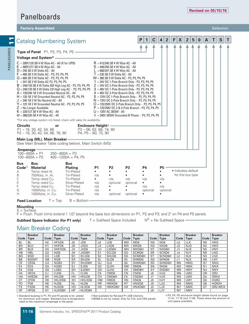
Voltage and System*C = 208Y/120 3Ø 4 W Wye AC - All (X for UPB) R = 415/240 3Ø 4 W Wye AC - AllE = 480Y/277 3Ø 4 W Wye AC - All S = 440/250 3Ø 4 W Wye AC - AllD = 240 3Ø 3 W Delta AC - All L = 600/347 3Ø 4 W Wye AC - AllF = 480 3Ø 3 W Delta AC - P2, P3, P4, P5 T = 230 3Ø 3 W Delta AC - AllG = 600 3Ø 3 W Delta AC - P2, P3, P4, P5 W = 380 3Ø 3 W Delta AC - P2, P3, P4, P5I = 347 3Ø 3 W Delta AC P2, P3, P4, P5 1 = 24V DC 1-Pole Branch Only - P2, P3, P4, P5B = 240/120 3Ø 4 W Delta BØ High Leg AC - P2, P3, P4, P5 2 = 24V DC 2-Pole Branch Only - P2, P3, P4, P5Q = 240/120 3Ø 4 W Delta CØ High Leg AC - P2, P3, P4, P5 3 = 48V DC 1-Pole Branch Only - P2, P3, P4, P5A = 120/240 1Ø 3 W Grounded Neutral AC - All 4 = 48V DC 2-Pole Branch Only - P2, P3, P4, P5H = 120 1Ø 2 W Grounded Neutral AC - P2, P3, P4, P5 5 = 125V DC 1-Pole Branch Only - P2, P3, P4, P5J = 240 1Ø 2 W No Neutral AC - All N = 125V DC 2-Pole Branch Only - P2, P3, P4, P5Y = 125 1Ø 2 W Grounded Neutral AC - P2, P3, P4, P5 O = 125/250V DC 2-Pole Branch Only - P2, P3, P4, P5Z = No Longer Available P = 125/250V DC 2 & 3-Pole Branch - P2, P3, P4, P5K = 220/127 3Ø 4 W Wye AC - All U = 120V AC 3Ø3W - AllM = 380/220 3Ø 4 W Wye AC - All V = 240V 3Ø3W Grounded B Phase - P2, P3, P4, P5
Type of Panel P1, P2, P3, P4, P5
MountingS = SurfaceF = Flush. Flush trims extend 1 1/2" beyond the base box dimensions on P1, P2 and P3; and 2" on P4 and P5 panels.
Circuits or Enclosure Height
P1 – 18, 30, 42, 54, 66 P3 – 56, 62, 68, 74, 80P2 – 18, 30, 42, 54, 66, 78, 90 P4, P5 – 60, 75, 90
Main Lug (ML), Main Breaker(See Main Breaker Table coding below), Main Switch (MS)
Amperage 100–400A = P1 250–800A = P3100–600A = P2 400 –1200A = P4, P5
Standard bussing in P1, P2 and P3 panels is tin- plated for aluminum and copper. Standard bus is temperature rated to the maximum amperage in the panel.
Main Breaker Coding
Catalog Numbering System
*For any voltage system not listed, check with sales for availability.
Subfeed Space Indicator (for P1 only) T = Subfeed Space Included N = No Subfeed Space
Not available for Revised P1 xGB interiors. BQD6 is not UL Listed. Only for CUL and CSA panels
Bus Bus BusCode Material Plating P1 P2 P3 P4 P5A Temp rated Al. Tin-Plated • • • • •B 750A/sq. in. Al. Tin-Plated n/a • • • •C Temp rated Cu. Tin-Plated • n/a n/a n/a n/aE Temp rated Cu. Silver-Plated n/a optional optional • •F Temp rated Cu. Tin-Plated n/a • • n/a n/aG 1000A/sq. in. Cu. Tin-Plated n/a • • optional optionalH 1000A/sq. in. Cu. Silver-Plated n/a optional optional • •
• Indicates default for this bus type.
PanelboardsFactory Assembled Selection�
P 1 C 4 2 F X 2 5 0 A T S T
CodeBreaker Type
N8 HNGN2 HNXN5 HNYN9 LNGN3 LNXN6 LNYN7 NNGN1 NNXN4 NNYQR QR2Q4 QRH2Q5 HQR2Q6 HQR2HQ7 QR2-MCS
CodeBreaker Type
MD MD6MX MXD6MH MXD6HSO SCMD6SQ SCMD6HS5 SHMD6S6 SHMD6HSM SMD6AX SMD6HCN CND6C6 CND6HHN HND6HT HNXD6HX HNXD6H
CodeBreaker Type
L6 LD6LX LXD6LH LXD6HS1 SCLD6S2 SHLD6SL SLD6QJ QJ2Q2 QJ2HQH QJH2C9 CMD6CH CMD6HHM HMD6HR HMXD6HS HMXD6H
CodeBreaker Type
J6 JD6JD JXD2JX JXD6JH JXD6HSC SCJD6SX SHJD6SY SHJD6HSJ SJD6SH SJD6HCL CLD6HH HHLD6XH HHLXD6HL HLD6HO HLXD6HP HLXD6H
CodeBreaker Type
H2 HFXD6H1 HHFD6H3 HHFXD6G2 HGBG3 LGBNB NGBG4 NGB2G5 HGB2G6 LGB2CJ CJD66H HHJD6H9 HHJXD6H6 HJD6H5 HJXD6H7 HJXD6H
CodeBreaker Type
L3 LLKJ2 NJGJ1 NJXJ4 NJYL2 HLKL7 NLKM5 HMGM2 HMXM8 HMYM6 LMGM3 LMXM9 LMYM4 NMGM1 NMXM7 NMY
CodeBreaker Type
BL BLBH BLHBR BLRHB HBLBQ BQDB6 BQD6
CE CED6E4 ED4E6 ED6H4 HED4HA HHED6CF CFD6FD FD6FX FXD6HF HFD6
CodeBreaker Type
ND ND6NX NXD6NT NXD6HSR SCND6ST SCND6HAD SHND6SD SHND6HSN SND6AY SND6HJ6 HJGJ7 HJXJ5 HJYJ9 LJGJ3 LJXJ8 LJY
Revised on 05/15/18
P3, P4, P5 enclosure height tables found on page11-41, 11-70 and 11-85. These show the amount of unit space available.

Siemens Industry, Inc. SPEEDFAX™ 2017 Product Catalog 11-17
11
PAN
ELBO
ARD
S
Type P11) To specify a particular panelboard;
list panel catalog number, branches, modifications, and price on an Estimate Sheet. Price includes interior with provisions, box, ground bar, and trim. See Example No. 1.
2) When more than 66 circuits are specified for P1 a two section panel will be required. Feed-thru lugs must be priced in one section from the modifications on pages 11-24.
Example No. 2 is a two section panel, each having 42 circuits. Section One will contain 1-225/3 QR2 main breaker (top feed), 250A feed-thru lugs and 21" of unit space. Section Two will contain 250A main lugs only (bottom feed) and 21" of unit space. Sections will be 44" in height.
3) Standard main breakers are indicated by the 6th and 7th positions in the catalog number. If any other main breaker type is required, replace with the appropriate code from page 11-16. See Example No. 3.
4) All panel modifications must be listed and priced separately.
5) If the boxes are to be sized the same then each panel must have the same amount of unit space.
Type P2Type P2 panelboards are priced the same as Type P1 described above except for two section panels.
1) When more than 42 circuits are specified for P2, a two section panel will be assumed. Main breaker codes in the 5th and 6th positions will dictate the use of feed-thru lugs. An “ML” in the fifth and sixth positions will dictate the use of subfeed lugs for 125A and 250A and feed-thru lugs for 400A and 600A.
Boxes will be sized the same for two section panels.
Base price includes all provisions. Subfeed or feed-thru lugs as required must be priced separately.
Example No. 4 is a two section panel, each having 42 circuits. Section One will contain 1-400/3 JXD6 main breaker (top feed), 225A feed-thru lugs, and 21" of unit space. Section Two will contain 400A main
lugs only (bottom feed) and 21" of unit space. Sections will be 53" in height.
Types P3, P4 and P51) To specify a particular panelboard,
first determine voltage, system, amperage and type of main, amperage and type of branch devices, and modifications if any. (Step 1)
2) List branch devices and
modifications requiring space additions. List unit space requirements of each.
Note: Some units are twin mounted meaning two breakers occupy the same unit space.
Select appropriate enclosure height from selection chart on pages 11-41, 11-70, or 11-85, based on unit space requirements. (Step 2)
3) Select panelboard catalog number from appropriate table based upon voltage, system, amperage and unit space requirements. (Step 3)
Panel LPA
1 — P1C30QR225ATSN 2540. 10–20/1 25. ea. 250. 4–30/3 140. ea. 560.
3350.
Example No. 1 (pricing not current)
Panel LPB
1 — P1C42QR225ATST 2760. 1 — P1C42ML250ATST 1330. 1 — Feed-Thru Lugs 190.
4280.
Example No. 2 (pricing not current)
Panel LPC
1 — P1C42HF250CTST 3160. HFD6 Main 1900. 42–20/1 BLH 35. ea. 1470. Cu Bus 255. Type 3R 860.
7645.
Example No. 3 (pricing not current)
For inches / millimeters conversion, see Application Data section.
Step #1
Amperage 400Voltage 208Y/120System 3-phase 4-wireMain Main BreakerBranches 5-125/3, 2-225/3, 1-250/3Modification NoneFeed TopMounting Surface
Step #2 Unit Space Calculation
5-125/3 QR2 5" = 15"5-225/3 QR2 5" = 5"1-250/3 FXD6 5" = 5"
25"
Enclosure is B275 from SelectionChart on page 11-48.(32" wide, 75" high, 10" deep).
Step #3
1—P4C75JX400ATS $04210. 5-125/3 QR2 940. 4700. 2-225/3 QR2 940. 1880. 1-250/3 FXD6 2700. 2700. 13490.
NOTE:�This�panel�does�not�require�Subfeed�Space�—�indicated�by�"N"�suffix
NOTE:�This�panel�does�includes�Subfeed�Space�—�indicated�by�"T"�suffix
NOTE:�This�panel�does�includes�Subfeed�Space�—�indicated�by�"T"�suffix
PanelboardsCircuit Breaker / Lighting and Distribution Pricing�
(pricing not current)
Revised on 05/01/17

Siemens Industry, Inc. SPEEDFAX™ 2017 Product Catalog11-18
11
PAN
ELB
OA
RDS
For inches / millimeters conversion, see Application Data section.
Revised Type P1 480Y/277 Vac Maximum 600Y/ 347 Vac Maximum (limited applications) 400 Ampere Mains 400 Ampere Maximum Branch UL Short Circuit Rating — 200,000 A. @ 240 Vac / 100,000 A. @ 480/277 Vac. IR MaximumBranch Breaker Symmetrical Interrupting CapacityBased on Underwriters’ Test ProcedureFeed thru and subfeed lugs may result in lower interrupting ratings if not protected by a main device. Consult sales office.
Meets 2014 NEC wire bending requirement, section 408.55.
Meet Federal Specification W-P-115C.
PanelboardsListed by Underwriters’ Laboratories, Inc., under ”Panelboards” File #E2269 for interiors and #E4016 for boxes and fronts.
Service1-phase 2-wire - 120 Vac, 240 Vac,
1-phase 3-wire - 120/240 Vac,
3-phase 3-wire - 480Y/277 (when derived from 3-phase 4-wire system), 240 Vac, 120 Vac
3-phase 4-wire - 208Y/120 Vac, 480Y/277 Vac, 600Y/347 Vac, 380/220 Vac.
Panelboard Fronts and DoorsStandard panelboards are furnished with trim featuring concealed fasteners and hinges with a flush door lock. All are factory-assembled for ease of installation. Fronts are fabricated from code gauge steel and finished ANSI-61. See page 11-6 for optional fronts.
Main BreakersBL, BLH, HBL, NGB, HGB, LGB, BQD, ED4, ED6, HED4, QR2, QRH2,HQR2, HQR2H, FXD6, FD6, HFD6, HFXD6, JXD6, JD6, HJXD6, HJD6. (All main breakers except 400 amp frame are mounted horizontal.) Note: Revised P1 interiors with BL, BQD or GB Type Mains can be Back-fed in unit space. See special Notes for unit space reduction.
Side Gutter Wiring Space (inches) Panel Reference Panel Width 24" Letter Width 20" (Optional)
A 6.375 7.375
B 5.500 7.500
C 6.125 8.125
D 6.500 8.500
E 5.250 7.250
F 5.000 7.000
Fronts — Surface, Flush (Type 1)20" All #14
Gauge Steel Boxes (Type 1)Width Height Gauge Steel
20" All #16
Main Breaker Panel ConnectorsAmpere Rating Connectors Suitable for Cu or Al
100 (1)—#14 1/0 AWG
125 (1)—#4 1/0 AWG
225 (1)—#4 AWG–300 kcmil
250 (1)—#4/0 AWG–350 kcmil Al (1)—#6/0 AWG–350 kcmil Cu
400 (2)—#3/0 AWG–250 kcmil Al or
(1)—#3/0 AWG–500 kcmil Al
Branch Breaker Side Gutters
P1 400 amp main breaker panels have wire bending space available for 600 kcmil.
400A main breaker is vertical mounted.
Feed-thru lug wire bending space is 15.000" and neutral wire bending space is 15.880" on 400A panel.
P1 panel limited to (1) subfeed 250 amperes max.
See Branch Breaker Side Gutter Chart for Revised P1 Backfed Options.
Main Lug End Gutter Dimensions (inches)
Amp End Neutral Rating Gutter Location
125 10.500 11.500
250 10.500 11.500
400 25.500 26.750
PanelboardsCircuit Breaker / Lighting and Distribution General�
Weight — ApproximateTotal panelboard weight when filled with a normal quantity of breakers and accessories is:
b About 3 lbs. per inch of box height
Series Connected Short Circuit RatingsThe term “Series Connected Short Circuit Rating” refers to the application of series connected circuit breakers in a combination that allows some breakers to have lower individual interrupting ratings than the available fault current. This is permitted as long as the series combination has been tested and certified by UL.
The table below lists specific main and branch breaker series combinations that are marked on all P1 panels. All combinations shown have been tested for use in P1 panelboards and are UL listed. Other combinations are available. See Circuit Breaker Section, of this book.
These series ratings must be specified on order at time of entry.
Connector ranges indicated do not apply to all main breaker types. Refer to molded case circuit breaker standard pressure wire connector chart (Section 7) for the connector range of a specific frame.
Boxes20" wide, 5.75" deep
b End walls are blank as standard.
b End walls with knockouts will be supplied at no charge on 5.75" deep panels if requested at time of order.
Main Lug Connectors125 (1)—#6 AWG–350 kcmil
250 (1)—#6 AWG–350 kcmil
400 std. AL (2) 110-250 kcmil or (1) #2 AWG–600 kcmil
400 opt. CU (2) 1/0–4/0 or (1) 110–600 kcmil
400 opt.AL (1) AL 1/0–750 kcmil (2) AL/CU 250 kcmil max.[max. (1) 600 kcmil (1) wire]
Main Breaker Gutter Dimensions (inches)
MainBreaker
Side Gutter
NeutralLocation
20" w/box
24" w/box
20"w/box
BL, BLH, HBL 8.680 10.690 10.500BQD 7.880 9.880 10.500NGB, LGB, HGB 7.770 9.770 10.500ED4, ED6, HED4 6.125 8.125 10.500QR2, QRH2, HQR2, HQR2H 6.500 8.500 10.500
FD6, FXD6, HFD6, HFDX6 5.250 7.250 10.500
JD6, JXD6 15.000 15.000 26.750
Revised on 04/30/19
Siemens Industry, Inc. SPEEDFAX™ 2017 Product Catalog 11-19
11
PAN
ELBO
ARD
S
Product Category PBSB
PanelboardsCircuit Breaker / Lighting and Distribution Selection�
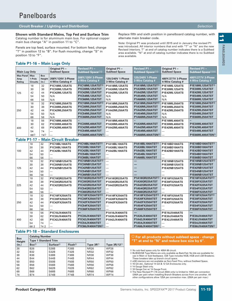
No sub-feed space only for 400A 66 circuit. BL/BQD/GB Type Mains are only available as Back-Fed. No kits are available for
use in Main or Sub-feedspace. (GB Type includes NGB, HGB and LGB Breakers). These breakers take up branch circuit space.
xGB interiors are not available as Non-Feed-Thru, without Subfeed Space. 16 GA std., Optional 14 GA & 12 GA Enclosures only. 14 Gauge Steel only. 16 Gauge Can w/ 14 Gauge Front. The New Revised P1 (18 circuit 250A only) is limited to 100A per connection
(200A per pair) when installing Branch Breakers across from one another. All other configurations allow 125A per connection max. (250A per pair max.)
Table P1-16 – Main Lugs Only
Main Lug OnlyOriginal P1 – Subfeed Space
Revised P1 – Subfeed Space
Original P1 – Subfeed Space
Revised P1 – Subfeed Space
Original P1 – Subfeed Space
Revised P1 – Subfeed Space
Max Panel Amp Rating
Max 1-Pole Circuits
Box Height (in.)
208Y/120V 3-Phase 4-Wire Catalog #
208Y/120V 3-Phase 4-Wire Catalog #
120/240V 1-Phase 3-Wire Catalog #
120/240V 1-Phase 3-Wire Catalog #
480Y/277V 3-Phase 4-Wire Catalog #
480Y/277V 3-Phase 4-Wire Catalog #
125
18 32 P1C18ML125ATS P1C18ML125ATST P1A18ML125ATS P1A18ML125ATST P1E18ML125ATS P1E18ML125ATST
30 38 P1C30ML125ATS P1C30ML125ATST P1A30ML125ATS P1A30ML125ATST P1E30ML125ATS P1E30ML125ATST42 44 P1C42ML125ATS P1C42ML125ATST P1A42ML125ATS P1A42ML125ATST P1E42ML125ATS P1E42ML125ATST54 50 N/A P1C54ML125ATST N/A P1A54ML125ATST N/A P1E54ML125ATST66 56 N/A P1C66ML125ATST N/A P1A66ML125ATST N/A P1E66ML125ATST
250
18 32 P1C18ML250ATS P1C18ML250ATST P1A18ML250ATS P1A18ML250ATST P1E18ML250ATS P1E18ML250ATST
30 38 P1C30ML250ATS P1C30ML250ATST P1A30ML250ATS P1A30ML250ATST P1E30ML250ATS P1E30ML250ATST42 44 P1C42ML250ATS P1C42ML250ATST P1A42ML250ATS P1A42ML250ATST P1E42ML250ATS P1E42ML250ATST54 50 N/A P1C54ML250ATST N/A P1A54ML250ATST N/A P1E54ML250ATST66 56 N/A P1C66ML250ATST N/A P1A66ML250ATST N/A P1E66ML250ATST
400
18 56 P1C18ML400ATS – P1A18ML400ATS – P1E18ML400ATS –30 62 P1C30ML400ATS P1C30ML400ATST P1A30ML400ATS P1A30ML400ATST P1E30ML400ATS P1E30ML400ATST42 68 P1C42ML400ATS P1C42ML400ATST P1A42ML400ATS P1A42ML400ATST P1E42ML400ATS P1E42ML400ATST54 74 — P1C54ML400ATST — P1A54ML400ATST — P1E54ML400ATST
66 74 — P1C66ML400ATSN — P1A66ML400ATSN — P1E66ML400ATSN
Table P1-17 – Main Circuit Breaker
100
18 32 P1C18BL100ATS P1C18BL100ATST P1A18BL100ATS P1A18BL100ATST P1E18BD100ATS P1E18BD100ATST
30 38 P1C30BL100ATS P1C30BL100ATST P1A30BL100ATS P1A30BL100ATST P1E30BD100ATS P1E30BD100ATST42 44 P1C42BL100ATS P1C42BL100ATST P1A42BL100ATS P1A42BL100ATST P1E42BD100ATS P1E42BD100ATST54 50 — P1C54BL100ATST — P1A54BL100ATST — P1E54BD100ATST66 56 — P1C66BL100ATST — P1A66BL100ATST — P1E66BD100ATST
125
18 32 P1C18NB125ATS P1C18NB125ATST — — P1E18NB125ATS P1E18NB125ATST
30 38 P1C30NB125ATS P1C30NB125ATST — — P1E30NB125ATS P1E30NB125ATST42 44 P1C42NB125ATS P1C42NB125ATST — — P1E42NB125ATS P1E42NB125ATST54 50 — P1C54NB125ATST — — — P1E54NB125ATST66 56 — P1C66NB125ATST — — — P1E66NB125ATST
225
18 32 P1C18QR225ATS P1C18QR225ATST P1A18QR225ATS P1A18QR225ATST P1E18FX250ATS P1E18FX225ATST
30 38 P1C30QR225ATS P1C30QR225ATST P1A30QR225ATS P1A30QR225ATST P1E30FX250ATS P1E30FX225ATST42 44 P1C42QR225ATS P1C42QR225ATST P1A42QR225ATS P1A42QR225ATST P1E42FX250ATS P1E42FX225ATST54 50 — P1C54QR225ATST — P1A54QR225ATST — P1E54FX225ATST66 56 — P1C66QR225ATST — P1A66QR225ATST — P1E66FX225ATST
250
18 32 P1C18FX250ATS P1C18FX250ATST P1A18FX250ATS P1A18FX250ATST P1E18FX250ATS P1E18FX250ATST
30 38 P1C30FX250ATS P1C30FX250ATST P1A30FX250ATS P1A30FX250ATST P1E30FX250ATS P1E30FX250ATST42 44 P1C42FX250ATS P1C42FX250ATST P1A42FX250ATS P1A42FX250ATST P1E42FX250ATS P1E42FX250ATST54 50 — P1C54FX250ATST — P1A54FX250ATST — P1E54FX250ATST66 56 — P1C66FX250ATST — P1A66FX250ATST — P1E66FX250ATST
400
18 56 P1C18JX400ATS — P1A18JX400ATS — P1E18JX400ATS —30 62 P1C30JX400ATS P1C30JX400ATST P1A30JX400ATS P1A30JX400ATST P1E30JX400ATS P1E30JX400ATST42 68 P1C42JX400ATS P1C42JX400ATST P1A42JX400ATS P1A42JX400ATST P1E42JX400ATS P1E42JX400ATST54 74 — P1C54JX400ATST — P1A54JX400ATST — P1E54JX400ATST66 2 74 2 — P1C66JX400ATSN — P1A66JX400ATSN — P1E66JX400ATSN
Shown with Standard Mains, Top Fed and Surface Trim Catalog number is for aluminum main bus. For optional copper main bus change “A” in position 11 to “C”.
Panels are top feed, surface mounted. For bottom feed, change“T” in position 12 to “B”. For flush mounting, change “S” in position 13 to “F”.
Replace fifth and sixth position in panelboard catalog number, with alternate main breaker code.
Note: Original P1 was produced until 2015 and in January the revised P1 was introduced. All interior numbers that end with “T” or “N” are the new Revised interiors. T” at end of catalog number indicates there is a Subfeed area available. “N” at end of catalog number indicates there is no Subfeed area available.
Table P1-18 – Standard Enclosures
Box Height (in.)
Catalog Number
Type 1 Standard Trim
Type 3R Type 3R/12Box Surface Flush
26 B26 S26B F26B NR26 WP2632 B32 S32B F32B NR32 WP3238 B38 S38B F38B NR38 WP3844 B44 S44B F44B NR44 WP4450 B50 S50B F50B NR50 WP5056 B56 S56B F56B NR56 WP5662 B62 S62B F62B NR62 WP6268 B68 S68B F68B NR68 WP6874 B74 S74B F74B NR74 WP74
For all products without subfeed space - change “T” at end to “N” and reduce box size by 6”.

Siemens Industry, Inc. SPEEDFAX™ 2017 Product Catalog11-20
11
PAN
ELB
OA
RDS
Product Category PBSB
PanelboardsCircuit Breaker / Lighting and Distribution Selection�
Table P1-3 – Main Breaker Panel Size Selector – Revised P1
Max Ampere rating
Main Breaker Types
Connections suitable for Cu or Al
Max # Poles FT 1
Max # Poles NFT
Dimensions in inches (mm)
Unit SpaceBox Height B
Weight in Lbs. (kg)
FT A
NFT A
100 BL, BLH,HBL, BQD
#8-#6 AWG Cu or Al #8-6 AWG Cu or #8-4 AWG Al #8-#1 AWG Cu or #6-#1/0 AWG Al
18 – 9 26 (661) 90 (41)18 30 9 15 32 (813) 105 (48)30 42 15 21 38 (965) 120 (55)42 54 21 27 44 (1118) 135 (61)54 66 27 33 50 (1270) 150 (67)66 – 33 – 56 (1423) 165 (73)
125
NGB, HGB, LGB
15-30 amp: #14-#6 Cu or #12-#6 Al 35-125 amp: #6-1/0 Cu #4-2/0 Al
18 – 9 26 (661) 95 (43)
ED4
ED6, HED4
#14-#10 AWG Cu or #12-10 AWG Al
#3-3/0 Cu or #1-2/0 Al#3-3/0 Cu or #1-2/0 Al
18 30 9 15 32 (813) 110 (50)30 42 15 21 38 (965) 125 (57)42 54 21 27 44 (1118) 140 (64)54 66 27 33 50 (1270) 155 (71)66 – 33 – 56 (1423) 170 (78)
225 QR2, QRH2, HQR2, HQR2H
#6 AWG-300 Kcmil (Cu) or #4 AWG-300 Kcmil (Al)
18 – 9 26 (661) 95 (43)
18 30 9 15 32 (813) 110 (50)
30 42 15 21 38 (965) 125 (57)
250 FXD6, FD6, HFD6, HFXD6
#6 AWG-350 Kcmil (Cu) or #4 AWG-350 Kcmil (Al)
42 54 21 27 44 (1118) 140 (64)54 66 27 33 50 (1270) 155 (71)66 – 33 – 56 (1423) 170 (78)
400JD6, JXD6, HJD6, HJXD6
3/0-500 Kcmil (Cu) or 4/0-500 Kcmil (Al)
– 30 – 15 56 (1423) 172 (78)30 42 15 21 62 (1575) 190 (86)42 54 21 27 68 (1728) 208 (95)54 66 27 33 74 (1880) 226 (104)
Note: Main breakers use breaker connectors. For sizes, see breaker connector chart. 400A MLO Panels have wire bend space for 600kcmil CU & AL wire when using standard lugs. With optional 750kcmil AL/CU connectors, wire bend space is available for up to 750kcmil AL wire, but is still limited to 600kcmil CU wire.
400A 66 circuit only available with non-feed thru versions. BL, BLH, HBL, BQD, and xGB mount in unit space and count in max. # of poles.
Revised on 04/30/19
Table P1-4 – Main Breaker Selection
Ampere rating
Breaker Types
Max. Ir (kA) at Main Breaker Code Additional Trip Values240 AC 480/277V AC
100
BL (STD) 10 BL 15, 20, 25, 30, 35, 40, 45, 50, 60, 70, 80, 90, 100BLH 22 BH 15, 20, 25, 30, 35, 40, 45, 50, 60, 70, 80, 90, 100HBL 65 HB 15, 20, 25, 30, 35, 40, 45, 50, 60, 70, 80, 90, 100BQD 65 14 BQ 15, 20, 25, 30, 35, 40, 45, 50, 60, 70, 80, 90, 100
125
NGB (STD) 100 25 NB 50, 60, 70, 80, 90, 100, 110, 125HGB 100 35 G2 50, 60, 70, 80, 90, 100, 110, 125LGB 100 65 G3 50, 60, 70, 80, 90, 100, 110, 125ED4 (STD) 65 18 E4 50, 60, 70, 80, 90, 100, 110, 125ED6 (3-pole) 65 25 E6 60, 70, 80, 90, 100, 110, 125HED4 42 42 H4 50, 60, 70, 80, 90, 100, 110, 125
225
QR2 10 QR 100, 110, 125, 150, 175, 200, 225QRH2 25 Q4 100, 110, 125, 150, 175, 200, 225HQR2 65 Q5 100, 110, 125, 150, 175, 200, 225HQR2H 100 Q6 100, 110, 125, 150, 175, 200, 225
250
FXD6 (STD) 65 35 FX 70, 80, 90, 100, 110, 125, 150, 175, 200, 225, 250FD6 65 35 FD 70, 80, 90, 100, 110, 125, 150, 175, 200, 225, 250HFD6 100 65 HF 70, 80, 90, 100, 150, 175, 200, 225, 250HFXD6 100 65 H2 70, 80, 90, 100, 110, 125, 150, 175, 200, 225, 250
400
JXD2 65 – JD 300, 400JXD6 (STD) 65 35 JX 200, 225, 250, 300, 350, 400JD6 65 35 J6 200, 225, 250, 300, 350, 400HJD6 100 65 H6 200, 225, 250, 300, 350, 400HJXD6 100 65 H5 200, 225, 250, 300, 350, 400
xGB�interiors�are�not�available�as�non-feed-thru�without�sub-feed�space. EDC/CED6�2-pole�has�limited�amps�available�(20-50A).

Siemens Industry, Inc. SPEEDFAX™ 2017 Product Catalog 11-21
11
PAN
ELBO
ARD
S
Table P1-5 - Main Lug Panel Size Selector - Revised P1
Maximum Ampere rating
Max # Poles FT
Max # Poles NFT
Dimensions in inches (mm)
MLO Connectors Suitable for
Unit Space
Box Height B"
Weight in Lbs. (kg)
FT A
NFT A
125 (or) 250
18 – 9 26 (661) 90 (41)
(1) #6 AWG - 350 kcmil (CU or AL)
18 30 9 15 32 (813) 105 (48)
30 42 15 21 38 (965) 120 (55)
42 54 21 27 44 (1118) 135 (61)
54 66 27 33 50 (1270) 150 (67)
66 – 33 – 56 (1423) 165 (73)
400
– 30 – 15 56 (1423) 120 (55) AL (2) 1/0 - 250 kcmil or (1) #2 AWG - 600 kcmil CU (2) 1/0 - 4/0 or (1) #2 AWG - 600 kcmil
30 42 15 21 62 (1575) 135 (61)
42 54 21 27 68 (1728) 150 (68)
54 66 27 33 74 (1880) 165 (75)
PanelboardsCircuit Breaker / Lighting and Distribution Selection�
Table P1-6 – Branch Circuit Breakers
Revised P1 Branch Circuit Breakers
1-Pole 2-Pole and 3-Pole
Max IR (kA) at
Amp Ratings Available
Max IR (kA) at
Amp Ratings Available
Amp Rating
Trip Type
Breaker Family
Breaker Type 120V 277V 347V
125V DC
120/ 240V 240V
480Y/ 277V 480V
600Y/ 347V 600V
125/ 250V DC
250V DC
100 Thermal Magnetic
BL BL 10 — — — 15-70 10 10 — — — — — — 15-100
BLH 22 — — — 15-70 22 22 — — — — — — 15-100
HBL 65 — — — 15-50 65 65 — — — — — — 15-100Special Application
BLG BL
BLG 10 — — — 15-20 10 - — — — — — — 30BL(HID) 10 — — — 15-30 10 - — — — — — — 15-30
Thermal Magnetic
BQD BQD (CSA)
BQD 65 14 — 14 15-100 — 65 14 — — — 14 — 15-100BQD6 65 — — 14 15-70 — 65 — 10 — 14 — 15-70
XX Electronic and misc.
BL AFCI/GFCI & Dual Function
X — — — see special table page 11-13
x — — — — — — — see special table page 11-13
125 Thermal Magnetic
GB NGB 100 25 14 14 15-125 — 100 25 — 14 — 14 — 15-125HGB 100 35 14 14 15-125 — 100 35 — 14 — 14 — 15-125LGB 100 65 14 14 15-125 — 100 65 — 14 — 14 — 15-125
3VA41 info not yet available
X X X X X X X — X — — XX X X X X X X — X — — XX X X X X X X — X — — X
Unit space is 1 inch per pole, except for Special Application with accessory included.- No branch kits available, unit space for all branch positions is twin mount. - Branch space is either for BL/BQD only (or) for xGB/3VA41 only. (after 3VA41 is made availabe).
BLG: Two-pole breaker is one phase and neutral. Three pole is two phases and neutral - See SpeedFax Page 7-31 for additional info. Some are Built to order. Allow 2-3 weeks delivery.
Availability and additional specs tbd, expected late 2019. (COMPAS may allow selection of alternate trip units)
110A-125A BL/BLH (2-pole only) available as Main or Subfeed only in Revised P1 panels.
Approved for CSA and UL Listed. Approved for CSA but not UL Listed.
Revised on 04/30/19

Siemens Industry, Inc. SPEEDFAX™ 2017 Product Catalog11-22
11
PAN
ELB
OA
RDS
PanelboardsCircuit Breaker / Lighting and Distribution Selection�
Table P1-7 – Subfeed Breakers (Note: All BL/BQD/xGB Main Strap Kits can also be used for Subfeed.)
Breaker Type
Number of Poles
Max. Interrupting Rating (kA) Available Trip Values240V 480Y/277V
QR2 2, 3 10 – 100, 110, 125, 150, 175, 200, 225QRH2 2, 3 25 – 100, 110, 125, 150, 175, 200, 225HQR2 2, 3 65 – 100, 110, 125, 150, 175, 200, 225HQR2H 2, 3 100 – 100, 110, 125, 150, 175, 200, 225ED4 2, 3 65 18 15, 20, 25, 30, 35, 40, 45, 50, 55, 60, 70, 80, 90, 100, 110, 125ED6 (3-pole) 2, 3 65 25 20, 25, 30, 35, 40, 45, 50, 55, 60, 70, 80, 90, 100, 110, 125HED4 2, 3 100 42 15, 20, 25, 30, 35, 40, 45, 50, 55, 60, 70, 80, 90, 100, 110, 125HHED6 2, 3 100 65 15, 20, 25, 30, 35, 40, 45, 50, 55, 60, 70, 80, 90, 100, 110, 125FXD6 2, 3 65 35 70, 80, 90, 100, 110, 125, 150, 175, 200, 225, 250FD6 2, 3 65 35 70, 80, 90, 100, 110, 125, 150, 175, 200, 225, 250HFD6 2, 3 100 65 70, 80, 90, 100, 110, 125, 150, 175, 200, 225, 250HFXD6 2, 3 100 65 70, 80, 90, 100, 110, 125, 150, 175, 200, 225, 250
Table P1-9 – Lug Kits (Main or Feed-Thru)
Amp Rating Matl.
Wire Range (includes Neutral) Service
Original Catalog Number
Revised P1 Catalog Number
250AL (1) #6 AWG-
350 kcmil (CU or AL)1 Phase MLKA1 MLKA1A3 Phase MLKA3 MLKA3A
CU (1) #6 AWG- 350 kcmil (CU)
1 Phase MLKC1 MLKC1A3 Phase MLKC3 MLKC3A
400AL (2) 1/0 - 250 kcmil
or (1) #2 AWG-600 kcmil1 Phase 4MLKA1 4MLKA1A3 Phase 4MLKA3 4MLKA3A
CU (2) 1/0 - 4/0 or (1) 1/0 - 600 kcmil
1 Phase 4MLKC1 4MLKC1A3 Phase 4MLKC3 4MLKC3A
400 AL
(1) AL 1/0-750 kcmil(2) AL/CU 250kcmil max.[max.(1) 600 kcmil CU wire]
1 Phase — 4MLKA1B
3 Phase — 4MLKA3B
Table P1-10 – Copper Neutral Lug Kits – 250A
No. of Circuits Description
Original P1 Catalog Number
Revised P1 Catalog Number
18
2 or 4 Branch Neutral Strips, 1 Main Neutral Lug, Hardware
CNLK18 Use 30 ckt kit
30 CNLK30 CNLK30A
42 CNLK42 CNLK42A
54, 66 — CNLK54A
Table P1-10A – 2/0 Neutral Lug Kits – 250A and 400A
No. of Circuits Description
Original P1 Catalog Number
Revised P1 Catalog Number
18
2 or 4 Branch Neutral Strips, Hardware
— Use 30 ckt kit
30 — LNLK30A
42 — LNLK42A
54, 66 — LNLK54A
Table P1-11 – 200% Neutral Lug Kits – 250A
No. of Circuits Description
Original P1 Catalog Number
Revised P1 Catalog Number
18
2 or 4 Branch Neutral Strips, 2 Main Neutral Lugs, Hardware
2NLK18 Use 30 ckt kit
30 2NLK30 2NLK30A
42 2NLK42 2NLK42A
54, 66 — 2NLK54A
Table P1-12 – 200% Neutral Lug Kits – 400A
No. of Circuits Description
Original P1 Catalog Number
Revised P1 Catalog Number
18
2 or 4 Branch Neutral Strips, 1 Main 600 kcmil Neutral Lug, Hardware
42NLK18 N/A
30 42NLK30 42NLK30A
42 42NLK42 42NLK42A
54, 66 — 42NLK54A
NOTES: Original P1 kits will not work with Revised P1 interiors if the chart shows different part numbers for each. Revised P1 kits will not work with Original P1 interiors if the chart shows different part numbers for each. Field installable Service Entrance Barrier kits are now available as required by UL67 (In COMPAS, you must
select Service Entrance Required). ED6/CED6 2-pole has limited amps available (20-50A)
Table P1-8 – Breaker Mounting Kit Main or Subfeed Strap Kit w/o Breaker
AmpereRating Breaker Types Service
Original P1 Catalog Number
Revised P1 Catalog Number
100A BL, BLH, HBL 1-Phase MBKBL1 MBKBL1A
3-Phase MBKBL3 MBKBL3A
100A BQD1-Phase
—MBKBC1NBA125A NGB, HGB, LGB MBKNB1
100A BQD3-Phase
MBKBC3MBKBC3NBA125A NGB, HGB, LGB MBKNB3
125A ED4, ED6, HED4, HHED6
1-Phase MBKED1 MBKED1A3-Phase MBKED3 MBKED3A
225A QJ2, QJH2, QJ2H 1-Phase MBKQJ1 MBKQJ1A3-Phase MBKQJ3 MBKQJ3A
225A QR2, QRH2, HQR2, HQR2H
1-Phase MBKQR1 MBKQR1A3-Phase MBKQR3 MBKQR3A
250A FXD6, FD6, HFD6, HFXD6
1-Phase MBKFD1 MBKFD1A3-Phase MBKFD3 MBKFD3A
400A JXD2, JD6, JXD6,HJD6, HJXD6
1-Phase MBKJD1 MBKJD1A
3-Phase MBKJD3 MBKJD3A 400 amp kit is for main only — not allowed for subfeed breaker.��MBKBFA kit is available to mount BL/BQD/xGB 2-pole or 3-pole in unit space as a
"Back-Fed Main". This occupies branch space and reduces circuit count by 2 or 3 posi-tions. (includes Neutral Lug, "MAIN" label and instructions).
��Although QR is rated 250A, it is limited to 225A in panelboard.
Revised on 04/30/19

Siemens Industry, Inc. SPEEDFAX™ 2017 Product Catalog 11-23
11
PAN
ELBO
ARD
S
Table P1-14 – Main Lug End Gutter Dimensions Inches (mm)Amp Rating
End Gutter Neutral Location - to Endwall
20” wide box 24” wide box 20” wide box 24” wide box
125 9.500 (242) 9.500 (242) 10.500 (267) 10.500 (267)
250 9.500 (242) 9.500 (242) 10.500 (267) 10.500 (267)
400 25.500 (648) 25.500 (648) 26.750 (680) 26.750 (680)
NOTE: Feed-thru lug and neutral wire bending space is 15.000” and 16.250” respectively on 400A panel.
Table P1-15 – Side Gutter Wiring Space Inches (mm) (Fig P1-1) Fig P1-1
Reference Letter
Panel Width 20”
Panel Width 24” Optional
A 6.375 (167) 8.375 (213)
B 5.500 (140) 7.500 (191)
C 5.000 (127) 7.000 (178)
D 6.125 (156) 8.125 (206)
E 6.500 (165) 8.500 (216)
F 5.250 (133) 7.250 (184)
Subfeed mounting limit 1 per panel.
For all Revised P1 panels using BL/BQD or xGB breakers as mains in back-fed position, use this chart for wiring space.
Miscellaneous Parts and AccessoriesCatalog # Description
BK1 Bonding Kit for 400A max. Original P1 PanelsBK1A Bonding Kit for 400A max. Revised P1 PanelsBK2 Bonding kit for S1/S2 400 & 600BK3 Bonding kit IMK1 Interior Adjusting KitLPDC01 Directory Card (Pack of 10; ref. 12-1110-01)LPDC02 Directory Card Holder (Pack of 10; ref. 11-1824-01)MCHK Metal Card Holder KitNBK03 Number Strips 1–42. Stick-on type (P1 Panel only)NBK04 Number Strips 43–84. Stick-on type;
Use w/ P1 series PanelsNBK05 Number Strips 85–126. Stick-on type;
Use w/ P1 series PanelsNBK06 Number Strips 127–168. Stick-on type;
Use w/ P1 series PanelsEGK AL Ground Bus 44 ConnectionsECGK CU Ground Bus 44 ConnectionsIGK Insulated AL Ground BusICGK Insulated CU Ground Bus
SEBKRP1V1 FD, QJ, QR Service Entrance Barrier Kit (Revised P1)
SEBKRP1V2 ED Service Entrance Barrier Kit (Revised P1)
SEBKRP1V3 BL/BQD Service Entrance Barrier Kit (Revised P1) back-fed
SEBKRP1V4 xGB Service Entrance Barrier Kit (Revised P1) back-fed
SEBKRP1V5 BL/BQD/xGB Service Entrance Barrier Kit (RP1 in main space)
SEBKP1P2P3V1 JD, LD Service Entrance Barrier Kit (RP1, P1, P2, P3)
EWK1 End Wall Kit with Knockouts (20" W x 5.75" DP)EWK2 End Wall Kit with Knockouts (24" W x 7.75" DP)EBF1 NEB/HEB Filler Plate
P1SCRWS Package of 42 breaker mounting screws for P1DFFP1 1" Branch circuit filler plate (used for BL/BQD/
xGB/xGB2/ED blank positions) (suitable for replacing QF3 in P1 thru P5 Panelboards and Switchboards)
P1CONBPHCU Connector kit – 6 pcs. B-phase CopperP1CONBPHAL Connector kit – 6 pcs. B-phase AluminumP1CONACPHCU Connector kit – 6 pcs. A or C-phase Copper
MBKQRFK P1/Revised P1 Filler for 1PH/3PH QR. Horizontal mount only.
ANSI/NEMA PB 1.1-2013
General Instructions for Proper Installation, Operation, and Maintenance of Panelboards Rated 600 Volts or Less (O&M Manual)
Replacement parts only. PDF can be downloaded (at no cost) and printed at:
www.nema.org/standards/pages/Panelboards.aspx Factory installed and Field installable Service Entrance
Barrier kits are now available as required by UL67. (In COMPAS, you must select Service Entrance Required.)
Use for both CU + AL bus interiors.
Panel Width20 in. (508 mm)
Feed-Thru (FT) Non-Feed-Thru (NFT) Example of Back-fed xGB Main breaker installed
Table P1-13 – Main Breaker Gutter Dimensions Inches (mm)
Main Breaker
Gutter SpaceNeutral Locationto Endwall
20” wide box 24” wide box 20” wide box
BL, BLH, HBL 8.680 (220) 10.690 (272) 10.500 (267)
BQD 7.880 (200) 9.880 (251) 10.500 (267)
NGB, HGB, LGB 7.770 (197) 9.770 (248) 10.500 (267)
ED4, ED6, HED4 6.125 (156) 8.125 (206) 10.500 (267)
QR2, QRH2, HQR2, HQR2H 6.500 (165) 8.500 (216) 10.500 (267)
FD6, FXD6, HFD6, HFXD6 5.250 (133) 7.250 (184) 10.500 (267)
JD6, JXD6 15.000 (381) 15.000 (381) 26.500 (674)
JD frame mounted vertically.
For Revised P1 with Back-fed Main option, use Side Gutter Wiring Spec Table P1-15.
These dimensions are for Revised P1 only. See Original P1 cut sheets for valid dimensions if needed (P1 production prior to January 2015).
PanelboardsCircuit Breaker / Lighting and Distribution Selection�
Revised on 04/30/19

Siemens Industry, Inc. SPEEDFAX™ 2017 Product Catalog11-24
11
PAN
ELB
OA
RDS
Product Category PBSB
PanelboardsType P1 Panelboard Modifications and Additions Selection�
Panel OptionsEnclosures• Extra gutter to sides or ends of the can• 24” wide boxes• Hinged to box trim• Door-in-door trims• Screw to box trims • Piano hinge trims• Painted boxes (ANSI 61 Light Gray is standard color)• Custom colors• Increase gauge trims and boxes (See pages 12-13)• Stainless steel trims (304 SS only) for Type 1 enclosures• Type 1 enclosures (Std 16 Gage / Optional 14 or 12 Gage)• Type 1 Standard are A60 Galvanealed non painted (Painted Type 1
use HRPO material)• NEMA 3R/12 enclosures 16 Gauge Can w/ 14 Gauge front)• NEMA 4 enclosures (14 Gauge only)
Panel Modifications• Main Bus Standard main bus is tin-plated aluminum. For copper main
bus, add from the table for each panel. Includes copper neutral cross bar. For copper neutral branch lugs, see miscellaneous.
• Compression lug for MLO
• Contactor mains - Mount in 23” enclosure ahead of panel. – Asco 920 through 225 amps
– Asco 911 through 150 amps
– Siemens LEN through 30 amps
• Branch and main breaker accessories – Handle blocks – Handle locks• Feed-thru lugs
Cannot be used in conjunction with SPD/TVSS or subfeed breakers. Do not add height to the panel.
Feed-thru LugsAmp Rating Type
Connector CU/AL Range
250
AL/CU Mechanical
(1)–#6 AWG- 350 kcmil
CU Mechanical
(1)–#6 AWG- 350 kcmil
AL/CU Compression
(1)–#6 AWG- 350 kcmil
400
AL/CU AWG Mechanical
(2)–#1/0 - 250 kcmil or
(1)–#2 AWG- 600 kcmil
CU (1)–1/0-600 kcmil (2)-1/0-4/0
AL/CU Compression
(1) 400-600 kcmil AL (1) 400-500 kcmil CU
• 200% neutral
• Copper lugs, mechanical line and branch neutral
• Bus mounted SPD/TVSS
• Service entrance labeling• Factory installed and Field installable Service Entrance Barrier
kits are now available as required by UL67• Grounding of Panelboards
Ground Bars except for brazed to box are shipped with the panel interior.
– Non-Insulated Equipment Ground Bar – standard – Copper Non-Insulated Ground Bar – optional – AL Insulated Equipment Ground Bar – optional – CU Insulated Equipment Ground Bar – optional – Ground Bar Brazed to Box (recommended for painted boxes)• Shunt Trip on Main or Branch
BL, BLH, HBL, BQD, xGB as branch use 1” unit space for shunt trip.
QR2, QRH2, HQR2, HQR2H, ED2, ED4, ED6, HED4, HED6, HHED6, FD6, FXD6, HFD6
HFXD6, JXD6, JD6, HJD6, HJXD6
• Remote control switches – 480V AC max. mounted ina 23” enclosure to be cable connected to the panel.
• Time Clocks – mounted in a 23” enclosure to be cable connected to the panel. Tork time clock can be supplied and mounted in panelboard cabinet.Time Clock Information and Options
Time Clock (1- or 2-Pole, Single or Double Throw Contacts, 3-Pole Single Throw) 277V Maximum with Plain DialOptions:
Astronomical Dial
An Omitting Device
Reserve Power or Carryover
Space and Mounting Provisions Only
• NEMA 4X enclosures (14 Gauge only - 304SS Std, 316SS Optional)
• Special Keyed Locks (Keys are not supplied)• Panel skirts• Gaskets between trim and box
TEY TEU1 Cat 60 LL803 LL806
All fit FAS-Latch Front*
Yale 47 (NYC)National C413ABeck Lock 7-pin tumblerSouthco 1 4 FastenerCorbin 1001 FAB7
Special non-FAS-Latch*
*See�page�11-7�for�more�information.
Note: Specify copper or aluminum cable.
Do not increase panel or enclosure size. Accessories on 1” pole breakers (BL, BQD, xGB, ED) will take 1” unit space. External to the panel, supplied in a separate enclosure.
Revised on 04/30/19

Siemens Industry, Inc. SPEEDFAX™ 2017 Product Catalog 11-25
11
PAN
ELBO
ARD
S
Product Category PBSB
PanelboardsType P1 Panelboard Modifications and Additions Selection�
Enclosure ModificationsCompression Lugs
Remote Switch Modifications
Table P1-19 – Lugs
StyleAmp Rating
Breaker Type
Compression Connectors
Box Height Addition
MLO
125N/A (1) #6 AWG - 350 kcmil None
250
400 N/A (1) 400 - 600 kcmil AL (1) 400 - 500 kcmil CU None
Main Breaker
125 ED4, ED6, HED4 (1) #14 AWG - 2/0 Box must go to 24” wide
225 QR2, QRH2, HQR2, HQR2H
(1) #6 AWG - 350 kcmil CU or AL Box must go to 24” wide
250 FXD6, HFD6 (1) #6 AWG - 350 kcmil CU or AL Box must go to 24” wide
Note: Standard compression lugs used for P1 panels are range taking lugs and require a particular crimping tool (tool is Hubbell/Anderson Versa Crimp VC6 -for 250A) to accommodate the range. Consult factory for information. 200% neutral not available with compression lugs. xGB breakers cannot accommodate compression lugs. (For 400A tool use Hubbell/Anderson Versa Crimp VC6FT/VC7FT - see instruction sheet for details.)
NEMA-4–Water Tight, Dust Tight, Steel Enclosure (Actual NEMA-4 enclosure is larger than standard Type 1 enclosure. See chart below for reference to approximate actual size.)
Table P1-20
Standard Box Height (in inches)
Actual NEMA 4 Enclosure Size
H W D
32 32 20 838 42 30 844 48 36 856 60 36 10
Note: Larger NEMA 4 enclosures are not available.
Table P1-22 – Control Power TransformerSize VA Relay
0, 1 50
2 75
3 150
4 250
Table P1-24 – Remote Control Switch ModificationDescription
Auxiliary Contacts (mounted, not wired)
2-Wire Control
Table P1-23 – Applications for a Remote SwitchSwitch Type Modification
920 Mounts in 23” relay cabinet as a main only
LEN 30A mounts in 23” relay cabinet as a main only
Gauge Steel of Boxes/Fronts, Surface and Flush (see pgs. 11-6 & 11-7)Dimensions in Inches (mm) Gauge Steel
H W Box Front/Door Type
26-74 (660-1880) 20 (508) 16 14 Type 126-74 (660-1880) 20 (508) 16 16/14 Type 3R/1232-60 (813-1524) 20-36 (508-914) 14 14 Type 426-74 (660-1879) 20 (508) 14 14 Type 4X36-60 (914-1524) 30-36 (762-914) N/A N/A Type 4X Non-Metallic
16 Gauge is Standard (14 Gauge & 12 Gauge are optional) 15 Gauge Steel Can with 14 Gauge Door or Similar Approved Construction No Optional Gauge available 304SS 14 Gauge Std., 316SS 14 Gauge optional Sizes do not match Standard Enclosure Sizes - See Table P1-21 - material is non-metallic - No Gauge Specified. FAS-Latch is 14 GA only. Screw-to-Box, Hinge-to-Box, Door-in-Door (14 GA Std./12 GA Std. or 10 GA Optional)
STB/HTB/DND with Piano Hinge (14 GA Std./12 GA Optional) (14 GA Stainless 304 Optional)
Revised on 04/30/19
Table P1-21 – NEMA Type 4X (Water Tight, Dust Tight and Corrosion Resistant)
Enclosure – Stainless Steel (304SS is standard)Note: 316SS is optional - must be specified
Enclosure – Non-metalic / Fiberglass
Catalog Number
Size (inches)Catalog Number
Size (inches)Catalog Number
Ref. Interior Height
Size (inches) Custom order in COMPAS Reference NumberH W D H W D H W D
B4X26 26 20 5.75 24B4X26 26 24 5.75 tbd 26 30 24 8 A30H2408GQRLPB4X32 32 20 5.75 24B4X32 32 24 5.75 tbd 32 36 30 8 A36H3008GQRLPB4X38 38 20 5.75 24B4X38 38 24 5.75 tbd 38
48 36 12 A48H3612GQRLPB4X44 44 20 5.75 24B4X44 44 24 5.75 tbd 44B4X50 50 20 5.75 24B4X50 50 24 5.75 tbd 50
60 36 12 A60H3612GQRLPB4X56 56 20 5.75 24B4X56 56 24 5.75 tbd 56B4X62 62 20 5.75 24B4X62 62 24 5.75 tbd 62 na na na naB4X68 68 20 5.75 24B4X68 68 24 5.75 tbd 68 na na na naB4X74 74 20 5.75 24B4X74 74 24 5.75 tbd 74 na na na na

Siemens Industry, Inc. SPEEDFAX™ 2017 Product Catalog11-26
11
PAN
ELB
OA
RDS
PanelboardsType P1 Enclosure Details Dimensions�
20 in.[ 508 ]
5.75 in.[ 146 ]
³⁄₄ in.[19 ]
³⁄₄ in.[19 ]
Type 1 BoxBox is symmetrical
0.313 in. Dia.
(Mounting Holes0.437 in. Square)
(Mounting Holes0.437 in. Square)
8.0 in.[ 204 ]
23.0 in.[ 584 ]
(Mounting Holes0.437 in. Square)
(Mounting Holes0.437 in. Square)
0.313 in. Dia.
(Mounting Holes0.437 in. Square)
(Mounting Holes0.437 in. Square)
8.0 in.[ 204 ]
23.0 in.[ 584 ]
(Mounting Holes0.437 in. Square)
(Mounting Holes0.437 in. Square)
Dimensions are interior of the box. Add 5/8” to width for absolute dimension. Add 1/8” to height for absolute dimension.
Dimensions shown in inches and millimeters [ ].
Type 3R and 3R/12 BoxFlush�Mounting
(UL approved construction. 16 Gage Steel or equivalent alternate Construction. 14 or 12 Gage is available as an optional special order.)G60 Galvanized is standard without paint.
(UL approved construction. 16 Gage Steel Can with 14 Gage front or similar approved construction.)
A60 Galvannealed with ANSI 61 light gray paint is standard.
Revised on 04/30/19

Siemens Industry, Inc. SPEEDFAX™ 2017 Product Catalog 11-27
11
PAN
ELBO
ARD
S
PanelboardsType P2 Panelboards General�
Gauge Steel of Boxes/Fronts, Surface and Flush (see pgs. 11-6 & 11-7)Dimensions in Inches (mm) Gauge Steel
H W Box Front/Door Type
26-74 (660-1880) 20 (508) 16 14 Type 126-74 (660-1880) 20 (508) 16 16/14 Type 3R/1232-60 (813-1524) 20-36 (508-914) 14 14 Type 426-74 (660-1879) 20 (508) 14 14 Type 4X36-60 (914-1524) 30-36 (762-914) N/A N/A Type 4X Non-Metallic
16 Gauge is Standard (14 Gauge & 12 Gauge are optional) 15 Gauge Steel Can with 14 Gauge Door or Similar Approved Construction No Optional Gauge available 304SS 14 Gauge Std., 316SS 14 Gauge optional Sizes do not match Standard Enclosure Sizes - See Table P1-21 - material is non-metallic - No Gauge Specified. FAS-Latch is 14 GA only.
Screw-to-Box, Hinge-to-Box, Door-in-Door (14 GA Std./12 GA Std. or 10 GA Optional) STB/HTB/DND with Piano Hinge (14 GA Std./12 GA Optional)
Revised on 04/30/19
FeaturesFlexibility is the hallmark of the P2 panel. This panel offers a wide array of factory-assembled options to meet almost all lighting panel applications. With this design, the ability to mix breaker frames in unit space up to 250 amps will also meet many distribution panel requirements in a much smaller package. Bussing options for the P2 vary from the typical temperature rated to 750 A/Si aluminum to 1000A/Si copper. Standard bussing in the P2 panel is tin-plated. Silver-plated copper is also offered as an option. Integrated time clocks, bus mounted contactors, as mains or sub mains, split bus, and subfeed lugs (up to 400 amp) are just a few of the options of this unique panel.
Like a lighting panel, P2 is set up around 18, 30, 42, 54, 66, 78, and 90 circuit configurations. It will also allow the user to configure the panel to the smallest possible size. The P2 panel starts with 9" of unit space (18 circuits of 1" pole breakers). Breakers mounted in unit space can be mixed and matched to meet customer requirements. All 1" pole breakers (BL, BQD, xGB, xGB2, ED frames) are mounted in 3" or 6" pole increments. Breaker frames, above 125 amps, are mounted in 6" single breaker mountings.
As an example of a minimum panel, (6) 20 amp 1-pole BL breakers (3" of unit space) and a 3-pole 225 amp QJ breaker (6" of unit space) equaling 9" of unit space can be configured in a P2 panel without any extra provisions or space required. FD 250 amp and JD 400 amp breakers are mounted as subfeed breakers outside of unit space.
Another unique feature of the P2 panel is that blank unit space can be added to allow for future expansions or modifications. Any expansions or modifications must be in 3" increments. BL, BQD, xGB, xGB2, and ED frame breakers have 3" or 6" pole kits, and can be mixed in unit space by these increments. Breakers of the same frame can cross from one mounting to another if contiguous. QR frame breakers are mounted in 6" increments for two- and three pole, single mounted units. Changes in the unit space length for BL, BQD, xGB, xGB2, or ED frame breakers require an addition deadfront, center strip kit. Check with sales or the factory for additional unit space kits.
Main Lug / Main BreakerEnclosure – Standard Type 1 enclosure is 20" wide x 5.75" deep X. Box Height is determined by main device and unit space. See charts for box height.
Voltage – 600V AC max. 250V DC max.
Amperage – 600 amp max.
Short circuit rating – 200 KAIC max. symmetrical or equal to the lowest rated device installed unless a series rating is indicated. Panels with subfeed or feed-thru lugs without a main device, circuit breaker or fusible unit, are limited to a three-cycle rating. The three-cycle rating for the P2 panel is limited to 22 KAIC. Note that the main device may be mounted remote from the panel.
Bussing – The P2 panel has more options to meet market requirements. The standard bussing is temperature rated aluminum. The rating is per the requirements of UL 67 – the standard for panelboards. All aluminum bussing is tin-plated. Optional bussing for the P2 panel is: 750 A/Si aluminum, temperature rated copper, and 1000 A/Si copper. The copper bus option for this panel is tin-plated.
Weight – ApproximateTotal panelboard weight when filled with a normal quantity of breakers and accessories is about 3 lbs. (1 kg) per inch (54g per mm) of box height.

Siemens Industry, Inc. SPEEDFAX™ 2017 Product Catalog11-28
11
PAN
ELB
OA
RDS
Box depth = 5.75 in. (146 mm) Box width = 20 in. (508 mm) for 100-600A
Box depth = 5.75 in. (146 mm) Box width = 20 in. (508 mm) for 100-600A
Main lug wire bending space diagram
Main breaker wire bending space diagram
“B” Dimen-sion Box Height
P2 Panels with Standard Line Lugs. Unit Space (starting with 9" and adding 6" increments) “A” Dimension
Main Lugs Main Breakers
125A 250A400A 600A
125A Horiz. BL, BQD, xGB, ED
125A Vert. ED
125A Horiz. CED
225A Horiz. QR
225A Vert. QR
250A Horiz. FD
250A Vert. FD
250AVert.CFD
400AVert. JD
400AVert. CJD
600AVert. LD
600AVert. CLD
26 9 — — 9 — — — — — — — — — — —32 15 9 — 15 9 9 9 — — — — — — — —38 21 15 9 21 15 15 15 9 9 — — — — — —44 27 21 15 27 21 21 21 15 15 9 — — — — —50 33 27 21 33 27 27 27 21 21 15 9 9 — — —56 39 33 27 39 33 33 33 27 27 21 15 15 — 9 —62 45 39 33 45 39 39 39 33 33 27 21 21 9 15 968 45 45 39 45 45 45 45 39 39 33 27 27 15 21 1574 45 45 45 45 45 45 45 45 45 39 33 33 21 27 21
[54p] [54p] [54p] [54p] [54p] [54p] [54p] [54p] [54p] [54p] [54p] [54p] [42p] [54p] [42p]
“B” Dimen-sion Box Height
P2 Panels with Standard Line Lugs. Unit Space (starting with 9" and adding 6" increments) “A” Dimension
Main Lugs Main Breakers
125A 250A400A 600A
125A Horiz. BL, BQD, xGB, ED
125A Vert. ED
125A Horiz. CED
225A Horiz. QR
225A Vert. QR
250A Horiz. FD
250A Vert. FD
250AVert. CFD
400AVert. JD
400AVert. CJD
600AVert. LD
600AVert. CLD
56 33 — — 33 — — 33 — — — n/a — n/a n/a n/a62 39 33 33 39 33 33 39 33 — — n/a — n/a n/a n/a68 45 39 39 45 39 39 45 39 33 — n/a — n/a n/a n/a74 45 45 45 45 45 45 45 45 39 33 n/a 33 n/a n/a n/a
[90p] [90p] [90p] [90p] [90p] [90p] [90p] [90p] [78p] [66p] n/a [66p] n/a n/a n/a Note: The vertical main breaker application for ED, QJ, QR, and FD adds 6" of box height.
PanelboardsType P2 Panelboards Selection/Dimensions�
Revised on 04/30/19
Table below shows minimum Box Size required for the Unit Space indicated with the Main Option at the top of each Column. n Adding other options generally will
add to the box Height when config-ured in COMPAS. Also, there may be cost adders with each option.
n The maximum number of 1" circuits supported is show at the bottom of each column in brackets. [54p] = max 54 poles of 1" circuits supported (BL, BQD, ED, xGB, xGB2).
n Unit space is available in 9", 15", 21", 27", 33", 39", and 45" sizes.
n Within unit space listed, the neutral
will support up to 54 circuits. n When more then 54 circuits are
required, COMPAS will configure with larger Extended Circuit Neutral - see Extended Circuit chart below for mini-mum box sizes.
n Box sizes available: 26", 32", 38", 44", 50", 62", 68", 74"
When COMPAS configuration has more than 54 circuits, the large neutral configuration is needed. Box size shown is the minimum available without any options.
n Unit space of 33", 39", and 45" are available.
n Unit space will be reduced by selecting some options such as Feed-thru lugs, Surge Protection Devices, and the other Subfeed options.
n In general, vertically mounted mains require 6" more box space than equivalent horizontally mounted mains.
n Neutral configuration supports a maximum of 90 1-pole breakers.
Standard Circuit P2 Panels (Neutral Configurations for up to 54 circuits max.)
Extended Circuit P2 Panels (Neutral Configurations for more than 54 circuits)

Siemens Industry, Inc. SPEEDFAX™ 2017 Product Catalog 11-29
11
PAN
ELBO
ARD
S
Refer to diagrams at the bottom of page 11-28. Single branch mounting construction.
Branch Breaker Side Gutters Inches (mm)
A 5.750 (146)B 5.125 (130)C 4.000 (102)D 5.000 (127)E 4.625 (117)
ReferenceLetter Panel Width 20" (508)
Main Breaker Wire Bending
Standard Circuits (up to 54 1" module branch poles)
Panel Amps Breaker Frames C D
100BL 5.75 8.00BQD 5.13 8.00
125xGB, xGB2 4.63 8.00ED (horiz.) 4.00 8.00ED (vert.) 6.56 11.13
225QR (horiz.) 5.00 7.00QR (vert.) 10.06 16.69
250FD (horiz.) 5.00 7.00FD (vert.) 13.25 22.72
400 JD 15.38 25.00600 LD 15.38 23.00
Main Breaker Wire Bending
Extended Circuits (more than 54 1" module branch poles)
Panel Amps Breaker Frames C D
100BL 5.75 6.56BQD 5.13 6.56
125xGB, xGB2 4.63 6.56ED (horiz.) 4.00 6.56ED (vert.) 12.56 14.88
225QR (horiz.) 5.00 6.44QR (vert.) 10.06 15.53
250FD (horiz.) 5.00 5.63FD (vert.) 19.25 25.71
400 JD 15.38 23.75600 LD (54p max) N/A N/A
Main Lug Connectors
Standard Circuits (up to 54 1" module branch poles)
Panel Amps Standard Connectors C D
125 (1) #14-2/0 6.62 8.19250 (1) #6 AWG - 350 MCM 11.75 10.72
400 (1) #4 AWG - 600 MCM or (2) #6 - 250 MCM
14.00 13.09
600 (2) #4 AWG - 500 MCM 14.00 11.00
Main Lug Connectors
Extended Circuits (more than 54 1" module branch poles)
Panel Amps Standard Connectors C D
125 (1) #14-2/0 12.62 8.91250 (1) #6 AWG - 350 MCM 17.75 13.69
400 (1) #4 AWG - 600 MCM or (2) #6 - 250 MCM
14.00 14.19
600 (2) #4 AWG - 500 MCM 14.00 14.23
Standard Circuit P2 Panels Extended Circuit P2 Panels
PanelboardsType P2 Panelboards Selection/Dimensions�
Panel Width20 in. (508 mm)
BL, BLH, HBL BL, BLH, HBL BLF2, BLHF2, BLF2, BLHF2, HBLF2, BLFB, BLHFB HBLF2, BLFB, BLHFB BQD, BQD6 BQD, BQD6
ED4, ED6 ED4, ED6 HED4, HHED6 HED4, HHED6
QR2, QRH2, HQR2, HQR2H(Single Mounted)
NGB, HGB, LGB NGB, HGB, LGB NGB2, HGB2, LGB2 NGB2, HGB2, LGB2
A A
B B
C C
E E
D
Revised on 05/15/18
BQD6 is not UL Listed. Only for CUL and CSA panels.
D

Siemens Industry, Inc. SPEEDFAX™ 2017 Product Catalog11-30
11
PAN
ELB
OA
RDS
�Interchangeable trip main breakers are mounted at top of panel only.
�Vertically mounted.
Subfeed Breakers (available in 2-pole or 3-pole)
BreakerType
Mounting Position When Used as Subfeed Breaker
AmpereRatingsFor Load
Maximum Interrupting Rating(kA) Symmetrical
Vertical 240V AC 480V AC 600V AC
FD6, FXD6 Twin 70–250 65 35 22HFD6, HFXD6 Twin 70–250 100 65 25JD6, JXD6 Single 200–400 65 35 25HJD6, HJXD6 Single 200–400 100 65 35
Vertically Mounted Main Breaker (available in 2-pole or 3-pole)
Ampere Rating Breaker Type(s)Additional Unit Space (in.)
125 ED4, ED6, HED4, HHED6 6
225 QR2, QRH2, HQR2, HQR2H 6
250 FXD6, FD6, HFD6 6
PanelboardsType P2 Panelboards Selection�
Product Category UNPB
Main Breaker Selection
AmpRating
BreakerType
Max. Interrupting Rating (kA) Ref.Type Code
Horizontalor Vertical Available Trip Values240V 480V 600V
100
BL 10 — — BL H 15, 20, 25, 30, 35, 40, 50, 60, 70, 80, 90, 100HBL 65 — — HB H 15, 20, 25, 30, 35, 40, 50, 60, 70, 80, 90, 100BQD 65 14 — BQ H 15, 20, 25, 30, 35, 40, 50, 60, 70, 80, 90, 100BLH 22 — — BH H 15, 20, 25, 30, 35, 40, 50, 60, 70, 80, 90, 100
125
NGB 100 25 14 NB H 50, 60, 70, 80, 90, 100, 110, 125HGB 100 35 14 G2 H 50, 60, 70, 80, 90, 100, 110, 125LGB 100 65 14 G3 H 50, 60, 70, 80, 90, 100, 110, 125ED4 65 18 — E4 H/V 50, 60, 70, 80, 90, 100, 110, 125ED6 100 25 14 E6 H/V 60, 70, 80, 90, 100, 110, 125 (3-pole)HED4 100 42 — H4 H/V 50, 60, 70, 80, 90, 100, 110, 125CED6 200 200 100 CE H/V 50, 60, 70, 80, 90, 100, 110, 125NGB2 100 25 14 G4 H 50, 60, 70, 80, 90, 100, 110, 125HGB2 100 35 22 G5 H 50, 60, 70, 80, 90, 100, 110, 125LGB2 100 65 25 G6 H 50, 60, 70, 80, 90, 100, 110, 125
225
QR2 10 — — QR H 100, 110, 125, 150, 175, 200, 225QRH2 25 — — Q4 H 100, 110, 125, 150, 175, 200, 225HQR2 65 — — Q5 H 100, 110, 125, 150, 175, 200, 225HQR2H 100 — — Q6 H 100, 110, 125, 150, 175, 200, 225FD6 65 35 18 FD H/V 70, 80, 90, 100, 110, 125, 150, 175, 200, 225FXD6 65 35 18 FX H/V 70, 80, 90, 100, 110, 125, 150, 175, 200, 225HFD6 100 65 25 HF H/V 70, 80, 90, 100, 110, 125, 150, 175, 200, 225HFXD6 100 65 25 H2 H/V 70, 80, 90, 100, 110, 125, 150, 175, 200, 225CFD6 200 200 100 CF H/V 70, 80, 90, 100, 110, 125, 150, 175, 200, 225
250
FD6 65 35 18 FD H/V 70, 80, 90, 100, 110, 125, 150, 175, 200, 225, 250FXD6 65 35 18 FX H/V 70, 80, 90, 100, 110, 125, 150, 175, 200, 225, 250HFD6 100 65 35 HF H/V 70, 80, 90, 100, 110, 125, 150, 175, 200, 225, 250HFXD6 65 35 25 H2 H/V 70, 80, 90, 100, 110, 125, 150, 175, 200, 225, 250
400
JXD6 65 35 25 JX V 200, 225, 250, 300, 350, 400JD6 65 35 35 J6 V 200, 225, 250, 300, 350, 400HJXD6 100 65 35 H6 V 200, 225, 250, 300, 350, 400HJD6 100 65 35 H5 V 200, 225, 250, 300, 350, 400SJD6 65 35 25 SJ V 200, 300, 400SHJD6 100 65 35 S2 V 200, 300, 400CJD6 200 200 100 CJ V 200, 300, 400SCJD6 200 200 100 SC V 200, 300, 400
600
LXD6 65 35 25 LX V 450, 500, 600LD6 65 35 25 L6 V 250, 300, 350, 400, 450, 500, 600HLXD6 100 65 35 HL V 250, 300, 350, 400, 450, 500, 600HLD6 100 65 35 HO V 250, 300, 350, 400, 450, 500, 600SLD6 65 35 25 SL V 300, 400, 500, 600SHLD6 100 65 35 S6 V 300, 400, 500, 600CLD6 200 150 100 CL V 300, 400, 500, 600SCLD6 200 150 100 C6 V 300, 400, 500, 600
When an ED4, ED6, HED4, HHED6, QR2, QRH2, HQR2, HQR2H, FD6, HFD6, or FXD6 frame main breaker is required to be vertically mounted, pricing will typically be higher.
��Twin mounted subfeed breakers are mounted at the bottom of panelboard only and adds 24" to the panel height.
�� Subfeed breaker is mounted at bottom of panelboard only. 400 amp subfeed breaker adds 24" to the panel height. (Only for use with MLO)
�� ED6/CED6 2-pole limited amps available (20-50A)
Revised on 04/30/19

Siemens Industry, Inc. SPEEDFAX™ 2017 Product Catalog 11-31
11
PAN
ELBO
ARD
S
#14-#6 26 65#14-1/0 28 125#6-350 kcmil 3 250(1) #4-600 kcmil 1 400or (2) #6-250 kcmil
Wire Range Max. Number of Connections Max. Amp
Branch Neutral Connections
PanelboardsType P2 Panelboards Selection�
Product Category PBSB
Revised on 04/30/19
P2 Branch Circuit Breakers S = Single Mount
1-Pole 2-Pole and 3-Pole
S
T = Twin mount
Amp Rating
Trip Type
Breaker Family
Breaker Type
Max IR (kA) at
Amp Ratings Avail.
Max IR (kA) at
Amp Ratings Avail. T
Unit Space per Kit (in.)
Max 1-pole Circuits per Kit120V 277V 347V
125V DC
120/240V 240V
480Y/277V 480V
600Y/347V 600V
125/250V DC
250V DC
100
Thermal Magnetic BL
BL 10 — — — 15-70 10 10 — — — — — — 15-100 — T 3.00 6BLH 22 — — — 15-70 22 22 — — — — — — 15-100 — T 3.00 6HBL 65 — — — 15-50 65 65 — — — — — — 15-100 — T 3.00 6
Special Application
BLG BL
BLG 10 — — — 15-20 10 — — — — — — — 30 — T 3.00 6BL (HID) 10 — — — 15-30 10 — — — — — — — 15-30 — T 3.00 6
Thermal Magnetic BQD
BQD 65 14 — 14 15-100 — 65 14 — — — 14 — 15-100 — T 3.00 6BQD6 65 — — 14 15-70 — 65 — 10 — 14 — 15-70 — T 3.00 6
xx Electronic and misc. BL
AFCI/GFCI & Dual Function
x — — —
see special table page 11-13
x — — — — — — —
see special table page 11-13
— T 3.00 6
125 Thermal Magnetic
GBNGB 100 25 14 14 15-125 — 100 25 — 14 — 14 — 15-125 — T 3.00 6HGB 100 35 14 14 15-125 — 100 35 — 14 — 14 — 15-125 — T 3.00 6LGB 100 65 14 14 15-125 — 100 65 — 14 — 14 — 15-125 — T 3.00 6
Sentron
ED4 65 22 — 30 15-100 — 65 — 18 — — — 30 15-125 — T 3.00 6ED6 — — — 15-100 — 65 — 25 — 18 — 30 20-125 — T 3.00 6HED4 100 25 — 30 15-100 — 65 — 18 — — — 30 15-125 — T 3.00 6HHED6 — — — — — — 100 — 65 — 18 — — 15-50 — T 3.00 6
GB2NGB2 100 25 14 14 15-125 — 100 — 25 14 — 14 — 15-125 — T 3.00 6HGB2 100 35 22 14 15-125 — 100 — 35 22 — 14 — 15-125 — T 3.00 6LGB2 100 65 25 14 15-125 — 100 — 65 25 — 14 — 15-125 — T 3.00 6
3VA41
info not yet avail-able
x x x x x x x — x — — x — T 3.00 6x x x x x x x — x — — x — T 3.00 6x x x x x x x — x — — x — T 3.00 6
225 Thermal Magnetic QR
QR2 — — — — — — 10 — — — — — — 100-225 — T 6.00 3QRH2 — — — — — — 25 — — — — — — 100-225 — T 6.00 3HQR2 — — — — — — 65 — — — — — — 100-225 — T 6.00 3HQR2H — — — — — — 100 — — — — — — 100-225 — T 6.00 3
BLG two-pole breaker is one phase and neutral. Three pole is two phases and neutral - See SpeedFax page 7-31
1-pole HED4 15-30A rated 65kA; 35-100A rated 25kA: 3-pole HED4 rated 42kA
Availability and additional specs tbd, expected late 2019. (COMPAS may allow selection of alternate trip units)
2-pole only or two outer poles of 3-pole breaker Approved for CSA and UL Listed.
Approved for CSA but not UL Listed. ED6 2-pole only available in 20A, 25A and 30A. ED6
1-pole not UL listed - See SpeedFAX section 7 for more details.
Based on 75 degree copper.

Siemens Industry, Inc. SPEEDFAX™ 2017 Product Catalog11-32
11
PAN
ELB
OA
RDS
PanelboardsType P2 Panelboards Selection�
Product Category PBSB
General Note: Panel numbers and box sizes are for reference only - COMPAS will configure proper box size needed based on all options.
Revised on 05/01/17
Main Lugs Only — Examples of basic P2 Panel numbers w/o devices that add to box height.Max Panel Amp Rating
Max. 1-pole Circuits
Min. Unit space
Standard or Extended Circuit
3Ø4W 208Y/120V Box Height Inches Min.
1Ø3W 120/240V Box Height Inches Min.
3Ø4W 480Y/277V Box Height Inches Min.Panel Number Panel Number Panel Number
125
18 9 Standard Circuit Panel
P2C18ML125ATS 26 P2A18ML125ATS 26 P2E18ML125ATS 2630 15 P2C30ML125ATS 32 P2A30ML125ATS 32 P2E30ML125ATS 3242 21 P2C42ML125ATS 38 P2A42ML125ATS 38 P2E42ML125ATS 3854 27 P2C54ML125ATS 44 P2A54ML125ATS 44 P2E54ML125ATS 4466 33 Extended
Circuit Panel
P2C66ML125ATS 56 P2A66ML125ATS 56 P2E66ML125ATS 5678 39 P2C78ML125ATS 62 P2A78ML125ATS 62 P2E78ML125ATS 6290 45 P2C90ML125ATS 68 P2A90ML125ATS 68 P2E90ML125ATS 68
250
18 9 Standard Circuit Panel
P2C18ML250ATS 32 P2A18ML250ATS 32 P2E18ML250ATS 3230 15 P2C30ML250ATS 38 P2A30ML250ATS 38 P2E30ML250ATS 3842 21 P2C42ML250ATS 44 P2A42ML250ATS 44 P2E42ML250ATS 4454 27 P2C54ML250ATS 50 P2A54ML250ATS 50 P2E54ML250ATS 5066 33 Extended
Circuit Panel
P2C66ML250ATS 62 P2A66ML250ATS 62 P2E66ML250ATS 6278 39 P2C78ML250ATS 68 P2A78ML250ATS 68 P2E78ML250ATS 6890 45 P2C90ML250ATS 74 P2A90ML250ATS 74 P2E90ML250ATS 74
400
18 9 Standard Circuit Panel
P2C18ML400ATS 38 P2A18ML400ATS 38 P2E18ML400ATS 3830 15 P2C30ML400ATS 44 P2A30ML400ATS 44 P2E30ML400ATS 4442 21 P2C42ML400ATS 50 P2A42ML400ATS 50 P2E42ML400ATS 5054 27 P2C54ML400ATS 56 P2A54ML400ATS 56 P2E54ML400ATS 5666 33 Extended
Circuit Panel
P2C66ML400ATS 62 P2A66ML400ATS 62 P2E66ML400ATS 6278 39 P2C78ML400ATS 68 P2A78ML400ATS 68 P2E78ML400ATS 6890 45 P2C90ML400ATS 74 P2A90ML400ATS 74 P2E90ML400ATS 74
600
18 9 Standard Circuit Panel
P2C18ML600ATS 38 P2A18ML600ATS 38 P2E18ML600ATS 3830 15 P2C30ML600ATS 44 P2A30ML600ATS 44 P2E30ML600ATS 4442 21 P2C42ML600ATS 50 P2A42ML600ATS 50 P2E42ML600ATS 5054 27 P2C54ML600ATS 56 P2A54ML600ATS 56 P2E54ML600ATS 5666 33 Extended
Circuit Panel
P2C66ML600ATS 62 P2A66ML600ATS 62 P2E66ML600ATS 6278 39 P2C78ML600ATS 68 P2A78ML600ATS 68 P2E78ML600ATS 6890 45 P2C90ML600ATS 74 P2A90ML600ATS 74 P2E90ML600ATS 74
Main Circuit Breaker — Examples of Panel numbers w/o options that add to box height.Max Panel Amp Rating
Main Type ref
Max. 1-pole Circuits
Unit space
Standard or Extended
1Ø3W 120/240VBox Height Inches Min.
3Ø4W 208Y/120VBox Height Inches Min.
3Ø4W 480Y/277VBox Height Inches Min.Panel Number Panel Number Panel Number
100 BL/BQD, xGB, ED horiz.
18 9 Standard Circuit Panel
P2A18BL100ATS 26 P2C18BL100ATS 26 P2E18BQ100ATS 2630 15 P2A30BL100ATS 32 P2C30BL100ATS 32 P2E30BQ100ATS 3242 21 P2A42BL100ATS 38 P2C42BL100ATS 38 P2E42BQ100ATS 3854 27 P2A54BL100ATS 44 P2C54BL100ATS 44 P2E54BQ100ATS 44
125 Horiz. Main
BQD, xGB, ED
18 9 Standard Circuit Panel
P2A18BQ125ATS 26 P2C18NB125ATS 26 P2E18E4125ATS 2630 15 P2A30BQ125ATS 32 P2C30NB125ATS 32 P2E30E4125ATS 3242 21 P2A42BQ125ATS 38 P2C42NB125ATS 38 P2E42E4125ATS 3854 27 P2A54BQ125ATS 44 P2C54NB125ATS 44 P2E54E4125ATS 5666 33 Extended
Circuit Panel
P2A66BQ125ATS 56 P2C66NB125ATS 56 P2E66E4125ATS 5678 39 P2A78BQ125ATS 62 P2C78NB125ATS 62 P2E78E4125ATS 6290 45 P2A90BQ125ATS 68 P2C90NB125ATS 68 P2E90E4125ATS 68
225 Horiz. Main
QR, FD (225A max.)
18 9 Standard Circuit Panel
P2A18QR225ATS 32 P2C18QR225ATS 32 P2E18FX225ATS 3830 15 P2A30QR225ATS 38 P2C30QR225ATS 38 P2E30FX225ATS 4442 21 P2A42QR225ATS 44 P2C42QR225ATS 44 P2E42FX225ATS 5054 27 P2A54QR225ATS 50 P2C54QR225ATS 50 P2E54FX225ATS 5666 33 Extended
Circuit Panel
P2A66QR225ATS 56 P2C66QR225ATS 56 P2E66FX225ATS 6878 39 P2A78QR225ATS 62 P2C78QR225ATS 62 P2E78FX225ATS 7490 45 P2A90QR225ATS 68 P2C90QR225ATS 68 n/a n/a
250 Horiz. Main
FD
18 9 Standard Circuit Panel
P2A18FX250ATS 38 P2C18FX250ATS 38 P2E18FX250ATS 3830 15 P2A30FX250ATS 44 P2C30FX250ATS 44 P2E30FX250ATS 4442 21 P2A42FX250ATS 50 P2C42FX250ATS 50 P2E42FX250ATS 5054 27 P2A54FX250ATS 56 P2C54FX250ATS 56 P2E54FX250ATS 5666 33 Extended
Circuit Panel
P2A66FX250ATS 68 P2C66FX250ATS 68 P2E66FX250ATS 6878 39 P2A78FX250ATS 74 P2C78FX250ATS 74 P2E78FX250ATS 7490 45 n/a n/a n/a n/a n/a n/a
400 Vert. JD Main
18 9 Standard Circuit Panel
P2A18JX400ATS 50 P2C18JX400ATS 50 P2E18JX400ATS 5030 15 P2A30JX400ATS 56 P2C30JX400ATS 56 P2E30JX400ATS 5642 21 P2A42JX400ATS 62 P2C42JX400ATS 62 P2E42JX400ATS 6254 27 P2A54JX400ATS 68 P2C54JX400ATS 68 P2E54JX400ATS 6866 33 Extended P2A66JX400ATS 74 P2C66JX400ATS 74 P2E66JX400ATS 74
600 Vert. LD Main
18 9 Standard Circuit Panel
P2A18LX600ATS 56 P2C18LX600ATS 56 P2E18LX600ATS 5630 15 P2A30LX600ATS 62 P2C30LX600ATS 62 P2E30LX600ATS 6242 21 P2A42LX600ATS 68 P2C42LX600ATS 68 P2E42LX600ATS 6854 27 P2A54LX600ATS 74 P2C54LX600ATS 74 P2E54LX600ATS 74
�125A: for vert ED & horiz. CED add 6" of box height for both Standard and Extended Circuit.
�225A: for vert QR & FD add 6" of box height for Standard Circuit. Add 12" of box height for Extended Circuit FD Horizontal.
�250A: for vert FD add 6" of box height; for vert CFD add 12" of box height. (Standard Circuit- see chart for Extended Circuit)
�400A: for CJD add 12" of box height for Standard Circuit.�600A: for CLD add 6" of box height for Standard Circuit.

Siemens Industry, Inc. SPEEDFAX™ 2017 Product Catalog 11-33
11
PAN
ELBO
ARD
S
Accessories on 1" pole breakers (BL, BQD, ED) will take unit space.
Shunt Trip on Main or BranchBL, BLH, HBL, NGB, HGB, LGB, NGB2, HGB2, LGB2, ED4, HED4, HHED6 uses 1" unit space for shunt trip. All others may be used on mains or subfeeds. See breaker section for list price adders.
Main Bus Amps
125 250 400 600
Copper MLO Only
• Asco 920 through 225 amps – adds12" unit space as main, 15" unit space as submain
• External with manufacture supplied enclosure
• Siemens LEN through 30 amps - adds 6" as main; 18" for up to 100A submain and 21" for 200A. 7.75" depth cans for up to 100A and 10" depth cans for 200A.
Contactor Mains or Submain*See Page 11-103
See breaker section of this catalog. • Handle blocks
• Handle locks • Aux. Contacts1
• UVR
Branch and Main Breaker Accessories
Type P2 Panelboards are factory labeled suitable for use as service entrance equipment when NEC requirements are met. A panelboard cannot have more than six main disconnects, unless it is a lighting and appliance branch panelboard. Lighting and appliance branch panelboards are limited to two main disconnects. Factory installed and Field installable Service Entrance Barrier kits are now available as required by UL67 (In COMPAS, you must select Service Entrance Required).
Service Entrance Label
Ground Bars except for brazed to box are shipped with the panel interior not factory mounted.
• Non-Insulated Equipment Ground Bar• Copper Non-Insulated Ground Bar• Al Insulated Equipment Ground Bar• Cu Insulated Equipment Ground Bar• Ground Bar Brazed to Box (Not recommended for painted or
NEMA 3R enclosures)
Grounding of Panelboards
Increase Capacity Neutral up to 200% (N/A on Feed Thru Lugs & Subfeed Lugs)
Main Bus Amps
125 250 400 600
See page 11-36 for unit space adders and compatibility with other options.(Devices mounted and wired to the trim should also have hinged trim specified)
*Call plant for correct can size.
EnclosuresExtra Gutter to Sides or Ends of the Can (Type 1 Only)
Meters(Contact sales for pricing and application engineering for space requirements)
Panel Skirts See page 11-105
Description
6" end gutter 2" side gutter Barrier in gutter (add to extra gutter price – min 4" required) 24" wide
Hinged trims Piano hinged trims Door-in-door trims Screw to the box trims
Trim mounted devices . . . . .See page 11-104 • Pilot lights
• Toggle switches • Push buttons
Painted boxes . . . . . . . . . . . .See page 11-104Custom colors . . . . . . . . . . See painted boxesIncrease gauge trims and boxes . . . . . . . . . . . . . .See page 11-104Stainless steel trims and boxes, Type 1 . . . . . . .See page 11-104
Time ClocksTime clocks may be mounted in a 23" enclosure to be cable connected to the panel. Sangamo, Tork or Paragon time clock can be supplied and mounted in panelboard cabinet. Adds 12" to panel height. Mounts in Sub-area.
Description
Time Clock (1 or 2-pole, single or double throw contacts; 3-pole, single throw) 277V maximum with plain dial Astronomical dial An omitting device Reserve power or carryover Space and mounting provisions only
Panel Bus Modifications
Main Bus
Catalog Number AdditionAmperes Ratings
125A 250A 400A 600A
750 A/SI AL. B B B BCopper (tin pltd.) F F F FCopper (silver pltd.)
E E E E
1000 A/SI Copper(tin pltd.)
G G G G
1000 A/SI Copper(silver pltd.)
H H H H
Subfeed, Feed-Thru and Split Bus (for 2-pole or 3-pole)
AmpereRating
ConnectorCu/Al Wire Range
UnitSpace(inches)
Subfeed (Double) Lugs for Main Lug Panelboards Only (400 max)
100/125 (2)—#12 AWG-2/0kcmil 6
225/250 (2)—#6 AWG-350kcmil (custom) 6
400(4)—250 kcmil (custom)(2)—600 kcmil
6
Feed-Thru Lugs — Cannot Be Used in Conjunction with TVSS or Subfeed Breakers (200% Neutral not available)
100/125 (1)—#12 AWG-2/0kcmil 6
225/250 (1)—#6 AWG-350kcmil 6
400 (2)—250 kcmil(1)—600 kcmil 9
600 (2)—250-500 kcmil 12
Split Bus (1 per interior)Requires feed thru lugs also to feed sub panel section and for space requirements.
100/125 (1)—#12 AWG-2/0kcmil 6
225/250 (1)—#6 AWG-350kcmil 6
400 (2)—250 kcmil(1)—600 kcmil 6
600 (2)—250-500 kcmil 6
Special Locks TEY TEU1 Cat 60 LL803 LL806 Yale 47 (NYC) National C413A Best Lock 7-pin tumbler Southco 1/4 Fastener Corbin 1001 FAB7
Bus mounted SPD See Section 10
PanelboardsType P2 Panelboard Modifications and Additions Selection�
Product Category PBSB
Revised on 04/11/17

Siemens Industry, Inc. SPEEDFAX™ 2017 Product Catalog11-34
11
PAN
ELB
OA
RDS
PanelboardsEmbedded Micro Metering Module (Type P2 Panelboard) Selection�
SEM3™ System configured in Panelboards
SEM3 for use in Siemens Panelboards
Type P2: Enclosure • Available in a NEMA 1, 3R, or 12 rated enclosure.
• Minimum width & depth: 24” width x 5.75” depth
• Height: Up to 74" depending on branch breaker selection
– Addition of monitoring on some mains (primary and subfeed) may require additional box length. In these cases the box will be increased to the next size available as a standard design.
– In cases where enclosure size is increased all multi-section panels will be increased to match the largest section.
Controller SEM3 controller is mounted in unit space opposite of the feed location specified in COMPAS (i.e., bottom mount for top feed) and will require 3” of unit space. Each controller will be pow-ered by direct tap connection to the panel section bus. Each controller can monitor up to 45 circuits. Applications that require monitoring more than 45 circuits will require additional con-trollers.
Current Transformers (CTs)Five sizes of CTs are available for use in the P2 panel: 50, 125, 250, 400 & 600 amp. All CTs are pre-mounted to a support bracket that attaches to the base rail of the interior of the panel board. Each bracket supports a maximum of 3 CTs and is designed for the breaker selected (brackets are not interchangeable between breaker frames). Each CT will be attached to a data module that is placed in the meter racks.
Meter RacksEach meter rack requires 3” of unit space. All meter racks will be installed next to the SEM3 controller in unit space. The COMPAS configuration tool will select the appropriate meter rack configuration according to the user’s application and will use the 21 space meter rack as a default option where possible. Only one meter rack (regardless of number of positions) can be installed in 3” of unit space.
NOTE: Monitoring of 45 circuits will require 9" of unit space: two 21 position racks and one 3 posi-tion rack
The Siemens SEM3 system can be configured for factory installation in branch circuit monitoring applications using the Siemens COMPAS configuration tool. This option can lower the installation time of the system for the installer while pro-viding a factory warrantied solution.
The SEM3 system can be factory installed in unit space in type P2, P4, & P5 Siemens panel boards and SB1, SB2, & SB3 type Siemens switchboards. Please note P1 and P3 configurations are not available at this time and the amount of unit space needed varies depending upon the application. Please note that lead time adders will apply and may vary depending upon the configuration of the system.
Revised on 04/30/19

Siemens Industry, Inc. SPEEDFAX™ 2017 Product Catalog 11-35
11
PAN
ELBO
ARD
S
PanelboardsEmbedded Micro Metering Module (Type P2 Panelboard) Selection�
Example P2 Panel with SEM3 Type 1 Enclosure (24" Wide x 5.75" Deep)Enclosure heights are in 6" increments from 26" thru 74".Enclosure heights: 26", 32", 38", 44", 50", 56", 62", 68", 74"
The COMPAS configuration tool can provide actual dimensions based on the configuration. Example below is largest standard P2 enclosure for factory assembled panel
with all small (1") branch breakers installed.
24" std. width
Main Breaker / Main Lug spacevaries based on selected options
Unit space variesbased on selected options
Note: All circuits do not have to be monitored by SEM3 - user can select any circuits in this
space to be monitored.
Based on smallest branch breakers and a3-phase main being monitored.
There is a maximum of 63 circuits that can bemonitored with the configuration shown.
Some selections of main breakers and other subfeed options could limit this further.
In this situation there is 30" of unit space available -so 60 branch circuits could be monitored.
If monitoring the main three additional circuits couldbe monitored with a total of 63 circuits.
This requires two controllers and three 21 positionracks using 15" of unit space.
- see below -
SEM3 space varies by number of circuits monitored - this uses unit space.
== > 6" of space for up to 21 circuits monitored one controller and one 21-pos rack
== > 9" of space for up to 42 circuits monitored one controller and two 21-pos racks
== > 12" of space for up to 45 circuits monitored one controller and two 21-pos racks plus one 3-pos rack
== > 15" of space for up to 63 circuits monitored two controllers and three 21-pos racks
Note: If subfeed space is needed - it will take away from available unit space.
P2 Devices Enclosure sizes

Siemens Industry, Inc. SPEEDFAX™ 2017 Product Catalog11-36
11
PAN
ELB
OA
RDS
Not available for feed thru lug.
Compression Lugs (Aluminum body except where not Al)
StyleAmp Rating
Breaker Type
Compression Connectors
Box HeightAddition
MLO
125 N/A (1)#6 - 350 kcmil Al/Cu 6250 N/A (1)#6 - 350 kcmil Al/Cu 6
400 N/A(1) 400-600 Kcmil AL or (1) 400-500 Kcmil CU or (2) #6 - 350 Kcmil Al/Cu
6
600 N/A (2)#6 - 350 kcmil Cu or Cu/Al or400 - 600 kcmil Al/Cu 6
Main Breaker
100ED4, ED6, HED4HHED6, CED6 (1)#14-2/0 AWG Cu or Al
Box must go to 24" wide on CED6 breaker onlyAdd 6" to box height for NØ
225 QR2, QRH2, HQR2, HQR2H (1)#6 AWG - 350 kcmil Cu or Al Box must go to 24" wide
250 FXD6, HFD6, CFD6 (1)#6 AWG - 350 kcmil Cu or Al Box must go to 24" wide for all breakersRequires an additional 6.0" box height
400 JD6, JXD6, HJD6, CJD6, SJD6, SHJD6,SCJD6
(2)#1/0 AWG - 500 kcmil Cu or Al 9
600LD6, LXD6, HLD6,CJD6, SLD6, SHLD6, SCLD6
(2)#2/0 AWG - 500 kcmil Cu or Al 6
Alternate Lugs
StyleAmp Rating
Breaker Type
Standard AL Connectors
Box HeightAddition
MLO 400 N/A (1) 250 - 750 kcmil or(2)#3/0 AWG - 250 kcmil Cu or Al 6
Main Breaker
400JD6, JXD6, HJD6,CJD6, SJD6, SHJD6,SCJD6
(1)#4/0 AWG - 750 kcmil Cu or Al 6
PanelboardsType P2 Panelboard Standard Modifications and Additions Selection�
Product Category PBSB
Revised on 04/30/19
Box Size Additions for Optional Features
Options
Main Lugs Main Breakers
125A 250A 400A 600A
125AHoriz.BL, BQD, ED, xGB
125AHoriz.CED
125AVert.ED
225AHoriz.QR
225AVert.QR
225AHoriz.FD
250AVert.FD
250AVert.CFD
400AVert.JD
400AVert.CJD
600AVert.LD
600AVert.CLD
*Min. Box Size 26" 32" 38" 38" 26" 32" 32" 32" 38" 38" 44" 50" 50" 62" 56" 62"
200% Neutral(lug type) 0 0 6 (all) 6 (all) 0 0 0 N/A 0 N/A 0 0 0 0 0 0
Std. Lugs(100% Neut. PNL) 0 0 0 0 0 0 0 0 0 0 0 0 0 0 0 0
CU Lugs (100% Neut. PNL) 6 6 6 0 N/A N/A 0 N/A 0 N/A 0 0 0 0 0 0
Comp Lugs(100% Neut. PNL) 6 6 6 6 N/A N/A 0 N/A 0 N/A 0 0 0 0 0 0
Feed-thruStandard Lugs 6 6 12 12 6 6 6 N/A 6 N/A 6 6 12 12 12 12
Feed-thru Cu Lugs 6 6 12 N/A N/A N/A 6 N/A 6 N/A 6 6 12 12 N/A N/AFeed-thru Comp Lugs 6 12 12 N/A N/A N/A 6 N/A 6 N/A 12 12 12 12 N/A N/A
Subfeed Standard Lugs 0 6 6 N/A — — — — — — — — N/A — — —
Split Bus 6 6 6 6 6 6 6 N/A 6 N/A 6 6 6 6 6 6(1) FD Subfeed(Horizontal Mtg.) N/A 12 12 12 N/A N/A N/A N/A N/A 12 12 12 12 12 12 12
(2) FD Subfeed(Vertical Mtg.) N/A 24 24 24 N/A N/A N/A N/A N/A 24 24 24 24 N/A N/A N/A
SPD 12 12 12 12 12 12 12 12 12 12 12 12 12 12 12 12 Split bus is paired with feed-thru lugs by default. Feed-thru lugs are to feed the section after the split. NOTE: N/A = OPTION NOT AVAILABLE*Min. Box Size, corresponding to 9" of Unit Space.

Siemens Industry, Inc. SPEEDFAX™ 2017 Product Catalog 11-37
11
PAN
ELBO
ARD
S
Enclosure Modifications
Description
20" Panel WidthNEMA 3R enclosuresNEMA 3R/12 enclosuresGasket between trim and box (Type 1)24" Panel WidthNEMA 3R enclosuresNEMA 3R/12 enclosures
Gasket between trim and box (Type 1)
NEMA-4—Water Tight, Dust Tight, Steel Enclosure (Actual NEMA-4 enclosure is larger than standard Type 1 enclosure. See chart below for reference to approximate actual size.)
Standard Box Height (in inches)
Actual NEMA 4Enclosure Size
H W D
32 32 20 838 42 30 844 48 36 856 60 36 10
NOTE: Larger NEMA 4 enclosures are not available.
NEMA-4X—Water Tight, Dust Tight and Corrosion Resistant
(consult plant for actual enclosure size)
Catalog Number
Enclosure – Stainless Steel Size (inches) (304SS is standard)
Enclosure – Fiberglass Size (inches)
H W D H D W
B4X26 26 20 5.75 36 30 8B4X32 32 20 5.75 36 30 8B4X38 38 20 5.75 48 36 12B4X44 44 20 5.75 48 36 12B4X50 50 20 5.75 60 36 12B4X56 56 20 5.75 60 36 12B4X62 62 20 5.75B4X68 68 20 5.75B4X74 74 20 5.75
NOTE: 316SS is available as an option - must be specified.
PanelboardsType P2 Panelboard Connector Modifications Selection�
Product Category PBSB
��16 Gauge Cans w/ 14 Gauge Front) 14 Gauge only 14 Gauge only - 304SS Std, 316SS Optional)
Gauge Steel of Boxes/Fronts, Surface and Flush (see pgs. 11-6 & 11-7)Dimensions in Inches (mm) Gauge Steel
H W Box Front/Door Type
26-74 (660-1880) 20 (508) 16 14 Type 126-74 (660-1880) 20 (508) 16 16/14 Type 3R/1232-60 (813-1524) 20-36 (508-914) 14 14 Type 426-74 (660-1879) 20 (508) 14 14 Type 4X36-60 (914-1524) 30-36 (762-914) N/A N/A Type 4X Non-Metallic
16 Gauge is Standard (14 Gauge & 12 Gauge are optional) 15 Gauge Steel Can with 14 Gauge Door or Similar Approved Construction No Optional Gauge available 304SS 14 Gauge Std., 316SS 14 Gauge optional Sizes do not match Standard Enclosure Sizes - See Table P1-21 - material is non-metallic - No Gauge Specified. FAS-Latch is 14 GA only.
Screw-to-Box, Hinge-to-Box, Door-in-Door (14 GA Std./12 GA Std. or 10 GA Optional) STB/HTB/DND with Piano Hinge (14 GA Std./12 GA Optional) (14 GA Stainless 304 Optional)
Revised on 04/30/19

Siemens Industry, Inc. SPEEDFAX™ 2017 Product Catalog11-38
11
PAN
ELB
OA
RDS
Options For Type 1 TrimsItems must be ordered as manual line item on Spartanburgn Hinged trim – Replace “B” suffix with “H”n Door-in-door – Replace “B” suffix with “D”n Screw to Box - Replace "B" suffix with "C"n Metal card holder - Add "M" suffix on all trimsn Stainless Steel – 304 Stainless only with piano hinge
Option For 24" Wide Enclosures with Equal Gutter on Both Sides (Excludes NEMA 3R)n 24" wide with equal gutter on both sides - Add “24” as prefix
Type P1, P2, and P3 PanelboardsMiscellaneous Parts and AccessoriesCatalog No. DescriptionEGK Al Ground Bus 44 ConnectionsP2BK1 P2 250A Max Horiz. Main BreakerP2BK2 P2 125A Main Lug Bonding KitP2BK3 P2 250-600A Main Lug and all Vert. Main Breaker Bonding KitIMK1 Interior Adjusting KitLPDC01 Directory Card (Pack of 10; ref. 12-1110-01)LPDC02 Directory Card Holder (Pack of 10; ref. 11-1824-01)ANSI/NEMA PB 1.1-2013
General Instructions for Proper Installation, Operation, and Maintenance of Panelboards Rated 600 V or Less (O&M Manual)
NBK3 Number Strips 1-42 (snap-in type, P2/P3 panels)NBK4 Number Strips 43-84 (snap-in type, P2/P3 panels)NBK5 Number Strips 85-126 (snap-in type, P2/P3 panels)
��PDF can be downloaded (at no cost) and printed at this location: http://www.nema.org/standards/pages/Panelboards.aspx
Standard Enclosures
BoxHeightInches
Catalog Number
Type 1 Standard Trim
Type 3R Type 3R/12 Box Surface Flush
26 B26 S26B F26B NR26 WP2632 B32 S32B F32B NR32 WP3238 B38 S38B F38B NR38 WP3844 B44 S44B F44B NR44 WP4450 B50 S50B F50B NR50 WP5056 B56 S56B F56B NR56 WP5662 B62 S62B F62B NR62 WP6268 B68 S68B F68B NR68 WP6874 B74 S74B F74B NR74 WP74
��Same as Type 3R with Gasket added for Type 12 Spec.
Breaker Kits and AccessoriesKit Number Description ContentsBBKB32 (P2/P3) BL/BQD 6-pole 3" branch breaker kit Kit contains top barrier, (3) A/C connectors, (1) B connector, hardware
BBKED32 (P2/P3) ED 6-pole 3" branch breaker kit Kit contains breaker support, inter-phase barriers, (3) A/C connectors, (1) B connector, hardware
BBKNB32 (P2/P3) xGB 6-pole 3" branch breaker kit Kit contains top barrier, (3) A/C connectors, (1) B connector, hardwareBBKGB32 (P2/P3) xGB2 6-pole 3" branch breaker kit Kit contains top barrier, (3) A/C connectors, (1) B connector, hardware
BBKQ1 (P2) QJ branch breaker kit for 2 and 3-pole single mountKit to contain all connectors and cover plates necessary to mount both 2 and 3-pole QJ breakers
BBKQR1 (P2) P2 branch BKR strap kit for single QR 1-phase/3-phase. Kit to contain all connectors and cover plates necessary to mount both 2 and 3-pole breakers
DFK1 (P2) BL, BQD, ED deadfront kit for 1" pole breakers Center strips 3", 6", 9", 12", 15", 18", 21" plus mounting hardwareDFFP3 Deadfront filler 3" 3" empty space filler and hardwareDFFP6 Deadfront filler 6" 6" empty space filler and hardwareBNK2 Branch neutral (P2) Three tier lug with mounting hardware to increase neutral capacityP2BK1 P2 250A max. Bonding Kit Bonding strap and hardwareP2BK2 P2 400A max. Bonding Kit Bonding strap and hardwareP2BK3 P2 600A max. Bonding Kit Bonding strap and hardware
BBKQRP1FK P2 Filler for QR. Horizontal or vertical mount. 1-phase/3-phase.
Kit contains all cover plates necessary to change from QJ to QR both 2 and 3-pole breakers.
SEBKP2V1 BL, BQD Main Service Entrance Barrier (P2 only) Kit contains barrier, mounting brackets, and hardwareSEBKP2V2 xGB Main Service Entrance Barrier (P2 only) Kit contains barrier, mounting brackets, and hardware
SEBKP2V3 FD, QJ, QR Horizontal Main Service Entrance Barrier (P2, P2 with SEM3, P3) Kit contains barrier, mounting brackets, and hardware
SEBKP2V4 FD, QJ, QR Vertical Main Service Entrance Barrier (P2, P2 with SEM3) Kit contains barrier, mounting brackets, and hardware
SEBKP2V5 ED Horizontal Main Service Entrance Barrier (P2, P2 with SEM3) Kit contains barrier, mounting brackets, and hardware
SEBKP2V6 ED Vertical Main Service Entrance Barrier (P2, P2 with SEM3) Kit contains barrier, mounting brackets, and hardware
SEBKP1P2P3V1 JD, LD Service Entrance Barrier Kit (RP1, P1, P2, P3) Kit contains barrier, mounting brackets, and hardware��Although QR is rated 250A, it is limited to 225A in panelboard.�Two kits required for P2 Extended circuit Panels Factory installed and Field installable Service Entrance Barrier kits are now available as required by UL67. (In COMPAS, you must select Service Entrance Required.)
PanelboardsType P2 Panelboard Kits and Accessories Selection
Product Category PBSB
Catalog No. DescriptionNBK6 Number Strips 86-168 (snap-in type, P2/P3 panels)NBK7 Number Strips 169-210 (snap-in type, P2/P3 panels)NBK8 Number Strips 211-252 (snap-in type, P2/P3 panels)ECGK Cu Ground Bus 44 ConnectionsIGK Insulated Al Ground BusICGK Insulated Cu Ground BusEWK1 End Wall Kit with Knockouts (20" W x 5.75" DP)EWK2 End Wall Kit with Knockouts (24" W x 7.75" DP)DFFP1 1" Filler Plate – (used for BL/BQD/xGB/xGB2/ED blank
positions) (suitable for replacing QF3 in P1 thru P5 Panelboards and Switchboards)
EBF1 NEB/HEB Filler Plate
Revised on 04/30/19

Siemens Industry, Inc. SPEEDFAX™ 2017 Product Catalog 11-39
11
PAN
ELBO
ARD
S
0.313 in. Dia.
(Mounting Holes0.437 in. Square)
(Mounting Holes0.437 in. Square)
8.0 in.[ 204 ]
23.0 in.[ 584 ]
(Mounting Holes0.437 in. Square)
(Mounting Holes0.437 in. Square)
0.313 in. Dia.
(Mounting Holes0.437 in. Square)
(Mounting Holes0.437 in. Square)
8.0 in.[ 204 ]
23.0 in.[ 584 ]
(Mounting Holes0.437 in. Square)
(Mounting Holes0.437 in. Square)
PanelboardsType P2 Panelboards Dimensions�
20 in.[ 508 ]
5.75 in.[ 146 ]
³⁄₄ in.[19 ]
³⁄₄ in.[19 ]
Type 1 BoxBox is symmetrical
Dimensions are interior of the box. Add 5/8” to width for absolute dimension. Add 1/8” to height for absolute dimension.
Dimensions shown in inches and millimeters [ ].
Type 3R and 3R/12 BoxFlush�Mounting
(UL approved construction. 16 Gage Steel or equivalent alternate Construction. 14 or 12 Gage is available as an optional special order.)A60 Galvannealed is standard without paint.
(UL approved construction. 16 Gage Steel Can with 14 Gage front or similar approved construction.)
A60 Galvannealed with ANSI 61 light gray paint is standard.
Revised on 04/30/19

Siemens Industry, Inc. SPEEDFAX™ 2017 Product Catalog11-40
11
PAN
ELB
OA
RDS
Features Another innovation from Siemens is the P3 panel. It is a smaller, footprint distribution panel to fit a large number of applications that require more (or larger) branch devices than the lighting panel class offer. This panel offers a wide array of factory-assembled options, and has the ability to mix breaker frames in unit space up to 250 amps. Bussing options for the P3 vary from the standard temperature aluminum to temperature rated copper, 750 A/Si aluminum, and 1000A/Si copper designs. All bussing in the P3 panel is tin-plated as a standard. Silver-plated copper is offered as an option on a copper bus. Integrated time clocks, bus mounted contactors, as mains or sub mains, split bus and subfeed lugs (up to 400 amp) are just a few of the options of this unique panel.
The P3 panel configurations, defined by the unit space, allow for a given amperage, main device, and box height. The P3 panel starts with a 56" high box. Breaker unit space can be mixed and matched to meet customer requirements. All 1" pole breakers (BL, BQD, xGB, xGB2, ED frames) are mounted in 3" or 6" pole increments. Breakers frames, above 125 amps, are mounted in 6" single or twin breaker mountings. QR (225A max) and 3VA52 (250A max) breakers are twin mounted in 6" unit space. A max of 6 total large frame breakers are allowed in unit space. Any subfeed breakers do not reduce this. For example, FD 250 amp and JD 400 amp breakers are mounted as subfeed breakers outside of unit space.
Like other distribution panels, the P3 panel can have blank space added into the panel to allow for future expansions or modifications. Any expansions or modifications must be in 3" increments. BL, BQD, xGB, xGB2, and ED frame breakers have 3" or 6-pole kits and can be mixed in unit space by these increments. Breakers of the same frame can cross from one mounting to another if contiguous. xGB frame breakers cannot be mixed with other frame types. Any expansion or modification must be in 3" increments also. QR frame breakers are mounted in 6" increments for two and three pole single and twin mounted units. Changes in the unit space length for BL, BQD, xGB, xGB2, or ED frame breakers require an additional deadfront center strip kit. Check with sales or the factory for additional unit space kits.
Main Lug/Main BreakerEnclosure – Standard Type 1 enclosure is 24" wide x 7.75" deep. X Box Height is determined by main device and unit space. See charts for box height.Voltage – 600V AC max. 250V DC max.Amperage – 800 amp max.Short Circuit Rating – 200 Kaic max. symmetrical or equal to the lowest rated device installed unless a series rating is indicated. Panels with subfeed or feed-thru lugs without a main device, circuit breaker or fusible unit, are limited to a three-cycle rating. The three-cycle rating for the P3 panel is limited to 22 Kaic. Note that the main device may be mounted remote from the panel.Bussing – The P3 panel has more options to meet market requirements. The standard bussing is temperature rated aluminum. The rating is per the requirements of UL 67 – the standard for panelboards. All aluminum bussing is tin-plated. Optional bussing for the P3 panel is: 750 A/si aluminum, temperature rated copper, and 1000 A/si copper. The copper bus option for this panel is tin-plated.Weight – ApproximateTotal panelboard weight when filled with a normal quantity of breakers and accessories is about 5 lbs. (1 kg) per inch (54g per mm) of box height.
Gauge Steel of Boxes Fronts, Surface & FlushDimensions in inches (mm) Gauge SteelWidth Height Box Front24" 56 - 80" #16 #14(610) (1422, 2032)
PanelboardsType P3 Panelboards General�
Revised on 04/30/19

Siemens Industry, Inc. SPEEDFAX™ 2017 Product Catalog 11-41
11
PAN
ELBO
ARD
S
Main Lug Wire BendingMain Breaker Wire BendingBreakerFrame C E FFD Horiz. 7.25 — 20.13FD Vert. — 12.25 25.38CFD — 13.63 31.38JD — 15.63 29.38CJD — 14.75 35.38LD — 14.75 29.38CLD — 14.00 35.38
Branch Breaker Side Gutters Inches (mm)Reference PanelLetter Width 24" (609)
A 7.750 (197)B 7.125 (181)C 6.000 (152)D1 7.000 (178)E 5.000 (127)F 6.625 (168)G 5.500 (140)
��Single branch mounting construction.��BQD6 is not UL Listed. Only for CUL and CSA panels.
This lug is removable. CU wire Required for 800A with 2 cables. See Alternate
Lugs page 11-47 for 3 cables CU or AL options.
Panel Amps Standard Connectors C D250 (1) #6 AWG - 350 kcmil 10.751 13.50400 (2) #3/0 AWG - 250 kcmil 16.00 17.88 or (1) 600 kcmil600 (2) #3/0 AWG - 500 kcmil 16.00 17.88800 (2) 600 kcmil 16.00 17.88
Panel Unit Space To Box Height Requirements P3 Panels With Standard Line Lugs. Unit Space (starting with 9" and adding 6" increments) “A” Dimension Main Lugs Main Breakers“B” 250A 250A 250A 400A 400A 600A 600ADimension Horiz. Vert. Vert. Vert. Vert. Vert. Vert.Box Height 250A 400A 600A 800A FD FD CFD JD CJD LD CLD
56 27 21 21 21 21 15 9 9 — 9 — 62 33 27 27 27 27 21 15 15 9 15 9 68 39 33 33 33 33 27 21 21 15 21 15 74 45 39 39 39 39 33 27 27 21 27 21 80 45 45 45 45 45 39 33 33 27 33 27
Box depth = 7.75 in. (197 mm) Box width = 24 in. (610 mm)
Main Breaker Wire Bending
Main Breaker Wire Bending Diagram
Box depth = 7.75 in. (197 mm) Box width = 24 in. (610 mm)
Main Lug Wire Bending
Main Lug Wire Bending Diagram
Panel Width24 in. (610 mm)
Branch Breaker Side Gutters
Branch Breaker Wire Bending Diagram
A
B
C
D/E
A
B
C
D/E
BL, BLH, HBL BL, BLH, HBL BLF2, BLHF2 BLF2, BLHF2 HBLF2, BLFB, BLHFB HBLF2, BLFB, BLHFB BQD, BQD6 BQD, BQD6
ED4, ED6 ED4, ED6 HED4, HHED6 HED4, HHED6
QR2, QRH2 QR2, QRH2 HQR2, HQR2H HQR2, HQR2H NGB, HGB, LGB NGB, HGB, LGB NGB2, HGB2, LGB2 NGB2, HGB2, LGB2
MFAS, HFAS, CFAS MFAS, HFAS, CFAS (3VA52) (3VA52)
F F
G G
PanelboardsType P3 Panelboards Selection/Dimensions�
Revised on 04/30/19

Siemens Industry, Inc. SPEEDFAX™ 2017 Product Catalog11-42
11
PAN
ELB
OA
RDS
PanelboardsType P3 Panelboards Selection�
Product Category PBSB
Revised on 04/30/19
Alternate Main Breakers
AmpereRating
BreakerType
Max. Interrupting Rating (kA) Ref.TypeCode
Horizontal or Vertical
Available Configurations
Available Trip Values240V 480V 600V 240V AC 480V AC 600V AC
250
FD6 65 35 18 FD H/V STD STD STD 70, 80, 90, 100, 110, 125, 150, 200, 225, 250FXD6 65 35 18 FX H/V STD STD STD 70, 80, 90, 100, 110, 125, 150, 200, 225, 250HFD6 100 65 25 HF H/V ADD ADD ADD 70, 80, 90, 100, 110, 125, 150, 200, 225, 250HFXD6 100 65 25 H2 H/V ADD ADD ADD 70, 80, 90, 100, 110, 125, 150, 200, 225, 250 CFD6 200 150 100 CF V ADD ADD ADD 70, 80, 90, 100, 110, 125, 150, 200, 225, 250
400
JXD6 65 35 25 JX V STD STD STD 200, 225, 250, 300, 350, 400JD6 65 35 25 J6 V STD STD STD 200, 225, 250, 300, 350, 400HJXD6 100 65 35 H6 V ADD ADD ADD 200, 225, 250, 300, 350, 400HJD6 100 65 35 H5 V ADD ADD ADD 200, 225, 250, 300, 350, 400SJD6 65 35 25 SJ V ADD ADD ADD 200, 300, 400SHJD6 100 65 35 S2 V ADD ADD ADD 200, 300, 400CJD6 200 200 100 CJ V ADD ADD ADD 200, 300, 400SCJD6 200 200 100 SC V ADD ADD ADD 200, 300, 400
600
LXD6 65 35 25 LX V STD STD STD 450, 500, 600LD6 65 35 25 L6 V STD STD STD 250, 300, 350, 400, 450, 500, 600HLXD6 100 65 35 HL V ADD ADD ADD 250, 300, 350, 400, 450, 500, 600HLD6 100 65 35 HO V ADD ADD ADD 250, 300, 350, 400, 450, 500, 600SLD6 65 35 25 SL V ADD ADD ADD 300, 400, 500, 600SHLD6 100 65 35 S6 V ADD ADD ADD 300, 400, 500, 600CLD6 200 150 100 CL V ADD ADD ADD 300, 400, 500, 600SCLD6 200 150 100 C6 V ADD ADD ADD 300, 400, 500, 600
��Vertically mounted��STD = Standard configuration. ADD = Additional cost.

Siemens Industry, Inc. SPEEDFAX™ 2017 Product Catalog 11-43
11
PAN
ELBO
ARD
S
Neutral Connectors Max. Number of Max. Wire Range Connections Amps
#14-#1/0 44 125#4 - 350 kcmil 6 250(1)#4 - 600 kcmil or 1 400(2)#6 - 250 kcmil
Subfeed Breakers (available in 2-pole or 3-pole)
BreakerType
Mounting Position When Used as Subfeed Breaker
AmpereRatingsFor Load
Maximum Interrupting Rating(kA) Symmetrical
240V AC 480V AC 600V AC
FD6, FXD6 Twin (Vertical) 70–250 65 35 18HFD6, HFXD6 Twin (Vertical) 70–250 100 65 25JD6, JXD6 Single (Horizontal) 200–400 65 35 25HJD6, HJXD6 Single (Horizontal) 200–400 100 65 35
PanelboardsType P3 Panelboards Selection�
Product Category PBSB
Revised on 04/30/19
P3 Branch Circuit Breakers S = Single Mount
1-Pole 2-Pole and 3-Pole
S
T = Twin mount
Amp Rating
Trip Type
Breaker Family
Breaker Type
Max IR (kA) at
Amp Ratings Avail.
Max IR (kA) at
Amp Ratings Avail. T
Unit Space per Kit (in.)
Max 1-pole Circuits per Kit120V 277V 347V
125V DC
120/240V 240V
480Y/277V 480V
600Y/347V 600V
125/250V DC
250V DC
100
Thermal Magnetic BL
BL 10 — — — 15-70 10 10 — — — — — — 15-100 — T 3.00 6BLH 22 — — — 15-70 22 22 — — — — — — 15-100 — T 3.00 6HBL 65 — — — 15-50 65 65 — — — — — — 15-100 — T 3.00 6
Special Application
BLG BL
BLG 10 — — — 15-20 10 — — — — — — — 30 — T 3.00 6BL (HID) 10 — — — 15-30 10 — — — — — — — 15-30 — T 3.00 6
Thermal Magnetic BQD
BQD 65 14 — 14 15-100 — 65 14 — — — 14 — 15-100 — T 3.00 6BQD6 65 — — 14 15-70 — 65 — 10 — 14 — 15-70 — T 3.00 6
xx Electronic and misc. BL
AFCI/GFCI & Dual Function
x — — —
see special table page 11-13
x — — — — — — —
see special table page 11-13
— T 3.00 6
125 Thermal Magnetic
GBNGB 100 25 14 14 15-125 — 100 25 — 14 — 14 — 15-125 — T 3.00 6HGB 100 35 14 14 15-125 — 100 35 — 14 — 14 — 15-125 — T 3.00 6LGB 100 65 14 14 15-125 — 100 65 — 14 — 14 — 15-125 — T 3.00 6
Sentron
ED4 — 22 — 30 15-100 — 65 — 18 — — — 30 15-125 — T 3.00 6ED6 — — — — — — 65 — 25 — 18 — 30 20-125 — T 3.00 6HED4 — — — — — — 65 — 18 — — — 30 15-125 — T 3.00 6HHED6 — — — — — — 100 — 65 — 18 — — 15-50 — T 3.00 6
GB2NGB2 100 25 14 14 15-125 — 100 — 25 14 — 14 — 15-125 — T 3.00 6HGB2 100 35 22 14 15-125 — 100 — 35 22 — 14 — 15-125 — T 3.00 6LGB2 100 65 25 14 15-125 — 100 — 65 25 — 14 — 15-125 — T 3.00 6
3VA41info not yet avail-able
x x x x x x x — x — — x — T 3.00 6x x x x x x x — x — — x — T 3.00 6x x x x x x x — x — — x — T 3.00 6
225 Thermal Magnetic QR
QR2 — — — — — — 10 — — — — — — 100-225 — T 6.00 6QRH2 — — — — — — 25 — — — — — — 100-225 — T 6.00 6HQR2 — — — — — — 65 — — — — — — 100-225 — T 6.00 6HQR2H — — — — — — 100 — — — — — — 100-225 — T 6.00 6
250 Thermal Magnetic
3VA52
(W/TM230 trip)
MFAS — — — — — 85 85 — 35 — 18 — — 100-250 — T 6.00 6HFAS — — — — — 100 100 — 65 — 25 — — 100-250 — T 6.00 6CFAS — — — — — 200 200 — 100 — 35 — — 100-250 — T 6.00 6
BLG two-pole breaker is one phase and neutral. Three pole is two phases and neutral - See SpeedFax page 7-31
1-pole HED 15-30A rated 65kA; 35-100A rated 25kA: 3-pole HED rated 42kA
Availability and additional specs tbd, expected late 2019. (COMPAS may allow selection of alternate trip units)
Twin Mount 3VA52 available 2018 with Thermal Magnetic Trip (TMTU), 3VA62 with Electronic Trip (ETU) availability tbd.
2-pole only or two outer poles of 3-pole breaker Approved for CSA and UL Listed. Approved for CSA but not UL Listed.
Twin mounted subfeed breakers are mounted at bottom of panelboard only and adds 24" to the panel height.
Subfeed breaker is mounted at bottom of panelboard only. 400 amp subfeed breaker adds 30" to the panel height.

Siemens Industry, Inc. SPEEDFAX™ 2017 Product Catalog11-44
11
PAN
ELB
OA
RDS
Typical Catalog NumbersMain Lugs Only – Examples of Panel numbers w/o options that add to box height. – Shown with Aluminum bus, Top fed, and Surface Trims
Max. Panel Amp Rating
Max.Unit Space (inches)
120/240V1-Phase, 3-Wire
208Y/120V3-Phase, 4-Wire
240/120V Delta 3Ø4WBØ High Leg Box
Height InchesCatalog Number Catalog Number Catalog Number
250
27 P3A56ML250ATS P3C56ML250ATS P3B56ML250ATS 5633 P3A62ML250ATS P3C62ML250ATS P3B62ML250ATS 6239 P3A68ML250ATS P3C68ML250ATS P3B68ML250ATS 6845 P3A74ML250ATS P3C74ML250ATS P3B74ML250ATS 7445 P3A80ML250ATS P3C80ML250ATS P3B80ML250ATS 80
400
21 P3A56ML400ATS P3C56ML400ATS P3B56ML400ATS 5627 P3A62ML400ATS P3C62ML400ATS P3B62ML400ATS 6233 P3A68ML400ATS P3C68ML400ATS P3B68ML400ATS 6839 P3A74ML400ATS P3C74ML400ATS P3B74ML400ATS 7445 P3A80ML400ATS P3C80ML400ATS P3B80ML400ATS 80
600
21 P3A56ML600ATS P3C56ML600ATS P3B56ML600ATS 5627 P3A62ML600ATS P3C62ML600ATS P3B62ML600ATS 6233 P3A68ML600ATS P3C68ML600ATS P3B68ML600ATS 6839 P3A74ML600ATS P3C74ML600ATS P3B74ML600ATS 7445 P3A80ML600ATS P3C80ML600ATS P3B80ML600ATS 80
800
21 P3A56ML800ATS P3C56ML800ATS P3B56ML800ATS 5627 P3A62ML800ATS P3C62ML800ATS P3B62ML800ATS 6233 P3A68ML800ATS P3C68ML800ATS P3B68ML800ATS 6839 P3A74ML800ATS P3C74ML800ATS P3B74ML800ATS 7445 P3A80ML800ATS P3C80ML800ATS P3B80ML800ATS 80
Max. Panel Amp Rating
Max.Unit Space (inches)
480V Delta3-Phase, 3-Wire
240V Delta3-Phase, 3-Wire
480Y/277V3-Phase, 4-Wire Box
Height InchesCatalog Number Catalog Number Catalog Number
250
27 P3F56ML250ATS P3D56ML250ATS P3E56ML250ATS 5633 P3F62ML250ATS P3D62ML250ATS P3E62ML250ATS 6239 P3F68ML250ATS P3D68ML250ATS P3E68ML250ATS 6845 P3F74ML250ATS P3D74ML250ATS P3E74ML250ATS 7445 P3F80ML250ATS P3D80ML250ATS P3E80ML250ATS 80
400
21 P3F56ML400ATS P3D56ML400ATS P3E56ML400ATS 5627 P3F62ML400ATS P3D62ML400ATS P3E62ML400ATS 6233 P3F68ML400ATS P3D68ML400ATS P3E68ML400ATS 6839 P3F74ML400ATS P3D74ML400ATS P3E74ML400ATS 7445 P3F80ML400ATS P3D80ML400ATS P3E80ML400ATS 80
600
21 P3F56ML600ATS P3D56ML600ATS P3E56ML600ATS 5627 P3F62ML600ATS P3D62ML600ATS P3E62ML600ATS 6233 P3F68ML600ATS P3D68ML600ATS P3E68ML600ATS 6839 P3F74ML600ATS P3D74ML600ATS P3E74ML600ATS 7445 P3F80ML600ATS P3D80ML600ATS P3E80ML600ATS 80
800
21 P3F56ML800ATS P3D56ML800ATS P3E56ML800ATS 5627 P3F62ML800ATS P3D62ML800ATS P3E62ML800ATS 6233 P3F68ML800ATS P3D68ML800ATS P3E68ML800ATS 6839 P3F74ML800ATS P3D74ML800ATS P3E74ML800ATS 7445 P3F80ML800ATS P3D80ML800ATS P3E80ML800ATS 80
General Note: Panel numbers and box sizes are for reference only - COMPAS will configure proper Box size needed.
PanelboardsType P3 Panelboards Selection�
Product Category PBSB
Revised on 05/01/17
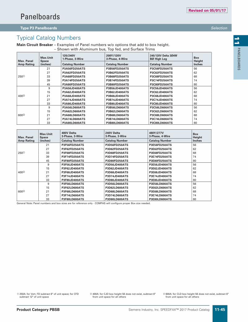
Siemens Industry, Inc. SPEEDFAX™ 2017 Product Catalog 11-45
11
PAN
ELBO
ARD
S
PanelboardsType P3 Panelboards Selection�
Product Category PBSB
250A: for Vert. FD subtract 6" of unit space; for CFD subtract 12" of unit space
400A: for CJD box height 56 does not exist, subtract 6" from unit space for all others
600A: for CLD box height 56 does not exist, subtract 6" from unit space for all others
Typical Catalog NumbersMain Circuit Breaker – Examples of Panel numbers w/o options that add to box height. – Shown with Aluminum bus, Top fed, and Surface Trims
Max. Panel Amp Rating
Max.Unit Space (inches)
120/240V1-Phase, 3-Wire
208Y/120V3-Phase, 4-Wire
240/120V Delta 3Ø4WBØ High Leg Box
Height InchesCatalog Number Catalog Number Catalog Number
250
21 P3A56FD250ATS P3B56FD250ATS P3C56FD250ATS 5627 P3A62FD250ATS P3B62FD250ATS P3C62FD250ATS 6233 P3A68FD250ATS P3B68FD250ATS P3C68FD250ATS 6839 P3A74FD250ATS P3B74FD250ATS P3C74FD250ATS 7445 P3A80FD250ATS P3B80FD250ATS P3C80FD250ATS 80
400
9 P3A56JD400ATS P3B56JD400ATS P3C56JD400ATS 5615 P3A62JD400ATS P3B62JD400ATS P3C62JD400ATS 6221 P3A68JD400ATS P3B68JD400ATS P3C68JD400ATS 6827 P3A74JD400ATS P3B74JD400ATS P3C74JD400ATS 7433 P3A80JD400ATS P3B80JD400ATS P3C80JD400ATS 80
600
9 P3A56LD600ATS P3B56LD600ATS P3C56LD600ATS 5615 P3A62LD600ATS P3B62LD600ATS P3C62LD600ATS 6221 P3A68LD600ATS P3B68LD600ATS P3C68LD600ATS 6827 P3A74LD600ATS P3B74LD600ATS P3C74LD600ATS 7433 P3A80LD600ATS P3B80LD600ATS P3C80LD600ATS 80
Max. Panel Amp Rating
Max.Unit Space (inches)
480V Delta3-Phase, 3-Wire
240V Delta3-Phase, 3-Wire
480Y/277V3-Phase, 4-Wire
Box Height InchesCatalog Number Catalog Number Catalog Number
250
21 P3F56FD250ATS P3D56FD250ATS P3E56FD250ATS 5627 P3F62FD250ATS P3D62FD250ATS P3E62FD250ATS 6233 P3F68FD250ATS P3D68FD250ATS P3E68FD250ATS 6839 P3F74FD250ATS P3D74FD250ATS P3E74FD250ATS 7445 P3F80FD250ATS P3D80FD250ATS P3E80FD250ATS 80
400
9 P3F56JD400ATS P3D56JD400ATS P3E56JD400ATS 5615 P3F62JD400ATS P3D62JD400ATS P3E62JD400ATS 6221 P3F68JD400ATS P3D68JD400ATS P3E68JD400ATS 6827 P3F74JD400ATS P3D74JD400ATS P3E74JD400ATS 7433 P3F80JD400ATS P3D80JD400ATS P3E80JD400ATS 80
600
9 P3F56LD600ATS P3D56LD600ATS P3E56LD600ATS 5615 P3F62LD600ATS P3D62LD600ATS P3E62LD600ATS 6221 P3F68LD600ATS P3D68LD600ATS P3E68LD600ATS 6827 P3F74LD600ATS P3D74LD600ATS P3E74LD600ATS 7433 P3F80LD600ATS P3D80LD600ATS P3E80LD600ATS 80
General Note: Panel numbers and box sizes are for reference only - COMPAS will configure proper Box size needed.
Revised on 05/01/17

Siemens Industry, Inc. SPEEDFAX™ 2017 Product Catalog11-46
11
PAN
ELB
OA
RDS
Accessories on 1" pole breakers (BL, BQD, ED) will take unit space.
Increase capacity neutral up to 200%
See page 11-47 for unit space adders and compatibility with other options.
Main Bus Amps
125250 400 600
Shunt Trip on Main or BranchBL, BLH, HBL, BQD, ED4, HED4, ED6, HHED6, QR2, QRH2, HQR2, HQR2H as branch only. BL, BLH, HBL, NGB, HGB, LGB, ED4, HED4, ED6, HHED6 uses 1" unit space for shunt trip. All others may be used on mains or subfeeds.
See page 11-102 and Breaker Section • Handle blocks
• Handle locks • Aux. Contacts
• UVR
TEY TEU1 Cat 60 LL803 LL806 Yale 47 (NYC) National C413A Best Lock 7-pin tumbler Southco 1/4" Fastener Corbin 1001 FAB7
Meters(Contact sales for pricing and application engineering for space requirements)
Panel Skirts See page 11-105
Special Locks (see page 11-7)
Branch and Main Breaker Accessories
Bus mounted SPD See Section 10 for TPS1
Main Bus Amps
125250400600
Copper MLO Only
(Devices mounted and wired to the trim should also have hinge-to-box trim specified)
Panel Bus Modifications
Main Bus
Catalog Number AdditionAmperes Ratings
125A 250A 400A 600A
750 A/SI AL. B B B BCopper (tin pltd.) F F F FCopper (silver pltd.)
E E E E
1000 A/SI Copper(tin pltd.)
G G G G
1000 A/SI Copper(silver pltd.)
H H H H
Time ClocksTime clocks may be mounted in a 23" enclosure to be cable connected to the panel. Sangamo, Tork or Paragon time clock can be supplied and mounted in panelboard cabinet. Adds 12" to panel height. Mounts in Sub-area.
Description
Time Clock (1 or 2-pole, single or double throw contacts; 3-pole, single throw) 277V maximum with plain dial Astronomical dial An omitting device Reserve power or carryover Space and mounting provisions only
Subfeed, Feed-Thru and Split Bus (for 2-pole or 3-pole)
AmpereRating
ConnectorCu/Al Wire Range
Unit Space
(inches)
Subfeed (Double) Lugs for Main Lug Panelboards Only (400 max)225/250 (2)—#6 AWG-350 kcmil 6
400 (4)—250 kcmil (2)—600 kcmil 6
Feed-Thru Lugs — Cannot Be Used in Conjunction with TVSS or Subfeed BreakersSee page 11-47 for unit space adders and compatibility with other options.225/250 (1)—#6 AWG-350 kcmil 6
400 (2)—250 kcmil(1)—600 kcmil 6
600 (2)—250-500 kcmil 9800 (2)—600 kcmil 12
Split Bus (1 per interior)225/250 (1)—#6 AWG-350 kcmil 6400 (2)—250 kcmil
(1)—600 kcmil6
600 (2)—250-500 kcmil 6800 (2)—600 kcmil 6
EnclosuresExtra Gutter to Sides or Ends of the Can (Type 1 Only) Description
6" end gutter2" side gutterBarrier in gutter (add to extra gutter price – min 4" required)
Hinged trimsPiano hinged trimsDoor-in-door trimsScrew to the box trims
Trim mounted devices . . . . .See page 11-104 • Pilot lights
• Toggle switches • Push buttons
Painted boxes . . . . . . . . . . . .See page 11-104Custom colors . . . . . . . . . . See painted boxesIncrease gauge trims and boxes . . . . . . . . . . . . . .See page 11-104Stainless steel trims, Type 1 . . . . . . . . . . . . . . . . .See page 11-104
PanelboardsType P3 Panelboard Modifications and Additions Selection�
Product Category PBSB
Type P3 Panelboards are factory labeled suitable for use as service entrance equipment when NEC requirements are met. A panelboard cannot have more than six main disconnects, unless it is a lighting and appliance branch panelboard. Lighting and appliance branch panelboards are limited to two main disconnects. Factory installed and Field installable Service Entrance Barrier kits are now available as required by UL67 (In COMPAS, you must select Service Entrance Required).
Service Entrance Label
Ground Bars except for brazed to box are shipped with the panel interior not factory mounted.
• Non-Insulated Equipment Ground Bar• Copper Non-Insulated Ground Bar• Al Insulated Equipment Ground Bar• Cu Insulated Equipment Ground Bar• Ground Bar Brazed to Box (Not recommended for painted or
NEMA 3R enclosures)
Grounding of Panelboards
Revised on 04/30/19

Siemens Industry, Inc. SPEEDFAX™ 2017 Product Catalog 11-47
11
PAN
ELBO
ARD
S
Subfeed Feed-thru FD JD FD 200% Min. Box Unit SpaceAmps Incoming Lugs Lugs Subfeed Subfeed Subfeeds Neutral Size (in.) (in.)
• — — — • 56 27 Main Lug Only — — • — — • 56 15 — — — • • 56 9 • — — — • 56 21 Main Lugs w/Subfeed Lugs • — • — — • 56 21 250 — — — • • 62 9
Main Breaker (Horiz. FD)
— • — — — • 56 21
— • — — • 56 9 Main Breaker (Vert. FD) None Std. • — — — • 56 15
Main Breaker (CFD)
None Std. • — — — • 56 9
— • — — • 68 9 • — — — — • 56 21 — • — — — • 56 15 Main Lug Only — — • — — • 56 9 — — — • — • 56 9 — — — — • • 62 9 — — — — • 56 9 • — — — • 62 9400 Main Breaker (JD) None Std. — • — — • 68 9 — — • — • 68 9 — — — • • 74 9 — — — — • 62 9 • — — — • 74 9 Main Breaker (CJD) None Std — • — — • 74 9 — — • — • 74 9 — — — • • 80 9 — — — — • 56 21 • — — — • 56 15 Main Lug Only — — • — — • 56 9 — — • — — 56 9 — — — • • 62 9 — — — — • 56 9 • — — — • 62 9600 Main Breaker LD — — • — — • 68 9 — — • — — 68 9 — — — • • 74 9 — — — — • 62 9 • — — — • 68 9 Main Breaker CLD — — • — — • 74 9 — — • — — 74 9 — — — • • 80 9 — — — — • 56 21 • — — — • 56 9800 Main Lug Only — — • — — • 56 9 — — • — — 56 9 — — — • • 62 9
Option Combinations
Subfed lugs are currently not offered as standard with main circuit breakers.
Subfed lugs on panels above 400A are not standard. 200% neutral cannot be provided along with a 400A
subfeed breaker because the breaker blocks the 4th lug site.
PanelboardsType P3 Panelboard Standard Modifications Selection�

Siemens Industry, Inc. SPEEDFAX™ 2017 Product Catalog11-48
11
PAN
ELB
OA
RDS
Enclosure Modifications
NEMA-4X For Type P3
Water Tight, Dust Tight and Corrosion Resistant(consult plant for actual enclosure size and for NEMA 4 enclosures)
Box Height Enclosure – Stainless SteelInches H W D 56 56 24 7.7562 62 24 7.7568 68 24 7.7574 74 24 7.7580 80 24 7.75
24" Panel Width Description
NEMA 3R enclosures NEMA 3R/12 enclosures Gasket between trim and box (Type 1)
Compression Lugs
StyleAmp Rating
Breaker Type
Compression Connectors
Box HeightAddition
MLO
250 N/A (1)#6 AWG - 350 kcmil —
400 N/A (1) 250 - 500 kcmil or(2)# 1/0 AWG - 250 kcmil
——
600 N/A (2)#3/0 AWG - 500 kcmil —800 N/A (2) 400-750 kcmil Cu only —
Main Breaker
250 FXD6, HFD6, CFD6 (1)#6 AWG - 350 kcmil Cu or Al CFD6 requires anadditional 6.0" box height
400 JD6, JXD6, HJD6, CJD6, SJD6, SHJD6, SCJD6 (2)#1/0 AWG - 500 kcmil Cu or Al —
600LD6, LXD6, HLD6, CJD6,SLD6, SHLD6, SCLD6
(2)#2/0 AWG - 500 kcmil Cu or Al —
Alternate Lugs
StyleAmp Rating
Breaker Type
Standard AL Connectors
Box HeightAddition
MLO400 N/A (1) 250 - 750 kcmil or
(2)#3/0 AWG - 250 kcmil Cu or Al 6
800 N/A (3)#4-500 Kcmil CU or Al capacity 6Main Breaker
400JD6, JXD6, HJD6, CJD6, SJD6, SHJD6, SCJD6
(1)#4/0 AWG - 750 kcmil Cu or Al 6
PanelboardsType P3 Panelboard Modifications and Additions Selection�
Product Category PBSB
16 Gauge Cans w/ 14 Gauge Front) 14 Gauge only 14 Gauge only - 304SS Std, 316SS Optional)
Revised on 04/30/19

Siemens Industry, Inc. SPEEDFAX™ 2017 Product Catalog 11-49
11
PAN
ELBO
ARD
S
Options For Type 1 TrimsItems must be ordered as manual line item on factoryHinged trim – Add “H” suffixDoor-in-door – Add “D” suffixMetal card holder – Add “M” suffix
Type P1, P2, and P3 PanelboardsMiscellaneous Parts and AccessoriesCatalog Number DescriptionEGK Al Ground Bus 44 ConnectionsBK1 Bonding kit for 250A max. and all P1 panelsIMK1 Interior Adjusting KitLPDC01 Directory Card (Pack of 10; ref. 12-1110-01)LPDC02 Directory Card Holder (Pack of 10; ref. 11-1824-01)NBK3 Number Strips 1-42. Snap-in type; Use w/P2 & P3 series PanelsNBK4 Number Strips 43-84. Snap-in type; Use w/P2 & P3 series PanelsNBK5 Number Strips 85-126. Snap-in type; Use w/P2 & P3 series PanelsNBK6 Number Strips 127-168. Snap-in type; Use w/P2 & P3 series PanelsNBK7 Number Strips 169-210. Snap-in type; Use w/P2 & P3 series PanelsNBK8 Number Strips 211-252. Snap-in type; Use w/P2 & P3 series PanelsECGK Cu Ground Bus 44 ConnectionsIGK Insulated Al Ground BusICGK Insulated Cu Ground BusEWK2 End Wall Kit with Knockouts (24" W x 7.75" DP)
DFFP1 1" Filler Plate (used for BL/BQD/xGB/xGB2/ED blank positions) (Suitable for replacing QF3 in P1 thru P5 Panelboards and Switchboards)
ANSI/NEMA PB 1.1-2013
General Instructions for Proper Installation, Operation, and Maintenance of Panelboards Rated 600 Volts or Less (O&M Manual)
��PDF can be downloaded (at no cost) and printed at this location: http://www.nema.org/standards/pages/Panelboards.aspx
Breaker Kits and AccessoriesKit Number Description Contents
BBKB32 (P2/P3) BL/BQD 6-pole 3" branch breaker kit Kit contains top barrier, (3) A/C connectors, (1) B connector, hardwareBBKNB32 (P2/P3) NGB, HGB, LGB 6-pole 3" branch breaker kit Kit contains top barrier, (3) A/C connectors, (1) B connector, hardwareBBKGB32 (P2/P3) NGB2, HGB2, LGB2 6-pole 3" branch breaker kit Kit contains top barrier, (3) A/C connectors, (1) B connector, hardwareBBKEB32 (P3) NEB/HEB 6-pole 3" branch breaker kit Kit contains top barrier, (3) A/C connectors, (1) B connector, hardware
BBKED32 (P2/P3) ED 6-pole 3" branch breaker kitKit contains breaker support, inter-phase barriers, (3) A/C connectors, (1) B connector, hardware
BBKQ2 (P3) Branch breaker kit for 2 and 3-pole QJ twin mountKit contains all connectors and cover plates necessary to mount both 2 and 3-pole breakers
BBKQR2 P3 twin BKR mounting kit for QR 1-phase/3-phase Kit contains all connectors and cover plates necessary to mount both 2 and 3-pole breakers (limit 6 QR per panel)
BBKVA52P3T P3 strap kit; twin mount 3VA52 branch Uses 6" of unit space. Includes 2x BBKVA52P3HW, barrier, straps, & mounting hardware.
BBKA52P3HW P3 branch breaker hardware kit Includes screw retainers & mounting screws.DFFP3 Deadfront filler 3" 3" empty space filler and hardwareDFFP6 Deadfront filler 6" 6" empty space filler and hardwareP3BK1 P3 bonding kit 800A max MLO+MB Bonding strap and hardware. For all MLO+MB configurations.EBF1 HEB/NEB Filler Plate Filler Plate
BBKQRP2FK P3 Filler for QR. Dual mount horizontal. 1-phase/3-phase.
Kit contains all cover plates necessary to change from QJ to QR both 2 and 3-pole breakers. For 1-phase panel, both breakers must change from QJ to QR, cannot have one of each installed.
SEBKP3V1 Service entrance barrier kit CFD, FD (P3 only) Kit contains barrier, mounting brackets, and hardwareSEBKP1P2P3V1 JD, LD Service Entrance Barrier Kit (RP1, P1, P2, P3) Kit contains barrier, mounting brackets, and hardware
SEBKP2V3 FD, QJ, QR Horizontal Main Service Entrance Barrier(P2, P2 with SEM3, P3) Kit contains barrier, mounting brackets, and hardware
��Although QR is rated 250A, it is limited to 225A in panelboard. Factory installed and Field installable Service Entrance Barrier kits are now available as required by UL67. (In COMPAS, you must select Service Entrance Required.) Maximum 6 large frame breakers in unit space. (QR + 3VA52)
Standard Enclosures
BoxHeight(in.)
Catalog Number
Type 1Standard Trim
Type 3R Type 3R/12Box Surface Flush
56 24WD56 P3S56 P3F56 24NRD56 24WPD5662 24WD62 P3S62 P3F62 24NRD62 24WPD6268 24WD68 P3S68 P3F68 24NRD68 24WPD6874 24WD74 P3S74 P3F74 24NRD74 24WPD7480 24WD80 P3S80 P3F80 24NRD80 24WPD80
PanelboardsType P3 Panelboard Kits and Accessories Selection�
Product Category PBSB
Revised on 04/30/19

Siemens Industry, Inc. SPEEDFAX™ 2017 Product Catalog11-50
11
PAN
ELB
OA
RDS
0.313 in. Dia.
(Mounting Holes0.437 in. Square)
(Mounting Holes0.437 in. Square)
10.0[254]
(Mounting Holes0.437 in. Square)
(Mounting Holes0.437 in. Square)
27.0 in.[ 686 ]
0.313 in. Dia.
(Mounting Holes0.437 in. Square)
(Mounting Holes0.437 in. Square)
10.0[254]
(Mounting Holes0.437 in. Square)
(Mounting Holes0.437 in. Square)
27.0 in.[ 686 ]
Type 1 BoxBox is symmetrical
Dimensions are interior of the box. Add 5/8" to width for absolute dimension. Add 1/8" to height for absolute dimension.
Dimensions shown in inches and millimeters [ ].
Type 3R and 3R/12 Box
PanelboardsType P3 Panelboards Dimensions�
(UL approved construction. 16 gage steel can with 14 gage front or similar approved construction.)
A60 Galvannealed with ANSI 61 light gray paint is standard.
(UL approved construction. 16 gage steel or equivalent alternate construction. 14 or 12 gage is available as an optional special order.)
G60 Galvanized is standard without paint.
Revised on 04/30/19

Siemens Industry, Inc. SPEEDFAX™ 2017 Product Catalog 11-51
11
PAN
ELBO
ARD
S
Panelboard Specific 3VA Accessories Available in Panelboards3VA Series Accessories There are 4 positions on each side of the trip handle of the 3VA52 breaker. Accessories can be 1, 2 or 3 positions wide and fit in specific locations as shown on charts and on the inside cover of each breaker.
Accessory types:
3VA breaker auxiliary releases allow remote electrical tripping of the circuit breaker
n STL – Shunt Trip Left
n STF – Shunt Trip Flexible
n UVR – Undervoltage Releases Trip
n UNI – Universal Release - Shunt Trip and an Undervoltage Release are Combined
Revised on 02/29/20
3VA accessories install easily.Special Hardware kit for P3 Twin Mount aligns screw for easy installation.
4/2 Siemens · 04/2017
4
3VA UL Molded Case Circuit BreakersAccessories and Spare Parts
Internal accessories
■ Overview
Color coding of accessories
A color coding system has been used to clearly identify the specific functions of individual accessories:
Auxiliary switches
All auxiliary and alarm switches for the 3VA UL molded case circuit breakers belong to an integrated range of accessories. The auxiliary switches can be simply snapped into place and connected up in the accessories compartment provided on the front face of the unit to the left and right of the handle.
The purpose of the auxiliary switches (AUX) is to signal the position of the main contacts of the molded case circuit breaker. The contacts of the auxiliary switches open and close simultaneously with the main contacts of the molded case circuit breaker.
Leading changeover switches (LCS) signal the opening of the main contacts with a lead time of 20 ms in advance of the circuit breaker opening and could be used to deactivate a frequency converter, for example.
Trip alarm switches (TAS) signal every circuit breaker tripping operation, regardless of the cause of the trip. The trip alarm switches are actuated whenever the molded case circuit breaker switches to the TRIP position.
Electrical alarm switches (EAS) are actuated as soon as the main contacts of the molded case circuit breaker open in the event that the breaker is tripped by the ETU.
Special electronically-compatible (el) variants are available for applications that require the auxiliary switch signals to be linked to low voltage systems.
Auxiliary releases
Auxiliary releases allow remote electrical tripping of the circuit breaker. They can be used to monitor control or main circuits in order to implement a protective system against accidental restart following a power failure, for example.
Undervoltage releases trip the 3VA UL molded case circuit breaker in the event that the rated voltage of a monitored circuit drops below a minimum permissible limit or fails altogether.
Shunt trips can be used to trip the 3VA UL molded case circuit breaker remotely. The STF variant can be mounted in either the left-hand or the right-hand accessories compartment (for 3VA6 only). The STL type is specifically designed for mounting in the left-hand compartment and is a very low power consumption device.
A universal release is a single, 21 mm wide component in which a shunt trip and an undervoltage release are combined. These are subject to the same tripping conditions as the individual devices.
24 V module Lock adapter for mounting thecylinder lock
STL
LCSEAS
COM060
STF
AUX
TAS
UVR UNI
I201_19551
Color Auxiliary switches and alarm switches Auxiliary releases
Black Auxiliary switch AUX • Shunt trip left STL• Shunt trip flexible STF
Gray Leading changeover switch LCS • Undervoltage release UVR
Yellow Trip alarm switch TAS --
Green Electrical alarm switch EAS --
Blue -- Universal release UNI
3VA6 ETU only
3VA52 Breaker Features3VA Internal Breaker Accessories configurations Accessory Slots
TMTU Thermal-Magnetic trip
Frame width
Amp range
3VA41 - 1-pole 1p 15-125 0
3VA41 - 1-pole in 2p frame2p 15-125
3
3VA41 - 2-pole 3
3VA41 - 3-pole 3p 15-125 6
3VA51 - 1-pole 1p 15-125 0
3VA51 - 1 pole in 2p frame 2p 15-125 3
3VA51 - 2 pole in 3p frame3p 15-125
6
3VA51 - 3-pole 6
3VA51 - 3-pole MCS 3p 100 6
3VA52 - 2-pole in 3p frame3p 100-250
8
3VA52 - 3-pole 8
3VA52 - 3-pole MCS 3p 100-250 8
3VA53 - 3-pole 3p 200-400 10
ETU - Electronic Trip*
3VA61 - 3 pole 3p 16-150 8
3VA62 - 3-pole 3p 40-250 8
3VA63 - 3-pole 3p 100-400 10
3VA64 - 3-pole 3p 160-600 10
* 100% rated may have reduced ranges
All Auxiliary and Alarm Switches for 3VA breakers belong to an integrated range of accessories
n AUX_HQ / AUX_HP – Auxiliary Switches
n LCS_HQ / LCS_HP – Leading Changeover Switches
n TAS_HQ / TAS_HP – Trip Alarm Switches
n EAS_HQ / EAS_HP – Electrical alarm switches
3VA Auxiliary and Alarm Switches have standard (HQ) and high capacity (HP) types as well as “electronic” versions for example: AUX_HQ_el
* Padlock accessory will be available in a future release.
3VA Breaker Configuration Information in Panelboards 3VA breaker Accessories Information Selection�

Siemens Industry, Inc. SPEEDFAX™ 2017 Product Catalog11-52
11
PAN
ELB
OA
RDS
P1 Lighting PanelboardP1 interiors have unit space setup for either:A) BL/BQD type of breakers only or B) xGB and 3VA41 breakers only in same interior
(no BL/BQD allowed)
Revised on 02/29/20
3VA Breaker Configuration Information in Panelboards P1 Lighting Panel General information Minimum�enclosure�size:�20"�wide�x�5.75"�deep�
Main Space
Subfeed Space
Deadfront Supports
Base Rails
Bus Bars:250A - CU or AL400A - CU or AL
Neutral Riser
Neutral Strips: 1/0 max. factory assembled (BL/BQD)
2/0 max. available for field install
2/0 max. std. for xGB/3VA41
A/C-Phase Connector- CU or AL
B-Phase Connector- CU or AL
P1 Lighting Panel
P1 Main Space can include:
Main Lugs: 250A or 400A maxMain Breaker Types:n 100A max BL/BQD & 125A max. xGB or EDn 125A max. 3VA41 (TMTU)
(horiz. mount)n 225A max. QR series (horizontal mount)n 250A max. FD series (horizontal mount)n 400A max. 3VA53/63 (TMTU/ETU)
(vertical mount)(ETU�=�Electronic�Trip�Unit)(TMTU�=�Thermal�Magnetic�Trip�Unit)n 400A max. JD series (vertical mount)
Future 3VA offering in development:n 250A max. 3VA52/62 (TMTU/ETU)
(horiz. mount)
P1 Branch Breakers — Small Frame only:
a) 100A max BL seriesb) 100A max BQD series c) 125A max xGB or 3VA41
series after 3/1/2020 (Cannot Mix with BL/BQD)Note: always check dead front labels
for allowed breakers
P1 Subfeed Space offering:
Feed-thru Lugs: A) 250A or 400AB) Surge Protection Devices (SPD)C) Subfeed Breakers: – 250A max. horizontal mounnt FD – 225A max. QR – 100A max. BL/BQD – 125A max. xGB/3VA41/ED
Future 3VA offering in development: – 250A max. 3VA52 TMTU – 250A max. 3VA62 ETU – Horizontal mount only

Siemens Industry, Inc. SPEEDFAX™ 2017 Product Catalog 11-53
11
PAN
ELBO
ARD
S
P2 Lighting PanelboardP2 interiors have flexible unit space setup for Multiple Branch Breaker Types and many different Main/Subfeed options.
Revised on 02/29/20
3VA Breaker Configuration Information in Panelboards P2 Lighting Panel General information Minimum�enclosure�size:�20"�wide�x�5.75"�deep�
Main Space
Subfeed Space
Deadfront Supports
Base Rails
Field installable Neutral Extension can be added for AFCI/GFCI when needed due to short pigtails. It can be positioned anywhere along the base rail on either side.kit # BNKP2EX1
BN
KP
2E
X1
Neutral Cross Strap– positions for
mounting Neutral lugs
– many different configurations are used.
Various Branch Breaker Strap Kits installed
P2 Lighting Panel
P2 Main Space can include:
Main Lugs: 125A, 250A, 400A or 600A==> also Subfeed Lugs: 125A, 250A or 400A
Main Breaker Types:n 100A max. BL/BQD or 125A max. xGB or EDn 250A max. FD series (horizontal mount) n 400A max. JD series (vertical mount) n 600A max. LD series (vertical mount)
Future 3VA offering in development:n 250A max. 3VA52/62 (TMTU/ETU)
(horiz. mount)n 400A max. 3VA53/63 (TMTU/ETU)
(vertical mount)n 600A max. 3VA54/64 (TMTU/ETU)
(vertical mount)(ETU�=�Electronic�Trip�Unit)(TMTU�=�Thermal�Magnetic�Trip�Unit)
P2 Branch Breakers — Small Frame:
a) 100A max BL seriesb) 100A max BQD series c) Various AFCI/GFCI seriesd) 125A max ED series (480V delta capable)e) 125A max xGB seriesf) 125A max GB2 series
(480V delta capable)
Future 3VA offering in development:g) 125A max. 3VA41 TMTU
(480V delta capable)
P2 Branch Breakers — Large Frame (6 max.)
1) 225A max QR series (total 225A/250A frame, four per panel limit)
Future 3VA offering in development:2) 150A max 3VA61 ETU single mount3) 250A max 3VA52/62 TMTU/ETU
single mount
Subfeed Space offering:
Feed-thru Lugs: A) 125A, 250A, 400A, or 600AB) Surge Protection Devices (SPD)C Subfeed Breakers: – 250A max. FD twin mount vertical – 400A max. JD single mount vertical
Future 3VA offering in development: – 400A max. 3VA53/63 (TMTU/ETU)
(vertical single mount)
Bus Bars:250A - CU or AL400A - CU or AL600A - CU or AL
Neutral Strips:1/0 max. cable size "Step lugs" and other varieties depending on the configuration– factory assembled
only– optional field installable
kits may be added in near future to include 2/0 capability.

Siemens Industry, Inc. SPEEDFAX™ 2017 Product Catalog11-54
11
PAN
ELB
OA
RDS
P3 Lighting PanelboardP3 interiors have flexible unit space setup for Multiple Branch Breaker Types and many different Main/Subfeed options.
Revised on 04/30/19
3VA Breaker Configuration Information in Panelboards P3 Lighting Panel General information Minimum�enclosure�size:�24"�wide�x�7.75"�deep�
Main Space
Subfeed Space
P3 interior is similar to P2 but has a 2 inch high riser to allow for larger Breakers and additional gutter space.
Bus Bars:250A - CU or AL400A - CU or AL600A - CU or AL800A - CU or AL
Neutral Strips:1/0 max. cable currently – factory assem-
bled only– optional field
installable kits may be added in near future to include 2/0 max. capacity neutral kits.
P3 Lighting Panel
P3 Main Space can include:
Main Lugs: 250A, 400A, 600A or 800A==> also Subfeed Lugs: 250A or 400A
Main Breaker Types:n 250A max. FD series (horizontal mount) n 400A max. JD series (vertical mount) n 600A max. LD series (vertical mount)
Future 3VA offering in development:n 250A max. 3VA52/62 (TMTU/ETU)
(horizontal mount)n 400A max. 3VA53/63 (TMTU/ETU)
(vertical mount)n 600A max. 3VA54/64 (TMTU/ETU)
(vertical mount)(ETU�=�Electronic�Trip�Unit)(TMTU�=�Thermal�Magnetic�Trip�Unit)
P3 Branch Breakers — Small Frame:
a) 100A max BL seriesb) 100A max BQD series c) Various AFCI/GFCI seriesd) 125A max ED series (480V delta capable)e) 125A max xGB seriesf) 125A max GB2 series (480V delta capable)
Future 3VA offering in development:g) 125A max. 3VA41 TMTU (480V delta
capable
P3 Branch Breakers — Large Frame (6 max.)
1) 225A max QR series (twin mount)2) 250A max 3VA52 Series (twin Mount)
(total 225A/250A frame, 6 per panel limit)
Future 3VA offering in development:3) 250A max 3VA62/3VA61 ETU single
mount
New 3VA offering has many field installable accessories available.
P3 Subfeed Space offering:
Feed-thru Lugs: A) 225A/250A, 400A, 600A or 800AB) Surge Protection Devices (SPD)C) Subfeed Breakers: – 250A max. FD twin mount vertical – 400A max. JD single mount vertical
Future 3VA offering in development: – 250A max. 3VA52/62 (TMTU/ETU)
(vertical twin mount) – 400A max. 3VA53/63 (TMTU/ETU)
(vertical single mount)
Neutral Cross Straps
Various Branch Breaker Strap Kits installed
Neutral Cross Straps– top and bottom – positions for
mounting up to four 350 kcmil Neutral lugs each
Main Lugs shown installed Base Rails
Deadfront Supports

Siemens Industry, Inc. SPEEDFAX™ 2017 Product Catalog 11-55
11
PAN
ELBO
ARD
S
P4 Power PanelP4 interiors have unit space setup for Multiple Branch Breaker Types and many different Main Breaker options.
Revised on 02/29/20
3VA Breaker Configuration Information in Panelboards P4 Power Panel General information Minimum�enclosure�size:�32"�wide�x�10"�deep�
Main Space– Mains are mounted
in unit space – All are horizontal mount
Unit Space below Bus
Vented Front Cover
Vented Front Cover P4 Standard Box Width is 32" W
Main Lugs shown installed
Neutral Connections*– at Main end
of panel– Various con-
figurations.* Depends on breaker selection - Consult fac-tory for details
SEM3 CT's installed
Various Branch Breaker Strap Kits installed
Bus Bars:CU or AL
P4 Unit Space below Bus: There is no actual Subfeed space.- All Space is unit space, but at the bottom below the bus, there can be additional components such as the SEM3 devices shown.
SEM3 Controller and Meter module racks
P4 Power Panel
P4 Main Space can include:
Main Lugs: 400A, 600A, 800A, 1000A or 1200A
Main Breaker Types: (horizontal mount)n 100A max. BL/BQD or 125A max. xGB or EDn 400A max. JD and VL-JG series n 600A max. LD and VL-LG series n 800A max. LM and VL-MG series
Future 3VA offering in development:n 400A max. 3VA53/63 (TMTU/ETU)n 600A max. 3VA54/64 (TMTU/ETU) n 800A max. 3VA55/65 (TMTU/ETU)
(ETU�=�Electronic�Trip�Unit)(TMTU�=�Thermal�Magnetic�Trip�Unit)
P4 Branch Breakers — Small Frame:
a) 100A max BL series (10, 22, 65 kaic @ 240V)
b) 100A max BQD series (14 kaic @ 480/277V)
c) Various AFCI/GFCI seriesd) 125A max ED series (480V delta capable)e) 125A max xGB seriesf) 125A max
GB2 series (480V delta capable)
Future 3VA offering in development:g) 125A max. 3VA41 TMTU
(480V delta capable)
P4 Branch Breakers — Large Frame (6 max.)
1) 150A max VL-DG series2) 150A 3VA61 ETU Series (new 2019)3) 225A max QR series4) 250A max FD or VL-FG series5) 250A max 3VA52/62 TMTU/ETU (new 2019)6) 400A max JD and VL-JG series7) 600A max. LD and VL-LG series8) 800A max. MD and VL-MG series
Future 3VA offering in development:9) 400A max. 3VA53/63 (TMTU/ETU)10) 600A max. 3VA54/64 (TMTU/ETU) 11) 800A max. 3VA55/65 (TMTU/ETU)
New 3VA offerings have many field installable accessories available including strap kits.
(See Strap Kit Table page 11-77).

Siemens Industry, Inc. SPEEDFAX™ 2017 Product Catalog11-56
11
PAN
ELB
OA
RDS
Revised on 02/29/20
3VA Breaker Configuration Information in Panelboards P5 Power Panel General information Minimum�enclosure�size:�38"�wide�x�10"�deep�
P5 Power PanelP5 interiors have unit space setup for Multiple Branch Breaker Types and many different Main Breaker options.
Unit Space below Bus
Vented Front Cover P5 Standard Box Width is 38" W
Neutral Connections*– at Main end
of panel– Various con-
figurations.* Depends on breaker selection - Consult fac-tory for details
SEM3 CT's installed
Various Branch Breaker Strap Kits installed
Bus Bars:CU or AL
P5 Unit Space below Bus: There is no actual Subfeed space.- All Space is unit space, but at the bottom below the bus, there can be additional components such as the SEM3 devices shown.
SEM3 Controller and Meter module racks
Main Lugs shown installed
Vented Front Cover
Main Space– Mains are mounted
in unit space – All are horizontal mount
P5 Power Panel
P4 Main Space can include:
Main Lugs: 400A, 600A, 800A, 1000A or 1200A
Main Breaker Types: (horizontal mount)n 400A max. JD and VL-JG series n 600A max. LD and VL-LG series n 800A max. LM and VL-MG series n 1200A max. ND and VL-NG series
Future 3VA offering in development:n 400A max. 3VA53/63 (TMTU/ETU)n 600A max. 3VA54/64 (TMTU/ETU)n 800A max. 3VA55/65 (TMTU/ETU)
(ETU�=�Electronic�Trip�Unit)(TMTU�=�Thermal�Magnetic�Trip�Unit)
P5 Branch Breakers — Small Frame:
a) 100A max BL seriesb) 100A max BQD series c) Various AFCI/GFCI seriesd) 125A max ED series
(480V delta capable)d) 125A max xGB seriese) 125A max GB2 series
(480V delta capable)
Future 3VA offering in development:f) 125A max. 3VA41 TMTU
(480V delta capable)
P5 Branch Breakers — Large Frame (6 max.)
1) 150A max VL-DG series2) 150A 3VA61 ETU Series (new 2019)3) 225A max QR series4) 250A max FD or VL-FG series5) 250A max 3VA52/62 TMTU/ETU
(new 2019)6) 400A max JD and VL-JG series7) 600A max. LD and VL-LG series8) 800A max. MD and VL-MG series9) 1200A max. ND and VL-NG series
Future 3VA offering in development:10) 400A max. 3VA53/63 (TMTU/ETU)11) 600A max. 3VA54/64 (TMTU/ETU) 12) 800A max. 3VA55/65 (TMTU/ETU)
(See Strap Kit Table page 11-91).

Siemens Industry, Inc. SPEEDFAX™ 2017 Product Catalog 11-57
11
PAN
ELBO
ARD
S
For Accessories and positions see tables on pages 11-64 and 11-68
Connector Kits for 3 Pole 3VA6 series Breakers
Description note: Use 3-pole for 2-pole applications
One Connector Kit required for each breaker when panel mounted.
Connector Kits AL CU
3VA61/62 3VA9243-0JB12 3VA9243-0JD123VA63 3VA9373-0JB13 3VA9373-0JD133VA64
3 Pole 3VA6 series Breakers without connectorsStandard in COMPAS includes ETU350 LSI Trip (Ir and Ii are adjustable)
ETU350 LSI included
ETU350 LSI included
ETU350 LSI included
ETU350 LSI included
kA ratings @ 50/60 Hz 3-pole 3-pole 3-pole 3-pole240 VAC kAIC rating ==> 100 100 200 200
480Y / 277 VAC kAIC rating ==> 35 65 100 150480 VAC kAIC rating ==> 35 65 100 150
600Y / 347 VAC kAIC rating ==> 18 22 35 50600 VAC kAIC rating ==> 18 22 35 50250 VDC kAIC rating ==> na na na na
amps Adj. Ir code
3VA61 UL Type Code / MB code ==> MDAE / W2 HDAE / W3 CDAE / W4 LDAE / W5
40 16-40 40 3VA61 3P breaker w/trip 3VA6140-5HN31-0AA0 3VA6140-6HN31-0AA0 3VA6140-7HN31-0AA0 3VA6140-8HN31-0AA0
100 40-100 10 3VA61 3P breaker w/trip 3VA6110-5HN31-0AA0 3VA6110-6HN31-0AA0 3VA6110-7HN31-0AA0 3VA6110-8HN31-0AA0
150 60-150 15 3VA61 3P breaker w/trip 3VA6115-5HN31-0AA0 3VA6115-6HN31-0AA0 3VA6115-7HN31-0AA0 3VA6115-8HN31-0AA03VA62 UL Type Code / MB code ==> MFAE / WA HFAE / WB CFAE / WC LFAE / WD
100 40-100 10 3VA62 3P breaker w/trip 3VA6210-5HN31-0AA0 3VA6210-6HN31-0AA0 3VA6210-7HN31-0AA0 3VA6210-8HN31-0AA0
250 100-250 25 3VA62 3P breaker w/trip 3VA6225-5HN31-0AA0 3VA6225-6HN31-0AA0 3VA6225-7HN31-0AA0 3VA6225-8HN31-0AA03VA63 UL Type Code / MB code ==> MJAE / WE HJAE / WF CJAE / WG LJAE / WH
250 100-250 25 3VA63 3P breaker w/trip 3VA6325-5HN31-0AA0 3VA6325-6HN31-0AA0 3VA6325-7HN31-0AA0 3VA6325-8HN31-0AA0
400 160-400 40 3VA63 3P breaker w/trip 3VA6340-5HN31-0AA0 3VA6340-6HN31-0AA0 3VA6340-7HN31-0AA0 3VA6340-8HN31-0AA03VA63 MCS UL Type Code / MB code ==> na na CJAE / WG na
400 na 40 3VA63 3P Molded Case Sw non adj. short circuit release Ii ==> 3VA6340-1BB31-0AA0 na
3VA64 UL Type Code / MB code ==> MLAE / WJ HLAE / WK CLAE / WL LLAE / WM
400 160-400 40 3VA64 3P breaker w/trip 3VA6440-5HN31-0AA0 3VA6440-6HN31-0AA0 3VA6440-7HN31-0AA0 3VA6440-8HN31-0AA0
600 240-600 60 3VA64 3P breaker w/trip 3VA6460-5HN31-0AA0 3VA6460-6HN31-0AA0 3VA6460-7HN31-0AA0 3VA6460-8HN31-0AA03VA64 MCS UL Type Code / MB code ==> na na CLAE / WL na
600 na 60 3VA64 3P Molded Case Sw non adj. short circuit release Ii ==> 3VA6460-1BB31-0AA0 na
3VA6 ETU – "Electronic Trip" versions of 3VA Breakers used in Panelboardsn See following pages for internal accessory pocket locations available in TMTU & ETU versions
n Standard part number shown for base trip unit - other variations available shown in lower chart
n Breakers shown do not include lugs - lugs are ordered separately as needed per application
n COMPAS will allow various Lug configurations based on Panel Type and mounting location
Electronic Trip Units available for 3VA61/62/63/64 series (COMPAS may require special Mod for some options)
Part # Differences Alternate Trips available Ir Ii Isd Ig Ground Fault type
Display and/or Metering Included
…HL31-0AA0 ETU320 LI Ir Ii — — na no…HM31-0AA0 ETU330 LIG Ir Ii — Ig Adjustable Protection (b) no…JP31-0AA0 ETU550 LSI with Display only Ir Ii Isd — na yes - Display only…JT31-0AA0 ETU556 LSI(G) with Display only Ir Ii Isd Ig Adjustable Alarm (a) yes - Display only…JQ31-0AA0 ETU560 LSI(G) with Display only Ir Ii Isd Ig Adjustable Protection (b) yes - Display only…KL31-0AA0 ETU820 LI w/Display & Metering Ir Ii — — na yes - both…KM31-0AA0 ETU830 LIG w/Display & Metering Ir Ii — Ig Adjustable Protection (b) yes - both…KP31-0AA0 ETU850 LSI w/Display & Metering Ir Ii Isd — na yes - both…KT31-0AA0 ETU856 LSI(G) w/Display & Metering Ir Ii Isd Ig Adjustable Alarm (a) yes - both…KQ31-0AA0 ETU860 LSIG w/Display & Metering Ir Ii Isd Ig Adjustable Protection (b) yes - both
Trip Unit Feature description and notes
Ir Adjustable Overload Protection
Ii Adjustable Instantaneous Short-Circuit Protection
Isd Adjustable Delayed Short-Circuit Protection
Ig Either (a) Adjustable Ground-Fault Alarm or (b) Adjustable Ground-Fault Protection (not both)
3VA Breaker Configuration Information in Panelboards 3VA Electronic Trip Units Selection�
Revised on 02/29/20
�The "L" series of UL type codes may not be available for use in all Panelboard types - check COMPAS for verification.

Siemens Industry, Inc. SPEEDFAX™ 2017 Product Catalog11-58
11
PAN
ELB
OA
RDS
Revised on 02/29/20
For Accessories and positions see tables on pages 11-64 and 11-68
Connector Kits for 3 Pole 3VA6 series Breakers – 100% rated (Requires CU Connectors)
Description note: Use 3-pole for 2-pole applications
One Connector Kit required for each breaker when panel mounted.
Connector Kits AL CU
3VA61/62 not allowed 3VA9243-0JD123VA63 not allowed 3VA9373-0JD133VA64
3 Pole 3VA6 series Breakers – 100% rated – without connectorsStandard in COMPAS includes ETU350 LSI Trip (Ir and Ii are adjustable)
ETU350 LSI included
ETU350 LSI included
ETU350 LSI included
ETU350 LSI included
kA ratings @ 50/60 Hz 3-pole 3-pole 3-pole 3-pole240 VAC kAIC rating ==> 100 100 200 200
480Y / 277 VAC kAIC rating ==> 35 65 100 150480 VAC kAIC rating ==> 35 65 100 150
600Y / 347 VAC kAIC rating ==> 18 22 35 50600 VAC kAIC rating ==> 18 22 35 50250 VDC kAIC rating ==> na na na na
amps Adj. Ir code
3VA61 UL Type Code / MB code ==> MDAE / W2 HDAE / W3 CDAE / W4 LDAE / W5
40 16-40 40 3VA61 3P breaker w/trip 3VA6140-5HN31-2AA0 3VA6140-6HN31-2AA0 3VA6140-7HN31-2AA0 3VA6140-8HN31-2AA0
100 40-100 10 3VA61 3P breaker w/trip 3VA6110-5HN31-2AA0 3VA6110-6HN31-2AA0 3VA6110-7HN31-2AA0 3VA6110-8HN31-2AA0
150 60-150 15 3VA61 3P breaker w/trip 3VA6115-5HN31-2AA0 3VA6115-6HN31-2AA0 3VA6115-7HN31-2AA0 3VA6115-8HN31-2AA03VA62 UL Type Code / MB code ==> MFAE / WA HFAE / WB CFAE / WC LFAE / WD
100 40-100 10 3VA62 3P breaker w/trip 3VA6210-5HN31-2AA0 3VA6210-6HN31-2AA0 3VA6210-7HN31-2AA0 3VA6210-8HN31-2AA0
250 100-250 25 3VA62 3P breaker w/trip 3VA6225-5HN31-2AA0 3VA6225-6HN31-2AA0 3VA6225-7HN31-2AA0 3VA6225-8HN31-2AA03VA63 UL Type Code / MB code ==> MJAE / WE HJAE / WF CJAE / WG LJAE / WH
250 100-250 25 3VA63 3P breaker w/trip 3VA6325-5HN31-2AA0 3VA6325-6HN31-2AA0 3VA6325-7HN31-2AA0 3VA6325-8HN31-2AA03VA64 UL Type Code / MB code ==> MLAE / WJ HLAE / WK CLAE / WL LLAE / WM
400 160-400 40 3VA64 3P breaker w/trip 3VA6440-5HN31-2AA0 3VA6440-6HN31-2AA0 3VA6440-7HN31-2AA0 3VA6440-8HN31-2AA0
3VA6 100% rated ETU – "Electronic Trip" versions of 3VA Breakers in Panelboardsn See following pages for internal accessory pocket locations available in TMTU & ETU versions
n Breakers shown do not include lugs - lugs are ordered separately as needed per application
n COMPAS will allow various Lug configurations based on Panel Type and mounting location
Electronic Trip Units available for 3VA61/62/63/64 series (COMPAS may require special Mods for some options)
Part # Differences Alternate Trips available Ir Ii Isd Ig Ground Fault type
Display and/or Metering Included
…HL31-0AA0 ETU320 LI Ir Ii — — na no…HM31-0AA0 ETU330 LIG Ir Ii — Ig Adjustable Protection (b) no…JP31-0AA0 ETU550 LSI with Display only Ir Ii Isd — na yes - Display only…JT31-0AA0 ETU556 LSI(G) with Display only Ir Ii Isd Ig Adjustable Alarm (a) yes - Display only…JQ31-0AA0 ETU560 LSI(G) with Display only Ir Ii Isd Ig Adjustable Protection (b) yes - Display only…KL31-0AA0 ETU820 LI w/Display & Metering Ir Ii — — na yes - both…KM31-0AA0 ETU830 LIG w/Display & Metering Ir Ii — Ig Adjustable Protection (b) yes - both…KP31-0AA0 ETU850 LSI w/Display & Metering Ir Ii Isd — na yes - both…KT31-0AA0 ETU856 LSI(G) w/Display & Metering Ir Ii Isd Ig Adjustable Alarm (a) yes - both…KQ31-0AA0 ETU860 LSIG w/Display & Metering Ir Ii Isd Ig Adjustable Protection (b) yes - both
Trip Unit Feature description and notes
Ir Adjustable Overload Protection
Ii Adjustable Instantaneous Short-Circuit Protection
Isd Adjustable Delayed Short-Circuit Protection
Ig Either (a) Adjustable Ground-Fault Alarm or (b) Adjustable Ground-Fault Protection (not both)
3VA Breaker Configuration Information in Panelboards 3VA Electronic Trip Units — 100% Rated Selection�
�The "L" series of UL type codes may not be available for use in all Panelboard types - check COMPAS for verification.

Siemens Industry, Inc. SPEEDFAX™ 2017 Product Catalog 11-59
11
PAN
ELBO
ARD
S
3VA6 Communications modules and related accessories for field installation
n COMPAS may not allow some of these kits for selection - Special Mod may be required.
n Some items may not be installed in panels and may be shipped separate from Panels even if Configured in COMPAS
3VA Breaker Configuration Information in Panelboards Communications Modules Selection�
Description
Quick reference code
Voltage AC max or range
Voltage DC max or range
Accessory Catalog Number
Qty of slots in breaker req'd
Max. Qty. per Brkr
Position to install for3VA61/62 and3VA63/64 only
GroupLeft side pocket Right side pocket
Pocket reference # ==> 25 24 23 22 21 11 12 13 14 15
COM Modules and CablesCommunications Module - 3VA61/62 COM060 n/a 24VDC 3VA9177-0TB10 4 1 XCommunications Module - 3VA63/64 COM060 n/a 24VDC 3VA9377-0TB10 4 1 XCOM060-to-T-Connector ext. cable 0.4 m COM060-to-T n/a n/a 3VA9987-0TF20 n/a n/a ExternalCOM060-to-T-Connector ext. cable 0.8 m COM060-to-T n/a n/a 3VA9987-0TF10 n/a n/a ExternalCOM060 T-Connector (spare part) T-Connector n/a n/a 3VA9987-0TG10 n/a n/a ExternalTerminal Resistor TermRes n/a n/a 3VA9987-0TE10 n/a n/a ExternalCOM800 Breaker Data Server = max 8 COM800 n/a n/a 3VA9977-0TA10 n/a n/a P4/P5 only and SWBDCOM100 Breaker Data Server = max 1 COM100 n/a n/a 3VA9977-0TA20 n/a n/a P4/P5 only and SWBDCOM100-800 extension cable 0.4 m COM ext Cable n/a n/a 3VA9987-0TC10 n/a n/a P4/P5 only and SWBDCOM100-800 extension cable 1 m COM ext Cable n/a n/a 3VA9987-0TC20 n/a n/a P4/P5 only and SWBDCOM100-800 extension cable 2 m COM ext Cable n/a n/a 3VA9987-0TC30 n/a n/a P4/P5 only and SWBDCOM100-800 extension cable 4 m COM ext Cable n/a n/a 3VA9987-0TC40 n/a n/a P4/P5 only and SWBD7KM Pac Profibus DP Expansion Module 7KMAB n/a n/a 7KM9300-0AB01-0AA0 n/a n/a P4/P5 only and SWBD7KM PAC Switched Ethernet Profinet Expansion Module 7KMAE n/a n/a 7KM9300-0AE01-0AA0 n/a n/a P4/P5 only and SWBD
7KM PAC RS485 Modbus RTU Exp. Module 7KMAM n/a n/a 7KM9300-0AM00-0AA0 n/a n/a P4/P5 only and SWBD
DAS, Displays and Related ComponentsDAS Module "Maintenance Mode Box" MMB300 n/a n/a 3VA9977-0UF10 n/a n/a P4/P5 only and SWBDEFB300 - External function box EFB300 n/a n/a 3VA9977-0UA10 n/a n/a P4/P5 only and SWBDDisplay - DSP800 DSP800 n/a n/a 3VA9977-0TD10 n/a n/a P4/P5 only and SWBD1.5m Connecting cable for MMB300/EFB300 MMB/EFB 1.5m n/a n/a 3VA9987-UB10 n/a n/a P4/P5 only and SWBD3.0m Connecting cable for MMB300/EFB300 MMB/EFB 3.0m n/a n/a 3VA9987-UB20 n/a n/a P4/P5 only and SWBD
Motor OperatorsM0320 Motor Operator - 24-60V DC M0320 n/a 24-60V 3VA9447-0HA10 n/a 1 P4/P5 only and SWBD
M0320 Motor Operator - 110-230V AC or 110-250V DC EFB300 n/a n/a 3VA9977-0UA10 n/a 1 P4/P5 only and SWBD
Misc. External Components and CablesNeutral Current Transformer, In = 25-150A NCT150 n/a n/a 3VA9077-0NA10 n/a n/a P4/P5 only and SWBDNeutral Current Transformer, In= 160-350A NCT350 n/a n/a 3VA9177-0NA10 n/a n/a P4/P5 only and SWBDNeutral Current Transformer, In = 400-630A NCT630 n/a n/a 3VA9377-0NA10 n/a n/a P4/P5 only and SWBDTD300 - Activation & Trip Box TD300 n/a n/a 3VA9977-0MA10 n/a n/a P4/P5 only and SWBDTD500 - Test device TD500 n/a n/a 3VA9977-0MB10 n/a n/a P4/P5 only and SWBDTD500 External Power Supply TD500EX n/a n/a 3VA9987-0MX10 n/a n/a P4/P5 only and SWBDCable to connect to TD500 from 3VA6 TD500CBL n/a n/a 3VA9977-0MY10 n/a n/a P4/P5 only and SWBD
Special Connector Lugs with Control Wire Tap#14-3/0 AL wire connector Kit w/con-tap AL-lug 3VA51 3VA9133-0JG11 125A TMTU only Line or Load end as needed #14-2/0 CU wire connector Kit w/con-tap CU-lug 3VA51 3VA9133-0JK11 125A TMTU only Line or Load end as needed #6-350 kcmil AL wire conn. Kit w/con-tap AL-lug 3VA52 3VA9233-0JG12 250A TMTU only Line or Load end as needed #6-350 kcmil CU wire conn. Kit w/con-tap CU-lug 3VA52 3VA9233-0JK12 250A TMTU only Line or Load end as needed
#14-1/0 AL wire connector Kit w/con-tap AL-lug 3VA61 3VA9143-0JG11 150A ETU only Line or Load end as needed #6-350 kcmil AL wire conn. Kit w/con-tap AL-lug 3VA61/62 3VA9243-0JG12 150/250A ETU only Line or Load end as needed #14-1/0 CU wire connector Kit w/con-tap CU-lug 3VA61 3VA9143-0JK11 150A ETU only Line or Load end as needed #6-350 kcmil CU wire conn. Kit w/con-tap CU-lug 3VA61/62 3VA9243-0JK12 150/250A ETU only Line or Load end as needed
#1-600 kcmil AL wire conn. Kit w/con-tap AL-lug 3VA53/63 3VA9373-0JG13 400A TMTU or ETU Line or Load end as needed #1-600 kcmil CU wire conn. Kit w/con-tap CU-lug 3VA53/63 3VA9373-0JK13 400A TMTU or ETU Line or Load end as needed 2/0-600 kcmil AL 2 port conn. Kit w/con-tap AL-2lug 3VA54/64 3VA9473-0JC23 600A TMTU or ETU Line or Load end as needed
Some accessories may be "field install only" if not available in COMPAS, or not available for use in Panelboards
Many accessories available for the 3VA5 and 3VA6 breakers may not be suitable for use in Lighting Panelboards.
- COMPAS allows only options that are available for factory assembly.
Some accessories listed above may not be available for all Panelboard configurations. Lugs are NOT supplied with loose breaker as standard - must order seperately or
configure in COMPAS to include lugs. - Factory assembled panels include AL lugs as standard without control wire tap,
CU lugs are optional. These kits include 3 connectors and hardware.
Revised on 04/30/19

Siemens Industry, Inc. SPEEDFAX™ 2017 Product Catalog11-60
11
PAN
ELB
OA
RDS
3VA411-Pole Description
1 Pole 3VA41with AL connectors included – for 14 AWG to 3/0 - CU/AL cablefor CU order one 3VA9133-0JD11 connector kitNote: No accessory pockets available – see 1-pole in 2-pole frame
UL Type Code ==> SEAB MEAB HEAB
Panelboard MB codes ==> V1 V2 V3
120 VAC kAIC rating ==> 65 85 150
277 VAC kAIC rating ==> 25 35 65347 VAC kAIC rating ==> 14 18 25
125 VDC kAIC rating ==> 14 25 30IC family @ 277 VAC ==> 25kA 35kA 65kA
FTFM Trip included ==> TM210 TM210 TM210
Amps Code Description
Catalog Number Catalog Number Catalog Number
1-pole 1-pole 1-pole
15 95 3VA41 1P breaker w/TM210 3VA4195-4ED14-0AA0 3VA4195-5ED14-0AA0 3VA4195-6ED14-0AA0 20 20 3VA41 1P breaker w/TM210 3VA4120-4ED14-0AA0 3VA4120-5ED14-0AA0 3VA4120-6ED14-0AA0 25 25 3VA41 1P breaker w/TM210 3VA4125-4ED14-0AA0 3VA4125-5ED14-0AA0 3VA4125-6ED14-0AA0 30 30 3VA41 1P breaker w/TM210 3VA4130-4ED14-0AA0 3VA4130-5ED14-0AA0 3VA4130-6ED14-0AA0 35 35 3VA41 1P breaker w/TM210 3VA4135-4ED14-0AA0 3VA4135-5ED14-0AA0 3VA4135-6ED14-0AA0 40 40 3VA41 1P breaker w/TM210 3VA4140-4ED14-0AA0 3VA4140-5ED14-0AA0 3VA4140-6ED14-0AA0 45 45 3VA41 1P breaker w/TM210 3VA4145-4ED14-0AA0 3VA4145-5ED14-0AA0 3VA4145-6ED14-0AA0 50 50 3VA41 1P breaker w/TM210 3VA4150-4ED14-0AA0 3VA4150-5ED14-0AA0 3VA4150-6ED14-0AA0 60 60 3VA41 1P breaker w/TM210 3VA4160-4ED14-0AA0 3VA4160-5ED14-0AA0 3VA4160-6ED14-0AA0 70 70 3VA41 1P breaker w/TM210 3VA4170-4ED14-0AA0 3VA4170-5ED14-0AA0 3VA4170-6ED14-0AA0 80 80 3VA41 1P breaker w/TM210 3VA4180-4ED14-0AA0 3VA4180-5ED14-0AA0 3VA4180-6ED14-0AA0 90 90 3VA41 1P breaker w/TM210 3VA4190-4ED14-0AA0 3VA4190-5ED14-0AA0 3VA4190-6ED14-0AA0
100 10 3VA41 1P breaker w/TM210 3VA4110-4ED14-0AA0 3VA4110-5ED14-0AA0 3VA4110-6ED14-0AA0 110 11 3VA41 1P breaker w/TM210 3VA4111-4ED14-0AA0 3VA4111-5ED14-0AA0 3VA4111-6ED14-0AA0 125 12 3VA41 1P breaker w/TM210 3VA4112-4ED14-0AA0 3VA4112-5ED14-0AA0 3VA4112-6ED14-0AA0
3VA411-Pole in 2-Pole Description
1 Pole in 2-Pole Frame 3VA41with AL connectors included for CU order one 3VA9133-0JD11 connector kitNote: Only 3 Left side Accessory pockets available
amps code Description
Catalog Number Catalog Number Catalog Number
1-Pole in 2-Pole Frame 1-Pole in 2-Pole Frame 1-Pole in 2-Pole Frame
15 95 3VA41 1P breaker w/TM210 3VA4195-4ED54-0AA0 3VA4195-5ED54-0AA0 3VA4195-6ED54-0AA0 20 20 3VA41 1P breaker w/TM210 3VA4120-4ED54-0AA0 3VA4120-5ED54-0AA0 3VA4120-6ED54-0AA0 25 25 3VA41 1P breaker w/TM210 3VA4125-4ED54-0AA0 3VA4125-5ED54-0AA0 3VA4125-6ED54-0AA0 30 30 3VA41 1P breaker w/TM210 3VA4130-4ED54-0AA0 3VA4130-5ED54-0AA0 3VA4130-6ED54-0AA0 35 35 3VA41 1P breaker w/TM210 3VA4135-4ED54-0AA0 3VA4135-5ED54-0AA0 3VA4135-6ED54-0AA0 40 40 3VA41 1P breaker w/TM210 3VA4140-4ED54-0AA0 3VA4140-5ED54-0AA0 3VA4140-6ED54-0AA0 45 45 3VA41 1P breaker w/TM210 3VA4145-4ED54-0AA0 3VA4145-5ED54-0AA0 3VA4145-6ED54-0AA0 50 50 3VA41 1P breaker w/TM210 3VA4150-4ED54-0AA0 3VA4150-5ED54-0AA0 3VA4150-6ED54-0AA0 60 60 3VA41 1P breaker w/TM210 3VA4160-4ED54-0AA0 3VA4160-5ED54-0AA0 3VA4160-6ED54-0AA0 70 70 3VA41 1P breaker w/TM210 3VA4170-4ED54-0AA0 3VA4170-5ED54-0AA0 3VA4170-6ED54-0AA0 80 80 3VA41 1P breaker w/TM210 3VA4180-4ED54-0AA0 3VA4180-5ED54-0AA0 3VA4180-6ED54-0AA0 90 90 3VA41 1P breaker w/TM210 3VA4190-4ED54-0AA0 3VA4190-5ED54-0AA0 3VA4190-6ED54-0AA0
100 10 3VA41 1P breaker w/TM210 3VA4110-4ED54-0AA0 3VA4110-5ED54-0AA0 3VA4110-6ED54-0AA0 110 11 3VA41 1P breaker w/TM210 3VA4111-4ED54-0AA0 3VA4111-5ED54-0AA0 3VA4111-6ED54-0AA0 125 12 3VA41 1P breaker w/TM210 3VA4112-4ED54-0AA0 3VA4112-5ED54-0AA0 3VA4112-6ED54-0AA0
3VA41 1 Pole Breakers
3VA41 TMTU 125A max. - breakers include AL lugs installed
3VA Breaker Configuration Information in Panelboards 3VA41 Breakers – 1 Pole and 1 Pole in 2-Pole Frame Selection�
TMTU frame Type
kA code
Type ref
MB code
3VA41 SEAB S EAB V13VA41 MEAB M EAB V23VA41 HEAB H EAB V3
Revised on 02/29/20
Although some breakers have a kAIC rating above 100 kAIC – many panels are limited to 100 kAIC or less.
DC Voltage panels are limited by various factors. These DC ratings apply to the Breaker only.

Siemens Industry, Inc. SPEEDFAX™ 2017 Product Catalog 11-61
11
PAN
ELBO
ARD
S
3VA413-Pole Description
3 Pole 3VA41with AL connectors included – for 14 AWG to 3/0 - CU/AL cablefor CU order one 3VA9133-0JD11 connector kit
UL Type Code ==> SEAB MEAB HEAB
Panelboard MB codes ==> V1 V2 V3
Ratings 3-pole | 2-pole 3-pole | 2-pole 3-pole | 2-pole240 VAC kAIC rating ==> 65 | 65 85 | 85 150 | 150
480Y / 277 VAC kAIC rating ==> 25 | 25 35 | 35 65 | 65480 VAC kAIC rating ==> 25 | 25 35 | 35 65 | 65
600Y / 347 VAC kAIC rating ==> 14 | 14 18 | 18 25 | 25600 VAC kAIC rating ==> na | na na | na na | na
250 VDC kAIC rating ==> na | 50 na | 85 na | 100IC family @ 277 VAC ==> 25kA 35kA 65kA
FTFM Trip included ==> TM210 TM210 TM210
Amps Code Description
Catalog Number Catalog Number Catalog Number
3-pole 3-pole 3-pole
15 95 3VA41 3P breaker w/TM230 3VA4195-4ED34-0AA0 3VA4195-5ED34-0AA0 3VA4195-6ED34-0AA0 20 20 3VA41 3P breaker w/TM230 3VA4120-4ED34-0AA0 3VA4120-5ED34-0AA0 3VA4120-6ED34-0AA0 25 25 3VA41 3P breaker w/TM230 3VA4125-4ED34-0AA0 3VA4125-5ED34-0AA0 3VA4125-6ED34-0AA0 30 30 3VA41 3P breaker w/TM230 3VA4130-4ED34-0AA0 3VA4130-5ED34-0AA0 3VA4130-6ED34-0AA0 35 35 3VA41 3P breaker w/TM230 3VA4135-4ED34-0AA0 3VA4135-5ED34-0AA0 3VA4135-6ED34-0AA0 40 40 3VA41 3P breaker w/TM230 3VA4140-4ED34-0AA0 3VA4140-5ED34-0AA0 3VA4140-6ED34-0AA0 45 45 3VA41 3P breaker w/TM230 3VA4145-4ED34-0AA0 3VA4145-5ED34-0AA0 3VA4145-6ED34-0AA0 50 50 3VA41 3P breaker w/TM230 3VA4150-4ED34-0AA0 3VA4150-5ED34-0AA0 3VA4150-6ED34-0AA0 60 60 3VA41 3P breaker w/TM230 3VA4160-4ED34-0AA0 3VA4160-5ED34-0AA0 3VA4160-6ED34-0AA0 70 70 3VA41 3P breaker w/TM230 3VA4170-4ED34-0AA0 3VA4170-5ED34-0AA0 3VA4170-6ED34-0AA0 80 80 3VA41 3P breaker w/TM230 3VA4180-4ED34-0AA0 3VA4180-5ED34-0AA0 3VA4180-6ED34-0AA0 90 90 3VA41 3P breaker w/TM230 3VA4190-4ED34-0AA0 3VA4190-5ED34-0AA0 3VA4190-6ED34-0AA0
100 10 3VA41 3P breaker w/TM230 3VA4110-4ED34-0AA0 3VA4110-5ED34-0AA0 3VA4110-6ED34-0AA0 110 11 3VA41 3P breaker w/TM230 3VA4111-4ED34-0AA0 3VA4111-5ED34-0AA0 3VA4111-6ED34-0AA0 125 12 3VA41 3P breaker w/TM230 3VA4112-4ED34-0AA0 3VA4112-5ED34-0AA0 3VA4112-6ED34-0AA0
Molded Case Switch
100 10 3VA41 3P MCS 65 kA na na 3VA4110-1BB31-0AA0
3VA412-Pole Description
2 Pole 3VA41with AL connectors included for CU order one 3VA9133-0JD11 connector kitNote: Only 3 Left side Accessory pockets available
Amps Code Description
Catalog Number Catalog Number Catalog Number
2-pole 2-pole 2-pole
15 95 3VA41 2P breaker w/TM230 3VA4195-4ED24-0AA0 3VA4195-5ED24-0AA0 3VA4195-6ED24-0AA0 20 20 3VA41 2P breaker w/TM230 3VA4120-4ED24-0AA0 3VA4120-5ED24-0AA0 3VA4120-6ED24-0AA0 25 25 3VA41 2P breaker w/TM230 3VA4125-4ED24-0AA0 3VA4125-5ED24-0AA0 3VA4125-6ED24-0AA0 30 30 3VA41 2P breaker w/TM230 3VA4130-4ED24-0AA0 3VA4130-5ED24-0AA0 3VA4130-6ED24-0AA0 35 35 3VA41 2P breaker w/TM230 3VA4135-4ED24-0AA0 3VA4135-5ED24-0AA0 3VA4135-6ED24-0AA0 40 40 3VA41 2P breaker w/TM230 3VA4140-4ED24-0AA0 3VA4140-5ED24-0AA0 3VA4140-6ED24-0AA0 45 45 3VA41 2P breaker w/TM230 3VA4145-4ED24-0AA0 3VA4145-5ED24-0AA0 3VA4145-6ED24-0AA0 50 50 3VA41 2P breaker w/TM230 3VA4150-4ED24-0AA0 3VA4150-5ED24-0AA0 3VA4150-6ED24-0AA0 60 60 3VA41 2P breaker w/TM230 3VA4160-4ED24-0AA0 3VA4160-5ED24-0AA0 3VA4160-6ED24-0AA0 70 70 3VA41 2P breaker w/TM230 3VA4170-4ED24-0AA0 3VA4170-5ED24-0AA0 3VA4170-6ED24-0AA0 80 80 3VA41 2P breaker w/TM230 3VA4180-4ED24-0AA0 3VA4180-5ED24-0AA0 3VA4180-6ED24-0AA0 90 90 3VA41 2P breaker w/TM230 3VA4190-4ED24-0AA0 3VA4190-5ED24-0AA0 3VA4190-6ED24-0AA0
100 10 3VA41 2P breaker w/TM230 3VA4110-4ED24-0AA0 3VA4110-5ED24-0AA0 3VA4110-6ED24-0AA0 110 11 3VA41 2P breaker w/TM230 3VA4111-4ED24-0AA0 3VA4111-5ED24-0AA0 3VA4111-6ED24-0AA0 125 12 3VA41 2P breaker w/TM230 3VA4112-4ED24-0AA0 3VA4112-5ED24-0AA0 3VA4112-6ED24-0AA0
3VA41 2 and 3 Pole Breakers
3VA41 TMTU 125A max. - breakers include AL lugs installed
3VA Breaker Configuration Information in Panelboards 3VA41 Breakers – 2 Pole and 3 Pole Selection�
TMTU frame Type
kA code
Type ref
MB code
3VA41 SEAB S EAB V13VA41 MEAB M EAB V23VA41 HEAB H EAB V3
Revised on 02/29/20
Although some breakers have a kAIC rating above 100 kAIC – many panels are limited to 100 kAIC or less.
DC Voltage panels are limited by various factors. These DC ratings apply to the Breaker only.

Siemens Industry, Inc. SPEEDFAX™ 2017 Product Catalog11-62
11
PAN
ELB
OA
RDS
Description
Quick reference code
Voltage AC max or range
Voltage DC max or range
Accessory Catalog Number
Qty of slots in breaker req'd
Max. Qty. per Brkr
Position to install for 3VA41/51 only
AccessoriesLeft side Right side
Pocket reference # ==> 23 22 21 11 12 13
Inte
rnal
Acc
esso
ries
Left
sid
e o
nly
On
ly o
ne
per
bre
aker
allo
wed
Shunt trip left -10 STL-10 n/a 12 3VA9978-0BL10 3 1 XShunt trip left -20 STL-20 380...600 n/a 3VA9978-0BL20 3 1 XShunt trip left -30 STL-30 24 24…30 3VA9978-0BL30 3 1 XShunt trip left -31 STL-31 48…60 n/a 3VA9978-0BL31 3 1 XShunt trip left -32 STL-32 110…127 110…127 3VA9978-0BL32 3 1 XShunt trip left -33 STL-33 208…277 220…250 3VA9978-0BL33 3 1 X
Shunt trip flexible -20 STF-20 24 n/a 3VA9978-0BA20 3 1 XShunt trip flexible -21 STF-21 48…60 n/a 3VA9978-0BA21 3 1 XShunt trip flexible -22 STF-22 110…127 n/a 3VA9978-0BA22 3 1 XShunt trip flexible -23 STF-23 208…277 n/a 3VA9978-0BA23 3 1 XShunt trip flexible -24 STF-24 380…500 n/a 3VA9978-0BA24 3 1 XShunt trip flexible -25 STF-25 600 n/a 3VA9978-0BA25 3 1 X
Undervoltage release -10 UVR-10 n/a 12 3VA9978-0BB10 3 1 XUndervoltage release -11 UVR-11 n/a 24 3VA9978-0BB11 3 1 XUndervoltage release -12 UVR-12 n/a 48 3VA9978-0BB12 3 1 XUndervoltage release -14 UVR-14 n/a 125…127 3VA9978-0BB14 3 1 XUndervoltage release -16 UVR-16 n/a 250 3VA9978-0BB16 3 1 XUndervoltage release -20 UVR-20 24 n/a 3VA9978-0BB20 3 1 XUndervoltage release -24 UVR-24 120…127 n/a 3VA9978-0BB24 3 1 XUndervoltage release -25 UVR-25 208…230 n/a 3VA9978-0BB25 3 1 XUndervoltage release -27 UVR-27 440…480 n/a 3VA9978-0BB27 3 1 X
Universal release UNI-11 n/a 12vdc 3VA9978-0BD11 3 1 XUniversal release UNI-12 n/a 24vdc 3VA9978-0BD12 3 1 XUniversal release UNI-13 n/a 48vdc 3VA9978-0BD13 3 1 X
Inte
rnal
Acc
esso
ries
Rig
ht
sid
e o
r le
ft
sid
e o
pti
on
s
Auxiliary switch - standard AUX_HQ 240VAC n/a 3VA9978-0AA12 1 6 X X X X X XLeading Chg-over SW - standard LCS_HQ 240VAC n/a 3VA9978-0AA22 1 1 XTrip alarm (bell alarm) - standard TAS_HQ 240VAC 250VDC 3VA9978-0AB12 1 4 X X X X
Auxiliary switch - High capacity AUX_HP 600VAC n/a 3VA9978-0AA11 2 2 X XX X
Leading Chg-over SW - High Cap LCS_HP 600VAC 250VDC 3VA9978-0AA21 1 1 XTrip alarm (bell alarm) - High Cap TAS_HP 600VAC 250VDC 3VA9978-0AB11 2 2 X X
Auxiliary switch - electronic AUX_HQ_el 24VAC 24VDC 3VA9978-0AA13 1 6 X X X X X XLeading Chg-over SW - electronic LCS_HQ_el 24VAC n/a 3VA9978-0AA23 1 1 XTrip alarm (bell alarm) - electronic TAS_HQ_el 24VAC 24VDC 3VA9978-0AB13 1 4 X X X X
Ext
ern
al
A
cces
sori
es
and
fie
ld k
its
#14-3/0 AL wire connector Kit AL-lug n/a n/a 3VA9133-0JB11 n/a n/a Included w/ 3VA41 only#14-2/0 CU wire connector Kit CU-lug n/a n/a 3VA9133-0JD11 n/a n/a Load end as required
Compression Lugs (future offering - details tbd)
tbd n/a n/a tbd n/a n/a availability and usage locations tbd
3VA41 only Padlock Device tbd n/a n/a 3VA9038-0LB11 n/a n/a for 1p, 2p or 3p3VA41 2" Handle tie Device tbd n/a n/a 3VA9032-0LB20 n/a n/a 2" wide for 1p only3VA41 3" Handle tie Device tbd n/a n/a 3VA9033-0LB20 n/a n/a 3" wide for 1p only
High capacity/power (HP) max. Amps load capacity is higher than standed module (.55A up to 6.0A) depends on Voltage and AC/DC requirements - see SpeedFax section 7 or 3VA documentation for more information.
Many accessories available for the 3VA4, 3VA5 and 3VA6 breakers may not be suitable for use in Lighting Panelboards.
– COMPAS allows options that are available. All accessories listed above can be used with Panelboards in general, but there will be exceptions.
Lugs are NOT supplied with loose breaker – must order separately or configured in COMPAS to include lugs. 3VA41 is an exception – AL connectors are included as standard
– Factory assembled panels include AL lugs as standard, CU lugs are optional. These kits include 3 connectors and hardware
Special electronically-compatible (el) variants are available for applications that require the auxiliary switch signals to be linked to low voltage systems.
– May need special Mod in COMPAS.
3VA Breaker Configuration Information in Panelboards Internal and External Accessories for 125A 3VA Breakers Selection�
Accessories for 3VA41/51 TMTU 125A max. n 6 slots max. are available - 3 on each side of trip handle.\
n COMPAS will allow only modules that will be allowed in panel being configured.
n Note: 3VA41/51 2-pole and "1-pole in 2-pole frame" have only 3 Left side Accessory pockets available.
Revised on 02/29/20

Siemens Industry, Inc. SPEEDFAX™ 2017 Product Catalog 11-63
11
PAN
ELBO
ARD
SRevised on 04/30/19
3VA523-Pole Description
3 Pole 3VA52 without connectorsThe default for Panelboard in COMPAS will be AL 1-conductor connectors:for AL order one 3VA9233-0JB12 (accepts (1) #6 AWG-350kcmil AL/CU conductor)for CU order one 3VA9233-0JD12 (accepts (1) #6 AWG-350kcmil CU only conductor)
UL Type Code ==> MFAS HFAS CFAS
Panelboard MB codes ==> VA VB VC
Ratings 3-pole | 2-pole 3-pole | 2-pole 3-pole | 2-pole
240 VAC kAIC rating ==> 85 | 85 100 | 100 200 | 200
480Y / 277 VAC kAIC rating ==> 35 | 35 65 | 65 100 | 100480 VAC kAIC rating ==> 35 | 35 65 | 65 100 | 100
600Y / 347 VAC kAIC rating ==> 18 | 18 25 | 25 35 | 35600 VAC kAIC rating ==> 18 | 18 25 | 25 35 | 35250 VDC kAIC rating ==> na | 50 na | 85 na | 100
IC family @ 480 VAC ==> 35kA 65kA 100kA
FTAM Trip included ==> TM230 TM230 TM230
Amps Code Description
Catalog Number Catalog Number Catalog Number
3-pole 3-pole 3-pole
100 10 3VA52 3P breaker w/TM230 3VA5210-5EC31-0AA0 3VA5210-6EC31-0AA0 3VA5210-7EC31-0AA0 110 11 3VA52 3P breaker w/TM230 3VA5211-5EC31-0AA0 3VA5211-6EC31-0AA0 3VA5211-7EC31-0AA0 125 12 3VA52 3P breaker w/TM230 3VA5212-5EC31-0AA0 3VA5212-6EC31-0AA0 3VA5212-7EC31-0AA0 150 15 3VA52 3P breaker w/TM230 3VA5215-5EC31-0AA0 3VA5215-6EC31-0AA0 3VA5215-7EC31-0AA0 175 17 3VA52 3P breaker w/TM230 3VA5217-5EC31-0AA0 3VA5217-6EC31-0AA0 3VA5217-7EC31-0AA0 200 20 3VA52 3P breaker w/TM230 3VA5220-5EC31-0AA0 3VA5220-6EC31-0AA0 3VA5220-7EC31-0AA0 225 22 3VA52 3P breaker w/TM230 3VA5222-5EC31-0AA0 3VA5222-6EC31-0AA0 3VA5222-7EC31-0AA0 250 25 3VA52 3P breaker w/TM230 3VA5225-5EC31-0AA0 3VA5225-6EC31-0AA0 3VA5225-7EC31-0AA0
Molded Case Switch HFAS CFAS
100 10 3VA52 3P MCS 100kA na na 3VA5210-1BB31-0AA0 150 15 3VA52 3P MCS 65kA/100kA na 3VA5215-0BB31-0AA0 3VA5215-1BB31-0AA0 250 25 3VA52 3P MCS 65kA/100kA na 3VA5225-0BB31-0AA0 3VA5225-1BB31-0AA0
3VA522-Pole Description
2 Pole 3VA52 (in 3-Pole frame) without connectorsThe default for Panelboard in COMPAS will be AL 1-conductor connectors:for AL order one 3VA9233-0JB12 (accepts (1) #6 AWG-350kcmil AL/CU conductor)for CU order one 3VA9233-0JD12 (accepts (1) #6 AWG-350kcmil CU only conductor)
Amps Code Description
Catalog Number Catalog Number Catalog Number
2-pole 2-pole 2-pole
100 10 3VA52 2P breaker w/TM230 3VA5210-5EC61-0AA0 3VA5210-6EC61-0AA0 3VA5210-7EC61-0AA0 110 11 3VA52 2P breaker w/TM230 3VA5211-5EC61-0AA0 3VA5211-6EC61-0AA0 3VA5211-7EC61-0AA0 125 12 3VA52 2P breaker w/TM230 3VA5212-5EC61-0AA0 3VA5212-6EC61-0AA0 3VA5212-7EC61-0AA0 150 15 3VA52 2P breaker w/TM230 3VA5215-5EC61-0AA0 3VA5215-6EC61-0AA0 3VA5215-7EC61-0AA0 175 17 3VA52 2P breaker w/TM230 3VA5217-5EC61-0AA0 3VA5217-6EC61-0AA0 3VA5217-7EC61-0AA0 200 20 3VA52 2P breaker w/TM230 3VA5220-5EC61-0AA0 3VA5220-6EC61-0AA0 3VA5220-7EC61-0AA0 225 22 3VA52 2P breaker w/TM230 3VA5222-5EC61-0AA0 3VA5222-6EC61-0AA0 3VA5222-7EC61-0AA0 250 25 3VA52 2P breaker w/TM230 3VA5225-5EC61-0AA0 3VA5225-6EC61-0AA0 3VA5225-7EC61-0AA0
Molded Case Switch HFAS CFAS
100 10 3VA52 2P MCS 100kA na na 3VA5210-1BB61-0AA0 150 15 3VA52 2P MCS 65kA/100kA na 3VA5215-0BB61-0AA0 3VA5215-1BB61-0AA0 250 25 3VA52 2P MCS 65kA/100kA na 3VA5225-0BB61-0AA0 3VA5225-1BB61-0AA0
3VA52 2 and 3 Pole Breakers
3VA52 TMTU 250A max. n Part numbers shown are without Lugs.
n Standard Lug kits used in Panelboards are shown in tables below.
3VA Breaker Configuration Information in Panelboards 3VA52 Breakers – 2 Pole and 3 Pole Selection�
TMTU frame Type
kA code
Type ref
MB code
3VA52 MFAS M FAS VA3VA52 HFAS H FAS VB3VA52 CFAS C FAS VC
Although some breakers have a kAIC rating above 100 kAIC – many panels are limited to 100 kAIC or less.
DC Voltage panels are limited by various factors. These DC ratings apply to the Breaker only.

Siemens Industry, Inc. SPEEDFAX™ 2017 Product Catalog11-64
11
PAN
ELB
OA
RDS
Description
Quick reference code
Voltage AC max or range
Voltage DC max or range
Accessory Catalog Number
Qty of slots in breaker req'd
Max. Qty. per Brkr
Position to install for 3VA52/61/62 only
AccessoriesLeft side pocket Left side pocket
Pocket reference # ==> 24 23 22 21 11 12 13 14
Inte
rnal
Acc
esso
ries
Left
sid
e o
nly
On
ly o
ne
per
bre
aker
allo
wed
Shunt trip left -10 STL-10 n/a 12 3VA9978-0BL10 3 1 XShunt trip left -20 STL-20 380...600 n/a 3VA9978-0BL20 3 1 XShunt trip left -30 STL-30 24 24…30 3VA9978-0BL30 3 1 XShunt trip left -31 STL-31 48…60 n/a 3VA9978-0BL31 3 1 XShunt trip left -32 STL-32 110…127 110…127 3VA9978-0BL32 3 1 XShunt trip left -33 STL-33 208…277 220…250 3VA9978-0BL33 3 1 X
Shunt trip flexible -20 STF-20 24 n/a 3VA9978-0BA20 3 1 X
Right side opt. 3VA6 only
Shunt trip flexible -21 STF-21 48…60 n/a 3VA9978-0BA21 3 1 XShunt trip flexible -22 STF-22 110…127 n/a 3VA9978-0BA22 3 1 XShunt trip flexible -23 STF-23 208…277 n/a 3VA9978-0BA23 3 1 XShunt trip flexible -24 STF-24 380…500 n/a 3VA9978-0BA24 3 1 XShunt trip flexible -25 STF-25 600 n/a 3VA9978-0BA25 3 1 X
Undervoltage release -10 UVR-10 n/a 12 3VA9978-0BB10 3 1 XUndervoltage release -11 UVR-11 n/a 24 3VA9978-0BB11 3 1 XUndervoltage release -12 UVR-12 n/a 48 3VA9978-0BB12 3 1 XUndervoltage release -14 UVR-14 n/a 125…127 3VA9978-0BB14 3 1 XUndervoltage release -16 UVR-16 n/a 250 3VA9978-0BB16 3 1 XUndervoltage release -20 UVR-20 24 n/a 3VA9978-0BB20 3 1 XUndervoltage release -24 UVR-24 120…127 n/a 3VA9978-0BB24 3 1 XUndervoltage release -25 UVR-25 208…230 n/a 3VA9978-0BB25 3 1 XUndervoltage release -27 UVR-27 440…480 n/a 3VA9978-0BB27 3 1 X
Universal release UNI-11 n/a 12vdc 3VA9978-0BD11 3 1 XUniversal release UNI-12 n/a 24vdc 3VA9978-0BD12 3 1 XUniversal release UNI-13 n/a 48vdc 3VA9978-0BD13 3 1 X
Inte
rnal
Acc
esso
ries
R
igh
t o
r le
ft s
ide
op
tio
ns
3VA
52, a
nd
3V
A61
, 3V
A62
(E
TU
) Auxiliary switch - standard AUX_HQ 240VAC n/a 3VA9978-0AA12 1 6 X X X X X X X XLeading Chg-over SW - standard LCS_HQ 240VAC n/a 3VA9978-0AA22 1 1 XTrip alarm (bell alarm) - standard TAS_HQ 240VAC 250VDC 3VA9978-0AB12 1 4 X X X XElectrical Alarm Switch std. (ETU 0nly) EAS_HQ 240VAC 250VDC 3VA9978-0AB22 1 1 X
Auxiliary switch - high capacity AUX_HP 600VAC n/a 3VA9978-0AA11 2 2X X X X
X XLeading Chg-over SW - High Cap LCS_HP 600VAC 250VDC 3VA9978-0AA21 1 1 XTrip alarm (bell alarm) - High Cap TAS_HP 600VAC 250VDC 3VA9978-0AB11 2 2 X X
Auxiliary switch - electronic AUX_HQ_el 24VAC 24VDC 3VA9978-0AA13 1 6 X X X X X X X XLeading Chg-over SW - electronic LCS_HQ_el 24VAC n/a 3VA9978-0AA23 1 1 XTrip alarm (bell alarm) - electronic TAS_HQ_el 24VAC 24VDC 3VA9978-0AB13 1 4 X X X XElectrical Alarm Switch electronic
(ETU 0nly)EAS_HQ_el 24VAC 24VDC 3VA9978-0AB23 1 1 X
Ronis adapter FOR 3VA63/64 Ronis Adapter n/a n/a 3VA9347-0LF10 4 1 XCylinder Lock (type Ronis) Key 1 Ronis Key 1 n/a n/a 3VA9980-0VL10 one
per adapt-er
one per adapt-er
installs in adapter above
Cylinder Lock (type Ronis) Key 2 Ronis Key 2 n/a n/a 3VA9980-0VL20Cylinder Lock (type Ronis) Key 3 Ronis Key 3 n/a n/a 3VA9980-0VL30Cylinder Lock (type Ronis) Key 4 Ronis Key 4 n/a n/a 3VA9980-0VL40
Accessories for 3VA52, 3VA61 and 3VA62 breakersn 3VA52 TMTU 250A max. and 3VA61 ETU 150A max. and 3VA62 ETU 250A max.
n 6 - 8 slots max. are available – 4 on each side of trip handle.
n COMPAS will allow only modules that will be allowed in panel being configured.
Revised on 04/30/19
High capacity/power (HP) max. Amps load capacity is higher than standed module (.55A up to 6.0A) depends on Voltage and AC/DC requirements - see SpeedFax section 7 or 3VA documentation for more information.
Many accessories available for the 3VA5 and 3VA6 breakers may not be suitable for use in Lighting Panelboards.
– COMPAS allows options that are available. All accessories listed above can be used with Panelboards in general, but there will be exceptions."
Lugs are NOT supplied with loose breaker as standard - must order separately or con-figure in COMPAS to include lugs.
– Factory assembled panels include AL lugs as standard, CU lugs are optional. These kits include 3 connectors and hardware.
Special electronically-compatible (el) variants are available for applications that require the auxiliary switch signals to be linked to low voltage systems.
– May need special Mod in COMPAS.
3VA Breaker Configuration Information in Panelboards Internal and External Accessories for 150-250A 3VA Breakers Selection�

Siemens Industry, Inc. SPEEDFAX™ 2017 Product Catalog 11-65
11
PAN
ELBO
ARD
S
3VA Breaker Configuration Information in Panelboards Internal and External Accessories for 150-250A 3VA Breakers Selection�
Revised on 02/29/20
Description
Quick reference code
Voltage AC max or range
Voltage DC max or range
Accessory Catalog Number
Qty of slots in breaker req'd
Max. Qty. per Brkr
Position to install for 3VA52/61/62 only
Accessories (continued)Left side pkt Left side pkt
Pocket reference # ==> 24 23 22 21 11 12 13 14
Inte
rnal
Acc
esso
ries
3VA
61/6
2 (E
TU
) o
nly Communications Module - 3VA61/62 COM060 n/a 24VDC 3VA9177-0TB10 4 1 X
COM060-to-T-Connector ext. cable 0.4 m COM060-to-T n/a n/a 3VA9987-0TF20 n/a n/a
COM060-to-T-Connector ext. cable 0.8 m COM060-to-T n/a n/a 3VA9987-0TF10 n/a n/a
COM060 T-Connector (spare part) T-Connector n/a n/a 3VA9987-0TG10 n/a n/a
Ext
ern
al
Acc
esso
ries
an
d F
ield
Kit
s #6-350 kcmil AL wire connector Kit AL-lug n/a n/a 3VA9233-0JB12 TMTU only 3VA52 Load end as required
#6-350 kcmil CU wire connector Kit CU-lug n/a n/a 3VA9233-0JD12 TMTU only 3VA52 Load end as required
#14-1/0 AL wire connector Kit AL-lug n/a n/a 3VA9143-0JB11 ETU only 3VA61/62 Load end as required
#6-350 kcmil AL wire connector Kit AL-lug n/a n/a 3VA9243-0JB12 ETU only 3VA61/62 Load end as required
#14-1/0 CU wire connector Kit CU-lug n/a n/a 3VA9143-0JD11 ETU only 3VA61/62 Load end as required
#6-350 kcmil CU wire connector Kit CU-lug n/a n/a 3VA9243-0JD12 ETU only 3VA61/62 Load end as required
Compression Lugs (future offering - details tbd) tbd n/a n/a tbd n/a n/a availability and
usage locations tbd
3VA52/61/62 PadLock Device tbd n/a n/a 3VA9138-0LB11 n/a n/a
M0320 Motor Operator - 24-60V DC M0320 n/a 24-60V 3VA9277-0HA10 n/a 1 P4/P5 and SWBD only
M0320 Motor Operator - 110-230V AC or 110-250V DC M0320 110-
230V110-250V 3VA9277-0HA20 n/a 1 P4/P5 and SWBD only
COM100 and COM800 modules and cables can be found on Communications Tables with ETU Breakers earlier in this section.
High capacity/power (HP) max. Amps load capacity is higher than standed module (.55A up to 6.0A) depends on Voltage and AC/DC requirements - see SpeedFax section 7 or 3VA documentation for more information.
Many accessories available for the 3VA5 and 3VA6 breakers may not be suitable for use in Lighting Panelboards.
– COMPAS allows options that are available. All accessories listed above can be used with Panelboards in general, but there will be exceptions."
Lugs are NOT supplied with loose breaker as standard - must order separately or con-figure in COMPAS to include lugs.
– Factory assembled panels include AL lugs as standard, CU lugs are optional. These kits include 3 connectors and hardware.
Special electronically-compatible (el) variants are available for applications that require the auxiliary switch signals to be linked to low voltage systems.
– May need special Mod in COMPAS.

Siemens Industry, Inc. SPEEDFAX™ 2017 Product Catalog11-66
11
PAN
ELB
OA
RDS
Revised on 02/29/20
3VA533-Pole Description
3 Pole 3VA53 without connectorsThe default for Panelboard in COMPAS will be AL 2-conductor connectors:for AL order one 3VA9473-0JJ23 (accepts (2) 2/0-600kcmil AL/CU conductors)for CU order one 3VA9473-0JE23 (accepts (2) 2/0-600kcmil CU only conductors)Alternate single conductor lugs are available:for AL order one 3VA9473-0JB13 (accepts (1) #1 AWG-600kcmil AL/CU conductors)for CU order one 3VA9473-0JD13 (accepts (1) #1 AWG-600kcmil CU only conductors)
UL Type Code ==> MJAS HJAS CJAS
Panelboard MB codes ==> VE VF VG
Ratings 3-pole | 2-pole 3-pole | 2-pole 3-pole | 2-pole
240 VAC kAIC rating ==> 85 | 85 100 | 100 200 | 200
480Y / 277 VAC kAIC rating ==> 35 | 35 65 | 65 100 | 100480 VAC kAIC rating ==> 35 | 35 65 | 65 100 | 100
600Y / 347 VAC kAIC rating ==> 18 | 18 25 | 25 35 | 35600 VAC kAIC rating ==> 18 | 18 25 | 25 35 | 35
250 VDC kAIC rating ==> na | 50 na | 85 na | 100IC family @ 480 VAC ==> 35kA 65kA 100kA
FTAM Trip included ==> TM230 TM230 TM230
Amps Code Description
Catalog Number Catalog Number Catalog Number
3-pole 3-pole 3-pole
200 20 3VA53 3P breaker w/TM230 3VA5320-5EC31-0AA0 3VA5320-6EC31-0AA0 3VA5320-7EC31-0AA0225 22 3VA53 3P breaker w/TM230 3VA5322-5EC31-0AA0 3VA5322-6EC31-0AA0 3VA5322-7EC31-0AA0250 25 3VA53 3P breaker w/TM230 3VA5325-5EC31-0AA0 3VA5325-6EC31-0AA0 3VA5325-7EC31-0AA0300 30 3VA53 3P breaker w/TM230 3VA5330-5EC31-0AA0 3VA5330-6EC31-0AA0 3VA5330-7EC31-0AA0350 35 3VA53 3P breaker w/TM230 3VA5335-5EC31-0AA0 3VA5335-6EC31-0AA0 3VA5335-7EC31-0AA0400 40 3VA53 3P breaker w/TM230 3VA5340-5EC31-0AA0 3VA5340-6EC31-0AA0 3VA5340-7EC31-0AA0
3VA532-Pole Description
2 Pole 3VA53 (in 3-Pole frame) without connectorsThe default for Panelboard in COMPAS will be AL 2-conductor connectors:for AL order one 3VA9473-0JJ23 (accepts (2) 2/0-600kcmil AL/CU conductors)for CU order one 3VA9473-0JE23 (accepts (2) 2/0-600kcmil CU only conductors)Alternate single conductor lugs are available:for AL order one 3VA9473-0JB13 (accepts (1) #1 AWG-600kcmil AL/CU conductors)for CU order one 3VA9473-0JD13 (accepts (1) #1 AWG-600kcmil CU only conductors)
Amps Code Description
Catalog Number Catalog Number Catalog Number
2-pole 2-pole 2-pole
200 20 3VA53 2P breaker w/TM230 3VA5320-5EC61-0AA0 3VA5320-6EC61-0AA0 3VA5320-7EC61-0AA0225 22 3VA53 2P breaker w/TM230 3VA5322-5EC61-0AA0 3VA5322-6EC61-0AA0 3VA5322-7EC61-0AA0250 25 3VA53 2P breaker w/TM230 3VA5325-5EC61-0AA0 3VA5325-6EC61-0AA0 3VA5325-7EC61-0AA0300 30 3VA53 2P breaker w/TM230 3VA5330-5EC61-0AA0 3VA5330-6EC61-0AA0 3VA5330-7EC61-0AA0350 35 3VA53 2P breaker w/TM230 3VA5335-5EC61-0AA0 3VA5335-6EC61-0AA0 3VA5335-7EC61-0AA0400 40 3VA53 2P breaker w/TM230 3VA5340-5EC61-0AA0 3VA5340-6EC61-0AA0 3VA5340-7EC61-0AA0
3VA53 Breakers
3VA53 TMTU 400A max. n Part numbers shown are without Lugs.
n Standard Lug kits used in Panelboards are shown in tables below.
3VA Breaker Configuration Information in Panelboards 3VA53 Breakers – 2 Pole and 3 Pole Selection�
TMTU frame Type
kA code
Type ref
MB code
3VA53 MJAS M JAS VE3VA53 HJAS H JAS VF3VA53 CJAS C JAS VG
Although some breakers have a kAIC rating above 100 kAIC – many panels are limited to 100 kAIC or less.
DC Voltage panels are limited by various factors. These DC ratings apply to the Breaker only.

Siemens Industry, Inc. SPEEDFAX™ 2017 Product Catalog 11-67
11
PAN
ELBO
ARD
SRevised on 02/29/20
3VA543-Pole Description
3 Pole 3VA54 without connectorsThe default for Panelboard in COMPAS will be AL 2-conductor connectors:for AL order one 3VA9473-0JJ23 (accepts (2) 2/0-600kcmil AL/CU conductors)for CU order one 3VA9473-0JE23 (accepts (2) 2/0-600kcmil CU only conductors)Alternate single conductor lugs are available:for AL order one 3VA9473-0JB13 (accepts (1) #1 AWG-600kcmil AL/CU conductors)for CU order one 3VA9473-0JD13 (accepts (1) #1 AWG-600kcmil CU only conductors)
UL Type Code ==> MLAS HLAS CLAS
Panelboard MB codes ==> VJ VK VL
Ratings 3-pole | 2-pole 3-pole | 2-pole 3-pole | 2-pole
240 VAC kAIC rating ==> 85 | 85 100 | 100 200 | 200
480Y / 277 VAC kAIC rating ==> 35 | 35 65 | 65 100 | 100480 VAC kAIC rating ==> 35 | 35 65 | 65 100 | 100
600Y / 347 VAC kAIC rating ==> 18 | 18 25 | 25 35 | 35600 VAC kAIC rating ==> 18 | 18 25 | 25 35 | 35
250 VDC kAIC rating ==> na | 50 na | 85 na | 100IC family @ 480 VAC ==> 35kA 65kA 100kA
FTAM Trip included ==> TM230 TM230 TM230
Amps Code Description
Catalog Number Catalog Number Catalog Number
3-pole 3-pole 3-pole
450 45 3VA54 3P breaker w/TM230 3VA5445-5EC31-0AA0 3VA5445-6EC31-0AA0 3VA5445-7EC31-0AA0500 50 3VA54 3P breaker w/TM230 3VA5450-5EC31-0AA0 3VA5450-6EC31-0AA0 3VA5450-7EC31-0AA0600 60 3VA54 3P breaker w/TM230 3VA5460-5EC31-0AA0 3VA5460-6EC31-0AA0 3VA5460-7EC31-0AA0
3VA542-Pole Description
2 Pole 3VA54 (in 3-Pole frame) without connectorsThe default for Panelboard in COMPAS will be AL 2-conductor connectors:for AL order one 3VA9473-0JJ23 (accepts (2) 2/0-600kcmil AL/CU conductors)for CU order one 3VA9473-0JE23 (accepts (2) 2/0-600kcmil CU only conductors)Alternate single conductor lugs are available:for AL order one 3VA9473-0JB13 (accepts (1) #1 AWG-600kcmil AL/CU conductors)for CU order one 3VA9473-0JD13 (accepts (1) #1 AWG-600kcmil CU only conductors)
Amps Code Description
Catalog Number Catalog Number Catalog Number
2-pole 2-pole 2-pole
450 45 3VA54 2P breaker w/TM230 3VA5445-5EC61-0AA0 3VA5445-6EC61-0AA0 3VA5445-7EC61-0AA0500 50 3VA54 2P breaker w/TM230 3VA5450-5EC61-0AA0 3VA5450-6EC61-0AA0 3VA5450-7EC61-0AA0600 60 3VA54 2P breaker w/TM230 3VA5460-5EC61-0AA0 3VA5460-6EC61-0AA0 3VA5460-7EC61-0AA0
3VA54 Breakers
3VA54 TMTU 600A max. n Part numbers shown are without Lugs.
n Standard Lug kits used in Panelboards are shown in tables below.
3VA Breaker Configuration Information in Panelboards 3VA54 Breakers – 2 Pole and 3 Pole Selection�
TMTU frame Type
kA code
Type ref
MB code
3VA54 MLAS M LAS VJ3VA54 HLAS H LAS VK3VA54 CLAS C LAS VL
Although some breakers have a kAIC rating above 100 kAIC – many panels are limited to 100 kAIC or less.
DC Voltage panels are limited by various factors. These DC ratings apply to the Breaker only.

Siemens Industry, Inc. SPEEDFAX™ 2017 Product Catalog11-68
11
PAN
ELB
OA
RDS
Description
Quick reference code
Voltage AC max or range
Voltage DC max or range
Accessory Catalog Number
Qty of slots in breaker req'd
Max. Qty. per Brkr
Position to install for 3VA53/63 and3VA54/64 only
AccessoriesLeft side pocket Right side pocket
Pocket reference # ==> 25 24 23 22 21 11 12 13 14 15
Inte
rnal
Acc
esso
ries
Left
sid
e p
refe
rred
On
ly o
ne
per
bre
aker
allo
wed
Shunt trip left -10 STL-10 n/a 12 3VA9978-0BL10 3 1 XShunt trip left -20 STL-20 380...600 n/a 3VA9978-0BL20 3 1 XShunt trip left -30 STL-30 24 24…30 3VA9978-0BL30 3 1 XShunt trip left -31 STL-31 48…60 n/a 3VA9978-0BL31 3 1 XShunt trip left -32 STL-32 110…127 110…127 3VA9978-0BL32 3 1 XShunt trip left -33 STL-33 208…277 220…250 3VA9978-0BL33 3 1 X
Shunt trip flexible -20 STF-20 24 n/a 3VA9978-0BA20 3 1 X
Right side opt. 3VA6 only
Shunt trip flexible -21 STF-21 48…60 n/a 3VA9978-0BA21 3 1 XShunt trip flexible -22 STF-22 110…127 n/a 3VA9978-0BA22 3 1 XShunt trip flexible -23 STF-23 208…277 n/a 3VA9978-0BA23 3 1 XShunt trip flexible -24 STF-24 380…500 n/a 3VA9978-0BA24 3 1 XShunt trip flexible -25 STF-25 600 n/a 3VA9978-0BA25 3 1 X
Undervoltage release -10 UVR-10 n/a 12 3VA9978-0BB10 3 1 XUndervoltage release -11 UVR-11 n/a 24 3VA9978-0BB11 3 1 XUndervoltage release -12 UVR-12 n/a 48 3VA9978-0BB12 3 1 XUndervoltage release -14 UVR-14 n/a 125…127 3VA9978-0BB14 3 1 XUndervoltage release -16 UVR-16 n/a 250 3VA9978-0BB16 3 1 XUndervoltage release -20 UVR-20 24 n/a 3VA9978-0BB20 3 1 XUndervoltage release -24 UVR-24 120…127 n/a 3VA9978-0BB24 3 1 XUndervoltage release -25 UVR-25 208…230 n/a 3VA9978-0BB25 3 1 XUndervoltage release -27 UVR-27 440…480 n/a 3VA9978-0BB27 3 1 X
Universal release UNI-11 n/a 12vdc 3VA9978-0BD11 3 1 XUniversal release UNI-12 n/a 24vdc 3VA9978-0BD12 3 1 XUniversal release UNI-13 n/a 48vdc 3VA9978-0BD13 3 1 X
Inte
rnal
Acc
esso
ries
R
igh
t o
r le
ft s
ide
op
tio
ns
3VA
53/5
4 an
d 3
VA
63/6
4 (E
TU
) Auxiliary switch - standard AUX_HQ 240VAC n/a 3VA9978-0AA12 1 6 X X X X X X X X X XLeading Chg-over SW - standard LCS_HQ 240VAC n/a 3VA9978-0AA22 1 1 XTrip alarm (bell alarm) - standard TAS_HQ 240VAC 250VDC 3VA9978-0AB12 1 4 X X X XElectrical Alarm Switch std. (ETU 0nly) EAS_HQ 240VAC 250VDC 3VA9978-0AB22 1 1 X
Auxiliary switch - high capacity AUX_HP 600VAC n/a 3VA9978-0AA11 2 2X X X X
X X X XLeading Chg-over SW - High Cap LCS_HP 600VAC 250VDC 3VA9978-0AA21 1 1 XTrip alarm (bell alarm) - High Cap TAS_HP 600VAC 250VDC 3VA9978-0AB11 2 2 X X
Auxiliary switch - electronic AUX_HQ_el 24VAC 24VDC 3VA9978-0AA13 1 6 X X X X X X X X X XLeading Chg-over SW - electronic LCS_HQ_el 24VAC n/a 3VA9978-0AA23 1 1 XTrip alarm (bell alarm) - electronic TAS_HQ_el 24VAC 24VDC 3VA9978-0AB13 1 4 X X X XElectrical Alarm Switch electronic
(ETU 0nly) EAS_HQ_el 24VAC 24VDC 3VA9978-0AB23 1 1X
Ronis adapter FOR 3VA63/64 Ronis Adapter n/a n/a 3VA9347-0LF10 4 1 XCylinder Lock (type Ronis) Key 1 Ronis Key 1 n/a n/a 3VA9980-0VL10 one
per adapt-er
one per adapt-er
installs in adapter above
Cylinder Lock (type Ronis) Key 2 Ronis Key 2 n/a n/a 3VA9980-0VL20Cylinder Lock (type Ronis) Key 3 Ronis Key 3 n/a n/a 3VA9980-0VL30Cylinder Lock (type Ronis) Key 4 Ronis Key 4 n/a n/a 3VA9980-0VL40
Accessories for 3VA53, 3VA63, 3VA54 and 3VA64 breakersn 3VA53 TMTU 400A max. and 3VA63 ETU 400A max.3VA54 TMTU 600A max. and 3VA64 ETU 600A max.
n 10 slots max. are available - 5 on each side of trip handle.
n COMPAS will allow only modules that will be allowed in panel being configured.
Revised on 04/30/19
High capacity/power (HP) max. Amps load capacity is higher than standed module (.55A up to 6.0A) depends on Voltage and AC/DC requirements - see SpeedFax section 7 or 3VA documentation for more information.
Many accessories available for the 3VA5 and 3VA6 breakers may not be suitable for use in Lighting Panelboards.
– COMPAS allows options that are available. All accessories listed above can be used with Panelboards in general, but there will be exceptions.
Lugs are NOT supplied with loose breaker as standard - must order separately or configure in COMPAS to include lugs.
– Factory assembled panels include AL lugs as standard, CU lugs are optional. These kits include 3 connectors and hardware.
Special electronically-compatible (el) variants are available for applications that require the auxiliary switch signals to be linked to low voltage systems.
– May need special Mod in COMPAS.
3VA Breaker Configuration Information in Panelboards Internal and External Accessories for 400-600A 3VA Breakers Selection�

Siemens Industry, Inc. SPEEDFAX™ 2017 Product Catalog 11-69
11
PAN
ELBO
ARD
SRevised on 02/29/20
Description
Quick reference code
Voltage AC max or range
Voltage DC max or range
Accessory Catalog Number
Qty of slots in breaker req'd
Max. Qty. per Brkr
Position to install for 3VA53/63 and3VA54/64 only
Accessories (continued)Left side pocket Right side pocket
Pocket reference # ==> 25 24 23 22 21 11 12 13 14 15
Inte
rnal
Acc
esso
ries
3VA
63/6
4 (E
TU
) o
nly Communications Module - 3VA63/64 COM060 n/a 24VDC 3VA9377-0TB10 4 1 X
COM060-to-T-Connector ext. cable 0.4 m COM060-to-T n/a n/a 3VA9987-0TF20 n/a n/a
COM060-to-T-Connector ext. cable 0.8 m COM060-to-T n/a n/a 3VA9987-0TF10 n/a n/a
COM060 T-Connector (spare part) T-Connector n/a n/a 3VA9987-0TG10 n/a n/a
Ext
ern
al
Acc
esso
ries
an
d F
ield
Kit
s #1-600 kcmil AL wire connector Kit AL-lug n/a n/a 3VA9373-0JB13
TMTU or ETU 600A max.
Line or Load end as needed
#1-600 kcmil CU wire connector Kit CU-lug n/a n/a 3VA9373-0JD13
2/0-600 kcmil AL 2 port connector Kit AL-2lug n/a n/a 3VA9473-0JJ23
2/0-600 kcmil CU 2 port connector Kit CU-2lug n/a n/a 3VA9473-0JE23
Compression Lugs (future offering - details tbd) tbd n/a n/a tbd n/a n/a availability and
usage locations tbd
3VA53/63 or 54/64 PadLock Device tbd n/a n/a 3VA9338-0LB11 n/a n/a
M0320 Motor Operator - 24-60V DC M0320 n/a 24-60V 3VA9277-0HA10 n/a 1 P4/P5 only
M0320 Motor Operator - 110-230V AC or 110-250V DC M0320 110-
230V110-250V 3VA9277-0HA20 n/a 1 P4/P5 only
COM100 and COM800 modules and cables can be found on Communications Tables with ETU Breakers earlier in this section.
High capacity/power (HP) max. Amps load capacity is higher than standed module (.55A up to 6.0A) depends on Voltage and AC/DC requirements - see SpeedFax section 7 or 3VA documentation for more information.
Many accessories available for the 3VA5 and 3VA6 breakers may not be suitable for use in Lighting Panelboards.
– COMPAS allows options that are available. All accessories listed above can be used with Panelboards in general, but there will be exceptions."
Lugs are NOT supplied with loose breaker as standard - must order separately or con-figure in COMPAS to include lugs.
– Factory assembled panels include AL lugs as standard, CU lugs are optional. These kits include 3 connectors and hardware.
Special electronically-compatible (el) variants are available for applications that require the auxiliary switch signals to be linked to low voltage systems.
– May need special Mod in COMPAS.
3VA Breaker Configuration Information in Panelboards Internal and External Accessories for 400-600A 3VA Breakers Selection�

Siemens Industry, Inc. SPEEDFAX™ 2017 Product Catalog11-70
11
PAN
ELB
OA
RDS
FeaturesThe P4 panel has a medium sized footprint and fits a larger number of applications that require larger branch devices and higher amp ratings than what the lighting panel class offers. Even with the increased capacity, this panel is a space saver with its 32" width and 10" depth. The P4 panel offers a wide array of factory-assembled options and has the ability to mix breaker frames in unit space up to 800 amps and fusible switches up to 200 amps. Bussing options for the P4 vary from the standard temperature rated aluminum to temperature rated copper and 750A/SI aluminum and 1000A/SI copper designs. All aluminum bussing in the P4 panel is tin-plated as a standard. Silver-plated is offered as the default for copper bus and tin as an option. Integrated time clocks, bus mounted contactors as mains or submains, split bus and subfeed lugs (up to 600 amp) are just a few of the options of this flexible panel.
The 3 panel configurations defined by the unit space allowed for a given amperage, main device and box height. The P4 panel starts with a 60" high box. All of the branch devices are unit space mounted. Breakers and switches can be mixed and matched to meet customer requirements.
Main Lug / Main Breaker
Enclosure – Standard Type 1 enclosure is 32" wide x 10" deep. The Box Height is determined by main device and unit space. See charts for box height.Voltage – 600V AC max. 250V DC max.
Amperage – 400-800 amp main breaker or 400-1200 amp main lug only.
Short Circuit Rating – 200 KAIC max. symmetrical or equal to the lowest rated device installed unless a series rating is indicated. Panels with subfeed or feed-thru lugs without a main device, circuit breaker or fusible unit, are limited to a three-cycle rating. The three-cycle rating for the P4 panel is limited to 42 KAIC. Note that the main device may be mounted remote from the panel.
Bussing – The P4 panel has more options to meet market requirements. The standard bussing is temperature rated aluminum. The rating is per the requirements of UL 67 – the standard for panelboards. All aluminum bussing is tin-plated. Optional bussing for the P4 panel is: 750 A/SI aluminum, temperature rated copper, and 1000 A/SI copper. The copper bus option for this panel is silver-plated.
Weight – ApproximateTotal panelboard weight when filled with a normal quantity of breakers and accessories is about 8 lbs. (1 kg) per inch (54g per mm) of box height.
Main Lugs1
Connectors Suitable for Ampere Rating Copper or Aluminum
400 (1) - #3/0 AWG-500 kcmil (2) - #3/0 AWG-250 kcmil600 (2) - #3/0 AWG-500 kcmil800 (3) - #3/0 AWG-500 kcmil1000 (4) - #3/0 AWG-500 kcmil1200 (4) - #3/0 AWG-500 kcmil
Alternate lugs for 750 kcmil cable are available, but result in significant loss of branch unit mounting space. Consult Siemens.
���Standard trim is four piece without door. Surface or flush one piece trim is available for32 in. (813 mm) wide circuit breaker panel.
Solid state (electronic) trip units only.
Available Circuit Space in Inches (mm) Enclosure Dimension in Inches (mm) Dimension “C” H W D Main Lug Main Breaker Type 1 and Type 3R/12 400-800A 400-800A
60 (1524) 32 (813) 10 (254) 30 (762) 21.25 (540) 75 (1905) 32 (813) 10 (254) 45 (1143) 36.25 (921) 90 (2286) 32 (813) 10 (254) 60 (1524) 51.25 (1302)
Enclosure Selection
Main Breaker Unit Space Dimensions
Ampere Rating
Breaker Type
Breaker Family
Dimensions in Inches (mm)
A B
400 JXD6, JD6, HJXD6, HJD6, HHJXD6, HHJD6
Sentron 10.425 (265)
13.125 (333)
400 NJ, HJ, LJ VL 12.500 (318)400 SJD6, SHJD6 Sentron 10.425 (265)400 CJD6, SCJD6 Sentron 8.250 (210)600 LXD6, LD6, HLXD6,
HLD6, HHLXD6, HHLD6Sentron 10.425 (265)
600 NL, HL, LL VL 11.250 (286)600 SLD6, SHLD6 Sentron 10.425 (265)600 CLD6, SCLD6 Sentron 8.250 (210)800 NM, HM, LM VL 10.500 (267)
PanelboardsType P4 Panelboards General�
Gauge Steel of Boxes Fronts, Surface and Flush
Dimensions in inches (mm) Gauge Steel
Width Height Box Fronts
32"(813)
60 - 75 - 90(1524, 1905, 2286)
#161 #14 (1 piece trim)#14 Ga (4 piece trim)
#12 #12 (1 piece trim, door in door)
#10 #10 (1 piece door trim in)
#16 #16 (4 piece trim)�� Box has 16 gauge side panels, 14 gauge backplates and
12 gauge back support.
Revised on 05/15/18

Siemens Industry, Inc. SPEEDFAX™ 2017 Product Catalog 11-71
11
PAN
ELBO
ARD
S
Main Lugs Only Wire Bending Space Dimensions in inches (mm) Main Lug Neutral 400A 600A 800A 1000A 1200A 400-600A 800-1200ALugs A B C D E F G Standard 16.500 16.750 15.969 15.969 15.969 13.125 13.125 (419) (419) (406) (406) (406) (333) (333)Oversize 16.500 21.750 25.969 25.969 25.969 18.125 23.125 (419) (552) (660) (660) (660) (460) (587)Crimp 19.187 18.250 18.687 18.250 18.250 15.937 15.937 (487) (464) (475) (464) (464) (405) (405)Standard 16.750 15.969 — — — 13.125 13.125 w/Subfeed (425) (406) (333) (333)Standard 16.500 16.750 — — — 13.125 13.125 w/Feed-thru (419) (419) (333) (333)
Branch Switch Unit Space Mounting Height in inches (mm)
Ampere Number Twin Single AC Cables Per Connectors Suitable for Rating of Poles Mounted Mounted Voltage Connector Copper or Aluminum 30-30 2, 3 2.50 (64) — 240 1 #14 - #8 AWG (Cu Only) 30-30 2, 3 5.00 (127) — 240 1 #14 - #4 AWG 30-60 2, 3 5.00 (127) — 240 1 #14 - #4 AWG 60-60 2, 3 5.00 (127) — 240 1 #14 - #4 AWG 60-100 2, 3 7.50 (191) — 240 1 #10 - #1/0 AWG 100-100 2, 3 7.50 (191) — 240 1 #10 - #1/0 AWG 200-200 3 10.00 (254) — 240 1 #6 AWG - 350 kcmil 200 2 — 7.50 (191) 240 1 #6 AWG - 350 kcmil 200 3 — 10.00 (254) 240 2 #6 AWG - 350 kcmil 30-30 2, 3 7.5 (191) — 600 1 #14 - #8 AWG 30-60 2, 3 7.5 (191) — 600 1 #14 - #4 AWG 60-60 2, 3 7.5 (191) — 600 1 #14 - #4 AWG 60-100 2, 3 7.5 (191) — 600 1 #10-#1/0 AWG 100-100 2, 3 7.5 (191) — 600 1 #10-#1/0 AWG 200-200 3 10.00 (254) — 600 1 #6 AWG - 250 kcmil 100 2, 3 — 7.50 (191) 600 1 #10-#1/0 AWG 200 2, 3 — 10.00 (254) 600 1 #6 AWG - 250 kcmil
Main Lugs Only Unit Space
Main Breaker Selection
Ampere Rating
Trip Type
Breaker Family
Frame Type
Maximum Interruption Rating (KAIC) Unit Space Requirements in Inches (mm) Trip Amperage240V 480V 600V
400
Thermal Magnetic Sentron
JXD6, JD6 65,000 35,000 25,000 8.75 (222) 200, 225, 250, 300, 350, 400HJXD6, HJD6 100,000 65,000 35,000 8.75 (222) 200, 225, 250, 300, 350, 400HHJXD6, HHJD6 200,000 100,000 50,000 8.75 (222) 200, 225, 250, 300, 350, 400CJD6 200,000 150,000 100,000 8.75 (222) 200, 225, 250, 300, 350, 400
Electronic (Solid state)
VLNJ 65,000 35,000 25,000 6.25 (159) 250, 400HJ 100,000 65,000 25,000 6.25 (159) 250, 400LJ 200,000 100,000 25,000 6.25 (159) 250, 400
SentronSJD6 65,000 35,000 25,000 8.75 (222) 200, 300, 400SHJD6 100,000 65,000 35,000 8.75 (222) 200, 300, 400SCJD6 200,000 150,000 100,000 8.75 (222) 200, 300, 400
600
Thermal Magnetic Sentron
LXD6 65,000 35,000 25,000 8.75 (222) 450, 500, 600LD6 65,000 35,000 25,000 8.75 (222) 250, 300, 350, 400, 450, 500, 600HLXD6, HLD6 100,000 65,000 35,000 8.75 (222) 250, 300, 350, 400, 450, 500, 600HHLXD6, HHLD6 200,000 100,000 50,000 8.75 (222) 250, 300, 350, 400, 450, 500, 600CLD6 200,000 150,000 100,000 8.75 (222) 250, 300, 350, 400, 450, 500, 600
Electronic (Solid state)
VLNL 65,000 35,000 25,000 6.25 (159) 400, 600HL 100,000 65,000 25,000 6.25 (159) 400, 600LL 200,000 100,000 25,000 6.25 (159) 400, 600
SentronSLD6 65,000 35,000 25,000 8.75 (222) 300, 400, 500, 600SHLD6 100,000 65,000 35,000 8.75 (222) 300, 400, 500, 600SCLD6 200,000 150,000 100,000 8.75 (222) 300, 400, 500, 600
800
Thermal Magnetic VL
NM 65,000 35,000 25,000 8.75 (222) 600, 700, 800HM 100,000 65,000 35,000 8.75 (222) 600, 700, 800LM 200,000 100,000 50,000 8.75 (222) 600, 700, 800
Electronic (Solid state) VL
NM 65,000 35,000 25,000 8.75 (222) 600, 800HM 100,000 65,000 35,000 8.75 (222) 600, 800LM 200,000 100,000 50,000 8.75 (222) 600, 800
PanelboardsType P4 Panelboards Dimensions�

Siemens Industry, Inc. SPEEDFAX™ 2017 Product Catalog11-72
11
PAN
ELB
OA
RDS
Branch Breaker Side Gutter Inches (mm)
Reference Letter
Panel Width 32 Inches Dimensions in inches (mm)
A 11.0 (279)B 10.98 (279)C 8.62 (219)D 7.0 (178)E 5.75 (146)F 5.25 (133)H 4.62 (177)I 8.76 (223)J 10.42 (265)K 10.0 (254)L 8.25 (210)M 10.0 (254)N 7.0 (178)O 5.0 (127)P 7.50 (191)Q 7.9 (200)R 7.9 (200)S 12.5 (318)T 11.25 (286)AA 7.06 (179)AB 6.55 (166)AC 6.55 (166)
PanelboardsType P4 Panelboards Dimensions�
Revised on 04/30/19
ABL, BLH, HBL, BQD, BLE, BLEH, BLR, BLF2, BLHF2, HBLF2,BLFB, BLHFB, BAF, BAHF, BGL, BQD
BL, BLH, HBL, BQD, BLE, BLEH,BLR, BLF2, BLHF2, HBLF2, BLFB,
BLHFB, BAF, BAHF, BGL, BQDA
B NGB, HGB, LGB NGB2, HGB2, LGB2
NGB, HGB, LGBNGB2, HGB2, LGB2 B
D ED4, ED6, HED4 ED4, ED6, HED4 D
H CED CED H
E QR2, QRH2, HQR2, HQR2H QR2, QRH2, HQR2, HQR2H E
FFXD6, FD6, HFXD6,
HFD6, HHFXD6, HHFD6, SFD6, SHFD6
FXD6, FD6, HFXD6,HFD6, HHFXD6, HHFD6
SFD6, SHFD6F
AA 3VA52 – [MFAS, HFAS, CFAS] 3VA52 – [MFAS, HFAS, CFAS] AA
Q ND, HD, LD ND, HD, LD Q
AB 3VA61 – [MDAE, HDAE, CDAE, LDAE]
3VA61 – [MDAE, HDAE, CDAE, LDAE] AB
R NF, HF, LF NF, HF, LF R
AC 3VA62 – [MFAE, HFAE, CFAE, LFAE]
3VA62 – [MFAE, HFAE, CFAE, LFAE] AC
I CFD6, SCFD6 I
JJD6, JXD6, SJD6, HJD6, HXJD6, SHJD6, HHJD6,
HHJXD6, LD6, LXD6, SLD6, HLD6, HXLD6, SHLD6,HHLD6, HHLXD6
J
L CJD6, SCJD6, CLD6, SCLD6 L
S NJ, HJ, LJ S
T NL, HL, LL T
K NM, HM, LM K
M VB 30A, VB 60A (5”) VB 30A, VB 60A (5”) M
N VB 30A, VB 60A (5”) VB 30A, VB 60A (5”) N
O VB 100 - 200A VB 100 - 200A O
P VB 100 - 200A Single P

Siemens Industry, Inc. SPEEDFAX™ 2017 Product Catalog 11-73
11
PAN
ELBO
ARD
S
Type P4
Catalog number is for aluminum main bus. For optional copper main bus change “A” in position 11 to “E” (silver-plated copper bus).
Panels are top feed, surface mounted. For bottom feed, change “T” in position 12 to “B”. For flush mounting, change “S” in position 13 to “F”.
Replace fifth and sixth position in panelboard catalog number, with alternate main breaker code. Use price adders from main breaker section table. Horizontally mounted.
For 600V application, change “F” in position 3 to “G”. See alternate main breaker table on page 11-74 for 600V rated mains. Change position 5 and 6 and add price from table. Price only 600V rated branch breakers.
Main Lugs Only — shown with aluminum bus, top fed, and surface trims.
MaximumPanel Amps
UnitSpace(inches)
208Y/120V 240/120V 120/240V or 250 V DC Max
3-Phase, 4-WireCatalog Number
3-Phase, 4-WireCatalog Number
1-Phase, 3-WireCatalog Number
40030 P4C60ML400ATS P4B60ML400ATS P4A60ML400ATS45 P4C75ML400ATS P4B75ML400ATS P4A75ML400ATS60 P4C90ML400ATS P4B90ML400ATS P4A90ML400ATS
60030 P4C60ML600ATS P4B60ML600ATS P4A60ML600ATS45 P4C75ML600ATS P4B75ML600ATS P4A75ML600ATS60 P4C90ML600ATS P4B90ML600ATS P4A90ML600ATS
80030 P4C60ML800ATS P4B60ML800ATS P4A60ML800ATS45 P4C75ML800ATS P4B75ML800ATS P4A75ML800ATS60 P4C90ML800ATS P4B90ML800ATS P4A90ML800ATS
100030 P4C60ML101ATS P4B60ML101ATS P4A60ML101ATS45 P4C75ML101ATS P4B75ML101ATS P4A75ML101ATS60 P4C90ML101ATS P4B90ML101ATS P4A90ML101ATS
120030 P4C60ML120ATS P4B60ML120ATS P4A60ML120ATS45 P4C75ML120ATS P4B75ML120ATS P4A75ML120ATS60 P4C90ML120ATS P4B90ML120ATS P4A90ML120ATS
MaximumPanel Amps
UnitSpace(inches)
240V 480Y/277V 480V
3-Phase, 3-WireCatalog Number
3-Phase, 4-WireCatalog Number
3-Phase, 3-WireCatalog Number
40030 P4D60ML400ATS P4E60ML400ATS P4F60ML400ATS45 P4D75ML400ATS P4E75ML400ATS P4F75ML400ATS60 P4D90ML400ATS P4E90ML400ATS P4F90ML400ATS
60030 P4D60ML600ATS P4E60ML600ATS P4F60ML600ATS45 P4D75ML600ATS P4E75ML600ATS P4F75ML600ATS60 P4D90ML600ATS P4E90ML600ATS P4F90ML600ATS
80030 P4D60ML800ATS P4E60ML800ATS P4F60ML800ATS45 P4D75ML800ATS P4E75ML800ATS P4F75ML800ATS60 P4D90ML800ATS P4E90ML800ATS P4F90ML800ATS
100030 P4D60ML101ATS P4E60ML101ATS P4F60ML101ATS45 P4D75ML101ATS P4E75ML101ATS P4F75ML101ATS60 P4D90ML101ATS P4E90ML101ATS P4F90ML101ATS
120030 P4D60ML120ATS P4E60ML120ATS P4F60ML120ATS45 P4D75ML120ATS P4E75ML120ATS P4F75ML120ATS60 P4D90ML120ATS P4E90ML120ATS P4F90ML120ATS
Main Circuit Breaker — shown with standard mains, aluminum bus, top fed, and surface trims.
MaximumPanel Amps
UnitSpace(inches)
208Y/120V 240/120V 120/240V or 250 Vdc Max
3-Phase, 4-WireCatalog Number
3-Phase, 4-WireCatalog Number
1-Phase, 3-WireCatalog Number
40021.25 P4C60JX400ATS P4B60JX400ATS P4A60JX400ATS36.25 P4C75JX400ATS P4B75JX400ATS P4A75JX400ATS51.25 P4C90JX400ATS P4B90JX400ATS P4A90JX400ATS
60021.25 P4C60LX600ATS P4B60LX600ATS P4A60LX600ATS36.25 P4C75LX600ATS P4B75LX600ATS P4A75LX600ATS51.25 P4C90LX600ATS P4B90LX600ATS P4A90LX600ATS
80021.25 P4C60M1800ATS P4B60M1800ATS P4A60M1800ATS36.25 P4C75M1800ATS P4B75M1800ATS P4A75M1800ATS51.25 P4C90M1800ATS P4B90M1800ATS P4A90M1800ATS
MaximumPanel Amps
UnitSpace(inches)
240V 480Y/277V 480V
3-Phase, 3-WireCatalog Number
3-Phase, 4-WireCatalog Number
3-Phase, 3-WireCatalog Number
40021.25 P4D60JX400ATS P4E60JX400ATS P4F60JX400ATS36.25 P4D75JX400ATS P4E75JX400ATS P4F75JX400ATS51.25 P4D90JX400ATS P4E90JX400ATS P4F90JX400ATS
60021.25 P4D60LX600ATS P4E60LX600ATS P4F60LX600ATS36.25 P4D75LX600ATS P4E75LX600ATS P4F75LX600ATS51.25 P4D90LX600ATS P4E90LX600ATS P4F90LX600ATS
80021.25 P4D60M1800ATS P4E60M1800ATS P4F60M1800ATS36.25 P4D75M1800ATS P4E75M1800ATS P4F75M1800ATS51.25 P4D90M1800ATS P4E90M1800ATS P4F90M1800ATS
PanelboardsPower and Distribution Selection�
Product Category PBSB
Shown with Standard Mains, Top Fed and Surface Trim

Siemens Industry, Inc. SPEEDFAX™ 2017 Product Catalog11-74
11
PAN
ELB
OA
RDS
Type P4Alternate Main Breaker Selection
For inches / millimeters conversion, see Application Data section.
Breaker Frame Rating
Trip Type
Breaker Family
Frame Type
TypeReference Code
Trip Amperage
Unit Space Requirements in Inches
Maximum InterruptionRating (KAIC) Volts AC
240 480 600
400
Thermal Magnetic Sentron
JXD6 JX 200, 225, 250, 300, 350, 400 8.75 65,000 35,000 25,000JD6 J6 200, 225, 250, 300, 350, 400 8.75 65,000 35,000 25,000HJXD6 H5 200, 225, 250, 300, 350, 400 8.75 100,000 65,000 35,000HJD6 H6 200, 225, 250, 300, 350, 400 8.75 100,000 65,000 35,000HHJXD6 H9 200, 225, 250, 300, 350, 400 8.75 200,000 100,000 50,000HHJD6 6H 200, 225, 250, 300, 350, 400 8.75 200,000 100,000 50,000CJD6 CJ 200, 225, 250, 300, 350, 400 8.75 200,000 150,000 100,000
Electronic (Solid state)
VLNJ J1 250, 400 6.25 65,000 35,000 25,000HJ J7 250, 400 6.25 100,000 65,000 25,000LJ J3 250, 400 6.25 200,000 100,000 25,000
SentronSJD6 SJ 200, 300, 400 8.75 65,000 35,000 25,000SHJD6 SX 200, 300, 400 8.75 100,000 65,000 35,000SCJD6 SC 200, 300, 400 8.75 200,000 150,000 100,000
600
Thermal Magnetic Sentron
LXD6 LX 450, 500, 600 8.75 65,000 35,000 25,000LD6 L6 250, 300, 350, 400, 450, 500, 600 8.75 65,000 35,000 25,000HLXD6 HO 250, 300, 350, 400, 450, 500, 600 8.75 100,000 65,000 35,000HLD6 HL 250, 300, 350, 400, 450, 500, 600 8.75 100,000 65,000 35,000HHLXD6 XH 250, 300, 350, 400, 450, 500, 600 8.75 200,000 100,000 50,000HHLD6 HH 250, 300, 350, 400, 450, 500, 600 8.75 200,000 100,000 50,000CLD6 CL 250, 300, 350, 400, 450, 500, 600 8.75 200,000 150,000 100,000
Electronic (Solid state)
VLNL L7 400, 600 6.25 65,000 35,000 25,000HL L2 400, 600 6.25 100,000 65,000 25,000LL SL 400, 600 6.25 200,000 100,000 25,000
SentronSLD6 L6 300, 400, 500, 600 8.75 65,000 35,000 25,000SHLD6 S2 300, 400, 500, 600 8.75 100,000 65,000 35,000SCLD6 SI 300, 400, 500, 600 8.75 200,000 150,000 100,000
800
Thermal Magnetic
VL NM M1 600, 700, 800 8.75 65,000 35,000 25,000HM M2 600, 700, 800 8.75 100,000 65,000 35,000LM M3 600, 700, 800 8.75 200,000 100,000 50,000
Sentron
LMXD6 LM 500, 600, 700, 800 8.75 65,000 50,000 25,000LMD6 L1 500, 600, 700, 800 8.75 65,000 50,000 25,000HLMXD6 HK 500, 600, 700, 800 8.75 100,000 65,000 50,000HLMD6 HJ 500, 600, 700, 800 8.75 100,000 65,000 50,000
Electronic (Solid state)
VLNM M1 600, 800 8.75 65,000 35,000 25,000HM M2 600, 800 8.75 100,000 65,000 35,000LM M3 600, 800 8.75 200,000 100,000 50,000
PanelboardsPower and Distribution Selection�
Product Category PBSB
Revised on 04/30/19

Siemens Industry, Inc. SPEEDFAX™ 2017 Product Catalog 11-75
11
PAN
ELBO
ARD
S
PanelboardsPower and Distribution Selection�
Product Category PBSB
Revised on 04/30/19
P4 Branch Circuit Breakers S = Single Mount
1-Pole 2-Pole and 3-Pole
S
T = Twin mount
Amp Rating
Trip Type
Breaker Family
Breaker Type
Max IR (kA) at
Amp Ratings Avail.
Max IR (kA) at
Amp Ratings Avail. T
Unit Space per Kit (in.)
Max 1-pole Circuits per Kit120V 277V 347V
125V DC
120/240V 240V
480Y/277V 480V
600Y/347V 600V
125/250V DC
250V DC
100
Thermal Magnetic BL
BL 10 — — — 15-70 10 10 — — — — — — 15-100 — T 3.75 6BLH 22 — — — 15-70 22 22 — — — — — — 15-100 — T 3.75 6HBL 65 — — — 15-50 65 65 — — — — — — 15-100 — T 3.75 6
Special Application
BLG BL
BLG 10 — — — 15-20 10 — — — — — — — 30 — T 3.75 6BL (HID) 10 — — — 15-30 10 — — — — — — — 15-30 — T 3.75 6
Thermal Magnetic BQD
BQD 65 14 — 14 15-100 — 65 14 — — — 14 — 15-100 — T 3.75 6BQD6 65 — — 14 15-70 — 65 — 10 — 14 — 15-70 — T 3.75 6
xx Electronic and misc. BL
AFCI/GFCI & Dual Function
x — — —
see special table page 11-13
x — — — — — — —
see special table page 11-13
— T 3.75 6
125 Thermal Magnetic
GBNGB 100 25 14 14 15-125 — 100 25 — 14 — 14 — 15-125 — T 3.75 6HGB 100 35 14 14 15-125 — 100 35 — 14 — 14 — 15-125 — T 3.75 6LGB 100 65 14 14 15-125 — 100 65 — 14 — 14 — 15-125 — T 3.75 6
Sentron
ED4 — 22 — 30 15-100 — 65 — 18 — — — 30 15-125 — T 3.75 6ED6 — — — — — — 65 — 25 — 18 — 30 20-125 — T 3.75 6HED4 — — — — — — 65 — 42 — 18 — 30 15-125 — T 3.75 6HHED6 — — — — — — 100 — 65 — 18 — — 15-50 — T 3.75 6
GB2NGB2 100 25 14 14 15-125 — 100 — 25 14 — 14 — 15-125 — T 3.75 6HGB2 100 35 22 14 15-125 — 100 — 35 22 — 14 — 15-125 — T 3.75 6LGB2 100 65 25 14 15-125 — 100 — 65 25 — 14 — 15-125 — T 3.75 6
3VA41info not yet avail-able
x x x x x x x — x — — x 6x x x x x x x — x — — x 6x x x x x x x — x — — x 6
150
Electronic (Solid state)
VLND — — — — — — 65 — 35 18 — — — 60-150 — T 5.00 6HD — — — — — — 100 — 65 20 — — — 60-150 — T 5.00 6LD — — — — — — 200 — 100 25 — — — 60-150 — T 5.00 6
Electronic (Solid state)
3VA61
(ETU350 LSI standard)
MDAE — — — — — 100 35 35 18 18 — — 40-150 — T 5.00 6HDAE — — — — — 100 65 65 22 22 — — 40-150 — T 5.00 6CDAE — — — — — 200 100 100 35 35 — — 40-150 — T 5.00 6LDAE — — — — — 200 150 150 50 50 — — 40-150 — T 5.00 6
225 Thermal Magnetic
GeneralApplication
QR2 — — — — — — 10 — — — — — — 100-225 — T 5.00 6QRH2 — — — — — — 25 — — — — — — 100-225 — T 5.00 6HQR2 — — — — — — 65 — — — — — — 100-225 — T 5.00 6HQR2H — — — — — — 100 — — — — — — 100-225 — T 5.00 6
250
Thermal Magnetic Sentron
FXD6, FD6 — — — — — — 65 — 35 — 22 — 30 70-250 S T 5.00 3 or 6
HFXD6, HFD6 — — — — — — 100 — 65 — 25 — 30 70-250 S T 5.00 3 or 6
HHFXD6, HHFD6 — — — — — — 200 — 100 — 25 — — 70-250 S T 5.00 3 or 6
CFD6 — — — — — — 200 — 200 — 100 — 30 70-250 S - 5.00 3
Electronic (Solid state)
VLNF — — — — — — 65 — 35 18 — — — 100-250 S T 5.00 3 or 6HF — — — — — — 100 — 65 20 — — — 100-250 S T 5.00 3 or 6LF — — — — — — 200 — 100 25 — — — 100-250 S T 5.00 3 or 6
Thermal Magnetic
3VA52
(W/TM230 trip)
MFAS — — — — — 85 85 — 35 — 18 — 50 100-250 — T 5.00 6HFAS — — — — — 100 100 — 65 — 25 — 85 100-250 — T 5.00 6CFAS — — — — — 200 200 — 100 — 35 — 100 100-250 — T 5.00 6
Electronic (Solid state)
3VA62
(ETU350 LSIstandard)
MFAE — — — — — — 100 35 35 18 — — — 100-250 — T 5.00 6HFAE — — — — — — 100 65 65 22 — — — 100-250 — T 5.00 6CFAE — — — — — — 200 100 100 35 — — — 100-250 — T 5.00 6LFAE — — — — — — 200 150 150 50 — — — 100-250 — T 5.00 6
BLG two-pole breaker is one phase and neutral. Three pole is two phases and neutral - See SpeedFax page 7-31
1-pole HED 15-30A rated 65kA; 35-100A rated 25kA: 3-pole HED rated 42kA
Availability and additional specs tbd, expected late 2019. (COMPAS may allow selection of alternate trip units)
2-pole only or two outer poles of 3-pole breaker
Accessories such as shunt trips on 3 pole breakers require 6.25" of unit space
Approved for CSA and UL Listed. Approved for CSA but not UL Listed.

Siemens Industry, Inc. SPEEDFAX™ 2017 Product Catalog11-76
11
PAN
ELB
OA
RDS
PanelboardsPower and Distribution Selection�
Revised on 04/30/19
P4 Branch Circuit Breakers (cont.)
S = Single Mount
1-Pole 2-Pole and 3-Pole
S
T = Twin mount
Amp Rating
Trip Type
Breaker Family
Breaker Type
Max IR (kA) at
Amp Ratings Avail.
Max IR (kA) at
Amp Ratings Avail. T
Unit Space per Kit (in.)
Max 1-pole Circuits per Kit120V 277V 347V
125V DC
120/240V 240V
480Y/277V 480V
600Y/347V 600V
125/250V DC
250V DC
400
Thermal Magnetic Sentron
JXD6, JD6 — — — — — — 65 — 35 — 25 — 30 200-400 S — 8.75 3
HJXD6, HJD6 — — — — — — 100 — 65 — 35 — 30 200-400 S — 8.75 3
HHJXD6, HHJD6 — — — — — — 200 — 100 — 50 — — 200-400 S — 8.75 3
CJD6 — — — — — — 200 — 150 — 100 — 30 200-400 S — 8.75 3
Electronic (Solid state)
VLNJ — — — — — — 65 — 35 — 25 — — 250-400 S — 6.25 3HJ — — — — — — 100 — 65 — 25 — — 250-400 S — 6.25 3LJ — — — — — — 200 — 100 — 25 — — 250-400 S — 6.25 3
SentronSJD6 — — — — — — 65 — 35 — 25 — — 200-400 S — 8.75 3SHJD6 — — — — — — 100 — 65 — 35 — — 200-400 S — 8.75 3SCJD6 — — — — — — 200 — 100 — 100 — — 200-400 S — 8.75 3
600
Thermal Magnetic Sentron
LXD6 — — — — — — 65 — 35 — 25 — 30 450-600 S — 8.75 3LD6 — — — — — — 65 — 35 — 25 — 30 250-600 S — 8.75 3HLXD6, HLD6 — — — — — — 100 — 65 — 35 — 30 250-600 S — 8.75 3
HHLXD6, HHLD6 — — — — — — 200 — 100 — 50 — — 250-600 S — 8.75 3
CLD6 — — — — — — 200 — 150 — 100 — — 250-600 S — 8.75 3
Electronic (Solid state)
VLNL — — — — — — 65 — 35 — 18 — — 400-600 S — 6.25 3HL — — — — — — 100 — 65 — 18 — — 400-600 S — 6.25 3LL — — — — — — 200 — 100 — 18 — — 400-600 S — 6.25 3
SentronSLD6 — — — — — — 65 — 35 — 25 — — 300-600 S — 8.75 3SHLD6 — — — — — — 100 — 65 — 35 — — 300-600 S — 8.75 3SCLD6 — — — — — — 200 — 150 — 100 — — 300-600 S — 8.75 3
800
Thermal Magnetic
VL
NM — — — — — — 65 — 35 — 25 — 22 600-800 S — 8.75 3HM — — — — — — 100 — 65 — 35 — 25 600-800 S — 8.75 3LM — — — — — — 200 — 100 — 50 — 42 600-800 S — 8.75 3
Electronic (Solid state)
NM — — — — — — 65 — 35 — 25 — — 600-800 S — 8.75 3HM — — — — — — 100 — 65 — 35 — — 600-800 S — 8.75 3LM — — — — — — 200 — 100 — 50 — — 600-800 S — 8.75 3
BLG two-pole breaker is one phase and neutral. Three pole is two phases and neutral - See SpeedFax page 7-31
1-pole HED 15-30A rated 65kA; 35-100A rated 25kA: 3-pole HED rated 42kA
Availability and additional specs tbd, expected late 2019. (COMPAS may allow selection of alternate trip units)
2-pole only or two outer poles of 3-pole breaker
Accessories such as shunt trips on 3 pole breakers require 6.25" of unit space
Approved for CSA and UL Listed. Approved for CSA but not UL Listed.

Siemens Industry, Inc. SPEEDFAX™ 2017 Product Catalog 11-77
11
PAN
ELBO
ARD
S
For inches / millimeters conversion, see Application Data section.
Includes housing frame plate without breaker handle opening. Provisions include all necessary mounting hardware less breakers.
For Class J, R or T fuse clip prices, refer to page 11-78.For Class J fuse clips price 600V, 71⁄2" high units.
NEC fuse clips only.
Normal stock item. Suitable to replace QF3 in P1 thru P5 Panelboards and
Switchboards. To replace a QJ with a QR only a new cover is needed
up to 225A
��Although QR is rated 250A, it is limited to 225A in panelboard.
��To field install a single 3VA52, 3VA61 or 3VA62 breaker to an existing strap, provision kit #S3VA52PR is required.
��3VA62 breaker will be available in Fall 2019.
Connecting Strap Kits — w/o Circuit Breaker
For use with Type P4, Type S4 or Sentron SPP Shallow depth panelboards
Max Amp Rating
Breaker Family
Breaker Type
Catalog Number
Unit Height (inches) Mounting
100 General BL, BQD SBL 3.75 Twin
125
General xGB SNB 3.75 TwinGeneral xGB2 SGB2 3.75 TwinGeneral ED SE6 3.75 TwinGeneral CED SCE 3.75 Twin
150 VL DG SDG 5.00 Twin3VA 3VA61 S3VA52T 5.00 Twin
225 General QR SQR 5.00 Twin
250
VL FG SFG 5.00 TwinSentron FD SF6 5.00 TwinSentron CFD SCF 5.00 Single3VA 3VA52, 3VA62 S3VA52T 5.00 Twin
400
VL JG SJG 6.25 SingleSentron JD SJ1 8.75 SingleSentron CJD SCJ 8.75 SingleSentron SJD SSJ1 8.75 SingleSentron SCJD SSCJ 8.75 Single
600
VL LG SLG 6.25 SingleSentron LD SL6 8.75 SingleSentron CLD SCL 8.75 SingleSentron SLD SSL6 8.75 SingleSentron SCLD SSCL 8.75 Single
800 VL MG MG1 8.75 Single
Filler PlatesFor use with Type P4, Type S4 or Sentron SPP Shallow depth panelboards
Breaker TypeFiller Plate Catalog Number
BL, BLH, HBL ED4, ED6, HED4, HHED6, NGB, HGB, LGB, NGB2, HGB2, LGB2
DFFP1
NEB, HEB EBF1
Blank Plates — Circuit Breaker and Vacu-BreakFor use with Type P4, Type S4 or Sentron SPP Shallow depth panelboards
Height(inches)
Catalog Number
1.25 6FPB01
2.5 6FPB02
3.75 6FPB03
5.0 6FPB05
10.0 6FPB10
Branch Switch SelectionAmpere Rating
Mounting Height (inches)
240V — Twin Mounted NEC Fuse Clips
30-30 2½
30-30 530-60 560-60 560-100 7½
100-100 7½200-200 10
240V — Single Mounted NEC Fuse Clips
30 7½60 7½100 7½200 10200 7½
600V — Twin Mounted NEC Fuse Clips
30-30 7½30-60 7½60-60 7½
60-100 7½100-100 7½200-200 10
600V — Single Mounted NEC Fuse Clips
100 7½200 10
PanelboardsPower and Distribution Selection�
Product Category PBSB
Cover PlatesFor use with Sentron Shallow Depth or Type SPP/FPP/F1/P4 power panels
Breaker Type Catalog Number
QR SQRC
Revised on 04/30/19
Connecting Strap Kits FusibleFor use with Sentron Shallow Depth or Type SPP/FPP/F1/P4 power panels
Ampere Rating Unit Height (inches) 10" Deep Box Catalog Number
30–30 2.5 F602 30–60 5, 7.5 F657 30–60 5, 7.5 F657 60–60 5, 7.5 F657 60–100 5, 7.5 F657100–100 5, 7.5 F657100 7.5 F657200 10 F671200–200 10 F672
Service Entrance BarriersField installable Barriers to meet UL 67 service entrance requirements
Breaker Type Catalog Number
(S)JD, (S)LD, MG SEBP4V1
CJD, CLD SEBP4V2
JG, LG SEBP4V3
3VA Breaker Provision KitsBreaker Type Catalog Number Description
3VA52, 3VA61 or 3VA62 Breaker S3VA52PR
Contains the necessary hardware to land breaker on an existing strap kit
Type S4/P4/SPP (10" deep) and F1/P4/FPP (10" deep)

Siemens Industry, Inc. SPEEDFAX™ 2017 Product Catalog11-78
11
PAN
ELB
OA
RDS
Devices Mounted on Gutter Cover Includes Device, Mounting – Wired or Unwired
Increased Capacity Neutral
Subfeed or Feed-Thru Lugs (One Set Per Panel) Subfeed Double Lugs (Main Lug Panels)
Feed-Thru Lugs
Grounding of Panelboards Ground Bars (except for brazed-to-box) are shipped with the panel interior factory mounted.b Non-Insulated Equipment Ground
Bar – Standard
b Copper Non-Insulated Ground Bar
b Al Insulated Equipment Ground Bar
b Cu Insulated Equipment Ground Bar
b Ground Bar Brazed to Box
Fuse Clip Provisions (Add to 250 Volts or 600 Volts Unit Prices Per Switch)
Spanner Wrenches (for Vacu-Break Switches)
Ground Fault on Main Breaker
Time Clocks
Sangamo, Tork or Paragon time clock can be supplied, mounted in panelboard cabinet. For required increase in enclosure dimension, consult local sales office.
Circuit Breaker Accessories Handle Blocking Device Blocks handle in either the “ON” or “OFF” position.
Padlocking Device – Padlocks in “OFF” position.
Main BusStandard main bus and ground bus are tin-plated aluminum. For copper main bus, neutral bus and ground bus, add from the table for each panel.
Lugs – For Main Lug Only PanelsStandard main lugs and neutral lugs are tin-plated aluminum, UL listed for use with aluminum/copper cables. Copper only lugs are an option.
Shunt Trip on Main and Branches
100% Rated Main Circuit Breakers
Available in 90” high enclosure only. Unit space is 42 1/2” with Test and Monitor Panel; 45” without Test and Monitor Panel.
Not available on Sensitrip III. For required unit space, consult local sales office. Shunt Trip on 100A frame breakers increases mount-
ing height to 6.25” for twin mounting.
The 600A, 100% rated breaker requires the use of an 800A frame breaker.
P4 Panelboards
Description
One piece front with door Hinged Gutter Covers 4 pc front Toggle Switch — SPST or 3-way 15A, 277V maximumPilot Light — General PurposeNeon or IncandescentPushbutton
Ampere Rating Unit Space( inches)Phase Neutral
400 600 0400 800 0600 1200 0800 1200 0
AmpRating
Unit Spaces(Additional inches)
MLO
400 0600 0800 N/A1200 N/A
Ampere Rating Unit Space (inches)
400 10600 10800 17.51200 17.5
AmpRating
Class J
Class R
ClassT
30 • • 60 • •100 • •200 • •
Description
Conventional Ground Fault Includes: ground fault relay, ground sensor, CPT & shunt tripTest and Monitor Panel
Ground Fault add toSensitrip III breaker price
Description
Time clock (1- or 2-Pole, Single or Double Throw Contacts; 3-Pole Single Throw)277V Maximum with Plain DialOptional: Astronomical Dial An Omitting Device Reserve Power or Carryover
Space and Mounting Provisions Only
AmpereRating
BreakerType
400AJXD6H, HJXD6HSCJD6H, SHJD6HNJY, HJY, LJY
600A LXD6H, HLXD6HNMY, HMY, LMY
Ampere Rating
400 - 1200
Description
BL, BQD, NGB, HGB, LGB, NGB2, HGB2, LGB2 (branch only)QR2, QRH2, HQR2, HQR2H, ED4, ED6, HED4, HHED6, CED6
All others to 800A
PanelboardsModifications and Additions Selection
Product Category PBSB
Revised on 05/15/18

Siemens Industry, Inc. SPEEDFAX™ 2017 Product Catalog 11-79
11
PAN
ELBO
ARD
S
PanelboardsEmbedded Micro Metering Module Selection�
SEM3 System configured in Panelboards
SEM3 for use in Siemens Panelboards
Available in a NEMA 1, 3R, or 12 rated enclosure
Controller
SEM3 controller is mounted in unit space opposite of the feed location specified in COMPAS (i.e., bottom mount for top feed) and will require 3” of unit space. Each controller will be pow-ered by direct tap connection to the panel section bus. Each controller can monitor up to 45 circuits. Applications that require monitoring more than 45 circuits will require additional con-trollers.
Current Transformers (CTs)
Seven sizes of CTs are available for use in the P4 panel: 50, 125, 250, 400, 600, 800, 1200 amp. All CTs are pre-mounted to a support bracket that attaches to the base rail of the interior of the panel board. Each bracket supports a maximum of 3 CTs and is designed for the breaker selected (brackets are not interchangeable between breaker frames). Each CT will be attached to a data module that is placed in the meter racks.
Meter Racks
Each meter rack requires 3” of unit space. All meter racks will be installed next to the SEM3 controller in unit space. The COMPAS configuration tool will select the appropriate meter rack configuration according to the user’s application and will use the 21 space meter rack as a default option where possible. Only one meter rack (regardless of number of positions) can be installed in 3” of unit space.
NOTE: Monitoring of 45 circuits will require 9" of unit space: two 21 position racks and one 3 position rack
Other Considerations
Configuration: Data modules from CTs monitoring a circuit breaker must be mounted adja-cent to one another in the meter rack. Any field changes to the factory configuration must take this into account.
Start-up & Commissioning: Siemens can provide these services. Contact your local SIEMENS PDS Power Solutions Business Developer for more details.
Billing Services for sub billing applications: Billing services are available. Contact your local SIEMENS PDS Power Solutions Business Developer for more details.
The Siemens SEM3 system can be configured for factory installation in branch circuit monitoring applications using the Siemens COMPAS configuration tool. This option can lower the installation time of the system for the installer while pro-viding a factory warrantied solution.
The SEM3 system can be factory installed in unit space in type P2, P4, & P5 Siemens panel boards. Please note P1 and P3 configurations are not available at this time and the amount of unit space needed varies depending upon the application. Please note that lead time adders will apply and may vary depending upon the configuration of the system.
Product Category PBSB
Revised on 04/30/19

Siemens Industry, Inc. SPEEDFAX™ 2017 Product Catalog11-80
11
PAN
ELB
OA
RDS
32" std. width for P4
Main Breaker / Main Lug spacevaries based on selected options
Unit space variesbased on selected options
Note: All circuits do not have to be monitored by SEM3 - user can select any circuits in this
space to be monitored.
Based on smallest branch breakers and a 3-phase main being monitored. There is a maximum of 63 circuits that can
be monitored with the configuration shown. Some selections of main breakers and other subfeed options could
limit this further.
In this situation there is 37.5" of unit space available -so 60 branch circuits could be monitored.
If monitoring the main three additional circuits couldbe monitored with a total of 63 circuits.
This requires two controllers and three 21 positionracks using 18.75" of unit space.
- see below -
SEM3 space varies by number of circuits monitored - this uses unit space.
== > 7.5" of space for up to 21 circuits monitored one controller and one 21-pos rack
== > 11.25" of space for up to 42 circuits monitored one controller and two 21-pos racks
== > 15" of space for up to 45 circuits monitored one controller and two 21-pos racks plus one 3-pos rack
== > 18.75" of space for up to 63 circuits monitored two controllers and three 21-pos racks
Note: If subfeed space is needed - it will take away from available unit space.
PanelboardsEmbedded Micro Metering Module Selection�
Example P4 Panel with SEM3 Type 1 Enclosure P4 = (32" Wide x 10" Deep)
Enclosure heights are in 15" increments from 60" thru 90".Enclosure heights: 60", 75", 90" (there are optional depths also)
The COMPAS configuration tool can provide actual dimensionsbased on the configuration. Example below is largest standardP4 enclosure for factory assembled panel - unit space is in 3.75"increments - up to 6 circuits can occupy each 3.75" of unit space.
P4 Devices Enclosure sizes
Due to gutter space limitations, SEM3 is not available in a P4 Powerpanel for 3VA52, 3VA61, or 3VA62 breakers.
Revised on 04/30/19

Siemens Industry, Inc. SPEEDFAX™ 2017 Product Catalog 11-81
11
PAN
ELBO
ARD
S
Lug Modifications
PanelboardsModifications and Additions Selection
Product Category PBSB
Compression Lugs
StyleAmp Rating Breaker Type Compression Connectors Available Unit Space Reduction
MLO
400 N/A All compression lugs
Deduct 5.0” of Unit Space
600 N/A All compression lugs 800 N/A All compression lugs
1000 N/A All compression lugs
1200 N/A All compression lugs
Main Breaker 400
JD6, JXD6, HJD6, HJXD6,HHJD6, HHJXD6, CJD6,SJD6, SHJD6, SCJD6LD6, LXD6, HLD6, HLXD6,
(2)#2/0 AWG - 500 Kcmil Cu or AlDeduct 0” of Unit Space
NL, HL, LL (1)#6 - 350 Kcmil Cu or Al
Main Breaker 600HHLD6, HHLXD6, CLD6,SLD6, SHLD6, SCLD6 (2)#2/0 AWG - 500 Kcmil Cu or Al
Deduct 0” of Unit SpaceNJ, HJ, LJ (2)#6 - 350 Kcmil Cu or Al
Alternate LugsAmpRating
BreakerType Compression Connectors Available Unit Space Reduction
400 N/A (1)#3/0 AWG - 750 Kcmil or(2)#3/0 AWG 250 Kcmil Cu or Al Deduct 0” of Unit Space
600 N/A (2)#3/0 AWG - 750 Kcmil Deduct 5” of Unit Space 800 N/A (3)#3/0 AWG - 750 Kcmil Cu or Al Deduct 10” of Unit Space
1200 N/A (4)#3/0 AWG - 600 Kcmil Cu or Al(4)#3/0 AWG - 750 Kcmil Cu or Al Deduct 10” of Unit Space

Siemens Industry, Inc. SPEEDFAX™ 2017 Product Catalog11-82
11
PAN
ELB
OA
RDS
P4 Enclosures
Description Catalog number
P4 Type 1 32” W x 10” D x 60” H PB60P4 Type 1 32” W x 10” D x 75” H PB75P4 Type 1 32” W x 10” D x 90” H PB90P4 Type 3R/12 60” H WP260P4 Type 3R/12 75” H WP275P4 Type 3R/12 90” H WP290
P4 Trims
Description Catalog number
P4 Std (4 piece trim) vented 60” P460VP4 Std (4 piece trim) vented 75” P475VP4 Std (4 piece trim) vented 90” P490VP4 VBS Std (4 Piece trim) vented 60” P460VVP4 VBS Std (4 Piece trim) vented 75” P475VVP4 VBS Std (4 Piece trim) vented 90” P490VVP4 Std (4 piece trim) unvented 60” P460NVP4 Std (4 piece trim) unvented 75” P475NVP4 Std (4 piece trim) unvented 90” P490NVP4 VBS Std (4 Piece trim) unvented 60” P460NVVP4 VBS Std (4 Piece trim) unvented 75” P475NVVP4 VBS Std (4 Piece trim) unvented 90” P490NVVP4 Std (4 piece trim) vented 60” with hinged gutter covers P460VHGP4 Std (4 piece trim) vented 75” with hinged gutter covers P475VHGP4 Std (4 piece trim) vented 90” with hinged gutter covers P490VHGP4 VBS Std (4 piece trim) vented 60” w/Hinged gutter covers P460VVHGP4 VBS Std (4 piece trim) vented 60” w/Hinged gutter covers P475VVHGP4 VBS Std (4 piece trim) vented 60” w/Hinged gutter covers P490VVHGP4 Std (4 piece trim) unvented 60” with hinged gutter covers P460NVHGP4 Std (4 piece trim) unvented 75” with hinged gutter covers P475NVHGP4 Std (4 piece trim) unvented 90” with hinged gutter covers P490NVHGP4 VBS Std (4 piece trim) unvented 60” w/Hinged gutter covers P460NVVHGP4 VBS Std (4 piece trim) unvented 60” w/Hinged gutter covers P475NVVHGP4 VBS Std (4 piece trim) unvented 60” w/Hinged gutter covers P490NVVHGP4 Std (1 PC Door) vented 60” P460VD P4 Std (1 PC Door) vented 75” P475VD P4 Std (1 PC Door) vented 90” P490VD P4 Std (1 PC Door) unvented 60” P460NVD P4 Std (1 PC Door) unvented 75” P475NVD P4 Std (1 PC Door) unvented 90” P490NVDP4 Std (1 PC Door-in-door) vented 60” P460VDDP4 Std (1 PC Door-in-door) vented 75” P475VDDP4 Std (1 PC Door-in-door) vented 90” P490VDDP4 Std (1 PC Door-in-door) unvented 60” P460NVDDP4 Std (1 PC Door-in-door) unvented 75” P475NVDDP4 Std (1 PC Door-in-door) unvented 90” P490NVDD
P4 Flush mounting kits
Description Catalog number
Flush kit for P4 60” High F60Flush kit for P4 75” High F75Flush kit for P4 90” High F90
PanelboardsKits and Accessories Selection�
Product Category PBSB

Siemens Industry, Inc. SPEEDFAX™ 2017 Product Catalog 11-83
11
PAN
ELBO
ARD
S
(Mounting Holes0.44 in. Square)
(Mounting Holes0.44 in. Square)
(Mounting Holes0.44 in. Square)
(Mounting Holes0.44 in. Square)
4.37 in.[ 111 ]
10.39 in.[ 264 ]
0.93 in.[ 24 ]
4.37 in.[ 111 ]
14.04 in.[ 357 ]
6.63 in.[ 168 ]
6.63 in.[ 168 ]
16.08 in. [ 408 ]
0.5 in.[ 127 ]
32.4 in.[ 823 ]
16.0 in. [ 406 ]
0.83 in.[ 21 ]
0.31 in.[ 8 ]
Mountingdimple
Type 1 BoxBox is symmetrical
Dimensions shown in inches and millimeters [ ].
(Mounting Holes0.44 in. Square)
(Mounting Holes0.44 in. Square)
(Mounting Holes0.44 in. Square)
(Mounting Holes0.44 in. Square)
4.37 in.[ 111 ]
10.39 in.[ 264 ]
0.93 in.[ 24 ]
4.37 in.[ 111 ]
14.04 in.[ 357 ]
6.63 in.[ 168 ]
6.63 in.[ 168 ]
16.08 in. [ 408 ]
0.5 in.[ 127 ]
32.4 in.[ 823 ]
16.0 in. [ 406 ]
0.83 in.[ 21 ]
0.31 in.[ 8 ]
Mountingdimple
Type 3R and 3R/12 Box
30.0 in.[ 254 ]
8.0 in.[ 203 ]
Recommended Conduit Area
PanelboardsType P4 Panelboards Dimensions�
Revised on 04/30/19

Siemens Industry, Inc. SPEEDFAX™ 2017 Product Catalog11-84
11
PAN
ELB
OA
RDS
FeaturesThe P5 is the largest distribution panel in the Siemens’ panel family. Even with a larger footprint, the P5 is still a space saver with its 38” width and 12.75” depth. The panel offers higher main ratings to fit applications that require larger branch devices.
This panel offers a wide array of factory assembled options and has the ability to mix breaker frames in unit space up to 1200 amps and fusible switches up to 1200 amps. Bussing options for the P5 vary from the standard temperature rated aluminum to temperature rated copper and 750 A/SI aluminum and 1000A/SI copper designs. All aluminum bussing in the P5 panel is tin-plated as a standard. Silver-plated is offered as the default for copper bus and tin as an option. Integrated time clocks, bus mounted contactors as mains or submains, split bus and subfeed lugs (up to 600 amps) are just a few of the options of this flexible panel.
The P5 panel configurations defined by the unit space allowed for a given amperage, main device and box height. The P5 panel starts with a 60" high box. All of the branch devices are unit space mounted. Breakers and switches can be mixed and matched to meet customer requirements.
Main Lug / Main Breaker / Main Switch
Enclosure – Standard Type 1 enclosure is 38" wide x 12.75" deep. X Box Height is determined by main device and unit space. See charts for box height.
Voltage – 600V AC max.250V DC max.
Amperage – 400-1200 amp main breaker, 400-1200 amp main lug only or 200-1200 amp main switch.
Short Circuit Rating – 200 Kaic max. symmetrical or equal to the lowest rated device installed unless a series rating is indicated. Panels with subfeed or feed-thru lugs without a main device, circuit breaker or fusible unit, are limited to a three-cycle rating. The three-cycle rating for the P5 panel is limited to 42 Kaic. Note that the main device may be mounted remote from the panel.
Bussing – The P5 panel has more options to meet market requirements. The standard bussing is temperature rated aluminum. The rating is per the requirements of UL 67 – the standard for panelboards. All aluminum bussing is tin-plated. Optional bussing for the P5 panel is: 750 A/SI aluminum, temperature rated copper, and 1000 A/SI copper. The copper bus option for this panel is tin-plated.
Main Lugs
�� Alternate lugs for 750 kcmil cable are available, but result in significant loss of branch unit mounting space. Consult Siemens.
Ampere Connectors Suitable for Rating Copper or Aluminum
400 (1) 250-500Kcmil 600 (2) #3/0-500Kcmil 800 (3) #3/0 AWG-500 Kcmil 1000 (4) #3/0 AWG-500 Kcmil 1200 (4) #3/0 AWB-500 Kcmil
PanelboardsType P5 Panelboards General
Gauge Steel of Boxes Fronts, Surface and FlushDimensions in inches (mm) Gauge Steel
Width Height Box Fronts
38" (965)
60 - 75 - 90 (1524,1905, 2286)
#16 #14 (1 piece trim)#14 (4 piece trim)
60 - 75 - 90(1524,1905, 2286)
#14 #12 (1 piece & door in door)#10 (1 piece & door in door)
60 - 75 - 90(1524,1905, 2286)
#14 #16 (4 piece, top and bottom over)#10 (4 piece, side/gutter cover)
��16 gauge side panels, 12 gauge back support, 14 gauge back panels.
Weight – ApproximateTotal panelboard weight when filled with a normal quantity of breakers and accessories is about 10 lbs. (1 kg) per inch (54g per mm) of box height.
Revised on 05/15/18

Siemens Industry, Inc. SPEEDFAX™ 2017 Product Catalog 11-85
11
PAN
ELBO
ARD
S
Main Switch Connectors Ampere Connectors suitable forRating Copper or Aluminum
400 (1) #3/0 AWG-500 kcmil (2) #3/0 AWG-250 kcmil 600 (2) #3/0 AWG-500 kcmil 800 (3) #3/0 AWG-500 kcmil1200 (4) #3/0 AWG-500 kcmil
Main Lugs Only Wire Bending Space
Lugs
Dimensions in inches (mm)
Main Lug Neutral
400AA
600A B
800AC
1000AD
1200AE
800AG
Standard 16.500 (419) 16.750 (425) 15.969 (406) 15.969 (406) 15.969 (406) 13.125 (333)Oversize 16.500 (419) 21.750 (552) 25.969 (660) 25.969 (660) 25.969 (660) 23.125 (587)Crimp 19.187 (487) 18.250 (464) 18.687 (475) 18.250 (464) 18.250 (464) 15.937 (405)Standard withSubfeed 16.750 (425) 15.969 (406) — — — 13.125 (333)
Standard withFeed-thru 16.500 (419) 16.750 (425) — — — 13.125 (333)
Main Breaker Wire Bending Space Dimensions & Main Switch
Main Lugs Only Wire Bending Space
Standard trim is for space without door. Surface flush one piece trim is available for 32" (813mm) wide circuit breaker panel.
Available with solid state (electronic) trip units only.
Enclosure Selection
Enclosure Dimension in Inches (mm) Available Unit Space in Inches (mm)
H W D Main Lug Only Main Breaker Main VB SwitchMain HCP Switch
Type 1 or 3R/12 Type 1 Type 3R/12 400 - 1200A 400-800A 1200A 200A 400A-600A 400-1200A
60 (1524) 38 (965) 12.75 (324) 14.25 (362) 30 (762) 21.25 (540) 20 (508) 20 (508) - 13.75 (349)75 (1905) 38 (965) 12.75 (324) 14.25 (362) 45 (1143) 36.25 (921) 35 (889) 40 (1016) 25 (889) 28.75 (730)90 (2286) 38 (965) 12.75 (324) 14.25 (362) 60 (1524) 51.25 (1302) 50 (1270) 55 (1397) 40 (1270) 43.75 (1111)
Main Breaker Unit Space Dimensions
Ampere Rating
Breaker Family
Breaker Type
Dimensions in inches (mm)
A B
400
Sentron JXD6, JD6, HJXD6, HJD6, HHJXD6, HHJD6 13.425 (265)
13.125 (333)
VL NJ, HJ, LJ 15.500 (318)
SentronSJD6, SHJD6 13.425 (265)CJD6, SCJD6 11.250 (210)
600
Sentron LXD6, LD6, HLXD6, LD6, HHLXD6, HHLD6 13.425 (265)VL NL, HL, LL 14.250 (286)
SentronSLD6, SHLD6 13.425 (265)CLD6, SCLD6 11.250 (210)
800VL NM, HM, LM 13.425 (265)
Sentron MXD6, MD6, HMXD6, HMD6, CMD6, SMD6, SHMD6, SCMD6
13.00 (330) 10.42 (265
1200VL NN, HN, LN 13.425 (265)
Sentron NXD6, ND6, HNXD6, HND6, CND6, SND6, SHMD6, SCND6
13.00 (330) 13.00 (330)
Main SwitchMaximumAmpere Rating A B
400A/600A VB 9.30 (236)13.125 (333)800A/1200A HCP 10.30 (262)
200A VB 13.425 (265)
PanelboardsPower and Distribution Selection/Dimensions�

Siemens Industry, Inc. SPEEDFAX™ 2017 Product Catalog11-86
11
PAN
ELB
OA
RDS
Type P5
For inches / millimeters conversion, see Application Data section.
For 600V, change “F” in position 3 to “G”. Price only branch breakers with 600V ratings.
Alternate main breaker requires additional 1.25" unit space.
Main Lugs Only — shown with aluminum bus, top fed, and surface trims.
Maximum PanelAmpere Rating
UnitSpace(inches)
208Y/120V 240/120V 120/240V or 250 Vdc Max
3-Phase, 4-WireCatalog Number
3-Phase, 4-WireCatalog Number
1-Phase, 3-WireCatalog Number
800
30 P5C60ML800ATS P5B60ML800ATS P5A60ML800ATS45 P5C75ML800ATS P5B75ML800ATS P5A75ML800ATS60 P5C90ML800ATS P5B90ML800ATS P5A90ML800ATS
100030 P5C60ML101ATS P5B60ML101ATS P5A60ML101ATS45 P5C75ML101ATS P5B75ML101ATS P5A75ML101ATS60 P5C90ML101ATS P5B90ML101ATS P5A90ML101ATS
120030 P5C60ML120ATS P5B60ML120ATS P5A60ML120ATS45 P5C75ML120ATS P5B75ML120ATS P5A75ML120ATS60 P5C90ML120ATS P5B90ML120ATS P5A90ML120ATS
Maximum PanelAmpere Rating
UnitSpace(inches)
240 480Y/277V 480V
3-Phase, 3-WireCatalog Number
3-Phase, 4-WireCatalog Number
1-Phase, 3-WireCatalog Number
800
30 P5D60ML800ATS P5E60ML800ATS P5F60ML800ATS45 P5D75ML800ATS P5E75ML800ATS P5F75ML800ATS60 P5D90ML800ATS P5E90ML800ATS P5F90ML800ATS
100030 P5D60ML101ATS P5E60ML101ATS P5F60ML101ATS45 P5D75ML101ATS P5E75ML101ATS P5F75ML101ATS60 P5D90ML101ATS P5E90ML101ATS P5F90ML101ATS
120030 P5D60ML120ATS P5E60ML120ATS P5F60ML120ATS45 P5D75ML120ATS P5E75ML120ATS P5F75ML120ATS60 P5D90ML120ATS P5E90ML120ATS P5F90ML120ATS
Main Circuit Breaker — shown with aluminum bus, top fed, and surface trims.
Maximum PanelAmpere Rating
UnitSpace(inches)
208Y/120V 240/120V 120/240V or 250 Vdc Max
3-Phase, 4-WireCatalog Number
3-Phase, 4-WireCatalog Number
1-Phase, 3-WireCatalog Number
800
21.25 P5C60M1800ATS P5B60M1800ATS P5A60M1800ATS36.25 P5C75M1800ATS P5B75M1800ATS P5A75M1800ATS51.25 P5C90M1800ATS P5B90M1800ATS P5A90M1800ATS
120020 P5C60N1120ATS P5B60N1120ATS P5A60N1120ATS35 P5C75N1120ATS P5B75N1120ATS P5A75N1120ATS50 P5C90N1120ATS P5B90N1120ATS P5A90N1120ATS
Maximum PanelAmpere Rating
UnitSpace(inches)
240 480Y/277V 480V
3-Phase, 4-WireCatalog Number
3-Phase, 4-WireCatalog Number
1-Phase, 3-WireCatalog Number
800
21.25 P5D60M1800ATS P5E60M1800ATS P5F60M1800ATS36.25 P5D75M1800ATS P5E75M1800ATS P5F75M1800ATS51.25 P5D90M1800ATS P5E90M1800ATS P5F90M1800ATS
120020 P5D60N1120ATS P5E60N1120ATS P5F60N1120ATS35 P5D75N1120ATS P5E75N1120ATS P5F75N1120ATS50 P5D90N1120ATS P5E90N1120ATS P5F90N1120ATS
PanelboardsPower and Distribution Selection�
Product Category PBSB
Catalog number is for aluminum main bus. For optional copper main bus change “A” in position 11 to “E” (silver-plated copper bus).
Panels are top feed, surface mounted. For bottom feed, change “T” in position 12 to “B”. For flush mounting, change “S” in position 13 to “F”.
Replace fifth and sixth position in panelboard catalog number, with alternate main breaker code. Use price adders from main breaker section table. Horizontally mounted.
Shown with Standard Mains, Top Fed and Surface Trim

Siemens Industry, Inc. SPEEDFAX™ 2017 Product Catalog 11-87
11
PAN
ELBO
ARD
S
Alternate Main Breaker Selection
For inches / millimeters conversion, see Application Data section.
For 600V, change “F” in position 3 to “G”. Price only branch breakers with 600V ratings.
For ground fault, see page 11-92.
Replace “MS” in catalog number with code letter. (See Main Fusible Switch Table above)
800 and 1200 ampere switches have “L” class fuse provisions (Type HCP).
Breaker Frame Rating
Trip Type
Breaker Family
Frame Type
Type Ref.Code
Trip Amperage
Unit Space Requirements in Inches
Maximum Interruption Rating (KAIC) Volts AC
240 480 600
400
Thermal Magnetic Sentron
JXD6 JX 200, 225, 250, 300, 350, 400 8.75 65,000 35,000 25,000JD6 J6 200, 225, 250, 300, 350, 400 8.75 65,000 35,000 25,000HJXD6 H5 200, 225, 250, 300, 350, 400 8.75 100,000 65,000 35,000HJD6 H6 200, 225, 250, 300, 350, 400 8.75 100,000 65,000 35,000HHJXD6 H9 200, 225, 250, 300, 350, 400 8.75 200,000 100,000 50,000HHJD6 6H 200, 225, 250, 300, 350, 400 8.75 200,000 100,000 50,000CJD6 CJ 200, 225, 250, 300, 350, 400 8.75 200,000 150,000 100,000
Electronic (Solid state)
VLNJ J1 250, 400 6.25 65,000 35,000 25,000HJ J7 250, 400 6.25 100,000 65,000 25,000LJ J3 250, 400 6.25 200,000 100,000 25,000
SentronSJD6 SJ 200, 300, 400 8.75 65,000 35,000 25,000SHJD6 SX 200, 300, 400 8.75 100,000 65,000 35,000SCJD6 SC 200, 300, 400 8.75 200,000 150,000 100,000
600
Thermal Magnetic Sentron
LXD6 LX 450, 500, 600 8.75 65,000 35,000 25,000LD6 L6 250, 300, 350, 400, 450, 500, 600 8.75 65,000 35,000 25,000HLXD6 HO 250, 300, 350, 400, 450, 500, 600 8.75 100,000 65,000 35,000HLD6 HL 250, 300, 350, 400, 450, 500, 600 8.75 100,000 65,000 35,000HHLXD6 XH 250, 300, 350, 400, 450, 500, 600 8.75 200,000 100,000 50,000HHLD6 HH 250, 300, 350, 400, 450, 500, 600 8.75 200,000 100,000 50,000CLD6 CL 250, 300, 350, 400, 450, 500, 600 8.75 200,000 150,000 100,000
Electronic (Solid state)
VLNL L7 400, 600 6.25 65,000 35,000 25,000HL L2 400, 600 6.25 100,000 65,000 25,000LL SL 400, 600 6.25 200,000 100,000 25,000
SentronSLD6 L6 300, 400, 500, 600 8.75 65,000 35,000 25,000SHLD6 S2 300, 400, 500, 600 8.75 100,000 65,000 35,000SCLD6 SI 300, 400, 500, 600 8.75 200,000 150,000 100,000
800
Thermal Magnetic
VLNM M1 600, 700, 800 8.75 65,000 35,000 25,000HM M2 600, 700, 800 8.75 100,000 65,000 35,000LM M3 600, 700, 800 8.75 200,000 100,000 50,000
Sentron
LMXD6 LM 500, 600, 700, 800 8.75 65,000 50,000 25,000LMD6 L1 500, 600, 700, 800 8.75 65,000 50,000 25,000HLMXD6 HK 500, 600, 700, 800 8.75 100,000 65,000 50,000HLMD6 HJ 500, 600, 700, 800 8.75 100,000 65,000 50,000MXD6 MX 500, 600, 700, 800 10.00 65,000 50,000 25,000MD6 MD 500, 600, 700, 800 10.00 65,000 50,000 25,000HMXD6 HR 500, 600, 700, 800 10.00 100,000 65,000 50,000HMD6 HM 500, 600, 700, 800 10.00 100,000 65,000 50,000CMD6 CM 500, 600, 700, 800 10.00 200,000 100,000 65,000
Electronic (Solid state)
VLNM M1 600, 800 8.75 65,000 35,000 25,000HM M2 600, 800 8.75 100,000 65,000 35,000LM M3 600, 800 8.75 200,000 100,000 50,000
SentronSMD6 SM 600, 700, 800 10.00 65,000 50,000 25,000SHMD6 S5 600, 700, 800 10.00 100,000 65,000 50,000SCMD6 SO 600, 700, 800 10.00 200,000 100,000 65,000
1200
Thermal Magnetic
VLNN N1 800, 900, 1000, 1200 10.00 65,000 35,000 25,000HN N2 800, 900, 1000, 1200 10.00 100,000 65,000 35,000LN N3 800, 900, 1000, 1200 10.00 200,000 100,000 65,000
Sentron
NXD6 NX 900, 1000, 1200 10.00 65,000 50,000 25,000ND6 ND 900, 1000, 1200 10.00 65,000 50,000 25,000HNXD6 HT 900, 1000, 1200 10.00 100,000 65,000 50,000HND6 HN 900, 1000, 1200 10.00 100,000 65,000 50,000CND6 Cn 900, 1000, 1200 10.00 200,000 100,000 65,000
Electronic (Solid state)
VLNN N1 800, 1000, 1200 10.00 65,000 35,000 25,000HN N2 800, 1000, 1200 10.00 100,000 65,000 35,000LN N3 800, 1000, 1200 10.00 200,000 100,000 65,000
SentronSND6 SN 800, 1000, 1200 10.00 65,000 50,000 25,000SHND6 AD 800, 1000, 1200 10.00 100,000 65,000 50,000SCND6 SR 800, 1000, 1200 10.00 200,000 100,000 65,000
Main Fusible Switch (fuses not included)
MaximumPanelAmpere Rating
UnitSpace(inches)
208Y/120V 240/120V 120/240V 240V 480Y/277V 480V
3-Phase, 4-WireCatalog Number
3-Phase, 4-WireCatalog Number
1-Phase, 3-WireCatalog Number
3-Phase, 3-WireCatalog Number
3-Phase, 4-WireCatalog Number
3-Phase, 3-WireCatalog Number
40025 P5C75MS400ATS P5B75MS400ATS P5A75MS400ATS P5D75MS400ATS P5E75MS400ATS P5F75MS400ATS40 P5C90MS400ATS P5B90MS400ATS P5A90MS400ATS P5D90MS400ATS P5E90MS400ATS P5F90MS400ATS
60025 P5C75MS600ATS P5B75MS600ATS P5A75MS600ATS P5D75MS600ATS P5E75MS600ATS P5F75MS600ATS40 P5C90MS600ATS P5B90MS600ATS P5A90MS600ATS P5D90MS600ATS P5E90MS600ATS P5F90MS600ATS
80028.75 P5C75MS800ATS P5B75MS800ATS P5A75MS800ATS P5D75MS800ATS P5E75MS800ATS P5F75MS800ATS43.75 P5C90MS800ATS P5B90MS800ATS P5A90MS800ATS P5D90MS800ATS P5E90MS800ATS P5F90MS800ATS
120028.75 P5C75MS120ATS P5B75MS120ATS P5A75MS120ATS P5D75MS120ATS P5E75MS120ATS P5F75MS120ATS43.75 P5C90MS120ATS P5B90MS120ATS P5A90MS120ATS P5D90MS120ATS P5E90MS120ATS P5F90MS120ATS
PanelboardsPower and Distribution Selection�
Product Category PBSB
Revised on 04/30/19

Siemens Industry, Inc. SPEEDFAX™ 2017 Product Catalog11-88
11
PAN
ELB
OA
RDS
PanelboardsPower and Distribution Selection
Revised on 04/30/19
P5 Branch Circuit Breakers S = Single Mount
1-Pole 2-Pole and 3-Pole
S
T = Twin mount
Amp Rating
Trip Type
Breaker Family
Breaker Type
Max IR (kA) at
Amp Ratings Avail.
Max IR (kA) at
Amp Ratings Avail. T
Unit Space per Kit (in.)
Max 1-pole Circuits per Kit120V 277V 347V
125V DC
120/240V 240V
480Y/277V 480V
600Y/347V 600V
125/250V DC
250V DC
100
Thermal Magnetic BL
BL 10 — — — 15-70 10 10 — — — — — — 15-100 — T 3.75 6BLH 22 — — — 15-70 22 22 — — — — — — 15-100 — T 3.75 6HBL 65 — — — 15-50 65 65 — — — — — — 15-100 — T 3.75 6
Special Application
BLG BL
BLG 10 — — — 15-20 10 — — — — — — — 30 — T 3.75 6BL (HID) 10 — — — 15-30 10 — — — — — — — 15-30 — T 3.75 6
Thermal Magnetic BQD
BQD 65 14 — 14 15-100 — 65 14 — — — 14 — 15-100 — T 3.75 6BQD6 65 — — 14 15-70 — 65 — 10 — 14 — 15-70 — T 3.75 6
xx Electronic and misc. BL
AFCI/GFCI & Dual Function
x — — —
see special table page 11-13
x — — — — — — —
see special table page 11-13
— T 3.75 6
125 Thermal Magnetic
GBNGB 100 25 14 14 15-125 — 100 25 — 14 — 14 — 15-125 — T 3.75 6HGB 100 35 14 14 15-125 — 100 35 — 14 — 14 — 15-125 — T 3.75 6LGB 100 65 14 14 15-125 — 100 65 — 14 — 14 — 15-125 — T 3.75 6
Sentron
ED4 — 22 — 30 15-100 — 65 — 18 — — — 30 15-125 — T 3.75 6ED6 — — — — — — 65 — 25 — 18 — 30 20-125 — T 3.75 6HED4 — — — — — — 65 — 42 — 18 — 30 15-125 — T 3.75 6HHED6 — — — — — — 100 — 65 — 18 — — 15-50 — T 3.75 6
GB2NGB2 100 25 14 14 15-125 — 100 — 25 14 — 14 — 15-125 — T 3.75 6HGB2 100 35 22 14 15-125 — 100 — 35 22 — 14 — 15-125 — T 3.75 6LGB2 100 65 25 14 15-125 — 100 — 65 25 — 14 — 15-125 — T 3.75 6
3VA41info not yet avail-able
x x x x x x x — x — — x 6x x x x x x x — x — — x 6x x x x x x x — x — — x 6
150
Electronic (Solid state)
VLND — — — — — — 65 — 35 18 — — — 60-150 — T 5.00 6HD — — — — — — 100 — 65 20 — — — 60-150 — T 5.00 6LD — — — — — — 200 — 100 25 — — — 60-150 — T 5.00 6
Electronic (Solid state)
3VA61
(ETU350 LSIstandard)
MDAE — — — — — 100 35 35 18 18 — — 40-150 — T 5.00 6HDAE — — — — — 100 65 65 22 22 — — 40-150 — T 5.00 6CDAE — — — — — 200 100 100 35 35 — — 40-150 — T 5.00 6LDAE — — — — — 200 150 150 50 50 — — 40-150 — T 5.00 6
225 Thermal Magnetic QR
QR2 — — — — — — 10 — — — — — — 100-225 — T 5.00 6QRH2 — — — — — — 25 — — — — — — 100-225 — T 5.00 6HQR2 — — — — — — 65 — — — — — — 100-225 — T 5.00 6HQR2H — — — — — — 100 — — — — — — 100-225 — T 5.00 6
250
Thermal Magnetic Sentron
FXD6-A, FD6-A
— — — — — — 65 — 35 — 22 — 30 70-250 S T 5.00 3 or 6
HFXD6, HFD6
— — — — — — 100 — 65 — 25 — 30 70-250 S T 5.00 3 or 6
HHFXD6, HHFD6
— — — — — — 200 — 100 — 25 — — 70-250 S — 5.00 3
CFD6-A — — — — — — 200 — 200 — 100 — 30 70-250 S — 5.00 3
Electronic (Solid state)
VLNF — — — — — — 65 — 35 — 18 — — 100-250 — T 5.00 6HF — — — — — — 100 — 65 — 20 — — 100-250 — T 5.00 6LF — — — — — — 200 — 100 — 25 — — 100-250 — T 5.00 6
Thermal Magnetic
3VA52
(W/TM230 trip)
MFAS — — — — — 85 85 — 35 — 18 — 50 100-250 — T 5.00 6HFAS — — — — — 100 100 — 65 — 25 — 85 100-250 — T 5.00 6CFAS — — — — — 200 200 — 100 — 35 — 100 100-250 — T 5.00 6
Electronic (Solid state)
3VA62
(ETU350 LSIstandard)
MFAE — — — — — — 100 35 35 18 — — — 100-250 — T 5.00 6HFAE — — — — — — 100 65 65 22 — — — 100-250 — T 5.00 6CFAE — — — — — — 200 100 100 35 — — — 100-250 — T 5.00 6LFAE — — — — — — 200 150 150 50 — — — 100-250 — T 5.00 6
BLG two-pole breaker is one phase and neutral. Three pole is two phases and neutral - See SpeedFax page 7-31
1-pole HED 15-30A rated 65kA; 35-100A rated 25kA: 3-pole HED rated 42kA
Availability and additional specs tbd, expected late 2019. (COMPAS may allow selection of alternate trip units)
2-pole only or two outer poles of 3-pole breaker
Accessories such as shunt trips on 3 pole breakers require 6.25" of unit space
Approved for CSA and UL Listed. Approved for CSA but not UL Listed.

Siemens Industry, Inc. SPEEDFAX™ 2017 Product Catalog 11-89
11
PAN
ELBO
ARD
S
PanelboardsPower and Distribution Selection
Product Category PBSB
P5 Branch Circuit Breakerscont.
S = Single Mount
1-Pole 2-Pole and 3-Pole
S
T = Twin mount
Amp Rating
Trip Type
Breaker Family
Breaker Type
Max IR (kA) at
Amp Ratings Avail.
Max IR (kA) at
Amp Ratings Avail. T
Unit Space per Kit (in.)
Max 1-pole Circuits per Kit120V 277V 347V
125V DC
120/240V 240V
480Y/277V 480V
600Y/347V 600V
125/250V DC
250V DC
400
Thermal Magnetic Sentron
JXD6-A, JD6-A
— — — — — — 65 — 35 — 25 — 30 200-400 S T 8.75 3 or 6
HJXD6-A, HJD6-A
— — — — — — 100 — 65 — 35 — 30 200-400 S T 8.75 3 or 6
HHJXD6, HHJD6
— — — — — — 200 — 100 — 50 — — 200-400 S T 8.75 3 or 6
CJD6-A — — — — — — 200 — 150 — 100 — 30 200-400 S — 8.75 3
Electronic (Solid state)
VLNJ — — — — — — 65 — 35 — 25 — — 250-400 S T 6.25 3 or 6HJ — — — — — — 100 — 65 — 25 — — 250-400 S T 6.25 3 or 6LJ — — — — — — 200 — 100 — 25 — — 250-400 S T 6.25 3 or 6
SentronSJD6-B — — — — — — 65 — 35 — 25 — — 200-400 S — 8.75 3SHJD6-B — — — — — — 100 — 65 — 35 — — 200-400 S — 8.75 3SCJD6-B — — — — — — 200 — 100 — 100 — — 200-400 S — 8.75 3
600
Thermal Magnetic Sentron
LXD6 — — — — — — 65 — 35 — 25 — 30 450-600 S — 8.75 3LD6 — — — — — — 65 — 35 — 25 — 30 250-600 S — 8.75 3
HLXD6, HLD6
— — — — — — 100 — 65 — 35 — 30 250-600 S — 8.75 3
HHLXD6, HHLD6
— — — — — — 200 — 100 — 50 — — 250-600 S — 8.75 3
CLD6 — — — — — — 200 — 150 — 100 — — 250-600 S — 8.75 3
Electronic (Solid state)
VLNL — — — — — — 65 — 35 — 18 — — 400-600 S — 6.25 3HL — — — — — — 100 — 65 — 18 — — 400-600 S — 6.25 3LL — — — — — — 200 — 100 — 18 — — 400-600 S — 6.25 3
SentronSLD6 — — — — — — 65 — 35 — 25 — — 300-600 S — 8.75 3SHLD6 — — — — — — 100 — 65 — 35 — — 300-600 S — 8.75 3SCLD6 — — — — — — 200 — 150 — 100 — — 300-600 S — 8.75 3
800
Thermal Magnetic
VLNM — — — — — — 65 — 35 — 25 — 22 600-800 S — 8.75 3HM — — — — — — 100 — 65 — 35 — 25 600-800 S — 8.75 3LM — — — — — — 200 — 100 — 50 — 42 600-800 S — 8.75 3
Sentron
MXD6 — — — — — — 65 — 50 — 25 — 30 600-800 S — 10.00 3MD6 — — — — — — 65 — 50 — 25 — 30 500-800 S — 10.00 3HMXD6 — — — — — — 100 — 65 — 50 — 30 600-800 S — 10.00 3HMD6 — — — — — — 100 — 65 — 50 — 30 500-800 S — 10.00 3CMD6 — — — — — — 200 — 100 — 65 — — 600-800 S — 10.00 3
Electronic (Solid state)
VLNM — — — — — — 65 — 35 — 25 — — 600-800 S — 8.75 3HM — — — — — — 100 — 65 — 35 — — 600-800 S — 8.75 3LM — — — — — — 200 — 100 — 50 — — 600-800 S — 8.75 3
SentronSMD6 — — — — — — 65 — 50 — 25 — — 600-800 S — 10.00 3SHMD6 — — — — — — 100 — 65 — 50 — — 600-800 S — 10.00 3SCMD6 — — — — — — 200 — 100 — 65 — — 600-800 S — 10.00 3
1200
Thermal Magnetic
VLNN — — — — — — 65 — 35 — 25 — 22 800-1200 S — 10.00 3HN — — — — — — 100 — 65 — 35 — 25 800-1200 S — 10.00 3LN — — — — — — 200 — 100 — 50 — 42 800-1200 S — 10.00 3
Sentron
NXD6 — — — — — — 65 — 50 — 25 — 30 900-1200 S — 10.00 3ND6 — — — — — — 65 — 50 — 25 — 30 800-1200 S — 10.00 3HNXD6 — — — — — — 100 — 65 — 50 — 30 900-1200 S — 10.00 3HND6 — — — — — — 100 — 65 — 50 — 30 800-1200 S — 10.00 3CND6 — — — — — — 200 — 100 — 65 — — 900-1200 S — 10.00 3
Electronic (Solid state)
VLNN — — — — — — 65 — 35 — 25 — — 800-1200 S — 10.00 3HN — — — — — — 100 — 65 — 35 — — 800-1200 S — 10.00 3LN — — — — — — 200 — 100 — 65 — — 800-1200 S — 10.00 3
SentronSND6 — — — — — — 65 — 50 — 25 — — 800-1200 S — 10.00 3SHND6 — — — — — — 100 — 65 — 50 — — 800-1200 S — 10.00 3SCND6 — — — — — — 200 — 100 — 65 — — 800-1200 S — 10.00 3
BLG two-pole breaker is one phase and neutral. Three pole is two phases and neutral - See SpeedFax page 7-31
1-pole HED 15-30A rated 65kA; 35-100A rated 25kA: 3-pole HED rated 42kA
Availability and additional specs tbd, expected late 2019. (COMPAS may allow selection of alternate trip units)
2-pole only or two outer poles of 3-pole breaker
Accessories such as shunt trips on 3 pole breakers require 6.25" of unit space
Approved for CSA and UL Listed. Approved for CSA but not UL Listed.
Revised on 04/30/19

Siemens Industry, Inc. SPEEDFAX™ 2017 Product Catalog11-90
11
PAN
ELB
OA
RDS
For inches / millimeters conversion, see Application Data section.
For Class J, R or T fuse clip prices, refer to page 11-92. NEC fuse clips only. 800 and 1200 ampere switches have class “L” fuse
provisions. (Type HCP).
Branch Breaker Side Gutter Inches (mm)Reference Letter
Panel Width 38 Inches Dimensions in inches (mm)
A 14.00 (356) B 13.98 (355) C 11.62 (295) D 10.00 (254) E 7.61 (193) F 8.75 (222) G 8.25 (210) H 10.90 (276) I 10.90 (276) J 11.76 (299) K 7.92 (201) L 8.00 (203) M 13.42 (341) N 12.00 (305) O 15.50 (393) P 14.25 (362) Q 13.42 (341) R 13.42 (341) S 10.00 (254) T 8.00 (203) U 10.50 (267) V 10.50 (267) W 9.30 (236) X 10.30 (262) Y 9.30 (236) Z 10.30 (262)AA 10.10 (257)AB 9.59 (244)AC 9.59 (244)
Ampere Rating
Mounting Height (inches)
240V — Twin Mounted NEC Fuse Clips
30-30 2½
30-30 530-60 560-60 560-100 7½100-100 7½200-200 10
240V — Single Mounted NEC Fuse Clips
30 7½60 7½100 7½200 10200 7½400 10400 15600 15
800 (HCP) 16¼1200 (HCP) 16¼
Ampere Rating
Mounting Height (inches)
600V — Twin Mounted NEC Fuse Clips
30-30 7½30-60 7½60-60 7½
60-100 7½100-100 7½200-200 10
600V — Single Mounted NEC Fuse Clips
100 7½200 10400 10400 15
400 (HCP) 15600 15600 15
800 (HCP) 16¼1200 (HCP) 16¼
PanelboardsPower and Distribution Selection/Dimensions
Product Category PBSB
Revised on 04/30/19
A BL, BLH, HBL, BQD BL, BLH, HBL, BQD A
B NGB, HGB, LGB NGB2, HGB2, LGB2
NGB, HGB, LGBNGB2, HGB2, LGB2 B
D ED4, ED6, HED4, HHED6 ED4, ED6, HED4, HHED6 D
E CED6 CED6 E
F QR2, QRH2, HQR2, HQR2H QR2, QRH2, HQR2, HQR2H F
G FD6, FXD6, HFD6, HHFD6
FD6, FXD6, HFD6, HHFD6 G
AA 3VA52 – [MFAS, HFAS, CFAS] 3VA52 – [MFAS, HFAS, CFAS] AA
H ND, HD, LD ND, HD, LD H
AB 3VA61 – [MDAE, HDAE, CDAE, LDAE]
3VA61 – [MDAE, HDAE, CDAE, LDAE] AB
I NF, HF, LF NF, HF, LF I
AC 3VA62 – [MFAE, HFAE, CFAE, LFAE]
3VA62 – [MFAE, HFAE, CFAE, LFAE] AC
J CFD J
K JD6, JXD6, HJD6, HHJD6
JD6, JXD6, HJD6, HHJD6 K
L NJ, HJ, LJ NJ, HJ, LJ L
M SJD6, SHJD6, LD6, LXD6,HLD6, HHLD6, SLD6, SHLD6 M
N CJD6, SCJD6, CLD6, SCLD6 N
O NJ, HJ, LJ O
P NL, HL, LL P
Q NM, HM, LM Q
R NN, HN, LN R
S VB 30 A VB 30 A S
T VB 30 - 60A VB 30 - 60A T
U VB 60 -100A VB 60 -100A U
V VB 200A VB 200A V
W VB 100A Single W
X VB 200A Single X
Y VB 400 – 600A Single Y
Z HCP 400 – 1200A Single Z

Siemens Industry, Inc. SPEEDFAX™ 2017 Product Catalog 11-91
11
PAN
ELBO
ARD
S
Types P5 and SPP/FPP, F2 (12 3/4" deep)Connecting Strap Kits
Circuit Breaker
Blank Plates Circuit Breaker and Vacu-Break
For use with P5, Sentron SPP and Type S5 power panels
Height Catalog (inches) Number
1.25 6FPB01
2.5 6FPB02
3.75 6FPB03
5.0 6FPB05
10.0 6FPB10
For inches / millimeters conversion, see Application Data section. Normal stock item. Includes cover plate and mounting hardware,
less circuit breaker. Also fits Types FCI, FCII, SB1 and SB2 switchboards. 800 –1200 amp units are HCP switch.
Connecting Strap Kits
Fusible
For use with P5, Sentron FPP Deep or Type F2 power panels
AmpereRating
Unit Height(inches)
12. 75" Deep Box
CatalogNumber
30–30 2.5 F602D 30–30 5, 7.5 F657D 30–60 5, 7.5 F657D 60–60 5, 7.5 F657D 60–100 5, 7.5 F657D100–100 5, 7.5 F657D100 7.5 F657D200 7.5 F657D200 10 F671D200–200 10 F672D400–600 15 F6150D800–1200 16.25 F6162D
Filler PlatesFor use with P5, Sentron SPP and Type S5 power panels
Breaker TypeFiller Plate Catalog Number
BL, BLH, HBL, BQD, ED4,ED6, HED4, HHED6, NGB, HGB, LGB, NGB2, HGB2, LGB2,
DFFP1
NEB, HEB EBF1
Cover PlatesFor use with P5, Sentron SPP and Type S5 power panels
Breaker Type Catalog Number
QR SQRC
Service Entrance BarriersField installable Barriers to meet UL 67 service entrance requirements
Breaker Type Catalog Number
(S)JD, (S)LD, MG SEBP4V1
CJD, CLD SEBP4V2
JG, LG SEBP4V3
(S)MD,(S)ND without shield SEBP5V1
(S)MD,(S)ND with shield SEBP5V2
Vacu-Break Switches SEBP5V3
HCP Switches SEBP5V4
3VA Breaker Provision KitsBreaker Type Catalog Number Description
3VA52, 3VA61 or 3VA62 Breaker S3VA52PR
Contains the necessary hardware to land breaker on an existing strap kit
For use with P5, Sentron Deep or Type S5 Power Panels
Max Amp Rating
Breaker Family
Breaker Type
Catalog Number ①
Unit Height (inches) Mounting
100 General BL, BQD SBLBD 3.75 Twin125 General xGB SNBD 3.75 Twin
General XGB2 SGB2D 3.75 TwinGeneral ED SE6D 3.75 TwinGeneral CED SCED 3.75 Twin
150 VL DG SDGD 5.00 Twin3VA 3VA61 S3VA52TD 5.00 Twin
225 General QR SQRD 5.00 Twin250 Sentron FD SF6D 5.00 Twin
VL FG SFGD 5.00 TwinSentron CFD SCFD 5.00 Single3VA 3VA52, 3VA62 S3VA52TD 5.00 Twin
400 Sentron JD SJ1D 8.75 SingleSentron JD SJ2D 8.75 TwinSentron SJD SSJ1D 8.75 SingleVL JG SJG1D 6.25 SingleVL JG SJG2D 6.25 TwinSentron CJD SCJD 8.75 SingleSentron SJD SCJD 8.75 Single
600 Sentron LD SL6D 8.75 SingleSentron SLD SSL6D 8.75 SingleVL LG SLGD 6.25 SingleSentron CLD SCLD 8.75 SingleSentron SCLD SSCLD 8.75 Single
800 VL MG MG1D 8.75 SingleSentron LMD SLM1D 8.75 SingleSentron MD SMND 10.00 SingleSentron SMD SSMND 10.00 Single
1200 VL NG NG1D 10.00 SingleSentron ND SMND 10.00 SingleSentron SND SSMND 10.00 Single
PanelboardsPower and Distribution Selection/Dimensions�
Product Category PBSB
Suitable to replace QF3 in P1 thru P5 Panelboards and Switchboards
To replace a QJ with a QR only a new cover is needed up to 225A
Although QR is rated 250A, it is limited to 225A in panelboard.
��To field install a single 3VA52, 3VA61 or 3VA62 breaker to an existing strap, provision kit #S3VA52PR is required.
��3VA62 breaker will be available in Fall 2019.
Note: When a front filler plate is not completely filled with breakers, the openings in the unused space must be closed with filler plates selected from this table.
Revised on 04/30/19

Siemens Industry, Inc. SPEEDFAX™ 2017 Product Catalog11-92
11
PAN
ELB
OA
RDS
Devices Mounted on Gutter Cover Includes Device, Mounting – Wired or Unwired
Feed-Thru Lugs
Grounding of Panelboards
Ground Bars except for brazed to box are shipped with the panel interior factory mounted.
• Non-Insulated Equipment Ground Bar – Standard
• Copper Non-Insulated Ground Bar
• Al Insulated Equipment Ground Bar
• Cu Insulated Equipment Ground Bar
• Ground Bar Brazed to Box
Fuse Clip Provisions(Add to 250 Volts or 600 Volts Unit Prices Per Switch)
Ground Fault on Main Breaker
Time Clocks
Sangamo, Tork or Paragon time clock can be supplied, mounted in panel-board cabinet. For required increasein enclosure dimension, consult local sales office.
Circuit Breaker AccessoriesHandle Blocking DeviceBlocks handle in either the “ON” or “OFF” position.
Padlocking Device – Padlocks in “OFF” position.
Main BusStandard main bus and ground bus are tin-plated aluminum. For copper main bus, neutral bus and ground bus, add from the table for each panel.
Lugs – For Main Lug Only PanelsStandard main lugs and neutral lugs are tin-plated aluminum, UL listed for use with aluminum/copper cables. Copper only lugs are an option.
Shunt Trip on Main and Branches
100% Rated Main Circuit Breakers
For use on main lug, main breaker or main switch panels without subfeed breakers.
Available in 90” high enclosure only. Unit space is 42½" with Test and Monitor Panel; 45" without Test Monitor Panel.
Not available on Sensitrip III. For required unit space, consult local sales office. Shunt Trip on 100A frame breakers increases mounting
height to 6.25” for twin mounting.
The 600A, 100% rated braaker application requires the use of an 800A frame breaker.
The 800A, 100% rated breaker application requires the use of a 1200A frame breaker.
• Indicates available
Ampere Rating Unit Space (inches)
400 10600 10800 17.5
1200 17.5
DescriptionAmpRating
Conventional Ground Fault Includes:
Ground Fault Relay, Ground Sensor, CPT and Shunt Trip 800-1200
Test and Monitor Panel
Ground Fault add to Sensitrip III breaker price(takes 5” of unit space)
800-1200
Description
Time clock (1- or 2-Pole, Single or Double Throw Contacts; 3-Pole Single Throw)277V Maximum with Plain DialOptional: Astronomical Dial An Omitting Device Reserve Power or Carryover
Space and Mounting Provisions OnlyAmpereRating
BreakerType
400JXD6H, HJXD6HNJY, HJY, LJY
600 LXD6H, HLXD6H600 NMY, HMY, LMY
800
NNY, HNY, LNYMXD6H, HMXD6U, SMD6,
SHMD6, SND6, SHND6, NXD6H, HNXD6H
1200NNY, HNY, LNY
NXD6H, HNXDH,
Ampere Rating
400 - 1200
Description
BL, BQD, NGB, HGB, LGB, NGB2, HGB2, LGB2 (branch only)QR2, QRH2, HQR2, HQR2H ED4, HED4, HHED6, CED6(branch only)
All others to 1200A
Description
One piece front with door (Depth increases to 14.25”)Hinged Gutter Covers 4 pc front Toggle Switch — SPST or 3-way 15A, 277V maximumPilot Light — General PurposeNeon or IncandescentPushbutton
AmpRating
Class J
Class R
ClassT
30 • • N/A 60 • • N/A100 • • •200 • • •400 N/A • •600 • • •
Type P5 Panelboards
PanelboardsModifications and Additions Selection�
Product Category PBSB
Revised on 08/31/18

Siemens Industry, Inc. SPEEDFAX™ 2017 Product Catalog 11-93
11
PAN
ELBO
ARD
S
PanelboardsEmbedded Micro Metering Module™ Selection�
SEM3 System configured in Panelboards
SEM3 for use in Siemens Panelboards
Available in a NEMA 1, 3R, or 12 rated enclosure
Controller
SEM3 controller is mounted in unit space opposite of the feed location specified in COMPAS (i.e., bottom mount for top feed) and will require 3” of unit space. Each controller will be pow-ered by direct tap connection to the panel section bus. Each controller can monitor up to 45 circuits. Applications that require monitoring more than 45 circuits will require additional con-trollers.
Current Transformers (CTs)
Seven sizes of CTs are available for use in the P5 panel: 50, 125, 250, 400, 600, 800, 1200 amp. All CTs are pre-mounted to a support bracket that attaches to the base rail of the interior of the panel board. Each bracket supports a maximum of 3 CTs and is designed for the breaker selected (brackets are not interchangeable between breaker frames). Each CT will be attached to a data module that is placed in the meter racks.
Meter Racks
Each meter rack requires 3” of unit space. All meter racks will be installed next to the SEM3 controller in unit space. The COMPAS configuration tool will select the appropriate meter rack configuration according to the user’s application and will use the 21 space meter rack as a default option where possible. Only one meter rack (regardless of number of positions) can be installed in 3” of unit space.
NOTE: Monitoring of 45 circuits will require 9" of unit space: two 21 position racks and one 3 position rack
Other Considerations
Configuration: Data modules from CTs monitoring a circuit breaker must be mounted adja-cent to one another in the meter rack. Any field changes to the factory configuration must take this into account.
Start-up & Commissioning: Siemens can provide these services. Contact your local SIEMENS PDS Power Solutions Business Developer for more details.
Billing Services for sub billing applications: Billing services are available. Contact your local SIEMENS PDS Power Solutions Business Developer for more details.
The Siemens SEM3 system can be configured for factory installation in branch circuit monitoring applications using the Siemens COMPAS configuration tool. This option can lower the installation time of the system for the installer while pro-viding a factory warrantied solution.
The SEM3 system can be factory installed in unit space in type P2, P4, & P5 Siemens panel boards. Please note P1 and P3 configurations are not available at this time and the amount of unit space needed varies depending upon the application. Please note that lead time adders will apply and may vary depending upon the configuration of the system.
Product Category PBSB
Revised on 04/30/19

Siemens Industry, Inc. SPEEDFAX™ 2017 Product Catalog11-94
11
PAN
ELB
OA
RDS
38" std. width for P5
Main Breaker / Main Lug spacevaries based on selected options
Unit space variesbased on selected options
Note: All circuits do not have to be monitored by SEM3 - user can select any circuits in this
space to be monitored.
Based on smallest branch breakers and a 3-phase main being monitored. There is a maximum of 63 circuits that can
be monitored with the configuration shown. Some selections of main breakers and other subfeed options could
limit this further.
In this situation there is 37.5" of unit space available -so 60 branch circuits could be monitored.
If monitoring the main three additional circuits couldbe monitored with a total of 63 circuits.
This requires two controllers and three 21 positionracks using 18.75" of unit space.
- see below -
SEM3 space varies by number of circuits monitored - this uses unit space.
== > 7.5" of space for up to 21 circuits monitored one controller and one 21-pos rack
== > 11.25" of space for up to 42 circuits monitored one controller and two 21-pos racks
== > 15" of space for up to 45 circuits monitored one controller and two 21-pos racks plus one 3-pos rack
== > 18.75" of space for up to 63 circuits monitored two controllers and three 21-pos racks
Note: If subfeed space is needed - it will take away from available unit space.
PanelboardsEmbedded Micro Metering Module™ Selection�
Example P5 Panel with SEM3 Type 1 Enclosure P5 = (38" or 46" Wide x 10" Deep)
Enclosure heights are in 15" increments from 60" thru 90".Enclosure heights: 60", 75", 90" (there are optional depths also)
The COMPAS configuration tool can provide actual dimensionsbased on the configuration. Example below is largest standardP4 enclosure for factory assembled panel - unit space is in 3.75"increments - up to 6 circuits can occupy each 3.75" of unit space.
P5 Devices Enclosure sizes
Product Category PBSB

Siemens Industry, Inc. SPEEDFAX™ 2017 Product Catalog 11-95
11
PAN
ELBO
ARD
S
Type P5 Panelboards
100,000 kA at 480V with Class J or Class RK5 fuses.
The 2.50 inch (64mm) high unit is suitable for NEC Class H and K5 fuses only. Class R rejection type fuse holders are not available.
Vacu-Break Fusible SwitchesFor Branch Circuit Use with AC Combination Full Voltage Starters
AmpRating
Horsepower Ratings Mounting Height in Inches (mm)
Min. Section WidthInches (mm)
240V AC 480V AC 240V AC 480V AC
With NEC Fuse
With Dual-Element Fuse
With NEC Fuse
With Dual- Element Fuse Twin Single Twin Single
30-30 3 7.5 — — 2.50 (64) — — — 32 (813)30-30 3 7.5 5 10 5.00 (127) — 7.50 (191) — 32 (813)30-60 3-7.5 7.5-15 5-15 25 5.00 (127) — 7.50 (191) — 32 (813)60-60 7.5 15 15 25 5.00 (127) — 7.50 (191) — 32 (813)60-100 7.5-15 15-30 15-25 25-50 7.50 (191) — 7.50 (191) — 32 (813)100-100 15 30 25 50 7.50 (191) — 7.50 (191) — 32 (813)100 — — 25 50 — — — 7.50 (191) 32 (813)200 25 50 50 100 — 10.00 (254) — 10.00 (254) 32 (813)200-200 — 50 — 100 10.00 (254) — 10.00 (254) — 32 (813)400 50 100 100 — — 10.00 (254) — 10.00 (254) 38 (965)400 50 100 100 — — 15.00 (381) — 15.00 (381) 38 (965)600 75 100 — — — 15.00 (381) — 15.00 (381) 38 (965)
Compression LugsStyle Amp Rating Breaker Type Compression Connectors Available Unit Space Reduction
MLO800 N/A All compression lugs Deduct 5.0” Unit Space 1000 N/A All compression lugs Deduct 5.0” Unit Space 1200 N/A All compression lugs Deduct 5.0” Unit Space
Main Breaker
800MD6, HMD6, CMD6,SMD6, SHMD6, SCMD6
(3)#2/0 AWG - 500 Kcmil CU or Al 0
1200ND6, HND6, CND6,SND6, SHND6.SCND6
(4)#250 - 500 Kcmil Cu or Al 0
Alternate LugsStyle Amp Rating Breaker Type Compression Connectors Available Unit Space Reduction
MLO
800 N/A (3)#3/0 AWG - 750 Kcmil Cu or Al Deduct 10” Unit Space
1000 N/A (4)#3/0 - 600 Kcmil Cu or Al(4)#3/0 AWG - 750 Kcmil Cu or Al Deduct 10” Unit Space
1200 N/A (4)#3/0 AWG - 600 Kcmil Cu or Al(4)#3/0 AWG - 750 Kcmil CU or Al Deduct 10” Unit Space
Connector Modifications
PanelboardsModifications and Additions Selection�
Product Category PBSB
Revised on 08/31/18

Siemens Industry, Inc. SPEEDFAX™ 2017 Product Catalog11-96
11
PAN
ELB
OA
RDS
Enclosures
Description Catalog number
P5 Type 1 36" W x 12.75" D x 60" H PB860P5 Type 1 36" W x 12.75" D x 75" H PB875P5 Type 1 36" W x 12.75" D x 90" H PB890P5 Type 1 36" W x 14.75" D x 60" H PBD860
P5 Type 1 36" W x 14.75" D x 75" H PBD875
P5 Type 1 36" W x 14.75" D x 90" H PBD890
P5 Type 3R/12 60" H WP860P5 Type 3R/12 75" H WP875P5 Type 3R/12 90" H WP890
Trims
Description Catalog number
P5 Std (4 piece trim) vented 60" P560VP5 Std (4 piece trim) vented 75" P575VP5 Std (4 piece trim) vented 90" P590VP5 Std (4 piece trim) unvented 60" P560NV
P5 Std (4 piece trim) unvented 75" P575NV
P5 Std (4 piece trim) unvented 90" P575NV
P5 Std (4 piece trim) vented 60" with hinged gutter covers P560VHGP5 Std (4 piece trim) vented 75" with hinged gutter covers P575VHGP5 Std (4 piece trim) vented 90" with hinged gutter covers P590VHGP5 Std (4 piece trim) unvented 60" with hinged gutter covers P560NVHGP5 Std (4 piece trim) unvented 75" with hinged gutter covers P575NVHGP5 Std (4 piece trim) unvented 90" with hinged gutter covers P590NVHGP5 Std (1 PC Door) vented 60" P560VD P5 Std (1 PC Door) vented 75" P575VD P5 Std (1 PC Door) vented 90" P590VD P5 Std (1 PC Door) unvented 60" P560NVD P5 Std (1 PC Door) unvented 75" P575NVD P5 Std (1 PC Door) unvented 90" P590NVD
P5 Std (1 PC Door-in-door) vented 60" P560VDD
P5 Std (1 PC Door-in-door) vented 75" P575VDD
P5 Std (1 PC Door-in-door) vented 90" P590VDD
P5 Std (1 PC Door-in-door) unvented 60" P560NVDD
P5 Std (1 PC Door-in-door) unvented 75" P575NVDD
P5 Std (1 PC Door-in-door) unvented 90" P590NVDD
Flush mounting kits
Description Catalog number
Flush kit to P5 60" High F860Flush kit to P5 75" High F875Flush kit to P5 90" High F890
Required with door over breaker handles. Unvented trims require amps per square inch bussing.
Requires 14.5" deep box.
Type P5 Panelboards
PanelboardsKits and Accessories Selection�
Product Category PBSB
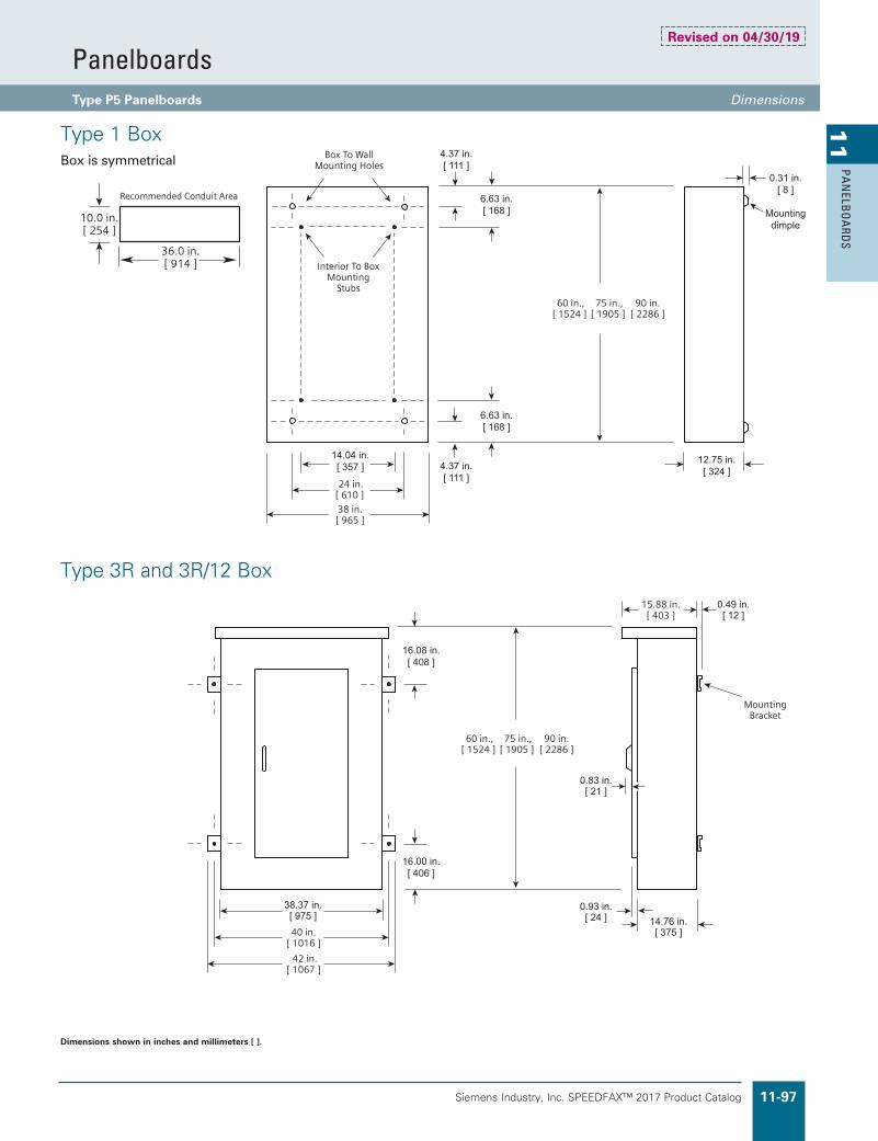
Siemens Industry, Inc. SPEEDFAX™ 2017 Product Catalog 11-97
11
PAN
ELBO
ARD
S
4.37 in.[ 111 ]
4.37 in.[ 111 ]
16.08 in.[ 408 ]
16.00 in.[ 406 ]
6.63 in.[ 168 ]
6.63 in.[ 168 ]
12.75 in.[ 324 ]
0.31 in.[ 8 ]
Mountingdimple
14.04 in.[ 357 ]
0.49 in.[ 12 ]
14.76 in.[ 375 ]
38.37 in.[ 975 ]
0.83 in.[ 21 ]
0.93 in.[ 24 ]
Dimensions shown in inches and millimeters [ ].
Type 1 BoxBox is symmetrical
Type 3R and 3R/12 Box
4.37 in.[ 111 ]
4.37 in.[ 111 ]
16.08 in.[ 408 ]
16.00 in.[ 406 ]
6.63 in.[ 168 ]
6.63 in.[ 168 ]
12.75 in.[ 324 ]
0.31 in.[ 8 ]
Mountingdimple
14.04 in.[ 357 ]
0.49 in.[ 12 ]
14.76 in.[ 375 ]
38.37 in.[ 975 ]
0.83 in.[ 21 ]
0.93 in.[ 24 ]
PanelboardsType P5 Panelboards Dimensions
Revised on 04/30/19

Siemens Industry, Inc. SPEEDFAX™ 2017 Product Catalog11-98
11
PAN
ELB
OA
RDS
PanelboardsCircuit Breaker / Column Type General
�Connector ranges indicated do not apply to all main breaker types. Refer to molded case circuit breaker standard pressure wire connectors in the breaker section of this catalog for the wire ranges for a specific breaker frame.
Type C1240 Volts AC Maximum 250 Ampere Mains 250 Ampere Maximum Branch UL Short Circuit Rating — 200,000 IR MaximumBranch Breaker Symmetrical Interrupting RatingBased on Underwriters’ Test Procedure
Type C2480Y/277 Volts AC Maximum 250 Ampere Mains 250 Ampere Maximum Branch UL Short Circuit Rating — 100,000 IR MaximumMeets NEC wire bending requirement, section 312–6.
PanelboardsListed by Underwriter’s Laboratories, Inc., under “Panelboards” File #E2269.
Meets Federal Specification W–C375B/Gen.
Service240 Volts Maximum. 1-Phase, 3-Wire, or 3-Phase, 4-Wire.
Panelboards Fronts and DoorsStandard panelboards are furnished with trim with a flush door lock. All are factory assembled for ease of installation. Fronts are fabricated from code gauge steel and finished ANSI-61.
Main Breakers C1BL, BLH and HBL frame breakers are mounted horizontally. All other frames are mounted vertically.
Main Breakers C2BQD frame breakers are mounted horizontally. All other frames are mounted vertically.
Main Breaker ConnectorsAmpere Rating Connectors suitable for Cu or Al
100 (1) #14–1/0 AWG
125 (1) #4–1/0 AWG
225 (1) #6 AWG–300 kcmil
250 (1) #4 AWG–350 kcmil Al (1) #6 AWG–350 kcmil Cu
125 (1) #6 AWG–350 kcmil
250 (1) #6 AWG–350 kcmil
Main Lugs
C1 75⁄8" 48", 73", 85"* #14
C2 81⁄2" 48", 73", 85"* #14
Fronts
BoxesC1 — 75⁄8" wide, 53⁄4" deep.C2 — 81⁄2" wide, 53⁄4" deep.
Branch Breaker Side Gutters Circuit Side Gutter Type Breaker (inches)
C1 BL, BLH, HBL 3.505
C2 BQD 3.5
Weight–ApproximateTotal panelboard weight when filled with a normal quantity of breakers and accessories is: *About 3 lbs. per inch of box height.
Gauge Steel BoxesType Width Height Gauge Steel
C1 75⁄8" 48", 73", 85" #14
C2 81⁄2" 48", 73", 85" #14
For inches / millimeters conversion, see Application Data section.
*Note: Feed thru lugs and subfeed breaker not available for this height.

Siemens Industry, Inc. SPEEDFAX™ 2017 Product Catalog 11-99
11
PAN
ELBO
ARD
S
For inches / millimeters conversion, see Application Data section.
BL, BLH, HBL and BQD are horizontally mounted.All others vertically mounted.
�Interchangeable trip breakers such as FD6 and HFD6 cannot be back fed. Must be top feed only.
Main Lugs Only C1 240 Volts Maximum
MaximumPanelAmpere Rating
Maximum1-PoleCircuits
BoxHeight(inches)
208Y/120V 120/240V
3-Phase, 4-WireCatalog Number
1-Phase, 3-WireCatalog Number
12518 48 C1C18ML125CTS C1A18ML125CTS30 73 C1C30ML125CTS C1A30ML125CTS42 85 C1C42ML125CTS C1A42ML125CTS
25018 48 C1C18ML250CTS C1A18ML250CTS30 73 C1C30ML250CTS C1A30ML250CTS42 85 C1C42ML250CTS C1A42ML250CTS
Main Circuit Breaker C1 240 Volts Maximum
10018 48 C1C18BL100CTS C1A18BL100CTS30 73 C1C30BL100CTS C1A30BL100CTS42 85 C1C42BL100CTS C1A42BL100CTS
12518 48 C1C18E4125CTS C1A18E4125CTS30 73 C1C30E4125CTS C1A30E4125CTS42 85 C1C42E4125CTS C1A42E4125CTS
22518 48 C1C18QR225CTS C1A18QR225CTS30 73 C1C30QR225CTS C1A30QR225CTS42 85 C1C42QR225CTS C1A42QR225CTS
25018 48 C1C18FX250CTS C1A18FX250CTS30 73 C1C30FX250CTS C1A30FX250CTS42 85 C1C42FX250CTS C1A42FX250CTS
Main Lugs Only C2 480Y/277 Volts Maximum
MaximumPanelAmpere Rating
Maximum1-PoleCircuits
BoxHeight(inches)
480Y/277V
3-Phase, 4-WireCatalog Number
12518 48 C2E18ML125CTS30 73 C2E30ML125CTS42 85 C2E42ML125CTS
25018 48 C2E18ML250CTS30 73 C2E30ML250CTS42 85 C2E42ML250CTS
Main Circuit Breaker C2 480Y/277 Volts Maximum
10018 48 C2E18BD100CTS30 73 C2E30BD100CTS42 85 C2E42BD100CTS
12518 48 C2E18E4125CTS30 73 C2E30E4125CTS42 85 C2E42E4125CTS
22518 48 C2E18FX225CTS30 73 C2E30FX225CTS42 85 C2E42FX225CTS
25018 48 C2E18FX250CTS30 73 C2E30FX250CTS42 85 C2E42FX250CTS
Alternate Main Breaker Selection C1
AmpereRating
BreakerType
MaximumInterruptingRating (KA)
CatalogNumber Available Trip Values
100BL 10 BL 50, 60, 70, 80, 90, 100BLH 22 LH 50, 60, 70, 80, 90, 100HBL 65 HL 50, 60, 70, 80, 90, 100
125ED4 65 E4 50, 60, 70, 80, 90, 100, 110, 125HED4 100 H4 50, 60, 70, 80, 90, 100, 110, 125HHED6 100 HA 50 (3-pole only)
225 QR2 10 QR 100, 110, 125, 150, 175, 200, 225
225FXD6 65 FX 70, 80, 90, 100, 110, 125, 150, 175, 200, 225HFD6 100 HF 70, 80, 90, 100, 110, 125, 150, 175, 200, 225
250FXD6 65 FX 250HFD6 100 HF 250
PanelboardsCircuit Breaker / Column Type Selection
Product Category PBSB
Revised on 05/15/18

Siemens Industry, Inc. SPEEDFAX™ 2017 Product Catalog11-100
11
PAN
ELB
OA
RDS
PanelboardsCircuit Breaker / Column Type Selection
�No increase in box height. Space is already built into C1 panel.
�BL, BLH, HBL and BQD are horizontally mounted.All others vertically mounted.
Interchangeable trip breakers such as FD6 and HFD6 cannot be back fed. Must be top feed only.
ED6/CED6 2-pole limited amps available (20-50A)
Alternate Main Breaker Selection C2Ampere Breaker Catalog Rating Type IR Number Available Trip Values100 BQD 14 BD 50, 60, 70, 80, 90, 100 ED4 18 E4 50, 60, 70, 80, 90, 100, 110, 125125 ED6 25 E6 50, 60, 70, 80, 90, 100, 110, 125 HED4 42 H4 50, 60, 70, 80, 90, 100, 110, 125 HHED6 65 HA 50 (3-pole only)
225 FXD6 35 FX 70, 80, 90, 100, 110, 125, 150, 175, 200, 225 HFD6 65 HF 170, 80, 90, 100, 110, 125, 150, 175, 200, 225
250 FXD6 35 FX 250 HFD6 65 HF 250
Branch Breaker Selection C1
BreakerType
AvailableAmpereRating
AvailabilityMaximum InterruptingRating (kA)
1-Pole 2-Pole 3-Pole 120V 120/240V 240V
BL (120V)15, 20, 30, 40, 50, 60 u u u — 10 —70 u u u — 10 —70, 80, 90, 100 — u u — 10 —
BL (HID) 15, 20, 30 u u — — — —
BLF (GFCI)15, 20, 30 u u — 10 — —40, 50, 60 — u — 10 — —
BLE (EQGFI) 15, 20, 30 u u — 10 — —BGL (SWN) 15, 20, 30 — u u 10 — —
BLR (240V)15, 20, 30, 40, 50, 60 — u — — — 1070, 80, 90, 100 — u — — — 10
BLH (120V)15, 20, 30, 40, 50, 60 u u u — 22 —70 u u u — 22 —70, 80, 90, 100 — u u — 22 —
BLHF (GFCI)15, 20, 30 u u — — 22 —40, 50, 60 — u — — 22 —
HBL15, 20, 30, 40, 50 u u u — 65 6560, 70, 80, 90, 100 — u u — 65 65
Subfeed Breakers — Limit One Per Panel C1 (Not available for 42 circuit panels)
ED415, 20, 30, 40, 50, 60, 70, 80, 90, 100 —– u u — — 65110, 125 —– u u — — 65
HED415, 20, 30, 40, 50, 60, 70, 80, 90, 100 —– u u — — 65110, 125 —– u u — — 100
HHED6 15, 20, 30, 40, 50 (3-pole only) —– — u — — 100QR2 100, 110, 125, 150, 175, 200, 225 —– u u — — 10FXD6 70, 80, 90, 100, 110, 125, 150, 175, 200, 225, 250 —– u u — — 65HFD6 70, 80, 90, 100, 110, 125, 150, 175, 200, 225, 250 —– u u — — 100
Branch Circuit Breakers C2
BreakerType
AvailableAmpereRating
AvailabilityMaximum InterruptingRating (kA)
1-Pole 2-Pole 3-Pole 277V 480/277V 480V
BQD15, 20, 30, 40, 50, 60 u u u 14 14 —70, 80, 90, 100 u u u 14 14 —
Subfeed Breakers — Limit One Per Panel C2 (Not available for 42 circuit panels)
ED415, 20, 30, 40, 50, 60, 70, 80, 90, 100 —– u u — 18 18110, 125 —– u u — 18 18
ED6 15, 20, 30, 40, 50, 60, 70, 80, 90, 100 —– u u — — 25110, 125 —– u u — — 25
HED415, 20, 30, 40, 50, 60, 70, 80, 90, 100 —– u u — — 42110, 125 —– u u — — 42
FXD6 70, 80, 90, 100, 110, 125, 150, 175, 200, 225, 250 —– u u — — 35HFD6 70, 80, 90, 100, 110, 125, 150, 175, 200, 225, 250 —– u u — — 65
Product Category PBSB
Revised on 05/15/18

Siemens Industry, Inc. SPEEDFAX™ 2017 Product Catalog 11-101
11
PAN
ELBO
ARD
S
Type C1/C2When required, special constructions or additions to standard panelboards may be specified for factory-assembled column panelboards.
Column ExtensionAvailable in various standard lengths, extensions are 51⁄4 inches deep and 7 inches wide.
Description
Feed-Thru Lugs Cu Neutral LugsCu main Lugs 125ACu main Lugs 250A
Interior Modifications
Box Sizing ChartCertain modifications such as subfeed breakers and feed-thru lugs require additional unit space. Use this chart to determine proper enclosure size.
Box Height Panel Configuration (inches)
All MLO 18 Circuit 48 All MLO 30 Circuit 73 All MLO 42 Circuit 85
All MLO 18 Circuit with feed-thru lugs 73 All MLO 30 Circuit with feed-thru lugs 85
All MLO 18 Circuit with subfeed breaker 73 All MLO 30 Circuit with subfeed breaker 85
All Main Breaker 18 Circuit 48 All Main Breaker 30 Circuit 73 All Main Breaker 42 Circuit 85
All Main Breaker 18 Circuit with feed-thru lugs 73 All Main Breaker 30 Circuit with feed-thru lugs 85
All Main Breaker 18 Circuit with subfeed breaker 73 All Main Breaker 30 Circuit with subfeed breaker 85
Height (inches) Catalog Number
14 LXX-14 20 LXX-20 26 LXX-26 32 LXX-32 38 LXX-38 41 LXX-41 44 LXX-44 53 LXX-53 56 LXX-56 62 LXX-62 65 LXX-65 68 LXX-68 74 LXX-74 80 LXX-80 86 LXX-86
Description Catalog Number
Top Mount LXXP-T Front Mount LXX50-F
Pull BoxesTwo styles of pull boxes are available, top and front mounted. When the panel and its extensions are mounted in a structural WF beam a front mounted pull box is required. When the panels are surface mounted, a top mounted pull box may be used. Provisions are made so that the neutral bar may be mounted in the pull box when required. (Front mounted pull box dimensions are 14" H. X 20" W.)
For inches / millimeters conversion, see Application Data section.
Must be ordered as a manual line. Includes 50" extension.
Description
Gasketed Metal Card HolderWelded Metal Card Holder Nameplate Al Ground BarCu Ground BarInsulated Al Ground BarInsulated Cu Ground Bar
Box Modifications
PanelboardsCircuit Breaker / Column Type, Modifications and Additions Selection�
Product Category PBSB
Breaker Kits and Accessories
Kit Number Description Contents
MBKQRC1FK C1 Filler for QR in Main position 1PH or 3PH
Kit contains all cover plates necessary to change from QJ to QR both 2 and 3-pole breakers.

Siemens Industry, Inc. SPEEDFAX™ 2017 Product Catalog11-102
11
PAN
ELB
OA
RDS
Telephone and Equipment Cabinets: Conform to requirements of Underwriters’ Laboratories, Inc., for all cabinets and boxes bearing their label. Surface and Flush enclosures: box and front constructed of code-gauge steel, box galvanized and front only finished with light gray, ANSI-61. Cabinets provided without backboards.
Boxes: Standard construction has blank end walls, without knockouts.
Fronts: Siemens Fas Latch fronts feature concealed hinges and fastening screws. Match P1 and P2 Panels in appearance. Two locks supplied on doors more than 51 inches high.
Dimensions
For inches / millimeters conversion, see Application Data section.
Add S for Surface, F for Flush.
CabinetsDimensions (inches) Surface Mount
Catalog NumberFlush MountCatalog NumberHeight Width Depth
With FAS Latch Front29 20 5.75 TCS29B TCF29B41 20 5.75 TCS41B TCF41B47 20 5.75 TCS47B TCF47B59 20 5.75 TCS59B TCF59B
PanelboardsTelephone and Equipment Cabinets Selection/Dimensions
Product Category PBSB

Siemens Industry, Inc. SPEEDFAX™ 2017 Product Catalog 11-103
11
PAN
ELBO
ARD
S
Dimensions
H W D Catalog Number
23 20 5.75 RC(1)23B
23 24 5.75 RCW(1)23B
Replace (1) with ”S” for surface applications and ”F” for flush applications.
Application (See individual panel sections for application information)
Remote Control Switch Modification Description
Auxiliary Contacts (Mounted Not Wired) Ea.
2-Wire Control (add 6" to panel height.)
Control Power Transformer Size VA 0,1 50 2 75 3 150 4 250
AmpereRating
ASCO #920Mechanically held
ASCO #911 — Mechanically held remote control switch suitable for all classes of loads (Total system loads). Voltage rated to 480V AC, UL listed.
Siemens LENElectrically Held
2-Pole 3-Pole 3-Pole 2-Pole 3-Pole20 — — — — —30 u u — — u
60 u u — — u
75 u u — — —100 u u u — u
150 u u u — —200 u u — — u
225 u u — — —260 — — u — —300 — — u — —400 — — u — —600 — — u — —800 — — u — —
1000 — — u — —1200 — — u — —
u = available configurations
Includes Fas latch trim and steel mounting pan. If 2 or more cabinets are to be stackedn order (no extra charge for connecting hardware).
Available in P4 or P5 only.
Customer Relay Cabinets
PanelboardsEnclosure Modifications Selection
Product Category PBSB

Siemens Industry, Inc. SPEEDFAX™ 2017 Product Catalog11-104
11
PAN
ELB
OA
RDS
Standard Enclosures Made From Special Materials — Type P1, P2, P3
14GA 304 SS Front Grade (Brush Front) Front
Stainless Steel Options
* Stainless available only for Screw-to-Box, Hinge-to-Box, and Door-in-Door. All have piano hinges only.
**No special sizes. 20" and 24" wide only.
Description.
Conduit Hubs — Up to 1 1/2 in. Each 2 in. to 2 1/2 in. Each 3 in. Each
Miscellaneous
Painted Finish Set-up Charge Net . Box Only Alternate Color Trim
Devices Mounted On Interior-IncludesDevice, Mounting (Wired or Unwired)
Toggle Switch-SPST or 3-way; 15A, 277 V Maximum
Pilot Light-General Purpose, Neon or Incandescent
Pushbutton
�Panels having doors over 48 in. high, 2 locks are standard.� Lighting panels only. Field must supply dimensional
information and panel orientation.
Front And Door Modifications Two Panels with Common Trim (14 GA only)
Note: For retro fit interiors and fronts into existing can, retro fit must match or exceed minimum height, width, and depth requirements of standard Type 1 enclosures.
Stainless Steel Additions to Enclosure Size (Type 1 Only)
Lighting Panel Distribution Panels
Width Order in 2" increments (30" max)
Order in 2" increments
Depth Order in 2" increments (10" max)
Order in 2" increments
Consult factory for dimension limitations.
PanelboardsModifications and Additions Selection
Product Category PBSB
Gauge Steel of Boxes/Fronts, Surface and Flush (see pgs. 11-6 & 11-7)Dimensions in Inches (mm) Gauge Steel
H W Box Front/Door Type
26-74 (660-1880) 20 (508) 16 14 Type 126-74 (660-1880) 20 (508) 16 16/14 Type 3R/1232-60 (813-1524) 20-36 (508-914) 14 14 Type 426-74 (660-1879) 20 (508) 14 14 Type 4X36-60 (914-1524) 30-36 (762-914) N/A N/A Type 4X Non-Metallic
16 Gauge is Standard (14 Gauge & 12 Gauge are optional) 15 Gauge Steel Can with 14 Gauge Door or Similar Approved Construction No Optional Gauge available 304SS 14 Gauge Std., 316SS 14 Gauge optional Sizes do not match Standard Enclosure Sizes - See Table P1-21 - material is non-metallic - No Gauge Specified. FAS-Latch is 14 GA only.
Screw-to-Box, Hinge-to-Box, Door-in-Door (14 GA Std./12 GA Std. or 10 GA Optional) STB/HTB/DND with Piano Hinge (14 GA Std./12 GA Optional)
Revised on 04/11/17

Siemens Industry, Inc. SPEEDFAX™ 2017 Product Catalog 11-105
11
PAN
ELBO
ARD
S
Molded Case Switches
(Non-Automatic Circuit Interrupters)
When Molded case switches are substituted for thermal breakers deduct from the installed thermal breaker price:
Ampere Breaker Availability
Rating Frame 3-Pole 2-Pole
100 ED2 u u ED4 u u ED6 u u
225 QR2 u u
250 FXD6 u u
400 JXD2 u u JXD6 u u
600 LXD6 u u
800 MD6 u u
1200 ND6 u —
Conduit Enclosing Shield (Panel Skirts)Sheet metal to cover conduits above or below a standard panelboard box.
Panel Skirts Standard Configurations
3 Sides Open Back 4 Sides Screw Front
Skirt Length Width Depth
8, 9, 11, 12, 14, 17, 18, 23, 25
20.00 5.7526, 27, 28, 29, 30, 31, 32, 33, 34, 35, 3637, 38, 39, 40, 41, 42, 43, 448, 9, 11, 12, 14, 17, 18, 23, 25
24.00 7.7526, 27, 28, 29, 30, 31, 32, 33, 34, 35, 3637, 38, 39, 40, 41, 42, 43, 44
Available only as a main switch for non-service equipment applications. Not available for branch devices.
PanelboardsCircuit Breaker Accessories and Modifications Selection
Product Category PBSB
Notes: A) 4-sided skirts have standard Part Numbers (not catalog numbers).B) 3-sided skirts are ordered as Custom in COMPAS. C) Order in COMPAS with interior when possible. D) If ordered separate from interior, use a manual line in COMPAS. E) Must note if Top Entry or Bottom Entry required.
Revised on 04/30/19

Siemens Industry, Inc. SPEEDFAX™ 2017 Product Catalog11-106
11
PAN
ELB
OA
RDS
QuickShip™All SQSCP configurations of the standard NEMA 1 enclosure can be specified for shipment within 10 business days of order when specified.
Mains
MLO (Main Lug Only)
Fused disconnect switch
Non-fused disconnect switch
Assembly SCCRs200kA, 100kA or 50kA AC, 100kAor 20kA@125Vdc
Voltage ratingsApplicable on any 600Vac or less, or 125Vdc
or less systems
Bus amperages 400A, 225A, 200A, 100A, 60A or 30A
Branch circuits
Circuits: 18, 30 or 42*
Amps: Up to 100A
Type: 1-, 2- and 3-Pole
Panels
Feed: top & bottom
Mounting: surface or flush
Door/Trim: regular or door-in-door
NEMA Ratings: 1 & 3R.Other ratings available, consult factory.
Through-lugs& loadsidedisconnect
Feed-Through: single and double
Sub-Feed
Feed/Sub-Through
Fused loadside disconnect,(up to 1/2 of main amp rating)
Neutrals 200A, 400A and 800A unbonded and bonded
Grounds Non-isolated or isolated
Enclosure sizesStandard size panelboard(20” W x 5¾” D x 33”- 69” H)*
Spare fuses Spare fuse compartment holds up to six fuses
Options
Surge protection device (SPD) for highand low energy transients.*
Depending on configuration. 125Vdc rating applicable to only 80 amp or less CCPBs on MLO panels only.
PanelboardsQuik-Spec™ Coordination Panelboard Specifications
*Factory installed SPD options
System & Voltage Catalog Number
Discharge Current
Response Time SCCR
Data Sheet Number
Nominal (In)
Maximum (Imax)
Single-phase, 120/240 BSPM2240S3G
20 kA 40 kA ≤25 ns 200 kA
2150Three-phase Wye, 208/120 BSPM4208WYNG 2152Three-phase Wye, 480/277 BSPM4480WYNG 2152Delta, 480 BSPM3480DLG 2151

Siemens Industry, Inc. SPEEDFAX™ 2017 Product Catalog 11-107
11
PAN
ELBO
ARD
S
Catalog Symbol: SQSCP4
Description
Panelboards for commercial/industrial branch or service entrance applications on systems up through 600Vac.
The SQSCP is specifically designed to address the NEC® Selective Coordination Requirements for Emergency, Legally Required Standby, Healthcare Essential Electrical and Critical Operation Power Systems (COPS) per NEC® 700.28, 701.27, 645.27 and 708.54. Not for applications requiring AFCI protected circuits. The SQSCP is configured to order for the application. To confirm availability of options and constructions, contact your Siemens distributor.
Ratings
Volts: 600Vac (or less), 125 VdcAmps: 30, 60, 100, 200, 225, 400ASCCR: 20kA or 100kA @ 125Vdc–See panelboard short circuit ratings table for AC ratings.
Agency informationb UL 67–Standard for panelboards
b UL 50/UL 50E–Enclosures for electri-cal equipment
b CSA 22.2, No. 29-M1989– Panelboards and encl. panelboards
b UL listed, class CTL panelboard (meets editions of the NEC prior to 2008 with regard to the NEC® 408.15 limit of 42 overcurrent devices per panel)
b UBC and CBC Seismic Qualified and IBC Approved
Panelboard Short-circuit Current Ratings
SCCR
AC main options DC
Main lug only(MLO)
70-200A main disc. no fuses
or w/ Class J fuses225-400A main disc. no fuses
or w/ Class J fusesSCCP_CF main disc. (60A)
Main lug only(MLO)
High 200kA 200kA 100kA 200kA 100kA
Std. 50kA 50kA 50kA 50kA 20kA
Class J, T or RK1 fuses upstream, max amps = panel amps. CUBEFuse® disconnect
Main optionsb Main lug only (MLO)
b Fused main disconnect
b Non-fused main disconnect
Branch disconnect optionsb 1-, 2-, and 3-pole 15, 20, 30, 40, 50,
60, 70, 90, and 100A rejecting branch disconnects (see table for details).
Branch ampacity on 125Vdc panels limited to SCCPB 80A or less.
Branch circuit positionsb 18, 30 and 42
Neutral optionsb Unbonded and bonded 200A, 400A
and 800A
Ground optionsb Isolated and non-isolated
Enclosuresb NEMA 1 and NEMA 3R. Other ratings
available. Consult factory.
Spare fuse compartmentb Six space spare fuse compartment
standard on all models
PanelboardsQuik-Spec™ Coordination Panelboard Specifications

Siemens Industry, Inc. SPEEDFAX™ 2017 Product Catalog11-108
11
PAN
ELB
OA
RDS
I – CCPB Branch DisconnectsPoles Ampacity Part No.
1-pole15A, 20A, 30A, 40A, 50A, 60A, 70A, 90A, 100A
SCCPB-1-(amp)CF
2-pole SCCPB-2-(amp)CF
3-pole SCCPB-3-(amp)CF
J – CUBEFuse® Fuses
For CCPB Part No.Non-indicating PartNo. STCF(amps)RN
Indicating Part No. STCF(amps)
SCCPB-(# of poles)-15CFSTCF1RN, STCF3RN,STCF6RN, STCF10RN,
STCF15RN
STCF6STCF10STCF15
SCCPB-(# of poles)-20CF STCF17-1/2 RNSTCF20RN
STCF17-1/2STCF20
SCCPB-(# of poles)-30CF STCF25RNSTCF30RN
STCF25STCF30
SCCPB-(# of poles)-40CF STCF35RNSTCF40RN
STCF35STCF40
SCCPB-(# of poles)-50CF STCF45RNSTCF50RN
STCF45STCF50
SCCPB-(# of poles)-60CF STCF60RN STCF60
SCCPB-(# of poles)-70CF STCF70RN STCF70
SCCPB-(# of poles)-90CF STCF80RNSTCF90RN
STCF80STCF90
SCCPB-(# of poles)-100CF STCF100RN STCF100
CCPB disconnect can accept CUBEFuses® with amp ratings less than or equal to the amp rating of the SCCPB disconnect. 1A indicating CUBEFuse® not available. Correct fit with SCCPB disconnect requires indicating CUBEFuse® with date code R38 or later.
J
I
Fuse and disconnect performance data
For details and specifications,access the following data sheets online atwww.usa.siemens.com/panelboards
CUBEFuse® Specifications Catalog Symbols
STCF_ (6-100A Indicating version)STCF_RN (1-100A Non-indicating version)
Description
The CUBEfuse® is a finger-safe, dual-element, time delay UL Class CF power fuse with Class J fuse electrical performance charcteristics. 10 Seconds minimum operating time at 500% rated current.
Ratings
Volts: 600Vac/300VdcAmps: 1-100 (non-indicating version) 6-100 (indicating version)IR: 300kA RMS Sym. (UL) 200kA RMS. Sym (CSA) 100kA DC (UL & CSA)
Agency Informationb UL Listed Special Purpose Fuse: Guide JFHR,
File E56412
b CSA Certified Fuse: Class 1422- 02, File 53787
b CE compliance for the European Union low voltage directive
Other Ratings/Specifications
Watts Loss at rated current: STCF30: 3.99W STCF60: 6.23W STCF100: 9.51W
Operating and Storage Temperature Range
14 to 149°F(-10 to 65°C)
Material Specificationsb Case: Glass filled PES (Polyethersulfone)
b Terminals: Copper alloy
b Terminal plating: Electroless tin
b Indicator lens: PES (Polyethersulfone)
(indicating version only)
b Indicator: Energetic chemical
CUBEFuse®, Low-Peak®, Quik-Spec™, QuickShip™, and easyID™ are valuable trademarks of Cooper Industries in the United States and other countries.
PanelboardsSCCPB Branch Disconnects, CUBEFuse® Replacement�parts�and�performance�data

Siemens Industry, Inc. SPEEDFAX™ 2017 Product Catalog 11-109
11
PAN
ELBO
ARD
S
SCCPB Horsepower Ratings
SCCPB DisconnectAmpRating
HP Rating @ Vac
120 240 480 600
SCCPB-(poles)-15CF 15 0.5 3 5 7.5
SCCPB-(poles)-20CF 20 0.75 3 7.5 10
SCCPB-(poles)-30CF 30 1.5 5 15 10
SCCPB-(poles)-40CF 40 2 7.5 20 10
SCCPB-(poles)-50CF 50 3 7.5 20 10
SCCPB-(poles)-60CF 60 3 7.5 20 10
SCCPB-(poles)-70CF 70 3 15 30 40
SCCPB-(poles)-90CF 80 5 20 40 50
SCCPB-(poles)-100CF 100 5 20 50 50
Branch Disconnects
SCCPB
Part No. PolesFuse AmpRange
Max.SCCBPAmp.
Non-indicating Fuses (Standard)
IndicatingFuses (Opt’l)
SCCPB-1-15CF 1
1-15 15STCF1RN, STCF3RN,STCF6RN, STCF10RN, STCF15RN
STCF6STCF10STCF15
SCCPB-2-15CF 2
SCCPB-3-15CF 3
SCCPB-1-20CF 1
17.5-20 20 STCF17-1/2 RNSTCF20RN
STCF17-1/2STCF20SCCPB-2-20CF 2
SCCPB-3-20CF 3
SCCPB-1-30CF 1
25-30 30 STCF25RNSTCF30RN
STCF25STCF30
SCCPB-2-30CF 2
SCCPB-3-30CF 3
SCCPB-1-40CF 1
35-40 40 STCF35RNSTCF40RN
STCF35STCF40SCCPB-2-40CF 2
SCCPB-3-40CF 3
SCCPB-1-50CF 1
45-50 50 STCF45RNSTCF50RN
STCF45STCF50SCCPB-2-50CF 2
SCCPB-3-50CF 3
SCCPB-1-60CF 1
60 60 STCF60RN STCF60SCCPB-2-60CF 2
SCCPB-3-60CF 3
SCCPB-1-70CF 1
70 70 STCF70RN STCF70SCCPB-2-70CF 2
SCCPB-3-70CF 3
SCCPB-1-90CF 1
80-90 90 STCF80RNSTCF90RN
STCF80STCF90
SCCPB-2-90CF 2
SCCPB-3-90CF 3
SCCPB-1-100CF 1
100 100 STCF100RN STCF100SCCPB-2-100CF 2
SCCPB-3-100CF 3
SCCPB disconnect can accept CUBEFuses® with amp ratings less than or equal to the amp rating of the SCCPB disconnect.
Correct fit with SCCPB disconnect requires indicating CUBEFuses® with date code R38 or later.
PanelboardsSCCPB Branch Disconnects, CUBEFuse® Specifications

Siemens Industry, Inc. SPEEDFAX™ 2017 Product Catalog11-110
11
PAN
ELB
OA
RDS
NEMA 1b Flush or surface mount.b Galvanized steel with removable end
walls –blank or with knockouts to order.b Box sizes: 20” W x 5.75” D x 33”, 50”,
59” or 69” H (510 W x 145 D x 838, 1270, 1500 or 1753mm H). Box can be rotated 180° to accommodate conduit feed.
b Enclosure and chassis mounting instruc-tions are found in supplied literature.
b Chassis mounts directly onto studs in the enclosure.
b Trim finished with gray powder coat paint over phosphatized steel (ANSI 61).
b Door and door-in-door configurations with locks.
b Door locks use key #2A1910-2.b Circuit directory card is located on the
inside of the door.b Trim screws are concealed.
AC Voltages1 phase, 2 wireb 120V 1 phase, 2 wireb 240V 1 phase, 2 wire
1 phase, 3 wireb 120/240V 1 phase, 3 wire
1 phase, 2 wire, Wyeb 277V 1 phase, 2 wire
1 phase, 2 wire, Deltab 480V 1 phase, 2 wire
1 phase, 3 wire, Deltab 240/480V 1 phase, 3 wire
3 phase, 4 wire, Wyeb 208Y/120V 3 phase, 4 wireb 480Y/277V 3 phase, 4 wireb 600Y/347V 3 phase, 4 wire
3 phase, 4 wire, Deltab 240/120V 3 phase, 4 wireb 480/240V 3 phase, 4 wire
3 phase, 3 wire, Deltab 240V, 3 phase, 3 wireb 480V, 3 phase, 3 wireb 600V, 3 phase, 3 wireb 240V, 3 phase, 3 wire,
grounded Bb 480V, 3 phase, 3 wire,
grounded Bb 600V, 3 phase, 3 wire,
grounded B
1 phase, 3 wire, Wyeb 208Y/120V 1 phase, 3 wireb 480Y/277V 1 phase, 3 wire
DC voltage1 phase, 2 wireb 125Vdc, 2 wire
(Up to 125Vdc, MLO optiononly, SCCPB 40A or less.)
NEMA 3Rb Surface mount only.b Finished with gray powder coat paint
over phosphatized steel (ANSI 61).b Bottom feed only, no knockoutsb Box sizes: 20” W x 7.7” D x 34.5”,
51.5”, 60.5” or 70.5 H (510 W x 195 D x 876, 1310, 1535 or 1791mm H).
b Enclosure and chassis mounting instruc-tions are found in supplied literature
b Chassis mounts directly onto studs in the enclosure.
b Gasketed door has vault handle with lock.
b Door locks use key #2A1910-1.b Circuit directory card is located on the
inside of the door.
Busing
Tin-plated copper with sufficient cross section to meet UL 67 tem-perature rise requirements.
Distributed 1- & 3-phase busingAll SCCPB branch disconnects can be mounted inany branch circuit position.
A B
N
C
A
BC
AB
N
C
A
BNC
A
BC
A
BC
B
N
C
A
N +125Vdc
Single-phase Three-phase
PanelboardsEnclosure/System Types, AC & DC Voltages

Siemens Industry, Inc. SPEEDFAX™ 2017 Product Catalog 11-111
11
PAN
ELBO
ARD
S
NEMA 1 and 3R Enclosure Dimensions
Encl. Type Encl. HeightDimensions (inches)H HC MH CH DH RH SH DW D
NEMA 1
33 33.0 N/A 29.0 26.0 28.9 25.0 2.0 20.0 5.7
50 50.0 N/A 43.0 40.0 37.9 39.0 3.5 20.0 5.7
59 59.0 N/A 52.0 49.0 46.9 48.0 3.5 20.0 5.7
69 69.0 N/A 62.0 59.0 56.9 58.0 3.5 20.0 5.7
NEMA 3R
33 33.0 34.5 35.5 26.0 28.9 25.0 2.0 20.0 6.3
50 50.0 51.5 52.5 40.0 37.9 39.0 2.0 20.0 6.3
59 59.0 60.5 61.5 49.0 46.9 48.0 2.0 20.0 6.3
69 69.0 70.5 71.5 59.0 56.9 58.0 2.0 20.0 6.3
Available panelboard configurationsBased on enclosure height, panel amp rating and number of branch circuit positionsEncl. height (inches) Panel amp rating
Branch positions Available configurations
33” 30–20018 · Main lug only, with or without feed-through lugs
· Non-fused disconnect, no loadside options
30 · Main lug only, no loadside options
50”
30–60
18 · 30 through 60A fused main disconnect with or without feed-through lugs or TVSS device
30 · 30 through 60A fused main disconnect with or without feed-through lugs or TVSS device
42 · 30 through 60A fused main disconnect with or without feed-through lugs or TVSS device
70–20018 · 70 through 200A fused main disconnect with or without feed-through lugs or TVSS device
30 · 70 through 200A fused disconnect with or without feed-through lugs
30–200
18 · Main lug only with TVSS device· Non-fused disconnect, with feed-through lugs or TVSS device
30 · Main lugs only, with feed-through lugs or TVSS device· Non-fused disconnect, with or without feed through lugs
42 · Main lug only, with or without feed-through lugs or TVSS device· Non-fused disconnect, with or without feed-through lugs
225–400A18 · Main lug only, with ot without feed through lugs or TVSS device
· Non-fused disconnect, with or without feed-through lugs
30 · Main lug only, with or without feed-through lugs
59”
70–20030 · 70 through 200A fused main disconnect, with TVSS device
42 · 70 through 200A fused main disconnect with or without feed-through lugs or TVSS device
30–200 42 · Non-fused disconnect with TVSS device
225–400A
18· Main lug only with loadside disconnect· Non-fused disconnect, with TVSS device· 225 through 400A fused disconnect with or without feed-through lugs or TVSS device
30 · Main lug only, with TVSS device· 225 through 400A fused disconnect, with no loadside options
42 · Main lug only, with or without feed-through lugs or TVSS device· Non-fused disconnect, with no loadside options
69” 225–400A
18 · Non-fused disconnect, with loadside disconnect
30 · Main lug only with loadside disconnect· 225 through 400A fused disconnect with feed-through lugs or TVSS device
42 · Non-fused disconnect, with or without feed through lugs or TVSS device· 225 through 400A fused main disconnect, with or without feed-through lugs or TVSS device
PanelboardsDimensions and Panelboard Configurations

Siemens Industry, Inc. SPEEDFAX™ 2017 Product Catalog11-112
11
PAN
ELB
OA
RDS
NEMA 1 Enclosuresand Interior
NEMA 3R EnclosuresInterior same as NEMA 1
SH 2.0
MH
Top End Wall (No Knockouts)
Bottom End Wall (No Knockouts)
Box Interior Same as NEMA 1
H
Side View
D
7.68
0.65
DETAIL B SCALE 1 : 4
0.2 0.5
Front View
B
HC
0.62X
13.0DW
Blank Endwall
Side View of Box
D
H
0.25 Mounting Hole Emboss
Neutral
Ground
Box with Interior
Spare Fuse Compartment
A
DH
RHCH
20.0
2.016.0
SH
MH
11.3
Enclosures Available with 2 Blank, 2 Knockout, or 1 Each Endwall
Concentric KO21 (7/8, 1-1/8) (1-3/4, 2, 2-1/2, 3, 3-5/8, 4-1/8)
Concentric KO
Knockout Endwall7.4
1.5
2.93.1
DETAIL A
0.3
2.21.1
0.5
DWSurface Mount
DW + 3.0Flush Mount
Front View(Door in Door Option Shown on Right)
Door Lock
DWSurface Mount
HSurface Mount
H + 3.0Flush Mount
DW + 3.0Flush Mount
PanelboardsNEMA 1 and NEMA 3R Dimensions

Siemens Industry, Inc. SPEEDFAX™ 2017 Product Catalog 11-113
11
PAN
ELBO
ARD
S
Current Limitation Curves
Time-Current Characteristic Curves–Average Melt
PanelboardsFuse Curves

Siemens Industry, Inc. SPEEDFAX™ 2017 Product Catalog11-114
11
PAN
ELB
OA
RDS
PanelboardsNotes