Martin O'Malley, Governor Anthony G. Brown, Lt. Governor ...
7/26/2019 Pandaros Digital Governor _ Special Instruction _ REHS2806 _ May 2006 _ PERKINS.pdf
http://slidepdf.com/reader/full/pandaros-digital-governor-special-instruction-rehs2806-may-2006-perkinspdf 1/48
REHS2806
15 May 2006
Special Instructioni02435096
Pandaros Digital Governor
Industrial Engine4006TRS Gas Engine4008 TRS Gas Engine4012-46ADiesel Engine4016-61ADiesel Engine
Table of Contents
Introduction ........................................................... 2System Overview .................................................. 3Description of System ........................................... 4Diagram of the Governor System ......................... 5Specification of Governor System ........................ 5
Current consumption of the governor ................ 5EMC Directives ................................................. 5
Setting for the Feedback ....................................... 6Setting the Feedback without the Service Tool ..... 10Configuration ........................................................ 10
Speed ................................................................ 10Droop/Isochronous ............................................ 11
External Input for Speed Control .......................... 11Single generator fixed speed ............................ 11Single generatorvariable speed ........................ 11
Parallel generator Heinzmann LSU/Sync ............. 11Parallel generator LSU/Sync ............................. 11
Changing the configuration of the governor .......... 11Single generator fixed speed ............................ 12
Single generator variable speed ........................... 13Droop ................................................................ 13
Droop ............................................................. 13DroopRefLo ................................................... 13DroopRefHi .................................................... 13
DroopSpeedRef ............................................. 13 ADC1 Type .................................................... 14 AnalogIn1_RefLo ........................................... 14 AnalogIn1_RefHi ........................................... 14 AnalogIn1_ErrorLow ...................................... 14 AnalogIn1_ErrorHigh ......................... ............ 14 AnalogIn1_Filter ............................................ 14
Parallel generator Heinzmann LSU/Sync ............. 15Parallel generator other LSU/Sync .................... 15
Load Control Settings ........................................... 16 ADC 1_Type ...................................................... 16
AnalogIn1_RefLow ............................................ 16 AnalogIn1_RefHigh ........................................... 16 AnalogIn1_ErrorLow ......................................... 16 AnalogIn1_ErrorHigh ......................................... 16LoadControlFactor and
LoadControlReference .................................... 17Synchronizer Settings ....................................... 17
ADC 2_Type .................................................. 17 AnalogIn2_RefLow ........................................ 17 AnalogIn2_RefHigh ....................................... 17 AnalogIn2_Err orLow ...................................... 18
AnalogIn2_ErrorHigh ..................................... 18SynchronFactor and SynchronReference ..... 18 Additional Programmable Parameters .............. 18Engine Configuration ......................................... 18
SpeedMin1 and SpeedMin2 .......................... 18SpeedMax1 and SpeedMax2 ........................ 18
Engine Stop ....................................................... 18Switch or Impulse .......................................... 18Close or Open ............................................... 18
Common Alarm ................................................. 18 Adjustment of PID parameters .............................. 18PID Maps .............................................................. 19Speed Ramps ....................................................... 20
Fixed Speed Ramp ........................................... 21
Programming example .................................. 21 Activation ....................................................... 21
Sectional Speed Ramp ......................................... 21Programming Example ...................................... 23
Activation ........................................................... 23System Wiring ....................................................... 23
External Connections Perkins Supplied Cable for Diesel Engines ................................................ 25
External Connections and the Connector for theControl Box for Diesel Engines ....................... 26
External Connections for Diesel Engines .......... 27Cable Sizes ....................................................... 27
Alternative Connections for Speed SettingInputs ............................................................... 27
Single or Parallel Generator Variable Speed .. 27Parallel Generator Heinzmann LSU/Sync ..... 28Parallel Generator other LSU/Sync ............... 29
Wiring Diagram for the Digital Control Box in IPEnclosure ........................................................ 30
Diagram for the Wiring Harness for 4006 and 4008Diesel Engines ................................................ 31
Diagram for the Wir ing for 4012 and 4016 DieselEngines ........................................................... 31
Diagram for the Wiring for 4006 and 4008 GasEngines ........................................................... 33
1
7/26/2019 Pandaros Digital Governor _ Special Instruction _ REHS2806 _ May 2006 _ PERKINS.pdf
http://slidepdf.com/reader/full/pandaros-digital-governor-special-instruction-rehs2806-may-2006-perkinspdf 2/48
Finding Faults .................................................... 35Test 1 ............................................................. 35Test 2 ............................................................. 35Test 3 ............................................................. 35Test 4 ............................................................. 35Test 5 ............................................................. 36Test 6 ............................................................. 36
The governor lever moves when cranking theengine but the engine will not start (DieselEngines only) ................................................... 36
Test 1 ............................................................. 36Test 2 ............................................................. 36Test 3 ............................................................. 37Test 4 ............................................................. 39Test 5 ............................................................. 39
Governor moves to maximum position when power supply is switched on. ..................................... 40
Test 1 ............................................................. 40Test 2 ............................................................. 40
The engine goes to overspeed after starting ..... 40Test 1 ............................................................. 40Test 2 ............................................................. 40Test 3 ............................................................. 41Test 4 ............................................................. 41
Test 5 ............................................................. 41The governor is not stable ................................. 41
Test 1 ............................................................. 41Test 2 ............................................................. 41Test 3 ............................................................. 42Test 4 ............................................................. 42Test 5 ............................................................. 42Test 6 ............................................................. 42Test 7 ............................................................. 42
Speed droops under load .................................. 43Test 1 ............................................................. 43Test 2 ............................................................. 43Test 3 ............................................................. 43Test 4 ............................................................. 43
The engine will not pull load .............................. 43Error Codes ....................................................... 44Error Memory .................................................... 47
Introduction
The Heinzmann Pandaros digital speed governor is installed to a Perkins 4000 Series engine.This Special Instruction gives an overview of thegovernor system and details of customer interfacerequirements.
The control system consists of the following
components:
• Control unit
• Actuator
• Setpoint adjusters
• Sensors
• Connection cables
The actuator is connected to the linkage of the fuelinjector on diesel engines in order to control theamount of fuel. The actuator is connected to thethrottle valve on gas engines in order to control theamount of fuel.
The control unit is engine mounted within an IP55enclosure.
2
7/26/2019 Pandaros Digital Governor _ Special Instruction _ REHS2806 _ May 2006 _ PERKINS.pdf
http://slidepdf.com/reader/full/pandaros-digital-governor-special-instruction-rehs2806-may-2006-perkinspdf 3/48
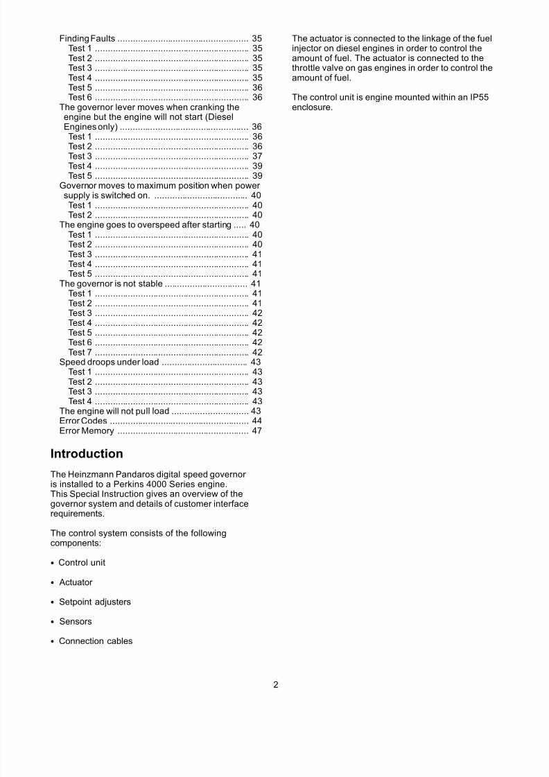
System Overview
g01216812Illustration 1
(1) Laptop computer (2) Control unit
(3) Run status(4) CAN Communication(5) DC - Desk displays(6) Governor errors(7) Stop/Run(8) Synchronizing(9) Load sharing(10) Voltage matching(11) Reactive load share
(12) Speed ramp(13) Load ramp
(14) Soft load transfer (15) Isochronous ramp(16) Power factor set(17) Mains parallel(18) Island parallel(19) Group synchronizing(20) Digital power control(21) Governor sensor (22) Actuator
3
7/26/2019 Pandaros Digital Governor _ Special Instruction _ REHS2806 _ May 2006 _ PERKINS.pdf
http://slidepdf.com/reader/full/pandaros-digital-governor-special-instruction-rehs2806-may-2006-perkinspdf 4/48
NOTICE Adjustments to the control unit may only be madeby an authorised Perkins representative equippedwith the necessary programmer. There are no user adjustments inside the box.
Description of System
The electronic control unit is the center of the system.There is a 16 bit microprocessor in the control unit.The processor operates the program which controlsthe system. The program which controls the systemis stored in a FLASH-EPROM section of the memory. The control unit compares the actual engine speedthat is measur ed by the magnetic pickup on theflywheel with the desired speed of the engine. Thecontrol unit helps to drive the actuator and the inputof the fuel to the engine so that the actual enginespeed matches the desired engine speed.
Boost pressure for the engine is measured and usedin order to control fueling for optimum performanceand minimum smoke.
Additional inputs are available for the measurementof the following data:
• Engine temperature
• Fueling control against engine temperature
• Connection of additional automatic load sharing
• Synchronizing equipment
A PC program with special interface cable is used for initial setting of the parameters for the governor andoptimizing the system and for finding faults.
A CAN bus is available for connecting to digitalsharing of loads and synchronizing equipment andfuture monitoring of the system.
If a sensor or the actuator is at fault, an alarm isissued and there will be an engine shutdown. Internalerrors get detected also and the errors will be storedas all other failures. All failures can be red with anexternal PC.
To optimize the dynamics for every operating point,the parameters for the PID are corrected. Theparameters depend on the engine speed, the enginetemperature and load on the engine via stabilitymaps. Proportional gain values, Integral gain valuesand gain values for the Derivative can be modifiedfrom the service tool.
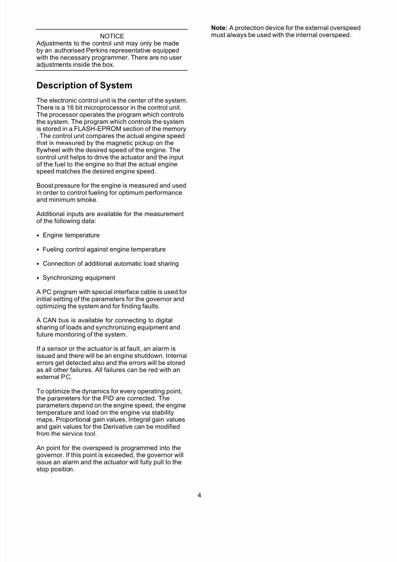
An point for the overspeed is programmed into thegovernor. If this point is exceeded, the governor willissue an alarm and the actuator will fully pull to thestop position.
Note: A protection device for the external overspeedmust always be used with the internal overspeed.
4
7/26/2019 Pandaros Digital Governor _ Special Instruction _ REHS2806 _ May 2006 _ PERKINS.pdf
http://slidepdf.com/reader/full/pandaros-digital-governor-special-instruction-rehs2806-may-2006-perkinspdf 5/48
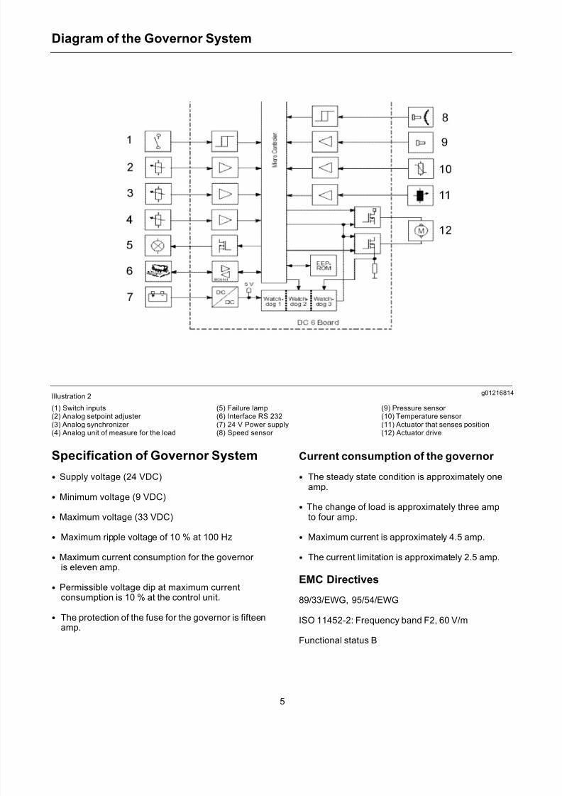
Diagram of the Governor System
g01216814Illustration 2
(1) Switch inputs
(2) Analog setpoint adjuster (3) Analog synchronizer (4) Analog unit of measure for the load
(5) Failure lamp
(6) Interface RS 232(7) 24 V Power supply(8) Speed sensor
(9) Pressure sensor
(10) Temperature sensor (11) Actuator that senses position(12) Actuator drive
Specification of Governor System
• Supply voltage (24 VDC)
• Minimum voltage (9 VDC)
• Maximum voltage (33 VDC)
• Maximum ripple voltage of 10 % at 100 Hz
• Maximum current consumption for the governor is eleven amp.
• Permissible voltage dip at maximum currentconsumption is 10 % at the control unit.
• The protection of the fuse for the governor is fifteenamp.
Current consumption of the governor
• The steady state condition is approximately oneamp.
• The change of load is approximately three ampto four amp.
• Maximum current is approximately 4.5 amp.
• The current limitation is approximately 2.5 amp.
EMC Directives
89/33/EWG, 95/54/EWG
ISO 11452-2: Frequency band F2, 60 V/m
Functional status B
5
7/26/2019 Pandaros Digital Governor _ Special Instruction _ REHS2806 _ May 2006 _ PERKINS.pdf
http://slidepdf.com/reader/full/pandaros-digital-governor-special-instruction-rehs2806-may-2006-perkinspdf 6/48
ISO 7637-2: Frequency band F2, 60 V/m
Functional status B
ISO 7637-3: Frequency band F2, 60 V/m
Functional status B
VDE 0879-3: Severity Level 4
CE: EN 50081-2, EN 50082-2
All inputs and outputs are protected against a reversevoltage and a short circuit to the battery.
Analog inputs may be set to 0 to 5 volts, 4 to 20 mAor +/- 3 volts in the software.
Digital input engine stop U0 < 2 V, U1 > 6.0 V
Digital output to the failure lamp is Isink < 0.3 A.
Setting for the Feedback
The governor will operate correctly when the controlbox identifies the parameters for the feedback. Theparameters will correspond to 0% and 100% of theposition for the actuator. Whenever an actuator has been replaced, it is necessary to carry out aprocedure to calibrate the feedback.
The DC Desk service tool software can automaticallycarry out a calibration procedure to establish theseparameters.
Note: To properly perform automatic calibration, theactuator must operate smoothly and the actuator
must be able to easily move from 0% to 100% (leftstop and right stop). It is therefore necessary for theactuator to be disconnected from the engine linkage.This procedure is not necessary with the combinedactuator and the valve for the throttle that is installedto gas engines.
6
7/26/2019 Pandaros Digital Governor _ Special Instruction _ REHS2806 _ May 2006 _ PERKINS.pdf
http://slidepdf.com/reader/full/pandaros-digital-governor-special-instruction-rehs2806-may-2006-perkinspdf 7/48
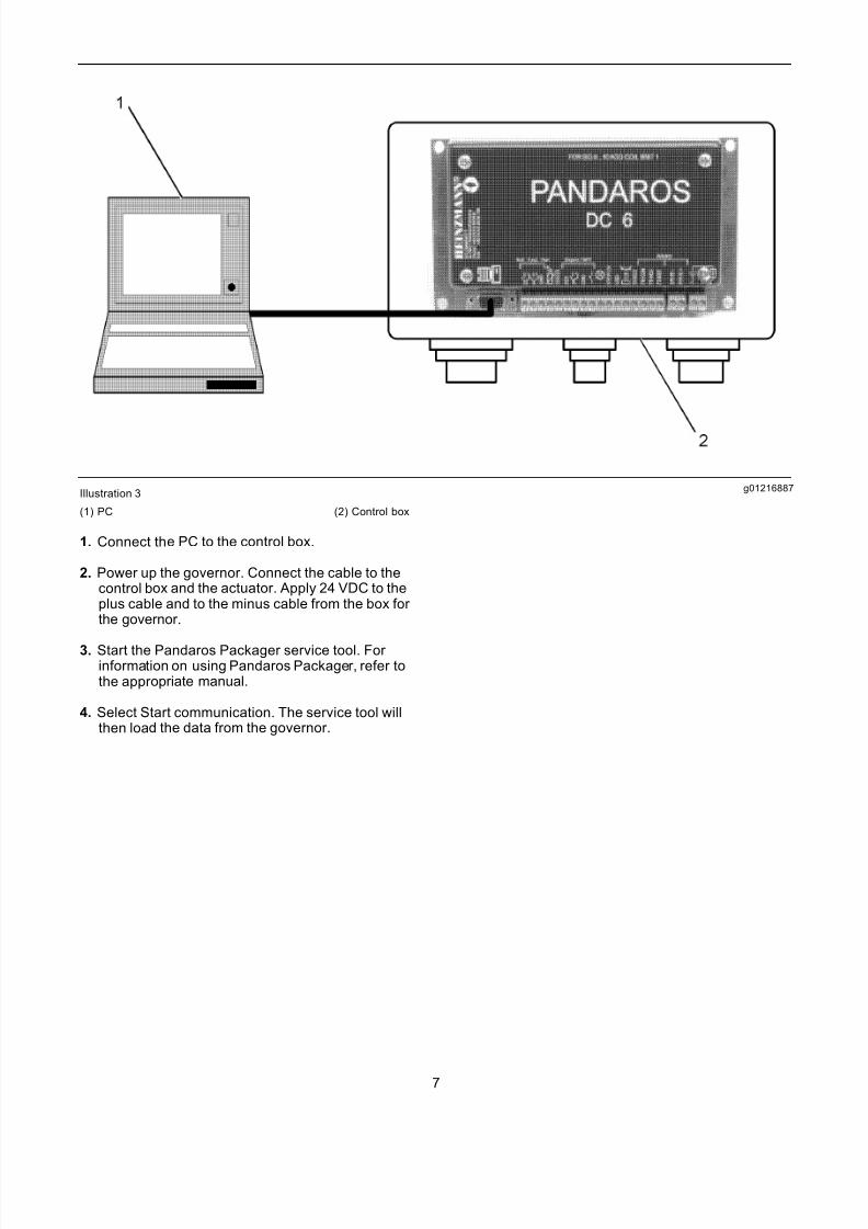
g01216887Illustration 3
(1) PC (2) Control box
1. Connect the PC to the control box.
2. Power up the governor. Connect the cable to thecontrol box and the actuator. Apply 24 VDC to theplus cable and to the minus cable from the box for the governor.
3. Start the Pandaros Packager service tool. For information on using Pandaros Packager, refer tothe appr opriate manual.
4. Select Start communication. The service tool willthen load the data from the governor.
7
7/26/2019 Pandaros Digital Governor _ Special Instruction _ REHS2806 _ May 2006 _ PERKINS.pdf
http://slidepdf.com/reader/full/pandaros-digital-governor-special-instruction-rehs2806-may-2006-perkinspdf 8/48
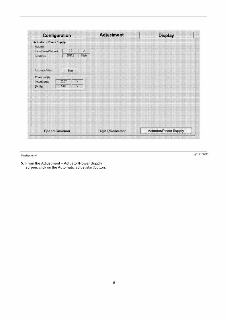
g01216892Illustration 4
5. From the Adjustment – Actuator/Power Supply
screen, click on the Automatic adjust start button.
8
7/26/2019 Pandaros Digital Governor _ Special Instruction _ REHS2806 _ May 2006 _ PERKINS.pdf
http://slidepdf.com/reader/full/pandaros-digital-governor-special-instruction-rehs2806-may-2006-perkinspdf 9/48
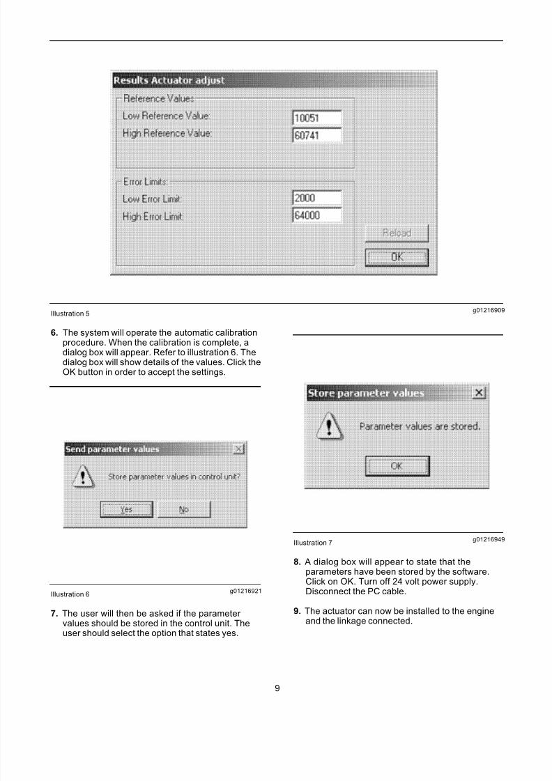
g01216909Illustration 5
6. The system will operate the automatic calibrationprocedure. When the calibration is complete, adialog box will appear. Refer to illustration 6. Thedialog box will show details of the values. Click theOK button in order to accept the settings.
g01216921Illustration 6
7. The user will then be asked if the parameter values should be stored in the control unit. Theuser should select the option that states yes.
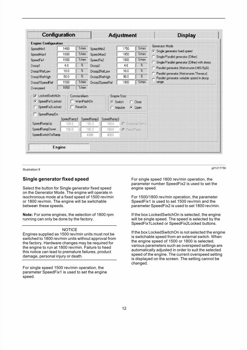
g01216949Illustration 7
8. A dialog box will appear to state that theparameters have been stored by the software.Click on OK. Turn off 24 volt power supply.Disconnect the PC cable.
9. The actuator can now be installed to the engineand the linkage connected.
9

7/26/2019 Pandaros Digital Governor _ Special Instruction _ REHS2806 _ May 2006 _ PERKINS.pdf
http://slidepdf.com/reader/full/pandaros-digital-governor-special-instruction-rehs2806-may-2006-perkinspdf 10/48
Setting the Feedback without theService Tool
When the actuator is replaced and the Service Toolis not available, the setting for the feedback can becalibrated. Follow steps 1 to 6.
g01216965Illustration 8
1. Remove the lid of the IP55 box for the governor.Remove the lid of the Pandaros box.
Note: The later version of the box have a small holein the lid of the box which allows the push button tobe operated without removing the lid.
2. Connect the cable from the control box to theactuator and apply 24 volts to the governor.
3. Locate the push button (1) for the setting for thefeedback. Refer to illustration 8.
4. Ensure that the actuator output shaft has beendisconnected from the engine linkage. Theactuator should be free to move from 0% to 100%.
5. Press the button (1). The system will automaticallycalibrate the feedback.
6. Remove the 24 V supply. Replace the covers andinstall the actuator to the engine.
Configuration
The engine will be configured in accordance with therequirements of the customer. The requirements of the customer are determined from the Sales Order
Process. The configurations that are set in the factoryare shown below:
Speed
• 1500 rev/min
• 1800 rev/min
• 1500/1800 rev/min
10
7/26/2019 Pandaros Digital Governor _ Special Instruction _ REHS2806 _ May 2006 _ PERKINS.pdf
http://slidepdf.com/reader/full/pandaros-digital-governor-special-instruction-rehs2806-may-2006-perkinspdf 11/48
Droop/Isochronous
The default configuration will be isochronousoperation. If the engine has been required to run indroop, the desired percentage droop will also havebeen set.
External Input for Speed Control
Single generator fixed speed
The default configuration is for an engine in order tooperate in single generator mode. Single generator mode means that the mode is not paralleled withany other generator. This mode has no provision for external speed control. The speed will be fixed at1500 rev/min or 1800 rev/min.
Single generatorvariable speed
This mode allows the Load Sharer input to be usedwith an external 5K potentiometer for manual speedsetting control. In this configuration, an external
speed setting control must be connected in order toenable the engine to run. There are options for either the synchronizer or the droop operation.
Parallel generator HeinzmannLSU/Sync
The Heinzmann LSU/Sync provides the connectionto the standard Heinzmann sharing of the analogloads and the synchronizing units. The connectionsare designated A3, B3 and E3.
• A3 is the common connection.
• B3 is the input for the synchronizer.
• E3 is the load sharer input.
In this configuration, the necessary load sharing or synchronizing inputs must be connected in order toallow the engine to run.
Parallel generator LSU/Sync
This configuration will be determined from adiscussion with the provider of the genset. The
configuration is available on special order. Perkinsmust agree with the configuration. The inputs for thespeed/load control are +/- 3 V or 4-20mA.
Note: Any other changes to the configurationrequire the use of the Service Tool and the specialcommunication cable. Refer to the Service Toolmanual f or information on other configurableparameters.
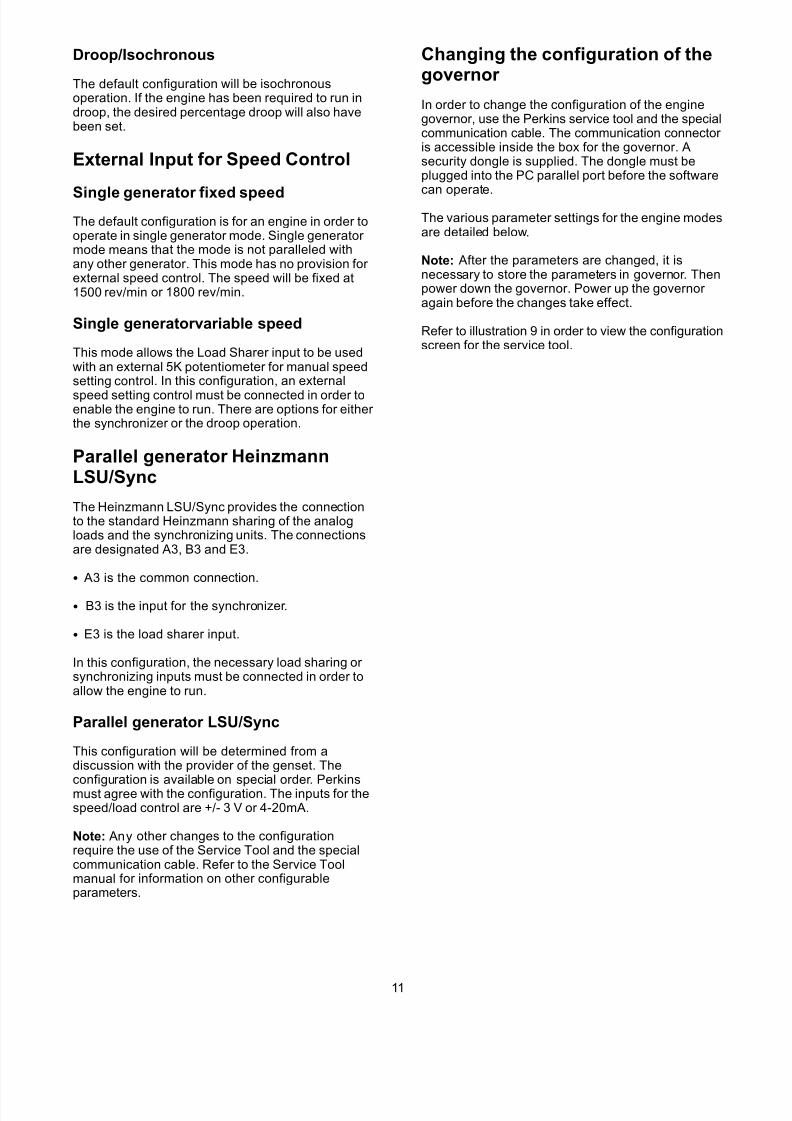
Changing the configuration of thegovernor
In order to change the configuration of the enginegovernor, use the Perkins service tool and the specialcommunication cable. The communication connector is accessible inside the box for the governor. Asecurity dongle is supplied. The dongle must beplugged into the PC parallel port before the software
can operate.
The various parameter settings for the engine modesare detailed below.
Note: After the parameters are changed, it isnecessary to store the parameters in governor. Thenpower down the governor. Power up the governor again before the changes take effect.
Refer to illustration 9 in order to view the configurationscreen for the service tool.
11
7/26/2019 Pandaros Digital Governor _ Special Instruction _ REHS2806 _ May 2006 _ PERKINS.pdf
http://slidepdf.com/reader/full/pandaros-digital-governor-special-instruction-rehs2806-may-2006-perkinspdf 12/48
g01217756Illustration 9
Single generator fixed speed
Select the button for Single generator fixed speedon the Generator Mode. The engine will operate inisochronous mode at a fixed speed of 1500 rev/minor 1800 rev/min. The engine will be switchablebetween these speeds.
Note: For some engines, the selection of 1800 rpmrunning can only be done by the factory.
NOTICEEngines supplied as 1500 rev/min units must not beswitched to 1800 rev/min units without approval fromthe factory. Hardware changes may be required for the engine to run at 1800 rev/min. Failure to heedthis notice can lead to premature failures, productdamage, personal injury or death.
For single speed 1500 rev/min operation, theparameter SpeedFix1 is used to set the enginespeed.
For single speed 1800 rev/min operation, the
parameter number SpeedFix2 is used to set theengine speed.
For 1500/1800 rev/min operation, the parameter SpeedFix1 is used to set 1500 rev/min and theparameter SpeedFix2 is used to set 1800 rev/min.
If the box LockedSwitchOn is selected, the enginewill be single speed. The speed is selected by theSpeedFix1Locked or SpeedFix2Locked buttons.
If the box LockedSwitchOn is not selected the engineis switchable speed from an external switch. Whenthe engine speed of 1500 or 1800 is selected,
various parameters such as overspeed settings areautomatically adjusted in order to suit the selectedspeed of the engine. The current overspeed settingis displayed on the screen. The setting cannot bechanged.
12
7/26/2019 Pandaros Digital Governor _ Special Instruction _ REHS2806 _ May 2006 _ PERKINS.pdf
http://slidepdf.com/reader/full/pandaros-digital-governor-special-instruction-rehs2806-may-2006-perkinspdf 13/48
Single generator variable speed
Droop
For manual parallel operation, droop mode is requiredwith an engine speed that is capable of being variedfor synchronizing and the sharing of the load. Thismode is selected by setting the Generator Mode toParallel generator variable speed with droop.
When the engine operates in droop mode, thefollowing parameters must be set:
Droop
Set the required percentage droop. There areseparate droop adjustments for 1500 rev/min and1800 rev/min engines. The 1800 rev/min settings arelabelled Droop2.
DroopRefLo
To set the parameter, turn the governor to the ONposition. Run the engine at no load. Read theparameter ActPos from the Speed Governor –
Adjustment tab. Refer to illustration 10. Enter thevalue into the parameter DroopRefLo.
DroopRefHi
To set the parameter, the governor must be poweredup with the engine at full load. Read the parameter
ActPos and enter the value into the parameter DroopRefHi.
Setting DroopRefLo and DroopRefHi in this wayensures that the percentage droop set is accurate.
DroopSpeedRef
Set this parameter to the nominal running speed of the engine (1500 or 1800 rev/min).
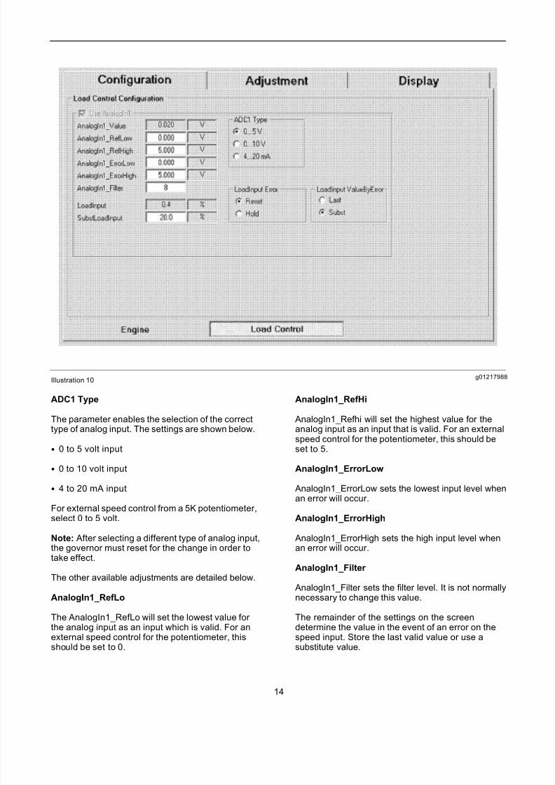
The analog input which will be used for the externalspeed control must now be set up. To set up theanalog input, select the Configuration – Load Controltab. A screen will be displayed. Refer to illustration10.
13
7/26/2019 Pandaros Digital Governor _ Special Instruction _ REHS2806 _ May 2006 _ PERKINS.pdf
http://slidepdf.com/reader/full/pandaros-digital-governor-special-instruction-rehs2806-may-2006-perkinspdf 14/48
g01217988Illustration 10
ADC1 Type
The parameter enables the selection of the correcttype of analog input. The settings are shown below.
• 0 to 5 volt input
• 0 to 10 volt input
• 4 to 20 mA input
For external speed control from a 5K potentiometer,select 0 to 5 volt.
Note: After selecting a different type of analog input,
the governor must reset for the change in order totake effect.
The other available adjustments are detailed below.
AnalogIn1_RefLo
The AnalogIn1_RefLo will set the lowest value for the analog input as an input which is valid. For anexternal speed control for the potentiometer, thisshould be set to 0.
AnalogIn1_RefHi
AnalogIn1_Refhi will set the highest value for theanalog input as an input that is valid. For an externalspeed control for the potentiometer, this should beset to 5.
AnalogIn1_ErrorLow
AnalogIn1_ErrorLow sets the lowest input level whenan error will occur.
AnalogIn1_ErrorHigh
AnalogIn1_ErrorHigh sets the high input level when
an error will occur.
AnalogIn1_Filter
AnalogIn1_Filter sets the filter level. It is not normallynecessary to change this value.
The remainder of the settings on the screendetermine the value in the event of an error on thespeed input. Store the last valid value or use asubstitute value.
14
7/26/2019 Pandaros Digital Governor _ Special Instruction _ REHS2806 _ May 2006 _ PERKINS.pdf
http://slidepdf.com/reader/full/pandaros-digital-governor-special-instruction-rehs2806-may-2006-perkinspdf 15/48
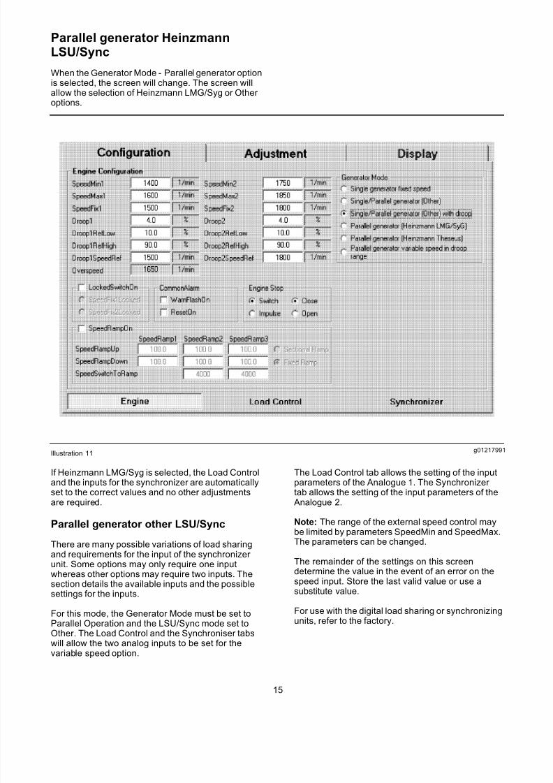
Parallel generator HeinzmannLSU/Sync
When the Generator Mode - Parallel generator optionis selected, the screen will change. The screen willallow the selection of Heinzmann LMG/Syg or Other options.
g01217991Illustration 11
If Heinzmann LMG/Syg is selected, the Load Controland the inputs for the synchronizer are automaticallyset to the correct values and no other adjustmentsare required.
Parallel generator other LSU/Sync
There are many possible variations of load sharingand requirements for the input of the synchronizer unit. Some options may only require one inputwhereas other options may require two inputs. Thesection details the available inputs and the possiblesettings for the inputs.
For this mode, the Generator Mode must be set toParallel Operation and the LSU/Sync mode set toOther. The Load Control and the Synchroniser tabswill allow the two analog inputs to be set for thevariable speed option.
The Load Control tab allows the setting of the inputparameters of the Analogue 1. The Synchronizer tab allows the setting of the input parameters of the
Analogue 2.
Note: The range of the external speed control maybe limited by parameters SpeedMin and SpeedMax.The parameters can be changed.
The remainder of the settings on this screendetermine the value in the event of an error on thespeed input. Store the last valid value or use asubstitute value.
For use with the digital load sharing or synchronizingunits, refer to the factory.
15
7/26/2019 Pandaros Digital Governor _ Special Instruction _ REHS2806 _ May 2006 _ PERKINS.pdf
http://slidepdf.com/reader/full/pandaros-digital-governor-special-instruction-rehs2806-may-2006-perkinspdf 16/48
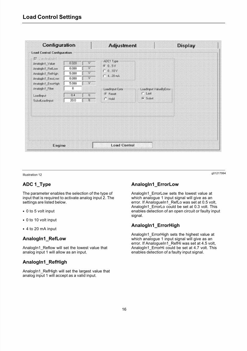
Load Control Settings
g01217994Illustration 12
ADC 1_Type
The parameter enables the selection of the type of input that is required to activate analog input 2. Thesettings are listed below.
• 0 to 5 volt input
• 0 to 10 volt input
• 4 to 20 mA input
AnalogIn1_RefLow
AnalogIn1_Reflow will set the lowest value thatanalog input 1 will allow as an input.
AnalogIn1_RefHigh
AnalogIn1_RefHigh will set the largest value thatanalog input 1 will accept as a valid input.
AnalogIn1_ErrorLow
AnalogIn1_ErrorLow sets the lowest value atwhich analogue 1 input signal will give as anerror. If AnalogueIn1_RefLo was set at 0.5 volt,
AnalogIn1_ErrorLo could be set at 0.3 volt. Thisenables detection of an open circuit or faulty inputsignal.
AnalogIn1_ErrorHigh
AnalogIn1_ErrorHigh sets the highest value atwhich analogue 1 input signal will give as anerror. If AnalogueIn1_RefHi was set at 4.5 volt,
AnalogIn1_ErrorHi could be set at 4.7 volt. Thisenables detection of a faulty input signal.
16
7/26/2019 Pandaros Digital Governor _ Special Instruction _ REHS2806 _ May 2006 _ PERKINS.pdf
http://slidepdf.com/reader/full/pandaros-digital-governor-special-instruction-rehs2806-may-2006-perkinspdf 17/48
LoadControlFactor andLoadControlReference
If analogue input 1 is used, the two parameters setthe range of the external speed control and thereference % for nominal speed. If 1500 rev/min is thenominal running speed and speed variation of +/- 5%speed variation is required, set LoadControlFactor at10% and LoadControlReference at 50%.
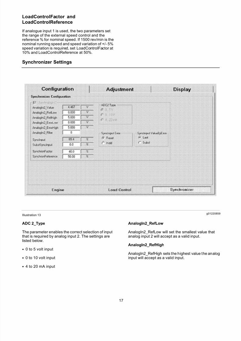
Synchronizer Settings
g01220859Illustration 13
ADC 2_Type
The parameter enables the correct selection of inputthat is required by analog input 2. The settings arelisted below.
• 0 to 5 volt input
• 0 to 10 volt input
• 4 to 20 mA input
AnalogIn2_RefLow
AnalogIn2_RefLow will set the smallest value thatanalog input 2 will accept as a valid input.
AnalogIn2_RefHigh
AnalogIn2_RefHigh sets the highest value the analoginput will accept as a valid input.
17
7/26/2019 Pandaros Digital Governor _ Special Instruction _ REHS2806 _ May 2006 _ PERKINS.pdf
http://slidepdf.com/reader/full/pandaros-digital-governor-special-instruction-rehs2806-may-2006-perkinspdf 18/48
AnalogIn2_ErrorLow
AnalogIn2_Err orLow sets the lowest value atwhich the analog 2 input signal will give anerror. If AnalogueIn2_RefLo was set at 0.5 volt,
AnalogIn2_Err orLo could be set at 0.3 volt. Thisenables detection of an open circuit or faulty inputsignal.
AnalogIn2_ErrorHigh
AnalogIn2_Er rorHigh sets the highest value atwhich the analog 2 input signal will give anerror. If AnalogueIn2_RefHi is set at 4.5 volt,
AnalogIn2_ErrorHi could be set at 4.7 volt. Thisenables detection of a faulty input signal.
SynchronFactor and SynchronReference
When analog input 2 is used, the two parametersset the range of the external speed control. Thetwo parameters will set the reference % for nominalspeed. If 1500 rev/min is the nominal running speedand speed var iation of +/- 5% speed variation
is required, set SynchronFactor at 10% andSynchronReference at 50%.
Additional Programmable Parameters
The section will list other parameters that areavailable. The section will provide an explanation of the functions of the parameter and the calibrationprocedures. These parameters are available on theConfiguration – Engine tab.
Engine Configuration
SpeedMin1 and SpeedMin2
The SpeedMin1 & SpeedMin2 parameter will set theminimum speed for the engine operation.
SpeedMax1 and SpeedMax2
SpeedMax1 and SpeedMax2 sets the maximumspeed for the engine operation.
Engine Stop
Switch or Impulse
When the parameter is set to switch the engine stopis active when the stop command is in operation.When the parameter is set to Impulse, the enginestop is active by a single switching pulse until theengine stops.
Close or Open
If this is set to Open then opening the stop switch willstop the engine. If this is set to Close then closing thestop switch will stop the engine.
Common Alarm
Connect a 24 volt lamp to the output in order toindicate a fault with the governor.
Adjustment of PID parameters
The engine is supplied with the governor PID(Proportional, Integral and Derivative) gainparameters. The PID will give a stable operation withthe majority of engine and alternator combinations.When instability occurs with a particular combinationof engines and alternators, it will be necessary tochange the governor PID.
The PID parameters are available on the Adjustment – Speed Gover nor tab. Refer to illustration 14.
18
7/26/2019 Pandaros Digital Governor _ Special Instruction _ REHS2806 _ May 2006 _ PERKINS.pdf
http://slidepdf.com/reader/full/pandaros-digital-governor-special-instruction-rehs2806-may-2006-perkinspdf 19/48
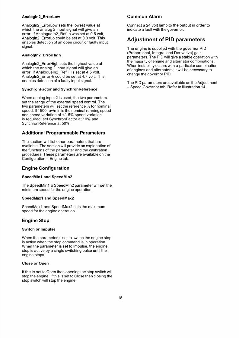
g01220944Illustration 14
To set the parameters, the engine is started. The
engine can be operated to the working point. Theadjustment can be made at this point. Usually, thisworking point will be at rated speed and off-load.To optimize the PID parameters, use the followingprocedure.
• Increase the P-factor Gain until the engine tendsto become unstable. Decrease the P-factor untilthe speed oscillations disappear or the speedoscillations are reduced to a moderate level.
• Increase the I-factor Stability until the engineoperation alters to speed oscillations that havelonger waves.
• Increase the D-factor Derivative until the speedoscillations disappear. If the oscillations cannot beeliminated by the D-factor, the I-factor must bereduced.
Note: The D-factor must not be increased beyond25%. This will cause the actuator to draw excesscurrent.
Set the parameter values. Interrupt the engine speed
for a short period of time by operating the engine stopswitch. Observe the transient response. Continueto modify the PID parameters until the transientresponse is satisfactory.
PID Maps
The PID values which give optimum performanceare different for the various load values. Gains maybe greater with increasing load. The governor gainsare plotted. Plot gain versus load. The maps arecreated during the process of engine development.The service tool can change the maps.
There are two sets of PID maps. One map is for speed. The speed is determined by the parameter SpeedFix1. The other map is for speed that isdetermined by the parameter SpeedFix2.
19
7/26/2019 Pandaros Digital Governor _ Special Instruction _ REHS2806 _ May 2006 _ PERKINS.pdf
http://slidepdf.com/reader/full/pandaros-digital-governor-special-instruction-rehs2806-may-2006-perkinspdf 20/48
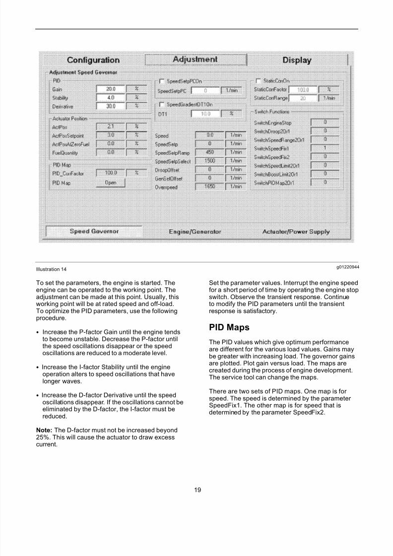
To adjust the maps, on the Adjustment – Speedgovernor screen, click the PID Map open button.Then select the edit button on the map screen. For engines that are a fixed speed, only the first columnis used. If necessary, change the gain entry againstthe actuator position (Y axis) when the instabilityof the gain occurs. The values are percentages.For example, 100 represents 100%. This does notchange the basic PID values.
g01220950Illustration 15
Speed Ramps
Speed ramps are not normally used in generating setapplications. For pump sets it is preferable to havea ramp in speed that is slow from idle speed to fullspeed.
To achieve a slow ramp in speed, the control providesramps that retard the acceleration. The rate of delayof increasing or decreasing the set value can beadjusted separately in either direction. Furthermore,it is possible to decide on the type of speed ramp viathe parameter.
• FixedRamp is Fixed speed ramp.
• Sectional Ramp is Sectional speed ramp.
20
7/26/2019 Pandaros Digital Governor _ Special Instruction _ REHS2806 _ May 2006 _ PERKINS.pdf
http://slidepdf.com/reader/full/pandaros-digital-governor-special-instruction-rehs2806-may-2006-perkinspdf 21/48
The ramp functions are activated by selecting theSpeedRampOn box on the Configuration – Enginetab.
Fixed Speed Ramp
To use the fixed speed ramp, select the Fixed Rampbutton. The fixed speed ramp is the rate of delay for the setpoint. The fixed speed ramp is identical acrossthe entire speed range. The ramp rates for rampingupward and downward can be separately set via theparameters under SpeedRamp1.
• SpeedRampUp is the ramp rate for the upwardramp.
• SpeedRampDown is the ramp rate for thedownward ramp.
The unit of these parameters is speed increase resp.speed decrease per second (revolutions per minuteper second = rpmps). When ramping is desired inone direction the maximum value of the parameter is(4000 rpmps). The maximum value of the parameter is entered for the other direction.
The speed setpoint that is delayed by the ramp canbe viewed by the parameter SpeedSetpRamp. Theparameter SpeedSetpSelect represents the speedsetpoint f or the ramp.
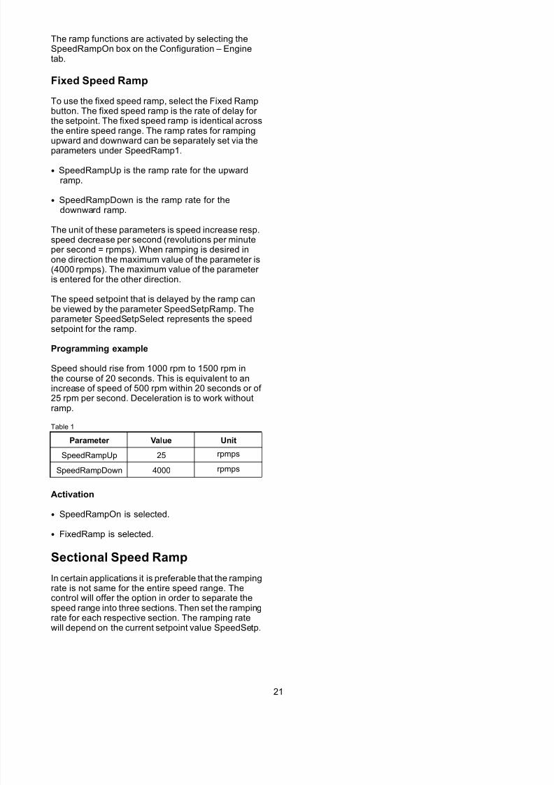
Programming example
Speed should rise from 1000 rpm to 1500 rpm inthe course of 20 seconds. This is equivalent to anincrease of speed of 500 rpm within 20 seconds or of 25 rpm per second. Deceleration is to work without
ramp.Table 1
Parameter Value Unit
SpeedRampUp 25 rpmps
SpeedRampDown 4000 rpmps
Activation
• SpeedRampOn is selected.
• FixedRamp is selected.
Sectional Speed Ramp
In certain applications it is preferable that the rampingrate is not same for the entire speed range. Thecontrol will offer the option in order to separate thespeed range into three sections. Then set the rampingrate for each respective section. The ramping ratewill depend on the current setpoint value SpeedSetp.
21
7/26/2019 Pandaros Digital Governor _ Special Instruction _ REHS2806 _ May 2006 _ PERKINS.pdf
http://slidepdf.com/reader/full/pandaros-digital-governor-special-instruction-rehs2806-may-2006-perkinspdf 22/48
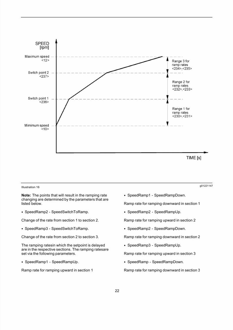
g01221147Illustration 16
Note: The points that will result in the ramping ratechanging are determined by the parameters that arelisted below.
• SpeedRamp2 - SpeedSwitchToRamp.
Change of the rate from section 1 to section 2.
• SpeedRamp3 - SpeedSwitchToRamp.
Change of the rate from section 2 to section 3.
The ramping ratesin which the setpoint is delayedare in the respective sections. The ramping ratesareset via the following parameters.
• SpeedRamp1 - SpeedRampUp.
Ramp rate for ramping upward in section 1
• SpeedRamp1 - SpeedRampDown.
Ramp rate for ramping downward in section 1
• SpeedRamp2 - SpeedRampUp.
Ramp rate for ramping upward in section 2
• SpeedRamp2 - SpeedRampDown.
Ramp rate for ramping downward in section 2
• SpeedRamp3 - SpeedRampUp.
Ramp rate for ramping upward in section 3
• SpeedRamp - SpeedRampDown.
Ramp rate for ramping downward in section 3
22
7/26/2019 Pandaros Digital Governor _ Special Instruction _ REHS2806 _ May 2006 _ PERKINS.pdf
http://slidepdf.com/reader/full/pandaros-digital-governor-special-instruction-rehs2806-may-2006-perkinspdf 23/48
The unit of the parameters is given by an increasein speed or a decrease of speed per second. Theramps are enabled by selecting the SpeedRampOnbox. Selection of the sectional speed ramp is madeby selecting the Sectional Ramp button.
Two ramp sections can be provided. The switch point2 is represented by the parameter SpeedRamp3.Switch point 2 must be set to the maximum valueof speed.
The speed setpoint is delayed by the ramp. Thespeed setpoint can be viewed by the parameter SpeedSetpRamp. The parameter SpeedSetpSelectrepresents the speed setpoint that the ramp issupposed to arrive at.
Programming Example
The upward ramping rate between the minimumspeed and 800 rpm is 100 rpmps. The reductionof speed is operated in a short period of time. Thespeed range of upward ramping rate lies between800 rpm and 1200 rpm is 50 rpmps. The downwardramping rate is 40 rpmps. Between 1200 rpm and themaximum speed the upward rates and the downwardrates are 20 rpmps.
Table 2
Parameter Value Unit
SpeedRamp1 - SpeedRampUp 100 rpmps
SpeedRamp1 - SpeedRampDown 4000 rpmps
SpeedRamp2 - SpeedRampUp 50 rpmps
SpeedRamp2 - SpeedRampDown 40 rpmps
SpeedRamp3 - SpeedRampUp 20 rpmps
SpeedRamp3 - SpeedRampDown 20 rpmps
SpeedRamp2 - SpeedSwitchToRamp 800 rpmps
SpeedRamp3 - SpeedSwitchToRamp 1200 rpmps
Activation
• SpeedRampOn is selected.
• Sectional Ramp is selected.
System Wiring
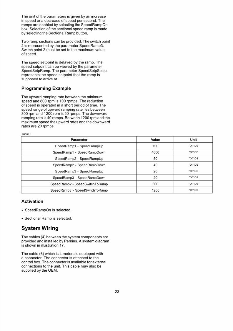
The cables (4) between the system components areprovided and installed by Perkins. A system diagramis shown in illustration 17.
The cable (6) which is 4 meters is equipped witha connector. The connector is attached to thecontrol box. The connector is available for externalconnections to the unit. This cable may also besupplied by the OEM.
23
7/26/2019 Pandaros Digital Governor _ Special Instruction _ REHS2806 _ May 2006 _ PERKINS.pdf
http://slidepdf.com/reader/full/pandaros-digital-governor-special-instruction-rehs2806-may-2006-perkinspdf 24/48
g01237886Illustration 17
Typical example
(1) Control Box(2) Boost Pressure Sensor (if equipped)
(3) Actuator (5) Magnetic Pickup
24

7/26/2019 Pandaros Digital Governor _ Special Instruction _ REHS2806 _ May 2006 _ PERKINS.pdf
http://slidepdf.com/reader/full/pandaros-digital-governor-special-instruction-rehs2806-may-2006-perkinspdf 25/48
External Connections Perkins SuppliedCable for Diesel Engines
g01237943
Illustration 18
• B+
A positive 24 VDC supply to the governor from thebattery
A 15A fuse or a circuit breaker must be installed inthe circuit for overcurrent or short circuit protection.
Note: When an overspeed fault occurs the supplyfrom the battery to the actuator and the stop solenoidshould be removed.
• B-
A negative 24 VDC is supplied from the battery tothe governor.
• Run/Stop Switch
The switch that is connected from the wire to + 24Vwill enable the engine to run if the switch is closed.The engine will stop when the switch is open. This isthe preferred method of normal stop. If the method of normal stop is not required, connect the wire for theRun/Stop Switch to +24V.
• A3
A3 is common for synchronizer/load sharer input.
• B3
B3 is a input for the synchronizer. B3 may beused for a control signal for speed from an analogsynchronizer. B3 can be used for other externalspeed control that can depend on the configuration.For engines that are fixed speed, no connection isrequired.
• E3
Load sharer input is for a connection to a Heinzmannanalog load sharing unit. For engines of a fixedspeed, no connection is required.
• 0V and 5V
There is a 5V supply for an external speed settingpotentiometer for the configuration of a generator with a single variable speed. For engines with a fixedspeed, no connection is required.
• 1500/1800
The switch that is connected from the wire to +24Vwill enable the engine to be switched between 1500Rev/Min and 1800 Rev/Min speeds when switchable1500/1800 Rev/Min running is configured. For
engines that have a single speed, no connection isrequired. The switchable engine speed of 1500/1800rev/min will return to a engine speed of 1500 rev/min.The switch will occur when there is no electricalconnection.
• Alarm
25

7/26/2019 Pandaros Digital Governor _ Special Instruction _ REHS2806 _ May 2006 _ PERKINS.pdf
http://slidepdf.com/reader/full/pandaros-digital-governor-special-instruction-rehs2806-may-2006-perkinspdf 26/48
The alarm is a digital output in order to indicate a faulton the governor system. Connect a lamp or a relaybetween this connection and +24V for an indication of the fault condition. It is necessary to use the servicetool to establish the reason for the fault indication.
• SCR
SCR is the screen of the cable which is connected tothe metal work of the connector at the control box for
EMC requirements.
• CAN+ and CAN-
CAN bus connections for digital loadsharing/synchronizing (if equipped)
External Connections and the Connector for the Control Box for Diesel Engines
g01237963Illustration 19
26
7/26/2019 Pandaros Digital Governor _ Special Instruction _ REHS2806 _ May 2006 _ PERKINS.pdf
http://slidepdf.com/reader/full/pandaros-digital-governor-special-instruction-rehs2806-may-2006-perkinspdf 27/48
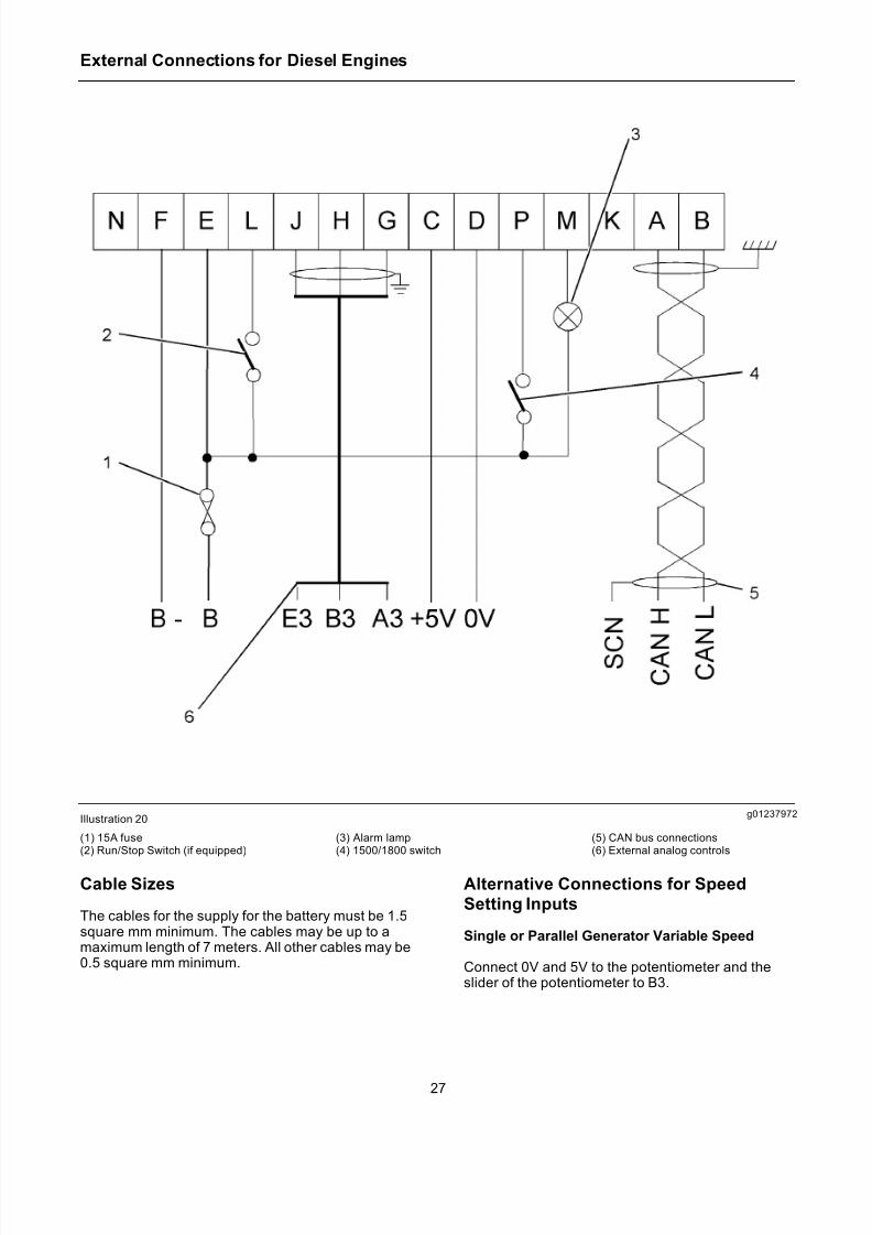
External Connections for Diesel Engines
g01237972Illustration 20
(1) 15A fuse(2) Run/Stop Switch (if equipped)
(3) Alarm lamp(4) 1500/1800 switch
(5) CAN bus connections(6) External analog controls
Cable Sizes
The cables for the supply for the battery must be 1.5square mm minimum. The cables may be up to amaximum length of 7 meters. All other cables may be0.5 square mm minimum.
Alternative Connections for Speed
Setting Inputs
Single or Parallel Generator Variable Speed
Connect 0V and 5V to the potentiometer and theslider of the potentiometer to B3.
27
7/26/2019 Pandaros Digital Governor _ Special Instruction _ REHS2806 _ May 2006 _ PERKINS.pdf
http://slidepdf.com/reader/full/pandaros-digital-governor-special-instruction-rehs2806-may-2006-perkinspdf 28/48
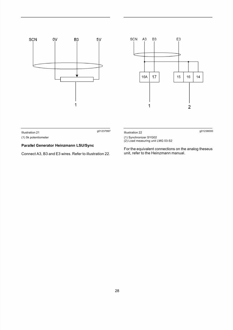
g01237997Illustration 21
(1) 5k potentiometer
Parallel Generator Heinzmann LSU/Sync
Connect A3, B3 and E3 wires. Refer to illustration 22.
g01238000Illustration 22
(1) Synchronizer SYG02(2) Load measuring unit LMG 03-S2
For the equivalent connections on the analog theseusunit, refer to the Heinzmann manual.
28
7/26/2019 Pandaros Digital Governor _ Special Instruction _ REHS2806 _ May 2006 _ PERKINS.pdf
http://slidepdf.com/reader/full/pandaros-digital-governor-special-instruction-rehs2806-may-2006-perkinspdf 29/48
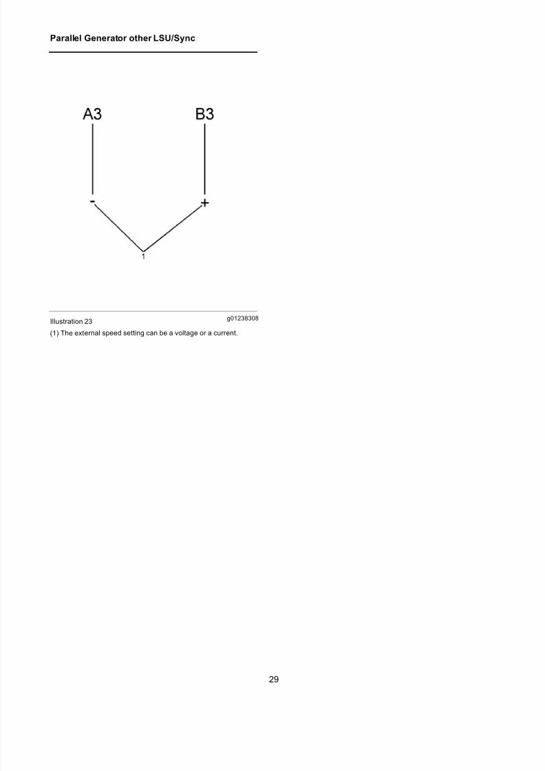
Parallel Generator other LSU/Sync
g01238308Illustration 23
(1) The external speed setting can be a voltage or a current.
29
7/26/2019 Pandaros Digital Governor _ Special Instruction _ REHS2806 _ May 2006 _ PERKINS.pdf
http://slidepdf.com/reader/full/pandaros-digital-governor-special-instruction-rehs2806-may-2006-perkinspdf 30/48
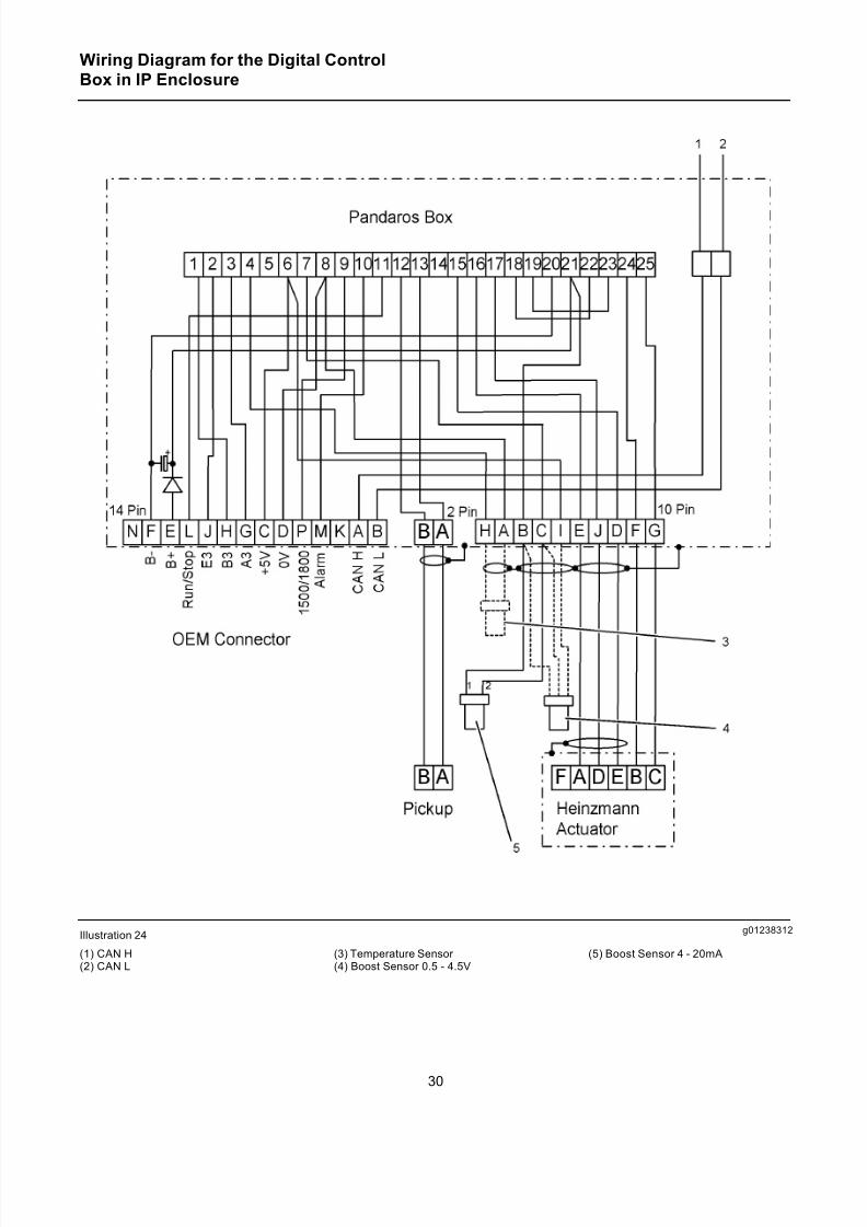
Wiring Diagram for the Digital ControlBox in IP Enclosure
g01238312Illustration 24
(1) CAN H(2) CAN L
(3) Temperature Sensor (4) Boost Sensor 0.5 - 4.5V
(5) Boost Sensor 4 - 20mA
30
7/26/2019 Pandaros Digital Governor _ Special Instruction _ REHS2806 _ May 2006 _ PERKINS.pdf
http://slidepdf.com/reader/full/pandaros-digital-governor-special-instruction-rehs2806-may-2006-perkinspdf 31/48
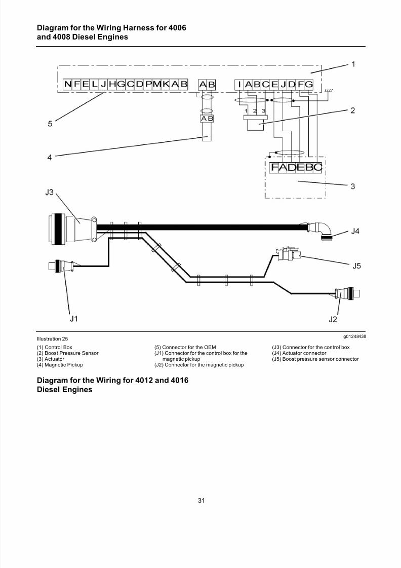
Diagram for the Wiring Harness for 4006and 4008 Diesel Engines
g01248438Illustration 25
(1) Control Box(2) Boost Pressure Sensor (3) Actuator (4) Magnetic Pickup
(5) Connector for the OEM(J1) Connector for the control box for the
magnetic pickup(J2) Connector for the magnetic pickup
(J3) Connector for the control box(J4) Actuator connector (J5) Boost pressure sensor connector
Diagram for the Wiring for 4012 and 4016
Diesel Engines
31
7/26/2019 Pandaros Digital Governor _ Special Instruction _ REHS2806 _ May 2006 _ PERKINS.pdf
http://slidepdf.com/reader/full/pandaros-digital-governor-special-instruction-rehs2806-may-2006-perkinspdf 32/48
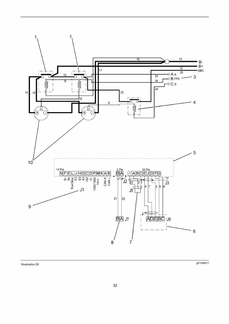
g01248511Illustration 26
32

7/26/2019 Pandaros Digital Governor _ Special Instruction _ REHS2806 _ May 2006 _ PERKINS.pdf
http://slidepdf.com/reader/full/pandaros-digital-governor-special-instruction-rehs2806-may-2006-perkinspdf 33/48
(1) Relay RL2(2) Relay RL1(3) 3 pin Deutsch connector (4) Start relay(5) Control box
(6) Actuator (7) Boost pressure sensor (8) Magnetic pickup(9) Connector for the OEM(10) Stop solenoid
Note: If there is an overspeed fault or an emergencystop, the supply of the battery to the actuator andthe supply of the battery to the FPS input must bestopped.
Diagram for the Wiring for 4006 and 4008Gas Engines
33
7/26/2019 Pandaros Digital Governor _ Special Instruction _ REHS2806 _ May 2006 _ PERKINS.pdf
http://slidepdf.com/reader/full/pandaros-digital-governor-special-instruction-rehs2806-may-2006-perkinspdf 34/48
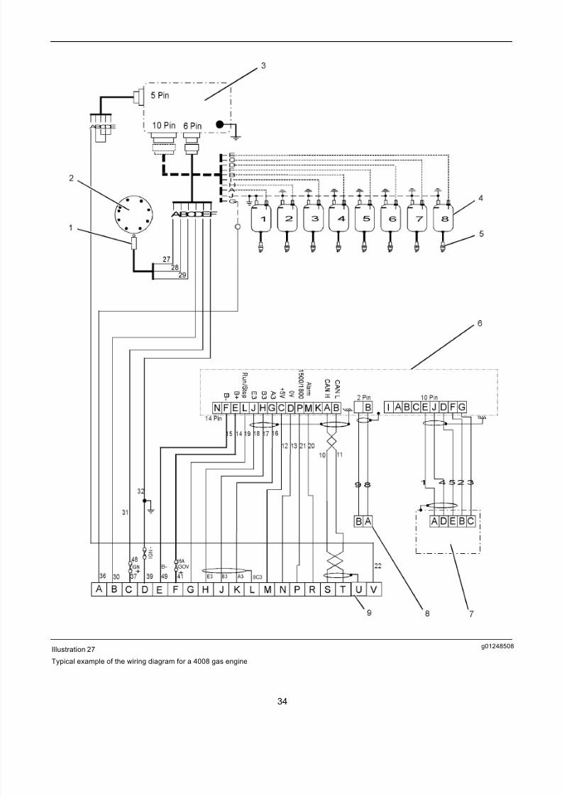
g01248508Illustration 27
Typical example of the wiring diagram for a 4008 gas engine
34
7/26/2019 Pandaros Digital Governor _ Special Instruction _ REHS2806 _ May 2006 _ PERKINS.pdf
http://slidepdf.com/reader/full/pandaros-digital-governor-special-instruction-rehs2806-may-2006-perkinspdf 35/48
(1) Hall effect pickup(2) Magnets on the camshaft gear (3) Ignition unit
(4) Ignition coils(5) HT leads(6) Control box for the governor
(7) Actuator or throttle valve(8) Magnetic speed pickup(9) Connector for the OEM
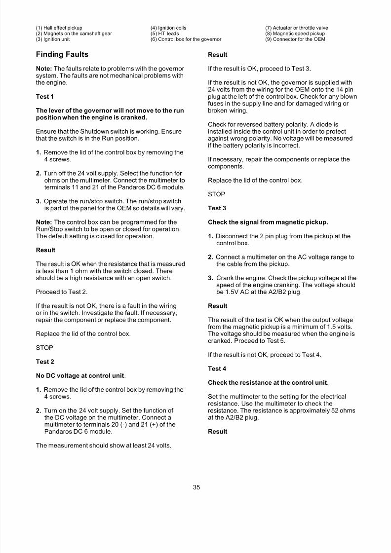
Finding Faults
Note: The faults relate to problems with the governor system. The faults are not mechanical problems withthe engine.
Test 1
The lever of the governor will not move to the runposition when the engine is cranked.
Ensure that the Shutdown switch is working. Ensurethat the switch is in the Run position.
1. Remove the lid of the control box by removing the4 screws.
2. Turn off the 24 volt supply. Select the function for ohms on the multimeter. Connect the multimeter toterminals 11 and 21 of the Pandaros DC 6 module.
3. Operate the r un/stop switch. The run/stop switchis part of the panel for the OEM so details will vary.
Note: The control box can be programmed for theRun/Stop switch to be open or closed for operation.The default setting is closed for operation.
Result
The result is OK when the resistance that is measuredis less than 1 ohm with the switch closed. Thereshould be a high resistance with an open switch.
Proceed to Test 2.
If the result is not OK, there is a fault in the wiringor in the switch. Investigate the fault. If necessary,repair the component or replace the component.
Replace the lid of the control box.
STOP
Test 2
No DC voltage at control unit.
1. Remove the lid of the control box by removing the4 screws.
2. Turn on the 24 volt supply. Set the function of the DC voltage on the multimeter. Connect amultimeter to terminals 20 (-) and 21 (+) of thePandaros DC 6 module.
The measurement should show at least 24 volts.
Result
If the result is OK, proceed to Test 3.
If the result is not OK, the governor is supplied with24 volts from the wiring for the OEM onto the 14 pin
plug at the left of the control box. Check for any blownfuses in the supply line and for damaged wiring or broken wiring.
Check for reversed battery polarity. A diode isinstalled inside the control unit in order to protectagainst wrong polarity. No voltage will be measuredif the battery polarity is incorrect.
If necessary, repair the components or replace thecomponents.
Replace the lid of the control box.
STOP
Test 3
Check the signal from magnetic pickup.
1. Disconnect the 2 pin plug from the pickup at thecontrol box.
2. Connect a multimeter on the AC voltage range tothe cable from the pickup.
3. Crank the engine. Check the pickup voltage at thespeed of the engine cranking. The voltage should
be 1.5V AC at the A2/B2 plug.
Result
The result of the test is OK when the output voltagefrom the magnetic pickup is a minimum of 1.5 volts.The voltage should be measured when the engine iscranked. Proceed to Test 5.
If the result is not OK, proceed to Test 4.
Test 4
Check the resistance at the control unit.
Set the multimeter to the setting for the electricalresistance. Use the multimeter to check theresistance. The resistance is approximately 52 ohmsat the A2/B2 plug.
Result
35
7/26/2019 Pandaros Digital Governor _ Special Instruction _ REHS2806 _ May 2006 _ PERKINS.pdf
http://slidepdf.com/reader/full/pandaros-digital-governor-special-instruction-rehs2806-may-2006-perkinspdf 36/48
If the resistance is OK, it is possible that metalparticles have collected on the magnetic pickup.The reduced output or the gap between the pickupand the teeth of the timing ring may be greater than 0.5 to 0.8 mm. Remove the magnetic pickup.Clean the magnetic pickup or replace the magneticpickup. Refer to Operation and Maintenance Manual,“Engine Speed/Timing Sensor - Clean/Inspect”.
If the result is not OK, there is a wiring fault or the
magnetic pickup is faulty. If necessary, repair themagnetic pickup or replace the magnetic pickup.
STOP
Test 5
An error with the control box exists.
The error lamp will be illuminated.
Remove the 24 Volt supply to the governor. This willclear any errors. Retest the equipment.
Result
If the result is OK, the actuator now moves when theengine is cranking. The error has been cleared.
STOP
If the result is not OK, use Pandaros Packager service tool to investigate the error. Otherwiseproceed to Test 6.
Test 6
Check the actuator..
1. Examine the actuator for objects that block themovement of the actuator. Examine the linkagein order to determine whether the linkage isincorrectly adjusted.
2. Turn off the 24 volts supply. Move the actuator lever by hand in order to check free movement.
3. Remove the connecting plug from the actuator andcheck resistance at terminals B/C. The resistanceshould be approximately 2 ohm.
Result
Without the Pandaros Packager service tool, theabove tests cannot distinguish between the possibilityof a faulty actuator or faulty control box.
If the result is OK, replace the actuator. If necessary,replace the control box. Retest the equipment.
STOP
If the result is not OK, there may be a problemwith the linkage. Correct the fault and retest theequipment. If the resistance of the actuator isincorrect, the actuator is faulty. Replace the actuator and retest the new actuator.
STOP
The governor lever moves when cranking
the engine but the engine will not start(Diesel Engines only)
Test 1
The stop solenoid is not energized (6 and 8cylinder Diesel Engine only).
When the engine is started, take note of the stopsolenoid. The solenoid should be energized. Thesolenoid should be pulled into the correct position.
Result
If the result is OK, there may be a mechanicalproblem. There could be a fault with the fuel system.The faults may prevent the engine starting. Refer tothe manual f or the OEM for further information.
If the result is not OK, proceed to Test 2.
Test 2
Check the voltage at the solenoid.
1. Remove the rubber boot from the stop solenoid inorder to reveal the connections.
2. Select the DC voltage range on the multimeter.Check that there is 24 volts on the positiveterminal of the solenoid and the negative terminalof the solenoid.
Result
If the wiring to the solenoid is OK, the solenoid coilmay have burned out. Replace the solenoid. Takecare to position the replacement solenoid correctly.When the solenoid is energized, the solenoid shouldnot impede the movement of the rack. The solenoidwill push the rack to the stop position when thesolenoid is not energized.
STOP
If the result is not OK, there is a problem in the wiringor circuitry to the solenoid. The circuit is not suppliedby Perkins. Investigate the fault. If necessary, repair the component or replace the component.
STOP
36

7/26/2019 Pandaros Digital Governor _ Special Instruction _ REHS2806 _ May 2006 _ PERKINS.pdf
http://slidepdf.com/reader/full/pandaros-digital-governor-special-instruction-rehs2806-may-2006-perkinspdf 37/48
Test 3
The stop solenoid is not energized (12 and 16cylinder Diesel Engines only).
The solenoids that are installed to the engines havetwo windings. A pull-in winding is supplied with 60amp at 24 volts. The winding is only rated for 30seconds. The second winding is a hold-in winding.The second winding is supplied with around 1 amp.
The second winding is continuously rated. There isa switch that is installed inside the solenoid whichinitially shorts out the hold-in winding. The switch willopen when the switch is pulled in. This will put thepull-in winding and the hold-in winding in series.
The engines are installed with two relays. The stopsolenoids must be energized before the engine cancrank. This operation ensures that the full voltage of the battery is available to move the solenoids into thecorrect position. A situation can occur if the solenoidsare energized at the same time as the starting motor.The voltage drop that is caused due to the startingmotor may result in the incorrect operation of the
solenoids. In this condition, the pull-in winding in thesolenoids will burn out in around 30 seconds. Thecircuitry is shown in illustration 28.
37
7/26/2019 Pandaros Digital Governor _ Special Instruction _ REHS2806 _ May 2006 _ PERKINS.pdf
http://slidepdf.com/reader/full/pandaros-digital-governor-special-instruction-rehs2806-may-2006-perkinspdf 38/48
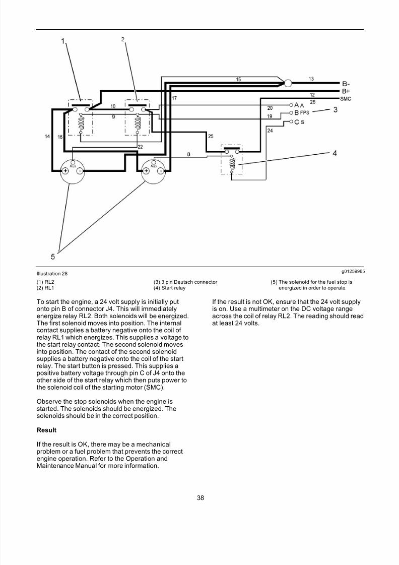
g01259965Illustration 28
(1) RL2(2) RL1
(3) 3 pin Deutsch connector (4) Start relay
(5) The solenoid for the fuel stop isenergized in order to operate.
To start the engine, a 24 volt supply is initially putonto pin B of connector J4. This will immediatelyenergize relay RL2. Both solenoids will be energized.The first solenoid moves into position. The internalcontact supplies a battery negative onto the coil of relay RL1 which energizes. This supplies a voltage tothe start relay contact. The second solenoid movesinto position. The contact of the second solenoidsupplies a battery negative onto the coil of the startrelay. The start button is pressed. This supplies apositive battery voltage through pin C of J4 onto theother side of the start relay which then puts power tothe solenoid coil of the starting motor (SMC).
Observe the stop solenoids when the engine isstarted. The solenoids should be energized. Thesolenoids should be in the correct position.
Result
If the result is OK, there may be a mechanicalproblem or a fuel problem that prevents the correctengine operation. Refer to the Operation andMaintenance Manual for more information.
If the result is not OK, ensure that the 24 volt supplyis on. Use a multimeter on the DC voltage rangeacross the coil of relay RL2. The reading should readat least 24 volts.
38
7/26/2019 Pandaros Digital Governor _ Special Instruction _ REHS2806 _ May 2006 _ PERKINS.pdf
http://slidepdf.com/reader/full/pandaros-digital-governor-special-instruction-rehs2806-may-2006-perkinspdf 39/48
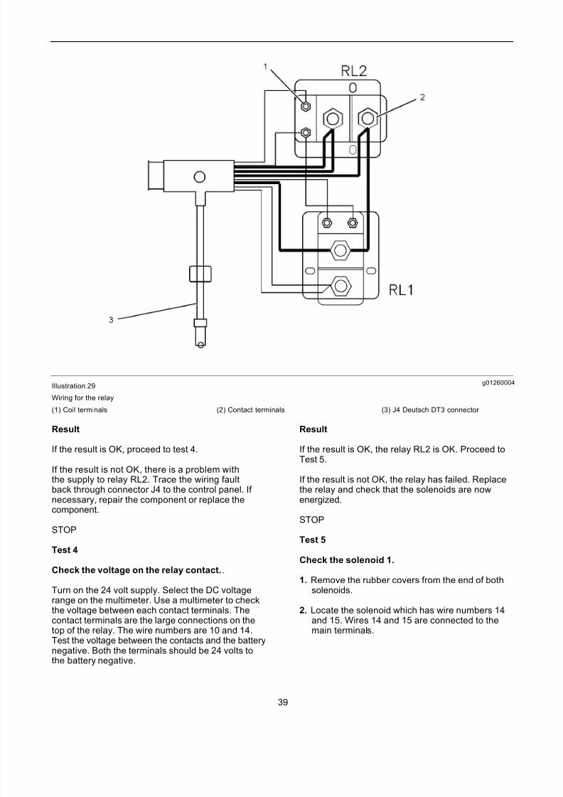
g01260004Illustration 29
Wiring for the relay
(1) Coil terminals (2) Contact terminals (3) J4 Deutsch DT3 connector
Result
If the result is OK, proceed to test 4.
If the result is not OK, there is a problem withthe supply to relay RL2. Trace the wiring faultback through connector J4 to the control panel. If necessary, repair the component or replace thecomponent.
STOP
Test 4
Check the voltage on the relay contact..
Turn on the 24 volt supply. Select the DC voltagerange on the multimeter. Use a multimeter to checkthe voltage between each contact terminals. Thecontact terminals are the large connections on thetop of the relay. The wire numbers are 10 and 14.Test the voltage between the contacts and the batterynegative. Both the terminals should be 24 volts tothe battery negative.
Result
If the result is OK, the relay RL2 is OK. Proceed toTest 5.
If the result is not OK, the relay has failed. Replacethe relay and check that the solenoids are nowenergized.
STOP
Test 5
Check the solenoid 1.
1. Remove the rubber covers from the end of bothsolenoids.
2. Locate the solenoid which has wire numbers 14and 15. Wires 14 and 15 are connected to themain terminals.
39
7/26/2019 Pandaros Digital Governor _ Special Instruction _ REHS2806 _ May 2006 _ PERKINS.pdf
http://slidepdf.com/reader/full/pandaros-digital-governor-special-instruction-rehs2806-may-2006-perkinspdf 40/48
3. Turn on the 24 volt supply. Select the DC voltagerange on the multimeter. Use a multimeter tocheck the voltage on the positive terminal and thenegative terminal of the solenoid. The numbersfor the wires of the terminal are 14 and 15. Thevoltage should read 24 volts.
4. The solenoid should be energized. The solenoidshould be pulled in.
5. Check the voltage between the positive solenoidand Aux terminals. The Aux terminal is markedwith a positive sign within a circle. The voltageshould read 24 volts.
Result
If the result is OK, proceed to test 6.
If the result is not OK, the solenoid is faulty. Replacethe solenoid and retest the solenoid.
STOP
Governor moves to maximum positionwhen power supply is switched on.
Note: Do not attempt to start the engine.
The actuator should not move until the governor receives a signal from the magnetic pickup in order to indicate that the engine is rotating. In this faultcondition, the engine is likely to go into overspeed.
Test 1
Inspect the wiring harness.
1. Carefully examine all wiring between the controlbox and the actuator. Examine the cable to thepickup. Check the continuity of the screen on themagnetic pickup cable since failure of the screencan allow electrical interference to enter the cable.Electrical interference can result in a false speedsignal.
Result
If the result is OK proceed to test 2.
If the result is not OK, repair the wiring harness. If
necessary, replace the wiring harness and retest thewiring harness.
STOP
Test 2
Inspect the control box.
The internal power driver in the control box mayhave failed. Replace the control box and retest theequipment.
STOP
The engine goes to overspeed after
starting
The engine may overspeed due to incorrect as-sembly or adjustment.
Engine overspeed could result in personal injury,loss of life and/or property damage.
Be prepared to stop the engine by activating theengine shutdown system or closing the air inletlines.
Test 1
Check the signal from magnetic pickup.
1. Disconnect the 2 pin plug from the pickup at thecontrol box.
2. Select the AC voltage range on the multimeter.Connect a multimeter to the cable from the pickup.
3. Crank the engine and check pickup voltage atcranking speed. The voltage is approximately1.5V AC at control unit A2/B2 plug.
Result
If the result is OK,the voltage output from the pickupis at least 1.5 volts. The test should be conductedwhen the engine is cranked. Proceed to test 3.
If the result is not OK, proceed to test 2.
Test 2
Check the resistance at the control box.
1. Select the function of the resistance on themultimeter. Use the multimeter to check theresistance at the control unit A2/B2 plug. The
resistance should be approximately 52 ohm.
Result
40

7/26/2019 Pandaros Digital Governor _ Special Instruction _ REHS2806 _ May 2006 _ PERKINS.pdf
http://slidepdf.com/reader/full/pandaros-digital-governor-special-instruction-rehs2806-may-2006-perkinspdf 41/48
If the resistance is OK, it is possible that metalparticles have collected on the magnetic pickup. Thisreduces the output or the gap between the pickupand the teeth for the engine flywheel may be greater than 0.5 to 0.8 mm. Remove the pickup. Clean thepickup or replace the pickup. Reinstall the magneticpickup. Refer to Operation and Maintenance Manual,“Engine Speed/Timing Sensor - Clean/Inspect”.
If the result is not OK, there is a wiring fault or the
magnetic pickup is faulty. If necessary, repair thecomponents or replace the components.
Test 3
Feedback for the actuator is not calibrated to thecontrol box.
1. Disconnect the actuator from the linkage and carryout the Feedback Setting procedure. Reinstall theactuator and retest the actuator.
Result
If the result is OK, STOP.
If the result is not OK, proceed to test 4.
Test 4
Check the parameters of the governor..
1. The test can only be carried out if the PandarosPackager service tool is available. Remove thelid from the control box. Connect the cable thatis supplied with the service tool to the 9 pinconnector on the DC 6 control module.
2. Connect the other end of the cable to the serialport of the PC. Operate the Pandaros Packager.Ensure that the security dongle is connected tothe PC.
3. Check the parameters.
a. The parameters are SpeedFix 1 or 2 on theconfiguration screen. The parameters dependon the 1500/1800 switch position. The defaultis 1500 or 1800 rpm.
b. The default gain on the adjustment screen is12%.
c. The default stability on the adjustment screenis 50%.
d. The default derivative on the adjustment screenis 15%.
4. If the governor gain parameters are much lower than the default values, enter the default values.Retest the equipment.
Result
If the result is OK, the engine no longer goes tooverspeed. If resetting the governor gain parameterscleared the fault, carry out the procedure for thegovernor PID tuning.
STOP
If the result is not OK, proceed to test 5.
Test 5
Replace the governor components.
Result
If the result is OK, STOP.
If the result is not OK, it is likely that there is a jammed linkage or a damaged injector. If necessary,repair the components or replace the components.
STOP
The governor is not stable
Test 1
Check the signal from the magnetic pickup.
1. Disconnect the 2 pin plug from the pickup at thecontrol box.
2. Connect a multimeter on the AC voltage range tothe cable from the pickup.
3. Crank the engine. Check the pickup voltage atthe speed of the crank of the engine at the A2/B2plug. The voltage is approximately 1.5V AC.
Result
If the result is OK, the output from the pickup is atleast 1.5 volts when the engine is cranking. Proceedto test 3.
If the result is not OK, proceed to test 2.
Test 2
Check the resistance at the control unit.
Select the f unction for ohms on the multimeter. Usethe multimeter to check the resistance at the controlunit A2/B2 plug. The resistance is approximately 52ohm.
Result
41
7/26/2019 Pandaros Digital Governor _ Special Instruction _ REHS2806 _ May 2006 _ PERKINS.pdf
http://slidepdf.com/reader/full/pandaros-digital-governor-special-instruction-rehs2806-may-2006-perkinspdf 42/48
If the resistance is OK, it is possible that metalparticles have collected on the magnetic pickup.This has reduced the output or the gap between thepickup and the teeth of the flywheel may be greater than 0.5 to 0.8 mm. Remove the pickup. Clean thepickup or replace the pickup. Reinstall the pickup.Refer to Operation and Maintenance Manual, “EngineSpeed/Timing Sensor - Clean/Inspect”.
If the result is not OK, there is a wiring fault or the
magnetic pickup is faulty. If necessary, repair thepickup or replace the pickup.
Test 3
External speed setting control
1. If no external speed setting control is installed,proceed to test 4.
2. Use the Pandaros Packager service tool.Select Single Generator Fixed Speed on theConfiguration screen.
3. Carry out a reset of the governor by removing andthen reconnecting the 24 volt supply.
4. Run the engine. Run the engine at the loadconditions that cause the engine speed to becomeunstable.
Result
If the result is OK, there is a problem with the externalspeed control and the engine is following variations inthe input voltage. Investigate the fault. If necessary,repair the component or replace the component.
If the result is not OK, return the engine configurationto the previous setting and reset the governor.
Test 4
The governor gains are incorrectly set.
1. By using Pandaros Packager service tool, checkthe parameters.
a. The default gain on the adjustment screen is12%.
b. The default stability on the adjustment screenis 50%.
c. The default derivative on the adjustment screenis 15%.
2. If the governor gain parameters are much lower than the default values, enter the default valuesand retest the equipment.
Result
If the result is OK, STOP.
If the result is not OK, proceed to test 5.
Test 5
Supply voltage.
Connect a multimeter on the DC voltage range to thesupply for the battery to the governor. The reading
with the running of the engine should be a constantand at least 24 volts. The ripple voltage is an ACvoltage that is superimposed onto the 24 volts DCfrom a power supply. An example is a battery charger.The ripple voltage must not exceed 10% of the DCvoltage. An oscilloscope may be required to test theripple voltage.
Result
If the result is OK, proceed to test 6.
If the result is not OK, the input voltage may below. Investigate the wiring and investigate the
power supply circuit. If excessive ripple voltage issuspected, turn off the battery charger. Run theengine. If the problem is corrected, repair the batterycharger or replace the battery charger.
STOP
Test 6
Check the load fluctuations.
If the load is continuously varying, the engine speedgovernor may not be able to keep the speed constant.The condition is not a fault. The condition occurs
in the gensets that are driven by engines. Whenpossible, test the engine with a constant load. Anexample would be banks of loads that are resistant.The test will establish if the load creates the problem.
Result
The engine will run on a steady load. The settingsfor the governor gain are correct. The settings weremeasured in test 4. The load changes are too greatfor the engine capacity. Nothing can be done to theengine in order to improve this condition.
If the result is not OK, proceed to test 7.
Test 7
Play or friction in linkage (Diesel Engines only).
Examine the linkage between the actuator andinjectors for any stiffness or excess play. If necessary,repair the linkage or replace the linkage.
STOP
42
7/26/2019 Pandaros Digital Governor _ Special Instruction _ REHS2806 _ May 2006 _ PERKINS.pdf
http://slidepdf.com/reader/full/pandaros-digital-governor-special-instruction-rehs2806-may-2006-perkinspdf 43/48
Speed droops under load
Test 1
The governor is set up for droop operation..
Use the Pandaros Packager service tool to check themode of the generator on the configuration screen.If the mode that is selected is not within the droopmode, the engine speed will decrease by the droop
percentage as load is increased.
Result
If the result is OK, droop mode is not selected.Proceed to test 2.
If the result is not OK, either select one of thenon-droop operating modes or set the percentagedroop to zero.
STOP
Test 2
The engine is being overloaded..
1. Check if the actuator is at the maximum stop for the fuel. If the actuator is at the maximum stop for the fuel, the engine is being overloaded or there isan engine problem which is preventing the enginefrom producing full power.
2. Use Pandaros Packager service tool to look at thedisplay screen. Inspect the display in order to findout if there are active fuel limits.
Result
If the result is OK, proceed to test 3.
If the result is not OK, investigate the cause of theoverload or the lack of engine power. If the limit of the boost pressure is active, proceed to the symptomthat describes the engine without full load.
STOP
Test 3
The governor stability is incorrectly set.
Carry out the procedure to adjust the PID parameters.
Result
If the result is OK, STOP.
If the result is not OK, proceed to test 4.
Test 4
The control unit is faulty..
Replace the control box. Ensure that the settings inthe new box are correct and retest the engine.
STOP
The engine will not pull load
By using Pandaros Packager service tool, check for an indication of an error with the boost pressure andcheck the boost pressure reading on the Displayscreen with the engine on load.
Result
If the result is OK, the boost pressure sensor isoperating correctly. The term Boost Pressure Limit
Active will display 0 on the display screen. There is amechanical pr oblem with the engine. The engine isprevented from producing a full load. Investigate thefault. If necessary, repair the component.
STOP
If the result is not OK, check the wiring to the boostpressure sensor. If necessary, replace the sensor.
STOP
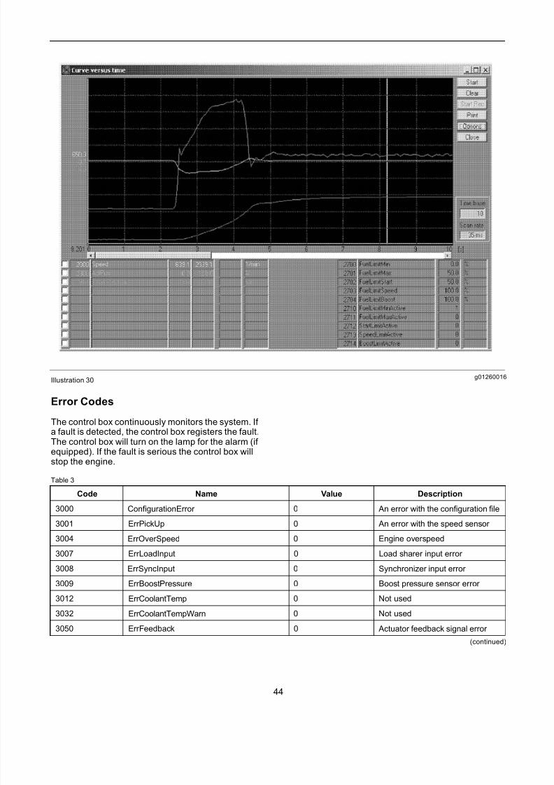
The Service Tool can be used to assist in the findingof faults. The display screens allow parameterssuch as speed, the actuator position and the boostpressure. The display screens and the facility thatproduces gr aphs in real time can be used to get avisual impression of the changes of the parameter during transients. If necessary, the data may bestored to a f ile. This function is available under themain menu Graphic – Curve Versus Time. Refer to
illustration 30.
43
7/26/2019 Pandaros Digital Governor _ Special Instruction _ REHS2806 _ May 2006 _ PERKINS.pdf
http://slidepdf.com/reader/full/pandaros-digital-governor-special-instruction-rehs2806-may-2006-perkinspdf 44/48
g01260016Illustration 30
Error Codes
The control box continuously monitors the system. If a fault is detected, the control box registers the fault.The control box will turn on the lamp for the alarm (if equipped). If the fault is serious the control box willstop the engine.
Table 3
Code Name Value Description
3000 ConfigurationError 0 An error with the configuration file
3001 ErrPickUp 0 An error with the speed sensor
3004 ErrOverSpeed 0 Engine overspeed
3007 ErrLoadInput 0 Load sharer input error
3008 ErrSyncInput 0 Synchronizer input error
3009 ErrBoostPressure 0 Boost pressure sensor error
3012 ErrCoolantTemp 0 Not used
3032 ErrCoolantTempWarn 0 Not used
3050 ErrFeedback 0 Actuator feedback signal error
(continued)
44
7/26/2019 Pandaros Digital Governor _ Special Instruction _ REHS2806 _ May 2006 _ PERKINS.pdf
http://slidepdf.com/reader/full/pandaros-digital-governor-special-instruction-rehs2806-may-2006-perkinspdf 45/48
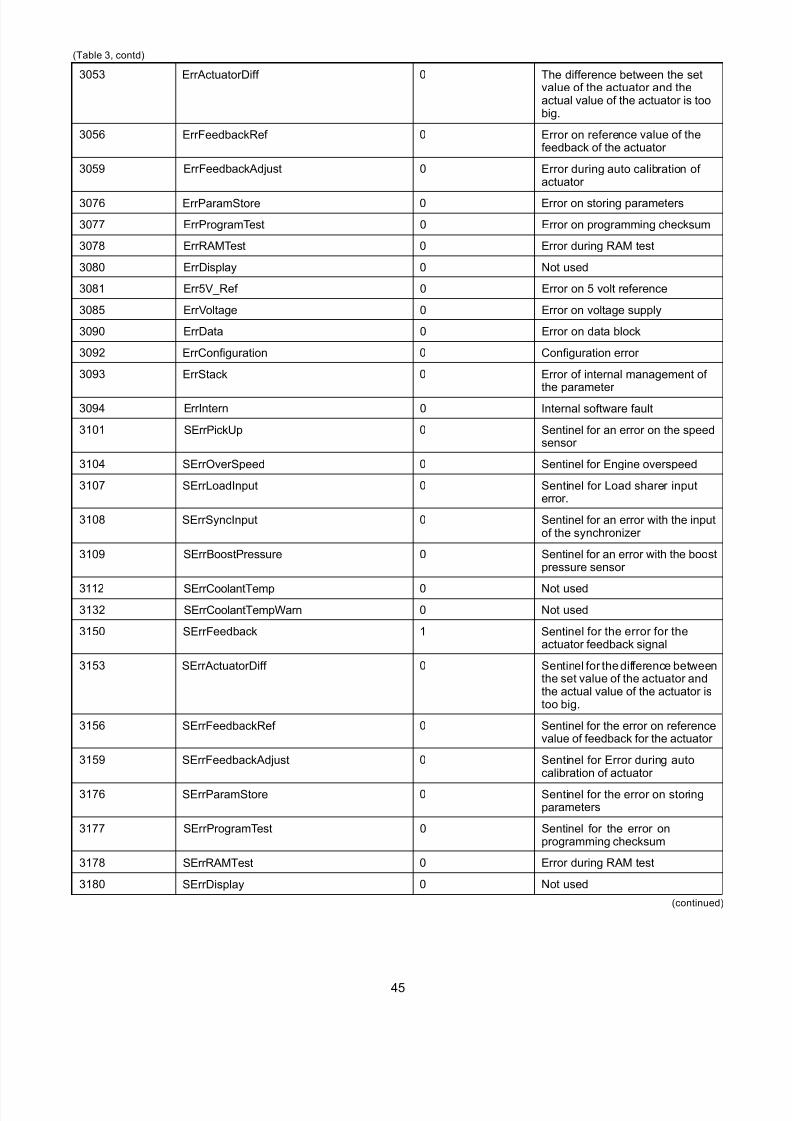
(Table 3, contd)
3053 ErrActuatorDiff 0 The difference between the setvalue of the actuator and theactual value of the actuator is toobig.
3056 ErrFeedbackRef 0 Error on reference value of thefeedback of the actuator
3059 ErrFeedbackAdjust 0 Error during auto calibration of actuator
3076 ErrParamStore 0 Error on storing parameters
3077 ErrProgramTest 0 Error on programming checksum
3078 ErrRAMTest 0 Error during RAM test
3080 ErrDisplay 0 Not used
3081 Err5V_Ref 0 Error on 5 volt reference
3085 ErrVoltage 0 Error on voltage supply
3090 ErrData 0 Error on data block
3092 ErrConfiguration 0 Configuration error
3093 ErrStack 0 Error of internal management of
the parameter 3094 ErrIntern 0 Internal software fault
3101 SErrPickUp 0 Sentinel for an error on the speedsensor
3104 SErrOverSpeed 0 Sentinel for Engine overspeed
3107 SErrLoadInput 0 Sentinel for Load sharer inputerror.
3108 SErrSyncInput 0 Sentinel for an error with the inputof the synchronizer
3109 SErrBoostPressure 0 Sentinel for an error with the boostpressure sensor
3112 SErrCoolantTemp 0 Not used
3132 SErrCoolantTempWarn 0 Not used
3150 SErrFeedback 1 Sentinel for the error for theactuator feedback signal
3153 SErrActuatorDiff 0 Sentinel for the difference betweenthe set value of the actuator andthe actual value of the actuator istoo big.
3156 SErrFeedbackRef 0 Sentinel for the error on referencevalue of feedback for the actuator
3159 SErrFeedbackAdjust 0 Sentinel for Error during autocalibration of actuator
3176 SErrParamStore 0 Sentinel for the error on storingpar ameters
3177 SErrProgramTest 0 Sentinel for the error onprogramming checksum
3178 SErrRAMTest 0 Error during RAM test
3180 SErrDisplay 0 Not used
(continued)
45
7/26/2019 Pandaros Digital Governor _ Special Instruction _ REHS2806 _ May 2006 _ PERKINS.pdf
http://slidepdf.com/reader/full/pandaros-digital-governor-special-instruction-rehs2806-may-2006-perkinspdf 46/48
(Table 3, contd)
3181 SErr5V_Ref 0 Sentinel for the error on 5 voltreference
3185 SErrVoltage 0 Sentinel for the error on voltagesupply
3190 SErrData 0 Sentinel for the error on the datablock
3192 SErrConfiguration 0 Sentinel for the error on the
configuration3193 SErrStack 0 Sentinel for the error of the
management of the internalparameters
3194 SErrIntern 0 Sentinel for the internal softwarefault
3195 SExceptionNumber 0 Sentinel for the exception number
3196 SExceptionAddrLow 0000Hex Sentinel for the software fault
3197 SExceptionAddrHigh 0000Hex Sentinel for the software fault
3198 SExceptionFlag 0000Hex Sentinel for the software fault
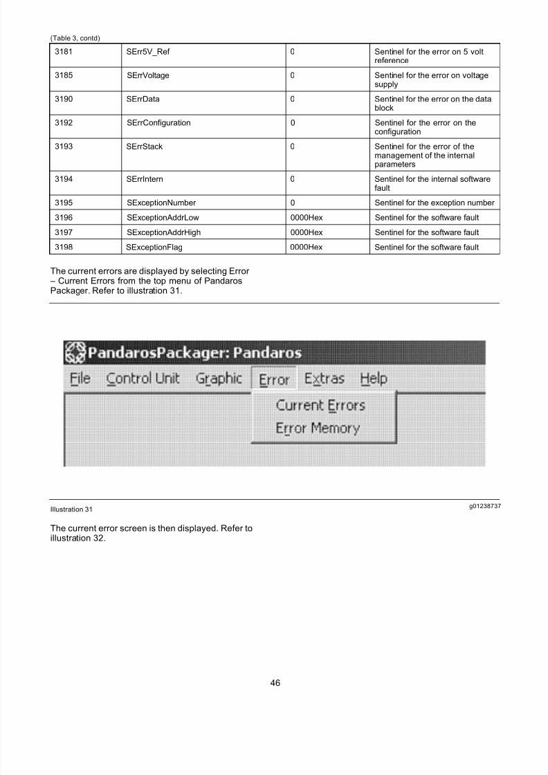
The current errors are displayed by selecting Error – Current Errors from the top menu of PandarosPackager. Refer to illustration 31.
g01238737Illustration 31
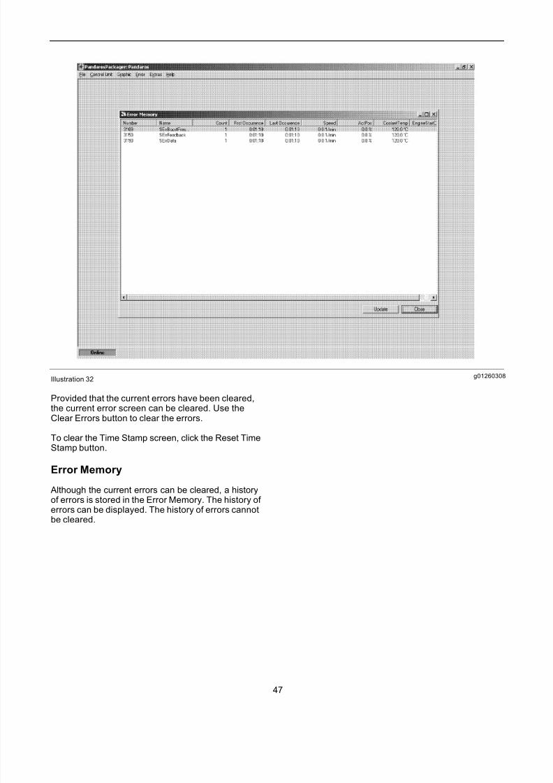
The current error screen is then displayed. Refer toillustration 32.
46
7/26/2019 Pandaros Digital Governor _ Special Instruction _ REHS2806 _ May 2006 _ PERKINS.pdf
http://slidepdf.com/reader/full/pandaros-digital-governor-special-instruction-rehs2806-may-2006-perkinspdf 47/48
g01260308Illustration 32
Provided that the current errors have been cleared,
the current error screen can be cleared. Use theClear Errors button to clear the errors.
To clear the Time Stamp screen, click the Reset TimeStamp button.
Error Memory
Although the current errors can be cleared, a historyof errors is stored in the Error Memory. The history of errors can be displayed. The history of errors cannotbe cleared.
47
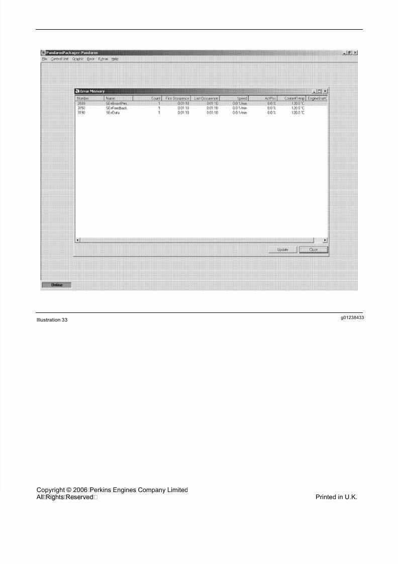
7/26/2019 Pandaros Digital Governor _ Special Instruction _ REHS2806 _ May 2006 _ PERKINS.pdf
http://slidepdf.com/reader/full/pandaros-digital-governor-special-instruction-rehs2806-may-2006-perkinspdf 48/48
g01238433Illustration 33