Panasonic KX - TD816 KX -TD1232 Digital Super Hybrid ... · PDF fileKX-TD816 KX-TD1232 Digital...
160
KX-TD816 KX-TD1232 Digital Super Hybrid System Installation Manual D1232 DIGITAL SUPER HYBRID SYSTEM Panasonic Panasonic D816 DIGITAL SUPER HYBRID SYSTEM Please read this manual before connecting the Digital Super Hybrid System. Panasonic KX-TD1232, KXTD1232, KX TD1232, TD1232, KX-TD816, KXTD816, KX TD816, TD816 www.voicesonic.com Phone: 877-289-2829
Transcript of Panasonic KX - TD816 KX -TD1232 Digital Super Hybrid ... · PDF fileKX-TD816 KX-TD1232 Digital...

KX-TD816KX-TD1232
Digital Super Hybrid System
Installation Manual
D1232DIGITAL SUPER HYBRID SYSTEM
PanasonicPanasonic
D816DIGITAL SUPER HYBRID SYSTEM
Please read this manual before connecting the Digital Super Hybrid System.
Panasonic KX-TD1232, KXTD1232, KX TD1232, TD1232, KX-TD816, KXTD816, KX TD816, TD816
www.voicesonic.comPhone: 877-289-2829
Panasonic Telephone Systems

Thank you for purchasing this Panasonic Model KX-TD816 / KX-TD1232, Digital Super Hybrid System.
2 Installation Manual

System Components
System Components
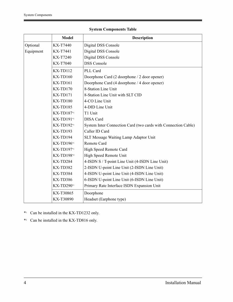
System Components Table
Model Description
Service Unit KX-TD816
KX-TD1232
Digital Super Hybrid System (Main Unit)
Digital Super Hybrid System (Main Unit)
Telephone KX-T7420
KX-T7425
KX-T7431
KX-T7433
KX-T7436
KX-T7320
KX-T7335
KX-T7350
KX-T7220
KX-T7230
KX-T7235
KX-T7250
KX-T7130
KX-T7135
KX-T7020
KX-T7030
KX-T7050
KX-T7055
KX-T7051
KX-T7052
Digital proprietary telephone
Digital proprietary telephone
Digital proprietary telephone with 1-line display
Digital proprietary telephone with 3-line display
Digital proprietary telephone with 6-line display
Proprietary telephone
Proprietary telephone with backlit display
Proprietary telephone
Digital proprietary telephone
Digital proprietary telephone with 2-line display
Digital proprietary telephone with 6-line display
Digital proprietary telephone
Proprietary telephone with display
Proprietary telephone with backlit display
Proprietary telephone
Proprietary telephone with display
Proprietary telephone
Proprietary telephone
Single line telephone
Single line telephone
Installation Manual 3
System Components
Optional
Equipment
KX-T7440
KX-T7441
KX-T7240
KX-T7040
Digital DSS Console
Digital DSS Console
Digital DSS Console
DSS Console
KX-TD112
KX-TD160
KX-TD161
KX-TD170
KX-TD171
KX-TD180
KX-TD185
KX-TD187*1
KX-TD191*1
KX-TD192*1
KX-TD193
KX-TD194
KX-TD196*1
KX-TD197*1
KX-TD198*2
KX-TD284
KX-TD382
KX-TD384
KX-TD386
KX-TD290*1
PLL Card
Doorphone Card (2 doorphone / 2 door opener)
Doorphone Card (4 doorphone / 4 door opener)
8-Station Line Unit
8-Station Line Unit with SLT CID
4-CO Line Unit
4-DID Line Unit
T1 Unit
DISA Card
System Inter Connection Card (two cards with Connection Cable)
Caller ID Card
SLT Message Waiting Lamp Adaptor Unit
Remote Card
High Speed Remote Card
High Speed Remote Unit
4-ISDN S / T-point Line Unit (4-ISDN Line Unit)
2-ISDN U-point Line Unit (2-ISDN Line Unit)
4-ISDN U-point Line Unit (4-ISDN Line Unit)
6-ISDN U-point Line Unit (6-ISDN Line Unit)
Primary Rate Interface ISDN Expansion Unit
KX-T30865
KX-T30890
Doorphone
Headset (Earphone type)
*1 Can be installed in the KX-TD1232 only.
*2 Can be installed in the KX-TD816 only.
System Components Table
Model Description
4 Installation Manual

Important Safety Instructions
Important Safety InstructionsWhen using your telephone equipment, basic safety precautions should always be followed to reduce the risk of fire, electric shock and injury to persons, including the following:
a) Read and understand all instructions.
b) Follow all warnings and instructions marked on the product.
c) Unplug this product from the wall outlet before cleaning. Do not use liquid cleaners or aerosol cleaners. Use a damp cloth for cleaning.
d) Do not use this product near water, for example, near a bathtub, wash bowl, kitchen sink, or laundry tub, in a wet basement, or near a swimming pool.
e) Do not place this product on an unstable cart, stand, or table. The product may fall, causing serious damage to the product.
f) Slots and openings in the cabinet and the back or bottom are provided for ventilation, to protect it from overheating, these openings must not be blocked or covered. The openings should never be blocked by placing the product on the bed, sofa, rug, or other similar surface. This product should never be placed near or over a radiator or heat register. This product should not be placed in a built-in installation unless proper ventilation is provided.
g) This product should be operated only from the type of power source indicated on the marking label. If you are not sure of the type of power supply to your home, consult your dealer or local power company.
h) This product is equipped with a three wire grounding type plug, a plug having a third (grounding) pin. This plug will only fit into a grounding type power outlet. This is a safety feature. If you are unable to insert the plug into the outlet, contact your electrician to replace your obsolete outlet. Do not defeat the safety purpose of the grounding type plug.
i) Do not allow anything to rest on the power cord. Do not locate this product where the cord will be abused by people walking on it.
j) Do not overload wall outlets and extension cords as this can result in the risk of fire or electric shock.
k) Never push objects of any kind into this product through cabinet slots as they may touch dangerous voltage points or short out parts that could result in a risk of fire or electric shock. Never spill liquid of any kind on the product.
l) To reduce the risk of electric shock, do not disassemble this product, but take it to a qualified serviceman when some service or repair work is required. Opening or removing covers may expose you to dangerous voltages or other risks. Incorrect reassembly can cause electric shock when the appliance is subsequently used.
m)Unplug this product from the wall outlet and refer servicing to qualified service personnel under the following conditions:
1) When the power supply cord or plug is damaged or frayed.
2) If liquid has been spilled into the product.
3) If the product has been exposed to rain or water.
Installation Manual 5

Important Safety Instructions
4) If the product does not operate normally by following the operating instructions. Adjust only those controls, that are covered by the operating instructions because improper adjustment of other controls may result in damage and will often require extensive work by a qualified technician to restore the product to normal operation.
5) If the product has been dropped or the cabinet has been damaged.
6) If the product exhibits a distinct change in performance.
n) Avoid using a telephone (other than a cordless type) during an electrical storm. There may be a remote risk of electric shock from lightning.
o) Do not use the telephone to report a gas leak in the vicinity of the leak.
SAVE THESE INSTRUCTIONS
6 Installation Manual

Attention
Attention• Keep the unit away from heating appliances and electrical noise generating devices such as
fluorescent lamps, motors and televisions. These noise sources can interfere with the performance of the Digital Super Hybrid System.
• This unit should be kept free of dust, moisture, high temperature (more than 40°C / 104°F) and vibration, and should not be exposed to direct sunlight.
• Never attempt to insert wires, pins, etc. into the vents or other holes of this unit.
• If there is any trouble, disconnect the unit from the telephone line. Plug the telephone directly into the telephone line. If the telephone operates properly, do not reconnect the unit to the line until the trouble has been repaired by an authorized Panasonic Factory Service Center. If the telephone does not operate properly, chances are that the trouble is in the telephone system, and not in the unit.
• Do not use benzine, thinner, or the like, or any abrasive powder to clean the cabinet. Wipe it with a soft cloth.
WARNINGTHIS UNIT MAY ONLY BE INSTALLED AND SERVICED BY QUALIFIED SERVICE PERSONNEL.
WHEN A FAILURE OCCURS WHICH RESULTS IN THE INTERNAL PARTS BECOMING ACCESSIBLE, DISCONNECT THE POWER SUPPLY CORD IMMEDIATELY AND RETURN THIS UNIT TO YOUR DEALER.
DISCONNECT THE TELECOM CONNECTION BEFORE DISCONNECTING THE POWER CONNECTION PRIOR TO RELOCATING THE EQUIPMENT, AND RECONNECT THE POWER FIRST.
THIS UNIT IS EQUIPPED WITH AN EARTHING CONTACT PLUG. FOR SAFETY REASONS THIS PLUG MUST ONLY BE CONNECTED TO AN EARTHING CONTACT SOCKET WHICH HAS BEEN INSTALLED ACCORDING TO REGULATIONS.
THE POWER SUPPLY CORD IS USED AS THE MAIN DISCONNECT DEVICE, ENSURE THAT THE SOCKET-OUTLET IS LOCATED / INSTALLED NEAR THE EQUIPMENT AND IS EASILY ACCESSIBLE.
TO PREVENT FIRE OR SHOCK HAZARD, DO NOT EXPOSE THIS PRODUCT TO RAIN OR MOISTURE.
Installation Manual 7

Attention
Accessory Order Information • Replacement parts and accessories are available through your local authorized parts
distributor.
• For ordering accessories, call toll free: 1-800-332-5368.
W:White B:Black
When you ship the productCarefully pack and send it prepaid, adequately insured and preferably in the original carton. Attach a postage-paid letter, detailing the symptom, to the outside of the carton. DO NOT send the product to the Executive or Regional Sales offices. They are NOT equipped to make repairs.
Product servicePanasonic Factory Servicenters for this product are listed in the servicenter directory. Consult your authorized Panasonic dealer for detailed instructions.
Part No. Picture Description Comment
KX-J07W/B
KX-J15W/B
KX-J25W/BHandset cord
213.36 cm (7 feet)
457.2 cm (15 feet)
762 cm (25 feet)
The serial number of this product may be found on the label affixed to the bottomof the unit. You should note the model number and the serial number of this unit in the space provided and retain this book as a permanent record of your purchase to aid in identification in the event of theft.
MODEL NO.:
SERIAL NO.:
DATE OF PURCHASE
NAME OF DEALER
DEALER’S ADDRESS
DEALER’S TEL NO.
For your future reference
8 Installation Manual

Introduction
IntroductionThis Installation Manual provides technical information for the Panasonic Digital Super Hybrid System, KX-TD816 / KX-TD1232. It is designed to serve as an overall technical reference for the system and includes a description of the system, its hardware and software, features and services and environmental requirements.
This manual contains the following sections:
Section 1, System OutlineProvides general information on the system including system capacity and specifications.
Section 2, General InstallationContains the basic system installation and wiring instructions, as well as how to install the optional cards and units.
Section 3, ISDN InstallationContains the ISDN unit installation and wiring instructions.
Section 4, T1 InstallationContains the T1 unit installation and wiring instructions.
Section 5, TroubleshootingProvides information for system and telephone troubleshooting.
Section 6, IndexProvides the important words and phrases to help you access the required information easily.
Programming Guide ReferencesThe related and required programming titles described in the Programming Guide are noted for your reference.Programming Guide reference is also shown in the sentences as follows.Example: <SYS PRG [109]>Explanation: Refer to system program [109] in the Programming Guide.This helps you know the related and required programming easily for the contents of the sentences.
Features Guide ReferencesThe related feature titles described in the Features Guide are noted for your reference.
Terms used in this Installation Manual
Installation Manual 9

Introduction
Along with this Installation Manual, the following manuals are available to help you know the available features, program and use the KX-TD816 / KX-TD1232 system.
Features GuideProvides information about the system features.
Programming GuideProvides system programming instructions.
User ManualProvides operating instructions for the end users using proprietary telephones, single line telephones, consoles.
About the other manuals
10 Installation Manual

F.C.C REQUIREMENTS AND RELEVANT INFORMATION
F.C.C REQUIREMENTS AND RELEVANT INFORMATION
1. Notification to the Telephone Company
This equipment complies with Part 68 of the FCC rules and the requirements adopted by the ACTA. On the bottom of this equipment is a label that contains, among other information, a product identifier in the format US: XXXXX##XXXXX. If requested, this number must be provided to the telephone company.
Installation must be performed by a qualified professional installer. If required, provide the telephone company with the following technical information:
• Telephone numbers to which the system will be connected
• Make: Panasonic
• Model: KX-TD816 / KX-TD1232
• FCC Registration No.: found on the bottom of the unit
• Ringer Equivalence No.: 0.4B
• Facility Interface Code: 02LS2, 02RV2-T, 02IS5
• Service Order Code: 9.0F, AS.2, 6.0P
• Required Network Interface Jack: RJ11 / 14C, RJ49
2. Ringer Equivalence Number (REN)
The REN is used to determine the number of devices that may be connected to a telephone line. Excessive RENs on a telephone line may result in the devices not ringing in response to an incoming call. In most, but not all areas, the sum of RENs should not exceed five (5.0). To be certain of the number of devices that may be connected to a line, as determined by the total RENs, contact the local telephone company. The REN for this product is part of the product identifier that has the format US: XXXXX##XXXXX. The digits represented by ## are the REN without a decimal point (e.g., 03 is a REN of 0.3). For earlier products, the REN is separately shown on the label.
3. Incidence of Harm to the Telephone Lines
If this equipment causes harm to the telephone network, the telephone company will notify you in advance that temporary discontinuance of service may be required. But if advance notice isn't practical, the telephone company will notify the customer as soon as possible. Also, you will be advised of your right to file a complaint with the FCC if you believe it is necessary.
4. Changes in Telephone Company Communications Facilities, Equipment, Operations and Procedures
The telephone company may make changes in its facilities, equipment, operations or procedures that could affect the operation of the equipment. If this happens the telephone company will provide advance notice in order for you to make necessary modifications to maintain uninterrupted service.
Installation Manual 11

F.C.C REQUIREMENTS AND RELEVANT INFORMATION
5. Trouble with This Equipment
If trouble is experienced with this equipment, for repair or warranty information, please see the attached warranty, which includes the Servicenter Directory. If the equipment is causing harm to the telephone network, the telephone company may request that you disconnect the equipment until the problem is resolved.
6. Connection to Party Line
Connection to party line service is subject to state tariffs. Contact the state public utility commission, public service commission or corporation commission for information.
Note
Allowing this equipment to be operated in such a manner as to not provide for proper answer supervision is a violation of Part 68 of the FCC's rules.
Proper answer supervision is when:
This equipment returns answer supervision to the public switched telephone network (PSTN) when DID calls are:
—Answered by the called station—Answered by the attendant—Routed to a recorded announcement that can be administered by the customer
premises equipment (CPE) user.—Routed to a dial prompt
This equipment returns answer supervision on all DID calls forwarded to the PSTN Permissible exceptions are:
—A call is unanswered—A busy tone is received—A reorder tone is received
This equipment has been tested and found to comply with the limits for a Class A digital device, pursuant to Part 15 of the FCC Rules. These limits are designed to provide reasonable protection against harmful interference when the equipment is operated in a commercial environment. This equipment generates, uses, and can radiate radio frequency energy and, if not installed and used in accordance with the instruction manual, may cause harmful interference to radio communications. Operation of this equipment in a residential area is likely to cause harmful interference in which case the user will be required to correct the interference at his own expense.
12 Installation Manual

F.C.C REQUIREMENTS AND RELEVANT INFORMATION
CAUTIONAny changes or modifications not expressly approved by the party responsible for compliance could void the user's authority to operate this device.
When programming emergency numbers and / or making test calls to emergency numbers:1. Remain on the line and briefly explain to the dispatcher the reason for the call before hanging up.2. Perform such activities in the off-peak hours, such as early morning hours or late evenings.
WARNINGThe software contained in the ARS and TRS features to allow user access to the network must be upgraded to recognize newly established network area codes and exchange codes as they are placed into service. Failure to upgrade the premises PBXs or peripheral equipment to recognize the new codes as they are established will restrict the customer and the customer's employees from gaining access to the network and to these codes. KEEP THE SOFTWARE UP-TO-DATE WITH THE LATEST DATA.
Installation Manual 13
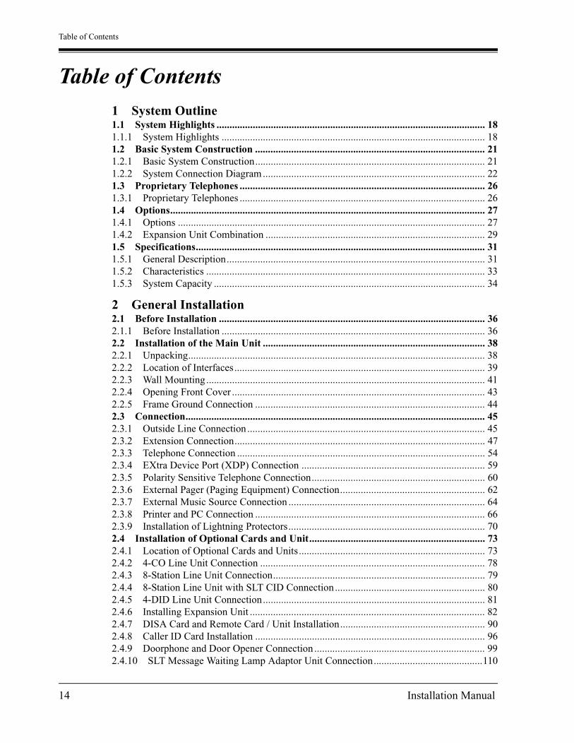
Table of Contents
Table of Contents
1 System Outline1.1 System Highlights ........................................................................................................ 181.1.1 System Highlights ...................................................................................................... 181.2 Basic System Construction ......................................................................................... 211.2.1 Basic System Construction......................................................................................... 211.2.2 System Connection Diagram...................................................................................... 221.3 Proprietary Telephones ............................................................................................... 261.3.1 Proprietary Telephones ............................................................................................... 261.4 Options.......................................................................................................................... 271.4.1 Options ....................................................................................................................... 271.4.2 Expansion Unit Combination ..................................................................................... 291.5 Specifications................................................................................................................ 311.5.1 General Description.................................................................................................... 311.5.2 Characteristics ............................................................................................................ 331.5.3 System Capacity ......................................................................................................... 34
2 General Installation2.1 Before Installation ....................................................................................................... 362.1.1 Before Installation ...................................................................................................... 362.2 Installation of the Main Unit ...................................................................................... 382.2.1 Unpacking................................................................................................................... 382.2.2 Location of Interfaces................................................................................................. 392.2.3 Wall Mounting............................................................................................................ 412.2.4 Opening Front Cover .................................................................................................. 432.2.5 Frame Ground Connection ......................................................................................... 442.3 Connection.................................................................................................................... 452.3.1 Outside Line Connection ............................................................................................ 452.3.2 Extension Connection................................................................................................. 472.3.3 Telephone Connection ................................................................................................ 542.3.4 EXtra Device Port (XDP) Connection ....................................................................... 592.3.5 Polarity Sensitive Telephone Connection................................................................... 602.3.6 External Pager (Paging Equipment) Connection........................................................ 622.3.7 External Music Source Connection ............................................................................ 642.3.8 Printer and PC Connection ......................................................................................... 662.3.9 Installation of Lightning Protectors............................................................................ 702.4 Installation of Optional Cards and Unit.................................................................... 732.4.1 Location of Optional Cards and Units........................................................................ 732.4.2 4-CO Line Unit Connection ....................................................................................... 782.4.3 8-Station Line Unit Connection.................................................................................. 792.4.4 8-Station Line Unit with SLT CID Connection.......................................................... 802.4.5 4-DID Line Unit Connection...................................................................................... 812.4.6 Installing Expansion Unit ........................................................................................... 822.4.7 DISA Card and Remote Card / Unit Installation........................................................ 902.4.8 Caller ID Card Installation ......................................................................................... 962.4.9 Doorphone and Door Opener Connection .................................................................. 992.4.10 SLT Message Waiting Lamp Adaptor Unit Connection..........................................110
14 Installation Manual
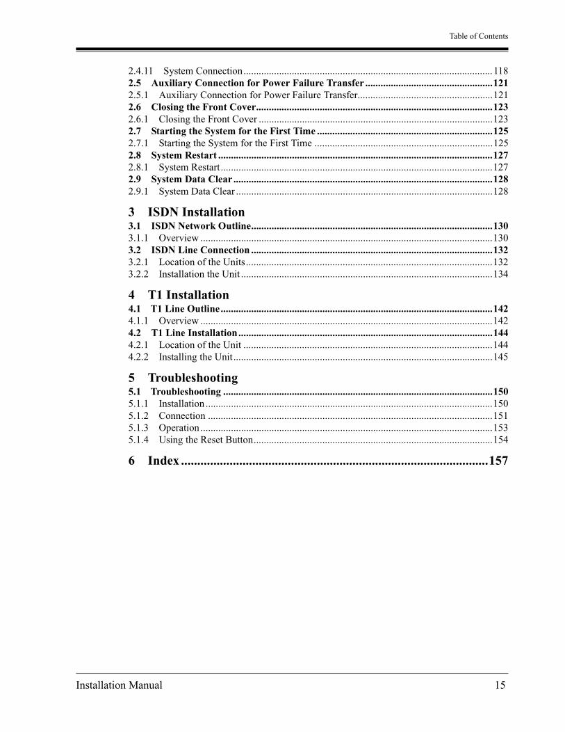
Table of Contents
2.4.11 System Connection..................................................................................................1182.5 Auxiliary Connection for Power Failure Transfer ..................................................1212.5.1 Auxiliary Connection for Power Failure Transfer.....................................................1212.6 Closing the Front Cover.............................................................................................1232.6.1 Closing the Front Cover ............................................................................................1232.7 Starting the System for the First Time .....................................................................1252.7.1 Starting the System for the First Time ......................................................................1252.8 System Restart ............................................................................................................1272.8.1 System Restart...........................................................................................................1272.9 System Data Clear ......................................................................................................1282.9.1 System Data Clear .....................................................................................................128
3 ISDN Installation3.1 ISDN Network Outline...............................................................................................1303.1.1 Overview ...................................................................................................................1303.2 ISDN Line Connection ...............................................................................................1323.2.1 Location of the Units.................................................................................................1323.2.2 Installation the Unit ...................................................................................................134
4 T1 Installation4.1 T1 Line Outline...........................................................................................................1424.1.1 Overview ...................................................................................................................1424.2 T1 Line Installation....................................................................................................1444.2.1 Location of the Unit ..................................................................................................1444.2.2 Installing the Unit......................................................................................................145
5 Troubleshooting5.1 Troubleshooting ..........................................................................................................1505.1.1 Installation .................................................................................................................1505.1.2 Connection ................................................................................................................1515.1.3 Operation ...................................................................................................................1535.1.4 Using the Reset Button..............................................................................................154
6 Index ...............................................................................................157
Installation Manual 15

Table of Contents
16 Installation Manual

System Outline
Section 1
System Outline
This section provides general information on the system, including system capacity and specifications.
Installation Manual 17

System Outline
1.1 System Highlights
1.1.1 System Highlights
System Maximum Capacity
Module Expansion Expansion modules are used to increase the system capacity.
EXtra Device Port (XDP) Each extension jack in the system supports the connection of a digital proprietary telephone / DSS Console and a single line device. The two devices per jack have different extension numbers and are treated as two completely different extensions.
Paralleled Telephone Connection Every jack in the system also supports the parallel connection of a proprietary telephone and a single line device. They share the same extension number and are considered by the system to be one extension.
Super Hybrid System This system supports the connection of digital and analog proprietary telephones, DSS Consoles and single line devices such as single line telephones, fax machines, and data terminals.
KX-TD816 KX-TD1232 KX-TD1232x2
Extension
PT&SLT 16 (32) 32 (64) 64 (128)
ISDN telephone*1
*1 Installing BRI unit, PRI unit and T1 unit together is impossible.
4 BRI (8 ch) 6 BRI (12 ch) 12 BRI (24 ch)
T1 Extension (OPX)*1
0 24 24
Outside Line
Analog 8 12 24
Basic Rate Interface (BRI)*1
4 BRI (8 ch) 6 BRI (12 ch) 12 BRI (24 ch)
Primary Rate Interface (PRI)*1
0 1 PRI (23 ch) 1 PRI (23 ch)
T1 Lines*1 0 24 24
18 Installation Manual

System Outline
System Connection*1
With the addition of the optional System Inter Connection Card, two Digital Super Hybrid Systems can be connected together to expand the system to a maximum of 24 outside lines and 64 extensions. The two systems function as one, therefore, some functions such as paging and music-on-hold are duplicated.
ISDN Line ServiceThe system can manage a call received from the ISDN line by point-to-point or point-to-multi-point configuration. To use this service, an optional unit is required.
TIE Line ServiceA TIE line is a privately leased communication line between two or more PBXs, which provides cost effective communications between company at different locations. To use this service, an optional unit is required.
T1 Line ServiceA T1 line is at the bottom of the digital transmission hierarchy. The T1 line contains 24 voice channels. Voice is digitized by Pulse Code Modulation. To use this service, an optional unit is required.
Digital Proprietary Telephones (DPT) The system supports four different models of digital proprietary telephones which cover the range from a monitor set to a large display handsfree version.
Programming System The system can be programmed from a proprietary telephone or from a personal computer.
Voice Mail Integration The system supports Voice Processing Systems with in-band DTMF signaling as well as DPT integration. The Panasonic Voice Processing System provides automated attendant, voice mail, interview and custom services.
Automatic Route Selection (ARS) Automatically selects the pre-programmed least expensive route for outgoing toll calls.
*1 Available for the KX-TD1232 only.
Installation Manual 19

System Outline
Caller IDAllows the user to see the name or telephone number of a caller on the telephone display before answering a call.
Trunk (Outside Line) Answer From Any Station (TAFAS) Ringing occurs over the external paging system; the call can be answered from any station.
Remote Station Lock Control Allows an operator to lock an extension so that outgoing calls cannot be made.
Uniform Call Distribution (UCD)Allows incoming calls to be distributed uniformly to a specific group of extensions.
20 Installation Manual

System Outline
1.2 Basic System Construction
1.2.1 Basic System Construction
The KX-TD816 Digital Super Hybrid System has a basic capacity of four outside lines and eight extensions, and the KX-TD1232 has eight outside lines and 16 extensions. They are capable of supporting Panasonic digital and analog proprietary telephones, DSS Consoles and single line devices such as single line telephones and fax machines. To expand its capabilities, the system can be equipped with optional components or customer-supplied peripherals such as external speakers and external music sources (e.g., radios).
D1232DIGITAL SUPER HYBRID SYSTEM
PanasonicPanasonic
D816DIGITAL SUPER HYBRID SYSTEM
Installation Manual 21

System Outline
1.2.2 System Connection Diagram
KX-TD816
Panasonic
D816DIGITAL SUPER HYBRID SYSTEM
Avoid using the same ACoutlet for office equipmentand the KX-TD816. Use adedicated AC outlet only.
External Music Source
Amplifier Speaker
Printer for SMDR or Personal Computer for System Programming
120 VAC, 60 Hz
AC Surge Protector
22 Installation Manual

System Outline
Note
• It is recommended that extension of jack 1 is a display proprietary telephone.
• Parallel connection of telephones is possible. Refer to the Parallel Telephone Connection in 2.3.3 Telephone Connection.
D816DEGITAL SUPER HYBRID SYSTEM
Panasonic
KX-T7400 series digitalproprietary telephones
Digital DSS consoles(KX-T7440 / KX-T7441/ KX-T7240)
KX-T7200 series digitalproprietary telephones
KX-T7051 / KX-T7052single line telephones
(two pair)
(one pair)
Data Terminal
Single Line Telephone
(Lightning Protectors)to outside lines 1 through 4 (initial) to outside lines 5 through 8 (additional)8 Outside Lines
16 Extensions (8 extensions – initial, 8 extensions – additional)
Cordless Phone
(one pair)
(one pair)
KX-T7040 DSS console
(one pair)
(twopair)
(onepair)
(onepair)
(onepair)
(onepair)
KX-T7000 series analogproprietary telephones
(twopair)
(twopair)
KX-T7130 analogproprietary telephone
Telephone AnsweringMachine with Facsimile
Voice Processing System
SLT Message Waiting Lamp Adaptor Unit KX-TD194
Panasonic
Panasonic
: needs Optional Cards or Adaptor.
Panasonic Panasonic
Doorphone 1
Doorphone KX-T30865
Doorphone 2
Panasonic Panasonic
Doorphone 3 Doorphone 4
Door Opener 1 Door Opener 2
Door Opener 3 Door Opener 4
Installation Manual 23

System Outline
KX-TD1232
D1232DIGITAL SUPER HYBRID SYSTEM
Panasonic
Printer for SMDR or Personal Computer for System Programming
AC Surge Protector
120 VAC, 60 Hz
Avoid using the same ACoutlet for office equipmentand the KX-TD1232. Use adedicated AC outlet only.
External Music Source 1
External Music Source 2
Amplifier Speaker 1
Amplifier Speaker 2
24 Installation Manual

System Outline
Note
• It is recommended that extension of jack 1 is a display proprietary telephone.
• Parallel connection of telephones is possible. Refer to the Parallel Telephone Connection in 2.3.3 Telephone Connection.
Panasonic Panasonic
Doorphone 1
Doorphone KX-T30865
Doorphone 2
Panasonic Panasonic
Doorphone 3 Doorphone 4
Door Opener 1 Door Opener 2
Door Opener 3 Door Opener 4
: needs Optional Cards or Adaptor.
Panasonic
Panasonic
KX-T7400 series digitalproprietary telephones
Digital DSS consoles(KX-T7440 / KX-T7441/ KX-T7240)
KX-T7200 series digitalproprietary telephones
KX-T7051 / KX-T7052single line telephones
(two pair)
(one pair)
Data Terminal
Single Line Telephone
(Lightning Protectors)to outside lines 1 through 8 (initial) to outside lines 9 through 12 (additional)12 Outside Lines
32 Extensions (16 extensions – initial, 16 extensions – additional)
Cordless Phone
(one pair)
(one pair)
KX-T7040 DSS console
(one pair)
(twopair)
(onepair)
(onepair)
(onepair)
(onepair)
KX-T7000 series analogproprietary telephones
(twopair)
(threepair)
KX-T7130 analogproprietary telephone
Telephone AnsweringMachine with Facsimile
Voice Processing System
SLT Message Waiting Lamp Adaptor Unit KX-TD194
D1232DEGITAL SUPER HYBRID SYSTEM
Panasonic
Installation Manual 25

System Outline
1.3 Proprietary Telephones
1.3.1 Proprietary Telephones
The following Panasonic proprietary telephones are available with this system.
Note
Flexible CO : Flexible CO button (programmable)
PF : Programmable Feature button
ProprietaryTelephone
Description
KX-T7420 Digital, speakerphone, 12 Flexible CO
KX-T7425 Digital, speakerphone, 24 Flexible CO
KX-T7431 Digital, 1-line display, speakerphone, 12 Flexible CO
KX-T7433 Digital, 3-line display, speakerphone, 24 Flexible CO
KX-T7436 Digital, 6-line display, speakerphone, 24 Flexible CO
KX-T7320 Speakerphone, 12 Flexible CO
KX-T7335 1-line backlit display, speakerphone, 12 Flexible CO
KX-T7350 Monitor, 12 Flexible CO
KX-T7220 Digital, speakerphone, 24 Flexible CO
KX-T7230 Digital, 2-line display, speakerphone, 24 Flexible CO
KX-T7235 Digital, 6-line display, speakerphone, 12 Flexible CO
KX-T7250 Digital, monitor, 6 Flexible CO
KX-T7130 1-line display, speakerphone, 12 Flexible CO, 12 PF
KX-T7135 1-line backlit display, speakerphone, 12 Flexible CO, 12 PF
KX-T7020 Speakerphone, 12 Flexible CO, 4 PF
KX-T7030 1-line display, speakerphone, 12 Flexible CO, 4 PF
KX-T7050 Monitor, 12 Flexible CO, 4 PF
KX-T7055 Monitor, 3 Flexible CO, 3 PF
26 Installation Manual

System Outline
1.4 Options
1.4.1 Options
Model No. Model Name Description
Max.Quantity
onKX-
TD816
Max. Quantity onKX-TD1232
SingleSystem
SystemConnection
KX-TD170 8-Station Line Unit Adds 8 extension lines. 1 2 4
KX-TD171 8-Station Line Unit with SLT CID
Adds 8 extension lines which contain single line telephones CID.
1 2 4
KX-TD180 4-CO Line Unit Adds 4 outside lines. 1 1 2
KX-TD185 4-DID Line Unit Adds 4 DID lines. 1 1 2
KX-TD187 T1 Unit Adds 1 T1 line. — 1 1
KX-TD382 2-ISDN Unit Adds 2 ISDN U-point lines.
1 1 2
KX-TD384 4-ISDN Unit Adds 4 ISDN U-point lines.
1 1 2
KX-TD386 6-ISDN Unit Adds 6 ISDN U-point lines.
1 1 2
KX-TD284 4-ISDN Unit Adds 4 ISDN S / T-point lines.
1 1 2
KX-TD290 Primary Rate Interface ISDN Expansion Unit
Adds 1 PRI ISDN line. — 1 1
KX-TD191 DISA Card Supports the Direct Inward System Access (DISA) feature and records outgoing messages.
— 1 2
KX-TD192 System Inter Connection Card
Connects two Digital Super Hybrid Systems.
— — 2
KX-TD193 Caller ID Card Supports the Caller ID Service of the central office.
2 3 6
Installation Manual 27

System Outline
KX-TD194 SLT Message Waiting Lamp Adaptor Unit
Supports the Message Waiting feature for a single line telephone with a message waiting lamp. One unit supoorts 16 extensions.
1 2 4
KX-TD196 Remote Card Supports the programming and maintenance of the system from a remote location.
— 1 2
KX-TD197 High Speed Remote Card
Supports the programming and maintenance of the system from a remote location.
— 1 2
KX-TD198 High Speed Remote Unit
Supports the programming and maintenance of the system from a remote location.
1 — —
KX-TD112 PLL Card Synchronizes the system clock with the clock of the ISDN network.
1 1 1(Master Only)
KX-TD160 Doorphone Card Supports 2 doorphones and 2 door openers.
1 1 2
KX-TD161 Doorphone Card Supports 4 doorphones and 4 door openers.
1 1 2
KX-T7440 /
KX-T7441 /
KX-T7240 /
KX-T7040 /
DSS Console Provides easy and quick access to extensions and features. This must be used with a proprietary telephone.
4 4 8
KX-T30865 Doorphone Used for a doorphone call.
2 2 4
Model No. Model Name Description
Max.Quantity
onKX-
TD816
Max. Quantity onKX-TD1232
SingleSystem
SystemConnection
28 Installation Manual

System Outline
1.4.2 Expansion Unit Combination
KX-TD816
KX-TD1232 Master System
Basic (no unit connected)
+ KX-TD17x
+ KX-TD180 / KX-TD185
+ KX-TD284
+ KX-TD38x
KX-TD38xKX-TD284KX-TD180 /KX-TD185KX-TD17x
Basic (no unit connected)
+ KX-TD17x
+ KX-TD180 / KX-TD185
+ KX-TD187
+ KX-TD284
+ KX-TD38x
+ KX-TD290
+ KX-TD17x + KX-TD17x
+ KX-TD17x + KX-TD180 /
KX-TD185
+ KX-TD17x + KX-TD187
+ KX-TD17x + KX-TD284
+ KX-TD17x + KX-TD38x
+ KX-TD17x + KX-TD290
KX-TD284KX-TD187KX-TD17x KX-TD38x KX-TD290KX-TD180 /KX-TD185
Installation Manual 29
System Outline
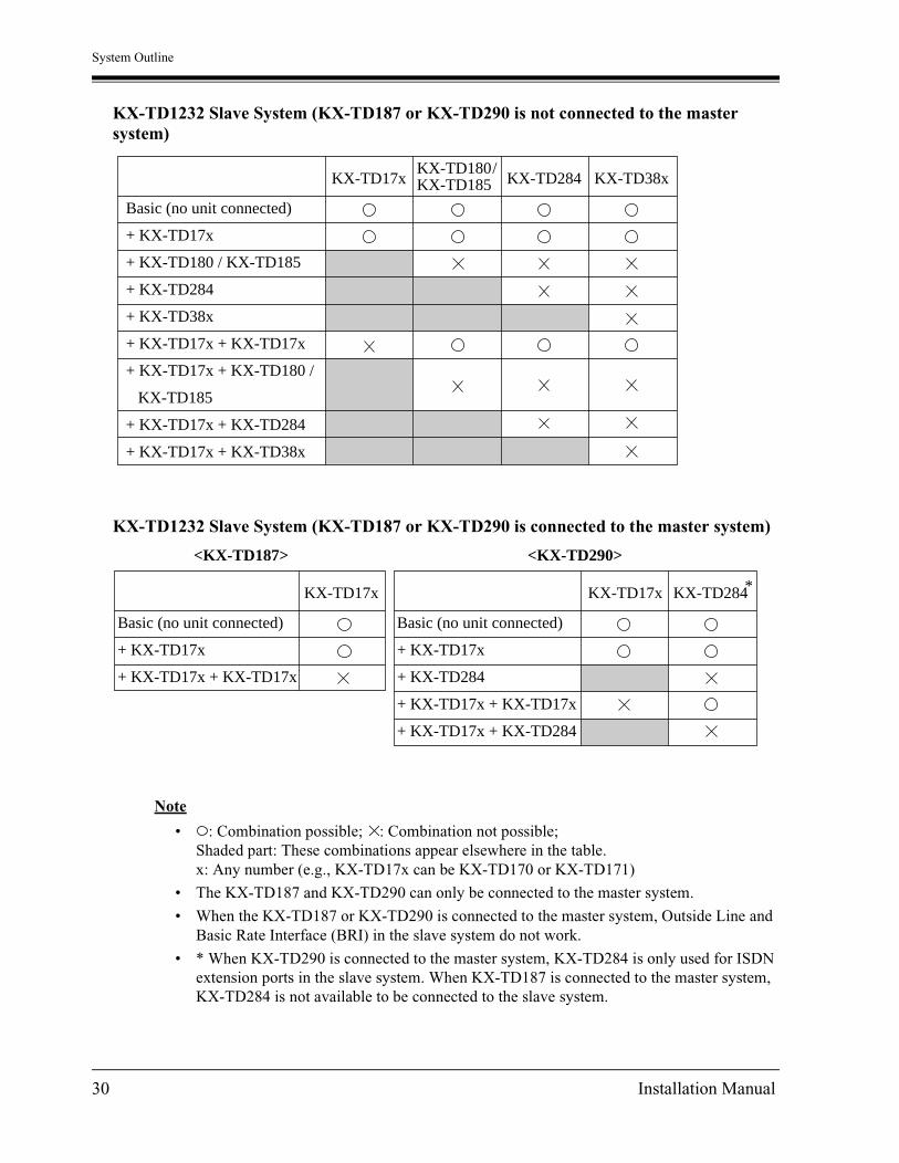
KX-TD1232 Slave System (KX-TD187 or KX-TD290 is not connected to the master system)
KX-TD1232 Slave System (KX-TD187 or KX-TD290 is connected to the master system)
Note
• : Combination possible; : Combination not possible;Shaded part: These combinations appear elsewhere in the table.x: Any number (e.g., KX-TD17x can be KX-TD170 or KX-TD171)
• The KX-TD187 and KX-TD290 can only be connected to the master system.
• When the KX-TD187 or KX-TD290 is connected to the master system, Outside Line and Basic Rate Interface (BRI) in the slave system do not work.
• * When KX-TD290 is connected to the master system, KX-TD284 is only used for ISDN extension ports in the slave system. When KX-TD187 is connected to the master system, KX-TD284 is not available to be connected to the slave system.
Basic (no unit connected)
+ KX-TD17x
+ KX-TD180 / KX-TD185
+ KX-TD284
+ KX-TD38x
+ KX-TD17x + KX-TD17x
+ KX-TD17x + KX-TD180 /
KX-TD185
+ KX-TD17x + KX-TD284
+ KX-TD17x + KX-TD38x
KX-TD38xKX-TD284KX-TD17xKX-TD180 /KX-TD185
Basic (no unit connected)
+ KX-TD17x
+ KX-TD17x + KX-TD17x
KX-TD17x
Basic (no unit connected)
+ KX-TD17x
+ KX-TD284
+ KX-TD17x + KX-TD17x
+ KX-TD17x + KX-TD284
KX-TD17x KX-TD284*
<KX-TD290><KX-TD187>
30 Installation Manual

System Outline
1.5 Specifications
1.5.1 General Description
Control Method CPU: 16-bit CPU
Switching Non Blocking PCM Time Switch
Power Supplies Primary 120 V AC, 60 Hz
Secondary Station Supply Volt: 30 VCircuit Volt: 5 V, 15 V
Power Failure • Memory backup duration: seven years with a factory-provided lithium battery
• 4 outside lines max. for KX-TD816 and 6 outside lines max. for KX-TD1232 automatic transfer to extensions (Power Failure Transfer)
Dialing Outward Dial Pulse (DP) 10 pps, 20 ppsTone (DTMF) Dialing
Internal Dial Pulse (DP) 10 pps, 20 ppsTone (DTMF) Dialing
Connectors Outside lines Modular Jack (RJ14C)
Extensions KX-TD816: Modular JackKX-TD1232: Amphenol Connector
Paging Output Pin Jack (RCA JACK)
ExternalMusic Input
Two-conductor Jack (MINIJACK 3.5 mm diameter)
Extension Connection Cable Single line telephones 1 pair wire (T, R)
KX-T7420, KX-T7425, KX-T7431,KX-T7433, KX-T7436, KX-T7220,KX-T7230, KX-T7235, KX-T7250
1 pair wire (D1, D2) or2 pair wire (T, R, D1, D2)
KX-T7130, KX-T7135 (with the KX-TD816),KX-T7320, KX-T7335, KX-T7350,KX-T7020, KX-T7030, KX-T7050,KX-T7055
2 pair wire (T, R, D1, D2)
KX-T7130, KX-T7135 (with the KX-TD1232)
3 pair wire (T, R, D1, D2, P1, P2)
KX-T7440, KX-T7441, KX-T7240,KX-T7040
1 pair wire (D1, D2)
Installation Manual 31
System Outline
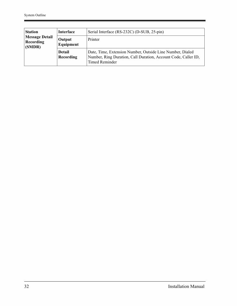
StationMessage DetailRecording(SMDR)
Interface Serial Interface (RS-232C) (D-SUB, 25-pin)
OutputEquipment
Printer
DetailRecording
Date, Time, Extension Number, Outside Line Number, Dialed Number, Ring Duration, Call Duration, Account Code, Caller ID, Timed Reminder
32 Installation Manual

System Outline
1.5.2 Characteristics
Station Loop Limit Proprietary Telephone: 40 Single Line Telephone: 600 including setDoorphone: 20
Minimum Leakage Resistance 15 000
Maximum Number of Station Instruments per Line
1 for proprietary telephone or single line telephone
2 by Parallel or eXtra Device Port Connection of a proprietary telephone and a single line telephone
Ring Voltage 70 Vrms at 20 Hz depending on the Ringing Load
Central Office Loop Limit 1 600 max.
Environmental Requirements 0 °C – 40 °C (32 °F – 104 °F), 10 % – 90 % relative humidity
Hooks witch Flash Timing Range
200 ms – 1000 ms
Installation Manual 33

System Outline
1.5.3 System Capacity
Lines, Station EquipmentActual capacity will depend on the number or / and type of units connected to the system.
System Data
Item Max.Quantity onKX-TD816
Max. Quantity onKX-TD1232
SingleSystem
SystemConnection
Doorphones 4 4 8
Door Openers 4 4 8
External Pagers 1 2 4
External Music Sources 1 2 4
Item Max. Quantity
Operators 2
System Speed Dialing 500
One-Touch Dialing 24 per extension
(proprietary telephone)
Station Speed Dialing 10 per extension
Call Park areas 10
Absent Messages 9
Outside Line Groups 8
Toll Restriction Levels 8
Extension Groups 8
Class of Service levels 8
Message Waitings 128
Uniform Call Distribution Groups 8
34 Installation Manual

General Installation
Section 2
General Installation
Installation Manual 35

General Installation
2.1 Before Installation
2.1.1 Before Installation
Please read the following notes concerning installation and connection before installing the system and terminal equipment.
Safety Installation InstructionsWhen installing telephone wiring, basic safety precautions should always be followed to reduce the risk of fire, electric shock and injury to persons, including the following:
a) Never install telephone wiring during a lightning storm.
b) Never install telephone jacks in wet locations unless the jack is specifically designed for wet locations.
c) Never touch uninsulated telephone wires or terminals unless the telephone line has been disconnected at the network interface.
d) Use caution when installing or modifying telephone lines.
Installation PrecautionsThis system is designed for wall mounting only. Avoid installing in the following places. (Doing so may result in malfunction, noise, or discoloration.)
a) In direct sunlight and hot, cold, or humid places. (Temperature range: 0 °C – 40 °C / 32 °F – 104 °F)
b) Sulfuric gases produced in areas where there are thermal springs, etc., may damage the equipment or contacts.
c) Places in which shocks or vibrations are frequent or strong.
d) Dusty places, or places where water or oil may come into contact with the system.
e) Near high-frequency generating devices such as sewing machines or electric welders.
f) On or near computers, telexes, or other office equipment, as well as microwave ovens or air conditioners. (It is preferable not to install the system in the same room with the above equipment.)
g) Install at least 1.8 m (6 feet) away from radios and televisions. (Both the system and Panasonic proprietary telephones)
h) Do not obstruct area around the system (for reasons of maintenance and inspection — be especially careful to allow space for cooling above and at the sides of the system).
36 Installation Manual

General Installation
Wiring PrecautionsBe sure to follow these instructions when wiring the unit:
a) To assure good quality telephone connection, it is recommended new and modifications to existing installation of customer premise wiring shall use solid twisted pair copper conductors with minimum 24 gauge that comply with the electrical specifications for Category 3 wiring as detailed in ANSI/EIA/TIA-570A Building Wiring Standards.
b) If cables are run on the floor, use protectors to prevent the wires from being stepped on. Avoid wiring under carpets.
c) Avoid using the same power supply outlet for computers, telexes, and other office equipment. Otherwise, the system operation may be interrupted by the induction noise from such equipment.
d) Please use one pair telephone wire for extension connection of (telephone) equipment such as single line telephones, data terminals, answering machines, computers, voice processing systems, etc., except Panasonic proprietary telephones (e.g., KX-T7436, KX-T7235).
e) The Power Switch of the system must be off during wiring. After all of the wiring is completed, turn the Power Switch on.
f) Mis-wiring may cause the system to operate improperly. Refer to 5.1.1 Installation and 5.1.2 Connection.
g) If an extension does not operate properly, disconnect the telephone from the extension line and then connect again, or turn off the Power Switch of the system and then on again.
h) The system is equipped with a 3-wire grounding type plug. This is a safety feature. If you are unable to insert the plug into the outlet, contact your electrician to replace your obsolete outlet. Do not defeat the purpose of the grounding-type plug.
i) Use twisted pair cable for outside line connection.
j) Outside lines should be installed with lightning protectors. For details, refer to 2.3.9 Installation of Lightning Protectors.
WARNINGStatic sensitive devices are used. To protect printed circuit boards from static electricity, do not touch connectors indicated to the right. To discharge body static, touch ground or wear a grounding strap.
REMOTE
SYSTEM INTERCONNECTION
DISA
DOORPHONE
Warning: Static sensitive connectors
Installation Manual 37

General Installation
2.2 Installation of the Main Unit
2.2.1 Unpacking
Unpack the box and check the items below:
KX-TD816 KX-TD1232
Main Unit one one
AC Cord one one
Template one one
Screws (Wall Mounting) three four
Pager Connectors — two
Music Source Connectors — two
Expansion Line Cord Holder one one
38 Installation Manual

General Installation
2.2.2 Location of Interfaces
OverviewKX-TD816
KX-TD1232
D816DIGITAL SUPER HYBRID SYSTEM
Panasonic
External Music Jack
Paging Jack
System Clear Switch
Reset Button
Serial Interface (RS-232C) Connector
Ground Terminal
AC Inlet
Power Switch
Power Indicator
D1232DIGITAL SUPER HYBRID SYSTEM
Panasonic
Serial Interface (RS-232C) Connector
Ground Terminal
AC Inlet
Power Switch
Power Indicator
Installation Manual 39

General Installation
Inside ViewKX-TD816
KX-TD1232
Extension ModularJacks
Outside LineModular Jacks
Fuse
Front Cover
REMOTE
SYSTEM INTERCONNECTION
DISA
DOORPHONE
Outside Line Modular Jacks
Extension Amphenol Connector
Paging Jack 2
Paging Jack 1
External Music Jack 2
External Music Jack 1
System Clear Switch
Reset Button
40 Installation Manual

General Installation
2.2.3 Wall Mounting
This set is designed for wall mounting only. The wall where the main unit is to be mounted must be able to support the weight of the main unit. If screws other than the ones supplied are used, use screws with the same diameter as the ones enclosed.
Mounting on Wooden Wall1. Place the template (included) on the wall to mark the screw positions.
2. Install the screws (included) into the wall.
3. Hook the main unit on the screw heads.
Template Template
KX-TD816 KX-TD1232
Drive the screwto this position
WoodenWall
KX-TD816 KX-TD1232
Installation Manual 41

General Installation
Mounting on Concrete or Mortar Wall1. Place the template (included) on the wall to mark the screw positions.
2. Drill holes and drive the anchor plugs (user-supplied) with a hammer, flush to the wall.
3. Install the screws (included) into the anchor plugs.
4. Hook the main unit on the screw heads.
Template Template
KX-TD816 KX-TD1232
Concrete WallTo the wall surfaceAnchor Plug
29 mm(1 1/8 inch)
6.4 mm(1/4 inch)
Drive the screwto this position
KX-TD816 KX-TD1232
42 Installation Manual

General Installation
2.2.4 Opening Front Cover
1. Loosen the two screws on the right side of the main unit.
2. Open the front cover in the direction of arrow .
Note
The two screws are attached to the front cover with springs so that they will not be lost.
A
D1232DIGITAL SUPER HYBRID SYSTEM
Panasonic
A
Panasonic
D816DIGITAL SUPER HYBRID SYSTEM
A
screw
screw
screw
screw
Installation Manual 43

General Installation
2.2.5 Frame Ground Connection
IMPORTANTConnect the frame of the main unit to ground.
1. Loosen the screw.
2. Insert the grounding wire.
3. Tighten the screw.
4. Connect the grounding wire to ground.
In most of the continental United States, the ground provided by the "Third wire ground" at the commercial power outlet will be satisfactory. However, in a small percentage of cases this ground may be installed incorrectly. Therefore, the following test procedure should be performed.
Test Procedure1. Obtain a suitable voltmeter and set it for a possible reading of up to 250 V AC.
2. Connect the meter probes between the two main AC voltage points on the wall outlet. The reading obtained should be 108 V AC-132 V AC.
3. Move one of the meter probes to the 3rd prong terminal (GND).Either the same reading or a reading of 0 V should be obtained.
4. If a reading of 0 V at one terminal and a reading of 108 V AC-132 V AC at the other terminal is not obtained, the outlet is not properly grounded.This condition should be corrected by a qualified electrician (per article 250 of the National Electrical Code).
5. If a reading of 0 V at one terminal and a reading of 108 V AC-132 V AC at the other terminal is obtained, then set the meter to the "OHMS / RX1" scale, place one probe at the GND Terminal and the other probe at the terminal which gave a reading of 0 V.A reading of less than 1 ohm should be obtained.If the reading is not obtained the outlet is not adequately grounded, see a qualified electrician.
To ground
Panasonic
D816DIGITAL SUPER HYBRID SYSTEM
To ground
D1232DIGITAL SUPER HYBRID SYSTEM
44 Installation Manual

General Installation
2.3 Connection
2.3.1 Outside Line Connection
Connection1. Insert the modular plugs of the telephone line cords (4-conductor wiring) into the modular
jacks on the system.
2. Connect the line cord to the terminal board or the Central Office jack.
KX-TD816
(T1, R1) (T2, R2)
Outside Line 3, Outside Line 4
Outside Line 1, Outside Line 2
T2R1T1R2
View of TEL Jack (Outside Line)
R: Ring T: Tip
Use 4-conductor wiring cord
To Terminal Board or ModularJacks from the Central Office.
Installation Manual 45

General Installation
KX-TD1232
Notice
• Use twisted pair cable for installation.
• It is recommended to use RJ14C telephone jacks.
• Mis-connection may cause the system to operate improperly. See 5.1.1 Installation and 5.1.2 Connection before Connection.
REMOTE
SYSTEM INTERCONNECTION
DISA
DOORPHONE
Outside Line 1, Outside Line 2
Outside Line 3, Outside Line 4
Outside Line 5, Outside Line 6
Outside Line 7, Outside Line 8(T1, R1) (T2, R2)
R: RingT: Tip
T2 R1 T1 R2
View of TEL Jack (Outside Line)
Use 4-conductor wiring cord
To Terminal Board or ModularJacks from the Central Office.
46 Installation Manual

General Installation
2.3.2 Extension Connection
KX-TD816Extension jacks 1 through 8 are for all kinds of telephones.
Maximum Cabling DistanceThe maximum length of the extension line cord (twisted cable) which connects the system and the extension is as follows:
Telephone Wiring2 or 4-conductor wiring is required for each extension as listed below. There are four pins for possible connection: "T", "R", "D1" and "D2".
T:TipR:RingD1:LowD2:High
Diameter of the line Max. length
Single Line Telephone 22 AWG
24 AWG
26 AWG
1798 m (5900 feet)
1128 m (3700 feet)
698 m (2290 feet)
Proprietary Telephone / DSS Console
22 AWG
24 AWG
26 AWG
360 m (1180 feet)
229 m (750 feet)
140 m (460 feet)
Telephone Wiring
Single line telephones 1 pair wire (T, R)
Digital proprietary telephone
(e.g., KX-T7436, KX-T7235)
1 pair wire (D1, D2) or
2 pair wire (D1, D2, T, R) for eXtra Device Port
Analog proprietary telephone
(e.g., KX-T7030, KX-T7130)2 pair wire (D1, D2, T, R)
DSS console
(e.g., KX-T7440, KX-T7240)1 pair wire (D1, D2)
Installation Manual 47

General Installation
Connection
KX-TD1232Extension jacks 1 through 16 are for all kinds of telephones.
Maximum Cabling DistanceThe maximum length of the extension line cord (twisted cable) which connects the system and the extension is as follows:
Telephone Wiring2, 4 or 6-conductor wiring is required for each extension as listed below. There are six pins for possible connection: "T", "R", "D1", "D2", "P1" and "P2".
T:TipR:RingD1:LowD2:HighP1:3 Pair Voice (OHCA)P2:3 Pair Voice (OHCA)
Diameter of the line Max. length
Single Line Telephone 22 AWG
24 AWG
26 AWG
1798 m (5900 feet)
1128 m (3700 feet)
698 m (2290 feet)
Proprietary Telephone / DSS Console
22 AWG
24 AWG
26 AWG
360 m (1180 feet)
229 m (750 feet)
140 m (460 feet)
Jack 8
Jack 7
Jack 6
Jack 5
Jack 4
Jack 3
Jack 2
Jack 1
R: Ring T: Tip
D2R
T
D1View of TEL Jack (Extension)
D1: Low D2: High
To extensions (Jacks 1 – 8)
48 Installation Manual

General Installation
* 3-pair twisted cabling:
Telephone Wiring
Single line telephones Telephone wiring
1 pair wire (T, R)
Digital proprietary telephone
(e.g., KX-T7436, KX-T7235)
1 pair wire (D1, D2) or
2 pair wire (D1, D2, T, R) for eXtra Device Port
Analog proprietary telephone except
KX-T7130 (e.g., KX-T7020, KX-T7030)
2 pair wire (D1, D2, T, R)
KX-T7130 Analog proprietary telephone
3 pair wire (D1, D2, T, R, P1, P2)*
DSS console
(e.g., KX-T7440, KX-T7240)1 pair wire (D1, D2)
50-Pin Connector Block Terminal
1
2
3
4
5
6
26
1
27
2
28
3
654321
Green
Red
Black
Yellow
White
Blue
1
2
3
4
5
6
Line cord
Bridging Clips
Installation Manual 49

General Installation
Connection1. Insert the 50-pin connector to the Extension Jack as shown.
2. Connect the wire cords to the appropriate connector pins and the terminal equipment. Refer to the Telephone Wiring (Page 48) and Pin Number Chart (Page 51).
3. After inserting the connector, fasten the connector with the nylon tie.
REMOTE
SYSTEM INTERCONNECTION
DISA
DOORPHONE
25
50
1
26
Connector type50-pin (Amphenol 57JEseries or the equivalent)
To extensions(Jacks 9-16)
To extensions(Jacks 1-8)
50 Installation Manual

General Installation
Pin Number Chart
Pin no. Cable Color EXTN. 1-8 / Doorphone
EXTN. 9-16 8EXTN.* 8EXTN.*
26
1
27
2
28
3
WHT-BLU
BLU-WHT
WHT-ORN
ORN-WHT
WHT-GRN
GRN-WHT
Jack
No.1
T
R
D1
D2
P1
P2
Jack
No.9
T
R
D1
D2
P1
P2
Jack
No.17
T
R
D1
D2
P1
P2
Jack
No.25
T
R
D1
D2
P1
P2
29
4
30
5
31
6
WHT-BRN
BRN-WHT
WHT-SLT
SLT-WHT
RED-BLU
BLU-RED
Jack
No.2
T
R
D1
D2
P1
P2
Jack
No.10
T
R
D1
D2
P1
P2
Jack
No.18
T
R
D1
D2
P1
P2
Jack
No.26
T
R
D1
D2
P1
P2
32
7
33
8
34
9
RED-ORN
ORN-RED
RED-GRN
GRN-RED
RED-BRN
BRN-RED
Jack
No.3
T
R
D1
D2
P1
P2
Jack
No.11
T
R
D1
D2
P1
P2
Jack
No.19
T
R
D1
D2
P1
P2
Jack
No.27
T
R
D1
D2
P1
P2
35
10
36
11
37
12
RED-SLT
SLT-RED
BLK-BLU
BLU-BLK
BLK-ORN
ORN-BLK
Jack
No.4
T
R
D1
D2
P1
P2
Jack
No.12
T
R
D1
D2
P1
P2
Jack
No.20
T
R
D1
D2
P1
P2
Jack
No.28
T
R
D1
D2
P1
P2
38
13
39
14
40
15
BLK-GRN
GRN-BLK
BLK-BRN
BRN-BLK
BLK-SLT
SLT-BLK
Jack
No.5
T
R
D1
D2
P1
P2
Jack
No.13
T
R
D1
D2
P1
P2
Jack
No.21
T
R
D1
D2
P1
P2
Jack
No.29
T
R
D1
D2
P1
P2
Installation Manual 51

General Installation
Note
*"8EXTN" in the table indicates an extension expansion area for 8-Station Line Unit (KX-TD170) or 8-Station Line Unit with SLT CID (KX-TD171). System Programming is required for card location identification.
• If a telephone or answering machine with an A-A1 relay is connected to the main unit, set the A-A1 relay switch of the telephone or answering machine to OFF position.
• Mis-connection may cause the system to operate improperly. See 5.1.1 Installation and 5.1.2 Connection.
• Up to four DSS Consoles (KX-T7440, KX-T7441, KX-T7240 or KX-T7040) can be installed per system. As the DSS Console itself cannot work alone, it always requires a proprietary telephone used in pair. Place the DSS Console and the paired telephone side by side on your desk.
• It is necessary to designate the jack numbers of paired DSS Consoles and proprietary telephones by system programming.
• After completing all the required inside cabling, including outside lines, extensions, external pagers, external music sources, doorphones and door openers fasten the cables with the nylon tie (included) as shown.
41
16
42
17
43
18
YEL-BLU
BLU-YEL
YEL-ORN
ORN-YEL
YEL-GRN
GRN-YEL
Jack
No.6
T
R
D1
D2
P1
P2
Jack
No.14
T
R
D1
D2
P1
P2
Jack
No.22
T
R
D1
D2
P1
P2
Jack
No.30
T
R
D1
D2
P1
P2
44
19
45
20
46
21
YEL-BRN
BRN-YEL
YEL-SLT
SLT-YEL
VIO-BLU
BLU-VIO
Jack
No.7
T
R
D1
D2
P1
P2
Jack
No.15
T
R
D1
D2
P1
P2
Jack
No.23
T
R
D1
D2
P1
P2
Jack
No.31
T
R
D1
D2
P1
P2
47
22
48
23
49
24
VIO-ORN
ORN-VIO
VIO-GRN
GRN-VIO
VIO-BRN
BRN-VIO
Jack
No.8
T
R
D1
D2
P1
P2
Jack
No.16
T
R
D1
D2
P1
P2
Jack
No.24
T
R
D1
D2
P1
P2
Jack
No.32
T
R
D1
D2
P1
P2
50
25
Pin no. Cable Color EXTN. 1-8 / Doorphone
EXTN. 9-16 8EXTN.* 8EXTN.*
52 Installation Manual

General Installation
Programming Guide Reference[007] DSS Console Port and Paired Telephone Assignment
[109] Expansion Unit Type
Features Guide ReferenceDSS Console
Module Expansion
Installation Manual 53

General Installation
2.3.3 Telephone Connection
Proprietary Telephone / DSS Console ConnectionConnect proprietary telephones and DSS Consoles as follows:
Analog Proprietary Telephone
ncluded telephoneine cord
Connect to a Digital Super Hybrid System(TO EMSS).
54 Installation Manual

General Installation
KX-T7200 Series Digital Proprietary Telephone
KX-T7400 Series Digital Proprietary Telephone
Included telephoneline cord
Connect to a Digital Super Hybrid System(TO EMSS).
Connect to a single line telephone jack,Telephone Answering Machine, or FAX forXDP or parallel connections (TO TEL).
Connect to a single line telephone jack,Telephone Answering Machine, or FAX forXDP or parallel connections (TO TEL).
Connect to a Digital Super Hybrid System(TO MAIN UNIT).Included telephone
line cord
Installation Manual 55

General Installation
KX-T7400 DSS Console / KX-T7240 Digital DSS Console
KX-T7440 / KX-T7441 Digital DSS Console
KX-T7440 and KX-T7441 can be connected to a KX-T7400 series digital proprietary telephone.Use the attached plates and screws as follows.
Connect to a Digital SuperHybrid System (TO EMSS).
Included telephoneline cord
ZURZENTRALE
Panas
onic
Connect to a Digital Super Hybrid System (TO MAIN UNIT).Included telephone
line cord
Plate
Screws
56 Installation Manual

General Installation
Paralleled Telephone ConnectionAny single line telephone can be connected in parallel with a proprietary telephone as follows:
Method 1: Using a Modular T-AdaptorAny single line telephone can be connected in parallel with a proprietary telephone as follows:
Note
• The KX-TD1232 is illustrated as the main unit.
• The 6-conductor wiring cord (and the Modular T Adaptor KX-J36) is required if the proprietary telephone KX-T7130 is to be used for parallel connection for KX-TD1232.
Modular T-Adaptor (Panasonic KX-J66 or USOC RJA2X)
2-conductor wiring cordConnect pins “T” and “R”.
4-conductor wiring cordFor DPT: Connect pins “D1” and “D2”only. (“T” and “R” are not necessary.)For APT: Connect pins “T2”, “R”, “D1”and “D2”.
D1232DIGITAL SUPER HYBRID SYSTEM
Digital or AnalogProprietary Telephone
Single Line Telephone
Installation Manual 57

General Installation
Method 2: For Digital Proprietary Telephones only
Note
• The KX-TD1232 is illustrated as the main unit.
• Not only a single line telephone but a single line device such as an answering machine, a facsimile or a modem (personal computer) etc., can be connected in parallel with a proprietary telephone.
• If a single line telephone with a Caller ID feature is connected in parallel, the Caller ID feature will not function.
Features Guide ReferenceParalleled Telephone
D1232DIGITAL SUPER HYBRID SYSTEM
Panasonic
DIGITAL
<Back of the KX-T7400 Series DPTs>
Single Line Telephone Digital ProprietaryTelephone
To single linetelephone
To system
2-conductor wiring cordConnect pins “T” and “R”.
4-conductor wiring cordConnect pins “T”, “R”, “D1” and “D2”.
<Back of the KX-T7200 Series DPTs>
To single linetelephoneTo system
TO TELTO EMSS
LCD ADJPUSH
58 Installation Manual

General Installation
2.3.4 EXtra Device Port (XDP) Connection
A digital proprietary telephone and a single line telephone can be connected to the same extension jack yet have different extension numbers (eXtra Device Port feature). System Programming is required for this jack.
Method 1
Note
The KX-TD1232 is illustrated as the main unit.
Method 2
Section 2.3.4 "Telephone Connection, Paralleled Telephone Connection, Method 2: for Digital Proprietary Telephone only" is also available for XDP connection.
Programming Guide Reference[600] EXtra Device Port
Features Guide ReferenceEXtra Device Port (XDP)
D1232DIGITAL SUPER HYBRID SYSTEM
Panasonic
DIGITAL
4-conductor wiring cordConnect pins “D1” and “D2”only. (“T” and “R” are notnecessary.)
2-conductor wiring cordConnect pins “T” and “R”.
Digital Proprietary Telephone
Single Line Telephone
Installation Manual 59

General Installation
2.3.5 Polarity Sensitive Telephone Connection
If your telephone is polarity sensitive, follow the procedure below:
1. Complete all the required extension wiring.
2. Confirm that dialing can be done from all the extensions using a touch-tone telephone. If dialing fails, the polarity between the extension and the system must be reversed.
3. Reverse as shown.
4. Set the Power Switch to "OFF" position.
5. Connect all outside lines.
6. Confirm that dialing can be done on the following extensions using a tone telephone.KX-TD816Extension (T, R) of jack 1: Outside line 1Extension (T, R) of jack 2: Outside line 2Extension (T, R) of jack 9 and 10(Extension Expansion Unit): Outside line 5 and 6 KX-TD1232Extension (T, R) of jack 1: Outside line 1Extension (T, R) of jack 2: Outside line 2Extension (T, R) of jack 9: Outside line 3Extension (T, R) of jack 10: Outside line 4Extensions (T, R) of jacks 17 and 18 (Extension Expansion Unit 1): Outside line 9 and 10 (Note: Extensions of jacks 9 and 10 for KX-TD816, and 17 and 18 for KX-TD1232 depend on the Power Failure Transfer connection. For details, refer to 2.5.1 Auxiliary Connection for Power Failure Transfer.)If dialing fails, the polarity between the system and the outside line must be reversed.
D1232DIGITAL SUPER HYBRID SYSTEM
1 2 3
4 5 6
7 8 9
0 #
Central Office Line
Reverse here
Extension
60 Installation Manual

General Installation
7. Reverse as shown.
8. Every time an extension telephone is replaced, repeat the above procedure.
Note
The KX-TD1232 is illustrated as the main unit.
D1232DIGITAL SUPER HYBRID SYSTEM
1 2 3
4 5 6
7 8 9
0 #
Central Office Line
Reverse here
Extension
Installation Manual 61

General Installation
2.3.6 External Pager (Paging Equipment) Connection
KX-TD816One external pager (user-supplied) can be connected to the KX-TD816 as illustrated below.
Use an RCA connector and shielded cable.
• Output impedance: 600 Maximum length of the cableAWG 18 — 22: Under 10 m (33 feet)
Panasonic
D816DIGITAL SUPER HYBRID SYSTEM
Paging Equipment
Paging jack
Amplifier
Speaker
62 Installation Manual

General Installation
KX-TD1232Up to two external pagers (user-supplied) can be connected to the KX-TD1232 per system as illustrated below.
Use an RCA connector and shielded cable.
• Output impedance: 600 Maximum length of the cableAWG 18 — 22: Under 10 m (33 feet)
Note
• System Connection* permits a maximum of four external pagers.It is programmable which external pager will send background music and whether all the pagers will generate a confirmation tone.
• To adjust the sound level of the pagers, use the volume control on the amplifiers.
Programming Guide Reference[804] External Pager BGM
[805] External Pager Confirmation Tone
Features Guide ReferenceBackground Music (BGM)
Paging — All
Trunk (Outside Line) Answer From Any Station (TAFAS)
* Available for the KX-TD1232 only.
REMOTE
SYSTEM INTERCONNECTION
DISA
DOORPHONE
Paging Jack 2
Paging Jack 1
Amplifier
Paging Equipment 2
Speaker
Speaker
Amplifier
Paging Equipment 1
Installation Manual 63

General Installation
2.3.7 External Music Source Connection
KX-TD816One music source such as a radio (user-supplied) can be connected to the KX-TD816 as illustrated below.
Insert the plug to the earphone / headphone jack on the external music source. Use a two-conductor plug {3.5 mm (9/64 inch) in diameter}.
• Input impedance: 600 Maximum length of the cableAWG 18 — 22: Under 10 m (33 feet)
External Music Source
Panasonic
D816DIGITAL SUPER HYBRID SYSTEM
External Music Jack
64 Installation Manual

General Installation
KX-TD1232Up to two music sources such as a radio (user-supplied) can be connected to the KX-TD1232 per system as illustrated below.
Insert the plug to the earphone / headphone jack on the external music source.Use a two-conductor plug {3.5 mm (9/64 inch) in diameter}.
• Input impedance: 600 Maximum length of the cableAWG 18 — 22: Under 10 m (33 feet)
Note
• System Programming of music sources used for Music on Hold and Background Music is required.
• To adjust the sound level of the Music on Hold, use the volume control on the external music source.
Programming Guide Reference[803] Music Source Use
[990] System Additional Information
Features Guide ReferenceBackground Music (BGM)
Background Music (BGM) — External
Music on Hold
REMOTE
SYSTEM INTERCONNECTION
DISA
DOORPHONE
External Music Jack 2
External Music Jack 1
External Music Source 2
External Music Source 1
Installation Manual 65

General Installation
2.3.8 Printer and PC Connection
A user-supplied printer or personal computer (PC) can be connected to the system. These are used to print out or refer to the Station Message Detail Recording (SMDR) call records and system programming data.Connect the printer cable or the PC cable to the Serial Interface (RS-232C) connector. The cable must be shielded and the maximum length is 2 m (6.5 feet).
Note
The KX-TD1232 is illustrated as the main unit.
Arrange cables so that the printer will be connected to the system as shown in the chart on the following page.When using special accessories such as cable, the user should use those specified in this installation manual to comply with the limits for a class A digital device pursuant to the FCC Rules.
Serial Interface (RS-232C) (25-pin)
Printer or Computer
66 Installation Manual

General Installation
The pin configuration of Serial Interface (RS-232C) Connector is as follows:
Connection Chart for Printer / IBM *1 Personal ComputerIf you connect a printer or a PC with a 25-pin cable, follow the chart below.
PinNo.
Signal Name Circuit Type
EIA CCITT
1
2
FG
SD (TXD)
Frame Ground
Transmitted Data
AA
BA
101
103
3
4
RD (RXD)
RS (RTS)
Received Data
Request To Send
BB
CA
104
105
5
6
CS (CTS)
DR (DSR)
Clear To Send
Data Set Ready
CB
CC
106
107
7
8
SG
CD (DCD)
Signal Ground
Data Carrier Detect
AB
CF
102
109
20 ER (DTR) Data Terminal
Ready
CD 108.2
*1 IBM is a registered trademark of International Business Machines Corporation in the United States.
®
CircuitType(EIA)
SignalName
PinNo.
AABA
FGSD (TXD)
RD (RXD)CS (CTS)
CR (DSR)SG
ER (DTR)
SignalName
FGRD (RXD)
SD (TXD)
ER (DTR)SG
CS (CTS)CR (DSR)CD (DCD)
12
35
67
20
PinNo.
13
2
207
568
BBCB
CCAB
CD
CircuitType(EIA)
AABB
BA
CDAB
CBCCCF
System 25-pin Cable Printer/PC
Installation Manual 67

General Installation
If you connect a printer or an IBM-PC with a 9-pin cable, follow the chart below.
Note
Please read your printer manual and connect the first EIA pin (FG) of this unit to the printer cable.
Serial Interface (RS-232C) SignalsFrame Ground: FGConnects to the unit frame and the earth ground conductor of the AC power cord.
Transmitted Data: SD (TXD): (output)Conveys signals from the unit to the printer. A "Mark" condition is held unless data or BREAK signals are being transmitted.
Received Data: RD (RXD): (input)Conveys signals from the printer.
Request to Send: RS (RTS): (output)This lead is held ON whenever DR (DSR) is ON.
Clear To Send: CS (CTS): (input)An ON condition of circuit CS (CTS) indicates that the printer is ready to receive data from the unit. The unit does not attempt to transfer data or receive data when circuit CS (CTS) is OFF.
Data Set Ready: DR (DSR): (input)An ON condition of circuit DR (DSR) indicates the printer is ready. Circuit DR (DSR) ON does not indicate that communication has been established with the printer.
Signal Ground: SGConnects to the DC ground of the unit for all interface signal.
Data Terminal Ready: ER (DTR): (output)This signal line is turned ON by the unit to indicate that it is ON LINE. Circuit ER (DTR) ON does not indicate that communication has been established with the printer. It is switched OFF when the unit is OFF LINE.
CircuitType(EIA)
SignalName
PinNo.
AABA
FGSD (TXD)
RD (RXD)RS (RTS)
CS (CTS)DR (DSR)
12
34
56
BBCA
CBCC
SGER (DTR)
720
CBCC
CircuitType(EIA)
SignalName
PinNo.
BBRD (RXD)
SD (TXD)ER (DTR)
SGDR (DSR)
2
34
56
BACD
ABCC
RS (RTS)CS (CTS)
78
CACB
System 9-pin Cable Printer/IBM-PC
68 Installation Manual

General Installation
Data Carrier Detect: CD (DCD): (input)The ON condition is an indication to data terminal (DTE) that the carrier signal is being received.
Programming Guide Reference[800] SMDR Incoming / Outgoing Call Log Printout
[801] SMDR Format
[802] System Data Printout
[806-807] Serial Interface (RS-232C) Parameters
Features Guide ReferenceHotel Application — Room Status
Station Message Detail Recording (SMDR)
System Programming and Diagnosis with Personal Computer
Installation Manual 69
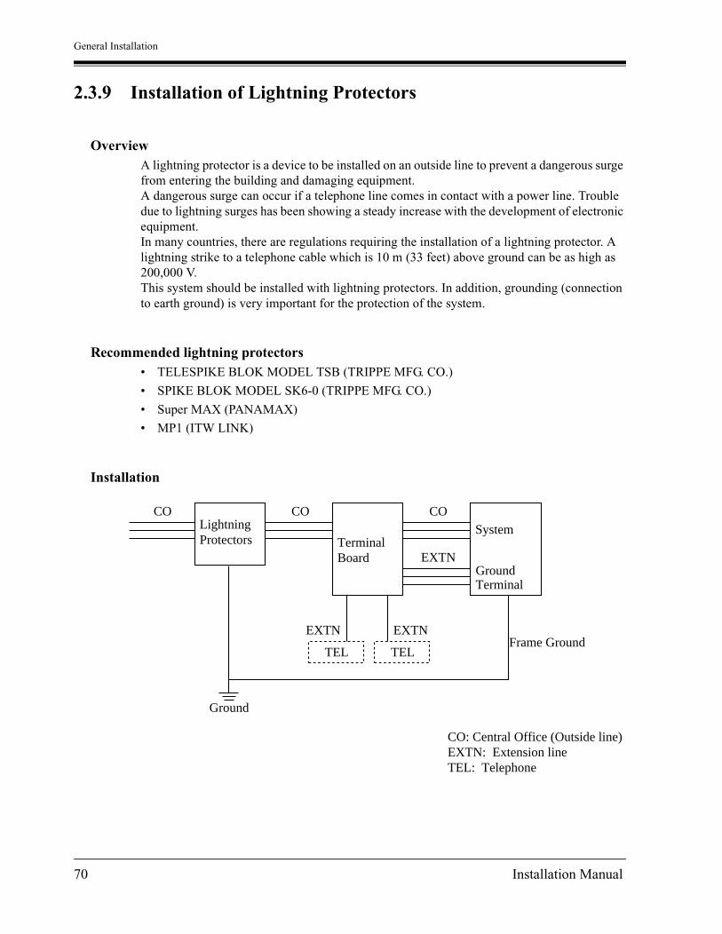
General Installation
2.3.9 Installation of Lightning Protectors
OverviewA lightning protector is a device to be installed on an outside line to prevent a dangerous surge from entering the building and damaging equipment.A dangerous surge can occur if a telephone line comes in contact with a power line. Trouble due to lightning surges has been showing a steady increase with the development of electronic equipment.In many countries, there are regulations requiring the installation of a lightning protector. A lightning strike to a telephone cable which is 10 m (33 feet) above ground can be as high as 200,000 V.This system should be installed with lightning protectors. In addition, grounding (connection to earth ground) is very important for the protection of the system.
Recommended lightning protectors• TELESPIKE BLOK MODEL TSB (TRIPPE MFG. CO.)
• SPIKE BLOK MODEL SK6-0 (TRIPPE MFG. CO.)
• Super MAX (PANAMAX)
• MP1 (ITW LINK)
Installation
TEL
Lightning Protectors
CO
Terminal Board
CO
System
Ground Terminal
CO
EXTN
EXTN
Ground
EXTN
TELFrame Ground
CO: Central Office (Outside line)EXTN: Extension lineTEL: Telephone
70 Installation Manual
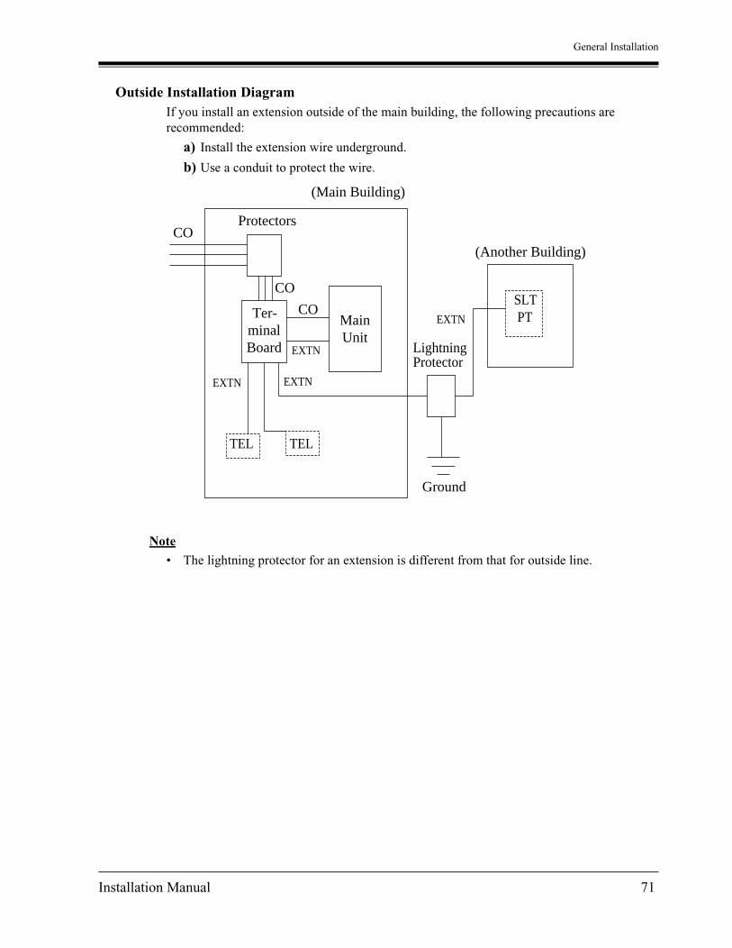
General Installation
Outside Installation DiagramIf you install an extension outside of the main building, the following precautions are recommended:
a) Install the extension wire underground.
b) Use a conduit to protect the wire.
Note
• The lightning protector for an extension is different from that for outside line.
(Main Building)
CO(Another Building)
CO
COTer-minalBoard
MainUnit
Protectors
EXTN
TELTEL
EXTN
SLTPTEXTN
LightningProtector
EXTN
Ground
Installation Manual 71
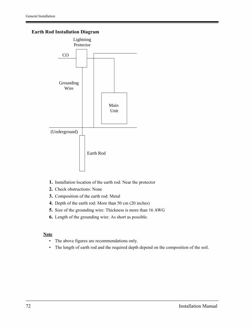
General Installation
Earth Rod Installation Diagram
1. Installation location of the earth rod: Near the protector
2. Check obstructions: None
3. Composition of the earth rod: Metal
4. Depth of the earth rod: More than 50 cm (20 inches)
5. Size of the grounding wire: Thickness is more than 16 AWG
6. Length of the grounding wire: As short as possible.
Note
• The above figures are recommendations only.
• The length of earth rod and the required depth depend on the composition of the soil.
LightningProtector
CO
Main Unit
GroundingWire
(Underground)
Earth Rod
72 Installation Manual

General Installation
2.4 Installation of Optional Cards and Unit
2.4.1 Location of Optional Cards and Units
The location of the optional cards and units is shown below.
PrecautionTo protect the printed circuit boards (P-boards) from static electricity, do not touch parts on the P-boards in the main unit and on the optional cards.
Expansion Units
KX-TD816The following expansion units can be installed to any of the two expansion areas.
Note
System Programming is required for expansion unit location. Refer to [109] Expansion Unit Type.Default:Area 1 = 4-CO Line Unit, Area 2 = 8-Station Line Unit.
Panasonic
D816
Expansionarea 2
Expansionarea 1
Expansion Unit Connectors
Remove the front cover plate(s).
8-Station Line Unit, KX-TD170or 8-Station Line Unit with SLT CID,KX-TD171
4-CO Line Unit, KX-TD180or4-DID Line Unit, KX-TD185
One extension line unit
One outside line unit or DID line unit
Remote Unit, KX-TD198
One Remote Unit
Installation Manual 73

General Installation
KX-TD1232The following expansion units can be installed to any of the three expansion areas.
Note
System Programming is required for expansion unit location. Refer to [109] Expansion Unit Type.Default: Area 1 = 4-CO Line Unit, Area 2 and 3 = 8-Station Line Unit.
Expansionarea 2
Expansionarea 3
Expansionarea 1
Expansion Unit Connectors
Remove the cover plate(s) on the front cover.
8-Station Line Unit, KX-TD170or 8-Station Line Unit with SLT CID, KX-TD171
4-CO Line Unit, KX-TD180or4-DID Line Unit, KX-TD185
Max. two extension line units
One outside line unit or DID line unitPanasonic
D1232
74 Installation Manual

General Installation
Doorphone Card for KX-TD816
Remote Card, System Inter Connection Card, DISA Card, Doorphone Card for KX-TD1232
Install Doorphone Card, KX-TD160/KX-TD161.KX-TD160 connects two doorphones and two door openers.KX-TD161 connects four doorphones and four door openers.
DoorphoneCard Connector
Front Coveris open.
REMOTE
SYSTEM INTER CONNECTION
DISA
DOORPHONE
Remote CardConnector
System InterConnectionCardConnector
DISA CardConnector
DoorphoneCard Connector
Front Cover isopen.
Install Remote Card, KX-TD196, or High Speed Remote Card, KX-TD197.This card provides data communicationsbetween the system and a remote location.
Install System Inter Connection Card, KX-TD192.This card connects two systems.
Install DISA Card, KX-TD191.This card permits access to the system fromoutside tone telephones.
Install Doorphone Card, KX-TD160/KX-TD161.KX-TD160 connects two doorphones and two door openers.KX-TD161 connects four doorphones and four door openers.
Installation Manual 75

General Installation
Caller ID Cards, PLL CardUp to two Caller ID Cards (KX-TD193) for KX-TD816, and up to three Caller ID Cards for KX-TD1232 can be installed to the initially provided Outside Line Card and 4-CO Line Unit. This card supports Caller ID services offered by the central office. The initially provided Outside Line Card is located behind the inside cover.PLL (Phase Locked Loops) Card (KX-TD112) synchronizes the system clock with the clock of the ISDN network. This card must be installed to the CPU Board before the ISDN Line Unit is installed.
4-CO Line Unit, KX-TD180 (inside the cabinet)Install one Caller ID Card, KX-TD193.
4CO DIGITAL SUPER HYBRID SYSTEM
KX-TD816Initial Outside Line CardInstall one Caller IDCard, KX-TD193.
KX-TD1232Initial Outside Line CardInstall up to two Caller IDCards, KX-TD193.
Inside cover
CPU Board Install PLL Card,KX-TD112.
Inside cover
CPU Board Install PLL Card,KX-TD112.
76 Installation Manual

General Installation
SLT Message Waiting Lamp Adaptor UnitOne SLT Message Waiting Lamp Adaptor Unit (KX-TD194) for KX-TD816, and up to two SLT Message Waiting Lamp Adaptor Units for KX-TD1232 can be installed. This card supports the Message Waiting feature for a single line telephone with a message waiting lamp. One adaptor supports 16 extensions.
Connection Example
Note
Do not connect more than four units with DC connection cables.
Panasonic
D816DIGITAL SUPER HYBRID SYSTEM
D1232DIGITAL SUPER HYBRID SYSTEM
Panasonic
D1232DIGITAL SUPER HYBRID SYSTEM
PanasonicPanasonic
KX-TD194
KX-TD194 KX-TD194 KX-TD194
To AC outlet
From a KX-TD1232 or KX-TD816
Notice
To stations
16 Extensions
KX-TD816
To AC outlet To AC outlet
KX-TD1232 System Connection KX-TD1232
(16-T / R, 1-D1/D2)
DC connection cables
<If each unit is connected to an AC outlet, these cables are not nessesary.>
Installation Manual 77

General Installation
2.4.2 4-CO Line Unit Connection
To add four outside lines (outside lines 5 through 8 for KX-TD816, and outside lines 9 through 12 for KX-TD1232), use the optional 4-CO Line Unit (KX-TD180). This unit can be installed to any of the expansion unit areas provided on the front of the main unit. For outside line expansion unit installation, see 2.4.6 Installing Expansion Unit.
Note
• System Programming is required for card location identification.
• If you intend to attach a Caller ID Card to the 4-CO Line Unit, attach the Caller ID Card before outside line connection. See 2.4.8 Caller ID Card Installation.
Programming Guide Reference[109] Expansion Unit Type
Features Guide ReferenceModule Expansion
78 Installation Manual

General Installation
2.4.3 8-Station Line Unit Connection
To add eight extensions (jack numbers 9 through 16 for KX-TD816, and jack numbers 17 through 24 or 25 through 32 for KX-TD1232), use the optional 8-Station Line Unit (KX-TD170). To add 16 extensions for KX-TD1232 (jack numbers 17 through 32), use two 8-Station Line Units.This unit can be installed to any of the expansion unit areas provided on the front of the main unit.For extension expansion unit installation, see 2.4.6 Installing Expansion Unit.
Note
System Programming is required for card location identification.
Programming Guide Reference[109] Expansion Unit Type
Features Guide ReferenceModule Expansion
Installation Manual 79

General Installation
2.4.4 8-Station Line Unit with SLT CID Connection
The optional 8-Station Line Unit with SLT CID (KX-TD171) adds eight extensions (jack numbers 9 through 16 for the KX-TD816, and jack numbers 17 through 24 or 25 through 32 for the KX-TD1232) in which either one of two ports enables the Caller ID feature for display single line telephone users.To add 16 extensions, including 2 extensions with SLT Caller ID feature, for the KX-TD1232 (jack numbers 17 through 32), use two Extension Cards with SLT CID.This unit can be installed to any of the expansion unit areas provided on the front of the main unit.For installation, see 2.4.6 Installing Expansion Unit.
Note
System Programming is required for card location identification.
Programming Guide Reference[109] Expansion Unit Type
Features Guide ReferenceModule Expansion
80 Installation Manual

General Installation
2.4.5 4-DID Line Unit Connection
To add four DID lines, use the optional 4-DID Line Unit (KX-TD185). This unit can be installed in any of the expansion areas provided on the front of the main unit. For installation, see 2.4.6 Installing Expansion Unit.
Note
System Programming is required for card location identification.
Programming Guide Reference[109] Expansion Unit Type
Features Guide ReferenceModule Expansion
Installation Manual 81

General Installation
2.4.6 Installing Expansion Unit
The following procedures can be used to install the optional expansion units.The following steps 1 through 5 and 7 through 10 are the same for all expansion units. Step 6 is different for each unit.The KX-TD1232 is illustrated as the main unit.
1. Loosen the two screws on the cover plate. Insert fingers into the slits to remove the cover plate.
Note
Any of the cover plates can be removed, as needed.
2. Connect the cabinet cord to the connector in the main unit firmly.
SlitSlit
D1232DIGITAL SUPER HYBRID SYSTEM
Panasonic
Panasonic
D1232DIGITAL SUPER HYBRID SYSTEM
82 Installation Manual

General Installation
3. Hook the cabinet on the main unit and slide the cabinet to the left until it is secured.
4. Loosen the outside screw and slide the cover to the right.
5. Secure the inside screw (included) to fix the cabinet to the main unit.
Note
Be sure to fix the inside screw to the main unit, or the unit may not work properly.
Panasonic
D1232DEGITAL SUPER HYBRID SYSTEM
Panasonic
D1232DIGITAL SUPER HYBRID SYSTEM
Outside screw
Inside screw
Panasonic
D1232DIGITAL SUPER HYBRID SYSTEM
Installation Manual 83

General Installation
6. (If a option is to be installed)
If a KX-TD180 / KX-TD185 is to be installed; (for KX-TD1232)
Insert the modular plugs of the telephone line cords (4-conductor wiring) into the modular jacks on the unit.
Note
• * For details, refer to 2.5.1 Auxiliary Connection for Power Failure Transfer.
• DID lines of the KX-TD185 are polarity sensitive.
Jack for PowerFailure Transfer*
To Terminal Board or ModularJacks from the Central Office
Panasonic
4CO DIGITAL SUPER HYBRID SYSTEM
PFT ports
2CO w/PFT
2CO
R: RingT: Tip
T2 R1 T1 R2
View of TEL Jack (Outside Line)
(T1/R1) (T2/R2)Outside Line 9, Outside Line 10
Outside Line 11, Outside Line 12
84 Installation Manual

General Installation
If a KX-TD170 / KX-TD171 is to be installed; (for KX-TD1232)
Insert the connector into the jack.
Note
• * For details, refer to 2.5.1 Auxiliary Connection for Power Failure Transfer.
• For cable pin numbers to be connected, see "Pin Number Chart" in 2.3.2 Extension Connection.
• For fixing the connector, see "Amphenol 57JE Type (screw-attach-type 50-pin connector) Connection for KX-TD170 / KX-TD171" in 2.4.6 Installing Expansion Unit.
Jack for PowerFailure Transfer*
To extensions(TD816 : Jacks 9 – 16,TD1232: Jacks 17 – 24 or 25 – 32)
Panasonic
8EXT DIGITAL SUPER HYBRID SYSTEM
PFT ports
8EXT
25
50
1
26
Connector type50-pin (Amphenol 57JEseries or the equivalent)
Installation Manual 85

General Installation
7. Tie all of the cords into a bundle. If other cords are exposed in the upper cabinets, tie them also.
8. Close the cabinet cover and secure the outside screw.
9. Cover the cords with the cord holder (included).
10.Fix the cords to the wall as shown so that the front cover can be opened.
Cord holder
D1232DIGITAL SUPER HYBRID SYSTEM
Panasonic
D1232DIGITAL SUPER HYBRID SYSTEM
Panasonic
86 Installation Manual

General Installation
Note
• If you attach the Caller ID Card (KX-TD193) to the 4-CO Line Unit (KX-TD180), attach it before installing the 4-CO Line Unit to the main unit. For installation, Refer to 2.4.8 Caller ID Card Installation.
• If two expansion units are installed, cut the cabinet cover(s) on the lower cabinet(s) to allow the cords from upper cabinet to go down through the cabinet cover(s). To protect the cords, smooth the cut edges.
Cut here
Installation Manual 87

General Installation
Amphenol 57JE Type (screw-attach-type 50-pin connector) Connection for KX-TD170 / KX-TD171
To fix the Amphenol 57JE type (screw-attach type 50-pin connector) to the 8-Station Line Unit or the 8-Station Line Unit with SLT CID, follow the procedure below.
1. The 50-pin connector (Jack) on the Expansion Unit has two hook-pins. Remove the upper hook-pin, and take out the screw.
Note
When installing a connector like the type shown below, unscrew the lower hook-pin also. Then drive both accessory screws.
8EXTDIGITAL SUPER HYBRID SYSTEM
Screw
50-pinconnector
Hook-pins
Accessory screw
Amphenol 57JE type
Accessoryscrew
50-pinconnector
88 Installation Manual

General Installation
2. To attach the Amphenol 57JE type (Plug) to the connector, drive the accessory screw into the upper part.Fasten the accessory wire tie around the lower hook-pin and the Amphenol 57JE type, as shown.
Accessory screw
Amphenol 57JE type
Accessory wire tie
57JE type
Hook-pin
Accessorywire tie
Installation Manual 89

General Installation
2.4.7 DISA Card and Remote Card / Unit Installation
The DISA Card (KX-TD191), Remote Card (KX-TD196), High Speed Remote Card (KX-TD197) and Remote Unit (KX-TD198) can be installed as follows.
Note
If you use the KX-TD170 with the KX-TD198, you must use the KX-TD170 which has suffix 'C' or later.The former KX-TD170 dose not work properly with KX-TD198.This is available for the KX-TD816 only.Please see the back of the unit and check suffix.
How to distinguish suffix
Main Unit For DISA feature For remote access
KX-TD816 KX-TD198
KX-TD1232 KX-TD191 KX-TD196, KX-TD197
Serial No. LABEL
Suffix UNIT No.
C
90 Installation Manual

General Installation
KX-TD816
Installing the Remote Unit (KX-TD198)1. Loose the two screws on the cover plate. Insert your fingers into the slits to remove the
cover plate.
Note
There are two cover plates. Any of them can be removed, as needed.
2. Connect the cabinet cord to the connector in the main unit firmly.
3. Hook the cabinet onto the main unit and slide the cabinet to the left until it is secured.
D816DIGITAL SUPER HYBRID SYSTEM
Panasonic
SlitSlit
Panasonic
D816DIGITAL SUPER HYBRID SYSTEM
Panasonic
Panasonic
D816DIGITAL SUPER HYBRID SYSTEM
Installation Manual 91

General Installation
Attaching another line expansion unit to the Remote Unit (KX-TD198) and install them to the system.
1. Remove the front cover of the Remote Unit. Set the MODE switch to 2 only.
2. Attach the expansion unit to the Remote Unit as shown below. Be sure to connect the cabinet cords by inserting the expansion unit cabinet cord through the slot in the Remote Unit.
3. Remove the cover plate and connect the cabinet cord to the connector in the main unit firmly.
MODE1 2
Expansion unit cabinet cord
Remote unit cabinet cord
Panasonic
D816DIGITAL SUPER HYBRID SYSTEM
Panasonic
92 Installation Manual

General Installation
4. Hook the cabinets onto the main unit and slide the cabinets to the left until they are secured.
5. Loosen the outside screw of the expansion unit and slide the cover to the right.
6. Secure the inside screw (inside with the Remote Unit) to fix the cabinet to the main unit.
7. Tie all of the cords into a bundle. If other cords are exposed from the upper cabinets, tie them also.
8. Close the cabinet cover and secure the outside screw.
9. Cover the cords with the cord holder. If two cabinets are connected together and attached to the main unit, use the cord holder included with the Remote Unit.
10.Fix the cords to the wall as shown here, so that the front cover can be opened.
Panasonic
D816DIGITAL SUPER HYBRID SYSTEM
Panasonic
D816DIGITAL SUPER HYBRID SYSTEM
Outside screw
Panasonic
D816DIGITAL SUPER HYBRID SYSTEM
Inside screw
Panasonic
D816DIGITAL SUPER HYBRID SYSTEM
Panasonic
Cord holder
Installation Manual 93

General Installation
KX-TD1232
Installing the DISA Card (KX-TD191)1. Insert the upper side of the DISA Card into the two hooks on the main unit.
2. Press down the two corners of the lower side of the DISA Card.
3. Connect the cord to the DISA Card Connector.
Features Guide ReferenceDirect Inward System Access (DISA)
DISA Card
94 Installation Manual

General Installation
Installing the Remote Card (KX-TD196) or High Speed Remote Card (KX-TD197)1. Insert the upper side of the Remote Card into the two hooks on the main unit.
2. Press down the two corners of the lower side of the Remote Card.
3. Connect the cord to the Remote Card Connector.
Programming Guide Reference[107] System Password
[813] Floating Number Assignment
[814] Modem Standard
[817] KX-TD197 / KX-TD198 Baud Rate Set
Features Guide ReferenceSystem Programming and Diagnosis with Personal Computer
Installation Manual 95

General Installation
2.4.8 Caller ID Card Installation
A maximum of two Caller ID Cards (KX-TD193) can be installed to the KX-TD816, and a maximum of three Caller ID Cards can be installed to the KX-TD1232. The Caller ID Cards can be installed to the initially provided Outside Line Card and / or to an optional 4-CO Line Unit (KX-TD180), as required.The Outside Line Card of KX-TD816 can accept one Caller ID Card, and the Outside Line Card of KX-TD1232 can accept two Caller ID Cards. 4-CO Line Unit can accept one Caller ID Card.
Installing to the Initial Outside Line Card for KX-TD8161. Loosen the four screws to open the inside cover of the main unit.
Note
If any cards, units, or cords are installed to the main unit, remove them beforehand.
2. Insert the Caller ID Card to the connectors on the Outside Line Card.One card can be installed to the initial Outside Line Card.
3. Put the inside cover back on the main unit and secure the screws.
KX-TD193 CALLER ID
Outside Line Card
Caller ID Card
Inside cover
96 Installation Manual

General Installation
Installing to the Initial Outside Line Card for KX-TD12321. Loosen the eight screws to open the inside cover of the main unit.
Note
If any cards, units, or cords are installed to the main unit, remove them beforehand.
2. Insert the Caller ID Card(s) to the connectors on the Outside Line Card.Up to two cards can be installed to the initial Outside Line Card.
3. Put the inside cover back on the main unit and secure the screws.
Outside Line Card
Caller ID Card
Inside cover
KX-TD193 CALLER ID
KX-TD193 CALLER ID
Installation Manual 97

General Installation
Installing to the Optional 4-CO Line Unit The following procedure must be done before installing the 4-CO Line Unit (KX-TD180) to the main unit.
1. Loosen the five screws located at the rear of the 4-CO Line Unit.
2. Remove the back plate and take out the P-board.
3. Attach the Caller ID Card to the P-board, fitting the connectors.
4. Put the P-board back into the cabinet and fix the rear plate with the five screws.
Note
For installing the 4-CO Line Unit to the main unit, refer to 2.4.6 Installing Expansion Unit.
Programming Guide Reference[110] Caller ID Code Set
[111] Caller ID Name Set
[125] Area Code Assignment
[126] Caller ID Modification for Local Call
[127] Caller ID Modification for Long Distance Call
[406] Caller ID Assignment
Features Guide ReferenceCaller ID
Caller ID Card
back plate
P-board
4CO DIGITAL SUPER HYBRID SYSTEM
KX-TD193 CALLER ID
98 Installation Manual

General Installation
2.4.9 Doorphone and Door Opener Connection
To connect up to two doorphones (KX-T30865) and up to two door openers (user-supplied), a Doorphone Card (KX-TD160) is required.To connect up to four doorphones (KX-T30865) and up to four door openers (user-supplied), a Doorphone Card (KX-TD161) is required.
Installing the Doorphone1. Loosen the screw to separate the doorphone into two halves.
2. Install the base cover to the wall with two screws.
Note
Two kinds of screws are included. Please choose the appropriate one depending on your wall type:
3. Connect the wires to the screws located in the front cover.
4. Secure both halves together and re-install the screw.
screw
Panasonic
Type 1: When the doorphoneplate has been fixed tothe wall.
When you wish toinstall the doorphonedirectly to the wall.
Type 2:
To the terminal box (See"Wiring of the Doorphone".)
Installation Manual 99

General Installation
Doorphone Card Installation (for KX-TD160)1. Connect a 4-conductor modular connector to the Doorphone Card Cabinet, and pass the
cord through the groove in the cabinet.
2. Attach the Doorphone Card Cabinet to the main unit and press down.
3. Connect the cord to the Doorphone Card Connector.
KX-TD1232 KX-TD816
To Terminal BoxInstallation
100 Installation Manual

General Installation
Doorphone Card Installation (for KX-TD161)1. Connect two 4-conductor modular connectors to the Doorphone Card Cabinet, and pass the
cords through the grooves in the cabinet.
2. Attach the Doorphone Card Cabinet to the main unit and press down.
3. Connect the cords to the Doorphone Card Connector.
KX-TD1232 KX-TD816
To Terminal BoxInstallation
Installation Manual 101

General Installation
Wiring of the Doorphone (for KX-TD160)1. Connect the Doorphone Card to the terminal box using a 4-conductor modular connector.
2. Connect the wires of doorphone 1 to the red and green screws of the terminal box.
3. Connect the wires of doorphone 2 to the yellow and black screws of the terminal box.
KX-TD816
KX-TD1232
4-conductor wiringis required.
4-conductor wiringis required.
Doorphone 1(KX-T30865)
Doorphone 2(KX-T30865)
Doorphone 1(KX-T30865)
Doorphone 2(KX-T30865)
Panasonic Panasonic
Yellow
Red
Black
Green
Yellow
Red
Black
Green
Terminal Box
Terminal Box
Panasonic Panasonic
102 Installation Manual
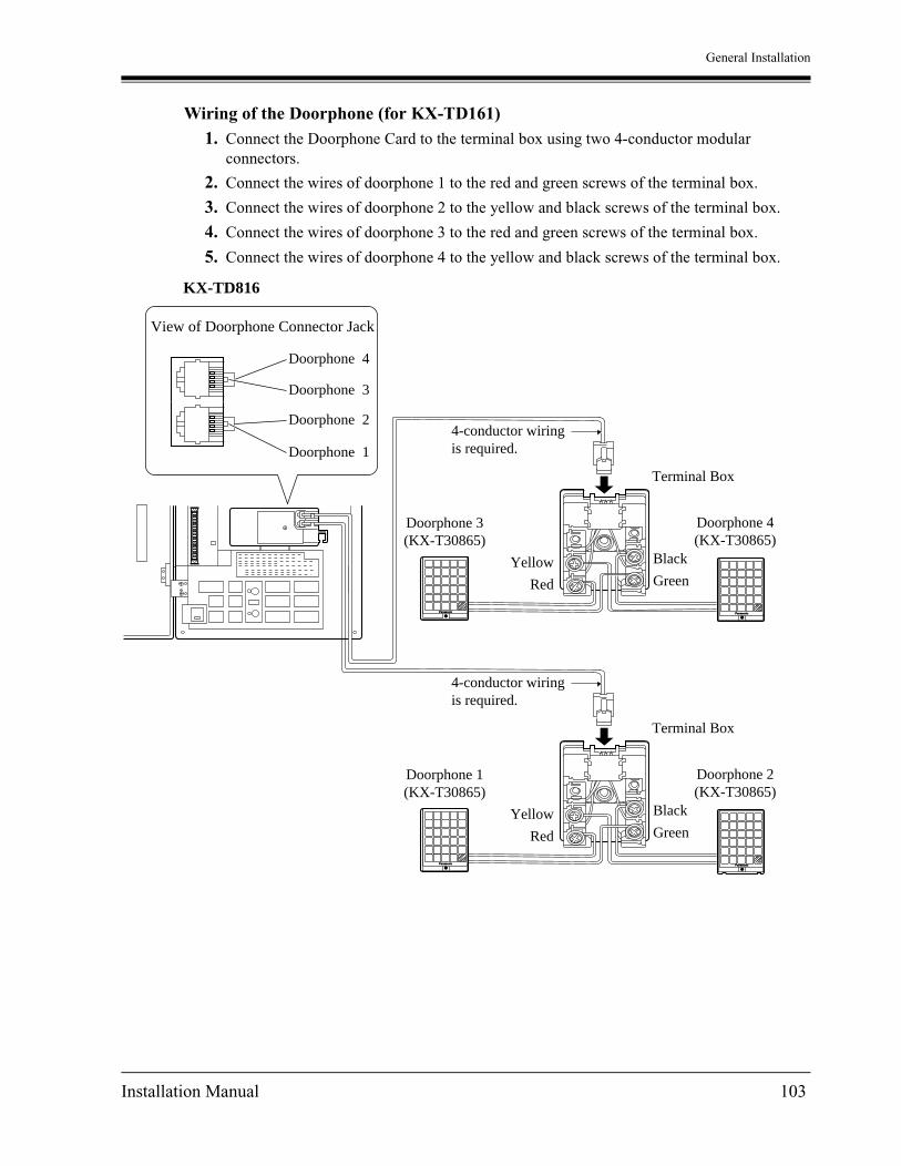
General Installation
Wiring of the Doorphone (for KX-TD161)1. Connect the Doorphone Card to the terminal box using two 4-conductor modular
connectors.
2. Connect the wires of doorphone 1 to the red and green screws of the terminal box.
3. Connect the wires of doorphone 2 to the yellow and black screws of the terminal box.
4. Connect the wires of doorphone 3 to the red and green screws of the terminal box.
5. Connect the wires of doorphone 4 to the yellow and black screws of the terminal box.
4-conductor wiringis required.
Doorphone 3(KX-T30865)
Doorphone 4(KX-T30865)
Yellow
Red
Black
Green
Terminal Box
Panasonic Panasonic
4-conductor wiringis required.
Doorphone 1(KX-T30865)
Doorphone 2(KX-T30865)
Yellow
Red
Black
Green
Terminal Box
Panasonic Panasonic
View of Doorphone Connector Jack
Doorphone 1
Doorphone 3
Doorphone 2
Doorphone 4
KX-TD816
Installation Manual 103

General Installation
4-conductor wiringis required.
Doorphone 3(KX-T30865)
Doorphone 4(KX-T30865)
Yellow
Red
Black
Green
Terminal Box
Panasonic Panasonic
4-conductor wiringis required.
Doorphone 1(KX-T30865)
Doorphone 2(KX-T30865)
Yellow
Red
Black
Green
Terminal Box
Panasonic Panasonic
View of Doorphone Connector Jack
Doorphone 1
Doorphone 3
Doorphone 2
Doorphone 4
KX-TD1232
104 Installation Manual

General Installation
Connecting Door Openers (for KX-TD160)1. Loosen the screw to remove the cover.
2. Loosen the screws on the terminal strip.
Installation Manual 105

General Installation
3. Insert the wires coming from the door openers into holes and tighten the screws.Pass all the wires through the Holder.
Note
• The KX-TD1232 is illustrated as the main unit.
• Set the door opener paired with the doorphone.
• For wiring, UL 1015, AWG 22 twisted wire or the equivalent is recommended.
• The wire should be between 1.2 and 2.4 mm (3/64 and 3/32 inch) in diameter including the coating.
To dooropener 2
Holder
To dooropener 1
D=1.2-2.4 mm (3/64-3/32 inch)
106 Installation Manual

General Installation
Connecting Door Openers (for KX-TD161)1. Loosen the screw to remove the cover.
2. Loosen the screws on the terminal strip.
Installation Manual 107

General Installation
3. Insert the wires coming from the door openers into holes and tighten the screws.Pass all the wires through the Holder.
Note
• The KX-TD1232 is illustrated as the main unit.
• Set the door opener paired with the doorphone.
• For wiring, UL 1015, AWG 22 twisted wire or the equivalent is recommended.
• The wire should be between 1.2 and 2.4 mm (3/64 and 3/32 inch) in diameter including the coating.
To door opener 3
To door opener 4
Holder
To door opener 2
To door opener 1
D=1.2-2.4 mm (3/64-3/32 inch)
108 Installation Manual
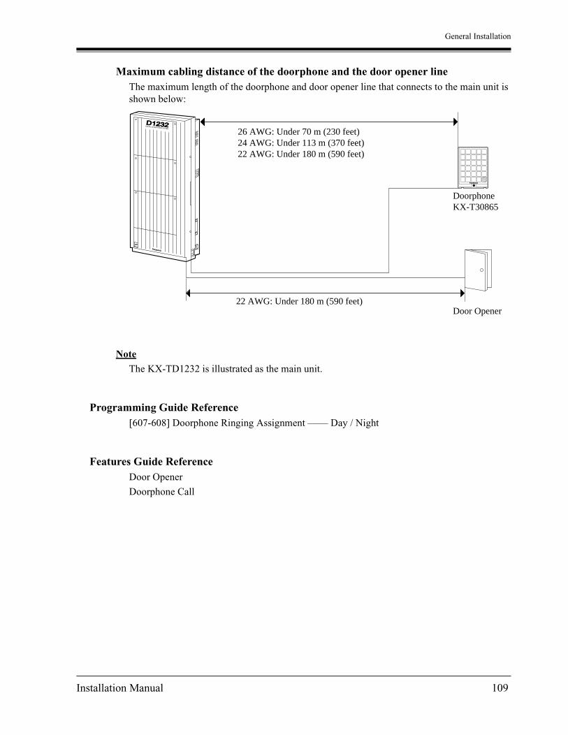
General Installation
Maximum cabling distance of the doorphone and the door opener lineThe maximum length of the doorphone and door opener line that connects to the main unit is shown below:
Note
The KX-TD1232 is illustrated as the main unit.
Programming Guide Reference[607-608] Doorphone Ringing Assignment —— Day / Night
Features Guide ReferenceDoor Opener
Doorphone Call
26 AWG: Under 70 m (230 feet)24 AWG: Under 113 m (370 feet)22 AWG: Under 180 m (590 feet)
DoorphoneKX-T30865
Door Opener22 AWG: Under 180 m (590 feet)
D1232DIGITAL SUPER HYBRID SYSTEM
Panasonic
Panasonic
Installation Manual 109
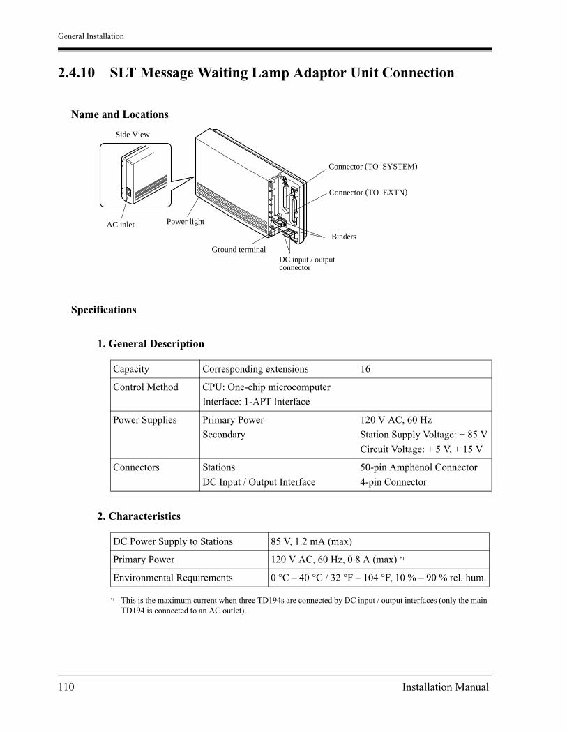
General Installation
2.4.10 SLT Message Waiting Lamp Adaptor Unit Connection
Name and Locations
Specifications
1. General Description
2. Characteristics
Capacity Corresponding extensions 16
Control Method CPU: One-chip microcomputer
Interface: 1-APT Interface
Power Supplies Primary Power
Secondary
120 V AC, 60 Hz
Station Supply Voltage: + 85 V
Circuit Voltage: + 5 V, + 15 V
Connectors Stations
DC Input / Output Interface
50-pin Amphenol Connector
4-pin Connector
DC Power Supply to Stations 85 V, 1.2 mA (max)
Primary Power 120 V AC, 60 Hz, 0.8 A (max) *1
*1 This is the maximum current when three TD194s are connected by DC input / output interfaces (only the main TD194 is connected to an AC outlet).
Environmental Requirements 0 °C – 40 °C / 32 °F – 104 °F, 10 % – 90 % rel. hum.
Side View
AC inlet Power light
Ground terminal
Binders
DC input / outputconnector
Connector (TO SYSTEM)
Connector (TO EXTN)
110 Installation Manual

General Installation
WARNINGTHIS UNIT MAY ONLY BE INSTALLED AND SERVICED BY QUALIFIED SERVICE PERSONNEL.
Wall MountingThis unit can be mounted to a wall. Refer to 2.2.3 Wall Mounting
Opening the front cover1. Loosen the screw.
2. Slide the cover while pressing the mark.
Note
The screw cannot be removed from the unit.
Template
Template
or
Screw
Installation Manual 111

General Installation
Frame Ground Connection
IMPORTANTConnect the system frame to the ground.
1. Loosen the screw.
2. Insert the grounding wire.
3. Tighten the screw.
4. Connect the grounding wire to the ground.
In most of the continental United States, the ground provided by the "Third wire ground" at the commercial power outlet will be satisfactory. However, in a small percentage of cases this ground may be installed incorrectly. Therefore, the following test procedure should be performed.
Test Procedure1. Obtain a suitable voltmeter and set it for a possible reading of up to 250 VAC.
2. Connect the meter probes between the two main AC voltage points on the wall outlet. The reading should be 108 – 132 VAC.
3. Move one of the meter probes to the 3rd prong terminal (GND).Either the same reading or a reading of 0 V should be obtained.
4. If a reading of 0 V at one terminal and a reading of 108 – 132 VAC at the other terminal is not obtained, the outlet is not properly grounded. This should be corrected by a qualified electrician (per article 250 of the National Electrical Code).
5. If a reading of 0 V at one terminal and a reading of 108 – 132 VAC at the other terminal is obtained, then set the meter to the "OHMS / RX1" scale, place one probe at the GND Terminal and the other probe at the terminal which gave a reading of 0 V. A reading of less than 1 ohm should be obtained. If the reading is not obtained, the outlet is not adequately grounded. See a qualified electrician.
To groundScrew
112 Installation Manual

General Installation
Inserting the Connector1. Insert the two 50-pin connectors to the jacks as shown below.
The connector "TO SYSTEM" should be connected to the cable which is connected to the KX-TD816 / KX-TD1232.Also, the connector "TO EXTN" should be connected to the cable which is connected to the extensions.
2. Insert the cables through the binders.
3. If two units are connected with the DC IN / OUT, insert the 4-pin connectors to the jacks as shown on the next page.
25
50
1
26
Connector type50-pin (Amphenol 57JEseries or the equivalent)
Connector (TO SYSTEM)
Connector (TO EXTN)
To ExtensionsTo System (TD816 / TD1232)
Binders
Installation Manual 113

General Installation
DC IN / OUT
To anotherKX-TD194 (See "SLT Message Waiting Lamp Adaptor Unit Connection", "Location of Optional Cards and Units" in this section for a connection example.)
Side View
114 Installation Manual

General Installation
Cable Pins to Be Connected
CONN.PIN
To System Connector
(CN1)
To Extension Connector
(CN2)
261
APTDATA
D1D2
EXTN. 1TR
272
EXTN. 1TR
EXTN. 2TR
283
EXTN. 2TR
EXTN. 3TR
294
EXTN. 3TR
EXTN. 4TR
305
EXTN. 4TR
EXTN. 5TR
316
EXTN. 5TR
EXTN. 6TR
327
EXTN. 6TR
EXTN. 7TR
338
EXTN. 7TR
EXTN. 8TR
349
EXTN. 8TR
EXTN. 9TR
3510
EXTN. 9TR
EXTN. 10TR
3611
EXTN. 10TR
EXTN. 11TR
3712
EXTN. 11TR
EXTN. 12TR
3813
EXTN. 12TR
EXTN. 13TR
3914
EXTN. 13TR
EXTN. 14TR
4015
EXTN. 14TR
EXTN. 15TR
4116
EXTN. 15TR
EXTN. 16TR
4217
EXTN. 16TR
Installation Manual 115
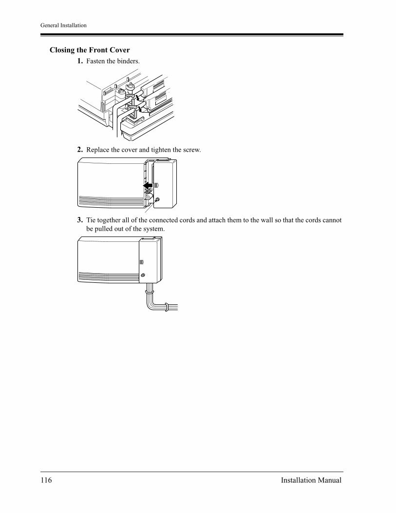
General Installation
Closing the Front Cover1. Fasten the binders.
2. Replace the cover and tighten the screw.
3. Tie together all of the connected cords and attach them to the wall so that the cords cannot be pulled out of the system.
116 Installation Manual

General Installation
Starting the unitPlug the AC cord into the system AC inlet and an AC outlet.Avoid sharing the AC outlet of this system with other office equipment. Use a dedicated AC outlet only.
CAUTIONThe power supply cord is used as the main disconnect device. Ensure that the socket-outlet is located / installed near the equipment and is easily accessible.
AC Surge Protecter
134 cm (52 3/4 inches)
Installation Manual 117

General Installation
2.4.11 System Connection*1
To connect two main units, use the optional System Inter Connection Cards (two) and the Connection Cable (included in the cards).
1. Insert the upper side of the System Inter Connection Card into two hooks on the main unit (Master System).
2. Press down the two corners of the lower side of the System Inter Connection Card.
3. Connect the cord to the System Inter Connection Card connector.
4. Open the latch on the card.
5. Repeat steps 1 through 4 for the Slave System, using the other card.
6. Insert one Connection Cable end into the Master System and insert the other end into the Slave System.
*1 Available for the KX-TD1232 only.
System Inter Connection Card
KX-TD192 SYSTEM INTER CONNECTION
System Inter Connection Card
118 Installation Manual

General Installation
7. Close the latches on both systems.
8. Open the ROM Cover in the Slave System and set the Master / Slave Switch on the CPU Card to "Slave" position.
9. Turn the power on.
Note
• System Connection is completed about three minutes after the power is turned on. To confirm System Connection completion, try to call a Slave System extension from a Master System extension.
• To turn the power on for the first time, refer to Section 2.6 "Starting the System for the First Time".
• The master and slave must have the same version software. Otherwise, System Connection will not work properly.
• When you install an ISDN Line Unit, you should install it to the Master System first and then the Slave System. If only installed to the Slave System, noise may occur.
Connection Cable
REMOTE
DISA
MASTER
SLAVE
Installation Manual 119

General Installation
Programming Guide ReferenceNo programming required.
Features Guide ReferenceSystem Connection
120 Installation Manual

General Installation
2.5 Auxiliary Connection for Power Failure Transfer
2.5.1 Auxiliary Connection for Power Failure Transfer
Power Failure Transfer connects specific single line telephones to selected outside lines in the event of system power failure, as follows:
KX-TD816Outside Line 1 — Extension (T, R) Jack 1 / Outside Line 2 — Extension (T, R) Jack 2 /Outside Line 5 — Extension (T, R) Jack 9 /Outside Line 6 — Extension (T, R) Jack 10 Connections of outside lines 1, 2 and the respective extensions require no auxiliary connection. Outside lines 5 and 6 require auxiliary connection to implement this feature.
KX-TD1232Outside Line 1 — Extension (T, R) Jack 1 / Outside Line 2 — Extension (T, R) Jack 2 / Outside Line 3 — Extension (T, R) Jack 9 / Outside Line 4 — Extension (T, R) Jack 10 /Outside Line 9 — Extension (T, R) Jack 17 /Outside Line 10 — Extension (T, R) Jack 18Connections of outside lines 1 through 4 and the respective extensions require no auxiliary connection. Outside lines 9 and 10 require auxiliary connection to implement this feature.
Insert the modular plugs of connection cords (4-conductor wiring) to the modular jacks of 4-CO Line Unit and 8-Station Line Unit 1.(In the case of KX-TD816, one 8-Station Line Unit is available.)
Panasonic
4CO DIGITAL SUPER HYBRID SYSTEM
PFT PARTS
2CO W/PFT
2CO
8EXT DIGITAL SUPER HYBRID SYSTEM2CO
PFT ports
R: RingT: Tip
T2 R1 T1 R2
View of TEL Jack (Outside Line)
Installation Manual 121

General Installation
Note
• In the event of a power failure, system memory is protected by a factory-provided lithium battery. There is no memory loss except the memories of Camp-on, Saved Number Redial, Last Number Redial, Call Park and Message Waiting.
• The system changes the current connection to this connection automatically when the power supply stops.
• The KX-TD1232 is illustrated as the main unit, and the KX-TD170 and KX-TD180 are illustrated as the expansion units.
Features Guide ReferencePower Failure Transfer
122 Installation Manual
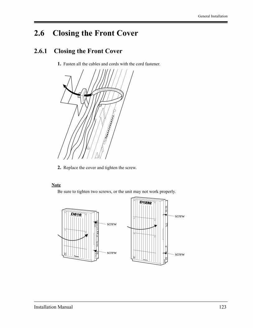
General Installation
2.6 Closing the Front Cover
2.6.1 Closing the Front Cover
1. Fasten all the cables and cords with the cord fastener.
2. Replace the cover and tighten the screw.
Note
Be sure to tighten two screws, or the unit may not work properly.
Panasonic
D816DIGITAL SUPER HYBRID SYSTEM
D1232DIGITAL SUPER HYBRID SYSTEM
Panasonic
screw
screw
screw
screw
Installation Manual 123

General Installation
3. Tie together all of the connected cords and attach them to the wall so that the cords cannot be pulled out of the main unit.
D1232DIGITAL SUPER HYBRID SYSTEM
Panasonic
D816DIGITAL SUPER HYBRID SYSTEM
124 Installation Manual

General Installation
2.7 Starting the System for the First Time
2.7.1 Starting the System for the First Time
1. Set the Power Switch to the "OFF" position.
2. Set the System Clear Switch to the "CLEAR" position.
3. Plug the AC power cord into the system and an AC outlet.
4. Turn the Power Switch on.
5. Press the Reset Button with a pointed tool. (The power indicator will flash.)
6. Slide the System Clear Switch to the "NORMAL" position while the power indicator is flashing (within approximately 10 seconds).
The system will be initialized with default values. The system will also check the outside lines, extensions, and optional cards and units.
KX-TD816
D816DIGITAL SUPER HYBRID SYSTEM
Panasonic
RESET NORMAL CLEAR
SYSTEM CLEAR
Power Indicator
Reset Button
System Clear Switch
To AC Outlet
Power Switch
Installation Manual 125

General Installation
KX-TD1232
Notice
• After pressing the Reset Button, slide the System Clear Switch to the "NORMAL" position at step 6 while the power indicator is flashing (within approximately 10 seconds). Otherwise, the system will not start up with the default values.
CAUTIONThe power socket wall outlet should be located near this equipment and be easily accessible.
Once you start up the system and you turn the power off, do not perform the above procedure to start the system again. Otherwise, your programmed data will be cleared. To start the system, just turn the Power Switch on.
The power outlet should be located near this equipment and easily accessible.
SYSTEMCLEAR
CLEAR
NORMAL
RESET
Power Indicator
System ClearSwitch
Reset Button
To AC OutletPowerSwitch
126 Installation Manual

General Installation
2.8 System Restart
2.8.1 System Restart
After starting the system, if the system does not operate properly, restart the system.Before restarting the system, try the system feature again to confirm whether there definitely is a problem or not.System Restart causes the following:
a) Camp-on is cleared.
b) Calls on Hold are terminated.
c) Calls on Exclusive Hold are terminated.
d) Calls in progress are terminated.
e) Call Park is cleared.
Other data is not cleared by System Restart.
1. Make sure that the System Clear Switch is set to the "NORMAL" position.
2. Press the Reset Button with a pointed tool.
Notice
After pressing the Reset Button, if you notice that the System Clear Switch is set to the "CLEAR" position, never slide the System Clear Switch to the "NORMAL" position within 20 seconds. Otherwise, all the system programming data are reset to default values (Refer to 2.9.1 System Data Clear). Wait at least 30 seconds, then slide to the "NORMAL" position. Then the system will work as before.
If the system still does not operate properly, please see 5.1.4 Using the Reset Button.
Installation Manual 127
General Installation
2.9 System Data Clear
2.9.1 System Data Clear
After storing or changing the system programming data, it is possible to clear your programming data stored in the system, if required. The system will restart with the default setting.
1. Slide the System Clear Switch to the "CLEAR" position.
2. Press the Reset Button with a pointed tool.
3. Return the System Clear Switch to the "NORMAL" position while the power indicator is flashing (within approximately 10 seconds).
Notice
After pressing the Reset Button, return the System Clear Switch to the "NORMAL" position in step 3 while the power indicator is flashing (within approximately 10 seconds). Otherwise, the system will not clear.
128 Installation Manual

ISDN Installation
Section 3
ISDN Installation
Installation Manual 129

ISDN Installation
3.1 ISDN Network Outline
3.1.1 Overview
To use the ISDN Line Service, the following unit can be installed to the KX-TD816 and KX-TD1232.
2-ISDN U-point Line Unit (KX-TD382)4-ISDN U-point Line Unit (KX-TD384)6-ISDN U-point Line Unit (KX-TD386)4-ISDN S / T-point Line Unit (KX-TD284)Primary Rate Interface ISDN Expansion Unit (KX-TD290) [KX-TD1232 Master only]
These units add ISDN U-point or S / T-point lines.These units can be installed in any of the expansion areas provided on the front of the main unit.The KX-TD290 adds one Primary Rate Interface (PRI) ISDN line. One PRI ISDN line adds 23 outside lines (outside lines 25 through 47) to the system. This unit can only be installed to the KX-TD1232 Master system.When the KX-TD290 is installed to the system, the maximum number of available outside lines is limited to 31. In the case of System Connection, the basic and extended outside line in the Slave system cannot be used.
Notice
• System Programming is required for card location identification. It is not possible to connect this unit only to the slave system.
• The PLL (Phase Locked Loops) Card (KX-TD112) must be installed to the system before the ISDN Line Unit is installed. This card is used to synchronize the system clock with the clock of the ISDN network.
• In the System Connection of the KX-TD1232, the PLL Card can be installed to the only master system.
• If you use the KX-TD170 with the KX-TD290, you must use the KX-TD170 which has suffix 'C' or later.The former KX-TD170 does not work properly with KX-TD290.Please see the back of the unit and check suffix.
130 Installation Manual

ISDN Installation
How to distinguish suffix
• System Programming is required for card location identification.
Programming Guide References[109] Expansion Unit Type
Features Guide ReferencesModule Expansion
The compatibility between KX-TD290 and KX-TD170
Master System Slave System
With KX-TD290 Suffix 'C' or later Don't care. *1
*1 KX-TD290 can not be installed in slave system.
Without KX-TD290 Don't care. Don't care. *1
Serial No. LABEL
Suffix UNIT No.
C
Installation Manual 131

ISDN Installation
3.2 ISDN Line Connection
3.2.1 Location of the Units
KX-TD816 One ISDN Line Unit (KX-TD382, KX-TD384, KX-TD386 or KX-TD284) can be installed to any expansion area.
Note
• System Programming is required for expansion unit location. <SYS PRG [109]>Default : Area 1 = 4-CO Line Unit
Area 2 = 8-Station Line Unit
• Either one KX-TD382, one KX-TD384, one KX-TD386 or one KX-TD284 can be installed in a system.
• For unit combinations, refer to 1.4.2 Expansion Unit Combination.
Panasonic
D816
Expansionarea 2
Expansionarea 1
Expansion Unit Connectors
Remove the front cover plate(s).
2-ISDN S0 Line Unit, KX-TD382:or4-ISDN S0 Line Unit, KX-TD384:or6-ISDN S0 Line Unit, KX-TD386:or4-ISDN S0 Line Unit, KX-TD284:
One ISDN line unit
132 Installation Manual
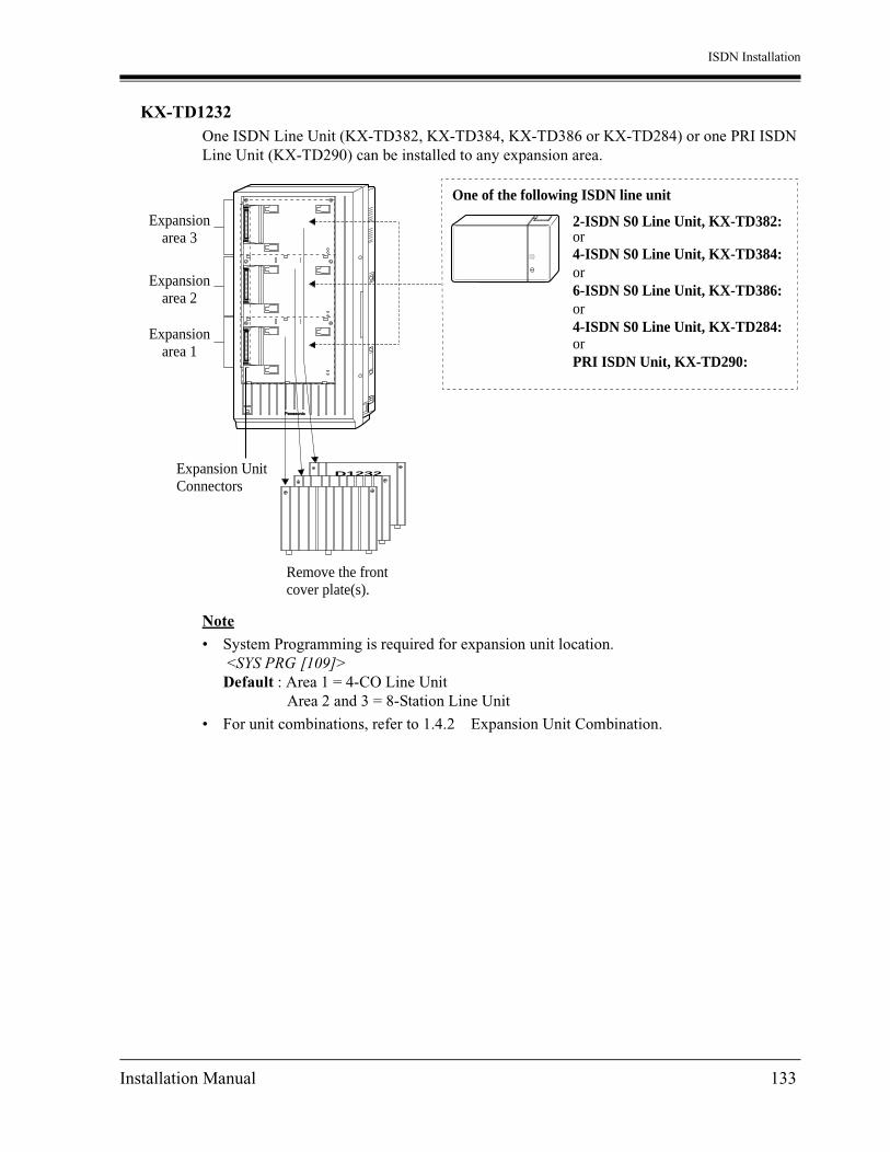
ISDN Installation
KX-TD1232 One ISDN Line Unit (KX-TD382, KX-TD384, KX-TD386 or KX-TD284) or one PRI ISDN Line Unit (KX-TD290) can be installed to any expansion area.
Note
• System Programming is required for expansion unit location. <SYS PRG [109]>Default : Area 1 = 4-CO Line Unit
Area 2 and 3 = 8-Station Line Unit
• For unit combinations, refer to 1.4.2 Expansion Unit Combination.
Expansionarea 2
Expansionarea 3
Expansionarea 1
Expansion Unit Connectors
Remove the front cover plate(s).
2-ISDN S0 Line Unit, KX-TD382:or4-ISDN S0 Line Unit, KX-TD384:or6-ISDN S0 Line Unit, KX-TD386:or4-ISDN S0 Line Unit, KX-TD284:orPRI ISDN Unit, KX-TD290:
One of the following ISDN line unit
Panasonic
D1232
Installation Manual 133

ISDN Installation
3.2.2 Installation the Unit
Step 6 is different for each unit.The KX-TD1232 is illustrated as the main unit.
AttentionTo install an ISDN Line Unit, install the PLL (Phase Locked Loops) Card (KX-TD112) first.
1. Power off the system, and unplug the AC cord.
2. Loosen the screws to open the front cover and the inside cover of the main unit.
Note
If any card, unit, or cords are installed to the main unit, remove them beforehand.
3. Insert the PLL Card to the connectors on the CPU Board.
Note
Make sure the card connectors are attached securely to the board, or the system may not operate properly.
4. Place the inside cover back on the main unit and secure the screws, and then close the front cover and secure the screws.
5. Follow the steps on the next page.
PLL Card
CPU Board
Inside cover
134 Installation Manual

ISDN Installation
1. Loosen two screws on the cover plate. Insert fingers into the slits to remove the cover plate.
Note
Any of the cover plates can be removed, as needed.
2. Connect the cabinet cord to the connector in the main unit firmly.
3. Hook the cabinet to the main unit and slide the cabinet to the left until it is secured.
SlitSlit
D1232DIGITAL SUPER HYBRID SYSTEM
Panasonic
Panasonic
D1232DIGITAL SUPER HYBRID SYSTEM
Panasonic
D1232DEGITAL SUPER HYBRID SYSTEM
Installation Manual 135
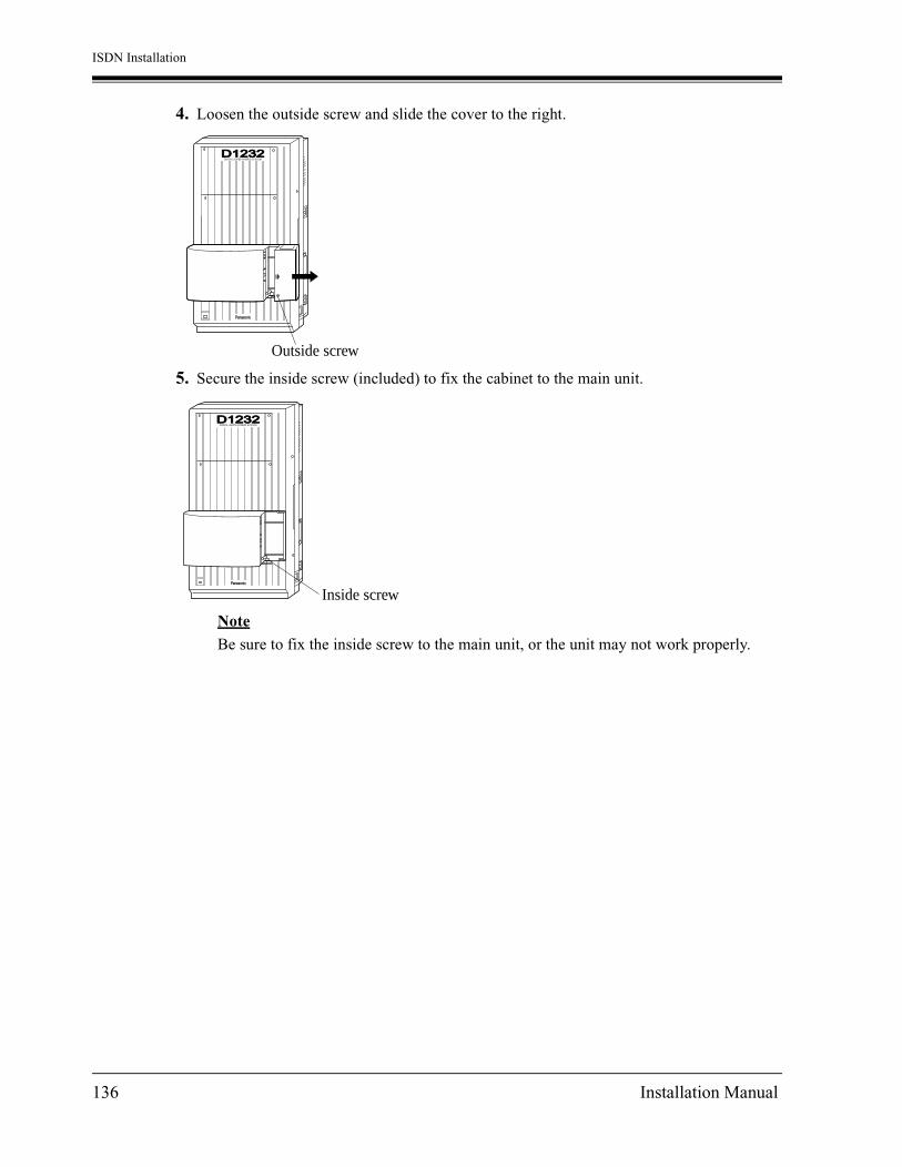
ISDN Installation
4. Loosen the outside screw and slide the cover to the right.
5. Secure the inside screw (included) to fix the cabinet to the main unit.
Note
Be sure to fix the inside screw to the main unit, or the unit may not work properly.
Panasonic
D1232DIGITAL SUPER HYBRID SYSTEM
Outside screw
Panasonic
D1232DIGITAL SUPER HYBRID SYSTEM
Inside screw
136 Installation Manual

ISDN Installation
6. Insert the 8-pin modular plug into a jack on the unit.
If a KX-TD382, KX-TD384 or KX-TD386 is to be installed:
Panasonic
2CO
ISDN DIG
ITAL SUPER HYBRID SYSTEM
2 U INTERFACE
Jack 2 (ISDN port 6)
Jack 1 (ISDN port 5)
View of TEL Jack (CO)
4:5:U-point
To Terminal Board orModular Jacks fromthe Central Office
To Terminal Board orModular Jacks fromthe Central Office
Panasonic
2CO w/PFT
ISDN DIG
ITAL SUPER HYBRID SYSTEM
4 U INTERFACE
Jack 2 (ISDN port 4)
Jack 1 (ISDN port 3)
Jack 4 (ISDN port 6)
Jack 3 (ISDN port 5)
View of TEL Jack (CO)
4:5:U-point
KX-TD382 KX-TD384
Panasonic
2CO w/PFT
ISDN DIG
ITAL SUPER HYBRID SYSTEM
6 U INTERFACE
Jack 2 (ISDN port 2)
Jack 1 (ISDN port 1)
Jack 4 (ISDN port 4)
Jack 3 (ISDN port 3)
Jack 6 (ISDN port 6)
Jack 5 (ISDN port 5)
View of TEL Jack (CO)
4:5:U-point
KX-TD386
To Terminal Board or ModularJacks from the Central Office
Installation Manual 137

ISDN Installation
If a KX-TD284 is to be installed:
a) Prepare the required plugs. (RJ45: plugs are not included in KX-TD284.)
b) Insert the plug into a jack on the unit.Connect a grounding wire to the ground terminal on the KX-TD284.
RATATBRB
←←←←
Pin No.3456
RATATBRB
←←←←
Pin No.3456
Wiring for external ISDN S0 line
Wiring for internal ISDN S0 line
← From Network
← From TerminalEquipment
* Pin 1, 2, 7 and 8 are not connected.
* Pin 1, 2, 7 and 8 are not connected.
Panasonic
2CO w/PFT
ISDN DIG
ITAL SUPER HYBRID SYSTEM
4 S/T INTERFACE
Jack 2 (ISDN port 4)
Jack 1 (ISDN port 3)
Jack 4 (ISDN port 6)
Jack 3 (ISDN port 5)
View of TEL Jack
3: TA4: RA5: RB6: TB
To Terminal Board orModular Jacks from NT-1
138 Installation Manual

ISDN Installation
If a KX-TD290 is to be installed (KX-TD1232 only):
Insert the plug into a jack on the unit.Connect a grounding wire to the ground terminal on the KX-TD290.
7. Tie all of the cords into a bundle. If other cords are exposed in the upper cabinets, tie them also.
8. Close the cabinet cover and secure the outside screw.
9. Cover the cords with the cord holder (included).
Panasonic
2CO w/PFT
View of TEL Jack (Outside Line)
Jack
1:2:
RA(Receive)
(Transmit)
RB4:5:
TBTA
To Terminal Board or ModularJacks from the Central Office
ISDN DIGITAL SUPER HYBRID SYSTEM
PRI
D1232DIGITAL SUPER HYBRID SYSTEM
Panasonic
Cord holder
Installation Manual 139

ISDN Installation
10.Fix the cords to the wall as shown so that the front cover can be opened.
Note
If two or three expansion units are installed, cut the cabinet covers on the lower cabinets to allow the cords from the upper cabinet to go down through the cabinet covers. To protect the cords, smooth the cut edges.
Programming Guide References[109] Expansion Unit Type
D1232DIGITAL SUPER HYBRID SYSTEM
Panasonic
Cut here
140 Installation Manual

T1 Installation
Section 4
T1 Installation
Installation Manual 141

T1 Installation
4.1 T1 Line Outline
4.1.1 Overview
To use the T1 Line, the following unit is required.
T1 Line Unit (KX-TD187)The unit adds 24 channels (outside line number 25 through 48 for KX-TD1232). If this unit is installed, other optional cards which extend outside lines cannot. This unit can be installed to any of the expansion unit areas provided on the front of the main unit.
Note
• KX-TD187 must be installed behind an FCC registered and UL or CSA-NRTL listed CSU.
• If you use the KX-TD170 with the KX-TD187, you must use the KX-TD170 which has suffix 'C' or later.The former KX-TD170 does not work properly with KX-TD187.Please see the back of the unit and check suffix.
How to distinguish suffix
• System Programming is required for card location identification.
The compatibility between KX-TD187 and KX-TD170
Master System Slave System
With KX-TD187 Suffix 'C' or later Don't care. *1
*1 KX-TD187 can not be installed in slave system.
Without KX-TD187 Don't care. Don't care. *1
Serial No. LABEL
Suffix UNIT No.
C
142 Installation Manual

T1 Installation
• The T1 Unit (KX-TD187) can be installed to the only master system of the KX-TD1232.
• In the case of system connection, the basic or extended outside lines in the slave system cannot be used.
• The capacity of outside lines is the follows.
Programming Guide References[109] Expansion Unit Type
Features Guide ReferencesModule Expansion
KX-TD1232 only 8
KX-TD187+KX-TD1232 32
KX-TD187+KX-TD1232 2(System connection)
32
Installation Manual 143

T1 Installation
4.2 T1 Line Installation
4.2.1 Location of the Unit
KX-TD1232One T1 Line Unit (KX-TD187) can be installed to any expansion area on the master system of KX-TD1232.
Note
• System Programming is required for expansion unit location.<SYS PRG [109]>Default : Area 1 = 4-CO Line Unit
Area 2 and 3 = 8-Station Line Unit
• As Section 1.4.2 Expansion Unit Combination.
Panasonic
D1232
T1
Expansionarea 2
Expansionarea 3
Expansionarea 1
Remove the front cover plate(s).
Expansion Unit Connectors
One T1 unit T1 unit, KX-TD187
144 Installation Manual
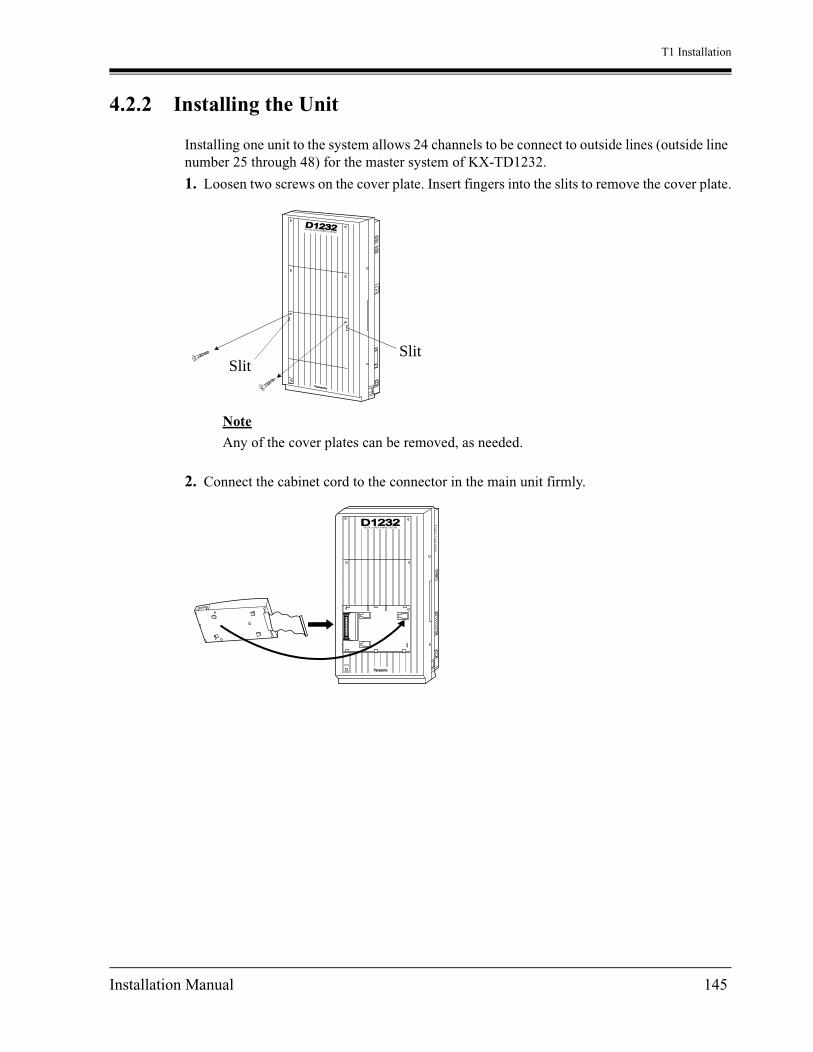
T1 Installation
4.2.2 Installing the Unit
Installing one unit to the system allows 24 channels to be connect to outside lines (outside line number 25 through 48) for the master system of KX-TD1232.
1. Loosen two screws on the cover plate. Insert fingers into the slits to remove the cover plate.
Note
Any of the cover plates can be removed, as needed.
2. Connect the cabinet cord to the connector in the main unit firmly.
SlitSlit
D1232DIGITAL SUPER HYBRID SYSTEM
Panasonic
Panasonic
D1232DIGITAL SUPER HYBRID SYSTEM
Installation Manual 145

T1 Installation
3. Hook the cabinet to the main unit and slide the cabinet to the left until it is secured.
4. Loosen the outside screw and slide the cover to the right.
5. Secure the inside screw (included) to fix the cabinet to the main unit.
Note
Be sure to fix the inside screw to the main unit, or the unit may not work properly.
Panasonic
D1232DEGITAL SUPER HYBRID SYSTEM
Panasonic
D1232DIGITAL SUPER HYBRID SYSTEM
Outside screw
Panasonic
D1232DIGITAL SUPER HYBRID SYSTEM
Inside screw
146 Installation Manual

T1 Installation
6. Insert the 8-pin modular plug into a jack on the unit.
7. Tie all of the cords into a bundle. If other cords are exposed in the upper cabinets, tie them also.
8. Close the cabinet cover and secure the outside screw.
9. Cover the cords with the cord holder (included).
Panasonic
T1 DIGITAL SUPER HYBRID SYSTEM
2CO w/PFT
View of TEL Jack (Outside Line)
Jack
1:2:
R1(Receive)
(Transmit)
T14:5:
RT
CSU CSU (Channel Service Unit)
D1232DIGITAL SUPER HYBRID SYSTEM
Panasonic
Cord holder
Installation Manual 147

T1 Installation
10.Fix the cords to the wall as shown so that the front cover can be opened.
Note
If two or three expansion units are installed, cut the cabinet covers on the lower cabinets to allow the cords from the upper cabinet to go down through the cabinet covers. To protect the cords, smooth the cut edges.
Programming References[109] Expansion Unit Type
D1232DIGITAL SUPER HYBRID SYSTEM
Panasonic
Cut here
148 Installation Manual

Troubleshooting
Section 5
Troubleshooting
This section provides information for system and telephone troubleshooting.
Installation Manual 149

Troubleshooting
5.1 Troubleshooting
5.1.1 Installation
PROBLEM PROBABLE CAUSE POSSIBLE SOLUTION
Extension does not operate. Bad printed circuit board (Extension Card).
Exchange printed circuit board for another printed circuit board.
Bad connection between the system and extension.
Take the extension and plug it into the same extension port using a short telephone cord. If the telephone does not work, the connection between the system and the extension must be repaired.
A telephone with an A-A1 relay is connected.
Use a 2 wire cord.
Set the A-A1 relay switch of the telephone to the "OUT" or "OFF" position.
Bad extension. Take the extension and plug it into another extension port that is working.
If the telephone does not work, replace the phone.
Incorrect reset operation. Press the Reset Button.
Noise in external paging. Induced noise on the wire between the system and the amplifier.
Use a shielded cable as the connection wire between the system and amplifier. A short shielded cable is recommended.
Volume distortion from external music source.
Excessive input level from external music source.
Decrease the output level of the external music source by using the volume control on the music source.
Speed Dialing or One-Touch Dialing does not function.
Bad programming. Enter the outside line access number (9, 81 through 88) into programming.
150 Installation Manual

Troubleshooting
5.1.2 Connection
Connection between the system and a proprietary telephone:
Can you dialan extension? The T / R is connected to the D1 / D2. Use the correct cord (inner 2
wires are for T / R and theouter 2 wires are for D1 / D2).
KX-TD816 / extensionKX-TD1232
KX-TD1232 extension
CAUSE SOLUTION
Use the correct cord (2second wires from theoutside are for D1 / D2 andthe 2 outer wires are forP1 / P2).
*The P1 / P2 is connected to the D1 / D2.
Yes
No
D1TR
D2
D1 TR D2
P1D1
TR
D2P2
P1D1 TR D2P2
The T / R is connected to the D1 / D2.
Connection between the system and a single line telephone:
Connection between the system and a single line telephone that is polarity-sensitive:
(Continued on the following.)
Use the correct cord (inner 2wires are for T / R).• If a telephone equipped with an A-A1 relay is connected to the system, set the A-A1 relay switch of the telephone to "OFF".KX-TD816 / extension
KX-TD1232
CAUSE SOLUTION
Connection between the system and a proprietary telephone:
D1TR
D2
TR
The "T" is connected to the "R". Reverse the connections ofthe T / R.
KX-TD816 / extensionKX-TD1232
CAUSE SOLUTION
D1TR
D2
TR
*: Available for the KX-TD1232 only.
Installation Manual 151
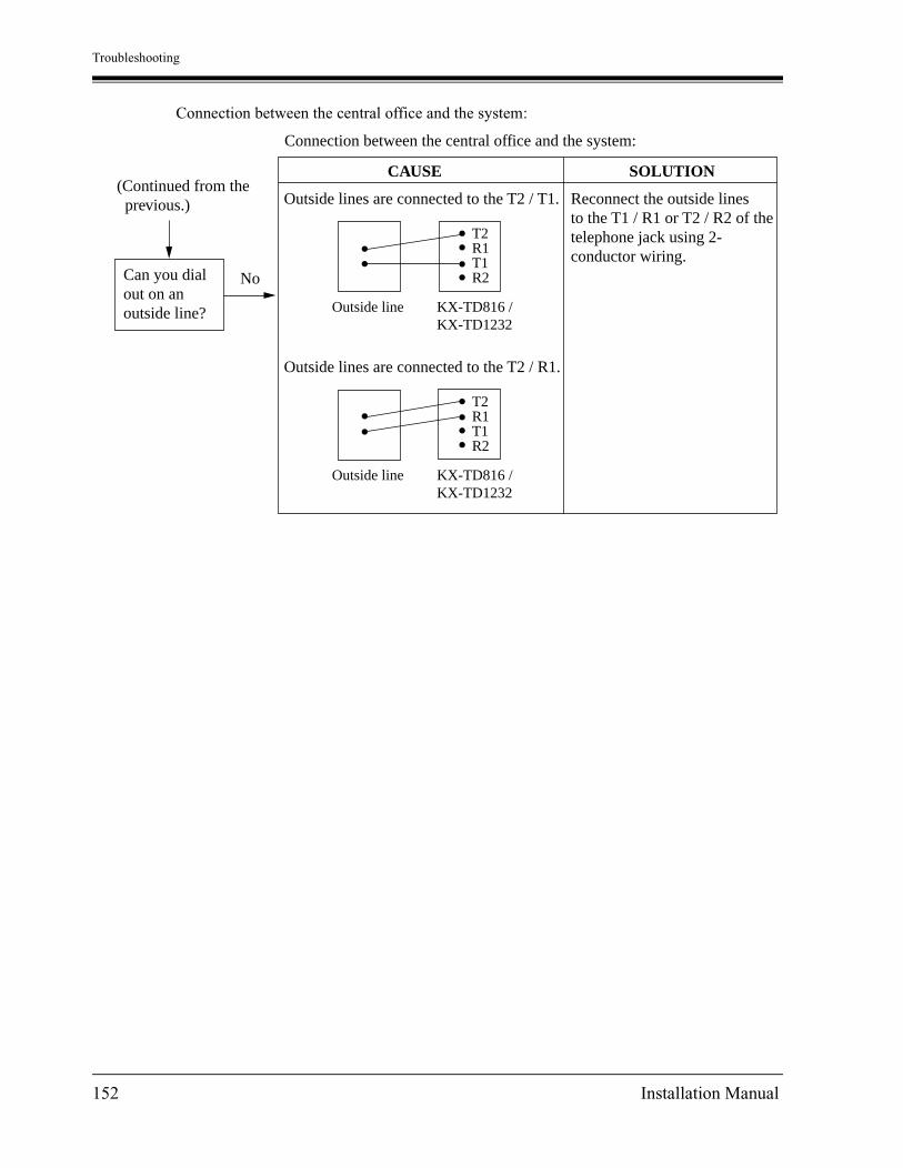
Troubleshooting
Connection between the central office and the system:
T2 R1T1R2 Can you dial
out on anoutside line?
No
Outside lines are connected to the T2 / T1.
Connection between the central office and the system:
(Continued from the previous.) Reconnect the outside lines
to the T1 / R1 or T2 / R2 of thetelephone jack using 2-conductor wiring.
Outside line KX-TD816 /KX-TD1232
Outside line KX-TD816 /KX-TD1232
CAUSE SOLUTION
Outside lines are connected to the T2 / R1.
T2 R1T1R2
152 Installation Manual

Troubleshooting
5.1.3 Operation
PROBLEM PROBABLE CAUSE POSSIBLE SOLUTION
• When using the speakerphone mode with a proprietary telephone KX-T7130 or KX-T7030, nothing is audible.
• The HANDSET / HEADSET selector of the KX-T7130 or KX-T7030 is set to the "HEADSET" position.
• When the headset is not used, set the HANDSET / HEADSET selector to the "HANDSET" position.
• When using the speakerphone / monitor mode with a digital proprietary telephone, nothing is audible.
• The "HEADSET" mode is selected by Station Programming, "Handset / Headset Selection".
• When the headset is not used, select the "HANDSET" mode by Station Programming.
The unit does not ring. The Ringer Volume Selector is set to "OFF".
Set to "HIGH" or "LOW".
During a power failure, extensions connected to jack numbers 1, 2, 9, 10 for KX-TD816, and 1, 2, 9, 10, 17, 18 for KX-TD1232 do not operate.
• A digital or analog proprietary telephone (DPT / APT) is connected to the jack.
• The dialing mode (tone or pulse) is improper.
• Disconnect the DPT or APT and connect a single line telephone.
• Set the Tone / Pulse switch to the other position.
During system connection operation for KX-TD1232, originating an intercom / outside call from one system to the other system is not possible.
Interface between the systems is disconnected.
Connect the interface between the systems and press the Reset Button on both systems.
Originating an outside call, Call Transfer, or Conference cannot be performed.
The corresponding CO button does not exist on the proprietary telephone.
Program the CO button. See Section [005] Flexible CO Button Assignment.
Installation Manual 153

Troubleshooting
5.1.4 Using the Reset Button
If the system does not operate properly, use the Reset Button.(If Master and Slave Systems are in operation by System Connection for KX-TD1232, reset both systems.)Before using the Reset Button, try the system feature again to confirm whether there definitely is a problem or not.
1. When the System Clear Switch is set to "NORMAL", pressing the Reset Button causes the following:
a) Camp-on is cleared.
b) Calls on Hold are terminated.
c) Calls on Exclusive Hold are terminated.
d) Calls in progress are terminated.
e) Call Park is cleared.
All other data stored in memory is not cleared.
2. When the System Clear Switch is set to the "CLEAR" position, you must press the Reset Button with caution. All data stored in memory will be cleared by the following operation: pressing the Reset Button and setting the System Clear Switch to the "NORMAL" position while the Power Indicator is flashing.
Operation1. If the system does not operate properly,
a) Make sure that the System Clear Switch is set to the "NORMAL" position.
b) Press the Reset Button with a pointed tool.
2. If the system still does not operate properly,
a) Set the System Clear Switch to the "CLEAR" position.
b) Press the Reset Button with a pointed tool.
c) Return the System Clear Switch to the "NORMAL" position while the Power Indicator is flashing (approximately within 10 seconds).
3. If the system still does not work, switch the power off and on again after five minutes.
4. If the system still does not work,
a) Switch the power off.
b) Set the System Clear Switch to the "CLEAR" position.
c) Switch the power on.
d) Press the Reset Button with a pointed tool.
e) Set the System Clear Switch to the "NORMAL" position while the Power Indicator is flashing (approximately within 10 seconds).
154 Installation Manual
Troubleshooting
5. If the system still does not work, switch the power off. Then consult an authorized service person.
When the power supply stops, certain extensions are automatically connected straight to specific analog outside lines:
KX-TD816
Extension (T, R) of jack number 1: Outside line 1
Extension (T, R) of jack number 2: Outside line 2
Extension (T, R) of jack number 9: Outside line 5
Extension (T, R) of jack number 10: Outside line 6
KX-TD1232
Extension (T, R) of jack number 1: Outside line 1
Extension (T, R) of jack number 2: Outside line 2
Extension (T, R) of jack number 9: Outside line 3
Extension (T, R) of jack number 10: Outside line 4
Extension (T, R) of jack number 17: Outside line 9
Extension (T, R) of jack number 18: Outside line 10
Connect single line telephones to the above extension jacks.
Installation Manual 155

Troubleshooting
156 Installation Manual

Index
Section 6
Index
157

Index
Numerics2-ISDN Unit (KX-TD382) 274-CO Line Unit (KX-TD180) 274-DID Line Unit (KX-TD185) 274-ISDN Unit (KX-TD284) 274-ISDN Unit (KX-TD384) 276-ISDN Unit (KX-TD384) 278-Station Line Unit (KX-TD170) 278-Station Line Unit with SLT CID (KX-TD171)
27
AAmphenol 57JE Type 88Automatic Route Selection (ARS) 19Auxiliary Connection for Power Failure Transfer
121
BBasic System Construction 21Before Installation 36
CCaller ID 20Caller ID Card (KX-TD193) 27Characteristics 33, 110Closing the Front Cover 116, 123
DDigital Proprietary Telephones (DPT) 19DISA Card 90, 94DISA Card (KX-TD191) 27, 90Door Opener Connection 99Doorphone 99Doorphone (KX-T30865) 28Doorphone Card 75, 100, 101Doorphone Card (KX-TD160) 28Doorphone Card (KX-TD161) 28Doorphone Connection 99DSS Console (KX-T7440 / KX-T7441 / KX-T7240
/ KX-T7040) 28
EExpansion Unit Combination 29Extension Connection 47External Music Source Connection 64External Pager (Paging Equipment) Connection
62EXtra Device Port (XDP) 18EXtra Device Port (XDP) Connection 59
FFrame Ground Connection 44, 112
158
GGeneral Description 31Ground 138ground 112
HHigh Speed Remote Card 75High Speed Remote Card (KX-TD197) 28, 90,
95High Speed Remote Unit (KX-TD198) 28
IInstalling Expansion Unit 82ISDN Line Connection 132ISDN Line Service 19, 130
KKX-T30865 (Doorphone) 28KX-T7440 / KX-T7441 / KX-T7240 / KX-T7040
(DSS Console) 28KX-TD112 (PLL (Phase Locked Loops) Card)
76KX-TD112 (PLL Card) 28KX-TD160 (Doorphone Card) 28KX-TD161 (Doorphone Card) 28KX-TD170 (8-Station Line Unit) 27KX-TD171 (8-Station Line Unit with SLT CID)
27KX-TD180 (4-CO Line Unit) 27KX-TD185 (4-DID Line Unit) 27KX-TD187 (T-1 Unit) 27KX-TD191 (DISA Card) 27KX-TD192 (System Inter Connection Card) 27KX-TD193 (Caller ID Card) 27KX-TD194 (SLT Message Waiting Lamp Adaptor
Unit) 28KX-TD196 (Remote Card) 28KX-TD197 (High Speed Remote Card) 28KX-TD198 (Remote Unit) 28KX-TD284 (4-ISDN Unit) 27KX-TD290 (Primary Rate Interface ISDN Expan-
sion Unit) 27KX-TD382 (2-ISDN Unit) 27KX-TD384 (4-ISDN Unit) 27KX-TD386 (6-ISDN Unit) 27
LLightning Protectors 70Location of Interfaces 39Location of Optional Cards and Units 73Location of the Unit 144Location of the Units 132

Index
MMaximum Cabling Distance 47, 48Module Expansion 18
OOpening Front Cover 43Opening the front cover 111Options 27Outside Line Connection 45
PParalleled Telephone Connection 18, 57Pin Number Chart 51PLL (Phase Locked Loops) Card (KX-TD112)
76PLL Card (KX-TD112) 28Polarity Sensitive Telephone Connection 60Power Failure Transfer 121Primary Rate Interface ISDN Expansion Unit (KX-
TD290) 27Printer and PC Connection 66Programming System 19Proprietary Telephones 26
RRemote Card 90Remote Card (KX-TD196) 28, 90, 95Remote Card, System Inter Connection Card, DISA
Card, Doorphone Card 75Remote Station Lock Control 20Remote Unit (KX-TD198) 90, 92Reset Button 125, 126, 127, 128, 154
SSerial Interface (RS-232C) Signals 68SLT Message Waiting Lamp Adaptor Unit 77SLT Message Waiting Lamp Adaptor Unit (KX-
TD194) 28SLT Message Waiting Lamp Adaptor Unit
Connection 110Specifications 110Starting the System for the First Time 125Super Hybrid System 18System Capacity 34System Clear Switch 125, 127, 128, 154System Connection 19, 118System Connection Diagram 22System Highlights 18System Inter Connection Card 118System Inter Connection Card (KX-TD192) 27System Maximum Capacity 18
TT1 Line 142
T1 Line Installation 144T1 Line Service 19T-1 Unit (KX-TD187) 27Telephone Connection 54Telephone Wiring 47, 48TIE Line Service 19Trunk (Outside Line) Answer From Any Station
(TAFAS) 20
UUniform Call Distribution (UCD) 20Unpacking 38
VVoice Mail Integration 19
WWall Mounting 41
159

PSQX2576YA KA0801HK1052Printed in the United Kingdom
This manual is copyrighted by Kyushu Matsushita Electric Co., Ltd. (KME). Under the applicable copyrightlaws, this manual may not be reproduced in any form, in whole or part, without the prior written consent of KME and its licensee.
2001 Kyushu Matsushita Electric Co., Ltd. All Rights Reserved.C
Copyright:
See MorePanasonic Manuals
www.voicesonic.comPhone: 877-289-2829
Panasonic Telephone Systems