Pan India & HIVECTOL HVI E Global Presence …...HIVECTOL HVI E Medium Voltage Multi Level Drives...
7
HIVECTOL - HVI - E Medium Voltage Multi-Level Drives Range upto 14.7 mVA (3.3 kV to 11 kV) Mining Water & Waste Water Rubber Sugar and many more...
Transcript of Pan India & HIVECTOL HVI E Global Presence …...HIVECTOL HVI E Medium Voltage Multi Level Drives...
HIVECTOL HVI E Medium Voltage MultiLevel DrivesRange upto 14.7 mVA (3.3 kV to 11 kV)
Mining
Water & Waste Water
Rubber
Sugar
and many more...
MV
/ 0
3 /
15
/ V
er.2
.1 /
Co
rp.
Mktg
. /
Ind
ia S
po
tlig
ht
- 0
79
30
02
23
24
l
Hitachi Australia Pty. Ltd.
Pan India & Global Presence
In the spirit of continuous improvement, specifications are subject to change without notice.
USA
Middle East
South East AsiaAfrica
Australia
India
Suite 801, Level 8, 123, Epping Road, North Ryde NSW 2113 Phone: +61 2 9888 4100 Fax: +61 2 9888 4188Web: www.hitachi.com.au
02Range up to 14.7 mVA (3.3 kV to 11 kV)
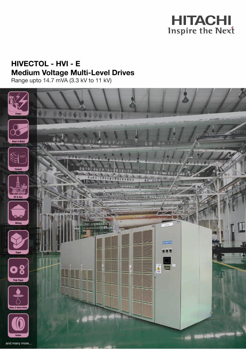
We, Hitachi Hi-Rel Power Electronics Pvt. Ltd., offer HIVECTOL-
HVI-E series medium voltage multi level IGBT drives up to
14.7mVA, voltage range 3.3kV, 6.6kV and 11kV.
Today we offer our customers the most appropriate digital
technology, in AC drives, tailored to their specific application
requirements. Sanand, India based our local manufacturing
facility ensures long term technical services and spares support.
Local manufacturing will help Indian customers to avail best in
class product with long term commitment of Spares and
Services. This will also help customer to carry out FAT and train
their maintenance engineers.
MAIN FEATURES
Medium Voltage MultiLevel Drives HIVECTOL HVI E
This world class manufacturing set up of Drives adopts work
culture, design, manufacturing process, component selection,
and quality and testing standards that are being followed at
Hitachi Japan manufacturing facilities.Multi Cell topology of drive
uses low voltage devices. It is user friendly and easy to maintain
by customer.
Drive is forced air cooled. Different voltage ratings 3.3kV, 6.6kV
and 11kV are available. Intermittent ratings like 3kV, 4.16kV, 6kV
are also available.
In house regeneration drive test facility is capable to demonstrate
drive characterization during FAT.
Suitable for Indian Ambient condition
Designed for 50 degree centigrade except few ratings.
Input Harmonics Meets IEEE 519 1992
Multilpulse rectifier method reduces input side harmonics
and conforms better than IEEE 519 - 1992 recommended
performance without use of harmonic filters.
No special care needs to be taken in K-rating of the input
transformer, cables, switch-gear components, etc.
Output Waveform Motor Friendly
Series connected LV IGBT cell inverter technology gives
advantages like
It controls the output waveform distortion and approximates
it to sine waveform. Insignificant over heating due to
harmonics is observed.
Voltage spikes observed at the motor winding is limited to
less than 1000 V. This performance does not add any
stresses on the motor insulation.
Both the above features allow use of existing motor on
variable torque load.
Suitable for Induction and Synchronous motor application.
Best for High Starting Torque
Robust Sensor less vector control method provides smooth
starting and operation with high torque loads without use of
special feedback sensor.
Hence this drive is most suitable for Rubber Mixer, Extruders,
Agitators etc in addition to Pump and Fan applications.
Patented Design Increases Reliability
PreCharging - It reduces charging inrush current of the transformer to
less than its rated current. Normal charging method
requires large charging current for equivalent rating
transformer.
- Pre charge of the DC Filter capacitors in each cell is
carried out using external pre charge circuit. These
components are bypassed from the main power path and
hence increase the reliability of the overall system.
- No change in existing electrical system required while
going for retrofitting of energy saving application.
Cyclic Switching of the Cells - Cyclic switching achieves equal utilization of each cell at
any operating speed. It ensures even heating and
stresses on each component. It increases the reliability of
the drive.
High Efficiency
Typical 97% efficiency including input Dry type transformer.
Auto Restart
If power resumes within 2 secs, no waiting period to restart. It
has capability to catch a running motor. The coasting motor
can be reaccelerated to the reference speed automatically.
User friendly
Touch screen display Parameter setting through
maintenance PC using passes word.
Easy to maintain
MV drive cells are manufactured using standard low voltage
Diode, IGBTs and Capacitors. Reliability of the individual cell
is greatly enhanced due to high reliability of these devices.
User can easily maintain these cells due to very familiar
topology and easy availability of main components and
training from local manufacturing set up.
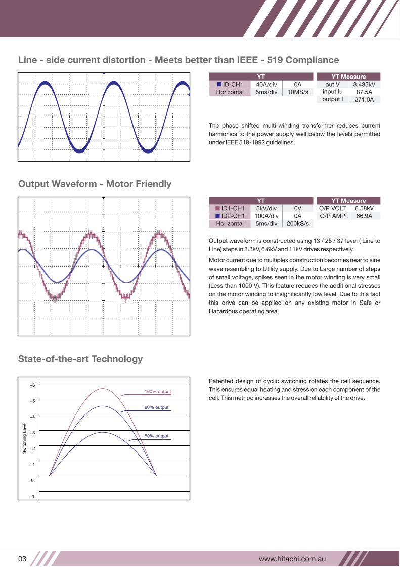
40A/div 0A
Horizontal
out V 3.435kVinput lu 87.5A
YT MeasureYT
www.hitachi.com.au03
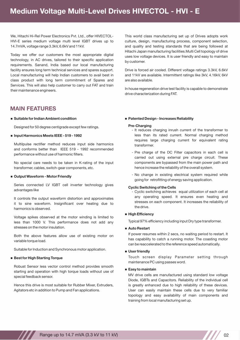
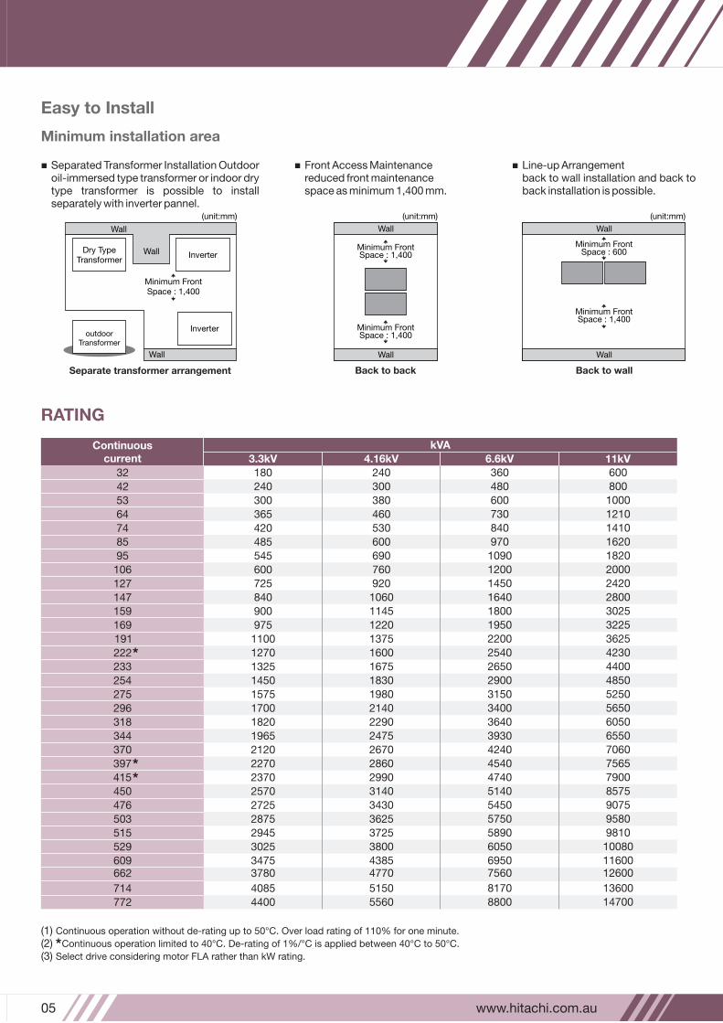
Patented design of cyclic switching rotates the cell sequence.
This ensures equal heating and stress on each component of the
cell. This method increases the overall reliability of the drive.
Stateoftheart Technology
100% output
80% output
50% output
+6
+5
+4
+3
+2
+1
0
-1
Sw
itchin
g L
eve
l
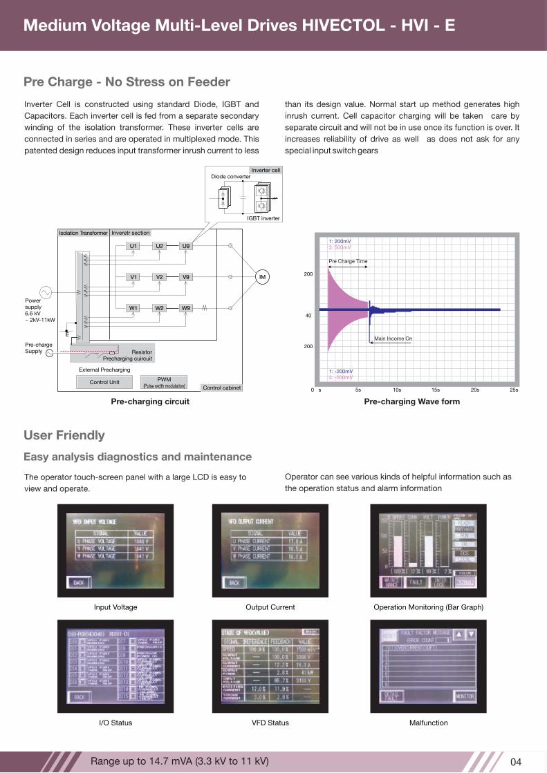
Output waveform is constructed using 13 / 25 / 37 level ( Line to
Line) steps in 3.3kV, 6.6kV and 11kV drives respectively.
Motor current due to multiplex construction becomes near to sine
wave resembling to Utility supply. Due to Large number of steps
of small voltage, spikes seen in the motor winding is very small
(Less than 1000 V). This feature reduces the additional stresses
on the motor winding to insignificantly low level. Due to this fact
this drive can be applied on any existing motor in Safe or
Hazardous operating area.
Output Waveform Motor Friendly
The phase shifted multi-winding transformer reduces current
harmonics to the power supply well below the levels permitted
under IEEE 519-1992 guidelines.
Line side current distortion Meets better than IEEE 519 Compliance
ID-CH1
10MS/s
YT MeasureYT
ID1-CH1 5kV/div 0V
ID2-CH1 100A/div 0A
Horizontal 5ms/div 200kS/s
O/P VOLT 6.58kV
O/P AMP 66.9A
output l 271.0A
5ms/div 10MS/s
02Range up to 14.7 mVA (3.3 kV to 11 kV)
We, Hitachi Hi-Rel Power Electronics Pvt. Ltd., offer HIVECTOL-
HVI-E series medium voltage multi level IGBT drives up to
14.7mVA, voltage range 3.3kV, 6.6kV and 11kV.
Today we offer our customers the most appropriate digital
technology, in AC drives, tailored to their specific application
requirements. Sanand, India based our local manufacturing
facility ensures long term technical services and spares support.
Local manufacturing will help Indian customers to avail best in
class product with long term commitment of Spares and
Services. This will also help customer to carry out FAT and train
their maintenance engineers.
MAIN FEATURES
Medium Voltage MultiLevel Drives HIVECTOL HVI E
This world class manufacturing set up of Drives adopts work
culture, design, manufacturing process, component selection,
and quality and testing standards that are being followed at
Hitachi Japan manufacturing facilities.Multi Cell topology of drive
uses low voltage devices. It is user friendly and easy to maintain
by customer.
Drive is forced air cooled. Different voltage ratings 3.3kV, 6.6kV
and 11kV are available. Intermittent ratings like 3kV, 4.16kV, 6kV
are also available.
In house regeneration drive test facility is capable to demonstrate
drive characterization during FAT.
Suitable for Indian Ambient condition
Designed for 50 degree centigrade except few ratings.
Input Harmonics Meets IEEE 519 1992
Multilpulse rectifier method reduces input side harmonics
and conforms better than IEEE 519 - 1992 recommended
performance without use of harmonic filters.
No special care needs to be taken in K-rating of the input
transformer, cables, switch-gear components, etc.
Output Waveform Motor Friendly
Series connected LV IGBT cell inverter technology gives
advantages like
It controls the output waveform distortion and approximates
it to sine waveform. Insignificant over heating due to
harmonics is observed.
Voltage spikes observed at the motor winding is limited to
less than 1000 V. This performance does not add any
stresses on the motor insulation.
Both the above features allow use of existing motor on
variable torque load.
Suitable for Induction and Synchronous motor application.
Best for High Starting Torque
Robust Sensor less vector control method provides smooth
starting and operation with high torque loads without use of
special feedback sensor.
Hence this drive is most suitable for Rubber Mixer, Extruders,
Agitators etc in addition to Pump and Fan applications.
Patented Design Increases Reliability
PreCharging - It reduces charging inrush current of the transformer to
less than its rated current. Normal charging method
requires large charging current for equivalent rating
transformer.
- Pre charge of the DC Filter capacitors in each cell is
carried out using external pre charge circuit. These
components are bypassed from the main power path and
hence increase the reliability of the overall system.
- No change in existing electrical system required while
going for retrofitting of energy saving application.
Cyclic Switching of the Cells - Cyclic switching achieves equal utilization of each cell at
any operating speed. It ensures even heating and
stresses on each component. It increases the reliability of
the drive.
High Efficiency
Typical 97% efficiency including input Dry type transformer.
Auto Restart
If power resumes within 2 secs, no waiting period to restart. It
has capability to catch a running motor. The coasting motor
can be reaccelerated to the reference speed automatically.
User friendly
Touch screen display Parameter setting through
maintenance PC using passes word.
Easy to maintain
MV drive cells are manufactured using standard low voltage
Diode, IGBTs and Capacitors. Reliability of the individual cell
is greatly enhanced due to high reliability of these devices.
User can easily maintain these cells due to very familiar
topology and easy availability of main components and
training from local manufacturing set up.
40A/div 0A
Horizontal
out V 3.435kVinput lu 87.5A
YT MeasureYT
www.hitachi.com.au03
Patented design of cyclic switching rotates the cell sequence.
This ensures equal heating and stress on each component of the
cell. This method increases the overall reliability of the drive.
Stateoftheart Technology
100% output
80% output
50% output
+6
+5
+4
+3
+2
+1
0
-1
Sw
itchin
g L
eve
l
Output waveform is constructed using 13 / 25 / 37 level ( Line to
Line) steps in 3.3kV, 6.6kV and 11kV drives respectively.
Motor current due to multiplex construction becomes near to sine
wave resembling to Utility supply. Due to Large number of steps
of small voltage, spikes seen in the motor winding is very small
(Less than 1000 V). This feature reduces the additional stresses
on the motor winding to insignificantly low level. Due to this fact
this drive can be applied on any existing motor in Safe or
Hazardous operating area.
Output Waveform Motor Friendly
The phase shifted multi-winding transformer reduces current
harmonics to the power supply well below the levels permitted
under IEEE 519-1992 guidelines.
Line side current distortion Meets better than IEEE 519 Compliance
ID-CH1
10MS/s
YT MeasureYT
ID1-CH1 5kV/div 0V
ID2-CH1 100A/div 0A
Horizontal 5ms/div 200kS/s
O/P VOLT 6.58kV
O/P AMP 66.9A
output l 271.0A
5ms/div 10MS/s
Easy to Install
Minimum installation area
Separated Transformer Installation Outdoor oil-immersed type transformer or indoor dry type transformer is possible to install separately with inverter pannel.
Line-up Arrangement back to wall installation and back to back installation is possible.
Separate transformer arrangement
Dry TypeTransformer
Inverter
Inverter
Minimum FrontSpace : 1,400
Wall
Wall
Wall
(unit:mm)
outdoorTransformer
Back to wall
Minimum FrontSpace : 600
(unit:mm)
Wall
Minimum FrontSpace : 1,400
Wall
(unit:mm)
Wall
Minimum FrontSpace : 1,400
Minimum FrontSpace : 1,400
Wall
Back to back
Front Access Maintenance reduced front maintenance space as minimum 1,400 mm.
www.hitachi.com.au05
RATING
(1) Continuous operation without de-rating up to 50°C. Over load rating of 110% for one minute.
(2) Continuous operation limited to 40°C. De-rating of 1%/°C is applied between 40°C to 50°C.
(3) Select drive considering motor FLA rather than kW rating.
Continuous current
kVA
3.3kV 4.16kV 6.6kV 11kV
180
240
300
365
420
485
545
600
725
840
900
975
1100
1270
1325
1450
1575
1700
1820
1965
2120
2270
2370
2570
2725
2875
2945
3025
34753780
4085
4400
240
300
380
460
530
600
690
760
920
1060
1145
1220
1375
1600
1675
1830
1980
2140
2290
2475
2670
2860
2990
3140
3430
3625
3725
3800
43854770
5150
5560
360
480
600
730
840
970
1090
1200
1450
1640
1800
1950
2200
2540
2650
2900
3150
3400
3640
3930
4240
4540
4740
5140
5450
5750
5890
6050
69507560
8170
8800
600
800
1000
1210
1410
1620
1820
2000
2420
2800
3025
3225
3625
4230
4400
4850
5250
5650
6050
6550
7060
7565
7900
8575
9075
9580
9810
10080
1160012600
13600
14700
32
42
53
64
74
85
95
106
127
147
159
169
191
222
233
254
275
296
318
344
370
397
415
450
476
503
515
529
609662
714
772
User Friendly
Easy analysis diagnostics and maintenance
The operator touch-screen panel with a large LCD is easy to
view and operate.
Operation Monitoring (Bar Graph)Input Voltage Output Current
I/O Status VFD Status Malfunction
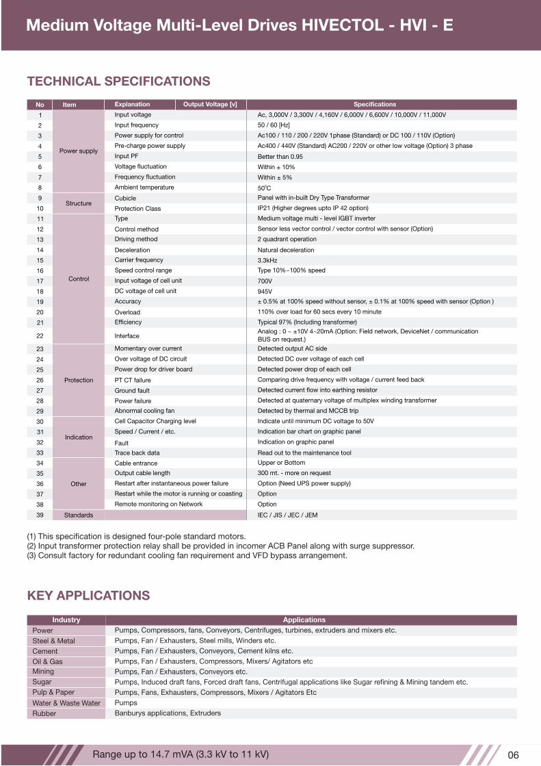
Pre Charge No Stress on Feeder
Inverter Cell is constructed using standard Diode, IGBT and
Capacitors. Each inverter cell is fed from a separate secondary
winding of the isolation transformer. These inverter cells are
connected in series and are operated in multiplexed mode. This
patented design reduces input transformer inrush current to less
U1 U2 U9
V1 V2 V9
W1 W2 W9
E
IM
Isolation Transformer Inveretr section
Power supply6.6 kV~ 2kV-11kW
Pre-chargeSupply
Control Unit PWM(Pulse width modulation) Control cabinet
ResistorPrecharging cuircuit
External Precharging
Precharging circuit
Pre Charge Time
Main Income On
200
40
0 s 5s 10s 15s 20s 25s
200
1: 200mV 3: 500mV
1: -200mV 3: -500mV
Precharging Wave form
Inverter cellDiode converter
IGBT inverter
than its design value. Normal start up method generates high
inrush current. Cell capacitor charging will be taken care by
separate circuit and will not be in use once its function is over. It
increases reliability of drive as well as does not ask for any
special input switch gears
Operator can see various kinds of helpful information such as
the operation status and alarm information
04Range up to 14.7 mVA (3.3 kV to 11 kV)
Medium Voltage MultiLevel Drives HIVECTOL HVI E
Easy to Install
Minimum installation area
Separated Transformer Installation Outdoor oil-immersed type transformer or indoor dry type transformer is possible to install separately with inverter pannel.
Line-up Arrangement back to wall installation and back to back installation is possible.
Separate transformer arrangement
Dry TypeTransformer
Inverter
Inverter
Minimum FrontSpace : 1,400
Wall
Wall
Wall
(unit:mm)
outdoorTransformer
Back to wall
Minimum FrontSpace : 600
(unit:mm)
Wall
Minimum FrontSpace : 1,400
Wall
(unit:mm)
Wall
Minimum FrontSpace : 1,400
Minimum FrontSpace : 1,400
Wall
Back to back
Front Access Maintenance reduced front maintenance space as minimum 1,400 mm.
www.hitachi.com.au05
RATING
(1) Continuous operation without de-rating up to 50°C. Over load rating of 110% for one minute.
(2) Continuous operation limited to 40°C. De-rating of 1%/°C is applied between 40°C to 50°C.
(3) Select drive considering motor FLA rather than kW rating.
Continuous current
kVA
3.3kV 4.16kV 6.6kV 11kV
180
240
300
365
420
485
545
600
725
840
900
975
1100
1270
1325
1450
1575
1700
1820
1965
2120
2270
2370
2570
2725
2875
2945
3025
34753780
4085
4400
240
300
380
460
530
600
690
760
920
1060
1145
1220
1375
1600
1675
1830
1980
2140
2290
2475
2670
2860
2990
3140
3430
3625
3725
3800
43854770
5150
5560
360
480
600
730
840
970
1090
1200
1450
1640
1800
1950
2200
2540
2650
2900
3150
3400
3640
3930
4240
4540
4740
5140
5450
5750
5890
6050
69507560
8170
8800
600
800
1000
1210
1410
1620
1820
2000
2420
2800
3025
3225
3625
4230
4400
4850
5250
5650
6050
6550
7060
7565
7900
8575
9075
9580
9810
10080
1160012600
13600
14700
32
42
53
64
74
85
95
106
127
147
159
169
191
222
233
254
275
296
318
344
370
397
415
450
476
503
515
529
609662
714
772
User Friendly
Easy analysis diagnostics and maintenance
The operator touch-screen panel with a large LCD is easy to
view and operate.
Operation Monitoring (Bar Graph)Input Voltage Output Current
I/O Status VFD Status Malfunction
Pre Charge No Stress on Feeder
Inverter Cell is constructed using standard Diode, IGBT and
Capacitors. Each inverter cell is fed from a separate secondary
winding of the isolation transformer. These inverter cells are
connected in series and are operated in multiplexed mode. This
patented design reduces input transformer inrush current to less
U1 U2 U9
V1 V2 V9
W1 W2 W9
E
IM
Isolation Transformer Inveretr section
Power supply6.6 kV~ 2kV-11kW
Pre-chargeSupply
Control Unit PWM(Pulse width modulation) Control cabinet
ResistorPrecharging cuircuit
External Precharging
Precharging circuit
Pre Charge Time
Main Income On
200
40
0 s 5s 10s 15s 20s 25s
200
1: 200mV 3: 500mV
1: -200mV 3: -500mV
Precharging Wave form
Inverter cellDiode converter
IGBT inverter
than its design value. Normal start up method generates high
inrush current. Cell capacitor charging will be taken care by
separate circuit and will not be in use once its function is over. It
increases reliability of drive as well as does not ask for any
special input switch gears
Operator can see various kinds of helpful information such as
the operation status and alarm information
04Range up to 14.7 mVA (3.3 kV to 11 kV)
Medium Voltage MultiLevel Drives HIVECTOL HVI E
(1) This specification is designed four-pole standard motors. (2) Input transformer protection relay shall be provided in incomer ACB Panel along with surge suppressor.(3) Consult factory for redundant cooling fan requirement and VFD bypass arrangement.
TECHNICAL SPECIFICATIONS
Industry Applications
Pumps, Compressors, fans, Conveyors, Centrifuges, turbines, extruders and mixers etc.
Pumps, Fan / Exhausters, Steel mills, Winders etc.
Pumps, Fan / Exhausters, Conveyors, Cement kilns etc.
Pumps, Fan / Exhausters, Conveyors etc.
Pumps
Pumps, Fan / Exhausters, Compressors, Mixers/ Agitators etc
Pumps, Induced draft fans, Forced draft fans, Centrifugal applications like Sugar refining & Mining tandem etc.
Pumps, Fans, Exhausters, Compressors, Mixers / Agitators Etc
Banburys applications, Extruders
KEY APPLICATIONS
Power supply
Input voltage
Input frequency
Power supply for control
Pre-charge power supply
Voltage fluctuation
Frequency fluctuation
Structure
Ambient temperature
Cubicle
Protection Class
Panel with in-built Dry Type Transformer
IP21 (Higher degrees upto IP 42 option)
Ac, 3,000V / 3,300V / 4,160V / 6,000V / 6,600V / 10,000V / 11,000V
50 / 60 [Hz]
Ac100 / 110 / 200 / 220V 1phase (Standard) or DC 100 / 110V (Option)
Ac400 / 440V (Standard) AC200 / 220V or other low voltage (Option) 3 phase
Within ± 10%
Within ± 5%050 C
Control
Type
Control method
Driving method
Deceleration
Carrier frequency
Speed control range
Input voltage of cell unit
DC voltage of cell unit
Accuracy
Overload
Efficiency
Interface
Medium voltage multi - level IGBT inverter
Sensor less vector control / vector control with sensor (Option)
2 quadrant operation
Natural deceleration
3.3kHz
Type 10%~100% speed
700V
945V
± 0.5% at 100% speed without sensor, ± 0.1% at 100% speed with sensor (Option )
110% over load for 60 secs every 10 minute
Typical 97% (Including transformer)
Analog : 0 ~ ±10V 4~20mA (Option: Field network, DeviceNet / communication BUS on request.)
Other
Protection
Cell Capacitor Charging level
Speed / Current / etc.
Fault
Trace back data
Cable entrance
Output cable length
Restart after instantaneous power failure
Restart while the motor is running or coasting
Standards
Remote monitoring on Network
Indicate until minimum DC voltage to 50V
Indication bar chart on graphic panel
Indication on graphic panel
Read out to the maintenance tool
Upper or Bottom
300 mt. - more on request
Option (Need UPS power supply)
Option
Option
IEC / JIS / JEC / JEM
Momentary over current
Over voltage of DC circuit
Power drop for driver board
PT CT failure
Ground fault
Power failure
Abnormal cooling fan
Detected output AC side
Detected DC over voltage of each cell
Detected power drop of each cell
Comparing drive frequency with voltage / current feed back
Detected current flow into earthing resistor
Detected at quaternary voltage of multiplex winding transformer
Detected by thermal and MCCB trip
Indication
No SpecificationsItem Explanation
1
2
3
4
5
6
7
8
9
10
11
12
13
14
15
16
17
18
19
20
21
22
23
24
25
26
27
28
29
30
31
32
33
34
35
36
37
38
Input PF Better than 0.95
39
Output Voltage [v]
Power
Steel & Metal
Cement
Mining
Water & Waste Water
Oil & Gas
Sugar
Pulp & Paper
Rubber
06Range up to 14.7 mVA (3.3 kV to 11 kV)
Medium Voltage MultiLevel Drives HIVECTOL HVI E
www.hitachi.com.au07
About Us
We believe that our core Values, Customer Delight, Quality Orientation, Harmony, Sincerity, Pioneering Spirit & Growth, differentiate us from others. With Expertise, Experience and an Efficient Product Line, we will always be your Power Electronics Partner.
When you choose to do business with us, you are partnering with a Company who cares.
Sanand, India Works
Most Modern Power Electronics Manufacturing Facility in India Modelled on Hitachi's Omika Works, Japan
2 Total Area - 26,000 m Products Manufacturing - Medium & Low Voltage Drives, Industrial Automation & Control, Customized Products i.e. UMPS, iDip Facilities � Designing, Engineering, Manufacturing and Testing Use of Hitachi's Omika Works based Software Tools for Engineering and Manufacturing Dust Free Environment and Anti-static Flooring In-house Product Testing Facility
3 MV Drives Test bays 5 LV Drives Test bays
Automatic Cell Testing Facility Test 11 kW to 550 kW ratings at 340 V and 415 V Drives on full
power with motor load Full characterization up to 1460 kW ratings at 3.3 kV and 6.6kV
drives on full power with regenerative motor load facility Test up to 5000 kW ratings at 3.3 kV, 6.6 kV, and 11 kV drives on
full current with reactor load Customer can conduct Witness Test from Automated Test
Command Centre
All LV and MV test field's input and output breakers & contactors are PLC controlled Load selection also PLC controlled
Drive input and output parameters available on PC through PLC Load details are available on PC through PLC
Founded and established in 1983 as Hi-Rel Electronics Pvt. Ltd., we are now a Hitachi Group Company - Hitachi Hi-Rel Power Electronics Pvt. Ltd., recognized as a PIONEER IN POWER ELECTRONICS. With 3 Decades of Experience, we have garnered a significant level of trust in our Market Segment and continue to offer World Class Power Electronics Products, Value Added Services & Customized Solutions.
Our Product Portfolio includes UPS (Uninterruptible Power Supply) for Industrial, Commercial & Enterprise Applications, Medium Voltage & Low Voltage Variable Frequency Drives, Steel Automation & Engineered Drives for Customized Applications, Industrial Automation & Control Products like PLC, SCADA & DCS, Grid Tied Solar PCS, Railway Products and other Customized Products like UMPS, iDip (Dip Ride Through Solutions), etc. We have rich experience in supplying power back-up products & complete Customized Solutions for Mission Critical Applications in Refineries, Petro-Chemicals, Power Generation, Steel & Metal, and Process Industries as well as Critical Data Processing Applications.
Leading Manufacturer of UPS, DRIVES & AUTOMATION PRODUCTS and GRID TIED SOLAR INVERTER State-of-The-Art MANUFACTURING FACILITY AT Gandhinagar & Sanand in Gujarat, India IN-HOUSE R&D Facility recognized by DSIR, Government of India ISO 9001: 2008, ISO 14001: 2004 & BS OHSAS 18001:2007 Certified Company adhering to World Class Quality Standards APPROVED by Leading Consultants and EPC Vendors PAN INDIA & GLOBAL Presence SERVING Entire Gamut of Industries Rich Experience in “MISSION CRITICAL” Applications Dedicated & Decentralized 24X7 AFTER-SALES SERVICE at 45+ Locations OFFER Products with Greater Energy Efficiency & Lower Carbon Footprint carbon footprint
We constantly strive to offer our Customers Complete Customized Solutions to keep them ahead in this Competitive Arena. Product Development is a continuous process to assist Customers in increasing their Productivity & Profitability.

HIVECTOL HVI E Medium Voltage MultiLevel DrivesRange upto 14.7 mVA (3.3 kV to 11 kV)
Mining
Water & Waste Water
Rubber
Sugar
and many more...
MV
/ 0
3 /
15
/ V
er.2
.1 /
Co
rp.
Mktg
. /
Ind
ia S
po
tlig
ht
- 0
79
30
02
23
24
l
Hitachi Australia Pty. Ltd.
Pan India & Global Presence
In the spirit of continuous improvement, specifications are subject to change without notice.
USA
Middle East
South East AsiaAfrica
Australia
India
Suite 801, Level 8, 123, Epping Road, North Ryde NSW 2113 Phone: +61 2 9888 4100 Fax: +61 2 9888 4188Web: www.hitachi.com.au