PALO VERDE NUCLEAR GENERATING STATION -...
23
PALO VERDE NUCLEAR GENERATING STATION Electrical Maintenance Training Program Classroom Lesson Electrical Maintenance Training Program Date: 1/7/2010 10:11:08 AM LP Number: NEA37L00101 Rev Author: MARK LACOMBE Title: Polar Crane Technical Review: Duration : 20 HOURS Teaching Approval:
Transcript of PALO VERDE NUCLEAR GENERATING STATION -...

PALO VERDE NUCLEAR GENERATING STATION
Electrical Maintenance Training Program
Classroom Lesson
Electrical Maintenance Training Program Date: 1/7/2010 10:11:08 AM
LP Number: NEA37L00101 Rev Author: MARK LACOMBE
Title: Polar Crane Technical Review:
Duration : 20 HOURS
Teaching Approval:

Electrical Maintenance Training Program Page: 2 of 23
Title: Polar Crane Lesson Plan #: NEA37L00101
INITIATING DOCUMENTS None
REQUIRED TOPICS None
CONTENT REFERENCES
VTM-W170-0001 Whiting Cranes
PALO VERDE STANDARDS AND EXPECTATIONS HANDBOOK
01DP-0IS13 ELEC. SAFE WORK PRACTICES
30DP-9MP03 FME Procedure
M063-00057 Elementary Diagram Trolley Control
M063-00061 Elementary Diagram Bridge Control
M063-00038 Schematic Diagram Main and Aux Hoists
LESSON PLAN REVISION DATA
Jan 07, 2010 Mark Lacombe Conversion of JITT to Active Lesson Plan
Electrical Maintenance Training Program Page: 3 of 23
Title: Polar Crane Lesson Plan #: NEA37L00101
Tasks and Topics Covered
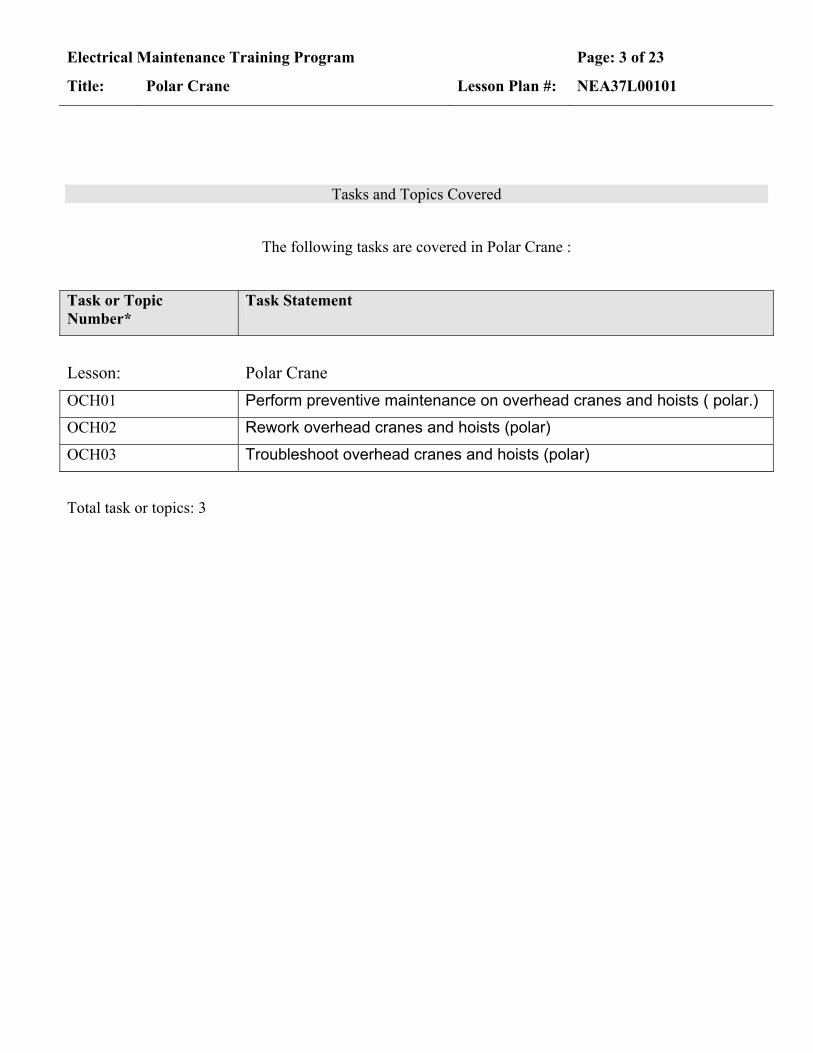
The following tasks are covered in Polar Crane :
Task or Topic Number*
Task Statement
Lesson: Polar Crane OCH01 Perform preventive maintenance on overhead cranes and hoists ( polar.)
OCH02 Rework overhead cranes and hoists (polar)
OCH03 Troubleshoot overhead cranes and hoists (polar)
Total task or topics: 3
Electrical Maintenance Training Program Page: 4 of 23
Title: Polar Crane Lesson Plan #: NEA37L00101
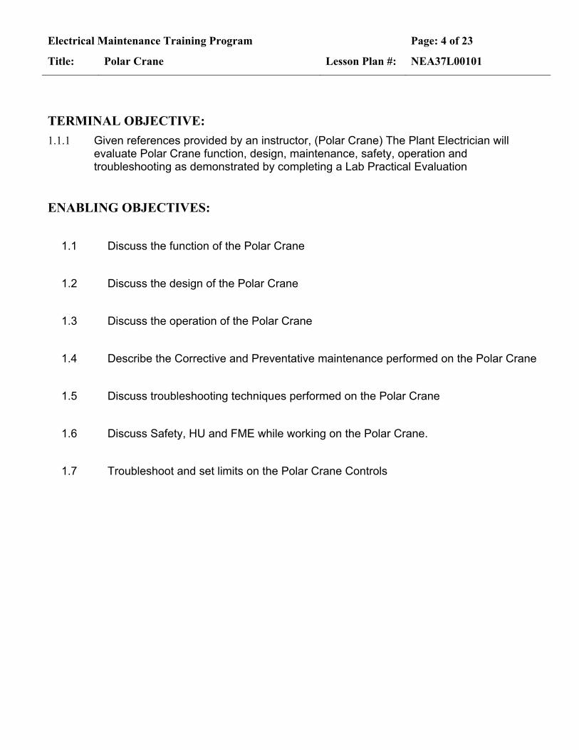
TERMINAL OBJECTIVE:
1.1.1 Given references provided by an instructor, (Polar Crane) The Plant Electrician will evaluate Polar Crane function, design, maintenance, safety, operation and troubleshooting as demonstrated by completing a Lab Practical Evaluation
ENABLING OBJECTIVES:
1.1 Discuss the function of the Polar Crane
1.2 Discuss the design of the Polar Crane
1.3 Discuss the operation of the Polar Crane
1.4 Describe the Corrective and Preventative maintenance performed on the Polar Crane
1.5 Discuss troubleshooting techniques performed on the Polar Crane
1.6 Discuss Safety, HU and FME while working on the Polar Crane.
1.7 Troubleshoot and set limits on the Polar Crane Controls

Electrical Maintenance Training Program Page: 5 of 23
Title: Polar Crane Lesson Plan #: NEA37L00101
TO: 1.1.1 Given references provided by an instructor, (Polar Crane) The Plant Electrician will evaluate Polar Crane function, design, maintenance, safety, operation and troubleshooting as demonstrated by completing a Lab Practical Evaluation
EO: 1.1 Discuss the function of the Polar Crane
LESSON PLAN METHODS AND ACTIVITIES
EO 1.1 Describe the function of the Polar Crane
Design Basis Statement:
• “Overhead crane equipment located in the Containment Building used for handling various loads including radioactive material. Failures may lead to regulatory consequences and unacceptable increased risk in personnel and radiological safety hazards. Some failures are considered hidden since equipment is normally parked and not operating”
See power point to show functions (x)MZCNC02
Typical Function • To perform various lifts and moves in support of
maintenance of containment equipment and to support the disassembly and reassembly of the components necessary for fueling operation.
Loads
• Based on the overall rating of the Polar Crane.
Show power point loads from load cell measurements
Electrical Maintenance Training Program Page: 6 of 23
Title: Polar Crane Lesson Plan #: NEA37L00101
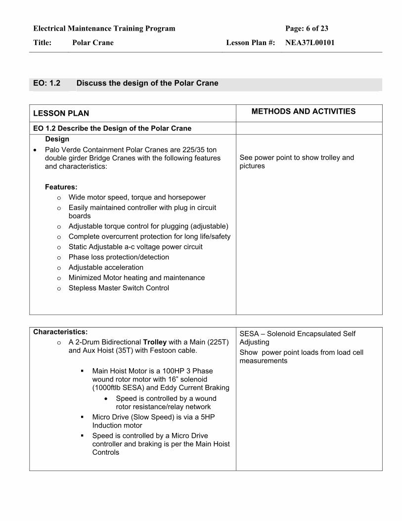
EO: 1.2 Discuss the design of the Polar Crane
LESSON PLAN METHODS AND ACTIVITIES
EO 1.2 Describe the Design of the Polar Crane
Design • Palo Verde Containment Polar Cranes are 225/35 ton
double girder Bridge Cranes with the following features and characteristics:
Features:
o Wide motor speed, torque and horsepower o Easily maintained controller with plug in circuit
boards o Adjustable torque control for plugging (adjustable) o Complete overcurrent protection for long life/safety o Static Adjustable a-c voltage power circuit o Phase loss protection/detection o Adjustable acceleration o Minimized Motor heating and maintenance o Stepless Master Switch Control
See power point to show trolley and pictures
Characteristics: o A 2-Drum Bidirectional Trolley with a Main (225T)
and Aux Hoist (35T) with Festoon cable.
Main Hoist Motor is a 100HP 3 Phase wound rotor motor with 16” solenoid (1000ftlb SESA) and Eddy Current Braking
• Speed is controlled by a wound rotor resistance/relay network
Micro Drive (Slow Speed) is via a 5HP Induction motor
Speed is controlled by a Micro Drive controller and braking is per the Main Hoist Controls
SESA – Solenoid Encapsulated Self Adjusting Show power point loads from load cell measurements

Electrical Maintenance Training Program Page: 7 of 23
Title: Polar Crane Lesson Plan #: NEA37L00101
Aux Hoist Motor is a 75HP 3 Phase wound
rotor motor with 13” SESA (500ftlb SESA) and Eddy Current Braking.
• Speed is controlled by wound rotor resistance/relay network
PP
Trolley Drive Motor is a 15HP 3 Phase wound rotor motor with Solenoid/Shoe brake (140ftlb) and tachometer.
• Speed is controlled by a Primary Thyristor, Reverse plugging controller
• A Tachometer Generator is also used
PP
o A 4 motor Bidirectional double girder Bridge Bridge motors are 20 HP 3 Phase wound
rotor motors with Solenoid brakes. • Speed is controlled by a Primary
Thyristor, Reverse plugging controller
• A operator controlled Hydraulic Brake is also used
Power Point
o Operators Cab: Contains the controls for Main Power,
Lighting, Main and Aux Hoist controls, Bridge and Trolley controls, Trolley and MH limit switch override controls, Brake Bleeder switch, Hydraulic Brake pedal, Dead Man switch and Horn control.
Power Point
Electrical Maintenance Training Program Page: 8 of 23
Title: Polar Crane Lesson Plan #: NEA37L00101
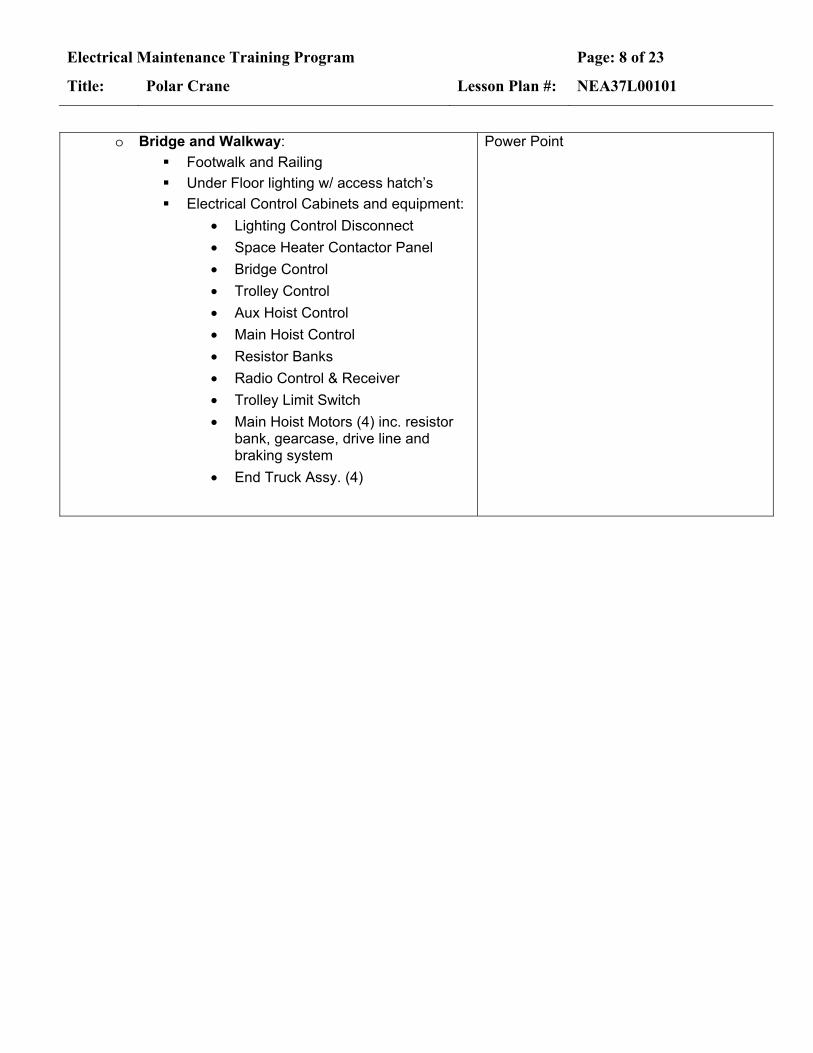
o Bridge and Walkway:
Footwalk and Railing Under Floor lighting w/ access hatch’s Electrical Control Cabinets and equipment:
• Lighting Control Disconnect • Space Heater Contactor Panel • Bridge Control • Trolley Control • Aux Hoist Control • Main Hoist Control • Resistor Banks • Radio Control & Receiver • Trolley Limit Switch • Main Hoist Motors (4) inc. resistor
bank, gearcase, drive line and braking system
• End Truck Assy. (4)
Power Point
Electrical Maintenance Training Program Page: 9 of 23
Title: Polar Crane Lesson Plan #: NEA37L00101
EO: 1.3 Discuss the operation of the Polar Crane
LESSON PLAN METHODS AND ACTIVITIES
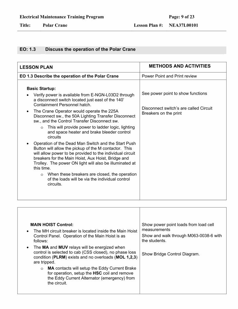
EO 1.3 Describe the operation of the Polar Crane Power Point and Print review Basic Startup:
• Verify power is available from E-NGN-L03D2 through a disconnect switch located just east of the 140’ Containment Personnel hatch.
• The Crane Operator would operate the 225A Disconnect sw., the 50A Lighting Transfer Disconnect sw., and the Control Transfer Disconnect sw.
o This will provide power to ladder logic, lighting and space heater and brake bleeder control circuits
• Operation of the Dead Man Switch and the Start Push Button will allow the pickup of the M contactor. This will allow power to be provided to the individual circuit breakers for the Main Hoist, Aux Hoist, Bridge and Trolley. The power ON light will also be illuminated at this time.
o When these breakers are closed, the operation of the loads will be via the individual control circuits.
See power point to show functions Disconnect switch’s are called Circuit Breakers on the print
MAIN HOIST Control:
• The MH circuit breaker is located inside the Main Hoist Control Panel. Operation of the Main Hoist is as follows:
• The MA and MUV relays will be energized when control is selected to cab (CSS closed), no phase loss condition (PLRM) exists and no overloads (MOL 1,2,3) are tripped.
o MA contacts will setup the Eddy Current Brake for operation, setup the HSC coil and remove the Eddy Current Alternator (emergency) from the circuit.
Show power point loads from load cell measurements Show and walk through M063-0038-6 with the students.
Show Bridge Control Diagram.
Electrical Maintenance Training Program Page: 10 of 23
Title: Polar Crane Lesson Plan #: NEA37L00101
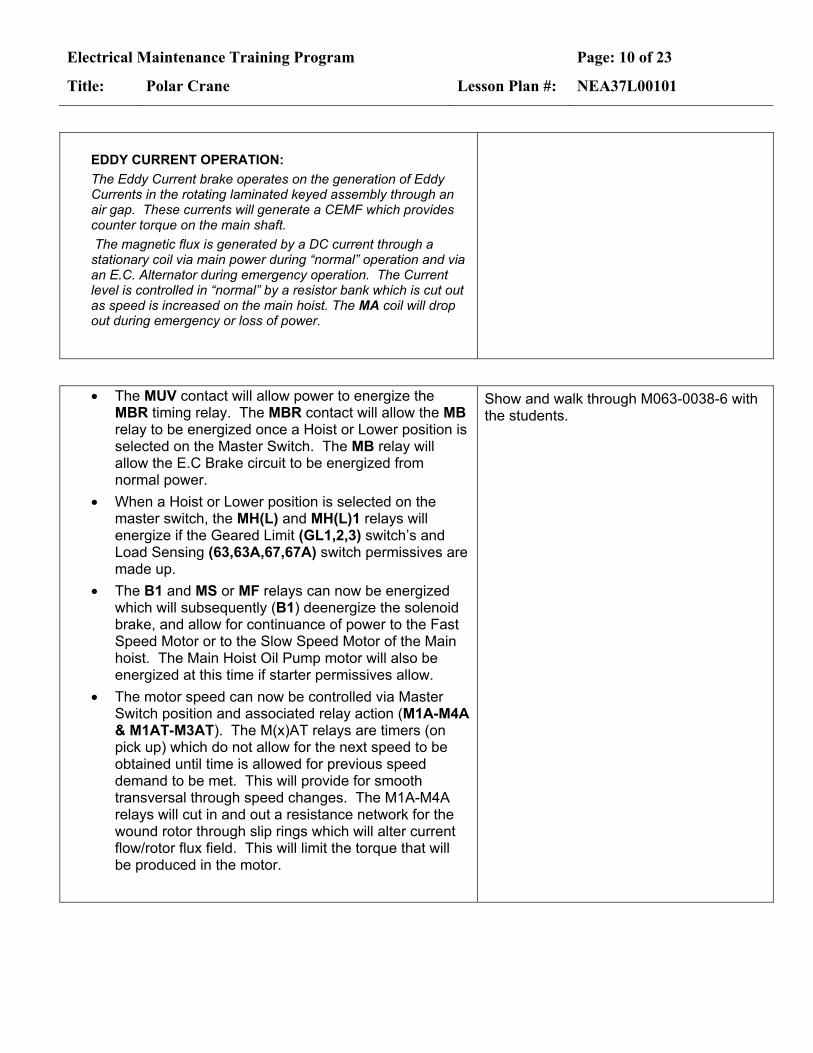
EDDY CURRENT OPERATION: The Eddy Current brake operates on the generation of Eddy Currents in the rotating laminated keyed assembly through an air gap. These currents will generate a CEMF which provides counter torque on the main shaft. The magnetic flux is generated by a DC current through a stationary coil via main power during “normal” operation and via an E.C. Alternator during emergency operation. The Current level is controlled in “normal” by a resistor bank which is cut out as speed is increased on the main hoist. The MA coil will drop out during emergency or loss of power.
• The MUV contact will allow power to energize the MBR timing relay. The MBR contact will allow the MB relay to be energized once a Hoist or Lower position is selected on the Master Switch. The MB relay will allow the E.C Brake circuit to be energized from normal power.
• When a Hoist or Lower position is selected on the master switch, the MH(L) and MH(L)1 relays will energize if the Geared Limit (GL1,2,3) switch’s and Load Sensing (63,63A,67,67A) switch permissives are made up.
• The B1 and MS or MF relays can now be energized which will subsequently (B1) deenergize the solenoid brake, and allow for continuance of power to the Fast Speed Motor or to the Slow Speed Motor of the Main hoist. The Main Hoist Oil Pump motor will also be energized at this time if starter permissives allow.
• The motor speed can now be controlled via Master Switch position and associated relay action (M1A-M4A & M1AT-M3AT). The M(x)AT relays are timers (on pick up) which do not allow for the next speed to be obtained until time is allowed for previous speed demand to be met. This will provide for smooth transversal through speed changes. The M1A-M4A relays will cut in and out a resistance network for the wound rotor through slip rings which will alter current flow/rotor flux field. This will limit the torque that will be produced in the motor.
Show and walk through M063-0038-6 with the students.

Electrical Maintenance Training Program Page: 11 of 23
Title: Polar Crane Lesson Plan #: NEA37L00101
Trolley Control:
• The Trolley motor function is controlled by a A-C Primary Thyristor (SCR) Reverse Plugging Crane Control System. This system controls 2 phases of motor voltage. Along with the control system, a wound rotor motor with fixed 30% slip resistors is used. A Tach Generator is used as feedback control. A stepless Master Switch is used to control the speed/operator demand.
Show Trolley Elementary
Basic Operation:
• Input 3Phase AC line voltage (480Vac) feeds the Trolley Motor through a MCB and Thryristor-Controlled adjustable power circuit. This circuit is designed to control the voltage to the motor from 0 to full voltage for varied torque.
• When the Master Switch is moved out of neutral to
the FWD (F) or REV (R) position, the associated F or R relays will pick up if Fwd or Rev limit switch logic is maintained.
o The CR relay will also pick up and disengage the brakes
• Power is now routed through the Thryristor-
Controlled adjustable AC power source. The power on 2 of the 3 legs is adjusted by time dependant firing of the Thyristors and this power is sent directly to the primary/stator of the 3-phase ac motor. The motor secondary (rotor) has “fixed slip” resistors which maintain a slip value of 30%
Show Trolley Elementary
• The Comparator Board compares the Master Switch Position signal (typ 0 to +/-19Vdc) with the Tach Generator input (Feedback) signal. It will then send an error output to the Current Detector and Firing Circuits.
Internal circuits include:
• Time rate control circuit allows for a rate of change of the Ref Input signal to output signal to be limited to 1 to 10 seconds. (adjustable P3)
Show Trolley Elementary
Electrical Maintenance Training Program Page: 12 of 23
Title: Polar Crane Lesson Plan #: NEA37L00101
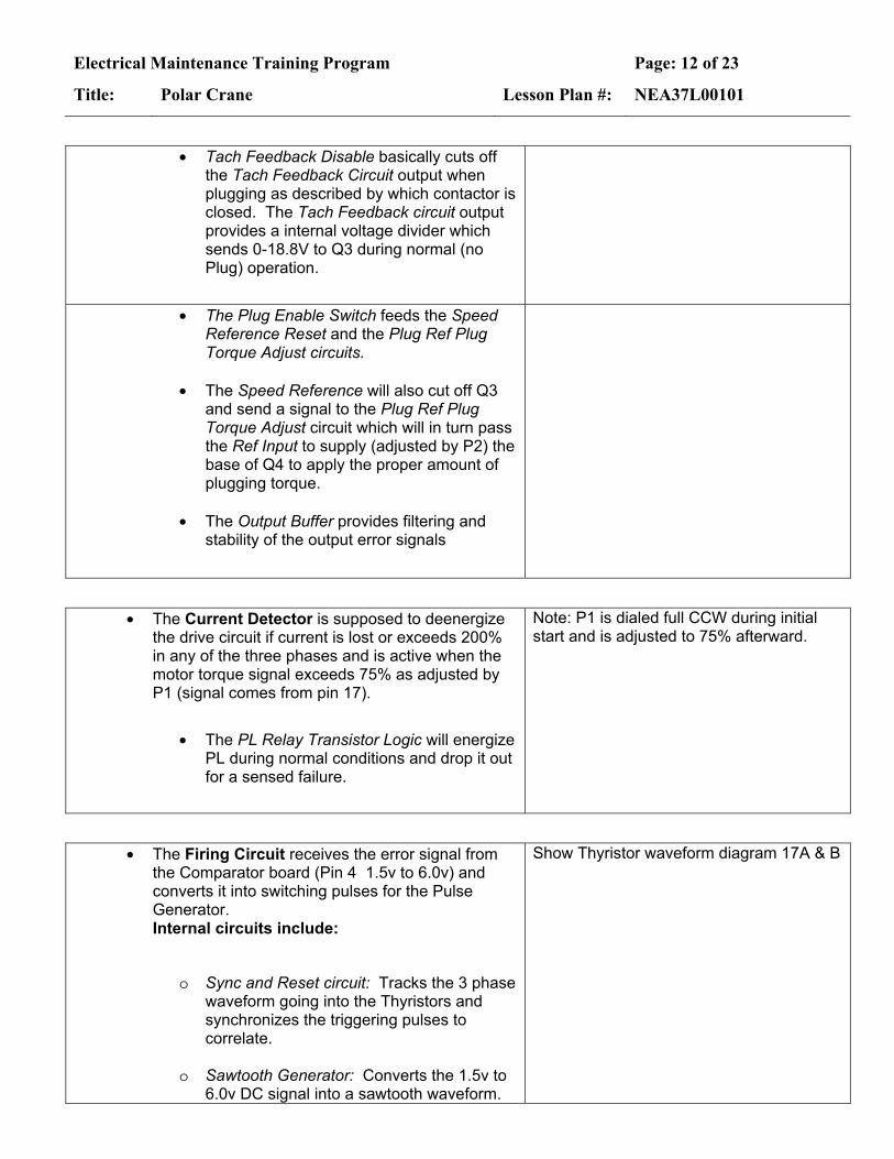
• Tach Feedback Disable basically cuts off the Tach Feedback Circuit output when plugging as described by which contactor is closed. The Tach Feedback circuit output provides a internal voltage divider which sends 0-18.8V to Q3 during normal (no Plug) operation.
• The Plug Enable Switch feeds the Speed Reference Reset and the Plug Ref Plug Torque Adjust circuits.
• The Speed Reference will also cut off Q3
and send a signal to the Plug Ref Plug Torque Adjust circuit which will in turn pass the Ref Input to supply (adjusted by P2) the base of Q4 to apply the proper amount of plugging torque.
• The Output Buffer provides filtering and
stability of the output error signals
• The Current Detector is supposed to deenergize the drive circuit if current is lost or exceeds 200% in any of the three phases and is active when the motor torque signal exceeds 75% as adjusted by P1 (signal comes from pin 17).
• The PL Relay Transistor Logic will energize PL during normal conditions and drop it out for a sensed failure.
Note: P1 is dialed full CCW during initial start and is adjusted to 75% afterward.
• The Firing Circuit receives the error signal from the Comparator board (Pin 4 1.5v to 6.0v) and converts it into switching pulses for the Pulse Generator. Internal circuits include:
o Sync and Reset circuit: Tracks the 3 phase waveform going into the Thyristors and synchronizes the triggering pulses to correlate.
o Sawtooth Generator: Converts the 1.5v to
6.0v DC signal into a sawtooth waveform.
Show Thyristor waveform diagram 17A & B
Electrical Maintenance Training Program Page: 13 of 23
Title: Polar Crane Lesson Plan #: NEA37L00101
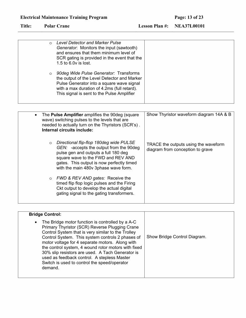
o Level Detector and Marker Pulse
Generator: Monitors the input (sawtooth) and ensures that them minimum level of SCR gating is provided in the event that the 1.5 to 6.0v is lost.
o 90deg Wide Pulse Generator: Transforms
the output of the Level Detector and Marker Pulse Generator into a square wave signal with a max duration of 4.2ms (full retard). This signal is sent to the Pulse Amplifier
• The Pulse Amplifier amplifies the 90deg (square wave) switching pulses to the levels that are needed to actually turn on the Thyristors (SCR’s) . Internal circuits include:
o Directional flip-flop 180deg wide PULSE
GEN: -accepts the output from the 90deg pulse gen and outputs a full 180 deg square wave to the FWD and REV AND gates. This output is now perfectly timed with the main 480v 3phase wave form.
o FWD & REV AND gates: Receive the
timed flip flop logic pulses and the Firing Ckt output to develop the actual digital gating signal to the gating transformers.
Show Thyristor waveform diagram 14A & B
TRACE the outputs using the waveform diagram from conception to grave
Bridge Control:
• The Bridge motor function is controlled by a A-C Primary Thyristor (SCR) Reverse Plugging Crane Control System that is very similar to the Trolley Control System. This system controls 2 phases of motor voltage for 4 separate motors. Along with the control system, 4 wound rotor motors with fixed 30% slip resistors are used. A Tach Generator is used as feedback control. A stepless Master Switch is used to control the speed/operator demand.
Show Bridge Control Diagram.

Electrical Maintenance Training Program Page: 14 of 23
Title: Polar Crane Lesson Plan #: NEA37L00101
Power Supply Circuit
o Accepts the 480Vac input and provides a filtered 45Vdc, a filtered 33Vdc, 2 - 35Vrms (sync signals) and a common reference point to all of the boards in the logic bucket.
Electrical Maintenance Training Program Page: 15 of 23
Title: Polar Crane Lesson Plan #: NEA37L00101
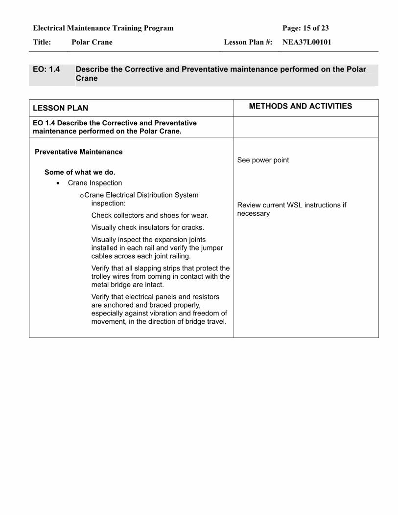
EO: 1.4 Describe the Corrective and Preventative maintenance performed on the Polar Crane
LESSON PLAN METHODS AND ACTIVITIES
EO 1.4 Describe the Corrective and Preventative maintenance performed on the Polar Crane.
Preventative Maintenance
Some of what we do.
• Crane Inspection
o Crane Electrical Distribution System inspection:
Check collectors and shoes for wear.
Visually check insulators for cracks.
Visually inspect the expansion joints installed in each rail and verify the jumper cables across each joint railing.
Verify that all slapping strips that protect the trolley wires from coming in contact with the metal bridge are intact.
Verify that electrical panels and resistors are anchored and braced properly, especially against vibration and freedom of movement, in the direction of bridge travel.
See power point Review current WSL instructions if necessary
Electrical Maintenance Training Program Page: 16 of 23
Title: Polar Crane Lesson Plan #: NEA37L00101
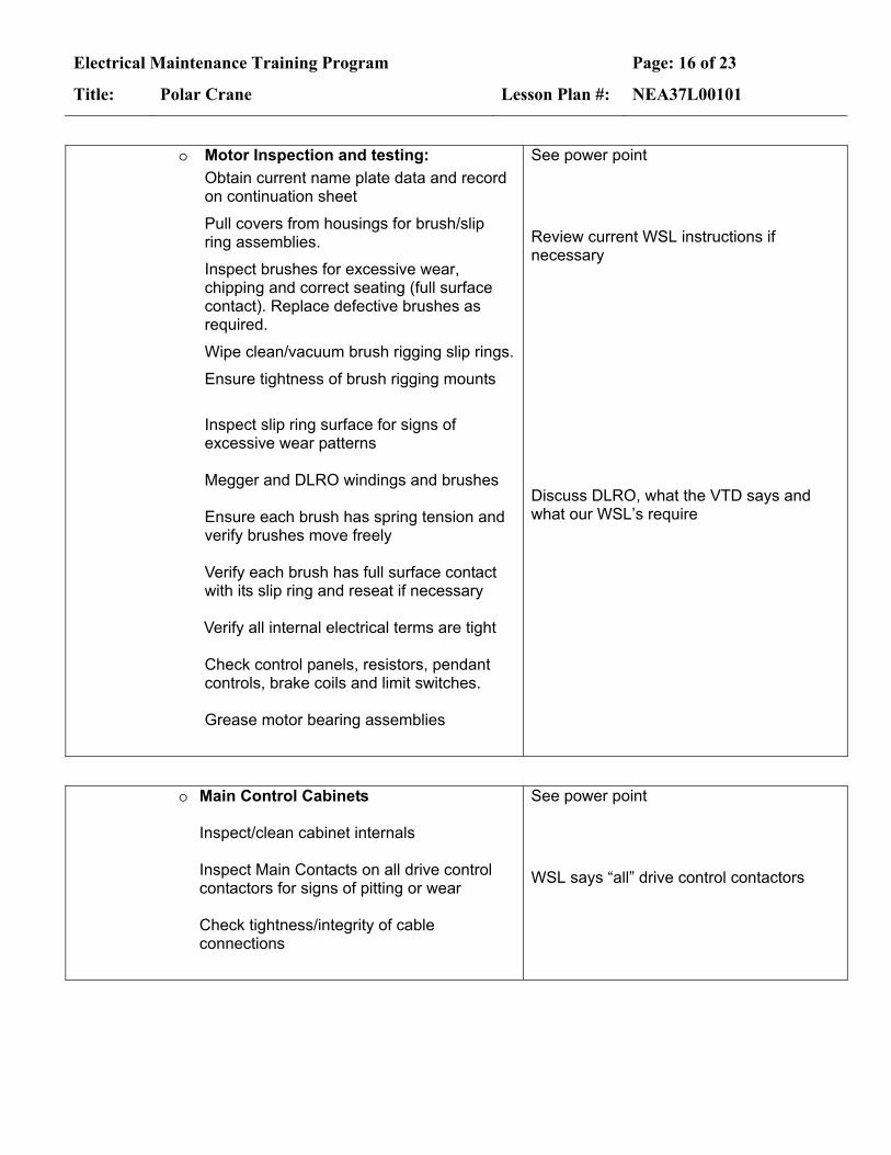
o Motor Inspection and testing:
Obtain current name plate data and record on continuation sheet
Pull covers from housings for brush/slip ring assemblies.
Inspect brushes for excessive wear, chipping and correct seating (full surface contact). Replace defective brushes as required.
Wipe clean/vacuum brush rigging slip rings.
Ensure tightness of brush rigging mounts
Inspect slip ring surface for signs of excessive wear patterns Megger and DLRO windings and brushes Ensure each brush has spring tension and verify brushes move freely Verify each brush has full surface contact with its slip ring and reseat if necessary
Verify all internal electrical terms are tight Check control panels, resistors, pendant controls, brake coils and limit switches. Grease motor bearing assemblies
See power point
Review current WSL instructions if necessary
Discuss DLRO, what the VTD says and what our WSL’s require
o Main Control Cabinets
Inspect/clean cabinet internals Inspect Main Contacts on all drive control contactors for signs of pitting or wear Check tightness/integrity of cable connections
See power point
WSL says “all” drive control contactors

Electrical Maintenance Training Program Page: 17 of 23
Title: Polar Crane Lesson Plan #: NEA37L00101
o Crane Operation Cab
(Space Heaters must be on for 24hrs prior to performing this evolution) Verify that each motor speed controller operates smoothly over the full range Inspect console for signs of damage Verify all indicating lights function Operate the crane hoist, trolley and bridge motors and verify full range operation Verify all stages of speed control operate Monitor motor current of all motors during operation including micro drive. Verify brake operation for release and restriction
See power point
o Inspect and replace Crane Lighting
Energize all Polar Crane Lighting Replace & clean lamps and fixtures as necessary
See power point
o Trolley coasting several feet when the
controller returned to the neutral position – Found the armature for the CR relay was not returning to the deenergized position when power to the coil was removed. An associated contact prevented the brakes from energizing.
o Micro Drive not engaging properly on the Main Hoist – Found the clutch assembly had mal-functioned which caused the clutch housing to rotate and sever the wiring to the coil.
See power point

Electrical Maintenance Training Program Page: 18 of 23
Title: Polar Crane Lesson Plan #: NEA37L00101
o Bridge Drive dropped out repeatedly at initial take off – Found the Phase Loss Relay (PL) was dropping out, adjusted P1 on the current detector to prevent reoccurrence.
o Main Hoist would not lower – Found Main Gear case Oil pump Overloads to be tripped
o Bridge Drive 30% Slip resistors found with decolonization – Found the Bridge was continuously run in slow speeds
o Repeated tripping of the Thermals on the Bridge and Trolley drives – These drives are not designed for long term slow speed operation.
o Trolley drive motor would not run – Found damaged Festoon Cable
o Crane Heavy Load Limit Switch engaged 9 foot lower than the required 18’ limit – Performed geared limit switch adjustment.
o Geared Limit Switch Adjustment – GLS1 set to 18’ above Rx vessel flange, GLS2 High-High cutoff, GLS3 Low-Low Cutoff
o Crane rail travel issues

Electrical Maintenance Training Program Page: 19 of 23
Title: Polar Crane Lesson Plan #: NEA37L00101
EO: 1.5 Discuss troubleshooting techniques performed on the Polar Crane
LESSON PLAN METHODS AND ACTIVITIES
EO 1.5 Discuss troubleshooting techniques performed on the Polar Crane
Troubleshooting Methodology: • To effectively troubleshoot the Polar Crane, you really
need to observe the indications associated with the failure. The crane operator will usually be the best point of reference as to the degree and change of symptoms that are occurring or have occurred.
See power point
Bridge or Trolley Problems: • Ensure power is available (Breakers, Fuses,
Overloads, Deadman etc.) o Fluke 87 checks:
3 phase power at motors Master switch output (0-19V) Tachometer Gen voltage (0-120V) Card signals & gating signals
• Check motor(s) o overheating (often occurs on trolley) o Slip rings and brushes (wear, contamination &
degradation) o Phase imbalance (current and resistance)
• Verify cards (visual, power supply) • Verify Brakes disengage when energized
o Check for shorts or opens (verify resistance) o Verify free movement
• Ensure not in zone limits
Have class discuss prior to showing Power Point

Electrical Maintenance Training Program Page: 20 of 23
Title: Polar Crane Lesson Plan #: NEA37L00101
EO: 1.6 Discuss Safety, HU and FME while working on the Polar Crane.
LESSON PLAN METHODS AND ACTIVITIES
EO 1.6 Discuss Safety, HU and FME while working on the Polar Crane
• Personal Safety Aspects with the Polar Crane
o Energized Equipment – Use 01DP-0IS13 for electrical safety requirements
o Fall Hazards – Fall Protection required when working outside of the walkway (i.e. motor inspect/lube, trolley platform work, etc…)
o Keep hands free when climbing up or down ladders. Articles too large for the pockets or belts should be lifted to or lowered from the crane by a hand line. Take care that loose parts and tools do not fall to the floor beneath. Secure tools and test equipment to the crane if conditions require such action. Do not wear loose or torn clothing which may be caught in the movable parts of the crane.
o During operational verification observe:
Pinch points and crush potentials
Clearance areas (overhead)
tools are secure (dropped items)
See power point

Electrical Maintenance Training Program Page: 21 of 23
Title: Polar Crane Lesson Plan #: NEA37L00101
• Nuclear Safety Aspects with the Polar Crane
o The Polar Crane plays a key role in handling equipment directly associated with the Reactor. Dropped or mishandled components due to a malfunctioning Polar Crane could be detrimental to Nuclear Safety, especially with exposed fuel.
See Power Point
• Radiological Safety Aspects with the Polar Crane o Per the original design statements, the Polar
Crane is used to transport radioactive materialso All work is performed in a CA
o Full Dressout is required
See Power Point
• FME Aspects associated with the Polar Crane
o The Polar Crane is considered a High Risk or Zone III due to the potential work over the Reactor Cavity especially with the Head removed.
o All tools and equipment must be logged into and out of the FMEA
See Power Point

Electrical Maintenance Training Program Page: 22 of 23
Title: Polar Crane Lesson Plan #: NEA37L00101
EO: 1.7 Troubleshoot and set limits on the Polar Crane Controls
LESSON PLAN METHODS AND ACTIVITIES
EO 1.7 Troubleshoot and set limits on the Polar Crane Controls
• Practice:
o Perform Geared Limit Switch adjustments with mockup and verify at least 2 switches operate together after adjustments are made.
o Perform familiarization testing of the Thermistor Voltage control module of the polar crane.
o Perform a lap practical evaluation on:
Troubleshooting scenario (prints)
GLS mockup for 2 switches
Lab Mockup
Electrical Maintenance Training Program Page: 23 of 23
Title: Polar Crane Lesson Plan #: NEA37L00101
SUMMARY OF MAIN PRINCIPLES The following items are things to consider in your lesson summary. They are not mandatory. You should develop your own summary.
Objectives Review Review the Lesson Objectives Topic Review Restate the main principles or ideas covered in the lesson. Relate key points to the objectives. Use a question and answer session with the objectives. Questions and Answers Oral questioning Ask questions that implement the objectives. Discuss student’s answers as needed to ensure the objectives are being met. Problem Areas Review any problem areas discovered during the oral questioning, quiz, or previous tests, if applicable. Use this opportunity to solicit final questions from the students (last chance). Concluding Statement If not done in the previous step, review the motivational points that apply this lesson to students needs. If applicable, end with a statement leading to the next lesson. You may also use this opportunity to address an impending exam or practical exercise. Should be used as a transitional function to tie the relationship of this lesson to the next lesson. Should provide a note of finality.