Palladium Tower Dayanım Gelişimi Kalıp Alma ve Beton Sıcaklığı Bildiri Mayıs 2015
16
1 STRENGTH DEVELOPMENT, FORMWORK REMOVAL AND TEMPERATURE CONTROLLED CASTING OF CONCRETE IN A HIGH-RISE BUILDING Ali Elmaskaya (1) Mehmet Ali Taşdemir (2) (1) Nida Construction & Turism Co, Inc., Istanbul (2) Istanbul Technical University, Istanbul Abstract The three meters deep foundation of the high-rise building studied, called Palladium Tower, was cast in three layers, one meter at a time. The maximum temperature of the mass concrete foundation at the core and the maximum allowable mean temperature of each foundation layer calculated in terms of core, bottom and edge temperatures were 55ºC and 53ºC, respectively. During hardening, the maximum allowable temperature difference between the internal average temperature and the surface temperature measured at the concrete cover depth was less than 20 o C for each layer. The average temperature differences between the layers were also limited to a maximum value of 20ºC. At early ages, a reliable basis for determining the proper formwork removal time was used to prevent cracking of reinforced concrete members. For this purpose, the curing parameters including the time, temperature, the method of placing concrete in the structure and the test specimens, especially cylinders cured on site, as well as the weather conditions were recorded. When formwork was removed, there was no excessive deflection or distortion and no evidence of cracking or other damage to the structural members were observed. Protection of the steel reinforcement against corrosion, due to chloride ion diffusion and/or carbonation, is the most important factor in achieving long service life of the structure. Thus, the concrete cover on the reinforcement was ensured to have enough thickness and strength. For this purpose, special repair techniques were applied to the locally segregated surfaces against corrosion of reinforcements.
-
Upload
ali-elmaskaya -
Category
Documents
-
view
22 -
download
0
Transcript of Palladium Tower Dayanım Gelişimi Kalıp Alma ve Beton Sıcaklığı Bildiri Mayıs 2015

1
STRENGTH DEVELOPMENT, FORMWORK REMOVAL AND
TEMPERATURE CONTROLLED CASTING OF CONCRETE
IN A HIGH-RISE BUILDING
Ali Elmaskaya (1)
Mehmet Ali Taşdemir (2)
(1) Nida Construction & Turism Co, Inc., Istanbul
(2) Istanbul Technical University, Istanbul
Abstract
The three meters deep foundation of the high-rise building studied, called Palladium
Tower, was cast in three layers, one meter at a time. The maximum temperature of the mass
concrete foundation at the core and the maximum allowable mean temperature of each
foundation layer calculated in terms of core, bottom and edge temperatures were 55ºC and
53ºC, respectively. During hardening, the maximum allowable temperature difference
between the internal average temperature and the surface temperature measured at the
concrete cover depth was less than 20oC for each layer. The average temperature differences
between the layers were also limited to a maximum value of 20ºC. At early ages, a reliable
basis for determining the proper formwork removal time was used to prevent cracking of
reinforced concrete members. For this purpose, the curing parameters including the time,
temperature, the method of placing concrete in the structure and the test specimens, especially
cylinders cured on site, as well as the weather conditions were recorded. When formwork was
removed, there was no excessive deflection or distortion and no evidence of cracking or other
damage to the structural members were observed. Protection of the steel reinforcement against
corrosion, due to chloride ion diffusion and/or carbonation, is the most important factor in
achieving long service life of the structure. Thus, the concrete cover on the reinforcement was
ensured to have enough thickness and strength. For this purpose, special repair techniques
were applied to the locally segregated surfaces against corrosion of reinforcements.

2
1. INTRODUCTION
In the design and construction of high rise buildings, high strength concrete is used more
often because element dimensions of these structures are larger compared to those built using
normal strength concrete. However, the heat of hydration of their mass concrete foundations
and the resulting temperature rise in the concrete can cause thermal cracking [1]. It is
commonly thought that mass concrete principles only apply to large dams, but they apply to
any large pours such as massive foundations, bridge piers, thick slabs, nuclear plants, and
some large scale structural columns and shear walls. Therefore, ACI 207 defines mass
concrete as “any volume of concrete with dimensions large enough to require that measures
be taken to cope with generation of heat from hydration of the cement and attendant volume
change to minimize cracking” [2].
The cracking of concrete at early ages can be prevented by controlling its volumetric
consistency during hardening, the time dependent deformations and their variations due to the
temperature differences between the interior and the exterior as well as between the layers, the
element sizes and the pouring order [3-8]. When dimensions are greater than 1m, the
temperature rise should be considered. Since the depth of foundation in Palladium Tower
investigated here is 3m, it meets the definition of mass concrete. The heavy reinforcement in
the foundations of this project does not mean that the concrete will not crack and certainly
will not prevent generation of heat [1]. Results from the literature suggest that the formation
of delayed ettringite is activated when concrete is subjected to elevated temperatures [9-15].
Thus, increased internal temperature due to casting of mass concrete must be considered. For
this purpose, a temperature monitoring method for the deep foundation in this project was
used to minimize the maximum concrete temperatures and temperature differentials, thus
preventing thermal cracking and damage through delayed ettringite formation. In addition to
temperature controlled casting of massive members, strength development of concrete,
formwork removal methods, and repair techniques in the local areas with surface defects were
employed.
2. ABOUT THE PROJECT
Palladium Tower was built in Ataşehir which is a district in the Asian part of Istanbul. Its
construction was completed in 2014. The total construction area in the project is 99.784 m2.
The tower is used as an A+ type office building. The tower consists of 4 basements, ground
floor, and 42 normal floors. The height of the tower is 180 m. The investor was Tahincioğlu
Group and main contractor was Nida Construction Co. In the foundations of the tower,
concrete class was C40/50. However, in the construction of columns, core and shear walls,
and slabs, concrete class of C50/60 was used.
3. EXPERIMENTAL WORK
The Palladium Tower Project required concrete designed for durability, unlike those used
in normal structures. In order not to cause cracks in concrete due to the early age temperature
differences between the interior and the exterior as well as between the layers, cements with
low heat of hydration, but with high strength were utilized.
3
Binders and aggregates with low alkali and reactive silica contents were selected to prevent
undesired alkali-aggregate reactions which can appear after long years. The aggregates used
were continuously tested in batches to ensure that they are clean and have proper shape and
size distribution. In the selection of chemical admixtures, it was aimed to achieve the
consistency between cement and aggregate as well as the consistency of the fresh concrete
within its respective tolerances over time.
The main principle for durability was producing a concrete that was as impermeable and
crack free as much as possible. An impermeable concrete was achieved by using low
water/cement ratio and by keeping the properties of the binding material under control in
order to minimize the capillary pores. As a consequence of the achieved durability targets
through minimization of capillary pores, the concrete strength requirement was automatically
satisfied.
3.1 Cements
Cements used in this study were as follows; CEM I 42.5 R and CEM IV/B-P 32.5 N.
Densities of these cements were 3.16 g/cm3
and 2.86 g/cm3, respectively. Initial and final
setting times of CEM I 42.5 R were 166 and 210 minutes, respectively. These values were
188 and 230 minutes, respectively, for CEM IV/B-P 32.5 R. Additional tests on these
cements verified that their physical, chemical and mechanical properties satisfied the
requirements of TS EN 197 standard.
Heat of hydration of cements at 2, 7 and 28 days, determined according to TS EN 196-8 are
given in Table 1.
Table 1 Heat of hydrations of cements.
Cement
Heat of hydration, cal./g
2 days 7days 28 days
CEM I 42.5 R 71.9 86.1 92.5
CEM IV/B-P 32.5 R 48.0 61.2 66.4
3.2 Aggregates
Particle densities and water absorptions of aggregates used are shown in Table 2. An
aggregate sample containing a fraction of 10-14mm sizes taken from both coarse aggregates
was subjected to the abrasion test in accordance with TS EN 1097-2. After 500 revolutions,
the loss of abrasion was 20.3%, which corresponds to the Los Angeles Abrasion Category of
LA25.
Table 2. Particle densities and water absorptions of aggregates
Aggregate Density, g/cm3 Water absorption,%
Natural sand 2.58 1.6
Limestone fines (0-4mm) 2.74 1.1
Coarse aggregate No. I (5-12mm) 2.73 0.8
Coarse aggregate No. I (12-22mm) 2.75 0.6
4
Petrographic analysis of limestone fines and coarse aggregates taken from the same quarry are
summarized below.
Rock contained similar proportions of cryptocrystalline/micritic and recrystallized/
microcrystalline calcite grains. Texture of the rock was homogeneous. Micritic calcite formed
the matrix of the rock. Grain size of the calcite was generally 0- 0.01 mm. Recrystallized
calcite was middle – large sized, generally 0.02 mm, with a homogenous grain size
distribution. Trace amount of opaque minerals was observed.
Table 3. Crushed Rock Mineralogical Constituents
Mineralogical Constituents (%)
Calcite (Primary, micritic) 45-60
Calcite (Secondary, recrystallized) 40-45
Opaque mineral + Iron oxide 1-1,5
From the ASR point of view, ASTM C 1260 states that if the expansion of mortar bar is
lower than %0.10 the aggregate is considered innocuous, if the range of expansion is
between 0.10% and 0.20%, the aggregate is considered potentially reactive and above %0.20
the aggregate is considered reactive. In natural sand, limestone fines and coarse aggregates
from the same quarry and in coarse aggregates, expansions recorded according to ASTM C
1260 were 0.04% and 0.08%, respectively. As a result, these aggregates can be considered
innocuous, because the expansion values measured according to ASTM C 1260 are less than
0.1%.
3.3 Main concrete mixtures used
In the composition of Mix 1 used for the foundation (i.e., C40/50), cements were as
follows; CEM I 42.5 R: 120 kg/m3 and CEM IV/B-P 32.5 N: 260 kg/m
3 and water /cement
ratio was reduced to 0.40. Densities of these cements were 3,16 and 2,86 g/cm3, respectively.
Thus, the mixture composition was: Total cement: Natural sand: Limestone fines: Coarse
aggregate No.I : Coarse aggregate No.II: Chemical admixture (in plant): Chemical admixture
(in construction site): Water = 1 : 1.251 : 1.017 : 1.880 : 1.271 : 0.019 : 0.004 : 0.40. For this
mixture, the target strength was as follows: ƒtg= ƒck + 1.48 ϭ = 40 + 1.48 x3.55 = 45.3 MPa,
here the 1.48 value corresponds to 93% confidence level in accordance with EN 206.
For cold weather conditions, in the composition of Mix 2 used for columns, walls and slabs
(i.e. C50/60); cements were as follows; CEM I 42.5: 300 kg/m3 and CEM IV/B-P 32.5 N: 120
kg/m3 and water /cement was reduced to 0.36. Thus, the mixture composition was: Total
cement: Natural sand: Limestone fines: Coarse aggregate No.I : Coarse aggregate No.II:
Chemical admixture (in plant): Chemical admixture (in construction site): Water = 1 : 1.040 :
0.793 : 1.990 : 0.531 : 0.022 : 0.004 : 0.40. For this mixture, the target strength was as
follows: ƒtg= ƒck + 1.48 ϭ = 50 + 1.48 x2.51 = 53,7 MPa, here the 1.48 value corresponds to
93% confidence level in accordance with EN 206.
For normal weather conditions, in the composition of Mix 3 used for columns, walls and
slabs (i.e. C50/60); cements were as follows; CEM I 42.5 R: 130 kg/m3 and CEM IV/B-P 32.5
5
N: 290 kg/m3 and water /cement was reduced to 0.37. The other constituents were kept the
same as in Mix 2.
4. TEMPERATURE CONTROLLED CASTING OF FOUNDATION CONCRETE
A maximum temperature difference between the mean temperature of the element and the
temperature in the surface of the element was defined. For this purpose, during hardening, the
maximum allowable temperature difference between the internal average temperature and the
surface temperature measured at the concrete cover depth was required to be less than 20oC.
The maximum temperature of the mass concrete foundation was 55oC at the central part of the
third layer of the foundation. During the three consecutive concrete castings of the
foundation, interlayer differences in temperature were also restrained at 20ºC and the targeted
limit values were not exceeded.
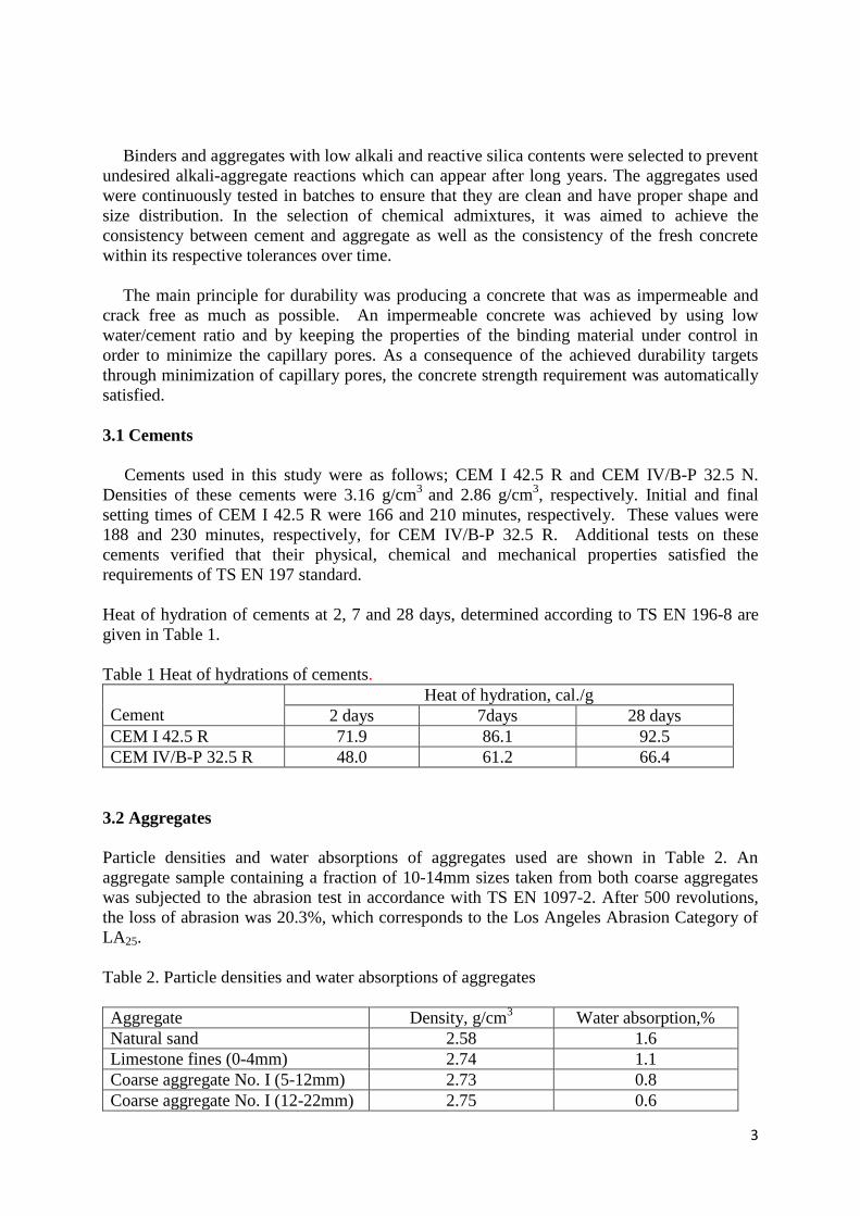
As seen in Figure 1, the three meters deep foundation of the high-rise building studied was
cast in three layers, one meter at a time. Before casting of the mat foundation, three trial
concretes of 1 m3 volume were prepared. Based on the temperature-time curves and strength
developments of these concretes, in accordance with the targeted principles, temperature
controlled casting that also comply with the design strength requirement was accomplished.
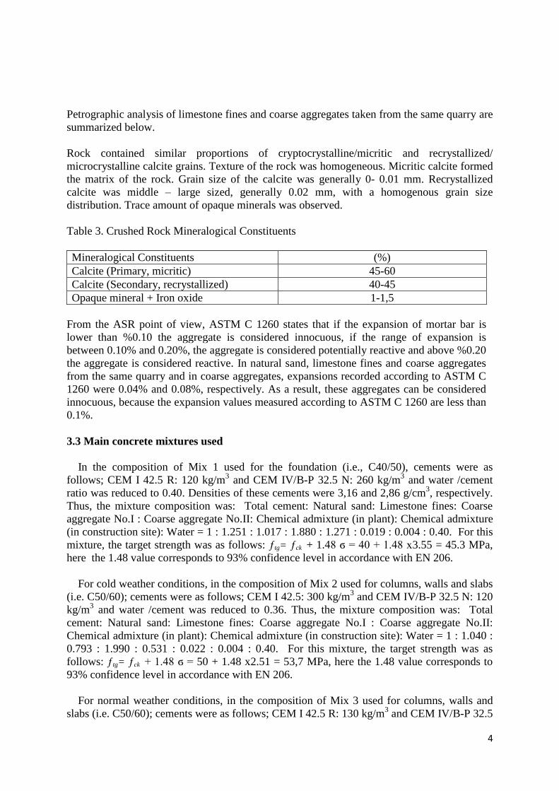
The average internal temperature (Tave) was calculated as:
Tave = (2/3)Tc + (1/6) Tb + (1/6) Te (1)
where Tc, Tb and Te are the temperatures at the center (core), bottom and midpoint of layer
edge, respectively. Ts in Figure 2 is the temperature at the concrete cover depth (i.e. 2-3cm).
Fig.1 Cross-section of the foundation cast in three layers
6
Fig.2 Typical average temperature-time and surface temperature-time curves for the first layer
of the foundation.
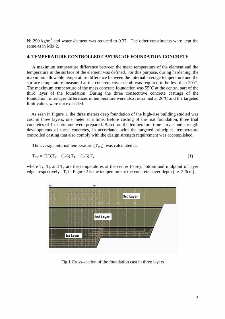
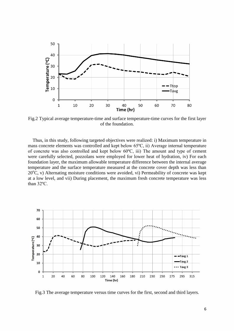
Thus, in this study, following targeted objectives were realized: i) Maximum temperature in
mass concrete elements was controlled and kept below 65ºC, ii) Average internal temperature
of concrete was also controlled and kept below 60ºC, iii) The amount and type of cement
were carefully selected, pozzolans were employed for lower heat of hydration, iv) For each
foundation layer, the maximum allowable temperature difference between the internal average
temperature and the surface temperature measured at the concrete cover depth was less than
20oC, v) Alternating moisture conditions were avoided, vi) Permeability of concrete was kept
at a low level, and vii) During placement, the maximum fresh concrete temperature was less
than 32ºC.
Fig.3 The average temperature versus time curves for the first, second and third layers.
7
5. STRENGTH DEVELOPMENT OF CONCRETE AND REMOVAL OF
FORMWORK
For the vertical R/C elements, there are several factors affecting lateral pressure on the
formwork. They can be summarized as follows: the vertical formwork height, rate of
placement, materials of formwork, vibrator's power, vibration immersion length, mix design
(water/binder, fine aggregate/coarse aggregate, paste volume, binder content, binder type,
supplementary cementitious materials and filler, chemical admixtures), rheology of concrete,
concrete temperature, amount and location of reinforcement, concrete slump, unit weight of
concrete, size and shape of formwork, and maximum aggregate size.
5.1 Strength development
In this study, the strength development of concrete in R/C structures was investigated for
timely removal of the formwork. For this purpose, separate test specimens that were cured on
site were kept in the environment of the construction site. It is clear that curing conditions of
these specimens were different from those cured under standard laboratory conditions to
evaluate the 28-day strength of concrete. For determining the suitable formwork removal
time, the curing parameters including the time, temperature, the method of placing concrete in
the structure and the test specimens, as well as the weather conditions were recorded.
For the strength development of concrete, the relation between age and compressive
strength can be written as follows:
( ) , (2)
where, t is the age of concrete (days) , a and b are coefficients of the equation in dimensions
of MPa ve MPa/log(days). In this equation, the value of constant a can be considered as the
level of strength at one day of age, and b shows the slope of the line in the strength versus
log(t) in the relation.
The relation in Eq. (2) includes the combined effects of weather temperature and the type
of cement. It is clear that besides the type of cement used and the ambient temperature, there
are several factors affecting the strength of concrete such as mix composition, aggregate type,
and curing time.
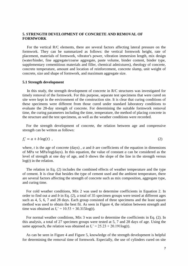
For cold weather conditions, Mix 2 was used to determine coefficients in Equation 2. In
order to find out a and b in Eq. (2), a total of 35 specimen groups were tested at different ages
such as 4, 5, 6, 7 and 28 days. Each group consisted of three specimens and the least square
method was used to obtain the best fit. As seen in Figure 4, the relation between strength and
time was obtained as fc’ = 10.53 + 30.315log(t).
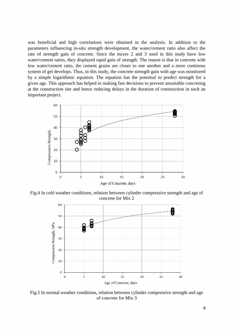
For normal weather conditions, Mix 3 was used to determine the coefficients in Eq. (2). In
this analysis, a total of 27 specimen groups were tested at 5, 7 and 28 days of age. Using the
same approach, the relation was obtained as fc’ = 25.23 + 20.191log(t).
As can be seen in Figure 4 and Figure 5, knowledge of the strength development is helpful
for determining the removal time of formwork. Especially, the use of cylinders cured on site
8
was beneficial and high correlations were obtained in the analysis. In addition to the
parameters influencing in-situ strength development, the water/cement ratio also affect the
rate of strength gain of concrete. Since the mixes 2 and 3 used in this study have low
water/cement ratios, they displayed rapid gain of strength. The reason is that in concrete with
low water/cement ratio, the cement grains are closer to one another and a more continous
system of gel develops. Thus, in this study, the concrete strength gain with age was monitored
by a simple logarithmic equation. The equation has the potential to predict strength for a
given age. This approach has helped in making fast decisions to prevent unsuitable concreting
at the construction site and hence reducing delays in the duration of construction in such an
important project.
Fig.4 In cold weather conditions, relation between cylinder compressive strength and age of
concrete for Mix 2
Fig.5 In normal weather conditions, relation between cylinder compressive strength and age
of concrete for Mix 3
9
5.2 Removal of formwork
At early ages, a reliable basis for determining the proper formwork removal time was
necessary to prevent the damage to the structure. When formwork was removed, there was no
excessive deflection or distortion and no evidence of cracking or other damage to the R/C
structure was observed.
Factors affecting the formwork removal time are the position of the forms, the loads
coming on the R/C members after stripping, the ambient temperature, and subsequent loads
on the member.
The time of formwork removal was based on the strength gain of the cylinder specimens
cured on site. For the evaluation of formwork removal, weather conditions were recorded and
used in conjunction with the cylinder test results. The formwork removal times were
increased if low temperatures were recorded. Early removal of formworks was desirable for
completing construction on time and was usually desirable for curing. Formwork of the
vertical elements such as shear walls, columns and also beam sides were removed without
damage to concrete surfaces and edges. For, the vertical R/C members, the compressive
strength of concrete cube specimens kept at construction site was approximately 10 MPa prior
to the formwork removal. Thus, forms and supports were removed without any impact and
load eccentricity.
The forms of the horizontal R/C members such as beams and slabs were removed carefully
when the compressive strength was equal to or greater than a minimum of 75 percent of the
specified design compressive strength. Therefore, re-shoring was one of the most critical
operations in the construction of slabs in this type of multistory building. Special attention
was paid on removal of forms and shores. Necessary re-shoring was used to support
combined dead and construction loads, thus sufficient load carrying capacity was provided for
each slab. During re-shoring, construction loads were not permitted on the newly constructed
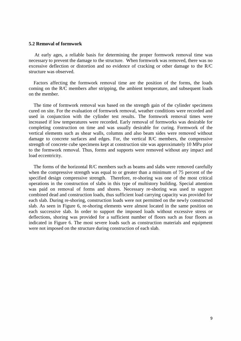
slab. As seen in Figure 6, re-shoring elements were almost located in the same position on
each successive slab. In order to support the imposed loads without excessive stress or
deflections, shoring was provided for a sufficient number of floors such as four floors as
indicated in Figure 6. The most severe loads such as construction materials and equipment
were not imposed on the structure during construction of each slab.
10
Fig.6 A typical example showing shores and re-shores for the high rise building studied.
It is known that a minimum curing period of seven days is recommended for all exposure
classifications. The vertical R/C elements such as column and shear walls were maintained in
sufficiently moist condition using curing compounds. For both vertical elements and slabs,
depending on the climatic condition, water sprays, water retaining techniques such as
polyethylene sheets or insulating blankets were used.
Since the main cause of cracking in R/C elements is insufficient ambient temperature
required for early age strength gain, special measures were taken to maintain and
systematically check the weather conditions during the casting and curing of the R/C
elements. It was essential to make an evaluation of whether the temperature conditions were
sufficient for early strength gain in order to find the correct removal time for the R/C
elements, or to modify the temperature conditions of the construction site to comply with the
required temperature for early formwork removal.
6. CORRECTION OF DEFECTS IN NEWLY HARDENED CONCRETE
When constructing a structure, the stages that should be implemented can be summarized
as follows: 1º) The preparation of the project documents which also include the design that
has been made according to the present soil and environmental conditions as well as the
earthquake performance calculations, 2º) selection of materials that are suitable for the
objectives of the project, 3º) assembly and workmanship, 4º) inspection and auditing, and 5º)
repair works. As mentioned here, repair work is an indispensable part of the project,
therefore, it should be properly applied to the defective areas.
Steps for repairing the local areas of surface defects can be summarized as follows: i) The
boundary of each defective area to be repaired was outlined. ii) In order to remove loose
particles, the area was cut and chipped to create a rough surface for proper bonding of the
repair cement based mixture. For chipping a small electric chipping hammer was used. iii)
The feather edges as indicated in Figure 7 were not allowed. As seen in this figure, the first

11
one (Fig.7a) is incorrect and the second one (Fig. 7b) is correct. iv) The dust and debris in the
area to be repaired were removed, since a well-prepared area should allow the new repair
material to have a suitable surface for good bonding. v) All surfaces to be repaired were
dampened for good bonding, however ponding of the area was not allowed. vi) The repair
material was prepared to fill in the area that was chipped. vii) Although it was necessary to
follow the manufacturer’s instructions, for strong bonding an epoxy with two components
was chosen (Figure 8). viii) The repair mortar was placed into or on the patch location, and
force was applied to get a repair material without air bubbles. ix) The surface of the repair
material was leveled using a trowel, leaving the repaired area slightly higher than the adjacent
edges to allow for setting and shrinkage. x) The area was trowelled with a steel finishing
trowel when the patch material has become stiff (Figure 9). xi) After another hour or two
allowed for setting and initiation of hardening, final finish was applied through trowelling.
During these stages, it was necessary to splash a little water on the surface to retard the
drying, also to make the finishing process somewhat easier. The repaired area was kept wet
for a few days, it was protected from direct sunlight. Protection was also necessary in cold
and hot weather conditions. xii) The repaired surface was ground slightly after one week, until
uniform color was obtained (Figure 10).
(a) Incorrect (b) Correct
Fig.7 Edges to repairs, the saw cut should be used to avoid feather edges.
Fig.8 Application of epoxy using a brush Fig.9. Repair mortar was applied to locally
(For strong bonding, an epoxy with two defective concrete surface
components is suggested)

12
Fig.10 Slight grinding after one week, nearly uniform color was achieved
Protection of the steel reinforcement against corrosion, due to chloride ion diffusion and/or
carbonation, is the most important factor in achieving long service life of the structure. Thus,
the concrete cover on the reinforcement bar was ensured to have enough thickness and
strength. Eventually, in order to ensure sufficient strength gain at early ages, sufficient curing
was applied and the hardening period was closely followed.
As typically observed, there were some voids like “bird eyes” on the surfaces of the R/C
elements. These voids, also called bug holes, are small regular or irregular cavities, usually
not exceeding 10 mm in size, resulting from entrapment of air bubbles on the surface of cast
concrete during placement and consolidation. The number of such voids in a concrete surface
of 1 m2 was less than 50, this limitation was also used in several specifications. In this study,
the following key factors were also considered to minimize these voids and to improve the
surface quality of concrete: i) mold release agent, ii) free water in concrete, iii) air, iv)
condition of formwork, v) vibration, vi) maximum aggregate size, combined aggregate
grading and coarse aggregate shape, vii) consistency of concrete, and vii) rate of concrete
casting.
7. QUALITY CONTROL OF CONCRETE
Quality control of concrete started with the inspection of aggregate, cement, water and
additives. It continued with the measurement of properties in the fresh and hardened state of
concrete formed by these constituents. Continuous inspection of concrete from a production
plant was performed through standard cylinder compressive strength tests on samples taken at
the plant and at the job site where acceptance criteria were applied for each concrete batch.
The results obtained by the inspection company were evaluated through standard
requirements. Therefore, the quality control of concrete consisted of the following processes:
i) Mix design (calculation of the amounts of materials that constitute concrete), ii) Production,
iii) Sampling, storing and curing, iv) statistical evaluation and application of acceptance
criteria.
In this project, high quality concrete required in the project specification was obtained
through proper production, placing, and curing. For these purposes, implemented steps were

13
as follows: selection of the right materials for the purpose, use of high quality materials,
proper composition and mixture of materials including water, proper placing and compaction
with minimum bleeding, proper concrete curing for desired maturity, and prevention of high
temperatures and temperature gradients within concrete in the initial hardening period.
For C50/60 concrete cylinder compression test results that follow normal (Gaussian)
distribution, if the mean compressive strength is fcm, the characteristic strength (fck) can be
calculated as follows: ƒck = ƒcm – 1.48 ϭ ≥ ƒcd. In the expression for the characteristic strength,
the 1.48 value corresponds to 93% confidence level in accordance with EN 206.
Control cards were used to inspect the compressive strength of concrete. Horizontal axis of
these cards may be time, production unit or the unit of the inspected property. Vertical axis
shows the arithmetic average of the production unit, warning and action limits. In this project,
the design concrete strength was 50 MPa and 95% confidence level was specified. For this
concrete class, since the standard deviation was 2.51 MPa, the target strength (fct) can be
calculated as follows: ƒct = ƒcd + z0.05 .ϭ = 50 + 1.64x2.51 = 54.1 MPa, where 0.05z is the value
of the standard normal variable that corresponds to 95% confidence level. The average
strength of 286 groups was 54.14 MPa, which is identical to the target strength (54.14 MPa).
The target strength for the 93% confidence level, however, was calculated as ƒct = 50 +
1.48x2.51 = 53.7MPa. In this case, the average strength is greater than the target strength
calculated according to the 93% confidence level.
Therefore, the top and bottom limits corresponding to 95% confidence level were 56.4 MPa
and 51.7 MPa, respectively. These values are the action (production termination) limits. In
addition, the top and bottom limits corresponding to 90% confidence level for the strength of
batches were calculated as 52.2 and 56.0 MPa, respectively. These are, however, warning
limits for the production of concrete.
The production chart obtained in this study has shown that the course of production was
good. The results mostly did not fall outside the action (production termination) limits and
they have shown an approximately balanced distribution around the mean. Similar results
were also obtained for the foundation concrete (i.e., C40/50).
7. CONCLUSIONS
Based on the results obtained in this study, the following conclusions can be drawn:
1) The three meters deep concrete foundation of the tower was cast in three equal layers.
In the first, second and third layers, the maximum temperatures recorded were 45ºC,
51ºC and 55ºC, respectively. For these layers, however, the maximum average internal
temperatures were 41ºC, 51ºC, and 53ºC, respectively. The internal average
temperature differences between the layers were below or equal to 20ºC. For the first,
second and third layers, the temperature differences between the internal average
temperature and the surface temperature at the concrete cover depth were 14ºC, 17ºC
and 18ºC, respectively. Thus, during casting of the concrete foundations, maximum
temperatures and the temperature differences between interior-exterior and between-
layers were restrained and the specified limit values were not exceeded.

14
2) For determining a suitable formwork removal time for the slabs, separate test
specimens were cast and cured on-site, exposed to the environment of the construction
site. These specimens were different compared to those cured under standard
laboratory conditions to evaluate the 28-day strength of concrete. Since the early
removal of formwok was desired, the use of a logarithmic type of relation for the
strength development was beneficial. In addition, the curing parameters including the
time, temperature, the method of placing concrete in the structure and the test
specimens, and the weather conditions were recorded.
3) The forms of beams and slabs were removed carefully when the compressive strength
was equal to or greater than a minimum of 75 percent of the design compressive
strength. Necessary re-shoring was used to support combined dead and construction
loads. Shoring was provided for a sufficient number of floors such as three or four
floors without any early age cracking due to excessive deflections. During re-shoring,
construction loads were not permitted on the newly constructed slab. During
formwork removal, there was no excessive deflection or distortion and no evidence of
cracking or other damage was observed to the structural member.
4) Formwork of the vertical elements such as shear walls, columns and also beam sides
were removed without damage to concrete surfaces and edges. At the construction
climatic conditions, about 10MPa cube compressive strength prior to the formwork
removal was sufficient for the vertical elements mentioned. Thus, forms and supports
were removed without any impact and load eccentricity.
5) Since the thickness and strength of the concrete cover play important roles in the long
term performance of an R/C element, the repair work was applied to the defective
surface areas as an indispensable part of the construction. Especially, for the locally
segregated surface areas, a special patching technique was employed as a protective
measure against future corrosion of reinforcements.
6) Mean concrete compressive strength was greater than the target strengths calculated
according to both 93% and 95% confidence levels for each concrete class (i.e. C40
and C50). The production charts used in this study showed that the results mostly did
not fall outside the action (production termination) limits and they have shown an
approximately balanced distribution around the target strengths.
ACKNOWLEDGEMENT
The authors acknowledge Mr. Mustafa Adnan Öğüt - Emir Engineering Ltd., for his
encouragements to write this paper, who is the structural designer of the Palladium Tower
Project.
15
REFERENCES
[1] Whittier, S., Olyniec, J., and McGlohn, R., “Minimizing Temperature Differentials in
Mass Concrete”, Concrete International, Dec., 2014, pp. 43-45.
[2] ACI Committee 207, “Mass Concrete – 207. 1R-96” ACI, 1996.
[3] “Temperature control of mass concrete”, in EM 1110-2-2200, US Army Corps of
Engineers Publications, 1995.
[4] Elmaskaya, A. ve Taşdemir, M.A., “Temperature Controlled Casting and Strength
Development of the Deep Foundation Concrete of Palladium Tower Project”, 21-23
February 2013, Proceedings of RMCO of Turkey 2013, pp. 366 – 381(in Turkish
with English summary).
[5] Yetiş S., Kaya A. ve Taşdemir, M. A., “Temperature Controlled Concrete Casting in
Foundations of Porta Batumi Tower, Strength Development, Removal Times of
Formwork and Surface Properties of Concrete”, Proceedings of 9th National Concrete
Congress, Antalya, 16-18 April 2015, pp.503-516 (in Turkish).
[6] Taşdemir, M.A., Akkaya, Y., Erdoğdu, S., and Ozturk, M., “Quality Assurance for
the Deepest Immersed Tube Tunnel: Marmaray Project”, Advances in Concrete :
An Asian Perspective, ACECON 2010, Eds. R. Gettu et al., 2010, pp. 252-267.
[7] Taşdemir M.A. and Akkaya, Y., “Turkey - Concrete Construction Industry -
Cement Based Materials and Civil Infrasturucture - (CBM-CI)”, CBM-CI
International Workshop, Ed. S. Ahmad, Karachi, 2007, pp. 185-200.
[8] Akkaya, Y. and Taşdemir, M.A., “Turkish Experience in Concrete Construction
Industry and Infrasturucture”, UNESCO-IPRED-ITU Workshop, 6-7 July 2009, pp.
159-164.
[9] Stark, J., Bollmann, K., “Delayed Ettringite Formation in Concrete”, Nordic
Concrete Research, (23)2, pp. 1-25, 1999.
[10] Collepardi, M., “A State-of-the-Art Review on Delayed Ettringite Attack on
Concrete”, Cement and Concrete Composites, 25, pp. 401-407, 2003.
[11] Akman, M. S., “Gecikmiş Etrenjit Oluşumu (DEF)”, 5. Ulusal Beton Kongresi, 1-
3 Ekim, İstanbul, s.9-15, 2003.
[12] Divet, J., and Randriambololona, “Delayed Ettringite Formation: the Effect of
Temperature and Basicity on the Interaction of Sulphate and C-S-H Phase”, Cement
and Concrete Research, 25, No. 3, pp. 357-363, 1998.
[13] Heinz, D., and Ludwig, U., “Mechanisms of Secondary Ettringite Formation in
Mortars and Concretes Subjected to Heat Treatment”, Katharine and Bryant
Mather International Conference, J.M. Scanlons, ed., ACI, Detroit, 1987.
16
[14] Lawrence, C.D., “Mortar Expansions Due to Delayed Ettringite Formation: Effects
of Curing Period and Temperature”, Cement and Concrete Research, 25, No. 4,
pp. 903-914, 1995.
[15] Zhaozhou, Z., Olek, J., and Diamond, S., “Studies on Delayed Ettringite Formation
in Heat-Cured Mortars II. Characteristics of Cement that maybe Susceptible to
DEF”, Cement and Concrete Research, 32, pp. 1737-1742, 2002.