
PAKCK: Power Analysis of Key Computational...
28
Albert Reuther Computing and Analytics Group Suite of Embedded Applications and Kernels (SEAK) Workshop at DAC 2014 1 June 2014 PAKCK: Power Analysis of Key Computational Kernels DARPA MTO PM: Dr. Joseph Cross This work is sponsored by the Defense Advanced Research Projects Agency under Air Force Contract FA8721-05-C-0002. The U.S. Government is authorized to reproduce and distribute reprints for Governmental purposes notwithstanding any copyright annotation thereon. Disclaimer: The views and conclusions contained herein are those of the authors and should not be interpreted as necessarily representing the official policies or endorsements, either expressed or implied, of DARPA or the U.S. Government.
Transcript of PAKCK: Power Analysis of Key Computational...

Albert Reuther Computing and Analytics Group
Suite of Embedded Applications and Kernels (SEAK) Workshop at DAC 2014
1 June 2014
PAKCK: Power Analysis of Key Computational Kernels
DARPA MTO PM: Dr. Joseph Cross
This work is sponsored by the Defense Advanced Research Projects Agency under Air Force Contract FA8721-05-C-0002. The U.S. Government is authorized to reproduce and distribute reprints for Governmental purposes notwithstanding any copyright annotation thereon.
Disclaimer: The views and conclusions contained herein are those of the authors and should not be interpreted as necessarily representing the official policies or endorsements, either expressed or implied, of DARPA or the U.S. Government.
PAKCK Benchmarking - 2 AIR 1-June-2014
• Introduction
• Key Computational Kernels and Computational Architectures
• Results
• Exploration of Possible using LLMORE Simulator
• Other Key Benchmark Suites
• Summary and Future Work
Outline
PAKCK Benchmarking - 3 AIR 1-June-2014
PAKCK Overview
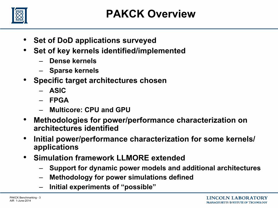
• Set of DoD applications surveyed • Set of key kernels identified/implemented
– Dense kernels – Sparse kernels
• Specific target architectures chosen – ASIC – FPGA – Multicore: CPU and GPU
• Methodologies for power/performance characterization on architectures identified
• Initial power/performance characterization for some kernels/applications
• Simulation framework LLMORE extended – Support for dynamic power models and additional architectures – Methodology for power simulations defined – Initial experiments of “possible”
PAKCK Benchmarking - 4 AIR 1-June-2014
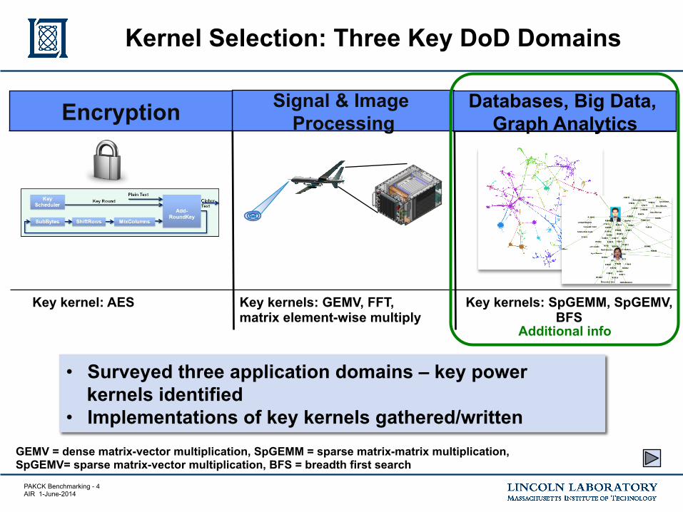
Kernel Selection: Three Key DoD Domains
Signal & Image Processing Encryption
Databases, Big Data, Graph Analytics
Key kernel: AES Key kernels: GEMV, FFT, matrix element-wise multiply
Key kernels: SpGEMM, SpGEMV, BFS
GEMV = dense matrix-vector multiplication, SpGEMM = sparse matrix-matrix multiplication, SpGEMV= sparse matrix-vector multiplication, BFS = breadth first search
• Surveyed three application domains – key power kernels identified
• Implementations of key kernels gathered/written
Additional info

PAKCK Benchmarking - 5 AIR 1-June-2014
Cyber
• Graphs represent communication patterns of computers on a network
• 1,000,000s – 1,000,000,000s network events
• GOAL: Detect cyber attacks or malicious software
Social
• Graphs represent relationships between individuals or documents
• 10,000s – 10,000,000s individual and interactions
• GOAL: Identify hidden social networks
• Graphs represent entities and relationships detected through multi-INT sources
• 1,000s – 1,000,000s tracks and locations
• GOAL: Identify anomalous patterns of life
ISR
Databases, Big Data, Graph Analysis
Cross-Mission Challenge: Detection of subtle patterns in massive multi-source noisy datasets
Source: Ben Miller, MITLL

PAKCK Benchmarking - 6 AIR 1-June-2014
Key Kernels in Graph Analytics
Breadth first search (BFS) Sparse matrix-dense vector multiplication (SpMV)
Sparse matrix-matrix multiplication (SpGEMM)
• Fundamental graph search algorithm
• Graph 500 benchmark • Simple algorithm that
stresses traditional architectures
• Workhorse of sparse iterative methods (eigensolvers, CG, GMRES, etc.)
• Signal processing for graphs
• Formation of correlation matrices
• DNA sequence matching
• Graph clustering
Computational challenges – Sparsity of data – Irregular data – Lack of data locality (spatial and temporal)

PAKCK Benchmarking - 7 AIR 1-June-2014
Performance Challenges in Graph Computations
10−5 10−4 10−3 10−2 10−1 10010−6
10−5
10−4
10−3
10−2
10−1
100
Fraction of Memory Used
Frac
tion
of P
eak
Perfo
rman
ce
densesparseassoccatkeycatval
Dense Linear Algebra ~100% Efficient. What COTS is designed to do.
Sparse Linear Algebra ~0.1% Efficient. What network analysis requires.
Sparse String Correlation ~0.001% Efficient. What semantic analysis requires.
Fraction of Memory Used
Frac
tion
of P
eak
Per
form
ance
1000x
100x
Source: Jeremy Kepner, MITLL
Performance for sparse linear algebra/graph operations significantly worse than dense linear algebra operations on COTS processors

PAKCK Benchmarking - 8 AIR 1-June-2014
Computational Architecture Choices
• Four specific architectures chosen • Methodologies for power performance characterization of four
architectures developed
ASIC FPGA Multicore 1 Multicore 2
65 nm CMOS IBM 10 LPe
Low Power Xilinx (Spartan 6,
Samsung 45 nm)
GPGPU: NVIDIA Fermi Intel Sandy Bridge
Simulator Simulator • PAPI/NVML • LLMORE
• PAPI/RAPL • LLMORE

PAKCK Benchmarking - 9 AIR 1-June-2014
Computational Architectures Comparison
Programmability of kernels
Cost of repurposing
Expected power consumption Parallelism
ASIC Complex design; long fab time
Time consuming and expensive to
refab O(1 mW)
Can be designed to be highly
parallel
FPGA Requires RTL programming
Write new RTL code O(100 mW) Limited by
number of gates
Nvidia Fermi
Requires CUDA programming
Write new CUDA code ~200 W
Highly parallel due to 100s of CUDA cores
Intel Sandy Bridge
Many programming
languages supported
Write new code ~135 W Limited by number of cores
Each architecture has different advantages and disadvantages
Low Medium High Very High

PAKCK Benchmarking - 10 AIR 1-June-2014
• Introduction
• Key Computational Kernels and Computational Architectures
• Results
• Exploration of Possible using LLMORE Simulator
• Other Key Benchmark Suites
• Summary and Future Work
Outline

PAKCK Benchmarking - 11 AIR 1-June-2014
• Performance Application Programming Interface (PAPI) provides access to hardware counters to monitor performance – Timing data – Cache hits/misses – Energy counters
• Running Average Power Limit (RAPL) for SandyBridge CPU
• NVIDIA Management Library (NVML) for NVIDIA GPGPU
• PAPI works across platforms • Accurate power estimates from
energy components
Characterizing CPU Power/Performance with PAPI
! CPU and graphics performance,! battery life and energy bills, and! ergonomics (acoustic noise, heat, and
so on).
To meet user preferences, the power-management algorithms optimize aroundthe following physical constraints:
! silicon capabilities, including voltage,frequency and power characteristics;
! system thermomechanical capabilities;! power-delivery capabilities;! software and operating system explicit
control; and! workload and usage characteristics.
The system designer can control thepower-management functionality’s behaviorand preferences via basic input/output sys-tem (BIOS) settings, runtime software, oran on-board embedded controller. At run-time, the system reads and controls parame-ters such as power, maximum currentconsumption, and die temperature.
Intel Turbo Boost technology 2.0The power and frequency of the CPU
and processor graphics are defined by a sce-nario of concurrent CPU and processorgraphics running a heavy workload at the
same time at worst-case conditions.1 Inmost cases, the CPU is running a less-demanding application and the Intel TurboBoost technology uses this power headroomto extract higher performance when possi-ble.2,3 Sandy Bridge’s power performancecontrol is performed primarily throughdynamic voltage and frequency scaling(DVFS). When the operating system identi-fies a need for high performance, it issues ahigh P-state request. Whenever power andthermal headroom exist, the PCU increasesthe voltage and frequency to the highestpoint that is lower than or equal to the oper-ating system request, that still meets all phys-ical constraints. Sandy Bridge implementsarchitectural power meters. It collects a setof architectural events from each Intel archi-tecture core, the processor graphics, and I/O,and combines them with energy weights topredict the package’s active power consump-tion. Leakage information is coded into thedie and is scaled with operating conditionssuch as voltage and temperature to providethe package’s total power consumption.The system uses architectural power predic-tor output, which is also exposed externallyto software, to decide the amount of turboupside available for the current workload(turbo upside is available higher frequencythat the CPU can go up to and use for higherperformance).4,5 The architectural powerpredictor provides a consistent turbo behaviorwhile minimizing the die-to-die variationsand dependency on ambient temperature.Figure 3 describes the actual versus predictedpower of the CPU, processor graphics, andtotal package.
In addition to the Intel Turbo Boost tech-nology already implemented in previous gen-erations of Intel processors, Sandy Bridgeoffers two new functionalities: total packagepower control and responsiveness via dy-namic turbo. Sandy Bridge is an SoC mono-lithic die. The power is specified in terms ofthe entire package’s total power consump-tion. The real workload uses the die’s differ-ent computational and communicationresources. The PCU continuously monitorsthe individual functional blocks’ power con-sumption and performs dynamic budget al-location to the various components. Onesuch example is power sharing between the
[3B2-9] mmi2012020020.3d 12/3/012 14:20 Page 22
454035302520151050
0 50 100 150 200 250Time (s)
CPU–predictedPG–predictedPackage–predicted
CPU–actualPG–actualPackage–actual
Pow
er (W
)
Figure 3. Power meter: predicted and actual power of the CPU, processor
graphics, and total package. The figure shows a power snapshot of
combined CPU and graphics workload. The chart presents the actual
measured power and the architectural power meter reporting for the IA
core, processor graphics, and total package. The actual and reported
power correlate accurately.
....................................................................
22 IEEE MICRO
...............................................................................................................................................................................................HOT CHIPS
Rotem et. al., IEEE Micro, 2012
RAPL Estimates v Measured Power Usage
PAKCK Benchmarking - 12 AIR 1-June-2014
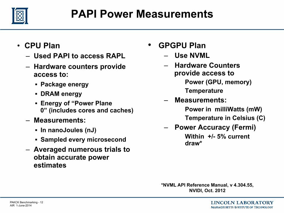
• CPU Plan – Used PAPI to access RAPL – Hardware counters provide
access to: § Package energy § DRAM energy § Energy of “Power Plane
0” (includes cores and caches) – Measurements:
§ In nanoJoules (nJ) § Sampled every microsecond
– Averaged numerous trials to obtain accurate power estimates
PAPI Power Measurements
• GPGPU Plan – Use NVML – Hardware Counters
provide access to Power (GPU, memory) Temperature
– Measurements: Power in milliWatts (mW) Temperature in Celsius (C)
– Power Accuracy (Fermi) Within +/- 5% current
draw*
*NVML API Reference Manual, v 4.304.55, NVIDI, Oct. 2012

PAKCK Benchmarking - 13 AIR 1-June-2014
Preliminary Power Characterization Results
• 75 GFLOPS/W can be achieved with ASIC for certain kernels
• FPGAs are close to goal
• Sparse kernels perform orders of magnitude lower than dense kernels
• 75 GFLOPS/W is very challenging target for software programmable architectures
PAKCK Benchmarking - 14 AIR 1-June-2014
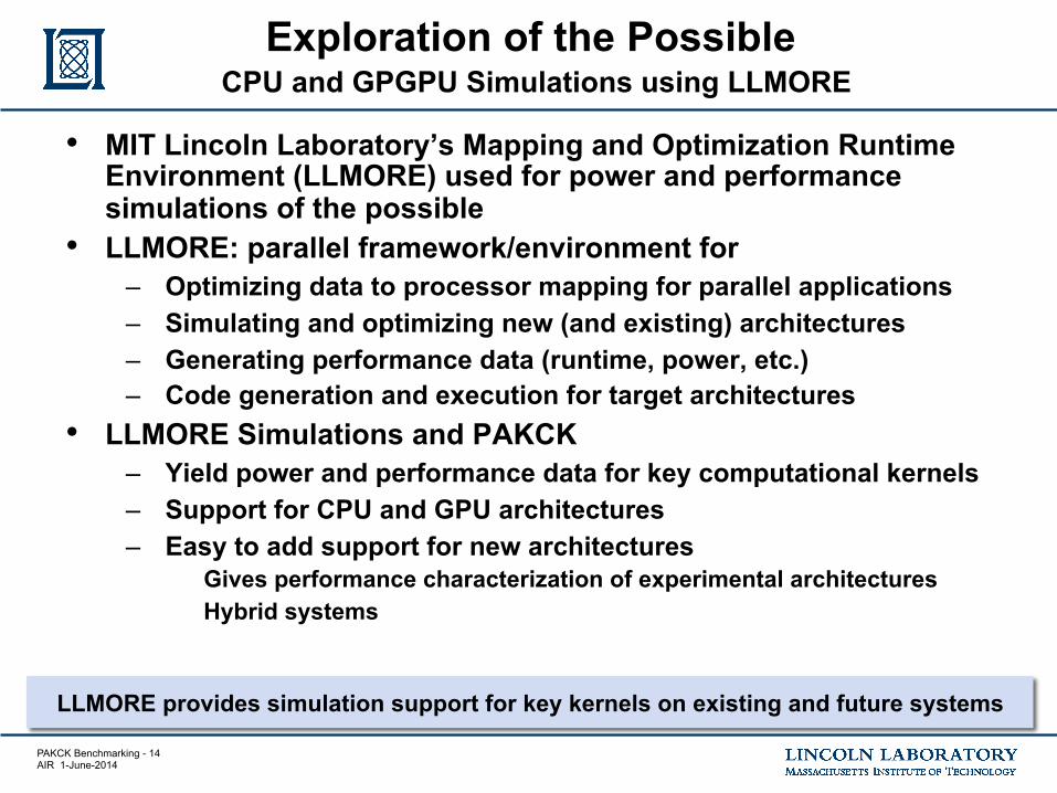
• MIT Lincoln Laboratory’s Mapping and Optimization Runtime Environment (LLMORE) used for power and performance simulations of the possible
• LLMORE: parallel framework/environment for – Optimizing data to processor mapping for parallel applications – Simulating and optimizing new (and existing) architectures – Generating performance data (runtime, power, etc.) – Code generation and execution for target architectures
• LLMORE Simulations and PAKCK – Yield power and performance data for key computational kernels – Support for CPU and GPU architectures – Easy to add support for new architectures
Gives performance characterization of experimental architectures Hybrid systems
Exploration of the Possible CPU and GPGPU Simulations using LLMORE
LLMORE provides simulation support for key kernels on existing and future systems

PAKCK Benchmarking - 15 AIR 1-June-2014
LLMORE Simulator Framework
LLMORE Simulator Framework
LLMORE interfaces to multiple simulators to support the analysis needs of different architectures.
LLMORE Simulator • High level simulation for
understanding big picture
• Fast • Low fidelity • Input: LLMORE MI code
Sniper Simulator • Low level simulator for
high fidelity simulation • Focus: simulation of big
systems, networks • Support for x86
instructions • Input: C++ code
Custom MITLL Simulator • Low level simulator for
high fidelity simulation • Focus: simulations of
processor with non x86 instructions
• Support for custom instructions, custom synchronization
• Input: program trace
MI=machine independent
External to LLMORE
LLMORE

PAKCK Benchmarking - 16 AIR 1-June-2014
LLMORE Overview
LLMORE Architectures
Applications
Architecture Model
User Code
Output: One or more
Production quality software that is extendable to new applications, architectures
3040
5060
7080
90 23
45
67
8
0.1
0.15
0.2
0.25
0.3
0.35
0.4
0.45
Memory: Static Power(W)
GFLOPs/W Nehalem Model − Dense
Processor: Static Power(W)
Performance Data
Optimized Architectures
Parameters Photonic BW = 320 Gb/s P = 16
Optimized Maps
A x y
Generated Code/Results
for i=1:N compute1() compute2() compute3() end

PAKCK Benchmarking - 17 AIR 1-June-2014
Sample LLMORE Simulation – 2D FFT
Architecture LLMORE
Architecture Model
User Code
Output
Performance Data
3040
5060
7080
90 23
45
67
8
0.1
0.15
0.2
0.25
0.3
0.35
0.4
0.45
Memory: Static Power(W)
GFLOPs/W Nehalem Model − Dense
Processor: Static Power(W)
LLMORE simulates running 2D FFT on Sandy Bridge CPU and produces performance data
Application
PAKCK Benchmarking - 18 AIR 1-June-2014
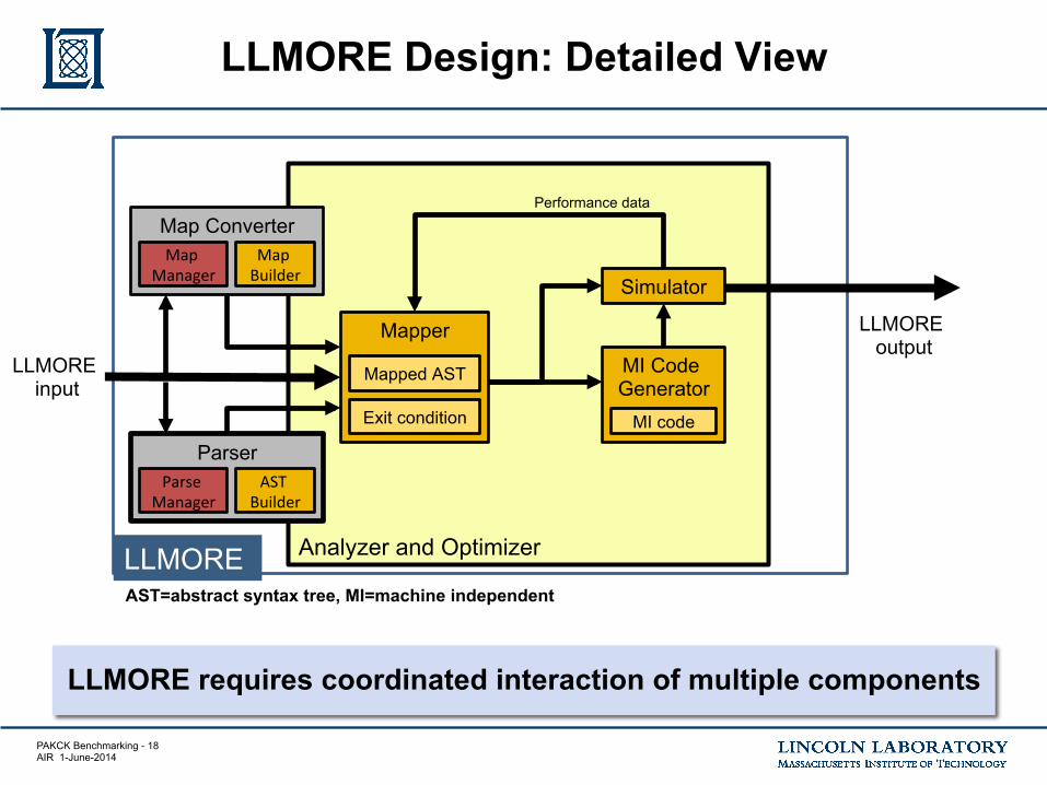
LLMORE Design: Detailed View
LLMORE
LLMORE output
Analyzer and Optimizer
Map Converter Map
Manager Map Builder
Parser Parse
Manager AST
Builder
LLMORE input
Mapper
Exit condition
Mapped AST MI Code Generator
MI code
Simulator
Performance data
LLMORE requires coordinated interaction of multiple components
AST=abstract syntax tree, MI=machine independent

PAKCK Benchmarking - 19 AIR 1-June-2014
LLMORE: Exploration of the Possible
Simulation indicates 50x-100x energy improvement needed in Intel Sandy Bridge to obtain 75 GFLOPS/W
LLMORE used to explore energy trade space for compute and
memory operations (scaling the energy per op)
GFL
OPS
/W

PAKCK Benchmarking - 20 AIR 1-June-2014
• Introduction
• Key Computational Kernels and Computational Architectures
• Results
• Exploration of Possible using LLMORE Simulator
• Other Key Benchmark Suites
• Summary and Future Work
Outline
PAKCK Benchmarking - 21 AIR 1-June-2014
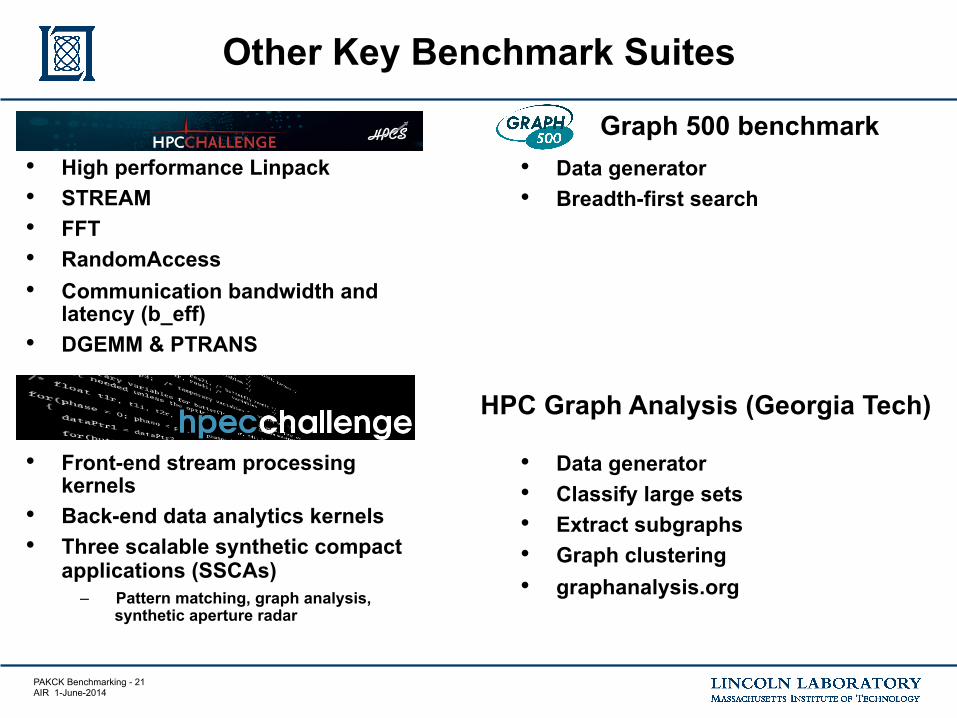
Other Key Benchmark Suites
• High performance Linpack • STREAM • FFT • RandomAccess • Communication bandwidth and
latency (b_eff) • DGEMM & PTRANS
• Front-end stream processing kernels
• Back-end data analytics kernels • Three scalable synthetic compact
applications (SSCAs) – Pattern matching, graph analysis,
synthetic aperture radar
• Data generator • Breadth-first search
• Data generator • Classify large sets • Extract subgraphs • Graph clustering • graphanalysis.org
HPC Graph Analysis (Georgia Tech)
Graph 500 benchmark

PAKCK Benchmarking - 22 AIR 1-June-2014
Parallel Computing Architecture Issues
CPU
RAM
Disk
CPU
RAM
Disk
CPU
RAM
Disk
CPU
RAM
Disk
Standard Parallel Computer Architecture
CPU
RAM
Disk
CPU
RAM
Disk
CPU
RAM
Disk
CPU
RAM
Disk
Network Switch
Corresponding Memory Hierarchy
Performance Implications
Incr
easi
ng B
andw
idth!
Incr
easi
ng L
aten
cy!
Incr
easi
ng C
apac
ity!
Incr
easi
ng P
rogr
amm
abili
ty!
• Standard architecture produces a “steep” multi-layered memory hierarchy • Programmer must manage this hierarchy to get good performance
Registers
Cache
Local Memory
Remote Memory
Disk
Instr. Operands
Blocks
Pages
Messages
PAKCK Benchmarking - 23 AIR 1-June-2014
Registers
Cache
Local Memory
Remote Memory
Disk
Instr. Operands
Blocks
Pages
Messages
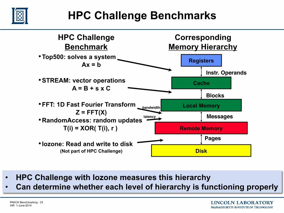
• HPC Challenge with Iozone measures this hierarchy • Can determine whether each level of hierarchy is functioning properly
HPC Challenge Benchmarks
HPC Challenge Benchmark
Corresponding Memory Hierarchy
• Top500: solves a system Ax = b
• STREAM: vector operations A = B + s x C
• FFT: 1D Fast Fourier Transform Z = FFT(X)
• RandomAccess: random updates T(i) = XOR( T(i), r )
• Iozone: Read and write to disk
(Not part of HPC Challenge)
bandwidth!
latency!

PAKCK Benchmarking - 24 AIR 1-June-2014
HPEC Challenge: Kernel Benchmark Selection
“Front-end Processing” • Data independent,
stream-oriented • Signal processing,
image processing, high-speed network communication
“Back-end Processing” • Data dependent, thread
oriented • Information processing,
knowledge processing
Broad Processing Categories Specific Kernels
Signal/Image Processing • Finite Impulse Response Filter (FIR) • QR Factorization (QR) • Singular Value Decomposition (SVD) • Constant False Alarm Rate Detection
(CFAR)
Communication • Corner Turn (CT)
Information/Knowledge Processing
• Graph Optimization via Genetic Algorithm (GA)
• Pattern Match (PM) • Real-time Database Operations (DB)
http://www.omgwiki.org/hpec/files/hpec-challenge/

PAKCK Benchmarking - 25 AIR 1-June-2014
HPEC Challenge: Signal and Image Processing Kernels
QR FIR
SVD CFAR
Data Set 1:!M Filters !(~10 coefficients)!
Data Set 2:!M Filters !(>100 coefficients)!
• Bank of filters applied to input data • FIR filters implemented in time and
frequency domain
Input Matrix!
M C
hann
els!
Input!Matrix!
Bidiagonal!Matrix!
Diagonal Matrix Σ!
• Produces decomposition of an input matrix, X=UΣVH
• Classic Golub-Kahan SVD implementation
A
• Computes the factorization of an input matrix, A=QR
• Implementation uses Fast Givens algorithm
*!Q R (MxN) (MxN) (MxM)
Beams
Dopplers
Range
C(i,j,k)
T(i,j,k)
C
• Creates a target list given a data cube • Calculates normalized power for each
cell, thresholds for target detection
Normalize, Threshold
Target List
(i,j,k)
http://www.omgwiki.org/hpec/files/hpec-challenge/

PAKCK Benchmarking - 26 AIR 1-June-2014
HPEC Challenge: Information and Knowledge Processing Kernels
Range!
Mag!
…!
Pattern under test!
Pattern Match Genetic Algorithm
Database Operations
• Compute best match for a pattern out of set of candidate patterns
– Uses weighted mean-square error 0.1!0.2!0.3!0.4!Selection!
Evaluation!
Crossover! Mutation!
• Evaluate each chromosome • Select chromosomes for next generation • Crossover: randomly pair up chromosomes
and exchange portions • Mutation: randomly change each chromosome
Red-Black Tree Data Structure
Linked List Data Structures
• Three generic database operations: – search: find all items in
a given range – insert: add items to the
database – delete: remove item
from the database
Candidate Pattern 1
Candidate Pattern 2
Candidate Pattern N
Corner Turn
0 1 2 3 4 5 6 7 8 9 10 11
1 5 9 2 6 10 3 7 11
0 4 8
• Memory rearrangement of matrix contents
– Switch from row to column major layout
http://www.omgwiki.org/hpec/files/hpec-challenge/

PAKCK Benchmarking - 27 AIR 1-June-2014
SAR Images
Front-End Sensor Processing
Template Files
Back-End Knowledge Formation
Validation
Template Files
Groups of Template Files
Raw SAR
Files
SAR Image
Scalable Data and Template
Generator
Kernel #2 Image
Storage
Groups of Template
Files
Sub-Image Detection Files
Image Files
Sub-Image Detection Files
Detections Kernel #4 Detection
SAR Image Template
Insertion
Kernel #3 Image
Retrieval Templates
Raw SAR File
SAR Image Files
SAR Image Files
Kernel #1 Data Read and Image Formation
Templates
Template Files
HPEC Challenge SSCA#3: SAR System Architecture
Raw SAR Data Files
Computation File IO
HPEC community has traditionally
focused on Computation …
… but File IO performance is
increasingly important
http://www.omgwiki.org/hpec/files/hpec-challenge/

PAKCK Benchmarking - 28 AIR 1-June-2014
Summary and Future Work
Summary • Major finding: DARPA is targeting ASIC-levels of computational
efficiency applied to programmable computational architectures • PAKCK results show this is a challenging goal to achieve • PAKCK has quantified the gap between current programmable
computational architectures and DARPA goal for DoD-relevant application kernels
Future Work • Characterize performance bottlenecks on Sandy Bridge for
SpMV and SpGEMM • Extend LLMORE to simulating other device technologies