PAINTING AND MARKING OF ARMY AIRCRAFTTM 55-1500-345-23 TECHNICAL MANUAL PAINTING AND MARKING OF ARMY...
386
TM 55-1500-345-23 TECHNICAL MANUAL PAINTING AND MARKING OF ARMY AIRCRAFT This publication supersedes TB 746-93-2 10 August 1978, including all changes HEADQUARTERS DEPARTMENT OF THE ARMY 12 JUNE 1986
Transcript of PAINTING AND MARKING OF ARMY AIRCRAFTTM 55-1500-345-23 TECHNICAL MANUAL PAINTING AND MARKING OF ARMY...
TM 55-1500-345-23
TECHNICAL MANUAL
PAINTING AND MARKINGOF ARMY AIRCRAFT
This publication supersedes TB 746-93-2 10 August 1978, including all changes
HEADQUARTERS DEPARTMENT OF THE ARMY
12 JUNE 1986


TM 55-1500-345-23
An operating procedure, practice, etc., which, if not correctly followed, could result in personnelinjury or loss of life.
An operating procedure, practice, etc., which, if not strictly observed, could result in damage to ordestruction of equipment.
NOTE
An operating procedure, condition etc., which it is essential to highlight.
PRECAUTIONARY DATAPersonnel performing instructions involving operations, procedures, and practices which are included or impliedin this technical manual shall observe the following instructions. Disregard of these warnings and precautionaryinformation can cause serious injury, death or an aborted mission.
USING SOLVENT/PAINTSStandard precautions such as .re prevention and adequate ventilation shall be exercised when using solvents orapplying primer and coating.
ELECTRICAL WIRINGDisconnect all electrical wiring before removing any part of aircraft.
ACETONE, ASTM-D329Acetone is extremely flammable an toxic to eyes, skin, and respiratory tract. Wear protective gloves and gog-gles/face shield. Avoid repeated or prolonged contact. Use only in well ventilated areas (or use approved respiratoras determined by local safety/industrial hygiene personnel). Keep away from open flames, sparks, hot surfaces orother sources of ignition.
ALIPHATIC NAPHTHA, TT-N-95Aliphatic Naphtha is extremely flammable an toxic to eyes, skin, and respiratory tract. Wear protective gloves andgoggles/face shield. Avoid repeated or prolonged contact. Use only in well ventilated areas (or use approved respi-rator as determined by local safety/industrial hygiene personnel). Keep away from open flames, sparks, hot surfacesor other sources of ignition.
Change 12 a/(b Blank)


TM 55-1500-345-23C 12
CHANGE
NO. 12
HEADQUATERSDEPARTMENT OF THE ARMY
WASHINGTON, D.C.,10 January 2011
PAINTING AND MARKING OF ARMY AIRCRAFT
DISTRIBUTION STATEMENT A: Approved for public release; distribution is unlimited.
TM 55-1500-345-23, dated 12 June 1986, is changed as follows:
1. Remove and insert pages as indicated below. New or changed text material is indicated by a vertical barin the margin. An illustration change is indicated by a miniature pointing hand.
Remove Pages Insert Pages
a/(b Blank) a/(b blank)A through C/(D blank) A and Bi and iv i and iv1-1 through 1-3/(1-4 blank) 1-1 through 1-3/(1-4 blank)2-3 and 2-4 2-3 and 2-43-3 through 3-18 3-3 through 3-183-29/(3-30 blank) 3-29/(3-30 blank)4-1 through 4-6 4-1 through 4-65-1 through 5-4 5-1 through 5-46-1 through 6-14 6-1 through 6-146-14.1 and 6-14.2 6-14.1 and 6-14.26-15 through 6-22 6-15 through 6-227-1 through 7-4 7-1 through 7-47-7 and 7-8 7-7 and 7-87-11 and 7-12 7-11 and 7-128-1 through 8-8 8-1 through 8-88-17 through 8-20 8-17 through 8-209-1 through 9-12 9-1/(9-2 blank)9-13 and 9-14 9-13 and 9-149-30.1 and 9-30.2 9-30.1 and 9-30.29-31 through 9-34 9-31 through 9-349-43 and 9-44 9-43 and 9-449-47 through 9-50 9-47 through 9-509-55 and 9-58 9-55 and 9-589-67 and 9-68 9-67 and 9-689-71 through 9-86 9-71 through 9-85/(9-86 blank)9-87 through 9-100 - - - - -9-101 and 9-102 9-101/(9-102 blank)9-103 to 9-108 - - - - -9-109 and 9-110 9-109 and 9-1109-115 through 9-124 9-115 through 9-1249-127 and 9-128 9-127 and 9-1289-129 through 9-176 - - - - -9-176.1/(9-176.2 blank) - - - - -9-177 through 9-180 9-177 through 9-1809-185 through 9-192 9-185 through 9-1929-195 through 9-200 9-195 through 9-2009-200.1 and 9-200.2 9-200.1 and 9-200.210-1 and 10-2 10-1 and 10-210-23 and 10-24 10-23 and 10-2410-25 through 10-54 10-31/(10-32 blank)10-55 through 10-64 10-55/(10-56 blank)

TM 55-1500-345-23C 12
Remove Pages Insert Pages
10-65 and 10-66 10-65/(10-66 blank)10-67 through 10-76 10-67/(10-68 blank)10-77 through 10-88 10-77/(10-78 blank)10-89 through 10-92 10-89 through 10-9210-95 and 10-96 10-95 and 10-96
2. Retain this sheet in front of manual for reference purposes.
By Order of the Secretary of the Army:
GEORGE W. CASEY, JR.
General, United States Army Chief of Staff
��32708
JOYCE E. MORROW Administrative Assistant to the
Secretary of the Army
Official:
Distribution: To be distributed in accordance with the initial distribution number (IDN) �11338 requirements for TM 55-1500-345-23.

TM 55-1500-345-23 C 11 CHANGE HEADQUARTERS
DEPARTMENT OF THE ARMY NO. 11 WASHINGTON, D.C., 9 February 2006
PAINTING AND MARKING OF
ARMY AIRCRAFT
DISTRIBUTION STATEMENT A: Approved for public release; distribution is unlimited. TM 55-1500-345-23, dated 12 June 1986, is changed as follows: 1. Remove and insert pages as indicated below. New or changed text material is indicated by a vertical
bar in the margin. An illustration change is indicated by a miniature pointin g hand. Remove Pages Insert Pages a/(b blank) a/(b blank) A through C/(D blank) A through C/(D blank) i and ii i and ii 2-7 and 2-8 2-7/(2- 8 blank) 3-15 through 3-18 3-15 through 3-18 8-1 through 8-8.1/(8-8.2 blank) 8-1 through 8-8 9-53 and 9-54 9-53 and 9-54 9-67 through 9-84 9-67 through 9-84 10-63/(10-64 blank) 10-63/(10-64 blank) 2. Retain this sheet in front of manual for reference purposes.
TM 1-1500-345-23 C11
DISTRIBUTION: To be distributed in accordance with Initial Distribution Number (IDN) 311338 requirements for TM 55-1500-345-23.
By Order of the Secretary of the Army:
PETER J. SCHOOMAKER General, United States Army
Chief of Staff Official:
SANDRA R. RILEY Administrative Assistant to the
Secretary of the Army 0602304

CHANGE
NO. 10
C10TM 55-1500-345-23
HEADQUARTERSDEPARTMENT OF THE ARMY
WASHINGTON, D.C., 26 JANUARY 2004
PAINTING AND MARKINGOF ARMY AIRCRAFT
DISTRIBUTION STATEMENT A: Approved for public release; distribution is unlimited.
TM 55-1500-345-23, dated 12 June 1986 , is changed as follows:
1. Remove and insert pages as indicated below. New or changed text material is indicated by a vertical barin the margin. An illustration change is indicated by a miniature pointing hand.
Remove pages Insert pages
A through C/(D blank) A through C/(D blank)1-1 and 1-2 1-1 and 1-22-7 and 2-8 2-7 and 2-84-3 and 4-4 4-3 and 4-4(10-55 blank)/10-56 10-55/(10-56 blank)10-57 through 10-62 ------10-63 through 10-66 10-63/(10-64 blank)
2. Retain this sheet in front of manual for reference purposes.
By Order of the Secretary of the Army:
Official:
PETER J. SCHOOMAKER General, United States Army
Chief of Staff
JOEL B. HUDSON Administrative Assistant to the Secretary of the Army
0334403
To be distributed in accordance with Initial Distribution Number (IDN) 311338, requirements forDISTRIBUTION:
TM 55-1500-345-23.

55-1500-345-23C9
CHANGE HEADQUARTERSDEPARTMENT OF THE ARMY
NO. 9 WASHINGTON, DC 19 July 2002
PAINTING AND MARKINGOF ARMY AIRCRAFT
DISTRIBUTION STATEMENT A: Approved for public release; distribution is unlimited.
TM 55-1500-345-23, 12 June 1986, is changed as follows:
1. Remove and insert pages as indicated below. New or changed text material is indicated by a verticalbar in the margin. An illustration change is indicated by a miniature pointing hand.
Remove Pages
a/(b blank)
v through xi/(xii blank)1-1 and 1-23-15 and 3-166-5 through 6-127-1 through 7-4
8-1 and 8-28-29 through 8-30
9-175 and 9-1769-181 and 9-1829-200.1 and 9-200.210-1 through 10-54
Insert Pages
a/(b blank)
v through xi/(xii blank)1-1 and 1-23-15 and 3-166-5 through 6-12
7-6 through 7-108-1 and 8-28-29 through 8-30
9-175 and 9-1769-181 and 9-1829-200.1 and 9-200.210-1 through 10-25(10-55 blank)/10-56
2. Retain this sheet in front of manual for reference purposes.
10-65 through 10-88
TM
10 -65 through 10-6610-55 and 10-56
8-31 through 8-36 8-31 through 8-36
7-5 through 7-107-1 through 7-4
A through C/(D blank)

By Order of the Secretary of the Army:
Official:
ERIC K. SHINSEKI General, United States Army Chief of Staff
JOEL B. HUDSON Administrative Assistant to the Secretary of the Army
TM 55-1500-345-23C9
0212807
DISTRIBUTION:To be distributed in accordance with Initial Distribution Number (IDN) 311338, requirementsfor TM 55-1500-0345-23.

TM 55-1500-345-23C8
CHANGE HEADQUARTERSDEPARTMENT OF THE ARMY
NO. 8 WASHINGTON, DC 30 December 1998
PAINTING AND MARKINGOF ARMY AIRCRAFT
DISTRIBUTION STATEMENT A: Approved for public release; distribution is unlimited.
TM 55-1500-345-23, 12 June 1986, is changed as follows:
1. Remove and insert pages as indicated below. New or changed text material is indicated by a verticalbar in the margin. An illustration change is indicated by a miniature pointing hand.
Remove Pages
a/(b blank)i and ii
2-1 and 2-22-5 through 2-83-15 through 3-183-29/(3-30 blank)4-3 and 4-46-1 and 6-26-13 and 6-146-17 and 6-188-5 through 8-89-7 and 9-89-111 and 9-1129-123 and 9-1249-161 through 9-176
Insert Pages
a/(b blank)i and ii
2-1 and 2-22-5 through 2-83-15 through 3-183-29/(3-30 blank)4-3 and 4-46-1 and 6-26-13 and 6-146-17 and 6-188-5 through 8-89-7 and 9-89-111 and 9-1129-123 and 9-1249-161 through 9-1769-176.1/(9-176.2 blank)
2. Retain this sheet in front of manual for reference purposes.
TM 55-1500-345-23C8
By Order of the Secretary of the Army:
By Order Of the Secretary of the Army:
O f f i c i a l :
Administrative Assistant to theSecretary of the Army
05283
DENNIS J. REIMERGeneral, United States Army
Chief of Staff
DISTRIBUTION: To be distributed in accordance with Initial Distribution No. (IDN) 311338, requirementsfor TM 55-1500-345-23.

TM 55-1500-345-23C7
CHANGE HEADQUARTERS,DEPARTMENT OF THE ARMY
NO.7 WASHINGTON, D.C., 20 September 1996
PAINTING AND MARKINGOF ARMY AIRCRAFT
DISTRIBUTION STATEMENT A: Approved for public release; distribution is unlimited.
TM 55150034523, 12 June 1986, is changed as follows:
1. Remove and insert pages as indicated below. New or changed text material is indicated by a vertical bar in themargin. An illustration change is indicated by a miniature pointing hand.
Remove pages Insert pages
i and ii i and ii1-1 and 1-2 1-1 and 1-22-1 and 2-2 2-1 and 2-23-3 and 3-4 3-3 and 3-4--------- 3-29/(3-30 blank)8-1 and 8-2 8-1 and 8-29-21 and 9-22 9-21 and 9-229-29 and 9-30 9-29 and 9-30-------------- 9-30.1/(9-30.2 blank)9-31 and 9-32 9-31 and 9-329-32.1/(9-32.2 blank) ----------------9-115 and 9-116 9-115 and 9-1169-119 and 9-120 9-119 and 9-1209-163 and 9-164 9-163 and 9-1649-185 through 9-192 9-185 through 9-1929-197 through 9-200.2 9-197 through 9-200.2
2. Retain this sheet in front of manual for reference purposes.
TM 55-1500-345-23C7
By Order of the Secretary of the Army:
DENNIS J. REIMEROfficial: General, United States Army
Chief of Staff
JOELB.HUDSONAdministrative Assistant to the
Secretary of the Army02988
DISTRIBUTION:To be distributed in accordance with DA Form 1231E, block no. 1338, requirements for TM 551500-345-23.

TM 55-1500-345-23C 6
CHANGE
NO. 6
HEADQUARTERS,DEPARTMENTS OF THE ARMY
WASHINGTON, D.C., 28 February 1995
PAINTING AND MARKINGOF ARMY AIRCRAFT
DISTRIBUTION STATEMENT A: Approved for public release; distribution is unlimited
TM 55-1500-345-23, 12 June 1986, is changed as follows:
1. Remove and insert pages as indicated below. New or changed text material is indicated by a vertical barin the margin. An illustration change is indicated by a miniature pointing hand.
Remove pages
i and ii
3-3 and 3-4
3-17 and 3-18
6-3 and 6-4
6-13 and 6-14
8-7 and 8-8
9-3 and 9-4
9-9 and 9-10
9-13 through 9-30- - - - - - - - - - - -
9-31 and 9-32
9-191 and 9-192
9-189 and 9-200
Insert pages
i and ii
3-3 and 3-4
3-17 and 3-18
6-3 and 6-4
6-13 and 6-14
8-7 and 8-8
9-3 and 9-4
9-9 and 9-10
9-13 through 9-30
9-30.1/(9-30.2 blank)
9-31 and 9-32
9-191 and 9-192
9-199 and 9-200
2. Retain this sheet in front of manual for reference purposes.

TM 55-1500-345-23
C 6
By Order of the Secretary of the Army:
Official:
MILTON H. HAMILTONAdministrative Assistant to the
Secretary of the Army
GORDON R. SULLIVANGeneral, United States Army
Chief of Staff
DISTRIBUTION:To be distributed in accordance with DA Form 12-25-E, block no. 1338, requirements for
TM 55-1500-345-23.

TM 55-1500-345-23C 5
CHANGE
NO. 5
HEADQUARTERSDEPARTMENT OF THE ARMY
WASHINGTON, D.C., 4 April 1994
PAINTING AND MARKINGOF ARMY AIRCRAFT
DISTRIBUTION STATEMENT A: Approved for public release; distribution is unlimited.
TM 55-1500-345-23,12 June 1986, is changed as follows
1. Remove and insert pages as indicated below. New or changed text material is indicated by a vertical barin the margin. An illustration change is indicated by a miniature pointing hand.
Remove pages
i and iiix and x1-1 and 1-26-17 and 6-187-11 and 7-127-19 and 7-20- - - - - - - - - - - -9-1 through 9-129-15 and 9-169-27 and 9-289-31 and 9-329-67 and 9-689-71 through 9-809-103 through 9-1069-111 through 9-1249-137 through 9-1429-157 through 9-1649-167 through 9-1769-181 through 9-200- - - - - - - - - - - - - - - -10-23 and 10-2410-49 and 10-5010-61 and 10-6210-65 and 10-6610-87 and 10-8810-111 and 10-112
Insert pages
i and iiix and x1-1 and 1-26-17 and 6-187-11 and 7-127-19 and 7-207-29/(7-30 blank)9-1 through 9-129-15 and 9-169-27 and 9-289-31 and 9-329-67 and 9-689-71 through 9-809-103 through 9-1069-111 through 9-1249-137 through 9-1429-157 through 9-1649-167 through 9-1769-181 through 9-2009-200.1 and 9-200.210-23 and 10-2410-49 and 10-5010-61 and 10-6210-65 and 10-6610-87 and 10-8810-111 and 10-112

T M 5 5 - 1 5 0 0 - 3 4 5 - 2 3C 5
2. Retain this sheet in front of manual for reference purposes.
By Order of the Secretary of the Army:
Official:
GORDON R. SULLIVANGeneral, United States Army
Chief of Staff
MILTON H. HAMILTONAdministrative Assistant to the
Secretary of the Army06573
DISTRIBUTION:To be distributed in accordance with DA Form 12-25-E, block no. 1338, requirements for
TM 55-1500-345-23.

TM 55-1500-345-23C 4
CHANGE
NO. 4
HEADQUARTERSDEPARTMENT OF THE ARMY
WASHINGTON, D.C., 28 February 1991
PAINTING AND MARKINGOF ARMY AIRCRAFT
TM 55-1500-345-23, 12 June 1986, is changed as follows:
1. Remove and insert pages as indicated below. New or changed text mater ia li s i nd ica ted by a ve r t i ca l ba r in the marg in . A n i l l u s t r a t i o n c h a n g e i s i n d i c a t e dby a miniature point ing hand.
Remove pages Insert pages
i t h r o u g h i v2-1 through 2-83-1 through 3-45-3 and 5-46-1 and 6-26-7 through 6-106-13 and 6-146-14 .1 /6 -14 .26-15 and 6-167-9 and 7-108-1 and 8-29-111 and 9-1129-115 and 9-1169-121 through 9-1249-131 through 9-1349-159 and 9-1609-167 and 9-1689-171 and 9-1729-177 through 9-1802028’s and Envelopes
i t h r o u g h i v2-1 through 2-83-1 through 3-45-3 and 5-46-1 and 6-26-7 through 6-106-13 and 6-146-14.1 and 6-14.26-15 and 6-167-9 and 7-108-1 and 8-29-111 and 9-1129-115 and 9-1169-121 through 9-1249-131 through 9-1349-159 and 9-1609-167 and 9-1689-171 and 9-1729-177 through 9-1802028’s and Envelopes
2. Reta in th i s shee t in f ron t o f manua l fo r re fe rence purposes .
By Order of theSecretary of the Army:
CARL E. VUONOGeneral, UnitedStates Army
Official: Chief of Staff
THOMAS F. SIKORABrigadier General, United States Army
The Adjutant General
DISTRIBUTION:To be distributed in accordance with DA Form 12-31-E, block no. 1338, AVUM and
AVIM maintenance requirements for TM 55-1500-345-23.


Change
NO. 3
TM 55-1500-345-23C 3
HEADQUARTERSDEPARTMENT OF THE ARMY
WASHINGTON, D.C., 09 November 1989
PAINTING AND MARKINGOF ARMY AIRCRAFT
TM 55-1500-345-23, 12 June 1986 is changed as follows:
1. Remove and insert pages as indicated below. New or changed text mater ia li s i nd ica ted by a ve r t i ca l ba r in the marg in . A n i l l u s t r a t i o n c h a n g e i s i n d i c a t e dby a miniature point ing hand.
Remove pages Insert pages
7-7 and 7-8 7-7 and 7-87-15 through 7-20 7-15 through 7-207-27 and 7-28 7-27 /7 -288-7 and 8-8 8-7 and 8-89-171 and 9-172 9-171 and 9-172
2 . Reta in th i s shee t in f ron t o f manua l fo r re fe rence purposes .
By Order of theSecretary of the Army:
CARL E. VUONOGeneraI, United States Army
Official: CbiefofStaff
WILLIAM J. MEEHAN IIBrigadier General, United States Army
The Adjutant General
DISTRIBUTION:To be distributed in accordance with DA Form 12-31, AVUM and AVIM Maintenance
requ i rements fo r A l l F ixed and Rota ry Wing A i rc ra f t .


TM 55-1500-345-23C 2
Change
NO. 2
HEADQUARTERSDEPARTMENT OF THE ARMY
WASHINGTON, D.C., 14 August 1989
PAINTING AND MARKINGOF ARMY AIRCRAFT
TM 55-1500-345-23, 12 June 1986 is changed as follows:
1. Remove and insert pages as indicated below. New or changed text mater ia li s i nd ica ted by a ve r t i ca l ba r in the marg in . A n i l l u s t r a t i o n c h a n g e i s i n d i c a t e dby a miniature point ing hand.
Remove pages Insert pages
1-1 and 1-22-3 and 2-45-1 and 5-26-13 and 6-14
- - -
6-19 and 6-207-1 and 7-28-1 and 8-28-3 and 8-49-129 and 9-1309-161 through 9-1649-171 and 9-1729-193 and 9-194
1-1 and 1-22-3 and 2-45-1 and 5-26-13 and 6-146 - 1 4 . 1 / 6 - 1 4 . 26-19 and 6-207-1 and 7-28-1 and 8-28-3 and 8-49-129 and 9-1309-161 through 9-1649-171 and 9-1729-193 and 9-194
2. Reta in th i s shee t in f ron t o f manua l fo r re fe rence purposes .
By Order of the Secretary of the Army:
Official:
WILLIAMJ.MEEHAN I IBrigadier General, United States Army
The Adjutant General
CARL E. VUONOGeneraI, United States Army
Chief of Staff
DISTRIBUTION:To be distributed in accordance with DA Form 12-31, AVUM and AVIM Maintenance
requ i rements fo r A l l F ixed and Rota ry Wing A i rc ra f t .


TM 55-1500-345-23C 1
CHANGE
NO. 1
HEADQUARTERSDEPARTMENT OF THE ARMY
WASHINGTON, D.C., 1 July 1988
PAINTING AND MARKINGOF ARMY AIRCRAFT
TM 55-1500-345-23, 12 June 1986 is changed as follows:
1. Remove and insert pages as indicated below. New or changed text mater ia li s i nd ica ted by a ve r t i ca l ba r in the marg in . A n i l l u s t r a t i o n c h a n g e i s i n d i c a t e dby a m in ia tu re po in t ing hand .
Remove pages Insert pages
a / bi a n d i iv through xx i / x i i1-1 and 1-21 - 3 / 1 - 42-7 and 2-83-1 through 3-4
- - -
3-5 through 3-83-13 through 3-164-1 and 4-25-3 and 5-46-1 and 6-26-13 through 6-166-19 through 6-22
- - -
7-1 through 7-47-7 through 7-288-5 through 8-8
- - -
8-23 and 8-24- - -
8-25 and 8-269-1 through 9-89-11 through 9-149-25 and 9-269-33 and 9-349-67 and 9-689-85 and 9-86
a / bi a n d i iv through xx i / x i i1-1 and 1-21 - 3 / 1 - 42-7 and 2-83-1 through 3-43 - 4 . 1 / 3 - 4 . 23-5 through 3-83-13 through 3-164-1 and 4-25-3 and 5-46-1 and 6-26-13 through 6-166-19 through 6-226 - 2 2 . 1 / 6 - 2 2 . 27-1 through 7-47-7 through 7-288-5 through 8-88 - 8 . 1 / 8 - 8 . 28-23 and 8-248 - 2 4 . 1 / 8 - 2 4 . 28-25 and 8-269-1 through 9-89-11 through 9-149-25 and 9-269-33 and 9-349-67 and 9-689-85 and 9-86
TM 55-1500-345-23C 1
Remove pages Insert pages
9-101 and 9-1029-109 through 9-1129-115 through 9-1229-127 through 9-1489-153 through 9-1729-175 through 9-1809-185 and 9-1869-195 and 9-19610-23 and 10-2410-39 and 10-4010-83 and 10-8410-111 and 10-112
9-101 and 9-1029-109 through 9-1129-115 through 9-1229-127 through 9-1489-153 through 9-1729-175 through 9-1809-185 and 9-1869-195 and 9-19610-23 and 10-2410-39 and 10-4010-83 and 10-8410-111 and 10-112
2. Retain these sheets in f ront of manual for reference purposes.
By Order of the Secretary of the Army:
CARL E. VUONOGeneral, United States Army
Official: Chief of Staff
WILLIAM J. MEEHAN IIBrigadier General, United States Army
The Adjutant General
DISTRIBUTION:To be distributed in accordance with DA Form 12-31-R, AVUM and AVIM requirements
fo r A l l F ixed and Rota ry Wing A i rc ra f t .

TM 55-1500-345-23
Change 12 A
LIST OF EFFECTIVE PAGES/WORK PACKAGES NOTE: The portion of text affected by the changes is indicated by a vertical line in the outer margins of the page. Changes to illustrations are indicated by miniature pointing hands. Changes to wiring diagrams are indicated by shaded areas. Date of issue for the original manual is: Original .......................... 18 June 1986 Change 6 ................................ 28 February 1995 Change 1 ....................... 1 July 1988 Change 7 ................................ 20 September 1996 Change 2 ....................... 14 August 1989 Change 8 ................................ 30 December 1998 Change 3 ....................... 9 November 1989 Change 9 ................................ 19 July 2002 Change 4 ....................... 28 February 1991 Change 10 .............................. 26 January 2004 Change 5 ....................... 4 April 1994 Change 11 .............................. 9 February 2006 Change 12 .............................. 10 January 2011 TOTAL NUMBER OF PAGES FOR FRONT AND REAR MATTER IS 18 AND TOTAL NUMBER OF WORK PACKAGES IS 37 CONSISTING OF THE FOLLOWING: Page/WP No. *Change No. Cover .......................................................... 0 Blank .......................................................... 0 a ................................................................. 12 b blank ........................................................ 12 A and B ....................................................... 12 C Deleted ................................................... 12 D blank Deleted .......................................... 12 i thru iv ........................................................ 12 v through xi Deleted ................................... 12 xii blank Deleted ......................................... 12 1-1 through 1-3 ........................................... 12 1-4 blank..................................................... 12 2-1 .............................................................. 7 2-2 .............................................................. 8 2-3 and 2-4 ................................................. 12 2-5 and 2-6 ................................................. 8 2-7 .............................................................. 11 2-8 blank..................................................... 11 3-1 .............................................................. 0 3-2 .............................................................. 4 3-3 .............................................................. 0 3-4 .............................................................. 12 3-4.1 ........................................................... 1 3-4.2 blank ................................................. 1 3-5 and 3-6 ................................................. 12 3-7 .............................................................. 1 3-8 and 3-9 ................................................. 12 3-10 ............................................................ 0 3-11 through 3-17 ....................................... 12 3-18 through 3-27 ....................................... 0 3-28 blank................................................... 0 3-29 ............................................................ 12 3-30 blank................................................... 12 4-1 through 4-6 ........................................... 12
Page/WP No. *Change No. 5-1 .............................................................. 2 5-2 and 5-3 ................................................. 12 5-4 .............................................................. 0 6-1 through 6-13 ......................................... 12 6-14 ............................................................ 8 6-14.1 ......................................................... 12 6-14.2 ......................................................... 4 6-15 through 6-19 ....................................... 12 6-20 ............................................................ 0 6-21 and 6-22 ............................................. 12 6-22.1 ......................................................... 1 6-22.2 blank ................................................ 1 6-23 ............................................................ 0 6-24 blank ................................................... 0 7-1 .............................................................. 12 7-2 .............................................................. 9 7-3 and 7-4 ................................................. 12 7-5 blank ..................................................... 9 7-6 .............................................................. 9 7-7 and 7-8 ................................................. 12 7-9 .............................................................. 9 7-10 ............................................................ 0 7-11 ............................................................ 1 7-12 ............................................................ 12 7-13 ............................................................ 0 7-14 and 7-15 ............................................. 1 7-16 ............................................................ 3 7-17 ............................................................ 1 7-18 ............................................................ 3 7-19 ............................................................ 5 7-20 through 7-26 ....................................... 1 7-27 ............................................................ 3 7-28 blank Deleted ..................................... 3 7-29 ............................................................ 5 7-30 blank ................................................... 5
TM 55-1500-345-23
B Change 12
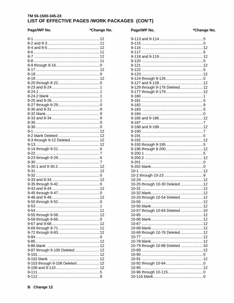
LIST OF EFFECTIVE PAGES /WORK PACKAGES (CON’T) Page/WP No. *Change No. 8-1 .............................................................. 12 8-2 and 8-3 ................................................. 11 8-4 and 8-5 ................................................. 12 8-6 .............................................................. 11 8-7 .............................................................. 12 8-8 .............................................................. 11 8-9 through 8-16 ......................................... 0 8-17 ............................................................ 12 8-18 ............................................................ 0 8-19 ............................................................ 12 8-20 through 8-22 ....................................... 0 8-23 and 8-24 ............................................. 1 8-24.1 ......................................................... 1 8-24.2 blank ............................................... 1 8-25 and 8-26 ............................................. 1 8-27 through 8-29 ....................................... 0 8-30 and 8-31 ............................................. 9 8-32 blank................................................... 9 8-33 and 8-34 ............................................. 9 8-35 ............................................................ 9 8-36 ............................................................ 0 9-1 .............................................................. 12 9-2 blank Deleted ....................................... 12 9-3 through 9-12 Deleted ........................... 12 9-13 ............................................................ 12 9-14 through 9-21 ....................................... 6 9-22 ............................................................ 7 9-23 through 9-29 ....................................... 6 9-30 ............................................................ 7 9-30.1 and 9-30.2 ....................................... 12 9-31 ............................................................ 12 9-32 ............................................................ 0 9-33 and 9-34 ............................................. 12 9-35 through 9-42 ....................................... 0 9-43 and 9-44 ............................................. 12 9-45 through 9-47 ....................................... 0 9-48 and 9-49 ............................................. 12 9-50 through 9-52 ....................................... 0 9-53 ............................................................ 1 9-54 ............................................................ 11 9-55 through 9-58 ....................................... 12 9-59 through 9-66 ....................................... 0 9-67 and 9-68 ............................................. 12 9-69 through 9-71 ....................................... 11 9-72 through 9-83 ....................................... 12 9-84 ............................................................ 0 9-85 ............................................................ 12 9-86 blank ................................................. 12 9-87 through 9-100 Deleted ....................... 12 9-101 .......................................................... 12 9-102 blank ............................................... 12 9-103 through 9-108 Deleted ..................... 12 9-109 and 9-110 ......................................... 12 9-111 .......................................................... 5 9-112 .......................................................... 8
Page/WP No. *Change No. 9-113 and 9-114 ......................................... 5 9-115 .......................................................... 0 9-116 .......................................................... 12 9-117 .......................................................... 5 9-118 and 9-119 ......................................... 12 9-120 .......................................................... 5 9-121 .......................................................... 12 9-122 .......................................................... 5 9-123 .......................................................... 12 9-124 through 9-126 ................................... 0 9-127 and 9-128 ......................................... 12 9-129 through 9-176 Deleted ..................... 12 9-177 through 9-179 ................................... 12 9-180 .......................................................... 1 9-181 .......................................................... 5 9-182 .......................................................... 9 9-183 ......................................................... 5 9-184 .......................................................... 0 9-185 and 9-186 ......................................... 12 9-187 .......................................................... 7 9-188 and 9-189 ......................................... 12 9-190 .......................................................... 7 9-191 .......................................................... 5 9-192 .......................................................... 12 9-193 through 9-195 ................................... 5 9-196 through 9-200 ................................... 12 9-200.1 ....................................................... 5 9-200.2 ....................................................... 12 9-201 .......................................................... 0 9-202 blank ................................................. 0 10-1 ............................................................ 12 10-2 through 10-23 ..................................... 9 10-24 .......................................................... 12 10-25 through 10-30 Deleted ..................... 12 10-31 .......................................................... 12 10-32 blank ................................................. 12 10-33 through 10-54 Deleted ..................... 12 10-55 .......................................................... 12 10-56 blank ................................................. 12 10-57 through 10-64 Deleted ..................... 10 10-65 .......................................................... 12 10-66 blank ................................................. 12 10-67 .......................................................... 12 10-68 blank ................................................. 12 10-69 through 10-76 Deleted ..................... 12 10-77 .......................................................... 12 10-78 blank ................................................. 12 10-79 through 10-88 Deleted ..................... 10 10-89 .......................................................... 12 10-90 .......................................................... 0 10-91 .......................................................... 12 10-92 through 10-94 ................................... 0 10-95 .......................................................... 12 10-96 through 10-115 ................................. 0 10-116 blank ............................................... 0
* TM 55-1500-345-23
TECHNICAL MANUAL HEADQUARTERSDEPARTMENT OF THE ARMY
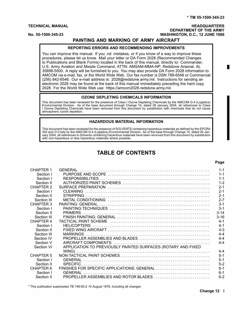
No. 55-1500-345-23 WASHINGTON, D.C., 12 JUNE 1986PAINTING AND MARKING OF ARMY AIRCRAFT
REPORTING ERRORS AND RECOMMENDING IMPROVEMENTSYou can improve this manual. If you .nd mistakes, or if you know of a way to improve theseprocedures, please let us know. Mail your letter or DA Form 2028 (Recommended Changesto Publications and Blank Forms) located in the back of this manual, directly to: Commander,U.S. Army Aviation and Missile Command, ATTN: AMSAM-MMA-NP, Redstone Arsenal, AL35898-5000. A reply will be furnished to you. You may also provide DA Form 2028 information toAMCOM via e-mail, fax, or the World Wide Web. Our fax number is DSN 788-6546 or Commercial(256) 842-6546. Our e-mail address is: [email protected]. Instructions for sending anelectronic 2028 may be found at the back of this manual immediately preceding the hard copy2028. For the World Wide Web use: https://amcom2028.redstone.army.mil.
OZONE DEPLETING CHEMICALS INFORMATIONThis document has been reviewed for the presence of Class I Ozone Depleting Chemicals by the AMCOM G-4 (Logistics)Environmental Division. As of the base document through Change 10, dated 26 January 2004, all references to ClassI Ozone Depleting Chemicals have been removed from this document by substitution with chemicals that do not causeatmospheric ozone depletion.
HAZARDOUS MATERIAL INFORMATION
This document has been reviewed for the presence of SOLVENTS containing hazardous materials as defined by the EPCRA302 and 313 lists by the AMCOM G-4 (Logistics) Environmental Division. As of the base through Change 10, dated 26 Jan-uary 2004, all references to Solvents containing hazardous materials have been removed from this document by substitutionwith non-hazardous or less hazardous materials where possible.
TABLE OF CONTENTSPage
CHAPTER 1 GENERAL . . . . . . . . . . . . . . . . . . . . . . . . . . . . . . . . . . . . . . . . . . . . . . . . . . . . . . . . . . . . . . . . . . . . . . 1-1Section I PURPOSE AND SCOPE . . . . . . . . . . . . . . . . . . . . . . . . . . . . . . . . . . . . . . . . . . . . . . . . . . . . . . . 1-1Section I RESPONSIBILITIES . . . . . . . . . . . . . . . . . . . . . . . . . . . . . . . . . . . . . . . . . . . . . . . . . . . . . . . . . . . 1-1Section II AUTHORIZED PAINT SCHEMES . . . . . . . . . . . . . . . . . . . . . . . . . . . . . . . . . . . . . . . . . . . . . . . 1-2
CHAPTER 2 SURFACE PREPARATION . . . . . . . . . . . . . . . . . . . . . . . . . . . . . . . . . . . . . . . . . . . . . . . . . . . . . . . 2-1Section I CLEANING . . . . . . . . . . . . . . . . . . . . . . . . . . . . . . . . . . . . . . . . . . . . . . . . . . . . . . . . . . . . . . . . . . . 2-1Section II STRIPPING . . . . . . . . . . . . . . . . . . . . . . . . . . . . . . . . . . . . . . . . . . . . . . . . . . . . . . . . . . . . . . . . . . . 2-1Section III METAL CONDITIONING . . . . . . . . . . . . . . . . . . . . . . . . . . . . . . . . . . . . . . . . . . . . . . . . . . . . . . . 2-7
CHAPTER 3 PAINTING: GENERAL . . . . . . . . . . . . . . . . . . . . . . . . . . . . . . . . . . . . . . . . . . . . . . . . . . . . . . . . . . . . 3-1Section I PAINTING TECHNIQUES . . . . . . . . . . . . . . . . . . . . . . . . . . . . . . . . . . . . . . . . . . . . . . . . . . . . . . 3-1Section II PRIMERS . . . . . . . . . . . . . . . . . . . . . . . . . . . . . . . . . . . . . . . . . . . . . . . . . . . . . . . . . . . . . . . . . . . . . 3-14Section III FINISH PAINTING: GENERAL . . . . . . . . . . . . . . . . . . . . . . . . . . . . . . . . . . . . . . . . . . . . . . . . . . 3-16
CHAPTER 4 TACTICAL PAINT SCHEME . . . . . . . . . . . . . . . . . . . . . . . . . . . . . . . . . . . . . . . . . . . . . . . . . . . . . . 4-1Section I HELICOPTERS . . . . . . . . . . . . . . . . . . . . . . . . . . . . . . . . . . . . . . . . . . . . . . . . . . . . . . . . . . . . . . . 4-1Section II FIXED WING AIRCRAFT . . . . . . . . . . . . . . . . . . . . . . . . . . . . . . . . . . . . . . . . . . . . . . . . . . . . . . . 4-3Section III MARKINGS . . . . . . . . . . . . . . . . . . . . . . . . . . . . . . . . . . . . . . . . . . . . . . . . . . . . . . . . . . . . . . . . . . . 4-4Section IV PROPELLER ASSEMBLIES AND BLADES . . . . . . . . . . . . . . . . . . . . . . . . . . . . . . . . . . . . . . 4-4Section V AIRCRAFT COMPONENTS . . . . . . . . . . . . . . . . . . . . . . . . . . . . . . . . . . . . . . . . . . . . . . . . . . . . 4-4Section VI APPLICATION TO PREVIOUSLY PAINTED SURFACES (ROTARY AND FIXED
WING) . . . . . . . . . . . . . . . . . . . . . . . . . . . . . . . . . . . . . . . . . . . . . . . . . . . . . . . . . . . . . . . . . . . . . . . . 4-4CHAPTER 5 NON-TACTICAL PAINT SCHEMES . . . . . . . . . . . . . . . . . . . . . . . . . . . . . . . . . . . . . . . . . . . . . . . . 5-1
Section I GENERAL . . . . . . . . . . . . . . . . . . . . . . . . . . . . . . . . . . . . . . . . . . . . . . . . . . . . . . . . . . . . . . . . . . . . 5-1Section II SPECIFIC . . . . . . . . . . . . . . . . . . . . . . . . . . . . . . . . . . . . . . . . . . . . . . . . . . . . . . . . . . . . . . . . . . . . . 5-2
CHAPTER 6 FINISHES FOR SPECIFIC APPLICATIONS: GENERAL . . . . . . . . . . . . . . . . . . . . . . . . . . . . . 6-1Section I GENERAL . . . . . . . . . . . . . . . . . . . . . . . . . . . . . . . . . . . . . . . . . . . . . . . . . . . . . . . . . . . . . . . . . . . . 6-1Section II PROPELLER ASSEMBLIES AND ROTOR BLADES . . . . . . . . . . . . . . . . . . . . . . . . . . . . . . 6-2
* This publication supersedes TB 746-93-2 10 August 1978, including all changesChange 12 i

TM 55-1500-345-23
TABLE OF CONTENTS (Cont)Page
Section I GENERAL . . . . . . . . . . . . . . . . . . . . . . . . . . . . . . . . . . . . . . . . . . . . . . . . . . . . . . . . . . . . . . . . . . . . 6-1Section II PROPELLER ASSEMBLIES AND ROTOR BLADES . . . . . . . . . . . . . . . . . . . . . . . . . . . . . . 6-2Section III AIRCRAFT EXTERIOR LANDING GEAR AND WHEELS . . . . . . . . . . . . . . . . . . . . . . . . . . 6-5Section IV WALKWAY COATINGS . . . . . . . . . . . . . . . . . . . . . . . . . . . . . . . . . . . . . . . . . . . . . . . . . . . . . . . . 6-5Section V INTERIOR PAINTING . . . . . . . . . . . . . . . . . . . . . . . . . . . . . . . . . . . . . . . . . . . . . . . . . . . . . . . . . . 6-14.1Section VI PROTECTIVE COATINGS . . . . . . . . . . . . . . . . . . . . . . . . . . . . . . . . . . . . . . . . . . . . . . . . . . . . . 6-20
CHAPTER 7 LETTERING AND MARKING . . . . . . . . . . . . . . . . . . . . . . . . . . . . . . . . . . . . . . . . . . . . . . . . . . . . . 7-1Section I MARKINGS . . . . . . . . . . . . . . . . . . . . . . . . . . . . . . . . . . . . . . . . . . . . . . . . . . . . . . . . . . . . . . . . . . . 7-1Section II INSIGNIA: GENERAL . . . . . . . . . . . . . . . . . . . . . . . . . . . . . . . . . . . . . . . . . . . . . . . . . . . . . . . . . . 7-1Section III MEDICAL INSIGNIA . . . . . . . . . . . . . . . . . . . . . . . . . . . . . . . . . . . . . . . . . . . . . . . . . . . . . . . . . . . 7-3Section IV COMMAND AND ORGANIZATIONAL INSIGNIA AND NAME . . . . . . . . . . . . . . . . . . . . . . 7-4Section V IDENTIFICATION LETTERING . . . . . . . . . . . . . . . . . . . . . . . . . . . . . . . . . . . . . . . . . . . . . . . . . 7-5Section VI WARNING STRIPES AND SIGNS . . . . . . . . . . . . . . . . . . . . . . . . . . . . . . . . . . . . . . . . . . . . . . . 7-7Section VII RADIO CALL NUMBERS AND PREFIXES . . . . . . . . . . . . . . . . . . . . . . . . . . . . . . . . . . . . . . . 7-9Section VIII SERIAL NUMBER AND FUEL SPECIFICATION . . . . . . . . . . . . . . . . . . . . . . . . . . . . . . . . . . 7-10Section IX MARKINGS FOR EMERGENCY ENTRY OR EXIT . . . . . . . . . . . . . . . . . . . . . . . . . . . . . . . 7-11Section X MISCELLANEOUS MARKINGS . . . . . . . . . . . . . . . . . . . . . . . . . . . . . . . . . . . . . . . . . . . . . . . . . 7-12Section XI MARKING OF INSTRUMENTS . . . . . . . . . . . . . . . . . . . . . . . . . . . . . . . . . . . . . . . . . . . . . . . . . 7-17
CHAPTER 8 MISCELLANEOUS TABLES AND ILLUSTRATIONS . . . . . . . . . . . . . . . . . . . . . . . . . . . . . . . . 8-1CHAPTER 9 HELICOPTER ILLUSTRATIONS . . . . . . . . . . . . . . . . . . . . . . . . . . . . . . . . . . . . . . . . . . . . . . . . . . 9-1
Section I DELETED . . . . . . . . . . . . . . . . . . . . . . . . . . . . . . . . . . . . . . . . . . . . . . . . . . . . . . . . . . . . . . . . . . . . . 9-1Section II AH-64 Illustrations . . . . . . . . . . . . . . . . . . . . . . . . . . . . . . . . . . . . . . . . . . . . . . . . . . . . . . . . . . . . . 9-13Section III CH-47 Illustrations . . . . . . . . . . . . . . . . . . . . . . . . . . . . . . . . . . . . . . . . . . . . . . . . . . . . . . . . . . . . . 9-33Section IV DELETED . . . . . . . . . . . . . . . . . . . . . . . . . . . . . . . . . . . . . . . . . . . . . . . . . . . . . . . . . . . . . . . . . . . . . 9-85Section V DELETED . . . . . . . . . . . . . . . . . . . . . . . . . . . . . . . . . . . . . . . . . . . . . . . . . . . . . . . . . . . . . . . . . . . . . 9-101Section VI OH-58 ILLUSTRATIONS . . . . . . . . . . . . . . . . . . . . . . . . . . . . . . . . . . . . . . . . . . . . . . . . . . . . . . . 9-109Section VII DELETED . . . . . . . . . . . . . . . . . . . . . . . . . . . . . . . . . . . . . . . . . . . . . . . . . . . . . . . . . . . . . . . . . . . . . 9-127Section VIII DELETED . . . . . . . . . . . . . . . . . . . . . . . . . . . . . . . . . . . . . . . . . . . . . . . . . . . . . . . . . . . . . . . . . . . . . 9-128Section IX UH-60 ILLUSTRATIONS . . . . . . . . . . . . . . . . . . . . . . . . . . . . . . . . . . . . . . . . . . . . . . . . . . . . . . . 9-178
CHAPTER 10 FIXED WING AIRCRAFT ILLUSTRATIONS . . . . . . . . . . . . . . . . . . . . . . . . . . . . . . . . . . . . . . . . 10-1Section I GENERAL . . . . . . . . . . . . . . . . . . . . . . . . . . . . . . . . . . . . . . . . . . . . . . . . . . . . . . . . . . . . . . . . . . . . 10-1Section II C12 and RC-12 Illustrations . . . . . . . . . . . . . . . . . . . . . . . . . . . . . . . . . . . . . . . . . . . . . . . . . . . . 10-2Section III DELETED . . . . . . . . . . . . . . . . . . . . . . . . . . . . . . . . . . . . . . . . . . . . . . . . . . . . . . . . . . . . . . . . . . . . . 10-31Section IV DELETED . . . . . . . . . . . . . . . . . . . . . . . . . . . . . . . . . . . . . . . . . . . . . . . . . . . . . . . . . . . . . . . . . . . . . 10-55Section V DELETED . . . . . . . . . . . . . . . . . . . . . . . . . . . . . . . . . . . . . . . . . . . . . . . . . . . . . . . . . . . . . . . . . . . . . 10-65Section VI DELETED . . . . . . . . . . . . . . . . . . . . . . . . . . . . . . . . . . . . . . . . . . . . . . . . . . . . . . . . . . . . . . . . . . . . . 10-67Section VII DELETED . . . . . . . . . . . . . . . . . . . . . . . . . . . . . . . . . . . . . . . . . . . . . . . . . . . . . . . . . . . . . . . . . . . . . 10-77Section VIII U-21 and RU-21 ILLUSTRATIONS . . . . . . . . . . . . . . . . . . . . . . . . . . . . . . . . . . . . . . . . . . . . . . 10-89
LIST OF ILLUSTRATIONS
Figure Title Page
1-1 or Identi.er Symbol . . . . . . . . . . . . . . . . . . . . . . . . . . . . . . . . . . . . . . . . . . . . . . . . . . . . . . . . . . . . . . . . . . . . . . . 1-33-1 Right and Methods of Spraying . . . . . . . . . . . . . . . . . . . . . . . . . . . . . . . . . . . . . . . . . . . . . . . . . . . . . . . . . . . . 3-93-2 Cross-Coating . . . . . . . . . . . . . . . . . . . . . . . . . . . . . . . . . . . . . . . . . . . . . . . . . . . . . . . . . . . . . . . . . . . . . . . . . . . 3-103-3 Fifty Percent Overlap . . . . . . . . . . . . . . . . . . . . . . . . . . . . . . . . . . . . . . . . . . . . . . . . . . . . . . . . . . . . . . . . . . . . . 3-103-4 Setting Spray Pattern. . . . . . . . . . . . . . . . . . . . . . . . . . . . . . . . . . . . . . . . . . . . . . . . . . . . . . . . . . . . . . . . . . . . . 3-123-5 Faulty Patterns and Suggested Corrections . . . . . . . . . . . . . . . . . . . . . . . . . . . . . . . . . . . . . . . . . . . . . . . . . 3-143-6 Excessive Spray Fog . . . . . . . . . . . . . . . . . . . . . . . . . . . . . . . . . . . . . . . . . . . . . . . . . . . . . . . . . . . . . . . . . . . . . 3-243-7 Paint Leaks From Spray Gun . . . . . . . . . . . . . . . . . . . . . . . . . . . . . . . . . . . . . . . . . . . . . . . . . . . . . . . . . . . . . . 3-243-8 Gun Sputters Constantly . . . . . . . . . . . . . . . . . . . . . . . . . . . . . . . . . . . . . . . . . . . . . . . . . . . . . . . . . . . . . . . . . . 3-24
ii Change 12
TM 55-1500-345-23
LIST OF ILLUSTRATIONS (Cont)
Figure Title Page
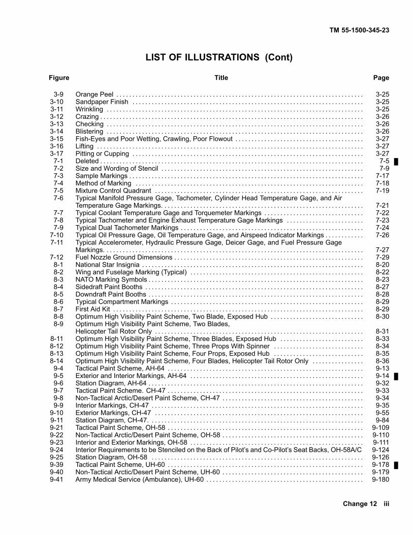
3-9 Orange Peel . . . . . . . . . . . . . . . . . . . . . . . . . . . . . . . . . . . . . . . . . . . . . . . . . . . . . . . . . . . . . . . . . . . . . . . . . . . . . 3-253-10 Sandpaper Finish . . . . . . . . . . . . . . . . . . . . . . . . . . . . . . . . . . . . . . . . . . . . . . . . . . . . . . . . . . . . . . . . . . . . . . . . 3-253-11 Wrinkling . . . . . . . . . . . . . . . . . . . . . . . . . . . . . . . . . . . . . . . . . . . . . . . . . . . . . . . . . . . . . . . . . . . . . . . . . . . . . . . . 3-253-12 Crazing . . . . . . . . . . . . . . . . . . . . . . . . . . . . . . . . . . . . . . . . . . . . . . . . . . . . . . . . . . . . . . . . . . . . . . . . . . . . . . . . . . 3-263-13 Checking . . . . . . . . . . . . . . . . . . . . . . . . . . . . . . . . . . . . . . . . . . . . . . . . . . . . . . . . . . . . . . . . . . . . . . . . . . . . . . . . 3-263-14 Blistering . . . . . . . . . . . . . . . . . . . . . . . . . . . . . . . . . . . . . . . . . . . . . . . . . . . . . . . . . . . . . . . . . . . . . . . . . . . . . . . . 3-263-15 Fish-Eyes and Poor Wetting, Crawling, Poor Flowout . . . . . . . . . . . . . . . . . . . . . . . . . . . . . . . . . . . . . . . . 3-273-16 Lifting . . . . . . . . . . . . . . . . . . . . . . . . . . . . . . . . . . . . . . . . . . . . . . . . . . . . . . . . . . . . . . . . . . . . . . . . . . . . . . . . . . . 3-273-17 Pitting or Cupping . . . . . . . . . . . . . . . . . . . . . . . . . . . . . . . . . . . . . . . . . . . . . . . . . . . . . . . . . . . . . . . . . . . . . . . . 3-277-1 Deleted . . . . . . . . . . . . . . . . . . . . . . . . . . . . . . . . . . . . . . . . . . . . . . . . . . . . . . . . . . . . . . . . . . . . . . . . . . . . . . . . . . 7-57-2 Size and Wording of Stencil . . . . . . . . . . . . . . . . . . . . . . . . . . . . . . . . . . . . . . . . . . . . . . . . . . . . . . . . . . . . . . . 7-97-3 Sample Markings . . . . . . . . . . . . . . . . . . . . . . . . . . . . . . . . . . . . . . . . . . . . . . . . . . . . . . . . . . . . . . . . . . . . . . . . . 7-177-4 Method of Marking . . . . . . . . . . . . . . . . . . . . . . . . . . . . . . . . . . . . . . . . . . . . . . . . . . . . . . . . . . . . . . . . . . . . . . . 7-187-5 Mixture Control Quadrant . . . . . . . . . . . . . . . . . . . . . . . . . . . . . . . . . . . . . . . . . . . . . . . . . . . . . . . . . . . . . . . . . 7-197-6 Typical Manifold Pressure Gage, Tachometer, Cylinder Head Temperature Gage, and Air
Temperature Gage Markings. . . . . . . . . . . . . . . . . . . . . . . . . . . . . . . . . . . . . . . . . . . . . . . . . . . . . . . . . . . . . . . 7-217-7 Typical Coolant Temperature Gage and Torquemeter Markings . . . . . . . . . . . . . . . . . . . . . . . . . . . . . . . 7-227-8 Typical Tachometer and Engine Exhaust Temperature Gage Markings . . . . . . . . . . . . . . . . . . . . . . . . 7-237-9 Typical Dual Tachometer Markings . . . . . . . . . . . . . . . . . . . . . . . . . . . . . . . . . . . . . . . . . . . . . . . . . . . . . . . . . 7-24
7-10 Typical Oil Pressure Gage, Oil Temperature Gage, and Airspeed Indicator Markings . . . . . . . . . . . . 7-267-11 Typical Accelerometer, Hydraulic Pressure Gage, Deicer Gage, and Fuel Pressure Gage
Markings. . . . . . . . . . . . . . . . . . . . . . . . . . . . . . . . . . . . . . . . . . . . . . . . . . . . . . . . . . . . . . . . . . . . . . . . . . . . . . . . . 7-277-12 Fuel Nozzle Ground Dimensions . . . . . . . . . . . . . . . . . . . . . . . . . . . . . . . . . . . . . . . . . . . . . . . . . . . . . . . . . . . 7-298-1 National Star Insignia . . . . . . . . . . . . . . . . . . . . . . . . . . . . . . . . . . . . . . . . . . . . . . . . . . . . . . . . . . . . . . . . . . . . . 8-208-2 Wing and Fuselage Marking (Typical) . . . . . . . . . . . . . . . . . . . . . . . . . . . . . . . . . . . . . . . . . . . . . . . . . . . . . . 8-228-3 NATO Marking Symbols . . . . . . . . . . . . . . . . . . . . . . . . . . . . . . . . . . . . . . . . . . . . . . . . . . . . . . . . . . . . . . . . . . . 8-238-4 Sidedraft Paint Booths . . . . . . . . . . . . . . . . . . . . . . . . . . . . . . . . . . . . . . . . . . . . . . . . . . . . . . . . . . . . . . . . . . . . 8-278-5 Downdraft Paint Booths . . . . . . . . . . . . . . . . . . . . . . . . . . . . . . . . . . . . . . . . . . . . . . . . . . . . . . . . . . . . . . . . . . . 8-288-6 Typical Compartment Markings . . . . . . . . . . . . . . . . . . . . . . . . . . . . . . . . . . . . . . . . . . . . . . . . . . . . . . . . . . . . 8-298-7 First Aid Kit . . . . . . . . . . . . . . . . . . . . . . . . . . . . . . . . . . . . . . . . . . . . . . . . . . . . . . . . . . . . . . . . . . . . . . . . . . . . . . 8-298-8 Optimum High Visibility Paint Scheme, Two Blade, Exposed Hub . . . . . . . . . . . . . . . . . . . . . . . . . . . . . 8-308-9 Optimum High Visibility Paint Scheme, Two Blades,
Helicopter Tail Rotor Only . . . . . . . . . . . . . . . . . . . . . . . . . . . . . . . . . . . . . . . . . . . . . . . . . . . . . . . . . . . . . . . . . 8-318-11 Optimum High Visibility Paint Scheme, Three Blades, Exposed Hub . . . . . . . . . . . . . . . . . . . . . . . . . . 8-338-12 Optimum High Visibility Paint Scheme, Three Props With Spinner . . . . . . . . . . . . . . . . . . . . . . . . . . . . 8-348-13 Optimum High Visibility Paint Scheme, Four Props, Exposed Hub . . . . . . . . . . . . . . . . . . . . . . . . . . . . 8-358-14 Optimum High Visibility Paint Scheme, Four Blades, Helicopter Tail Rotor Only . . . . . . . . . . . . . . . . 8-369-4 Tactical Paint Scheme, AH-64 . . . . . . . . . . . . . . . . . . . . . . . . . . . . . . . . . . . . . . . . . . . . . . . . . . . . . . . . . . . . . 9-139-5 Exterior and Interior Markings, AH-64 . . . . . . . . . . . . . . . . . . . . . . . . . . . . . . . . . . . . . . . . . . . . . . . . . . . . . . 9-149-6 Station Diagram, AH-64 . . . . . . . . . . . . . . . . . . . . . . . . . . . . . . . . . . . . . . . . . . . . . . . . . . . . . . . . . . . . . . . . . . . 9-329-7 Tactical Paint Scheme. CH-47 . . . . . . . . . . . . . . . . . . . . . . . . . . . . . . . . . . . . . . . . . . . . . . . . . . . . . . . . . . . . . 9-339-8 Non-Tactical Arctic/Desert Paint Scheme, CH-47 . . . . . . . . . . . . . . . . . . . . . . . . . . . . . . . . . . . . . . . . . . . . 9-349-9 Interior Markings, CH-47 . . . . . . . . . . . . . . . . . . . . . . . . . . . . . . . . . . . . . . . . . . . . . . . . . . . . . . . . . . . . . . . . . . 9-35
9-10 Exterior Markings, CH-47 . . . . . . . . . . . . . . . . . . . . . . . . . . . . . . . . . . . . . . . . . . . . . . . . . . . . . . . . . . . . . . . . . 9-559-11 Station Diagram, CH-47. . . . . . . . . . . . . . . . . . . . . . . . . . . . . . . . . . . . . . . . . . . . . . . . . . . . . . . . . . . . . . . . . . . 9-849-21 Tactical Paint Scheme, OH-58 . . . . . . . . . . . . . . . . . . . . . . . . . . . . . . . . . . . . . . . . . . . . . . . . . . . . . . . . . . . . . 9-1099-22 Non-Tactical Arctic/Desert Paint Scheme, OH-58 . . . . . . . . . . . . . . . . . . . . . . . . . . . . . . . . . . . . . . . . . . . . 9-1109-23 Interior and Exterior Markings, OH-58 . . . . . . . . . . . . . . . . . . . . . . . . . . . . . . . . . . . . . . . . . . . . . . . . . . . . . . 9-1119-24 Interior Requirements to be Stenciled on the Back of Pilot’s and Co-Pilot’s Seat Backs, OH-58A/C 9-1249-25 Station Diagram, OH-58 . . . . . . . . . . . . . . . . . . . . . . . . . . . . . . . . . . . . . . . . . . . . . . . . . . . . . . . . . . . . . . . . . . 9-1269-39 Tactical Paint Scheme, UH-60 . . . . . . . . . . . . . . . . . . . . . . . . . . . . . . . . . . . . . . . . . . . . . . . . . . . . . . . . . . . . . 9-1789-40 Non-Tactical Arctic/Desert Paint Scheme, UH-60 . . . . . . . . . . . . . . . . . . . . . . . . . . . . . . . . . . . . . . . . . . . . 9-1799-41 Army Medical Service (Ambulance), UH-60 . . . . . . . . . . . . . . . . . . . . . . . . . . . . . . . . . . . . . . . . . . . . . . . . . 9-180
Change 12 iii

TM 55-1500-345-23
LIST OF ILLUSTRATIONS (Cont)
Figure Title Page
9-42 Exterior and Interior Markings, UH-60 . . . . . . . . . . . . . . . . . . . . . . . . . . . . . . . . . . . . . . . . . . . . . . . . . . . . . . 9-1819-43 Station Locations, UH-60 . . . . . . . . . . . . . . . . . . . . . . . . . . . . . . . . . . . . . . . . . . . . . . . . . . . . . . . . . . . . . . . . . . 9-20110-1 Exterior Markings, C-12 . . . . . . . . . . . . . . . . . . . . . . . . . . . . . . . . . . . . . . . . . . . . . . . . . . . . . . . . . . . . . . . . . . . 10-210-2 Station Diagram, C-12 . . . . . . . . . . . . . . . . . . . . . . . . . . . . . . . . . . . . . . . . . . . . . . . . . . . . . . . . . . . . . . . . . . . . 10-2410-18 Tactical Paint Scheme, RU-21 . . . . . . . . . . . . . . . . . . . . . . . . . . . . . . . . . . . . . . . . . . . . . . . . . . . . . . . . . . . . . 10-8910-19 Non-Tactical Paint Scheme, U-21 . . . . . . . . . . . . . . . . . . . . . . . . . . . . . . . . . . . . . . . . . . . . . . . . . . . . . . . . . . 10-9110-20 Non-Tactical, High Visibility Paint Scheme, U-21 . . . . . . . . . . . . . . . . . . . . . . . . . . . . . . . . . . . . . . . . . . . . 10-9510-21 Interior Markings, U-21 and RU-21 . . . . . . . . . . . . . . . . . . . . . . . . . . . . . . . . . . . . . . . . . . . . . . . . . . . . . . . . . 10-9710-22 Exterior Markings, U-21 and RU-21 . . . . . . . . . . . . . . . . . . . . . . . . . . . . . . . . . . . . . . . . . . . . . . . . . . . . . . . . 10-10210-23 Station Diagram, U-21 and RU-21 . . . . . . . . . . . . . . . . . . . . . . . . . . . . . . . . . . . . . . . . . . . . . . . . . . . . . . . . . 10-25
LIST OF TABLES
Number Title Page
3-1 Manual Spray Coating Troubles, Possible Causes, and Remedies . . . . . . . . . . . . . . . . . . . . . . . . . . . . 3-186-1 Typical Aircraft Interior Areas To Be Painted . . . . . . . . . . . . . . . . . . . . . . . . . . . . . . . . . . . . . . . . . . . . . . . . 6-66-2 Typical Aircraft Interior Areas Not To Be Painted . . . . . . . . . . . . . . . . . . . . . . . . . . . . . . . . . . . . . . . . . . . . 6-98-1 Technical Manuals, Technical Bulletins, and AR’s . . . . . . . . . . . . . . . . . . . . . . . . . . . . . . . . . . . . . . . . . . . . 8-18-2 Standards-American Society for Testing and Materials (ASTM) D1193-Reagent Water . . . . . . . . . . 8-18-3 Consumable Items List . . . . . . . . . . . . . . . . . . . . . . . . . . . . . . . . . . . . . . . . . . . . . . . . . . . . . . . . . . . . . . . . . . . 8-28-4 State Abbreviations . . . . . . . . . . . . . . . . . . . . . . . . . . . . . . . . . . . . . . . . . . . . . . . . . . . . . . . . . . . . . . . . . . . . . . . 8-88-5 Definitions of Common Painting Terms . . . . . . . . . . . . . . . . . . . . . . . . . . . . . . . . . . . . . . . . . . . . . . . . . . . . . 8-98-6 Ventilation and Respirator Requirements for Application of Paints . . . . . . . . . . . . . . . . . . . . . . . . . . . . . 8-168-7 Current Safety Guidelines for Application of MIL-DTL-64159 or MIL-DTL-53039B Paint . . . . . . . . . 8-178-8 Recommended Respiratory Protection Guidelines for Spray Finishing Operations . . . . . . . . . . . . . . 8-188-9 Occupational Health Protection Requirements for Paint Spray Workers Using MIL-E-52798A
Alkyd Enamel and MIL-DTL-64159 or MIL-DTL-53039B Polyurethane Coating . . . . . . . . . . . . . . . . . 8-19
iv Change 12

TM 55-1500-345-23
CHAPTER 1GENERAL
SECTION I PURPOSE AND SCOPE
1-1. PURPOSE. This manual provides instructionsand procedures for the painting and marking of all Armyaircraft, including standard approved materials, appli-cation and maintenance of coatings, .nishing materials,special purpose coatings and markings, insignia, andidentification markings.
NOTE
Paragraph 7-34 should be consulted prior topainting and marking of all aircraft, in order toassure compliance with NATO STANDARDIZA-TION AGREEMENT (STANAG) No. 3109 ABCAIR STD 5 1/2 AND STANAG 3230.
1-2. SCOPE. The paint schemes and materials pre-scribed by this TM are mandatory for all Army aircraftwhether assigned for active service, storage, underprocurement, or involved in research and development.This TM is applicable to all Army Reserve NationalGuard, and major Army field commands as definedin AR 10-5, Section III. Commencing Oct 85, "Newprocurements and those assets that require depotmaintenance will include polyurethane (MIL-DTL-64159
or MIL-DTL-53039) and/or MIL-C-22750, Epoxy asnoted in this publication."
1-3. RESTRICTIONS. Satisfactory protective coat-ings applied prior to the issuance of this TM will not bealtered solely for the purpose of conformity to currentpainting and marking requirements. Complete paintingwill be accomplished only when the existing finish hasbeen obsoleted or deteriorated to the extent that it failsto protect the underlying surfaces or the finish mustbe changed for policy reasons as authorized by higherauthority.
1-4. DEVIATIONS. Deviations from the provisions ofthis technical manual must be approved by Departmentof the Army. Request for deviation or change will be sup-ported by justification (such as safety, mission require-ment, cost reductions etc.) and forwarded to U.S. ArmyAviation and Missile Command ATTN: AMSAM-MMA-NP, Redstone Arsenal, AL 35898–5000. Wherever theinstructions in this technical manual conflict with the in-structions in the publications referenced herein, the in-structions in this technical manual will be followed.
SECTION I RESPONSIBILITIES
1-5. ORGANIZATIONAL ACTIVITIES.
a. Aviation Unit Maintenance (AVUM). Respon-sible for surface preparation and minor touch-up (spotpainting) of aircraft surfaces. Touch-up is defined as mi-nor repainting of the painted aircraft surface, i.e., lightscratches, chipping, crazing, small wear spots arounddoors, cowling, areas where there is heavy foot traf-fic, towing points, minor sheet metal repairs and nec-essary blending to improve appearance. Touch-up forcoating, aliphatic polyurethane per MIL-DTL-64159 orMIL-DTL-53039 , see para 4-12; for lacquer, acrylic, perMIL-DTL-64159 or MIL-DTL-53039, see para 4-13.
b. Complete Repainting May be Done at Fieldand Sustainment Where OSHA Approved Facilitiesare Available. Responsible for repainting deterioratedaircraft painted surfaces that are beyond the capabil-ities authorized for AVUM. Repainting is defined asstripping paint down to the bare substrate, inspectingfor corrosion, pretreatment for corrosion, priming andtopcoating of large areas of aircraft painted surfaces.Repainting will only be done if equipment and facilitiesindicated in Chapter 3 are available.
Change 12 1-1

TM 55-1500-345-23
c. Aircraft Components. Assemblies and com-ponents received in primed condition will be touched upwith primer as necessary to repair damaged coating,prior to application of top coat, and will be finish-coatedto match adjacent and interrelated structural surfaces.Internal airframe components within crewstations shallbe painted with polyurethanes MIL-DTL-64159 waterdispersible and MIL-DTL-53039 single component sol-vent based. Internal airframe components located in,or adjacent to, cargo compartments shall be paintedpolyurethanes MIL-DTL-64159 water dispersible andMIL-DTL-53039 single component solvent based. In-ternally installed components will be touched up orrefinished using MIL-C-22750 or MIL-DTL-64159 orMIL-DTL-53039 with required colors. All external sur-faces shall be painted per Chapter 9.
1-6. AVIATION DEPOT MAINTE-NANCE. Responsible for surface preparation and
refinishing the entire aircraft. Refinishing is defined asstripping down the complete aircraft to bare substrate,inspecting for corrosion, pretreating for corrosion,priming and repainting to a like new condition. Depotlevel maintenance activities will also perform workassigned to lower echelons of maintenance.
1-7. INTERNATIONAL STANDARDIZATION. Theaircraft marking provisions of this Technical Manualare subject to international standardization agreement(ABC AIR STD. 5 1/2, STANAG 3109, and STANAG3230.) When amendments, revisions, or cancellationof this Technical Manual are proposed, the departmentcustodians will inform their respective standardizationoffices so that appropriate action may be taken respect-ing the international agreement concerned.
SECTION II AUTHORIZED PAINT SCHEMES
1-8. GENERAL. The following aircraft may be com-pletely repainted only with authority for deviation fromAMSAT-I-MEA: Standard C (STD C) aircraft, LimitedStandard (LS) aircraft, Obsolete (OBS) aircraft, aircraftdesignated Contingency Category (C and T), and air-craft used by the Army on loan from another agency.They will otherwise be maintained in their existing paintscheme by spot painting to prevent corrosion and de-terioration. See paragraph 1-4 for deviations from theprovisions of this technical manual.
1-9. TACTICAL AIRCRAFT PAINTING.
a. All Army aircraft, except those specifically ex-empted in paragraph 1-10, will be painted the tacticalpaint scheme as specified in Chapter 4.
b. All TOE/MTOE (Table(s) of Organization andEquipment/Modified Table(s) of Organization andEquipment) helicopters will be painted to the tacti-cal paint scheme of aircraft green polyurethane perMIL-DTL-64159 or MIL-DTL-53039 applied with luster-less markings.
c. Army helicopters having a top coat of aircraftgreen acrylic lacquer applied per MIL-DTL-64159 orMIL-DTL-53039 will be converted to MIL-DTL-64159 orMIL-DTL-53039 Aircraft Green paint during commercialor organic aircraft overhaul. Aircraft may be paintedon other occasions at the discretion of the major fieldcommanders.
d. The tactical external topcoat for fixed wing air-craft will be aircraft gray with black markings. Materialwill conform to MIL-DTL-64159 or MIL-DTL-53039.
e. Crewstations and components within crewsta-tions shall be finished Aircraft Black, #37038, per MIL-DTL-64159 or MIL-DTL-53039.
f. Aircraft cargo compartments of applicable air-craft should be painted interior Aircraft Gray, #36231,conforming to MIL-C-22750 or MIL-DTL-64159 or MIL-DTL-53039, except OH-58 aircraft shall be painted Air-craft Black.
g. Both pilot and gunner stations of AH-64 aircraftshall be Aircraft Black.
1-2 Change 12

TM 55-1500-345-23
h. Internal components located in or adjacent tocargo compartment areas shall be finished to match in-ternal airframe color.
i. All aircraft that have been painted or repaintedwith MIL-DTL-64159 or MIL-DTL-53039 should bemarked with the polyurethane paint symbol as indi-cated in Figure 1-1. The date (month and year) andMIL-DTL-64159 or MIL-DTL-53039 designation shallbe as shown. The paint scheme used shall be shownin the manner and location specified in paragraph 7-40.The polyurethane paint symbol shall be to the left of theair-frame. Aircraft components with insufficient surfaceto apply the symbol, will be marked on the sur-
Figure 1-1. MIL-DTL-64159 or MIL-DTL-53039Identi.er Symbol
face of the component that would not normally bevisable from outside the aircraft. With either chemi-cal agent resistant coating polyurethane (CARC-P) orchemical agent resistant coating epoxy (CARC-E) using1/4 inch lettering.
1-10. EXCEPTIONS TO TACTICAL AIRCRAFTPAINTING.
a. Medical air ambulances will be painted in ac-cordance with the instructions in Chapter 5.
b. TDA helicopters may be painted to the tacticalpaint scheme but retain high visibility/conspicuity mark-ings described in Chapter 5. Aircraft in this category thatare used for training purposes at Army aviation schoolsand other facilities may be banded with fluorescent paintor tape to ensure better daylight inflight visibility. Referto Chapter 9.
c. Aircraft designated for a specific mission or as-signed to certain geographic locations may be paintedvariations to the tactical paint of Chapter 4. See Chap-ter 5 for information clarifying these non-tactical paintschemes.
Change 12 1-3/(1-4 Blank)


TM 55-1500-345-23CHAPTER 2
SURFACE PREPARATION
Section I. CLEANING
2-1. GENERAL. In the process of preparing surfacesfor stripping or painting, care should be taken that thesurfaces are dean and free from dirt, grease, lint, wateror other substances which may interfere with full contactwith the surface. Conventional cleaning may be used inthis process, as follows:
a Cleaning of surfaces, as covered by thisparagraph is intended to remove traces of dust orcontamination just prior to painting. For complete detailson materials and surface cleaning preparatory tostripping, consult TM 1-1500-344-23.
b. Cleaning shall be accomplished with solvents,detergents and processes which have no degradingeffect on the surfaces and which produce surfacessatisfactory for receiving subsequent processing. Thereare cleaning materials which are effective and suitablefor some surface contaminants, e.g., grease and oils,and which are not suitable for others. More than onecleaning product may, therefore, be required to provide awaterbreak-free surface.
c. For conventional surface cleaning prior to metaltreatment processing, primer or topcoat application, usethe process cited in TM 1-1500-344-23.
NOTE
Acid cleaners or surface treatmentsother than those cited in TM 1-1500-344-23 or this publication shall not beutilized. These materials may causehydrogen embrittlement to high strengthsteels and deteriorative effects on otheralloys.
NOTEReclaimed paint thinner or otherreclaimed thinners shall not be used forcleaning purposes. These materialsmay leave a grease film which will causepoor adhesion of the next coat or form abarrier which removers cannoteffectively penetrate.
Section II. STRIPPING
2-2. GENERAL. The foremost considerations inremoving organic coatings are that removal is completeto the bare metal, or polyamide primer, and that nodamage occurs in the process to underlying surfaces. A
variety of methods can remove coatings. In choosingone, a compromise must be made between maximumuncontrolled removal power and protection of equipmentbeing stripped.
Change 7 2-1
TM 55-1500-345-23
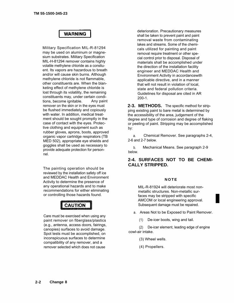
Military Specification MIL-R-81294may be used on aluminum or magne-sium substrates. Military SpecificationMIL-H-81294 remover contains highlyvolatile methylene chloride as a constiu-ent. Its vapors are hazardous to breathand/or will cause skin burns. Althoughmethylene chloride is not flammable,other constituents are. When the blan-keting effect of methylene chloride islost through its volatility, the remainingconstituents may, under certain condi-tions, become ignitable. Any paintremover on the skin or in the eyes mustbe flushed immediately and copiouslywith water. In addition, medical treat-ment should be sought promptly in thecase of contact with the eyes. Protec-tive clothing and equipment such asrubber gloves, aprons, boots, approvedorganic vapor cartridge respirators (TBMED 502), appropriate eye shields andgoggles shall be used as necessary toprovide adequate protection for person-nel.
The painting operation should bereviewed by the installation safety off iceand MEDDAC Health and EnvironmentActivity to determine the presence ofany operational hazards and to makerecommendations for either eliminatingor controlling those hazards found.
Care must be exercised when using anypaint remover on fiberglass/plastics(e.g., antenna, access doors, fairings,canopies) surfaces to avoid damage.Spot tests must be accomplished, oninconspicuous surfaces to determinecompatibility of any remover, and aremover selected which does not cause
deterioration. Precautionary measuresshall be taken to prevent paint and paintremoval waste from contaminatinglakes and streams. Some of the chemi-cals utilized for painting and paintremoval require treatment or other spe-cial control prior to disposal. Disposal ofmaterials shall be accomplished underthe direction of the installation facilityengineer and MEDDAC Health andEnvironment Activity in accordancewithapplicable directive, and in a mannerthat will not result in violation of local,state and federal pollution criteria.Guidelines for disposal are cited in AR200-1.
2-3. METHODS. The specific method for strip-ping existing paint to bare metal is determined bythe accessibility of the area, judgement of thedegree and type of corrosion and degree of flakingor peeling of paint. Stripping may be accomplishedby:
a. Chemical Remover. See paragraphs 2-4,2-6 and 2-7 below.
b. Mechanical Means. See paragraph 2-9below.
2-4. SURFACES NOT TO BE CHEMI-CALLY STRIPPED.
N O T E
a.
MIL-R-81924 will deteriorate most non-metallic structures. Non-metallic sur-faces may be stripped with specificAMCOM or local engineering approval.Subsequent damage must be repaired.
Areas Not to be Exposed to Paint Remover.
(1) De-icer boots, wing and tail.
(2) De-icer element, leading edge of enginecowl-air intake.
(3) Wheel wells.
(4) Propellers.
2-2 Change 8
TM 55-1500-345-23
(5) Propeller spinner or propeller control.
(6) Cockpit enclosures, including avionics pan-els, instruments, etc.
(7) Engine air intakes, tail pipe area. Batteryand fuel vents and heater exhaust must be covered tokeep out paint remover.
(8) Do not strip sealant presently applied underaccess covers. Any sealant removed will be replacedusing high adhesion sealant MIL-S-81733 Type II, ClassB or low adhesion MIL-S-8784 molded in the form of arubber gasket.
(9) Fiberglass wingtips and other .berglasscomponents, e.g., antennas and radomes.
b. Deleted
c. Radomes. Radomes will not be stripped.
2-5. PROTECTION OF SURFACES NOT TO BESTRIPPED.
a. General.
(1) Mask all transparent plastic surfaces suchas windows, canopies, blisters, etc. Plastic will becrazed, frost or lose transparency if paint removercomes in contact with them. Mask radomes in the samemanner as plastics to prevent damage to their rain-ero-sion resistant and antistatic coatings. Also, mask bootsor any exposed rubber or elastomer surfaces sinceremover will accelerate deterioration of these materials.Double masking of sensitive areas is recommended.
(2) Mask detailed decalcomania which cannotbe easily replaced. Other instructions, stencils or warn-ing signs will either be masked or replaced after repaint-ing.
(3) Do not attempt to remove coating from loopantennas. Protect the housing from contact with re-mover.
(4) Mask all faying surfaces, seams, accessdoors, pitot static ports (area within a one (1) inch di-ameter), or other openings with barrier paper and tape.
(5) All edges, repairs and loose fasteners on allhoneycomb panels shall be masked prior to chemicalstripping.
(6) Mask over joints, access doors, or otheropenings or panels which have been bonded with ad-hesives. Paint remover has a detrimental effect on thestrength of adhesives when allowed to contact them.
(7) Masking may be done with barrier paper,Military Specification MIL-B-131F or MIL-B-121, TypeI, Grade A, Class 1; tape, pressure sensitive adhesive,for masking during paint stripping, Military SpecificationMIL-T-23397, Type II (72 hour protection).
(8) Masking may also be done with paraffin wax,Federal Specification VV-W-95, in lieu of paper. Useonly masking tape, MIL-T-21595, to outline area to bemasked to keep wax off metal. Melt wax and brusha thick coat on surface. The temperature of the waxshould be approximately 150°F (65°C), as higher tem-perature may deform plastic.
b. Masking of Seams. Masking of seams can bedone with MIL-S-8784, Class B, sealant. Allow to cureto a firm rubbery state (approximately 20 hours at 60°Fto 80°F) prior to starting the stripping operation. Therequired cure time for this material must be consideredwhen flow or processing time is of prime importance.After the paint stripping operation is completed, the filletformed by the MIL-S-8784, class B, material shall bepeeled off by hand.
All masking or protective materials must be re-moved immediately upon completion of paintstripping and/or painting process.
2-6. GENERAL PREPARATIONS.
NOTE
The only chemical paint remover authorized foruse on aircraft surfaces is MIL-R-81294. Otherchemical removers cannot be used unless au-thorized by AMSAV-MEA.
Change 12 2-3
TM 55-1500-345-23
a. Preparation.
(1) Place aircraft on a wash rack, preferably ina shaded area, and attach a static ground.
(2) For best results, ambient temperatureshould be approximately between 50° and 100°F (10°and 37°C). Do not attempt to accomplish paint removalin rain, or on aircraft surfaces which are not dry.
(3) When painted surface is exceptionally dirtyor coated with fuel, oil, grease, mud, or other foreignmatter, clean it before applying remover in accordancewith paragraph 2-1.
b. Drying. After aircraft has been cleaned, allowsufficient time for surfaces and crevices to dry thor-oughly. Water remaining on surfaces and in creviceshas a detrimental effect on paint removers.
2-7. APPLICATION OF MIL-R-81294 PAINTREMOVERS.
Paint remover that is old is not necessarily un-satisfactory for use although it deteriorates pro-gressively with age in removal effectiveness,particularly if subjected to open air and temper-atures over 100 °Fahrenheit. More important,there is an increasing potential of corrosive-ness upon its aging. Close surveillance shall bemade of material age when it is to be used onaircraft surfaces. Any material which is ques-tionable by reason of age, or improper storage,shall be laboratory tested for continued confor-mance to specification, with particular referenceto the corrosive potential, prior to being used onaircraft surface. Any remover found not to be inaccordance with Military Specifications will bediscarded.
NOTE
Removers must be well mixed before use asthey tend to segregate on standing. Do thisby agitating with a wooden paddle if mechan-ical mixers are not available. Rolling a drumwill not mix its content very effectively. At tem-peratures below 60 °F, the removal power of re-movers will be noticeably slower than at highertemperatures.
a. Applying Removers. Beginning at the highestpoint of any vertical or sloping surface, apply a coat ofremover, with a long handle, nonmetallic brush. Barrelpump and spray gun may be used for application of re-movers. In no case should the spray be highly atomized.Agitate with a stiff fiber brush, if necessary, to loosenpaint. A wet film of remover should be maintained on thesurface being stripped to obtain efficient removal. Thismay require additional application of the remover. Areasshould be treated progressively, kept wet, and sufficienttime allowed for the stripping action. Best results areobtained by applying removers in shaded areas sincesunlight dries the remover quickly.
Prolonged breathing of remover fumes must beavoided. Use only in well ventilated areas.
NOTE
Deleted
b. Painted Surfaces. Enamel surfaces shouldwrinkle within 5 to 15 minutes after application. Mostsurfaces with lacquer or polyurethane paint will notwrinkle but will merely be softened by the remover;allow remover to remain 8 to 20 minutes, keeping awet surface by applying another coat of remover ifnecessary.
c. Cleanup of Stripped Surfaces.
2-4 Change 12
TM 55-1500-345-23
(1) Flush the stripped surfaces, using waterheated to 90° to 120° Fahrenheit at 150 to 250 psimaximum. If high pressure warm water is not avail-able, cold water at usual hydrant pressure may beused. This will require a longer time to accomplishthe washing. Lifted paint will be flushed by startingat the bottom and working upward, keeping theflushing liquids off the unwashed parts. After flush-ing thoroughly, continue cleaning in accordancewith TM 1-1500-344-23.
NOTE
Zinc chromate primed surfaces, wheretopcoat material has not been applied,should be washed down as soon aspossible after initial loosening of primer.If the surface becomes dry, anotherapplication of remover is required sincezinc chromate tends to become rede-posited on the surface.
(2) Tape and loosened paint may beremoved by hand or by using water under pressure.
2-8. STRIPPING IN CONFINED LOCA-TIONS.
a. Removal of Paint with Solvent Materials.When impractical to use emulsified paint removerbecause of complexities of assembly and rinsingdifficulties, remove acrylic paint with solvent materi-als such as ethyl acetate, Federal Specification TT-E-751, lacquer thinner, Federal Specification TT-T-266, or dichloromethane, Military SpecificationMIL-D-6998; remove polyurethane paint bymechanical means.
Prolonged breathing of solvent fumesmust be avoided. Use only in well venti-lated areas.
b. Application of Solvents
(1) After appropriate masking, apply sol-vents with soft bristle brush or clean cloth.
(2) Allow solvent to remain on surfaceuntil paint has softened and lifted. To keep the areawet with solvent, it may be necessary to keep a clothon the surface and keep the cloth saturated with sol-vent.
(3) Wipe all of the solvent away with aclean damp cloth, frequently rinsing cloth in cleanwater.
(4) Repeat steps (1) through (3) as nec-essary until all paint and residue have beenremoved from metal surface including recesses andaround rivets, bolts, etc.
(5) Wipe clean and dry with clean lint-freecloth, Federal Specification CCC-C-46.
2-9. MECHANICAL REMOVAL FROMMETALS. Mechanical removal of paint is recom-mended where chemical removal would be imprac-tical because of structural complexities, rinsing diffi-culties, or where it is more efficient or environmentalrestrictions on chemical exists.
a. Hand removal may be accomplishedusing:
(1) An abrasive nylon mat, Military Speci-fication MIL-A-9962; aluminum wool, Military Speci-fication MIL-A-4864, or Federal SpecificationP-P-101 No. 400 abrasive paper. Do not use steelwool.
(2) A hand operated air powered drillmotor with rotary brass wire brush or abrasive flapbrush on heavy structural non-clad aluminumalloys.
Change 8 2-5

TM 55-1500-345-23
The use of goggles or face shield ismandatory since paint particles canbreak loose and fly off.
Do not use steel brush or steel wool onnon-ferrous surfaces. Metal particleswill become embedded in the substrate,causing corrosion by galvanic actionbetween dissimilar metals.
(3) Wipe area with clean damp cloth fol-lowed by wiping dry, with a clean, dry lint-free cloth.Areas may be blown with warm oil-free air or gas-eous nitrogen.
Magnesium-Thorium Alloy Compo-nents of T-53, T-55 and T-63 enginescontain radioactive material. Themechanical method of corrosionremoval shall be attempted only underthe operating procedures required byTB 43-0108.
b. Abrasive Blasting. Abrasive blasting (a rapidmethod) consists of bombarding a surface with an
abrasive at high velocity. The abrasive may beglass beads, steel grit or organic materials and iscarried to the surface by air at high velocity. Thisshould not be applied on surface where criticaldimensions must be maintained or on thin struc-tures which can warp.
c. Wire Brushing. Wire brushing is a mechanicalabrasive operation done usually with a hand wirebrush or a wire brush mounted on a motor drivenwheel. By using different types of brushes and vari-ous lengths and gages of wire, a wide range of abra-sive action is possible. Use wire brushing to removeheavy corrosion and imbedded paint, especiallywhere chemical treatment is not practical. A typicalwire brushing procedure follows:
(1) Protect adjacent components from scale,chips, and dust.
(2) If grease or oil are present, clean area bymethod outlined in paragraph 2-1 or TM1-1500-344-23.
(3) Wire brush area to a firm metal subsur-face.
The use of goggles or face shieldis mandatory when using motor-driven brushes.
2-6 Change 8
TM 55-1500-345-23
2-10. SPECIAL CONDITIONS. Where diff culty isencountered on magnesium surfaces, paint may be re-moved by following instructions in Military Specif cationMIL-M-3171, Processes for Pretreatment and Preven-
tion of Corrosion on Magnesium Alloy. Do not blastf exible braided metal lines such as copper or stainlesssteel. Use only clean abrasive on Titanium Alloys.
SECTION III. METAL CONDITIONING2-11. METAL TREATMENT. Aluminum and magne-sium surfaces to be painted will be cleaned prior to paint-ing and prior to the application of the chemical treatmentspecif ed in paragraph 2-12 with a bristle brush usingany of the cleaning compounds or processes listed inTM 1-1500-344-23 series.
2-12. CHEMICAL COATINGS (CONVERSIONCOATINGS).
a. Chemical Treatment of Aluminum Sur-faces. Surfaces will be cleaned prior to application ofchemical coating. Chemical treatment of aluminum willbe as follows:
(1) General. Chemical surface treatment,such as alodine, provides a passive surface layer thatresists corrosion and provides a necessary base forbonding the paint to the aluminum.
(2) Materials. Treatment materials will con-form to Military Specif cation MIL-C-5541.
(3) Application.
(a) Prepare and apply in accordance withmanufacturer’s instructions. In general, mix 1-1/4ounces of compound with each gallon of water.
(b) Apply solution to perfectly cleaned butwetted surfaces.
(c) Apply solution liberally and evenly toonly as much surface at a time as can be coated andrinsed before surface treatment solution dries. Whenthe surface action appears complete on all areas, stopthe reaction by rinsing or f ooding the area with fresh,clean water. The reaction of the solution is stopped bydiluting the acid component. Be careful not to f ush the
solution into areas where it cannot be removed and/orfurther diluted by water. Accidental spills in conf nedareas can be neutralized using baking soda followedby rinsing with clean water. Allow the surface to drainand/or pick up the excess water by absorbing in asponge by blotting action; do not rub. Excess rubbingwill remove the coating since it is soft.
b. Chemical Treatment of Magnesium Sur-faces. Treat magnesium surfaces to be painted inaccordance with Military Specif cation MIL-M-3171.Apply strictly in accordance with manufacturer’s instruc-tions.
2-13. PRETREATMENT AND SEALING OF BAREMETAL SURFACES.
a. Aluminum bare metal will be alodine treatedper MIL-C-5541, Class 1A, prior to applying the f rstprimer.
b. Bare magnesium metal areas will be dichro-mate treated per MIL-M-3171, Type 6, prior to applyingthe f rst primer.
NOTE
Paint will not bond to the brown powdery surfaceof excessively treated magnesium or aluminum,nor will paint bond to treated aluminum surfaceswhich are too dark.
c. Steel substrates will be treated with zinc phos-phate per TT-C-490, Type I, prior to applying the f rstprimer.
d. All missing or deteriorated skin sealant will bereplaced using low adhesion, corrosion inhibiting AMS-3265 sealing compound.
Change 11 2-7/(2-8 blank)


TM55-1500-345-23
C H A P T E R 3
P A I N T I N G : G E N E R A L
Section l. PAINTING TECHNIQUES
3 - 1 . S T O R A G E O F P A I N T I N G M A T E R l -ALS. To prevent fire, spoilage, and waste arisingfrom improper storage and surplus stock, thefollowing precautions shall be observed.
Space heaters or other direct firedheaters shall not be used to heatstorage areas. Floors should be con-crete and drained to one point; drainshall run to sump or detached cisternand have deep trap. Ventilation shallutilize screened inlets 6 inches abovefloor and screened vent through roof.
a. Paint and thinners shall be stored wherepossible in dry, fire resistant well drained and wellventilated structures, preferably separated fromother buildings, and under automatic sprinklerprotection.
b. To avoid possible leakage arising fromcorrosion of containers, protection shall be pro-vided against wetting by rain, snow, steam leaks,or other sources of water.
c. Materials shall not be stored in the prox-imity of steam lines or other sources of heat toavoid direct heat. It is recommended that steamheat be used with coils above stock and screenedto prevent contact with drums or containers.
d. Storage shall not be on floors below gradeand first tier of containers shall be laid at least 2inches above floor level to provide for suitableventilation and drainage. Sills shall be provided atopenings to storage areas, approximately 6 in-ches above floor
e. Paint components and thinners packagedin 55 gallon steel drums may be stored outdoorsprovided containers are protected against rustingby painting of bare metal areas and are set ondunnage so as to provide approximately 2 inchesclearance above ground. Drums stored out ofdoors shall be laid on their sides to protect loss ofmarkings stenci led on the heads throughweathering action of rain, snow, and sun.
f. Handling of stock shall be conducted in amanner to avoid damage to labels. Relabeling ofmaterial where labels have been obliterated mayresult in mislabeling, with consequent incorrectuse or waste of material. Materials with obliterat-ed labels should be properly discarded.
g. Care should be taken to assure protectionof the paint or components from moisture. Par-ticular care should be exercised to prevent waterentering containers as paint is opened.
h. Containers of paint materials shall bereadily accessible at all times. Other materialsshall not be stacked on top of paint materials.
i. Containers shall be stored and issued inorder of dates of manufacture shown on respec-tive labels. Materials bearing oldest date shall beused first In the event that date of manufacture isnot shown on container, date of receipt shall beconsidered as approximate date of manufacturefor purposes of storage and issue.
j. To give best results, temperature of paintmaterials should be between 60° and 85° F (18°and 29° C) at time of use. Storage conditions thatresult in paint temperatures below 55° F (13° C) orabove 95° F (35° C)room temperatureprior to use.
require storage of material atfor approximately 25 hours
3-1

TM55-1500-345-23
k. Transit and Storage - In closed containers,temperature and humidity will not affect thestability of either component of two part coatings.Both components will remain stable for 1 year, aslong as the component B, the catalyst portion, re-mains in closed and sealed containers. Where it isnecessary to extract a portion of the component B,it should be done in a cool location and the lidresealed as rapidly and as tightly, as possible.
3 - 2 . S A F E T Y A N D H E A L T H A S P E C T SOF PAINTING.
C A U T I O N
Federal and state environmental regula-tions are applicable to all chemicals us-ed in painting processes. Precautionarymeasures shall be taken to preventpaint and paint removal waste from con-laminating lakes and streams. Some ofthe chemicals utilized for painting andpaint removal require treatment or otherspecial control prior to disposal. Dispo-sal of materials shall be accomplishedunder the direction of the installationfacility engineer and MEDDAC Healthand Environmental Activity in accor-dance with applicable directives, and ina manner that will not result in violationof local, state and federal pollutioncriteria. Guidelines for disposal arecited in AR 200-1.
Painting operations present hazards that requirecontrol or preventive measures. Vapors produced,particularly in spray painting, are highly flam-mable, as are the accumulated dried coatingmaterials deposited on walls, floor and equipmentin painting areas. Coating materials and theirthinners very often contain toxic substanceswhich are injurious to health by inhalation and, toa less degree, by physical contact. Paintingoperations also involve hazards resulting from theimproper use of work stands, ladders, hoists, etc.All painting personnel shall take all requisite safe-ty precautions with regard to toxicity and other
health hazards, and flammability hazards in ac-cordance with existing instructions and regula-tions. All safety precautions regarding personnelhealth, fire prevention, ventilation, handling ofequipment, electr ical grounding, storage o fcoating materials, area preparation, use of vapor-proof lights, etc., are mandatory.
a. Personnel Safety Measures. The followingmeasures are minimum requirements for personalsafety.
(1) Wear protective clothing to preventcontamination of ordinary clothing.
(2) Aprons and clothing that becomesaturated with paint should not be worn in shop.Saturated clothing shall not be hung in lockers orother similar confined spaces that might inducespontaneous combustion.
(3) Al l personnel should wear non-sparking shoes, which are free from metal nails insoles and heels.
(4) Full skin covers, i.e., gloves or skinprotective creams shall be applied to exposedskin areas prior to painting to guard against in-jurious effects of paints, and to allow readyremoval of paints by washing the area with water.Skin areas shall be clean and dry before cream isapplied.
W A R N I N G
Certain paint solvents and pigmentsmay cause dermatitis on coming in con-tact with the skin. Some solvents maypenetrate skin, or may be inhaled asvapors, and lead to systemic poisoning.Care must be taken to avoid skin con-tact or breathing vapors to avoid sys-temic poisoning.
(5) Personnel engaged in stripping orCleaning with methylethylketone (MEK), acetoneor toluene and spray application of paints shallwear an approved organic vapor cart r idg erespirator approved by the Operational Safety andHealth Administration (OSHA). (See Tables 8-7through 8-9).
3-2 Change 4
TM 55-1500-345-23
(6) Wash thoroughly after painting and beforeeating, and do not carry food into spraying areas.
(7) Spray paint only when adequate exhaust orgeneral ventilation is available.
(8) Personnel having histories of skin or respi-ratory ailments should be excluded from paint crewsapplying two component polyurethane or epoxy paints.When there is doubt, appropriate medical tests must beadministered.
(9) Individuals who engage in mixing or apply-ing plural component paints containing isocyanates willbe subjected to appropriate pre-placement surveillanceand periodic job related medical tests.
b. Fire Precautions. Most aircraft paints containhighly .ammable constituents, which, under suitableconditions, can form explosive mixtures with air. As aresult, the following precautions shall be taken:
(1) Electric motors used to drive exhaust fansor other equipment in storage places shall be of the typeapproved for explosive atmospheres. If such motors arenot available, substitutes shall be located outside theroom or building. Motor housing, fan frames, and thelike shall be properly grounded to prevent possible staticsparks, and all electric wiring shall be enclosed in con-duits.
(2) All electric lights bulbs used within storagearea shall be enclosed in vaporproof globes, mountedin keyless sockets.
(3) Motor starting devices and switches in allelectrical circuits, if not of the explosive-proof type andapproved by an established electrical underwriter, shallbe located outside room or building to prevent fire haz-ards from flammable vapors.
(4) Tools used to open containers shall be non-spark-producing types. All electrically-driven portabletools used in this area shall be explosion proof and prop-erly grounded.
(5) Ample fire extinguishers of the foam, drychemical, or carbon dioxide type will be provided.
Containers of paint may develop internal pres-sure during storage and should be opened cau-tiously.
c. Opening of Containers. Paint containers maydevelop internal pressure due to storage at high tem-peratures or by development of gas due to deterioration.This condition may be detected by a bulging of light gagesteel drums. Containers must be opened slowly to allowthe pressure to escape before completely removing theseal.
NOTEFailure to follow this procedure may result inpaint being spattered on personnel and sur-rounding areas.
(1) Open containers, sealed with bungs, byslowly turning bung out until a hissing sound is heard.When hissing stops (an indication that pressure in andout of drum is equal) completely remove bung.
Use a fine, nonspark-producing tool and a soft-head hammer (rubber or plastic) to puncturedrum.
(2) Containers which are bulged or distorteddue to internal pressure shall have a small hole punc-tured in top to release pressure. After pressure isreleased, container may be opened in usual manner.
3-3. ATMOSPHERIC CONDITIONS FORPAINTING.
a. Coatings normally should not be applied un-der unfavorable atmospheric conditions such as wind,strong drafts, dust, high humidity or extremes of tem-perature.
3-3

TM 55-1500-345-23
b. Specific guidance on ambient temperature andhumidity ranges for painting with various coatings maybe found in other parts of the TM, in the applicable spec-ifications, or in the manufacturer’s recommendations. Ifnot specific guidance is given, the general guidance isto not paint below 50°F or above 90°F, nor below 40%or above 75% humidity.
c. The temperature of the surface to be paintedmust also be considered, and work schedules adjustedto allow or induce surface(s) to come to the proper tem-perature before applying paint.
3-4. SURFACE CONDITION. Prior to painting, in-spect or test all metal surfaces for cleanliness andphysical condition suitable for receiving paint material.
a. The water break test is a method of evaluatingthe degree of cleanness of a metal surface. It is basedon the ability of a clean surface to sustain an unbrokenfilm of water. Test representative areas of the surfaceto be painted by projecting distilled water, deionized (DI)water, or reverse osmosis (RO) water that complies withASTM D1193 Type I, II, III, or IV on it using an atomizingdevice such as a nasal atomizer. Do not use a paintsprayer for this purpose as the excessive pressure willdefeat this test. If water gathers into separate dropletswithin 25 seconds (that is, if the surface shows a waterbreak) the surface has failed the cleanness test. If, onthe other hand, the water suddenly flashes out into a filmover a large area, an impurity such as alkali detergent,etc., is on the surface and it has failed the test. If thewater merges into a continuous film without a suddenflashout, the surface has passed the water break test.A solvent wipedown is not required if the surface haspassed a water break test.
b. Insufficient rinsing after cleaning may leave anunacceptable surface. For best adhesion of coatings,metallic surfaces should give either a neutral or a slightly
acid reaction when alkaline cleaners are used. Moist-ened red litmus paper when applied to the surface shallnot react by turning blue. If such color changes occur,apply a 0.20 to 0.25 percent chromic acid O-C-303 so-lution until a piece of blue litmus paper applied to thetreated surface turns red, which indicates an acid sur-face. Permit the acid solution to remain on the surfacefrom two to five minutes. Follow with a water rinse andthen wipe dry with clean, lint-free cloths.
c. Determine whether the surface has appropriatesurface treatment in accordance with TM 1-1500-344-23Series.
d. When a special solvent cleaning requirementexists in aircraft painting operations, use Military Speci-fication, MIL-D-16791, TYPE 1, general purpose deter-gent, consisting of 1/2 ounce of detergent in a gallon ofwater for wipedown. Then wipedown the aircraft withisopropyl alcohol, TT-I-735. Additionally, each time thepainting sequence of an aircraft is broken overnight orlonger, this same procedure shall be performed immedi-ately prior to application of further coats to insure clean-ness and proper paintability of the surface.
e. Examine for presence of corrosion or foreignmatter retained in seams and crevices, etc, and for oilyfilms or deposits which may have accumulated aftercleaning. If any of these are present, remove or treatas directed in TM 1-1500-344-23 Series.
f. Assure that all metal surfaces and all seams andcrevices are dry prior to application of paint. Pressurizedfiltered air may be used to dry these areas.
g. Non-metallic surfaces should be dry, free ofcontamination; all pores sealed and scuff sanded withan abrasive nylon mat in accordance with Military Spec-ification MIL-A-9962.
3-4 Change 12

3 - 5 . M A T I N G S U R F A C E S . assembly.adhesively
a. Application, Similar Metals. All seams in processed
TM55-1500-345-23
Faying surfaces that are to bebonded will be surface treated andas specified in the approved bonding
which the mating (faying) surfaces are similar procedures prescribed for the assemblies con-metals will be protected by applying two coats of cerned. In addit ion to the required pr imerprimer to each surface being joined. Welded fay- coatings, faying surfaces of magnesium alloysing surfaces shal l not be pr imed pr ior to will be filled with an approved sealing compound.
Change 1 3-4.1/(3-4.2 blank)

TM 55-1500-345-23
b. Application, Dissimilar Metals. Each surfaceto be joined will receive a minimum of two coats of theappropriate primer, and, in addition, the following pre-cautions will be taken.
(1) Where magnesium is one of the metalsof dissimilar metal faying surfaces, the metals will beseparated by use of an approved barrier tape. The tapewill extend not less than 1/4 inch beyond the joint edgesto prevent moisture from bridging between the dissimi-lar metals. Sealing compounds conforming to MilitarySpeci.cation MIL-S-81733 may be used as moisturebarriers in lieu of tape and when used, the sealingcompound will be applied between the surfaces andsqueezed out of all boundaries and the excess removedin a manner that will fillet all edges. The fillet width willbe not less than 1/4 inch. Joint areas which would retainwater will be filled with a sealing compound conformingto Military Specification MIL-S-81733 or MIL-S-7124.When the use of a barrier tape or sealing compound isimpractical because of mechanical or other factors, aprimed 5356 aluminum alloy shim extending 1/4 inchwill be used in lieu of the tape or sealing compound.
(2) Butt joints consisting of a riveted magnesiumsheet and a riveted dissimilar metal sheet will be pro-tected by grooving the seam to a width of not less than1/8 inch and filling with sealing compound conformingwith Military Specification MIL-S-81733. The depth ofthe groove will be sufficient to retain the sealing com-pound conforming to Military Specification MIL-S-81733,which will be subsequently applied and smoothed flushwith the surfaces of adjacent dissimilar metals.
(3) Butt joints consisting of a magnesium sheetand a dissimilar metal sheet, either of which is securedby mechanical means other than riveting, will be pro-tected by use of an approved adhesive barrier tape ora primed 5052 aluminum alloy foil which covers the cutends of either or both dissimilar metal sheets and ex-tends not less than 1/4 inch beyond the joint edge.
(4) Organic adhesive barrier tapes or metal foilswill not be used on exterior surfaces.
c. Attaching Parts. Parts, such as nuts, bushings,spacers, washers, rivets, high-shear rivets, screws, self-tapping screws, sleeves for "shakeproof" fastener studs,self-locking nuts, "speed nuts", clamps, and the like, donot need to be painted in detail except when dissim-ilar metals or wood contacts are involved in the ma-terials being joined. Such parts will receive a coat ofepoxy primer, MIL-PRF-23377 (wet or dry, at installa-tion). Rivets (5066) in magnesium alloy need not beinstalled with epoxy primer. For magnesium dissimilarcombinations follow the general requirements of para-graph 3-5. Close tolerance bolts passing through dis-similar metals will be coated before installation with azinc chromate compound conforming to Federal Speci-fication TT-P-1757, or a wet epoxy primer in accordancewith Military Specification, MIL-PRF-23377. Aluminumalloy washers (5356) of suitable design will be used un-der machine screws, countersunk fastners, boltheads,and nuts that would otherwise contact magnesium.
3-6. MASKING. Masking of specific areas is requiredin painting operations on large assemblies or structureseither for protective reasons, as in the precautionarynote below, or for purposes of delineation.
a. Mask areas such as windows, canopies andlarge openings with combinations of barrier materials.
(1) Federal Specification MIL-B-121, usually atreated paper which is oil and moisture resistant.
(2) Federal Specification MIL-B-131, usually alaminated foil and cloth or foil and paper with good watervapor resistance.
NOTE
Both types above are heat sealable.
(3) Crepe-backed paper masking tape, MilitarySpecification MIL-T-21595, Type I.
b. Cover small or regularly shaped parts with tapealone.
Change 12 3-5

TM 55-1500-345-23
c. In repetitive spraying of the same or similarstructures, it is advisable to have available pre-designedbandages, socks, etc., of barrier paper or cloth.
d. Avoid using tape in such a way as to leave apaint edge on aerodynamic surfaces unless featheringby sanding can be done safely.
e. Use only approved masking tapes in varyingwidths required by the job. A complex or curved areais better masked initially at the paint edges with narrow(1/2 inch) tape. Wider tape may then be applied overthe narrow, if required.
f. Use only approved masking paper for large areamasking. Coating solvents may dissolve and depositprinting ink from newspapers, etc., on the surface of thearea being masked; hence, such materials should beavoided as masking materials.
g. When spray painting, mask or cover surfacesat a distance from the area being painted which mightreceive over-spray or paint drift.
h. Masking tapes should be removed as soon aspossible after coating application.
i. Press tape firmly at the masking edge when ap-plying it to prevent paint bleeding under it by capillaryaction.
NOTE
Care should be taken to insure that paint is notapplied to certain surfaces where paint will in-terfere with a function. The following should bemasked or otherwise protected during painting:Machined surfaces that move with respect toeach other such as threads, slip rods, bearingcontacts and gear teeth; electrical parts, suchas contacts, relays, insulators, sockets, plugs,connectors, wiring and terminals; plastic andrubber (natural and synthetic) mounts, spacers,etc, and lubrication fittings, cups, oil holes, etc.Do not paint interior of bomb racks or other actu-ators except as noted on manufacturer’s draw-ing.
3-7. MIXING.
a. Painting materials shall be prepared for appli-cation under dry and clean conditions with dry and cleanequipment.
b. Paint shops shall be equipped with continuousmechanical paint agitators of suitable capacity. Theproper sequence for preparing packaged materials priorto each use is as follows:
(1) Allow materials to come to room tempera-ture.
(2) Remove lids and inspect contents for ski-nover, gelling, lumps, etc. Skins, if present, shall becarefully removed and discarded, retaining liquids whichdrain from them. Gelled, lumpy or otherwise deterio-rated paints shall not be used, but properly discarded.
NOTE
Cans of the pigmented component of MIL-DTL-64159 or MIL-DTL-53039 paint with non-reseal-able lids should not be opened and inspecteduntil after the original mechanical agitation, ifpractical.
(3) Thoroughly agitate all component contain-ers, using a mechanical agitator prior to mixing or thin-ning and again prior to and during application. Agitationmust be continuous during application to assure unifor-mity of pigment.
c. Use automatic mixing and proportioning de-vices, if possible. When automatic equipment is notavailable, mix paint as follows:
(1) Breakup sediment remaining in original con-tainer with a clean wood or metal paddle; stir until asmooth, uniform, heavy paste forms.
(2) Proportion paint in clean mixing container tothe four to one ratio specified. (This applies only toMIL-DTL-64159 or MIL-DTL-53039. Respirator must beworn.
3-6 Change 12

TM 55-1500-345-23
(3) Catalytic action begins immediately on mix-ing. An eight hour pot life can be anticipated after mix-ing. Ideally, mixed paint should be used in six hours, toassure the capability for complete system purging andcleaning to precluded equipment damage.
(4) Assure complete mixing when manual mix-ing is used.
(5) To avoid the possibility of incompatibility ofmaterials under the same specification but of differentmanufacturers, such materials shall not be mixed.Primers and topcoats from different manufacturers,under the same specification, will not be mixed, butmay be applied separately to areas which are to beover-coated. Every effort shall be made, however, toassure that an entire topcoat is restricted to the productof a single manufacturer and, where possible, to thesame batch in order to maintain uniformity of color,finish, etc.
(6) Application and mixing equipment must bethoroughly purged and cleaned after use.
Mixing should always be done in areas that arewell ventilated and away from any source ofopen flame.
3-8. THINNING.
a. When thinning is necessary, always add thinnerto the coating material. Adding coating material to thin-ner may result in an irreversible separation or degrada-tion of some of the coating ingredients. Thinner shouldbe added slowly with continual stirring to obtain com-plete mixing. For all thinning, use only thinners autho-rized in applicable instructions in this technical bulletinor pertinent specifications or, in the absence of theseinstructions, those recommended by the manufacturer.MEK can be used in cold weather. Other thinners maybe needed in hot weather.
METHYL ETHYL KETONE
Keep away from heat and open flame.
Keep container closed.
Use with adequate ventilation.
Avoid prolonged breathing of vapors.
Avoid prolonged or repeated contact with skin.
Failure to observe these precautions can result in seri-ous injury or systemic poisoning of personnel.
NOTE
The wrong thinner may destroy certain charac-teristics of a coating material without immedi-ately giving visual evidence in the wet state.
Reduced material which has increased in viscosity dueto evaporation will require corrective additions. How-ever, some coating materials which undergo chemicalprocesses, such as polymerization to create a film, can-not be thinned beyond a certain point and remain us-able; nor can they be brought back to the correct viscos-ity by thinning after the chemical action has progressedbeyond a critical point. This is the case with epoxy andpolyurethane.
b. Thinning shall be controlled by weight, volumeor viscosity measurement to obtain and maintain properand uniform consistency. If there is no specification cov-ering the material, thin according to manufacturer’s in-structions.
NOTE
Do not mix materials of the same specificationbut supplied by different manufacturers duringapplication. This will avoid problems of incom-patibility in the liquid and curing phases.
c. Strain all material to be used in spray equip-ment through clean 60-90 mesh metal strainers in accor-dance with paint or equipment manufacturers instruc-tions.
3-9. APPLICATION EQUIPMENT.
a. Application Systems. The application equip-ment plays a key role in the overall success of paintingaircraft and aircraft components. Selection of ap-plication systems and care thereafter are essentialconsiderations in the painting process, whether thesystem is an automated (robotics) or a manual type.No description or details are provided herein becauseof the wide variances
Change 1 3-7

TM 55-1500-345-23
between equipment manufacturers and local conditions.Each manufacturer’s instructions and other details mustbe consulted. Special consideration should be givenequipment with which plural components are to be ap-plied. Problems may be encountered, i.e., required ac-curacy of mixtures, pot life of mixtures and effects result-ing from non-adherence to prescribed application proce-dures.
b. Components of Application Equipment.
(1) Automated Systems (Robots). Such sys-tems include, but are not limited to, metering and mixingequipment, air compressors, air cleaners, electrostaticgenerators, spray booths, feed lines and tanks, regula-tors and computerized automated components.
(2) Hoses. Because of friction losses in hoses,it is essential that the proper sizes be used. Do notuse hoses longer than 50 feet except in the case ofhigh pressure air hoses leading to the regulator or tank.These may be a maximum of 150 feet for painting suchareas as the tail surfaces of exceptionally large aircraftwhich are of considerable height above the ground. Ex-tra lengths of hose may be attached for this use butshould be removed when no longer needed. The highpressure air hose should have a minimum inside diam-eter of 7/16 inch. No less than 3/8 inch ID fluid hoseshould be used from the tank to the gun and no less than5/16 ID air hose from the regulator to the tank and fromthe tank to the gun. Any reduction in size or increasein length from the forestated may produce unsatisfac-tory results. Air and paint hoses are furnished in variousstandard lengths. Determine the length required for usein a spray booth measuring the width of the booth andadd two feet for the total required length of the hose.
Hoses should always be thoroughly cleaned bypurging and flushing with solvent appropriate tothe coating material used. When the material isa catalytic system (epoxy or polyurethane), thismust be done immediately after use and beforethe prescribed pot life limit has been reached toprevent the material from gelling in the system.
(3) Associated Electrical Equipment. As re-quired by manufacturers.
(4) Spray Guns, for Manual Applica-tions. MIL-DTL-64159 or MIL-DTL-53039 paints shallbe applied only in approved and qualified facilities. Noapplication of MIL-DTL-64159 or MIL-DTL-53039 shallbe accomplished in open air. Interior applications ofMIL-DTL-64159 or MIL-DTL-53039 paint will be accom-plished using personal respirator masks and equipmentprescribed in Table 8-6.
Personal protective clothing, and dispositionthereof, should also conform to OSHA andNIOSH safety specifications.
(5) Paint Booths and Application Equip-ment. No description or detail is provided for paintingfacilities due to the variance of equipment and localconditions. Such equipment must, however, conformto conditions of Tables 8-6 through 8-8. For automatedrobotic equipment, manufacturer’s instructions shouldbe consulted.
(6) Paint Brushes. Paint brushes should beused during touch-up procedures in open air whenapplying MMIL-DTL-64159 or MIL-DTL-53039 paint.Consult section on touch-up procedures for details.
3-10. PAINT SPRAY GUN TECHNIQUES. Whenmanual spray applications are employed, techniquesmust be used which insure the most uniform and properdry thin coating. Spray guns (and spray coatings) aredesigned to be used with certain spraying techniques.Quality of finish will depend on how well these tech-niques are used. Spraying techniques include thefollowing:
a. Distance. Depending on the desired width ofthe spray pattern, the gun is held six to ten inches fromthe work (figure 3-1). If all other adjustments are cor-rect, greater distance will result in dry spray or dustingand excessive over spray. Holding the gun too close tothe work will result in coatings which are too heavy andwill have a tendency to sag or run.
b. Stroking. The essence of proper stroking ismaintaining the same distance of the gun from
3-8 Change 12

TM 55-1500-345-23
Figure 3-1. Right and Methods of Spraying
the work, the same speed, and as near to a right angle tothe surface as possible throughout the entire pass. Thenatural tendency for spray painters, particularly when fa-tigued or in an uncomfortable position, is to arc or wavethe gun (figure 3-1). This practice must be avoided at allcosts. In general, wrist movement must be eliminated instroking. A flexible wrist almost inevitably causes thegun to describe a curve instead of remaining parallel tothe surface. This causes a thicker coating to be appliedin the middle of the stroke than at the end. (An excep-tion to the rules is in spotting during touchup. Here itis permissible to fan the gun to lay down a spot whichis thinner at the edges in order to blend into the largerpainted area.) Touch up here applies only to paintingoccurring in an approved facility and not open air touchup. Special pains must be taken, particularly when ap-plying dense coating materials with poor flow character-istics (such as MIL-DTL-64159 or MIL-DTL-53039), that
the gun is held perpendicular to all surfaces (flat or con-toured as they are passed).
If this is not done, the irregular spray pattern formedwill lay down uneven thicknesses. Uneven thicknesswill cause uneven drying when using single componentpaint. Uneven thickness, when MIL-DTL-64159 or MIL-DTL-53039 paints are used may cause sagging. Pro-trusions such as screw heads, etc., present surfacesthat will require facing the gun in several directions tocompletely coat them. It may be advisable to spot paintthese in advance. The rate of the stroke should be uni-form and such as to lay down a full wet coat of material.Stroking should be in parallel passes with each strokeaimed for a 50 percent overlay, or so that the middle ofthe spray strikes the wet bottom edge of the previousstroke (figure 3-3.)
Change 12 3-9
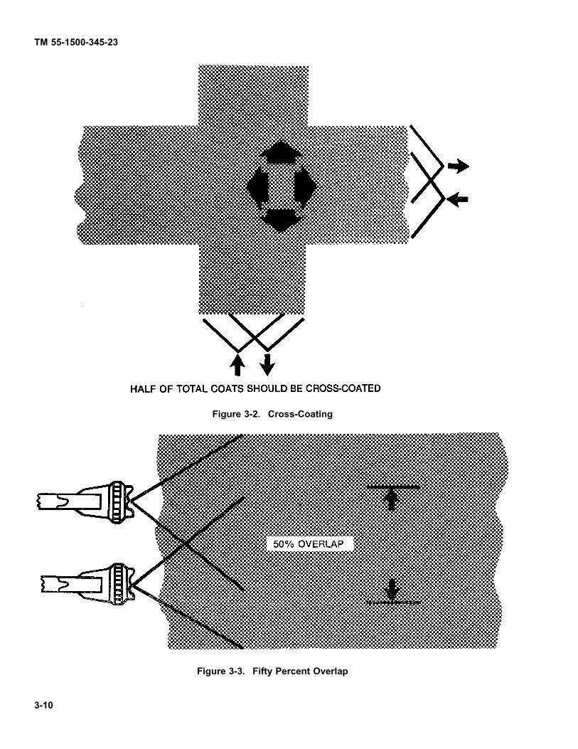
TM 55-1500-345-23
Figure 3-2. Cross-Coating
Figure 3-3. Fifty Percent Overlap
3-10

TM 55-1500-345-23
c. Triggering. Proper triggering of the gun is dif-ficult to learn and can only be developed by practice.It is a matter of judgement and sensitivity of touch andvariations of triggering technique may be called for inspecial situations. In general, the painter should beginhis stroke before triggering the gun and release the trig-ger before stopping the stroke. It is intended to featherout the end of a stroke so that the end of a succeedingoverlapping stroke will blend into it. Examine of correcttechniques are shown in figure 3-1.
NOTE
A reasonable amount of care will maintain sprayguns and spray equipment in top operating con-dition and prevent a majority of spraying diffi-culties. Thorough cleaning immediately afteruse and appropriate lubrication of equipmentare essential. Care should be taken to not allowgelling to occur for any particular mixed batchof plural component paint. The system shouldbe purged and flushed after use of each mixedbatch to avoid system stoppages, and batchmixes.
d. Setting Spray Pattern. See Fig 3-4 for recom-mended adjustments.
3-11. PAINTING DIFFICULTIES AND REMEDIES.
a. Coating troubles may be divided into sixgroups: (1) Inadequate surface preparation (includingtemperature), (2) incorrect methods or techniques ofapplication, (3) unusual and unsuitable climatic andatmospheric conditions, (4) unsuitable and improp-erly adjusted equipment, (5) faulty finishing materialor improperly mixed or agitated components and (6)systems not purged of previously mixed materials. Anexperienced finisher may be capable of adjusting toobtain proper results with faulty materials, but this isan emergency measure only and must be with thecognizance and authority of the quality control facil-ity. The practice is not advised. Incorrect methods ofapplication should be discontinued upon discovery of
the discrepancy. Areas painted prior to the discoveryof such discrepancies must be inspected and remedialmeasures taken when necessary. Brushing and rollercoating on certain surfaces must be used in confinedareas. Remedying incorrect applications, however,also calls for training. The practice of allowing inade-quately trained personnel to apply MIL-DTL-64159 orMIL-DTL-53039 coatings, particularly to aeronauticalsurfaces, is unauthorized and dangerous. Unusual orunsuitable climatic and atmospheric conditions are nor-mally not a problem since manual spray painting mustbe accomplished in an approved facility which usuallycompensates for such conditions. Unsuitable or faultyequipment can only be remedied by obtaining properequipment or repair. Table 3-1 shows common troublesof spray coating operations with suggested remedies ormethods of avoidance.
b. Faulty spray patterns and suggested correc-tions are shown in Fig 3-5.
c. Blushing of coatings is the result of water con-densation from the atmosphere within, or on, an appliedorganic film. It occurs when the temperature of the worksurface falls below the prevailing dewpoint. (It shall al-ways be looked for in production coating whenever otherthan average atmospheric conditions prevail). It showsas a lighter-than-normal or bleached discoloration or in-creased opaqueness of the film. It may occur to the ex-tent that a surface powder develops which can be re-moved by fingernail or by light rubbing. (Rubbing willnot cure the condition). It may be almost impercepti-ble, and blushing inducing conditions may escape noticeon test panels sprayed prior to production coating dueto the temperature differences between test and pro-duction environment. Though MIL-DTL-64159 or MIL-DTL-53039 painted items are not susceptible to wateror moisture damage immediately after proper applica-tion to items. Great care must be taken to avoid surfacecondensation prior to coating or water induction, in anyform, into unmixed components or the mixture prior to orduring application. Water will not affect the cure processafter proper application. Water will affect paints otherthan plural component catalytic paints.
Change 12 3-11

TM 55-1500-345-23
Figure 3-4. Setting Spray Pattern.
3-12. FILM THICKNESS (AIRCRAFT SURFACES).
a. Film applied either too thick or too thin will havereduced effectiveness in service. (See MIL-DTL-64159or MIL-DTL-53039 for recommended film thickness ap-plicable to standard coatings for aircraft. Recommendedminimal dry film thickness is 1.8 mils). Attaining propercoating thickness by spraying is a matter of technique,plus periodically checking the work. There is a limit tothe thickness that can be applied at one pass because ofpossible sagging of the film, and often this must be con-sidered in obtaining the ultimate desired thickness of allpaints. Also, there is a tendency with coating materialsof good hiding power to increase the spreading rate asthe work progresses and this must be curbed. Changing
atmospheric conditions, during operations, may have tobe compensated for in order to continue applying a uni-form film. Frequent checks with a wet film thicknessgage, if available, should be made during painting toascertain and control film thickness. Thickness cannotbe gaged accurately without instruments, but, lackingthese, the best assurance of consistent films is in cor-rect initial adjustment of gun and material and the use ofgood judgement.
NOTECare should be taken that proper measure-ments are made when extremely rough tex-ture paint is applied, e.g., MIL-DTL-64159 orMIL-DTL-53039 aircraft green.
3-12 Change 12

TM 55-1500-345-23
PATTERN CAUSE CORRECTION
(A) DRIED OUT PACKING AROUND MATERIALNEEDLE VALVE PERMITS AIR TO GET INTO FLUIDPASSAGEWAY. THIS RESULTS IN SPITTING.(B) DIRT BETWEEN FLUID NOZZLE SEAT AND BODYOR A LOOSELY INSTALLED FLUID NOZZLE WILLMAKE A GUN SPIT
TO CORRECT CAUSE (A). BACK UPKNURLED NUT C, PLACE TWO DROPSOF MACHINE OIL ON PACKING, REPLACENUT AND TIGHTEN WITH FINGERS ONLY.IN AGGRAVATED CASES, REPLACEPACKING.
(C) A LOOSE OR DEFECTIVE SWIVEL NUTONSIPHON CUP OR MATERIAL HOSE CAN CAUSESPITTING.
TO CORRECT CAUSE (B), REMOVEFLUID NOZZLE D, CLEAN BACK OFNOZZLE SEAT IN GUN BODY USING RAGWET WITH THINNER, REPLACE NOZZLEAND DRAW UP TIGHTLY AGAINST BODY.
TO CORRECT CAUSE (C), TIGHTEN ORREPLACE SWIVEL NUT E.
FAN SPRAY PATTERN THAT IS HEAVY IN THEMIDDLE, OR A PATTERN THAT HAS AN UNATOMIZED"SALT-AND-PEPPER" EFFECT INDICATES THAT THEATOMIZING AIR PRESSURE IS NOT SUFFICIENTLYHIGH.
INCREASE PRESSURE FROM YOUR AIRSUPPLY. CORRECT AIR PRESSURESARE DISCUSSED ELSEWHERE IN THISINSTRUCTION SHEET.
DRIED MATERIAL IN WINGPORT "A" RESTRICTSPASSAGE OF AIR THROUGHIT AND PRODUCES ACRESENT FULL PRESSUREOF AIR FROM CLEAN WINGPORT FORCES PATTERN INDIRECTION OF CLOGGEDSIDE.
DISSOLVE MATERIAL IN SIDE PORT WITHTHINNER. DO NOT POKE IN ANY OF THEOPENINGS WITH METAL INSTRUMENTS.
SPRAY PATTERN WIDER ORHEAVIER AT EITHER END ISCAUSED BY DRIED MATERIALAROUND THE OUTSIDE OFTHE FLUID NOZZLE TIP. BRESTRICTS THE PASSAGEOF ATOMIZING AIR ATONE POINT THROUGH THECENTER OPENING OF AIRNOZZLE AND RESULTS INPATTERN SHOWN. THISPATTERN CAN ALSO BECAUSED BY LOOSE AIRNOZZLE.
IF DRIED MATERIAL IS CAUSING THETROUBLE, REMOVE AIR NOZZLE ANDWIPE OFF FLUID TIP, USING RAG WETWITH THINNER. TIGHTEN AIR NOZZLE.
Figure 3-5. Faulty Patterns and Suggested Corrections (Sheet 1 of 2)
Change 12 3-13

TM 55-1500-345-23
A SPLIT SPRAY OR ONE THATIS HEAVY ON EACH END OFA FAN PATTERN AND WEAKIN THE MIDDLE IS USUALLYCAUSED BY (A TOO HIGH ANATOMIZING AIR PRESSURE,OR (B) BY ATTEMPTING TOGET TOO WIDE A SPRAYWITH THIN MATERIAL.)
REDUCING AIR PRESSURE WILLCORRECT CAUSE (A). TO CORRECTCAUSE (B), OPEN MATERIAL CONTROLTO FULL POSITION BY TURNING TOLEFT. AT THE SAME TIME TURN SPRAYWIDTH ADJUSTMENT TO RIGHT. THISWILL REDUCE WIDTH OF SPRAY BUTWILL CORRECT SPLIT SPRAY PATTERN.
Figure 3-5. Faulty Patterns and Suggested Corrections (Sheet 2 of 2)
b. Coating Thickness Measurements. Wet anddry .lm gages are available as local purchase itemsfrom various laboratory or paint supply houses. If paintfilm thickness measuring instruments are not available,small (5 x 16 inches) anodized aluminum test panels willbe employed for the measurement of the paint thicknessafter drying. These panels will be applied to each side ofthe fuselage prior to the painting operation. One end ofthe panel should be masked with tape for a distance ofapproximately two inches to provide a comparison of theoriginal panel system. Removal of the panel after appli-cation of the epoxy primer is recommended so that im-mediate touch-up operations can be employed to coverthose areas previously protected by the panel. This pro-cedure will also permit relocating of the panel on variousportions of the same aircraft to provide a good indicationof the overall paint thickness application. The location ofthe panel is dependent upon inspection procedures andmay vary throughout the aircraft. Each aircraft shouldpossess a panel for each operator employed on the air-
craft and it should be identified by the name of the op-erator, aircraft model, and the date of painting in orderto provide follow-up data during any subsequent serviceevaluation. The panel is applied by the use of a smallsection of one-inch width masking tape doubled upon it-self with the adhesive side contacting the panel and theaircraft surface. Slight errors in paint thickness mea-surement can exist due to thickness tolerances permit-ted by the basic aluminum procurement specification.This factor must be taken into consideration in the mea-surement of the thickness of the paint deposit. Measure-ment of the paint thickness is best accomplished by theuse of an ordinary micrometer possessing flat contactsurfaces when smooth textured paints are used. Mi-crometers possessing pointed or rounded contact sur-faces are recommended when extremely rough texturedpaints are used. At least six readings should be taken onboth painted and unpainted portions of each test panelto provide an average paint thickness measurement.
SECTION II PRIMERS
3-13. GENERAL.
a. Use, General. Primers are used on metals toprovide a coating to which subsequent coatings willfirmly adhere and provide protection for the substratemetal against corrosion. The pigment portion of primersfor ferrous base metals usually consists of iron oxide,chromate, red lead, zinc chromate, zinc oxide, zincdust, or a mixture of these. Zinc olstrontium chromateis the pigment in some primers used on substrates of
magnesium, aluminum and their alloys. Other primerswhich are lead and chromate free are desirable for mostapplications and required in applications where leadand zinc chromate are prohibited.
b. Use, Aircraft. Primers are used as corro-sion-inhibiting coatings on aircraft metal surfaces toinhibit corrosion and provide good adhesion for thetopcoat. Primers will conform to Military SpecificationMIL-P-52192, MIL-PRF-23377 or MIL-PRF-85582.
3-14 Change 12

TM 55-1500-345-23
3-14. PRIMERS.
a. MIL-PRF-23377 Primer. This is an epoxypolyamide primer furnished as a two- component kitwherein the two components are mixed prior to use. It isintended for application to clean aluminum and magne-sium substrates. One component contains the pigment,mixed in an epoxy vehicle, while the other componentconsists of a clear polyamide solution which functionsas a hardener for the epoxy resin. These componentsare packaged separately and have excellent storagestability. When mixed, storage life is eight hours. Onlythat amount which can be used in an eight hour periodshould be mixed.
b. MIL-P-85582 Primer. This is a water reducibletwo component epoxy primer intended for use on non-ferrous alloys where volatile organic emission is a prob-lem.
c. MIL-P-53030 Primer. This is a water reducibleepoxy primer for use on ferrous alloys where volatile or-ganic emission is a problem.
d. MIL-P-53022 This is a lead and chromate freeprimer that may be used as an alternate to MIL-PRF-23377 on pretreated ferrous and non-ferrous metals.
Change 12 3-15

TM 55-1500-345-23
SECTION III FINISH PAINTING: GENERAL
ACETONE, ASTM-D329Acetone is extremely .ammable and toxic toskin, eyes and respiratory tract. Wear protective
gloves and goggles/face shield. Avoid repeatedor prolonged contact. Use only in well-venti-lated areas (or use approved respirator as de-termined by local safety/industrial hygiene per-sonnel). Keep away from open flames, sparks,hot surfaces or other sources of ignition.
Failure to observe these precautions can result in serious injury or systemic poisoning of personnel.
3-15. MIL-DTL-64159 OR MIL-DTL-53039. TheArmy standard tactical topcoat for aircraft is fullydescribed in Chapter 4. Acetone can be used to dif-ferentiate between acrylic lacquer (MIL-C-46159) andpolyurethane (MIL-DTL-64159 or MIL-DTL-53039) orepoxy MIL-C-22750 coatings. Wipe the coating with acloth saturated with acetone. Acrylic lacquer coatingwill be dissolved but properly cured MIL-DTL-64159 orMIL-DTL-53039 coating will not.
CARC MIL-DTL-64159 can be used as a replacementfor MIL-C-46168 and MIL-DTL-53039 CARC topcoats.
3-16. MIL-PRF-85285 COATING: POLYURETHANE,HIGH SOLIDS.
a. Use. This aliphatic urethane finish is formulatedfor protection of areas exposed to chemicals and sol-vents and is intended for exterior or interior use on air-craft and other applications. It is a two component paintwith a highly weather-resistant gloss finish used as atopcoat over epoxy primers, MIL-PRF-23377 and MIL-PRF-85582. It may be used in areas where air pollutionregulations are in force. This finish is intended for useby exception only in accordance with the provisions ofChapter 5.
b. Top Coat (Mixing and Thinning). Consult MIL-PRF-85285 or paint manufacturer’s instructions.
c. Application.
(1) Clean per Chapter 2, Section I.
(2) Strip old finish (if needed) per Chapter 2,Section II.
(3) Apply metal conditioning per Chapter 2,Section III.
(4) Apply primer per Chapter 3.
(5) Apply paint per MIL-PRF-85285 or manu-facturer’s instructions.
(6) Apply a full wet coat to dry filn, thickness of1.0 to 1.5 mils.
d. Touch-up of Polyurethane System. Closelyinspect candidate areas for extent of damage and/ortouch-up required. If inspection reveals major paint orprimer failure or damage, such as chipped or peeledpaint from the center of a skin panel, the involvedskin section should be prepared and touched up fromseam to seam. If only minor damage is found, e.g.,paint chipped or missing from screw/rivet heads and onouter edges of skin panel(s) the specific area may beprepared and touched up. Prepare damaged area(s)and paint as follows:
(1) Thoroughly clean area to be repainted.
(2) Feather edges of coating adjacent to peelsection and scuff sand the other area(s) to be coated.Use 280 grit paper or nylon abrasive matting, MilitarySpecification MIL-A-9962, very fine for scuff sanding.
3-16 Change 12

TM 55-1500-345-23
(3) Solvent wipe scuffed area(s) with thinner,Military Specif cation MIL-T-19588.
(4) Apply one thin coat of epoxy primer, MilitarySpecif cation MIL-PRF-23377 on area to be touched up.
(5) Apply one full wet coat of thoroughly mixedpolyurethane topcoat. If required, apply a second coatafter allowing 1 to 4 hours curing period for the f rst coat.
(6) Touch up shall be accomplished with brushand rollers only in open areas.
NOTE
This must be accomplished with full adherenceto provisions of health and safety cited else-where and herein.
3-17. INSPECTION.
a. Waterbreak Test. See Paragraph 3-4.
b. Viscosity Test. See MIL-F-18264.
c. Test Panel. Prior to spraying operations, thesuitability of materials for the entire system shall bedetermined experimentally on a panel approximately 10to 32 inches in size. The panel shall be coated underprevailing conditions with the f nish system that is to beapplied. If the f nish system applied to the experimentalpanel is satisfactory, full scale operations may begin.Defects found in the experimental application suchas blushing, poor adhesion, excessive orange peel,sagging, etc, shall be corrected prior to large scaleapplication.
NOTE
MIL-F-18264 is inactive for new design. Inac-tive for new design notice. An inactive for newdesign notice shall be prepared to indicate thatan item covered by a specif cation or specif ca-tion sheet is prohibited from being used in newdesign and is used only in existing equipmentor for future contracts to buy more of existingequipment. Structures division. MIL-F-18264,while inactive, still applicable for existing equip-ment.
d. Adhesion Test. See MIL-F-18264.e. Gloss Test. (Not applicable to MIL-DTL-64159
or MIL-DTL-53039 paints). See MIL-F-18264.f. Smoothness Test. See MIL-F-18264.g. Film Thickness Test. See paragraph 3-12.
3-18. MIL-DTL-53039a. MIL-DTL-53039 is a aliphatic polyurethane,
single component, chemical agent resistant coating(CARC) used as a f nish coat on tactical equipment. Itis a moisture cured f nish which is lead free and chro-mate (hexavalent) free, and has a maximum voc of 420gm/1 (3.5 lbs/gallon) volatile organic compounds. Thiscoating is applied over epoxy primers MIL-P-53022,MIL-P-53030 or MIL-PRF-85582. It can be applied overa CARC basecoat which is thoroughly cleaned and isat least set to touch or completely cured. It should notbe applied over an existing alkyed or lacquer f nish.
b. Top coat (mixing and thinning). Consult MIL-DTL-53039 or paint manufacturer’s instruction.
c. Application.(1) Clean per Chapter 2, Section I.(2) Strip old f nish (if needed) per Chapter 2,
Section II.(3) Apply metal conditioning per Chapter 2,
Section III.(4) Apply primer per Chapter 3.(5) Apply paint per MIL-DTL-53039 or manufac-
ture’s instructions.
d. Touch up of polyurethane system. If the oldf nish is in good condition, clean the surface with MIL-T-81772 thinner, to remove all contaminates such asgrease, oil or fuel residue, and apply the topcoat. Areassanded down to bare metal shall be pretreated, primedand then topcoated. Scratches or light damage to topcoat will have to be scuff sanded at the damaged area.Prepare damage area and paint as follows:
(1) Clean area to be painted.(2) Mask or tape the area to be repaired or
touched up per Chapter 3, Section I.(3) Scuff sanded area to be painted.(4) Wipe down area to be painted with a clean
rag wet with MIL-T-81772 thinner to remove loose sand-ing debris and f ngerprints.
(5) Apply evenly one coat of epoxy primer overthe area to be touched up. Allow epoxy primer to dry aminimum of 1 hour or until dry to touch before topcoat-ing.
(6) Apply topcoat evenly to blend with the orig-inal surface around the area to be touched up. The to-tal thickness of previous coating shall be checked priorto reworking. The coating thickness, existing plus re-work, shall not exceed a dry f lm thickness of 1.8 mils.MIL-DTL-53039 will dry set to touch in approximately15 minutes, dry hard in 90 minutes, dry through in fourhours, with a complete cure in seven days. At 60°F(16°C), MIL-DTL-53039 requires twice as long to cure.
(7) Touch up shall be done in open areas whenusing brushes or rollers.
Change 12 3-17

TM 55-1500-345-23
Table 3-1. Manual Spray Coating Troubles, Possible Causes, and Remedies
TROUBLE POSSIBLE CAUSES PREVENTIVE MEASURES OR REMEDIESSags and runs 1. Dirty air cap and fluid tip (distorted spray
pattern).1. Remove air cap and clean tip and air capcarefully.
2. Gun stroked too close to the surface. 2. Maintain 6 to 10 inches distance fromsurface.
3. Trigger not released at end of stroke (whenstroke does not go beyond object).
3. Release the trigger after every stroke.
4. Gun stroked at wrong angle to surface. 4. Keep gun at right angle (perpendicular) tosurface during stroke.
5. Coating material too cold. 5. Heat material by approved methods.6. Coating piled on too heavy. 6. Develop ability to apply thicknesses by
panel practice.7. Coating material thinning too much. 7. Add the correct amount of solvent by
measure or determined by viscosity test.8. Incomplete mixture of components. 8. Continuous agitation of mixture.
NOTE
Pot life must be considered when us-ing plural component paint. Pot lifeis approximately 8 hours after mixing.Serious gelation occurs after 6 hours,at which point viscosity will impede theflow and ultimately completely stop thesystem. It is recommended that the sys-tem be flushed after 6 hours to precludedamage to the system.
Streaks 1. Dirty air cap and fluid tip (distorted spraypattern).
1. Remove air cap and clean tip and air capcarefully.
2. Insufficient or incorrect overlapping strokes. 2. Follow the previous stroke accurately.Deposit a wet coat.
3. Gun stroked too rapidly (dusting of the paint). 3. Avoid whipping. Make deliberate, slowstrokes.
4. Gun stroked at wrong angle to surface. 4. Keep gun at right angle (perpendicular) tosurface during stroke.
5. Stroking too far from surface. 5. Maintain 6 to 10 inches from surface.6. Too much air pressure. 6. Use least air pressure necessary.7 Split spray. 7 Clean the fluid tip and air cap.8. Coating material too cold. 8. Heat material to get good flow-out. (Use
authorized heat methods).Paint will notcome from spraygun
1. Out of paint (gun begins to sputter). 1. Add paint, correctly thinned out andstrained.
3-18
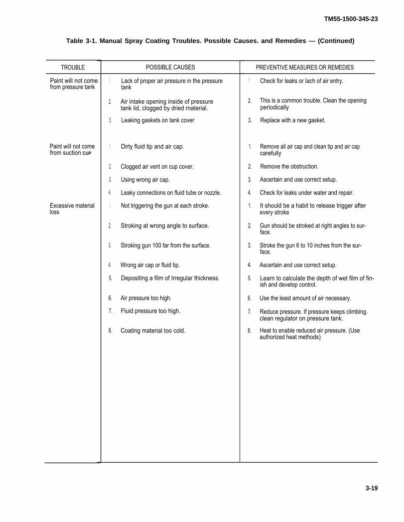
TM55-1500-345-23
Table 3-1. Manual Spray Coating Troubles. Possible Causes. and Remedies — (Continued)
TROUBLE
Paint will not comefrom pressure tank
Paint wiII not comefrom suction CUP
Excessive materialloss
POSSIBLE CAUSES
1.
2.
3.
1.
2.
3.
4.
1.
2.
3.
4.
5.
6.
7.
8.
Lack of proper air pressure in the pressuretank
Air intake opening inside of pressuretank lid, clogged by dried rnaterial.
Leaking gaskets on tank cover
Dirty fluid tip and air cap.
Clogged air vent on cup cover.
Using wrong air cap.
Leaky connections on fluid tube or nozzle.
Not triggering the gun at each stroke.
Stroking at wrong angle to surface.
Stroking gun 100 far from the surface.
Wrong air cap or fluid tip.
Depositing a film of Irregular thickness.
Air pressure too high.
Fluid pressure too high.
Coating material too cold.
PREVENTIVE MEASURES OR REMEDIES
1
2.
3.
1.
2.
3.
4.
1.
2.
3.
4.
5.
6.
7.
8.
Check for Ieaks or Iach of air entry.
This is a common trouble. Clean the openingperiodically
Replace with a new gasket.
Remove all air cap and clean tip and air capcarefully
Remove the obstruction.
Ascertain and use correct setup.
Check for leaks under water and repair.
It should be a habit to release trigger afterevery stroke
Gun should be stroked at right angles to sur-face.
Stroke the gun 6 to 10 inches from the sur-face.
Ascertain and use correct setup.
Learn to calculate the depth of wet film of fin-ish and develop control.
Use the least amount of air necessary.
Reduce pressure. If pressure keeps climbing.clean regulator on pressure tank.
Heat to enable reduced air pressure. (Useauthorized heat methods)
3-19


TM55-1500-345-23
Table 3-1. Manual Spray Coating Troubles. Possible Causes, and Remedies – (Continued)
TROUBLE
Failure of wet tapetest
Lifting
(figure 3-16)
Pitting or cupping
(figure 3-17)
Excessive spray fog
(figure 3-6)
Sandpaper finish
(figure 3-10)
3-22
POSSIBLE CAUSES
Insufficient drying time on wash primer and/orepoxy primer: Insufficiently cleaned surface:cleaning compound residue. etc. Oil seepagethroughout inspection doors and blind rivets(especially jet aircraft) entrapped oils and soil inepoxy shop primer: excessively aged primer:insufficient removal of shop primer and/or pre-ViOUS coatings: use of final finishes incorporat-ing wax ingredients: use of laundered ragsinstead of new mill ends: use of water-sensitiveprimer not conforming to specificationrequirements: seepage of water containingcleaning compound residues from between fray-ing surfaces.
1.
2.
1.
2.
3.
4.
Absorption of solvents by previous partiallydried film.
Second coats apt 10 lift if poorly preparedsurface.
Rust under surface.
Oil or grease on surface.
Moisture in lines.
Trapped solvents.
NOTE Do not mix materials and/or compo-
1.
2.
3.
4.
5.
1.
2.
3.
4.
nents of different manufacturers.
Too high air pressure.
Spraying past surface of the product.
Wrong air cap or fluid tip.
Gun stroked too far from the surface.
Material thinned too much.
Unsatisfactory wash primer or primer.
Excessive dirt contamination from paintingarea.
Insufficient scuff-sanding of wash primer orprimer.
Improperly cleaned paint lines.
PREVENTIVE MEASURES OR REMEDIES
Employ initial wipedown. using safety solventfollowed by thinner as an auxiliary cleaner. Rinsewith clear clean water when enzymatic cleaner i Sused: remove all shop primers to provide a cleansurface prior to any coating: primer shop coatelirnination preferred as 011 removal from shopprimer coats practically Impossible. employ solvent-dampened cloths in Iieu of dry cloths forremoval of oil contamination. Allow aircraft tostand for a sufficient time to permit drainage ofeffluent before final cleaning note the type of fail-ure. such as to bare metal or intercoat failure. andselect the applicable cause and remedy accord-ingly.
1.
2.
3.
1.
2.
3.
1.
2.
3.
4.
5.
1.
2.
3.
4.
Allow coal to dry before recoating. (Applica-ble only to single component paint.)
Begin with properly prepared surface
Use compatible coatings and thinners
Drain Iines periodically.
Use proper thinner proportions.
Strip and clean: or sand down and repaint
Use least amount of air pressure necessary
Release trigger when gun passes target.
Ascertain and use correct setup
Stroke the gun 6 to 10 inches from surface
Add the correct amount of solvent by meas-sure or test.
Laboratory analysis to verify acceptability ofthe material: check wash primer and primerapplication procedures.Provide cleaner painting areas.
Scuff-sand wash primer using No 320 andwet-or-dry abrasive. paper P-C-451.
Flush paint lines frequently with solvent.

TM55-1500-345-23
Table 3-1. Manual Spray Coating Troubles. Possible Causes. and Remedies — (Continued)
TROUBLE POSSIBLE CAUSES
5
1.
2
Dried overspray.
Settled. caked pigment or gelling paintblocking gun ttp.
Grit. dirt. paint skins. etc. blocking gun lip.fluid valve or strainer.
PREVENTIVE MEASURES OR REMEDIES
5. Sand the complete finish until smooth to thefingertips.
1. Remove obstruction. stir paint thoroughly.
2. Clean spray gun thoroughly and strain thecoating material. Always strain materialsbefore using.
3-23
Paint will not comefrom spray gun

TM55-1500-345-23
Figure 3-6. Excessive Spray Fog Figure 3-7. Paint Leaks From Spray Gun
Figure 3-8. Gun Sputters Constantly
3-24

Figure 3-9. Orange Peel
Figure 3-10. Sandpaper Finish Figure 3-11. Wrinkling
TM55-1500-345-23
3-25

TM55-1500-345-23
Figure 3-12. Crazing
Figure 3-13. Checking Figure 3-14. Blistering
3-26
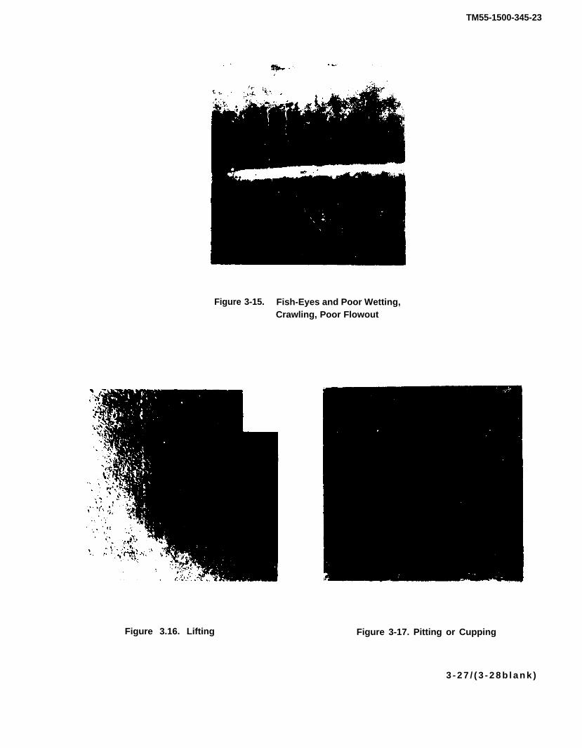
TM55-1500-345-23
Figure 3-15. Fish-Eyes and Poor Wetting,Crawling, Poor Flowout
Figure 3.16. Lifting Figure 3-17. Pitting or Cupping
3 - 2 7 / ( 3 - 2 8 b l a n k )

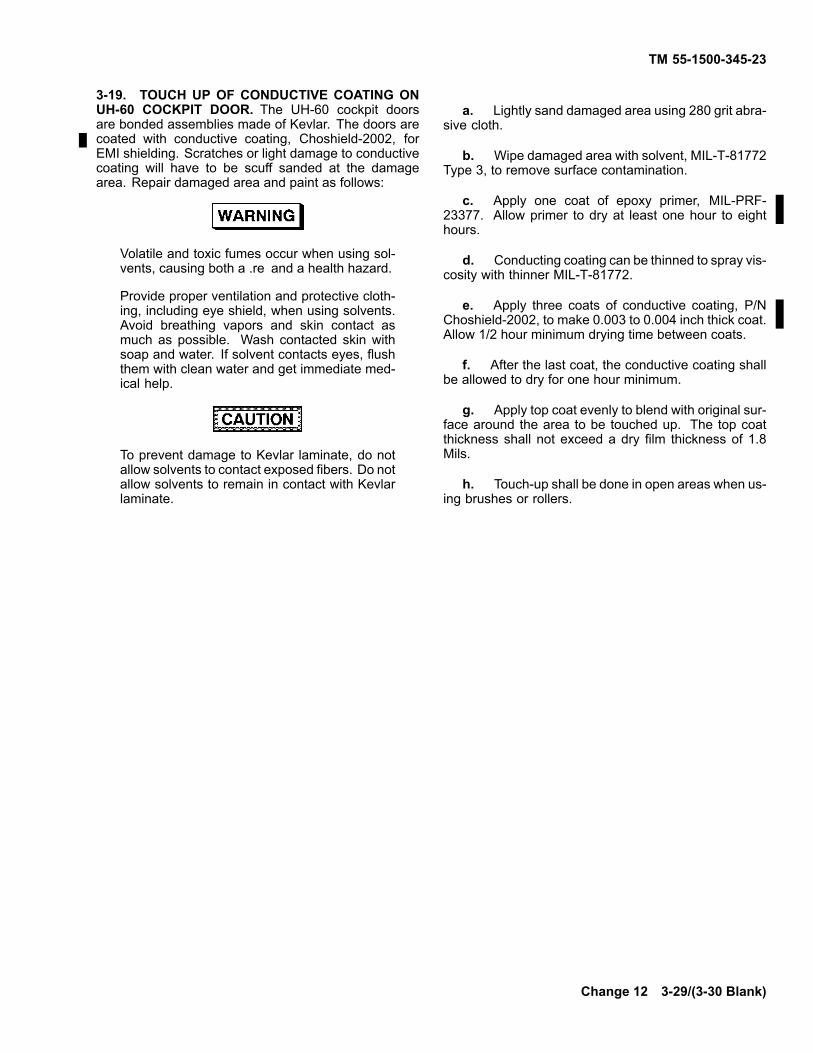
TM 55-1500-345-23
3-19. TOUCH UP OF CONDUCTIVE COATING ONUH-60 COCKPIT DOOR. The UH-60 cockpit doorsare bonded assemblies made of Kevlar. The doors arecoated with conductive coating, Choshield-2002, forEMI shielding. Scratches or light damage to conductivecoating will have to be scuff sanded at the damagearea. Repair damaged area and paint as follows:
Volatile and toxic fumes occur when using sol-vents, causing both a .re and a health hazard.
Provide proper ventilation and protective cloth-ing, including eye shield, when using solvents.Avoid breathing vapors and skin contact asmuch as possible. Wash contacted skin withsoap and water. If solvent contacts eyes, flushthem with clean water and get immediate med-ical help.
To prevent damage to Kevlar laminate, do notallow solvents to contact exposed fibers. Do notallow solvents to remain in contact with Kevlarlaminate.
a. Lightly sand damaged area using 280 grit abra-sive cloth.
b. Wipe damaged area with solvent, MIL-T-81772Type 3, to remove surface contamination.
c. Apply one coat of epoxy primer, MIL-PRF-23377. Allow primer to dry at least one hour to eighthours.
d. Conducting coating can be thinned to spray vis-cosity with thinner MIL-T-81772.
e. Apply three coats of conductive coating, P/NChoshield-2002, to make 0.003 to 0.004 inch thick coat.Allow 1/2 hour minimum drying time between coats.
f. After the last coat, the conductive coating shallbe allowed to dry for one hour minimum.
g. Apply top coat evenly to blend with original sur-face around the area to be touched up. The top coatthickness shall not exceed a dry film thickness of 1.8Mils.
h. Touch-up shall be done in open areas when us-ing brushes or rollers.
Change 12 3-29/(3-30 Blank)


TM 55-1500-345-23
CHAPTER 4TACTICAL PAINT SCHEME
SECTION I HELICOPTERS
4-1. GENERAL.
a. The coating system and painting scheme in thissection is the Army standard for tactical helicopters. Thefinish coat provides a lusterless, low visibility and lowreflectance surface in various military conditions.
b. This aircraft green topcoat conforms to MIL-DTL-64159 or MIL-DTL-53039. This topcoat is to beapplied over primer conforming to MIL-PRF-23377 orMIL-P-85582. Advantages of MIL-DTL-64159 or MIL-DTL-53039 top coating are its properties of resistance tochemical agents, increased abrasion and impact resis-tance, improved exposure and weathering performanceand superior longevity.
c. Aircraft green paint, MIL-DTL-64159 orMIL-DTL-53039, is rougher textured than most paints.This is intended, pursuant to achieving low reflectivityrequirements.
4-2. EXTERNAL AREAS NOT TO BE PAINTED.
a. Areas Not to be Painted (General). Do notprime or apply any paint to any of the following exteriorsurfaces:
(1) Light lenses, windows, and windshields.
(2) Wires and cables (electrical).
(3) Areas containing slippage or tolerancemarks unless the slippage or tolerance marks can beretained (1/2" masking tape may be used to covermarks).
(4) Rubber and cloth boots and dust covers.
(5) De-icing boots.
(6) Reinforced impregnated flexible ducting.
(7) Plastic or ceramic insulators for radio anten-nas.
(8) Rods that move in and out of hydraulic cylin-ders, on portions contacting a mating surface. Non-con-tact surfaces will be coated.
(9) Piston portion of landing gear struts andshimmy damper, where surfaces are mated.
(10) Interior and opening of pitot tube.
(11) Pitot static opening.
(12) Static ground receptacle.
(13) All bearings, races, and rod ends. Applymasking over, and 3/4 inch beyond, bearings, races,and rod ends. Masking will be snug and complete toprevent any spray from entering bearings, races, androd ends.
(14) All hydraulic fittings. Apply masking tocover fittings and about one inch of tubes.
(15) Ambient air thermometer probe.
(16) Required conspicuity markings.
(17) Previously unpainted Aircraft SurvivabilityEquipment.
Change 12 4-1
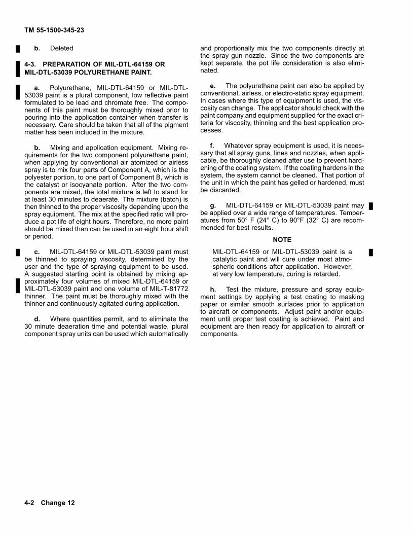
TM 55-1500-345-23
b. Deleted
4-3. PREPARATION OF MIL-DTL-64159 ORMIL-DTL-53039 POLYURETHANE PAINT.
a. Polyurethane, MIL-DTL-64159 or MIL-DTL-53039 paint is a plural component, low reflective paintformulated to be lead and chromate free. The compo-nents of this paint must be thoroughly mixed prior topouring into the application container when transfer isnecessary. Care should be taken that all of the pigmentmatter has been included in the mixture.
b. Mixing and application equipment. Mixing re-quirements for the two component polyurethane paint,when applying by conventional air atomized or airlessspray is to mix four parts of Component A, which is thepolyester portion, to one part of Component B, which isthe catalyst or isocyanate portion. After the two com-ponents are mixed, the total mixture is left to stand forat least 30 minutes to deaerate. The mixture (batch) isthen thinned to the proper viscosity depending upon thespray equipment. The mix at the specified ratio will pro-duce a pot life of eight hours. Therefore, no more paintshould be mixed than can be used in an eight hour shiftor period.
c. MIL-DTL-64159 or MIL-DTL-53039 paint mustbe thinned to spraying viscosity, determined by theuser and the type of spraying equipment to be used.A suggested starting point is obtained by mixing ap-proximately four volumes of mixed MIL-DTL-64159 orMIL-DTL-53039 paint and one volume of MIL-T-81772thinner. The paint must be thoroughly mixed with thethinner and continuously agitated during application.
d. Where quantities permit, and to eliminate the30 minute deaeration time and potential waste, pluralcomponent spray units can be used which automatically
and proportionally mix the two components directly atthe spray gun nozzle. Since the two components arekept separate, the pot life consideration is also elimi-nated.
e. The polyurethane paint can also be applied byconventional, airless, or electro-static spray equipment.In cases where this type of equipment is used, the vis-cosity can change. The applicator should check with thepaint company and equipment supplied for the exact cri-teria for viscosity, thinning and the best application pro-cesses.
f. Whatever spray equipment is used, it is neces-sary that all spray guns, lines and nozzles, when appli-cable, be thoroughly cleaned after use to prevent hard-ening of the coating system. If the coating hardens in thesystem, the system cannot be cleaned. That portion ofthe unit in which the paint has gelled or hardened, mustbe discarded.
g. MIL-DTL-64159 or MIL-DTL-53039 paint maybe applied over a wide range of temperatures. Temper-atures from 50° F (24° C) to 90°F (32° C) are recom-mended for best results.
NOTE
MIL-DTL-64159 or MIL-DTL-53039 paint is acatalytic paint and will cure under most atmo-spheric conditions after application. However,at very low temperature, curing is retarded.
h. Test the mixture, pressure and spray equip-ment settings by applying a test coating to maskingpaper or similar smooth surfaces prior to applicationto aircraft or components. Adjust paint and/or equip-ment until proper test coating is achieved. Paint andequipment are then ready for application to aircraft orcomponents.
4-2 Change 12

TM 55-1500-345-23
4-4. PROCEDURES FOR APPLICATION OFMIL-DTL-64159 OR MIL-DTL-53039 PAINT TO BAREMETAL SUBSTRATES. The total paint system for thepolyurethane coating as with all other paint systems,requires cleaning, a pretreatment coating, an anticorro-sive primer and the polyurethane topcoat. This appliesto painting of bare metal substrates.
a. Cleaning. The substrate should be thoroughlycleaned of all oil, grease and other contaminants by ap-propriate methods cited elsewhere herein or as speci-fied in TT-C-490.
b. Pretreatments. TT-C-490 finishing documentse.g., MIL-STD-193, MIL-STD-186, MIL-T-704, etc., pro-vide appropriate directions for surface preparation. Forsteel substrates, the pretreatments to use are zinc phos-phate or wash primer conforming to DOD-P-15328. Foraluminum, substrates, the pretreatment is alodine, MIL-C-5541.
c. Anticorrosive Primers. The anticorrosiveprimers to be used with the MIL-DTL-64159 orMIL-DTL-53039 paint system are the epoxy type.
The epoxy primer to use with steel substrates isMIL-P-52192 and for aluminum and magnesium sub-strates is MIL-PRF-23377, or MIL-P-85582.
d. Topcoat. MIL-DTL-64159 or MIL-DTL-53039coating is applied at 1.8 to 3.0 mils dry film thicknessin two coats. The first should be applied in one to fourhours of the application of the primer. The second coatmay be applied within a few minutes of the first coat oranytime thereafter. The total thickness of the topcoatshould not exceed 3.0 mils. There is no maximumtime between application of the first and second coats,ideally within two hours. No surface preparation, exceptfor cleaning, will be necessary as long as the surfacehas not become contaminated, e.g., with dirt or grease.MIL-DTL-64159 or MIL-DTL-53039 coating fully curesin 7 days.
e. MIL-DTL-64159 CARC topcoat is a alternate toCARC MIL-DTL-64159 or MIL-DTL-53039. MIL-DTL-64159 has been evaluated and approved for use by theAMRDEC Materials Branch, Structures and MaterialsDivision.
SECTION II FIXED WING AIRCRAFT
4-5. GENERAL. The tactical paint system is a three-coat system consisting of a chemical conversion coat-ing applied to bare metal, followed by an intermediateprimer coat, MIL-PRF-23377 or MIL-P-85582 and thenfinish-painted with a lusterless topcoat.
4-6. MATERIALS.
a. The chemical conversion coating will conformto MIL-C-5541 for aluminum and MIL-M-3171 for mag-nesium.
b. Intermediate primer will conform to MilitarySpecification MIL-PRF-23377 or MIL-P-85582
c. Aircraft Gray paint will conform to Military Spec-ification MIL-DTL-64159 or MIL-DTL-53039. For excep-tions to aircraft gray, see Chapter 5.
4-7. PROCEDURE.
a. Clean and prepare aircraft surfaces for paintingin accordance with Chapter 2.
b. Apply chemical conversion coating in accor-dance with manufacturer’s instructions.
c. Apply primer in accordance with the applicablespecification.
d. Apply finish coats in accordance with instruc-tions relating to application of MIL-DTL-64159 or MIL-DTL-53039 polyurethane coating.
Change 12 4-3
TM 55-1500-345-23
SECTION III MARKINGS
4-8. GENERAL. All markings, letterings, and nu-merals, including the identification lettering UNITEDSTATES ARMY, and radio call numbers, will be appliedwith Aircraft Black #37038 in compliance with instruc-
tions in Chapters 7, 8, 9 and 10. As an alternate, blacklusterless enamel may be used, overcoated with a clearpolyurethane in accordance with MIL-DTL-64159 orMIL-DTL-53039.
SECTION IV PROPELLER ASSEMBLIES AND BLADES
4-9. GENERAL. Details of the color scheme for pro-peller assemblies are in Chapter 6.
SECTION V AIRCRAFT COMPONENTS
4-10. GENERAL. Aircraft components that are in-stalled on an aircraft will be painted as follows:
a. New components shall be processed withMIL-PRF-23377 or MIL-P-85582 primer and paintedwith Interior Aircraft Gray #36231, per MIL-DTL-64159or MIL-DTL-53039 or Aircraft Black #37038, perMIL-DTL-64159 or MIL-DTL-53039 (as indicated inparagraph 1-5b) or MIL-C-22750 of the same color.
b. Recycled components shall be oversprayedwith a mist coat of MIL-PRF-23377 or MIL-P-85582unless condition of primer indicates a necessity for strip-
ping to bare metal, at which time the item will be com-pletely refinished. MIL-DTL-64159 or MIL-DTL-53039or MIL-C-27750 paint shall be applied as the top coat.
c. Zinc chromate shall not be used as a primer,unless it is subsequently oversprayed with MIL-PRF-23377 or MIL-P-85582.
d. Previously painted surfaces of Aircraft Surviv-ability Equipment will be painted. Caution shall be takento avoid any coating of radiating or receiving surfaces orwindows of this equipment.
SECTION VI APPLICATION TO PREVIOUSLY PAINTED SURFACES(ROTARY AND FIXED WING)
4-11. GENERAL. MIL-DTL-64159 or MIL-DTL-53039polyurethane paint must be applied over properly pre-pared subsurfaces. This paint shall not be applied overtopcoats other than MIL-DTL-64159 or MIL-DTL-53039painted equipment. Because of weight considerations,overcoating over MIL-DTL-64159 or MIL-DTL-53039paint shall be restricted to small areas.
4-12. TOUCH UP AND REPAIR WITH MIL-DTL-64159 OR MIL-DTL-53039. If there is not extensive
damage to the paint and touch up is for cosmetic pur-poses only or to cover up areas that are slightly marredor scratched, a supplemental polyurethane coatingmay be applied over the existing polyurethane finish.This must be done only on small areas and must beaccomplished by brush application. No special surfacepreparation is necessary except for cleaning. If a smallarea is broken or damaged down to the substrate mate-rial, that area must be sanded, reprimed and topcoated.See paragraphs 4-3 and 4-4.
4-4 Change 12

TM 55-1500-345-23
4-13. TOUCH UP AND REPAIR WITH MIL-DTL-64159 OR MIL-DTL-53039. Aircraft which are to-tally painted with MIL-DTL-64159 or MIL-DTL-53039paint must be touched up using MIL-DTL-64159 orMIL-DTL-53039. No special surface preparation is nec-essary except for cleaning. If a small area is broken ordamaged down to the substrate material, that area mustbe sanded, reprimed and topcoated. The epoxy primerto use with steel substrates is MIL-P-52192 and for alu-minum and magnesium substrates is MIL-PRF-23377or MIL-P-85582. See Chapter 3, Section II, "Primers"for details on primer use and application. Extensivetopcoat areas may be repaired by renewing the topcoatover existing primer if the primer is in good condition.
4-14. PREPARATION OF MIL-DTL-64159 ORMIL-DTL-53039.
a. Low reflective paint, MIL-DTL-64159 orMIL-DTL-53039, must be thoroughly mixed in the origi-nal container prior to pouring into the paint applicationcontainer.
NOTE
Paint application equipment must be cleanprior to first use of MIL-DTL-64159 orMIL-DTL-53039. Halts of 5 minutes or longerduration during application will require flushingof the paint lines and spray gun to remove driedparticles prior to restarting application.
b. Thoroughly mixed paint, MIL-DTL-64159 orMIL-DTL-53039, with appropriate thinner and retarder(as required) should be poured into the paint applicationcontainer only in quantities required for use that day.
NOTE
IMMEDIATELY after adding paint and thin-ner/retarder, agitation should be started andoperated for 1 to 3 hours prior to paint appli-cation. Paint agitation should be continuouslymaintained on liquids in the paint applicationcontainer.
c. MIL-DTL-64159 or MIL-DTL-53039 must bethinned to spraying viscosity. A suggested starting pointis obtained by mixing one volume of MIL-DTL-64159 orMIL-DTL-53039 with approximately one and one-halfvolumes of thinner composed of MIL-T-81772, Type III.The exact thinning ratio must be determined by the userand adjusted to the prevailing temperature and relativehumidity. An acceptable alternate thinner consists of2 parts by volume toulene (TT-T-548) and 1 part byvolume xylene (ASTM D846). The exact ratio of thinnerto paint must be determined by user and adjusted to theprevailing temperature and relative humidity.
d. MIL-DTL-64159 or MIL-DTL-53039 may be ap-plied over a wide temperature range of 40 °F (24°C) to90 °F (32 °C), and wide humidity range of 15 to 70%.High temperature and/or low humidity may result in dryspraying. High temperature and/or high humidity mayresult in blushing. To prevent these conditions and toprovide a satisfactory finish, MIL-E-7125, Ethylene Gly-col Monoethylether Acetate (cellosolve acetate or com-mercial equivalent such as Sherwin-Williams R7K206)may be required to first and second coat, and shouldbe added. Add up to 30% acrylic retarder (MIL-E-7125or commercial equivalent) as required, depending ontemperature and humidity. (The higher the temperatureand/or humidity, the more retarder required.)
e. Test the mixture, pressure and spray settingson masking paper or similar smooth surfaces prior toaircraft application to assure proper pigment disburse-ment. Large solids in test spray are indicative of dryspray and/or insufficient mixing. Add thinner, retarderand/or mix for a longer period of time, and retest as re-quired to attain smoothest possible surface finish.
4-15. PROCEDURES FOR APPLICATION OVERPROPERLY PREPARED SURFACES.
a. Apply two coats of MIL-DTL-64159 or MIL-DTL-53039 lacquer to a dry film thickness of about 1.5 mils.
Change 12 4-5

TM 55-1500-345-23
b. Apply first coat in continuous over-lappingstrokes. Going back over partially dried areas will causeexcessive surface roughness.
c. Allow first coat to air dry for approximately thirtyminutes. Remove all dust and dry overspray by lightlywiping with a lint free cloth and blowing with clean air.Apply second coat as in b above. After two coats, filmthickness should be approximately 1.5 mils.
d. MIL-DTL-64159 or MIL-DTL-53039 will dry suf-ficiently to be touched in approximately thirty minutes
and will dry sufficiently for flight in approximately fourhours. Markings may be reapplied at any time after thepaint is dried.
e. Do not reapply black paint to anti-glare areasbecause MIL-DTL-64159 or MIL-DTL-53039 is suffi-ciently dark to act as anti-glare. Application of heatresistant paint on the fuselage is not required.
f. When required, the low reflective paint andepoxy primer may be stripped by applying MIL-R-81294,remover, paint epoxy, and polyurethane systems.
4-6 Change 12

TM 55-1500-345-23
CHAPTER 5NON-TACTICAL PAINT SCHEMES
SECTION I GENERAL
5-1. SCOPE. This chapter is limited to non-tacticalpaint schemes for specific geographic locations andmissions other than tactical. Non-tactical paint schemeswere developed to provide high visibility in congestedareas, to enhance post-crash survival in hazardous ter-rain, or to identify a specific mission of an aircraft. Theinformation in this chapter is provided to help the majorArmy field commanders, with authorized deviations,to select the appropriate paint scheme commensuratewith the aircraft mission and location. In most cases,the standard tactical paint schemes in Chapter 4 arerequired.
5-2. AUTHORITY.
a. Major Army field commanders may apply fordeviation for the standard tactical paint scheme depictedin Chapter 4 by writing to AVSCOM, ATTN: AMSAV-MEA, who has the authority to grant the deviations. Re-search and development aircraft which are the responsi-bility of project or systems managers are exempted fromthis requirement.
b. Authority to use unique non-tactical paintschemes, markings, insignia, etc. that are differentfrom those described in this chapter, must be approvedby the major Army field commander and deviation
requests subsequently submitted to AVSCOM, ATTN:AMSAV-MEA, with complete justification (such assafety, mission requirement, cost reduction, etc.), andsketches or photographs describing the unique paintschemes. (See paragraph 1-4.)
5-3. WHEN TO PAINT NON-TACTICAL PAINTSCHEMES.
a. Aircraft in depot overhaul will be painted to anon-tactical paint scheme during overhaul if the majorArmy field commander, to whom the aircraft will be as-signed, requests a specific non-tactical paint scheme,or if it is otherwise known that the aircraft will be defi-nitely assigned to a mission or geographic location thatrequires a specific non-tactical paint scheme.
b. Newly-assigned aircraft that are known to havea limited length of assignment for a special non-tacticalmission or location should not be repainted to a non-tactical paint scheme.
c. Assigned aircraft having the standard tacticalpaint scheme of Chapter 4 may be repainted to a non-tactical scheme when the long-range mission or loca-tion of the aircraft is such as to require a non-tacticalscheme.
Change 2 5-1

TM 55-1500-345-23
5-4. PAINT IDENTIFICATION. Where non-tacti-cal paint schemes are authorized, the finish coatspecified in the non-tactical paint schemes may beobtained by use of the polyurethane MIL-DTL-64159or MIL-DTL-53039 or MIL-C-83286MIL-C-83286. SeeChapter 3 for appropriate primers.
5-5. SHADE NUMBERS. The shade numbers ofsome colors of non-tactical finish coats are as follows:
Gloss olive drab 14084
Gloss white 17875
Gloss black 17038
Gloss red 11136
Gloss international orange 12197
Fluorescent red-orange MIL-P-21600
5-6. FINISHING SYSTEM. The finishing or coatingsystems (sequence of paint starting from bare metal)for non-tactical paint systems are shown in Chapter 3.
SECTION II SPECIFIC
5-7. ROTOR BLADES AND PROPELLER ASSEM-BLIES. Paint schemes for rotor blades and propellerassemblies are covered in Chapter 6.
5-8. MARKINGS. Lettering, wording, insignia, etc.for non-tactical paint schemes shall be the same asfor standard tactical aircraft unless specifically statedotherwise in this technical manual.
NOTEDo not paint items currently unpainted, e.g., an-tenna masts, loops, antenna housing, radomes,exposed portions of operating mechanisms,transparent panels and anti-glare areas.
5-9. TRAINING AIRCRAFT.
a. TDA helicopters and fixed wing aircraft for train-ing purposes may require additional vivid color schemesand markings to provide high conspicuity due to inexpe-rienced student pilots flying in congested training areas.
b. The fuselage of the training aircraft will bethe standard tactical paint schemes of Chapter 4.In addition, areas of fluorescent red-orange paint(MIL-P-21600), or tape may be used when required and
authorized. See Chapters 9 and 10 for figures showingdetails of high conspicuity markings for aircraft used fortraining.
c. The use of high conspicuity tape in place of flu-orescent paint on flat or slightly curved aircraft surfacesoffers a better marking for a longer period of time due toits durability, resistance to fading and quick turn aroundto the tactical configuration when necessary. Tests in-dicate that the tape does not fade in one year of use,whereas fluorescent paint tends to fade in about fourmonths. Tape has limited application because it hidescracks and corrosion. Tape is to be applied only asshown in illustrations. To eliminate hidden corrosion,the tape shall not be applied over seams. Nonperfo-rated tape shall not be applied over rivet heads, but per-forated tape may be applied over rivet heads. Wherenecessary, the tape may be removed by the applicationof paint remover, MIL-R-81294.
d. TDA helicopters and fixed wing aircraft, usedfor training purposes, that are presently painted with in-ternational orange, in good condition, will not be refin-ished with fluorescent paint or tape. They will be main-tained with international orange until complete repaint-ing is required.
5-2 Change 12
TM 55-1500-345-23
5-10. AIRCRAFT IN CONGESTED AREAS. TDAhelicopters and fixed wing aircraft assigned to CONUSareas with high aircraft density may have the same highconspicuity paint schemes used for training aircraft,when approved as specified in paragraph 1-4.
5-11. AIRCRAFT FOR ARCTIC AND DESERT.
a. The paint scheme for tactical aircraft in arctic re-gions will be aircraft green unless otherwise designatedby the major Army field commander.
b. If directed by the major Army field commander,TDA helicopters and fixed wing aircraft destined for arc-tic, or desert regions which have not been designatedcombat areas, may be painted all white, desert sandor with high conspicuity paint schemes as described inChapters 9 and 10.
c. In general, there will be a highly conspicuousband around the front and the rear of the fuselage. Ver-tical fins, horizontal stabilizers, and tips of wings on fixedwing aircraft will also have highly conspicuous areas orbands. Details for specific aircraft are shown in Chap-ters 9 and 10.
d. Highly conspicuous schemes will facilitate lo-cating downed aircraft in the event of a forced or crashlanding on ice, snow, or in desert areas. Highly con-spicuous color schemes favor visibility in the arctic anddesert.
e. To reduce peeling of paint in extremely coldlocations (arctic, Alaska, etc.), the paint system shouldconsist of alodine treatment, MIL-PRF-23377 epoxyprimer, and appropriate urethane paints.
5-12. TEST SUPPORT AIRCRAFT. Aircraft utilizedby White Sands Missile Range and other desert test ordevelopment activities. Test Support Aircraft category,may be painted in the high conspicuity arctic or desertpaint scheme as described in Chapters 9 and 10.
5-13. MEDICAL RESEARCH AND GEODETIC AIR-CRAFT. During peacetime, aircraft for these servicesmay be painted with the high conspicuity arctic or desertpaint scheme as described in Chapters 9 and 10.
5-14. GREENLAND ICECAP AIRCRAFT. Aircraft op-erating in the area of the Greenland ice cap may bepainted entirely with international orange to ensure bet-ter inflight conspicuity and post-crash survivability.
5-15. MEDICAL SERVICE AIRCRAFT.
a. Army aircraft used as ambulance aircraft will bepainted with the tactical paint scheme of Chapter 4, andwill bear red cross insignia on a white field positioned onthe most suitable surface to be visible from either side,from the ground and from the air. (See Chapter 9).
b. The crosses will be in aircraft Red, No. 31336,MIL-DTL-64159 or MIL-DTL-53039 and the field in air-craft White, No. 37875, MIL-DTL-64159 or MIL-DTL-53039. The overall dimension of the cross depends onavailable space. The width and length of each protru-sion of the cross is one-third of the overall dimension,the white field will be square.
5-16. MILITARY ASSISTANCE PROGRAM AIR-CRAFT. All aircraft as signed to the Military AssistanceProgram (MAP) will conform to the tactical paint schemeof Chapter 4 except that they will possess no insignia,US Army markings, or aircraft serial numbers. MAPaircraft will be identified by three metal tags, citing serialnumber, affixed in three conspicuous within the aircraft.
5-17. STAFF TRANSPORT (VIP) AIRCRAFT.
a. Fixed wing aircraft, which have been desig-nated as staff transport aircraft are to be painted inaccordance with the paint schemes shown in Chapter10.
Change 12 5-3

TM 55-1500-345-23
b. Staff transport aircraft being prepared for acombat area may be converted to the tactical paintscheme of Chapter 4, at the request of the major Armyfield commander.
5-18. RESEARCH AND DEVELOPMENT AIR-CRAFT. The provisions of this manual will be used asrequired in determining the painting and markings to beapplied to research and development air vehicles. Thefollowing markings are considered mandatory for all
research and development air vehicles: Identificationlettering U.S. ARMY or ARMY, the national insignia, andthe vehicle serial and model numbers, and conspicuitypainting. Additional authorized markings will be appliedas required. All research and development air vehicleswill be conspicuously marked with the identificationlettering U.S. ARMY or ARMY on all sides when exteriorviews of the item are photographed or when the item ison public display.
5-4

TM 55-1500-345-23
CHAPTER 6FINISHES FOR SPECIFIC APPLICATIONS: GENERAL
SECTION I GENERAL
6-1. AIRCRAFT FINISHES. This chapter shallpresent requirements for finishes for specific applica-tions and applications not heretofore explicitly included.
a. All areas currently primed but unpaintedwill remain unpainted. Reprimed areas will useMIL-PRF-23377 or MIL-P-85582, e.g., under floor-boards, inside tailbooms, and behind acoustical mats.
b. Acoustical mats, light curtains, cargo covers,troop seats and like materials will not be painted.
6-2. SURFACE PREPARATION. Surfaces will be pre-pared and primed as specified in Chapter 2, prior to ap-plication of any top coat.
6-3. APPLICATION.
a. Gloss finishes will be used as specified herein.
b. Polyurethane finish, MIL-DTL-64159 orMIL-DTL-53039, aircraft green will be used for all Armyhelicopters, except as excluded per paragraph 1-10.
6-4. COLORS. Colors will conform to Federal Stan-dard 595 or the applicable military specification. MilitaryStandard 795 is a supplementary document to the stan-dard. Colors as Federal Standard 595 or Military Stan-dard 795 are designated by three digit numbers in theANA bulletins and by five digit numbers in the Federalstandard. Colors of paint compounds are identified bynumerical coding system.
a. The first digit identifies the gloss of the color.
(1) The numeral one indicates gloss.
(2) The numeral two indicates semigloss.
(3) The numeral three indicates lusterless.
b. The second digit identifies the selected colorclassification group.
(1) The numeral one indicates red.
(2) The numeral two indicates orange.
(3) The numeral three indicates yellow.
(4) The numeral four indicates green.
(5) The numeral five indicates blue.
(6) The numeral six indicates gray.
(7) The numeral seven indicates white or black.
c. The last three digits identify the approximate or-der of increasing diffuse reflection.
6-5. DECALS. Stencils will be used in lieu of decalswhere possible. If it is absolutely necessary to usedecals, they will be locally manufactured or obtained byalternative sources. Aircraft decals will not be stocked,stored or issued. Decals conforming to the require-ments of Military Specification MIL-P-38477, plasticfilm for marking aircraft, may be used lieu of paint ongloss painted aircraft for external and internal markingswithin the size limits specified herein or as otherwise,stated in paragraph 7-2. Large, one piece decals areunsatisfactory because of application difficulties. De-cals may be pressure sensitive, adhesive backed, andscored, but otherwise conforming to Military Specifica-tion MIL-P-38477. Pressure sensitive decals should beapplied in accordance with TM 1-1500-204-23 (Series).Pressure sensitive decals are not recommended for useon MIL-DTL-64159 or MIL-DTL-53039 painted aircraftexcept where stencil lettering size is impractical.
Change 12 6-1

TM 55-1500-345-23
SECTION II PROPELLER ASSEMBLIES AND ROTOR BLADES
6-6. GENERAL
a. Purpose. The finish used on propellers and ro-tor blades is applied to prevent corrosion or deteriorationof the underlying surfaces, to resist erosion from sandparticles, dust, for anti-glare purposes, to decrease vis-ibility of tactical aircraft used in some areas.
b. Paint Schemes and Shades. Paint schemesand shades for propeller assemblies and rotor bladesare shown in Chapters 8, 9, and 10.
c. Tactical vs Non-Tactical Optimum High Visibil-ity Schemes. Propeller assemblies and rotor bladesof tactical aircraft in tactical areas or in normal CONUSareas shall be painted according to the standard tacticalpaint schemes. The non-tactical optimum high visibilitypaint schemes for propeller assemblies and rotor bladesare permissible for TDA helicopters and fixed wing air-craft, as cited in paragraph 1-4. These schemes are toprovide high visibility of propellers and rotor blades un-der the following conditions:
(1) High density aircraft on the ground to reducethe risk of personnel walking into propellers or tail rotorblades.
(2) High density aircraft in the air to reduce mid-air collision by making the aircraft below more visible.
(3) Visibility of downed aircraft in arctic, jungleor desert areas.
(4) Visibility of downed VIP aircraft.
(5) Visibility of aircraft in a training environment.
d. Requirement. Before selecting the optimumhigh visibility paint scheme, commanders should giveconsideration to the requirements for funds, paintingand balancing equipment, and personnel to properlysupport the high visibility paint scheme.
e. Replacing Previous Schemes. Propellersand blades painted to previous non-tactical paint
schemes need not be repainted to the optimum highvisiblitiy scheme unless repainting is needed for otherreasons, such as excessive retouching or overhaul.TOE/MTOE helicopters which are painted with lowreflective tactical paint schemes using MIL-DTL-64159or MIL-DTL-53039, aircraft green, or aircraft grey, willnot have the striped high visibility paint scheme appliedto main or tail rotor blades. These aircraft will haveblades painted in accordance with MIL-DTL-64159 orMIL-DTL-53039, aircraft black #37038.
f. Precedence. Concerning touchup, over paint-ing, stripping, paint application and balancing; if thecontents of this TM disagree with instructions in theaircraft maintenance manual or in overhaul manuals,the latter manuals take precedence over this TM.
g. Touchup. When necessary, propellers andblades may be lightly touched up between overhaulperiods while installed on the aircraft. Care will beexercised to apply proportionate amounts of paint toeach blade to maintain proper balance. Where touchuppaint can be applied to all blades of an assembly inproportionate amounts, balance need not be accom-plished. This is not to be interpreted as an authorizationfor deletion of propeller or blade balance at overhaul, orat any other time, when balancing is normally required.
h. Overpainting for Optimum High Visibil-ity. The optimum high visibility non-tactical stripesin Chapters 8, 9 and 10 will not be added over theexisting tactical paint scheme. Similarly, the tacticalpaint scheme will not be added over the high visibilitypaint scheme. The blades should be stripped, paintedand rebalanced.
i. Stripping. Ensure all blade data and markingsare obtained prior to stripping paint from blades so thatthe same data and markings may be restenciled onapplicable blades subsequent to repainting. Propellerblades of fixed wing aircraft will not be stripped duringaircraft repainting unless necessary.
6-2 Change 12

TM 55-1500-345-23
When rotor blades are bonded construction, theoriginal finish should not be stripped becauseof possible harmful effects of paint stripperson bonding agents and adhesives. Personnelshould consult applicable maintenance manu-als for removal of old paint finishes from theseblades.
j. Paint Application. When applying primer or fin-ish coats, the blades and propellers must be in a hor-izontal position, and retained in that position until thepaint or primer has set. Primer and finish coats shouldbe sprayed on lightly and uniformly. Surfaces will beprepared and primed as specified in Chapter 2 unlessotherwise directed. Topcoat finishing materials shouldconform to those materials listed herein.
k. Balancing. After complete repainting or exten-sive touch-up, the propellers and blades must be rebal-anced in an intermediate maintenance or overhaul main-tenance facility.
Painting of main rotor, tail rotor, and propellerblades may create out-of-balance and unac-ceptable vibration conditions. Strict adherenceto instructions is required to reduce the prob-ability of creating these out-of-balance condi-tions. Care must be exercised to apply propor-tionate amounts of paint to each blade to main-tain proper balance.
NOTECH-54 main and tail rotor blades shall bepainted and balanced by the overhaul activityonly.
AH-64 main and tail rotor blades complete re-painting or extensive touch up should be ac-complished at an approved overhaul facility be-cause of balance requirements.
NOTE
Complete repainting of main and tail rotorblades on UH-60 and OH-58 aircraft is nor-mally accomplished during blade overhaul only.Main and tail rotor blades are individually bal-anced (spanwise and chordwise) to masterblades during overhaul after painting to insureinterchangeability between blades of the sameconfiguration. Painting of blades in the fieldmay cause subsequent interchangeability prob-lems.
NOTE
Minor touch up is only needed.
l. Paint Procedures for Drive Shaft and Couplings.Polish out all surface defects with Scotch Brite (7447-BTYPE II) (26066). Touch up polished area with paintepoxy primer base 1-1G-69 (06367) and epoxy primerhardener 1-H-75 (06367) or a suitable substitute. Firstapply a wash primer (MIL-C-8514 TYPE 1) NSN 8030-01-015-6104. Allow to air dry for 1 hour.
6-7. PROPELLERS.
a. For tactical aircraft.
(1) Follow Chapters 9 and 10 on a specific air-craft if it contains details about painting blades, spinneror hubs.
(2) If sufficient data does not exist in Chapters9 and 10, the standard tactical finish shall be AircraftBlack, MIL-DTL-64159 or MIL-DTL-53039, No. 37038,on both sides.
(3) The exterior surface of unplated hubs, foreand aft, will be painted with Aircraft Black, MIL-DTL-64159 or MIL-DTL-53039, No. 37038.
(4) Deleted
Change 12 6-3

TM 55-1500-345-23
b. For non-tactical aircraft.
(1) The blades may be painted with stripes perFigures 8-8, 8-9 and 8-11.
(2) On all propellers, paint the stripes on thefront side, and aircraft black on the back side. Platedhubs remain unpainted. Spinners to be painted asshown on figure 8-8.
6-8. MAIN ROTOR BLADES.
NOTE
Complete repainting of rotor blades should beaccomplished at an approved overhaul facilityor depot activity. The weight and balance ofblades is critical and complete repainting is notallowed by field units. Refer to applicable main-tenance manual for extent of painting blades.
a. For tactical aircraft. The upper and lower sur-face of main rotor blades shall be finished in AircraftBlack, MIL-DTL-64159 or MIL-DTL-53039, No. 37038.
b. For non-tactical aircraft.
(1) The under surface of the blades shall be fin-ished in aircraft black.
(2) The upper surface of the blades will bepainted with stripes per figure 8-8 and 8-13. Note thatthe outer two stripes are the same on all blades.
(3) For additional visibility in arctic areas, theouter 25% of the blades may be painted fluorescent redorange. The remaining portion of blades will be dividedinto 15% black and white segments as shown in the fig-ures.
(4) Deleted
(5) The rotor and hubs and control mechanismsshall be painted aircraft black, except for mating, loadbearing or dynamic surfaces.
c. Identifying dots of various colors will be in-stalled by the contractor on mounted blades for thepurpose of matching blade with identifying color on thehub. Blades ordered individually will not have identify-ing dots installed by the contractor, but will be added byfield personnel as required.
6-9. TAIL ROTOR BLADES.
NOTE
Complete repainting of rotor blades should beaccomplished at an approved overhaul facilityor depot activity. The weight and balance ofblades is critical and complete repainting is notallowed by field units. Refer to applicable main-tenance manual for extent of painting blades.
a. For tactical aircraft.
(1) Prime blade surfaces with epoxy typeMIL-PRF-23377 or MIL-P-85582. Apply primer in ac-cordance with Chapter 3.
(2) Both sides of the blades will be paintedAircraft Black, MIL-DTL-64159 or MIL-DTL-53039, No.37038.
(3) The rotor hubs and control mechanism shallbe painted aircraft black, except for mating, load bearingor dynamic surfaces.
b. For non-tactical aircraft.
(1) Prime blade surfaces with primer MIL-PRF-23377 or MIL-P-85582. Apply primer in accordance withChapter 3.
(2) Both sides of the blades may be painted withstripes per figure 8-8 and 8-13. Note that the outer twostripes are the same on all blades in figure 8-13.
(3) Application of stripes to tail rotor blades in-volves a 20% offset of non-concentric sections so as toprovide concentric rings during rotation. Careful atten-tion should be given to figures 8-8 and 8-13 when ap-plying this paint scheme.
(4) Deleted
(5) The rotor hubs and control mechanism shallbe painted aircraft black, except for mating, load bearingor dynamic surface.
(6) Deleted
6-4 Change 12
TM 55-1500-345-23
SECTION III AIRCRAFT EXTERIOR LANDING GEAR AND WHEELS
6-10. LANDING GEAR.
a. Helicopters. Helicopters skids and skid struc-tures will be painted in the same manner as the fuselage,with aircraft green, MIL-DTL-64159 or MIL-DTL-53039.When repainting helicopters, the skids will be removedfrom the aircraft, the skid wells and enclosures will beinspected, cleaned and repainted. The removed skidswill be inspected, cleaned or stripped, as appropriate,repainted and reinstalled on the aircraft.
b. Fixed Wing Aircraft. Landing gear of fixed wingaircraft will be processed in same paint as the fuselage.
Mating, dynamic or load bearing surfaces, e.g., oleo pis-tons will not be painted. Landing gear of non-tactical air-craft will be painted color 17925, MIL-C-83286.
6-11. WHEELS.
a. Wheel wells of tactical aircraft will be paintedAircraft White, No. 37875, per MIL-DTL-64159 or MIL-DTL-53039.
b. During repainting, wheel wells will be thor-oughly cleaned but not stripped.
SECTION IV WALKWAY COATINGS
6-12. WALKWAYS. Walkway coatings conformingto Military Specification MIL-W-5044 will be appliedon wing roots and heavy duty exterior traffic areasof all aircraft and overcoated with MIL-DTL-64159or MIL-DTL-53039, aircraft green or aircraft black.Walkway coating conforming to Military SpecificationMIL-W-5044, Type II may be applied directly over anyprimed, enamelled or acrylic nitro-cellulose lacquersurfaces of the aircraft exterior. These areas must beovercoated with MIL-DTL-64159 or MIL-DTL-53039aircraft green or aircraft black. The wing root walkwayswill be applied on both wing roots to a width of 18 inchesmeasured from the fuselage and will extend from just aftof the leading edge to just forward of the trailing edge.The exact width may vary from the 18-inch requirementfor specific aircraft. Safety walk, pressure sensitive ma-terial conforming to Military Specification MIL-D-17951,Type III, may be used as an option, but is not recom-mended. When such materials are used, they mustbe overcoated with MIL-DTL-64159 or MIL-DTL-53039
paints. Particular attention must be given the edges toassure good adhesion and sealing with MIL-DTL-64159or MIL-DTL-53039 paint.
NOTE
DELETED
a. Application Procedures for Walkway Coating,Military Speci.cation MIL-W-5044.
(1) Apply walkway coating in accordance withapplication instructions in Military Specification MIL-W-5050.
(2) After each coat, allow a minimum drying timeof 1/2 hour.
(3) After final coat, allow walkway coating to air-dry until set to touch before handling.
Change 12 6-5

TM 55-1500-345-23
Table 6-1. Typical Aircraft Interior Areas To Be Painted
ITEMAH-64 CH-47 OH-58 UH-60 *
Metal framework, doors and windows X X X X
Windshield frames X X X X
Metal structure, walls and ceilings X X X X
Glare shields, top and bottom andexposed operating accessories
X X X X
Instrument panels (metal structures) X X X X
Frame of pedestals or consoles X X X X
Seat frames, crewstations and cargocompartment
X X X X
Armor panels (omit rubber edging) X X
Metal portions of control systems X X X X
Crewstation handles, exit emergency X X X X
Foot control arms, rudder pedals andsupport brackets
X X X X
Exposed metal parts of air vents(except swivel joints)
X X
Exposed metal parts of logbook holder X X X X
Crewstation deck (including areasvisible from chin bubble, whereapplicable)
X X X X
Cyclic control sticks and adjustmentmechanisms
X X X X
1 Other fixed wing aircraft currently have commercial interior paint schemes notapplicable to this table.
6-6 Change 12

TM 55-1500-345-23
Table 6-1. Typical Aircraft Interior Areas To Be Painted — Continued
ITEMAH-64 CH-47 OH-58 UH-60 *
Collective control system, except lock X X X
Ash trays X X X X
Pedestal or console panel (sides) X X X X
Spare bulb holder (mask spare bulbs) X X X X
Overhead consoles (sides and edges) X X X
Radio transmit foot switches (somemasking required)
X X X X
Blanking plates on consoles orpedestals
X X X X
Crew and passenger stations X X X X
Canopy egress system and explosivecharge covering (exposed Teflon cordmust be masked with Scotch Cal tapeprior to painting)
X
Restraining bands and brackets for fireextinguishers
X X X X
Framework supporting transilluminatedpanels (lift panels to paint frame)
X X X X
Hand holds X X
Seats (adjusted to the most forward,aft and vertical positions to assure fullpaint coverage)
X X X X
Seat tracks, except sliding surfaces X X X
Collective pitch down lock (markingsin Orange-Yellow No. 33538, afterpainting)
X
Overhead console and switches(transilluminated). Touch-up, i.e., lightscratches and crazing
X X X X X
Change 12 6-7
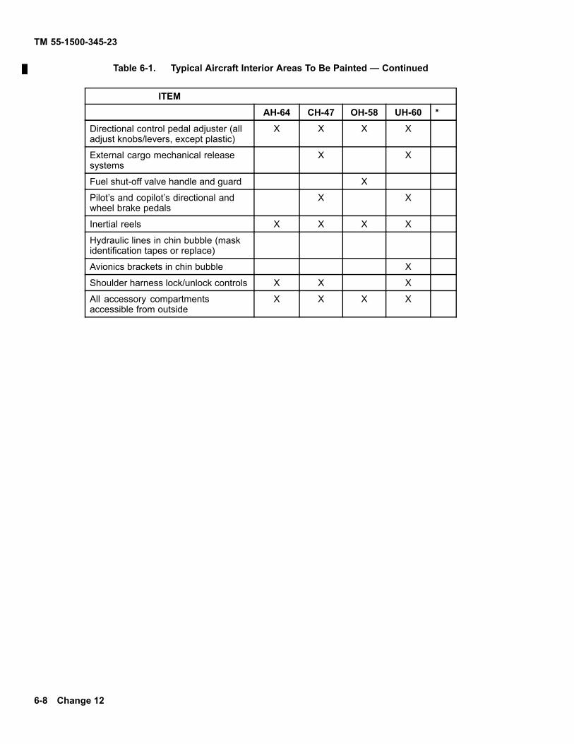
TM 55-1500-345-23
Table 6-1. Typical Aircraft Interior Areas To Be Painted — Continued
ITEMAH-64 CH-47 OH-58 UH-60 *
Directional control pedal adjuster (alladjust knobs/levers, except plastic)
X X X X
External cargo mechanical releasesystems
X X
Fuel shut-off valve handle and guard X
Pilot’s and copilot’s directional andwheel brake pedals
X X
Inertial reels X X X X
Hydraulic lines in chin bubble (maskidentification tapes or replace)
Avionics brackets in chin bubble X
Shoulder harness lock/unlock controls X X X
All accessory compartmentsaccessible from outside
X X X X
6-8 Change 12

TM 55-1500-345-23
Table 6-2. Typical Aircraft Interior Areas Not To Be Painted
ITEMAH-64 CH-47 OH-58 OV-1 UH-60 *
NOTE
In general, the goal is not to paint those items that .ex, issue instructions, orare transparent.
Windows and windshields (mask insideand out to avoid overpaint/oversprayand premature replacement)
X X X X X
Fire extinguishers X X X X
Oxygen cylinders X
First aid kits X X X X X
Restraint systems, including buckles(seat belts and shoulder harnessesshould be removed to avoid oversprayand premature replacement)
X X X X X
Seat cushions X X X X X
Plastic material in seats X X X X X
Instrument cases and glass (includingmagnetic compass and outside airtemperature gage)
X X X X X
Rod end bearings X X X
Electrical outlets X X X
Emergency handles X X X X
All placards, markings, and dataplates (yellow-orange stencils must berestenciled)
X X X X X
1Other fixed wing aircraft currently have commercial interior paint schemes not applicable tothis table.
Change 12 6-9

TM 55-1500-345-23
Table 6-2. Typical Aircraft Interior Areas Not To Be Painted — Continued
ITEMAH-64 CH-47 OH-58 OV-1 UH-60 *
Flexible ducts made of fabric or rubber X X X X X
Soundproofing blankets, fabriccovered panels
X X X X X
Key lock ignition switch (requiresmasking)
X X X X X
Pedestal panel (top) X
Deleted
Padded windshield wipers and/orrubber components
Governor control switch on copilot’scollective stick head
X X X X
Face of pilot’s collective stick head X X X X
Terminal boards X X X X X
Microphone control cords X X X X X
Cockpit utility lights X X X X X
External stores panel and jettisonhandle
X X X X
Compass switch X X X X X
Turret control panel X
6-10 Change 12
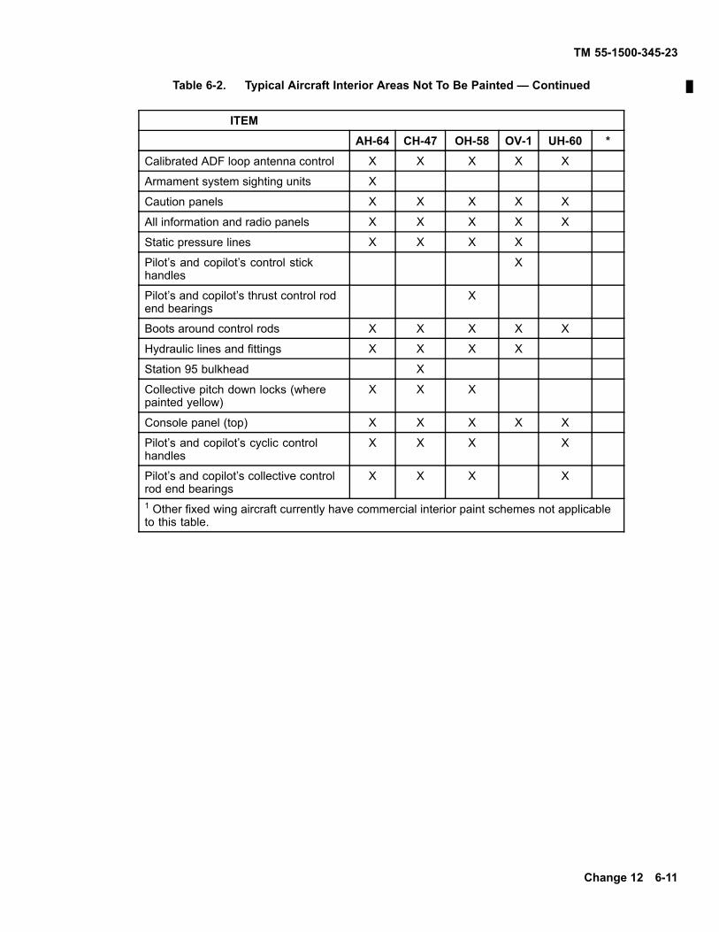
TM 55-1500-345-23
Table 6-2. Typical Aircraft Interior Areas Not To Be Painted — Continued
ITEMAH-64 CH-47 OH-58 OV-1 UH-60 *
Calibrated ADF loop antenna control X X X X X
Armament system sighting units X
Caution panels X X X X X
All information and radio panels X X X X X
Static pressure lines X X X X
Pilot’s and copilot’s control stickhandles
X
Pilot’s and copilot’s thrust control rodend bearings
X
Boots around control rods X X X X X
Hydraulic lines and fittings X X X X
Station 95 bulkhead X
Collective pitch down locks (wherepainted yellow)
X X X
Console panel (top) X X X X X
Pilot’s and copilot’s cyclic controlhandles
X X X X
Pilot’s and copilot’s collective controlrod end bearings
X X X X
1 Other fixed wing aircraft currently have commercial interior paint schemes not applicableto this table.
Change 12 6-11

TM 55-1500-345-23
NOTE
Full hardness is attained within maximum dryingtime of 24 hours.
(4) After walkway coating is completely dry,sand all edges to fair in with adjacent finished area.Walkways will not be polished or waxed.
(5) Apply MIL-DTL-64159 or MIL-DTL-53039paint over entire compound and over edges.
6-13. ANTIGLARE COATINGS. Helicopters paintedwith tactical paint schemes do not require antiglare paintforward of windshield.
6-14. BATTERY COMPARTMENTS.
a. Neutralization.
(1) Acid Electrolyte. Exercise care to preventacid from spreading to adjacent areas. Wash areasaffected by battery acid with 20 percent solution ofsodium bicarbonate, Federal Specification 0-S-576,in water. Neutralization is completed when bubblingceases. After neutralization, remove all traces ofsodium bicarbonate solution with generous quantitiesof water to prevent corrosion.
(2) Alkaline Electrolyte. Exercise caution toprevent acid from spreading to adjacent areas. Washareas affected by electrolyte with 3 percent solution ofboric acid in water. Neutralization is completed whenbubbling ceases. After neutralization, remove all tracesof boric acid solution with generous quantities of water.
b. Treatment After Neutralization. Treat affectedarea by swabbing with 5 percent solution of chromicacid, Federal Specification 0-C-303, or 5 percent ofpotassium bichromate, Federal Specification 0-P-559,followed by flushing with water and thorough drying.
c. Painting. After the above neutralization andtreatment, apply the following paint system:
(1) Apply two (2) coats of epoxy polyamideprimer, MIL-PRF-23377, Type I or Primer, MIL-P-85582.
(2) Apply (over these coats) one (1) coat ofprimer coating epoxy, MIL-P-52192.
NOTE
Coating (1), MIL-PRF-23377, is yellow. Whenwear, scratching, or other topcoat damage oc-curs, the yellow or gray primer undercoats willbe exposed indicating that repainting is neces-sary. This is essential to protect aluminum ormagnesium composite structures.
d. Touchup. Using organizations may touch upthe battery areas after proper neutralization.
(1) Acid Battery. One coat acid-proof varnishTT-V-51.
(2) Alkaline Battery. One coat MIL-C-83231,Type II coating.
6-12 Change 12

TM 55-1500-345-23
6-15. HIGH TEMPERATURE AREAS.
a. Below 400° F (204° C).
(1) Surfaces exposed to exhaust gases, corro-sive fluids, environmental elements, and areas known tobe subject to corrosive attacks for which ambient tem-peratures do not exceed 350 °F (177 °C), finish in ac-cordance with (2) through (3) below.
(2) Apply two coats of MIL-DTL-64159 or MIL-DTL-53039 paint, in appropriate color, over one coat ofepoxy primer, MIL-PRF-23377 or primer MIL-P-85582.
(3) Areas and components fabricated of mag-nesium or steel, other than corrosion resistant steel,that are exposed to temperatures exceeding 300°F(149°C), but not above 400°F (204°C), either on theground or in flight (other than momentarily), finish withMIL-DTL-64159 or MIL-DTL-53039 in appropriate color.Use primer, MIL-P-52192, where ferrous metals areinvolved.
b. Above 400° F (204° C).
(1) Coat aluminum alloy surfaces with heat re-sistant paint, military specification MIL-P-14105 Color
Shade No. 34087 for Olive Drab and TT-P-28, ColorShade No. 17178, for aluminum.
NOTE
These are modified silicone paints which re-quire heating to 450° F (232° C) for an hour af-ter application. However, when applied to tur-bine engine surfaces, the heat generated in nor-mal operation is considered adequate for cur-ing. Cured silicone paints will resist the attackof diester oils.
(2) On areas and components fabricated ofmagnesium or steel, other than corrosion resistantsteel, that are exposed to temperatures, from 400° F to500° F (204° C to 260° C), use silicone finish systemsapplied directly on the chemical surface-treated metal,omitting the wash prime and primer. Unless authorizedby the government procuring activity, the color will con-form to the color scheme for the aircraft. Above 500°F (260° C) use heat-resistant finishes as approved ineach instance by the government procuring activity.
(3) Deleted.
c. Deleted.
Change 12 6-13
TM 55-1500-345-23
6-16. RUBBER. Do not paint rubber components, ei-ther natural or synthetic.
6-17. ANTENNAS AND RADOMES.
a. If aircraft are painted without removing anten-nas and radomes, thoroughly mask the antennas andradomes.
b. Use the applicable TM 11 series manual forguidance on painting antennas.
c. On fixed wing aircraft, finish leading edges ofantennas and radomes exposed to the airstream withrain-erosion-resistant system conforming to MilitarySpecification MIL-C-83231 or MIL-C-83445 (See 6–33).
d. Radomes are not to be stripped or painted.
6-14 Change 8

TM 55-1500-345-23
SECTION V INTERIOR PAINTING
6-18. GENERAL.
a. General Information for PaintingCrewstations.
(1) All tactical rotary wing aircraft crewstationsshall be painted Aircraft Black, No. 37038, per MIL-DTL-64159 or MIL-DTL-53039. Tactical fixed wing aircraftshall be painted lusterless gray, per MIL-C-8779. Inte-rior marking stencils shall be Aircraft White, No. 37875,MIL-DTL-64159 or MIL-DTL-53039. When decals areused, they shall be white vinyl ink letters on a lusterlessblack background.
Paint residue can retard free movement of flightand power controls causing unsafe conditionsleading to a crash. Therefore, check all flightand power controls before flights followingpainting of aircraft interiors. Emergency han-dles should also be checked for freedom ofaction.
(2) See Table 6-1 for items to be painted. SeeTable 6-2 for items not to be painted.
(3) See Chapter 7 for general interior letteringand marking instructions.
(4) Uninhabited enclosures in the crewstationarea will also be painted Aircraft Black No. 37038 (e.g.,map holders, under console and circuit breaker panelsand equipment storage areas).
(5) Crewstations and passenger stations ofOH-58 aircraft will be painted Aircraft Black, No. 37038,per MIL-DTL-64159 or MIL-DTL-53039. Passengercompartments of fixed wing aircraft will be paintedlusterless gray or green per MIL-C-8779. Markings andstenciling applied in passenger stations of these aircraftwill be in Aircraft White, No. 37875, MIL-DTL-64159 orMIL-DTL-53039. Decals shall be white vinyl ink letterson a lusterless black background.
NOTE
Do not spray paint transilluminated consolepanels.
(6) Transilluminated console panels with craz-ing, scratches and gouges may be touched-up with lus-terless black lacquer. Touch-up may be accomplishedby using a small bristled brush, wetted with MIL-L-19538or MIL-DTL-64159 or MIL-DTL-53039, black #37038,lacquer.
b. Cargo/Troop Compartments.
(1) The aircraft cargo/troop compartments willbe painted either in polyurethane, MIL-DTL-64159 orMIL-DTL-53039, or epoxy paint, MIL-C-22750. Epoxypaint has characteristics equal to those of polyurethanein applications not continuously exposed to sunlight.
(2) Aircraft cargo/troop compartments willbe painted in Interior Aircraft Gray No. 36231,MIL-DTL-64159 or MIL-DTL-53039.
(3) Deleted
(4) Markings and stencils applied on the gray ofcargo/troop compartments will be in aircraft black, No.37038, per MIL-DTL-64159 or MIL-DTL-53039. Mark-ings applied on aircraft black will be in aircraft white, No.37875, MIL-DTL-64159 or MIL-DTL-53039.
(5) Uninhabited enclosures and/or bays ofcargo/troop compartments will be painted in the samemanner as the compartment, e.g., avionics compart-ments, hydraulic components, areas under acousticalmats.
c. External access and equipment bays and en-closures will be painted in aircraft black with markingsand stencils in Orange-Yellow, No. 33538, MIL-DTL-64159 or MIL-DTL-53039.
6-19. MIL-DTL-64159 OR MIL-DTL-53039,AIRCRAFT BLACK, NO. 37038, POLYURETHANEPAINT, CREWSTATION SURFACES.
a. The MIL-DTL-64159 or MIL-DTL-53039 top-coat is a plural component low reflective polyurethanepaint system, intended for use over epoxy polyamideprimer, MIL-PRF-23377 or MIL-P-85582.
Change 12 6-14.1
TM 55-1500-345-23
b. This coating system and paint scheme consti-tute the Army standard interior crewstation paint systemfor tactical aircraft. The system provides a non-specu-lar chemical resistant surface for aircraft crewstations.This paint system also enhances crewstation compati-
bility with electro-optical assisting devices and reducesthe exterior electro-optical signature.
c. Field crewstation touch-up procedures will in-clude brush and roller processes only.
6-14.2 Change 4

TM 55-1500-345-23
Spray equipment for touching up interior crew-station surfaces is not to be used, except byoverhaul, manufacturer or other facilities qual-ified to appropriate safety procedures.
d. Maximum effectiveness of lighting and chemi-cal/biological resistance is achieved when as much ofthe aircraft crewstation is coated as possible. It is partic-ularly important that surfaces which are touched or han-dled be properly maintained in this paint system.
6-20. EPOXY PAINT, MIL-C-22750, FOR INTERIORSURFACES OTHER THAN CREWSTATIONS.
a. This is a plural component paint which haschemical agent resistance equal to MIL-DTL-64159 orMIL-DTL-53039 paints. It is formulated for interior sur-faces which are not continuously exposed to sunlight.
b. MIL-C-22750 paint is applied in two coats. Ap-ply a mist coat and air dry for 15 minutes. The secondcoat should be applied until the total dry film thickness is1.7 to 2.3 mils. The total thickness of the topcoat shouldnot exceed 2.3 roils.
c. MIL-C-22750 may be used to refinish internallyinstalled components, see paragraph 5-1.
d. This paint may be used in cargo/troop compart-ments or uninhabited areas in lieu of MIL-DTL-64159 orMIL-DTL-53039. It should be painted in either gray orblack.
6-21. MIL-DTL-64159 OR MIL-DTL-53039,POLYURETHANE, INTERIOR AIRCRAFT GRAY,NO. 36231. This is a plural component polyurethanecoating paint, intended for use over epoxy polyamideprimer, MIL-PRF-23377, or MIL-P-85582.
6-22. PROCEDURES.
a. These procedures will be implemented bymaintenance personnel who have the proper trainingand equipment to apply epoxy primers and plural com-ponent polyurethane paints.
(1) It is essential that all painting and cleaningbe performed according to safety procedures describedin this TM. Occupational Safety and Health Administra-tion (OSHA) and National Institute of Safety and Health(NIOSH) requirements. Prior to operations, the paint-ing facility and processes must be approved by the localsafety office.
(2) It is imperative that crewstations be well ven-tilated during all painting operations, and proper respi-ratory equipment be used.
(3) Extreme care must be exercised to preventany paint or solvents from coming in contact with re-straint belts or the belts may be damaged and requirereplacement due to loss of tensile strength.
(4) There are four possible methods of applyingMIL-DTL-64159 or MIL-DTL-53039 paint to crewstationareas.
(a) Apply paint with spray equipment, afterappropriate masking, during manufacturing and produc-tion or aircraft overhaul only.
(b) Use of paint brushes or rollers at fieldlevel applications and maintenance.
(c) Dismantle assemblies, spray the parts inan appropriate facility and reassemble, as required.
(d) Combinations of the above.
(5) The choice of the proper method dependson the model of aircraft, the facilities and trained man-power available at the location to do the painting, thequantity of aircraft to be painted, condition of the exist-ing coatings, and the specific areas to be painted. Anymethod or combination of methods may be used withadherence to proper safety procedures.
b. Evaluate the existing coating to determine if theaircraft crewstation is in a condition to receive the MIL-DTL-64159 or MIL-DTL-53039 coating, or if the existingcoating must be stripped. If existing coatings are notacceptable, process in accordance with Chapter 2, Sur-face Preparation.
Change 12 6-15
TM 55-1500-345-23
c. Aircraft crewstations painted with MIL-DTL-64159 or MIL-DTL-53039 interior aircraft black arerough textured and are not acceptable surfaces.These surfaces must be stripped to the primer surfaceand reprocessed when a complete repainting is per-formed. (For touch up of areas previously painted withMIL-DTL-64159 or MIL-DTL-53039, see 4-13.) Whereprimer is worn through to the metal substrate, suchareas must be treated as metal substrate areas andprocessed in accordance with provisions herein forsuch areas.
d. Cabin areas of some UH-60A aircraft have atopcoat of TT-L-20, Gray No. 36231, that should bemaintained and touched up as required with the TT-L-20(camouflage lacquer) until these aircraft are convertedto an interior topcoat of MIL-DTL-64159 or MIL-DTL-53039.
e. Mask all cabin areas that may be damaged bypaint, paint vapors and cleaning solvents. See para-graph 6-26 for areas and items to be painted. This is par-ticularly important for acrylic surfaces such as canopiesand panels.
f. Primers required. Acceptable surfaces requireonly a flash coat of epoxy primer to insure maximum ad-hesion of MIL-DTL-64159 or MIL-DTL-53039 paint. Theflash primer coat may be eliminated if the area to bepainted is extremely small and the surfaces are accept-able according to paragraph 4-12 and are appropriatelycleaned prior to topcoating. Primers may be applied withbrushes or rollers.
(1) Apply a full primer coat on all areas wherethere is expected heavy abrasion wear (cabin decks,pedals, foot rests, etc.)
(2) It is necessary to reprocess all bare metalareas.
(3) Using the basic application procedure de-scribed in Chapter 3, apply MIL-PRF-23377 or MIL-P-
85582 Primers. Apply 0.6 to 0.9 mil to surfaces to beovercoated.
Allow the primer to dry one to two hours. Un-der some environmental conditions, shorter drying timesmay be allowable and preferred.
NOTE
As the drying time of epoxy primer increases be-yond two hours, the adhesion of the top coatmay decrease considerably. Care must be ex-ercised to observe the maximum primer dryingtime. When the time limit is exceeded, a mistcoat of primer must be applied to the surfaceprior to topcoating.
6-23. APPLICATION.
a. The amount of MIL-DTL-64159 or MIL-DTL-53039, Aircraft Black, No. 37038 paint will be mixedwhich will be used during the subsequent 6-8 hours.The thoroughly mixed components A and B will beallowed to set for a period of 30 minutes for aeration.This aeration period is not necessary if spray equipmentis to be used.
Spray equipment will be used only in crewsta-tions and similar confined areas when properventilation and protective equipment is used.
b. Subsequent to the aeration period the paint willbe stirred frequently to assure suspension of solid parti-cles and uniform surface application.
c. The mixture will be thinned in accordance withChapter 4. The exact thinning ratio and viscosity will bedetermined by the user and the application method.
6-24. APPLICATION WITH SPRAY EQUIPMENT.
a. Assure facility and equipment adequacy.
6-16 Change 12
TM 55-1500-345-23
b. Apply paint, after application of primer, whererequired. Allowing the appropriate drying period, applyfirst coat in continuous overlapping strokes. See Chap-ter 4 for additional instructions.
c. Allow first coat to set at least ten minutes be-fore application of second coat in continuous overlap-ping strokes to achieve the required dry film thicknessof 1.8 - 3 mils
NOTE
Continuous or frequent agitation of the mixturemust be maintained to assure suspension ofsolid matter and uniformity of topcoating.
d. The cured topcoating shall show no running,sagging, streaking or other surface inconsistencies.
e. Interior stencils and markings may be appliedany time subsequent to ten minutes after application offinal topcoat.
f. No heating or drying apparatus is required sincethis paint is catalytic and will cure under most ambientconditions. Full use cure will occur in 18-24 hours.
6-25. APPLICATION WITH BRUSH ORROLLERS. See Chapter 4.
6-26. TYPICAL AIRCRAFT INTERIOR AREAS TOBE PAINTED. Refer to Table 6-1.
6-27. TYPICAL AIRCRAFT INTERIOR AREAS NOTTO BE PAINTED. Refer to Table 6-2.
6-28. DECALS, PLACARDS, MARKINGS,LABELING IN COCKPIT AREA (WHEN USED).
a. General. Present decals, placards, markingsand labeling in the cockpit area of some helicopters maycause reflections which interfere with night flight. The
following actions are necessary to subdue the markingsand take full advantage of the low reflective black paintin the cockpit area.
b. Type Size. It is preferable to use a lettering fontin accordance with MIL-HDBK-759 and a width to heightratio of 1 to 8 to optimize readability under very low illu-mination levels.
c. Wire Bundles. For tactical aircraft, cover all ex-posed electric wire bundles with MIL-I-15126, black tapeto reduce reflections from light colored wires.
d. Remove the following from helicopter cockpitareas:
(1) Radio Magnetic Indicator Placard on CH-47.
(2) DC Electric Instrument Placard Label onTurn and Slip Indicators.
(3) Instrument Panel Checklist.
(4) Radio Call Designator/Aircraft IdentificationPlacard. Replace with new placard containing the wordsRADIO CALL in letters 3/16 inch high, and aircraft identi-fication numerals 5/16 inch high. Use lusterless AircraftWhite #37875 letters and numbers on an aircraft blackplacard.
(5) Deleted
(6) Compass Correction Card, RMI and Mag-netic. Place information in the front of the aircraft logbook where it can be referred to easily.
NOTE
It is permissible to locally manufacture a metalinsert painted lusterless black for installation inthe front of the compass card holder during nightflight.
Change 12 6-17

TM 55-1500-345-23
(7) Communication/Navigation Control BoxIdentification Labels on OH-58. These labels identifythe location of the control boxes in the console. Removethese labels from the side of the center console.
(8) Deleted
(9) Airframe Overhaul Facility or Quality ControlIdentification Decals. Remove these decals from thecrewstation area and reposition them to another loca-tion inside of the aircraft. The decals should be locatedso that they will not be easily rubbed or subjected to un-necessary weathering. They should be readable duringdaylight conditions.
(10) Deleted
(11) Deleted
(12) Crashworthy Fuel System Installed Decal.
(13) Operating Limits Decal on OH-58.
(14) Deleted
(15) GO-NO-GO Take-off Data Placard. PlaceTEAC maximum N1, RPM% and data entries in the frontof the aircraft log book where it can be referred to easily.
(16) Deleted
(17) Deleted
(18) Deleted
(19) Warning Decal for use of Engine Conditionlevers Below 17 °C on CH-47C.
(20) Radio Transmitter Select IdentificationPlacard.
e. Redundant labels of Instrument on UH-1, andOH-58. Several instruments on the OH-58 have theirfunction displayed on the instrument and also on a plac-ard or label on the panel adjacent to the particular instru-ment. Remove all duplicate labeling from the instrumentpanel. Judgement must be exercised before removingthese labels. For example, there are two temperaturedisplays having the same dial face, but one is used forthe engine and the other is used for the transmission;both panel labels for these two instruments shall remain.The gas producer display, on the other hand, has dupli-cate labeling on the instrument and on the instrumentpanel; the panel label should be removed.
f. VNE Computer on CH-47. Do not make anychange to this computer.
g. Marking General. Any placards, decals, mark-ings, or labeling not discussed above shall be retainedbut modified if necessary to have lusterless AircraftWhite #37875 lettering/marking on a low reflective blackbackground.
h. Placard Material. Placards may be made ofL-P-387A plastic sheet, laminated, type NDP, 1/6 inchthick, opaque, dull black face with white core; or equiv-alent.
i. Adhesives. Before applying decals, placards,tape or labels, lightly sand the paint in the area ofapplication. Adhesive EC847 may be used for placards.
j. Touch-up. If the instrument panel was alreadypainted with black before receipt of this TM, removeand/or replace markings, placards, labels, etc., accord-ing to the instructions in para 4-5. Touch up the panel.
k. Removal of Decals, Labels, etc. To removedecals, labels, etc. follow TM 1-1500-204-23 (Series),or use a razor blade.
6-18 Change 12

TM 55-1500-345-23
6-29. EMERGENCY EXIT MARKINGS.
a. General.
(1) All lettering and markings shall be inOrange-Yellow, No. 33538, MIL-DTL-64159 orMIL-DTL-53039.
(2) Doors and door frames shall be painted Air-craft Black, No. 37038, MIL-DTL-64159 or MIL-DTL-53039, in accordance with para 6-22a.
(3) The information in the following paragraphssupplements information in Chapter 7, Section X and inChapter 8 concerning interior markings for the cockpitarea.
(4) Striping on the door shall consist ofOrange-Yellow, No. 33538, MIL-DTL-64159 orMIL-DTL-53039, markings 1/2 inch by 1 inch (positionedlengthwise) spaced one foot apart around the door.
b. Deleted
c. Deleted
d. Emergency Exit Markings on OH-58.
(1) Apply the words EMERGENCY RELEASEon the diagonal forward portion of the door frames asclose to the door jettison handles as possible.
(2) Apply the word PULL, with an arrow to indi-cate the hand motion required, adjacent and just belowthe door jettison handles.
(3) The door jettison handles shall be paintedorange-yellow and black 1/8 inch wide alternate stripes.
(4) Place the words EMERGENCY EXIT on thecenter of the side panel of the door.
(5) Apply the words OPEN-CLOSED.
e. Emergency Exit Markings on CH-47. Applythe words EMERGENCY EXIT/TURN HANDLE mark-ing adjacent to the door jettison handle.
Change 12 6-19
TM 55-1500-345-23
SECTION VI PROTECTIVE COATINGS
6-30. COATINGS FOR FIBER LAMINATEMATERIALS.
a. Sandwich-type laminate parts in aircraft arecoated for several reasons with the type of coatingbeing chosen for the specific application of the part.Plastic parts such as radomes are normally coatedprimarily for rain erosion resistance. Paints shall notbe applied to radomes or antennas unless specificallydirected in 6-17.
b. In repairing sandwich-type laminate parts, thefinal step is to refinish the part with a finish identical tothe original finish. (Refer to drawings and applicablespecifications of the parts).
NOTE
There will be no protective coating sprayedupon radomes for prevention of scratching ormarring during transport” tion. As previouslyemphasized, items constructed of fiberglassmaterial require special handling at all times toprevent damage. Addition of protective coat-ings for prevention of such damage would notprevent major damage and would tend to reem-phasize special handling precautions. Surfacewill be protected by covering with paper orsimilar material.
6-31. PROTECTIVE COATINGS FOR RAIN ERO-SION. Fiberglass laminated surface located on thefrontal areas of aircraft are subjected to considerableerosive action when flying through rain. These ar-eas must be protected to prevent severe damage tothe fiberglass surface. Rain erosion coating systemsconforming to Military Specification MIL-C-83231 andMIL-C-83445 applied to affected surfaces will provideprotection from the effects of rain erosion. These ma-terials will protect the fiberglass surface indefinitely,providing the coating is replaced or repaired wheninspection indicates such work is necessary. Ther-mally reflective elastomeric coating system, Military
Specification MIL-C-83445 is a dual purpose coatingto be used as a thermally reflective coating on exteriorlaminated plastic parts where protection from rain ero-sion is required. For economic reasons, the thermallyreflective coating will be used only where both thermaland erosion protection is an established requirement.
a. Rain erosion resistant coating systems, MilitarySpecification MIL-C-83231.
(1) Class A, Type I, is a rain erosion resistantcoating furnished in complete kit form.
(2) Class A, Type II, is a rain erosion resistantcoating with antistatic surface treatment to minimize ra-dio noise from precipitation charging of the coated sur-face furnished in complete kit form.
b. Thermally reflective coating system, MilitarySpecification MIL-C-83445, are classified as follows:
(1) Class I rain erosion resistant thermal coatingfurnished in kit form complete with primer, erosion resis-tant (electrically nonconductive) component, and dilut-ing solvent.
(2) The coatings are intended for exterior lam-inated plastic parts of aircraft for protection from rainerosion and thermal energy while the aircraft is in flight.These coatings cannot be used on radomes and otherplastic parts that have a requirement for protectionagainst static electrical charges because they are notelectrically conductive.
c. Provide rain erosion protection on wing tip as-semblies and other aircraft parts constructed of fiberlaminates which present an in-flight angle of impact of 15degrees or more. Do not provide rain erosion protectionon leading edges and areas of radomes and antennahousings unless specifically directed in 6-17. Head-onimpact of a flat surface is defined as a 90-degree
6-20

TM 55-1500-345-23
angle of impact. Angular impact determinations mustbe based on the position of the part when in a normalinflight attitude.
NOTE
Only the amount of material to be used withinthe following 8 hours should be accelerated atone time. Material that has been mixed and al-lowed to stand beyond this period of time shouldbe discarded. Do not attempt to thin any coat-ing material which has gelled beyond brushableuse. Keep containers tightly covered when notin use.
6-32. PREPARATION OF SURFACE.
Aliphatic Naphtha, TT-N-95Aliphatic naphtha is flammable and toxic toeyes, skin, and respiratory tract. Wear pro-tective gloves and goggles/face shield. Avoidrepeated or prolonged contact. Use only in wellventilated areas (or use approved respirator asdetermined by local safety/industrial hygienepersonnel). Keep away from open flames,sparks or other sources of ignition.
AcetoneAcetone is extremely flammable and toxic toeyes, skin, and respiratory tract. Wear pro-tective gloves and goggles/face shield. Avoidrepeated or prolonged contact. Use only in wellventilated areas (or use approved respirator asdetermined by local safety/industrial hygienepersonnel). Keep away from open flames,sparks or other sources of ignition.
Failure to observe these precautions con result in seri-ous injury or systemic poisoning of personnel.
a. Repair surfaces with pits, scars, scratches, orother minor defects in accordance with TM 55-1500-204-25/1. It has been found that coatings are more sat-isfactory if the surface to receive the coating is smoothbut not glossy.
b. Remove surface gloss with a fine grade ofemery or sandpaper, No 240 grit, after sanding lightlywith a coarser grade of abrasive so as to finely and uni-formly scratch the surface. Remove sanding dust with aclean, lint-free cloth dampened with aliphatic naphtha,TT-N-95, followed by an acetone, ASTM-D329, wipeused with the coating. Assure that surface is completelydry before coating application.
Since materials used in coating removal and ap-plication procedures are flammable and toxic insufficient concentration, standard precautionssuch as fire prevention and adequate ventilationshall be exercised.
6-33. APPLICATION OF PRIMER AND COAT-ING. Plastic parts to be coated with erosion resistantcoatings should be processed in a sheltered area freefrom dust, and protected from weather conditions.Best results are obtained if the coatings are applied atrelative humidities below 60 percent.
a. Application of Coating System, Military Specifi-cation MIL-C-83231.
(1) Mixing. Components of classes A and B,types I and II coatings shall be individually mixed inaccordance with the manufacturer’s instructions. Theresulting individual mixtures shall be smooth, homoge-neous materials free from lumps, gelling, seeding, sep-aration or other objectionable characteristics.
(2) Pot Life. Classes A and B coatings shallhave a minimum pot life of 4 hours at standard condi-tions. At the end of the 4 hour period, the coatings shallshow no signs of lumping, seeding, separation or an in-crease in viscosity of more than 20 percent from the ini-tial viscosity.
(3) The class A and B coatings shall be appliedin accordance with the manufacturer’s instructions to atotal dry film thickness of 12 to 14 mils. The total ap-plication time, including priming and intervals betweencoatings shall not exceed 8 hours. The tack free dryingtime for class A coatings shall not exceed 4 hours afterapplication of the final coat. The tack free drying timefor class B coatings shall not exceed 10 hours after ap-plication of the final coat.
(4) The rate-of-cure of the class A and B coat-ings shall have a maximum set-to-touch or recoat timeof one hour. For class B materials, the manufacturershall furnish instructions for catalyzing or acceleratingthe polyurethane prepolymer materials for a tempera-ture range from 10°C to 35°C (65°F to 95°F) and a rela-tive humidity range from 40 percent to 75 percent.
(5) Class A coatings shall be fully cured within5 days and shall be free of pinholes, cracks,
Change 12 6-21

TM 55-1500-345-23
bubbles or other .lm irregularities. Class B coatingsshall be fully cured within 10 days and shall be free ofpinholes, cracks, bubbles, or other film irregularities.
b. Application of Coating System, Military Specifi-cation MIL-C-83445.
(1) Mixing. Components of class 1 and 2 coat-ings shall be individually mixed in accordance with themanufacturer’s instructions. The resulting individualmixtures shall be smooth, homogeneous materialsfree from lumps, gelling, seeding, separation or otherobjectionable characteristics.
(2) Pot Life. Class 1 and 2 base coating andtopcoating solutions shall have a minimum pot life of 4hours after catalyzation. At the end of the 4 hour period,the coatings shall show no signs of lumping, seeding,separation or an increase in viscosity of more than 20percent from the initial viscosity when tested in accor-dance with 4.7.9 and Table 6-1.
(3) The coatings shall be applied in accordancewith the manufacturer’s instructions to a total dry filmthickness of 12 to 14 mils. The total application time,including intervals between coatings shall not exceed 8hours and the tack free drying time shall not exceed 10hours after final application of the coatings.
(4) The rate-of-cure of the coatings shall have amaximum set-to-touch or recoat time of one hour. Themanufacturer shall furnish instructions for catalyzing oraccelerating the polyurethane base materials for a tem-perature range from 65° to 95°F (18° to 35°C) and a rel-ative humidity range from 40 to 75 percent.
(5) Class 1 and 2 coatings shall be fully curedwithin 5 days and shall be free of pinholes, cracks, bub-bles or other film irregularities.
6-34. PATCHING OR RETOUCHING DAMAGEDCOATINGS.
AcetoneAcetone is extremely flammable and toxic toeyes, skin, and respiratory tract. Wear pro-tective gloves and goggles/face shield. Avoidrepeated or prolonged contact. Use only in wellventilated areas (or use approved respirator asdetermined by local safety/industrial hygienepersonnel). Keep away from open flames,sparks or other sources of ignition.
Aliphatic Naphtha, TT-N-95Aliphatic naphtha is flammable and toxic toeyes, skin, and respiratory tract. Wear pro-tective gloves and goggles/face shield. Avoidrepeated or prolonged contact. Use only in wellventilated areas (or use approved respirator asdetermined by local safety/industrial hygienepersonnel). Keep away from open flames,sparks or other sources of ignition.
Failure to observe these precautions can result in seri-ous injury or systemic poisoning of personnel.
Sand damaged surface to a feather edge. Extendsanded surface beyond damaged area approximately1 inch. Clean sanded surface with a clean, lint-freecloth dampened with aliphatic naphtha followed byan acetone wipe, Federal Secifications TT-N-95 andASTM D329. Immediately wipe with a second dry,clean, lint-free cloth to remove residue and allow todry thoroughly. Apply primer and coating(s) as pre-viously directed herein. Exercise extreme caution toprevent uneven and excessive buildup of coating whenmaking repairs to radome coatings. Excessive coatingthickness will reduce radome electrical transmissionefficiency and in the case of doppler and fire controlradomes, could result in beam deflection errors beyondtolerable limits.
6-35. REMOVAL OF COATINGS.
METHYL ETHYL KETONEKeep away from heat and open flame.Keep container closed.Use with adequate ventilation.Avoid prolonged breathing of vapors.Avoid prolonged or repeated contact with skin.
Failure to observe these precautions can result in seri-ous injury or systemic poisoning of personnel.
a. Prior to application of neoprene, inspectradomes for damages that penetrate face plies. To pre-vent the solvent from entering the radome core, coverdamages that penetrate face plies with tape, FederalSpecification PPP-T-60. Extend tape approximately 3inches beyond edges of damaged area. Do not attemptto remove coating under the tape. This coating will beremoved either with face ply when damaged area isrepaired, or by hand sanding.
b. Removal of erosion resistant coatings shall beaccomplished by one of the following methods:
6-22 Change 12

TM55-1 500-345-23
Handling and use of coating removalsolvents requires normal precautionscommensurate with their toxicity andflash.point characteristics. Thesesolvents tend to dry out the skin andmay cause skin disorders to someindividuals. Therefore, protection tohands shall be provided by appropriategloves or gauntlets.
(1) Cover coating with a felt pad or ragsand saturate with 50/50 mixture of toluene, Fed-eral Specification TT-T548, and methylethyketone,Federal Specification TT-M-261. Maintain cover-ing in a saturated condition until coating has loos-ened to the extent that it can be peeled off orscraped off with a phenolic or plastic handscraper. If a hand scraper is used, care must beexercised to prevent scratching the surface of theradome. Remove residue with a cloth dampenesswith toluene or methylethylketone.
Change 1 6-22.1 /(6-22.2 blank)


TM55-1500-345-23
Electrically ground table and pump toguard against static discharge.
(2) The appl icat ion of a cont inuousstream of solvent mixture is an alternate method
of removing coatings. Suggested equipment con-sists of a metal table of suitable size with a metalgrid top and provisions for draining the solventthrough a filter to a low pressure explosion-prooffluid pump. Position radome or part on table withpipes or rods between radome and grid top. Toprevent possible delamination of solid laminateedge bands, do not place part directly on, or dragit across, the metal grid table top. Cover coatedarea as previously described and apply a streamof solvent mixture until coating loosens. Removecoating as previously described.
N O T E
Solvent mixture must not contain morethan 50 percent methyethylketone,Federal Specification TT-M-251. Meth-yethylketone in excess of 50 percentwill be harmful to materials. Toluene,Federal Specification TT-T-548, used byitself will satisfactorily remove neo-prene coating, however, the reactiontime is longer than that for methyle-thylketone-toluene mixture.
6 - 3 6 . R E M O V A L O F P A I N T F R O MR A D O M E S .
Do not remove paint from radomes.
When stripping paint adjacent toinstalled radomes, it is mandatory thatpaint strippers and solvents do not con-tact the fiberglass, and are notpermitted to flow into edge band areasof radomes. (Refer to Chapter 6.)
6 - 3 7 . P R O T E C T I V E C O A T I N G F O R T H EP O L Y C A R B O N A T E A N D P V C / A C R Y L I CPOLYMER COVERING ON THE CANOPYEGRESS SYSTEM.
a. Clean the canopy egress system coveringwith alcohol, Federal Specification 0-E-760.
b. Sand surface with 400 grit sandpaper.
c. Clean the covering again with alcohol,Federal Specification 0-E-760.
d. Apply Lexcote G-3483 per manufacturer’sinstructions.
e. Infrared heat lamp may be used to aid in thecur ing o f the Lexco te .
6-23/(6-24 Blank)


TM 55-1500-345-23
CHAPTER 7LETTERING AND MARKING
SECTION I MARKINGS
7-1. GENERAL.
a. The color for the majority of markings and let-tering will be aircraft black, shade number 37038, MIL-DTL-64159 or MIL-DTL-53039, on aircraft green or air-craft grey background. The crew areas will normallybe marked in orange-yellow, number 33538, MIL-DTL-64159 or MIL-DTL-53039 on aircraft black background.See details in Chapters 9 and 10.
b. Unless otherwise speci.ed, use 1/2-inch highArabic numerals and capital letters for markings. If let-tering shown in Chapters 9 and 10 cannot be madeon standard Army stencil cutting machine due to oddsize letters, go to the nearest standard size. For exam-ple (shown in figure 8-2), 5/8 in., replace with 1/2 inch.Markings and lettering may be reduced in size to suitcombat operation.
c. Center identification lettering UNITED STATESARMY as nearly as possible on each side of fuselage.
Use 6-inch vertical block letters. Letter dimensions, po-sitions, and locations for each aircraft will be in accor-dance with instructions in Chapter 8. When identificationlettering UNITED STATES ARMY does not fit on allottedspace, use U.S. ARMY or ARMY.
Cutting of fuel, oil, hydraulic, or oxygen lines, orelectrical wiring under crash conditions may re-sult in a fire or explosion or increase the sever-ity of an existing fire. Such possibilities will betaken into consideration when emergency es-cape areas are being chosen for identificationmarkings.
d. Outline corners of emergency exits and rescueexit areas with right-angle corner bands 1 inch wide and3 inches long at each leg. Paint corner marks with black,shade number 37038, Military Specification MIL-DTL-64159 or MIL-DTL-53039.
SECTION II INSIGNIA: GENERAL
7-2. LETTERING AND MARKING MATERIALS.
a. Apply insignia with approved paint as applica-ble and compatible with the existing finishes.
b. Use decals conforming to paragraph 6-5, in lieuof paint, if approved by AMCOM, ATTN: AMSAM-DSA-AMSS-FW, Redstone Arsenal, AL 35898–5000.
7-3. GENERAL.
a. The National Star Insignia will not be applied totactical aircraft. The National Star Insignia, of the designshown in figure 8-1, will be placed on other Army aircraftwhere required as part of an authorized paint scheme.
b. The insignia will portray an insignia white,five-pointed star located within an insignia-blue circum-scribed circle. This is referred to as the
Change 12 7-1

TM 55-1500-345-23
basic blue circle. An insignia-white rectangle will be lo-cated on each side of the star. The top edge of the rect-angles will form a straight line with the upper edges ofthe horizontal opposed star points. An insignia-red hor-izontal stripe will be centered in each end of the rectan-gle. The basic blue circle will outline the entire insignia.
c. The dimensions of the insignia will be deter-mined by the diameter of the basic blue circle, which isstandardized in multiples of 5 inches.
7-4. COLORS.
a. Gloss colors for insignia will conform to appli-cable shade numbers of Federal Standard 595. Insigniared will conform to shade No. 11136. Insignia blue willconform to shade No. 15044. Insignia white will con-form to shade No. 17875.
b. Corresponding lusterless colors will also con-form to applicable shade numbers in Federal Standard595.
7-5. APPLICATIONS.
a. Mask off area and apply National Star Insigniaover finish top coat. Avoid any method that cause ridgesin the application of insignia and markings.
b. Remove masking tape as soon as practicable,but in any case, not later than 2 hours after taping, inorder to avoid staining the painted surface.
7-6. DELETED
7-2 Change 9

TM 55-1500-345-23
7-7. HELICOPTERS.
a. Location.
(1) Four National Star Insignia will be applied onthe aircraft fuselage. The insignia will be located so thatit will be visible from each side, from above, and from be-low. Due to various design configurations, the insigniawill be located as near the center of the aircraft as ispractical so as to provide maximum discernment. Suchlocations will be standardized on like model and serieshelicopters. The insignia may be moved the minimumdistance required to avoid high heat areas. The insigniamay extend over doors and emergency exits but will notbe applied over windows or other such openings whichwould change the design of the insignia.
(2) The National Star Insignia will be applied onvertical surfaces so that in normal flight attitudes, the toppoint of the star will point forward in the direction of flight.
(3) If the main fuselage section is not largeenough to accommodate the minimum size specified,
the star insignia may be placed on such other parts ofthe fuselage as will permit its being readily seen.
(4) If space limitations and configurations per-mit, additional insignia will be applied to the nose of he-licopters to provide more positive air-to-air identification.
b. Dimensions of Fuselage Insignia
(1) The dimensions of the insignia will be deter-mined by the diameter of the basic blue circle. The in-signia will not exceed 50 inches in diameter, nor be lessthan 10 inches. The selected insignia size will be near-est to, but not exceed, 75 percent of the fuselage heightat the point of application. Symmetry should be main-tained when applying the insignia on each side of thefuselage.
(2) If the above size is impractical for applica-tion, the most practical standard diameter will be se-lected.
SECTION III MEDICAL INSIGNIA
7-8. AIRCRAFT. Those aircraft assigned to the ArmyMedical service for use as ambulance aircraft will bepainted to the standard tactical paint scheme and willbe marked with a red cross centered on a white field asshown in Chapter 9. The cross shall be painted MIL-DTL-64159 or MIL-DTL-53039, Aircraft Red, #31136.
7-9. AIRCRAFT FIRST AID KITS AND LITTERS.
a. First Aid Kits.
(1) When painting identification markings on air-craft first aid kits, the red cross will be com-
Change 12 7-3

TM 55-1500-345-23
posed of five 1/2 inch squares arranged in a symmetri-cal cross. The lettering will be 1/2 inch high and NationalStock Number will be 5/6 inch high with 1/4 inch spacebetween lines (See figure 8-6). Markings will be ap-plied using MIL-DTL-64159 or MIL-DTL-53039, aircraftred #31136 for the cross, MIL-DTL-64159 or MIL-DTL-53039, and aircraft black #37078, for the lettering.
(2) If the kit is enclosed in a cover or installedin a bracket or holder which hinders the visibility of themarking on the kit, an additional red cross will be placedon such cover, bracket, or holder. If this is not practical,the red cross will be placed on the structural part of theaircraft near the cover, bracket, or holder.
(3) If background areas on which the red crossis to be painted will impair visibility of the cross, a solidwhite square equal to or slightly larger than the over-all dimensions of the red cross may first be painted inthat area to provide a contrasting background. Use MIL-DTL-64159 or MIL-DTL-53039, aircraft white #37875.
b. Litters. Paint red cross markings on litters usingappropriate colors of paint MIL-DTL-64159 or MIL-DTL-53039. Letters, where painted, will be painted in MIL-DTL-64159 or MIL-DTL-53039 forest green.
SECTION IV COMMAND AND ORGANIZATIONAL INSIGNIA AND NAME
7-10. GENERAL. Command and/or organizational in-signia, which has previously been authorized by Head-quarters Department of the Army, may be applied toArmy aircraft upon approval of major Army field com-manders. Using organizations will be responsible for theapplication and subsequent removal of insignia beforetransfer of the aircraft to another activity. Depot main-tenance facilities will not replace command and/or or-ganization insignia. Such insignia will be applied overMIL-DTL-64159 or MIL-DTL-53039 paint.
7-11. COLOR, LOCATION, AND SIZE.
a. Color. Because bright colors will aid in the vi-sual acquisition of combat aircraft and degrade the ef-fectiveness of the standard Army tactical paint schemes,unit and organizational insignia on tactical aircraft willonly be painted lusterless black and olive drab. Non-tac-tical aircraft will have these insignia painted only in au-thorized topcoats and colors approved by Headquarters,Department of the Army.
b. Location. On fixed wing aircraft, the commandinsignia will be applied on the aircraft in the following
manner. They will be no larger than 12 inches wideby 15 inches tall, and be in proportion to the patch ordistinctive crest that they represent. Decals will be ap-plied with their vertical center 9 3/4 inches aft of the pi-lot/co-pilot “D” window (measured from the “D” window’saft most point) along the window’s bottom. They willbe horizontally centered along an imaginary longitudi-nal line running through the centers of the “D” windowand the first passenger window. On helicopters, the in-signia will be applied to each side of the fuselage, aft ofthe radio call numbers. However, on some helicopters,adequate space may not be available at that exact loca-tion. In such cases, the insignia or lettering should bepositioned as near as possible to the specified location.
c. Size of Insignia. If placed on the verticle stabi-lizer, insignia will not exceed 75 percent of the height ofthe allocated portion of the vertical stabilizer. If placedabove the cabin windows, the insignia will not exceedthe size of the U.S. Army on the vertical stabilizer.
d. Size of Lettering. Lettering for the name of thecommand or home station will not exceed two-thirds ofthe size of the U.S. ARMY on the vertical stabilizer.
7-4 Change 12


TM 55-1500-345-23
S e c t i o n V . I D E N T I F I C A T I O N L E T T E R I N G
7 - 1 2 . G E N E R A L .
a . Style. Unless otherwise specified. identifi-cation lettering, ARMY, U.S. ARMY, or UNITEDSTATES ARMY, will be presented in vertical blockletters. All letters should be of the same blockdesign.
b. Dimensions.
(1) For tactical TDA helicopters and fix-ed wing aircraft, the height and location of letteringmay vary on aircraft of different size and model andspace available, but the size and location of thismarking will be the same on all aircraft of the samemodel.
(2) For non-tactical TDA helicopters andfixed wing aircraft, letters will be of uniform size,with the letters separated from the numerals with adash. Depending on the fuselage surface available,letters will be in the largest size practicable:however, in no case will they be smaller than 8 by12 inches, or larger than 32 by 48 inches. Theheight of identification lettering near the star willbe the diameter of the basic blue circle. Exceptionof these dimensions will be taken when the allotedspace does not allow for the dimensions prescrib-ed herein.
c . Uniformity. Aircraft identification letter-ing will be standardized and uniformity maintainedon similar type aircraft in each organization.
d. Restriction. The Army identification let-tering and the National Star Insignia when appro-priate, will not be altered in location, dimension.or configuration from the specifications reflectedherein to accommodate any major command andorganizational insignia or marking.
7-13 . DELETED
7-6 Change 9
7-14 . HELlCOPTERS, NON-TACTICAL.
a . General. The identification lettering onthe fuselage of all Department of the Army, ArmyNational Guard, and United States Army Reservehelicopters will consist of the letters ARMY plac-ed on each side of the fuselage.
b. Specific Application. The ARMY mark-ings will be placed on each side of the fuselage ofhelicopters as shown in appropriate illustrations.
N O T E
The paint to be used for application ofletters and markings specified in Sec-tions VI thru X shall be the same as thatused to finish the surface to be marked.
Figure 7-1, Page 7-5 DELETED

TM 55-1500-345-23
SECTION VI WARNING STRIPES AND SIGNS
7-15. PROPELLER AND ROTOR BLADEWARNINGS, NON-TACTICAL AIRCRAFT.
NOTE
Provisions of section VI are subject to an in-ternational standardization agreement (CentoStang 3250).
a. Exterior. That area of the fuselage which is be-hind the plane of the propeller path will be marked witha gloss black paint # G-2017, mfg. US Paint 3 incheswide, extending completely around the fuselage, exceptthrough anti-glare areas and when it does not interferewith standard ARMY markings or insignia. A 3-inchspace will be maintained between the ends of the pro-peller warning stripe and any standard ARMY markingor insignia. The word DANGER will be applied perpen-dicular to each side of the warning stripe, with an arrowpointing from the word DANGER toward the stripe. Let-ters in the word DANGER will be2 inches high and thearrows will be 4 inches long. The word DANGER and thearrows will be gloss black paint #G-2017, mfg. US Paint.This marking applies to all non-tactical multiengine air-craft.
b. Interior. Openings used as exits within 6 feet ofthe propeller disc will have an insignia-red warning stripe3 inches wide painted on their inside surface. Stripes willextend from the center of the fuselage or the top of theopening, whichever is higher, to the lowest extremity ofthe opening. The word PROPELLER, reading verticallyfrom top to bottom, will be super-imposed on the stripesin glossy insignia-white letters 2 inches high, placed atsuf.ciently frequent intervals to indicate the dangerousareas. The word DANGER in glossy insignia-red willbe applied perpendicular to and centered with respectto the word propeller on each side of the stripe, with aninsignia-red arrow pointing toward the stripe. Letters willbe 2 inches high and arrows 4 inches long.
c. Tail Rotor Markings, Non-tactical.
(1) Tail rotor blades. See Chapter 6.
(2) Tail rotor warning markings, non-tactical.See Chapter 9.
d. Tail Rotor Markings, Tactical.
(1) Tail rotor blades. See Chapter 6.
(2) Tail rotor warning markings. Paint warningarrows Aircraft Black, #37038. Paint word DANGERabove warning arrow in Aircraft Black #37038. SeeChapter 9 for dimensional data.
7-16. Deleted
7-17. NOISE HAZARD LEVELS AND STENCILS.
a. Sound pressure levels in Army aircraft duringsome operating conditions exceed the Surgeon Gen-eral’s hearing conservation criteria, as defined in TBMED 251. Hearing protection devices, such as the avi-ator helmet or ear plugs, are required to be worn by allpersonnel in and around the aircraft during its operation.
b. Noise hazard stencils will be applied to pro-vide conformance to the standard details prescribed inMIL-STD-1474 (Noise Limits for Army Material). Thestencil, in the orange-yellow #33538 shall read as shownin figure 7-2.
c. The stencils will be applied in Army aircraft andlocated so they are visible to all passengers who arenot normally required to wear aviator helmets or head-phones. The aircraft affected, include the location ofstencils are as follows.
(1) Deleted
Change 12 7-7
TM 55-1500-345-23
(2) Deleted
(3) CH-47 Helicopters. Apply stencil each sideof the interior surface of aircraft and locate over the backof troop seats above each window (4 locations on eachside). (See paragraph d for stencil information.)
(4) Deleted
(5) Deleted
(6) OH-58 Helicopters. Apply stencil to blanketassembly at approximately FS 97.50 and WL 67.
(7) C-12 and RC-12 Aircraft.
(a) Attach label (P/N 7690-EG-000-2) to theexterior surface centered on the passenger door that ison the left side of the aircraft.
(8) AH-64 Aircraft. Apply stencil to right sidelower area of both crewstations.
(9) Deleted
(10) UH-60 Helicopter.
(a) Apply stencil to the interior surface ofcargo door centered on the center post between thewindows (both sides).
(b) Apply stencil to interior surface at station300, water line 244 (both sides).
d. The adhesive backed labels are for use on air-craft hard surfaces only. For aircraft requiring labelsover fabric-lined or acoustical-blanketed interior areas,cut or procure a stencil locally. For size and wording ofstencil, see figure 7-2.
7-8 Change 12
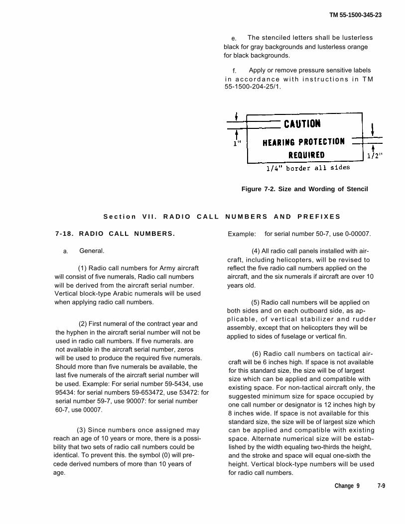
TM 55-1500-345-23
e. The stenciled letters shall be lusterlessblack for gray backgrounds and lusterless orangefor black backgrounds.
f. Apply or remove pressure sensitive labelsi n a c c o r d a n c e w i t h i n s t r u c t i o n s i n T M55-1500-204-25/1.
Figure 7-2. Size and Wording of Stencil
S e c t i o n V I I . R A D I O C A L L N U M B E R S A N D P R E F I X E S
7-18 . RADIO CALL NUMBERS.
a. General.
(1) Radio call numbers for Army aircraftwill consist of five numerals, Radio call numberswill be derived from the aircraft serial number.Vertical block-type Arabic numerals will be usedwhen applying radio call numbers.
(2) First numeral of the contract year andthe hyphen in the aircraft serial number will not beused in radio call numbers. If five numerals. arenot available in the aircraft serial number, zeroswill be used to produce the required five numerals.Should more than five numerals be available, thelast five numerals of the aircraft serial number willbe used. Example: For serial number 59-5434, use95434: for serial numbers 59-653472, use 53472: forserial number 59-7, use 90007: for serial number60-7, use 00007.
(3) Since numbers once assigned mayreach an age of 10 years or more, there is a possi-bility that two sets of radio call numbers could beidentical. To prevent this. the symbol (0) will pre-cede derived numbers of more than 10 years ofage.
Example: for serial number 50-7, use 0-00007.
(4) All radio call panels installed with air-craft, including helicopters, will be revised toreflect the five radio call numbers applied on theaircraft, and the six numerals if aircraft are over 10years old.
(5) Radio call numbers will be applied onboth sides and on each outboard side, as ap-p l i cab le , o f ve r t i ca l s tab i l i ze r and rudderassembly, except that on helicopters they will beapplied to sides of fuselage or vertical fin.
(6) Radio call numbers on tactical air-craft will be 6 inches high. If space is not availablefor this standard size, the size will be of largestsize which can be applied and compatible withexisting space. For non-tactical aircraft only, thesuggested minimum size for space occupied byone call number or designator is 12 inches high by8 inches wide. If space is not available for thisstandard size, the size will be of largest size whichcan be applied and compatible with existingspace. Alternate numerical size will be estab-lished by the width equaling two-thirds the height,and the stroke and space will equal one-sixth theheight. Vertical block-type numbers will be usedfor radio call numbers.
Change 9 7-9

TM 55-1500-345-23
b. Decals. Decalcomanias conforming toparagraph 6-5 may be used in lieu of paint whenapplying and maintaining radio call numbers onnon-tactical aircraft.
c. Prefix — National Guard. Army NationalGuard will have a compound prefix in black luster-less letters consisting of the state abbreviation(table 8-4) followed by a dash and letter "NG" in
the space normally occupied by “US ARMY”above the radio call numbers, Identification will.be applied on vertical fin of fixed wing aircraft andabove or adjacent to call numbers on rotary wingaircraft depending on space available. Letters wilbe 6 inches high in black color shade 37038.Where space is not available, the “NG” and stateabbreviation will be reduced to 2/3 its size toaccommodate space available
S e c t i o n V l l l . S E R I A L N U M B E R A N D F U E L S P E C I F I C A T I O N
7-19. FUSELAGE. The aircraft model desig- b. Location. On left side of aircraft in vicini-nation, serial number and fuel data will be applied ty of cockpit window.to all Army aircraft. See Chapters 9 and 10 forspecific guidance for a particular aircraft. Use c. Letters and numerals to be 7/8 in. plus orparagraph 7-20 if no specific guidance for a partic- minus 1/8 in. for model and serial number and 1/2ular aircraft is shown in Chapters 9 and 10. in. for fuel information.
7 - 2 0 . M A R K I N G S . S h o w a i r c r a f t t y p e ,serial number and specific fuel from operator’smanual.
a. Example.
U . S . A r m y U H - I D *U.S.A. Serial No. XX-XXXX
Service this aircraft with MIL-T-5624 GradeJP-4* Aviation Fuel. If not available, referto TB 55-9150-200-24 for Al ternate(Emergency) * fue l .
* Underlined items applicable to specific aircrafttypes.
7-10
TM 55-1500-345-23
SECTION IX MARKINGS FOR EMERGENCY ENTRY OR EXIT
7-21. GENERAL. Markings for emergency exit fromaircraft will be orange-yellow shade 33538. Emergencyentry will be marked with a broken band in the colorsspeci.ed in Chapters 9 and 10.
7-22. SECONDARY OPENINGS. Secondary open-ings, such as auxiliary exits, windows, and navigator’sdomes are usually smaller than primary openings,making entrance or exit more difficult. If the structureimmediately surrounding secondary openings is freefrom heavy structural members (such as bulkheads andmain longitudinal members), oxygen, fuel, and oil lines,and battery leads, it will be marked with a broken bandin the colors specified in Chapters 9 and 10. The bandwill be placed at the extreme boundary of the abovedescribed area, both inside and outside of the fuselage.Segments of the broken band will be 1/2 inch wide, 1inch long and approximately 12 inches apart. Wherethe band will be covered by soundproofing (or lining),the soundproofing (or lining), will also be marked. CUTHERE FOR EMERGENCY RESCUE will be markedor stenciled inside of, parallel with, and adjacent to,the broken band identifying the area on the outside ofthe aircraft where forced entry can be made for rescuepurposes. CUT HERE FOR EMERGENCY EXIT willbe marked on a similar location inside the aircraft.Letters will be 1 inch high. If the letters (on the skin) arecovered by soundproofing (or lining), the letters will alsobe marked on that part of the soundproofing (or lining)that covers that area.
7-23. RELOCATION. Each aircraft will be visually in-spected for areas which may be cut through for rescuewhen entrance or exit cannot be made in any other man-ner. Visual inspection must be used, as relocation andreinstallation of equipment and furnishings may havebeen made which would not be indicated on the instal-lation drawing of the aircraft. These areas should be asclose to normal stations of personnel as possible, ex-cept that they will not be placed at spots where personalinjury to occupants probably would result from forced en-try. Corner markings will be painted or stenciled on the
inside and outside of the fuselage marking the limits ofthese areas. The horizontal and vertical bars of the cor-ner markings will be 3 inches long and 1 inch wide. CUTHERE FOR EMERGENCY RESCUE will be painted orstenciled in the center of the four corner markings onthe outside of the aircraft and CUT HERE FOR EMER-GENCY EXIT will be placed in a similar location insidethe aircraft. Letters will be 1 inch high. Soundproofingalso will be painted if it covers markings or words. Thesemarkings need not be placed on aircraft so constructedthat openings could not be cut with safety.
Do not use a knife or metal blade on aircraftduring application procedure.
7-24. ESCAPE PANELS — INTERNALMARKINGS.
a. Markings for identification of escape hatches,doors, and exits on the inside of aircraft will be markedorange-yellow, shade No. 33538.
b. An orange-yellow #33538 broken band willmark the complete periphery of escape exits or doors.The broken band will be only on the door, and not on theframe of the door. Segments of the broken band will be1/2 inch wide, 1 inch long, and approximately 12 inchesapart (See MIL-A-25165). When the soundproofing (orlining) will cover the identification marking band on theinside of the aircraft, it will also be appropriately marked.
c. The words EMERGENCY EXIT in orange-yel-low No. 33538, will be marked or stenciled on the es-cape hatch, door, or exit, in the most readily visible lo-cation. Letters preferably will be 2 inches high, and willbe not less than 1 inch. If the letters (on the skin) arecovered by soundproofing (or lining), the letters also willbe stenciled on that part of the soundproofing (or lining).
Change 1 7-11
TM 55-1500-345-23
d. Small handles or levers used to actuate doorsor hatches shall be identified by alternate orange-yel-low and black stripes, 1/8 inch in width, painted on thebackground of the panel. Alternate orange-yellow andblack stripes 1/8 to 1/4 inch in width, shall be applieddirectly onto large levers or exit controls. Backgroundstriping shall be applied at a 45-degree angle from thevertical, rotated clockwise. Handles and small leversshall be striped with alternate colored rings. The stripingshall not interfere with other types of markings or cod-ings. Suitable descriptive wording, readily visible, will bemarked or stenciled on the door or structure of the air-craft, whichever is nearer to the emergency release, toidentify and explain its operation. This wording prefer-ably will be 1 inch high, and will be not less than 1/2 inchhigh. Standard English terminology will be used, suchas PULL, PUSH, TURN, or SLIDE.
e. Exits which are adequate for air, ground, andditching escape shall have the words EMERGENCYEXIT centered in the most visible location on the insideof the door or hatch.
f. Exits which are not adequate for all threephases of escape shall be marked EMERGENCY EXIT,
followed by the words AIR, GROUND, OR DITCHINGUSE ONLY, as applicable.
Example: GROUND USE ONLY, GROUND, ANDDITCHING USE ONLY, etc.
7-25. ESCAPE PANELS — EXTERNAL MARKINGS(NON-TACTICAL AIRCRAFT).
a. Markings identifying escape hatches, doors,and exits on the outside of aircraft will be markedgloss yellow on dark surfaces, and gloss black on lightsurfaces. If enamel is used, it will conform to FederalSpecification TT-E-489; if urethane is used, it will con-form to Military Specification MIL-C-83286.
b. All external releases for operation of emer-gency exit panels will be marked EXIT RELEASE onthe outside of the aircraft to facilitate quick identification.The wording that describes the operation of the exitrelease will be standard English terminology, such asPULL, PUSH, TURN, or SLIDE. Letters preferably willbe 2 inches high and will be not less than 1 inch high.
SECTION X MISCELLANEOUS MARKINGS
7-26. GENERAL. Markings of interior and exteriorsurfaces, labels, decals, placards, and stencils will beapplied in accordance with manufacturer’s instructions.The materials (polyurethane, lacquer or enamel) usedapplying the background will be the same as that usedto finish the surface. Installations in aircraft cockpitsof placards required by TB’s or MWO’s will be accom-plished by coating the back of the placard with a clearlacquer, varnish, or similar substance. The placardwill be further secured by an additional coat of clearlacquer, varnish, or similar substance over the front ofthe placard. If desired. such placards may be made ofphotosensitive anodized aluminum. Military Specifica-tion MIL-P-10524, Type H, or other metal, and attachedto the surface of the aircraft cockpit by bolts or screws.
7-27. BILINGUAL MARKINGS. Bilingual markingswill be applied to aircraft assigned to remote areaswhen authorized by the major Army field commander.
7-28. MARKINGS FOR TANK AREAS ANDINTERNAL STATION MARKINGS.
a. Data Markings. Additional data, such ascoolant mixture, water, alcohol mixture, oil tank levelrestrictions, and fuel grade (specified) will be appliednear the filler caps in letters 1/2 inch high.
b. Fuel Nozzle Groundings. The grounding re-ceptacle symbol indicates where the grounding plugshall be inserted to accomplish the grounding process.The symbol and lettering will be painted MIL-DTL-64159or MIL-DTL-53039, aircraft black, number 37038 perMIL-C-83413/9-2. See figure 7-12 for dimensions.
7-12 Change 12

TM 55-1500-345-23
c. Fuel Tank Filler Areas. Fuel tank fillercaps will be painted the same as the colorscheme of the aircraft. A 1 inch wide ring (an-nulus) with a 6.0 inch inside diameter (or as in-dicated in Chapter 9 or 10) will be painted aroundthe filler cap, black for tactical aircraft, red for allother paint schemes.
d. Internal Station and Compartment Mark-ings. When applicable, internal station andcompartment markings will be retained. Aircraft
-10 or the -20 manuals will be used to deter-mine station location. Station markings willpear as indicated in figure 8-4.
7-29. OXYGEN OUTLETS. Mark all ox-ygen outlets — WARNING, NO SMOKING WHILEOXYGEN IN USE.
7-30. L IFT POINTS. All lift points will
ap-
beindicated by an arrow pointing to the lift point.The word LIFT will be marked above the lift pointin letters 1/2 inch high. Notations, such as NOLIFT or NO PUSH, should be applied on areas ofaircraft which would be subject to damage bysuch action.
7-31 . S T R U T N U M B E R S . All wing strutswill be numbered with the part number. Thenumber will be located at the lower end, with thetop of the letters and numerals forward.
7 - 3 2 . E L E C T R I C A L C O N N E C T I O N S . Awarning will be painted at the points where it isnecessary to break electrical connections whenremoving wings, tail booms, or other assembliescontaining hidden wiring. The letters will be ofsufficient height to provide a permanent, distinct,and legible marking.
Example:
CAUTION
Disconnect electrical wiring beforeremoving wings.
7-33 . WALKWAYS. Areas immediately ad-jacent to the walkways will be marked NO STEP inaccordance with chapters 9 and 10.
7 - 3 4 . N A T O S Y M B O L M A R K I N G S O FAIRCRAFT SERVICING POINTS.
a. The U.S. Army has ratified a NATO Stan-dardization Agreement (STANAG) NO. 3109., ABCAIR STD 51/2, and STANAG 3230 which promul-gates standard aircraft markings. The standardmarkings will facilitate cross-servicing of NATOaircraft, thereby insuring more effective cross-service operat ions. NATO symbols wi l l beretained only on aircraft assigned to NATO areas.
b. The servicing and precautionary markingsof Army aircraft will be in accordance with thesymbols shown and described herein.
c. Symbols will be approximately 4 inches inthe longest dimension, except where otherwisespecified. However, smaller sized symbols maybe used if required by the item or area to be mark-ed. (See Chapter 8).
d. Lettering which supplements the symbolswill be in the scale of 1 to 4 in relation to the sym-bol. (See Chapter 8).
e. Access doors or panels to the servicingpoints will be marked with appropriate servicingsymbol or symbols.
7-13
TM55-1500-345-23
f. Normally markings will be in black, exceptground handling and safety point which will bemarked in orange.
g. Colors will be in accordance with FederalStandard FED-STD-595. The following basic col-o rS, which are specified with symbol or function,
will be used unless otherwise indicated:
COLOR NON-TACTICAL TACTICAL
Black No. 17038 37038
White No. 17875 37875
Red No. 11136 31136
Orange-yellow No. 13538 33538
Yellow No. 13655 33538
Green No. 14110 34110
h. For NATO symbols or codes on fuels andlubricants, refer to TB 34-9-25.
i. The symbols and colors are in accordancewith international agreements. (See Chapter 8).Any changes or recommendations will be pro-cessed through departmental standardization of-fices so that appropriate action may be takenrespecting the international agreement concern-ed.
7 - 3 5 . A I R C R A F T P L A T E S F O RGENERAL OFFICERS.
a. General. If desired, star plates may bedisplayed on Army aircraft. Star plates will bemounted on both sides of the aircraft; however aspecific location for mounting the plates is notprescribed herein due to the various designcharacteristics involved.
b. Material and Size, Plates wiII be con-structed of sheet metal 6 inches high by 9 incheswide.
c. Method o f Mark ing . Grade w i l l b edesignated by five-pointed white stars, 2 inches indiameter, with one point upward, equally spacedon the horizontal center of the line of the pIate.The plates will be painted with gloss red, shadeNo. 11136, and the 5 pointed stars will be paintedgloss white, shade No. 17875.
7 - 3 6 . J E T T I S O N A B L E C O M P O N E N T S .
a. Canopies. Jettisonable aircraft canopieswill have the aircraft serial number stenciled onthe outside of the canopy frame, on the left-handside, 6 inches from forward end. using 1-inchnumbers and letters provided sufficient space isavailable. If sufficient space is not available to ac-commodate 1-inch numbers and letters, they willbe as large as space permits. Also, aircraft utiliz-ing cartridge actuated devices will be marked inaccordance with Chapter 10.
b. Eject ion Seats . A black equi latera ltriangle with 9-inch sides and with apex pointingdownward, with the word DANGER on each sideof the triangle, will be applied on each side of thefuselage. The words EJECTION SEAT in black let-ters will be painted above the triangle. Additionalnotations will be optional.
7-37. FLUID LINE IDENTIFICATION.Fluid lines will be identified as specified in Mili-tary Standard MIL-STD-1247.
7 - 3 8 . S T O R A G E B A T T E R I E S . The no ta -tion “BATTERY LOCATION” with location givenwill be placed on the left side of the fuselage ortail boom as viewed from the rear of the aircraft.The label “BATTERY LOCATION” may be omittedonly if the battery access is located where labelwould normally be placed.
7-14 Change 1

TM55-1500-345-23
a. The fore and aft location of the markingwill be approximately in line with the trailing edgeof the wing.
b . The vertical location of the marking will beat a point 2 to 3 feet off the ground with theairplane in the wheels-up position and resting onthe ground, or in the case of airplanes having fix-ed landing gear, with the landing gear collapsed.When battery is accessible via a panel or door, thenotation “BATTERY ACCESS” will be marked inblock letters not less than 1/2 inch high on batteryaccess door. In the event of interference with win-dows, enclosures, etc. the marking will be placedas near the above mentioned location as prac-ticable. Either stencils, or a decalcomania, con-forming to paragraph 6-5 may be used to apply themarking.
c . The lettering of battery location will be 7/8inch plus or minus 1/8 inch in height. The markingwill be black shade No. 37038, on aircraft greenand gloss black, on aluminized or internationalorange and white painted surfaces.
7-39. AMERICAN FLAG DECALS.
a. The American flag will be applied to Armyaircraft which support relief operations outsidecontinental limits of the United States, unlessspecifically prohibited by the Unit Commander.
b. Decals should be placed in a horizontal posi-tion on each aircraft. Minimum decal size for CH-47 and larger aircraft should be 34 inches X 17-1/2inches, and for UH-60 and smaller aircraft, 17-3/4inches X 9-3/4 inches.
c. The American flag decal is to be positionedon vertical stabilizer of fixed wing aircraft, on CH-47, and the cargo door of Utility Rotary Wing Air-craft. Decals will be placed on major sheet metalstructure of medical service aircraft and otherrotary wing aircraft.
d. The American flag, when located on aircraft,should be positioned horizontally in such a man-ner that union (blue field) should be upper-mostwith stripes of the flag trailing at all times.
e. Flags printed on pressure-sensitive tapes areto be procured locally.
7 - 4 0 . D E S C R I P T I O N O F E X T E R I O RPAINT SYSTEM.
a . Use this paragraph if no specific guidancefor a particular aircraft is shown in Chapters 9 and10.
b. Show painter’s name or code, date, washPrimer (WP), primer (P), and top coat (L for lacquer,C for coatings, etc.) and quantity of coats. Paintercan be Government, for example, “NCAD”, orCommercial.
c . Example:
** WPI-P2-L3 Date
WP — indicates wash primer used
P — indicates primer used
L — indicates lacquer used (ifreq’d)
C — indicates coating used (ifreq’d)
d. Location. On left side of aircraft belowthe Serial Number and Fuel Specification. Alsoenter the above information in the applicable DAform 2408-15.
Change 1 7-15

TM55-1500-345-23
Section Xl. MARKING OF INSTRUMENTS
7-41 . GENERAL.
a. This Section provides the general method ofmarking aircraft instruments, the interpretation of thesemarkings, and specific instructions for the applicationof the markings.
NOTE
This Section is the subject of InternationalStandardization Agreement STANAG No.3 4 3 6 .
b. ACTUAL MARKINGS AND FUEL GRADE FORSPECIFIC AIRCRAFT.
The actual markings for specific aircraft and thefuel grade to which any set of markings apply may bedetermined by reference to the instrument markingspresented in the -10 Operator’s Manual for the aircraftinvolved.
c. INTERPRETATION OF THE RANGEMARKINGS.
The instrument range markings are designed to
indicate to the pilot, at a glance, that flight operation isbeing accomplished in a safe, desirable, or unsaferegion. Generally speaking the instrument markingsystem consists of four colors and intermediate blankspaces as illustrated in the fictitious instrument in figure7-3.
d. INDEX MARK.
The index mark is used to indicate any move-ment between the glass and the case and thus revealany errors in the location of the markers by such move-ment.
e. Deleted.
f . M I X T U R E C O N T R O L Q U A D R A N TMARKINGS.
These markings are used to identify the automaticlean and automatic rich positions on the controlquadrant.
7-16 Change 3

TM 55-1500-345-23
Change 1 7-17
Figure 7-3.Sample Markings
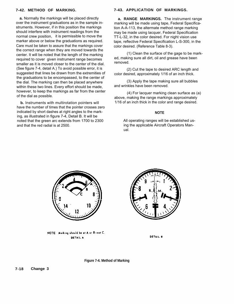
7-42. METHOD OF MARKING.
a. Normally the markings will be placed directlyover the instrument graduations as in the sample in-struments. However, if in this position the markingsshould interfere with instrument readings from thenormal crew position, it is permissible to move themarker above or below the graduations as required.Care must be taken to assure that the markings coverthe correct range when they are moved towards thecenter. It will be noted that the length of the markingrequired to cover given instrument range becomessmaller as it is moved closer to the center of the dial.(See figure 7-4, detail A.) To avoid possible error, it issuggested that lines be drawn from the extremities ofthe graduations to be encompassed, to the center ofthe dial. The marking can then be placed anywherewithin these two lines. Every effort should be made,however, to keep the markings as far from the centerof the dial as possible.
b. Instruments with multirotation pointers willhave the number of times that the pointer crosses zeroindicated by short dashes at right angles to the mark-ing, as illustrated in figure 7-4, Detail B. It will benoted that the green arc extends from 1700 to 2300and that the red radial is at 2500.
7-43. APPLICATION OF MARKINGS.
a. RANGE MARKINGS. The instrument rangemarking will be made using tape, Federal Specifica-tion A-A-113, the altermate method range markingmay be made using lacquer, Federal SpecificationTT-L-32, in the color desired. For night vision usetape, reflective Federal Specification L-S-300, in thecolor desired. (Reference Table 8-3).
(1) Clean the surface of the gage to be mark-ed, making sure all dirt, oil and grease have beenremoved.
(2) Cut the tape to desired ARC length andcolor desired, approximately 1/16 of an inch thick.
(3) Apply the tape making sure all bubblesand wrinkles have been removed.
(4) For lacquer marking clean surface as (a)above, making the range markings approximately1/16 of an inch thick in the color and range desired.
NOTE
All operating ranges will be established us-ing the applicable Aircraft Operators Man-ual.
Figure 7-4. Method of Marking
7-18 Change 3

TM 55-1500-345-23
NOTE
Where conditions permit on 1 inch ond 2inch clamp mounted indicators, whichhave the numerals and graduations on theouter circumference of the dial the fluo-rescent range marks wilI be installed onthe front edge of the case just outside thecover glass. In those instances where theforegoing does not apply refer to theinstrument markings presented in the -10Operator’s Manual.
(5) After allowing the applied marker to air dry for30 minutes, trim to exact size and paint over the marker withanother coat of varnish.
NOTE
If it is desired to remove any excess var-nish, this may be done within 1/2 hourafter application with a cloth dampenedwith naphtha.
b. INDEX MARK. A white index mark not over 1/16-inch wide will be painted across the joint between the glassand the case at the bottom of the center (6 o’ clock) position,or in the uncalibrated area of all instruments having rangemarkings on the glass. On panel installed clamp mount typeinstruments, the mark will be extended across the edge ofthe instrument case onto the mounting panel. On clampmount type instruments, not panel installed, the mark will beextended across the rim of the case, onto the case. On instru-ments utilizing the entire circumference of the dial for cali-bration increments the location of the index mark will beleft to the discretion of the using activity.
c. MIXTURE CONTROL QUADRANT MARKINGS.Mark the automatic lean position with gloss cellulose nitratelacquer, light blue, Federal Specification TT-L-32. Mark theautomatic rich position with gloss cellulose nitrate lacquer,light green, Federal Specification TT-L-32. (See figure 7-5).
Figure 7-5. Mixture Control Quadrant
NOTE
The following paragraphs describing themarkings for the various types of instru-ments attempt to cover all possible mark-ings for each instrument. It should benoted that the illustrated instruments aretypical and may or may not include all themarkings mentioned in the descriptiveparagraphs.
NOTE
It is not intended in this technical manualto set forth the exact ranges to be coveredby these instrument markings for all air-craft but to illustrate the correct method ofmarking the various types of instruments.For example, the manifold pressure gage(figure 7-6 detail A) shows a takeoff valueof 49 inches; for one aircraft it might be55 inches; for another it might be 72 inch-es; for another, 100 inches, and the like.The exact ranges to be covered on eachinstrument for a given aircraft can bydetermined only through reference to theinstrument marking page of the appropri-ate -10 Operator’s Manual.
Change 5 7-19

TM55-1500-345-23
7-44. MARKINGS FOR RECIPROCATING ENGINE AIRCRAFT
a. MANIFOLD PRESSURE GAGE. (See figure 7-6, detail A.)
(1) BLUE ARC. Indicates the range within whichoperation is permitted in auto-lean. The bottom of thisarc indicates the minimum manifold pressure desirablein flight determined by engine characteristics. Thetop of this arc indicates the manifold pressure at whichmixture control must be moved into auto-rich.
(2) GREEN RADIAL OR ARC. Describes the rangewithin which operation must be in auto-rich. Theradial or top of this arc indicates maximum continuouspower. All operation above this manifold pressure islimited in time (usually 5 or 15 minutes).
(3) SHORT RED RADIAL.. Indicates manifold pres-sure for takeoff.
(4) LONG RED RADIAL. Indicates maximum drywar emergency manifold pressure.
(5) LONG RED RADIAL. Indicates maximum waremergency manifold pressure with water injection.
b. TACHOMETER. (See figure 7-6, detail B.)
(1) BLUE ARC. Indicates rpm range within whichauto-lean, operation is permitted. The bottom of thisarc indicates the minimum rpm desirable in flightbecause of engine limitations, generator cut-out, etc.The top of this arc indicates the rpm at which the mix-ture control must be moved to auto-rich.
(2) GREEN RADIAL OR ARC. Indicates rpm rangewithin which auto-rich operation is required. Theradial or top of this arc indicates maximum continuouspower. All operation above this rpm is limited in time(usually 5 or 15 minutes).
(3) RED RADIAL. Indicates maximum rpm.
(4) RED ARC. May be used to show region ofprohibited operation because of dangerous vibration orsimilar reasons.c. CYLINDER HEAD TEMPERATURE GAGE. (See
figure 7-6, detail C.)
(1) BLUE ARC. Indicates the range within whichoperation is permitted in auto-Iean. The bottom of thisarc indicates the minimum temperature desirable forflight (minimum engine warmth required for good fuelvaporization and efficient engine operation). The topof this arc indicates the temperature at which the mix-ture control must be moved to auto-rich.
(2) GREEN ARC. Describes the range withinwhich operation must be in auto-rich. The top of this
arc indicates maximum continuous power; all operationabove this temperature is limited in time (usually 5or 15 minutes).
(3) RED RADIAL. Indicates maximum permissibletemperature.
d. CARBURETOR AIR TEMPERATURE GAGE.(See figure 7-6, detail D.)
(1) YELLOW ARC. Indicates the temperature rangewithin which undesirable conditions may exist such asdanger of icing or poor fuel vaporization.
(2) GREEN ARC. Indicates the temperature rangeo! best operation and assures good vaporization.
(3) RED RADIAL. Indicates maximum permissibletemperature, usually because of detonation danger.
e. COOLANT TEMPERATURE GAGE. (See figure7-7, detail A.)
(1) GREEN ARC. Describes the range withinwhich the temperature must remain during continuousoperation. The bottom of this arc indicates minimumdesirable temperature for flight. The top of this arcindicates maximum continuous power. All operationabove this temperature is limited in time (usually 5 or15 minutes).
(2) RED RADIAL. Indicates maximum permissibletemperature.
(3) RED RADIAL. Indicates war emergency maxi-mum temperature.
f. TORQUEMETER. (See figure 7-7, detail B.)
(1) BLUE ARC. Indicates the range within whichoperation is permitted in auto-lean. The bottom of thisarc indicates the minimum torque pressure desirablein flight determined by engine characteristics. Thetop of this arc indicates the torque pressure at whichmixture control must be moved into auto-rich.
(2) GREEN RADIAL OR ARC. Describes therange within which operation must be in auto-rich.The radial or top of this arc indicates maximum con-tinuous power. All operation above this torque pressureis limited in time (usually 5 or 15 minutes).
(3) SHORT RED RADIAL. Indicates maximum drytorque pressure.
(4) LONG RED RADIAL. Indicates maximum wettorque pressure.
7-20 Change 1

Figure 7-6. Typical Manifold Pressure Gage, Tachometer, Cylinder Head Temperature Gage, and Air Temperature Gage Markings.
Change 1 7-21

TM 55-1500-345-23
Figure 7-7. Typical Coolant Temperature Gage and Torquemeter Markings
7-22 Change 1

TM 55-1500-345-23
7-45. MARKINGS FOR JET ENGINE AIRCRAFT
a. TACHOMETER. (See figure 7-8, detail A.)
(1) GREEN ARC. Describes the range within whichthe rpm must falI during continuous flight operation.The bottom of this arc describes the minimum rpmfor best cruising. Considerable range will be lostwhen operating below this rpm. The top of this arcindicates maximum continuous rpm; operation abovewhich is limited to a specified length of time.
(2) RED RADIAL. Indicates maximum rpm.(3) RED ARC. May be used to show region of pro-
hibited operation because of dangerous vibration orsimilar reasons.
b. EXHAUST TEMPERATURE GAGE. (See figure 7-8,detail B.)
(1) RED RADIAL. Indicates minimum permissibletemperature during flight.
(2) GREEN ARC. Indicates desirable temperatureduring continuous operation.
(3) RED RADIAL. Indicates maximum permissibletemperature for flight.
(4) RED RADIAL. Indicates maximum permissibletemperature during starting or acceleration.
Figure 7-8. Typical Tachometer and Engine Exhaust Temperature Gage Markings
Change 1 7-23
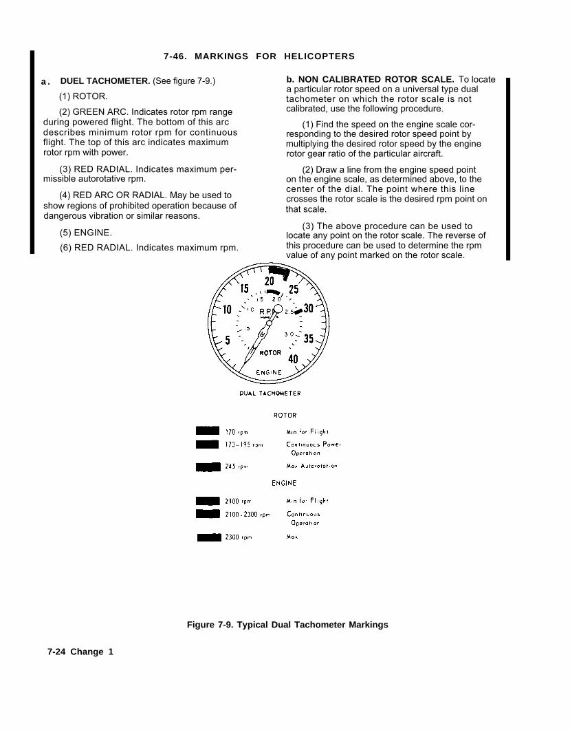
a .
7-46. MARKINGS FOR HELICOPTERS
DUEL TACHOMETER. (See figure 7-9.) b. NON CALIBRATED ROTOR SCALE. To locate
(1) ROTOR.
(2) GREEN ARC. Indicates rotor rpm rangeduring powered flight. The bottom of this arcdescribes minimum rotor rpm for continuousflight. The top of this arc indicates maximumrotor rpm with power.
(3) RED RADIAL. Indicates maximum per-missible autorotative rpm.
(4) RED ARC OR RADIAL. May be used toshow regions of prohibited operation because ofdangerous vibration or similar reasons.
a particular rotor speed on a universal type dualtachometer on which the rotor scale is notcalibrated, use the following procedure.
(1) Find the speed on the engine scale cor-responding to the desired rotor speed point bymultiplying the desired rotor speed by the enginerotor gear ratio of the particular aircraft.
(2) Draw a line from the engine speed pointon the engine scale, as determined above, to thecenter of the dial. The point where this linecrosses the rotor scale is the desired rpm point onthat scale.
(5) ENGINE.(3) The above procedure can be used to
locate any point on the rotor scale. The reverse of(6) RED RADIAL. Indicates maximum rpm. this procedure can be used to determine the rpm
value of any point marked on the rotor scale.
Figure 7-9. Typical Dual Tachometer Markings
7-24 Change 1

TM55-1500-345-23
7-47. MARKINGS FOR ALL AIRCRAFT
a. OIL PRESSURE GAGE. (See figure 7-10, detailA.)
(1) LOWER RED RADIAL. Indicate. minimum oilpressure permissible in flight.
(2) GREEN ARC. Indicates desirable oil pressurerange during continuous operation.
(3) UPPER RED RADIAL. Indicates maximum per-missible oil pressure.
b. OIL TEMPERATURE GAGE. (See figure 7-10,detail B.)(1) LOWER RED RADIAL. Indicates minimum per-
missible temperature during flight.(2) GREEN ARC. Indicates desirable temperature
during continuous operation.
(3) UPPER RED RADIAL. Indicates maximum per-missible temperature.
c. AIRSPEED INDICATOR. (See figure 7-10,details C and D.)
(1) YELLOW RADIAL. Indicates maximum per-missible airspeed with either full flaps or landinggear extended. When the maximum permissible speedwith flaps down differs from that with gear down, thelower speed and condition will be given. A notationin parenthesis will also be included to show the higherlimiting speed and condition.
(2) RED RADIAL. Indicates maximum permissiblediving speed at design gross weight.
(3) YELLOW ARC. Defines the range of maximumpermissible diving speeds from maximum to designgross weight.
d. ACCELEROMETER. (See figure 7-11, detail A.)
(1) RED RADIAL. Indicates maximum permissiblepositive acceleration at maximum gross weight.
(2) RED RADIAL. Indicates maximum permissiblepositive acceleration at design gross weight.
(3) RED RADIAL. Indicates maximum permissiblenegative acceleration at maximum gross weight.
e. HYDRAULIC PRESSURE GAGE. (See figure 7-11, detail B.)
(1) YELLOW RADIAL. Indicates pressure re-quired for one brake application.
(2) GREEN ARC. Indicates normal operating pres-sure. The lower end of this arc indicates hydraulicpump cut-in pressure and the upper end indicates cut-out pressure.
(3) RED RADIAL. Indicates maximum permissiblepressure.
f. SUCTION GAGE. (See figure 7-11, detail C.)
(1) RED RADIAL. Indicates minimum desirablesuc t ion .
(2) GREEN ARC. Indicates desirable suctionrange.
(3) RED RADIAL. Indicates maximum desirables u c t i o n .
g. DEICER GAGE. (See figure 7-11, detail D.)
(1) GREEN ARC.range.
(2) RED RADIAL.pressure.
Indicates desirable pressure
Indicates maximum permissible
h. FUEL PRESSURE GAGE. (See figure 7-11, detailE.)Same as oil pressure gage. (Refer to sub-
paragraph a).
Change 1 7-25
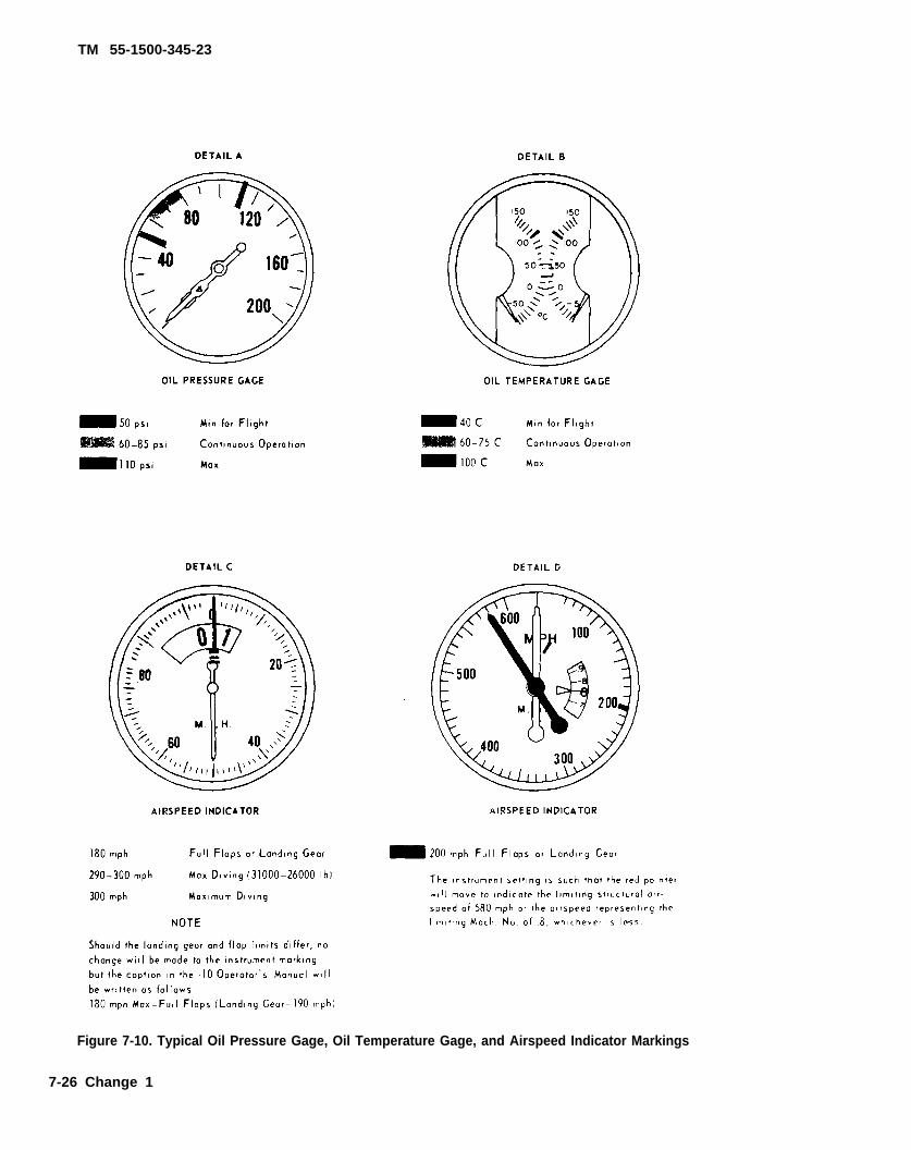
TM 55-1500-345-23
Figure 7-10. Typical Oil Pressure Gage, Oil Temperature Gage, and Airspeed Indicator Markings
7-26 Change 1

TM 55-1500-345-23
Figure 7-11. Typical Accelerometer, Hydraulic Pressure Gage, Deicer Gage, and Fuel Pressure Goge Markings.
Page 7-28 has been deleted. Change 3 7-27


TM 55-1500-345-23
Figure 7-12. Fuel Nozzle Ground Dimensions.
Change 5 7-29/(7-30 blank)


TM 55-1500-345-23
CHAPTER 8MISCELLANEOUS TABLES AND ILLUSTRATIONS
Table 8-1. Technical Manuals, Technical Bulletins, and AR’s
TM 5-618 Painting, Repairs and Utilities
TB 55-9150-200-24 Engine and Transmission Oil, Fuels, and Additives forArmy Aircraft
TM 1-1500-344-23 Series Aircraft Weapons Systems Cleaning and CorrosionControl
AR 200-1 Environmental Protection and Enhancement
TB 43-0101 Handling, Storage and Disposal of Army Aircraftcomponents containing Radioactive Materials
TB 43-0242 WD Carc Spot Painting
TB MED 501 Occupational and Environmental Health: Hearingconservation
TB MED 502 Occupational and Environmental Health: RespiratoryProtection Program
TM 1-1500-204-23 (Series) General Aircraft Maintenance Manual
Table 8-2. Standards-American Society for Testing and Materials (ASTM) D1193-Reagent Water
Federal Standard 595 - Colors
Military Standard 795 - Colors
Change 12 8-1
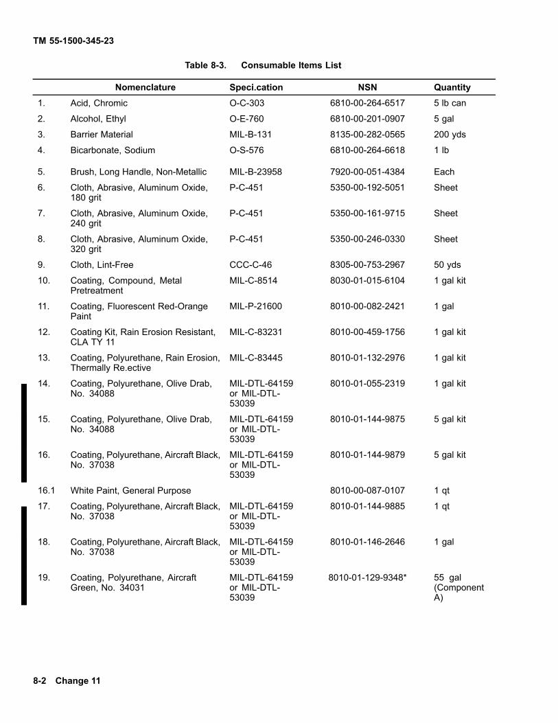
TM 55-1500-345-23
Table 8-3. Consumable Items List
Nomenclature Speci.cation NSN Quantity1. Acid, Chromic O-C-303 6810-00-264-6517 5 lb can
2. Alcohol, Ethyl O-E-760 6810-00-201-0907 5 gal
3. Barrier Material MIL-B-131 8135-00-282-0565 200 yds
4. Bicarbonate, Sodium O-S-576 6810-00-264-6618 1 lb
5. Brush, Long Handle, Non-Metallic MIL-B-23958 7920-00-051-4384 Each
6. Cloth, Abrasive, Aluminum Oxide,180 grit
P-C-451 5350-00-192-5051 Sheet
7. Cloth, Abrasive, Aluminum Oxide,240 grit
P-C-451 5350-00-161-9715 Sheet
8. Cloth, Abrasive, Aluminum Oxide,320 grit
P-C-451 5350-00-246-0330 Sheet
9. Cloth, Lint-Free CCC-C-46 8305-00-753-2967 50 yds
10. Coating, Compound, MetalPretreatment
MIL-C-8514 8030-01-015-6104 1 gal kit
11. Coating, Fluorescent Red-OrangePaint
MIL-P-21600 8010-00-082-2421 1 gal
12. Coating Kit, Rain Erosion Resistant,CLA TY 11
MIL-C-83231 8010-00-459-1756 1 gal kit
13. Coating, Polyurethane, Rain Erosion,Thermally Re.ective
MIL-C-83445 8010-01-132-2976 1 gal kit
14. Coating, Polyurethane, Olive Drab,No. 34088
MIL-DTL-64159or MIL-DTL-53039
8010-01-055-2319 1 gal kit
15. Coating, Polyurethane, Olive Drab,No. 34088
MIL-DTL-64159or MIL-DTL-53039
8010-01-144-9875 5 gal kit
16. Coating, Polyurethane, Aircraft Black,No. 37038
MIL-DTL-64159or MIL-DTL-53039
8010-01-144-9879 5 gal kit
16.1 White Paint, General Purpose 8010-00-087-0107 1 qt
17. Coating, Polyurethane, Aircraft Black,No. 37038
MIL-DTL-64159or MIL-DTL-53039
8010-01-144-9885 1 qt
18. Coating, Polyurethane, Aircraft Black,No. 37038
MIL-DTL-64159or MIL-DTL-53039
8010-01-146-2646 1 gal
19. Coating, Polyurethane, AircraftGreen, No. 34031
MIL-DTL-64159or MIL-DTL-53039
8010-01-129-9348* 55 gal(ComponentA)
8-2 Change 11

TM 55-1500-345-23
Table 8-3. Consumable Items List — Continued
Nomenclature Speci.cation NSN Quantity20. Coating, Polyurethane, Aircraft
Green, No. 34031MIL-DTL-64159or MIL-DTL-53039
8010-01-131-6255 1 gal
21. Coating, Polyurethane, AircraftGreen, No. 34031
MIL-DTL-64159or MIL-DTL-53039
8010-01-131-6262 5 gal
22. Coating, Polyurethane, AircraftGreen, No. 34031
MIL-DTL-64159or MIL-DTL-53039
8010-01-141-2420 1 qt
23. Coating, Polyurethane, Aircraft Gray,Exterior, No. 36300
MIL-DTL-64159or MIL-DTL-53039
8010-01-127-8908 1 gal
24. Coating, Polyurethane, Aircraft Gray,Exterior, No. 36300
MIL-DTL-64159or MIL-DTL-53039
8010-01-144-9876 5 gal
25. Coating, Polyurethane,Orange/Yellow, No. 33538
MIL-DTL-64159or MIL-DTL-53039
26. Coating, Polyurethane, Aircraft Gray,Exterior, No. 36300
MIL-DTL-64159or MIL-DTL-53039
8010-01-144-9882 1 qt
27. Coating, Polyurethane, Aircraft Gray,Interior, No. 36231
MIL-DTL-64159or MIL-DTL-53039
8010-01-146-2649 1 gal
28. Coating, Polyurethane, Aircraft Red,No. 31136
MIL-DTL-64159or MIL-DTL-53039
8010-01-144-9873 1 gal
29. Coating, Polyurethane, Aircraft Red,No. 31136
MIL-DTL-64159or MIL-DTL-53039
8010-01-144-9878 5 gal
30. Coating, Polyurethane, Aircraft Red,No. 31136
MIL-DTL-64159or MIL-DTL-53039
8010-01-144-9884 1 qt
31. Coating, Polyurethane, AircraftWhite, No. 37875
MIL-DTL-64159or MIL-DTL-53039
8010-01-144-9872 1 gal
32. Coating, Polyurethane, AircraftWhite, No. 37875
MIL-DTL-64159or MIL-DTL-53039
8010-01-144-9877 5 gal
33. Coating, Polyurethane, AircraftWhite, No. 37875
MIL-DTL-64159or MIL-DTL-53039
8010-01-144-9883 1 qt
Change 11 8-3

TM 55-1500-345-23
Table 8-3. Consumable Items List — Continued
Nomenclature Specification NSN Quantity34. Coating, Polyurethane, Component
B (for all 55 gallon drum kits)MIL-DTL-64159or MIL-DTL-53039
8010-01-132-0205** 55 gal
35. Coating, Polyurethane, Dark Sand MIL-DTL-64159or MIL-DTL-53039
1 gal
36. Coating, Polyurethane, Insignia Blue,No. 35044
MIL-DTL-64159or MIL-DTL-53039
8010-01-144-9880 5 gal
37. Coating, Polyurethane, Insignia Blue,No. 35044
MIL-DTL-64159or MIL-DTL-53039
8010-01-144-9887 1 qt
38. Coating, Polyurethane Insignia Blue,35044
MIL-DTL-64159or MIL-DTL-53039
8010-01-146-2648 1 gal
39. DELETED40. Coating, Walkway, Type II MIL-W-5044 5610-00-641-0427 1 gal41. Compound, Sealing MIL-S-7124 8030-00-024-9634 1 pt42. Dichloromethane MIL-D-6998 6810-00-244-0290 5 gal43. Dichromate, Potassium O-P-559 6810-00-264-6525 5 lb44. Ethylene, Glycol, Monoethyl Ether
AcetateMIL-E-7125 6810-00-263-0563 1 Gal can
45. Films, Chemical, Corrosion Resistantfor Aluminum, Class 1A
MIL-C-5541 8030-00-811-3723 2 lb can
46. Foil, Metal, 5052 Aluminum Alloy QQ-A-1876 9535-00-541-2453 Roll
47. Lacquer, Lusterless Black, Shade37038
MIL-L-19538 8010-00-527-2884 1 gal
48. Lacquer, Black MIL-DTL-53059or MIL-DTL-64159
8010-01-042-9438 1 gal
49. Lacquer, Gray No. 36231 TT-L-20 8010-00-515-1568 1 gal can50. Lacquer, Cellulose Nitrate Aluminum,
Shade 17178TT-L-32 8010-00-241-8406 1 gal
51. Lacquer, Gray Shade 36231 TT-L-20 8010-00-515-1568 1 gal52. Lacquer, Lusterless Aircraft Green MIL-DTL-53059
or MIL-DTL-64159
8010-00-083-6588 5 gal can
53. Lacquer, Lusterless Aircraft Green MIL-DTL-53059or MIL-DTL-64159
8010-01-033-8917 1 gal
53.1 Lacquer, Acrylic, Blue Shade 15044 MIL-PRF-81352C 8010-00-551-7933 1 Gal53.2 Lacquer, Acrylic, Green Shade 14187 MIL-PRF-81352C 8010-00-527-2483 1 Gal
53.3 Lacquer, Acrylic, Red Shade 11136 MIL-PRF-81352C 8010-00-551-7934 1 Qt
8-4 Change 12
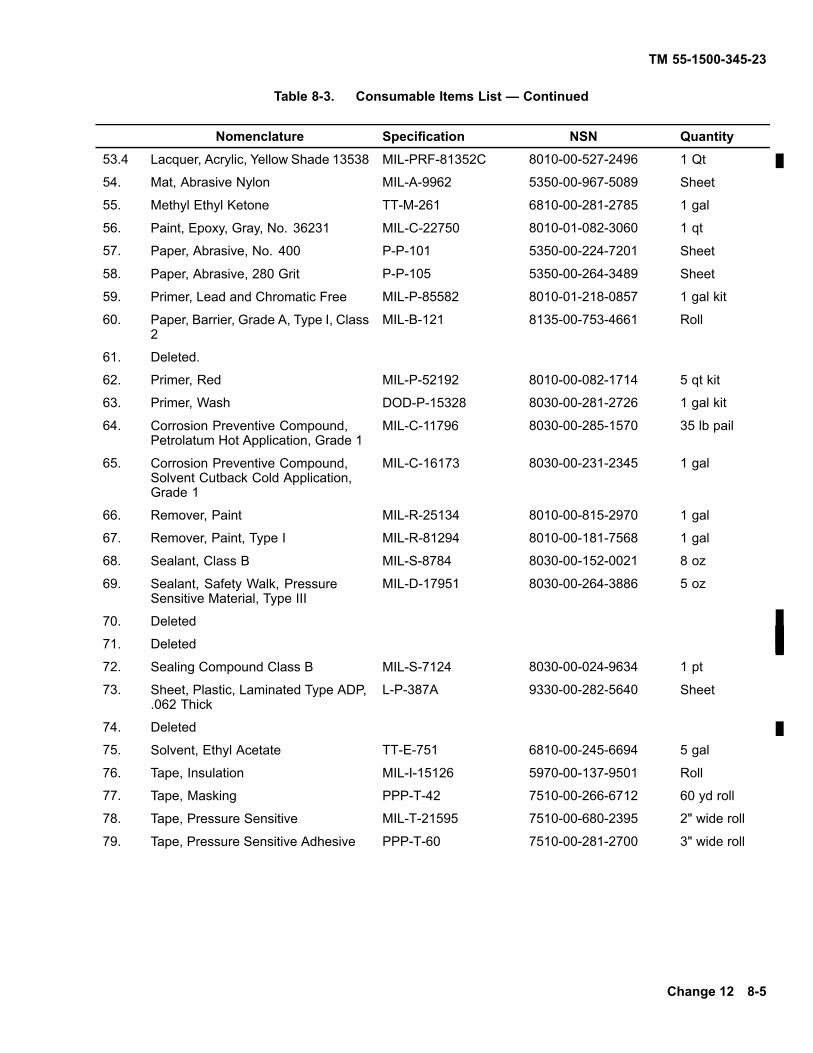
TM 55-1500-345-23
Table 8-3. Consumable Items List — Continued
Nomenclature Specification NSN Quantity53.4 Lacquer, Acrylic, Yellow Shade 13538 MIL-PRF-81352C 8010-00-527-2496 1 Qt
54. Mat, Abrasive Nylon MIL-A-9962 5350-00-967-5089 Sheet
55. Methyl Ethyl Ketone TT-M-261 6810-00-281-2785 1 gal
56. Paint, Epoxy, Gray, No. 36231 MIL-C-22750 8010-01-082-3060 1 qt
57. Paper, Abrasive, No. 400 P-P-101 5350-00-224-7201 Sheet
58. Paper, Abrasive, 280 Grit P-P-105 5350-00-264-3489 Sheet
59. Primer, Lead and Chromatic Free MIL-P-85582 8010-01-218-0857 1 gal kit
60. Paper, Barrier, Grade A, Type I, Class2
MIL-B-121 8135-00-753-4661 Roll
61. Deleted.
62. Primer, Red MIL-P-52192 8010-00-082-1714 5 qt kit
63. Primer, Wash DOD-P-15328 8030-00-281-2726 1 gal kit
64. Corrosion Preventive Compound,Petrolatum Hot Application, Grade 1
MIL-C-11796 8030-00-285-1570 35 lb pail
65. Corrosion Preventive Compound,Solvent Cutback Cold Application,Grade 1
MIL-C-16173 8030-00-231-2345 1 gal
66. Remover, Paint MIL-R-25134 8010-00-815-2970 1 gal
67. Remover, Paint, Type I MIL-R-81294 8010-00-181-7568 1 gal
68. Sealant, Class B MIL-S-8784 8030-00-152-0021 8 oz
69. Sealant, Safety Walk, PressureSensitive Material, Type III
MIL-D-17951 8030-00-264-3886 5 oz
70. Deleted
71. Deleted
72. Sealing Compound Class B MIL-S-7124 8030-00-024-9634 1 pt
73. Sheet, Plastic, Laminated Type ADP,.062 Thick
L-P-387A 9330-00-282-5640 Sheet
74. Deleted
75. Solvent, Ethyl Acetate TT-E-751 6810-00-245-6694 5 gal
76. Tape, Insulation MIL-I-15126 5970-00-137-9501 Roll
77. Tape, Masking PPP-T-42 7510-00-266-6712 60 yd roll
78. Tape, Pressure Sensitive MIL-T-21595 7510-00-680-2395 2" wide roll
79. Tape, Pressure Sensitive Adhesive PPP-T-60 7510-00-281-2700 3" wide roll
Change 12 8-5

TM 55-1500-345-23
Table 8-3. Consumable Items List — Continued
Nomenclature Specification NSN Quantity80. Tape, Pressure Sensitive Adhesive,
Type IIMIL-T-23397 7510-00-473-9513 2" wide roll
80.1 Tape, Pressure Sensitive, Blue A-A-113 7510-00-550-7124 1/2 X 2592 inroll
80.2 Tape, Pressure Sensitive, Green A-A-113 7510-00-550-7129 1/2 X 2592 inroll
80.3 Tape, Pressure Sensitive, Red A-A-113 7510-00-550-7126 1/2 X 2592 inroll
80.4 Tape, Pressure Sensitive, Yellow A-A-113 7510-00-550-7125 1/2 X 2592 inroll
80.5 Tape, Pressure A-A113 7510-00-550-7127
80.6 Tape, Reflective, Yellow L-S-300 9390-00-057-4545 50 yd roll
80.7 Tape, Reflective, Green L-S-300 9390-00-106-2466 50 yd roll
80.8 Tape, Reflective, Red L-S-300 9390-00-106-2467 50 yd roll
81. Thinner MIL-T-6096 8010-00-165-5582 1 gal
82. Thinner, Aliphatic PolyurethaneCoating
MIL-T-81772 8010-00-181-8080 1 gal
83. Thinner, Lacquer TT-T-266 8010-00-160-5787 1 gal
84. Toluene TT-T-548 6810-00-290-0048 5 gal
85. Xylene ASTM D 846 6810-00-584-4070 5 gal
86. Deleted
87. Urethane, Gloss MIL-C-83286 Local Purchase ***
88. Varnish, Acid-Proof TT-V-51 8010-00-160-5856 5 gal
89. Wax, Paraffin VV-W-95 9160-00-285-2044 1 lb cake
90. Wool, Aluminum MIL-A-4864 5350-00-286-4851 1 lb
91. Litmus, Paper AC (Blue) MS 36253-2 6640-00-290-0146 100 ea
92. Litmus, Paper AC (Red) MS 36253-1 6640-00-290-0147 100 ea
93. Paint Heat Resistant, Gray MIL-P-14105 8010-00-877-6415 1 gal
94. Lacquer, Aluminum, Heat Resisting,Shade 17178
TT-P-28 8010-00-815-2592 1 gal
95. Paint, Heat Resisting Shade 34087 MIL-P-14105 8010-00-616-4009 1 gal
96. Epoxy Primer Coating MIL-P-53022 8010-01-193-0516 1 qt kit
8-6 Change 11
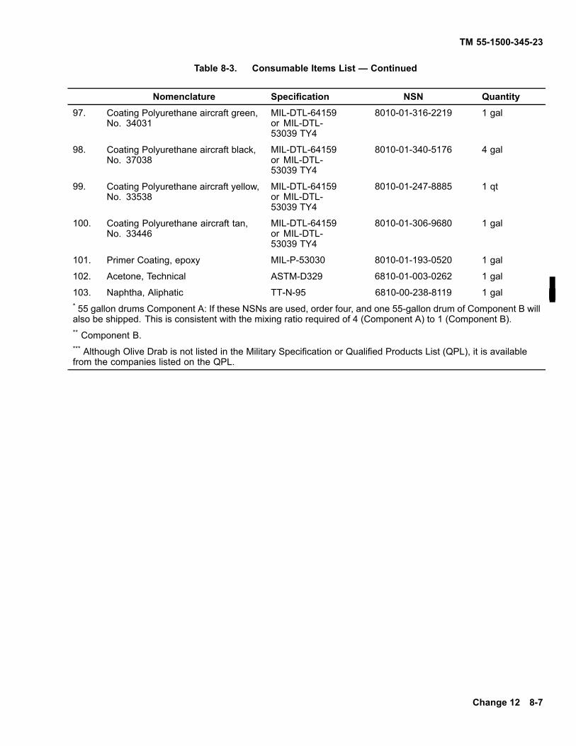
TM 55-1500-345-23
Table 8-3. Consumable Items List — Continued
Nomenclature Specification NSN Quantity97. Coating Polyurethane aircraft green,
No. 34031MIL-DTL-64159or MIL-DTL-53039 TY4
8010-01-316-2219 1 gal
98. Coating Polyurethane aircraft black,No. 37038
MIL-DTL-64159or MIL-DTL-53039 TY4
8010-01-340-5176 4 gal
99. Coating Polyurethane aircraft yellow,No. 33538
MIL-DTL-64159or MIL-DTL-53039 TY4
8010-01-247-8885 1 qt
100. Coating Polyurethane aircraft tan,No. 33446
MIL-DTL-64159or MIL-DTL-53039 TY4
8010-01-306-9680 1 gal
101. Primer Coating, epoxy MIL-P-53030 8010-01-193-0520 1 gal
102. Acetone, Technical ASTM-D329 6810-01-003-0262 1 gal
103. Naphtha, Aliphatic TT-N-95 6810-00-238-8119 1 gal* 55 gallon drums Component A: If these NSNs are used, order four, and one 55-gallon drum of Component B willalso be shipped. This is consistent with the mixing ratio required of 4 (Component A) to 1 (Component B).** Component B.*** Although Olive Drab is not listed in the Military Specification or Qualified Products List (QPL), it is availablefrom the companies listed on the QPL.
Change 12 8-7

TM 55-1500-345-23
Table 8-4. State Abbreviations
Alaska AK Montana MT
Alabama AL Nebraska NE
Arizona AZ Nevada NV
Arkansas AR New Hampshire NH
California CA New Jersey NJ
Colorado CO New Mexico NM
Connecticut CT New York NY
Delaware DE North Carolina NC
District of Columbia DC North Dakota ND
Florida FL Ohio OH
Georgia GA Oklahoma OK
Guam GU Oregon OR
Hawaii HI Pennsylvania PA
Idaho ID Puerto Rico PR
Illinois IL Rhode Island RI
Indiana IN South Carolina SC
Iowa IA South Dakota SD
Kansas KS Tennessee TN
Kentucky KY Texas TX
Louisiana LA Utah UT
Maine ME Vermont VT
Maryland MD Virginia VA
Massachusetts MA Virgin Islands VI
Michigan MI Washington WA
Minnesota MN West Virginia WV
Mississippi MS Wisconsin WI
Missouri MO Wyoming WY
8-8 Change 11

TM55-1500-345-23
Table 8-5. Definitions of Common Painting Terms
Common Painting Terms Definitions
Abrasion Resistance The resistance of a surface to being worn by rubbing or friction.
Acrylic A family of synthetic resins made by polymerizing esters of acrylicacids.
Aliphatic The name applied to petroleum products which are straight-chainhydrocarbons derived from a paraffin-base crude oil.
Alkyd Asynthetic resin which is the condensation product of a Polybasicacid such as phthalic, a polyhydric alcohol such as glycerin and anoil fatty acid.
Alligatoring A form of paint failure in which cracks form on the surface layer on-ly. It is caused by the application of thick films where the underly-ing surface remains relatively soft.
Binder The nonvolatile portion of a coating vehicle which is the film-forming ingredient used to bind the pigment particles together.
Bleeding A condition which exists when the color of a dye, stain or pigmentpasses through the top coat producing a stain. It occurs when thepigment is somewhat soluble in the vehicle of the top coat.
Blistering A paint film failure usually caused by application of paint on a sur-face containing an excessive amount of moisture or other volatilematerial.
Blushing
Catalyst
Chalking
Checking
Coalescence
Cobwebbing
A term applied to lacquers when they become partially opaque,cloudy or translucent upon application or drying. Fast-evaporatingsolvents may cool the film enough to cause water condensation,and resultant precipitation of solid materials.
A substance which accelerates the speed of a chemical reaction.
The presence of a loose powder on the surface of a paint after ex-posure to the elements.
A phenomenon manifested by slight breaks in the surface of thepaint film.
The fusing together of a latex film upon evaporation of water.
Same as webbing - see webbing.
8 - 9

TM55-1500-345-23
Table 8-5. Definitions of Common Painting Terms — Continued
Common Painting Terms Definitions
Color A generic term referring inclusively to all colors of the spectrum,and white and black. Color is described by three properties: hue, lightness and saturation.
(1) Hue (color, character, dominant wavelength), blue, green, red,
Color Retention
Compatibility
Corrosion
Crawling
Crocking
Defoamer
Dew Point
Diluent
Drier
Dry Bulb Temperature
Efflorescence
etc.
(2) Lightness (brightness, reflectance, value)scale between pure black and pure white.
(3) Saturation (purity, grayness, cleanliness,purity or intensity of color.
Color stability after exposure to the elements.
position on the gray
muddiness, chroma),
The ability of two or more materials to mix with each other withoutseparation or adverse reaction.
Detrimental change in a material usually a metal under condition ofexposure.
The tendency of a liquid to draw up because of high surface ten-sion.
Removal of color on abrasion or rubbing.
Products used for controlling undesirable foams.
The temperature at which the air becomes saturated with watervapor.
A liquid which is blended with an active solvent to reduce cost.
Any catalytic material which when added to a drying oil acceleratesdrying or hardening of the film.
The temperature as indicated by an ordinary thermometer.
A phenomenon whereby a whitish crust of fine crystals forms on apainted surface. These are usually sodium salts which diffusethrough the paint film from the substrate.
8-10

TM55-1500-345-23
Table 8-5. Definitions of Common Painting Terms — Continued
Common Painting Terms Definitions
Elastomeric Compound Any of a variety of elastic compounds resembling rubber. Rubber isan elastomeric compound.
Emulsifier A material which when added to a mixture of dissimilar materialssuch as oil and water will produce a stable homogeneous emulsion.
Emulsion
False Body
Faying Surfaces
Firepoint
Flash Point
Hue
Hydrogen Embrittlement
Hydrophilic
Hydrophobic
Hygroscopic
Immiscible
Incompatible
Inert
A suspension of fine particles of globules of a liquid within a liquid.
A composition which thins down on stirring is said to exhibit falsebody.
Surfaces fitted or joined closely or tightly.
The temperature at which a material takes fire without flame froman external source.
Lowest temperature at which a substance in an open vessel givesoff enough vapors to produce a flash of fire when a flame is passednear the surface.
Color, character, dominant wavelength, blue, green, red, etc.
Embrittlement of a metal caused by absorption of hydrogen.
Attracted by water or water loving.
Repelled by water or water hating.
Absorbs and retains moisture from atmosphere or other sources.
Not miscible. Any liquid which will not mix with another liquid, inwhich case it forms two separate layers or exhibits cloudiness orturbidity.
This term is applied to liquid and solid systems to indicate that onematerial cannot be mixed with another specified material withoutseparation or impairment of properties.
The term applied to various extended pigments such as asbestine,barytes, silica calcium sulfate, mica, talc, etc. In general, they havepoor hiding power but they are inert from a chemical and physicalstandpoint. While they contribute some desirable properties to apaint, they are primarily used to lower the cost.
8-11

TM55-1500-345-23
Table 8-5. Definitions of Common Painting Terms — Continued
Common Painting Terms Definitions
Inhibitor Any substance which slows or prevents chemical reaction orcorrosion.
Intensity The intensity of a color is its purity or saturation. For example, anintense red is one which is a very strong, pure red color.
Lacquer A term which usually indicates that the material dries by evapora-tion and forms a film from the nonvolatile constituents.
Lightness (Brightness, reflectance, value) Position on the gray scale betweenpure black and pure white.
Lipophilic Oil loving.
Livering An increase in the consistency of a paint resulting in a rubbery orcoagulated mass.
Luster The gloss of a finish.
Mildew Organic surfaces exposed to high temperature-humidity atmos-pheres are attacked by fungus growth. This is a dark discoloration.Usually a mold type of fungus but more commonly called “mildew”.
Mineral Spirits
Mottling
Nitrocellulose
Opaque
Orange Peel
Organic
A petroleum fraction with boiling range between 300° and 400°F.
A film defect associated with spraying. Appears as circularimperfections.
A substance produced by the treatment of cotton or wood fiberswith nitric acid. Used in lacquers.
Impervious to light or not translucent.
A pebbled film surface similar to the skin of an orange in ap-pearance. It is caused by too rapid drying before leveling takesplace.
A compound containing carbon and hydrogen and in some casesother elements such as oxygen, nitrogen, sulfur, phosphorus, thehalogens, etc.
Pastel A tint. A color to which white has been added.
8-12

TM55-1500-345-23
Table 8-5. Definitions of Common Painting Terms — Continued
Common Painting Terms Definitions
PH Value
Phenolic Resins
Pigment
Pigment Volume Concentration
Pinholing
Plasticizers
Polymer
Primary Colors
Reducer
Reflective Index
Relative Humidity
Resin
Sagging
The numerical expression used to describe the hydrogen ion con-centration. The PH value denotes the degree of acidity or alkalinity.
A class of resins produced as the condensation product of phenolor substituted phenol and formaldehyde or derivatives.
A finely divided, insoluble substance which imparts color to thematerial to which it is added.
The ratio of the total volume of pigment to the total volume of non-volatile matter in a paint.
The appearance of fine, pimply elevations or tiny holes on acoating.
Materials which are added to resins to soften and improve flexibili-ty.
A large molecule formed when many molecules are linked togetherby polymerization.
In theory, those colors from which all other colors and white may bemade. The primary colors in visible light are red, green, and blue.The so-called pigment primaries, each absorbing a light primary,would then be blue green or cyan (minus red), majenta (minusgreen), and yellow (minus blue). Because of deficiencies in theavailable cyan and majenta colorants, confusion developed, so thatred, yellow and blue are now often referred to as the pigmentprimaries.A volatile compound which is employed to bring coatings to theproper consistency. Also called thinner.A measure of the deviation from normal that a beam of lightundergoes upon passing through a given substance.
A method for expressing the amount of moisture in the air. It is ex-pressed in per cent of saturation and is an indication of the propor-tional amount of moisture that could be absorbed or held at thattemperature.
An organic polymer in the form of a crystalline or amorphous solid,or viscous liquid, of either natural or synthetic origin.
The tendency of a wet paint film to flow downward and becomethicker on vertical surfaces.
8-13

TM55-1500-345-23
Table 8-5. Definitions of Common Painting Terms — Continued
Common Painting Terms Definitions
Saturation Purity or intensity of color. Degree of freedom from grayness.
Seeds Undesirable particles which develop in a liquid coating by partialgelation of the vehicle or by agglomeration of pigment particles.
Shade The difference in appearance between colors of similar hue.
Sheen A specular reflectance taken at a low angle, usually 85°.
Skinning The formation of a solid surface layer on a liquid varnish or paintwhen exposed to air.
Solution A homogeneous liquid mixture, the proportion of whose consti-tuents may be varied within certain limits. A solid is said to be insolution when the molecules of the liquid have exceeded the attrac-tion of those of the solid.
Solvent
Specific Gravity
Spreading Rate
Strength
Substrate
Tint
Tinting Strength
Tone
Toughness
The term applied to products which dissolve the film forming con-stituents.
The ratio of the weight of an equal volume of a substance to theweight of an equal volume of water at stated temperature.
The area of a surface over which a unit volume of paint will spread;usually expressed in square feet per gallon.
The strength of a pigment is its opacity or tinting power.
The basis metal.
A color produced by mixing a colored material, dye or pigment withwhite pigment or paint.
The coloring power of a given quantity of pigment or paint.
A modification of a full-strength color (mass tone) secured by blen-ding with other colors.
The ability of a material to take bending, impact, etc. without crack-ing.
Vehicle The liquid portion of any paint, enamel or lacquer.
8-14

TM55-1500-345-23
Table 8-5. Definitions of Common Painting Terms — Continued
Common Painting Terms Definitions
Viscometer Any instrument that measures viscosity or the internal friction offluidity of a liquid.
Viscosity A property of fluids which can be described as the resistance toflow.
Webbing A stringy paint deposit similar to that of a spider web.
Wrinkle Finish A varnish or enamel film which exhibits a novelty effect similar tofine wrinkles.
8-15

TM55-1500-345-23
Table 8-6. Ventilation and Respirator Requirements for Application of Paints
Air Flow(CFM/Sq Ft Open
Facility Face Area, FPM)* Respirator
Walk-in room or deep booth(crossdraft up to 50 FPM)# <75 Airline(crossdraft up to 100 FPM) <125 Airline(crossdraft up to 50 FPM) >75 Chemical Cartridge(crossdraft up to 100 FPM) >125 Chemical Cartridge
Spray cabinets (less than4 sq ft. open face area)(crossdraft up to 100 FPM) <150 Airline
>150 Chemical Cartridge
Spray cabinet (more than 4 sq ftopen face area)(crossdraft up to
Confined spaces
100 FPM) <125 Airline>125 Chemical Cartridge
(for example inside or under- Airlineneath vehicles or other equipment)
Outdoor applicationBrush or roller application Chemical CartridgeSpray application Airline
Indoor application No mechanical Airlineventilation
Cubic feet per minute per square foot of open face area (CFM/sq ft) is equivalent to feet perminute (FPM). CFM is a volumetric flow rate; FPM is a linear flow rate. Values listed are theminimum allowed.(< – less than, > – greater than)
+ Respirator — Airline means NIOSE/MSEA-approved Type C positivefull facepiece.— Chemical cartridge means a NIOSE/MSEA-approved paint sprayvapor cartridge(s), paint prefilter(s), full facepiece.
pressure device with a
respirator with organic
— Chemical cartridges and paint spray prefilters shall be changed with appropriate replace-ment elements based on the following:— Daily— When breakthrough (solvent odor) is detected by the wearer— When breathing resistance is too great
# Crossdrafts greater than 100 FPM should not be permitted.
8-16

TM 55-1500-345-23
Table 8-7. Current Safety Guidelines for Application of MIL-DTL-64159 or MIL-DTL-53039B Paint
Application Safety ProceduresMinimum Cross-Section Air Flow Velocity (Feet per Minute)bType Of Painting
Facility
MaximumCrossdraft(Feet perMinute) 25 50 75 100 125 150 175+
50Airline
Respiratorc Chemical Cartridge RespiratorWalk-in Room or DeepBooth (e.g., VehicularBooth) 100 Airline Respiratorc Chemical Cartridge Respirator
Spray Cabinet (LessThan 4 ft2 Open FaceArea)
100 Airline Respiratorc Chemical CartridgeRespirator
Spray Booth (MoreThan 4 ft2 Open FaceArea)
100 Airline Respiratorc Chemical Cartridge Respirator
Con.ned Spaces (e.g.,Inside or UnderneathVehicle)
- - - Airline Respiratorc
Outdoor application - - -Chemical Cartridge Respiratord
Indoor Application (NoValidation) - - - Airline Respiratorc/Facility Dedication/No Unprotected Personnelf
a Worker protection also includes full skin cover clothing and gloves, exclusion of sensitized personnel andjob-related medical surveillance.b Feet per minute = ft3/min/ft2 of open face area perpendicular to air flow.
c Airline respirator = NIOSH/MSHA-approved Type C positive-pressure airline hose mask with full facepiece.d Chemical cartridge respirator = NIOSH/MSHA-approved paint spray respirator with organic vapor cartridge(s),paint/mist prefilter(s), and full facepiece. Cartridges and prefilters are to be replaced when one of the followingoccurs:—new workday begins— chemical or solvent odor is detected inside mask by wearer— breathing resistance becomes too greate Unprotected personnel should remain outside a 50-ft radius until 30 minutes after painting is completed.f Exclusion of unprotected personnel during painting and for 30 minutes after cessation of painting.
Change 12 8-17

TM 55-1500-345-23
Table 8-8. Recommended Respiratory Protection Guidelines for Spray Finishing Operations
Air Flow, CFM/Sq Ft Cross Section (FPM)*Facility Compressed Air Spray Airless Spray Electrostatic CoatingWalk-in Room or Deep Booth(Example—Vehicular Booth)
75-100 60 —
Spray Cabinet (Less Than 4sq. ft. Open Face Area)
150 100 100
Spray Booth (More Than 4sq. ft. Open Face Area)
200 125 100
Confined Spaces(Example—Inside orUnderneath Vehicle)
— Positive Pressure Air Line Respirator —
*Approved Organic Vapor Cartridge/Paint Spray Respirator and Eye Protection is Normally Required
8-18

TM 55-1500-345-23
Table 8-9. Occupational Health Protection Requirements for Paint Spray Workers Using MIL-E-52798AAlkyd Enamel and MIL-DTL-64159 or MIL-DTL-53039B Polyurethane Coating
Alkyd Enamel and Lacquer Polyurethane CoatingHazards Pigments (May Include Pb and Cr03) Pigments (May Include Pb and Cr03
Driers Isocyanates
Solvent Solvents
Recommended Protection Ventilation Control Ventilation Control
Paint Spray Respirator* or SuppliedAir-mask
Paint Spray Respirator** orSupplied-Air Mask
Eye Protection* Eye Protection
Medical Evaluation
Basis for Recommendations OSHA Standards OSHA Standards
NIOSH Recommended Standards NIOSH Recommended Standards
ACGIH Recommendations ACGIH Recommendations
ANSI Standards ANSI Standards
Industry Practice Industry Practice
* Depending on Concentration of Overspray.
** Pending Outcome of Tests to Determine Suitability and Depending on Concentration of Overspray.
Change 12 8-19

TM 55-1500-345-23
Figure 8-1. National Star Insignia (Sheet 1 of 2)
8-20

TM55-1500-345-23
D R A B c L
9.5
10.0
15.0
20.0
25.0
30.0
35.0
40.0
45.0
50.0
55.0
60.0
4.75
5.00
7.50
10.00
12.50
15.00
17.50
20.00
22.50
25.00
27.50
30.00
2.375
2.500
3.750
5.000
6.250
7.500
8.750
10.000
11.250
12.500
13.750
15.000
0.80
0.83
1.25
1.66
2.08
2.50
2.92
3.33
3.75
4.17
4.58
5.00
0.59
0.63
0.94
1.25
1.56
1.88
2.19
2.50
2.81
3.13
3.44
3.75
5.6
5.9
8.8
11.8
14.77
17.6
20.6
23.5
26.5
29.4
32.3
35.3
l Note: 1. All Dimensions in Inches.
2. D = DIAMETER OF BASIC BLUE CIRCLE C = 1/8 RADIUSR = RADIUS OF BASIC BLUE CIRCLE 1/2D L = 1.176 RADIUSA = 1/2 RADIUSB = 1/6 RADIUS
Figure 8-1. National Star Insignia (sheet 2 of 2)
8-21

TM
55
-15
00
-34
5-2
3
8-2
2
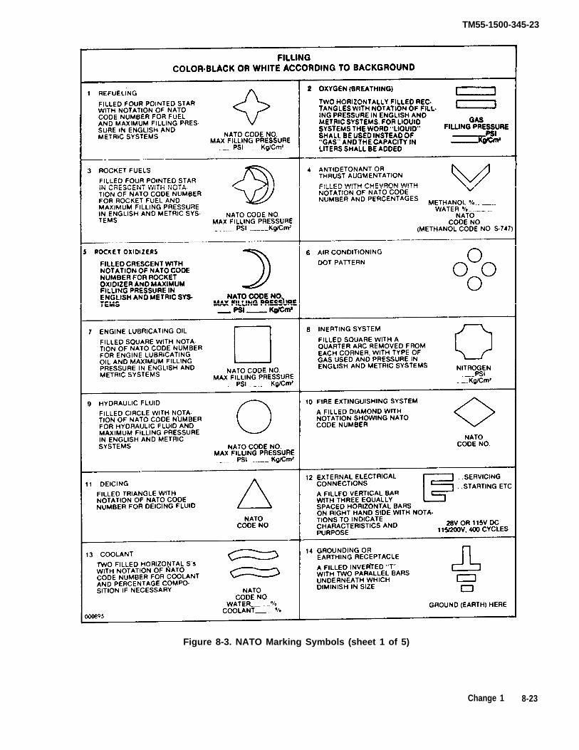
TM55-1500-345-23
Figure 8-3. NATO Marking Symbols (sheet 1 of 5)
Change 1 8-23

TM55-1500-345-23
Figure 8-3. NATO Marking Symbols (Sheet 2 of 5)
8-24 Chonge 1
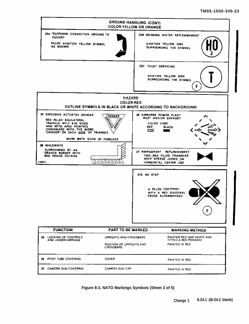
Figure 8-3. NATO Markings Symbols (Sheet 3 of 5)
Change 1 8.24.1 /(8-24.2 blank)
TM55-1500-345-23

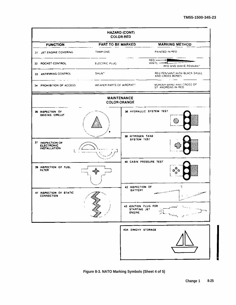
Change 1 8-25
Figure 8-3. NATO Marking Symbols (Sheet 4 of 5)
TM55-1500-345-23
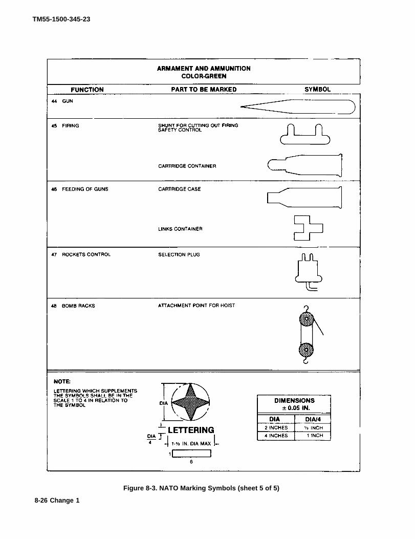
TM55-1500-345-23
Figure 8-3. NATO Marking Symbols (sheet 5 of 5)
8-26 Change 1

TM55-1500-345-23
Figure 8-4. Sidedraft Paint Booths
8-27

TM55-1500-345-23
Figure 8-5. Downdraft Paint Booths
8-28

TM55-1500-345-23
Figure 8-7. First Aid Kit
8-29


TM 55-1500-345-23
Figure 8-9. Optimum High Visibility Paint Scheme, Two Blades,Helicopter Tail Rotor Only
Page 8-32, Figure 8-10 DELETED
Change 9 8-31/(8-32 blank)

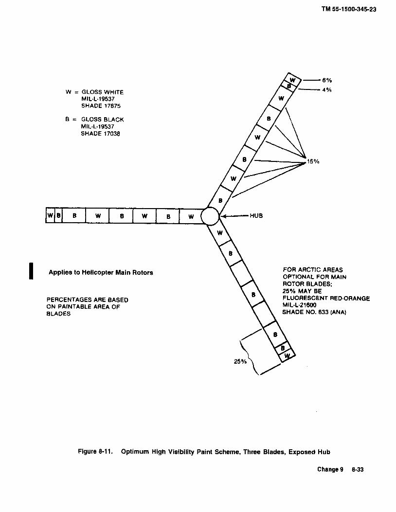

FIGURE 8-12. Optimum High Visibility Paint Scheme, Three Props, with Spinner.
FROM TIP 6 INCHES
TO BE WHITE
BLADE, TO BE BLACKREMAINDER OF PROPELLER
* SPINNER
6
W B
B
B
W
W
W
APPLIES TO PROPELLERS ONLY.
B = Flat Black P/N G2002 (MFG U.S. PAINT)
W = White P/N G-8022 (MFG U.S. PAINT)
*SPINNER SHALL BE PAINTED WHITE- UNLESS RECEIVEDUNPAINTED, IN WHICH CASE IT SHALL BE POLISHED.
TM 55-1500-345-23
8-34 Change 9

W = White P/N G-8022 (MFG U.S. PAINT)
B = Flat Black P/N G2002 (MFG U.S. PAINT)
Figure 8-13. Optimum High Visibility Paint Scheme, Four Props, with Spinner.
APPLIES TO PROPELLERS ONLY.
TO BE WHITE
REMAINDER OF PROPELLERBLADE, TO BE BLACK
6
6 INCHES FROM TIP
B
B
BW
W
* SPINNER
B
W
W
W
*SPINNER SHALL BE PAINTED WHITE- UNLESS RECEIVEDUNPAINTED, IN WHICH CASE IT SHALL BE POLISHED.
TM 55-1500-345-23
Change 9 8-35

TM55-1500-345-23
Figure 8-14. Optimum High Visibility Paint Scheme, Four Blades,Helicopter Tail Rotor Only
8-36

TM 55-1500-345-23
CHAPTER 9HELICOPTER ILLUSTRATIONS
SECTION I DELETED
Pages 9-2 through 9-12 and Figures 9-1 through 9-3have been deleted.
Change 12 9-1/(9-2 Blank)


TM 55-1500-345-23
SECTION II AH-64 ILLUSTRATIONS
1. MIL-DTL-64159 or MIL-DTL-53039, Aircraft Green (entire aircraft, except as noted).
2. MIL-DTL-64159 or MIL-DTL-53039 Aircraft Black.
3. MIL-DTL-64159 or MIL-DTL-53039, Dark Sand (entire aircraft or high conspicuous paint schemewhen authorized, desert operations only). See Paragraph 5-11.
4. MIL-DTL-64159 or MIL-DTL-53039 Aircraft White (entire aircraft or high conspicuous paint schemewhen authorized, arctic operations only). See Paragraph 5-11.
5. MIL-P-21600, Fluorescent Red-Orange. ANA #633 (training aircraft-high visibility, only whereauthorized).
Figure 9-4. Tactical Paint Scheme, AH-64
Change 12 9-13

TM55-1500-345-23
Figure 9-5. Exterior and Interior Markings, AH-64 (Sheet 1 of 19)
9-14C
hange6

TM55-1500.345.23
Change 6
9-15
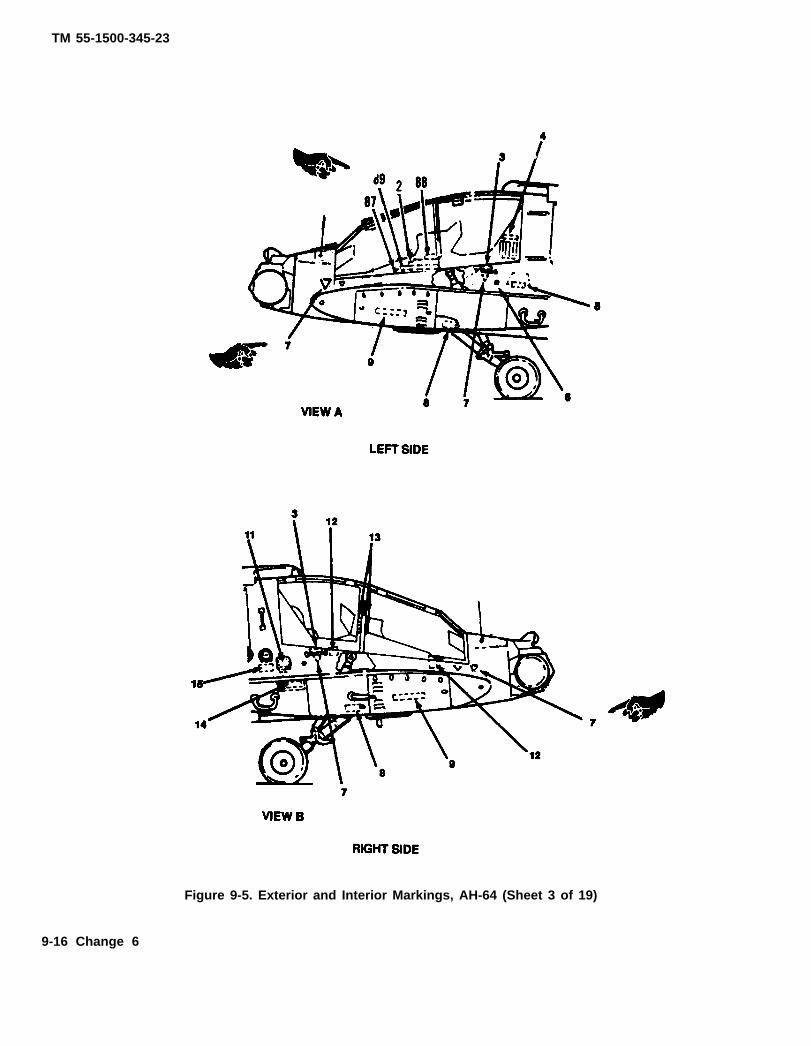
Figure 9-5. Exterior and Interior Markings, AH-64 (Sheet 3 of 19)
9-16 Change 6
TM 55-1500-345-23
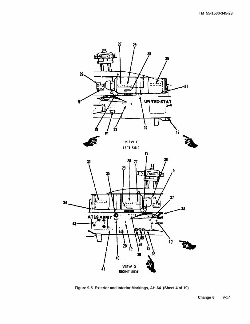
TM 55-1500-345-23
Figure 9-5. Exterior and Interior Markings, AH-64 (Sheet 4 of 19)
Change 6 9-17

TM55-1500-345-23
Figure 9-5. Extetior end Intetior Markings, AH-84 (Sheet 5 of 19)
9-18 Change 6

TM55-1500-345~239-19
Ch
an
ge
6

9-2
0
C
ha
ng
e
6
TM
55-1
500-
345-
23

TM55-1500-345-23
Figure 9-5, Exterior and Interior Markings, AH-64 (Sheet 8 of 19)
Change 6 9-21

TM 55-1500-345-23
Figure 9-5. Exterior and Interior Markings, AH-64 (Sheet 9 of 19)
9-22 Change 7

TM55-1500-345-23
Figure 9-6. Exterior and Interior Markings, AH-64 (Sheet 10 of 19)
Change 6 9-23

TM55-1500-345-23
Figure 9-5. Exterior and Interior Makings, AH-64 (Sheet 11 of 19)
9-24 Change 6

TM55-1500-345-23
CODENO. I DIRECTIONS
1 Deleted
2 LH side of canopy at FS 103.50. Locate belowsill and center for best fit with Codes 87 and 89.l-in. aircraft black letters.
3 1/2-in. aircratft black letters, 13 required.
4I
LH side of cannopy above louvers at FS 150.00,WL 157.20, l/2-m , aircraft black Ietters.
5 LH and RH side of fuselage on transmiss io naccess doors, LH side of fuselage at FS 160.00,WL 135.00, on fuselage lower surface at FS60.00, BL 0.00 and FS 75.00, BL 0.00, l/2-in.aircraft black letters.
6 Both sides of fuselage at FS 147.00, WL 135001/4-in. aircraft black letters.
7 Both sides of fuselage, 2 on each side at FS65.00 and FS 140.00 l/2-in. aircraft black lettersand triangle.
8 Both sides of fuselage on access door on ammochute fairing at FS 120.00, l/2-m . aircraft blackletters.
9 Both avionics bays centered on doors, l/2-in.aircraft black letters.
10 RH side of fuselage at ground service jacks, 2places, FS 249.830, WL 129.640 and FS189.470, WL 129.640. (See figure 7-12 fordimensions (MIL-C-83413/9-2).
11 RH side of fuselage above access panel at FS155.00, WL 136.00, 1/2-in. aircraft black letters.
WORDING
Us. ARMY AH-64AU.S. A SERIAL NO. 00000
NO STEP
EMERGENCY AIR INLET
CONTROLSACCESS
MOORING LUG ACCESS
AVONICS BAY
REFUEL CONTROL PANEL
Figure 9-5. Exterior and Interior Makings, AH-64 (Sheet 12 of 19)
Change 6 9-25

TM55-1500-345-23
CODElN o .
12
13
14
15
16
17
18
19
20
21
DIRECTIONS
RH side of fuselage at canopy handles, air-craft black.
Inside pilots’s cockpit, RH side, on fwd sideof CPG hold-open device, l/2-in. aircraftblack letters.
RH side of fuselage on access door on am-mo chute fairing at FS 155.00, l/2-in. aircraftblack letters.
RH side of fuselage at fwd fuel filler cap.l/2-in. aircraft black letters.
WORDING
NO HOLD
FIRE EXTINGUISHER INSIDE
Both sides of fuselage at FS 40.00 with ar-row pointing toward hatch on centerline, air-craft black.
1. Centered on BL0.000 on doghouse fakingassembly at FS 168.00 1/2-in, aircraft blackletters.2. Left of BL0.000, lower fuselage surface fwdof antenna at FS 468.00 1/2-in. aircraft blackletters.
See item 16 above
Both sides of fuselage on transmission accessdoor, 1/2-in. aircraft black letters.
RH side of fuselage, above aft fuel drain valveand below fwd fuel drain valve, l/2-in. aircraftblack letters.
Both sides aft FABs at FS 195.8& WL 123.65,I/2-in. aircraft black letters.
GRAVITY FUEL FILLERCAPACITY 155 U.S. GAL.
IFF TRANSPONDER
MAIN TRANSMISSIONOIL LEVEL SIGHT GAUGEINSIDE
FUEL SUMP DRAINCONTROL
INERTING SYSTEM VENT INSIDE
Figure 9-5. Exterior and Interior Markings, AH-64 (Sheet 13 of 19)
9-26 Change 6

TM55-1500-345-23
WORDINGCODENO. DIRECTIONS
Fwd fuselage lower surface on access hatchFS 65.00, l/2-in. aircraft black letters.
22
23
24
CYCLIC STICK ACCESS
Bottom of fuselage, fwd of jack pads, 3places; at FS 120.00(2 places) and FS 450.00(1 place). 1/2-in. aircraft black letters.
JACK PAD
RH side of fuselage below drain at FS312.00, WL 116.20, l/2-in. aircraft blackletters.
HVDRALIC OVERFOLWDRAIN
Fuselage lower surface on access panels atFS 170,00 and FS 255.00, l/2-in. aircraftblack letters.
FUEL DUMP VALVE25
26
27
LH side of fuselage on transmission accessdoor. l/2-in. aircraft black letters.
HYDRAULICRESERVOIR OIL LEVELSIGHT GAUGE INSIDE
ENGINE OIL LEVELSIGHT GAUGESERVICE ENGINE WITHMIL-L-23699 OR MIL-L-7808 OIL
Bottom aftside of firewall, both nacelles.l/2-in, aircraft black letters.
28 Both nacelles, interior surface of engine firedoors below hinges. Readable when door isopen. l/2-in. aircraft black letters.
WORK PLATFORMLOAD LIMIT400 POUNDS
29
30
31
32
33
34
Both nacelles on engine fire doors. l/2-in.aircraft black letters.
ENGINE FIRE DOORS
Both nacelles on engine exhaust fairing.l/2-in. aircraft black letters.
DANGER – ENGINE EXHAUST
Beside ECU exhaust outlet, LH side. 1/2.in.aircraft black letters.
DANGER – ECU EXHAUST
FIRE EXTINGUISHERDISCHARGE DISK
LH side of fuselage at FS 257.00 and WL148.50. l/2-in. aircraft black letters.
Both sides of fuselage near trailing edge ofwing. l/2-in. aircraft black letters.
CAUTION – DISCONNECT HYD.ELECTRICAL & PITOT CONNECTORSBEFORE REMOVING WING
Beside APU exhaust duct, RH side. 1/2-in.aircraft black letters.
DANGER – APU EXHAUST
Figure 9-5, Exterior and Interior Markings, AH-64 (Sheet 14 of 19)
Change 6 9-27
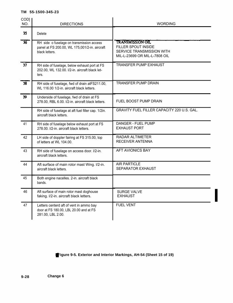
TM 55-1500-345-23
COD]NO.
41
42
43
44
45
46
47
9-28
DIRECTIONS
Delete
RH side o fuselage on transmission accesspanel at FS 200.00, WL 175,001/2-in. aircraftblack letters.
RH side of fuselage, below exhaust port at FS202.00, WL 132.00. l/2-in. aircraft black let-ters.
RH side of fuselage, fwd of drain atFS211.00,WL 116.00 1/2-in. aircraft black letters.
Underside of fuselage, fwd of drain at FS278.00, RBL 6.00. l/2-in. aircraft black letters.
RH side of fuselage at aft fuel filler cap. 1/2in.aircraft black letters.
RH side of fuselage below exhaust port at FS278.00. l/2-in. aircraft black letters.
LH side of doppler fairing at FS 315.00, topof letters at WL 104.00.
RH side of fuselage on access door. l/2-in.aircraft black letters.
Aft surface of main rotor mast Wing. l/2-in.aircraft bIack letters.
Both engine nacelles. 2-in. aircraft blackbands.
Aft surface of main rotor mast doghousefaking. l/2-in. aircraft black letters.
Letters centerd aft of vent in ammo baydoor at FS 180.00, LBL 20.00 and at FS281.00, LBL 2.00.
WORDING
FILLER SPOUT INSIDESERVICE TRANSMISSION WITHMIL-L-23699 OR MIL-L-7808 OIL
TRANSFER PUMP EXHAUST
TRANSFER PUMP DRAIN
FUEL BOOST PUMP DRAIN
GRAVITY FUEL FILLER CAPACITY 220 U.S. GAL.
DANGER - FUEL PUMPEXHAUST PORT
RADAR ALTIMETERRECEIVER ANTENNA
AFT AVIONICS BAY
AIR PARTICLESEPARATOR EXHAUST
SURGE VALVEEXHAUST
FUEL VENT
Figure 9-5. Exterior and Interior Markings, AH-54 (Sheet 15 of 19)
Change 6

TM55-1500-345-23
CODENO. DIRECTIONS WORDING
RADAR JAMMERRCVR ANTENNA
48 Top of doghouse fairing, LH side of antennahousing, FS 158.00. l/2-in. aircraft blackletters.
Bottom of RH nacelle, adjacent to sightgauge access door. 1/2-in. aircraft blackletters.
49 APU GEARRBOX OIL LEVELSIGHT GAUGESERVICE GEARBOX WITHMIL-L-23699 OR MIL-L.7608 OIL
ENGINE DRAINUnderside of both nacelles at FS 237.50, BL26.00. 1/2-in. aircraft black letters
50
51 Underside of RH nacelle at FS 273.40, BL26.85. 1/2-in. aircraft black letters.
Both wingtips adjacent to access door. 1/2-in. aircraft black letters.
Underside of RH nacelle at FS 250.75, BL26.50. l/2-in. aircraft black letters.
APU TURBINEPLENUM DRAIN
INTER-COMMRECEPTACLE
APU FUEL DRAIN
52
53
54 Underside of RH nacelle at FS 252.00, BL26.85. l/2-in. aircraft black letters.
Upper surface of both wings, on accesspanel at BL 28.00. 1/2-in. aircraft blackletters.
APU VENT
WING ACCESS55
Both ammo bay doors, centered at FS205.00, bottom of letters at W L 106.00, l/2-in.aircraft black letters.
AMMO BAY56
WATER WASHACCESS
GROUND AIR INPUT
VHF AM/FM NO. 2
57 Underside of both nacelles, on access panelat FS 225.00. 1/2-in. aircraft black letters.
Bottom of LH nacelle on access door. l/2-in.aircraft black letters.
Lower fuselage surface, centered aft ofblade antenna at FS 355.00. 1/2-in. aircraftblack letters.
58
59
60 Both sides of fuselage, most fwd letter (“U”left side, “Y” right side) at FS 271.00, tops ofletters at WL 137.50, aircraft black letters
UNITED STATES ARMY6 INCH HIGH 4 INCH WIDEDISTANCE BETWEEN LETTERS 1 INCH,DISTANCE BETWEEN WORDS 4 INCH.
Figure 9-5. Exterior and Interior Markings, AH-64 (Sheet 16 of 19)
Change 6 9-29
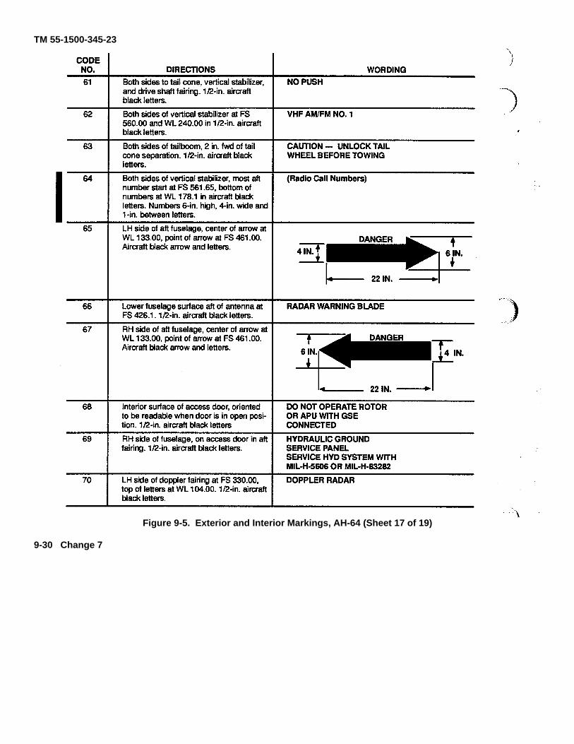
TM 55-1500-345-23
Figure 9-5. Exterior and Interior Markings, AH-64 (Sheet 17 of 19)
9-30 Change 7

TM 55-1500-345-23
CODENO. DIRECTIONS WORDING71 LH side of doppler fairing at FS 345.00, top
of letters WL 104.00. 1/2-in. aircraft blackletters.
RADAR ALTIMETERXMTR ANTENNA
72 RH side of fuselage aft of access door at FS344.00. 1/2-in. aircraft black letters.
EXTERNAL POWERCONNECTOR — 115VAC/DC3PH 400HZ
73 Both sides of aft fairing upper surface.1/2-in. aircraft black letters.
— DISCONNECT ELECTRICAL CON-NECTORS BEFORE REMOVING FAIR-ING
74 Lower fuselage surface aft on antennafairing at FS 355.00. 1/2-in. aircraft blackletters.
ADF LOOP ANTENNA
75 Lower fuselage surface aft on antennafairing at FS 355.00. 1/2-in. aircraft blackletters.
ADF SENSE ANTENNA
76 Lower fuselage surface aft on antennafairing at FS 355.00. 1/2-in. aircraft blackletters.
ADF AMPLIFIERIMPEDANCE MATCHING
77 Locate aft of drains at FS 133.36, LBL 1.60;FS 152.10, RBL 1.60; FS 245.47, RBL 1.60;FS 267.06, RBL 1.20. 1/2-in. aircraft blackletters, 4 places.
FUEL DRAIN
78 Lower fuselage surface aft of antenna bladeat FS 393.00. 1/2-in. aircraft black letters.
UHF/IFF TRANSPONDER
79 Locate on centerline of aircraft, top of noseat FS 39.00. 1/2-in. aircraft black letters andborder.
Figure 9-5. Exterior and Interior Markings, AH-64 (Sheet 18 of 20)
Change 12 9-30.1

TM 55-1500-345-23
CODENO. DIRECTIONS WORDING80 Marking on pilot and co-pilot/gunner
collective stick chop collar will have blackletters on orange-yellow background.
81 Forward upper corner of right hand ammochute fairing at approximately FS 115.00and WL 128.00. 1/2-in. aircraft black lettersand border.
Figure 9-5. Exterior and Interior Markings, AH-64 (Sheet 19 of 20)
9-30.2 Change 12

TM 55-1500-345-23
CODE NO. DIRECTIONS WORDING
82 RH underside at FS 87.00 adjacent toaccess door, 1/2-in. aircraft black letters.
UTILITY LIGHT & GROUNDPOWER RECEPTACLE
83 LH side and RH side of fuselage at WL114.87, FS 220.62 (one marking under bothdrains) 1/2-in. black letters.
TRANSMISSION DRAINS
84 On underside of both nacelles, outboard ofdrain LBL 26.50, FS 245.00 and RBL 26.50,FS 244.50. 1/2-in. aircraft black letters.
COMBUSTOR DRAIN
85 RH side of fuselage at WL 114.44, and FS223.65. 1/2-in. aircraft black letters.
AIR SEPARATOR DRAIN
86 On RH side of fuselage at WL 114.50, FS228.12. 1/2-in. aircraft black letters.
APU PUMP DRAIN
87 LH side of canopy at FS 103.00 below Code89, 1/4-in. aircraft black letters.
WP -Indicates wash primer used
P -Indicates primer used
L -Indicates lacquer used (if required)
C -Indicates coating used (if required)
88 LH side of canopy at FS 105.00 above Code2. 1/4-in. aircraft black letters.
NOTE
Date shown on stencil is date aircraftpainted with MIL-DTL-64159 or MIL-DTL-53039 paint.
89 On LH side of canopy at FS 103.50 belowCode 2. 1/2 in. aircraft black letters.
SERVICE THIS AIRCRAFT WITH MIL-T-83133GRADE JP8 AVIATION FUEL. IF NOT AVAILABLE,REFER TO TB 55-9150-200-24 FOR ALTERNATEFUEL.
90 On underside of LH and RH wing assembly,centered on WG STA 31.570 with arrowpointing inboard towards ground servicejack. Arrow tip should end 1-in from groundservice jack (BL 66.540). Aircraft blackletters.
91 LH and RH wings upper surface at FS228.00, BL 28.00. 1/2-in. aircraft blackletters.
AUX FUEL SYSTEM QUICK DISCONNECT
Figure 9-5. Exterior and Interior Markings, AH-64 (Sheet 20 of 20)
Change 12 9-31

TM 55-1500-345-23
Figure 9-6. Station Diagram, AH-64
9-32
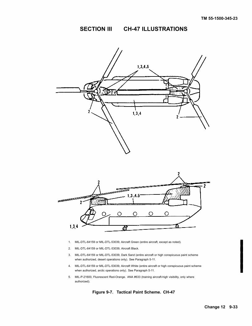
TM 55-1500-345-23
SECTION III CH-47 ILLUSTRATIONS
1. MIL-DTL-64159 or MIL-DTL-53039, Aircraft Green (entire aircraft, except as noted).
2. MIL-DTL-64159 or MIL-DTL-53039, Aircraft Black.
3. MIL-DTL-64159 or MIL-DTL-53039, Dark Sand (entire aircraft or high conspicuous paint schemewhen authorized, desert operations only). See Paragraph 5-11.
4. MIL-DTL-64159 or MIL-DTL-53039, Aircraft White (entire aircraft or high conspicuous paint schemewhen authorized, arctic operations only). See Paragraph 5-11.
5. MIL-P-21600, Fluorescent Red-Orange. ANA #633 (training aircraft-high visibility, only whereauthorized).
Figure 9-7. Tactical Paint Scheme. CH-47
Change 12 9-33
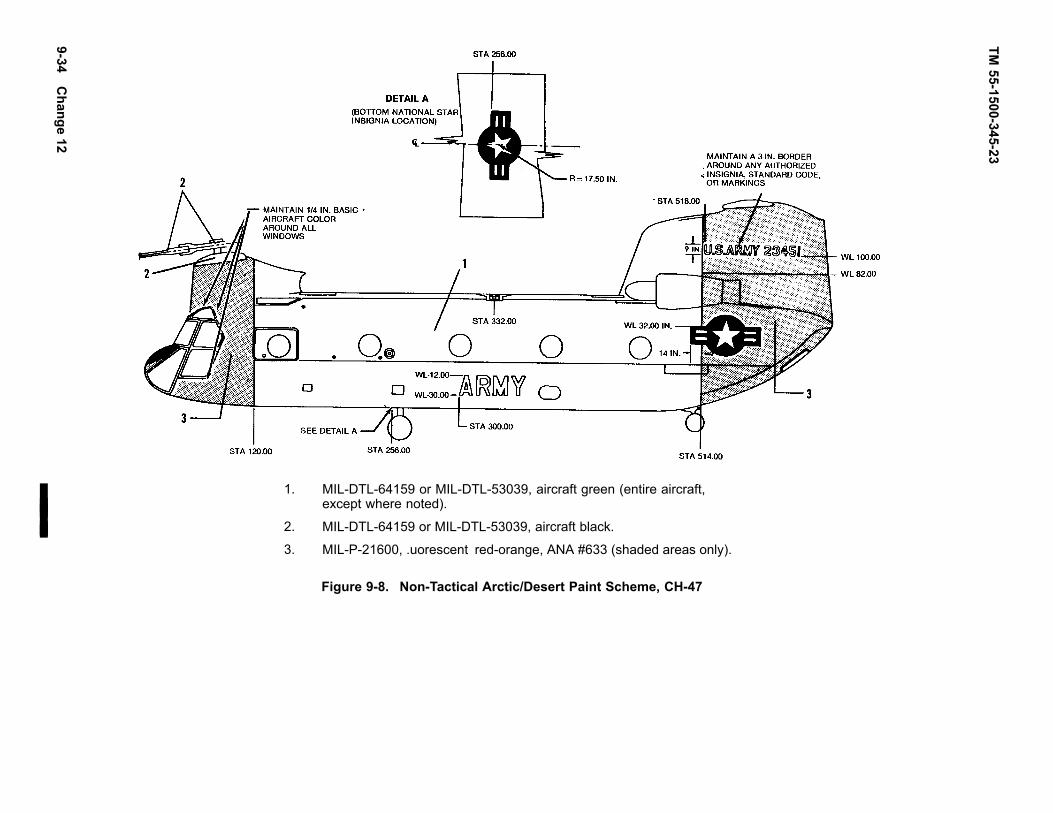
TM55-1500-345-23
1. MIL-DTL-64159 or MIL-DTL-53039, aircraft green (entire aircraft,except where noted).
2. MIL-DTL-64159 or MIL-DTL-53039, aircraft black.
3. MIL-P-21600, .uorescent red-orange, ANA #633 (shaded areas only).
Figure 9-8. Non-Tactical Arctic/Desert Paint Scheme, CH-47
9-34C
hange12

TM55-1500-345-23
9-35

9-36
TM
55
-15
00
-34
5-2
3
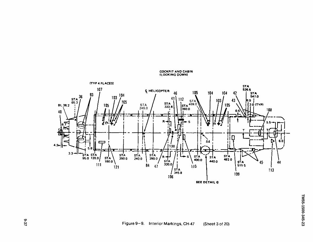
TM55-1500-345-23
9-37
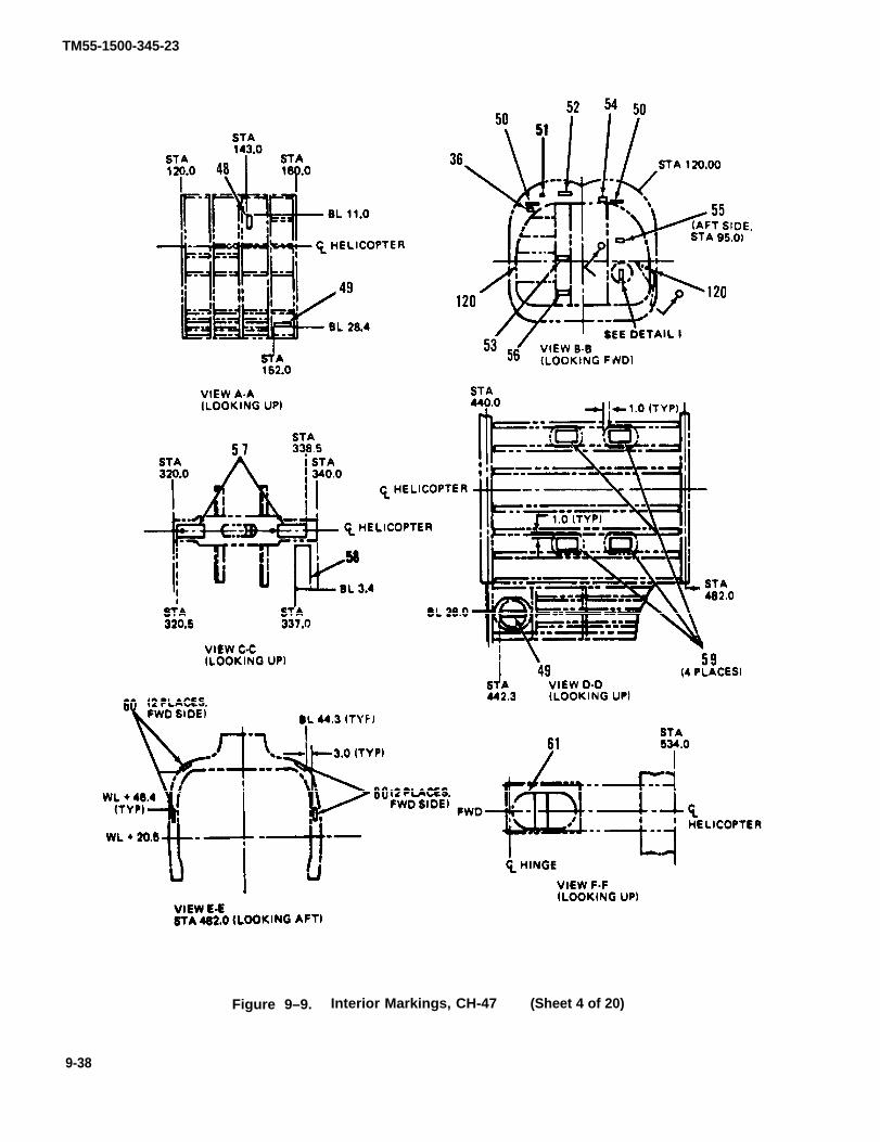
TM55-1500-345-23
Figure 9–9. Interior Markings, CH-47 (Sheet 4 of 20)
9-38
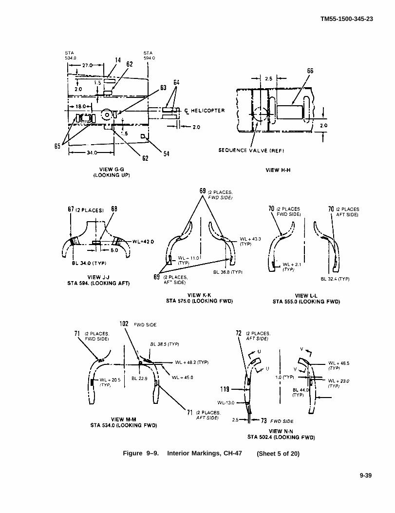
TM55-1500-345-23
Figure 9–9. Interior Markings, CH-47 (Sheet 5 of 20)
9-39

TM55-1500-345-23
Figure 9–9. Interior Markings, CH-47 (Sheet 6 of 20)
9-40

TM55-1500-345-23
Figure 9–9. Interior Markings, CH-47 (Sheet 7 of 20)
9-41

TM55-1500-345-23
Figure 9–9. Interior Markings, CH-47 (Sheet 8 of 20)
9-42

TM 55-1500-345-23
CODENO. DIRECTIONS WORDING
1 Left side of fuselage at station 106.5, WL 32.5.3 in.MIL-DTL-64159 or MIL-DTL-53039, aircraft white,No. 37875, circle with 1-in. MIL-DTL-64159 orMIL-DTL-53039, aircraft red, No. 31136, cross.
2 Left side of fuselage at station 106.5, WL 45.2.1/2-in. white letters.
NO 2 CONTROLSYSTEM FILTER
3 Right side, sta 157, above door 1/2-in. whiteletters.
LEVELING BRACKET
4 Both sides, station 163.5, WL 27.6. 1-in. whiteletters.
MAX CONCENTRATED FLOOR LOADING FWDOF STA 160.0 NOT TO EXCEED 1000 LBSCONCENTRATED LOAD.
5 Both sides of fuselage centered on station 181,303, 425 at WL 35.0.3 in. MIL-DTL-64159 orMIL-DTL-53039, aircraft black, No. 37038 andMIL-DTL-64159 or MIL-DTL-53039, aircraft white,No. 37875. See Detail J for type.
6 Both sides of fuselage. Station 249 and 348 at WL8.0 1-in white letters.
UT RECP
7 Both sides of fuselage at station 249 and 348 atWL 6.0 1/2-in white letters.
28VDCAMPS: 1 = 15A 2 = 7.5A 3 = 5A
8 Both sides of fuselage at station 317. WL 44.9.1/2’ white letters.
115V, 3PH, 400CY, 15AMP
8 CH-47D, both sides of fuselage at station 317, WL44.9, 1/2-in. white letters.
115V, 1PH, 15AMP115V, 3PH, 15AMP
9 Both sides of fuselage at station 317.0, WL 41.9.1’ white letters.
MISSILE HEAT PLUG
9 CH-47D, both sides of fuselage at station 317.0,WL 41.9, 1-in white letters.
400 CYCLE AC UTILITY RECEPTACLE
10 Right side of fuselage at station 335.0, WL 23.9.1-in. white letters
HOIST OPER STATION
11 Arrow white 1/2-in. X 3 in. See Detail C, E and F.
12 Right side of fuselage. Station 363.3, WL 37.1.1-in. white letters.
HOIST OPER ATTACH.
13 Right side of fuselage at station 506, WL 36.0.1/2-in. white letters.
RAMP MANUAL OVERRIDE
Figure 9-9. Interior Markings, CH-47 (Sheet 9 of 20)
Change 12 9-43

TM 55-1500-345-23
CODENO. DIRECTIONS WORDING
14 See View G-G, and Detail C, station 549.3, WL53.0; station 538.8 WL 8.5. 1/2" white letters
NOTE
5 req’d on S/N 59-4983 thru 66-19028. 4req’d on S/N 66-19029 and subsequent.
ACCUMULATOR CHARGE1400 PSI—AIR OR NITROGEN
15 Station 525, WL 22.5. Right side of fuselage.Finish half of .ller cap, orange; the other halfMIL-DTL-64159 or MIL-DTL-53039, aircraft grayinterior, No. 36231
FILLERUTILITY TANK
16 Right side of fuselage, station 550, WL 33.5. 1/2"white letters. Eff. on CH-47 S/N 65-7978 andsubsequent.
UTILITY RETURN FILTER
17 Right side of fuselage, station 538.8, WL 8.5. 1/2"white letters.
INITIAL 1800 PSI CHARGEREQ’D FOR -65°F OPERATION
18 Right side of fuselage, station 517.5, WL 36. 1/2in. white letters.
UTILITY PRESSURE FILTER
19 Both sides of fuselage. Two places, station 220,391 and 460. WL-21.5. 1" white letters. Arrow is 1"X 3". 3 places on heater dust on each side.
20 Both sides of fuselage. Centered on station 425.WL -21.5. 1/2" white letters. Eff on S/N 64-13117thru 65-7977. S/N 56-7978 and subsequent.
CARGO ESTA 425 CAP 15250 LBS.CAP 22875 LBS.
21 Both sides of fuselage, station 160, 225 and 438.WL -21.5. 1" white letters.
ALL TIE DOWN RINGS500 LBS UNLESS NOTED
21 CH-47D, Both sides of fuselage, station 160, 225,and 438, WL -21.5, 1" white letters.
ALL TIE DOWN RINGS5000 LBS UNLESS NOTED
22 Both sides of fuselage. Station 306.8 WL -21.5White letters.Eff S/N 64-13117 thru 65-7977. S/N 65-7978 andsubsequent.
CARGO DSTA 303CAP 15250 LBS.*CAP 22875 LBS.
23 Both sides of fuselage at 14 places at heateroutlets. 1st line 1" letters. Remainder 1/2" letters(white).
24 Right side of fuselgae on beam. BL 18 beam 1"white letters
TO STOW SEAT-FOLD BACK FWD& SECURE WITH STRAP — FOLDDOWN SEAT
Figure 9-9. Interior Markings, CH-47 (Sheet 10 of 20)
9-44 Change 12
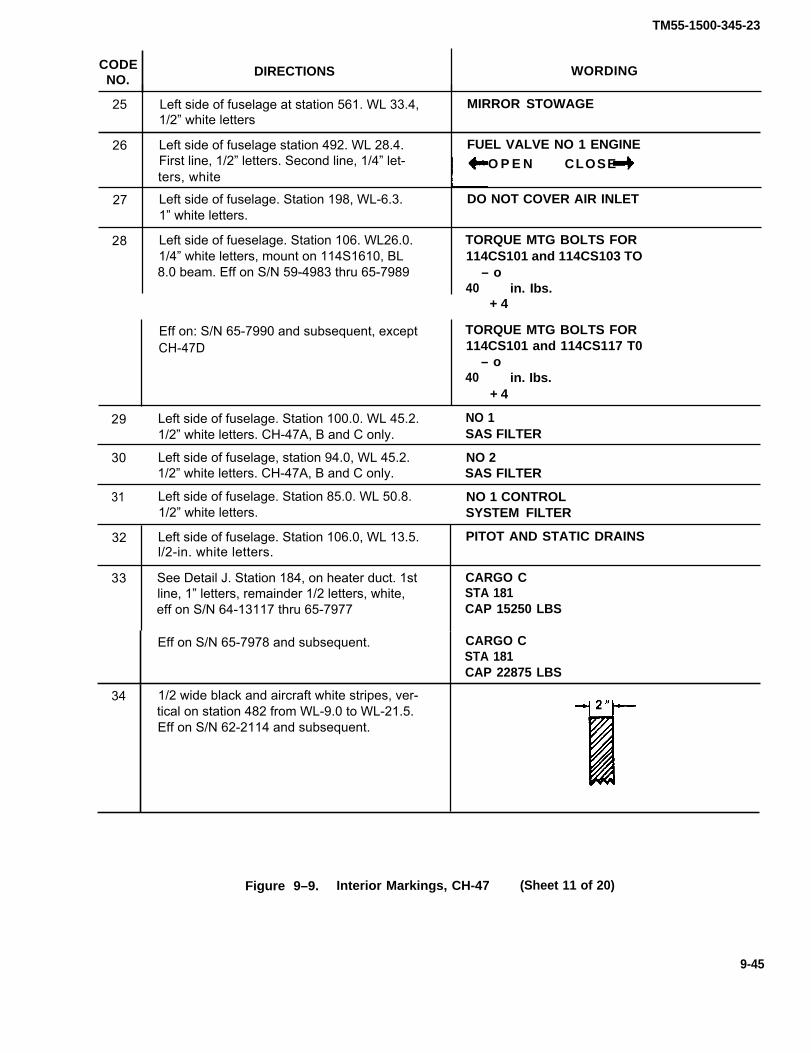
TM55-1500-345-23
CODENO.
DIRECTIONS WORDING
25 Left side of fuselage at station 561. WL 33.4, MIRROR STOWAGE1/2” white letters
26 Left side of fuselage station 492. WL 28.4. FUEL VALVE NO 1 ENGINEFirst line, 1/2” letters. Second line, 1/4” let- O P E N CLOSE ters, white
27 Left side of fuselage. Station 198, WL-6.3. DO NOT COVER AIR INLET1” white letters.
28 Left side of fueselage. Station 106. WL26.0. TORQUE MTG BOLTS FOR1/4” white letters, mount on 114S1610, BL 114CS101 and 114CS103 TO8.0 beam. Eff on S/N 59-4983 thru 65-7989 – o
40 in. Ibs.+ 4
Eff on: S/N 65-7990 and subsequent, except TORQUE MTG BOLTS FORCH-47D 114CS101 and 114CS117 T0
– o40 in. Ibs.
+ 4
29 Left side of fuselage. Station 100.0. WL 45.2. NO 11/2” white letters. CH-47A, B and C only. SAS FILTER
30 Left side of fuselage, station 94.0, WL 45.2. NO 21/2” white letters. CH-47A, B and C only. SAS FILTER
31 Left side of fuselage. Station 85.0. WL 50.8. NO 1 CONTROL1/2” white letters. SYSTEM FILTER
32 Left side of fuselage. Station 106.0, WL 13.5. PITOT AND STATIC DRAINSl/2-in. white letters.
33 See Detail J. Station 184, on heater duct. 1st CARGO Cline, 1” letters, remainder 1/2 letters, white, STA 181eff on S/N 64-13117 thru 65-7977 CAP 15250 LBS
Eff on S/N 65-7978 and subsequent. CARGO CSTA 181CAP 22875 LBS
34 1/2 wide black and aircraft white stripes, ver-tical on station 482 from WL-9.0 to WL-21.5.Eff on S/N 62-2114 and subsequent.
Figure 9–9. Interior Markings, CH-47 (Sheet 11 of 20)
9-45

TM55-1500-345-23
CODENO.
DIRECTIONS WORDING
35 Left side of fuselage centered on station 486and WL-2.0.1” white letters.
3 places in fuslage. 1” black letters onorange-yellow background. Station 492, WL-6.5, BL37.0, WL38.7, View B—B.
STA 486
36 FIRE EXIT
37 Left side of fuselage, station 537, WL + 3.5.1/2” white letters. Eff on S/N 59-4982 thru65-7977
J–2 COMPASS FLUX VALVE
COMPASS FLUX VALVEEff on S/N 65-7978 and subsequent
Left side of fuselage, station 537, WL 22.2.1st two lines 1/2”, last line 1/4” white.
EMERGENCY APU FLUID SHUTOFF38
Left side of fuselage, station 334.0, WL-12.0.1” white letters.
39 CRANK STOWAGE –RESCUE HATCH &RAMP MECH.
40 Centered on door, 1/2” white letters ACCESS- PITOT AN D STATICDRAIN LINES
41 On floor, station 340 approx. Arrow 1/2” X3.50 aircraft white on black, see View S-S.
Right side, sta 526, 1/2” white letters.42 FILLING
43 Right side, sta 526, 1/2” white letters. NORMAL
Centered on rear door, first line 1”, re-mainder 1/2” orange-yellow, refer to ViewU—U and Detail H.
Fig 8, Detail G, 1” white letters L.H. and R.H.side, station 173.3, 220.5, 265.5, 302.5, 342.3,381.5, 420.3, and 442.3.
On lower door, station 345, 1” aircraft whiteletters.
EMERGENCY EXITPULL STRAP OUT – PUSH PANEL
44
45 W.L.O
TURN LATCH TO UNLOCK & LOCKOUTER HATCH-CAUTION-UNLOCKBEFORE TURNING CRANK TO OPENHATCH
46
47 On lower door, station 322.1” aircraft whiteletters and arrow.
UNLOCK
Figure 9–9. Interior Markings, CH-47 (Sheet 12 of 20)
9-46

TM 55-1500-345-23
CODENO. DIRECTIONS WORDING
48 View A—A, looking up, station 143 BL 11.0. 1/2"white letters.
STATIC LINE DRAIN
49 View A—A and D—D (looking up), station 152 and442. 1/2" white letters.
CRANE ACCESS
50 View B—B, 1" white letters, sta 120.0, BL 38, WL40.5, BL 28 WL 43.0.
STA 120.0
51 View B—B, 1/4" white letters, BL 25, WL 49.0. TROOP WARNING SYSTEM
52 View B—B, 1/2" white letters, BL 15.5, WL 48.0. RESCUE PULLEY ATTACH
53 View B—B 1" white letters station 120, BL 17, WL3.9
LITTER POLE STORAGE
54 View B—B. 1" white letters sta 120, BL 12.0 WL45.0. Eff on quantity of 1 ea S/N 65-7966-65-7977,Quantity of 2 ea, S/N 65-7978 and sub. Alsostation 594 (see View G—G).
ANCHOR LINE ATTACH.
55 View B—B, 1/4" white letters, station 95. BL 29.0,WL 15.5
CABIN LIGHT RELAYSRED WHITE
56 View B—B, 1" white letters Sta 120, BL 17.2, WL-20.
WINCH CABLE STOWAGE
57 View C—C (looking up). Center of helicopter,station 320 and 338. 1/4" white letters.
RESCUE CABLE CUTTERPULLEY ATTACH
58 View C—C (looking up), BL 8.4, station 337.0. 1/2"white letters.
CABLE CUTTERPLUG
59 View D—D (looking up), 1/2" white letters, 4 places. ACCESSMIX BOXMOUNTING BOLTS
60 View E—E, 1" white letters, 4 places. STA 482.0
61 View F—F (looking up), 1/2" white top center offuselage, fwd of sta 534 on door.
ACCESS-SYNCH SHAFTTHOMAS CPLG.
62 View G—G (looking up). 1/2" white letters. 2places.
ACCESS XMSNUNLATCH DROP PANEL
63 View G—G (looking up). 1/2" white letters. ACCESS — MAG PLUG
Figure 9-9. Interior Markings, CH-47 (Sheet 13 of 20)
9-47

TM 55-1500-345-23
CODENO. DIRECTIONS WORDING
64 View G—G (looking up). 1" white letters, 2 placesto be read from either side.
NO HANDHOLD
65 View G—G (looking up). 1/2" white letters, 2places.
XMSN OIL LEVEL SIGHTGAGE VIEW PLATE
66 View H—H, 1/2" black letters. SEQUENCE VALVE
67 View J—J, 1" white letters, station 594.0, left andright side.
STA 594.0
68 View J—J, 1" orange-yellow letters.
69 View K—K, 1" white letters, 4 places. STA 575.0
70 View L—L, 1" white letters, 4 places. STA 554.0
71 View M—M, 1" white letters, 4 places. STA 534.0
72 View N—N, 1" white letters, 4 places. STA 502.4
73 View N—N, 1/2" white letters.
74 View P—P, 1" white letters, 4 places. STA 200.0
75 View P—P, 1" white letters, 4 places. STA 240.0
76 View P—P, 1" white letters, 4 places. STA 280.0
77 View P—P, 1" white letters, 4 places. STA 320.1
78 View P—P, 1" white letters, 4 places. STA 360.0
79 View P—P, 1" white letters, 4 places. STA 400.0
80 View P—P, 1" white letters, 4 places. STA 440.0
81 View P—P, 1" white letters, 3 places. STA 160.0
82 View Q—Q, 1" white letter stencil to be readablefrom centerline A/C with door closed. Mount tounder surface of step.
83 View R—R, 1" black letters. Center hook. CARGO HOOK CAP16000 LB. (CH-47A)CARGO HOOK CAP20000 LB.(CH-47B/C)CARGO HOOK CAP26000 LB. (CH-47D)
Figure 9-9. Interior Markings, CH-47 (Sheet 14 of 20)
9-48 Change 12

TM 55-1500-345-23
CODENO. DIRECTIONS WORDING
84 1 in. black letters. CARGO HOOK CAP20000 LB (CH-47D)
85 View S—S, 1" black letters. HOOK STOWAGE STRAP
86 View T—T (ref Fig 9-9 (Sheet 6 of 20). 1/2" whiteletters. (Stencil to be readable when rotated intowork platform position).
MAX. WEIGHT 200 LBSON WORK PLATFORM
87 View V—V, .rst line, 1/2" white, second line, 1/4"white, station 502.4
88 Detail A, first line 1" orange-yellow, second line 1/2orange-yellow with arrow, 1/2" x 2-1/2" on blackhandles in cockpit. See arrow position in Detail A.For information on marking pilot and co-pilot doors,see paragraph 7-24.
89 Detail B, 1" orange-yellow letters, left side betweenstation 280 and 320. Right side between station360 and 400 place stencil on sides of window asshown. Refer to paragraph 7-22.
NOTE
Items 89 and 90 Eff on S/N 59-4983 thru66-097.
90 Detail B, cut out corners, 1" X 3" aircraft white asshown in item 89.
91 Detail C, Station 493, WL 28.4, first line 1/2"second line 1/4" white letters.
92 Detail C, Station 505, WL 19.6, first line 1/2"second line 1/4" white letters.
93 Two places aft of station 95, 1" white letters.Stencil to be readable from centerline of acft.
ACCESS PANELS — HYDRAULICLINES, TRANSFORMERS
Figure 9-9. Interior Markings, CH-47 (Sheet 15 of 20)
Change 12 9-49

TM 55-1500-345-23
CODENO. DIRECTIONS WORDING
94 Detail C, 1/2" black letters, station 491. Top line onone stringer bottom line on lower stringer at WL 0.
UP STOP DN
RAMP CONTROL
95 Detail C, 1" black, station 486, WL -2.0. Arrow 1/2"X 3".
96 Detail D, 1/2" orange-yellow letters. Refer toparagraph 7-22.
EMERGENCY EXITPULL STRAP OUTPUSH PANEL
97 Detail E, 1" white letters with arrow. Arrow locatedon Station 242.
98 Detail F, 1" white letters. Arrow located on station364.
STA. 364.0
99 Detail H, 1" white letters. Right side at fwd door. TURN HANDLE UPLIFT DOOR
100 Detail I, View B—B, aft side, station 95.0, 1/4"white letters.
CABLE CUTTER
101 Detail I, and View B—B, aft side, station 95.0, 1/4"white letters.
HOIST CONTROL
102 View M—M, 1/2" white fwd side, station 534. HYDRAULIC RES. GAGE
103 Aircraft white letters, 1/2", station 440, BL 26 andstation 165.
LOCATION FORMAINT CRANEBASE PLATE
104 Aircraft white dot, 1" station 138.5, 166.5, 427 and455, BL 26.
105 Black corner markings, 1" X 3" station 133.86,174.36, 424.25 and 464.75 BL 34.44 and BL 19.94,8 places.
Figure 9-9. Interior Markings, CH-47 (Sheet 16 of 20)
9-50

TM55-1500-345-23
CODENO.
DIRECTIONS WORDING
106 Orange-yellow letters, 1” station 348, center ALTERNATE GROUNDof A/C floor. To be read facing fwd of acft on EMERGENCY ESCAPEupper door. LIFT
107 Stripe 1” wide across cabin floor at station120, 242, 364, and 486. Stripe to be aircraftwhite
108 Center floor on ramp, 1” white letters. MAX WEIGHT 200 LBS.ON WORK PLATFORM
109 White 1/2” letters, station 500 on floor. LIFT PLUG FOR MANUALCARGO DOOR CRANKING
OPEN
110 Aircraft white 1” letters, fwd edge of stencil CRANK HERE TO OPENon station 360, OB edge of stencil on BL AND CLOSE OUTER HATCH17.25.
OPEN
111 White 1/2” letter, station 132.5, BL 24.5, top RESCUE PULLEY ATTACHof letters facing outboard.
112 Non-skid material on floor. Material requiredis MIL-W-5044. Type II aft of sta 120 andType I fwd of sta 120. Refer to paragraph3—11.
113 At rear emer. exit, 1” black letters on 15”Orange-yellow arrow. Pointing toward han-dle. Eff on S/N 66-, 118 and subsequent.Refer to paragragh 7-22.
114 Right side station 516, WL 53. 1/2” white let-ters.
BRAKE RETURNLINE FILTER
Eff on S/N 65-7978 and subsequent. I
115 White 1/2” letters, station 525, WL 53 and WARNING FILTER MAINTENANCEstation 554, WL 29.5, eff on: Qty of 1- S/N REQUIRED WHEN RED65-7978 thru 65-7994, Qty of 2-S/N 65-7995 & INDICATOR IS EXTENDED.
sub.
Figure 9-9. Interior Markings, CH-47 (Sheet 17 of 20)
9-51

TM55-1500345-23
CODENO.
DIRECTIONS
116 White 1/2” letters, station 95, WL 21 above114S1655 back-up panel. Eff on S/N 65-7990& sub.
117 First line, 1/2”, lower line 1/8” white, loca-tion, station 116, WL 12.0, adjacent to flowregulator. L. S., eff on S/N 65-1995 & sub.
118
119
120
Typical for 8 windows. Both sides at station220, 300, 380, 460, first line 1” letters, re-mainder 1/2” orange-yellow or reflective let-ters. 1/2” x 1” orange-yellow stripe aroundwindow at 6 places (positions 12, 2, 4, 6,8,and 10 o’clock). Eff on S/N 66-098 and subse-quent. Refer to paragraphs 7-19 thru 7-22.
View N–N, both sides at station 502.33, WL19.0, black letters 1/8” (metal-cal) eff on S/N66-19059 and subsequent.
View B—B, 5“ white letters, station 120center of mounting holes.Eff on S/N 65-8014 and subsequent.
S/N 66-118 and subsequent
121 A two (2”) wide lusterless aircraft whitestripe across the floor. Centered on station160.
122 Above the fire axe on right side on theupholstery at station 200, black 1” letters onan aircraft white rectangle.
123 CH-47D, 3/8” white letters, station 522.5, WL+35.5
124 CH-47D, Left side of fuselage, 1/2” white let-ters, station 553.5, WL+8.0
125 CH-47D, left side of fuselage, 1/2” white ar-row, station 492, WL+16.0
WORDING
WARNINGINSTALL BACK-UPPANEL BEFORE FLIGHT
FLOW REGULATORS
REGULATED FLOW DIRECTION
EMERGENCY EXITPULL STRAP OUTPUSH WINDOW OUT
FUEL VALVEWARNING LIGHT
XM 24 GUN MTG
XM 2 4 /’GUN MTG
FIRE AXE
APU CONTROL BOX
INTERPHONEWALKING CORDSTOWAGE
Figure 9-9. Interior Markings, CH-47 (Sheet 18 of 20)
9-52

TM 55-1500-345-23
CODENO. DIRECTIONS WORDING126 CH-47D, 1" white letters, 8 required ALL TIEDOWN RINGS
5000 LB UNLESS NOTED127 CH-47D left side of fuselage, 1/2" white letters,
station 206.0, WL +40N1 CONT ENG 1
128 CH-47D right side of fuselage, 1/2" white letters,station 206.0, WL +40
N1 CONT ENG 2
129 CH-47D right side of fuselage, 1/2" white letters,station 585.0, WL +48.5
APU START MDL
130 CH-47D right side of fuselage, 1/2" white letters,station 560.0, WL +30.5
131 CH-47D right side of fuselage, 1/4" white lettersand arrow, station 538.0, WL +41.5
132 CH-47D right side of fuselage, 1/4" white letters,station 538.0, WL +38.0
At temps below minus 25°F prechargeaccumulator 2050 psi with air or nitrogen.Accumulator will bottom at 3350 psi.
133 CH-47D right side of fuselage, white letters, station538.0, WL +34.5
134 CH-47D right side of fuselage, white letters, and1/2" arrow, station 515.5, WL +16.0
135 CH-47D right side of fuselage, 1/2" white letters,station 515.5, WL +14.5
136 CH-47D right side of fuselage, 3/8" white letters,station 517.0, WL +7.5
Figure 9-9. Interior Markings, CH-47 (Sheet 19 of 20)
Change 1 9-53

TM 55-1500-345-23
CODENO. DIRECTIONS WORDING
137 CH-47D, right side of fuselage, 1/2" white letters,station 523.0, WL +7.5
HYDR SYS FILL . . .
138 CH-47D, center of f oor, 3/8" white letters andarrow, station 330.0
139 On inside of aft transmission servicing access door.1/4-in. aircraft black letters.
MIL-L-7808 — CAP. 27QUARTS, SUMP — 9 QUARTSYSTEM. RUN FOR3 MINUTES, SHUT DOWN — REFILLTO FULL MARK ON XMSN CASE
Figure 9-9. Interior Markings, CH-47 (Sheet 20 of 20)
9-54 Change 11

TM 55
Chan
Figure 9-10. Exterior Markings, CH-47 (Sheet 1 of 29)
5-1500-345-23
nge 12 9-55

TM 55-1500-345
9-56 Change 5-23
e 12
Figure 9-10. Exterior Markings, CH-47 (Sheet 2 of 29)

Chan
TM 55nge 12 9-57
5-1500-345-23Figure 9-10. Exterior Markings, CH-47 (Sheet 3 of 29)
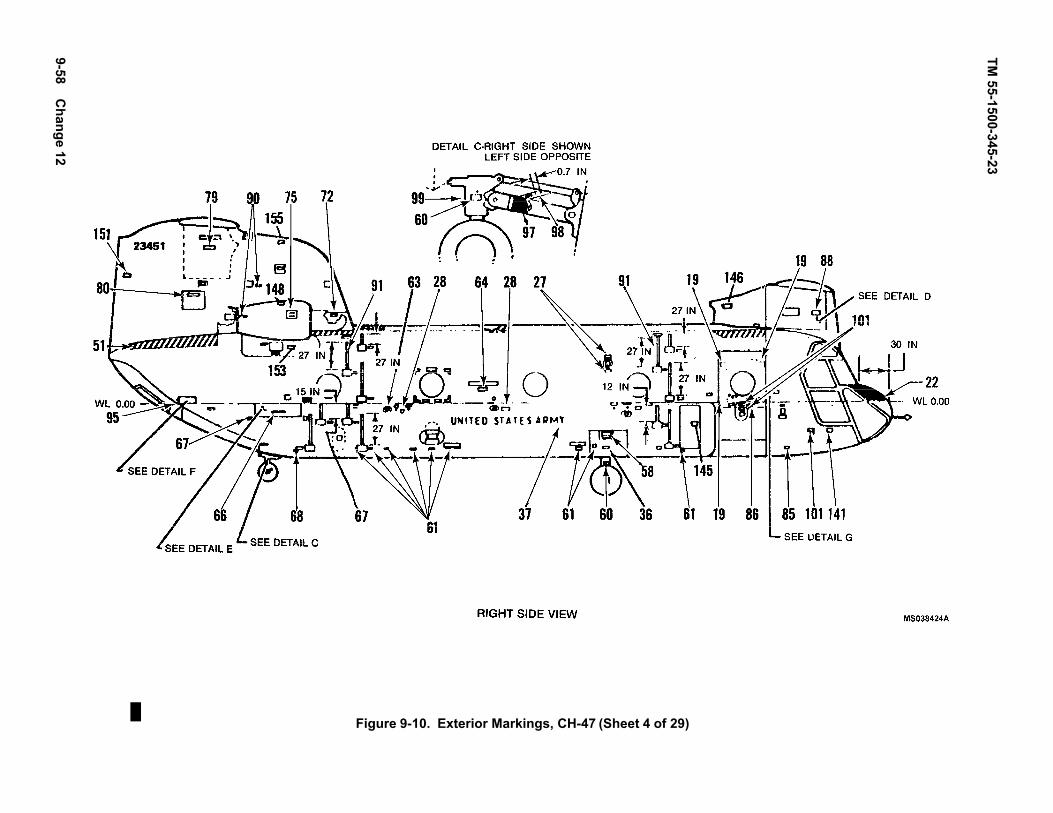
TM 55-1500-345
9-58 Change 5-23
12
Figure 9-10. Exterior Markings, CH-47 (Sheet 4 of 29)

TM55-1500-345-239-59
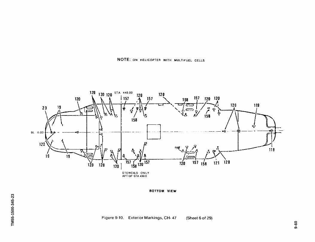
TM55
-150
0-34
5-23
9-60

TM55-1500-345-23
Figure 9-10. Exterior Markings, CH-47 (Sheet 7 of 29)
9-61

TM55-1500-345-23
9-62

TM55-1500-345-23
Figure 9-10. Exterior Markings, CH-47 (Sheet 9 of 29)
9-63

TM55-1500-345-23
Figure 9-10. Exterior Markings, CH-47 (Sheet 10 of 29)
9-64
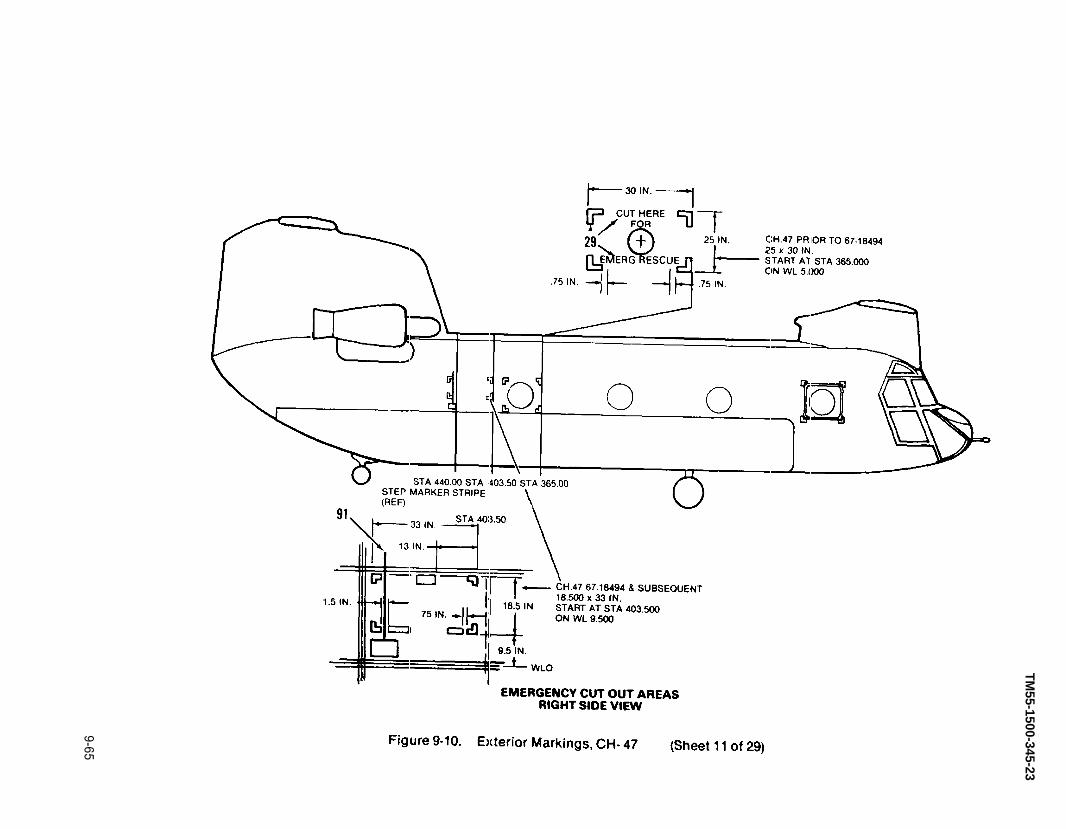
TM55-1500-345-23
9-65
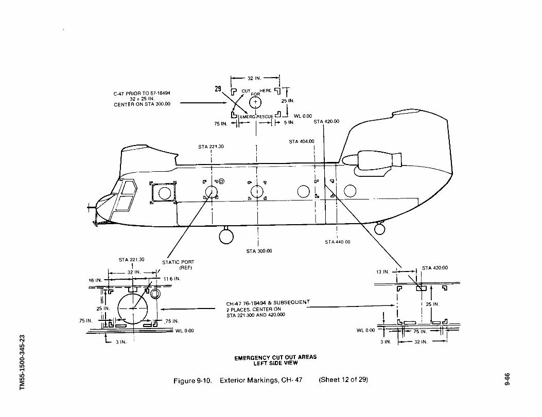
TM55
-150
0-34
5-23
9-66

TM 55-1500-345-23
1. Unless otherwise noted, all lettering is to be 1-in.
2. A standard size arrow will be used, when required, in the followingstencil.
CODENO. DIRECTIONS WORDING
1. Fixed portion of cowl between nacelle andvertical .n. Bottom of letters facing fwd.Also top of engine nacelle facing outbd.MIL-DTL-64159 or MIL-DTL-53039 aircraftblack, No. 37038
NO STEP
2 DELETE
3 Used with each set of steps, both sides offuselage. Also, above handgrip, top and sideof rear pylon, both sides, aircraft black.
HAND HOLD
4 Adjacent to access doors. To be read fromwalkway, aircraft black.
INSTALL COVERBEFORE FLIGHT
5 Paint a black ground symbol, shade 37038,dimensions per MIL-C-83413/9-2. Remove theoutside circle at sta 206 & 246 left fuselage.(Due to Emergency cut-out).
Figure 9-10. Exterior Markings, CH-47 (Sheet 13 of 29)
Change 12 9-67

TM 55-1500-345-23
CODENO. DIRECTIONS WORDING
6 Both sides of fuselage, 1/2-in. aircraft black letters. FUEL VENT
NOTE
CH-47, serial No. 68-15812 and subse-quent, sta 330. CH-47, serial No. 6718494thru 68-15811, sta 245 and 386. CH-47, se-rial No. 66-19098 thru 67-18493, sta 231and 395. CH-47, serial No. 67-18594 andsubsequent, sta 189, 243, 387, and 442.CH-47D, both sides of fuselage, sta 242,378, 443, WL +.5.
7 Right side top of fuselage, 2 in. below walkway,positioned between bulkheads (rivet line) betweensta 179.5 and sta 400. 1-in. aircraft black letters tobe read from walkway.
NO STEP
8 Both sides of fuselage adjacent to step *STEP
NOTE
On CH-47B, serial No. 66-19098, the lowerright side of the fuselage has a hinge typefolding step. This stencil is applied on thedoor under the release knob. First line is1-in., remainder is 1/2-in. aircraft black.
STEPPULL KNOB DOWNAND OUT TOOPEN STEP
9 On generator control, engine control accessdoor, both sides of fuselage (inside compartment)MIL-DTL-64159 or MIL-DTL-53039, orange-yellow,No. 33538 letters, sta 176, WL -10.
DANGER HIGHVOLTAGE
10 Aft of fwd entrance door on right side, sta 162, WL8, in lusterless black letters.
11 On emergency exit panel in fwd entrance door onright side fwd of pull tab, aircraft black.
PULL TABOUT PUSHPANEL IN
12 Below lower flight compartment side window inline with door jettison handle on right side, aircraftblack.
13 Below door jettison handle on right side of fuselage,sta 93, WL -24, lusterless black letters.
14 Lower section of fwd entrance door on right sideaft of door handle in lusterless black letters, sta133, WL -12.
15 Upper section of fwd entrance door on right side,aft of door release, in lusterless black letters, sta157, WL -2.5.
Figure 9-10. Exterior Markings, CH-47 (Sheet 14 of 29)
9-68 Change 12

TM 55-1500-345-23
CODENO. DIRECTIONS WORDING
16 1/2-in. aircraft black letters inside pylon. REMOVE BONDING JUMPER WHEN DOOR IS TOBE REMOVED. INSTALL BONDING JUMPER WHENINSTALLING DOOR.
17 Below engine nacelles, both sides, aft of airintake screen, 1” aircraft black. Sta 491, WL 52.
ENGINE ACCESSFOR FIRE EXTINGUISHER
18 DELETE
19 Around emergency exit panels. On both sidesof fuselage and on rear cargo door, Emer. exitoutlines at each corner with corner bands 1 in.wide and 3 in. long at each leg and paintedaircraft black.
20 Centered under cargo ramp, above emergencyexit, sta 610, 1” aircraft black.
EMERGENCY EXITPULL STRAP OUTPUSH PANEL
21 Top center of engine nacelles between oil f lleraccess and oil quantity indicator access doors.Top of letters facing outbd, 1/2-in. aircraft blackletters.
LUB OILMIL-L-23699 ABOVE -25°FMIL-L-7808 BELOW -25°F
22 DELETE
23 Adjacent to fwd edge of fwd emergency exit.Left side, sta 119, WL 6. Arrow should point topull tab. 1” Aircraft black.
24 Left side, on bottom corner of emergency exitabove pull tab. Aircraft black.
PULL TABOUT PUSHPANEL IN
Figure 9-10. Exterior Markings, CH-47 (Sheet 15 of 29)
Change 11 9-69
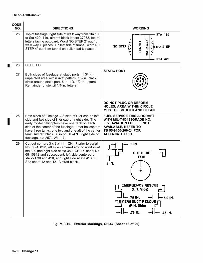
TM 55-1500-345-23
CODENO. DIRECTIONS WORDING
25 Top of fuselage, right side of walk way from Sta 160to Sta 420, 1-in. aircraft black letters 37038, top ofletters facing outboard, Word NO STEP 2" out fromwalk way, 6 places. On left side of tunnel, word NOSTEP 4" out from tunnel on bulk head 6 places.
26 DELETED
STATIC PORT27 Both sides of fuselage at static ports. 1 3/4-in.
unpainted area within rivet pattern, 1/2-in. blackcircle around static port, 6-in. I.D. 1/2-in. letters.Remainder of stencil 1/4-in. letters.
DO NOT PLUG OR DEFORMHOLES; AREA WITHIN CIRCLEMUST BE SMOOTH AND CLEAN.
28 Both sides of fuselage. Aft side of f ller cap on leftside and fwd side of f ller cap on right side. Theearly model helicopters have one tank on eachside of the center of the fuselage. Later helicoptershave three tanks, one fwd and one aft of the centertank. Aircraft black. Also on CH-47D, right side offuselage, sta 257., WL -17.
FUEL SERVICE THIS AIRCRAFTWITH MIL-T-83133GRADE NO.JP-8 AVIATION FUEL. IF NOTAVAILABLE, REFER TOTB 55-9150-200-24 FORALTERNATE FUEL
29 Cut out corners 3 x 3 x 1 in. CH-47 prior to serialNo. 68-15812, left side centered around window atsta 300 and right side at sta 380. CH-47, serial No.68-15812 and subsequent, left side centered onsta 221.30 and 420, and right side at sta 416.50.See sheet 12 and 13. Aircraft black.
Figure 9-10. Exterior Markings, CH-47 (Sheet 16 of 29)
9-70 Change 11
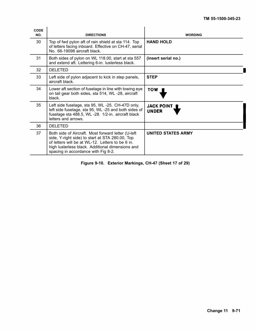
TM 55-1500-345-23
CODENO. DIRECTIONS WORDING
30 Top of fwd pylon aft of rain shield at sta 114. Topof letters facing inboard. Effective on CH-47, serialNo. 66-19098 aircraft black.
HAND HOLD
31 Both sides of pylon on WL 118.00, start at sta 557and extend aft. Lettering 6-in. lusterless black.
(insert serial no.)
32 DELETED
33 Left side of pylon adjacent to kick in step panels,aircraft black.
STEP
34 Lower aft section of fuselage in line with towing eyeon tail gear both sides, sta 514, WL -28, aircraftblack.
35 Left side fuselage, sta 95, WL -25. CH-47D only,left side fuselage, sta 95, WL -25 and both sides offuselage sta 488.5, WL -28. 1/2-in. aircraft blackletters and arrows.
36 DELETED
37 Both side of Aircraft. Most forward letter (U-leftside, Y-right side) to start at STA 280.00, Topof letters will be at WL-12. Letters to be 6 in.high lusterless black. Additional dimensions andspacing in accordance with Fig 8-2.
UNITED STATES ARMY
Figure 9-10. Exterior Markings, CH-47 (Sheet 17 of 29)
Change 11 9-71

TM 55-1500-345-23
CODE NO. DIRECTIONS WORDING
38 Both sides fuselage at sta 241, WL-34, aircraftblack.
FUSLG JACKPOINT ANDMOORINGPOINT UNDER
39 Both sides of fuselage, 1/2-in. aircraft black lettersand arrow, sta 496, WL -28
MOORINGPOINT UNDER
40 Aircraft black.
NOTE
Below access door at sta 169, sta 163,WL-23.
115/208 V 400 CYCLE A.C.
41 Above external power access panel, Sta 169, onleft side, aircraft black.
EXT PWRDC-AC
42 Fwd of external power access panel on left side,Sta 166, 1/2-in. aircraft black letters.
28 V.D.C.
43 Below door jettison handle on left side, Sta 93, WL24, aircraft black.
44 Left side of fuselage aft of cabin window, Sta 93,WL 11.50. First two lines 1-in, remaining lines1/2-in. aircraft black.
U.S. ARMY MODEL CH-47A (B, C or D)U.S.A. SERIAL NO. (insert serial no.)
Service this aircraft with MIL-T-83133 grade No.JP-8 aviation fuel. If not available refer to TB55-9150-200-24for alternate fuel.
45 Below lower .ight compartment side window in linewith door jettison handle on left side aircraft black.FOR TACTICAL HELICOPTERS ONLY.
Figure 9-10. Exterior Markings, CH-47 (Sheet 18 of 29)
9-72 Change 12

TM 55-1500-345-23
CODENO. DIRECTIONS WORDING
46 DELETE
47 DELETED
48 DELETED
49 Authorized placement of unit insignia is on noseaccess panel.
50 Above battery vent, left side of fuselage, Sta 188.1/4-in. aircraft black letters.
BATTERY VENT
51 On battery access panel, left side of fuselage, Sta188, WL 16, aircraft black.
BATTERYINSIDE
52 Black walkway material on indicated shaded areas
53 Paint code 1/4-in. black letters left side of fuselage,Sta 118, WL -28.**Contractor will insert their name code.
**WP1-P2-L3 DateWP - indicate wash primer usedP - indicate primer usedL - indicate lacquer used (if req’d)C - indicate coating used (if req’d)
54 DELETED
55 Both sides of fwd pylon fairing, 1/2-in. black letters,Sta 97.50 WL +67.
ACCESSFWD ROTOR SYSHYDR COMPTWORK PLATFORM
56 DELETED
57 Both sides of fwd pylon, Sta 123, WL 63.50 aircraftblack.
Figure 9-10. Exterior Markings, CH-47 (Sheet 19 of 29)
Change 12 9-73

TM 55-1500-345-23
CODENO. DIRECTIONS WORDING
58 Left side of fuselage, Sta 204, above draintube. 1/4-in. black letters.
TUNNEL DRAIN
59 Both sides of fuselage, 3places, Sta 226, 355and 485, WL -34.0. 1/2-in. black letters.
60 DELETE
61 Both sides of fuselage, Sta 436.0, WL -23.0.Centered on forward landing gear access door,black.
ACCESS FUEL SYSTEM INSP.
62 On landing gear struts, 1/4-in. black letters. TIREPRESSURE*88PSI
63 Both sides of fuselage, aircraft black. CH-47D,both sides of fuselage, 14 places at Sta 194.1,235.2, 261.2, 363.6, 379.0, 396.2.
FUELDRAIN
64 Both sides of fuselage, 2 places, Sta 261 and355. CH-47D only, Sta 261, 370.50. Blackletters.
Disconnect electrical plugs in fuel cell accesspanel before dropping tank.
65 DELETE
Figure 9-10. Exterior Markings, CH-47 (Sheet 20 of 29)
9-74 Change 12

TM 55-1500-345-23
CODENO. DIRECTIONS WORDING
66 DELETE
67 Both sides of fuselage centered on access plate,aircraft black, Sta 381 and 449.
ACCESS FUELSYSTEM INSP
68 Left and right aft work platform, centered onplatform at WL -2.50, black letters.
WORK PLATFORM
69 Both sides of fuselage, fore and aft of work platformabove support point at Sta 474.0 and 521.0, WL-6.0 black letters.
70 Both sides of fuselage, Sta 485, WL -34. 1/2-in.black letters as required per model helicopter.
71 Left side of fuselage, Sta 546.50, WL 15, blackletters.
ACCESSAPP EMERGFLUID SHUT OFF
72 Left side of fuselage, Sta 543, WL 50. First line1-in. black letters, remaining letters 1/4-in., locatedin front of each overboard drain tube.
NOTE
Applicable on CH-47, serial No. 67-18494and subsequent.
ENGINEDRAINS*STARTER RELIEFVALVE DRAINHYDRAULIC DRAINAFT XMSN DRIP PANENGINE COMB CHAMBENGINE BREATHERENGINE MANF
73 Both sides of engine cowling below screened airintake, Sta 486, WL 46.0, black letters.
ACCESS ENGINEQUICKDISCONNECT
74 Both sides of rear pylon, Sta 471, WL 79, blackletters.
Figure 9-10. Exterior Markings, CH-47 (Sheet 21 of 29)
Change 12 9-75

TM 55-1500-345-23
CODENO. DIRECTIONS WORDING
75 Both sides of rear pylon, Sta 457, WL 106.5, fwd ofscreened air intake, black letters.
ACCESS XMSNOIL COOLER
76 On CH-47, serial No. 65-7966 to 65-8025, left sideof rear pylon, below screened area, black letters.
ACCESS ENGINE GEARBOX CHIP DETECTORS
77 On outboard side of #1 engine and inboard side of#2 engine, aft of access door, black letters.
ACCESSOIL QUANTITYINDICATOR
78 DELETE
79 DELETE
80 Left side of fuselage near top of rear pylon, Sta550, WL 128, black letters
ACCESS THRUST BEARING& WORK PLATFORM
81 DELETE
82 Both side of pylon centered on access door, Sta564, WL 85.0, black letters.
ACCESSXMSN
83 DELETE
84 Right side of fuselage under overboard drain, Sta107, WL 15, 1/2 in. black letters.
WATER DRAINHEATER INLET
85 Right side of fuselage above access door, Sta 114,WL -1, black letters.
INPHJACK
86 DELETE
87 Right side of fuselage above overboard drain line,Sta 101, WL -34.5 1/2-in. black letters.
HEATER FUEL DRAIN
88 Right side of fuselage on upper door, fwd of releasehandle, Sta 127, WL -2.5, black letters.
LIFT DOOR UP
Figure 9-10. Exterior Markings, CH-47 (Sheet 22 of 29)
9-76 Change 12

TM 55-1500-345-23
CODENO. DIRECTIONS WORDING
89 Both sides of aft fuselage inside insp panel,black letters.
NO HAND HOLD
90 Right side of fwd pylon fairing, Sta 78, WL 66,black letters.
XMSN OILFILLER INSIDE
91 Right side of fuselage on access door, Sta187, WL -15, black letters.
ACCESSA.C. POWEREQUIP
92 Right side of fuselage adjacent to each side ofstep kick in door panel above water line
STEP
NOTE
The first two lower steps on the rightside of the pod have a folding hingetype door. This marking goes on thedoor of the step below the door knob.First line is 1-in, remainder is 1/2-in.black letters.
STEPPULL KNOB DOWNAND OUT TOOPEN STEP
93 Both sides of fuselage, step guide above eachstep. 1/4-in. wide, 12-in., 15-in., or 27-in.lengths, black letters.
94 Outboard side of each mounting pitot tube.First line centered horizontally on tube, secondline below center. 1/2-in. black letters.
NO PUSHKEEP OFF
95 Right side of fuselage, aft small access plate,on larger access plate, Sta 494.50, blackletters.
ACCESSRAMPCONTROLDN-STOP-UP
96 Right side of fuselage above access plate, Sta487.50 black letters.
INPHJACK
97 Right side of fuselage on aft access panel neartail, Sta 561, WL 15, black letters.
HYD SYSTEMTESTPANEL
98 DELETE
Figure 9-10. Exterior Markings, CH-47 (Sheet 23 of 29)
Change 12 9-77
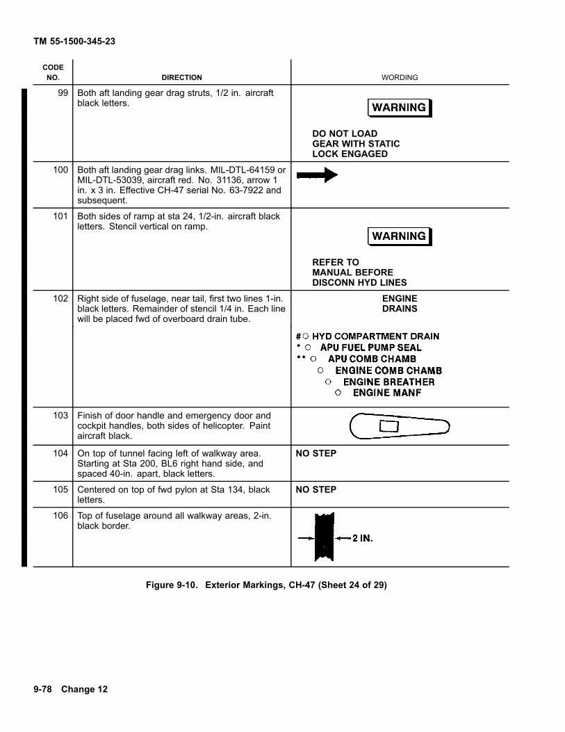
TM 55-1500-345-23
CODENO. DIRECTION WORDING
99 Both aft landing gear drag struts, 1/2 in. aircraftblack letters.
DO NOT LOADGEAR WITH STATICLOCK ENGAGED
100 Both aft landing gear drag links. MIL-DTL-64159 orMIL-DTL-53039, aircraft red. No. 31136, arrow 1in. x 3 in. Effective CH-47 serial No. 63-7922 andsubsequent.
101 Both sides of ramp at sta 24, 1/2-in. aircraft blackletters. Stencil vertical on ramp.
REFER TOMANUAL BEFOREDISCONN HYD LINES
102 Right side of fuselage, near tail, first two lines 1-in.black letters. Remainder of stencil 1/4 in. Each linewill be placed fwd of overboard drain tube.
ENGINEDRAINS
103 Finish of door handle and emergency door andcockpit handles, both sides of helicopter. Paintaircraft black.
104 On top of tunnel facing left of walkway area.Starting at Sta 200, BL6 right hand side, andspaced 40-in. apart, black letters.
NO STEP
105 Centered on top of fwd pylon at Sta 134, blackletters.
NO STEP
106 Top of fuselage around all walkway areas, 2-in.black border.
Figure 9-10. Exterior Markings, CH-47 (Sheet 24 of 29)
9-78 Change 12

TM 55-1500-345-23
CODENO. DIRECTIONS WORDING
107 Top of fuselage, right side, fwd on access door,Sta 152. Top of black letters facing outboard.Also right side aft, Sta 443.5 on CH-47 serialNo. 66-19098 thru 67-18484.
ACCESSMAINTDAVIT
108 Top of fuselage, right side aft of walkwayindent, Sta 175. Also aft right side, of fuselageat Sta 416. 1/2-in. black letters.
MAINT CRANE AZIMUTH PT.REPLACE SCREW AFTER USING
109 Three places on top of fuselage tunnel, Sta180, 303, and 384. Top of black letters facingleft.
ACCESS DRIVESHAFT COUPLING
110 Top center of both sides of fuselage, Sta 317.A 2-in. lusterless black circle on the fittingcover.
111 Top center of both sides of fuselage at fitting.Stencil to be outboard of fitting, top of blackletters facing outboard.
SPT. PTBLADE RACK
112 Top and bottom of left and right gear boxaccess cover. Top of black letters face aft.
REMOVEGEAR BOXACCESS
113 DELETED
114 Top of left and right engine pod drive shaftfairing. Top of black letters facing aft.
ACCESSDRIVE SHAFT
115 On top of left and right nacelle on access plate.Top of black letters facing aft.
ACCESSOIL FILTER
116 Two places on top of left and right nacelle. Aftof oil filler access and fwd of circular hole infairing. Top of black letters face aft.
ACCESSENGINE HOIST
117 Top of left and right engine nacelle, fwd oftail pipe. Top of black letters facing outboard,arrows to point aft.
NO STEPOR HAND HOLD
118 On top sides of fwd and aft rotor blade rainshield. Paint rain shield lusterless black(overspray rain shield). Apply stencils 120°apart, 3 places on each rain shield. This stencilis located outboard of each rotor blade pitchlink cutout hole.
NO STEP
Figure 9-10. Exterior Markings, CH-47 (Sheet 25 of 29)
Change 12 9-79

TM 55-1500-345-23
CODENO. DIRECTIONS WORDING
119 DELETED
120 Bottom centerline of fuselage. One place on frontlower section of nose area. Two places on nose atmirror support brackets. 1/2-in. black letters.
MIRRORSPT PT
121 Bottom of fuselage, right side, at sta 98.0. 1/4-in.black letters.
XMSN OIL DRAIN
122 Bottom of fuselage at drain lines, black letters.
123 Left side of fuselage, bottom of acft. sta 187, 1/4-in.black letters.
BATTERY DRAIN
124 On aft loading ramp emergency escape panel.1-1/2 in. black band around push button
125 DELETED MAGNETIC PLUG126 DELETED
127 DELETE
128 Centered on nose panel, above door catch blackletters.
ACCESS
129 DELETE
Figure 9-10. Exterior Markings, CH-47 (Sheet 26 of 29)
9-80 Change 12
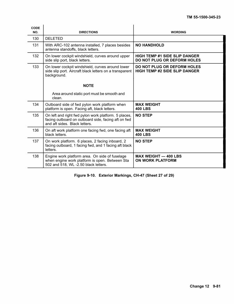
TM 55-1500-345-23
CODENO. DIRECTIONS WORDING
130 DELETED
131 With ARC-102 antenna installed, 7 places besidesantenna standoffs, black letters.
NO HANDHOLD
132 On lower cockpit windshield, curves around upperside slip port, black letters.
HIGH TEMP #1 SIDE SLIP DANGERDO NOT PLUG OR DEFORM HOLES
133 On lower cockpit windshield, curves around lowerside slip port. Aircraft black letters on a transparentbackground.
DO NOT PLUG OR DEFORM HOLESHIGH TEMP #2 SIDE SLIP DANGER
NOTE
Area around static port must be smooth andclean.
134 Outboard side of fwd pylon work platform whenplatform is open. Facing aft, black letters.
MAX WEIGHT400 LBS
135 On left and right fwd pylon work platform. 5 places,facing outboard on outboard side, facing aft on fwdand aft sides. Black letters.
NO STEP
136 On aft work platform one facing fwd, one facing aftblack letters.
MAX WEIGHT400 LBS
137 On work platform. 6 places, 2 facing inboard, 2facing outboard, 1 facing fwd, and 1 facing aft blackletters.
NO STEP
138 Engine work platform area. On side of fuselagewhen engine work platform is open. Between Sta502 and 518, WL -2.50 black letters.
MAX WEIGHT — 400 LBSON WORK PLATFORM
Figure 9-10. Exterior Markings, CH-47 (Sheet 27 of 29)
Change 12 9-81

TM 55-1500-345-23
CODENO. DIRECTIONS WORDING
139 DELETED
140 DELETED
141 DELETED
142 DELETED
143 Both sides of fwd fuselage, 1/2-in. black letters,sta 72, WL -19.
WHEN INSTALLING DOOR REFER TOTM 1-1520-240-23&P FOR PROPER IN-STALLATION AND ADJUSTMENT
144 Left side aft pylon, 1/2-in. aircraft black letters, sta472, WL 73.
LS ENGINE XMSNFILTER AND DRAIN ACCESS
145 Left side fuselage, below Code 52, paint aircraftblack.
NOTE
Date shown on stencil is date aircraft waspainted with MIL-DTL-64159 or MIL-DTL-53039
146 Left side fuselage, 1/2-in. black letters, sta 157.50,WL -14.
GROUND TEST CONNECTIONFLIGHT CONTROL SYSTEM 13000 PSIUSE HYDRAULIC FLUIDMIL-H-83282
147 Both sides fuselage, 1/2-in. black letters, sta 173,WL -15.
ACCESSAC-DC POWER EQPT
148 Right side fwd pylon, 1/2-in. aircraft black letters,sta 153, WL 72.
ACCESS HYDRRESERVOIR
149 Both sides fuselage, 1/2-in. black letters, sta 245,WL -13.
ACCESSLANDING GEARSERVICE
150 Both sides of pylon, 1/2-in. aircraft black letters,sta 490.5, WL 81.5.
ACS HYDRRSVR INSP
Figure 9-10. Exterior Markings, CH-47 (Sheet 28 of 29)
9-82 Change 12
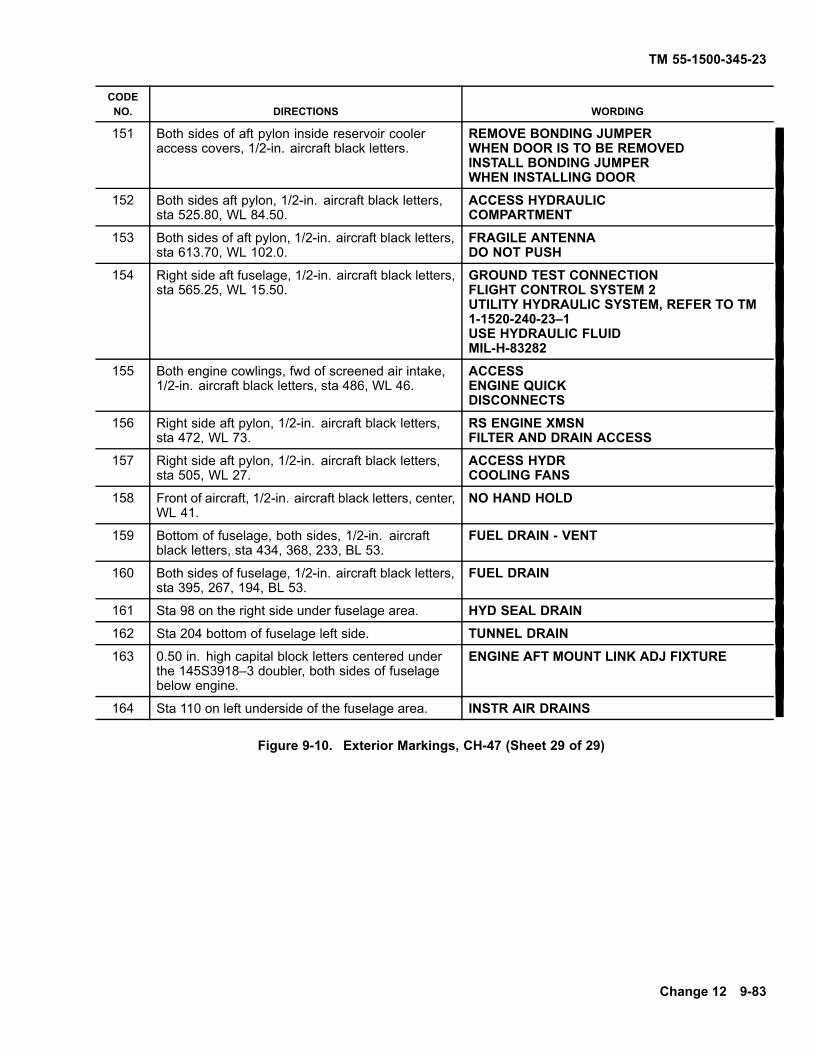
TM 55-1500-345-23
CODENO. DIRECTIONS WORDING
151 Both sides of aft pylon inside reservoir cooleraccess covers, 1/2-in. aircraft black letters.
REMOVE BONDING JUMPERWHEN DOOR IS TO BE REMOVEDINSTALL BONDING JUMPERWHEN INSTALLING DOOR
152 Both sides aft pylon, 1/2-in. aircraft black letters,sta 525.80, WL 84.50.
ACCESS HYDRAULICCOMPARTMENT
153 Both sides of aft pylon, 1/2-in. aircraft black letters,sta 613.70, WL 102.0.
FRAGILE ANTENNADO NOT PUSH
154 Right side aft fuselage, 1/2-in. aircraft black letters,sta 565.25, WL 15.50.
GROUND TEST CONNECTIONFLIGHT CONTROL SYSTEM 2UTILITY HYDRAULIC SYSTEM, REFER TO TM1-1520-240-23–1USE HYDRAULIC FLUIDMIL-H-83282
155 Both engine cowlings, fwd of screened air intake,1/2-in. aircraft black letters, sta 486, WL 46.
ACCESSENGINE QUICKDISCONNECTS
156 Right side aft pylon, 1/2-in. aircraft black letters,sta 472, WL 73.
RS ENGINE XMSNFILTER AND DRAIN ACCESS
157 Right side aft pylon, 1/2-in. aircraft black letters,sta 505, WL 27.
ACCESS HYDRCOOLING FANS
158 Front of aircraft, 1/2-in. aircraft black letters, center,WL 41.
NO HAND HOLD
159 Bottom of fuselage, both sides, 1/2-in. aircraftblack letters, sta 434, 368, 233, BL 53.
FUEL DRAIN - VENT
160 Both sides of fuselage, 1/2-in. aircraft black letters,sta 395, 267, 194, BL 53.
FUEL DRAIN
161 Sta 98 on the right side under fuselage area. HYD SEAL DRAIN162 Sta 204 bottom of fuselage left side. TUNNEL DRAIN163 0.50 in. high capital block letters centered under
the 145S3918–3 doubler, both sides of fuselagebelow engine.
ENGINE AFT MOUNT LINK ADJ FIXTURE
164 Sta 110 on left underside of the fuselage area. INSTR AIR DRAINS
Figure 9-10. Exterior Markings, CH-47 (Sheet 29 of 29)
Change 12 9-83

TM55-1500-345-23
Figure 9-11. Station Diagram, CH-47.
9-84
TM 55-1500-345-23
SECTION IV DELETED
Pages 9-86 through 9-100 and Figures 9-12 through9-16 have been deleted
Change 12 9-85/(9-86 Blank)


TM 55-1500-345-23
SECTION V DELETED
Pages 9-102 through 9-108 and Figures 9-17 through9-20 have been deleted
Change 12 9-101/(9-102 Blank)


TM 55-1500-345-23
SECTION VI OH-58 ILLUSTRATIONS
1. MIL-DTL-64159 or MIL-DTL-53039, Aircraft Green (entire aircraft,except as noted).
2. MIL-DTL-64159 or MIL-DTL-53039, Aircraft Black.
3. MIL-DTL-64159 or MIL-DTL-53039, Dark Sand (entire aircraft or highconspicuous paint scheme when authorized, desert operations only).See Paragraph 5-11.
4. MIL-DTL-64159 or MIL-DTL-53039, Aircraft White (entire aircraft orhigh conspicuous paint scheme when authorized, arctic operationsonly). See Paragraph 5-11.
5. MIL-P-21600, Fluorescent Red-Orange. ANA #633 (trainingaircraft-high visibility, only where authorized).
Figure 9-21. Tactical Paint Scheme, OH-58
Change 12 9-109

TM 55-1500-345-23
1. MIL-DTL-64159 or MIL-DTL-53039, aircraft green (entire aircraft,except as noted).
2. MIL-DTL-64159 or MIL-DTL-53039, aircraft black.
3. MIL-P-21600, fluorescent red-orange, ANA #633 (shaded areas only).
Figure 9-22. Non-Tactical Arctic/Desert Paint Scheme, OH-58
9-110 Change 12

TM 55-1500-345-23
Figure 9-23. Interior and Exterior Markings, OH-58 (Sheet 1 of 13).
Change 5 9-111

Figu
re 9
-23.
Inte
rior
TM
55-
1500
-345
-23
9-11
2C
hang
e 8

Figure 9-23
TM
55-1500-345-23
Ch
ang
e 5
9-1
13

Figu
re 9
-23
TM
5
5-1
50
0-3
45
-23
9-11
4C
han
ge
5
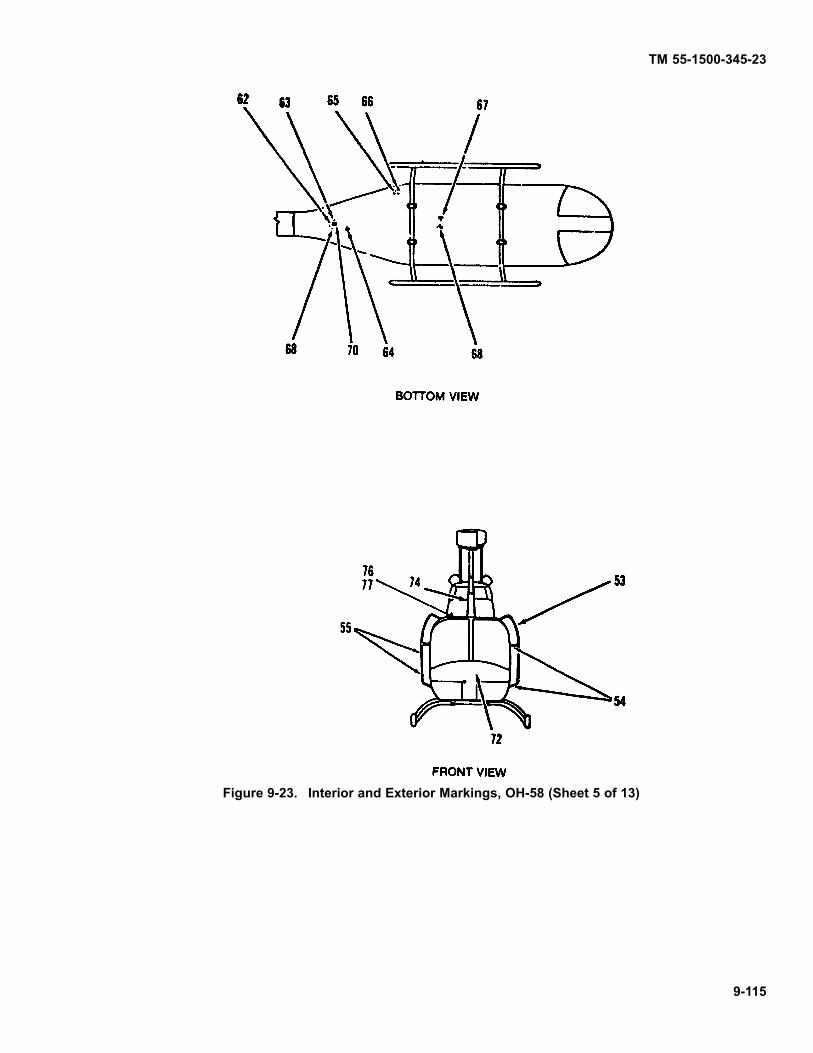
TM 55-1500-345-23
Figure 9-23. Interior and Exterior Markings, OH-58 (Sheet 5 of 13)
9-115

TM 55-1500-345-23
CODENO. DIRECTIONS WORDING
1 Right side, aft of engine compartmenton aft fairing. 5/8-in. MIL-DTL-64159 orMIL-DTL-53039 aircraft black, #37038letters.
ENGINE OILABOVE 25°F MIL-L-23699BELOW 25°F MIL-L-7808
2 Right side, above Code 1. 5/8-in. aircraftblack letters.
ENGINE OIL FILLER CAP ACCESS
3 Paint a black ground symbol, shade 37038,dimensions per MIL-C-83413/9-2.
4 Below forward edge of engine cowl sidepanel, right side. 5/8-in. aircraft blackletters.
CABIN ROOF DRAIN
5 Paint fuel .ller cap same color as thefuselage. Paint a 1 inch wide ring aroundfiller aircraft black. 1 inch ring to be 2 inchfrom cap center.
6 Right side below right air intake screen.5/8-in. aircraft black letters, OH-58A, C andD.
OH-58D(I) see NOTE in wording.
TRANSMISSION OILLEVEL ACCESSABOVE - 25°F MIL-L-23699BELOW - 25°F MIL-L-7808
NOTE
TRANSMISSION OIL LEVEL ACCESSABOVE - 40°F DOD-L-85734 BELOW -40°FMIL-L-7808
7 Locate on both sides fwd fairing, 2 1/2in. above roof skin and 3 in. fwd of mastcenterline. 6 in. high and 4 in. wide aircraftblack letters with 1 in. spacing betweenletters.
(RADIO CALL NUMBER)
8 Inside both passenger doors. 5/8-in.MIL-DTL-64159 or MIL-DTL-53039, aircraftwhite #37875 letters.
OPEN
9 Inside both passenger doors. 5/8-in. aircraftwhite letters.
CLOSED
10 Inside of both crew doors. 5/8-in. aircraftwhite letters.
OPEN
11 Inside of both crew doors. 5/8-in. aircraftwhite letters.
CLOSED
12 Above static ports, both sides of fuselage.3/8-in. aircraft black letters.
DO NOT PLUGOR DEFORM HOLES
Figure 9-23. Interior and Exterior Markings, OH-58 (Sheet 6 of 13)
9-116 Change 12

TM 55-1500-345-23
CODENO. DIRECTIONS WORDING
13 Both side of helicopters, a 5/8 inch wide bandwith a 2-5/8 inch outside diameter, aircraftblack.
14 Below static port, both sides. 3/8-in. aircraftblack letters.
STATIC PORT
15 Both sides of aircraft, fwd of sta 55.16 on lowerside, aircraft black.
JACK POINT
16 Both sides of aircraft, fwd of sta 55.16 nearjack points aircraft black.
MOOR
17 Exterior on fwd and aft doors, above doorhandles, both sides of fuselage. 1-3/8 in.aircraft black letters.
EXIT RELEASE
18 Exterior on fwd and aft doors, below doorhandles, both sides of fuselage. 1-3/8 in.aircraft black letters.
TURN
19 Exterior on fwd and aft doors, below doorhandles, both sides of fuselage. 1-3/8 in.aircraft black letters.
PULL
20 Exterior on fwd and aft doors, below doorhandles, both sides of fuselage. Aircraft blackletters.
21 On back of panel, right side of aircraft, abovefuel filler. 5/8-in. orange-yellow letters.
STRUCTURAL PANELREQUIRED FOR GROUNDRUN AND FLIGHT
22 On right side of aircraft, below fuel filler cap.5/8 in. aircraft black letters.
CAP .71.5 U.S. GAL USE MIL-T-5624 GRADE JP-4 orJP-5. If not available refer to TB 55-9150-200-24 foralternate fuel
Figure 9-23. Interior and Exterior Markings, OH-58 (Sheet 7 of 13)
Change 5 9-117

TM 55-1500-345-23
CODENO. DIRECTIONS WORDING
23 On right side of aircraft, below fuel filler cap.1/4-in. aircraft black letters.
FOR OPERATING TEMPERATURESBELOW 40°F O.A.T., FUEL USEDMUST CONTAIN PFA 55MB ADDITIVE.CONCENTRATION TO BE .06% - .15%BY VOLUME
24 On right side of aircraft, below and aft of fuelfiller cap. NATO refueling symbol aircraft black.
25 Right side of aircraft aft and below fuel filler,above external power receptacle. 5/8 in.aircraft black letters.
BATTERY VENT
26 Right side of aircraft on external power door.1/2 in. aircraft black letters.
EXTERNAL POWER
27 AFT of external Power Receptacle.
28 Located on interior and exterior of tail boominspection plate. 5/8-in. aircraft black letters.
STRUCTURAL PANEL REQUIRED GROUND RUN ANDFLIGHT
29 Both sides of aircraft fwd of tail boom onintermediate section. 5/8-in. aircraft blackletters.
NO PUSH
30 OH-58A. On both sides of tail boom, centerline19 in. aft of stabilizer. OH-58C. 15-in. aft ofstabilizer, aircraft black letters and arrows.
31 Both sides of tail cone, 5/8 inch aircraft blackletters.
NO PUSH
32 Locate on inside door post in two places bothsides of aircraft. 5/8in. orange-yellow letters.
EMERGENCY RELEASE
33 Below jettison handles, both sides. Inside ondoor posts, 1-in. aircraft white letters.
PULL
Figure 9-23. Interior and Exterior Markings, OH-58 (Sheet 8 of 13)
9-118 Change 12

TM 55-1500-345-23
CODENO. DIRECTIONS WORDING
34 Below jettison handles on pilot and copilotdoor posts. Aircraft white arrows pointing aft.
35 Paint both jettison handles inside of aircraftwith 1/8 inch wide alternate orange-yellowand black stripes.
36 Left side of aircraft, aft of air louvers, on aftfairing. 5/8 in. aircraft black letters.
OIL TANK DRAINACCESS
37 Aft end of aft fairing, both sides. 5/8 in.aircraft black letters.
DISCONNECT ELECTRICAL WIRING BE-FORE REMOVING TAIL BOOM.
38 0.30 in. diameter dot on one end of tail rotoryoke, corresponding end of crosshead andcorresponding pitch link assembly. PaintMIL-DTL-64159 or MIL-DTL-53039 aircraftred, #31136.
39 0.30 in. diameter dot on one end of tail rotoryoke, corresponding end of crosshead andcorresponding pitch link assembly. PaintMIL-DTL-64159 or MIL-DTL-53039 aircraftwhite, #37875.
40 Left side of vertical fin, adjacent to tail rotorgear box. 5/8-in. aircraft black letters, 0.38in. space between lines, OH-58A, C and D.
SERVICE GEAR BOXMIL-L-23699 ABOVE - 25°FMIL-L-7808 BELOW - 25°F
OH-58D(I) see NOTE in wording.NOTE
ABOVE - 40°F DOD-L-85734BELOW- 40°F MIL-L-7808
41 Both sides of Tail Boom, most AFT letter(Y-left side U-right side) to be 4.0 inchforward of stabilizer. Letters centered oncenter line of tail boom. Letters to be 6in. high aircraft black #37038. Additionaldimensions and spacing in accordance withFig. 8-2.
UNITED STATES ARMY
42 Left side of aircraft, upper aft corner ofavionics compartment door. 5/8-in. aircraftblack letters.
BATTERY ACCESS
43 Left side of aircraft, on small door forwardof the RF antenna and above the Avionicscompartment door. 5/8 inch aircraft blackletters.
STEP
Figure 9-23. Interior and Exterior Markings, OH-58 (Sheet 9 of 13)
Change 12 9-119

TM 55-1500-345-23
CODENO. DIRECTIONS WORDING
44 Left side of aircraft, aft of passenger door.First two lines 1-in. aircraft black letters.Remainder 1/2-in. letters.
NOTE
Transfer data to right side of heli-copter above the fuel filler cap whenMWO 55-1520-228-50-53, ATS, hasbeen applied.
U.S. ARMY OH-58AU.S.A. SERIAL NO. (Insert serial no.)Service this aircraftwith MIL-T-5624 GradeJP-4 aviation fuel
45 Left side of aircraft, lower fuselage, fwd ofantenna. 1/2-in. aircraft black letters.
IF NOT AVAILABLE REFER TO TB 55-9150-200-24FOR ALTERNATE FUEL
46 Interior, center on crew and passengerdoors. 1-in. orange-yellow letters.
EMERGENCY EXIT
47 Interior of aircraft on passenger door post,below upper hinges. Paint aircraft whitearrows pointing fwd.
48 Interior of aircraft on passenger door posts,below upper hinges. 5/8 inch aircraft whitearrow pointing fwd.
PUSH
49 Interior of aircraft on passenger door posts,below upper hinges. Tops of letters pointingforward. 1-3/8-in. orange-yellow letters.
EMERGENCY RELEASE
50 Lower left and right sides of aircraft, belowcrew doors. Aircraft black arrows pointingdown at jack points.
51
52
Figure 9-23. Interior and Exterior Markings, OH-58 (Sheet 10 of 13)
9-120 Change 5

TM 55-1500-345-23
CODENO. DIRECTIONS WORDING
53 Outside surface of left and right antennas. Tobe read from fwd side of antennas. 5/8-in.letters. MIL-DTL-64159 or MIL-DTL-53039,olive drab, #34037 letters on black background.MIL-DTL-64159 or MIL-DTL-53039, Black#37038 letters on aircraft green background.
NO HAND HOLD
54 Center and lower flat areas of left and rightantennas. To be read from fwd side of aircraft5/8-in. MIL-DTL-64159 or MIL-DTL-53039,olive drab #34037 letters in black background.MIL-DTL-64159 or MIL-DTL-53039, black#37038 letters on aircraft green background.
NO STEP
55 Center and lower outboard surface of left andright antennas. To be read from fwd sideof aircraft. 5/8-in. letters. MIL-DTL-64159or MIL-DTL-53039 olive drab #34037 letterson black background. MIL-DTL-64159 orMIL-DTL-53039, black #37038 letters onaircraft green background.
NO PUSH
56 Top side of both landing skids above tow rings.Aircraft black.
57 Top side of both landing skids above tow rings.5/8-in. aircraft black letters.
TOW
58 Upper and lower surfaces of main rotor gripand attaching linkage for each grip. 1/2-in.aircraft red dots.
59 Upper and lower surfaces of main rotor gripand attaching linkage for each grip. 1/2-in.aircraft white dots.
Figure 9-23. Interior and Exterior Markings, OH-58 (Sheet 11 of 13)
Change 12 9-121

TM 55-1500-345-23
CODENO. DIRECTIONS WORDING
60 Leading and trailing edge of stabilizer, bothsides 5/8 in aircraft black letters. OH-58C(VOR antenna, right and left side, 4 places).5/8-in. aircraft black letters.
NO PUSH
61 Apply walkway coating MIL-W-5044, Type II,both sides of aircraft between skin splices atsta 88.27 to 122.0. Paint to match existingcolor scheme.
62 Underside of fuselage, on centerline, aft of jackpoint 5/8-in. aircraft black letters.
JACK POINT
63 Underside of fuselage, right of centerline, leftof jack point. Aircraft black.
64 Underside of fuselage, left of centerline, fwd ofjack point. 5/8-in. aircraft black letters.
ENGINE OIL TANKDRAIN
65 Underside of fuselage, right side aft of aft crosstube. 5/8-in. aircraft black letters.
ENGINE DECK DRAIN
66 Underside of fuselage, right side aft of aft crosstube. 5/8-in. aircraft black letters.
FUEL CELL VENT
67 Underside of fuselage. Right side of centerline,between cross tubes. 5/8-in. aircraft blackletters.
PUMP SEAL DRAIN
68 Underside of fuselage. Left of centerline,between cross tubes. 5/8-in. aircraft blackletters.
DRAIN
69 Underside of fuselage. Left of centerline andjack point Aircraft black.
70 Underside of fuselage, fwd of jack point alongcenterline, 5/8-in. aircraft black letters.
MOOR
71 Non-tactical aircraft only. Paint tail skid orange.
72 Approved unit insignia.
Figure 9-23. Interior and Exterior Markings, OH-58 (Sheet 12 of 13)
9-122 Change 5

TM 55-1500-345-23
CODENO. DIRECTIONS WORDING
73 Immediately above fuel filler cap. 1/2-in.aircraft black letters.
AVOID CONTACT WITH INTERNAL FUEL LINESDURING SERVICING
74 Non-tactical aircraft only. Paint last 6 in. ofantenna orange.
75 OH-58C, center outboard of curved section fwdand aft of left and right antenna. 5/8-in. aircraftblack letters.
NO PUSH
76 Aft of fuel shut off lever, 1/2-in. aircraft blackletters on aircraft red background.
FUEL OFF
77 Fwd of fuel shut off lever, 1/2-in. aircraft blackletters on aircraft red background.
FUEL ON
78 Left side of aircraft, aft of passenger door,above Code 44, paint aircraft black. NOTE:Date shown on stencil is date aircraft paintedwith MIL-DTL-64159 or MIL-DTL-53039 paint.
79 Paint tail rotor gear box filler cap, orange-yellow.
Figure 9-23. Interior and Exterior Markings, OH-58 (Sheet 13 of 13)
Change 12 9-123

TM 55-1500-345-23
Figure 9-24. Interior Requirements to be Stenciled on the Back of Pilot’s and Co-Pilot’s Seat Backs,OH-58A/C (Sheet 1 of 2)
9-124

TM55-1500-345-23
NOTE Use this caution when seat back armor is not installed.Paint MIL-C-46168, orange-yellow, No. 33538.
Figure 9-24. Interior Requirements to be Stenciled on the Back of Pilot’sand Co-Pilot’s Seat Backs, OH-58A/C (Sheet 2 of 2)
9-125

TM55-1500-345-23
Figure 9-25. Station Diagram, OH-58
9-126

TM 55-1500-345-23
SECTION VII DELETED
Figure 9-26 has been deleted.
Change 12 9-127

TM 55-1500-345-23
SECTION VIII DELETED
Pages 9-129 through 9-176.1/(9-176.2 blank) and .g-ures 9-27 through 9-37 have been deleted.
9-128 Change 12

TM 55-1500-345-23
Figure 9-38 has been deleted.
Change 12 9-177

TM 55-1500-345-23
SECTION IX UH-60 ILLUSTRATIONS
1. MIL-DTL-64159 or MIL-DTL-53039, Aircraft Green (entire aircraft, except as noted).
2. MIL-DTL-64159 or MIL-DTL-53039, Aircraft Black.
3. MIL-DTL-64159 or MIL-DTL-53039, Dark Sand (entire aircraft or high conspicuouspaint scheme when authorized, desert operations only). See Paragraph 5-11.
4. MIL-DTL-64159 or MIL-DTL-53039, Aircraft White (entire aircraft or high conspicuouspaint scheme when authorized, arctic operations only). See Paragraph 5-11.
5. MIL-P-21600, Fluorescent Red-Orange. ANA #633 (training aircraft-high visibility,only where authorized).
6. MIL-C-83231, CLA TY2, Coating, Rain Erosion Resistant.
7. Do not paint.
Figure 9-39. Tactical Paint Scheme, UH-60
9-178 Change 12

TM 55-1500-345-23
1. MIL-DTL-64159 or MIL-DTL-53039, Aircraft Green (entire aircraft, except asnoted).
2. MIL-DTL-64159 or MIL-DTL-53039, Aircraft Black.
3. MIL-P-21600, fluorescent red-orange, ANA #633 (shaded areas only).
4. MIL-C-83231, CLA TY2, Cooling, Rain Erosion Resistant.
5. Do not paint
Figure 9-40. Non-Tactical Arctic/Desert Paint Scheme, UH-60
Change 12 9-179

TM 55-1500-345-23
Figure 9-41. Army Medical Service (Ambulance), UH-60
9-180 Change 1

TM 55-1500-345-23
Figure 9-42. Exterior and Interior Markings, UH-60 (Sheet 1 of 20).
Change 5 9-181


TM
55
-150
0-34
5-23
Ch
ang
e 5
9-18
3

TM55-1500-345-23
ESSS PECULIAR STENCILS
Figure 9-42. Exterior and lnterior Markings, UH-60(Sheet 4 of 20)
9-184
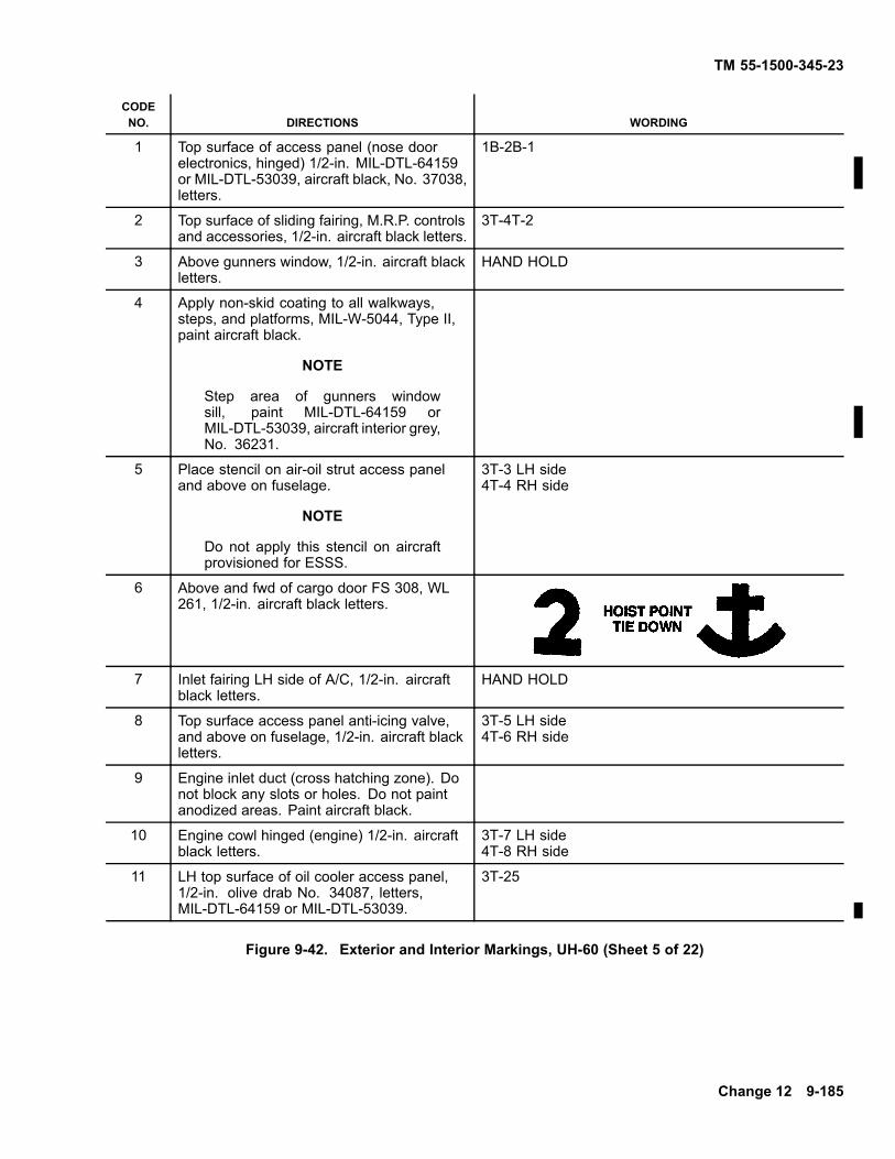
TM 55-1500-345-23
CODENO. DIRECTIONS WORDING
1 Top surface of access panel (nose doorelectronics, hinged) 1/2-in. MIL-DTL-64159or MIL-DTL-53039, aircraft black, No. 37038,letters.
1B-2B-1
2 Top surface of sliding fairing, M.R.P. controlsand accessories, 1/2-in. aircraft black letters.
3T-4T-2
3 Above gunners window, 1/2-in. aircraft blackletters.
HAND HOLD
4 Apply non-skid coating to all walkways,steps, and platforms, MIL-W-5044, Type II,paint aircraft black.
NOTE
Step area of gunners windowsill, paint MIL-DTL-64159 orMIL-DTL-53039, aircraft interior grey,No. 36231.
5 Place stencil on air-oil strut access paneland above on fuselage.
NOTE
Do not apply this stencil on aircraftprovisioned for ESSS.
3T-3 LH side4T-4 RH side
6 Above and fwd of cargo door FS 308, WL261, 1/2-in. aircraft black letters.
7 Inlet fairing LH side of A/C, 1/2-in. aircraftblack letters.
HAND HOLD
8 Top surface access panel anti-icing valve,and above on fuselage, 1/2-in. aircraft blackletters.
3T-5 LH side4T-6 RH side
9 Engine inlet duct (cross hatching zone). Donot block any slots or holes. Do not paintanodized areas. Paint aircraft black.
10 Engine cowl hinged (engine) 1/2-in. aircraftblack letters.
3T-7 LH side4T-8 RH side
11 LH top surface of oil cooler access panel,1/2-in. olive drab No. 34087, letters,MIL-DTL-64159 or MIL-DTL-53039.
3T-25
Figure 9-42. Exterior and Interior Markings, UH-60 (Sheet 5 of 22)
Change 12 9-185
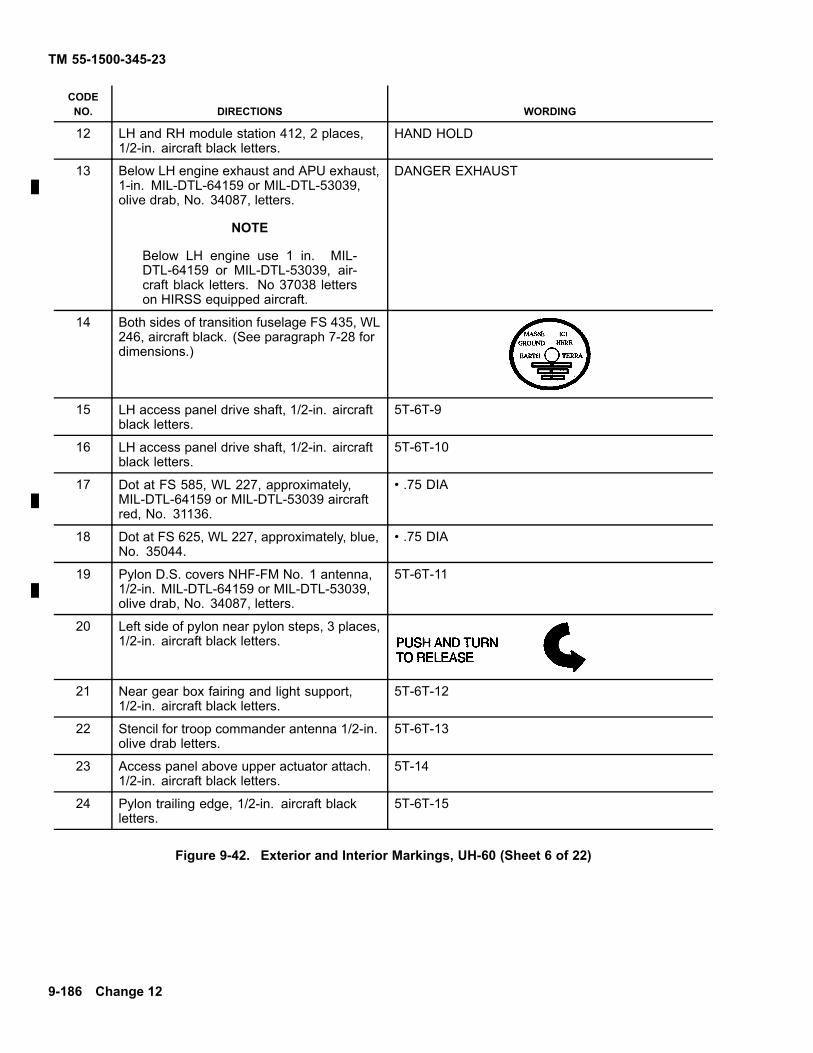
TM 55-1500-345-23
CODENO. DIRECTIONS WORDING
12 LH and RH module station 412, 2 places,1/2-in. aircraft black letters.
HAND HOLD
13 Below LH engine exhaust and APU exhaust,1-in. MIL-DTL-64159 or MIL-DTL-53039,olive drab, No. 34087, letters.
NOTE
Below LH engine use 1 in. MIL-DTL-64159 or MIL-DTL-53039, air-craft black letters. No 37038 letterson HIRSS equipped aircraft.
DANGER EXHAUST
14 Both sides of transition fuselage FS 435, WL246, aircraft black. (See paragraph 7-28 fordimensions.)
15 LH access panel drive shaft, 1/2-in. aircraftblack letters.
5T-6T-9
16 LH access panel drive shaft, 1/2-in. aircraftblack letters.
5T-6T-10
17 Dot at FS 585, WL 227, approximately,MIL-DTL-64159 or MIL-DTL-53039 aircraftred, No. 31136.
• .75 DIA
18 Dot at FS 625, WL 227, approximately, blue,No. 35044.
• .75 DIA
19 Pylon D.S. covers NHF-FM No. 1 antenna,1/2-in. MIL-DTL-64159 or MIL-DTL-53039,olive drab, No. 34087, letters.
5T-6T-11
20 Left side of pylon near pylon steps, 3 places,1/2-in. aircraft black letters.
21 Near gear box fairing and light support,1/2-in. aircraft black letters.
5T-6T-12
22 Stencil for troop commander antenna 1/2-in.olive drab letters.
5T-6T-13
23 Access panel above upper actuator attach.1/2-in. aircraft black letters.
5T-14
24 Pylon trailing edge, 1/2-in. aircraft blackletters.
5T-6T-15
Figure 9-42. Exterior and Interior Markings, UH-60 (Sheet 6 of 22)
9-186 Change 12
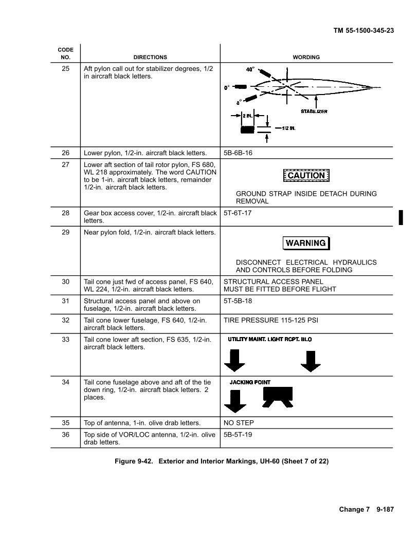
TM 55-1500-345-23
CODENO. DIRECTIONS WORDING
25 Aft pylon call out for stabilizer degrees, 1/2in aircraft black letters.
26 Lower pylon, 1/2-in. aircraft black letters. 5B-6B-16
27 Lower aft section of tail rotor pylon, FS 680,WL 218 approximately. The word CAUTIONto be 1-in. aircraft black letters, remainder1/2-in. aircraft black letters.
GROUND STRAP INSIDE DETACH DURINGREMOVAL
28 Gear box access cover, 1/2-in. aircraft blackletters.
5T-6T-17
29 Near pylon fold, 1/2-in. aircraft black letters.
DISCONNECT ELECTRICAL HYDRAULICSAND CONTROLS BEFORE FOLDING
30 Tail cone just fwd of access panel, FS 640,WL 224, 1/2-in. aircraft black letters.
STRUCTURAL ACCESS PANELMUST BE FITTED BEFORE FLIGHT
31 Structural access panel and above onfuselage, 1/2-in. aircraft black letters.
5T-5B-18
32 Tail cone lower fuselage, FS 640, 1/2-in.aircraft black letters.
TIRE PRESSURE 115-125 PSI
33 Tail cone lower aft section, FS 635, 1/2-in.aircraft black letters.
34 Tail cone fuselage above and aft of the tiedown ring, 1/2-in. aircraft black letters. 2places.
35 Top of antenna, 1-in. olive drab letters. NO STEP
36 Top side of VOR/LOC antenna, 1/2-in. olivedrab letters.
5B-5T-19
Figure 9-42. Exterior and Interior Markings, UH-60 (Sheet 7 of 22)
Change 7 9-187

TM 55-1500-345-23
CODENO. DIRECTIONS WORDING
NOTE
Aircraft equipped with CMWS, replace with 1 1/4-in black letters. No .ares.
37 Tail cone fwd section center stencil betweenFS 501 and FS 503, 1/2-in. aircraft blackletters.
PROVISION FOR CHAFFDISPENSER
38 LH side of A/C, FS 488, WL 232, aircraftblack.
39 Locate stencil at FS-485 above tie down ring,1/2-in. aircraft black letters.
40 Transition fuselage cover, FS 467, WL 229,1/2-in. aircraft black letters.
ACCESS COVER MAGFLUX VALVE
41 Access cover and above on fuselage, 1/2-in.aircraft black letters.
3B-3T-20
42 Transition fuselage above access cover, FS446, WL 223, 1/2-in. aircraft black letters.
43 Access cover, 1/2-in. aircraft black letters. 3T-3B-21
44 Transition fuselage section adjacent to fuelvent drain, 1/2-in. aircraft black letters.
45 Access cover pressure/closed circuitrefueling cap, 1/2-in. aircraft black letters.
46 Below code 45, 1/2-in. aircraft black letters. 3T-3B-23
Figure 9-42. Exterior and Interior Markings, UH-60 (Sheet 8 of 22)
9-188 Change 12

TM 55-1500-345-23
CODENO. DIRECTIONS WORDING
47 Bottom side of access door, FS 421, BL 5,1/2-in. aircraft black letters.
FUEL SUMP DRAIN
48 Transition fuselage aft of top fuselage step,1/2-in. aircraft black letters.
49 Apply non-skid coating to all walkways, stepand platforms. Paint aircraft black.
50 Stencil all step areas as shown, aircraftblack stripe.
51 Adjacent to drain at FS 390, WL 204, LHand RH side of aircraft. 1/2-in. aircraft blackletters.
52 Bottom side of cargo hook access cover,1/2-in. aircraft black letters.
4B-24
53 LH interior cargo door just below emergencyhandle, orange-yellow arrow and 1/2-in.letters.
54 Exterior LH cargo door, near horizontallyoriented handle (old) or vertically orientedhandle (new), 1/2-in. aircraft black letters.
Figure 9-42. Exterior and Interior Markings, UH-60 (Sheet 9 of 22)
Change 12 9-189

TM 55-1500-345-23
CODENO. DIRECTIONS WORDING
55 Interior LH cargo door, near horizontallyoriented handle (new) or vertically orientedhandle (old), 1/2-in. aircraft black letters.
56 Paint LH interior cargo door handle aircraftblack.
57 Near LH cargo door handle (old), bothinterior and exterior of door, 1/2-in. aircraftblack letters.
HANDLE MUST BE IN ’CLOSED’POSITION BEFORE CLOSING DOOR
58 Stencil 1/8-in. wide aircraft black stripesand 3/4-in. wide orange-yellow stripes inLH cargo door window emergency jettisonhandle recess.
59 Cabin, FS 290, WL 206, 1/2-in. aircraft blackletters.
TIRE PRESSURE130/140 PSI
60 Gunner’s window sill, FS 290, 1/2-in. aircraftblack letters.
STEP
61 LH and RH bottom side of aircraft at STA260 and BL 28, 1-in. aircraft black letters.
PITOT STATICDRAIN
62 Near lower corner of copilot door aft, 1/2-in.aircraft black letters.
EXT. I.C.S.
63 Fuselage near jack point FS 247, WL 203,1/2-in. aircraft black letters.
64 LH side of A/C, 247, WL 232, aircraft black.
Figure 9-42. Exterior and Interior Markings, UH-60 (Sheet 10 of 22)
9-190 Change 7

TM 55-1500-345-23
CODENO. DIRECTIONS WORDING
65 Inside of cockpit copilot door on vinylcoated nylon pocket, 1/2-in. aircraft whiteletters.
CHECK LIST DATAAND MAPSTOWAGE
66 Interior of cockpit window sill-aft ofemergency handle, orange-yellow arrowand 1/2-in. letters.
67 Pilot and copilot door handles exterior,1/2-in. aircraft black letters.
68 Fairing at access to shock strut, 1/2-in.aircraft black letters.
3B-30
NOTE
Do not apply this stencil on aircraftprovisioned for ESSS.
69 Oleo inspection window paint as shown.Paint red No. 31136White No. 37875Olive drab No. 34087
Figure 9-42. Exterior and Interior Markings, UH-60 (Sheet 11 of 22)
Change 5 9-191

TM 55-1500-345-23
CODENO. DIRECTIONS WORDING
70 Paint interior of cabin floor from FS 247 toFS 398 aircraft interior gray. Apply 2 inchwide non-skid stripes, 2 inches apart fromFS 247 to FS 398. Do not apply non-skidmaterial in floor attachment holes andcountersinks.
71 RH side of pylon steps, 3 places, 1/2-in.aircraft black letters.
72 Both sides of aircraft. On left sidestart U at FS 528, WL 227. On rightside of aircraft finish with Y at FS 528,WL 227, aircraft black letters. Placethe United States Army per MWO1-1520-230-50-CMWS drawing A100744,when MWO 1-1520-237-50-CMWS hasbeen applied. If CMWS is installed on bothsides of aircraft. On left side start U at FS528, WL 243, in line with contour of tailcone. On right side of aircraft finish with Yat FS 528, WL 243, in line with contour oftail cone.
73 Prime cross hatched area using primerMIL-PRF-23377. Top coat aircraft black.
NOTE
Top coat area with aircraft green onHIRSS equipped aircraft.
Figure 9-42. Exterior and Interior Markings, UH-60 (Sheet 12 of 22)
9-192 Change 12

TM 55-1500-345-23
CODENO. DIRECTIONS WORDING
74 DELETED.
75 Below RH engine exhaust 1-in. olive drab letters. DANGER EXHAUST
76 Apply non-skid coating to all walkways, steps andplatforms. Paint aircraft black.
77 Stencil all step areas as shown aircraft black stripe.
78 Right angle bands at LH and RH emergency exitsand rescue areas, aircraft black.
79 Engine intake duct (cross hatch area). Do notblock any slots or holes. Paint aircraft black. (Donot paint any anodized areas.)
80 Above and forward of cargo door FS 308, WL 261,1/2-in. aircraft black letters.
81 Apply non-skid coating to all walkways, steps andplatforms. Paint aircraft black.
82 Gunners window sill, 1/2-in. aircraft black letters. STEP
83 Apply non-skid coating to all walkways, steps andplatforms. Paint aircraft interior gray.
Figure 9-42. Exterior and Interior Markings, UH-60 (Sheet 13 of 22)
Change 5 9-193

TM 55-1500-345-23
CODENO. DIRECTIONS WORDING
84 Stencil at all step areas as shown aircraft blackstripe
85 Pilots cockpit on upper windshield frameinterior, 1/2-in. aircraft white letters.
HAND HOLD
86 Pilots window sill aft of emergency handle,1/2-in. orange-yellow letters.
87 Pilots and copilots door handles 1/2-in. aircraftwhite letters and arrows.
88 RH side of A/C FS 247, WL 232, aircraft black.
89 RH side of A/C FS 488, WL 232, aircraft black.
90 Fuselage near jackpoint FS 247, WL 203,1/2-in. aircraft black letters.
91 Near lower corner of pilots door and aft, 1/2-in.aircraft black letters.
EXT. I.C.S.
92 Below gunners window, at FS 284, WL 216,1/2-in. aircraft black letters.
93 Fuselage above access cover, 1/2-in. aircraftblack letters.
4B-26
Figure 9-42. Exterior and Interior Markings, UH-60 (Sheet 14 of 22)
9-194 Change 5

TM 55-1500-345-23
CODENO. DIRECTIONS WORDING
94 Cabin, fuselage at FS 290, WL 206, 1/2-in.aircraft black letters.
TIRE PRESSURE130/140 P.S.I.
95 Fairing at access to shock strut, 1/2-in. aircraftblack letters.
NOTE
Do not apply this stencil on aircraft pro-visioned for ESSS. 1/2-in. aircraft blackletters.
4B-31
96 Exterior RH cargo door near horizontallyoriented handle (old) or vertically orientedhandle (new), 1/2-in. aircraft black letters.
97 Interior RH cargo door near horizontallyoriented handle (new) or vertically orientedhandle (old), 1/2-in. aircraft black letters.
98 Paint RH interior cargo door handle aircraftblack.
99 Near RH cargo door handle (old), both interiorand exterior of door, 1/2-in. aircraft blackletters.
HANDLE MUST BE IN ’CLOSED’POSITION BEFORE CLOSING DOOR
100 RH interior cargo door, just below emergencyhandle, orange-yellow arrow and 1/2-in. letters.
101 Stencil 1/8-in. wide aircraft black stripes and3/4-in. wide orange-yellow stripes in RH cargodoor window jettison handle.
Figure 9-42. Exterior and Interior Markings, UH-60 (Sheet 15 of 22)
Change 5 9-195

TM 55-1500-345-23
CODENO. DIRECTIONS WORDING
102 Transition fuselage, aft of top fuselage step,1/2-in. aircraft black letters.
103 Fuel filler access panel 1/2-in. aircraft blackletters.
4T-22
104 Bottom side on access door, FS 421, BL 5,1/2-in. aircraft black letters.
FUEL SUMP DRAIN
105 Fwd RH fuselage near external power recptl.,aircraft black. (See MIL-C-83413/9-2 fordimensions.)
106 Transition fuselage, FS 460, WL 247, 1/2-in.aircraft black letters.
FIRE EXTINGUISHERDISCHARGE INDICATOR
107 Above tie ring, FS 485, 1/2-in. aircraft blackletters.
108 Tail cone fuselage, FS 605, 1/2-in. aircraftblack letters.
PYLONSTRUTMTG
109 Tail cone fuselage above and aft of tie down,1/2-in. aircraft black letters.
110 Tail cone lower aft fuselage, FS 640, 1/2-in.aircraft black letters.
TIRE PRESSURE115/125 PSI
111 Tail cone fuselage lower aft section, FS 635,1/2-in. aircraft black letters.
112 Tail cone just fwd of access panel, FS 640, WL224, 1/2-in. aircraft black letters.
STRUCTURAL ACCESS PANEL MUST BE FITTEDBEFORE FLIGHT
113 Access panel and above on fuselage, 1/2-in.aircraft black letters.
6T-6B-32
Figure 9-42. Exterior and Interior Markings, UH-60 (Sheet 16 of 22)
9-196 Change 12

TM 55-1500-345-23
CODENO. DIRECTIONS WORDING
114 Tail cone pylon fold, FS 679, 1/2-in. aircraftblack letters.
PYLON FOLDSTRUT MTG
115 Near pylon fold, 1/2-in. aircraft black letters.
DISCONNECT ELECTRICAL HYDRAULICSAND CONTROLS BEFORE FOLDING
116 Pylon lower edge, 1/2-in. aircraft blackletters.
117 LH and RH sides, FS 732 approximately, WL260, aircraft black arrows and letters. Stencilradio call numbers above Danger sign in6-in. aircraft black number.
118 DELETE
Figure 9-42. Exterior and Interior Markings, UH-60 (Sheet 17 of 22)
Change 12 9-197
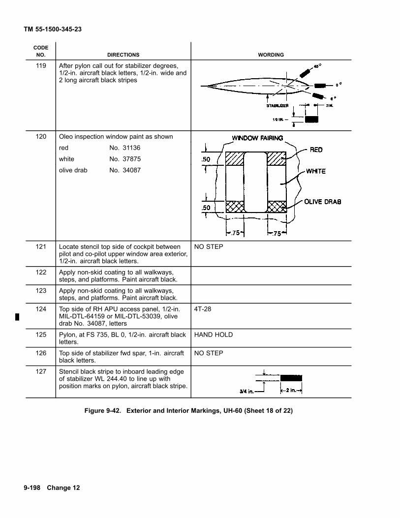
TM 55-1500-345-23
CODENO. DIRECTIONS WORDING
119 After pylon call out for stabilizer degrees,1/2-in. aircraft black letters, 1/2-in. wide and2 long aircraft black stripes
120 Oleo inspection window paint as shown
red No. 31136
white No. 37875
olive drab No. 34087
121 Locate stencil top side of cockpit betweenpilot and co-pilot upper window area exterior,1/2-in. aircraft black letters.
NO STEP
122 Apply non-skid coating to all walkways,steps, and platforms. Paint aircraft black.
123 Apply non-skid coating to all walkways,steps, and platforms. Paint aircraft black.
124 Top side of RH APU access panel, 1/2-in.MIL-DTL-64159 or MIL-DTL-53039, olivedrab No. 34087, letters
4T-28
125 Pylon, at FS 735, BL 0, 1/2-in. aircraft blackletters.
HAND HOLD
126 Top side of stabilizer fwd spar, 1-in. aircraftblack letters.
NO STEP
127 Stencil black stripe to inboard leading edgeof stabilizer WL 244.40 to line up withposition marks on pylon, aircraft black stripe.
Figure 9-42. Exterior and Interior Markings, UH-60 (Sheet 18 of 22)
9-198 Change 12

TM 55-1500-345-23
CODENO. DIRECTIONS WORDING
128 LH and RH exhaust fairing top side, 1/2-in.aircraft black letters.
NO STEP
129 Top side of LH APU access panel, 1/2-in.MIL-DTL-64159 or MIL-DTL-53039, olivedrab, No. 34087, letters.
3T-27
130 Right side of engine nacelle near screen,1/2-in. aircraft black letters.
NO STEP
131 Paint underside of sliding fairing aircraftblack #37038.
132 Inside of cockpit pilot door on vinyl coatednylon pocket, 1/2-in. aircraft white letters.
CHECK LIST DATAAND MAPSTOWAGE
133 RH underside of APU access panel, 1-in.aircraft black letters
NO STEP
134 LH underside of APU access panel, 1-in.aircraft black letters.
NO STEP
**WP1-P2-L3 Date
WP - indicates wash primer used
135 Below gunners window, FS 260, WL220 approximately, black 1/4-in. letters.**Contractor will insert their code.
P - indicates primer used
L - indicates lacquer used (if req’d)
C - indicates coating used (if req’d)
136 Below code 135.
NOTE
Date shown on stencil is date aircraftpaint with MIL-C-46168 paint.
137 Back of Norton Armored crew seat, P/NRA30525-1. First line 1/2-in., second line3/8-in., remaining 1/4-in. orange-yellowletters.
SEAT TILT RELEASE
SEAT TILT RELEASE
Figure 9-42. Exterior and Interior Markings, UH-60 (Sheet 19 of 22)
Change 12 9-199

TM 55-1500-345-23
CODENO. DIRECTIONS WORDING
138 Dot between holes, FS 624, WL 227(approximately), aircraft yellow No. 33538.
• .75 dia
139 Dot between holes, FS 585, WL 227(approximately), aircraft black.
• .75 dia
140 Both sides of aircraft on side ends ofinstrument glare shield, 1/2-in. aircraft whiteletters.
NO HAND HOLD
141 Top of both collective stick cover panels,1/2-in. aircraft white letters.
NO STEP
142 Aircraft battery cover behind copilot’s seat,1/2-in. aircraft black letters.
BATTERY
143 LH and RH side of aircraft on ESSS fixedprovision upper fairing assembly (fwd and aftsections), 1-in. aircraft black letters.
NO STEP
144 LH and RH side of aircraft on ESSS fixedprovision upper fairing assembly platform,1/2-in. aircraft black letters.
HANDHOLD
145 Access panel both RH and LH side of aircraftand above on fuselage air-oil strut, 1/2-in.aircraft black letters.
3T-3B-37
NOTE
Apply only on ESSS provisioned air-craft.
4T-4B-38
3B-39146 Both RH and LH side of aircraft on fairing ataccess to shock strut, 1/2-in. aircraft blackletters. 4B-40
NOTE
Apply only on ESSS provisioned air-craft.
3B-41147 Both RH and LH side of aircraft on ESSSfixed provisions lower fairing assembly (fwd)and another directly above on fuselage (2stencils per side), 1/2-in. aircraft black letters.
4B-43
3B-42148 Both RH and LH side of aircraft on ESSSfixed provisions lower fairing assembly (aft)and another directly above on fuselage (2stencils per side), 1/2-in. aircraft black letters.
4B-44
3T-33149 Both RH and LH side of aircraft on ESSS fixedprovisions upper fairing assembly platformon inboard edge, 1/2-in. MIL-DTL-64159or MIL-DTL-53039, olive drab, No. 34087,letters.
4T-34
9-200 Change 12

TM 55-1500-345-23
CODENO. DIRECTIONS WORDING
150 Top of antenna, 1 in. olive drab letters. NO STEP
151 Top side of VOR/LOC antenna, 1/2 in. olivedrab letters.
6B-6T-19
152 Stencil 2 olive drab, No. 34087, continuousstripes around each main rotor blade. Eachstripe is 1 in. wide and the center of thestripes will be 140.86 inches from the centerof the blade cuff pin holes.
Figure 9-42. Exterior and Interior Markings, UH-60 (Sheet 20 of 22)
Figure 9-42. Exterior and Interior Markings, UH-60 (Sheet 21 of 22)
Change 5 9-200.1

TM 55-1500-345-23
CODENO. DIRECTIONS WORDING
153 Apply non skid coating on LH and RH oilcooler access panels.
154 Apply non skid coating to LH and RH accesspanels.
155 Apply 10 inch wide non skid coating tocontrols/accessories sliding cover.
156 L/H slide of A/C, FS 256 WL 245,approximately, top two lines 1-inch black,#37038, Letters, remainder are 1/2-inchblack, #37038 Letters
U.S. Army (insert model) U.S.A. serial No. (InsertSerial No.) Service this aircraft with MIL-T-83133Grade JP8 Aviation fuel. If not available, refer to TB55-9150-200-24 for alternate fuel.
157 Inside pressure/closed circuit refuelingaccess cover 1/3-in aircraft black letters.
158 Locate stencil at FS 249, WL 219 and FS257, LBL 29. 1/2 in. aircraft black letters
Battery Vent
Figure 9-42. Exterior and Interior Markings, UH-60 (Sheet 22 of 22)
9-200.2 Change 12
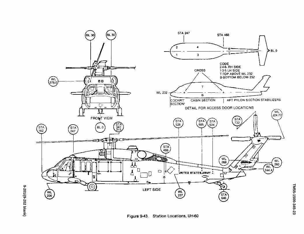
TM55-1500-345-23
9-201/(9-202 blank)


TM 55-1500-345-23
CHAPTER 10FIXED WING AIRCRAFT ILLUSTRATIONS
SECTION I GENERAL
a. The basic external color of the aircraft in thischapter will be insignia white paint. C–12 = Paint #G8022 MFG U.S. paint Federal Standard 595, in accor-dance with MIL-DTL-64159 or MIL-DTL-53039. RC-12= paint # 8228-9316 (MFG Sherwin Williams.)
b. All markings, unless otherwise speci.callynoted in the following figures, will be aircraft black,shade No. 37038 of Federal Standard 595, in accor-dance with MIL-DTL-64159 or MIL-DTL-53039.
c. Unless otherwise specified herein, all letteringwill be standard 50% letters, 0.50 in. high.
d. The following closure areas of C-12 & RC-12aircraft shall be painted the shades indicated, in accor-dance with Federal Standard 595 and MIL-DTL-64159or MIL-DTL-53039.
(1) C-12 and RC-12 landing gear, wheels, in-side of landing gear doors and wheel wells insignia whitepaint # G8022 US Paint.
e. Deleted
Change 12 10-1

TM55
-150
0-34
5-23
SEC
TIO
NII
C12
AN
DR
C-1
2IL
LUST
RAT
ION
S
Figu
re10
-1.
Exte
rior
Mar
king
s,C
-12
(She
et1
of22
)
10-2
Cha
nge
9

PAINT # G-8022INSIGNIA WHITE ONLY
36
26
PAINT VERTICAL LUG RED
59
1
10
UNITED STATES OF AMERICA
14
DETAIL B
67 890
LEFT SIDE VIEW
Figure 10-1. Exterior Markings, C-12 (Sheet 2 of 22)
10
1512
68
4
5
3
GLOSS BLACK PAINT NO. G2017
PAINT # G-8022INSIGNIA WHITE ONLY
20.0
2.0
1.5
TM 55-1500-345-23
Change 9 10-3

INSIGNIA WHITE
PAINT # G-8022
40
15
4
15
C-12
41
29
27
34
2832
30
54
33
3
3134
30
29
28
3
31
34
30
29
INSIGNIA WHITE
PAINT # G-8022
54
3
3
30
32
34
29
28
33
TOP VIEW
Figure 10-1. Exterior Markings, C-12 (Sheet 3 of 22)
PAINT # G-8022INSIGNIA WHITE
TM 5
5-15
00-3
45-2
3
10-4
C
hang
e 9
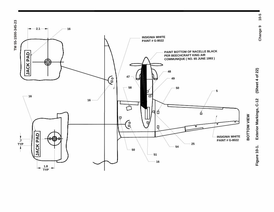
BO
TT
OM
VIE
W
Fig
ure
10
-1.
Ex
teri
or
Ma
rkin
gs
, C
-12
(S
he
et
4 o
f 2
2)
INSIGNIA WHITE
PAINT # G-8022
550
2554
48
49
50
58
16
JA
CK
PA
D
JA
CK
PA
D2.1 16
1.8TYP
.7TYP
16
16
47
51
INSIGNIA WHITE
PAINT # G-8022
PAINT BOTTOM OF NACELLE BLACK
PER BEECHCRAFT KING AIR
COMMUNIQUE ( NO. 65 JUNE 1993 )
TM 5
5-15
00-3
45-2
3
Cha
nge
9
10-
5

25
Figure 10-1. Exterior Markings, C-12 (Sheet 5 of 22)
3.00
35
17
353
1111
23
VIEW
3.00 INSIGNIA WHITE
PAINT # G-8022
VIEWPER BEECHCRAFT KING AIR
200 / 300 / B300 COMMUNIQUE
No. 65 JUNE 93 INSIGNIA WHITE
PAINT # G-8022
52
38
WHITE
1.5 (BLACK)
INSIGNIA WHITE
PAINT # G-8022
24
52INSIGNIA WHITE
PAINT # G-8022
24
PLANE OF PROPELLER
C-1222
33
22.00
TM 5
5-15
00-3
45-2
3
10-6
C
hang
e 9

46
RIGHT SIDE VIEW
Figure 10-1. Exterior Markings, RC-12 (Sheet 6 of 22)
WING TIP PODS OMMITTED THIS VIEW FOR CLARITY
307 00 6
RC-12
3
37
42
5
PAINT # 828-9316
EMERGENCYEXIT
PULL HANDLETO RELEASE
19
PUSH INAFTER RELEASE
19
2.0
19
18
2.0
PUSH INAFTER RELEASE
PUSH
15
18
19
12
13
PAINT # 828-9316
3921
TM 55-1500-345-23
Change 9 10-7

8
WL. 120.00
REF
7
WL. 179.00
REF
53
10
3
6
5
4
RC-121
10
C
US ARMY
C
30 700
2
59
14
360 13
1215
PAINT VERTICAL LUG RED
26
36
50.5±1.0
1.2
20.0
2.0
LEFT SIDE VIEW
Figure 10-1. Exterior Markings, RC-1 (Sheet 7 of 22)
W ING TIP PODS OMITTED THIS VIEW FOR CLARITY
TM 5
5-15
00-3
45-2
3
10-8
C
hang
e 9

2957
56
4443
45
40
15
4
15
RC-12
41
29
27
34
2831
30
54
33
3
3234
30
29
28
3
32
34
30
PAINT # 828-9316
54
3
3
30
31
34
29
28
55
33
TOP VIEWFigure 10-1. Exterior Markings, C-12 (Sheet 8 of 22)
PAINT # 828-9316
PAINT # 828-9316
TM 55-1500-345-23
Change 9 10-9

51
47
16
16
.7TYP
1.8TYP
162.1
JA
CK
PA
D
JA
CK
PA
D
16
58
50
49
48
5425
505
PAINT # 828-9316
BO
TT
OM
VIE
W
F ig
ure
10
-1.
E
xte
rio
r M
ark
ing
s,
RC
-12
(
Sh
ee
t 9
of
22
)
TM 5
5-15
00-3
45-2
3
10-1
0
Cha
nge
9

RC-12 ONLYANTI-STATIC
PAINT # 828-9316 22 RC-1252
PLANE OF PROPELLER 24
24
VIEW
38
52
23
3.00
VIEW
PAINT # 828-9316
1111
17
353
35
3.00
FRONT VIEW
Figure 10-1. Exterior Markings, RC-12 (Sheet 10 of 22)
25
TM 55-1500-345-23
Change 9 10-11

UP
PE
RW
ING
AT
TA
CH
FIT
TIN
GS
WING ATTACH FITTINGS, LEFT HAND SHOWN, RIGHT HAND OPPOSITE, FITTING COVERS OMITTED. Figure 10-1. Exterior Markings, C-12 (Sheet 11 of 22)
DETAIL A:
LUBRICATED BOLTS
SEE MAINT. MANUALFOR TORQUE VALUES
WARNINGLUBRICATED BOLTS
SEE MAINT. MANUALFOR TORQUE VALUES
WARNING
WARNING
C REAR SPAR, REF.L
LUBRICATED BOLTS
SEE MAINT. MANUALFOR TORQUE VALUES
C REAR SPAR, REF.L
LO
WE
RW
ING
AT
TA
CH
FIT
TIN
GS
TO INSTALL DECAL ON WING ATTACHFITTINGS, CUT DECAL ON DOTTED LINES.SAND WING ATTACH FITTINGS LIGHTLYIN REQUIRED AREAS ( DO NOT REMOVEPRIMER). WASH AREA WITH MEK, APPLYDECAL AND SEAL THE EDGES.
C FRONT SPAR, REF.L
TM 55-1500-345-23
10-12 Change 9

LEVELPOINT
DETAIL C Figure 10-1. Exterior Markings, C-12 (Sheet 12 of 22)
WL90.00REF
LEVELPOINT
31.0
1.5TYP
STA278.50REF
DETAIL B
3
INSIGNIA WHITEPAINT # G-8022
67 890
INSIGNIA WHITE ONLYPAINT # G-8022
INSIGNIA WHITE ONLYPAINT # G-8022
WL. 179.00REF
1.0
1.5 (BLACK)
1.5
50.5±1.0
TM 55-1500-345-23
Change 9 10-13

DETAIL E Figure 10-1. Exterior Markings, C-12 (Sheet 13 of 22)
INSIGNIA WHITE ONLYPAINT # G-8022
INSIGNIA WHITEPAINT # G-8022 GLOSS BLACK
US PAINT # G-2017
1.5
TM 55-1500-345-23
10-14 Change 9

DETAIL F
Ffigure 10-1. Exterior Markings, RC-12 (Sheet 14 of 22)
LEVELPOINT
31.00
2.00
1.0
LEVELPOINT
RC-12
F.S.309.25REF
W.L.120.00REF
TM 55-1500-345-23
Change 9 10-15

Left side of fuselage on entrance air step door, adjacent to handle. 1/2-in. MIL-C-46168, aircraft black letters.
PUSH BUTTONAND TURN HANDLE
TO OPEN
Figure 10-1. Exterior Markings, C-12 / RC-12 (Sheet 15-22)
C-12 both sides of fuselage below static port. Do not paint static port. 1/2-in, black letters. RC-12 1/4-in. aircraft black letters. (Use gloss black paint part number G2017 (MFG U.S. Paint) C-12 only) (Use flat black paint part number G2002 (MFG U.S. Paint) RC-12 only)
Paint windows using 828-9316 paint (MFG Sherwin-Williams), exterior aircraft gray. On RC-12 aircraft with cabin windows (D, H).
7
8
9
6
Left side of fuselage aft of cabin door, 1/2-in. aircraft black letters.
RC-12 both sides of fuselage, aft of cabin door. Aircraft black letters. (Using flat black paint part number G2002 (MFG US Paint) RC-12 only)
C-12 both sides of ventral fin and bottom center of each outboard wing panel, 1/2-in. black letters. RC-12, 1/2-in. aircraft black letters. (Use gloss black paint part number G2017 (MFG U.S. Paint) C-12 only) (Use flat black paint part number G2002 (MFG U.S. Paint) RC-12 only)
Aircraft data plate located on left side of aft fuselage.
C-12 both sides of ventral fin, center top trailing edge of each aileron and flap, 1/2-in. black letters. Also center on nose cone using 1/2-in. aircraft black letters. RC-12D, 1/2-in. aircraft black letters and MIL-C-46168 aircraft white letters on nose cone. (Use gloss black paint part number G2017 (MFG U.S. Paint) C-12 only) (Use flat black paint part number G2002 (MFG U.S. Paint) RC-12 only) Also RC-12 Forward data link and Aft data link datalink pods.
Both sides of vertical stabilizer. C-12, see Detail B. RC-12 8-in. aircraft black numbers.
5
4
3
2
U.S. ARMY
TIE DOWN
STATIC AIR KEEP CLEAN
NO PUSH
(Radio call numbers)
CODE NO.
1
DIRECTIONS WORDING
FIRE EXTINGUISHER INSIDE
TM 55-1500-345-23
10-16 Change 9
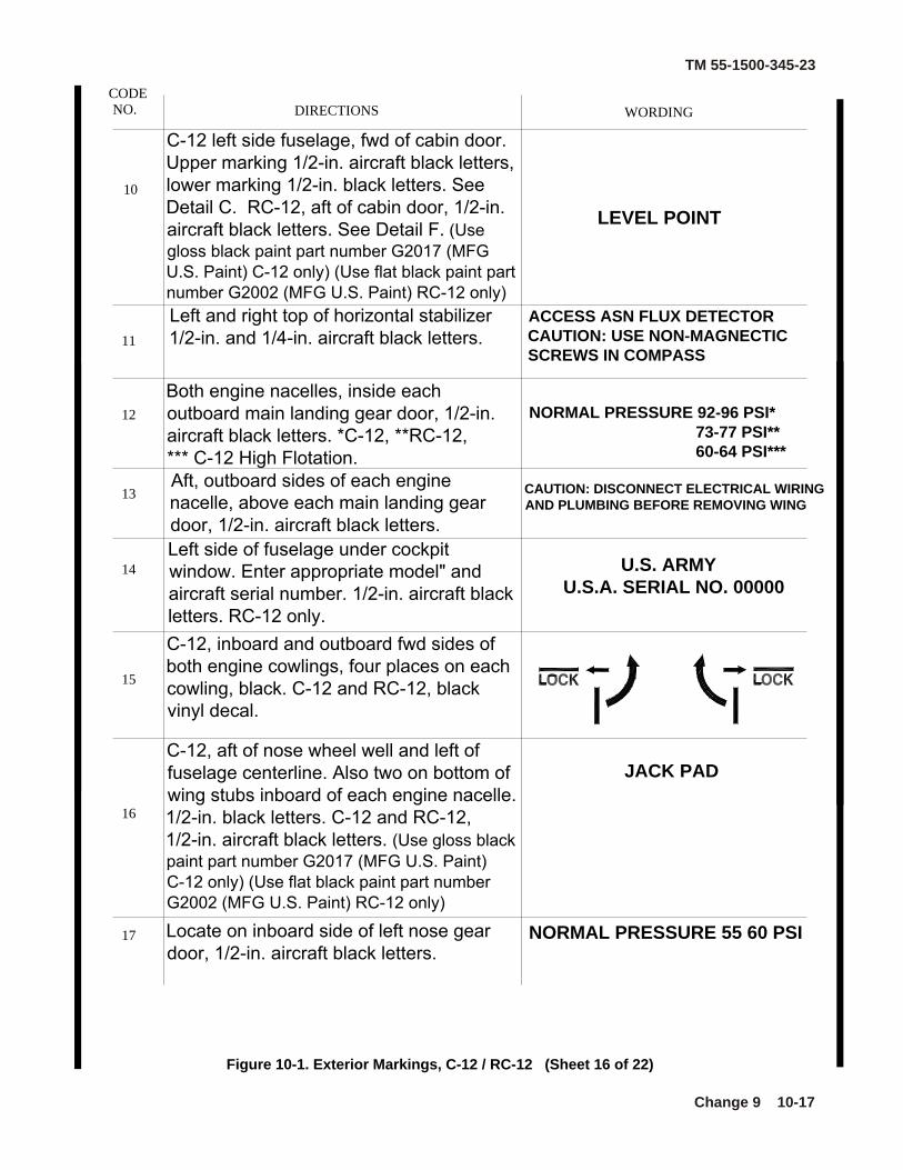
C-12 left side fuselage, fwd of cabin door. Upper marking 1/2-in. aircraft black letters, lower marking 1/2-in. black letters. See Detail C. RC-12, aft of cabin door, 1/2-in. aircraft black letters. See Detail F. (Use gloss black paint part number G2017 (MFG U.S. Paint) C-12 only) (Use flat black paint part number G2002 (MFG U.S. Paint) RC-12 only)
Figure 10-1. Exterior Markings, C-12 / RC-12 (Sheet 16 of 22)
NORMAL PRESSURE 55 60 PSI
U.S. ARMYU.S.A. SERIAL NO. 00000
CAUTION: DISCONNECT ELECTRICAL WIRING AND PLUMBING BEFORE REMOVING WING
NORMAL PRESSURE 92-96 PSI* 73-77 PSI** 60-64 PSI***
C-12, aft of nose wheel well and left of fuselage centerline. Also two on bottom of wing stubs inboard of each engine nacelle. 1/2-in. black letters. C-12 and RC-12, 1/2-in. aircraft black letters. (Use gloss black paint part number G2017 (MFG U.S. Paint) C-12 only) (Use flat black paint part number G2002 (MFG U.S. Paint) RC-12 only)
Locate on inboard side of left nose gear door, 1/2-in. aircraft black letters.
Aft, outboard sides of each engine nacelle, above each main landing gear door, 1/2-in. aircraft black letters.
C-12, inboard and outboard fwd sides of both engine cowlings, four places on each cowling, black. C-12 and RC-12, black vinyl decal.
Left side of fuselage under cockpit window. Enter appropriate model" and aircraft serial number. 1/2-in. aircraft black letters. RC-12 only.
Both engine nacelles, inside each outboard main landing gear door, 1/2-in. aircraft black letters. *C-12, **RC-12,*** C-12 High Flotation.
Left and right top of horizontal stabilizer 1/2-in. and 1/4-in. aircraft black letters.
JACK PAD
WORDINGDIRECTIONSCODE NO.
17
16
15
14
13
11
12
10
LEVEL POINT
ACCESS ASN FLUX DETECTOR CAUTION: USE NON-MAGNECTIC SCREWS IN COMPASS
TM 55-1500-345-23
Change 9 10-17
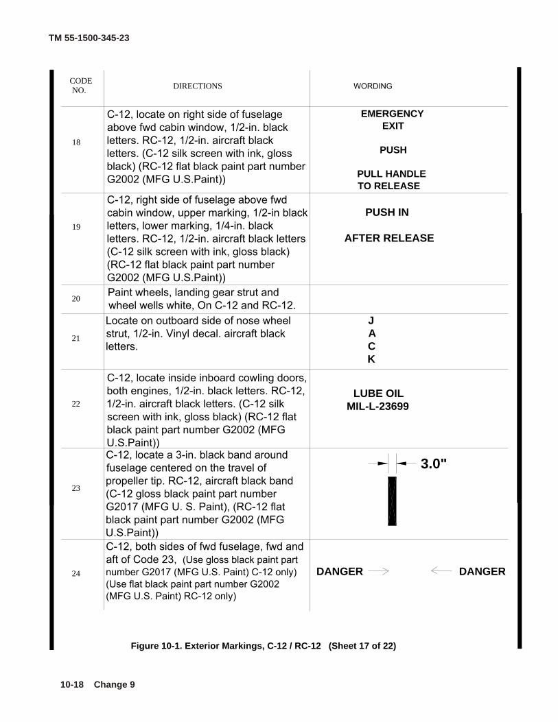
EMERGENCY
EXIT
PUSH
PULL HANDLETO RELEASE
C-12, locate on right side of fuselage above fwd cabin window, 1/2-in. black letters. RC-12, 1/2-in. aircraft black letters. (C-12 silk screen with ink, gloss black) (RC-12 flat black paint part number G2002 (MFG U.S.Paint))
18
DANGER DANGER
Figure 10-1. Exterior Markings, C-12 / RC-12 (Sheet 17 of 22)
C-12, locate a 3-in. black band around fuselage centered on the travel of propeller tip. RC-12, aircraft black band (C-12 gloss black paint part number G2017 (MFG U. S. Paint), (RC-12 flat black paint part number G2002 (MFG U.S.Paint))C-12, both sides of fwd fuselage, fwd and aft of Code 23, (Use gloss black paint part number G2017 (MFG U.S. Paint) C-12 only) (Use flat black paint part number G2002 (MFG U.S. Paint) RC-12 only)
24
23
Paint wheels, landing gear strut and wheel wells white, On C-12 and RC-12.
C-12, locate inside inboard cowling doors, both engines, 1/2-in. black letters. RC-12, 1/2-in. aircraft black letters. (C-12 silk screen with ink, gloss black) (RC-12 flat black paint part number G2002 (MFG U.S.Paint))
Locate on outboard side of nose wheel strut, 1/2-in. Vinyl decal. aircraft black letters.
C-12, right side of fuselage above fwd cabin window, upper marking, 1/2-in black letters, lower marking, 1/4-in. black letters. RC-12, 1/2-in. aircraft black letters(C-12 silk screen with ink, gloss black) (RC-12 flat black paint part number G2002 (MFG U.S.Paint))
20
22
21
19
3.0"
LUBE OILMIL-L-23699
JACK
PUSH IN
AFTER RELEASE
CODE NO.
DIRECTIONS WORDING
TM 55-1500-345-23
10-18 Change 9

C-12, bottom of both wings outboard of nacelles, near wing center lines, 1/2-in. and 1/4-in. black letters. RC-12, 1/2-in. and 1/4-in. aircraft black lettersC-12 black gloss silkscreen ink. Paint number G2017 black gloss (MFG U.S.Paint). RC-12 aircraft black paint number G2002 (MFG U.S.Paint).
CAUTION USE CARE WHEN WASHINGWING TO NOT REMOVE ANTI-CORROSIVE GREASE FROM WING ATTACH BOLT
RC-12 Only, Paint wing tip podassembly, As required using anti-static epoxy paint, Flat black, with a transmissivity range of 0.50 to 75 meg ohms resistance per square specification 528-104 with 910-119 w/catalyst.
C-12, locate near fuselage on top of both wings, 3 places on right wing, 4 places on left wing. 1/2-in black letters. RC-12, 1/2-in. aircraft black letters.C-12 black gloss silkscreen ink. Paint number G2017 black gloss (MFG U.S.Paint). RC-12 aircraft black paint number G2002 (MFG U.S.Paint).
C-12, top right wing, inboard of nacelle, on access cover, 1/2-in. black letters. RC-12, 1/2-in. aircraft black letters.C-12 black gloss silkscreen ink. Paint number G2017 black gloss (MFG U.S.Paint). RC-12 aircraft black paint number G2002 (MFG U.S.Paint).
Figure 10-1. Exterior Markings, C-12 / RC-12 (Sheet 18 of 22)
Paint a black ground symbol, dimensions per MIL-C-83413/9-2.C-12 black gloss silkscreen ink. Paint number G2017 black gloss (MFG U.S.Paint). RC-12 aircraft black paint number G2002 (MFG U.S.Paint).
30
29
Locate on front side of nose landing gear strut, 1/2-in. aircraft black letters.
28
27
26
25
NOSTEP
MICJACK
BATTERY ACCESS
CODE NO. DIRECTIONS WORDING
TM 55-1500-345-23
Change 9 10-19

WORDINGDIRECTIONSCODE NO.
FUEL
MAIN TANK
USE AVIATION KEROSENE OR SEEPILOTS OPERATING MANUAL FOR ALTERNATES. CAPACITY 195 US GALLONS (USABLE 193 US GALLONS)
Antiglare areas shall be painted aircraft black.
C-12, top of both wings beside inboard and outboard fuel caps, 1/2-in. black letters. RC-12, aircraft black letters. (C-12 silk screen gloss black, paint number G2017 (MFG U.S.Paint)) (RC-12 flat black paint part number G2002 (MFG U.S.Paint))
Paint propeller tips white. See chapter 7
32
33
34
35
Locate on front nose gear strut. Aircraft black
C-12, locate on right side of fuselage, below and aft of cargo window, 1/2-in. black letters. RC-12, 1/2-in. aircraft black letters. (C-12 silk screen with ink, paint number G2017 (MFG U.S.Paint)gloss black) (RC-12 flat black paint part number G2002 (MFG U.S.Paint))
36
37
C-12, top of both wings outboard of nacelles, 1/2-in. black letters above 1/4-in. black letters. RC-12, aircraft black letters. (C-12 silk screen gloss black, paint number G2017 (MFG U.S.Paint)) (RC-12 flat black paint part number G2002 (MFG U.S.Paint)). Must be readable from leading edge of wing.
Figure 10-1. Exterior Markings, C-12 / RC-12 (Sheet 19 of 22)
C-12, top of both wings inboard of nacelles, near wing centerline, 1/2-in. black letters above 1/4-in. black letters. RC-12, aircraft black letters. (C-12 silk screen gloss black, paint number G2017 (MFG U.S.Paint)) (RC-12 flat black paint part number G2002 (MFG U.S.Paint))Must be readable from leading edge ofwing.
AUX TANK
PILOTS OPERATING MANUAL FOR ALTERNATES.CAPACITY 79.5 US GALLONS(USABLE 79.0 US GALLONS) WITH WINGS LEVEL
31
TM 55-1500-345-23
10-20 Change 9
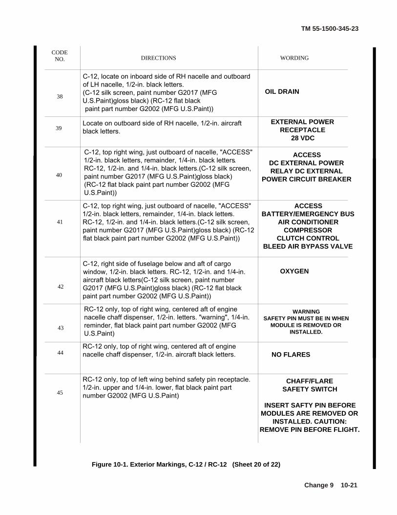
ACCESSDC EXTERNAL POWER RELAY DC EXTERNAL
POWER CIRCUIT BREAKER
C-12, top right wing, just outboard of nacelle, "ACCESS" 1/2-in. black letters, remainder, 1/4-in. black letters. RC-12, 1/2-in. and 1/4-in. black letters.(C-12 silk screen, paint number G2017 (MFG U.S.Paint)gloss black) (RC-12 flat black paint part number G2002 (MFG U.S.Paint))
RC-12 only, top of left wing behind safety pin receptacle. 1/2-in. upper and 1/4-in. lower, flat black paint part number G2002 (MFG U.S.Paint)
RC-12 only, top of right wing, centered aft of engine nacelle chaff dispenser, 1/2-in. aircraft black letters.
RC-12 only, top of right wing, centered aft of engine nacelle chaff dispenser, 1/2-in. letters. "warning", 1/4-in. reminder, flat black paint part number G2002 (MFG U.S.Paint)
C-12, right side of fuselage below and aft of cargo window, 1/2-in. black letters. RC-12, 1/2-in. and 1/4-in. aircraft black letters(C-12 silk screen, paint number G2017 (MFG U.S.Paint)gloss black) (RC-12 flat black paint part number G2002 (MFG U.S.Paint))
C-12, top right wing, just outboard of nacelle, "ACCESS" 1/2-in. black letters, remainder, 1/4-in. black letters. RC-12, 1/2-in. and 1/4-in. black letters.(C-12 silk screen, paint number G2017 (MFG U.S.Paint)gloss black) (RC-12 flat black paint part number G2002 (MFG U.S.Paint))
45
44
43
42
41
CHAFF/FLARESAFETY SWITCH
INSERT SAFTY PIN BEFOREMODULES ARE REMOVED OR
INSTALLED. CAUTION: REMOVE PIN BEFORE FLIGHT.
WARNINGSAFETY PIN MUST BE IN WHEN
MODULE IS REMOVED OR INSTALLED.
ACCESSBATTERY/EMERGENCY BUS
AIR CONDITIONER COMPRESSOR
CLUTCH CONTROLBLEED AIR BYPASS VALVE
NO FLARES
OXYGEN
Locate on outboard side of RH nacelle, 1/2-in. aircraft black letters.
C-12, locate on inboard side of RH nacelle and outboard of LH nacelle, 1/2-in. black letters.(C-12 silk screen, paint number G2017 (MFG U.S.Paint)gloss black) (RC-12 flat black paint part number G2002 (MFG U.S.Paint))
40
39
38
EXTERNAL POWERRECEPTACLE
28 VDC
OIL DRAIN
WORDINGDIRECTIONSCODE NO.
Figure 10-1. Exterior Markings, C-12 / RC-12 (Sheet 20 of 22)
TM 55-1500-345-23
Change 9 10-21

C-12, bottom of both nacelles, 1/2-in. black letters. C-12 and RC-12, 1/2-in. aircraft black letters. (Use silk screen gloss black paint number G2017(MFG U.S.Paint) C-12 only) (Use flat black paint part number G2002 (MFG U.S. Paint) RC-12 only)
ACCESS AC EXTERNAL POWER RELAY AC EXTERNAL POWER CIRCUIT BREAKER
Figure 10-1. Exterior Markings, C-12 / RC-12 (Sheet 21 of 22)
Left side of aircraft aft of cabin door, 1/2-in. aircraft black letters. (Use silk screen gloss black paint number G2017(MFG U.S.Paint) C-12 only) (Use flat black paint part number G2002 (MFG U.S. Paint) RC-12 only)
53
RC-12 only. Left wing just outboard of engine nacelle, near leading edge, 1/2-in. aircraft black letters. (Use flat black paint part number G2002 (MFG U.S. Paint)
Top left side of nose, 1/2-in. aircraft black letters. (Use flat black paint part number G2002 (MFG U.S. Paint)
Locate under access plates on top and bottom of both wings near inboard and outboard wing mating surfaces. "WARNING", 1/2-in. aircraft black letters, remainder, 1/4-in. aircraft black letters. See Detail A. (Use silk screen gloss black paint number G2017(MFG U.S.Paint) C-12 only) (Use flat black paint part number G2002 (MFG U.S. Paint) RC-12 only)
56
55
54
Do not paint these areas.
C-12, bottom aft ends of both engine nacelles, 1/2-in. black letters. RC-12, 1/2-in. aircraft black letters. (Use silk screen gloss black paint number G2017(MFG U.S.Paint) C-12 only) (Use flat black paint part number G2002 (MFG U.S. Paint) RC-12 only)
C-12, bottom of both wings, inboard of nacelles near fuselage, and outboard of nacelles, 1/2-in. black letters. 4 required. RC-12, 1/2-in. aircraft black letters. (Use silk screen gloss black paint number G2017(MFG U.S.Paint) C-12 only) (Use flat black paint part number G2002 (MFG U.S. Paint) RC-12 only)
C-12, bottom of both nacelles, 1/2-in. black letters. RC-12, 1/2-in. aircraft black letters. (Use silk screen gloss black paint number G2017(MFG U.S.Paint) C-12 only) (Use flat black paint part number G2002 (MFG U.S. Paint) RC-12 only)
C-12, bottom of both engine nacelles, 1/2-in. black letters. RC-12, 1/2-in. aircraft black letters. (Use silk screen gloss black paint number G2017(MFG U.S.Paint) C-12 only) (Use flat black paint part number G2002 (MFG U.S. Paint) RC-12 only)
52
51
50
48
49
47
WARNING LUBRICATED BOLTS
SEE MAINT. MANUALFOR TORQUE VALUES
SIGHTGAUGE
PRESSURIZED
GRAVITYLINE DRAIN
FUEL DRAIN
FILTERDRAIN
STRAINER DRAIN
STANDBY PUMP DRAIN
RC-12 only, right side of fuselage centered 1.5 in. above test connector receptacle centerline. 1/2-in. aircraft black letters. (Use flat black paint part number G2002 (MFG U.S. Paint)
46
CODE NO.
DIRECTIONS WORDING
M-130TEST CONNECTOR
TM 55-1500-345-23
10-22 Change 9

TM 55-1500-345-23
CODENO. DESCRIPTION WORDING
57 RC-12 only. Top of left wing just outboard of enginenacelle near wing centerline. 1/2-in. aircraft blackletters. (Use .at black part number G2002 (MFGU.S. Paint ) RC-12 only).
ACCESSINVERTER
115 VAC 3Ø
58 Inboard bottom of left wing near fuselage andleading edge, 1/2-in. aircraft black letters. (Usegloss black paint number G2017 (MFG U.S. Paint)C-12 only) (Use flat black part number G2002 (MFGU.S. Paint ) RC-12 only)
ACCESSBLEED AIR BYPASS VALVE
AVIONIC INVERTER& CONTROL RELAY
59 DELETED
60 RC-12, Bottom, outboard side of left engine nacelle.1/2-in. aircraft black letters. (Use gloss black paintnumber G2017 (MFG U.S. Paint) (Use flat blackpart number G2002 (MFG U.S. Paint ) RC-12 only)
EXTERNAL POWERRECEPTACLE
115 VDC 3Ø, 400 Hz AC
Figure 10-1. Exterior Markings, C-12 (Sheet 22 of 22)
Change 9 10-23

TM 55-1500-345-23
Figure 10-2. Station Diagram, C-12
DELETED pages 10-25 through 10-30
10-24 Change 12

TM 55-1500-345-23
SECTION III DELETED
DELETED pages 10-33 thru 10-54
Change 12 10-31/(10-32 Blank)


TM 55-1500-345-23
SECTION IV DELETED
DELETED pages 10-57 thru 10-64
Change 12 10-55/(10-56 Blank)


TM 55-1500-345-23
SECTION V DELETED
All data on page 10-66 has been deleted.
Change 12 10-65/(10-66 Blank)

TM 55-1500-345-23
SECTION VI DELETED
DELETED pages 10-69 thru 10-76
Change 12 10-67/(10-68 Blank)


TM 55-1500-345-23
SECTION VII DELETED
DELETED pages 10-79 thru 10-88
Change 12 10-77/(10-78 Blank)


TM 55-1500-345-23
SECTION VIII U-21 AND RU-21 ILLUSTRATIONS
1. MIL-DTL-64159 or MIL-DTL-53039, aircraft gray (entire aircraft, exceptwhere noted).
2. MIL-DTL-64159 or MIL-DTL-53039, aircraft Black.
Figure 10-18. Tactical Paint Scheme, RU-21 (Sheet 1 of 2)
Change 12 10-89
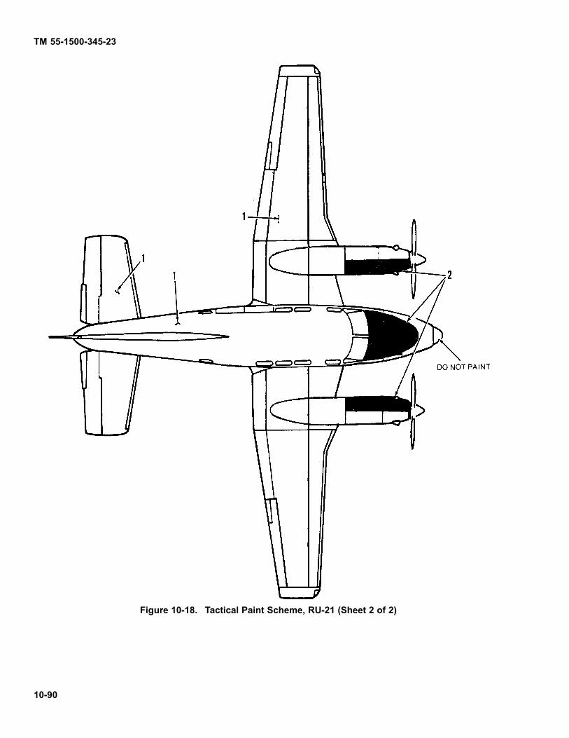
TM 55-1500-345-23
Figure 10-18. Tactical Paint Scheme, RU-21 (Sheet 2 of 2)
10-90

TM 55-1500-345-23
1. MIL-C-83286, gloss olive drab, #14087.
2. MIL-C-83286, gloss white, #17875.
3. MIL-DTL-64159 or MIL-DTL-53039, aircraft black.
Figure 10-19. Non-Tactical Paint Scheme, U-21 (Sheet 1 of 4)
Change 12 10-91
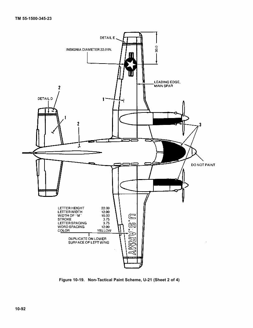
TM 55-1500-345-23
Figure 10-19. Non-Tactical Paint Scheme, U-21 (Sheet 2 of 4)
10-92

TM55-1500-345-23
Figure 10-19. Non-Tactical Paint Scheme. U-21 (Sheet 3 of 4)
10-93
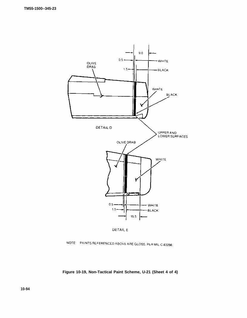
TM55-1500--345-23
Figure 10-19, Non-Tactical Paint Scheme, U-21 (Sheet 4 of 4)
10-94

TM 55-1500-345-23
1. MIL-C-83286, gloss white, #17875.
2. MIL-DTL-64159 or MIL-DTL-53039, aircraft black.
3. MIL-P-21600, .ourescent red-orange, ANA #633 (only whereauthorized.)
Figure 10-20. Non-Tactical, High Visibility Paint Scheme, U-21 (Sheet 1 of 2)
Change 12 10-95

TM 55-1500-345-23
Figure 10-20. Non-Tactical, High Visibility Paint Scheme, U-21 (Sheet 2 of 2)
10-96

TM55-1500-345-23
Figure 10-21. Interior Markings, U-21 and RU-21 (Sheet 1 of 5)
10-97

10-98
Figure 10-21. interior Markings, U-21 and RU-21 (Sheet 2 0f 5)
TM55-1500-345-23

TM55-1500-345-23
CODENO.
1
2
3
4
5
DIRECTIONS
Locate placard top edge of door forward ofSTA 228.75
Locate placard over center of door shaft.Background yellow. Cover placard with 0.12in. acrylic plastic sheet 3.70 in. by 9.0 in.,bevel edges of plastic sheet 45° (See detailA)
Locate placard bottom edge of door forwardof STA 228.75
Locate placards forward of cargo door. Topplacard is aligned with bottom of windowframe, bottom placard is directly below topplacard an above floor (approx.)
Paint inside of right fuselage skin and faceof upholstery panel at the same location asthe exterior markings, STA 254.75 WL 120,0to WL 146.0. Marking will be yellow, shadeNo. 13538
WORDING
Figure 10-21. Interior Markings, U-21 and RU-21 (Sheet 3 of 5)
10-99
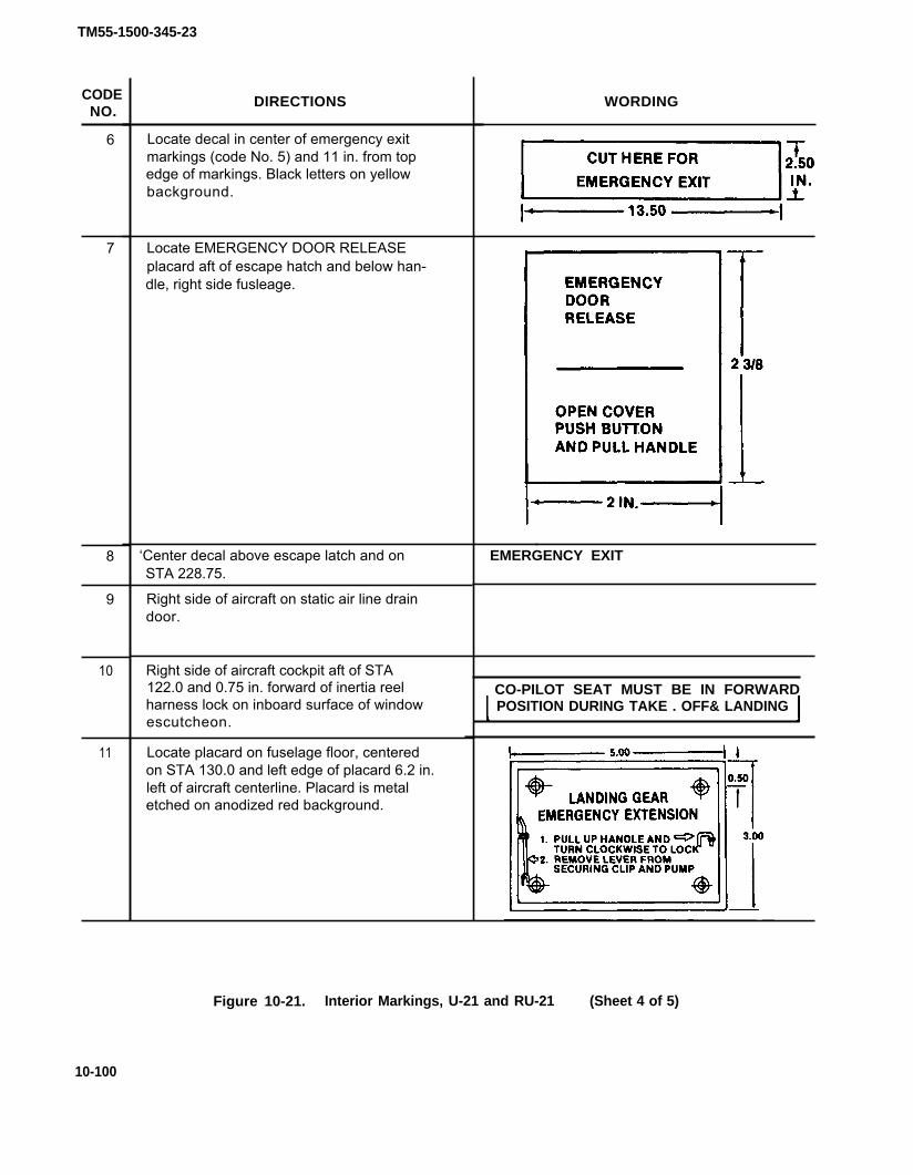
TM55-1500-345-23
CODENO.
6
7
8
9
10
11
DIRECTIONS
Locate decal in center of emergency exitmarkings (code No. 5) and 11 in. from topedge of markings. Black letters on yellowbackground.
Locate EMERGENCY DOOR RELEASEplacard aft of escape hatch and below han-dle, right side fusleage.
‘Center decal above escape latch and onSTA 228.75.
Right side of aircraft on static air line draindoor.
Right side of aircraft cockpit aft of STA122.0 and 0.75 in. forward of inertia reelharness lock on inboard surface of windowescutcheon.
Locate placard on fuselage floor, centeredon STA 130.0 and left edge of placard 6.2 in.left of aircraft centerline. Placard is metaletched on anodized red background.
WORDING
EMERGENCY EXIT
CO-PILOT SEAT MUST BE IN FORWARDPOSITION DURING TAKE . OFF& LANDING
Figure 10-21. Interior Markings, U-21 and RU-21 (Sheet 4 of 5)
10-100
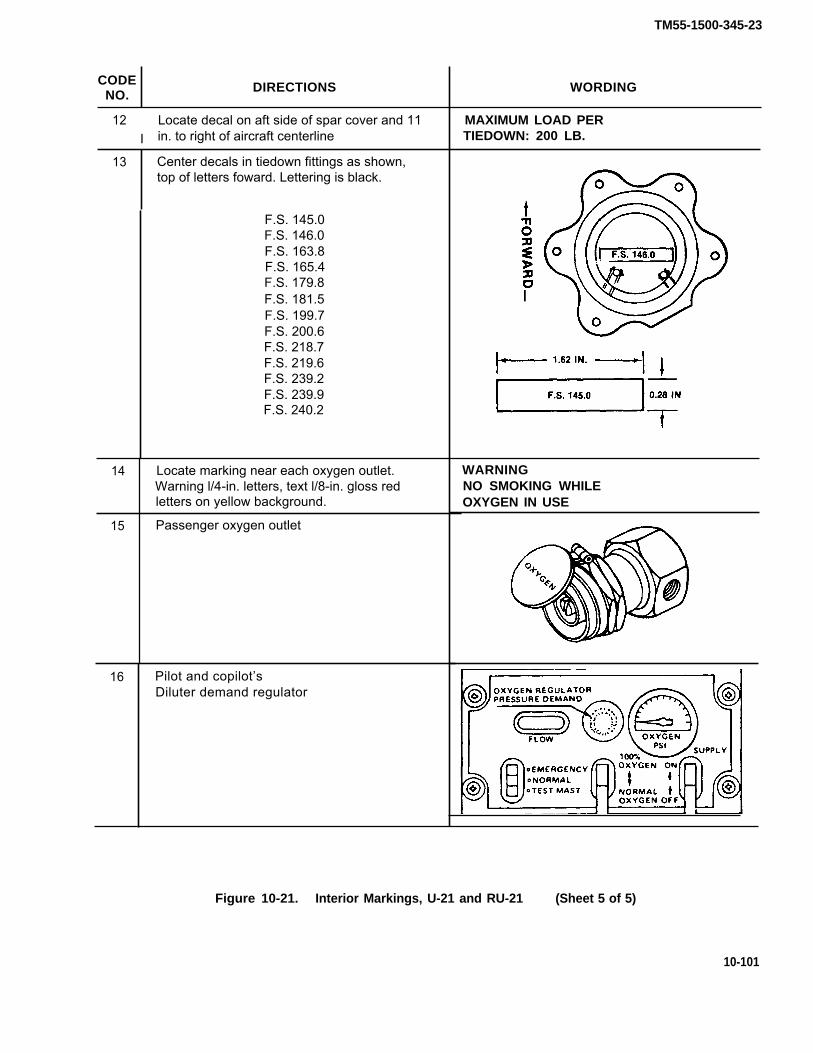
TM55-1500-345-23
CODENO.
DIRECTIONS WORDING
12I
Locate decal on aft side of spar cover and 11in. to right of aircraft centerline
13 Center decals in tiedown fittings as shown,top of letters foward. Lettering is black.
F.S. 145.0F.S. 146.0F.S. 163.8F.S. 165.4F.S. 179.8F.S. 181.5F.S. 199.7F.S. 200.6F.S. 218.7F.S. 219.6F.S. 239.2F.S. 239.9F.S. 240.2
14 Locate marking near each oxygen outlet.Warning l/4-in. letters, text l/8-in. gloss redletters on yellow background.
15 Passenger oxygen outlet
16 Pilot and copilot’sDiluter demand regulator
MAXIMUM LOAD PERTIEDOWN: 200 LB.
WARNINGNO SMOKING WHILEOXYGEN IN USE
Figure 10-21. Interior Markings, U-21 and RU-21 (Sheet 5 of 5)
10-101

TM55-1500-345-23
Figure 10-22. Exterior Markings, U-21 and RU-21 (Sheet 1 of 13)
10-102

TM55-1500-345-23
Figure 10-22. Exterior Markings, U-21 and RU-21 (Sheet 2 of 13)
10-103

TM55-1500-345-23
Figure 10-22 Exterior Markings. U-21 and RU-21 (Sheet 3 of 13)
10-104
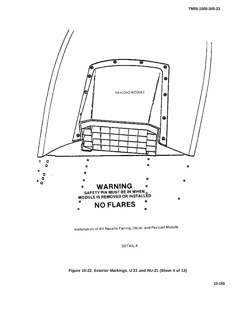
TM55-1500-345-23
Figure 10-22. Exterior Markings. U-21 and RU-21 (Sheet 4 of 13)
10-105

TM55-1500-345-23
10-106
Figure 10-22. Exterior Markings, U-21 and RU-21 (Sheet 5 of 13)

TM55-1500-345-23
CODENO.
2
3
4
5
6
DIRECTIONS
NOTE
Only MIL-C-46168 paints will be used onRU-21 aircraft unless otherwise specified.
Left side of fuselage on entrance air stepdoor, adjacent to handle, 1/2-in. black lettersand arrow. Lines are 1/8 in. wide, arrowhead3/8 in. wide.
RADIO CALL NUMBERSLeft and right side of vertical stabilizer, 6-in.lusterless black numerals, STA 401.00,WL 188.00.
Both sides of ventral fin, center top trailingedge of each aileron, also center on nosecone using black letters.
Aircraft data plate located on left side of air-craft under horizontal stabilizer.
ILeft and right side of aft fuselage and bot-tom center of each outboard wing panel.Black 1/2-in. letters. Top of letters up ortowards spar.
Left and right side of fuselage below staticport, 1/2-in. black letters. Do not paint staticport.
WORDING
NOPUSH
TIE DOWN
STATIC AIRKEEP CLEAN
Figure 10-22. Exterior Markings, U-21 and RU-21 (Sheet 6 of 13)
10-107

TM55-1500-345-23
CODENO.
7
8
13
14
15
DIRECTIONS
U-21, both sides of fuselage, 20 in. dia. basicblue circle, center vertically. Bottom of topstar frame in line with green/white seam.
RU-21, left and right side of fuselage, 6-in.black letters. Center between aft edge ofcabin door and line even with front ofhorizontal stabilizer. Top of letters onWL 120.0.
Left side of fuselage aft of entrance doorframe, 1/2-in. black letters.
Left side of fuselage aft of entrance doorframe, 1/2-in. black letters.
Left side of fuselage aft of entrance doorframe, 1/2-in. black letters.
U-21, top of left wing, bottom of right wing -A 22 in. dia. basic blue circle centered 80 in.inboard of wingtip. Point of star facing fwd.
Left and right side of fuselage on each out-board main gear door, 1/2-in. black letters.
Left and right side of fuselage under wingand on outboard side of each nacelle abovemain landing gear doors. Black 1/2-in.letters.
Left side of fuselage under cockpit window,1 in. black letters and numerals. Enter com-plete model and aircraft serial number.
Left and right side of forward engine cowl-ing. Black 1/8 in. lines and arrow, 1/2-in.black letters, 4 places.
WORDING
(National Star Insignia)
U.S. ARMY
FIRE EXTINGUISHERINSIDE
BATTERY LOCATIONTOP OF RIGHT HAND
WING STUB
LEVELPOINT
(National Star Insignia)
NORMAL PRESSURE 46-50 P.S.I.
CAUTION: DISCONNECT ELECTRICAL WIRINGAND PLUMBING BEFORE REMOVING WING
U.S. ARMY *U.S.A. SERIAL NO. *
(*Indent correct model andserial numbers)
Figure 10-22. Exterior Markings, U-21 and RU-21 (Sheet 7 of 13)
10-108

CODENO.
16
17
19
20
21
22
DIRECTIONS
Aft end of nose wheel well and left offuselage centerline. Two jack pads locatedon bottom of wing stub near rear spar andinboard of each engine nacelle. Black 1/2-in.letters.
Locate on inboard side of left nose geardoor, 1/2-in. black letters.
U-21, paint yellow emergency rescue mark-ings on right side of fuselage at STA 254.75WL 120.0.
RU-21, paint lusterless black.
Right side of fuselage, centered withinemergency rescue markings (code No. 18),1-in. letters, same color shade as markings.
U-21, paint landing gear struts and wheelsolive drab.
RU-21, paint lusterless white.
Locate on outboard side of nose wheel strut.Black 1/2-in. letters, arrow 1 in. long, 1/4 in.shaft and 1/2 in. head.
Locate on inside of left and right cowlingdoors.
U-21, yellow 1/2-in. letters.
RU-21, lusterless black 1/2-in. letters.
TM55-1500-345-23
WORDING
JACK PAD
NORMAL TIRE PRESSURE 50-55 P.S.I.VERY SOFT FIELD TAKEOFF 30-32 P.S.I.
CUT HERE FOREMERGENCY EXIT
LUBE OILMIIL-L-23699 ABOVE -25° FMIL-L-7808 BELOW - 25°F
Figure 10-22. Exterior Markings, U-21 and RU-21 (Sheet 8 of 13)
10-109

TM55 -1500-345-23
CODENO.
23
23
24
24
25
DIRECTIONS
U-21 , paint 3 in. red band, from underside ofblack stripe on left side of fuselage to blackstripe on opposite side inline with propellerplane. Locate PROPELLER placard over redband on both sides of fuselage.
RU-21, Paint 3 in. lusterless black stripe,centered on propeller plane, Top of stripestarts at upper corner of fuselage, 4 in. downfrom skin seam to bottom of nose geardoors. Forward edge of black stripe is ap-proximately 18 1/2 in. aft of nose cone.
U-21, left and right side of forward fuselage,fore and aft of RED/BLACK stripe (code No.23). Word DANGER is 13 1/2 in. down fromtop of stripe and is 1 1/4 in. away from edgeof stripe. Black 2-in. letters, arrow pointstoward stripe and is 4 in. long with 1 in. shaftand 1 1/2 in. arrowhead.
RU-21, left and right side of forwardfuselage, fore and aft of BLACK stripe (codeNo. 23). Word DANGER is 13 1/2 in. downfrom top of stripe and is 1 1/4 in. away fromedge of stripe. Black 2-in. letters, arrowpoints toward stripe and is 4 in. long with 1in. shaft and 1 1/2 in. arrow head.
U-21, outboard of left and right enginenacelles on access doors. Black 1/2-in. let-ters, top of letters toward spar.
WORDING
DANGER
PU-545INVERTER
Figure 10-22. Exterior Markings, U-21 and RU-21 (Sheet 9 of 13)
10-110

TM 55-1500-345-23
CODENO.
25
3 0
RU-21, outboard of left and right engineneedles on access doors. Black lettering,letters towards antenna
Top of nose section forward of’ antiglarepaint. Left and right center wing stub forwardof spar and inboard of nacelles. Black 1/2 in.letters with arrow. Top of letters towards spar.
Top right inboard wing stub On access cover.Black 1/2 in. Ietters, top of letters toward spar.
Top of left and right wing center stub, inboardof needles. Right wing 3 places, left wing 4places, 1/2 in. bIack letters.
Paint a black ground symbol, shade 37038,dimensions per MIL-C-83413/9-2.
DELETE
Figure 10-22.
WORDING
PU-545INVERTER
BATTERYACCESS
NOSTEP
Exterior Makings, U-21 and RU-21 (Sheet 10 of 13)
Change 5 10-111

TM55-1500-345-23
CODENO.
31
32
33
34
35
35
36
DIRECTIONS
Left and right wings, inboard of fuel fillercaps (code No. 30). Black 1/2-in. letters, topof letters towards spar, 2 places.
Top of each engine nacelle, outboard of fuelfiller cap. Black 1/2-in. letters, top of lettersfacing inboard, 2 places.
Antiglare areas. Paint inboard upper 1/4 ofthe left and right nacelles and nose area for-ward of cockpit windshield to STA 53.0.Paint black.
U-21, top of right outboard wing panel on ac-cess door. Yellow 1/2-in. letters top of letterstowards spar.
RU-21, lusterless black 1/2-in. letters,
U-21, propellers shall not be stripped but willbe lightly oversprayed with lusterless black.Do not cover index mark on rear of blade, orserial numbers and data on front of blades.Yellow tip 4-in. wide on front of blade only.For high visibility paint scheme for pro-pellers and spinners, see Chapter 6.
RU-21, propellers shall not be stripped butwill be lightly oversprayed with aircraftblack. Do not cover index mark on rear ofblade, or serial numbers and data on front ofblades. Yellow tip 4 in. wide on front of bladeonly.
Front of nose gear strut. Portect duringpaint stripping. TOW, 1/2-in. letters, re-mainder 1/4-in. with arrows and stripes.Paint black.
WORDING
128 Gallons CapacityMIL-T-5624(JP-4)AVIATION KEROSENECAUTION: NACELLE TANKSMUST BE FULL BEFOREFILLING THIS TANK
57 Gallons CapacityMIL-T-5624(JP-4)AVIATION KEROSENE
ACCESSCN 405/ASN COMPENSATORT-611/ASN INDUCTION COMPASSCAUTION: USE NON-MAGNETICSCREWS IN COMPASS
Figure 10-22. Exterior Markings, U-21 and RU-21
* U . S . GOVERNT PRINTING
(Sheet 11 of 13)
OFFICE: 1994-555-028/0023610-112

TM55-1500-345-23
CODENO. I DIRECTIONS I WORDING
37 U-21, bottom of left and right center wing REMOVE FORstub on access door. Yellow 1/2-in. letters, ACCESS TOtop of letters towards spar. ARC-51
38 Bottom of left and right outboard engine OIL COOLERnacelles. Black 1/2-in. letters. DRAIN
39 U-21, bottom of left and right outboard wingpanels. Locate 1 in. forward of power recep-tacle door. Yellow 1/2-in. letters, top of let-
(Left Wing) A.C.EXTERNALPOWER
ters towards spar(Right Wing) EXTERNAL
RU-21, lusterless black 1/2-in. letters. POWER24 VOLTS
40 Bottom of right wing, outboard of enginenacelle and forward of spar. Black 1/2-in. let-ters, top of letters towards spar.
SEEOPERATOR’SMANUALFORINVERTEROPERATION
Left side of fuselage under modeldesignator (code No. 14) Black 1/4-in. letters.
** Contractor will insert their code.
Stencil below Code 41.NOTE: Date shown on stencil is date air-craft painted with MI L-C-46168 paint.
**WP1-P2-L3 DateWP- indicates wash primer usedP - indicates primer usedL - indicates lacquer used (if req’d)c . indicates coating used (if req’d)
43 U-21, top and bottom of right hand inboard Battery Ventwing aft of battery vent tubes. Paint black.
44 I U-21, leading edge of right inboard wing. I PITOT DrainPaint black.
45 RU-21, center 1 in. over oxygen accesscover. Paint black. OXYGEN
Figure 10-22. Exterior Markings, U-21 and RU-21 (Sheet 12 of 13)
10-113

TM55-1500-345-23
CODENO.
46
47
48
49
DIRECTIONS
RU-21, top right wing, centered aft of enginenacelle, chaff dispensor (see detail A). Paintblack.
RU-21, top right wing, centered aft of enginenacelle, chaff dispensor (see detail A). Paintblack.
RU-21, top of right wing behind safety pinreceptacle (see detail B). Paint black.
RU-21, top right wing behind safety pinreceptacle (see detail B). Paint black.
WORDING
WARNINGSAFETY PIN MUST BE IN WHEN
MODULE IS REMOVED OR INSTALLED
NO FLARES
CHAFF/FLARESAFETY SWITCH
INSERT SAFETY PIN BEFOREMODULES ARE REMOVED ORINSTALLED. CAUTION: REMOVEPIN BEFORE FLIGHT.
M-130TEST CONNECTOR
Figure 10-22. Exterior Markings, U-21 and RU-21 (Sheet 13 of 13)
10-114

Figure 10-23
TM55-1500-345-23
10-115/(10-116 blan
k)

By Order of the Secretary of the Army:
Official:
TM 55-1500-345-23
JOHN A. WICKHAM, JR.General, United States Army
Chief of Staff
R. L. DILWORTHBrigadier General, United States Army
The Adjutant General
DISTRIBUTION:To be distributed in accordance with DA Form 12-31, AVUM and AVIM Requirements
for All Fixed and Rotary Wing Aircraft
*U.S.GOVERNMENT PRINTING OFFICE: 1993 342-421/62103


These are the instructions for sending an electronic 2028The following format must be used if submitting an electronic 2028. The subject line must beexactly the same and all fields must be included; however only the following fields aremandatory: 1, 3, 4, 5, 6, 7, 8, 9, 10, 13, 15, 16, 17, and 27.
From: “Whomever” <[email protected]>To: [email protected]
Subject: DA Form 20281. From: Joe Smith2. Unit: home3. Address: 4300 Park4. City: Hometown5. St: MO6. Zip: 777777. Date Sent: 19--OCT--938. Pub no: 55--2840--229--239. Pub Title: TM10. Publication Date: 04--JUL--8511. Change Number: 712. Submitter Rank: MSG13. Submitter FName: Joe14. Submitter MName: T15. Submitter LName: Smith16. Submitter Phone: 123--123--123417. Problem: 118. Page: 219. Paragraph: 320. Line: 421. NSN: 522. Reference: 623. Figure: 724. Table: 825. Item: 926. Total: 12327. Text:This is the text for the problem below line 27.


RECOMMENDED CHANGES TO PUBLICATIONS AND
BLANK FORMSFor use of this form, see AR 25--30; the proponent agency is ODISC4.
Use Part II (reverse) for Repair Parts and Spe-cial Tool Lists (RPSTL) and Supply Catalogs/Supply Manuals (SC/SM)
DATE
8/30/02
TO: (Forward to proponent of publication or form)(Include ZIP Code)
Commander, U.S. Army Aviation and Missile Command
ATTN: AMSAM--MMC--MA--NP
R eds t one A r s enal, AL. 35898
FROM: (Activity and location)(Include ZIP Code)
MSG, Jane Q. Doe
1234 Any Street
Nowhere Town, AL 34565
PART 1 -- ALL PUBLICATIONS (EXCEPT RPSTL AND SC/SM) AND BLANK FORMS
PUBLICATION/FORM NUMBER
TM 9--1005--433--24DATE
16 Sep 2002TITLE Organizational, Direct Support, And GeneralSupport Maintenance Manual for Machine Gun, .50Caliber M3P and M3P Machine Gun Electrical Test SetUsed On Avenger Air Defense Weapon System
ITEM
NO.
PAGE
NO.
PARA--
GRAPH
LINE
NO. *
FIGURE
NO.
TABLE
NO.RECOMMENDED CHANGES AND REASON
1 WP0005
PG 3
2 Test or Corrective Action column should identify a different WP number.
* Reference to line numbers within the paragraph or subparagraph.
TYPED NAME, GRADE OR TITLE
MSG, Jane Q. Doe, SFC
TELEPHONE EXCHANGE/AUTOVON, PLUS EXTEN-SION
788--1234
SIGNATURE
DA FORM 2028, FEB 74 REPLACES DA FORM 2028, 1 DEC 68, WHICH WILL BE USED. USAPA V3.01

TO: (Forward direct to addressee listed in publication)
Commander, U.S. Army Aviation and Missile Command
ATTN: AMSAM--MMC--MA--NP
R eds t one A r s enal, AL. 35898
FROM: (Activity and location) (Include ZIP Code)
MSG, Jane Q. Doe
1234 Any Street
Nowhere Town, AL 34565
DATE
8/30/02
PART II -- REPAIR PARTS AND SPECIAL TOOL LISTS AND SUPPLY CATALOGS/SUPPLY MANUALS
PUBLICATION NUMBER DATE TITLE
PAGE
NO.
COLM
NO.
LINE
NO.
NATIONAL STOCK
NUMBER
REFERENCE
NO.
FIGURE
NO.
ITEM
NO.
TOTAL NO.OF MAJOR
ITEMSSUPPORTED
RECOMMENDED ACTION
PART III -- REMARKS (Any general remarks or recommendations, or suggestions for improvement of publications and
blank forms. Additional blank sheets may be used if more space is needed.)
TYPED NAME, GRADE OR TITLE
MSG, Jane Q. Doe, SFC
TELEPHONE EXCHANGE/AUTOVON,PLUS EXTENSION
788--1234
SIGNATURE
USAPA V3.01

RECOMMENDED CHANGES TO PUBLICATIONS AND
BLANK FORMSFor use of this form, see AR 25--30; the proponent agency is ODISC4.
Use Part II (reverse) for Repair Parts and Spe-cial Tool Lists (RPSTL) and Supply Catalogs/Supply Manuals (SC/SM)
DATE
TO: (Forward to proponent of publication or form)(Include ZIP Code) FROM: (Activity and location)(Include ZIP Code)
PART 1 -- ALL PUBLICATIONS (EXCEPT RPSTL AND SC/SM) AND BLANK FORMS
PUBLICATION/FORM NUMBER DATE T I T LE
ITEM
NO.
PAGE
NO.
PARA--
GRAPH
LINE
NO. *
FIGURE
NO.
TABLE
NO.RECOMMENDED CHANGES AND REASON
* Reference to line numbers within the paragraph or subparagraph.
TYPED NAME, GRADE OR TITLE TELEPHONE EXCHANGE/AUTOVON, PLUS EXTEN-SION
SIGNATURE
DA FORM 2028, FEB 74 REPLACES DA FORM 2028, 1 DEC 68, WHICH WILL BE USED. USAPA V3.01
Commander, U.S. Army Aviation and Missile CommandATTN: AMSAM-MMC-MA-NPRedstone Arsenal, AL 35898
TM 55-1500-345-23 12 June1986 Painting and Marking of Army Aircraft
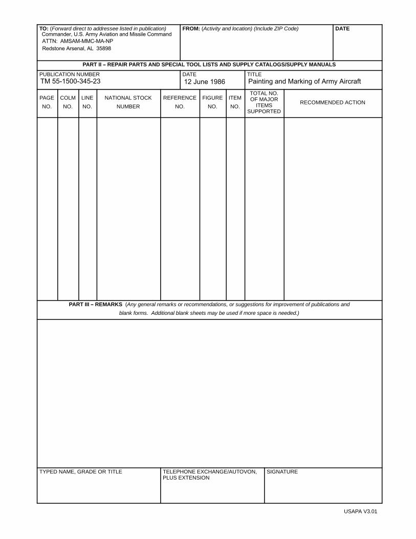
TO: (Forward direct to addressee listed in publication) FROM: (Activity and location) (Include ZIP Code) DATE
PART II -- REPAIR PARTS AND SPECIAL TOOL LISTS AND SUPPLY CATALOGS/SUPPLY MANUALS
PUBLICATION NUMBER DATE TITLE
PAGE
NO.
COLM
NO.
LINE
NO.
NATIONAL STOCK
NUMBER
REFERENCE
NO.
FIGURE
NO.
ITEM
NO.
TOTAL NO.OF MAJOR
ITEMSSUPPORTED
RECOMMENDED ACTION
PART III -- REMARKS (Any general remarks or recommendations, or suggestions for improvement of publications and
blank forms. Additional blank sheets may be used if more space is needed.)
TYPED NAME, GRADE OR TITLE TELEPHONE EXCHANGE/AUTOVON,PLUS EXTENSION
SIGNATURE
USAPA V3.01
Commander, U.S. Army Aviation and Missile CommandATTN: AMSAM-MMC-MA-NPRedstone Arsenal, AL 35898
TM 55-1500-345-23 12 June 1986 Painting and Marking of Army Aircraft

RECOMMENDED CHANGES TO PUBLICATIONS AND
BLANK FORMSFor use of this form, see AR 25--30; the proponent agency is ODISC4.
Use Part II (reverse) for Repair Parts and Spe-cial Tool Lists (RPSTL) and Supply Catalogs/Supply Manuals (SC/SM)
DATE
TO: (Forward to proponent of publication or form)(Include ZIP Code) FROM: (Activity and location)(Include ZIP Code)
PART 1 -- ALL PUBLICATIONS (EXCEPT RPSTL AND SC/SM) AND BLANK FORMS
PUBLICATION/FORM NUMBER DATE T I T LE
ITEM
NO.
PAGE
NO.
PARA--
GRAPH
LINE
NO. *
FIGURE
NO.
TABLE
NO.RECOMMENDED CHANGES AND REASON
* Reference to line numbers within the paragraph or subparagraph.
TYPED NAME, GRADE OR TITLE TELEPHONE EXCHANGE/AUTOVON, PLUS EXTEN-SION
SIGNATURE
DA FORM 2028, FEB 74 REPLACES DA FORM 2028, 1 DEC 68, WHICH WILL BE USED. USAPA V3.01
Commander, U.S. Army Aviation and Missile CommandATTN: AMSAM-MMC-MA-NPRedstone Arsenal, AL 35898
TM 55-1500-345-23 12 June1986 Painting and Marking of Army Aircraft
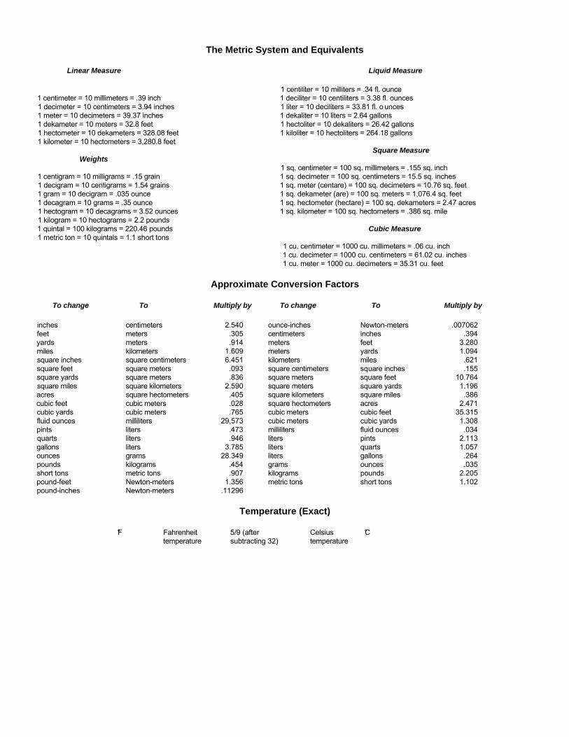
The Metric System and Equivalents
Linear Measure Liquid Measure
1 centiliter = 10 milliters = .34 fl. ounce1 centimeter = 10 millimeters = .39 inch 1 deciliter = 10 centiliters = 3.38 fl. ounces1 decimeter = 10 centimeters = 3.94 inches 1 liter = 10 deciliters = 33.81 fl. o unces1 meter = 10 decimeters = 39.37 inches 1 dekaliter = 10 liters = 2.64 gallons1 dekameter = 10 meters = 32.8 feet 1 hectoliter = 10 dekaliters = 26.42 gallons1 hectometer = 10 dekameters = 328.08 feet 1 kiloliter = 10 hectoliters = 264.18 gallons1 kilometer = 10 hectometers = 3,280.8 feet
Square MeasureWeights
1 sq. centimeter = 100 sq. millimeters = .155 sq. inch1 centigram = 10 milligrams = .15 grain 1 sq. decimeter = 100 sq. centimeters = 15.5 sq. inches1 decigram = 10 centigrams = 1.54 grains 1 sq. meter (centare) = 100 sq. decimeters = 10.76 sq. feet1 gram = 10 decigram = .035 ounce 1 sq. dekameter (are) = 100 sq. meters = 1,076.4 sq. feet1 decagram = 10 grams = .35 ounce 1 sq. hectometer (hectare) = 100 sq. dekameters = 2.47 acres1 hectogram = 10 decagrams = 3.52 ounces 1 sq. kilometer = 100 sq. hectometers = .386 sq. mile1 kilogram = 10 hectograms = 2.2 pounds1 quintal = 100 kilograms = 220.46 pounds Cubic Measure1 metric ton = 10 quintals = 1.1 short tons
1 cu. centimeter = 1000 cu. millimeters = .06 cu. inch1 cu. decimeter = 1000 cu. centimeters = 61.02 cu. inches1 cu. meter = 1000 cu. decimeters = 35.31 cu. feet
Approximate Conversion Factors
To change To Multiply by To change To Multiply by
inches centimeters 2.540 ounce-inches Newton-meters .007062feet meters .305 centimeters inches .394yards meters .914 meters feet 3.280miles kilometers 1.609 meters yards 1.094square inches square centimeters 6.451 kilometers miles .621square feet square meters .093 square centimeters square inches .155square yards square meters .836 square meters square feet 10.764square miles square kilometers 2.590 square meters square yards 1.196acres square hectometers .405 square kilometers square miles .386cubic feet cubic meters .028 square hectometers acres 2.471cubic yards cubic meters .765 cubic meters cubic feet 35.315fluid ounces milliliters 29,573 cubic meters cubic yards 1.308pints liters .473 milliliters fluid ounces .034quarts liters .946 liters pints 2.113gallons liters 3.785 liters quarts 1.057ounces grams 28.349 liters gallons .264pounds kilograms .454 grams ounces .035short tons metric tons .907 kilograms pounds 2.205pound-feet Newton-meters 1.356 metric tons short tons 1.102pound-inches Newton-meters .11296
Temperature (Exact)
°F Fahrenheit 5/9 (after Celsius °Ctemperature subtracting 32) temperature

PIN: 060072-000

This fine document...
Was brought to you by me:
Liberated Manuals -- free army and government manuals
Why do I do it? I am tired of sleazy CD-ROM sellers, who take publicly available information, slap “watermarks” and other junk on it, and sell it. Those masters of search engine manipulation make sure that their sites that sell free information, come up first in search engines. They did not create it... They did not even scan it... Why should they get your money? Why are not letting you give those free manuals to your friends?
I am setting this document FREE. This document was made by the US Government and is NOT protected by Copyright. Feel free to share, republish, sell and so on.
I am not asking you for donations, fees or handouts. If you can, please provide a link to liberatedmanuals.com, so that free manuals come up first in search engines:
<A HREF=http://www.liberatedmanuals.com/>Free Military and Government Manuals</A>
– SincerelyIgor Chudovhttp://igor.chudov.com/
– Chicago Machinery Movers