Page 2 of 36 - Department of Physics · Page 4 of 36 1. Introduction Immediately upon receiving...
35
Page 2 of 36
Transcript of Page 2 of 36 - Department of Physics · Page 4 of 36 1. Introduction Immediately upon receiving...

Page 2 of 36

Page 3 of 36
TABLE OF CONTENTS
1. Introduction 2. Warnings and Cautions 3. General Description 4. Setting up the Thermoelectric Unit 5. Start Up and Operating Procedures 6. Display Messages 7. Changing the Coolant Fluid 8. Recommended Fluids 9. Cleaning the Air Filter 10. General Maintenance 11. Service 12. Customer Service 13. About the Warranty 14. Trouble Shooting Flowcharts 15. Specifications 16. RS232 Interface 17. Equipment/Accessories 18. Warranty Information

Page 4 of 36
1. Introduction
Immediately upon receiving your new ThermoTek chiller (Recirculating Thermoelectric Heating & Cooling System) inspect your unit. If the unit shows shipping damage, contact the transportation company and file a freight damage claim. Retain all packing material and carton until the unit is operated and found to be in good condition (Please see Section 13 About the Warranty for more information). Your chiller has been drained of fluid, but residual fluid may remain. This will not hinder the performance of the unit.
2. Warnings and Precautions
Your system is designed to provide fluid heating and cooling only as specified in this manual. If the system is used in a manner other than as specified, its operation or the safety protection of the system may be impaired. When using your chiller, basic safety precautions should always be followed to reduce the risk of fire, electric shock and personal injury, including the following:
1. Read and follow all instructions and warnings. 2. Use recommended fluids only. 3. Unplug this product from electrical source before cleaning. Do not use liquid cleaners or aerosol
cleaners. Use a soft cloth and warm soapy water only. 4. Do not place this product on an unstable cart, stand or table. The product may fall, causing serious
damage. 5. Slots and openings in the cabinet are provided for ventilation, to protect it from overheating.
These openings must not be blocked or covered. This product should never be placed near or over a radiator, heat register or a built in installation such as a cabinet unless proper ventilation is provided.
6. Never push objects of any kind into this product through cabinet slots as the may touch dangerous voltage points or short out parts that could result in a risk of fire or electric shock. Never spill liquid of any kind into the product.
7. Do not operate at set points below 5°C without a 80% distilled water and %5 inhibited Glycol solution like Dow Frost Prestone™ 5/150 or Prestone LOTOX antifreeze. Prestone™ is trademark of Honeywell International Corporation.
8. Do not operate unit beyond rated capacity. 9. Do not operate the unit above or below 10% of the rated voltage. 10. The unit must be plugged into a properly grounded power source. 11. Do not operate the unit without fluid in the reservoir. 12. Do not operate the unit in a sealed environment. 13. Do not drop the unit or cause impact to the unit. 14. Do not use or maintain the unit outdoors. The systems were not designed to withstand outdoor
weather conditions. 15. Observe warning labels. Never remove the warning labels. 16. Do not operate the unit if it is damaged or leaking fluids. 17. Use only approved fluids. Refer to Recommended Fluids, section 8. Do not use de-ionized water
with this unit. 18. Do not operate unit with damaged or frayed power cords.

Page 5 of 36
19. Always turn the unit OFF and disconnect the power cord from the power source before performing any service, maintenance procedures or moving the unit.
20. Ensure that the chiller is set up according to the instructions before energizing. 3. General Description The T255P is a solid-state thermoelectric heating and cooling system. The unit consists of a pump, fan, electrical circuitry, and a solid-state heat transfer assembly. The T255P maintains a set temperature of the working fluid that is circulated between the thermal management application and itself. Components: High output solid-state heat/cool system Twenty character 2-line alphanumeric LCD module Integral fluid reservoir Circuit breaker Ground terminal Coolant Pump Fans Features: Lightweight, portable package with easy to carry handle User-friendly interface Universal power input Life timer Easy to read LCD display RS-232 interface and computer software (optional) Auto Start Fluid exposed metallic parts are nickel coated Leak free disconnects Memory retention set point

Page 6 of 36
4. Setting up the Thermoelectric Unit 1 Connect the unit to the application using a fluid transport from ThermoTek or hoses using Colder
PLC or PLCD Insert fittings. 2. Keep unit upright and on a level surface. 3. Make sure there is a 6-inch clearance and free path for flow of air entry and
exit around the chiller prior to operation. 4. Check to see if the power switch is in the OFF position. 5. Insert the fluid transport hoses into the machine connections on the lower,
right side of the unit. Hearing a “CLICK” indicates a secure connection. Check labels below the connectors for coolant flow direction.
6. Remove the reservoir cap and add coolant to the reservoir until the fluid level reaches the bottom of the neck. For set temperature below 5°C, see Recommended Fluids (Section 8). Note: When unit is initially powered up it may be necessary to add more fluid to the reservoir.
7. Make sure not to overfill the reservoir. 8. Install the appropriate end of the power cord into the unit. Plug the male end into the appropriate
AC voltage outlet within the specified voltage.
Flow In
Flow Out
Reservoir Cap
RS232 Port
IEC Power Entry Module
Power Switch Fluid Connectors

Page 7 of 36
5. Start up and Operating Procedure 1. Verify that the unit is plugged into the appropriate AC voltage outlet. 2. Turn ON the unit. 3. The ON/OFF switch is located on the right side above the hose connections. 4. When the unit is first powered up, a green back light will be on the display screen. The messages
T255P CHILLER Ver: T255 XXXX appears on the display screen located on the front of the unit. 5. After turning the unit ON you may get a message on the display screen that reads
“!!ALARMS ACTIVE!! LOW COOLANT LEVEL” See setting up the Thermoelectric Unit section:
6. When unit powers up it may be necessary to add more fluid to the reservoir. Press the Run/Standby key to clear the alarm.
7. During the power up sequence, there will be a moment where the keypad is disabled and you will hear the pump being powered up and brought up to speed. Then the fans will be initiated. This sequence will be repeated each time the unit is powered up or taken from standby to operation.
8. The unit will automatically control to 20°C or last set temperature
9. To stop the coolant flow to your application, press the Run/Standby button located on the left side of the display panel. A display message will read “Standby Mode”. The unit has stopped running. Pump will stop and after a few seconds the fans will turn off. To restart the unit press the Run/Standby button.
10. Set the chiller to the desired temperature. To change the set temperature, press the Menu button (lower right) until the display reads Set Temperature.
11. To lower the water temperature, press the Down button on the front panel. To raise the fluid temperature, press the Up button on the front panel. Note: If you hold the button down, the set point will scroll in tenths of degrees and then change to full °C increments.
12. To determine the current water temperature in your application, press the Menu button until the display reads Coolant Temperature.
13. In a Standby Mode press the menu key to display the unit operational hours (Life timer).

Page 8 of 36
6. Display Messages and Alarm Indicators Run/Standby: Standby Mode indicates that the chiller pump is off and the unit is ready for use. Press the pump Run/Standby button to begin heating/cooling the application. Coolant Temperature: Indicates the unit is controlling to set temperature. Set Temperature: Shows the current set temperature. This can be adjusted by pressing the Up and Down buttons to the desired temperature setting. Life Timer: Displays total system hours. !!ALARMS ACTIVE!! LOW COOLANT LEVEL: Immediately return to Standby Mode. Indicates that the water level is low. Resolve by adding coolant to the system. !!ALARMS ACTIVE!! LOW TEMP ALARM: Ambient temperature too low or unit malfunction. Resolve by determining if ambient temperature is below 10°C and/or call ThermoTek service line. !!ALARMS ACTIVE!! HIGH TEMP ALARM: Application load exceeds capacity of unit, ambient temperature too high or unit malfunction. Resolve by determining if application is creating more than 200 Watts of heat, ambient temperature greater than 40°C and/or call ThermoTek service line. !!ALARMS ACTIVE!! TEMP-SENSOR 1 FAIL: Automatic Standby Mode. Unit malfunction. Call ThermoTek service line. FANS WILL CYCLE ON AND OFF: Unable to send error message to display. LCD Display Lock-up: Automatic Standby Mode. Resolve by turning unit power Off/On. 7. Changing the Coolant Fluid 1. Turn the unit OFF and disconnect the power cord. 2. Disconnect the unit from application by depressing thumb-tabs and gently removing the hose
connectors from the unit connectors. 3. Remove the reservoir cap and drain the water by tilting the unit backward.
Once the fluid has completely drained, refill the reservoir with similar fluid until the level reaches the bottom of the neck. Replace the reservoir cap and power cord.
4. Re-install hoses, listening for the click confirming their connection. 5. Return the unit to operation by following the Start Up Operating Procedure.

Page 9 of 36
8. Recommended Coolants 1. Distilled water: For operation from 5°C to 45°C only. Replace monthly to prevent biological
growth. 2. 95% distilled water and 5% alcohol mixture prevents bacterial growth. Replace every 90 days. 3. 80% distilled water and 20% corrosion inhibited Glycol. Use for set temperature below 5°C only.
Recommended: Dow Frost Prestone® 5/150 or Prestone® LOTOX Antifreeze approved for aluminum exposure. Replace every 90 days. Prestone® is a registered trademark of the Honeywell International Corporation.
Note: The above are the only recommended fluids 9. Cleaning the Air Filter 1. Turn the unit OFF and disconnect the power cord. 2. Remove the air filter bracket by twisting the thumbscrew counter-clockwise. 3. Wash the filter with warm soapy water. Rinse and remove all excess water. Ensure the filter is
dry before re-installing. 4. Replace the air filter/bracket and secure with thumbscrew. 5. Return the unit to operation by following the start-up procedure. Note: Clean the filter once a month or on an as needed basis 10. General Maintenance 1. Check the fluid level weekly. 2. Change the fluid in the reservoir as specified in the Recommended Coolants section. 3. Clean the exterior of the unit with a soft cloth and warm soapy water. 4. Do not use abrasive or solvent-based cleaners. 5. Do not immerse the unit in water or any liquid. 6. Keep water away from vents, the power ON/OFF switch and the power cord connection. Note: There are no user serviceable internal parts. To avoid possible electric shock, do not remove the cover. The warranty is voided if the tamper seals are removed. Keep objects that obstruct the airflow away from both the inlet and exhaust fans. 11. Service
ThermoTek recommends you review the troubleshooting flowcharts before calling our customer service support group. If you still need assistance, please call our representatives at 972-874-4949.

Page 10 of 36
12. Customer Service Support
ThermoTek Inc is committed to servicing the customer, both during and after the sale. If you have any questions concerning the operation of your unit please contact our Sales organization at our Flower Mound, Texas facility at 972-874-4949 between 8:00 am and 5:00 pm CST, Monday through Friday or you may email us at www.thermotekusa.com. 13. About the Warranty
All units returned for warranty claims must have a Returned Materials Authorization (herein referred to as RMA) number on the outside of the container. Please call ThermoTek Customer Service at 972-874-4949 for a RMA number. Please refer to the end of this manual for the chiller warranty. Before returning a system to the factory, it must be drained of all fluids and packed in the original packaging. In order to quickly process your warranty repair request, your customer service representative will require the following information about your system:
Model Number Serial Number Description of Problem Contact Name and Phone number
This information is on the serial plate located on the backside of the unit.

Page 11 of 36
14. Trouble Shooting Flowcharts
TROUBLE SHOOTING FLOW CHARTS
No Display
Power cycle theunit
Is displayvisible, unitoperating?
Yes Nuisance trip
No
Has the unit beenpower cycled 3
times?
No Are the fans turningon and off? No Send unit to
ThermoTek
Power cyclethe unit
Is displayvisible? Yes
Resolved
No
Send unit toThermoTek
Yes
Yes

Page 12 of 36
Noisy Display
If within limits
Send toThermoTek
Clean input power
Note: Display may refresh every5 minutes. This is a normal
function.
Check AC Line conditions(100-240 VAC, 50/60 Hz)
Noisy/Foreigncharacters on display
If not within limits

Page 13 of 36
Trips Breaker
Trips Breaker OnChiller
Connect chiller tostandard AC outlet
Does it stilltrip?
Send toThermoTek
Check systempower distribution
Trips ExternalBreaker
No
Verify circuit is notoverloaded.
Connect chiller toanother AC circuit
Does externalbreaker still trip?
Yes
Send back toThermoTek
No Check originalAC circuit
Yes

Page 14 of 36
Keypad notfunctional
Is chiller inRS232 control?
No
Power cycle unit
Is keypadfunctional afterpower cycle?
Normaloperation
Yes
Nuisance trip
Send unit toThermoTek
No
Yes

Page 15 of 36
Leaking Unit
Is leak at quick disconnect?
Yes
Is quick disconnect seatedproperly?
Yes
Call ThermoTek CustomerService
No Reseat quick disconnect untilclick is heard.
No Send unit to Thermotek
Coolant Leak

Page 16 of 36
Unit does not alarm with low or no coolant
Power off, openreservoir cap
Is float sensoron it's shaft?
Send unit toThermoTek
Use small tool todislodge float
sensor
Does unitalarm?
No
Yes
Nuisance trip. Fillreservoir. Power
up.Yes No Send unit to
ThermoTek
Does unitalarm?
No
Check procedure.Drain reservoir perThermoTek Drain
Procedure#200T.14 (1.9.25)
YesSee "Unit
continuous alarmwith coolant".
Does unitalarm w/ no
coolant?No
Send unit toThermoTek
Yes
Add coolant
Does alarmclear? Yes Resolved
No
Send unit toThermoTek

Page 17 of 36
Unit in continuous alarm with coolant
Power off. Open reservoircap.
Use a small tool todislodge float
sensor
Does unit stillalarm?YesSend unit to
ThermoTek
Drain unit perDrain Procedure
#200T.14(1.9.25)
Does unitalarm with no
coolant?
Does alarmclear?
Add coolant Call ThermoTekCustomer Service
Problem solved Send unit toThermoTek
No
NoYes
NoYes

Page 18 of 36
Loop Back Hose See page 28 for more information on a loop back hose.
Stability > +/- 0.1 degree C of setpoint
Note: Stability is defined as +/- 0.1 degree C ofset point, 1/2 gpm flow, constant load, at aconstant ambient (not to exceed system
capacity).
Disconnect fromsystem
Install loopbackhose
Fill reservoir
Power Up
Set setpoint to w/in 1º Cof ambient. Wait 30
minutes for steady state.Re-check stability.
Check quickdisconnects.
Are theyproperlyseated?
Yes CallThermoTek
Is it within +/- 0.1º Cof set point? NoYes
Send toThermoTek for
service
Call ThermoTekfor application
assistance
Is therevigorous flow
agitation?Yes No

Page 19 of 36
Not Heating orCooling/No Temp
Control
No Flow/DiminishedFlow
Not AttainingTemperature
Is set point < 5 ºC?
Yes
Are you using theappropriate fluid?
Yes
No
Isolate the chiller,install loop back
hose, fill reservoir.
The unit has potentiallyfrozen up. See operator
manual forrecommended coolant
Is there vigorousagitation in the
reservoir?
Check QD
Set unit to 40 ºC
Yes
Is QD seatedproperly?
Call ThermoTekCustomerService
Reseat quickdisconnect
Does it reach 40 º Cin 15 minutes?No
Send unit toThermoTek
Set to 15 ºC or 10ºC below ambient,
whichever islowest
Does it reach settemp in 30 minutes?
Yes
NoSend unit toThermoTek
Yes
Is reservoir temp = setpoint +/- 1 ºC? Note:
measured w/ calibratedthermometer
NoSend unit toThermoTek
Chiller isoperational
Yes
Install Checklist:
* Blocked/ restricted coolant flow* Clogged air filter* Blocked air flow* Recirculating air flow* Does operating condition exceed systemcapacity? - see capacity curve.
No
No
No

Page 20 of 36
15. Specifications1 ThermoTek T255P Part Number 0P9T255P10 Dimensions 15.2 inch T x 10.9 inch D x 8 inch W
(386mm T x 277mm D x 203mm W) Ambient Operating Range 10°C to 40°C (50°F to104°F) Indoor Use Only Temperature Range 5°C to 45°C with Coolants Option 1 and 2
-5°C to 45°C with Coolant Option 3 (See Recommended Coolants)
Cooling Capacity 210 watts with set point at ambient temperature Centrifugal Pump 1.0 US gpm (3.86liter/min) open flow water Minimum Flow 0.2 US gpm (0.76 liter/min) Weight 19.4 lbs (8.8kg) Shipping Weight 23.2 lbs (10.5kg) System Fluid Capacity 15 oz (444ml) Power Consumption 625 watts Input Voltage (Nominal) 100-240 VAC 50/60Hz Input Voltage (Max) 85-264 VAC 50/60Hz Pump & Fan Configuration 12V brushless motor Port Coupling Bodies Colder PLC Coupling Inserts Stability ±0.1°C @ 0.6 US gpm flow, constant load at a constant
ambient (not to exceed system capacity) Max Current 7.5 Amps Refrigerant None Heating/Cooling Function Yes RS232 Interface Yes Recommended Coolants Option 1 - Distilled water
Option 2 - 95% distilled water and 5% alcohol mixture prevents bacterial growth Option 3 - 80% distilled water and 20% inhibited Glycol for set temperatures below 5°C
The performance of the chiller is based on Recirculating water with a 0.6 gpm flow. Individual applications will affect chiller performance. ThermoTek must approve all applications. Note 1: Specifications subject to change without notice. ETL tested to UL Standard 2601, CSA 22.2 CE approved with the Medical Device Directive (MDD) IEC 601-1-1, IEC601-1-2 Product Classification: Class 1, Type B Equipment; Continuous Use

Page 21 of 36
0
1
2
3
4
5
6
7
8
0
5
10
15
20
25
0.5 1 1.5 2 2.5 3 3.5
0.2 0.3 0.4 0.5 0.6 0.7 0.8 0.9 1
T255P Typical System Pumping Capacity
Tota
l Hea
d [ft
]
Flow [US gpm]
Tota
l Hea
d [m
]
Flow [liter/min]
Upper Limit
Lower Limit

Page 22 of 36
50
100
150
200
250
300
350
-20 -15 -10 -5 0 5 10 15 20
-30 -20 -10 0 10 20 30
T255P Typical Thermal Capacity
4
6
8
10
12
14
16
18
Coo
ling
Cap
acity
[Btu
/min
]
ΔT [°F]
ΔT [°C]
ΔT = T(fluid out) - T(air in)
Coo
ling
Cap
acity
[W]
Upper Limit
Lower Limit
NOTE: Thermal capacity cited is for distilled water with air filters removed.

Page 23 of 36
16. RS232 Customer Interface 1. General Description
This document specifies an asynchronous, serial communication protocol to allow two devices to exchange data and control functions. These two devices are an IBM compatible Personal Computer (PC).
1.1 Communications Settings
The transmission rate is 9600 Baud, 8 data bits, no parity, 1 stop bit and XON / XOFF flow control.
1.1.1 Connector
The connector is a Male DB9 connector. The RS232 pin assignments are as follows: IBM PC Conditioner Pin Description Description 2 Receive Data Transmit Data 3 Transmit Data Receive Data 5 Signal Ground Signal Ground 1.2 Allowable Characters
Only printable ASCII characters are allowed in this protocol. The exceptions being the XON (11h) and XOFF (13h) characters.
1.3 Communication Startup
To initialize communication or reset communication after a communication time-out, the PC must send a Serial Watchdog Command, SWC. If a valid response is received from the chiller, the PC can consider that communication is established. Refer to section 2.0 for command / response format.
1.3.1 Power -On-Reset
After a power-on-reset, the chiller will perform a self-test and enter the "AUTO START" state. In this state, the chiller will be active, controlling to the setpoint set during the previous operation. In order to initiate communication with the PC, the chiller will issue a XON character every 0.5 seconds, until it receives a SWC command from the PC.
Once a SWC is received and responded to, the chiller will enter the "RUN" Mode. Else it will remain in the "AUTO START" state waiting for a SWC.
1.3.2 Communication Time-out
Once communication is established, the PC must maintain the link by sending the SWC or another valid command every five seconds. The chiller will reset its serial watchdog timer every time a valid command has been received and responded to.

Page 24 of 36
1.3.2.1 Chiller Serial Watchdog Time-out If no communication occurs for a period greater than 10 seconds, then the chiller will take appropriate action, dependant on the state it was in when communications was lost.
Stand By: The chiller will remain in stand by mode and transmit XON characters every 0.5 seconds
until communication is re-established by receiving a SWC or a power-on reset. The unit will return to local (keypad) control, with the display showing “Press Start”.
Chiller Run: The chiller will remain in run mode, but will return to local (keypad) control. XON characters will be transmitted every 0.5 seconds.
1.4 Software Flow Control
The software flow control characters XON and XOFF are defined as 11h and 13h respectively. If the chiller has to temporarily stop the flow of data, it will issue a XOFF, and when it is ready to receive new data again, it will transmit a XON character.
In general the XOFF character will always be sent before the XON character. The only exception to this is, after a power-on reset or loss of communication. Here the chiller will asynchronously issue a XON; as described in section 1.3.1 and 1.3.2.1.
2. Commands
The PC transmits a command to request information or issue command to the chiller. The PC may not send a new command until a response from the previous command has been received. If however, the PC sends a command and a full response has not been received within 3 seconds, a new command may be transmitted.
2.1 Command Format
The command issued by the PC will be in the following format:
soc command code n optional qualifiers checksum cr
Where soc - Start of Command. The command starts with a 2Eh representing an ASCII
period (.). It is one byte in length. command code - a single byte ASCII code (refer to section 3). n optional qualifiers - each qualifier consists of a one to three ASCII bytes for additional
command information.. checksum - two ASCII hexadecimal bytes representing the least significant 8 bits of the
sum of all preceding bytes of the command starting with soc. cr - ASCII carriage return 0Dh
Page 25 of 36
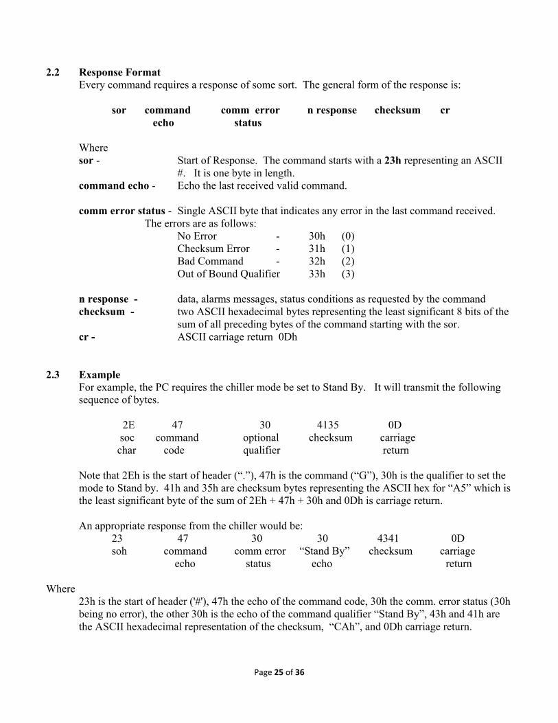
2.2 Response Format Every command requires a response of some sort. The general form of the response is:
sor command comm error n response checksum cr
echo status
Where sor - Start of Response. The command starts with a 23h representing an ASCII
#. It is one byte in length. command echo - Echo the last received valid command.
comm error status - Single ASCII byte that indicates any error in the last command received.
The errors are as follows: No Error - 30h (0) Checksum Error - 31h (1) Bad Command - 32h (2) Out of Bound Qualifier 33h (3)
n response - data, alarms messages, status conditions as requested by the command checksum - two ASCII hexadecimal bytes representing the least significant 8 bits of the
sum of all preceding bytes of the command starting with the sor. cr - ASCII carriage return 0Dh
2.3 Example
For example, the PC requires the chiller mode be set to Stand By. It will transmit the following sequence of bytes.
2E 47 30 4135 0D soc command optional checksum carriage char code qualifier return
Note that 2Eh is the start of header (“.”), 47h is the command (“G”), 30h is the qualifier to set the mode to Stand by. 41h and 35h are checksum bytes representing the ASCII hex for “A5” which is the least significant byte of the sum of 2Eh + 47h + 30h and 0Dh is carriage return.
An appropriate response from the chiller would be:
23 47 30 30 4341 0D soh command comm error “Stand By” checksum carriage echo status echo return Where
23h is the start of header ('#'), 47h the echo of the command code, 30h the comm. error status (30h being no error), the other 30h is the echo of the command qualifier “Stand By”, 43h and 41h are the ASCII hexadecimal representation of the checksum, “CAh”, and 0Dh carriage return.

Page 26 of 36
2.4 Serial Watchdog Command and Response Format The serial watchdog command has a unique format. The command is in the form:
soc command code checksum cr
Where soc Start of Command. The command starts with a 2Eh representing an ASCII
period. It is one byte in length
command code The serial watchdog command is a single byte ASCII code 55h. This represents an ASCII U.
checksum Two ASCII hexadecimal bytes representing the least significant 8 bits of the
sum of all preceding bytes of the command starting with soc.
cr- ASCII carriage return 0Dh
If the chiller received a valid command will issue a response. The response is in the form: sor command comm error n response checksum cr
echo status Where
sor Start of Response. The command starts with a 23h representing an ASCII #. It is one byte in length.
command echo The chiller echo’s the last received command to which it is
responding to. For the watchdog it will be an ASCII 55h.
comm error Single ASCII byte that indicates any errors in the last status command received.
n response The response to the serial watchdog command contains the following data.
Chiller Alarm Chiller Dryer
Status Status Status Status
Chiller Single ASCII byte indicates conditioner status. It is Status defined as follows:
Auto Start 30h (0) Stand By 31h (1) Chiller Run 32h (2) Safety Default 33h (3)
Alarm Status Summation Alarm. This byte is set to (1) if any alarm is
active.
No Alarms 30h (0) Alarm ON 31h (1)

Page 27 of 36
Chiller Status Indicates chiller status.
Chiller OFF 30h (0) Chiller ON 31h (1)
Dryer Status Indicates dryer status. Dryer OFF 30h (0) Dryer ON 31h (1)
checksum Two ASCII hexadecimal bytes representing the least significant 8 bits of the sum of all preceding bytes of the command starting with sor.
cr ASCII carriage return 0Dh
2.4.1 Example The PC would issue the following command: 2E 55 3833 0D soc command checksum cr
The chiller would issue a response similar to: 23 55 30 32 30 31 31 3643 0D
sor command No comm. Chiller No Chiller Dryer Check cr echo error RUN Alarms ON ON sum

Page 28 of 36
3. List of Commands This Table describes the list of commands allowed to interact with the chiller
ASCII Char Command PC Option PC Request Chiller Option Chiller Response
47 G Mode Select 0. Stand By 1. Run Mode
2E 47 30 4135 0D 2E 47 31 4136 0D
23 47 30 30 4341 0D 23 47 30 31 4342 0D
48 H Read Memory 0. Temp & Max Power Setpoint
2E 48 30 4136 0D
23 48 30 30 sf st st st d mp mp mp ck ck 0D
49 I Read Manifold Temp 2E 49 3737 0D
23 49 30 sf mt mt mt mt ck ck 0D
4A J Read Alarm State 2E 4A 3738 0D fs : Float Switch ha : Hi Alarm la : Low Alarm sa : Sensor Alarm pa : EEPROM Fail wa : Watch dog
23 4A 30 fs ha la sa pa wa ck ck 0D Note: All flags are either 0 (ASCII 30) or 1 (ASCII 31). Zero indicates normal condition and a one indicates an alarm. Check flag to identify nature of the alarm
4B K 4C L 4D M Set Stabilized Temp 2E 4D sf st st st ck ck
0D 23 4D 30 sf st st st ck ck 0D
4E N 4F O External Temp Sense
Mode 0. Internal 1. External
2E 4F 30 4144 0D 2E 4F 31 4145 0D
23 4F 30 30 4432 0D 23 4F 30 31 4433 0D
50 P 51 Q 52 R 53 S 55 U Serial Watchdog 2E 55 3833 0D md: mode status
as: alarm status cs: chiller status ds: dryer status
23 55 30 md as cs ds ck ck 0D
Page 29 of 36
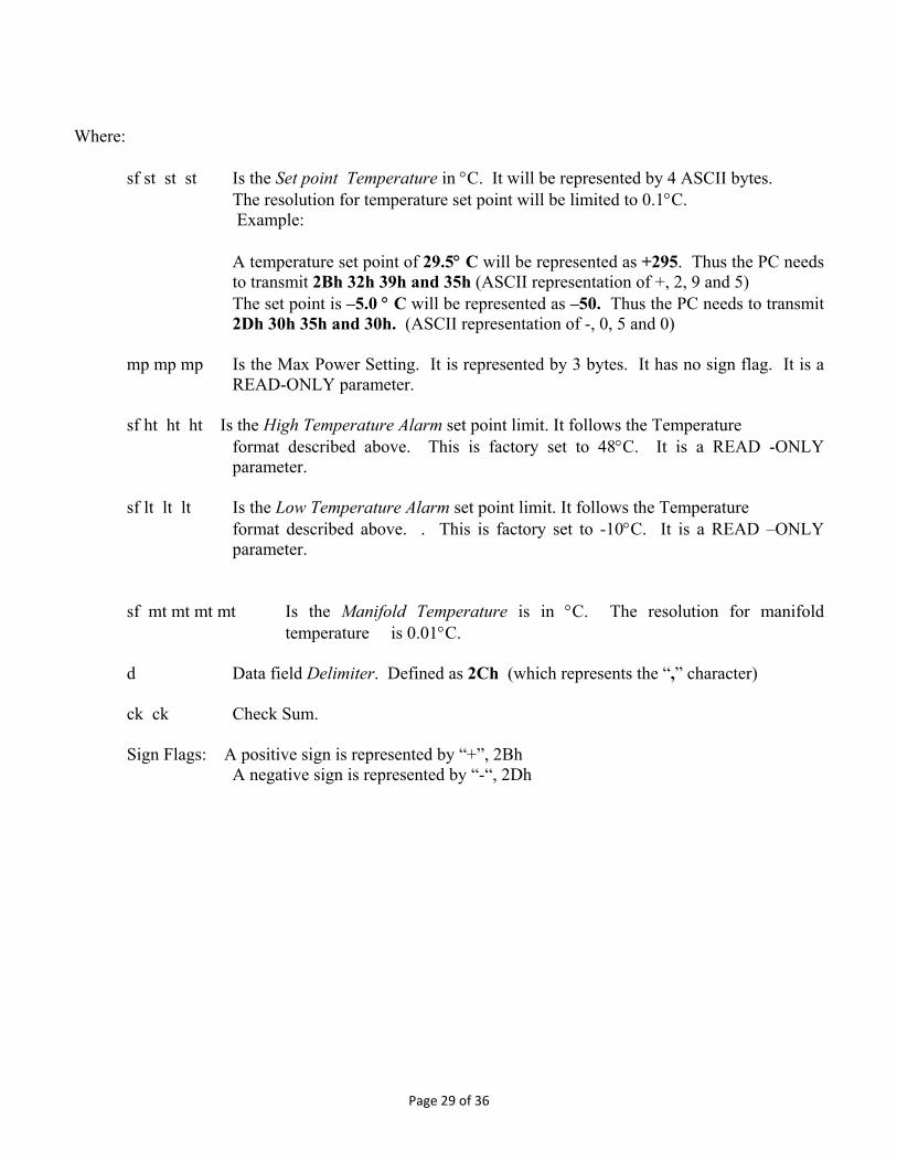
Where: sf st st st Is the Set point Temperature in °C. It will be represented by 4 ASCII bytes.
The resolution for temperature set point will be limited to 0.1°C. Example:
A temperature set point of 29.5° C will be represented as +295. Thus the PC needs to transmit 2Bh 32h 39h and 35h (ASCII representation of +, 2, 9 and 5) The set point is –5.0 ° C will be represented as –50. Thus the PC needs to transmit 2Dh 30h 35h and 30h. (ASCII representation of -, 0, 5 and 0)
mp mp mp Is the Max Power Setting. It is represented by 3 bytes. It has no sign flag. It is a
READ-ONLY parameter.
sf ht ht ht Is the High Temperature Alarm set point limit. It follows the Temperature format described above. This is factory set to 48°C. It is a READ -ONLY parameter.
sf lt lt lt Is the Low Temperature Alarm set point limit. It follows the Temperature
format described above. . This is factory set to -10°C. It is a READ –ONLY parameter.
sf mt mt mt mt Is the Manifold Temperature is in °C. The resolution for manifold temperature is 0.01°C.
d Data field Delimiter. Defined as 2Ch (which represents the “,” character) ck ck Check Sum. Sign Flags: A positive sign is represented by “+”, 2Bh A negative sign is represented by “-“, 2Dh
Page 30 of 36
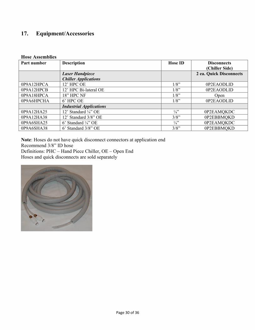
17. Equipment/Accessories
Hose Assemblies
Note: Hoses do not have quick disconnect connectors at application end Recommend 3/8” ID hose Definitions: PHC – Hand Piece Chiller, OE – Open End Hoses and quick disconnects are sold separately
Part number Description Hose ID Disconnects (Chiller Side)
Laser Handpiece Chiller Applications
2 ea. Quick Disconnects
0P9A12HPCA 12’ HPC OE 1/8” 0P2EAODLID 0P9A12HPCB 12’ HPC Bi-lateral OE 1/8” 0P2EAODLID 0P9A18HPCA 18” HPC NF 1/8” Open 0P9A6HPCHA 6’ HPC OE 1/8” 0P2EAODLID Industrial Applications 0P9A12HA25 12’ Standard ¼” OE ¼” 0P2EAMQKDC 0P9A12HA38 12’ Standard 3/8” OE 3/8” 0P2EBBMQKD 0P9A6SHA25 6’ Standard ¼” OE ¼” 0P2EAMQKDC 0P9A6SHA38 6’ Standard 3/8” OE 3/8” 0P2EBBMQKD

Page 31 of 36
Quick Disconnects (Material is polypropylene unless exception noted)
Part Number Description 0P2EQDFBAF 1/8” barb x 1/8” flow female 0P2EAODLID 1/8” barb x 1/8” flow male 0P2EAAFQDC ¼” barb x ¼” flow female 0P2EAMQKDC ¼” barb x ¼” flow male 0P2EBBFQKD 3/8” barb x 1/4” flow female 0P2EBBMQKD 3/8” barb x ¼” flow male 0P2E100412 Disconnect, QK Female 1/4M NPT
Boxes/Foam
Air Filter
Power Cords
Part number Description 0P2HCPFBP0 T255P Foam 0P2H151217 T255P Box
Part number Description 0P2CT255AF Filter, Air, T255 Natural Fiber
Part number Description 0P3C12MGCP Power Cord, US, 13A/110VAC Med Grade 0P3C25010A Power Cord, Euro, 250V/10A

Page 32 of 36
Loop Back Hose: To assemble the loop back hose, you will need two (2) 3/8”barb x ¼” Flow male Disconnects, P/N 0P2EBBMQKD, and a minimum of 6 inches of ¼ ID Nylon Tubing. Insert the threaded ends of P/N 0P2EBBMQKD into each end of the nylon tube. ThermoTek supplies two (2) Disconnects P/N 0P2EBBMQKD with each new system. Please contact Customer Service to purchase additional connectors. The ¼” ID Nylon tube can be purchased at most hardware stores.
P/N: 0P2E100412 P/N: 0P2EBBMQKD
¼ ID Nylon Tubing

Page 33 of 36

Page 34 of 36

Page 35 of 36
18. Warranty Information ThermoTek, Inc. warrants for twelve months from date of manufacture any ThermoTek unit according to the following terms. All parts of the unit manufactured or supplied by ThermoTek shall be free from defects in material and workmanship for a period of one year from the date of manufacture. ThermoTek, Inc. shall repair or exchange the product within the warranty period when the unit has been found in the reasonable judgment of ThermoTek to have defective material or workmanship. The unit must be returned to an authorized ThermoTek Service Center. The buyer shall pay for the expense of returning the unit to the authorized ThermoTek Service Center for warranty service. ThermoTek will pay for the expense of returning the unit back to the buyer. Return units must be in the ThermoTek approved box and packing material to insure safe transport. Removal of the warranty seals or other attempts of servicing the inside of the unit shall void this warranty. The buyer shall be responsible and assessed a fee for test and calibration if no defects are found with the ThermoTek product. In the event that the product or any portion thereof is not installed or used in accordance with the manufacturer's Operating Instructions, any and all warranties either expressed or implied shall be and are hereby voided. Only upon the proper installation and use of the items shall this warranty apply. This warranty does not cover any unit that has been subject to misuse, neglect, or accident. This warranty does not cover any unit that has been altered or modified so as to change its intended use. In addition, this warranty does not extend to repairs made by the use of parts, accessories, or fluids which are either incompatible with the unit or adversely affect its operation, performance, or durability. Because ThermoTek, Inc. constantly provides our customers with the latest technology we reserve the right to change or improve the design of any unit without assuming any obligation to modify any unit previously manufactured. DISCLAIMER THE INFORMATION CONTAINED IN THIS DOCUMENT IS PROVIDED "AS IS". THERMOTEK EXPRESSLY DISCLAIMS ALL INFORMATION INCLUDING, BUT NOT LIMITED TO, EXPRESS AND IMPLIED WARRANTIES OF MERCHANTABILITY, FITNESS FOR A PARTICULAR USE, OR NON-INFRINGEMENT. IN NO EVENT WILL THERMOTEK BE LIABLE FOR ANY DIRECT, INDIRECT, SPECIAL, INCIDENTAL OR CONSEQUENTIAL DAMAGES, INCLUDING LOST PROFITS, LOST BUSINESS OR LOST DATA, RESULTING FROM THE USE OF OR RELIANCE UPON THE INFORMATION, WHETHER OR NOT THERMOTEK HAS BEEN ADVISED OF THE POSSIBILITY OF SUCH DAMAGES. ThermoTek assumes no responsibility for the accuracy or completeness of the information presented which is subject to change without notice. Mention of non-ThermoTek products or services is for information purposes only and constitutes neither an endorsement nor a recommendation.

Page 36 of 36