EECS 262a Advanced Topics in Computer Systems Lecture 6 SOR & LRVM September 17 th , 2012

Page 2 November 2008 - TD 262a OPERATING MANUAL –SEAGUARD® Platform
AANDERAA DATA INSTRUMENTS
1st Edition 26 October 2006
2nd Edition 05 March 2007
3de Edition 30 September 2007
4th Edition 05 November 2007
5th Edition 23 January 2008
6th Edition 15 September 2008
7th Edition 21 November 2008
© Copyright: Aanderaa Data Instruments AS
Contact information:
Aanderaa Data Instruments AS
PO BOX 34, Slåtthaug
5851 Bergen, NORWAY
Visiting address:
Nesttunbrekken 97
5221 Nesttun, Norway
TEL: +47 55 604800
FAX: +47 55 604801
E-MAIL: [email protected]
WEB: http://www.aadi.no

November 2008 - TD 262a OPERATING MANUAL –SEAGUARD® Platform Page 3
Reliable solutions
Table of Contents
INTRODUCTION.......................................................................................................................... 6
Purpose and scope....................................................................................................................................6 Applicable Documents ........................................................................................................................6 Abbreviations.......................................................................................................................................6
Front view of the SEAGUARD® ................................................................................................... 8
Side/Rear view of the SEAGUARD® ............................................................................................ 9
CHAPTER 1 Description ............................................................................................................. 10
The SEAGUARD® Instrument ..............................................................................................................10 Real-Time Output (Licensed Feature) ...................................................................................................11 Instrument and Sensors ..........................................................................................................................11
Symbols .............................................................................................................................................12 Internal Sensors......................................................................................................................................12
System Parameters.............................................................................................................................13 Analog Sensors (Licensed Feature) ...................................................................................................13
CHAPTER 2 The SEAGUARD® Platform.................................................................................. 14
Connection between the SEAGUARD® Instrument and a local PC......................................................14
CHAPTER 3 Preparing the Instrument for a Deployment........................................................... 16
Keyboard................................................................................................................................................16 SEAGUARD® Start Menu .....................................................................................................................16 Sensor Identification ..............................................................................................................................17 System Configuration ............................................................................................................................18 Deployment Settings ..............................................................................................................................20
Site Information (Platform) ...............................................................................................................21 Time between records (Recorder) .....................................................................................................22 Fixed Time Interval (Recorder) ........................................................................................................22 Advanced Recording Sequence (Recorder)......................................................................................23 Advanced Recording Sequence – for set up of timing sequences (Recorder) ...................................24 Enable/Disable Nodes for a Deployment (Recorder) ........................................................................25 Storage Manager................................................................................................................................25 Real-Time Output (Communication Server) .....................................................................................26
Recorder Panel .......................................................................................................................................26 Sensor Sampling ................................................................................................................................29 Start Recording..................................................................................................................................30
CHAPTER 4 Administrative Tools.............................................................................................. 32
User Maintenance ..................................................................................................................................32 Platform .............................................................................................................................................33 Recorder ............................................................................................................................................34 Communication Server ......................................................................................................................34 Configure Analog sensor Properties..................................................................................................35

Page 4 November 2008 - TD 262a OPERATING MANUAL –SEAGUARD® Platform
AANDERAA DATA INSTRUMENTS
Sensor Monitor.......................................................................................................................................38 Calculations of Power and Storage Capacity .........................................................................................39
Define/Add new Battery details.........................................................................................................41 Import/Export Configuration..................................................................................................................42 Instrument Identification ........................................................................................................................46 Display off..............................................................................................................................................47 Command prompt...................................................................................................................................48 Licensed Features –Option Modules......................................................................................................48
CHAPTER 5 Control Panel ......................................................................................................... 51
Battery Capacity ................................................................................................................................51 Flash Registry ....................................................................................................................................52 SD Storage .........................................................................................................................................52 S-Flash ...............................................................................................................................................53
CHAPTER 6 SEAGUARD Studio .............................................................................................. 54
Import Data ............................................................................................................................................54 Customising Graphs ...............................................................................................................................55 Full Screen View....................................................................................................................................58 Exporting Graphs ...................................................................................................................................58 Export Data ............................................................................................................................................58 Edit listed data........................................................................................................................................59
Splitting one data series into several shorter data series....................................................................60 Setup.......................................................................................................................................................60
CHAPTER 7 Operating Instructions............................................................................................ 62
Preparations for Use...............................................................................................................................62 Illustrations of deployment preparations ...........................................................................................63
Retrieval of the Instrument.....................................................................................................................65 Connection and disconnection of sensors ..............................................................................................66
Procedure for connecting a sensor .....................................................................................................66 Illustration of a sensor connection .....................................................................................................68 Procedure for disconnecting a sensor ................................................................................................71
Battery ....................................................................................................................................................72 Removal and insertion of the Battery ................................................................................................72 Rejuvenating of Lithium batteries .....................................................................................................73
SD card...................................................................................................................................................74
CHAPTER 8 Maintenance........................................................................................................... 75
General ...................................................................................................................................................75 Yearly Maintenance...........................................................................................................................75 Illustrations of Maintenance Procedures............................................................................................76
Factory Service.......................................................................................................................................77 Tools- and Maintenance Kit...................................................................................................................77 Maintenance Kit for SEAGUARD®.......................................................................................................78 Software update of Main Board .............................................................................................................78
Upload SEAGUARD® Image and Update New Registry..................................................................79

November 2008 - TD 262a OPERATING MANUAL –SEAGUARD® Platform Page 5
Reliable solutions
Instructions for Uploading SEAGUARD® Image .............................................................................79 Time settings ..........................................................................................................................................80
Appendix 1 Technical Specifications........................................................................................... 81
SEAGUARD® Platform Specifications ................................................................................................81

Page 6 November 2008 - TD 262a OPERATING MANUAL –SEAGUARD® Platform
AANDERAA DATA INSTRUMENTS
INTRODUCTION
Purpose and scope
This Operating Manual describes the SEAGUARD® Instrument: configuration of the SEAGUARD® Instrument with sensors, Operating Instructions and Maintenance. Further it gives you an introduction to SEAGUARD Studio - how to import and visualise your measured data.
SEAGUARD® is the latest of our oceanographic instruments. It can be used both in the sea and in fresh water. 3 versions are available: SEAGUARD® Light Weight with depth rating of 300m, SEAGUARD® Intermediate Water with a depth rating of 2000m, and finally the 6000m depth version.
The SEAGUARD® instrument consists of a platform with sensors attached to it. AADI sensors are all smart sensors, which are
automatically detected and recognised by the platform when the instrument powers up. Up to 4 analog sensors can be used with the instrument. The SEAGUARD® Platform is adding a correct configuration dialog for the attached sensors.
The most common ways of deploying the instrument is in an ordinary string mooring, in a bottom frame, or mounted underneath a buoy.
SEAGUARD® is a self-recording instrument; data is stored on a Secure Digital card, SD card, for later post-processing and analysis.
Data can be output Real-Time in a non-polled mode.
Applicable Documents
D366 SEAGUARD® Platform Data Sheet B150 SEAGUARD® Concept Brochure Form 135 Instrument Service Order TN262b SEAGUARD® RCM Operating Manual TD 208 Operating Manual for Data Reading Program 5059 TD 267 AADI Real-Time Output Protocol TD 268 AADI Real-Time Data Collector
Abbreviations
ADC Analog to Digital Converter
AiCaP Automated idle lined CANbus based Protocol
ASCII American Standard Code for Information Interchange
CAN Controller Area Network - sometimes referred to as CANbus
DSP Digital Signal Processor
EPROM Erasable Programmable Read Only Memory

November 2008 - TD 262a OPERATING MANUAL –SEAGUARD® Platform Page 7
Reliable solutions
GMT Greenwich Mean Time
GPRS General Packet Radio Service
HUB Connection Point for Network Devices
LCD Liquid Crystal Display
RAM Random Access Memory
ROM Read-Only Memory
RTC Real Time Clock
SD card Secure Digital (Memory) card
SR10 This signal corresponds to the digital signal obtained when the contents of a 10-bit shift register are clocked out in serial format. This signal is used when the parameter to be measured is digital, e.g. a frequency or a number of pulses.
UART Universal Asynchronous Transmitter and Receiver
UNESCO The United Nations Educational, Scientific and Cultural Organization
USB Universal Serial Bus

Page 8 November 2008 - TD 262a OPERATING MANUAL –SEAGUARD® Platform
AANDERAA DATA INSTRUMENTS
Front view of the SEAGUARD®
Electrical terminal
Top-end plate
LCD Display
Stylus
Reset button
SD card
Power button
Boot loader
SD card cover
Figure 0 - 1 Front view of the SEAGUARD® Instrument
November 2008 - TD 262a OPERATING MANUAL –SEAGUARD® Platform Page 9
Reliable solutions
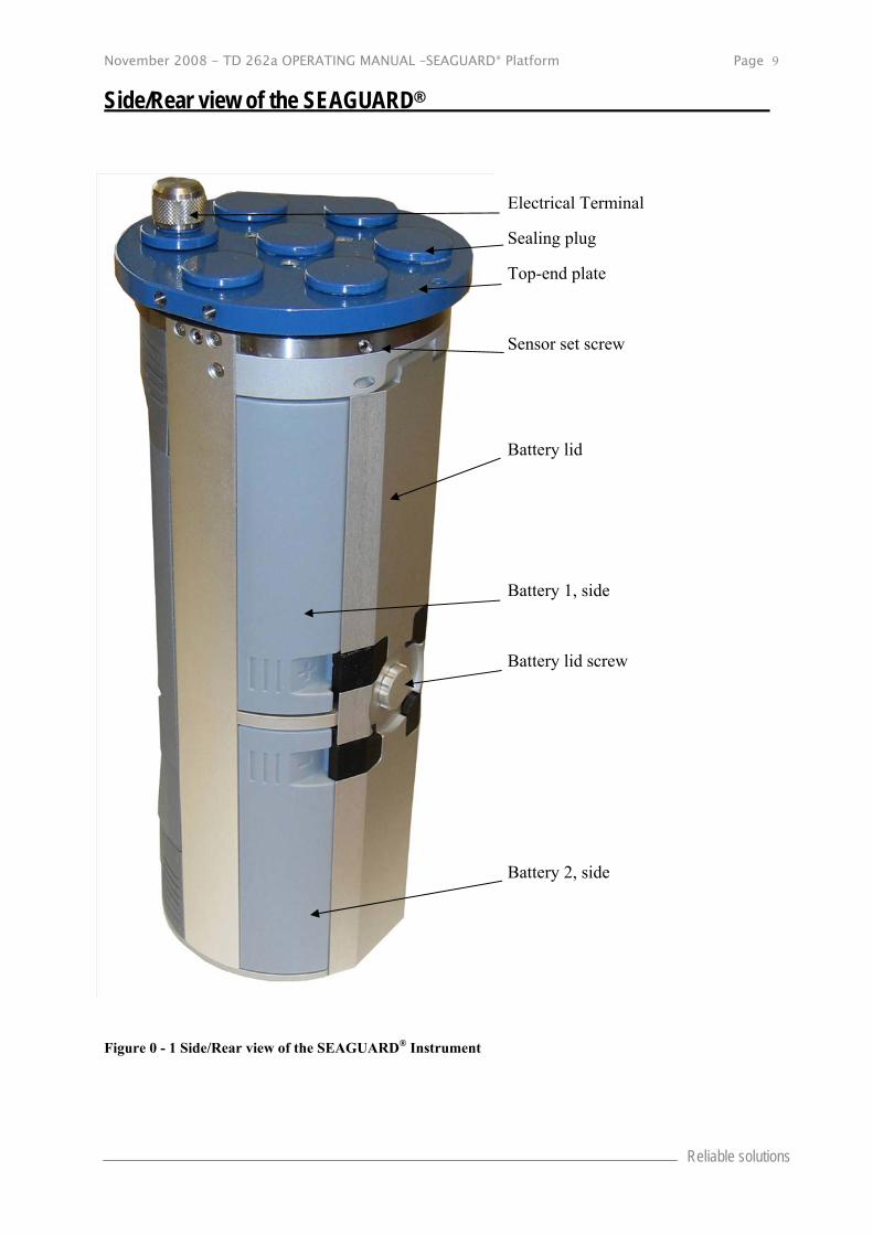
Side/Rear view of the SEAGUARD®
Figure 0 - 1 Side/Rear view of the SEAGUARD® Instrument
Electrical Terminal
Sealing plug
Top-end plate
Sensor set screw
Battery lid
Battery 1, side
Battery lid screw
Battery 2, side
Page 10 November 2008 - TD 262a OPERATING MANUAL –SEAGUARD® Platform
AANDERAA DATA INSTRUMENTS
CHAPTER 1 Description
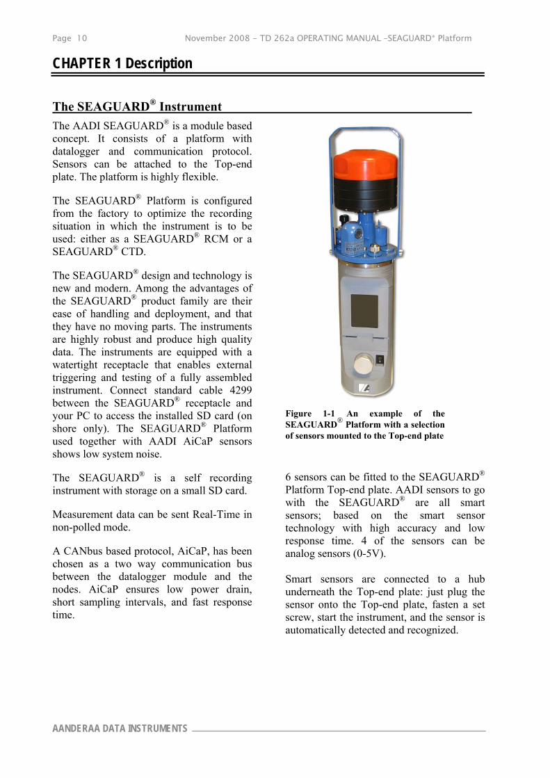
The SEAGUARD® Instrument
The AADI SEAGUARD® is a module based concept. It consists of a platform with datalogger and communication protocol. Sensors can be attached to the Top-end plate. The platform is highly flexible.
The SEAGUARD® Platform is configured from the factory to optimize the recording situation in which the instrument is to be used: either as a SEAGUARD® RCM or a SEAGUARD® CTD.
The SEAGUARD® design and technology is new and modern. Among the advantages of the SEAGUARD® product family are their ease of handling and deployment, and that they have no moving parts. The instruments are highly robust and produce high quality data. The instruments are equipped with a watertight receptacle that enables external triggering and testing of a fully assembled instrument. Connect standard cable 4299 between the SEAGUARD® receptacle and your PC to access the installed SD card (on shore only). The SEAGUARD® Platform used together with AADI AiCaP sensors shows low system noise.
The SEAGUARD® is a self recording instrument with storage on a small SD card.
Measurement data can be sent Real-Time in non-polled mode.
A CANbus based protocol, AiCaP, has been chosen as a two way communication bus between the datalogger module and the nodes. AiCaP ensures low power drain, short sampling intervals, and fast response time.
Figure 1-1 An example of the SEAGUARD® Platform with a selection of sensors mounted to the Top-end plate
6 sensors can be fitted to the SEAGUARD® Platform Top-end plate. AADI sensors to go with the SEAGUARD® are all smart sensors; based on the smart sensor technology with high accuracy and low response time. 4 of the sensors can be analog sensors (0-5V). Smart sensors are connected to a hub underneath the Top-end plate: just plug the sensor onto the Top-end plate, fasten a set screw, start the instrument, and the sensor is automatically detected and recognized.
November 2008 - TD 262a OPERATING MANUAL –SEAGUARD® Platform Page 11
Reliable solutions
Sensors can be connected to the Top-end plate via a cable. Maximum cable length for AiCaP sensors is 6m and the maximum cable length is 5m for analog sensors.
Adaptive software is automatically adding a correct configuration dialog for the new sensor. The SEAGUARD® Platform responsibilities are to collect data from the sensors/nodes.
In the core of the SEAGUARD® is a new data logger based on the Intel PXA 255 embedded ARM processor and the real time operating system Windows CE 5.0. This system topology is not compatible with AADI positive ground based SR10, VR22 and PDC4 format.
A modern Windows based post processing system for PC, SEAGUARD Studio, comes with the SEAGUARD®. SEAGUARD Studio holds the deployment configuration and measurement data lists. SEAGUARD Studio also arranges for export of data and visualisation of the measurements in customised graphs.
Real-Time Output (Licensed Feature) The SEAGUARD® Instrument can output Real-Time data in XML-format over an RS422 transmission line. The Real-Time Output Protocol is described in TD 267 and can be used as a guide to a skilled engineer into creating an application that utilizes the data from the SEAGUARD® Instrument.
Accompanying the Real-Time Output, AADI can supply a Real-Time Collector program for the receiver station for further distribution of data. Refer TD 268 for more information about the Real-Time Collector.
Install the license key in Administrative Tools.
The communication settings for RS422 are found in System Configuration.
The Real-Time Output of data is enabled in the Deployment Settings.
The Recorder Panel provides information about the Real-Time output status (enabled/disabled).
Instrument and Sensors You will find that some menus separate the settings/configurations into two categories: Instrument and Sensors.
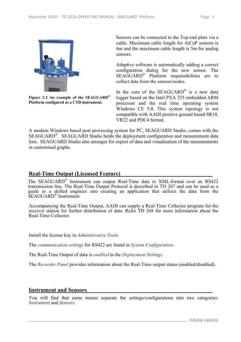
Figure 1-2 An example of the SEAGUARD® Platform configured as a CTD instrument.

Page 12 November 2008 - TD 262a OPERATING MANUAL –SEAGUARD® Platform
AANDERAA DATA INSTRUMENTS
The items in the Instrument category can be Platform, Recording, Storage Manager, and Communication Server.
The items in the Sensor category are Analog Sensors and connected external sensors.
Symbols
Main symbols used in the SEAGUARD display and setup menus.
Platform
Recorder
Storage Manager
Real-Time/Communication Server
System Parameters
Analog Sensors
Sensor
Figure 1-3 Symbols used in SEAGUARD Display and the menus.
Internal Sensors The SEAGUARD® contains two internal sensors, System Parameters and Analog Sensors. The internal sensors are always present in the system.

November 2008 - TD 262a OPERATING MANUAL –SEAGUARD® Platform Page 13
Reliable solutions
System Parameters
The System Parameters measures parameters which can be used for system monitoring and diagnostics. The System Parameters is not configurable.
System Parameters has the following parameters:
Battery Voltage: Monitors the battery voltage during recording. Memory Used: Monitors the use of available system memory during recording. Interval: Monitors the time to next measurement.
Analog Sensors (Licensed Feature)
The Analog Sensors consists of four input channels, each of which can measure 0 to 5V, and are supported with a common 10V power supply output. This enables the user to connect external sensors with analog outputs.
User settings for the analog sensor node are power related: select either continous power to the analog sensors or set a stabilisation time, which tells the instrument to power the analog sensors before each recording (drains less power).
When installing analog sensors to your SEAGUARD® Instrument, you must perform some sensor configurations like sensor/parameter name, engineering units, power drain, calibration coefficients, etc. These sensor settings do not have to be changed between deployments.
Install the license key in Administrative Tools, Option Module, refer CHAPTER 4.
The configuration of the analog sensor is found in Administrative Tools, User Maintenance, refer CHAPTER 4.
In the System Configuration you must remember to enable/disable measurement parameters form the attached analog sensor.
Page 14 November 2008 - TD 262a OPERATING MANUAL –SEAGUARD® Platform
AANDERAA DATA INSTRUMENTS
CHAPTER 2 The SEAGUARD® Platform
Start the instrument by pressing the power button in the front of the instrument. Wait for a few seconds before the LCD display at the front of the instrument is activated.
We recommend that you power the instrument from an AC/DC source when working with the instrument in the office to avoid unnecessary battery drain. Connect the AC/DC power cable 4499 to the electrical terminal on the Top-end plate, refer Figure 2-1 .
Important! Ensure that the protective cap is fitted and tightened to the electrical terminal before deployment.
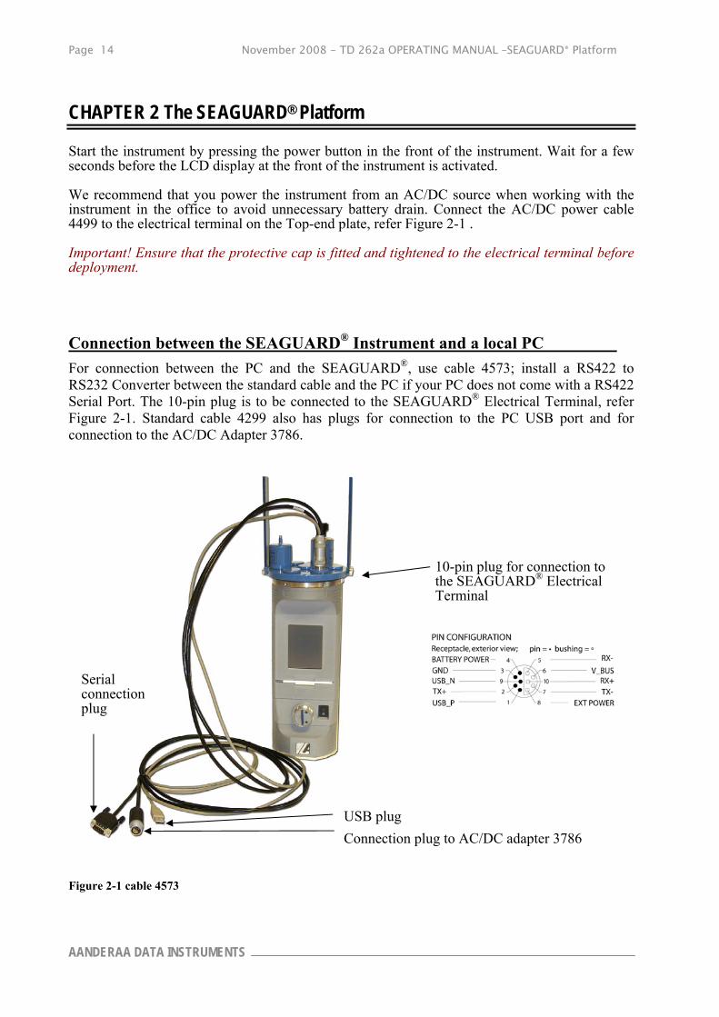
Connection between the SEAGUARD® Instrument and a local PC
For connection between the PC and the SEAGUARD®, use cable 4573; install a RS422 to RS232 Converter between the standard cable and the PC if your PC does not come with a RS422 Serial Port. The 10-pin plug is to be connected to the SEAGUARD® Electrical Terminal, refer Figure 2-1. Standard cable 4299 also has plugs for connection to the PC USB port and for connection to the AC/DC Adapter 3786.
10-pin plug for connection to the SEAGUARD® Electrical Terminal
Figure 2-1 cable 4573
Serial connection plug
USB plug
Connection plug to AC/DC adapter 3786
November 2008 - TD 262a OPERATING MANUAL –SEAGUARD® Platform Page 15
Reliable solutions
When connected to your local PC you are able to make backup of your data by transferring files from the SD card to the PC.
For connection between the Instrument and your local PC: Download and install Microsoft ActiveSync version 4.1 or later; connect the standard connection cable to the instrument’s electrical terminal and the USB end of the cable to the PC. At instrument start up, ActiveSync will respond with a short sound from the PC, and an Icon appears on the Instrument, refer Figure 3-1.

Page 16 November 2008 - TD 262a OPERATING MANUAL –SEAGUARD® Platform
AANDERAA DATA INSTRUMENTS
CHAPTER 3 Preparing the Instrument for a Deployment
Your SEAGUARD® Platform has been configured from the factory to optimize the recording situation in which the instrument is to be used, refer CHAPTER 1.
Before each deployment, you must consider configuration properties that determine how the sensors and the Data logger collect data. Examples of configuration properties are recording interval, calibration coefficients, enabling/disabling of measurement parameters, real-time output etc. During configuration of the Data logger, the Configuration Properties are modified by the user.
This chapter guides you through the SEAGUARD® Menu for preparing the instrument for deployment.
Important! We recommend that you select the Recorder options Allow sleep between recordings and Turn display off if sleep is unavailable, refer CHAPTER 4, Figure 4-5. Refer each sensor manual for power consumption issues.
Note! Some sensors are rated down to 300m and 2000m. Make sure your sensors are rated for the operating depth that you require.
Keyboard
Use the keyboard function to type your configuration on the LCD display, refer Figure 3-1.
Tap the keyboard icon in the bottom left corner to activate the keyboard.
Next, tap the letters one by one to type appropriate names.
Hide the Keyboard function by tapping the Keyboard icon once more.
Icon for Active Sync
SEAGUARD® Start Menu The SEAGUARD® Start Menu holds the key entries for the configuration and use of the instrument.
Figure 3-1 Illustration of Keyboard
November 2008 - TD 262a OPERATING MANUAL –SEAGUARD® Platform Page 17
Reliable solutions
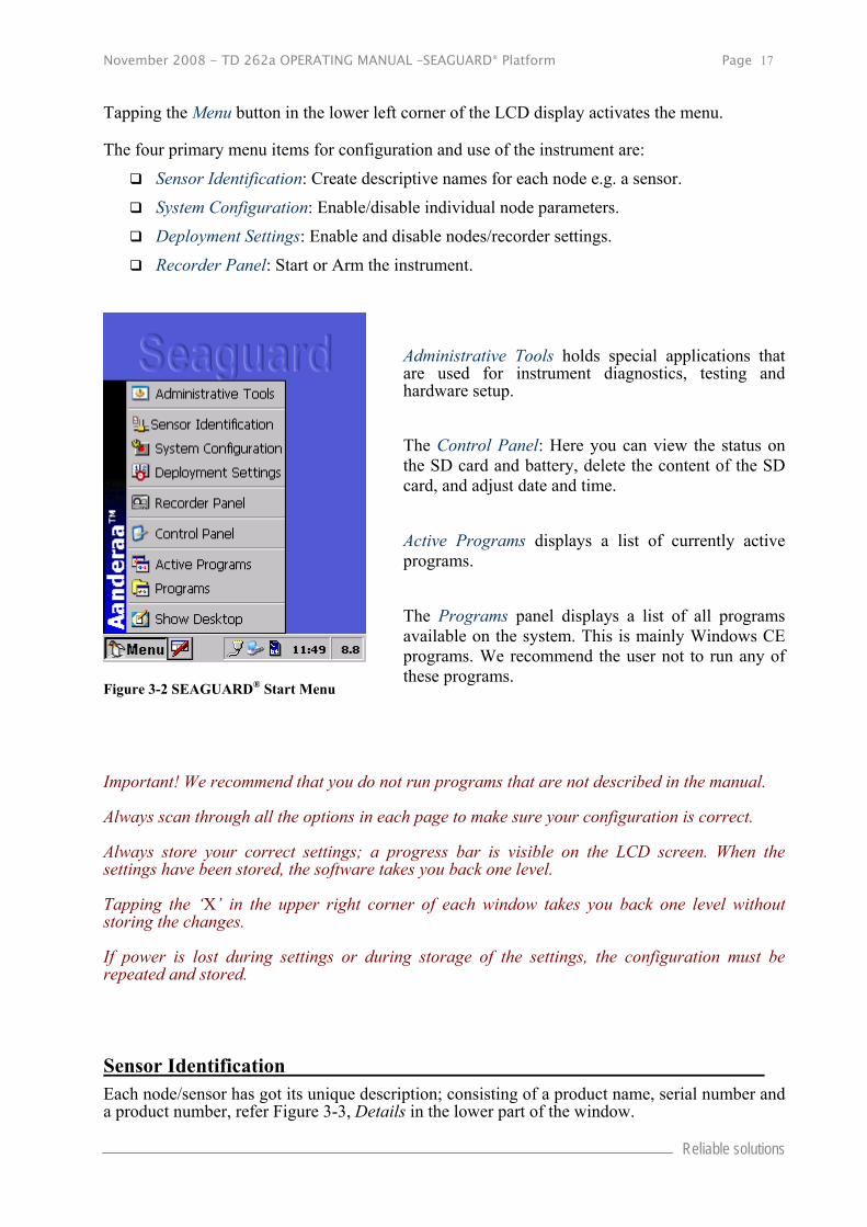
Tapping the Menu button in the lower left corner of the LCD display activates the menu.
The four primary menu items for configuration and use of the instrument are:
Sensor Identification: Create descriptive names for each node e.g. a sensor.
System Configuration: Enable/disable individual node parameters.
Deployment Settings: Enable and disable nodes/recorder settings.
Recorder Panel: Start or Arm the instrument.
Administrative Tools holds special applications that are used for instrument diagnostics, testing and hardware setup.
The Control Panel: Here you can view the status on the SD card and battery, delete the content of the SD card, and adjust date and time.
Active Programs displays a list of currently active programs.
The Programs panel displays a list of all programs available on the system. This is mainly Windows CE programs. We recommend the user not to run any of these programs.
Important! We recommend that you do not run programs that are not described in the manual.
Always scan through all the options in each page to make sure your configuration is correct.
Always store your correct settings; a progress bar is visible on the LCD screen. When the settings have been stored, the software takes you back one level.
Tapping the ‘X’ in the upper right corner of each window takes you back one level without storing the changes.
If power is lost during settings or during storage of the settings, the configuration must be repeated and stored.
Sensor Identification Each node/sensor has got its unique description; consisting of a product name, serial number and a product number, refer Figure 3-3, Details in the lower part of the window.
Figure 3-2 SEAGUARD® Start Menu

Page 18 November 2008 - TD 262a OPERATING MANUAL –SEAGUARD® Platform
AANDERAA DATA INSTRUMENTS
Sensor Identification gives you the possibility to rename the sensor, without changing the original description. You are then able to edit a customised name, which makes it easy for you to recognise it later. The customised sensor name will then be the sensor identity in the configuration until the sensor name is changed.
Tap the Sensor Identification in the SEAGUARD® Start Menu, refer Figure 3-2. The display will show a list of sensors, refer Figure 3-3. System Parameters and Analog Sensors are internal sensors. The other sensors listed are external sensors connected to the SEAGUARD® Instrument.
Select the sensor you want to rename, e.g. Pressure #13, refer Figure 3-3.
Tap the Edit Description button to rename the desired node. Click Save and Exit to store the new name. If you want to rename more than one node, you are able to edit all of them and click Save and Exit after the last editing.
System Configuration In the system configuration you can enable or disable measurement parameters from each sensor.
Open the System Configuration from the SEAGUARD® Start Menu. System Configuration is divided in two categories: Instrument and Sensors. Refer Figure 3-4 and Figure 3-6.
Tap Run Wizard to perform system configuration on all nodes in the category, or select a specific item from the list in the lower part of the window. Tap Configure to enable/disable the specific node properties.
The Instrument configuration holds settings for Real-Time communication with the Instrument, refer Figure 3-5.
The Sensors configuration holds sensor settings. Each sensor has its own set of properties.
Figure 3-3 Sensor Identification
Figure 3-4 System Configuration Menu

November 2008 - TD 262a OPERATING MANUAL –SEAGUARD® Platform Page 19
Reliable solutions
The Communication Server settings for Real-Time communication with the instrument are Baud Rate, Data Bits, Stop Bits, Parity and Flow Control, refer Figure 3-5.
Baud Rate: Select a baud rate in the range 2400 to 115200 (the baud rate must equal the receiver baud rate e.g. the AADI Real-Time Collector).
Data Bits: Set the number of Data Bits to 7 or 8. Set the value to 8 when the receiver is the AADI Real-Time Collector.
Stop Bit: Select between 1, 1.5 and 2 stop bits. Set the value to 1 when the receiver is the AADI Real-Time Collector.
Parity: Select between None, Even and Odd parity. Set the value to None when the receiver is the AADI Real-Time Collector.
Flow Control: Select between None and XonXoff. Set the value to Xon/Xoff when the receiver is the AADI Real-Time Collector.
Note! Each sensor has got a default parameter (in engineering units) which can not be disabled (e.g. raw data measurements necessary to calculate the engineering units). Parameters that are not default can be enabled/disabled.
The property of a sensor is e.g. to enable/disable Raw data.
The property value Yes means enabled, while No means disabled.
The property of the Analog Sensors is to enable/disable measurements parameters from each of the four input channels, refer Figure 3-7.
Note! Refer CHAPTER 4 for configuration of the Analog sensor properties.
Figure 3-5 Communication Setup RS422
Figure 3-6 Sensor Configuration
Page 20 November 2008 - TD 262a OPERATING MANUAL –SEAGUARD® Platform
AANDERAA DATA INSTRUMENTS
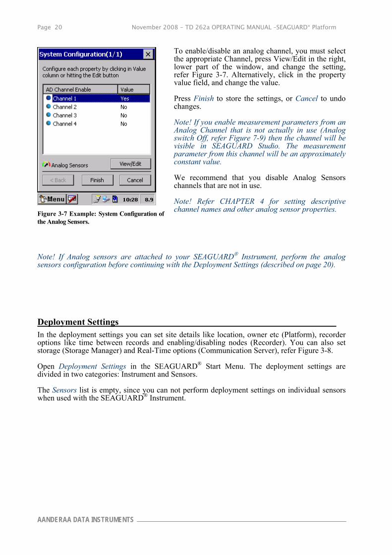
To enable/disable an analog channel, you must select the appropriate Channel, press View/Edit in the right, lower part of the window, and change the setting, refer Figure 3-7. Alternatively, click in the property value field, and change the value.
Press Finish to store the settings, or Cancel to undo changes.
Note! If you enable measurement parameters from an Analog Channel that is not actually in use (Analog switch Off, refer Figure 7-9) then the channel will be visible in SEAGUARD Studio. The measurement parameter from this channel will be an approximately constant value.
We recommend that you disable Analog Sensors channels that are not in use.
Note! Refer CHAPTER 4 for setting descriptive channel names and other analog sensor properties.
Note! If Analog sensors are attached to your SEAGUARD Instrument, perform the analog sensors configuration before continuing with the Deployment Settings (described on page 20).
Deployment Settings In the deployment settings you can set site details like location, owner etc (Platform), recorder options like time between records and enabling/disabling nodes (Recorder). You can also set storage (Storage Manager) and Real-Time options (Communication Server), refer Figure 3-8.
Open Deployment Settings in the SEAGUARD® Start Menu. The deployment settings are divided in two categories: Instrument and Sensors.
The Sensors list is empty, since you can not perform deployment settings on individual sensors when used with the SEAGUARD® Instrument.
Figure 3-7 Example: System Configuration of the Analog Sensors.

November 2008 - TD 262a OPERATING MANUAL –SEAGUARD® Platform Page 21
Reliable solutions
The Instrument list holds settings for the Platform, the Recorder, the Storage Manager and the Communication Server.
You can either be guided through the Deployment setup via Run Wizard, or you can choose to configure each specific item.
For configuring one specific item, without going through the wizard, select the item from the list in the lower part of the window, refer Figure 3-8, and tap Configure. Follow the guide below!
Note! We recommend using the wizard to configure your instrument.
Refer Figure 3-9 to Figure 3-17 for details regarding deployment settings for the Platform, the Recorder, the Storage Manager and the Communication Server.
Site Information (Platform)
The Platform settings hold information about the deployment site, refer Figure 3-9 .
Select the property, and press View/Edit to set the description. Tap OK to return to Figure 3-9.
Note! There are no constrains on how to type the position, but the instrument keyboard does not have a typical degree symbol. The NMEA Global Positioning System GGA uses the notation:
xxmm.dddd,<N|S>,yyymm.dddd,<E|W>, where
xx is latitude degrees
yyy is longitude degrees
mm is minutes
dddd is decimal part of minute
Press Finish to store the settings when complete.
Figure 3-8 Deployment Settings
Figure 3-9 Deployment Site Details

Page 22 November 2008 - TD 262a OPERATING MANUAL –SEAGUARD® Platform
AANDERAA DATA INSTRUMENTS
Time between records (Recorder)
In the Recorder menu, you can set the Timing method; choose between Fixed Interval or Advanced sequence.
Fixed Time Interval (Recorder)
Fixed Interval: choose a recording interval from the list given in the timing settings.
Tap Next to store the configuration and continue with Node settings (enable/disable nodes).
If the recording interval is configured shorter than the longest processing time of the enabled nodes, a warning sign (an exclamation mark) will appear in the Enabled Node list, refer Figure 3-11.
You can select a longer interval, or click Next to disable the limiting nodes, refer Figure 3-11.
If you like to start recording when the instrument is powered, select the Select Start When Powered Up.
IMPORTANT! Always use the Start When Powered Up if the instrument is powered from ashore via cable.
Figure 3-10 Timing method

November 2008 - TD 262a OPERATING MANUAL –SEAGUARD® Platform Page 23
Reliable solutions
Note that it may be possible to change the sensors configuration (e.g. adjusting the ping setting in the ZPulse™), so that the node can operate at a shorter processing time.
The node processing time is given in the right column, named P.time. The processing time is the time that the node needs to provide the data.
For Analog Sensors node, the processing time is the user configured stabilization time plus 0.5s (refer
Configure Analog sensor Properties on page 35).
Advanced Recording Sequence (Recorder)
To use an advanced sequence, tap Advanced sequence, refer Figure 3-12.
To choose a predefined sequence select from the drop-down list.
Click Next to continue, or configure/view sequences by pressing Setup sequence.
If the selected timing sequence contains shorter interval than the actual node combination can operate, a warning sign will appear. You can select a longer interval, or click Next and disable the limiting nodes, refer Figure 3-11.
If you like to start recording when the instrument is powered, select the Select Start When Powered Up.
IMPORTANT! Always use the Start When Powered Up if the instrument is powered from ashore via cable.
Figure 3-11 Enable/disable Nodes.
Figure 3-12 Recorder; Advanced sequence.

Page 24 November 2008 - TD 262a OPERATING MANUAL –SEAGUARD® Platform
AANDERAA DATA INSTRUMENTS
Advanced Recording Sequence – for set up of timing sequences (Recorder)
You can either edit an already existing sequence or create a new sequence.
If you want to add a new sequence, type Add in the upper right corner of the window.
If you want to edit an existing sequence, mark the sequence entry you want to edit and tap Edit in the lower left corner of the window.
Use the keyboard function to write the preferred values in the Interval and Repeat cells, refer Figure 3-13.
Tap Add in the lower part of the window to add a sequence entry.
Tap Delete in the lower part of the window to delete selected sequence entry.
Press OK to store, or Cancel to undo settings.
The sequence entry duration is calculated for each set of interval/repetitions, refer Figure 3-14.
When the sequence setup is completed, press Ok to go back to Figure 3-10. Press Next to continue with the recorder settings, which is to enable/disable nodes.
Figure 3-13 Timing sequence.
Figure 3-14 Sequences duration

November 2008 - TD 262a OPERATING MANUAL –SEAGUARD® Platform Page 25
Reliable solutions
Enable/Disable Nodes for a Deployment (Recorder)
Disable nodes that are not needed in the deployment. Select the node and tap the downward pointing arrow to disable it.
The disabled node will now appear in the lower part of the window, coloured grey, marked with a red cross over the icon.
To enable a disabled node, select the node from the Disabled Node list and click on the upward pointing arrow.
Tap Finish to store your configuration.
Storage Manager
Select Deployment Settings on the Start Menu and select Storage Manager.
In the Storage Manager you can set the store to internal storage property to Yes or No; tap the value field to the right of the node name, or select the node and tap edit in the lower part of the window.
Yes: Measurement parameters are stored on the internal storage card, SD card.
No: Measurement data are not stored and will be lost.
Tap Finish to store your configuration.
Figure 3-15 Recorder – Enabled/disabled nodes
Figure 3-16 Internal Storage menu.

Page 26 November 2008 - TD 262a OPERATING MANUAL –SEAGUARD® Platform
AANDERAA DATA INSTRUMENTS
Real-Time Output (Communication Server)
The Communication Server setting is to enable/disable the RS422 Real-Time output.
Select the property. Tap View/Edit and set Yes to enable or No to disable RS422 Real-Time output for the deployment.
Tap Finish to store the settings.
Recorder Panel The Recorder is responsible for collection of data from the sensors and delivering it to the Storage Manager. The Recorder is operated by the Recorder Panel and configured by the Recorder Deployment Settings / User Configuration.
The Storage Manager will receive data from the Recorder and store it on the SD Card. The operation of the Storage Manager can be configured in the Storage Manager Deployment Settings.
When opening the Recorder Panel you will get information about:
The recording status
Which nodes are enabled/disabled and the number of measurement parameters that has been enabled for each node
Recording interval and storage information
Refer the next subchapter for further description.
Figure 3-17 Real-Time Communication.

November 2008 - TD 262a OPERATING MANUAL –SEAGUARD® Platform Page 27
Reliable solutions
Before the instrument has been armed or started, the status information says Ready, and reports number of nodes and parameters that are enabled, refer Figure 3-18.
During a recording session, the status says Running, and reports number of nodes and parameters that are enabled, how many records that have been performed, and the time schedule for the next recording, refer Figure 3-19.
Figure 3-18 Status information before start of recording.
Figure 3-19 Status information during recording.

Page 28 November 2008 - TD 262a OPERATING MANUAL –SEAGUARD® Platform
AANDERAA DATA INSTRUMENTS
The Nodes window holds information about enabled/disabled nodes and the number of measurement parameters.
Tap View Parameters to view details about the parameters, refer Figure 3-20.
Figure 3-20 The Nodes window.
Figure 3-21 View Parameters. Green bullet in front of parameter name means active.

November 2008 - TD 262a OPERATING MANUAL –SEAGUARD® Platform Page 29
Reliable solutions
The Setup window holds information about the timing interval/sequence, storage information, and Real-Time output.
Important! If the selected timing interval is too short for the enabled nodes to provide the measurements, you will get a warning.
Press Recorder Deployment Settings (in the lower part of the window) to adjust the timing or to disable the node(s) that prevents the selected recording interval, refer Figure 3-10 and Figure 3-11.
If there are mismatch between the set timing interval and the node processing time, the instrument will automatically increase the timing interval to match the enabled nodes capabilities.
Sensor Sampling
ZPulse™ DCS operates in two modes: spread mode and burst mode. In spread mode the user configured number of pings is evenly spread out in the recording interval. While in burst mode, the pings are sent out during the last part of the recording interval (the time depends on the selected number of pings), for illustration refer Figure 3-23 a).
Other AADI AiCaP sensor readings are collected during the last second of the recording interval. The sensor processing time, ∂t, is found in the sensors manuals and in the recorder menu on the SEAGUARD® Instrument, for illustration refer Figure 3-23 b).
Figure 3-22 The Setup window

Page 30 November 2008 - TD 262a OPERATING MANUAL –SEAGUARD® Platform
AANDERAA DATA INSTRUMENTS
a)
b)
Figure 3-23 a) Sampling Interval for ZPulse™ in Spread and Burst Mode operation. b) The sampling instant for other AiCaP sensors (not ZPulse™). ∂t is the processing time.
Start Recording
The SEAGUARD® Instrument is started from the Recorder Panel. Press Record in the upper left part of the Recorder panel, refer Figure 3-22.
Either Arm the instrument for a delayed start (select date and time), or select Start now to start the instrument
immediately. A recording icon appears in the lower part of the LCD screen.
A short red light signal indicates every recording sample being performed.
Figure 3-24 The Start Recording window

November 2008 - TD 262a OPERATING MANUAL –SEAGUARD® Platform Page 31
Reliable solutions
Immediately after being armed or started , the instrument will go through a checking routine:
If you have checked the storage facility, and a storage card is missing an error message will appear on the screen, and the instrument will not start recording.
Correct the error and arm/start once more.
Put the instrument into its pressure container and deploy. When the SEAGUARD® Platform is armed and before it starts measuring data, it has the lowest possible current drain for the instrument with that specific sensor configuration (CTD or RCM.
Note! The current configuration is automatically stored in the Data Session folder on the SD card when the recording is started. The file format is xml, and the file is stored in a folder holding the start up time of the recording. The configuration file can be imported later using the Import/Export function found in Administrative Tools, refer CHAPTER 4 page 42 for a description of Import/Export.
Important! If touching the display when the Platform is armed, the display will not be switched off until recording starts or the instrument is re-armed. Re-arm the instrument and avoid touching the display until the instrument starts recording.

Page 32 November 2008 - TD 262a OPERATING MANUAL –SEAGUARD® Platform
AANDERAA DATA INSTRUMENTS
CHAPTER 4 Administrative Tools
The Administrative Tools menu holds special applications which are used for instrument diagnostics, testing and hardware setup. It also holds configuration of analog sensors, refer page 35.
The menu contains User Maintenance, Sensor Monitor, Calculator, Import/Export Configuration, Instrument Identification, Display Off and Command Prompt.
User Maintenance In User Maintenance you find properties that are password protected and are set/altered by the ‘advanced user’. Those properties are therefore not changed during normal operation.
Note! The password is: 1000
User Maintenance is divided in two categories: Instrument and Sensors.
Select Run Wizard to start the user maintenance wizard for each category, or configure specific items by choosing from the list and tapping configure in the lower part of the window, refer Figure 4-2.
The items in the Instrument list are: Platform, Recorder and Communication Server. Refer pages 33 to 34 for a description.
Figure 4-1 Administrative Tools menu.
Figure 4-2 User Maintenance, Instrument.

November 2008 - TD 262a OPERATING MANUAL –SEAGUARD® Platform Page 33
Reliable solutions
The items in the Sensors list are available smart sensors (on the instrument), and the internal sensor Analog sensors.
This menu is for setting sensor configuration that does not usually change between deployments.
Refer each smart sensors operating manual for information about the sensor configuration.
Refer page 35 in this manual for information about configuring an analog sensor.
Platform
Select the property in the list and set the value.
Press Finish to store the settings.
Figure 4-3 User Maintenance, Sensors.
Figure 4-4 Platform Description.

Page 34 November 2008 - TD 262a OPERATING MANUAL –SEAGUARD® Platform
AANDERAA DATA INSTRUMENTS
Recorder
The Recorder options are Allow sleep between recordings and Turn display off if sleep is unavailable, refer Figure 4-5. Select the Time margin before sleep from the drop-down menu. Set these options to reduce the battery consumption.
Important! We recommend these options to be selected. The recording interval must be longer than 5 seconds for the instrument to go to sleep between recordings.
Communication Server
For Real-Time output, select if the first message at Instrument start up will be a full version XML message or a reduced XML message. Refer TD267 for a description of the AADI Real-Time Output Protocol.
The first message at Instrument startup contains all instrument/sensor configurations; measurement parameters are dummy values.
Select if the following messages are full version or reduced version XML messages.
IMPORTANT! A reduced XML version of the message is not yet available for non-polled mode.
Tap Next to continue the Communication server settings.
Figure 4-5 Recorder adjustments.
Figure 4-6 XML Messages
November 2008 - TD 262a OPERATING MANUAL –SEAGUARD® Platform Page 35
Reliable solutions
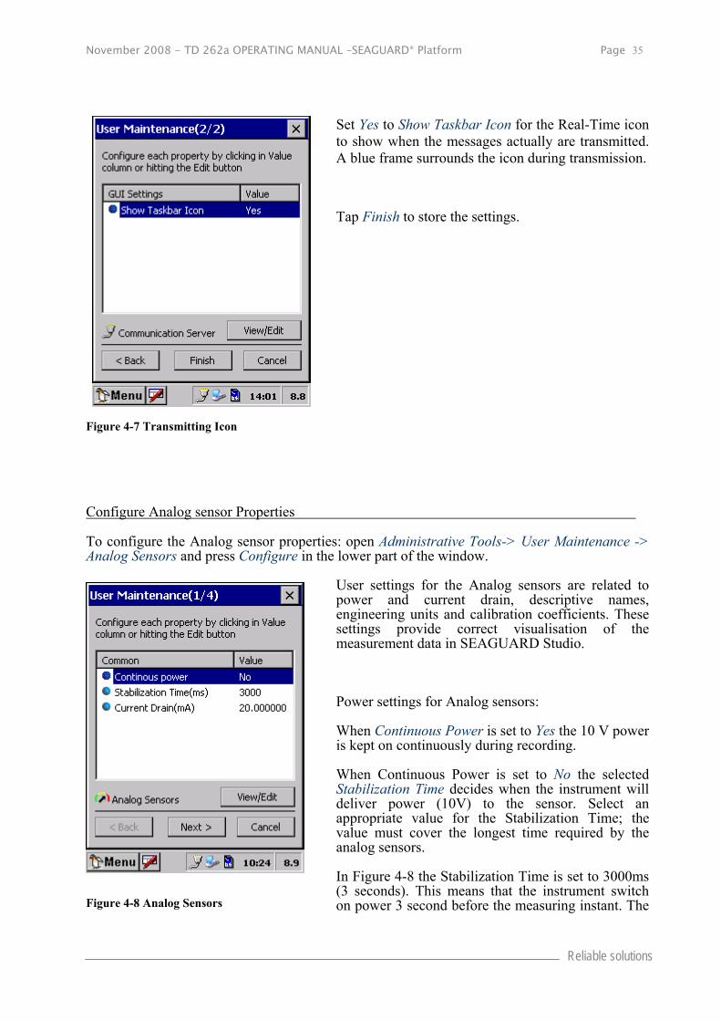
Set Yes to Show Taskbar Icon for the Real-Time icon to show when the messages actually are transmitted. A blue frame surrounds the icon during transmission.
Tap Finish to store the settings.
Configure Analog sensor Properties
To configure the Analog sensor properties: open Administrative Tools-> User Maintenance -> Analog Sensors and press Configure in the lower part of the window.
User settings for the Analog sensors are related to power and current drain, descriptive names, engineering units and calibration coefficients. These settings provide correct visualisation of the measurement data in SEAGUARD Studio.
Power settings for Analog sensors:
When Continuous Power is set to Yes the 10 V power is kept on continuously during recording.
When Continuous Power is set to No the selected Stabilization Time decides when the instrument will deliver power (10V) to the sensor. Select an appropriate value for the Stabilization Time; the value must cover the longest time required by the analog sensors.
In Figure 4-8 the Stabilization Time is set to 3000ms (3 seconds). This means that the instrument switch on power 3 second before the measuring instant. The
Figure 4-7 Transmitting Icon
Figure 4-8 Analog Sensors

Page 36 November 2008 - TD 262a OPERATING MANUAL –SEAGUARD® Platform
AANDERAA DATA INSTRUMENTS
power is switched off immediately after the measurement is taken.
Set the total Current drain as the sum of the current drain from each analog sensor; the instrument can calculate the current drain for the deployment.
Note! The total current drain is an input to the calculator.
Tap Next to continue the configuration.
Rename the Analog sensor’s Channel names for easy recognition later. The default names are Channel 1, Channel 2, Channel 3, and Channel 4, respectively.
Select the Channel, press View/Edit and type the name as the Value setting.
Tap Next to type the engineering unit for the sensor measurements; the engineering unit will appear in SEAGUARD Studio. In the example given in Figure 4-10, the channel unit has been set to V (Voltage).
Tap Next to enter calibration coefficients.
Figure 4-9 Analog Sensors
Figure 4-10 Set Engineering Units

November 2008 - TD 262a OPERATING MANUAL –SEAGUARD® Platform Page 37
Reliable solutions
To set the sensor calibration coefficients:
1. Select the sensor channel, refer Figure 4-11, press View/Edit in the lower part of the window; a window similar to Figure 4-12 appears.
2. Select and Edit each Index; Index 0 and Index 1 are values in an equation forming a linear relationship between the raw data readings and the measurements in engineering units:
Index 0 + Index 1 x N
Where N is the raw data readings.
Tap OK to return to the window shown in Figure 4-22.
Tap Finish to store the configuration. The configured name will appear e.g. in the SEAGUARD Studio.
Figure 4-11 Configure each analog sensors Calibration Coefficients.
Figure 4-12 Set Calibration Coefficients.

Page 38 November 2008 - TD 262a OPERATING MANUAL –SEAGUARD® Platform
AANDERAA DATA INSTRUMENTS
Sensor Monitor Open Administrative Tools-> Sensor Monitor.
Sensor Monitor can be used as a direct reading of the sensor; the function is mainly used for test purposes.
Select a sensor from the list, and press Start, refer Figure 4-13.
The next window shows sensor information like the Node Description, Product name and number and Serial number, refer Figure 4-14.
The number of sensor parameters and the processing time is also viewed in the window.
Select an Update Interval for the sensor monitoring, and press Start to start monitoring the sensor readings.
Figure 4-13 Sensor Monitor
Figure 4-14 Start Monitoring

November 2008 - TD 262a OPERATING MANUAL –SEAGUARD® Platform Page 39
Reliable solutions
The parameter reading in engineering units is shown as illustrated in Figure 4-15. The reading updates according to the update interval. Press Freeze to temporarily stop the update, Press Start to restart the monitoring (Start is the same button as Freeze).
Press Cancel to stop the monitoring.
Calculations of Power and Storage Capacity In Calculator you can find the Instruments estimated Battery and Storage capacity based on the current configuration. Refer Figure 4-16 Summary page.
You can also see more details regarding the power drain and storage, refer Figure 4-17 and Figure 4-18.
Select the applied battery from the list in the Summary page. The calculations are shown in the lower part of the window, refer Figure 4-16 Summary page.
Press Add to define a new battery in the list. Refer page 41 for a description. Pres Delete to remove a battery from the list.
Note! Power calculations are not available when Real-Time Output is enabled.
Figure 4-15 Sensor Reading
Figure 4-16 Summary page

Page 40 November 2008 - TD 262a OPERATING MANUAL –SEAGUARD® Platform
AANDERAA DATA INSTRUMENTS
In the Power page, you can see the average current drain for the deployment, and the number of records the battery can supply (based on the capacity of the battery that you selected in the summary page).
You can also see the individual power drain of each sensor in the system, refer Figure 4-17.
In the Storage page, you can see the size of the installed SD card, the available storage, the total record size and the number of records that can be stored based on the available storage capacity, refer Figure 4-18.
You can also see the storage requirements of each sensor in the system per recording.
Note! Sensors that provide several measurement parameters also take up more storage.
Figure 4-17 Power Calculations.
Figure 4-18 Storage Calculations.

November 2008 - TD 262a OPERATING MANUAL –SEAGUARD® Platform Page 41
Reliable solutions
Define/Add new Battery details
You can specify your own battery; refer the Summary page shown in Figure 4-16.
Press Add and type a Battery Description, Normal Voltage, Empty Voltage and the Battery Capacity; refer Figure 4-19.
Press OK to store the changes. The defined battery will show in the battery list; refer Figure 4-20.
Figure 4-19 Define a new Battery.
Figure 4-20 The new Battery in shown in the list.

Page 42 November 2008 - TD 262a OPERATING MANUAL –SEAGUARD® Platform
AANDERAA DATA INSTRUMENTS
Import/Export Configuration The Import/Export Configuration offers import and export of configuration settings from the Deployment Settings and System Configuration categories.
Applications for Import/Export:
Backup (export) current configuration to the SD card.
Restore (import) a previously saved configuration.
Restore (import) a configuration used in a previous recording (the configuration is automatically stored to the data session folder when a recording is started, refer CHAPTER 3, page 30).
Copy (import) a configuration from another instrument.
Import a configuration that was modified or created with the Seaguard Offline Configuration PC software.
Press Export to save the current configuration to the SD card.
Press Import to get a configuration file from the SD card and start the Import Wizard.
Figure 4-21 Import/Export Configuration.

November 2008 - TD 262a OPERATING MANUAL –SEAGUARD® Platform Page 43
Reliable solutions
Export: Type a file name to store current configuration to the SD card. A message box appears with the message Export OK if the export succeeded.
.
Import: Select the correct configuration file from the SD card. If the file contains a valid configuration, the import wizard will start.
If the configuration file is not valid, you will get a warning.
Figure 4-22 Export Configuration file to SD card.
Figure 4-23 Import Configuration file to SD card.

Page 44 November 2008 - TD 262a OPERATING MANUAL –SEAGUARD® Platform
AANDERAA DATA INSTRUMENTS
The product number and configuration version are used as criteria to match a node configuration in the file against a node on the instrument. Import is available if both the product number and configuration version are equal.
All nodes that are available for import are checked by default. Uncheck a node’s checkbox to de-select the import.
A Node Mismatch means that the configuration file does not contain any matching
configuration. Import is therefore not available for this node.
A Node Warning indicates an ambiguity between the source and target nodes due to
serial number mismatch or multiple source selection. If the configuration of a node with a warning symbol is selected for import, the wizard will guide you through these warnings to enable import, refer Figure 4-25 and Figure 4-26.
The Accept Serial Number 0 checkbox is displayed if one of the node serial numbers in the file is 0, and the corresponding node on the instrument is different from 0. If checked, serial number 0 will be accepted without any warnings displayed (refer TD275 Seaguard Offline Configuration, for the usage of serial number 0).
Press Next to continue or Cancel to abort the import wizard.
Note: Some sensors with an early software version do not support configuration version handling and will be given configuration version 0. If the configuration structure in the file differs from the one on the instrument, there is a possibility that import is unavailable for sensors with configuration version 0.
Figure 4-24 Import Wizard.

November 2008 - TD 262a OPERATING MANUAL –SEAGUARD® Platform Page 45
Reliable solutions
The Serial Number Mismatch warning appears when the matching node in the configuration file has a different serial number than the node on the instrument. The import must be confirmed by checking Please confirm import.
Note! If the serial number is 0, this warning can be avoided by checking the Accept Serial Number 0 on the Import Wizard Start Page, refer Figure 4-24.
Press Next to continue, Back to go to the previous page or Cancel to abort the Import Wizard.
The Multiple source selection warning appears when there is more than one available configuration for a target node in the configuration file. The preferred source for import can be selected in the Import Source drop-down box. If one of the source nodes has a matching serial number, the node will be selected by default.
Press Next to continue, Back to go to the previous page or Cancel to abort the import wizard.
Example: Figure 4-26 shows that the sensor named Pressure # 18 on the instrument can choose to import the settings from either Pressure #18 or Pressure #19 in the configuration file.
Figure 4-25 Warning message; Serial Number Mismatch.
Figure 4-26 Warning message; Multiple Source Selection.
Page 46 November 2008 - TD 262a OPERATING MANUAL –SEAGUARD® Platform
AANDERAA DATA INSTRUMENTS
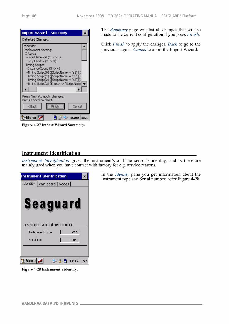
The Summary page will list all changes that will be made to the current configuration if you press Finish.
Click Finish to apply the changes, Back to go to the previous page or Cancel to abort the Import Wizard.
Instrument Identification Instrument Identification gives the instrument’s and the sensor’s identity, and is therefore mainly used when you have contact with factory for e.g. service reasons.
In the Identity pane you get information about the Instrument type and Serial number, refer Figure 4-28.
Figure 4-27 Import Wizard Summary.
Figure 4-28 Instrument’s identity.
November 2008 - TD 262a OPERATING MANUAL –SEAGUARD® Platform Page 47
Reliable solutions
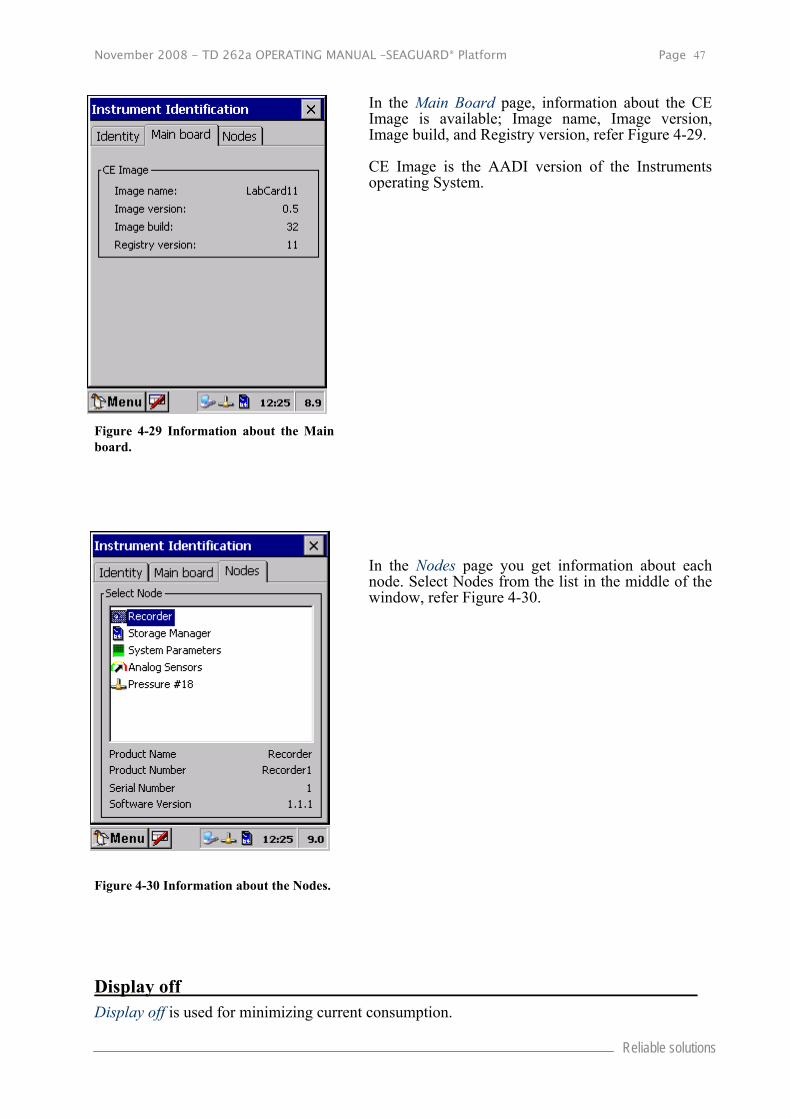
In the Main Board page, information about the CE Image is available; Image name, Image version, Image build, and Registry version, refer Figure 4-29.
CE Image is the AADI version of the Instruments operating System.
In the Nodes page you get information about each node. Select Nodes from the list in the middle of the window, refer Figure 4-30.
Display off Display off is used for minimizing current consumption.
Figure 4-29 Information about the Main board.
Figure 4-30 Information about the Nodes.

Page 48 November 2008 - TD 262a OPERATING MANUAL –SEAGUARD® Platform
AANDERAA DATA INSTRUMENTS
Command prompt
Command Prompt is used for running DOS programs. It is mainly used when manually updates from SD card should be driven.
Licensed Features –Option Modules
A licensed feature is enabled by installing a license key. The license key can be installed from a license file on the SD card or entered directly as a 16 digits number code. The license key is Instrument unique (based on the product- and serial number) and can not be installed in multiple instruments.
Note! Make sure that the SEAGUARD® Image version supports the new option. An Image upgrade can be necessary.
Open Administrative Tools-> Option Modules.
The license key or the license file can be received by e-mail. Download the license file to the SEAGUARD® SD card and install the SD card in the instrument.
The installation procedure is independent of which module to enable; we will illustrate the installation with the AADI Real-Time Module.
Figure 4-31 Information about the Nodes.

November 2008 - TD 262a OPERATING MANUAL –SEAGUARD® Platform Page 49
Reliable solutions
Start installing the license by either:
Press Install from SD card to install the license key as part of the license file. All license files on the SD card are automatically detected and installed. When installed from the license file, the key is entered automatically.
Or select the correct module and press Enter Key to enter the license key directly, refer Figure 4-33.
The license key number format is:
XXXX-XXXX-XXXX-XXXX.
If the license file/key is valid for the instrument/module you are asked Do you wish to install the Module? Press Yes to install or press No to abort the installation.
You are told to restart the instrument. Refer CHAPTER 1, page 11 and 13 for deployment configuration and setup issues.
Figure 4-32 Install license key.
Figure 4-33 Enter License key
Figure 4-34 Information about the Nodes.

Page 50 November 2008 - TD 262a OPERATING MANUAL –SEAGUARD® Platform
AANDERAA DATA INSTRUMENTS
When the license file has been installed from the SD card, you are notified with some installation requirements and setup issues. You are also notified if the SEAGUARD® Image version does not support the option module.
Read the instructions on screen. Press OK to finish the installation.
Figure 4-35 Installation from SD card provides the user with some Installation Information.
November 2008 - TD 262a OPERATING MANUAL –SEAGUARD® Platform Page 51
Reliable solutions
CHAPTER 5 Control Panel
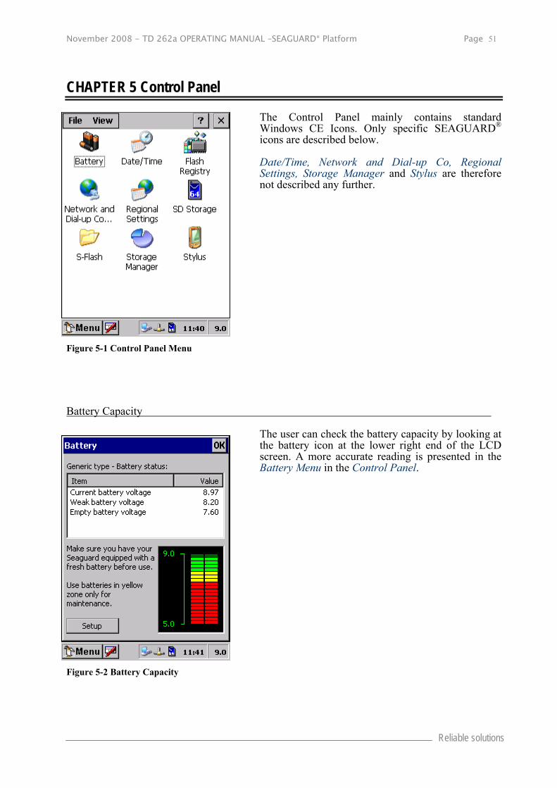
The Control Panel mainly contains standard Windows CE Icons. Only specific SEAGUARD® icons are described below.
Date/Time, Network and Dial-up Co, Regional Settings, Storage Manager and Stylus are therefore not described any further.
Battery Capacity
The user can check the battery capacity by looking at the battery icon at the lower right end of the LCD screen. A more accurate reading is presented in the Battery Menu in the Control Panel.
Figure 5-1 Control Panel Menu
Figure 5-2 Battery Capacity

Page 52 November 2008 - TD 262a OPERATING MANUAL –SEAGUARD® Platform
AANDERAA DATA INSTRUMENTS
Flash Registry
With Flash Registry you can store current registry content in persistent flash memory.
For more information of Flash Registry and updating of Flash Registry refer subchapter Software update of Main Board in CHAPTER 8.
SD Storage
In the SD Storage menu you find status about Storage Memory and you are able to Erase Storage on SD Card or Check Storage.
Figure 5-3 Flash Registry
Figure 5-4 SD Card

November 2008 - TD 262a OPERATING MANUAL –SEAGUARD® Platform Page 53
Reliable solutions
S-Flash
In the S-Flash menu you find status about the Serial Flash memory status.
You are also able to Erase or Check out the Serial Flash in the lower part of the window.
Important! Do not delete the S-Flash without consulting AADI personnel. The Recorder, storage manager, analog configuration are stored in the S-Flash and will be lost if deleted.
Figure 5-5 S-Flash Status

Page 54 November 2008 - TD 262a OPERATING MANUAL –SEAGUARD® Platform
AANDERAA DATA INSTRUMENTS
CHAPTER 6 SEAGUARD Studio
SEAGUARD® creates a data session folder containing several files. The complete folder must be imported into SEAGUARD Studio. The folder name is automatically created based on the deployment date and time: Instrument_Serialno_yyyymmdd_hhmm, refer Figure 6-1.
This chapter guides you in SEAGUARD Studio: how to import your measurement data folder, how to open and customise graphs for best visualisation of your data, and how to export graphs or data set.
Note! Install the SEAGUARD Studio from the installation CD.
Important! Always use the latest version of the SEAGUARD Studio Software. Download the latest version from our customer web site that you find at www.aadi.no , or contact your local representative or e-mail [email protected]
Import Data Note! We recommend that you copy all of the data session folders from the storage device (SD card) to a directory with names that links to the deployments.
A new measurement set must be imported into SEAGUARD Studio:
1. Connect your SEAGUARD® Instrument to the PC, refer the section Connection between the SEAGUARD® Instrument and a local PC, page 14. Copy your data session folder from the SD card to a folder on your PC. Refer Retrieval of the Instrument, page 65 for more information about importing data from SD card to PC.
2. Start SEAGUARD Studio.
3. Click the import button or select Import in the file menu..
4. Browse for the data session folder in which you copied your data, and click OK, refer Figure 6-1.
A progress bar informs you the download status.
Figure 6-1 Browse for Folder

November 2008 - TD 262a OPERATING MANUAL –SEAGUARD® Platform Page 55
Reliable solutions
Figure 6-2 SEAGUARD Studio Main window to the right, and the Control panel to the left.
When the data session folder has been imported, the data list is seen in the main window, and a control panel is found to the left, refer Figure 6-2.
Each node has its separate sheet in the Data list; each Record is numbered and has a Time tag in GMT.
The Control panel consists of a Setup view, a Graph view and a Tasks view. Setup holds information about the deployment configuration and settings, Graphs View visualises your measurements, and you can import/export data set from the Tasks view. Refer the next pages for guides.
Note! Several data sets can be imported into SEAGUARD Studio at the same time for comparisons between measured parameters from different deployments.
Customising Graphs
To display a graph: click the Graphs tag at the bottom of the control panel, select Sensor Values versus Time under General Line Graphs, and start configuring, refer Figure 6-3.
Expand the data set to view nodes and the measured parameters. Select one or more parameter from the listed nodes.
By default, none of the parameters are selected. When selected, the icon in front of the parameter name turns red, and a small mark will show next to the icon.

Page 56 November 2008 - TD 262a OPERATING MANUAL –SEAGUARD® Platform
AANDERAA DATA INSTRUMENTS
Note! When you expand a second node, the first nodes parameters are not longer listed; all selected parameters will show on the graph.
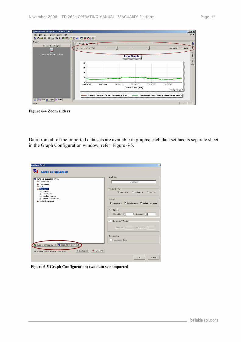
When the parameters have been selected, type Graph Title, add Legend, Time zooming sliders etc from the right part of the graph configuration window. Include time zooming sliders to confine the time interval without deleting records, refer Figure 6-4.
Right click the icons on the toolbar above the main window/control panel to reconfigure the graph setup, add cursor, reset graph, store graphs, etc. Hold down CTRL + left mouse button allows you to select a graph area to zoom in.
Figure 6-3 Graph Configuration; single data set
November 2008 - TD 262a OPERATING MANUAL –SEAGUARD® Platform Page 57
Reliable solutions
Figure 6-4 Zoom sliders
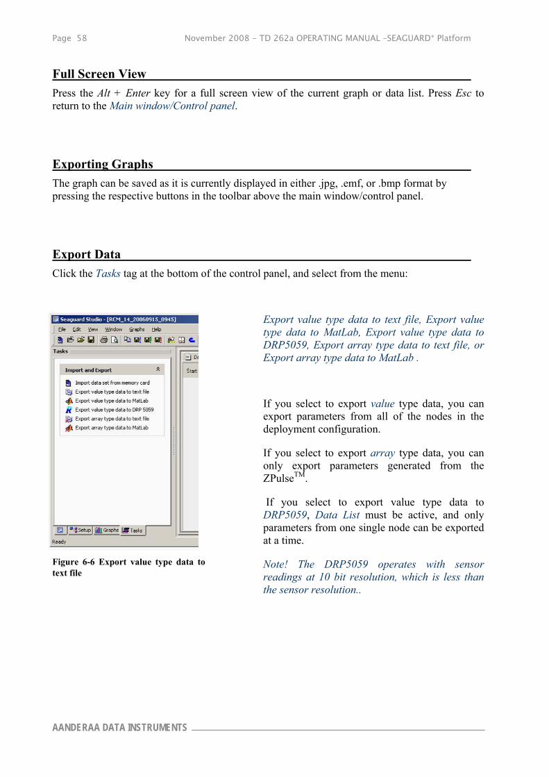
Data from all of the imported data sets are available in graphs; each data set has its separate sheet in the Graph Configuration window, refer Figure 6-5.
Figure 6-5 Graph Configuration; two data sets imported
Page 58 November 2008 - TD 262a OPERATING MANUAL –SEAGUARD® Platform
AANDERAA DATA INSTRUMENTS
Full Screen View
Press the Alt + Enter key for a full screen view of the current graph or data list. Press Esc to return to the Main window/Control panel.
Exporting Graphs
The graph can be saved as it is currently displayed in either .jpg, .emf, or .bmp format by pressing the respective buttons in the toolbar above the main window/control panel.
Export Data
Click the Tasks tag at the bottom of the control panel, and select from the menu:
Export value type data to text file, Export value type data to MatLab, Export value type data to DRP5059, Export array type data to text file, or Export array type data to MatLab .
If you select to export value type data, you can export parameters from all of the nodes in the deployment configuration.
If you select to export array type data, you can only export parameters generated from the ZPulseTM.
If you select to export value type data to DRP5059, Data List must be active, and only parameters from one single node can be exported at a time.
Note! The DRP5059 operates with sensor readings at 10 bit resolution, which is less than the sensor resolution..
Figure 6-6 Export value type data to text file

November 2008 - TD 262a OPERATING MANUAL –SEAGUARD® Platform Page 59
Reliable solutions
Expand the data set to view nodes and the parameters from each node. Select the parameters to be exported from the list. The bullet in front of the parameter name turns red when checked. The Record number and Time Tag in GMT will also be exported. The exported files include headers.
Select Date format if export to Text file (not optional if export to MatLab has been selected).
Select start and end record; the default setting is to export all records. Press the Export button to start the export function.
Browse for the correct folder to save the file.
If exporting to text file, enter a file name; the file format will be .txt. One single file is generated; the parameters from the first node are listed at the top of the file, while parameters from the second node follows after the last record, etc. The .txt file can be viewed in e.g. MS Excel.
If exporting to MatLab, the file name will be the node name; the file format is .cvs. The Export to
MatLab function generates one file for each node you choose to export parameters from. The .cvs file can be viewed in e.g. MS Excel. Import the .cvs file in Matlab using the Import File function.
If exporting to DRP5059, enter a file name. Two files will be generated: one .asc file with the measured parameters (in the raw data format used in DRP5059), and one .sti file with the calibration coefficients and other information required for import into DRP5059. Refer the operating Manual for DRP 5059, TD 208, for import of data set.
Edit listed data
When the data list is open, you can remove selected records, or remove all but selected records, refer Figure 6-8 top two options. Mark the desired records, right-click the mouse and select either to remove the selected records, or to remove all but selected records.
Figure 6-7 Export value type data to text file

Page 60 November 2008 - TD 262a OPERATING MANUAL –SEAGUARD® Platform
AANDERAA DATA INSTRUMENTS
Graphs that are open during the editing session will be deleted.
Note! To select more than one record, press and hold the shift button on your keyboard while marking the records with the mouse or the arrow button (on the keyboard).
Important! When saving the modified data set, make sure you use the save as option to avoid overwriting and loosing the original data.
Splitting one data series into several shorter data series
Choosing one of these options remove selected records, or remove all but selected records, you can export a selection of your data set, either e.g. one week or one month, and save in separate folders for presentation or more analysis.
Setup
In the Setup page you can watch information about the instrument and sensors, as well as the Deployment Settings, refer Figure 6-9.
Figure 6-8 Edit the Data list

November 2008 - TD 262a OPERATING MANUAL –SEAGUARD® Platform Page 61
Reliable solutions
Figure 6-9 Setup

Page 62 November 2008 - TD 262a OPERATING MANUAL –SEAGUARD® Platform
AANDERAA DATA INSTRUMENTS
CHAPTER 7 Operating Instructions
Preparations for Use Perform deployment configurations and recording configurations (described in
CHAPTER 3):
1. Customise the Node Descriptions.
2. Open the System Configuration menu and enable/disable node parameters to be measured.
3. Open the Deployment Settings: set the recording interval and enable/disable nodes.
4. Configure Analog sensors settings if analog sensors are attached, refer CHAPTER 3 and CHAPTER 4.
5. Activate the Recorder menu. View the deployment settings and select to start the instrument instantly or at a postponed time.
6. After being armed, the instrument will automatically shut off the LCD display. The LCD may be reactivated by tapping the display. However, before putting the instrument into the pressure container, make sure the display is switched off to conserve power. If not done automatically, tap the Display Off menu item in the Administrative Tools menu, refer CHAPTER 4.
Important!
When disconnecting the instrument from external AC Power, remember always to screw the Cover Cap tightly onto the electrical terminal to avoid water infusing the instrument when deployed!
Make sure the O-ring inside the Cover Cap is clean and undamaged. Always grease the O-ring before deployment.
If your instrument is equipped with a pressure sensor, make sure you do not deploy the instrument at a greater depth than the maximum depth for the pressure sensor, unless a pressure stopper is installed on the pressure inlet.
Inspect O-ring grooves, and replace O-rings before deployment. Make sure that the O-ring on the Top-end plate is clean and greased.
Make sure that the protective cap is installed on the electrical terminal.
When the system is armed and ready for deployment, the main switch must stay switched on.
When placing the instrument into its pressure case we recommend that you insert the instrument 90 off orientation mark. When the instrument is resting on the O-ring, spin the instrument towards orientation.
Tighten the C-clamps until the Top-end plate rests against the top of the case. Avoid over tightening, as this will damage the clamp.

November 2008 - TD 262a OPERATING MANUAL –SEAGUARD® Platform Page 63
Reliable solutions
Illustrations of deployment preparations
Figure 7-1 Insert Instrument into Pressure Case.
Note! Lower the instrument carefully straight down into the pressure case, do not pinch or nick O-ring. With the instrument Top-end plate seated into pressure case, sin the Top-end plate assembly 180º on the O-ring in order to seat the O-ring and remove any possible contamination from between the O-ring and its sealing surfaces.
Figure 7-2 Tighten C-clamps until the pressure case rotates on the floor. Avoid over tightening as this will bend the C-clamps.

Page 64 November 2008 - TD 262a OPERATING MANUAL –SEAGUARD® Platform
AANDERAA DATA INSTRUMENTS
Important! When connecting one shackle to another, remember to use shackles of same type of metal to avoid corrosion.
Figure 7-4 Splice the rope and fasten it to the thimble attached to the shackle.
Figure 7-3 Fasten shackle in frame. Tighten thoroughly.
Figure 7-5 Lock the shackle with strips or locking wire. Locking wire is recommended for higher security in long deployments.

November 2008 - TD 262a OPERATING MANUAL –SEAGUARD® Platform Page 65
Reliable solutions
Retrieval of the Instrument
When the instrument is retrieved after deployment, remove marine growth and barnacles from the sensor(s) using a hand scrub. To remove seashells or corals use plastic handle or similar tools.
Note! Do not use any kind of steal brush or any sharp objects; this might damage the acoustic elements.
When inspecting, look for corrosion on connector’s cracks on the back potting of connectors and scratches on protecting cable(s) jacket.
Rinse the instrument in fresh water and dry it. The unit can then be opened and the instrument removed from its pressure container.
Figure 7-6 Mount the instrument into the frame.

Page 66 November 2008 - TD 262a OPERATING MANUAL –SEAGUARD® Platform
AANDERAA DATA INSTRUMENTS
Procedure for retrieving measurement data:
Stop the recorder if any battery capacity is left. Wait until the progress bar has completed.
Write down the time of the last recording.
Turn off the power switch in the front of the instrument.
Connect the standard cable 4299 between the instrument and your PC. Open the Windows Explorer and copy the measurement data from the SD card folder in the mobile device. OR via an SD card reader: Remove the data storage unit, the SD card, from the recording unit by releasing the screw cover below the display, and press the card in to have it released. Put the SD card into an SD reader connected to your PC and copy the measurement data.
Start up the SEAGUARD Studio and import your data as described in CHAPTER 4.
Connection and disconnection of sensors
Procedure for connecting a sensor
Important! Do not twist the sensor to connect it. Gently push down the sensor.
AiCaP sensors can be connected in sensor position 1-6 (refer Figure 5-8); Analog sensors (0-5V) must be connected in sensor position 2,3,4 and 5. AiCaP sensors in position 1,2,3,4,5 are connected directly onto the HUB, while AiCaP sensors in position 6 must be connected to the sensor board using a ribbon cable. Inspect and replace sensor O-rings if necessary. Align the orientation pin for correct orientation of the sensor.
For connections of the sensors, please follow the listed procedure (steps 1 to 8):
1. Remove the instrument from the pressure case by releasing the two C-clamps at the Top-end plate and lift the instrument.
2. Switch OFF the instrument.
3. Loosen the set screw that goes with the sensor position, refer Figure 7-11, rightmost illustration. Do not unscrew the set screw completely and remove it, as it might be lost.
4. Pull up the sealing plug. Clean the boreholes.
Figure 7-7 SD card

November 2008 - TD 262a OPERATING MANUAL –SEAGUARD® Platform Page 67
Reliable solutions
5. Inspect the O-rings of the new sensor. Follow option a - c depending on the type of sensor to connect/the sensor position on the Top-end plate:
a. AiCaP sensor in position 6: Disconnect the upper battery. Unscrew and remove the two screws that hold the top cover. Refer Figure 7-12. Remove the top cover. Thread the ribbon sensor cable through the borehole. Align the orientation pin for correct orientation of the sensor. Gently push down the sensor. Refer Figure 7-13. Connect the sensor cable to J6 on the HUB; refer Figure 7-14.
b. AiCaP sensor in position 1,2,3,4,5: Gently push down the sensor, refer Figure 7-11. Ensure that the red dip switch on the HUB is in off position, refer Figure 7-9.
c. Analog sensor in position 2,3,4,5: Gently push down the connecting end of the cable. Set the red dip switch on the HUB in on position, refer Figure 7-9. Attach the analog sensor to the adapter end of the cable.
6. Fasten the sensor position set screw.
7. Remount the top front cover, reinsert the upper battery, and tighten the battery lid.
8. Put the instrument back into the pressure case and tighten the C-clamps.
Important! Make sure that the sensors and the C-clamps are well tightened to prevent water to infuse the system. Do not over tight, as this will damage the sensors and the clamps.
Figure 7-8 Top view of Top-end plate; Sensor Positions.
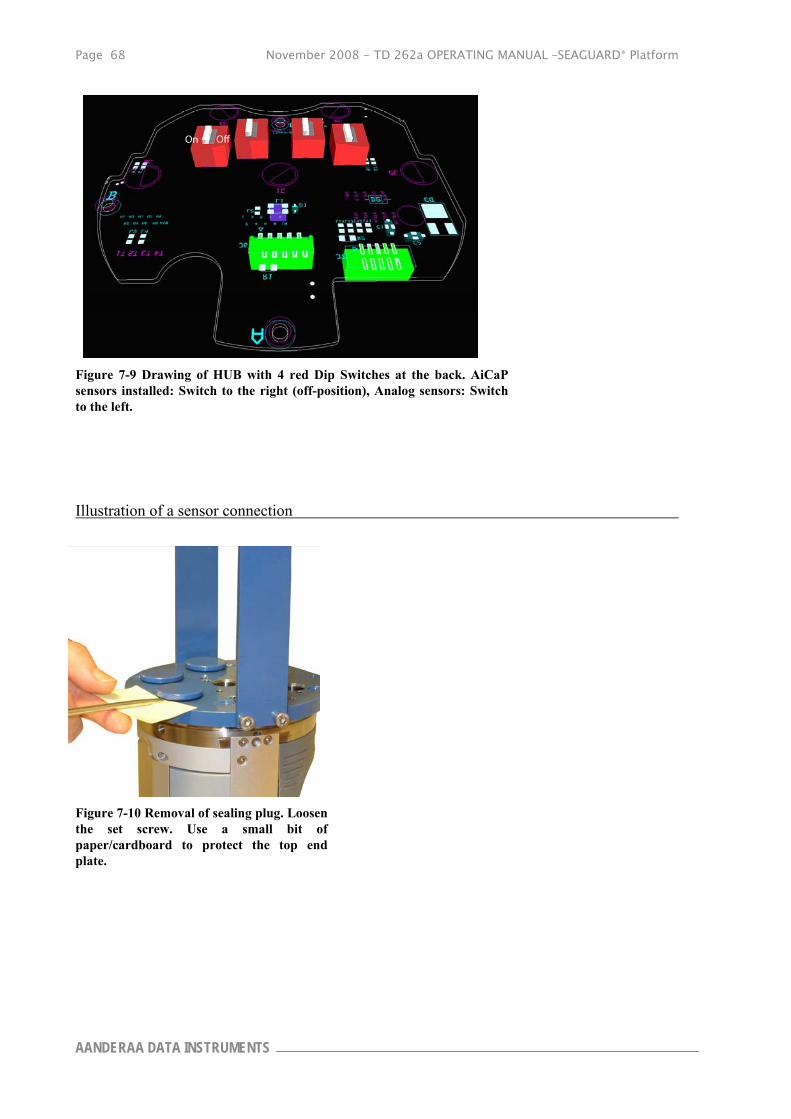
Page 68 November 2008 - TD 262a OPERATING MANUAL –SEAGUARD® Platform
AANDERAA DATA INSTRUMENTS
Figure 7-9 Drawing of HUB with 4 red Dip Switches at the back. AiCaP sensors installed: Switch to the right (off-position), Analog sensors: Switch to the left.
Illustration of a sensor connection
Figure 7-10 Removal of sealing plug. Loosen the set screw. Use a small bit of paper/cardboard to protect the top end plate.

November 2008 - TD 262a OPERATING MANUAL –SEAGUARD® Platform Page 69
Reliable solutions
AiCaP Sensor in position 1,2,3,4 and 5:
Figure 7-11 AiCaP sensors: Place the sensor according to the orientation pin. Push down the sensor and fasten the set screw.
AiCaP Sensor in position 6:
Figure 7-12 Open the battery lid, remove the upper battery, and unscrew the two top screws that holds the top front cover. Turn the instrument and pull off the top front cover.

Page 70 November 2008 - TD 262a OPERATING MANUAL –SEAGUARD® Platform
AANDERAA DATA INSTRUMENTS
Figure 7-13 Connect the sensor to the patch cable 3969492.
Figure 7-14 Connect the patch cable to HUB plug J6.
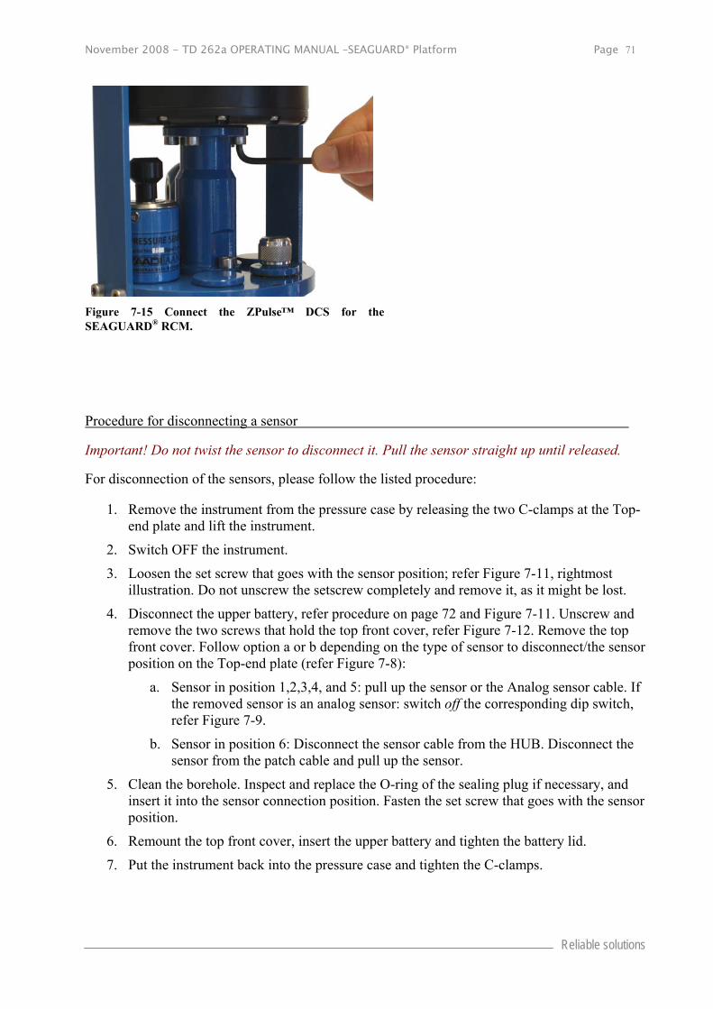
November 2008 - TD 262a OPERATING MANUAL –SEAGUARD® Platform Page 71
Reliable solutions
Figure 7-15 Connect the ZPulse™ DCS for the SEAGUARD® RCM.
Procedure for disconnecting a sensor
Important! Do not twist the sensor to disconnect it. Pull the sensor straight up until released.
For disconnection of the sensors, please follow the listed procedure:
1. Remove the instrument from the pressure case by releasing the two C-clamps at the Top-end plate and lift the instrument.
2. Switch OFF the instrument.
3. Loosen the set screw that goes with the sensor position; refer Figure 7-11, rightmost illustration. Do not unscrew the setscrew completely and remove it, as it might be lost.
4. Disconnect the upper battery, refer procedure on page 72 and Figure 7-11. Unscrew and remove the two screws that hold the top front cover, refer Figure 7-12. Remove the top front cover. Follow option a or b depending on the type of sensor to disconnect/the sensor position on the Top-end plate (refer Figure 7-8):
a. Sensor in position 1,2,3,4, and 5: pull up the sensor or the Analog sensor cable. If the removed sensor is an analog sensor: switch off the corresponding dip switch, refer Figure 7-9.
b. Sensor in position 6: Disconnect the sensor cable from the HUB. Disconnect the sensor from the patch cable and pull up the sensor.
5. Clean the borehole. Inspect and replace the O-ring of the sealing plug if necessary, and insert it into the sensor connection position. Fasten the set screw that goes with the sensor position.
6. Remount the top front cover, insert the upper battery and tighten the battery lid.
7. Put the instrument back into the pressure case and tighten the C-clamps.

Page 72 November 2008 - TD 262a OPERATING MANUAL –SEAGUARD® Platform
AANDERAA DATA INSTRUMENTS
Important! Make sure that the sealing plug and the C-clamps are tightened to ensure that no water will infuse the system. Do not over tighten as this will damage the sensors and the clamps.
Battery The battery compartment, at the rear of the SEAGUARD®, has room for two batteries, refer Figure 0-2.
Note! If the manufacture date of your lithium battery has expired one month, or you have not used the instrument the last month, you probably have to rejuvenate the battery to remove oxidizing. Start the instrument and wait for about 10 minutes while the battery is recharging or use a 100 Ω resistor up to 6.3 V for rejuvenating.
Removal and insertion of the Battery
To remove a battery from the SEAGUARD® instrument, follow the instructions below. The procedure is illustrated in Figure 7-12:
1. Place the instrument on the desk with the front facing down.
2. Loosen the centre screw at the rear of the instrument. NOTE! The screw can not be completely removed.
3. Flip up the battery cover.
4. Lift the battery straight out.
To insert the battery, follow these instructions:
1. Place the instrument on the desk with the front facing down.
2. Open the rear cover and remove the battery to be replaced, refer the procedure listed above.
3. Place the battery with the connection pins towards the centre, refer Figure 7-16.
4. Let down the battery cover.
5. Tighten the cover screw in the rear centre of the instrument.

November 2008 - TD 262a OPERATING MANUAL –SEAGUARD® Platform Page 73
Reliable solutions
Rejuvenating of Lithium batteries
If the manufacture date of your lithium battery has expired one month, or you have not used the instrument the last month, you probably have to rejuvenate the battery to remove oxidizing.
The rejuvenating can be done in two ways. Either start the instrument and wait for about 10 minutes while the battery is recharging or use a 100 Ω resistor up to 6.3 V, refer Figure 7-18.
Figure 7-16 The battery compartments are in the rear of the instrument.
Figure 7-17 Check the manufacture date

Page 74 November 2008 - TD 262a OPERATING MANUAL –SEAGUARD® Platform
AANDERAA DATA INSTRUMENTS
SD card Insert the SD card by first unscrewing the SD card-cover at the front of the instrument, refer Figure 7-7. Secondly insert the card with the terminals to the right.
Figure 7-18 Use a 100 Ω resistor up to 6.3 V to rejuvenate the battery.
November 2008 - TD 262a OPERATING MANUAL –SEAGUARD® Platform Page 75
Reliable solutions
CHAPTER 8 Maintenance
General Fouling of the SEAGUARD® Instrument will occur during deployment, especially at low latitudes. The use of anti-fouling paint must be considered based on your own experience.
The complete firmware in the SEAGUARD® may be upgraded by means of the SD card.
Yearly Maintenance
The procedure below indicates the minimum maintenance that must be carried out each year or every time the SEAGUARD® has been retrieved, two to four times a year for fixed installations depending on the environmental conditions, and every 3 years for factory service:
1. Remove marine growth and barnacles from the sensor(s) using a hand scrub. To remove sea
shells or corals use plastic handle or similar tools.
2. When inspecting, look for corrosion on connector’s cracks on the back potting of connectors
and scratches on protecting cable(s) jacket.
3. Rinse the exterior of the instrument in fresh water and let dry.
4. Clean the transducer head.
5. Open the instrument and check for leakage through the transducer head or in the pressure
case. If leakage, locate the source of the leakage and correct it.
6. Replace the zinc anodes and corroded parts if necessary.
7. Remove the O-rings.
8. Make sure that the O-ring seatings have a clean and smooth surface.
9. Lubricate the O-rings with grease (Klüber Lubrication Syntheso Glep 1 or similar synthetic
grease).
10. Replace the O-rings and pressure inlet.
11. If the transducer head has been disconnected, replace the silica gel bags.
12. Always install new O-rings on plugs that have been disconnected.
13. Check for deformation of the C-clamps. Replace if necessary.
14. Always apply TECTYL® on screws before installation to avoid crevice corrosion. Add also
TECTYL® around sensors and sealing plugs.
15. Check for scars on the EPOXY coating, the Top-end plate and the frame.
16. Clean the scars with Acetone.
17. Apply Repair Lacquer to repair the scars.
18. Control that the Electrical terminal is securely tightened.

Page 76 November 2008 - TD 262a OPERATING MANUAL –SEAGUARD® Platform
AANDERAA DATA INSTRUMENTS
Illustrations of Maintenance Procedures
Figure 8-2 Clean O-ring seating; instrument up-side-down.
Figure 8-1 Clean O-ring seating.
Figure 8-3 Fasten the set screws before putting on new O-ring.

November 2008 - TD 262a OPERATING MANUAL –SEAGUARD® Platform Page 77
Reliable solutions
Figure 8-4 Lubricate O-rings with grease. (Klüber Lubrication Syntheso Glep 1 or similar synthetic grease).
Factory Service Factory service is offered for maintenance, repair or calibration of instrument and parts. When returning instrument or parts for service, always include the Instrument Service Order, Form No. 135, see our web pages under ‘Support and Training’. Normal servicing time is four to six weeks, but in special cases the service time can be reduced. A main overhaul and service is recommended at the factory every three years.
Tools- and Maintenance Kit The manufacturer always keeps a stock of spare parts, accessories and consumable parts for quick delivery. Orders may be placed by fax, telephone or e-mail. See Table 8-1 for SEAGUARD® Tool Kit list, kit no. 3986A.
Figure 8-5 Add Tectyl® around sensors and sealing plugs.

Page 78 November 2008 - TD 262a OPERATING MANUAL –SEAGUARD® Platform
AANDERAA DATA INSTRUMENTS
Table 8-1 Tool Kit for SEAGUARD®, kit no. 3986A
Part. no Description Pieces
913013 Allen Key, NV 5 mm 1
913002A Allen Key, NV 4 mm 1
913022 Allen Key, NV 3 mm 1
913009 Allen Key, NV 2.5 mm 1
913035 T-10 Torx Screwdriver 1
913036 Flat Screwdriver (5 mm) 1
Maintenance Kit for SEAGUARD® This kit, part no. 3813, can be ordered from the manufacturer, refer to Table 8-2.
Table 8-2 Maintenance Kit 3813C/3813D for SEAGUARD®
Part. no Description Pieces
3813C (LW/IW)
Pieces
3813D (DW)
963352 Zinc Anode, Ø16 1 1
865001 O-Ring, SOR 71 (109.5 x3.0mm) 2
865000 O-Ring, SOR 72 (114.5x3.0mm) 2
863008 O-Ring, SOR 131 (18.1x1.6) 2 2
862011 O-Ring, SOR 125 (12.1x1.6) 2 2
963384 Pressure Inlet. 1 1
260087 Kluber, Syntheso GLEP l. 1 1
972579A Repair Lacquer, Jotun Blue. 1 1
972577 Tectyl 506. 10cl. 1 1
Software update of Main Board Instructions for uploading SEAGUARD® Image and descriptions around the procedures are given below.

November 2008 - TD 262a OPERATING MANUAL –SEAGUARD® Platform Page 79
Reliable solutions
Upload SEAGUARD® Image and Update New Registry
This section covers the task of upgrading a SEAGUARD® image (the main software of the unit) and the instrument database (the Registry).
The Registry is a vital part of the SEAGUARD® software. The registry holds information that the Instrument software applies to obtain information about different software components the system loads and unloads during an execution.
There are actually three copies of the Registry in the system. One is stored together with the image and is called the ROM version. Another is stored in Flash
and is called the Flash version. None of these are not lost when power is switched off.
When the instrument is switched ON, the operating system first looks for a copy of the Registry in the Flash; this version of the Registry is then copied into RAM and becomes the working Registry. If it does not find a valid Registry in the Flash, it copies the default ROM version (which is always present) into RAM and makes this one the working Registry.
When uploading an image from a SD card, this will erase the Flash version of Registry and force the instrument to use the ROM version that came with the new image.
Instructions for Uploading SEAGUARD® Image
If you already have a SD card with a SEAGUARD® Image ready, skip to step 5.
1. Use a SD card of at least 64 MB. Preferably use the SD card you received with the instrument.
2. Insert the SD Reader into the USB slot. Make sure a disk named Removable Disk appears in Explorer.
3. Erase all content of the SD card. Make sure that the file system is FAT in the properties command in Explorer. If you prefer to erase the card using the Format command, use FAT file format (not FAT32 or NTFS).
4. Copy the file named NK.nb0 to the SD card.
a) Select the file in the PC directory.
b) Right-click and select Copy.
c) Move to the Removable Disk folder, right-click and select Paste.
d) It takes some time to transfer the large file (32 MB). However, Explorer will report finish before the complete transfer has taken place. Thus, monitor the yellow light on the SD Reader for blinking. When the blinking stops, wait an additional minute.
e) Remove the SD card from the reader.
f) Click Refresh in Explorer (or go to another directory and back to Removable Disk) and confirm that there is no card in the reader.
g) Insert the SD card again and confirm that the file NK.nb0 actually exists on the card.
5. Install the SD card in the SEAGUARD® SD slot.

Page 80 November 2008 - TD 262a OPERATING MANUAL –SEAGUARD® Platform
AANDERAA DATA INSTRUMENTS
6. Open the SD card Housing in the SEAGUARD®.
7. Use the stylus to press and hold down the lower boot button in the SD card Housing; Switch ON the SEAGUARD® before releasing the boot button. Observe that the LCD screen turns on.
8. Release the boot button.
9. Tap the boot button once more; the LCD screen will now appear dark.
10. Release the boot button once more and wait until the LCD screen turns on again; the new image is about to be transferred. The image is large in size, and will take approximately 10 minutes to download.
11. When the download has finished, the ordinary start-up screen, with the Menu button appears.
12. Switch OFF the instrument using the power switch, and then switch it back ON to confirm that the new image has been installed.
Time settings Greenwich Mean Time (GMT) is set as default time zone. It is not possible to change the default setting.
You can adjust the time settings. Tap Control Panel in the main menu. Double click on the Date/Time icon, and you will get the Date/Time Properties, refer Figure 8-7.
Note! If possible we recommend to adjust the time every 3rd month.
Figure 8-6 The SD card Housing
Figure 8-7 Date/Time Properties
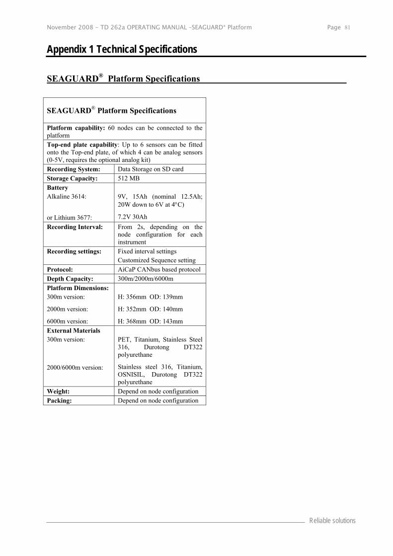
November 2008 - TD 262a OPERATING MANUAL –SEAGUARD® Platform Page 81
Reliable solutions
Appendix 1 Technical Specifications
SEAGUARD® Platform Specifications
SEAGUARD® Platform Specifications
Platform capability: 60 nodes can be connected to the platform
Top-end plate capability: Up to 6 sensors can be fitted onto the Top-end plate, of which 4 can be analog sensors (0-5V, requires the optional analog kit)
Recording System: Data Storage on SD card
Storage Capacity: 512 MB
Battery Alkaline 3614:
or Lithium 3677:
9V, 15Ah (nominal 12.5Ah; 20W down to 6V at 4C)
7.2V 30Ah
Recording Interval: From 2s, depending on the node configuration for each instrument
Recording settings: Fixed interval settings Customized Sequence setting
Protocol: AiCaP CANbus based protocol
Depth Capacity: 300m/2000m/6000m
Platform Dimensions: 300m version:
2000m version:
6000m version:
H: 356mm OD: 139mm
H: 352mm OD: 140mm
H: 368mm OD: 143mm
External Materials 300m version:
2000/6000m version:
PET, Titanium, Stainless Steel 316, Durotong DT322 polyurethane
Stainless steel 316, Titanium, OSNISIL, Durotong DT322 polyurethane
Weight: Depend on node configuration
Packing: Depend on node configuration