Page 0-Front Page - ActronAir
28
OPERATING INSTRUCTIONS FOR ACTRON AIR M SERIES CONTROL SYSTEM AM24 AM7 C COPY RIGHT SERIES M CONGRATULATIONS: on your purchase of an Actron Air air conditioning system.This unit has been maticulously designed to achieve maximum energy efficiency. It is manufactured from the highest quality materials has passed numerous "in house" and "external" inspection procedures, ensuring years of satisfactory operation. This "easy to read" Operating Instruction Manual is supplied to increase your understanding of the system. It will show "step by step" instructions. How to operate the system most effectively. How to save on energy costs. How to maintain your system. Please read this booklet carefully. ACTRON ENGINEERING PTY LTD
Transcript of Page 0-Front Page - ActronAir

OPERATING INSTRUCTIONSFOR ACTRON AIR M SERIES CONTROL SYSTEM
AM24
AM7
C COPY RIGHT
SERIESM
CONGRATULATIONS: on your purchase of an Actron Air air conditioning system.This unit has
been maticulously designed to achieve maximum energy efficiency. It is manufactured from the
highest quality materials has passed numerous "in house" and "external" inspection procedures,
ensuring years of satisfactory operation.
This "easy to read" Operating Instruction Manual is supplied to increase your understanding of
the system. It will show "step by step" instructions. How to operate the system most effectively. How to save on energy costs. How to maintain your system.
Please read this booklet carefully.
ACTRON ENGINEERING PTY LTD

1
All rights reserved. No part of the contents of this book may be reproduced or transmitted in
any form or by any means without the written permission of Actron Engineering Pty. Ltd.
Copyright 2002c
GENERAL INFORMATION
is when your system is operating on COOLING CYCLE,
the room air is circulated through the filter and indoor unit where heat, excess
moisture and dust are removed. The clean, cool air is then returned to your room.
Dust and other air borned particles are trapped in the filter, and condensed moisture
is drained away. The indoor heat is transferred by interconnecting refrigeration
pipes to the outdoor unit, which then exhaust this heat to the outdoor atmosphere.
SUMMER OPERATION
is just the reverse use of the system to obtain heat into our
rooms. During the HEATING CYCLE, the outdoor unit extracts heat from the
outside air and then transferred by the same interconnecting pipes to the indoor
unit where the circulated air is heated and returned to your rooms. Again, the room
air is filtered reducing dust and other particles.
WINTER OPERATION
with its
Microprocessor Control it automatically filters, circulates and conditions by cooling
or heating the indoor air to give you complete year-round climate control.
YOUR ACTRON AIR SYSTEM IS A STATE OF THE ART PRODUCT
You will find instructions for two types of wall controllers,
the standard model (AM24) and the 7-Day Programmable model (AM7). The AM7
control has all the features the AM24 has but with the addition of a fully
programmable 7-Day timeclock.
NOTE: Most of the basic functions are shown using the AM24 control, the AM7
buttons are the same for basic functions.
INSIDE THIS MANUAL
SAFETY AND OPERATION PRECAUTIONS
NEVER remove any access panels or
guards as this could cause injury from electric shock and burns from extremely
hot components. Never allow any bodily parts such as fingers or objectsto protrude through the fan guards or any other opening as they could cause
personal injury and damage the air conditioner.
ACCESS PANELS AND GUARDS:
The air conditioner must never be operated without a
Return air Filter as this will allow a build up of dust etc on the Indoor Coil.
This is very difficult to clean and causes the system to operate inefficiently or
even fail.
RETURN AIR FILTER:
The main power ( Outside switch
board ) to the system must be kept ON at all times to prevent damage to the
outdoor compressor unit. Should the main power be disconnected or interrupted
for 6 hours or longer, then no attempt should be made to start the systemfor 2 hours after the power has been restored to outdoor unit. This allows the
compressor to warm up, and remove any liquid refrigerant that may cause damage.
CRANKCASE HEATER PRECAUTION:

2
Contents
General information.........................Safety and operation precautions...System information.............................Advanced features.........................
Page 1Page 1Page 2Page 3
Programming the events..................Cancelling an individual event.........Repeating a days events andtimes...............................................
Page 15Page 16
Page 17
Wall controller functions (AM24).......Cooling operation..............................Heating operation..............................Auto operation..................................Circulation operation.........................Countdown timer (off)......................Countdown timer (on).......................
Page 4Page 5Page 6Page 7Page 8Page 9Page 10
Wall controller functions..................7-Day timeclock operation...............Setting the time and day..................Activating and de-activatingthe 7-Day timeclock.........................
Page 11Page 12Page 13
Page 14
Zone controller functions.................Room temperature display...............Dual wall control operation..............Setting the upper and lowertemperature limits.............................
Page 18Page 18Page 19
Page 20
Operating tips for extreme weather(Summer).........................................Operating tips for extreme weather(Winter)...........................................Energy conservation tips.................Maintenance...................................Trouble shooting.............................Resetting the wall control................
Page 21
Page 22Page 23Page 24Page 25Page 26
Basic Operation
7-Day Programmable Model
(Model AM7-- only)
Additional Features
Additional Information
System Information
Air Conditioner
The air conditioner model and serial number is situated on the access panel of the
outdoor unit bottom left corner.
Model No.
Serial No.
Wall Controller
The wall controller model number is situated inside the wall controller flip lid.
Model No.
Installer
Company Name
Phone No.
Technicians Name
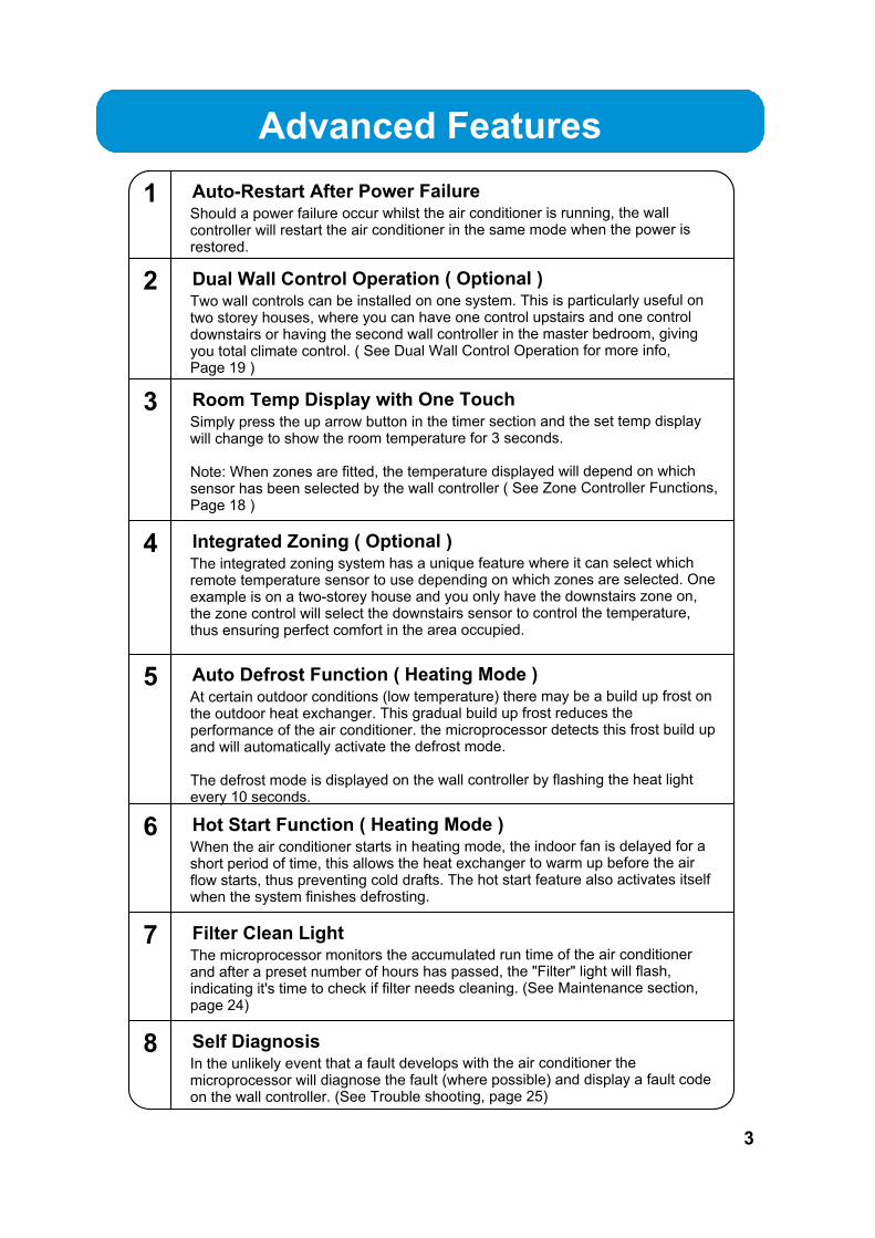
Advanced Features
1 Auto-Restart After Power FailureShould a power failure occur whilst the air conditioner is running, the wall
controller will restart the air conditioner in the same mode when the power is
restored.
3 Room Temp Display with One TouchSimply press the up arrow button in the timer section and the set temp display
will change to show the room temperature for 3 seconds.
Note: When zones are fitted, the temperature displayed will depend on which
sensor has been selected by the wall controller ( See Zone Controller Functions,
Page 18 )
4The integrated zoning system has a unique feature where it can select which
remote temperature sensor to use depending on which zones are selected. One
example is on a two-storey house and you only have the downstairs zone on,
the zone control will select the downstairs sensor to control the temperature,
thus ensuring perfect comfort in the area occupied.
Integrated Zoning ( Optional )
5At certain outdoor conditions (low temperature) there may be a build up frost on
the outdoor heat exchanger. This gradual build up frost reduces the
performance of the air conditioner. the microprocessor detects this frost build up
and will automatically activate the defrost mode.
The defrost mode is displayed on the wall controller by flashing the heat light
every 10 seconds.
Auto Defrost Function ( Heating Mode )
6When the air conditioner starts in heating mode, the indoor fan is delayed for a
short period of time, this allows the heat exchanger to warm up before the air
flow starts, thus preventing cold drafts. The hot start feature also activates itself
when the system finishes defrosting.
Hot Start Function ( Heating Mode )
7The microprocessor monitors the accumulated run time of the air conditioner
and after a preset number of hours has passed, the "Filter" light will flash,
indicating it's time to check if filter needs cleaning. (See Maintenance section,
page 24)
Filter Clean Light
8In the unlikely event that a fault develops with the air conditioner the
microprocessor will diagnose the fault (where possible) and display a fault code
on the wall controller. (See Trouble shooting, page 25)
Self Diagnosis
3
2 Dual Wall Control Operation ( Optional )Two wall controls can be installed on one system. This is particularly useful on
two storey houses, where you can have one control upstairs and one control
downstairs or having the second wall controller in the master bedroom, giving
you total climate control. ( See Dual Wall Control Operation for more info,Page 19 )

1
2
3
46
7
8
23 24
25 26
RUMPUS
FAMILY
BEDROOMS
LIVING
FANCONTROL
SET
AUTOHEAT COOL
TEMP
TIMER
ON
OFF
CONT HIGH MID LOW COOL AUTO HEAT RUN TIMER FILTER
ON OFF ROOM
1
3
2
4
5
9
10
11
12
13 14 15 16 17 18 19
22
21
20
WALL CONTROLLER FUNCTIONS
Cool indicator
Auto indicator
Heat indicator
On indicator (Not used on AM24)
Off indicator (Not used on AM24)
Room temperature indicator
Run indicator
Timer indicator
Filter indicator light
14
15
16
17
18
19
20
21
22
This light indicates the systemwill automatically select heatingor cooling operation.
Flashes when digital display is showingroom temperature.
The run light is illuminated when theoutdoor machine is running.
( See maintenance section, page 24 )
Zone one button23
Zone two button24
Zone three button25
Zone four button26
On/Off button
Operation mode button
1
2Selects cooling, heating & automodes.
Timer/clock setting buttonand room temp. display.
Timer operation button
Temperature setting button
Temperature setting button
Fan control button
Timer setting button androom temp. display.
Continuous indicator
High fan speed indicator.
Medium speed fan indicator.
3
4
5
6
7
8
Activates timer.
Lowers room temperature.
Raises room temperature.
Changes fan speed and selectscontinuous or non-continuous fanoperation.
9
10
11
Is illuminated when fan is set tocontinuous mode.
Low speed fan indicator.12
Digital display13Displays setpoint, room temp, timer hours.
4
Model AM24
These Functionsare the Same forModel AM7

Cooling Operation
3
OFF
The system will retain your last setting until next operation.
Press the ON/OFF button again.
1
2
3
4
AUTOHEAT COOL
Press the ON/OFF button
Press the button until COOL is illuminated
Set the desired temperature by pressingeither the UP or DOWN arrow key.
Maximum temperature setting 30. Minimum temperature setting 16. For a WARMER room temperature, press the UP arrow key. For a COOLER room temperature, press the DOWN arrow key.
Adjust the desired fan speed by pressingthe FAN CONTROL button.When your air conditioner is turned ON the indoor fan can run continuously
and is indicated by the CONT. light. This is generally preferred during the
cooling mode to ensure maximum air circulation. However, during the
heating mode this can create the effect of cool drafts. It then would be
preferable to have the indoor fan, cycle On and Off automatically with theOutdoor Unit. This is selected by pressing the FAN button untilthe CONT. light is Off.
RUMPUS
FAMILY
BEDROOMS
LIVING
FANCONTROL
SET
AUTOHEAT COOL
TEMP
TIMER
ON
OFF
CONT HIGH MID LOW COOL AUTO HEAT RUN TIMER FILTER
ON OFF ROOM
1
2
3
4
1
3
2
4
3
5
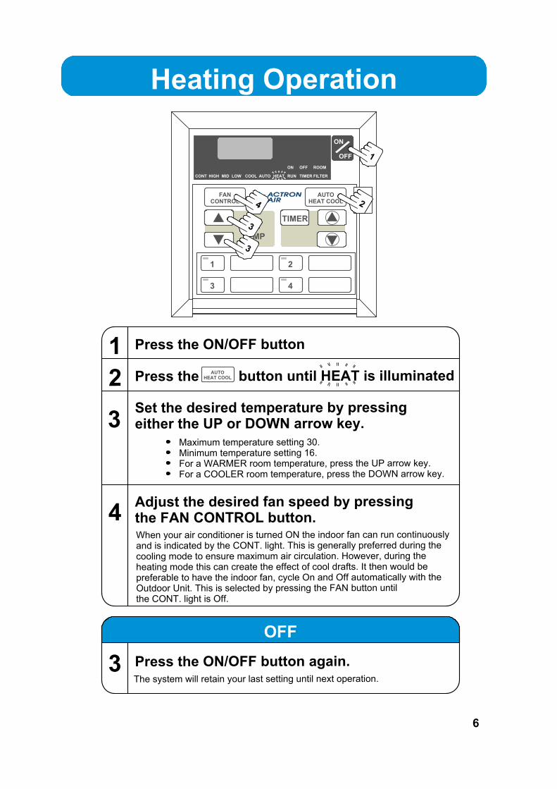
Heating Operation
3
OFF
The system will retain your last setting until next operation.
Press the ON/OFF button again.
When your air conditioner is turned ON the indoor fan can run continuously
and is indicated by the CONT. light. This is generally preferred during the
cooling mode to ensure maximum air circulation. However, during the
heating mode this can create the effect of cool drafts. It then would be
preferable to have the indoor fan, cycle On and Off automatically with theOutdoor Unit. This is selected by pressing the FAN button untilthe CONT. light is Off.
RUMPUS
FAMILY
BEDROOMS
LIVING
FANCONTROL
SET
AUTOHEAT COOL
TEMP
TIMER
ON
OFF
CONT HIGH MID LOW COOL AUTO HEAT RUN TIMER FILTER
ON OFF ROOM
1
2
3
4
1
3
2
4
3
AUTOHEAT COOL
1
2
3
Press the ON/OFF button
Press the button until HEAT is illuminated
Set the desired temperature by pressingeither the UP or DOWN arrow key.
Maximum temperature setting 30. Minimum temperature setting 16. For a WARMER room temperature, press the UP arrow key. For a COOLER room temperature, press the DOWN arrow key.
4Adjust the desired fan speed by pressingthe FAN CONTROL button.
6

Auto OperationAutomatically Changes between Heating to Cooling
RUMPUS
FAMILY
BEDROOMS
LIVING
FANCONTROL
SET
AUTOHEAT COOL
TEMP
TIMER
ON
OFF
CONT HIGH MID LOW COOL AUTO HEAT RUN TIMER FILTER
ON OFF ROOM
1
2
3
4
1
3
2
4
3
When your air conditioner is turned ON the indoor fan can run continuously
and is indicated by the CONT. light. This is generally preferred during the
cooling mode to ensure maximum air circulation. However, during the
heating mode this can create the effect of cool drafts. It then would bepreferable to have the indoor fan, cycle On and Off automatically with the
Outdoor Unit. This is selected by pressing the FAN button untilthe CONT. light is Off.
AUTOHEAT COOL
1
2
3
Press the ON/OFF button
Press the button until AUTO is illuminated
Set the desired temperature by pressingeither the UP or DOWN arrow key.
Maximum temperature setting 30. Minimum temperature setting 16. For a WARMER room temperature, press the UP arrow key. For a COOLER room temperature, press the DOWN arrow key.
4Adjust the desired fan speed by pressingthe FAN CONTROL button.
3The system will retain your last setting until next operation.
Press the ON/OFF button again.
OFF
7

Circulation Operation
RUMPUS
FAMILY
BEDROOMS
LIVING
FANCONTROL
SET
AUTOHEAT COOL
TEMP
TIMER
ON
OFF
CONT HIGH MID LOW COOL AUTO HEAT RUN TIMER FILTER
ON OFF ROOM
1
2
1
3
2
4
3
1
2
3
4
OFF
The system will retain your last setting until next operation.
Make sure the system is off.
Adjust the FAN SPEED by pressing theFAN CONTROL button.
Press the ON/OFF button.
Press the FAN CONTROL button
8

Timer Operation
RUMPUS
FAMILY
BEDROOMS
LIVING
FANCONTROL
SET
AUTOHEAT COOL
TEMP
TIMER
ON
OFF
CONT HIGH MID LOW COOL AUTO HEAT RUN TIMER FILTER
ON OFF ROOM
1
2 3
4
1
3
2
4
3
3
1
2
3
4
Timer Cancellation
5
Changing the Hours Set
Press the ON/OFF button
Press the TIMER button
Set the desired hours for the system toturn OFF by pressing either the UP orDOWN arrow keys.
Press the ON/OFF button again
Follow the steps 2 and 3
Make sure the system is running andthe operating conditions are those desired.
The up/down arrow keys must be pressed whilst Timer is flashing.The timer can be set from 0.5 hours to 24 hours.
9
OFF TimerFunction

Timer Operation
RUMPUS
FAMILY
BEDROOMS
LIVING
FANCONTROL
SET
AUTOHEAT COOL
TEMP
TIMER
ON
OFF
CONT HIGH MID LOW COOL AUTO HEAT RUN TIMER FILTER
ON OFF ROOM
1
2 3
4
1
3
2
4
3
3
1
2
3
Press the TIMER button
Set the desired hours for the system toturn ON by pressing either the UP orDOWN arrow keys.
Make sure the system is OFF
The up/down arrow keys must be pressed whilst Timer is flashing.The timer can be set from 0.5 hours to 24 hours.
4
Timer Cancellation
5
Changing the Hours Set
Press the ON/OFF button again
Follow the steps 2 and 3
When the air conditioner is started by the timer function, it will onlystart in Auto mode.Circulation mode can not be turned on by the Timer.
Notice
10
ON TimerFunction

11
ON
OFF
CONT HIGH MID LOW COOL AUTO HEAT RUN TIMER FILTER
ON OFF ROOM
1
3
2
4
MON TUE WED THU FRI SAT SUN
PM
AM
FANCONTROL
SET
TEMP
AUTOHEAT / COOL
SET 1 2
TIME
EVENT
CLOCK
EXIT REPEAT
TIMECLOCKPROGRAM
COUNTDOWNTIMER
29
27
28
30
31 32 33
34
Time clock Program buttonFor setting the clockFor entering the 7-day time clock menu.
Exit buttonFor quick exit from any program menu.
Repeat buttonFor repeating the previous day settings to the current day.
Day indicatorDisplay the day of the week when the time is shown and which day is selected for programming.
AM / PM indicators
Digital displayDisplays the set temp, room temp, current time, count down timer times and event times.
Program and event menu
On / Off indicatorsIndicates whether you are setting the "ON" time or "OFF" time in the 7-day time clock.
7-Day Programmable Model
27
28
29
30
31
32
33
34
See model AM24for other buttonfuctions on page 4
Wall ControllerFunctions forModel AM7

12
7-Day Programmable Model (cont....)
The 7 Day timeclock feature on the AM7 controller allowsyou to set the air conditioner to turn ON and OFF at differenttimes for each day of the week.
MON TUE WED THU FRI SAT SUN
EVENT1
ONTIME
OFFTIME
EVENT2
ONTIME
OFFTIME
6:00am
10:00am
4:00pm
10:00pm
6:00am
10:00am
4:00pm
10:00pm
6:00am
10:00am
4:00pm
10:00pm
6:00am
10:00am
4:00pm
10:00pm
6:00am
10:00am
1:00pm
11:00pm
7:00am
9:00am
------
------
8:00am
12:00am
------
------
Example of a typical timeclock set-up
Each day can have two programmed events.
Each event has an ON and OFF time.
Cancelling an individual event
Go to the ON time for the event you wish to cancel and pressthe ON/OFF button.------ will be displayed indicating the event is cancelled.
ON
OFF
CONT HIGH MID LOW COOL AUTO HEAT RUN TIMER FILTER
ON OFF ROOM
1
3
2
4
MON TUE WED THU FRI SAT SUN
PM
AM
FANCONTROL
SET
TEMP
AUTOHEAT / COOL
SET 1 2
TIME
EVENT
CLOCK
EXIT REPEAT
TIMECLOCKPROGRAM
COUNTDOWNTIMER
TimeclockOperation

13
7-Day Programmable Model (cont....)
ON
OFF
CONT HIGH MID LOW COOL AUTO HEAT RUN TIMER FILTER
ON OFF ROOM
1
3
2
4
MON TUE WED THU FRI SAT SUN
PM
AM
FANCONTROL
SET
TEMP
AUTOHEAT / COOL
SET 1 2
TIME
EVENT
CLOCK
EXIT REPEAT
TIMECLOCKPROGRAM
COUNTDOWNTIMER
3
1
2
4
6
5
Setting the Timeand Day
Press the "TIMECLOCK PROGRAM" button.
Press the "TIMECLOCK PROGRAM" button.3
5
6
2 Adjust the "hours" by using the buttons.
Set the "Day" by using the buttons.
Press the TIMECLOCK PROGRAM button3 times and "SET" will be illuminatedwith "TIME" flashing.
1
4 Adjust the "minute" by using the buttons.
Battery Backup
During a power failure, the clock retains the time and dayvia the backup battery inside the wall control.1

14
7-Day Programmable Model (cont....)
ON
OFF
CONT HIGH MID LOW COOL AUTO HEAT RUN TIMER FILTER
ON OFF ROOM
1
3
2
4
MON TUE WED THU FRI SAT SUN
PM
AM
FANCONTROL
SET
TEMP
AUTOHEAT / COOL
SET 1 2
TIME
EVENT
CLOCK
EXIT REPEAT
TIMECLOCKPROGRAM
COUNTDOWNTIMER
3
1
2
4
Activating andDe-activating the7-Day Timeclock
1
2
3
4
1
2
3
4
Press the TIMECLOCK PROGRAM button twice
Press the ON/OFF until "ON" is flashing
Press the EXIT button
TIMECLOCK should now be illuminated
Press the TIMECLOCK PROGRAM button twice
Press the ON/OFF until "OFF" is flashing
Press the EXIT button
TIMECLOCK should not be illuminated
Activating
De-Activating

15
ON
OFF
CONT HIGH MID LOW COOL AUTO HEAT RUN TIMER FILTER
ON OFF ROOM
1
3
2
4
MON TUE WED THU FRI SAT SUN
PM
AM
FANCONTROL
SET
TEMP
AUTOHEAT / COOL
SET 1 2
TIME
EVENT
CLOCK
EXIT REPEAT
TIMECLOCKPROGRAM
COUNTDOWNTIMER3
1
2
2
7-Day Programmable Model (cont....)
Programmingthe Events
1Press the TIMECLOCK PROGRAM buttonrepeatedly until event "1" and "MON" is illuminated.
You are now setting MONDAY, event 1, ON time.
Use the buttons to adjust the time.2
3Press the TIMECLOCK PROGRAM buttonto move to event 1 off time and follow step 2.
4Press the TIMECLOCK PROGRAM buttonto move to the next event.
The event time is entered once you press theTIMECLOCK PROGRAM button.If you press the EXIT button before moving to the next event,the time you have programmed will not be entered.
5Repeat the above steps until you haveprogrammed all the events you require.
Programming Past Midnight
1 Event On times can be set to 11:45 PM of the current day.
2Event Off times can be set to 9:00 AM the followingmornings.
If you program event 1 past midnight, event 2 will be automatically cancelled.
Notice

16
7-Day Programmable Model (cont....)
ON
OFF
CONT HIGH MID LOW COOL AUTO HEAT RUN TIMER FILTER
ON OFF ROOM
1
3
2
4
MON TUE WED THU FRI SAT SUN
PM
AM
FANCONTROL
SET
TEMP
AUTOHEAT / COOL
SET 1 2
TIME
EVENT
CLOCK
EXIT REPEAT
TIMECLOCKPROGRAM
COUNTDOWNTIMER
23
1
Cancelling anIndividual Event
Press the ON/OFF button
Press the TIMECLOCK PROGRAM buttonrepeatedly until the "ON" time for the eventyou wish to cancel is displayed.
- - - will be displayed indicating the eventis cancelled.
See 7-Day timeclock operation for programmingsequence. Page 12
Repeat the above steps until you havecancelled all the desired events.
1
2
3
5
4
Repeat steps 1 & 2 as above
Press the ON/OFF button until thetime re-appears.
Re-Activate an Event
1
2

17
7-Day Programmable Model (cont....)
ON
OFF
CONT HIGH MID LOW COOL AUTO HEAT RUN TIMER FILTER
ON OFF ROOM
1
3
2
4
MON TUE WED THU FRI SAT SUN
PM
AM
FANCONTROL
SET
TEMP
AUTOHEAT / COOL
SET 1 2
TIME
EVENT
CLOCK
EXIT REPEAT
TIMECLOCKPROGRAM
COUNTDOWNTIMER
3
2
2
Repeating a Days Events & Times
This feature allows you to automatically repeatthe previous days events and times, thus eliminatingthe need to re-enter the events and times.
1Go to the day you wish to copy and programyour events and times.
Press the TIMECLOCK PROGRAM button untilthe following days, event 1, ON time is displayed.
See "Programming the Events" page 15.
2Display shows "SET", "EVENT", "1", "TIMECLOCK" and "ON"
3Press the REPEAT button
You have now copied the previous days events into the current day displayed.
4 Repeat steps 2 and 3 for the remaining days.

RUMPUS
FAMILY
BEDROOMS
LIVING
FANCONTROL
SET
AUTOHEAT COOL
TEMP
TIMER
ON
OFF
CONT HIGH MID LOW COOL AUTO HEAT RUN TIMER FILTER
ON OFF ROOM
3
1
3
2
4
1
1
1
1
ZONE CONTROLLER FUNCTIONS
Turning Zones ON & OFF
Lights are illuminated when zone is turned on.2
The minimum of one zone is to be left on, this is controlled automatically
by the wall control and will not allow you to turn off the last zone operating.
Notice
1 Press the zone button to turn zones on & off.
Room Temperature Display
3 Press the "Up Arrow" button in the timer section and theroom temperature will be displayed for 3 seconds
The room temperature displayed can be the temperature at thewall controls or remote wall sensors or a combination of both.
Notice
18

Dual Wall Control Operation
The air conditioner can be operated from either wall control.
Information displayed on the two wall controls is identical.
Last wall control used has priority.
Eg. 1
Using wall control one, the cooling operation is started, both wall controls
will now show the system is in cooling mode. If another person uses wall
control two to select heating operation, the system will now change to the
heating operation and both wall controls will display the system is in heating
operation.
Eg. 2
Using wall control two, the circulation operation is selected, both wall controls
will now show the system in circulation mode. If another person uses wall
control two to select cooling operation, the system will now change to the
cooling operation and both wall controls will display the system is in cooling
operation.
WALLCONTROL ONE
WALLCONTROL TWO
MIMICCONTROL
19

20
Setting the Upper and Lower Temperature Limits
This feature allows you to set theupper and lower temperature limitson your wall control.
This can be used in a variety of ways.
1. You may want the maximum set-temp limited to 25C and the minimum set- temp to 20C, thus stopping anyone from setting the temperature to high or low.2. You may want to lock the set-temp to 22C to stop anyone else adjusting the set-temp up and down. To do this, simply adjust the upper and lower limit until they are the same.
ON
OFF
CONT HIGH MID LOW COOL AUTO HEAT RUN TIMER FILTER
ON OFF ROOM
1
3
2
4
MON TUE WED THU FRI SAT SUN
PM
AM
FANCONTROL
SET
TEMP
AUTOHEAT / COOL
SET 1 2
TIME
EVENT
CLOCK
EXIT REPEAT
TIMECLOCKPROGRAM
COUNTDOWNTIMER
1A1C
3
1B
1Press the timer (1A) button, followed by the set-temp (1B) button.
You must press the two buttons in quick succession.
SETTING THE LOWER LIMIT
The display will now show the "Lower" limit for 3 seconds andthis is indicated by "LOW" also being illuminated.2
Whilst the "Lower limit" is displayed, use the set-temp arrowbuttons to adjust up or down.3
After 5 seconds the Lower limit will be automatically excepted.4
1Press the timer (1A) button, followed by the set-temp (1C) button.
You must press the two buttons in quick succession.
SETTING THE UPPER LIMIT
The display will now show the "Upper" limit for 3 seconds andthis is indicated by "HIGH" also being illuminated.2
Whilst the "Upper limit" is displayed, use the set-temp arrowbuttons to adjust up or down.3
After 5 seconds the Upper limit will be automatically excepted.4
You cannot adjust the upper limit below your current set-temp.You cannot adjust the lower limit above your current set-temp.
Notice
Default Upper and Lower Limits = Upper (30C) Lower (16C)
It is recommended not to adjust the upper and lower limits outside the defaults above,
before talking with your installer. Doing so, may cause damage to your system and void
warranty
Adjustable limitsUpper = 10C to 32CLower = 10C to 32C

Operating Tips for Extreme Weather
1 Always test run your air conditioner a few weeksbefore the start of summer and make sure it's coolingsufficiently.
Summer
2
If the air conditioner needs servicing, it's advised you have thisdone before the summer season arrives.
A HOT day is forecast for tomorrow, what should youdo?
Always start the air conditioner early in the morning and keep thehouse/office cool. If you try and start the air conditioner in the afternoon
when the house/office is already very hot, if may take a while to cool down.
Keep all curtains and windows closed. Also stop drafts coming in from your
front & back doors.
If you have zones, turn off any you are not using and close doors to these
areas, this will give you more cooling capacity in the areas you need.
Ask your installer on the minimum zones you should use on your system.
21
Always allow the necessary amount of fresh air into rooms.
Notice

Operating Tips for Extreme Weather
1 Always test run your air conditioner a few weeksbefore the start of winter and make sure it's heatingsufficiently.
Winter
2
If the air conditioner needs servicing, it's advised you have thisdone before the winter season arrives.
A COLD day is forecast for tomorrow, what should youdo?
You can leave air conditioner running overnight, but lower the set point
2-4 degrees from your normal setting to help save electricity. This will
prevent the house/office from becoming to cold overnight and thusenabling the air conditioner to warm the house/office quicker whenyou raise the temperature set point back to your usual setting.ORStart the air conditioner a couple of hours earlier than younormally would in the morning.
If outside conditions are very cold (approx. 7 C or lower)supplementary heating may be used such as electric orgas heaters to complement & speed the heating up.
Keep all curtains and windows closed. Also stop drafts coming in from your
front & back doors.
If you have zones, turn off any you are not using and close doors to these
areas, as this will give you more heating capacity in the areas you need.
Ask your installer on the minimum zones you should use on your system.
Always allow the necessary amount of fresh air into rooms.
Notice
22

Energy Conservation Tips
1 For the most efficient operation, keep the windows and doors closed
including unused areas where possible. They not only help to insulate
against heat and cold, they also reduce dust, pollen and noise.
Occasionally allow fresh air into rooms and offices that are closed off.
Should you wish to leave your air conditioner on over night during thewinter. Set your thermostat down by 2 to 4 degrees Celsius when going
to bed and reset to your normal setting upon arising, as there is no reason
to pay for extra electricity when you are under the blankets. This can also
apply during the summer nights and therefore raise the temperature by 2
to 4 degrees Celsius.
On days when extreme conditions of High or Low temperatures prevail
and the home is unoccupied, it can be practical to leave the airconditioner ON. However to reduce energy costs, set the temperature up
2 to 4 degrees Celsius (Cool Mode) for summer and down 2 to 4 degreesCelsius (Heat Mode) for winter and reset to your normal setting upon
returning. This will provide a more comfortable situation and reduce the
high heat load as the Air Conditioner not only has to cool or heat the air, it
also has to cool and heat the furniture, walls, floors and ceilings.
The normal setting recommended is 22 degrees Celsius for both summer
and winter.
By raising the set point by 1 C in summer or lowering the set point by1 C in winter can save approx. 10% on electricity costs.
2 If your air conditioner has zones fitted, always turn off the zones youaren't using as this will save energy by the air conditioner not having
to operate as long.
ZONING
23

Maintenance
Wall Controller Outlets and Return air
Wipe the controller with a dry cloth.Do not use water.
Dust off the outlets and return air, usea household duster. Do this regularlyto prevent any build up of dust or dirt.
Air Filter CleaningClean every 4 weeks or when the filter light is displayed on wall control.
2 Remove the filter by sliding it out from the grille.
1 Open the inlet grille.Caution, dust may fall from return air grille.
3 Clean the filterUsing a vacuum cleaner to remove the dust or wash the filter with water.
Be gentle when cleaning the filter to avoid tearing the filter material.
4 Replace filter.
Notice
INDOORUNIT
OUT LET RETURN AIR
24
Outdoor Unit
2 Keep grass or plants away from the unit. This will ensureyour air conditioner operates efficiently.
1 Do not obstruct airflow.
When the filter light is illuminated, check the air filter and cleanif necessary and press the ON/OFF button to extinguish filter light.Always check with your installer for the proper care andmaintenance of the filter system.
RUMPUS
FAMILY
BEDROOMS
LIVING
FANCONTROL
SET
AUTOHEAT COOL
TEMP TIM
ER
ON
OFF
CO
NTHIGH
MID
LOW
CO
OL
AUTO
HEATR
UNTIM
ERFILTER
ON
OFF
ROOM
1
3
2
4

Trouble Shooting
CONDITION CAUSES OR CHECK POINTS
Check that 5 minutes has passed from turn on time,as the system has inbuilt safety timers.Check thermostat settings are correct.Check the thermostat "set-point" is set low enoughfor cooling or high enough for heating.
The system does not start.
Check Zones are switched on (Where fitted)During heating operation, air does not flow out forapprox. 15 seconds after start up, this prevents colddrafts.During the defrost of the outdoor unit in heatingoperation, the indoor fan will not operate for severalminutes, this is to prevent cold air being blown intorooms.
Air does not flow.(Indoor Unit)
The cooling/heating function may not work effectivelywhen the "return air filter" is clogged with dust and dirt.Make sure the air inlet and air outlet on the outdoor unitare not blocked.The outside temperature is above or below the designconditions.
Cooling/Heating is notsufficient.
It is caused by the defrosting of the outdoor unit in heating operation in cold conditions.
Steam from outdoor unit.
This is normal during heating operation, it is due towater forming on the heat exchanger.
Water from outdoor unit.
When heating or cooling is started or stopped,a swishing or gurgling noise may be heard.This noise is generated by the refrigerantflowing between the outdoor and indoor units.A whooshing noise may be heard from theoutdoor unit during operation.This noise is generated when the refrigerantchanges direction in the defrost operation.On start up, the outdoor unit may be louderthan normal for a few seconds whilst thecompressor reaches the designated speedand operating pressure.During defrost operation the compressormay generate more noise than normal.
Occuring of noises
When EXX is displayed on the wall controller, take noteof the digits after E and contact your installer.
Fault Codes
Before contacting your installer, please have your air conditioners Model No. and
Serial No. with you. (See page 2)
25

Trouble Shooting (cont....)
CONDITION CAUSES OR CHECK POINTS
26
Set-temp can't be adjusted.
7-day timeclock is not turningthe air conditioner on and off.(7-day programmable model only)
Check the timeclock is activated (see page 14)
Check you don't have times overlaping fromanother day.Make sure your not trying to set the time past themaximum allowable (see programming past midnightpage 15)
7-day timeclock is notaccepting times you enter.
Check your wall control set-temp limits are not beingexceeded.Check the upper and lower temperarue are setcorrectly (see page 20).
Before contacting your installer, please have your air conditioners Model No. and
Serial No. with you. (See page 2)
Re-Setting The Wall Control
Note: This does not reset the 7-day timeclock features on the AM7 wall controller.
1 Make sure the air conditioner is in the OFF position.
2 Press and hold down FAN CONTROL + SET-TEMP DOWNARROW + ON/OFF.
All the display indicators will flash, with the ON/OFFindicators flashing for a further 20 seconds. The wall controlis now reset to the original factory settings.
Note: This will reset all the 7-Day timeclock programs.
1 Make sure the wall controller is in the OFF position.
2 Press TIMECLOCK PROGRAM button,followed by the ON/OFF button.You must press the two buttons in quick succession.
3 All the display indicators will light up for approximately 1 secondand then all timeclock programs have been re-set to theoriginal factory settings.
(7-day programmable model only)
Re-Setting All Functions For AM24 & AM7
Re-Setting The Timeclock (7-Day programmable model only)

Actron Engineering Pty LtdPrinted in Australia
Part No. 0500-005-02
HEAD OFFICE KINGS PARK SYDNEY AUSTRALIA
ABN 34002 767 240