Packers Downhole Equipments arial font -...
4
STORAGE FACILITIES TO L.P. SALES OR FLARE FROM ADDITIONAL SEPARATION FACILITIES REGULATOR VOLUME CHAMBER IF REQUIRED SCRUBBER LOW PRESSURE SUCTION SYSTEM COMPRESSOR HIGH PRESSURE GAS LINE ORIFICE FLANGE FOR GAS MEASUREMENT SUBSURFACE CHOKE OR ELECTRONIC CONTROLLER AS REQUIRED ORIFICE FLANGE FOR GAS MEASUREMENT REGULATOR SEPARATOR H. P. SALES VOLUME CHAMBER IF REQUIRED LIQUIDS PACKER HIGH PRESSURE GAS WELL IF AVAILABLE LIQUID DUMP TO ADDITIONAL WELLS GAS LIFT WELL INSTALLATION PACKER GAS LIFT VALVES FROM ADDITIONAL WELL OR WELLS SEPARATOR In order to boost production from wells, which do not flow at all or do not flow at optimum level, artificial systems using a variety of methods are used. These methods use Gas Lift, Plunger Lift, Chamber Lift, Rod Pumps, Submersible Pumps and so on. PARVEEN provides a complete line of Equipment and Services for such applications, e.g. Gaslift, Plunger Lift and Chamber Lift. Which artificial method will be most effective for a particular well can be determined by evaluating several factors such as well's production potential, Gas/Oil ratios, well bore deviation and size as well as corrosion / erosion potential of produced fluids. Other factors include availability of power source such as compressed gas, electricity, surface facility, service availability, space limitation and personnel capabilities. The diagram below provides the basic components of a Gas Lift System. In many fields, a high pressure well provides a readily available energy source. If sufficient gas pressure or volume is not available, a compressor can be utilized to operate a closed system. The Gas is recirculated through a compressor facility. Only minor amount of make up gas is needed to replenish gas lost in separation processing or as fuel for compressor facilities. COMPLETION SYSTEMS Basic Components for a Gas Lift System Gas Lift Equipment 115
Transcript of Packers Downhole Equipments arial font -...
STORAGE FACILITIES
TO L.P. SALESOR FLARE
FROM ADDITIONAL SEPARATION FACILITIES
REGULATOR
VOLUME CHAMBER IF REQUIRED
SCRUBBER
LOW PRESSURE SUCTION SYSTEM
COMPRESSOR
HIGH PRESSURE GAS LINE
ORIFICE FLANGE FOR GAS
MEASUREMENT
SUBSURFACE CHOKE OR ELECTRONIC CONTROLLER
AS REQUIRED
ORIFICE FLANGE FOR GAS MEASUREMENT
REGULATOR
SEPARATOR
H. P. SALES
VOLUME CHAMBER IF REQUIRED
LIQUIDS
PACKER
HIGH PRESSURE GAS WELL IF AVAILABLE
LIQUID DUMP
TO ADDITIONAL WELLS
GAS LIFT WELL INSTALLATION
PACKER
GAS LIFT VALVES
FROM ADDITIONALWELL OR WELLS
SEPARATOR
In order to boost production from wells, which do not flow at all or do not flow at optimum level, artificial systems using
a variety of methods are used. These methods use Gas Lift, Plunger Lift, Chamber Lift, Rod Pumps, Submersible
Pumps and so on. PARVEEN provides a complete line of Equipment and Services for such applications, e.g. Gaslift,
Plunger Lift and Chamber Lift.
Which artificial method will be most effective for a particular well can be determined by evaluating several factors
such as well's production potential, Gas/Oil ratios, well bore deviation and size as well as corrosion / erosion
potential of produced fluids. Other factors include availability of power source such as compressed gas, electricity,
surface facility, service availability, space limitation and personnel capabilities.
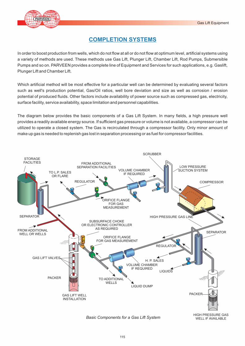
The diagram below provides the basic components of a Gas Lift System. In many fields, a high pressure well
provides a readily available energy source. If sufficient gas pressure or volume is not available, a compressor can be
utilized to operate a closed system. The Gas is recirculated through a compressor facility. Only minor amount of
make up gas is needed to replenish gas lost in separation processing or as fuel for compressor facilities.
COMPLETION SYSTEMS
Basic Components for a Gas Lift System
Gas Lift Equipment
115

FLOW CONTROL VALVE
INJECTION GAS
SIDE POCKETMANDRELS
SIDE POCKETMANDRELS
DUAL STRINGPACKER
PRODUCTION
SINGLE STRING PACKER
PRODUCTION
Schematic 1- The single string Gas Lift completion for intermittent lift applications utilizes a standing valve near the
bottom of the tubing to prevent Gas pressure surges against the reservoir during cyclic operations. A single zone
continuous lift installation would not require a standing valve but otherwise it will be identical. In either application
Conventional or Side Pocket Mandrel can be used. Side Pocket Mandrels are designed to provide the facility of
removing and replacing Gas Lift Valves without removing the tubing. These service operations are performed either by
using wireline, through - flow line (TFL) or coiled tubing methods depending on the completion configuration. Wire line
installations are more economical for servicing wells with vertical access, especially remote, offshore or other hard - to
- reach locations, since wireline units are light and portable. TFL and coil tubing service methods can provide
production maintenance for wells that require tubing loops, such as ocean floor completions, highly deviated wells,
extremely deep wells and any well where there is no straight or vertical access for wireline service.
Schematic 2 - This illustrates dual-string installations where Gas Lift Valves lift fluids from two zones using gas from a
common annulus. An installation can be designed, with proper well information, to produce and carry both zones to
depletion. The conditions affecting dual string design are casing size, distance between zones, well bore deviation,
continuous or intermittent lift and operator's preference. Gas lift valves should be of proportional response or
production pressure operated if the operation has to be trouble free.
Schematic 1 Single Zone Gas Lift
Installation
LIFT GAS
PACKER
STANDING VALVE (OPTIONAL)
FLOW CONTROL VALVE
Schematic 2 Dual String Gas Lift
Installation
COMPLETION SYSTEMS
116
Gas Lift Equipment

INJECTION GAS
SIDE POCKET MANDREL WITH GAS LIFT VALVE
INJECTION LINE (CONTROL LINE)
SIDE POCKET MANDREL WITH CHEMICAL INJECTION VALVE
LOCATED AND SEAL ASSEMBLY
PACKER
PRODUCTION FLUID
Schematic 3 - In the chamber lift system, one normally utilizes two packers, a standing valve, a perforated pup above
the bottom packer, and a differential vent valve just below the top packer, in addition to the Gas Lift Valve necessary to
unload and produce the well.
While the bottom injection pressure operated valve is closed, the standing valve is open. Fluid fills both the tubing and
annular space (chamber) between the two packers. The differential valve is open, and allows gas in the top of the
annular part of the chamber to bleed into the tubing as the chamber fills. When the chamber has filled to the point that
the liquid level is near the differential valve, the operating gas lift valve opens. A calculated gas volume enters the top of
the chamber, closing the bleed valve and standing valve, forcing accumulated liquids to U-tube from the chamber to
the tubing. Liquids are produced as a slug to the surface. As the tubing is cleared, the operating gas lift valve closes,
the standing valve and bleed valve open, and liquids again refill the chamber. The cycle then repeats.
If properly planned, a chamber lift system permits a larger volume of fluid to be produced by intermittent lifts from wells
with a high productivity index and low-to medium bottom hole pressure.
Schematic 4 - In certain cases, Chemical injection is desirable to be coupled with Gas Lift. Side Pocket Mandrels may
be run at pre-determined depths for Gas lift valves to be installed. An additional mandrel with a chemical injection valve
and injection line may also be run to desired depth on the same tubing string. Tubing / Casing annulus can be used for
gas injection and the injection line for chemical injection.
SIDE POCKET MANDRELSAND GAS LIFTVALVES
SIDE POCKETMANDREL FOR CHAMBER LIFT
DUAL OR BYPASSPACKER
SIDE POCKETMANDRELW/DIFFERENTIALVALVE
PERFORATED PUP JOINT
LOWER PACKER
STANDING VALVE
PRODUCTION
FLOW CONTROL VALVE
Schematic 3 Chamber LiftInstallation
Schematic 4 Chemical Injection/Gas
Lift Installation
COMPLETION SYSTEMS
117
Gas Lift Equipment

Schematic 5 - Macaroni tubing installation works well in either intermittent or continuous Gas Lift System. Essentially
the installation is the same as a single zone installation, except the size of the macaroni string is the limiting factor due
to ultra-slim hole conditions. It is an ideal method of artificial lift for slim hole completions.
Schematic 6 - This fig. shows a simple installation without packer application for unloading fluids in a gas well. Plunger
lift systems can effectively produce high GOR wells, water producing gas wells, or very low bottom hole pressure oil
wells (used with gas lift). Depending upon individual well requirements surface/subsurface equipment varies.
Installation may or may not require a packer and/or additional gas.
GAS LIFT VALVES
PACKER
PACKER
PACKER
FLOW CONTROL VALVE
ELECTRONIC CONTROLLER
MOTOR VALVE
ARRIVALSENSOR
SWITCH GAUGE
LUBRICATOR
FLOW TEE
CATCHER
MASTER VALVE
PLUNGER (EXPANDING PADWITH BYPASS)
BUMPER SPRING
TUBING OR COLLAR STOP
Schematic 5 Macaroni Installation
Schematic 6 Single Zone Plunger
Lift Installation
COMPLETION SYSTEMS
118
Gas Lift Equipment