Pacific Earthquake Engineering Research Center Repair ...
224
James C. Anderson Xiaojing Duan University of Southern California Repair/Upgrade Procedures for Welded Beam to Column Connections Pacific Earthquake Engineering Research Center PEER 1998/03 MAY 1998
Transcript of Pacific Earthquake Engineering Research Center Repair ...

James C. AndersonXiaojing Duan
University of Southern California
Repair/Upgrade Procedures for WeldedBeam to Column Connections
Pacific Earthquake EngineeringResearch Center
PEER 1998/03MAY 1998
i
Repair/Upgrade Procedures for WeldedBeam to Column Connections
James C. Anderson
University of Southern California
Xiaojing Duan
University of Southern California
A report to sponsors:National Science Foundation
American Institute of Steel ConstructionMatt Construction Company
Report No. PEER-98/03Pacific Earthquake Engineering Research center
College of EngineeringUniversity of California, Berkeley
May 1998

ii
ABSTRACT
Experimental and analytical studies are conducted on four repair/upgrade details for welded
moment connections. The first of these seeks to improve the weld material without doing anything
to the beam and column sections at the joint (weld enhancement). The simplest of these removes
the cracked weld material and replaces it with a more ductile, notch-tough weld material (weld
replacement). A more recently developed procedure places a layer of weld material having a
higher notch toughness on top of the existing welds (weld overlay).
The second weld repair/retrofit detail considers the addition of rectangular cover plates to the
top and bottom beam flanges. The plates which are the same width as the beam flange are beveled
to permit partial penetration welds along the sides. A variation of this detail adds a rectangular
miniplate which is half the length and width of a full sized plate to the top and bottom beam
flanges.
The third detail considers the addition of a vertical, triangular plate (fin) to the top and bottom
flanges of the beam in the plane of the web. A modification to the initial detail includes a hole in
the fin which moves the net section of the fin away from the column face and causes yielding to
occur at the hole rather than the column face. A fourth detail is a retrofit detail which considers a
reduced beam section formed by using drilled holes to approximate the geometry of a tapered cut
in the beam flanges.
These details are shown to provide varying degrees of improvement in connection behavior
with plastic rotation capacities between 1.5 percent and 4 percent being achieved. The best results
were obtained by the horizontal flange plates, both full sized and miniplate. The worst perfor-
mance occurred using a single flange plate. The two weld overlays tested attained plastic rotations
of 3 and 3.5 percent.
Detailed finite element analyses are conducted for all of these configurations. The analytical
model was used to give direction to the test program and to correlate with the test results. Calcu-
lated stresses in the analytical model are shown as colored stress contours. The analytical model
was loaded with an increasing, monotonic load at the beam tip. In this manner an estimate of the
skeleton curve of the hysteresis curve was obtained.
In order to repair connections in frames located on the perimeter of a building it is often nec-
essary to cut access windows in the web of the beam and in the panel zone of the column. One full
size specimen of this type was tested to failure to verify the performance of the connection after
the web windows were closed with welded plates. Results indicated that the windows create an
eccentricity which may cause premature buckling of the beam web.

iii
ACKNOWLEDGMENTS
The primary funding for this project was provided by the National Science Foundation and the
support of Dr. M.P. Singh and Dr. S.C. Liu is gratefully acknowledged. Material for the test spec-
imens was provided by Nucor-Yamoto Steel Company and material for an additional specimen
was provided by Brown-Strauss Steel. Fabrication was done by Lee & Daniel with funds provided
by the American Institute of Steel Construction (AISC), the Structural Steel Education Council
and the Structural Shape Producers Council. The efforts of Mr. Jack Lee in getting industry par-
ticipation in the fabrication of the test specimens was especially helpful. Fabrication drawings of
the connection details were provided by Baresel Corporation. Smith-Emery Company provided
ultrasonic testing services.
The authors would also like to thank Dr. Gregg Brandow and Mr. Peter Maranian of Brandow
and Johnston Associates for their interest in the project and helpful suggestions throughout the
course of the study. Thanks are also due Dr. Warner Simon for providing technical direction for
the design of the weld overlays. Interaction with many practicing structural engineers during the
course of the study was also extremely helpful. The advisory panel instituted at the beginning of
the study with ten members grew to more than twenty at the end. Participation of the senior author
on the City of Los Angeles Steel Committee under the direction of Mr. Richard Holguin was also
very beneficial. Finally, the senior author would like to thank his colleague, Professor Yan Xiao,
for his interest and suggestions throughout the course of the study.
Welding required for much of the repair/retrofit work was done by Mr. Phil Martinez (Bay
Area Welding). Mr. Jeff Nickler (Southwest Mobile Welding) and Mr. Jack Compton (College of
the Canyons) were instrumental in making the overlay welds. Graduate students Babak Mansouri,
Ali Rejae and Dan Dapudga helped with the instrumentation, setting up the test specimens and
other tasks as needed. These contributions are gratefully recognized.

iv
CONTENTS
ABSTRACT ............................................................................................................................ii
ACKNOWLEDGMENTS ........................................................................................................ iii
TABLE OF CONTENTS...........................................................................................................iv
LIST OF TABLES .....................................................................................................................vi
LIST OF FIGURES ..................................................................................................................vii
1.0 INTRODUCTION...............................................................................................................1
1.1 Overview and Problem Description .............................................................................1
1.2 Objective and Scope.....................................................................................................2
1.3 Approach ......................................................................................................................3
1.3.1 Weld Replacement ..............................................................................................3
1.3.2 Horizontal Flange Plates.....................................................................................3
1.3.3 Vertical Triangular Plates ....................................................................................4
1.3.4 Weld Overlay ......................................................................................................4
1.3.5 Other Procedures.................................................................................................4
2.0 FINITE ELEMENT ANALYSES .......................................................................................6
3.0 EXPERIMENTAL SYSTEM ..............................................................................................8
3.1 General .........................................................................................................................8
3.2 Experimental Setup ......................................................................................................8
3.3 Instrumentation...........................................................................................................10
3.4 Test Specimens ...........................................................................................................10
3.5 Material Properties .....................................................................................................12
3.6 Test Program...............................................................................................................12
4.0 WELD REPLACEMENT..................................................................................................18
4.1 Initial Test, Specimen #1 ............................................................................................24
4.2 Class B Repair, Specimen #1R...................................................................................24
4.3 Initial Test, Specimen #2 ............................................................................................34
4.4 Class B Repair, Specimen #2R...................................................................................42

v
5.0 VERTICAL FLANGE PLATES (FINS) ...........................................................................49
5.1 Solid Fin, Specimen #3...............................................................................................49
5.2 Perforated Fin, Specimen #4 ......................................................................................56
5.3 Perforated Fin, Specimen #6 ......................................................................................72
6.0 HORIZONTAL FLANGE PLATES..................................................................................83
6.1 Dual Plates, Specimen #5...........................................................................................83
6.2 Dual Plates, Specimen #7...........................................................................................90
6.3 Dual Miniplates, Specimen #8 .................................................................................106
6.4 Single Plate, Specimen #9 ........................................................................................123
7.0 WELD OVERLAY..........................................................................................................135
7.1 Baseline Test, Specimen #12....................................................................................135
7.2 Class A Repair, Specimen #10 .................................................................................135
7.3 Baseline Test, Specimen #11 ....................................................................................147
7.4 Class A Repair, Specimen #14 .................................................................................155
7.5 Comparative Behavior..............................................................................................162
8.0 OTHER REPAIR PROCEDURES ..................................................................................170
8.1 Perforated Beam Flange, Specimen #13 ..................................................................170
8.2 Web Access Windows, Specimen #15......................................................................176
9.0 SUMMARY AND CONCLUSIONS ..............................................................................195
REFERENCES .......................................................................................................................200

vi
LIST OF TABLES
Table 1. Material Properties......................................................................................................15
Table 2. Test Specimen Instrumentation...................................................................................16
Table 3. Test Program ...............................................................................................................17

vii
LIST OF FIGURES
Figure 2. Connection Finite Element Model ................................................................... 7
Figure 3.1 Test Configuration ........................................................................................... 9
Figure 3.2 Instrumentation and Control ............................................................. .............. 11
Figure 3.3 Test Specimen, W12x106 Column ................................................................ 13
(a) Detail With Web Doubler
(b) Detail Without Web Doubler
Figure 3.4 Test Specimen, W16x77 Column .................................................................. 14
(a) Detail With Doubler
(b) Detail Without Web Doubler
Figure 4.1.1 Calculated Force vs. Displ., Spec. 1 ............................................................... 19
Figure 4.1.2 Calculated Stress Contours, Spec. 1 ............................................................... 20
Figure 4.1.3 Instrumentation Details, Spec. 1 .................................................................... 21
Figure 4.1.4 Bottom Flange Pullout, Spec. 1 ..................................................................... 22
Figure 4.1.5 Cyclic Behavior, Spec. 1 ................................................................................ 23
(a) Moment vs. Total Rotation
(b) Moment vs. Plastic Rotation
(c) Beam Tip Displacement
(d) Beam Tip Load
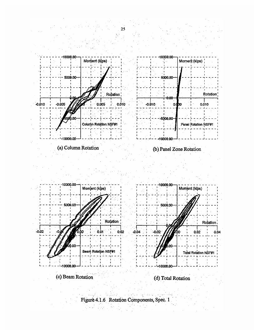
Figure 4.1.6 Rotation Components, Spec. 1 ....................................................................... 25
(a) Column Rotation
(b) Panel Zone Rotation
(c) Beam Rotation
(d) Total Rotation
Figure 4.1.7 Beam Top Flange Strain, Spec. 1 ................................................................... 26
(a) Right Edge
(b) Left Middle
Figure 4.1.8 Beam Bottom Flange Strain, Spec. 1 .............................................................. 27
(a) Center
(b) Right Middle
(c) Right Edge
(d) Left Middle
Figure 4.1.9 Panel Zone Strains, Spec. 1 ............................................................................ 28
viii
(a) Center Gage, Vertical
(c) Right Gage, 45o
(d) Principal Strain
(e) Principal Strain
Figure 4.2.1 Weld Detail, Weld Replacement .................................................................... 29
Figure 4.2.2 Repaired Bottom Flange Weld, Spec. 1R ...................................................... 30
Figure 4.2.3 Cyclic Behavior, Spec. 1R ............................................................................. 31
(a) Moment vs. Total Rotation
(b) Moment vs. Plastic Rotation
(c) Beam Tip Displacement
(d) Beam Tip Force
Figure 4.2.4 Crack in Top Flange of Beam, 1R ................................................................. 32
Figure 4.2.5 Plastic Hinge in Beam, 1R.............................................................................. 32
Figure 4.2.6 Rotation Components, Spec. 1R ..................................................................... 33
(a) Column Rotation
(b) Panel Zone Rotation
(c) Beam Rotation
(d) Total Rotation
Figure 4.2.7 Panel Zone Strains, Spec. 1R ......................................................................... 35
(a) Left Gage, 45o
(b) Center Gage, Vertical
(c) Right Gage, 45o
(d) Principal Strain
(e) Principal Strain
Figure 4.2.8 Comparative Behavior (1 & 1R) .................................................................... 36
Figure 4.3.1 Calculated Force vs. Displ., Spec. 2 ............................................................... 37
Figure 4.3.2 Calculated Stress Contours, Spec. 2 ............................................................... 38
Figure 4.3.3 Bottom Flange Pullout, Spec. 2 ..................................................................... 39
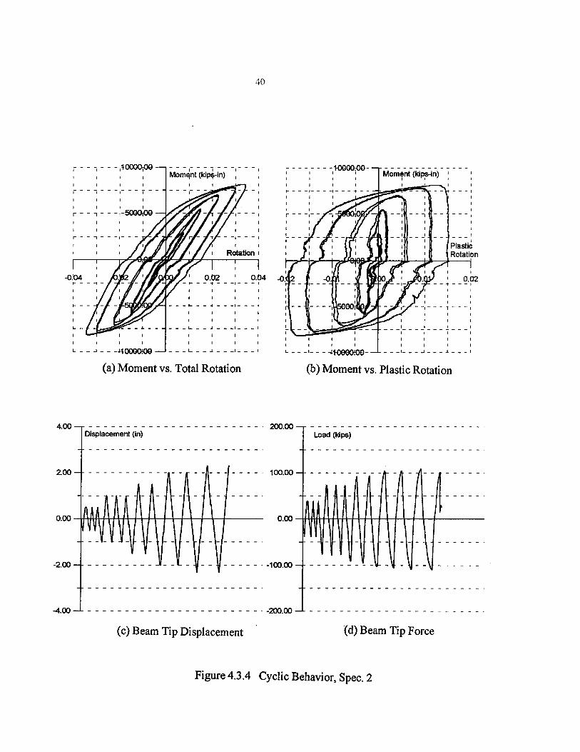
Figure 4.3.4 Cyclic Behavior, Spec. 2 ................................................................................ 40
(a) Moment vs. Total Rotation
(b) Moment vs. Plastic Rotation
(c) Beam Tip Displacement
(d) Beam Tip Force

ix
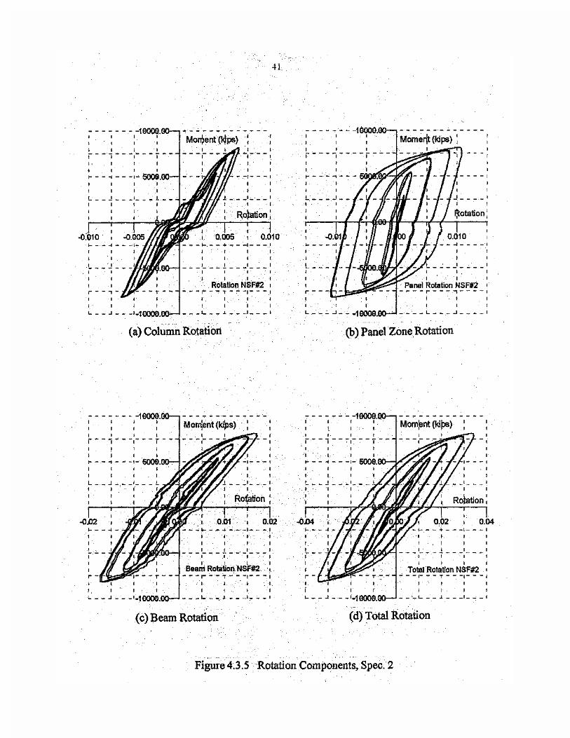
Figure 4.3.5 Rotation Components, Spec. 2........................................................................ 41
(a) Column Rotation
(b) Panel Zone Rotation
(c) Beam Rotation
(d) Total Rotation
Figure 4.3.6 Beam Bottom Flange Strains, Spec. 2 ............................................................... 43
(a) Center
(b) Middle Right
(c) Edge Right
(d) Edge Left
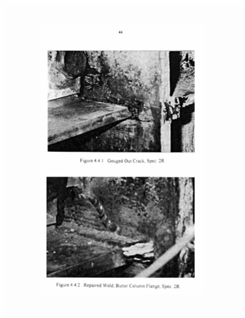
Figure 4.4.1 Gouged Out Crack, Spec. 2R ......................................................................... 44
Figure 4.4.2 Buttered Weld, Column Flange, Spec. 2R ...................................................... 44
Figure 4.4.3 Beam Bottom Flange Fracture, Spec. 2R ...................................................... 45
Figure 4.4.4 Cyclic Behavior, Spec. 2R ............................................................................. 46
(a) Moment vs. Total Rotation
(b) Moment vs. Plastic Rotation
(c) Beam Tip Displacement
(d) Beam Tip Force
Figure 4.4.5 Rotation Components, Spec. 2R . ................................................................... 47
(a) Column Rotation
(b) Panel Zone Rotation
(c) Beam Rotation
(d) Total Rotation
Figure 4.4.6 Comparative Behavior (2 & 2R) .................................................................... 48
Figure 5.1.1 Detail of Solid Triangular Fin, Spec. 3 .......................................................... 50
Figure 5.1.2 Instrumentation Details, Spec. 3 .................................................................... 51
Figure 5.1.3 Calculated Force vs. Displ., Spec. 3 ............................................................... 52
Figure 5.1.4 Calculated Stress Contours, Spec. 3 ............................................................... 53
Figure 5.1.5 Fracture at Beam Top Flange, Spec. 3 ............................................................ 54
Figure 5.1.6 Formation of Plastic Hinge, Spec. 3 ............................................................. 54
Figure 5.1.7 Cyclic Behavior, Spec. 3 ................................................................................ 55
(a) Moment vs. Total Rotation
(b) Moment vs. Plastic Rotation

x
(c) Beam Tip Displacement
(d) Beam Tip Force
Figure 5.1.8 Rotation Components, Spec. 3 ....................................................................... 57
(a) Column Rotation
(b) Panel Zone Rotation
(c) Beam Rotation
(d) Total Rotation
Figure 5.1.9 Beam Flange Strains, Spec. 3 ......................................................................... 58
(a) Top Flange, Center
(b) Bottom Flange, Center
Figure 5.1.10 Panel Zone Strain, Spec. 3 ............................................................................. 59
(a) Left Gage, 45o
(b) Center Gage, Vertical
(c) Right Gage, 45o
(d) Principal Strain
(e) Principal Strain
Figure 5.1.11 Solid Fin Strain, Spec. 3 .................................................................................. 60
(a) Left Gage, 45o
(b) Center Gage, Vertical
(c) Right Gage, 45o
(d) Principal Strain
(e) Principal Strain
Figure 5.2.1 Perforated Fin Detail, Spec. 4 ........................................................................ 61
Figure 5.2.2 Test Specimen with Perforated Fins ............................................................... 61
Figure 5.2.3 Calculated Force vs. Displ., Spec. 4 ............................................................... 62
Figure 5.2.4 Calculated Stress Contours, Spec. 4 .............................................................. 63
Figure 5.2.5 Calculated Deformed Shape, Spec. 4 ............................................................. 65
Figure 5.2.6 Plastic Hinge, Spec. 4 ..................................................................................... 66
Figure 5.2.7 Cyclic Behavior, Spec. 4................................................................................. 67
(a) Moment vs. Total Rotation
(b) Moment vs. Plastic Rotation
(c) Beam Tip Displacement
(d) Beam Tip Force

xi
Figure 5.2.8 Rotation Components, Spec. 4........................................................... ............ 68
(a) Column Rotation
(b) Panel Zone Rotation
(c) Beam Rotation
(d) Total Rotation
Figure 5.2.9 Beam Top Flange Strains, Spec. 4 ......................................................... ........ 69
(a) Back Left
(b) Front Left
Figure 5.2.10 Beam Bottom Flange Strains, Spec. 4 ............................................................. 70
(a) Front Center
(b) Front Left
Figure 5.2.11 Panel Zone Strains, Spec. 4 ............................................................................. 71
(a) Left Gage, 45o
(b) Center Gage, Vertical
(c) Right Gage, 45o
(d) Principal Strain
(e) Principal Strain
Figure 5.3.1 Calculated Load vs. Displ., Spec. 6 ................................................................ 73
Figure 5.3.2 Calculated Stress Contours, Spec. 6 .............................................................. 74
Figure 5.3.3 Calculated Deformed Shape, Spec. 6 ...... 75
Figure 5.3.4 Pullout at Beam Bottom Flange, Spec. 6 .. 76
Figure 5.3.5 Crack in Panel Zone, Spec. 6 .......................................................................... 76
Figure 5.3.6 Cyclic Behavior, Spec. 6 ................................................................................ 77
(a) Moment vs. Total Rotation
(b) Moment vs. Plastic Rotation
(c) Beam Tip Displacement
(d) Beam Tip Force
Figure 5.3.7 Rotation Components, Spec. 6........................................................................ 78
(a) Column Rotation
(b) Panel Zone Rotation
(c) Beam Rotation
(d) Total Rotation
Figure 5.3.8 Beam Bottom Flange Strains, Spec. 6 .............................................................. 80

xii
(a) Front Center
(b) Front Right
(c) Back Left
(d) Back Right
Figure 5.3.9 Beam Top Flange Strains, Spec. 6 .................................................................... 81
(a) Back Left
(b) Back Right
(c) Front Left
(d) Front Center
Figure 5.3.10 Panel Zone Strains, Spec. 6 .............................................................................. 82
(a) Left Gage, 45o
(b) Center Gage, Vertical
(c) Right Gage, 45o
(d) Principal Strain
(e) Principal Strain
Figure 6.1.1 Specimen Details with Flange Plates .............................................................. 84
Figure 6.1.2 Modified Test Specimen #5.............................................................................. 85
Figure 6.1.3 Instrumentation Details, Spec. 5....................................................................... 86
Figure 6.1.4 Calculated Load vs. Displ., Spec. 5.................................................................. 87
Figure 6.1.5 Calculated Stress Contours, Spec. 5 ................................................................. 88
Figure 6.1.6 Cyclic Behavior, Spec. 5 ................................................................................. 89
(a) Moment vs. Total Rotation
(b) Moment vs. Plastic Rotation
(c) Beam Tip Displacement
(d) Beam Tip Force
Figure 6.1.7 Plastic Hinge, Spec. 5 ...................................................................................... 91
Figure 6.1.8 Flange Buckle, Spec. 5 ..................................................................................... 91
Figure 6.1.9 Rotation Components, Spec. 5 ......................................................................... 92
(a) Column Rotation
(b) Panel Zone Rotation
(c) Beam Rotation
(d) Total Rotation
Figure 6.1.10 Beam Bottom Flange Strains, Spec. 5 .............................................................. 93

xiii
(a) Front Center
(b) Front Right
(c) Back Center
(d) Back Left
Figure 6.1.11 Top Flange Plate Strains, Spec. 5 .................................................................... 94
(a) Back Left
(b) Back Center
(c) Back Right
Figure 6.1.12 Beam Top Flange Strains, Spec. 5 ................................................................... 95
(a) Front Center
(b) Front Right
Figure 6.1.13 Column Flange Strain, Spec. 5 ........................................................................ 95
Figure 6.1.14 Panel Zone Strains, Spec. 5 ............................................................................. 96
(a) Left Gage, 45o
(b) Center Gage, Vertical
(c) Right Gage, 45o
(d) Principal Strain
(e) Principal Strain
Figure 6.2.1 Calculated Load vs. Displ., Spec. 7.................................................................. 97
Figure 6.2.2 Calculated Stress Contours, Spec. 7 ................................................................. 99
Figure 6.2.3 Calculated Deformed Shape, Spec. 7 .............................................................. 100
Figure 6.2.4 Cyclic Behavior, Spec. 7 ................................................................................. 101
(a) Moment vs. Plastic Rotation
(c) Beam Tip Displacement
(d) Beam Tip Force
Figure 6.2.5 Plastic Hinge Initiation, Spec. 7 ..................................................................... 102
Figure 6.2.6 Panel Zone Deformation, Spec. 7 ................................................................... 102
Figure 6.2.7 Rotation Components, Spec. 7 ........................................................................ 103
(a) Column Rotation
(b) Panel Zone Rotation
(c) Beam Rotation
(d) Total Rotation
Figure 6.2.8 Top Flange Plate Strains, Spec. 7 ............................................................. ....... 104

xiv
(a) Center
(b) Right Middle
(c) Right Edge
(d) Left Middle
(e) Left Edge
Figure 6.2.9 Beam Top Flange Strains, Spec. 7........................................................... ........ 105
(a) Center
(b) Right Middle
(c) Right Edge
Figure 6.2.10 Bottom Flange Plate Strains, Spec. 7 ............................................................. 107
(a) Center
(b) Right Middle
(c) Right Edge
Figure 6.2.11 Beam Bottom Flange Strains, Spec. 7 ............................................................. 108
(a) Center
(b) ight Middle
(c) Right Edge
Figure 6.2.12 Column Flange Strains, Bottom, Spec. 7 ........................................................ 109
(a) Center
(b) Right Middle
(c) Right Edge
Figure 6.2.13 Column Flange Strains, Top, Spec. 7 ........................................................ ..... 110
(a) Center
(b) Right Middle
(c) Right Edge
Figure 6.3.1 Calculated Load vs. Displ., Spec. 8 ........................................................... ..... 111
Figure 6.3.2 Calculated Stress Contours, Spec. 8 ........................................................... ..... 112
Figure 6.3.3 Test Specimen with Miniplate ............................................................ ............ 114
Figure 6.3.4 Cyclic Behavior, Spec. 8 ................................................................ ................ 115
(a) Moment vs. Total Rotation
(b) Moment vs. Plastic Rotation
(c) Beam Tip Displacement
(d) Beam Tip Force

xv
Figure 6.3.5 Plastic Hinge and Flange Buckle ......... 116
Figure 6.3.6 Rotation Components, Spec. 8 ............................................................ ............ 117
(a) Column Rotation
(b) Panel Zone Rotation
(c) Beam Rotation
(d) Total Rotation
Figure 6.3.7 Front Top Flange Strains, Spec. 8 ............................................................. ....... 118
(a) Right Middle
(b) Right Edge
(c) Left Edge
Figure 6.3.8 Back Top Flange Strains, Spec. 8............................................................. ........ 119
(a) Center Miniplate
(b) Right Middle Miniplate
(c) Right Edge
(d) Left Middle Miniplate
(e) Left Edge
Figure 6.3.9 Front Bottom Flange Strains, Spec. 8.......................................................... .... 120
(a) Right Middle
(b) Right Edge
Figure 6.3.10 Back Bottom Flange Strains, Spec. 8 ............................................................. 121
(a) Center Miniplate
(b) Right Middle Miniplate
(c) Right Edge
Figure 6.3.11 Panel Zone Rosette, Spec. 8 ........................................................................... 122
(a) Left Gage, 45o
(b) Center Gage, Vertical
(c) Right Gage, 45o
(d) Principal Strain
(e) Principal Strain
Figure 6.4.1 Calculated Load vs. Displ., Spec. 9.................................................................. 124
Figure 6.4.2 Calculated Stress Contours, Spec. 9 ........................................................... ..... 125
Figure 6.4.3 Specimen With Single Flange Plate ......................................................... ....... 126
xvi
Figure 6.4.4 Cyclic Behavior, Spec. 9 ................................................................ ................ 127
(a) Moment vs. Total Rotation
(b) Moment vs. Plastic Rotation
(c) Beam Tip Displacement
(d) Beam Tip Force
Figure 6.4.5 Crack in Top Flange of Beam ......................................................................... 128
Figure 6.4.6 Rotation Components, Spec. 9 ........................................................... ............ 129
(a) Column Rotation
(b) Panel Zone Rotation
(c) Beam Rotation
(d) Total Rotation
Figure 6.4.7 Beam Top Flange Strains, Spec. 9.................................................................... 130
(a) Center
(b) Right Edge
Figure 6.4.8 Beam Bottom Flange Strains, Spec. 9 ............................................................. 131
(a) Center
(b) Right Middle
(c) Right Edge
(d) Left Middle
(e) Left Edge
Figure 6.4.9 Column Flange Strains, Spec. 9 ..................................................................... 133
(a) Center
(b) Right Middle
(c) Right Edge
Figure 6.4.10 Panel Zone Strains, Spec. 9 ............................................................................ 134
(a) Left Gage, 45o
(b) Center Gage, Vertical
(c) Right Gage, 45o
(d) Principal Strain
(e) Principal Strain
Figure 7.1.1 Calculated Load vs. Displ., Spec. 12 ............................................................... 136
Figure 7.1.2 Calculated Stress Contours, Spec. 12 .............................................................. 137

xvii
Figure 7.1.3 Cyclic Behavior, Spec. 12 ................................................................................ 138
(a) Moment vs. Total Rotation
(b) Moment vs. Plastic Rotation
(c) Beam Tip Displacement
(d) Beam Tip Force
Figure 7.1.4 Crack at Beam Bottom Flange, Spec. 12.......................................................... 139
Figure 7.1.5 Crack in Panel Zone, Spec. 12 ......................................................................... 139
Figure 7.1.6 Rotation Components, Spec. 12 ....................................................................... 140
(a) Column Rotation
(b) Panel Zone Rotation
(c) Beam Rotation
(d) Total Rotation
Figure 7.2.1 Class A Repair Detail ...................................................................................... 142
Figure 7.2.2 Gouged Out Weld, Top Side, Spec. 10 ............................................................ 143
Figure 7.2.3 Gouged Out Weld, Bottom Side, Spec. 10 ................................................... ... 143
Figure 7.2.4 Overlay Weld, Bottom Flange, Spec. 10 ......................................................... 144
Figure 7.2.5 Cyclic Behavior, Spec. 10 ................................................................................ 145
(a) Moment vs. Total Rotation
(b) Moment vs. Plastic Rotation
(c) Beam Tip Displacement
(d) Beam Tip Force
Figure 7.2.6 Panel Zone Deformation, Spec. 10................................................................... 146
Figure 7.2.7 Initial Top Flange Crack, Spec. 10 .................................................................. 146
Figure 7.2.8 K-Line Slit, Bottom Flange, Spec. 10 ........................................................ ..... 148
Figure 7.2.9 Crack Across Beam Top Flange, Spec. 10 ................................................... ... 148
Figure 7.2.10 Rotation Components, Spec. 10 ......................................................... ............ 149
(a) Column Rotation
(b) Panel Zone Rotation
(c) Beam Rotation
(d) Total Rotation
Figure 7.3.1 Calculated Load vs. Displ., Spec. 11................................................................ 150
Figure 7.3.2 Calculated Stress Contours, Spec. 11 ............................................................... 151
Figure 7.3.3 Cyclic Behavior, Spec. 11 ................................................................................ 152
(a) Moment vs. Total Rotation

xviii
(b) Moment vs. Plastic Rotation
(c) Beam Tip Displacement
(d) Beam Tip Force
Figure 7.3.4 Crack in HAZ, Top Flange, Spec. 11 ............................................................... 153
Figure 7.3.5 Rotation Components, Spec. 11 ....................................................................... 154
(a) Column Rotation
(b) Panel Zone Rotation
(c) Beam Rotation
(d) Total Rotation
Figure 7.3.6 Beam Top Flange Strains, Spec. 11.................................................................. 156
(a) Center
(b) Right Middle
(c) Right Edge
(d) Left Middle
(e) Left Edge
Figure 7.3.7 Beam Bottom Flange Strains, Spec. 11 ........................................................... 157
(a) Left Middle
(b) Left Edge
Figure 7.3.8 Panel Zone Strains, Spec. 11 ........................................................................... 158
(a) Left Gage, 45o
(b) Center Gage, Vertical
(c) Right Gage, 45o
(d) Principal Strain
(e) Principal Strain
Figure 7.4.1 Class C Overlay Detail, Spec. 14 ..................................................................... 159
Figure 7.4.2 Overlay Weld at Top Flange, Spec. 14 ............................................................. 160
Figure 7.4.3 Overlay Weld at Bottom Flange, Spec. 14 ....................................................... 160
Figure 7.4.4 Cyclic Behavior, Spec. 14 ................................................................................ 161
(a) Moment vs. Total Rotation
(b) Moment vs. Plastic Rotation
(c) Beam Tip Displacement
(d) Beam Tip Force
Figure 7.4.5 K-Line Slit, Top Flange, Spec. 14 ........................................................... ........ 164

xix
Figure 7.4.6 K-Line Slit, Bottom Flange, Spec. 14 ............................................................. 164
Figure 7.4.7 Buckled Flange Fracture, Spec. 14................................................................... 165
Figure 7.4.8 Bolt Slippage, Flange Buckle, Spec. 14 ........................................................... 165
Figure 7.4.9 Rotation Components, Spec. 14 ...................................................................... 166
(a) Column Rotation
(b) Panel Zone Rotation
(c) Beam Rotation
(d) Total Rotation
Figure 7.4.10 Beam Bottom Flange Strains, Spec. 14 .......................................................... 167
(a) Center
(b) Right Edge
Figure 7.4.11 Beam Top Flange Strains, Spec. 14................................................................. 167
(a) Left Edge
(b) Center
Figure 7.5.1 Comparative Behavior (#11 & #12) ................................................................ 168
Figure 7.5.2 Comparative Behavior (#10 & #12) ................................................................ 169
Figure 7.5.3 Comparative Behavior (#11 & #14) ................................................................ 169
Figure 8.1.1 Reduced Beam Section, "Dogbone" ................................................................ 171
Figure 8.1.2 Instrumentation Details, Spec. 13..................................................................... 172
Figure 8.1.3 Cyclic Behavior, Spec. 13 ............................................................................... 173
(a) Moment vs. Total Rotation
(b) Moment vs. Plastic Rotation
(c) Beam Tip Displacement
(d) Beam Tip Force
Figure 8.1.4 Crack in Beam Top Flange, Spec. 13 ............................................................... 174
Figure 8.1.5 Crack in Beam Top Flange, Spec. 13 .............................................................. 174
Figure 8.1.6 Yielding in Flange Perforations ....................................................................... 175
Figure 8.1.7 Plastic Hinge Formation, Spec. 13 ................................................................... 175
Figure 8.1.8 Top Flange Strains, Front, Spec. 13 ................................................................. 177
(a) Center
(b) Middle Right
(c) Middle Left
Figure 8.1.9 Top Flange Strains, Middle, Spec. 13 .............................................................. 178
(a) Middle Right

xx
(b) Middle Left
Figure 8.1.10 Top Flange Strains, Back, Spec. 13................................................................. 178
(a) Middle Right
(b) Middle Left
Figure 8.1.11 Rotation Components, Spec. 13 ..................................................................... 179
(a) Column Rotation
(b) Panel Zone Rotation
(c) Beam Rotation
(d) Total Rotation
Figure 8.1.12 Comparative Behavior (#11 & #13) . .............................................................. 180
Figure 8.2.1 Specimen 15 With Web Windows .................................................................... 181
Figure 8.2.2 Test Specimen in Reaction Frame .................................................................... 183
Figure 8.2.3 Cyclic Behavior, Spec. 15 ............................................................................... 184
(a) Moment vs. Total Rotation
(b) Moment vs. Plastic Rotation
(c) Beam Tip Displacement
(d) Beam Tip Force
Figure 8.2.4 Buckled Beam Flange and Web, Spec. 15........................................................ 185
Figure 8.2.5 Rotation Components, Spec. 15 ...................................................................... 186
(a) Column Rotation
(b) Panel Zone Rotation
(c) Beam Rotation
(d) Total Rotation
Figure 8.2.6 Column Web Panel Zone Strains, Spec. 15...................................................... 187
(a) Left Gage, 45o
(b) Center Gage, Vertical
(c) Right Gage, 45o
(d) Principal Strain
(e) Principal Strain
Figure 8.2.7 Column Web Doubler Strains, Spec. 15........................................................... 188
(a) Left Gage, 45o
(b) Center Gage, Vertical
(c) Right Gage, 45o

xxi
(d) Principal Strain
(e) Principal Strain
Figure 8.2.8 Panel Zone Window Strains, Spec. 15 ............................................................ 190
(a) Left Gage, 45o
(b) Center Gage, Vertical
(c) Right Gage, 45o
(d) Principal Strain
(e) Principal Strain
Figure 8.2.9 Beam Web Window Strains, Spec. 15 .............................................................. 191
(a) Left Gage, 45o
(b) Center Gage, Vertical
(c) Right Gage, 45o
(d) Principal Strain
(e) Principal Strain
Figure 8.2.10 Beam Flange Strains, Spec. 15 ....................................................................... 192
(a) Center Flange
(b) Edge Flange, Left
(c) Middle Flange, Right
(d) Edge Flange, Right
Figure 8.2.11 Column Web Strains Near Windows ............................................................... 193
(a) Gage #1
(b) Gage #2
(c) Gage #3
(d) Gage #4
Figure 8.2.12 Column Strains, Back Flange.......................................................................... 194
(a) Above Top Continuity Plate
(b) Below Bottom Continuity Plate
Figure 8.2.13 Column Web Strain Above Continuity Plate .................................................. 194
Figure 9.0.1 Results Summary ............................................................................................. 196
(a) Total Rotation and Plastic Rotation
(b) Moment Ratio and Ductility Ratio

1
1.0 INTRODUCTION
1.1 Overview and Problem Description
One of the more significant issues to arise from the Northridge earthquake (1994) was the detec-
tion of cracking in welded beam to column connections of modern steel buildings [1]. In most
cases, these connections are hidden from view by spray-on fire-proofing and nonstructural build-
ing partitions making them inaccessible for direct visual inspection. In many cases there was no
immediate visual sign of damage to the buildings and they were green-tagged for immediate occu-
pancy. Only after the cracking problem was noticed in buildings that were either under construc-
tion or suffered severe distortion in the structural frame did closer inspection reveal connection
damage in a significant number of buildings.
The most common type of cracking observed in the buildings appears to start in the weld at
the center of the bottom beam flange. This is a region of high stress concentration due to the
increased stiffness caused by the column web and beam web. It is also a region of discontinuous
welds. Current practice dictates that welds be made in the down-hand position (ie. the welding
instrument is pointed downward to make the weld). At the top flange, the weld can be made in a
continuous pass since there is no beam web to get in the way. However, the weld at the bottom
beam flange has to pass through the beam web. This is done by cutting an access hole (web cope
hole) in the beam web and then placing the weld from the beam web to the edge of the flange on
each side. This procedure causes the weld at the center of the beam to be subject to porosity and
slag inclusions which combined with high stress creates a region that is prone to crack initiation.
Both top and bottom beam flange welds use a thin steel bar (backup bar) to close the gap
between the beam flange and the column flange. This bar is usually tack welded into place to keep
the weld metal from running down the face of the column flange. Pre-Northridge connections left
this backup bar in place after the full penetration welds between the column flange and the beam
flange were completed. Recognizing that this was also a source of porosity and slag inclusions,
the SAC Joint Venture [2] recommended that these bars be removed after the welding was com-
pleted for post-Northridge connections.
The web cope hole itself is a significant source of crack initiation. The geometry and surface
quality of these holes varies considerably. Often they are flame cut to no specific geometry and
are not ground smooth. This gives rise to a rough surface located in a high stress region which is
ideal for crack initiation. This is particularly true when the beam flanges begin to buckle under
cyclic loading and plastic hinging. It is of interest to note that the Japanese require that web copes
be machine cut to a specified geometry. However, cracks initiating from the web cope were still
2
observed in the connection inspections following the Kobe earthquake, therefore, it is does not
appear that this additional fabrication alone will solve the problems associated with the web cope.
The use of overhead welding (ie. the welding instrument is pointed upward to make the weld)
would eliminate the need for a web cope and thereby eliminate the problems associated with it.
Although some welding engineers claim there is no difficulty making an overhead weld in the
field, others claim that this procedure is not economical and hence there is currently no clear con-
sensus on the use of this welding procedure. Therefore, it must be assumed that the web cope will
continue to be used in these connections and ways to neutralize its negative effects must be devel-
oped as part of any repair/retrofit scheme.
1.2 Objective and Scope
The poor performance of welded beam to column moment connections during the Northridge
earthquake placed a priority on developing cost effective means of repairing damaged connections
in existing buildings and evaluating alternative modifications for improving connection behavior
in new construction. In addition, economic procedures had to be developed for upgrading the
resistance of welded connections in existing buildings. In order to contribute to this effort, an inte-
grated analytical and experimental study was initiated. The following objectives were developed
for the initial investigation:
(a) Evaluate the yielding mechanisms and failure modes of existing "standard" welded
moment connections.
(b) Investigate the influence of the column panel zone on connection behavior.
(c) Investigate the application of new welding techniques such as "weld overlay" on connec-
tion performance.
(d) Evaluate cost effective connection modifications for improving cyclic performance with
emphasis on procedures not being evaluated by other investigators.
(e) Conduct parallel investigations using nonlinear finite element analysis to establish a co-
relation between the results of finite element models and the experimental test specimens.

3
1.3 Approach
In order to accomplish the above objectives, a series of experimental investigations, coupled with
finite element analyses were undertaken. Due to constraints on laboratory access, test frame
capacity and cost, it was necessary to use connection specimens that are representative of either
low rise structures or the upper stories of mid-rise steel construction. It should also be noted that
other researchers were in the process of evaluating the performance of large size connection spec-
imens [3, 4, 5, 6, 7] and hence this study did not duplicate their efforts.
The repair/upgrade procedures considered in this study can be grouped into the following
main categories: (a) weld replacement, (b) horizontal flange plates, (c) vertical flange plates, (d)
weld overlay and (e) other procedures including beam flange perforation and web access win-
dows. These methods are discussed briefly in the following paragraphs:
1.3.1 Weld Replacement
Perhaps the easiest way to repair a crack in the weld material at a connection is to remove the
backup bars at the bottom of the flange welds, remove the existing weld material and reweld using
a notch tough (ductile) weld material. The backup bar is removed and a reinforcing fillet weld is
placed at the root of the weld. It may also be necessary to weld the shear tab to the beam web.
1.3.2 Horizontal Flange Plates
Another common method of improving the behavior of welded moment connections is the addi-
tion of reinforcing flange plates to the connection. The purpose of the flange plates is threefold.
First, the centroid of the reinforced section is moved further from the neutral axis of the beam
section so that the moment capacity is increased. Second, with the increased moment capacity due
to the addition of the plates, inelastic behavior (plastic hinging) is moved away from the connec-
tion region and in particular away from the crack sensitive web cope region. Third, the increased
beam flange thickness at the column flange reduces the stress concentration.
In this study, the flange plate is the same width and thickness as the beam flange. The sides of
the plate are beveled to permit a partial penetration groove weld along the sides instead of the
more common fillet weld. The connection to the column is made with a full penetration grove
weld and a fillet weld is applied to the opposite end. The existing weld flux core arc weld
(FCAW) was ground flush with the top (bottom) flange of the beam to accommodate the beveled
plate. A full penetration weld using shielded metal arc weld (SMAW) connected the flange plate
to the column flange. Hence the existing FCAW weld was overlayed with SMAW. The connection
at the end of the flange plate was made with a 5/8 inch fillet weld. At the bottom flange, the plate

4
is welded in the overhead position, allowing the entire weld to be made without interruption. The
standard flange plates for these tests are 8 inches wide by 14 inches long by 3/4 inches thick. For
one specimen a half size (miniplate) was used which was 4 inches wide by 7 inches long by 3/4
inches thick. For another specimen, a single, full sized flange plate was welded to only the bottom
flange of the beam.
1.3.3 Vertical Triangular Plates
A third type of repair/retrofit detail is the addition of a vertical triangular plate (fin) above the top
beam flange and below the bottom beam flange, in line with the beam web. This diverts some to
the force in the beam flange around the connection to the column flange. Stresses in the welds are
reduced by the additional weld material and by the resulting increase in the reactive moment arm
of the modified connection. Following an initial test on a solid fin, it was decided that the perfor-
mance might be improved by placing a hole in the fin. The purpose of the hole was to move the
critical section of the fin from the face of the column to the section through the hole. In this man-
ner, yielding occurs at the hole and thereby limits the amount of force transmitted to the welds at
the column flange.
1.3.4 Weld Overlay
A more recently developed procedure which can be used for either repair or upgrading a connec-
tion is accomplished by removing only a portion of the existing FCAW weld material on the top
and bottom beam flanges and placing a higher quality weld over the remaining weld material
(weld overlay). The existing weld may contain small cracks or indications of cracks and other
defects, some of which may be non-detectable even with the most sensitive testing methods. The
overlay must be able to immobilize existing defects in the weld material, heat affected zone
(HAZ) and parent material and at the same time to exert a positive influence on the web cope and
k-line regions.
1.3.5 Other Procedures
The use of a reduced beam section (RBS) to protect the beam to column connection region has
been reported by other investigators [8]. The RBS is usually formed by removing part of the beam
flanges with a cutting torch. The geometry of the removed flange section may be a constant cut, a
radius cut or a tapered cut. This moves the location of the plastic hinge away from the connection
to the reduced section and also limits the flange force that can be transmitted into the connection.
This procedure has been shown to work very well and has been used for new construction [9]. In
this study, this concept was applied to the retrofit of connections in existing buildings.

5
More recently studies have been conducted on using drilled holes to perforate the beam flange
in a similar manner to the RBS and thereby reduce the effective section away from the connection.
This method is attractive for the retrofit of connections in existing buildings since a heat source is
not required. One of the major costs in the repair/retrofit of existing connections is the setup of the
work space including the necessary fire protection. Use of a perforated beam flange will greatly
reduce the total cost of connection retrofit while providing the advantages of the flame cut flange.
For welded connections in moment frames located on the exterior of the building, it is usually
necessary to cut rectangular windows in the webs of the beam and column framing into the joint
to access the welds from the interior side. This procedure has been widely used for the repair of
damaged moment connections following the Northridge earthquake. When the repair is com-
pleted, a steel plate is welded over the window to seal the cutout. The effect of these windows on
the cyclic performance of a large scale test specimen is evaluated.

6
2.0 FINITE ELEMENT ANALYSES
Finite element analyses are used to gain better insight into the behavior of welded beam to column
connections and in particular to evaluate the effect of various connection modifications prior to
experimental testing. They can also be used to give direction to the testing program by estimating
the force requirements needed to reach given displacement limits. Although some information
regarding the location of regions of high stress (stress concentration) can be obtained from a linear
elastic analysis, substantial redistribution of stress occurs once the material yields. Therefore, it is
preferable to use a nonlinear analysis procedure which considers both material and geometrical
nonlinearities since at ultimate load, the connection specimen should experience strong material
nonlinearity and possible geometric nonlinearity as well. However, it must be recognized that the
complexities of the prototype connection preclude consideration of effects such as workmanship
and initial stresses due to rolling and welding. Also, the experimental specimen contains pinned
connections each of which has clearance tolerances necessary for installation. These conditions
are difficult if not impossible to include in the analytical model and hence will introduce some
discrepancy in the comparison of results.
Detailed finite element analyses were conducted on the welded beam to column connection
specimens tested as part of this study. Dimensions of the analytical models are identical to those
of the test specimens. Since the thicknesses of the beam and column sections used in the testing
program are all less than one inch, thick shell elements are used to represent all of the connection
and member components. This permits a substantial saving in compute time when compared to
using solid elements as required for the large connection specimens. Yielding is determined using
the "Von Mises" yield criteria. The analyses consider both material and geometric nonlinearity
under monotonically increasing load at the end of the beam. In this manner the so called "back-
bone" curve of the hysteresis curve is obtained.
The analyses were conducted using the COSMOS/M [10] computer program running on a
Hewlett Packard LM 5/60 computer with a 60 MHz pentium processor. The connection specimen
was modeled using a 4-node quadrilateral, thick shell element having six degrees of freedom per
node. A representative finite element model of an exterior moment connection with vertical fins is
shown in Figure 2.1. A typical model consisted of 1697 nodes and 1014 elements. Shear deforma-
tion effects are considered. Material plasticity is modeled using the Von-Mises elasto-plastic
model with kinematic hardening. A force control procedure was used to control the progress of the
computations along the equilibrium path of the system. In adapting this technique, the loads are


8
3.0 EXPERIMENTAL SYSTEM
3.1 General
The location of the structural engineering laboratory in a sub-basement, places a limitation on the
size of test specimen that can be used. Specimens representative of low rise frames can be fabri-
cated outside the laboratory and moved inside for testing. Specimens representative of mid-rise
structures can be tested in the laboratory but must also be fabricated in the laboratory due to clear-
ance limitations in moving the specimen from the surface. Large size components are beyond the
capabilities of the test frames. Smaller specimens also have a lower capital cost both for material
and fabrication. For these reasons it was necessary to test small size specimens representative of
low rise steel construction. The basic specimens were fabricated by a local steel fabricator and
then moved into the laboratory for testing. Modifications and repairs to the basic specimens were
done in the laboratory by a licensed welder. Welding by the fabricator was done using FCAW with
E70T-4 wire, whereas welding in the laboratory was done with SMAW using E7018 electrodes.
3.2 Experimental Setup
The load frame used for these tests is a self reacting load frame that can apply an axial compres-
sion load to the column in combination with a cyclic load at the beam tip. The tee shaped exterior
connection specimen is tested with the column vertical as shown in Figure 3.1. The column is
pinned at both ends of a nine foot height. Reactions from the applied beam moment are transmit-
ted by pin ended "A" frames to a reaction frame. Axial compression load is applied to the top of
the column by two 400 kip Simplex hydraulic cylinders acting on a two inch loading platen. Pres-
sure to drive these cylinders is developed by an Enerpac PAM-3025 air/oil hydraulic pump which
produces a constant compression load applied to the top of the column throughout the test, repre-
sentative of gravity load. Vertical, column loads are reacted through the frame by four, 4 inch
diameter, high strength steel rods spanning between two 12 inch thick steel blocks.
The cyclic load at the beam tip is applied by a 235 kip Atlas hydraulic cylinder.
A 300 kip tension/compression load cell is connected to the end of the cylinder
plunger. A rod-eye mounted on the top of the load cell is connected by a 3 inch
diameter pin to a clevis which is bolted to the beam end plate with 4 - 1 3/4 inch
diameter bolts. The cylinder is connected through another clevis to the test frame.
Motion of the cylinder is controlled by a closed-loop servo system. Pressure to drive


10
this cylinder is provided by a Fornaciari Power Unit which delivers 3.5 gallons/
minute at 3000 psi.
3.3 Instrumentation
Software running on a Hewlett Packard QS/20 computer controls the loading process and the data
acquisition. The data acquisition system con
sists of two Keithley/Metrabyte Series 500 data systems which are connected to the PC through
the parallel interface. A standard configuration has six LVDT channels, twenty four strain gage
channels and two control channels. The instrumentation and control setup is illustrated in Figure
3.2.
Labtech Notebook is the data acquisition and control software used for these tests. It has the
ability to control various hydraulic actuators and to acquire data from strain gage and LVDT data
acquisition boards. Since the tests are to evaluate specimen performance, the instrumentation
must monitor the loading history, overall displacement of the specimen and the local strains in the
critical regions of the specimen. A closed loop PID algorithm was adapted for displacement con-
trol of the actuator which controls the loading process of each test. Strain gage and LVDT chan-
nels are configured to collect data from installed instruments and gages.
Strains in the connection region were measured using general purpose gages with elongation
to ±20% (Micro Measurements Group, 250BG). Strains in the panel zone were measured using a
strain rosette with elongation to ±5% (Micro Measurements Group, 250UR). Deformations in the
panel zone and at the beam tip were measured using LVDTs.
3.4 Test Specimens
For the initial series of tests, eight test specimens were provided by the American Institute of Steel
Construction (AISC) and one additional specimen, which initially served as a mockup specimen,
was donated by Brown-Strauss Steel in Denver. All test specimens were fabricated at Lee and
Daniel with welded moment connections representative of pre-Northridge design practice. The
first two specimens were tested twice, once in the "as received" condition and then in the repaired
condition. The mockup specimen was also retrofitted and tested during the first series of tests.
This resulted in a total of eleven tests. All welding was visually inspected and all full penetration
welds between the beam flanges and the column flange were ultrasonically tested by an indepen-
dent testing company.


12
Test specimens for the first series of tests consisted of a W21x68 beam (A36 steel)
welded to a W12x106 column (A572-GR50). A typical detail is shown in Figure 3.3.
Five of the specimens were fabricated with a 1/2 inch doubler plate welded to one side of
the column web in the panel zone as shown in Figure 3.3a. This plate extended a dis-
tance of 8 inches on either side of the continuity plates. The other four specimens were
fabricated without the doubler as shown in the detail in Figure 3.3b.
Five additional specimens were provided by AISC which consisted of a W21x68 beam (A36)
welded to a W16x77 (A572-GR50). These specimens were fabricated in the same manner as
those discussed above. Three of these specimens had a 1/2 doubler plate welded to one side of the
column web in the panel zone (Figure 3.4a) and two were fabricated without the doubler (Figure
3.4b).
3.5 Material Properties
As mentioned previously, columns of the test specimens were ASTM A572-50 and beams were
ASTM A36. Material for the specimens was supplied by Nucor-Yamato Steel Co. from their
Armorel, Arkansas facility. Standard mill certification tests were conducted by the mill and cou-
pons taken from the fabricated specimens were tested by a commercial materials testing labora-
tory. Results of these tests are summarized in TABLE 1 . Mill certifications are listed for each of
the heats.
For the A36 steel, the mill certs indicate an average yield stress of more than 51,000 psi, how-
ever, the coupon tests result in an average of only 47,400 psi. The results for the G50 steel indicate
a yield stress of 50,000 psi based on the mill certification tests and an average of 55,800 based on
the coupon tests. A typical stress vs. strain curve for these materials based on nominal properties
is shown in Figure 3.5 for reference.
3.6 Test Program
The results of seventeen tests on large scale moment connections are described in this report. The
overall test program is summarized in TABLE 2 . Basic instrumentation common to all test speci-
mens is summarized in TABLE 3 and indicated on the individual test specimens which follow.


15
TABLE 1. MATERIAL PROPERTIES
____________________________________________________________
SPECIMEN Type Yield Tensile Elongation
Strength Strength at Fracture
____________________________________________________________
1 A36-Mill 52,000 72,000 27
2 A36-Mill 51,000 68,000 27
3 A36-Mill 51,000 68,000 28
4 G50-Mill 50,000 66,000 26
____________________________________________________________
5 A36 Flange 44,118 64,118 30
6 A36 Flange 45,181 65,964 38
7 A36 Web 52,968 67,580 38
8 A36 Web 47,393 65,877 34
____________________________________________________________
9 G50 Flange 53,162 77,075 30
10 G50 Flange 46,735 67,347 44
11 G50 Web 52,288 75,163 38
12 G50 Web 71,207 78,638 24
____________________________________________________________

16
TABLE 2. TEST PROGRAM
___________________________________________________________
SPECIMEN Characteristics
___________________________________________________________
1 Baseline W12x106 column, with doubler plate
1R Weld replacement repair of specimen #1
2 Baseline W12x106 column, without doubler plate
2R Weld replacement repair of specimen #2
3 Solid triangular fin without doubler plate
4 Perforated triangular fin with doubler plate
5 Dual flange plates with a doubler plate
6 Perforated triangular fin without doubler plate
7 Dual flange plates without a doubler plate
8 Dual miniplates with a doubler plate
9 Single flange plate with a doubler plate
10 Class A overlay repair without doubler plate
11 Baseline W16x77 column with doubler plate
12 Baseline W16x77 column without doubler plate
13 Perforated beam flange, W16x77 column with Doubler plate
14 Class C Overlay repair with doubler plate
15 Full scale specimen with web windows, W36x135 beam and
W30x173 column with web doubler
___________________________________________________________


18
4.0 WELD REPLACEMENT
4.1 Initial Test, Specimen #1
This specimen had a W12x106 column with a 1/2 inch doubler plate on one side of the web and a
W21x68 beam. The initial specimen was tested to failure in the "as received" condition.
Prior to testing, detailed nonlinear finite element analyses were conducted in an effort to esti-
mate the behavior of this specimen. The load-displacement envelope obtained from a static push
test is shown in Figure 4.1.1. This figure indicates a force of 120 kips at the beam tip is required
to develop a tip displacement of 3.2 inches, representative of a rotation of 4.8%. A color plot of
the Von Mises stress contours is shown in Figure 4.1.2. This figure shows that a plastic hinge has
formed at the column face, indicating high stresses in the welds at that location. It also indicates
that regions of high stress occur in the panel zone of the column with stresses above the nominal
yield stress of 50 ksi.
This initial specimen was tested to failure in the "as received" condition, repaired in the labo-
ratory and retested to failure. Twenty-seven channels of instrumentation were used for this speci-
men as shown in Figure 4.1.3. Three channels were used for control, seventeen were used for
strain gages, four for displacement measurements and three for the rosette in the panel zone.
The specimen sustained three displacement cycles at each amplitude of 1/2 inch, 1 inch and 1
1/4 inches. On the third cycle at a displacement amplitude of 1 1/2 inches, the specimen experi-
enced a pullout at the bottom beam flange (Figure 4.1.4) during an upward stroke of the hydraulic
cylinder. This type of failure is similar to those experienced by many welded moment frames dur-
ing the Northridge earthquake. The test was stopped at this point so that the specimen would not
be damaged beyond repair.
The cyclic performance of the specimen is summarized in Figure 4.1.5. The total rotation was
2.3 percent (Figure 4.1.5a), however, the plastic rotation was only 0.5 percent (Figure 1.5b). The
displacement history, shown in Figure 4.1.5c, indicates the nine displacement cycles the speci-
men was able to sustain. The history of the force at the beam tip, shown in Figure 4.1.5d, indi-
cates that there was no unloading of the specimen prior to failure suggesting a sudden type of
pullout. At a tip displacement of 1 1/2 inches, the finite element analysis estimated a force of 108
kips (Figure 4.1.1). This agrees very well with the 108 kips measured at the beam tip (Figure
4.1.5d).


24
The distribution of the rotation between the panel zone, column and beam is shown in Figure
4.1.6. It can be seen that the panel zone rotation is approximately 0.1%, the column is 0.6% and
the beam is 1.6 %. Measured strains in the top beam flange, shown in Figure 4.1.7 indicate a peak
strain of over 1.5% at the middle of the flange. Similar data for the bottom beam flange, Figure
4.1.8, indicates that at the four locations on the bottom flange, strains of 1.3 to 1.5% were
recorded. Strains in the panel zone, shown in Figure 4.1.9, indicate that the panel zone behavior
was linear elastic. The peak recorded strain was 0.13%.
4.2 Class B Repair, Specimen #1R
The Dynamic Load Weld (DLW) Task Group [11] has defined a Class B repair as one in which the
entire weld is gouged out and replaced with SMAW with a reinforcing fillet weld placed at the
root of the weld. A detail of the weld procedure is shown in Figure 4.2.1. The connection at the
bottom beam flange of Specimen #1 was repaired in this manner in the laboratory. The backup
bar was removed and all existing weld material was removed, including the heat affected zone of
the column flange. New weld material was placed using SMAW with E7018 electrodes and a
reinforcing fillet weld was added at the root of the weld. The repaired weld is shown in Figure
4.2.2. The shear tab was welded on three sides with a fillet weld. Since there was no visible dam-
age to the weld at the top flange, nothing was done to this weld. All welds were ultrasonically
tested and found to be sound. This specimen is referred to as Specimen 1R.
The cyclic behavior of the specimen after repair is summarized in Figure 4.2.3. It can be seen
that there is a significant increase in the deformation capacity of the connection. The connection
was able to sustain 17 cycles of increasing displacement (Figure 4.2.3c) and developed a total
rotation of 4.0% (Figure 4.2.3a). However, the plastic rotation increased to only 1.5% (Figure
4.2.3b), which is still not considered to be adequate. No unloading of the specimen occurred prior
to failure (Figure 4.2.3d). Failure occurred when a crack opened in the top beam flange (Figure
4.2.4). It can be seen that the crack appears to have started in the web cope and then propagated
across the beam flange. Whitewash on the beam indicated the formation of a plastic hinge as
shown in Figure 4.21.5. On the last full cycle, prior to failure, both the top and bottom beam
flanges buckled. The moment capacity was increased by 33%.
The rotation components for the repaired specimen are shown in Figure 4.2.6. This figure
indicates that the panel zone rotation is .25%, the column rotation is .62% and the beam rotation is
3.12% for a total of 4.0%. Since the panel zone remained elastic during the initial test, it was pos-
sible to measure strains at this location during the test in the repaired condition (Figure 4.2.7).
Strain measurements indicate that yielding occurred in the panel zone with strains reaching 0.5%.


34
Note that the weld at the top beam flange was made using FCAW with E70T-4 wire and the
one at the bottom was made using SMAW with E7018 electrode. Plots of the load versus dis-
placement hysteresis for the original test and for the repair test are compared in Figure 4.2.8. This
result tends to imply that if the welds on the "standard connection" are done properly and the
back-up bar is removed and replaced by a reinforcing fillet weld, the connection will perform in a
reasonable manner, at least for the smaller sections considered in this study.
4.3 Initial Test, Specimen #2
This specimen was similar to Specimen #1 except that the column did not contain a doubler plate
in the panel zone. The initial specimen was tested to failure in the "as received" condition.
Prior to testing, finite element analyses indicated a beam tip force of 100 kips would be
required to reach a 3 inch deflection as shown in Figure 4.3.1. Color contours of Von Mises
stresses, shown in Figure 4.3.2, indicate that the stresses in the beam are much lower than in the
previous case. The beam flanges have reached yield but a plastic hinge has not formed in the
beam. However, maximum stresses in the panel zone of the column have reached 56 ksi indicating
possible yielding.
Instrumentation was similar to that for specimen #1 (Figure 4.1.3). Failure of this specimen
was similar to the previous specimen with a sudden pullout occurring at the bottom beam flange
(Figure 4.3.3) during an upward stroke of the hydraulic cylinder. The brittle pullout at the bottom
flange of the beam also created a vertical crack that ran up the column flange.
The cyclic performance of the specimen is shown in Figure 4.3.4. The specimen was only
able to sustain 11 cycles of increasing displacement as shown in Figure 4.3.4c, reaching a maxi-
mum displacement of 2 1/4 inches which is representative of a total rotation of 3.4 percent (Fig-
ure 4.3.4a). The plastic rotation was approximately 1.52 percent as shown in Figure 4.3.4b. The
history of the load at the beam tip, shown in Figure 4.3.4d indicates there was no unloading of the
specimen prior to failure.
The distribution of the rotation components is shown in Figure 4.3.5. This figure indicates
that the panel rotation was 1.1%, the column rotation was 0.6% and the beam rotation was 1.7%
for a total rotation of 3.4%. Comparison with the similar data for specimen #1 indicates that most
of the increased rotation for specimen #2 is due to deformation of the panel zone. Strain measure-
ments at four locations across the bottom flange of the beam, shown in Figure 4.3.6, indicate that
peak strains were approximately 2.2 percent.


42
Unfortunately, strain data in the panel zone was lost for this specimen so a comparison with
the finite element solution cannot be made. At a tip displacement of 2 1/4 inches, the finite ele-
ment analysis predicted a beam tip force of 95 kips which is less than the 105 kips recorded.
4.4 Class B Repair, Specimen #2R
The connection pullout at the bottom flange of the beam was repaired in the laboratory using the
same Class B weld repair procedure as used for Specimen #1R (Figure 4.2.1). The crack in the
column flange was found to encompass about one-fourth the flange depth and to extend upward
for 1.5 inches. The entire crack area was gouged out as shown in Figure 4.4.1. Ductile weld mate-
rial (E7018) was "buttered" onto the column flange and the beam was rewelded to the column
(Figure 4.4.2). The shear tab was welded along the vertical side with just short returns at the top
and bottom. Since there was no visible damage to the weld at the top flange, nothing was done to
this weld. Unfortunately, it was not possible to ultrasonically test the repair welds before testing.
The increase in performance of the repaired specimen was not as dramatic as for specimen
#1R, being just slightly better than the initial connection. After repair, it was able to develop a
rotation capacity of 3.7 percent in both directions before the bottom flange of the beam failed sud-
denly by a brittle fracture. The crack appeared to start in the weld at the center of the beam flange
and then run along the weld in both directions until for about 2 inches. It then turned and ran
through the beam flange to the edge, encompassing about an inch of flange material. A crack also
developed in the shear tab and propagated along the centerline of the bolts for about half the
length of the shear tab. Both failures are shown in Figure 4.4.3.
The cyclic performance is summarized in Figure 4.4.4. The specimen was able to sustain 18
cycles of increasing displacement prior to failure (Figure 4.4.4c). The total rotation capacity was
3.7% (Figure 4.4.4a) of which 2.4% was plastic rotation as shown in Figure 2.8b. As indicated in
Figure 4.4.4d, there no unloading of the specimen prior to failure. The rotation components,
shown in Figure 4.4.5, indicate that the column rotation was .8%, the panel zone rotation was
1.3% and the beam rotation was 1.6% for a total of 3.7%. Plots of the load versus displacement
hysteresis for the original test (#2) and for the repair test (#2R) are compared in Figure 4.4.6.
Here it can be seen that the capacity of the repaired specimen is equal to that of the initial speci-
men.


49
5.0 VERTICAL FLANGE PLATES (FINS)
5.1 Solid Fin, Specimen #3
This specimen consists of a W21x68 beam welded to a W12x106 column with no doubler plate. A
single triangular plate (fin) in the plane of the beam web is welded on the top and bottom beam
flanges as shown in a detail of the fin, Figure 5.1.1. The instrumentation scheme used for the
specimens having a vertical fin is shown in Figure 5.1.2 indicating 32 channels of data acquisi-
tion.
Prior to testing, detailed nonlinear finite element analyses were conducted in an effort to esti-
mate the behavior of this specimen. The load-displacement envelope obtained from a static push
test is shown in Figure 5.1.3. This figure indicates a force of 130 kips at the beam tip is required
to develop a tip displacement of 3 inches. A color plot of the Von Mises stress contours is shown
in Figure 5.1.4. This figure shows that a plastic hinge is just beginning to form at the tip of the
vertical fin. It also indicates that regions of high stress occur in the fin near the column face. Pos-
sible yielding of the panel zone is also indicated with stresses above 50 ksi.
The specimen was subjected to 19 cycles of load and reached a total rotation of more than
4%. Initial failure was due to a pullout of the top fin from the weld at the face of the column. This
may have been due to a lack of complete fusion in the connecting weld or it may have been due to
the high stress transmitted through the fin to the column flange weld. The fin actually pulled out
of the weld material. This started to occur on the 17th cycle at a displacement of 2 3/4 inches. A
crack developed in the weld connecting the top fin to the column flange and extended about half
way (2 inches) down the fin. On the following cycle at the same displacement, the weld in the top
fin broke completely and a crack began in the corresponding weld in the bottom fin. On the next
cycle at a displacement of 3 inches, the original weld of the top beam flange to the column flange
fractured. The combined failure at the end of the test is shown in Figure 5.1.5 and the beginning
formation of a plastic hinge at the end of the fins is shown in Figure 5.1.6. The crack appeared to
start in the web cope of the beam web and then propagate across the beam flange.
The cyclic behavior of the specimen is summarized in Figure 5.1.7. The plot of moment ver-
sus rotation (Figure 5.1.7a) indicates a total rotation capacity of 4.5 percent with plastic rotation
of 2.5 percent as shown in Figure 5.1.7b. The displacement history, Figure 5.1.7c, indicates that
the specimen was capable of sustaining 18 cycles of increasing displacement, reaching a maxi-
mum displacement of 3 inches. The load history, shown in Figure 5.1.7d, indicates that the speci-
men is beginning to unload during the last two cycles after reaching a peak load of 140 kips.


56
These experimental results compare reasonably well with the finite element results consider-
ing the complexity of the problem.
The distribution of the connection rotation is shown in Figure 5.1.8. This figure indicates that
the column rotation is 1.4%, the panel rotation is 0.7% and the beam rotation is 2.4% for a total of
4.5%. Strains measured on the top and bottom flanges of the beam just in front of the fins are
shown in Figure 5.1.9. The peak strain on the top flange of the beam is just over 1.5% (Figure
5.1.9a) and the peak strain on the bottom flange is 1.2% (Figure 5.1.9b). Strains measured on the
panel zone are shown in Figure 5.1.10. These results indicate that there is substantial yielding in
the panel zone with the peak strain close to 2%. This result also compares well with the finite ele-
ment solution. Strains measured on the fin are shown in Figure 5.1.11 with the peak strain being
0.5% which indicates yield in the fin which also agree with the finite element solution.
The behavior of the solid fins was satisfactory. The fins at the top and bottom beam flanges
continue to work in compression even though the weld has cracked. This tends to add a certain
degree of redundancy to the connection. Even after the fins have separated from the column
flange, the original connection is still functional. The fin also increases the moment capacity of
the connection by approximately 20%. With proper welding and some minor modification to the
fin configuration, it appears that a simple and economical retrofit is possible.
5.2 Perforated Fin, Specimen #4
This specimen was similar to specimen #3 with the exceptions that the column had a doubler plate
and the triangular fins were modified by drilling a 1 1/2 inch diameter hole in the center of the fin.
A detail of the modified fin is shown in Figure 5.2.1 and the modified test specimen is shown in
Figure 5.2.2. This modification was made in order to move the net section of the fin away from
the column face and thereby limit the stresses that could be transmitted to the welds at the column
face. With this modification, the net section becomes the section through the hole which acts as a
structural fuse to limit stresses transmitted to the welds at the column face. Instrumentation for
this specimen was similar to Specimen #3.
As in the previous case, detailed nonlinear finite element analyses were conducted to estimate
specimen behavior. The load-displacement envelope obtained from a static push test is shown in
Figure 5.2.3. This curve indicates a force of 145 kips at the beam tip displacement of 2 3/4 inches.
A color plot of the Von Mises stress contours, shown in Figure 5.2.4, clearly indicates a plastic
hinge at the end of the vertical fins. The figure also indicates that the stresses in the fin are higher
at the tip of the fin than at the column face, which implies that the perforation in the fin is working
as planned. A high stress region still occurs in the panel zone region indicating possible yielding.


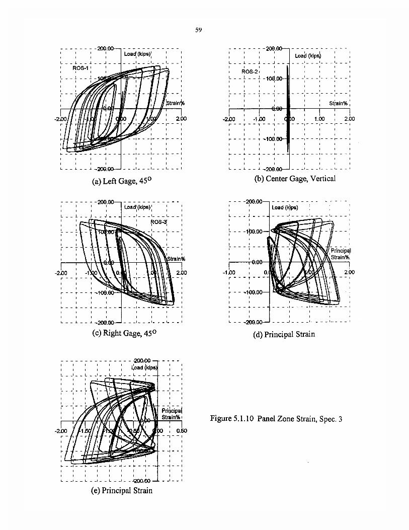

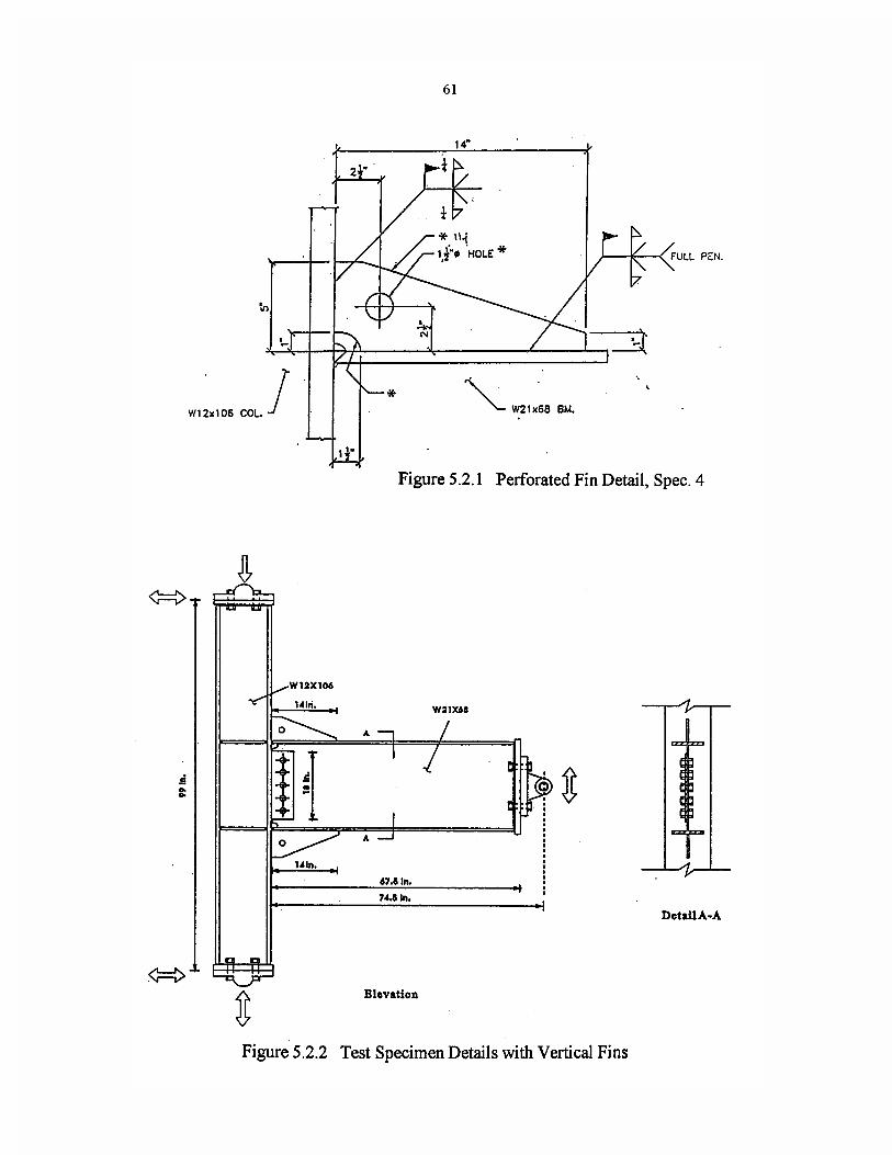


64
A distorted view of the connection is shown in Figure 5.2.5. This clearly indicates the effect
of the doubler plate in restricting deformations of the panel zone and forcing most of the deforma-
tion into the beam.
The specimen was subjected to 15 cycles of load and reached a total rotation of more than 4%.
The test was stopped at this point due to severe deformation in the beam and the concern for dam-
aging the testing equipment. At this point, the top and bottom beam flanges had developed buck-
les of 1 3/4 inches at the bottom and 2 inches at the top (Figure 5.2.6) and the beam web had
buckled out of plane. There was only a small crack in the weld at the toe of one of the triangular
fins which was due to the prying action of the buckled beam flange. The plastic hinge developed
17 inches from the face of the column at the location of the buckling. By moving the hinge away
from the column face, the problems with the web copes which have led to failures in previous
specimens were eliminated.
The cyclic performance is summarized in Figure 5.2.7. The total rotation, shown in Figure
5.2.7a, reaches a maximum value of 4.2% of which 2.5% is plastic rotation as shown in Figure
5.2.7b. The connection was able to sustain 15 cycles of increasing displacement, reaching a maxi-
mum amplitude of 2.75 inches as shown in Figure 5.2.7c. The load history, shown in Figure
5.2.7d, indicates that the specimen began to unload during the last two cycles due to the buckling
of the flanges and web of the beam after developing a maximum force of 150 kips. The displace-
ment of 2.75 inches and the force of 150 kips compare well with the finite element results.
The connection rotation components are shown in Figure 5.2.8. This figure indicates that the
column rotation was 0.8%, the panel zone rotation was 0.1% and the beam rotation was 3.5% for
a total of 4.4%. Measured strains in the top flange of the beam are shown in Figure 5.2.9. The
strain to the left of the fin near the column face, shown in Figure 5.2.9a, reaches a maximum of
0.7%. Just in front of the fin and to the left, the strain reaches 1.3% (Figure 5.2.9b). Strains mea-
sured on the bottom flange of the beam are shown in Figure 5.2.10. Directly in front of the fin, the
strain is approximately 2%, however, on the final two cycles, the strain increases to more than 5%
(Figure 5.2.10a). Recorded strains to the left, in front of the fin are just slightly less as shown in
Figure 5.2.10b. Strains in the panel zone, shown in Figure 5.2.11, reach a maximum of 0.5%
which indicates yielding and compares well with the finite element results. The fin increases the
moment capacity of the connection by approximately 20%.
5.3 Perforated Fin, Specimen #6
This specimen was similar to specimen #4 except there was no doubler plate in the column.
Instrumentation was the same as the previous two specimens.


72
The load-displacement envelope obtained from a static finite element analysis is shown in
Figure 5.3.1. This curve shows a force of only 127 kips at the beam tip displacement of 3 inches,
indicating the reduced stiffness when the doubler is removed. A color plot of the Von Mises stress
contours, shown in Figure 5.3.2, shows a plastic hinge beginning to form at the end of the fins,
however, the stresses are much lower than in the previous case. A high stress region occurs in
the unstiffened panel zone region indicating yielding and the stresses in the column are consider-
ably higher than previously. A distorted view of the connection is shown in Figure 5.3.3. This
clearly indicates the distortion in the panel zone when the doubler is omitted. Note that almost no
deformation is occurring in the beam.
The specimen was able to sustain 16 cycles in increasing displacement. On the final half cycle
at a displacement amplitude of 3.5 inches (total rotation of 5.2%) the specimen failed suddenly at
the bottom beam flange. The weld holding the fin to the column flange cracked, the bottom flange
of the beam pulled out of the column flange (Figure 5.3.4) and a crack penetrated the column
flange and propagated vertically into the column web in the panel zone (Figure 5.3.5). The exact
sequence of occurrence of these events is not clear. However, at this large rotation, the panel zone
was severely deformed causing a "kink" at the bottom beam flange, not unlike that shown in Fig-
ure 5.3.3. In addition, on the upward half cycle, the column flange and the beam flange are both
loaded in tension. The plastic distortion in the hole of the bottom fin is shown in Figure 5.3.4.
The cyclic performance is summarized in Figure 5.3.6. The specimen was able to develop a
total rotation of more than 4.5% (Figure 5.3.6a) with a plastic rotation of more than 2.5% (Fig-
ure 5.3.6b). It sustained 16 cycles of increasing displacement (Figure 5.3.6c) with a maximum
amplitude of 3.75 inches. After reaching a peak load of 145 kips, there was no unloading until the
last cycle (Figure 5.3.6d).
The components of the connection rotation are summarized in Figure 5.3.7. The figure indi-
cates that the column rotation was more than 1%, the panel zone rotation was approximately .6%
and the beam rotation was 3% for a total of 4.6%.
The cracking in the column flange looked very similar to that observed in a previous study
[12]. This test appears to indicate that if the panel zone is too flexible, the deformation at high
joint rotation may lead to the cracking of the column flange and that this crack may propagate into
the panel zone.
Strains measured on the bottom flange of the beam are shown in Figure 5.3.8. The strains at the toe
of the fin, shown in Figure 5.3.8a, reach a maximum value of 1.75% and a similar value is recorded
toward the edge of the flange (Figure 5.3.8b). Strains measured on the top flange of the beam are


79
shown in Figure 5.3.9. The strains in front of the fin are 1.4% toward the left edge
(Figure 5.3.9c) and reach a maximum at the center of 2.3% (Figure 5.3.9d). Strains in the panel zone,
shown in Figure 5.3.10, reach a maximum of 0.6%, indicating yielding in this region as might be
expected from both the finite element analysis and the observed behavior.


83
6.0 HORIZONTAL FLANGE PLATES
6.1 Dual Plates, Specimen #5
This specimen was a W21x68 beam connected to a W12x106 column which had a standard web
doubler plate. Rectangular plates were added to the top and bottom flanges of the beam as shown
in Figure 6.1.1. However, the configuration and welding are different from those tested by others
[13]. The basic configuration and welding was suggested by Blodgett [14]. The flange plates were
14 inches in length, 8 1/4 inches wide (equal to the beam flange), 3/4 inch thick, and beveled on
three sides. A full penetration weld was used at the column flange, partial penetration welds were
used for the side welds to the beam flange and a 5/8 inch fillet weld was used across the end. The
connection, prior to testing, is shown in Figure 6.1.2. Welds to the column flange were made
using a form of weld overlay. The original FCAW welds at the top and bottom flanges of the
beam were ground level in order to place the plates flat. The plates were then attached by a full
penetration groove weld on top of the existing weld using SMAW with E7018 electrodes.
The instrumentation used in this series of tests is shown in Figure 6.1.3. Strain gages were
placed on top of the flange plate at the column face and on the beam flange at the end of the flange
plate. The figure indicates that a total of 32 channels of data acquisition were used for this series
of tests.
Nonlinear finite element analyses were conducted in an effort to estimate the behavior of this
specimen prior to testing. The load-displacement envelope obtained from a static push test is
shown in Figure 6.1.4. This figure indicates a force of 149 kips at the beam tip is required to
develop a tip displacement of 3 inches. A color plot of the Von Mises stress contours is shown in
Figure 6.1.5. This figure shows that a plastic hinge is forming at the end of the horizontal flange
plates. It can also be seen that the flange is very effective in reducing the stress at the face of the
column and particularly in the region directly above the web cope. Yielding of the panel zone is
indicated with stresses above 50 ksi.
The summary of the cyclic behavior, shown in Figure 6.1.6, indicates that the specimen was
subjected to 15 displacement cycles (Figure 6.1.6c) and reached a maximum displacement of 3
inches on the last three cycles. Total rotation was more than 4.5% (Figure 6.1.6a) with a plastic
rotation of 3% as shown in Figure 6.1.6b. The history of the load at the beam tip, shown in Fig-
ure 6.1.6d, indicates that the beam is beginning to unload during the last two displacement cycles.
Comparing the results of Figures 6.1.6c and 6.1.6d, it can be seen that at a maximum displace-
ment of 3 inches, the beam tip load is 150 kips which agrees very closely with the finite element
solution. The test was stopped due to severe deformation in the beam and the concern for damag-


90
ing the testing equipment. At this point, a plastic hinge had formed at the end of the flange plate as
shown in Figure 6.1.7. This also agrees with the prediction by the finite element analysis. The top
and bottom beam flanges had developed buckles of 1 1/4 inches at the bottom and 2 1/2 inches at
the top (Figure 6.1.8). The beam web had also buckled out of plane. The welds showed no sign of
any cracking. A plastic hinge was developed 16 inches from the face of the column where the
buckling occurred. The unloading of the specimen during the last two cycles at 3 inch displace-
ment was due to the local buckling of the beam web and flanges. This resulted in a reduction of
32% in the maximum load capacity.
The rotation components are shown in Figure 6.1.9 which indicates that practically all of the
connection rotation is occurring in the beam with only 0.5% in the column and 0.2% in the panel
zone. Strains measured on the bottom flange of the beam are shown in Figure 6.1.10. The strain
measured just in front of the flange plate has a maximum value of 2.5% as shown in Figure
6.1.10a. The gage to the right, near the edge of the flange shows a similar value up to the last
cycle when the strain increases to 6% (Figure 6.1.10b). This large increase is most likely due to
the local buckling of the beam flange. Readings on the flange plate near the column face, shown
in Figures 6.1.10c and 6.1.10d, indicate maximum values between 0.8% at the left and 1.0% at
the center which are less than half the values obtained on the beam flange. Peak strains on the top
flange plate, near the column range between 0.4% and 0.8% as shown in Figure 6.1.11. At the
center of the top flange of the beam, just in front of the flange plate, the maximum strain is close
to 4% during the last displacement cycle (Figure 6.1.12). To the right, near the edge of the beam,
the peak strain is 2%. Strains obtained from the column flange near the bottom flange of the beam
indicate a value of 0.3% as shown in Figure 6.1.13. Strains recorded in the panel zone, shown in
Figure 6.1.14, indicate yielding of the column web with maximum strain reaching 0.7%. This is
consistent with the stress results obtained from the finite element analysis.
6.2 Dual Plates, Specimen #7
This specimen was similar to specimen #5 with the exception that it did not have the doubler plate
in the column web. The load-displacement envelope obtained from the finite element analysis is
shown in Figure 6.2.1. This curve indicates that a force of only 111 kips at the beam tip is required


98
to develop a displacement of 3 inches, indicating the reduced stiffness when the doubler is
removed. At maximum displacement of 4.5 inches, a load of 120 kips is required. A color plot of
the Von Mises stress contours, shown in Figure 6.2.2, shows that yielding is just beginning to
occur at the ends of the flange plate, however, the stresses in the column are much higher than for
Specimen #5. A region of high stress occurs in the unstiffened panel zone indicating yielding.
This indicates that most of the deformation is occurring in the panel zone and not in the beam. A
distorted view of the connection is shown in Figure 6.2.3. This clearly indicates the distortion in
the panel zone when the doubler is omitted with almost no deformation occurring in the beam.
Specimen performance was very good as can be seen from the cyclic behavior shown in Fig-
ure 6.2.4. The specimen was subjected to 23 cycles of increasing displacement (Figure 6.2.4c)
with a peak amplitude of 4.5 inches. The total rotation was almost 7% (Figure 6.2.4a) with a plas-
tic rotation capacity of 4% as shown in (Figure 6.2.4b). The loading history, shown in Figure
6.2.4d indicates no unloading of the specimen due to local buckling. The test was stopped after
one cycle at 4.5 inches of tip displacement to protect the test equipment. At this point there was no
visible cracking and no local buckling although a plastic hinge had just started to form in the
beam at the end of the flange plate (Figure 6.2.5) as predicted by the finite element analysis.
Deformation of the column and panel zone can be seen in Figure 6.2.6. Yielding of the column
flanges near the continuity plates was noted and there was significant yielding in the back flange
of the column opposite the continuity plates. This region was identified as one of higher stresses
in the finite element studies (Figure 6.2.2).
Since there was no column doubler, there was extensive plastic deformation in the panel zone.
Contributions to total rotation, shown in Figure 6.2.7, were divided as follows: 1.3% column
rotation, 1.7% panel zone, 3.9% beam for a total of 6.9%. The effect of the panel zone thickness
can be seen by comparing these results with those of specimen #5.
The strain distribution across the top flange plate near the column face can be seen in Figure
6.2.8. At the center, Figure 6.2.8a, the maximum strain was approximately 1.4%. At the middle
of the flanges, Figures 6.2.8b and 6.2.8c, the strains were recorded as 1.4% and 1.2%. At the
edges of the flange plate, strains of 1.3% were measured on both sides as shown in Figures 6.2.8d
and 6.2.8e. Strains in the top flange of the beam just in front of the flange plate are shown in Fig-
ure 6.2.9. At the center of the beam, Figure 6.2.9a, the maximum strain is 2%, whereas, on either
side of the beam, the strains are 2.5% and 2.1% as shown in Figures 6.2.9b and 6.2.9c.


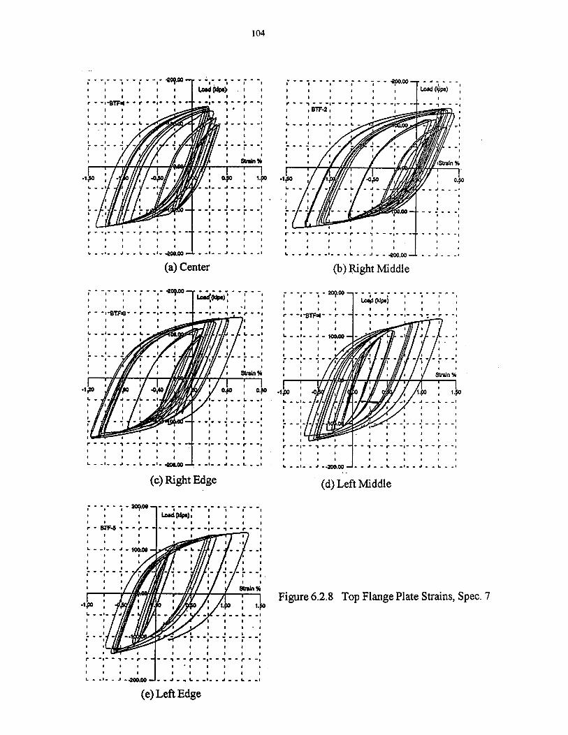


106
This compares well with the finite element solution which indicates that the stresses on the sides
are greater than in the center.
Strains on the bottom flange plates are shown in Figure 6.2.10. At the center, shown in Figure
6.2.10a, the peak strain reaches 1.5%, and similar strains are attained on either side, as shown in
Figures 6.2.10b and 6.2.10c. Measurements taken on the bottom flange of the beam just in front
of the flange plates are shown in Figure 6.2.11. These recordings indicate the strains are almost
uniform across the beam with a peak strain of 3% at the center (Figure 6.2.11a) and almost 3% on
either side (Figures 6.2.11b and 6.2.11c).
Strains measured on the column flange near the bottom flange of the beam are shown in Fig-
ure 6.2.12. Maximum strains at this location are almost uniform with a value of 0.75% at the cen-
ter (Figure 6.2.12a) and 0.8% on either side (Figures 6.2.12b and 6.2.12c). All of these
recordings indicate yield of the column flange. Similar data recorded on the column flange near
the top flange of the beam is shown in Figure 6.2.13. At the center, the maximum recorded strain
is 0.6% as shown in Figure 6.2.13a. On the sides, the recorded values are 0.5% and 0.58% as
shown in Figures 6.2.13b and 6.2.13c. As before, these recordings indicate yielding of the col-
umn flange. Unfortunately, the strain data from the rosette in the panel zone was lost for this test.
6.3 Dual Miniplates, Specimen #8
This specimen which was similar to #5, was retrofitted with what was considered to be a mini-
mum upgrade. The backup bar at the bottom beam flange was removed, the weld was back-
gouged and overlaid with a reinforcing fillet using SMAW with E7018 electrodes. The welds at
the top and bottom flanges of the beam were ground flush with the beam flange and a 4" x 7" x 3/
4" "miniplate" was added to both flanges using SMAW with E7018 electrodes. The miniplate was
connected to the column flange with a full penetration weld over the existing weld and was
welded along both sides with a partial penetration groove weld. The weld at the end of the plate
was a 5/8 inch fillet weld.
The load-displacement envelope obtained from the finite element analysis is shown in Figure
6.3.1. This curve indicates that a force of 131 kips at the beam tip is required to develop a dis-
placement of 3 inches. At maximum displacement of 4.0 inches, a load of 137 kips is required. A
color plot of the Von Mises stress contours, shown in Figure 6.3.2, indicates regions of high stress
at the ends of the miniplate and the formation of a plastic hinge. Note that the yield region has
been moved away from the welded connection to the column flange.


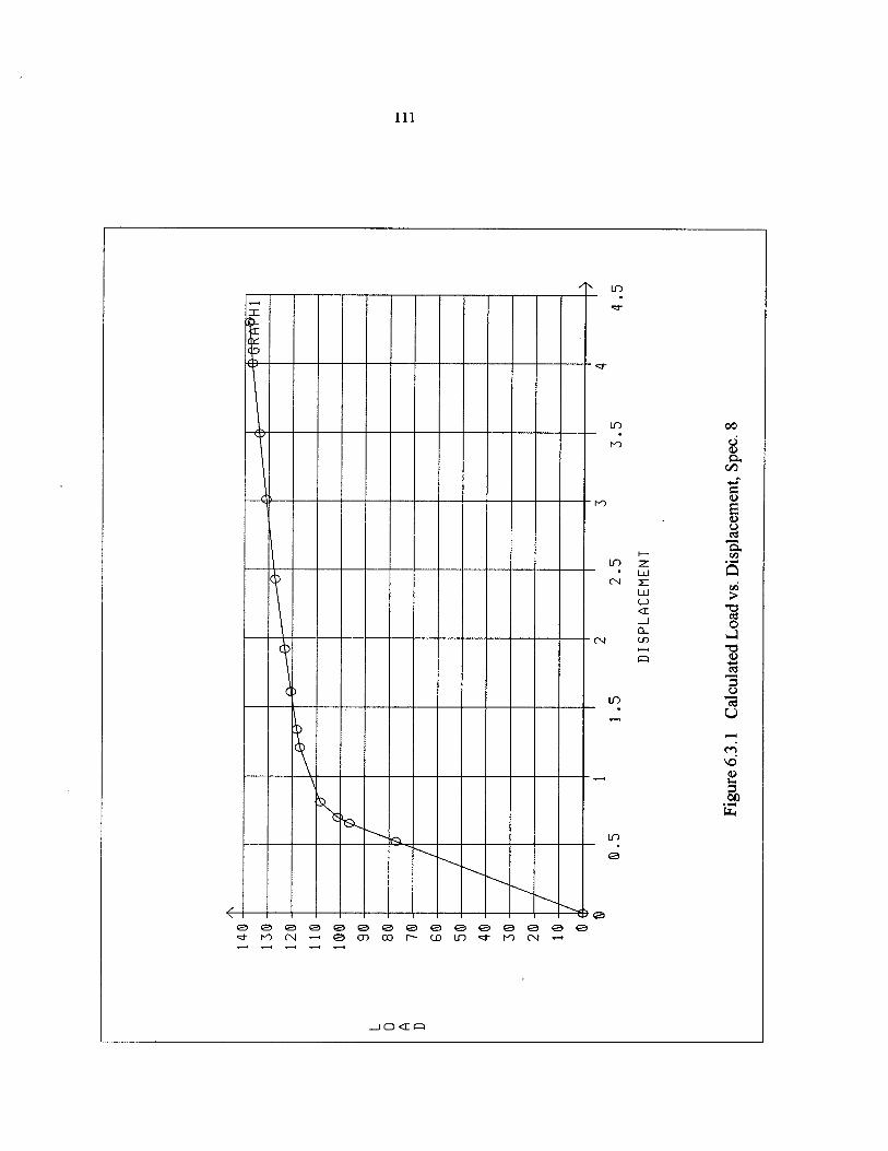


113
The welded miniplate on the bottom flange of the beam is shown in Figure 6.3.3. As can be
seen in Figure 6.3.4, the cyclic performance of the modified connection was very good. The spec-
imen was able to sustain 19 cycles of increasing displacement (Figure 6.3.4c) and reached a total
rotation of 6% (Figure 6.3.4a). A plastic rotation capacity of 4% (Figure 6.3.4b) was achieved
although the specimen began to unload on the last three cycles as shown in Figure 6.3.4d. This
occurred due to severe local buckling of the beam flanges and web, shown in Figure 6.3.5, and
caused the test to be stopped after two cycles at 4.0 inches of tip displacement (6% total rotation).
There was approximately a 32% reduction in maximum load due to this unloading. At this point
there was no visible cracking on the test specimen, particularly the welds. However, it appeared
the plastic hinge zone had just reached the column face, therefore, it does not seem advisable to
reduce the length of the flange plates any further.
The summary of the rotation components, shown in Figure 6.3.6 indicates that practically all
of the rotation occurred in the beam. Strains recorded on the top beam flange in front of the flange
plate are shown in Figure 6.3.7. Strain at the middle of the beam flange on either side of the web
(Figures 6.3.7a and 6.3.7b) indicate peak strains of almost 4%. Near the edge of the flange, the
peak strain is 3% as shown in Figure 6.3.7c. Strains in the beam flange and miniplate near the
face of the column are shown in Figure 6.3.8. The measured strain on the miniplate at the center-
line of the beam flange reaches a maximum value of 1.2% (Figure 6.3.8a). Near the edges of the
miniplate (Figures 6.3.8b and 6.3.8c) the strains on both sides are 1.5%. The strains near the
edge of the beam flange, shown in Figures 6.3.8d and 6.3.8e, reach 1.5% on one side and 0.9%
on the other.
Strains measured on the bottom flange of the beam just in front of the miniplate are shown in
Figure 6.3.9. The data shown in Figures 6.3.9a and 6.3.9b are for the two gages located midway
between the web and the edge and both indicate strains of approximately 5%. Strains measured on
the miniplate at the bottom flange of the beam near the column face are shown in Figure 6.3.10.
Just above the beam web, the peak recorded strain on the miniplate is 1.2% as shown in Figure
6.3.10a. On either side, near the edge of the miniplate, the strains increase to 1.5% and 1.25%
(Figures 6.3.10b and 6.3.10c). Strain data from the rosette located in the panel zone of the col-
umn is shown in Figure 6.3.11. This data indicates that the behavior of the panel zone during this
test was primarily elastic.
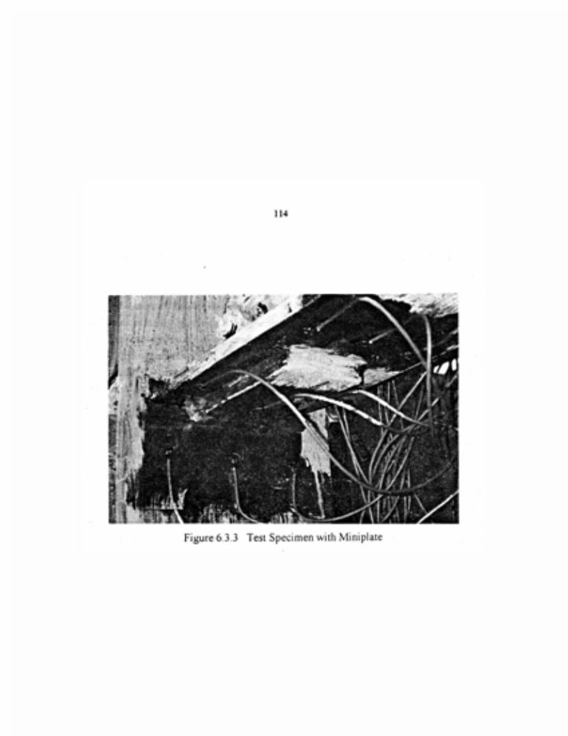


123
6.4 Single Plate, Specimen #9
This specimen was a W21x68 beam connected to a W12x106 column with a doubler plate on one
side of the web. It was retrofitted using a procedure that was used extensively in the field for
repair immediately after the earthquake. In most cases weld cracks were identified at the bottom
flange of the beam and therefore a rectangular flange plate was welded to the beam at this loca-
tion. In this study, a rectangular plate was attached using partial penetration welds along the sides,
a full penetration weld to the column flange and a 5/8" fillet weld along the end of the plate using
SMAW with E7018 electrodes. Nothing was done to the FCAW weld at the top beam flange.
The load-displacement envelope obtained from the finite element analysis is shown in Figure
6.4.1. This curve indicates that a force of 135 kips at the beam tip is required to develop a dis-
placement of 3 inches. A color plot of the Von Mises stress contours is shown in Figure 6.4.2. In
the computer model, the single flange plate is on the top flange. Yielding is beginning to occur at
the ends of the flange plate, however, it can be seen that there is a significant yield region at the
bottom flange of the beam where there is no flange plate. Limited yielding is indicated in the
panel zone.
The test specimen with the single flange plate is shown in Figure 6.4.3. Cyclic performance,
shown in Figure 6.4.4, was both predictable and not outstanding. The total rotation, shown in Fig-
ure 6.4.4a was 3.8% with a plastic rotation of only 1.7% (Figure 6.4.4b). The top flange of the
beam, without the plate, was the first to show indications of yielding with yielding at the bottom
flange occurring only near the end of the test. The specimen was able to sustain 14 displacement
cycles as shown in Figure 6.4.4c. Unloading of the specimen occurred on the last displacement
cycle resulting in a 24% drop in loading capacity (Figure 6.4.4d). During the 13th cycle at a dis-
placement of 2.7 inches, inelastic buckling of the top beam flange led to the formation of a slit or
tear (ductile crack) which started at the top web cope hole and extended across the top beam
flange (Figure 6.4.5). At a displacement of 2 inches, the finite element analysis indicates a load of
129 kips at the beam tip. The test results show a load of 130 kips (Figure 6.4.4d)
Rotation components, shown in Figure 6.4.6, indicate that approximately 0.2% rotation
occurred in the column, 0.5% occurred in the panel zone and 3.1% occurred in the beam. Strains
measured on the top flange of the beam, midway between the web and the edge are shown in Fig-
ure 6.4.7. On one side the maximum strain is 4.5% and on the other the maximum strain reaches
5.3%. Maximum strains measured across the flange plate at the bottom flange of the beam were
approximately uniform and varied between 2 and 2.5% as shown in Figure 6.4.8. Strains mea-
sured on the column flange, just below the flange plate on the beam are shown in Figure 6.4.9.
The peak strains are approximately uniform at a value of 0.43% which is above yield. Inelastic


132
behavior of the column flange is indicated by the hysteresis loops showing strain versus beam tip
load. Strains measured on the rosette in the panel zone of the column are shown in Figure 6.4.10.
Inelastic behavior is indicated by strains reaching 1%.
It was hoped that the bottom plate alone might be sufficient to move the plastic hinge away
from the joint. This type of behavior had been observed in an earlier test [12]. However, it did not
work for this specimen. Based on the result of this test, it does not appear that the addition of a
single flange plate on the bottom flange can counted on to reliably produce a significant improve-
ment in connection behavior.


135
7.0 WELD OVERLAY
7.1 Baseline Test, Specimen #12
This test specimen had a W16x77 column without a web doubler plate and a W21x68 beam. The
initial specimen was tested in the "as received" condition with a pre-Northridge welded connec-
tion (FCAW).
The load-displacement envelope obtained from the finite element analysis is shown in Figure
7.1.1. This curve indicates that a force of 103 kips at the beam tip is required to develop a dis-
placement of 3 inches. A color plot of the Von Mises stress contours is shown in Figure 7.1.2.
This figure shows very limited yielding in the beam, however, the panel zone is a region of very
high stress (56 ksi). This indicates that most of the deformation will occur in the panel zone and
not in the beam.
The cyclic performance of the specimen is summarized in Figure 7.1.3. The specimen was
able to sustain 16 cycles of increasing displacement as shown in Figure 7.1.3c. The moment ver-
sus rotation history, shown in Figure 7.1.3a, indicates that the total rotation was just over 3.1%
with plastic rotation of 1.8% as shown in Figure 7.1.3b. The loading history, shown in Figure
7.1.3d, indicates increasing load up to the second cycle at a tip displacement of 2 inches when a
sudden unloading of the specimen occurred. On this cycle at a total rotation of 3 percent, a crack
initiated in the root of the weld at the bottom flange of the beam (Figure 7.1.4) and propagated
diagonally through the column flange and into the panel zone as shown in Figure 7.1.5. This type
of failure pattern is very similar to those observed in a severely damaged steel frame following the
earthquake [12]. At a displacement of 2 inches, the finite element analysis indicates a beam load
of 95 kips which is close to the 92 kips measured in the test prior to unloading of the specimen.
The rotation components in the connection region are shown in Figure 7.1.6. This figure indi-
cates that the column rotation was 1.3% (Figure 7.1.6a), the panel zone rotation was .8% (Figure
7.1.6b) and the beam rotation was 1.0% (Figure 7.1.6c) for a total rotation of 3.1% as shown in
Figure 7.1.6d.
7.2 Class A Repair, Specimen #10
During the initial loading, a second specimen that was identical to #12, also failed at a total rota-
tion of approximately 3 percent. However, the failure mode for this specimen was a vertical crack
through the weld at the bottom flange of the beam. Ultrasonic testing confirmed that the crack
was primarily vertical and that it encompassed a small part of the column flange. Ultrasonic test-
ing of the weld at the top flange of the beam gave no indication of any cracking or defects. This


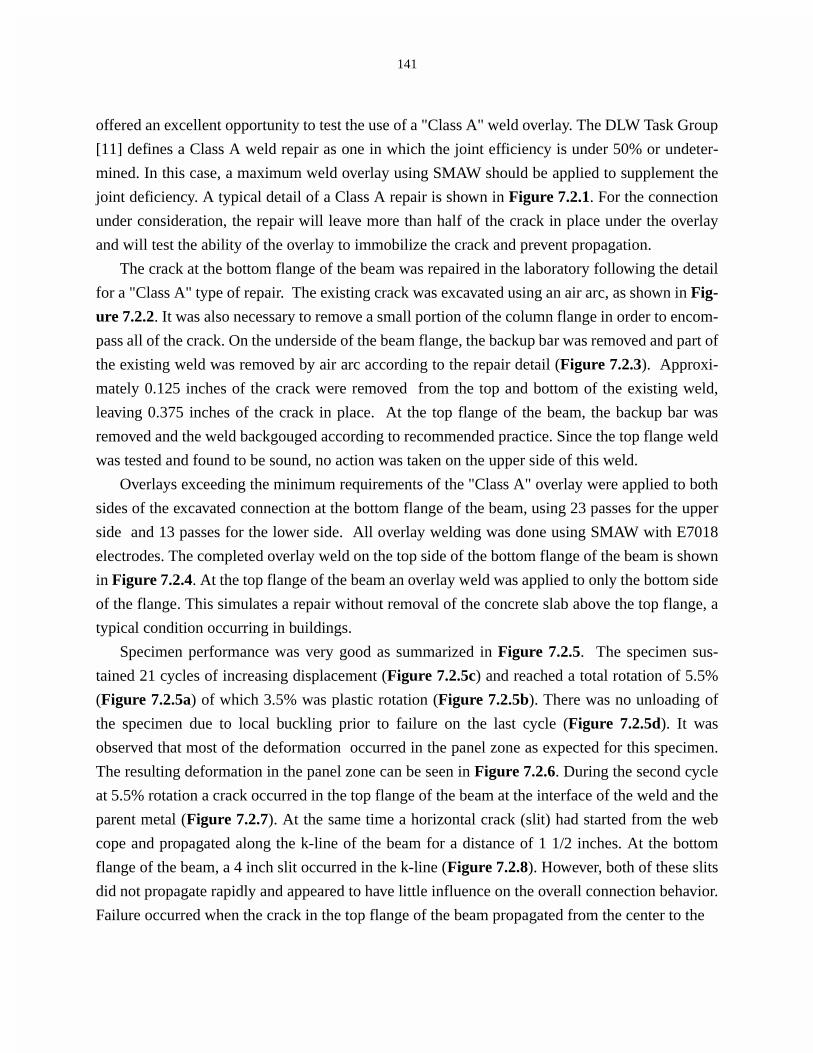
141
offered an excellent opportunity to test the use of a "Class A" weld overlay. The DLW Task Group
[11] defines a Class A weld repair as one in which the joint efficiency is under 50% or undeter-
mined. In this case, a maximum weld overlay using SMAW should be applied to supplement the
joint deficiency. A typical detail of a Class A repair is shown in Figure 7.2.1. For the connection
under consideration, the repair will leave more than half of the crack in place under the overlay
and will test the ability of the overlay to immobilize the crack and prevent propagation.
The crack at the bottom flange of the beam was repaired in the laboratory following the detail
for a "Class A" type of repair. The existing crack was excavated using an air arc, as shown in Fig-
ure 7.2.2. It was also necessary to remove a small portion of the column flange in order to encom-
pass all of the crack. On the underside of the beam flange, the backup bar was removed and part of
the existing weld was removed by air arc according to the repair detail (Figure 7.2.3). Approxi-
mately 0.125 inches of the crack were removed from the top and bottom of the existing weld,
leaving 0.375 inches of the crack in place. At the top flange of the beam, the backup bar was
removed and the weld backgouged according to recommended practice. Since the top flange weld
was tested and found to be sound, no action was taken on the upper side of this weld.
Overlays exceeding the minimum requirements of the "Class A" overlay were applied to both
sides of the excavated connection at the bottom flange of the beam, using 23 passes for the upper
side and 13 passes for the lower side. All overlay welding was done using SMAW with E7018
electrodes. The completed overlay weld on the top side of the bottom flange of the beam is shown
in Figure 7.2.4. At the top flange of the beam an overlay weld was applied to only the bottom side
of the flange. This simulates a repair without removal of the concrete slab above the top flange, a
typical condition occurring in buildings.
Specimen performance was very good as summarized in Figure 7.2.5. The specimen sus-
tained 21 cycles of increasing displacement (Figure 7.2.5c) and reached a total rotation of 5.5%
(Figure 7.2.5a) of which 3.5% was plastic rotation (Figure 7.2.5b). There was no unloading of
the specimen due to local buckling prior to failure on the last cycle (Figure 7.2.5d). It was
observed that most of the deformation occurred in the panel zone as expected for this specimen.
The resulting deformation in the panel zone can be seen in Figure 7.2.6. During the second cycle
at 5.5% rotation a crack occurred in the top flange of the beam at the interface of the weld and the
parent metal (Figure 7.2.7). At the same time a horizontal crack (slit) had started from the web
cope and propagated along the k-line of the beam for a distance of 1 1/2 inches. At the bottom
flange of the beam, a 4 inch slit occurred in the k-line (Figure 7.2.8). However, both of these slits
did not propagate rapidly and appeared to have little influence on the overall connection behavior.
Failure occurred when the crack in the top flange of the beam propagated from the center to the


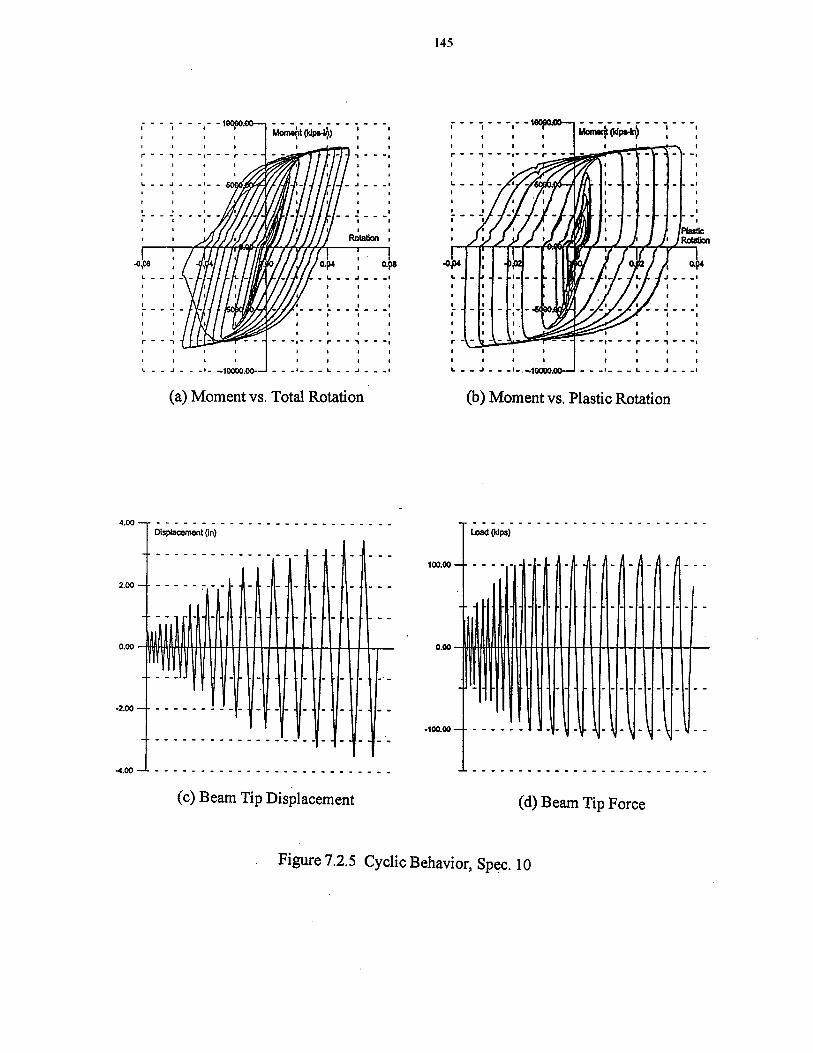


147
sides, as shown in Figure 7.2.9. It should also be emphasized that the overlay appeared to have
completely immobilized the vertical crack at the face of the column.
The rotation components at the connection are shown in Figure 7.2.10. The column rotation,
shown in Figure 7.2.10a is approximately 2.5%. The rotation in the panel zone (Figure 7.2.10b)
has a smooth hysteresis and a maximum value of 2% which is large as expected. The beam rota-
tion (Figure 7.2.10c) is approximately 1.0% for a total rotation of 5.5% (Figure 7.2.10d).
7.3 Baseline Test, Specimen #11
This test specimen used a W16x77 column with a web doubler plate and a W21x68 beam. The
specimen was tested in the "as received" condition with a pre-Northridge welded connection using
FCAW.
The load-displacement envelope obtained from the finite element analysis is shown in Figure
7.3.1. This curve indicates that a force of 119 kips at the beam tip is required to develop a dis-
placement of 3 inches. This compares to a load of 103 kips for Specimen #12 and indicates the
stiffening effect of the doubler plate. A color plot of the Von Mises stress contours is shown in
Figure 7.3.2. This figure shows the formation of a plastic hinge in the beam adjacent to the col-
umn flange. Note the reduced stress in the panel zone which indicates elastic behavior.
The cyclic performance of the specimen is summarized in Figure 7.3.3. The specimen was
able to sustain 19 cycles of increasing displacement as shown in Figure 7.3.3c. The moment ver-
sus rotation curve, shown in Figure 7.3.3a, indicates that the total rotation was just over 3.0%
with plastic rotation of 1.6% as shown in Figure 7.3.3b. The loading history, shown in Figure
7.3.3d, indicates there was no unloading of the specimen until the last cycle when failure occurred
during the first cycle at a displacement of 2.5 inches (4% rotation). On the first down stroke of
this cycle the top flange of the beam suddenly fractured as shown in Figure 7.3.4. The crack
appeared to start in the web cope and propagate outward to the edges of the beam flange. Note
that the finite element analysis indicated a beam tip load of 112 kips at a displacement of 2 inches
compared with 118 kips measured in the test.
The rotation components in the connection region are shown in Figure 7.3.5. This figure
clearly indicates that most of the rotation occurred in the beam. For this specimen, the column
rotation was 0.3%, the panel zone rotation was 0.2% and the beam rotation was 2.6% for a total of
3.1%.
Strains measured on the top flange of the beam are shown in Figure 7.3.6. The peak strain at
the centerline of the beam was measured to be 3% (Figure 7.3.6a) and the same peak strain was
recorded on either side (Figures 7.3.6b and 7.3.6c). At the edges of the beam, the peak strain was


155
2% as shown in Figures 7.3.6d and 7.3.6e. Strains recorded at two locations on the bottom flange
of the beam are shown in Figure 7.3.7. Unfortunately data at the other three locations was lost.
The strain data at this location is similar to that obtained at the top flange. At the location midway
between the centerline and the edge of the flange (Figure 7.3.7a) the peak strain is 3%. At the
edge of the flange the maximum recorded strain is 1.8% as shown in Figure 7.3.7b. Strain data
from the rosette in the panel zone is shown in Figure 7.3.8. This data indicates that the panel zone
remained elastic.
7.4 Specimen #14, Class C Repair
The next specimen was not tested prior to applying the weld overlays and no defects were known
to be present in the existing welds. This specimen represents a field upgrade of a connection made
using FCAW with E70T-4 wire. The overlay procedure is representative of a "Class C" repair. The
DLW Task Group [11] classifies a Class C repair as one in which the dynamic joint efficiency is
over 50%. In this case a minimum overlay using SMAW is applied as shown in the detail in Fig-
ure 7.4.1. Backup bars at the top and bottom beam flanges were removed and the root of the weld
was backgouged per recommended practice. Overlays exceeding the minimum requirements of
the "Class C" overlay were applied to both sides of the top and bottom flanges of the beam. All
overlays were done using SMAW with E7018 electrodes. The completed overlay weld on the
under side of the upper beam flange is shown in Figure 7.4.2 and the overlay weld on the upper
side of the lower beam flange is shown in Figure 7.4.3. Since the overlay weld filled approxi-
mately half of the web cope, the remaining opening was plug welded in an effort to reduce the
possibility of a secondary failure emanating from this region.
Specimen performance again was very good as summarized in Figure 7.4.4. The specimen
was able to sustain 20 cycles of increasing displacement (Figure 7.4.4c). It developed a total rota-
tion of 4.7 percent (Figure 7.4.4a) with a plastic rotation of 3% (Figure 7.4.4b) before starting to
unload as shown in Figure 7.4.4d. At a tip displacement of 2.5 inches (3.9% rotation) small hor-
izontal cracks began to develop in the top and bottom k-line areas of the beam web. At both loca-
tions the plug welds in the web copes cracked away from the beam web. During the first cycle at
a tip displacement of 3 inches (4.7% rotation) significant buckles began to form in the beam
flanges about 4 inches at the top and about 10 inches at the bottom from the face of the column.
This caused the specimen to start to unload as mentioned previously and during the last cycle at a
tip displacement of 3.5 inches (5.5% rotation) the specimen lost approximately 33% of its
moment capacity.


162
During the first cycle at a tip displacement of 3.5 inches (5.5% rotation), a severe buckle
formed in the top flange of the beam about 5 inches from the face of the column. This caused a
separation of the flange and the web which in turn caused the horizontal crack at the top k-line to
extend almost 7 1/2 inches from the edge of the web cope as shown in Figure 7.4.5. At the bottom
flange, the horizontal crack extended approximately 3 1/2 inches from the edge of the web cope
(Figure 7.4.6). On the down stroke, the flexing of the buckled top flange caused a crack to occur
and propagate across the flange as shown in Figure 7.4.7. With the fracture of the top flange, load
was transferred to the web causing yielding around the upper three bolts as can be seen in Figure
7.4.8. Yielding of the top and bottom beam flanges extended a distance of 21 inches from the face
of the column.
The rotation components, shown in Figure 7.4.9, indicate that all of the deformation occurred
in the beam. Strains measured on the bottom flange of the beam, Figure 7.4.10, indicate peak val-
ues of 5%. Strains measured on the top beam flange are shown in Figure 7.4.11. Unfortunately,
both of these gages broke prior to reaching the maximum strain, however, they were able to record
strains of 3% as shown in Figure 7.4.11b.
7.5 Comparative Behavior
The cyclic behavior of specimen #11 which has a web doubler plate is compared with that of
specimen #12 which does not have a doubler plate in Figure 7.5.1. It can be seen that due to
yielding of the panel zone in specimen #12, the moment capacity of the connection is consider-
ably less than the moment capacity of specimen #11 which has the doubler plate. It can be shown
that specimen #12 was only able to develop 90% of the plastic moment capacity of the beam
whereas specimen #11 was able to develop 120%. It can also be seen that the change in stiffness
between the two specimens is relatively small.
The positive effect of a Class A overlay is shown in Figure 7.5.2 by comparing the cyclic
behavior of specimen #10 with that of specimen #12. The overlay repair has increased the total
rotation capacity by 75% (0.031 to 0.054) and has increased the moment capacity by 18% (6833
in-kips to 8083 in-kips).

163
The positive effect of a Class C overlay is shown in Figure 7.5.3 by comparing the cyclic
behavior of specimen #11 with that of specimen #14. This figure indicates that the connection
modification using an overlay was able to increase the total rotation capacity by 18% (0.0393 to
0.0467) and to increase the moment capacity by 6.5% (9000 in-kips to 9583 in-kips).


170
8.0 OTHER REPAIR PROCEDURES
8.1 Perforated Beam Flange, Specimen #13
The specimen was tested with a W16x77 column having a web doubler on one side of the panel
zone so as to force most of the connection deformation into the W21x68 beam. Recent studies
[7,15] have indicated that the use of a reduced beam section (RBS) has shown considerable prom-
ise for new construction. In this case, a section of the beam flange is removed by flame cutting
following a tapered profile which approximates the moment gradient in the beam flange (Figure
8.1.1). It has been suggested by Yang and Popov [15] that drilling holes in the beam flange (per-
forated beam section) might serve the same purpose. The attraction of using the perforated beam
section (PBS) in place of the flame cut RBS is for application of the procedure to the retrofit of
existing buildings. Eliminating the need for fire protection would significantly reduce the cost of
the retrofit procedure.
It is well recognized that the reduction of the beam flange makes the beam section more sus-
ceptible to lateral buckling. In the case of the PBS, this condition was found to be improved by
placing the holes as near to the edge of the flange as possible [15]. The PBS was formed by drill-
ing eight holes with increasing diameters (2@1"ø, 2@1 1/4"ø , 2@1 1/2"ø and 2@1 3/4"ø ) hav-
ing a one inch edge to edge clearance between holes and a 1/4 inch clearance on the edge of the
flange. The smaller hole is located nearest the column. This results in an 18 inch PBS with the
amount of reduction varying form 22% to 39%. Instrumentation for this specimen, shown in Fig-
ure 8.1.2, consisted of 32 channels of data acquisition.
The cyclic behavior of the specimen is summarized in Figure 8.1.3. The specimen was able to
sustain 20 cycles of increasing displacement as shown in Figure 8.1.3c. The plot of moment ver-
sus total rotation, shown in Figure 8.1.3a, indicates that the specimen was able to develop a total
rotation of 4 percent with a plastic rotation of 2.5% as shown in Figure 8.1.3b. The loading his-
tory shown in Figure 8.1.3d indicates there was no unloading of the specimen prior to failure.
Failure occurred on the second cycle at a displacement of 2 1/2 inches (4% rotation) by the for-
mation of a crack in the weld at the top flange of the beam (Figure 8.1.4). The crack appeared to
start in the web cope and then propagate outward to the edges (Figure 8.1.5).
The plastic hinge has been shifted from the column face to the center of the hole group as
shown in Figure 8.1.6. The holes in the bottom flange of the beam, some of which are out of
round, are shown in Figure 8.1.7. This figure indicates that the holes have worked as planned and
that there has been no tearing either between holes of between the hole and the edge of the flange.
A yield band has developed between the hole pattern and the web of the beam.


176
Strains measured on the top flange of the beam in front of the hole pattern are shown in Fig-
ure 8.1.8. The strains at the centerline of the beam flange, shown in Figure 8.1.8a, indicate lim-
ited yielding of the flange has occurred. The results from the other two gages, located in line with
the hole patterns on either side of the web, indicate predominately elastic behavior (Figures
8.1.8b and 8.1.8c). Moving closer toward the column, strains recorded by two gages located on
the beam flange between the web and the larger diameter holes are shown in Figure 8.1.9. Both of
these gages indicate strains of approximately 1% with clearly defined yielding. The results
obtained from the next row of gages which are on the beam flange between the web and the
smaller diameter holes are shown in Figure 8.1.10. These gages indicate slightly larger strains of
1.25% at both locations.
The rotation components, shown in Figure 8.1.11, indicate that all of the rotation has occurred
in the beam with negligible amounts in the column and the panel zone. The 2 1/2% plastic rotation
is a definite improvement over the 1.5% plastic rotation obtained by a similar section without PBS
(see Figure 8.1.1b). However, this rotation capacity is less than current design requirements of 3
percent plastic rotation. These results indicate that to meet or exceed this goal, some modification
will have to be done to the connection of the beam flange to the column flange.
The cyclic performance of specimen #13 is compared to that of the baseline specimen #11 in
Figure 8.1.12. Here it can be clearly seen that the perforated beam flange has little effect on the
connection performance. The rotation capacity is slightly larger and the moment capacity is
slightly less.
8.2 Web Access Windows, Specimen #15
This specimen was tested for Matt Construction Company who have given permission to include
this data in this report. The repair procedures used for this specimen are representative of those
used to repair moment connections requiring a column flange replacement in moment frames
located on the perimeter of a building. Access to the exterior side of the connection was obtained
by cutting windows in the beam web and the column web adjacent to the connection of the bottom
beam flange to the replaced column flange.
A detail of the full size test specimen is shown in Figure 8.2.1. The column is a W30x173
with a height of 11'-0 between connection points. The beam is a W36x135 with a span of 11'-3"
from the face of the column to the load point. The panel zone was reinforced with a 5/8 inch web
doubler which extended 6 inches above the top continuity plate and 6 inches below the bottom
continuity plate. The distance to the actuator from the face of the column was 135 inches and the
distance from the face of the column to the displacement transducer was 122 inches. No axial load


182
was applied to the column other than that transmitted by shear from the beam. All repair welding
was done in the laboratory using SMAW with E7018 electrodes. Material is A36 steel with
assumed Fy = 47 ksi. The specimen in the test frame is shown in Figure 8.2.2. Displacement con-
trolled loading at the beam tip was applied by a 300 kip actuator.
Specimen performance, summarized in Figure 8.2.3, met the test objective of developing a
total rotation of 3.5% as shown in Figure 8.2.3a. The plastic rotation capacity at this displacement
was 2.0% as shown in Figure 8.2.3b. The specimen was able to sustain 17 displacement cycles in
satisfying the test objectives (Figure 8.2.3c). The loading history, shown in Figure 8.2.3d, indi-
cates there was only a slight unloading of the specimen on the up stroke toward the end of the test.
Buckling of the beam web in the vicinity of the window occurred near initial yield. This was fol-
lowed by an unsymmetrical buckling of the beam top flange (Figure 8.2.4) and the beam web.
Plastic hinging occurred in the top beam flange adjacent to the connection to the column face,
however, the hinging in the bottom beam flange was moved away from the column face by the
length of the window plate (12 inches). Due to the unsymmetrical buckling of the top beam flange
and the top of the beam web, loading in the up direction was not continued due to deformation of
the test specimen. However, additional displacement cycles were applied in the down direction as
shown in the loading history. The specimen was able to reach a total rotation of 5% in this direc-
tion without failure of any of the repair welds.
The rotation components of connection rotation are summarized in Figure 8.2.5. These results
indicate that the rotation of the column is 0.9%, the panel zone rotation is almost zero and the
beam rotation is 2.7% for a total rotation of 3.6%.
Strain components obtained from a rosette at the center of the column web in the panel zone
are shown in Figure 8.2.6. These results indicate that the behavior is predominately linear elastic.
The results indicate that there may be some inelastic behavior due to the welding that has been in
the vicinity of the windows. A second rosette was located at the center of the panel zone on the
web doubler plate. The strains obtained from this gage, shown in Figure 8.2.7, indicate that the
behavior is linear elastic with all strains less than 0.1 percent.
A third rosette was located at the center of the window in the column web. Results obtained
from this gage are shown in Figure 8.2.8. Here the behavior is clearly linear elastic with all strains
less than 0.05 percent. A rosette was also located at the center of the window in the lower part of
the beam web, adjacent to the column. Strains recorded by this gage is shown in Figure 8.2.9.
This gage indicates significant inelastic deformation which might be expected in this region adja-
cent to the column flange. Maximum strains reach 0.6% as shown in Figure 8.2.9d.
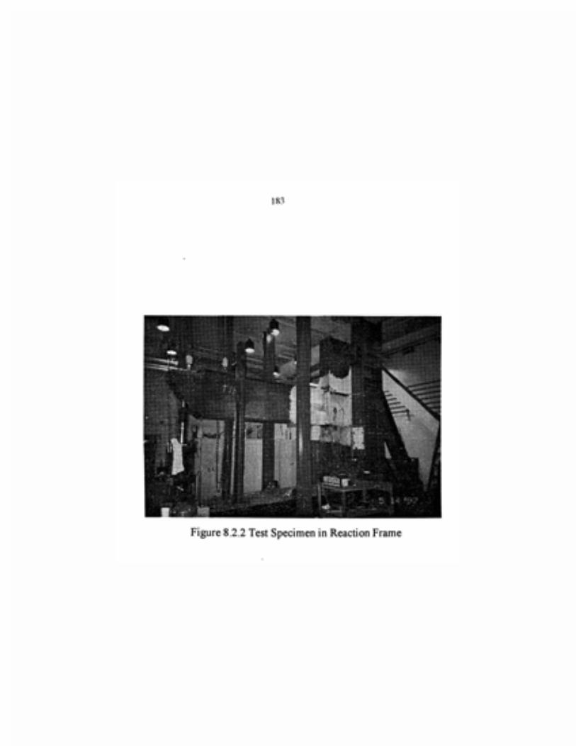


189
Strains recorded across the bottom flange of the beam adjacent to the column flange are
shown in Figure 8.2.10. Maximum strains occur at the center of the beam flange and on the right
edge and reach values of just over 1.0 percent (Figures 8.2.10a and 8.2.10d). Maximum strains
on the opposite side only reach 0.4 percent (Figure 8.2.10b) and 0.6 percent midway between
center and edge (8.2.10c). These results indicate the nonsymmetrical behavior due to the addition
of the cover plates on the web windows.
Strains recorded in the corner of the panel zone in the vicinity of the web windows are shown
in Figure 8.2.11. In general the behavior is linear elastic with recorded strains less than 0.1 per-
cent. The gage shown in Figure 8.2.11a, indicates some inelastic behavior. This gage is located
on the column web between the two windows and adjacent to the column flange replacement
plate. Due to the significant amount of welding done in this region as part of the repair process,
there may be considerable residual stresses which result in the yielding at the lower recorded
strains.
Strains recorded on the back column flange are shown in Figure 8.2.12. Both of these, one
above the beam flange and the other below the beam flange, are linear elastic with strains less than
0.1 percent. Strains recorded in the column web, just above the continuity plate are shown in Fig-
ure 8.2.13. This data indicates limited inelastic behavior with strains just reaching 0.2 percent.
The results of this test indicate that the performance of this type of repair can be improved by
delaying or preventing the buckling of the beam web which appeared to be influenced by the win-
dow in the beam web and the nonsymmetry of the closure plate. Addition of a vertical stiffener at
this location may further improve performance.
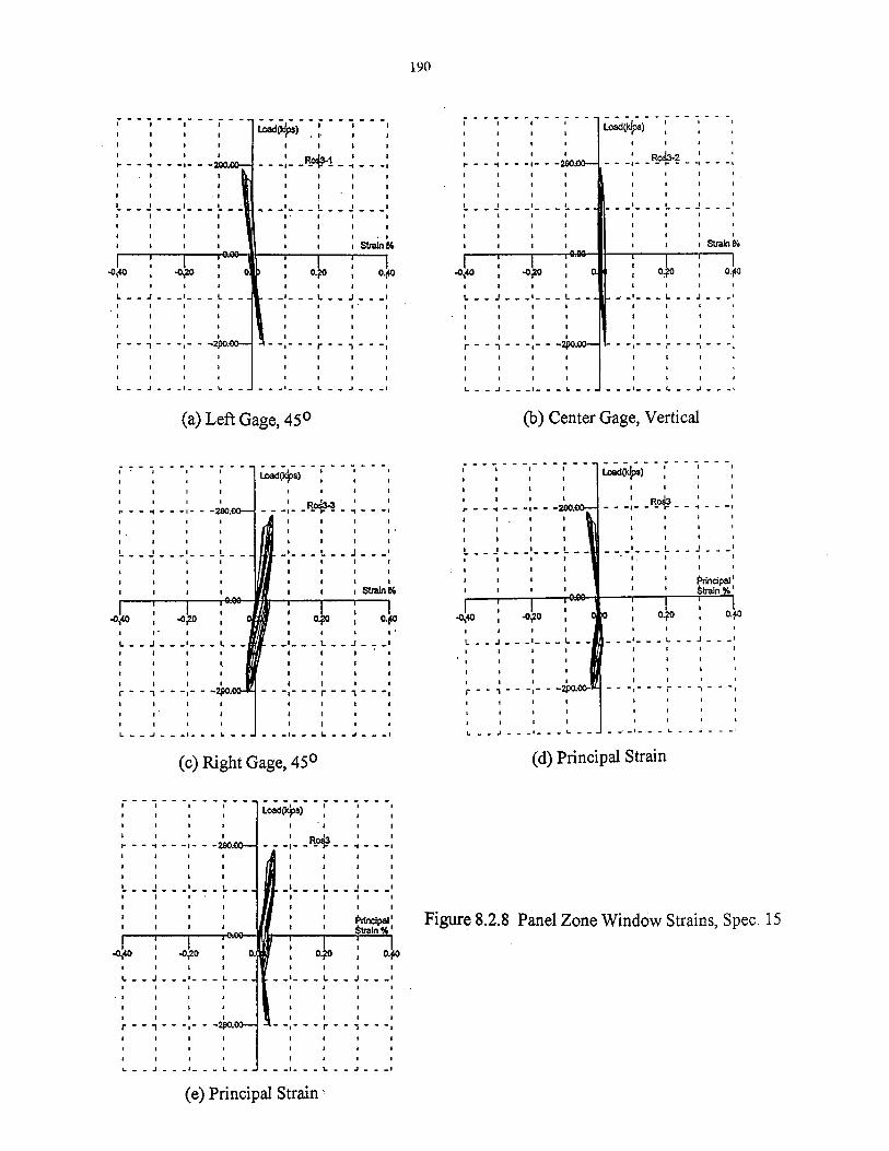


195
9.0 SUMMARY AND CONCLUSIONS
Analytical and experimental studies were conducted on large scale test specimens representing
four general repair/retrofit procedures. These included weld replacement, horizontal flange plates,
vertical flange plates and weld overlays. One test was conducted on a specimen having a perfo-
rated beam flange detail which does not require welding and a final test was conducted on a full
scale repair specimen containing web windows in the beam and panel zone.
Important parameters for qualifying the performance of welded moment connections are the
maximum rotation capacity, maximum plastic rotation capacity, ratio of maximum moment
capacity to plastic moment capacity based on measured yield strength of the material and dis-
placement ductility capacity defined as the ratio of the maximum rotation to the rotation at yield.
These parameters are shown in the form of bar charts in Figure 9.0.1. The total rotation and the
plastic rotation are shown in Figure 9.0.1a and the moment ratio and ductility ratio are shown in
Figure 9.0.1b. The SAC Joint Venture (2) has recommended a plastic rotation capacity of 0.03
radians (3%) as a guideline for rotation capacity although a lessor value can be used if it can be
demonstrated that it will not be exceeded by the earthquake demand.
The initial two specimens (#1 & #2) were tested in the "as received" condition. Both of these
failed by a pull-out of the bottom beam flange and were only able to develop plastic rotations of
0.62% and 1.5%, well below the SAC criteria. Moment ratios were close to unity and the ductility
ratio varied between 1.2 and 2.2. The two specimens were repaired using what is defined as a
Class B weld repair procedure. This procedure requires gouging out the existing weld along with
any crack extension into the column flange and rewelding using SMAW with an E7018 electrode.
On testing following repair, the first specimen (#1B) developed a plastic rotation of 2.0% and the
second specimen (#2B) developed 2.1%. Ductility capacities were also increased to 1.9 and 2.3
respectively. Both Class B repairs improved the connection performance, however, the improve-
ment was not enough to meet the specified criteria of 3% plastic rotation.
The next three specimens shown in the Figure 9.1, #10, #11, and #12, have a W16x77 column
section and were tested in the "as received" condition. Specimen #10 developed a plastic rotation
of 2.3% due to large panel zone deformations, however, the moment capacity was less than the
plastic moment. Specimens #11 and #12 were only able to develop plastic rotations on the order
of 1.7% with specimen #12 having a moment capacity less than the full plastic value.
Specimen #10 was repaired using a Class A weld overlay with SMAW and E7018 electrodes
and became specimen #10A. A 3/8 inch vertical crack at the column face was left in place and
covered by the overlay weld. It can be seen that this specimen was able to develop a plastic rota-


197
tion of 3.5% on retesting and the moment capacity was increased above unity. The overlay was
successful in immobilizing the crack that was left in the existing weld. Specimen #14 was not
tested prior to applying a weld overlay, therefore, this specimen represented a weld modification.
After a minimum, Class C overlay was applied, this specimen became #14C. With the overlay, the
specimen was able to develop a plastic rotation of 3%, the moment ratio increased to 1.25 and the
ductility capacity increased to 2.5. Both of the specimens repaired or modified using weld over-
lays were able to meet the performance criteria of 3% plastic rotation.
Specimens #5, #7, and #8 have W12x106 columns and are modified using rectangular cover
plates on the top and bottom flanges. Specimen #8 uses a mini-plate which is a half sized plate. It
can be seen in Figure 9.1a that these three specimens performed very well developing plastic rota-
tion capacities of 3%, 4.3% and 4.1% respectively. With the addition of the cover plates on the
flanges, the moment capacity is increased and the moment ratios, shown in Figure 9.1b were 1.5,
1.4, and 1.4 respectively. Ductility ratios ranged between 2 and 3.1. All three specimens modified
by adding cover plates to the top and bottom beam flanges either met or exceeded the 3% plastic
rotation criteria.
Specimen #9 was modified by the addition of a rectangular plate to the bottom flange of the
beam, a repair technique widely used following the earthquake. The behavior of this specimen
was disappointing since it was only able to develop a plastic rotation of 1.5% before failing by a
fracture at the top flange of the beam, however, the moment ratio was 1.5 and the ductility was
almost 2.5. In a previous test (12), this type of repair resulted in much better performance, result-
ing in a plastic rotation capacity of more than 3%. Part of the reason for this improved behavior
may be due to welding of the shear tab in the earlier test.
A vertical plate (fin) was added to the top and bottom flanges of specimens #3, #4 and #6 and
resulted in a reasonable improvement in performance with plastic rotation capacities in the range
of 2.5% to 3.0%. Moment ratios were between 1.4 and 1.5 and the ductility ratio varied between
1.9 and 2.5.
The final specimen shown in Figure 9.1 is #13. This specimen was modified by drilling holes
in the beam flanges to have the shape of a tapered RBS ("dog bone"). The performance of this
specimen was good but not outstanding. It developed a plastic rotation of 2.5% prior to a failure of
the weld at the top flange. It was able to develop the full plastic moment capacity of the section
prior to failure and had a ductility ratio of 2.4. Recall that the intent of this test was to improve the
performance of an existing connection without requiring any welding.
The results of these repairs/modifications can be summarized as follows:

198
(a) The use of a Class B weld repair resulted in a small improvement in performance relative
to the initial behavior for the two specimens tested, repaired and retested. However, this
performance did not come close to meeting the SAC criteria.
(b) Both specimens which were repaired with weld overlays according to the details given for
either Class A or Class C repair, exceeded current requirements for cyclic performance
(plastic rotations of 3.5% and 3.2% were attained). The Class A procedure was also shown
to effective for stopping an embedded, vertical crack in the existing weld.
(c) The cost estimates for applying overlay welds to this size of steel specimen are either equal
to or less than those associated with other repair procedures. This procedure should be par-
ticularly applicable to the repair of welded connections with only minor weld cracking or
indications of weld cracking or to the modification of connections in existing buildings
having welded connections made using FCAW with E70T-4 wire.
(d) The overlay weld is designed to carry the entire load, thereby allowing the existing weld to
provide added redundancy and to accommodate secondary stresses.
(e) If the overlay weld is extended beyond the web cope, it appears to have a beneficial effect
by preventing cracks from propagating through the beam flange. Instead, horizontal cracks
(slits) which emanate from the web cope run along the k-line of the beam. These cracks
appear to have a limited effect on connection performance until the later stages of the
loading when local buckling of the beam flange may occur.
(f) It appears that the use of a proper overlay weld with adequate toughness and ductility can
successfully stop the propagation of existing weld cracks and defects.
(g) Repair or upgrade using weld overlays will have minimal effect on the overall dynamic
response of the building since changes to member lengths and stiffness are minimal.
(h) The use of the horizontal flange cover plates and the associated welding procedure proved
to be very successful in modifying both the strength and rotation capacity of the connec-
tion with plastic rotations in excess of 3 percent being obtained for all three specimens.
The use of partial penetration welds along the sides of the cover plate securely connected
the plate to the beam flange and no cracks or tears were found following any of the tests.
(i) The use of a half-size (mini) cover plate resulted in high rotation capacity with the plastic
rotation reaching 4.1 percent when the test was stopped. The use of the miniplate also
reduces the cost of the plate material, reduces the cost of the partial penetration welding
and improves the accessibility for making the required welds.

199
(j) The use of a flange plate on one flange is only marginally successful due to the unknown
condition of the weld at the remaining flange. Hence the failure may simply be shifted
from the bottom flange to the top flange. A good estimation of the condition of the unre-
paired flange is essential if this scheme is to be successful. It also appears that welding the
shear tab is beneficial.
(k) The use of a vertical triangular plate (fin) on the top and bottom flanges of the beam
resulted in a successful upgrade. The moment capacity of the connection was increased by
approximately 20 percent and plastic rotation capacities between 2.5 percent and 3.0 per-
cent were obtained for the three specimens. The use of a drilled hole in the fin serves to
move the critical section from the face of the column to the hole and thereby limits the
force that can be transmitted to the welds at the column face. This type of connection
upgrade has been used in at least two low rise steel buildings in the Los Angeles area
[Anderson, 1997]. The fins are shop welded to the beam flanges and then field welded to
the column.
(l) Beam flange reduction using a perforated beam flange in the shape of a tapered RBS (dog-
bone) proved marginally successful. The detail was able to move the plastic hinge away
from the connection to the approximate center of the hole pattern. The hole pattern worked
very well by restraining lateral buckling and flexing without tearing. However since noth-
ing was done to the existing welds in order to avoid the need for welding, their behavior is
a big uncertainty. The tested specimen developed a plastic rotation of 2.5% before a crack
occurred in the weld area at the top beam flange. The overall performance was similar to
that of the baseline specimen.
(m) Both of the columns used in this study, W12x106 and W16x77, are borderline for meeting
the panel zone strength requirement in the Uniform Building Code. If the nominal yield
strength of the A36 steel, Fy = 36 ksi, is used, the panel zone capacity is adequate to
develop the plastic moment capacity of the beam. However, if the actual yield strength of
the A36 steel, Fy = 47 ksi, is used the strength of the panel zone is not sufficient. There-
fore, the columns without doubler plates experienced substantial yielding in the panel
zone.
(n) The effect of the weak panel zone on the connection performance is to reduce the moment
capacity, increase the rotation capacity and reduce the local buckling in the connecting
beam flanges.

200
(o) Access windows in the beam web and in the panel zone are necessary for repairing
moment connections in frames located on the perimeter of a building. The full scale test
specimen was able to meet the test objective of reaching a total rotation of 3.5 percent. At
this rotation, the plastic component was 2.0 percent. The eccentricity in the beam web due
to the window and associated cover plate, appeared to cause premature buckling. This pre-
vented testing to failure due to the out of plane deformation of the beam and concern for
the test fixtures and apparatus.

201
REFERENCES
1. Bertero, V.V., J. C. Anderson, and H. Krawinkler. 1994. Performance of Steel Building Struc-
tures During the Northridge Earthquake. UCB/EERC-94/09 (August). University of Califor-
nia, Berkeley, California: EERC.
2. SAC Joint Venture. 1995. Interim Guidelines: Evaluation, Repair, Modification and Design
of Steel Moment Frames. Report No. SAC-95-02. Sacramento, California.
3. Shuey, B.D., M.D. Englehardt and T.A. Sabol. 1996. Testing of Repair Concepts for Dam-
aged Steel Moment Connections. SAC Report 96-0, Part 2 (March). Sacramento, California:
SAC Joint Venture Partnership.
4. Whittaker, A. S., A. Gilani and V. V. Bertero. 1996. Seismic Testing of Full-Scale Beam-Col-
umn Assemblies. Part 1. SAC Report 96-01 (March). Sacramento, California: SAC Joint Ven-
ture Partnership.
5. Uang, C. M., and C. Bondad. 1996. Static Cyclic Testing of Pre-Northridge and Haunch
Repaired Steel Moment Connections. Report No. SSRP-96/02. San Diego, California: Uni-
versity of California, Division of Structural Engineering.
6. Kaufmann, E. J., M. Xue, Le-Wu Lu, and J. W. Fisher. 1996. “Achieving Ductile Behavior of
Moment Connections.” Modern Steel Construction (January).
7. Yang,T-S and E. P. Popov. 1995. Behavior of Pre-Northridge Moment Resisting Steel Con-
nections. UC/EERC-95/08 (August). Berkeley, California: EERC, University of California.
8. Iwankiw, N. R. and C. J. Carter. 1995. "The Dogbone: A New Idea to Chew On." Modern
Steel Construction (April).
9. Engelhardt, M. D., T. Winneberger, A. J. Zekany, and T. J. Potyraj. 1996. "The Dogbone Con-
nection: Part II." Modern Steel Construction (August).
10. Structural Research and Analysis Corp. (SRAC). COSMOS/M Advanced Modules User
Guide, Part 1, First ed. Version 1.70. Santa Monica, California.
11. Simon, W., J. Anderson, J. Compton, W. Hayes, and P. Maranian. 1997. Dynamic Load Welds
for Repair of Existing Steel Moment Frame Buildings Damaged From Earthquakes. DLW
Task Group. Report No. 1341. Los Angeles: Brandow & Johnston Assoc.
12. Anderson, J. C., R. G. Johnston, and J. E. Partridge. 1995. Post Earthquake Studies of a Dam-
aged Low Rise Office Building. Report No. CE95-07 (December). Los Angeles: University of
Southern California, Department of Civil Engineering.

202
13. Blodgett, O. W. 1994. Letter to Committee on Northridge Earthquake (September). The Lin-
coln Electric Company.
14. Yang, T-S and E. P. Popov. 1995. Experimental and Analytical Studies of Steel Connections
and Energy Dissipater. UCB/EERC-95/13 (December). Berkeley, California: EERC, Univer-
sity of California.
15. Anderson, J. C. 1997. A Welded Moment Connection For Low Rise Steel Frames. The
EERC-CUREe Symposium in Honor of Vitelmo V. Bertero. UCB/EERC-97/05 (February).
Berkeley, California: EERC, University of California.
16. International Conference of Building Officials. 1994. Uniform Building Code. Whittier, Cali-
fornia.