Pacific Earthquake Engineering Research...
108
André Filiatrault Constantin Christopoulos and Christopher Stearns University of California, San Diego Guidelines, Specifications, and Seismic Performance Characterization of Nonstructural Building Components and Equipment Pacific Earthquake Engineering Research Center PEER 2002/05 SEPTEMBER 2001
Transcript of Pacific Earthquake Engineering Research...
André FiliatraultConstantin Christopoulos
and
Christopher Stearns
University of California, San Diego
Guidelines, Specifications, and Seismic PerformanceCharacterization of
Nonstructural Building Components and Equipment
Pacific Earthquake EngineeringResearch Center
PEER 2002/05SEPTEMBER 2001
i
Guidelines, Specifications, and Seismic Performance Characterization of
Nonstructural Building Components and Equipment
André Filiatrault Professor
Department of Structural Engineering University of California, San Diego
Constantin Christopoulos
Graduate Student Researcher
Christopher Stearns Undergraduate Student Researcher
Final Report
PEER Report 2002/05 Pacific Earthquake Engineering Research Center
College of Engineering University of California, Berkeley
September 2001
iii
ABSTRACT
The main objectives of the research project reported herein are to identify gaps in knowledge
regarding the seismic behavior of nonstructural building components and to help develop a
research strategy within the Pacific Earthquake Engineering Research (PEER) on nonstructural
building components.
For this purpose, existing guidelines and regulations for the design and testing (qualification) of
nonstructural components were compared, and published analytical and experimental research
on nonstructural components was reviewed.
Chapter 1 presents an introduction to this project along with a general discussion on the need to
address the seismic behavior of nonstructural building components. In Chapter 2, the
performance of nonstructural building components during the recent February 28, 2001,
Nisqually, Washington, earthquake is reviewed. The performance of nonstructural components
during other earthquakes in the United States is reviewed in Chapter 3. In Chapter 4, an
inventory and comparison of existing regulations and guidelines for the seismic design and
specification of nonstructural building components are presented. Past analytical and
experimental investigations on the seismic response of nonstructural building components are
briefly reviewed in Chapter 5. The computerized database that has been developed in this project
to centralize this large amount of information, as well as to facilitate any future literature
searches on the seismic behavior of nonstructural building components, is briefly described in
Chapter 6. Chapter 7 provides a summary of gaps in knowledge and recommendations for the
development of a rational research plan on nonstructural building components.
iv
ACKNOWLEDGMENTS
This work report was supported in part by the Pacific Earthquake Engineering Research Center
through the Earthquake Engineering Research Centers Program of the National Science
Foundation under award EEC 9701568. The opinions, findings, conclusions, and
recommendations expressed herein are those of the authors and do not necessarily reflect views
of PEER.
We greatly appreciated the input and coordination provided by Dr. Gregory Deierlein, Deputy
Director of PEER and Professor at Stanford University. The collaboration of Professor Eduardo
Miranda of Stanford University, who was conducting a parallel research project on the capacity
of nonstructural building components, is also acknowledged.
Finally, the authors acknowledge the contribution of Dr. Avigdor V. Rutenberg, from the
Technion-Israel Institute of Technology, who conducted thorough reviews of this report and also
provided very useful suggestions.
v
CONTENTS
ABSTRACT.................................................................................................................................. iii ACKNOWLEDGMENTS ........................................................................................................... iv TABLE OF CONTENTS ..............................................................................................................v LIST OF FIGURES ..................................................................................................................... ix 1 INTRODUCTION................................................................................................................1 2 PERFORMANCE OF NONSTRUCTURAL BUILDING COMPONENTS
DURING THE FEBRUARY 28, 2001, NISQUALLY EARTHQUAKE.........................5 2.1 Performance of Ceiling Systems ................................................................................6
2.2 Performance of Interior Wall Finishes .......................................................................8 2.3 Performance of Exterior Wall Finishes ....................................................................10 2.4 Performance of Window Systems ............................................................................12 2.5 Performance of Building Contents ...........................................................................13 2.6 Performance of Gas and Water Systems ..................................................................16 3 PERFORMANCE OF NONSTRUCTURAL BUILDING COMPONENTS
DURING OTHER PAST EARTHQUAKES...................................................................17 3.1 Performance of Building Contents ...........................................................................17 3.2 Performance of Building Service Equipment...........................................................18 3.2.1 Performance of Elevator and Escalator Systems..........................................19 3.2.2 Performance of Mechanical, Electrical, and Appliance Equipment ............19 3.2.3 Performance of Ductwork and Piping Systems............................................21 3.3 Performance of Building Utilization Equipment .....................................................22 3.3.1 Performance of Emergency Power Systems ................................................22 3.3.2 Performance of Hazardous Material Storage Systems.................................22 3.4 Performance of Interior Architectural Elements ......................................................23 3.4.1 Performance of Interior Partitions................................................................23 3.4.2 Performance of Ceiling Systems ..................................................................23 3.4.3 Performance of Lighting Fixtures ................................................................23 3.4.4 Performance of Raised Computer Access Floors.........................................24 3.5 Performance of Exterior Architectural Elements .....................................................24 3.5.1 Performance of Exterior Curtain Walls........................................................24 3.5.2 Performance of Exterior Veneers .................................................................25 3.5.3 Performance of Glass Doors, Windows, and Glazing..................................26 4 INVENTORY AND COMPARISON OF EXISTING REGULATIONS AND
GUIDELINES FOR THE SEISMIC DESIGN AND SPECIFICATION OF NONSTRUCTURAL BUILDING COMPONENTS.......................................................27
4.1 Seismic Performance Requirements for Nonstructural Building Components........27 4.2 Design Force and Drift Requirements......................................................................28 4.2.1 The SEAOC Blue Book (1996)....................................................................28

vi
4.2.2 The Uniform Building Code (1997).............................................................29 4.2.3 The NEHRP Guidelines for Seismic Rehabilitation of Buildings (1997)
and the International Building Code (2000).................................................30 4.2.4 The Tri-Services Manual “Seismic Design Analysis for Buildings”
(WJE 1996)...................................................................................................33 4.3 Design Guidelines for Building Contents ................................................................34 4.4 Design Guidelines for Building Service Equipment ................................................34 4.4.1 Specific Design Guidelines for Elevator and Escalator Systems.................35 4.4.2 Specific Design Guidelines for Mechanical, Electrical, and
Appliance Equipment ...................................................................................37 4.4.3 Specific Design Guidelines for Ductwork and Piping Systems ...................37 4.5 Design Guidelines for Building Service Equipment ................................................40 4.5.1 Specific Design Guidelines for Electrical and Communication Systems ....40 4.5.2 Specific Design Guidelines for Computer Equipment .................................41 4.6 Design Guidelines for Interior Architectural Elements ...........................................42 4.6.1 Design Guidelines for Interior Partitions .....................................................42 4.6.2 Design Guidelines for Ceiling Systems .......................................................42 4.7 Design Guidelines for Exterior Architectural Elements ..........................................43 4.7.1 Design Guidelines for Exterior Veneers ......................................................43 4.7.2 Design Guidelines for Glass Doors, Windows, and Glazing .......................43 5 INVENTORY AND SUMMARY OF PAST ANALYTICAL AND
EXPERIMENTAL RESEARCH ON NONSTRUCTURAL BUILDING COMPONENTS ............................................................................................45
5.1 Past Studies on Design Force Requirements............................................................45 5.2 Past Studies on Building Contents ...........................................................................49 5.3 Past Studies on Building Service Equipment...........................................................50 5.3.1 Past Studies on Elevator Systems.................................................................50 5.3.2 Past Studies on Mechanical, Electrical, and Appliance Equipment.............52 5.3.3 Past Studies on Ductwork and Piping Systems............................................53 5.4 Past Studies on Building Service Equipment...........................................................53 5.4.1 Past Studies on Communication Systems ....................................................53 5.4.2 Past Studies on Computer Equipment ..........................................................54 5.5 Past Studies on Interior Architectural Components .................................................55 5.6 Past Studies on Exterior Construction......................................................................56 5.6.1 Past Studies on Exterior Curtain Walls ........................................................56 5.6.2 Past Studies on Appendages.........................................................................57 5.6.3 Past Studies on Exterior Veneers .................................................................58 5.6.4 Past Studies on Glass Doors, Windows, and Glazing ..................................59 5.7 Past Studies on Global Performance of Nonstructural Elements.............................61 6 COMPUTERIZED DATABASE ......................................................................................63 6.1 Search Engine...........................................................................................................63 6.2 Literature Submission Engine ..................................................................................66
vii
7 SUMMARY OF GAPS IN KNOWLEDGE AND RECOMMENDATIONS FOR
THE DEVELOPMENT OF A RATIONAL RESEARCH PLAN ON NONSTRUCTURAL BUILDING COMPONENTS.......................................................69
7.1 General Recommendations 7.1.1 Development of Efficient Data Collection Methods....................................69 7.1.2 Development of Post-Earthquake Nonstructural Inspection Procedures .....70 7.1.3 Development of Seismic Analysis Methods for
Nonstructural Components...........................................................................71 7.1.4 Development of Experimental Seismic Qualification Procedures for
Nonstructural Components...........................................................................72 7.1.5 Application of Performance-Based Earthquake Engineering to
Nonstructural Components...........................................................................72 7.1.6 Comprehensive Assessment and Design of Nonstructural Elements...........73 7.2 Recommendations for Building Contents ................................................................78 7.3 Recommendations for Building Service Equipment ................................................79 7.3.1 Recommendations for Elevator and Escalator Systems...............................79 7.3.2 Recommendations for Mechanical, Electrical, and Appliance Equipment..80 7.3.3 Recommendations for Ductwork and Piping Systems.................................81 7.4 Recommendations for Building Utilization Equipment...........................................81 7.4.1 Recommendations for Computer Equipment ...............................................81 7.5 Recommendations for Interior Architectural Components ......................................82 7.5.1 Recommendations for Ceiling Systems .......................................................82 7.6 Recommendations for Nonstructural Exterior Construction....................................82 7.6.1 Recommendations for Exterior Veneers ......................................................82 . 7.6.2 Recommendations for Glass Doors, Windows, and Glazing .......................82 REFERENCES.............................................................................................................................85
ix
LIST OF FIGURES
Figure 2.1 Partial Failure of Suspended Ceiling at Sea-Tac Airport (Filiatrault et al. 2001) .............................................................................................6
Figure 2.2 Partial Failure of Metal Suspended Ceiling at Sea-Tac Airport (Filiatrault et al. 2001) .............................................................................................6
Figure 2.3 Failure of Suspended Lighting Fixtures in Starbucks Headquarters, Seattle (Filiatrault et al. 2001) .............................................................................................7
Figure 2.4 Damage Caused by Unanchored Furniture Items and Building Contents in Starbucks Headquarters, Seattle (Filiatrault et al. 2001) .........................................7
Figure 2.5 Cracking of Drywall Finish in Beam-to-Wall Connection at Sea-Tac Airport (Filiatrault et al. 2001) .............................................................................................8
Figure 2.6 Vertical Cracking of Drywall Finish above Door Opening at Kent Regional District Center (Filiatrault et al. 2001) ....................................................................8
Figure 2.7 Spalling of Plaster in Legislative Building, Olympia (Filiatrault et al. 2001).........9
Figure 2.8 Vertical Cracking of Plastered Walls in Supreme Court of Temple of Justice, Olympia (Filiatrault et al. 2001) .................................................................9
Figure 2.9 Cracking of Plastered Walls in Stairwells of Olympian Apartments, Olympia (Filiatrault et al. 2001) ...........................................................................................10
Figure 2.10 Severe Cracking of Masonry Stairwells in Starbucks Headquarters, Seattle (Filiatrault et al. 2001) ...........................................................................................10
Figure 2.11 Diagonal Cracking of Stucco between Window Openings in Three-Story Apartment Building, Olympia (Filiatrault et al. 2001) ..........................................11
Figure 2.12 Damage to Siding Boards on Wood-Frame House, Olympia (Filiatrault et al. 2001) ...........................................................................................11
Figure 2.13 Control Tower Shattered Windows Boarded with Plywood at Sea-Tac Airport...12
Figure 2.14 Replacing Broken Windowpanes in Pioneer Square Area, Seattle (Filiatrault et al. 2001) ...........................................................................................12
Figure 2.15 Failed Bookshelves in Main Library of Temple of Justice Building, Olympia (Filiatrault et al. 2001) ...........................................................................................13
Figure 2.16 Failed Screwed Wood-to-Metal Connection at Top of Leaning Bookshelf in Main Library of Temple of Justice Building, Olympia (Filiatrault et al. 2001) .............................................................................................................13
x
Figure 2.17 Undamaged Movable Compact Bookshelves and Leaning Conventional Bookshelves in Main Library of Temple of Justice Building, Olympia (Filiatrault et al. 2001) ...........................................................................................14
Figure 2.18 Fallen Books from Massive Wooden Shelves in Law Library of Temple of Justice Building, Olympia (Filiatrault et al. 2001)...............................15
Figure 2.19 Overturned Furniture in Guest Rooms on Eighth Floor of Ramada Inn, Olympia (Filiatrault et al. 2001) ............................................................................15
Figure 2.20 Rupture of Supply Water Line to 3000-Liter Storage Tank in Rooftop Mechanical Room of Ramada Inn, Olympia .........................................................16
Figure 6.1 Searching the Database..........................................................................................64
Figure 6.2 Results from Search by Author..............................................................................65
Figure 6.3 Results from Search by Words in Title..................................................................66
Figure 6.4 Article Addition Form ...........................................................................................67
1
1 Introduction
In many strong earthquakes that have struck the United States in the twentieth century, including
the recent February 28, 2001, Nisqually, Washington, earthquake, the damage to nonstructural
building components has exceeded the cost of structural damage in most affected buildings
(Nonstructural 1984). Architectural components, machinery, and electrical and mechanical
equipment mounted within buildings must be designed to withstand the forces and displacements
that arise from the seismic response of the structure. Elevators and their counterweights, for
example, are vulnerable to large structural displacements as well as to lateral forces. The
mounting and support of motors, fans, and other machinery and equipment need sufficient
strength to resist the seismic forces transmitted through these components. Also, the failures of
interior partitions, finishes, and hung ceilings pose hazards to occupants. With the development
of performance-based earthquake engineering, harmonization of the performance levels between
structural and nonstructural components is necessary. Even if the structural components of a
building achieve an immediate-occupancy performance level during a seismic event, equipment
failure inside the building can lower the performance level of the entire building system. This
reduction in performance caused by the vulnerability of nonstructural components has been
observed in several buildings during the recent 2001 Nisqually earthquake in the Seattle-Tacoma
area (Filiatrault et al. 2001).
In comparison to structural components and systems, there is little information available giving
specific guidance on the seismic design of nonstructural components for multiple-performance
levels. Little basic research has been done in this area and often design engineers are forced to
start almost from square one: observe what goes wrong and try to prevent repetitions. This is a
2
consequence of the empirical nature of current seismic regulations and guidelines for
nonstructural components. The code information currently available for the most part is based on
judgment and intuition rather than on experimental and analytical results. A first comprehensive
summary of many important aspects on the seismic behavior of nonstructural elements as well as
the evolution of research and code efforts in the twenty years prior to 1995 can be found in
Soong (1995).
The research project described in this report is one of two pilot projects funded by the Pacific
Earthquake Engineering Research (PEER) Center that have the common objective of
determining the state-of-knowledge related to nonstructural building components in order to
develop a rational research plan for a coordinated study of nonstructural components within the
PEER Center. This project has been coordinated with the companion pilot project conducted by
Professor Eduardo Miranda of Stanford University on the limit states and expected performance
levels of nonstructural building components.
This project focuses on nonstructural building components, and includes five basic types
nonstructural building components:
1. Building contents
2. Building service equipment (equipment required for the normal operation of the building,
e.g., electrical system, piping, etc.)
3. Building utilization equipment (equipment introduced into the building for the particular
utilization of the building)
4. Interior architectural components
5. Exterior architectural construction
The literature review presented is selective and focuses on references presenting the most up-to-
date information on the seismic behavior of nonstructural components.
3
The project consisted of the following five main parts, namely:
1. The observation of the performance of nonstructural building components during the
recent 2001 Nisqually earthquake in the Seattle-Tacoma region;
2. The observation of the performance of nonstructural building components during other
past earthquakes;
3. The inventory and comparison of existing regulations (guidelines) for the seismic design
and specification of nonstructural building components;
4. The inventory and summary of past analytical and experimental research on nonstructural
building components; and
5. The summary of gaps in knowledge and recommendations for the development of a
rational research plan on nonstructural building components within PEER.
5
2 Performance of Nonstructural Building Components during the February 28, 2001, Nisqually Earthquake
The Nisqually earthquake struck the Puget Sound in the western region of Washington State on
February 28, 2001. The main shock of this Mw = 6.8 seismic event occurred at 10:54 a.m. (PST)
and originated at a depth of 52 km. Because of this focal depth, the earthquake caused only light-
to-moderate ground shaking in the Puget Sound area. The strong motion duration of the
earthquake, however, was relatively long.
A large portion of the estimated $2 billion dollar loss resulting from the Nisqually earthquake
was associated with damage to nonstructural components, which makes this seismic event
particularly interesting for this project. Even though building structures generally performed well
during the earthquake, the inferior performance of nonstructural components reduced the overall
performance of many building systems (Filiatrault et al. 2001). In this chapter, the performance
of nonstructural building components during the Nisqually earthquake is reviewed separately,
since PEER mandated the authors to conduct a field reconnaissance of the performance of
nonstructural components immediately following the earthquake. The performance of
nonstructural components during other past earthquakes is the subject of the next chapter.
6
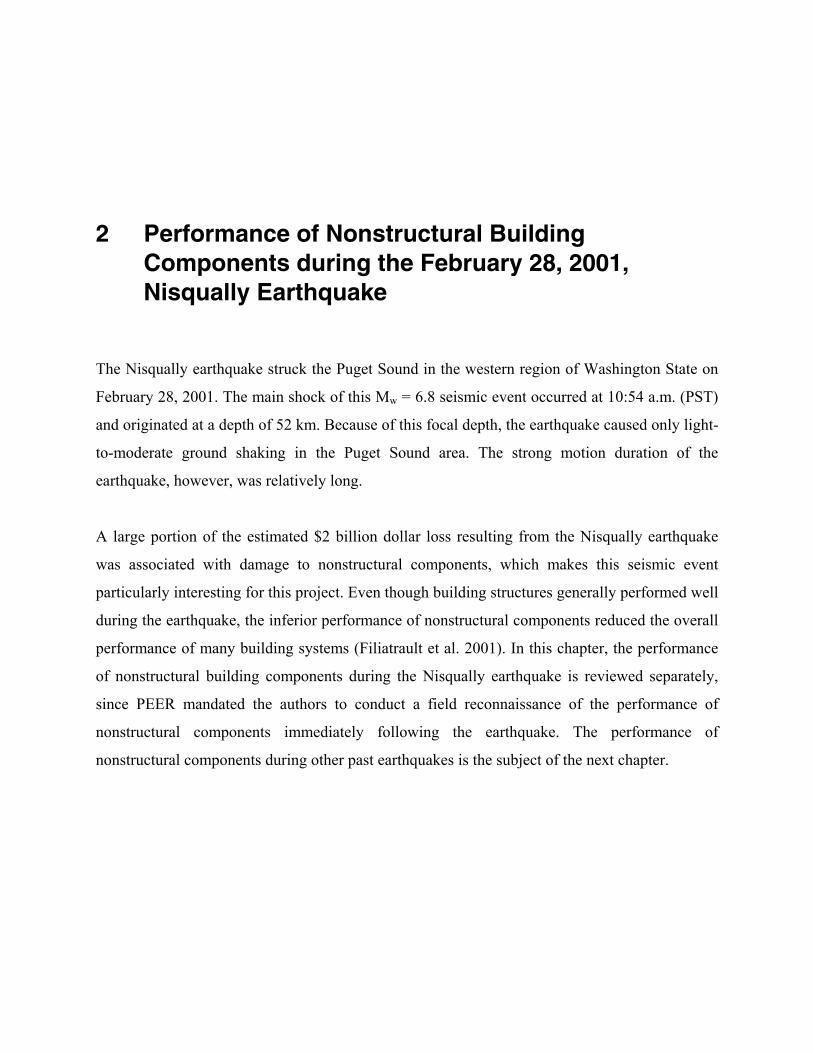
2.1 PERFORMANCE OF CEILING SYSTEMS
One of the most common types of nonstructural component failure observed following the
Nisqually earthquake was related to suspended ceiling systems. Examples of partial suspended
ceiling failure at Sea-Tac Airport are shown in Figs. 2.1 and 2.2.
Figure 2.1 Partial Failure of Suspended Ceiling at Sea-Tac Airport (Filiatrault et al. 2001).
Figure 2.2 Partial Failure of Metal Suspended Ceiling at Sea-Tac Airport
(Filiatrault et al. 2001).
One of the buildings that experienced the most damage related to suspended ceiling light fixtures
was the Starbucks Headquarters building in downtown Seattle. Although the eccentrically braced
steel frames used to seismically upgrade the building performed as intended, the suspended

7
lighting fixtures were unable to accommodate the induced lateral acceleration and caused
significant damage, as shown in Fig. 2.3. Fortunately, only minor injuries resulted from the
failure of suspended lighting fixtures throughout the building. The building also suffered damage
caused by the shifting and tumbling of unanchored furniture items and contents, as shown
in Fig. 2.4.
Figure 2.3 Failure of Suspended Lighting Fixtures in Starbucks Headquarters, Seattle (Filiatrault et al. 2001).
Figure 2.4 Damage Caused by Unanchored Furniture Items and Building Contents in Starbucks Headquarters, Seattle (Filiatrault et al. 2001).
8
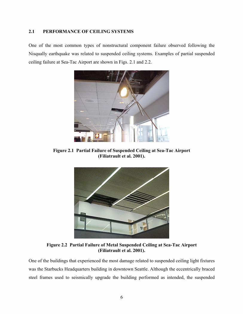
2.2 PERFORMANCE OF INTERIOR WALL FINISHES
Cracking of interior wall finish materials was observed in many buildings following the
Nisqually earthquake. In most cases, diagonal cracking occurred at upper corners of doors and
window openings and at the intersection of beams and walls, as shown in Fig. 2.5.
Figure 2.5 Cracking of Drywall Finish in Beam-to-Wall Connection at Sea-Tac Airport
(Filiatrault et al. 2001).
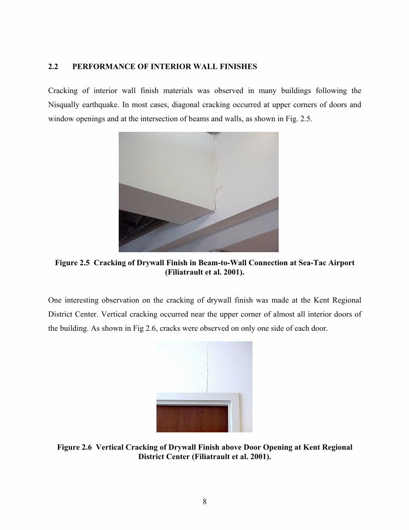
One interesting observation on the cracking of drywall finish was made at the Kent Regional
District Center. Vertical cracking occurred near the upper corner of almost all interior doors of
the building. As shown in Fig 2.6, cracks were observed on only one side of each door.
Figure 2.6 Vertical Cracking of Drywall Finish above Door Opening at Kent Regional District Center (Filiatrault et al. 2001).
9
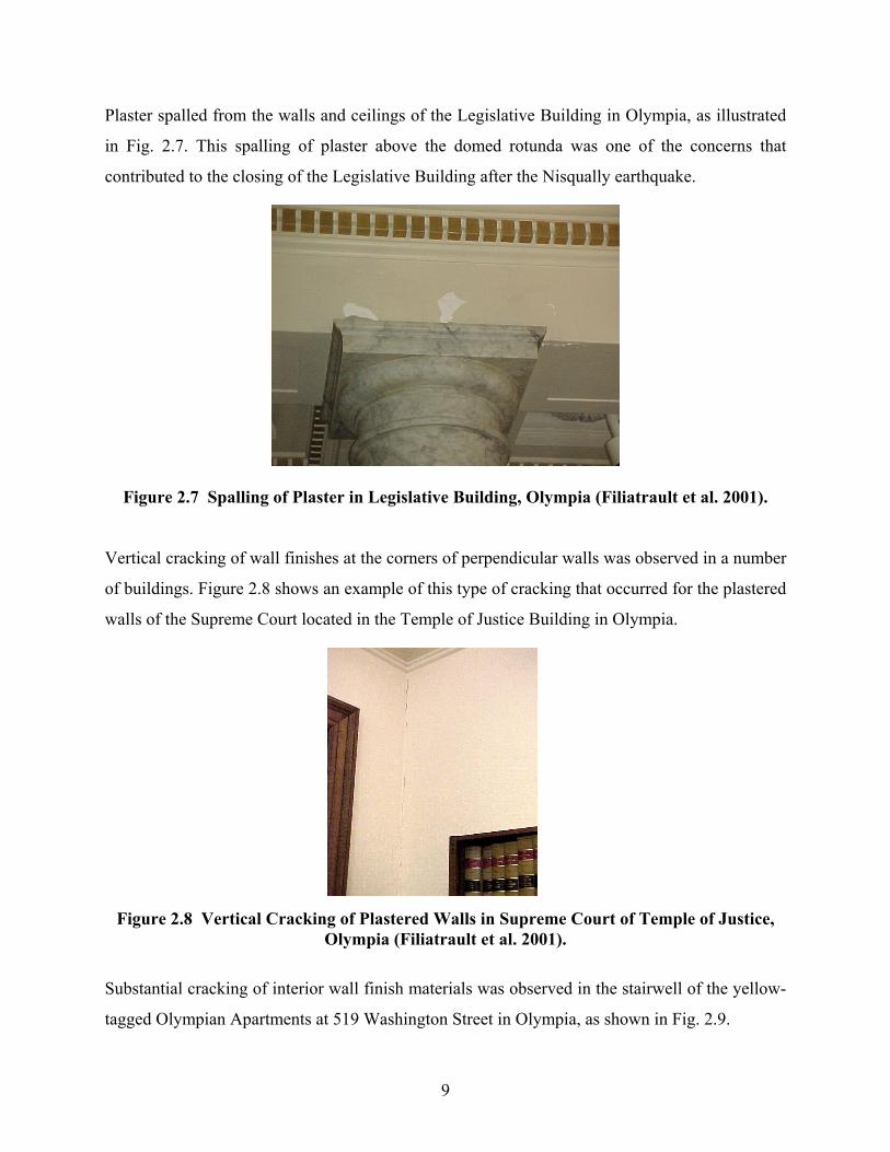
Plaster spalled from the walls and ceilings of the Legislative Building in Olympia, as illustrated
in Fig. 2.7. This spalling of plaster above the domed rotunda was one of the concerns that
contributed to the closing of the Legislative Building after the Nisqually earthquake.
Figure 2.7 Spalling of Plaster in Legislative Building, Olympia (Filiatrault et al. 2001).
Vertical cracking of wall finishes at the corners of perpendicular walls was observed in a number
of buildings. Figure 2.8 shows an example of this type of cracking that occurred for the plastered
walls of the Supreme Court located in the Temple of Justice Building in Olympia.
Figure 2.8 Vertical Cracking of Plastered Walls in Supreme Court of Temple of Justice,
Olympia (Filiatrault et al. 2001).
Substantial cracking of interior wall finish materials was observed in the stairwell of the yellow-
tagged Olympian Apartments at 519 Washington Street in Olympia, as shown in Fig. 2.9.
10
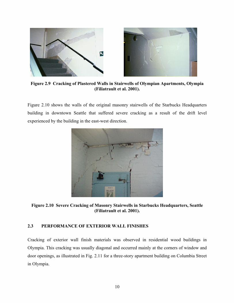
Figure 2.9 Cracking of Plastered Walls in Stairwells of Olympian Apartments, Olympia (Filiatrault et al. 2001).
Figure 2.10 shows the walls of the original masonry stairwells of the Starbucks Headquarters
building in downtown Seattle that suffered severe cracking as a result of the drift level
experienced by the building in the east-west direction.
Figure 2.10 Severe Cracking of Masonry Stairwells in Starbucks Headquarters, Seattle (Filiatrault et al. 2001).
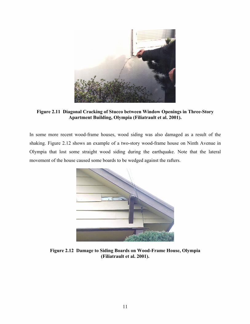
2.3 PERFORMANCE OF EXTERIOR WALL FINISHES
Cracking of exterior wall finish materials was observed in residential wood buildings in
Olympia. This cracking was usually diagonal and occurred mainly at the corners of window and
door openings, as illustrated in Fig. 2.11 for a three-story apartment building on Columbia Street
in Olympia.
11
Figure 2.11 Diagonal Cracking of Stucco between Window Openings in Three-Story Apartment Building, Olympia (Filiatrault et al. 2001).
In some more recent wood-frame houses, wood siding was also damaged as a result of the
shaking. Figure 2.12 shows an example of a two-story wood-frame house on Ninth Avenue in
Olympia that lost some straight wood siding during the earthquake. Note that the lateral
movement of the house caused some boards to be wedged against the rafters.
Figure 2.12 Damage to Siding Boards on Wood-Frame House, Olympia (Filiatrault et al. 2001).
12
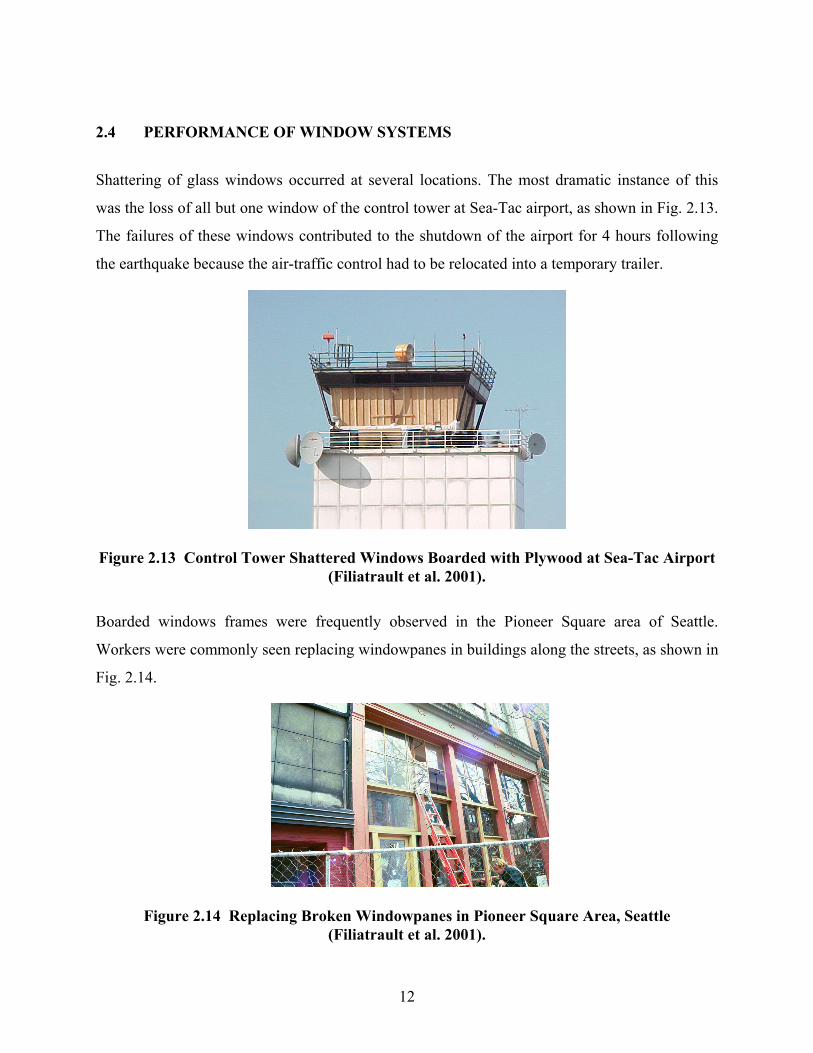
2.4 PERFORMANCE OF WINDOW SYSTEMS
Shattering of glass windows occurred at several locations. The most dramatic instance of this
was the loss of all but one window of the control tower at Sea-Tac airport, as shown in Fig. 2.13.
The failures of these windows contributed to the shutdown of the airport for 4 hours following
the earthquake because the air-traffic control had to be relocated into a temporary trailer.
Figure 2.13 Control Tower Shattered Windows Boarded with Plywood at Sea-Tac Airport (Filiatrault et al. 2001).
Boarded windows frames were frequently observed in the Pioneer Square area of Seattle.
Workers were commonly seen replacing windowpanes in buildings along the streets, as shown in
Fig. 2.14.
Figure 2.14 Replacing Broken Windowpanes in Pioneer Square Area, Seattle (Filiatrault et al. 2001).
13
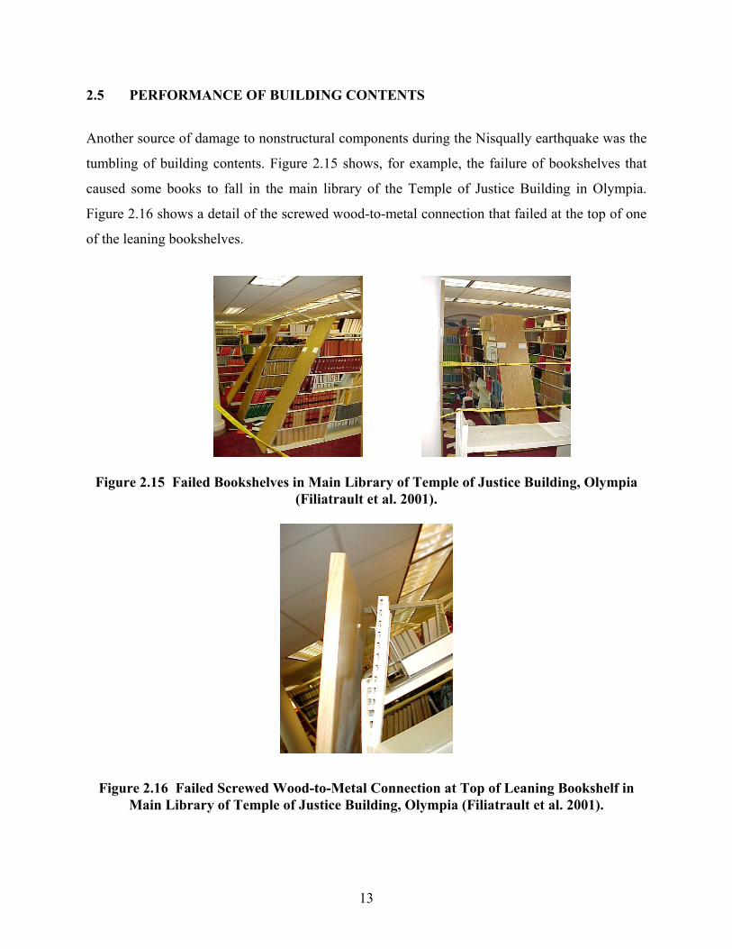
2.5 PERFORMANCE OF BUILDING CONTENTS
Another source of damage to nonstructural components during the Nisqually earthquake was the
tumbling of building contents. Figure 2.15 shows, for example, the failure of bookshelves that
caused some books to fall in the main library of the Temple of Justice Building in Olympia.
Figure 2.16 shows a detail of the screwed wood-to-metal connection that failed at the top of one
of the leaning bookshelves.
Figure 2.15 Failed Bookshelves in Main Library of Temple of Justice Building, Olympia (Filiatrault et al. 2001).
Figure 2.16 Failed Screwed Wood-to-Metal Connection at Top of Leaning Bookshelf in Main Library of Temple of Justice Building, Olympia (Filiatrault et al. 2001).
14
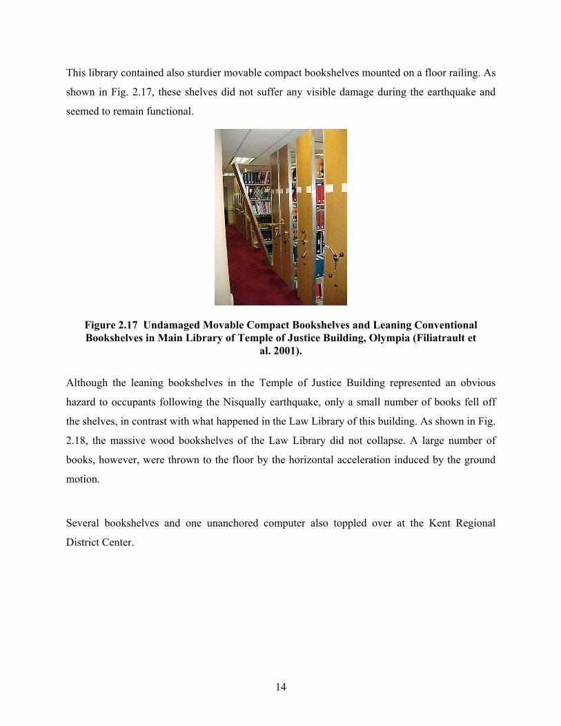
This library contained also sturdier movable compact bookshelves mounted on a floor railing. As
shown in Fig. 2.17, these shelves did not suffer any visible damage during the earthquake and
seemed to remain functional.
Figure 2.17 Undamaged Movable Compact Bookshelves and Leaning Conventional Bookshelves in Main Library of Temple of Justice Building, Olympia (Filiatrault et
al. 2001).
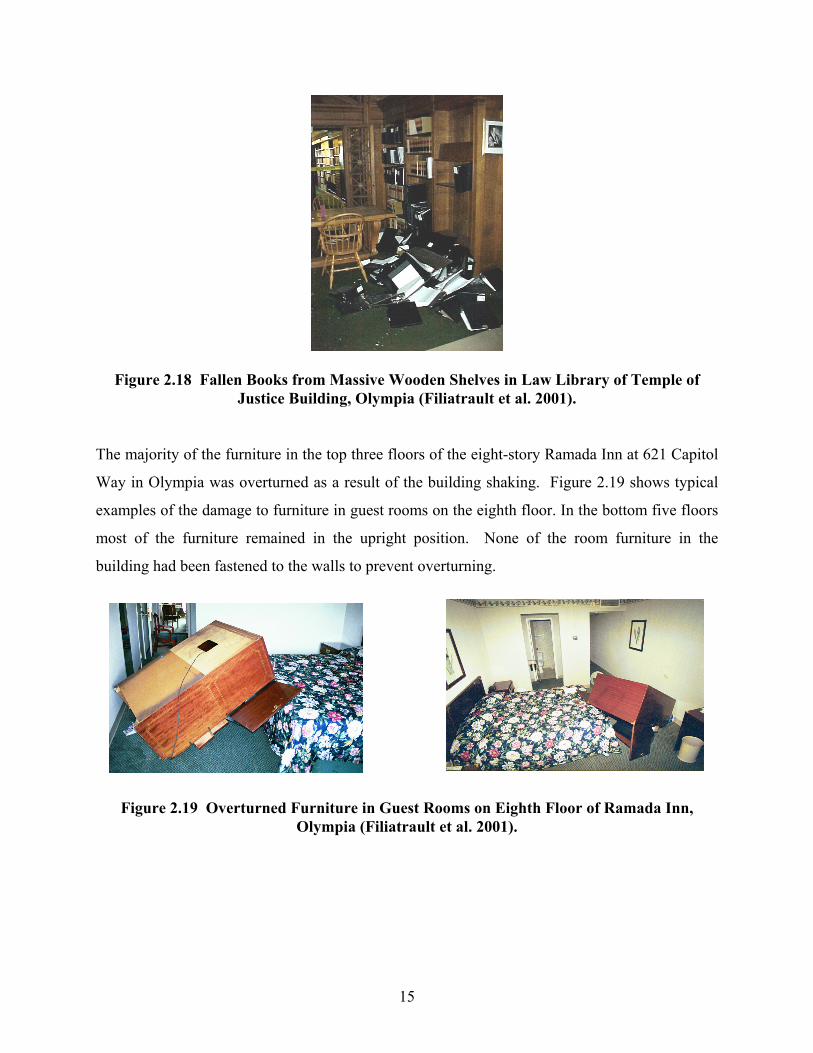
Although the leaning bookshelves in the Temple of Justice Building represented an obvious
hazard to occupants following the Nisqually earthquake, only a small number of books fell off
the shelves, in contrast with what happened in the Law Library of this building. As shown in Fig.
2.18, the massive wood bookshelves of the Law Library did not collapse. A large number of
books, however, were thrown to the floor by the horizontal acceleration induced by the ground
motion.
Several bookshelves and one unanchored computer also toppled over at the Kent Regional
District Center.
15
Figure 2.18 Fallen Books from Massive Wooden Shelves in Law Library of Temple of Justice Building, Olympia (Filiatrault et al. 2001).
The majority of the furniture in the top three floors of the eight-story Ramada Inn at 621 Capitol
Way in Olympia was overturned as a result of the building shaking. Figure 2.19 shows typical
examples of the damage to furniture in guest rooms on the eighth floor. In the bottom five floors
most of the furniture remained in the upright position. None of the room furniture in the
building had been fastened to the walls to prevent overturning.
Figure 2.19 Overturned Furniture in Guest Rooms on Eighth Floor of Ramada Inn, Olympia (Filiatrault et al. 2001).
16
2.6 PERFORMANCE OF GAS AND WATER SYSTEMS
Only one reported fire erupted at the Cedar Creek Correction Center following the earthquake.
One gas shut-off valve was activated at the Kent Regional District Center. It was reported that
the residents of 50 mobile homes in Tumwater Mobile Estates were evacuated when a 30-mm
gas line ruptured during the earthquake.
Several water lines were severed during the ground shaking. One water line and one chilled
water line failed on the fourth floor of the Kent Regional District Center.
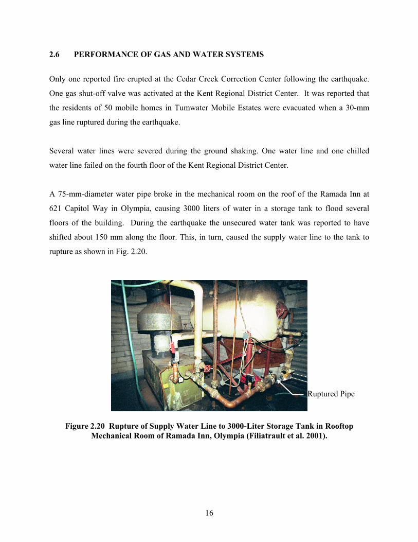
A 75-mm-diameter water pipe broke in the mechanical room on the roof of the Ramada Inn at
621 Capitol Way in Olympia, causing 3000 liters of water in a storage tank to flood several
floors of the building. During the earthquake the unsecured water tank was reported to have
shifted about 150 mm along the floor. This, in turn, caused the supply water line to the tank to
rupture as shown in Fig. 2.20.
Figure 2.20 Rupture of Supply Water Line to 3000-Liter Storage Tank in Rooftop Mechanical Room of Ramada Inn, Olympia (Filiatrault et al. 2001).
Ruptured Pipe
17
3 Performance of Nonstructural Building Components during Other Past Earthquakes
Post-earthquake observations and data collections have had the strongest influence in the
evolution of seismic design practices for nonstructural components. In almost all earthquakes, it
was found that the performance of engineered (or code-conforming) nonstructural components
that have been installed properly have been far superior than the performance of nonstructural
components installed without any seismic design in mind (Reitherman and Sabol 1995).
In this chapter, a summary of the main observations made on the seismic performance of
nonstructural components following major earthquakes that occurred in or are relevant to the
United States, other than the recent Nisqually earthquake, are briefly discussed. More complete
descriptions can be found elsewhere (Ayres et al. 1973; Ayres and Sun 1973; Ding and Arnold
1990; Reitherman 1994, 1997; Reitherman and Sabol 1995).
3.1 PERFORMANCE OF BUILDING CONTENTS
Shaking from a strong earthquake causes unsecured building contents to be shifted or thrown
around, raising significantly the hazard level to occupants. Inadequately braced shelving and
racks are particularly vulnerable. Observations of residential dwellings after the 1994
Northridge, California, earthquake revealed that kitchens suffered the most contents damage,
followed by living and dining rooms (Reitherman and Sabol 1994). Contents damage is not
always correlated to the shaking intensity. For example, in the epicentral region of the 1994
Northridge earthquake contents damage to many buildings was surprisingly low (Reitherman and
Sabol 1994).
18
The performance of cantilevered library shelving and storage rack systems during earthquakes in
the past 25 years has been poor. Field reports from the 1987 Whittier Narrows, 1989 Loma
Prieta, and 1994 Northridge earthquakes indicated that failure of these systems resulted in
inventory losses, disruption of operations as well as injuries to occupants. The main reasons for
these failures have been identified as (Rihal and Gates, 1998):
• In-plane racking and failure of diagonal rod-bracing connections;
• Out-of-plane failure and collapse due to inadequate anchorage at the base and inadequate
overhead lateral bracing between shelving units; and
• Combination of in-plane and out-of-plane damage by torsional response.
Furthermore, it was observed that in cases where the performance of these shelving and storage
rack systems was good (i.e., no failures) the material toppling was consistently more significant.
3.2 PERFORMANCE OF BUILDING SERVICE EQUIPMENT
3.2.1 Performance of Elevator and Escalator Systems
Elevators are among the most important mechanical systems in building structures and are quite
susceptible to earthquake-induced damage. It is estimated that half a million passenger elevators
are in service in the United States (Swerrie 1991), many of which are located in active seismic
zones. During the 1989 Loma Prieta earthquake, for example, close to 20,000 elevators were
located in the region of intense ground shaking (Swerrie 1991). So far elevators have performed
very well from the point of view of life-safety performance level, as there are no reported direct
fatalities associated with elevator failures in the United States (Suarez and Singh 2000). With
respect to the immediate-occupancy performance level, however, elevators remain vulnerable to
service disruptions. The main components of an elevator system have been described by Suarez
and Singh (2000). For example, in the 1971 San Fernando earthquake 674 cases of derailment of
elevator counterweights were reported (Ayres and Sun 1973); in the 1994 Northridge
earthquake, 688 (McTiernan 1994).
19
Damage suffered by elevators during the 1964 Alaska (Ayres et al. 1973), 1971 San Fernando
(Ayres and Sun 1973, Sturgeon 1972, Gates and McGavin 1998), 1978 Miyagi (Fukuda 1990),
1986 Carpathian (Nazarova 1990), 1987 Whittier (Schiff 1988), 1989 Loma Prieta (Ding and
Arnold 1990, Swerrie 1991), 1994 Northridge (Gates and McGavin 1998; Finley at al. 1996,
OSHPD 1995), and 1995 Kobe (Wada and Kitamura 1995) earthquakes has been reviewed by
Suarez and Singh (2000). The observed damage can be summarized as follows:
• Damage to guide rail anchorage
• Bent guide rails
• Counterweights dislodging from their guardrails
• Loose counterweights impacting passenger cars
• Control panels tipped or moved
• Traction machines shaken loose from their mountings
• Motor-generator sets shifted across machine room floor
• Ropes damaged by projections or protuberances in the hoist ways
• Suspension ropes jumped from drive
• Seismic switches failed to trigger
Past earthquakes, on the other hand, did not significantly affect escalator systems, until the 1994
Northridge earthquake and the 1995 Kobe earthquake in Japan where damage to many escalators
were observed. The fact that both earthquakes occurred early in the morning contributed to the
lack of injuries to escalator passengers.
3.2.2 Performance of Mechanical, Electrical, and Appliance Equipment
Large, tall and/or narrow equipment that is not adequately anchored can slide or overturn during
an earthquake and cause damage to the equipment itself or to its connections. Mechanical or
electrical equipment mounted on vertical vibration isolators can be particularly vulnerable to
being shaken off their isolated supports. Suspended equipment swaying during and after an
20
earthquake can cause damage. Unanchored water heaters may slide and overturn and result in
broken water and gas lines; the latter representing a significant fire hazard.
During the 1994 Northridge earthquake, mechanical and electrical equipment that was rigidly
bolted or anchored to the main structural system performed well, provided that the anchors and
supports were designed for code-prescribed loads (Gates and McGavin 1998). On the other hand,
equipment mounted on vibration isolation systems such as rubber or springs performed poorly
(Reitherman and Sabol 1995, Gates and McGavin 1998). This is mainly due to the unrestrained
large displacements that were induced by the ground shaking as well as amplified inertia forces
that caused failure of the anchors. As noted by Gates and McGavin (1998), vibration isolation
systems are usually designed by mechanical engineers for reducing occupant discomfort under
the machine-induced vibrations, and are then simply treated as flexibly mounted elements when
computing the seismic forces. These systems had very large dynamic amplification responses
that may have exceeded the amplification factors predicted by codes. This highlights also the
need for more coordinated efforts among the various specialties involved in the design and
installation of nonstructural components.
Damage to mechanical and electrical equipment has been widespread in all past strong
earthquakes that have struck the United States in the twentieth century. In the 1994 Northridge
earthquake, for example, damage was particularly extensive to spring-isolated mechanical
equipment installed in upper stories or roofs of buildings (Reitherman and Sabol 1995).
During the 1994 Northridge earthquake, approximately 2500 water heaters were damaged (Mroz
and Soong, 1997). In past California earthquakes, water heaters were a major source of gas
leaks, posing an important post-earthquake fire hazard. Of this large number of damaged water
heaters, the number of those equipped with some kind of restraints was similar to the number of
those without any restraint. This is an indicator that non-engineered restraints were not effective
in protecting water heaters.
21
3.2.3 Performance of Ductwork and Piping Systems
The seismic performance of ductwork and piping systems is of special interest. These systems
are expected to remain functional following earthquakes in order to mitigate post-earthquake fire
hazard. Also, there is a real potential for significant water damage that can take place if these
systems are compromised in a building that did not suffer significant structural damage.
During the 1994 Northridge earthquake, probably the single most disruptive type of
nonstructural damage was breakage of water lines inside buildings (Reitherman and Sabol 1995).
At least 13 hospitals suffered extensive water damage caused by failures in the pressurized fire
sprinkler, and HVAC and domestic water piping systems (Ayres and Philips 1997). Extensive
failures occurred in connections in small hot water lines and duct-mounted zone reheat coils.
Differential movements between the pipes and the buildings caused also failures of sprinkler
systems. The weak link in the fire sprinkler system was identified as being the small branch lines
feeding water into the room area within the suspended ceiling (Gates and McGavin 1998). The
smaller feeders, typically connected to the main branch by 90o bends, experienced large bending
stresses because of the interaction of the sprinkler system and the suspended ceiling. In the cases
where these bends had been designed to provide a flexible connection no failures were observed.
The most dangerous failure of a piping system occurred when a 12-in. pipe fell from a mall’s
ceiling, demolishing a kiosk. A surprising observation during the Northridge earthquake is the
significant effect of vertical accelerations on sprinkler systems. Many sprinklers were damaged
when branch lines moved upward, pushing sprinklers through the ceiling. In general, the lack of
bracing or inadequate bracing was cited as a major factor in the most significant failures of fire
sprinkler systems during the 1994 Northridge earthquake in California (Fleming 1998) and the
1995 Kobe earthquake in Japan (EQE 1995). Also, failure of unbraced small diameter piping
(less than 1-in. diameter) was also common in the Northridge earthquake.
22
3.3 PERFORMANCE OF BUILDING UTILIZATION EQUIPMENT
3.3.1 Performance of Emergency Power Systems
The failure of emergency power systems during an earthquake can be particularly disruptive,
since these systems are designed to be activated in the event of an emergency. Emergency power
systems include heavy components such as batteries, motor generators, fuel tanks, transformers,
switchgear, and control panels that are frequently stored in racks.
The loss of offsite electric power during the 1994 Northridge earthquake put the emergency
power supply systems to the test especially for essential operations. The power outage affected
over 2 million customers in the Los Angeles area (Reitherman and Sobel 1995). As reported by
Merz and Eli (1997), the following observations were made on the performance of emergency
power systems after surveying a series of electric power facilities, industrial facilities, power
plants, and lifelines after the 1994 Northridge earthquake:
• Emergency generators directly anchored or on engineered isolators with seismic
restraints performed well.
• A transfer switch from normal offsite power to emergency power did not function.
• A pumping system transferring fuel from a storage tank to a day tank was non-
operational because it was not powered by an emergency power system.
• Failure of a switch from an empty fuel tank to an auxiliary tank caused another
emergency generator to be non-functional.
• Electric shorting in electrical enclosures due to water leaks from domestic water and fire
sprinklers caused the shutdown of certain power systems.
3.3.2 Performance of Hazardous Material Storage Systems
The failure of hazardous materials supply lines and the improper operation of seismically
activated shutoff valves can be life threatening following an earthquake. Toppling of laboratory
chemicals must also be prevented during seismic shaking. Tall vertical tanks used for storing
fluids are susceptible to overturning under seismic loading when the height to diameter ratio is
23
large. In both the 1989 Loma Prieta and 1994 Northridge earthquakes a number of fluid storage
tanks toppled as a result of inadequate anchoring (Gates and McGavin 1998).
3.4 PERFORMANCE OF INTERIOR ARCHITECTURAL ELEMENTS
3.4.1 Performance of Interior Partitions
Heavy interior masonry partitions have often failed in past earthquakes due to the excessive
flexural out-of-plane stresses or excessive in-plane shear stresses induced by the interstory drifts
imposed on the building structure. This type of failure has been observed in numerous
earthquakes in the United States, and as far back as the 1925 Santa Barbara earthquake (Dewell
and Willis 1925).
3.4.2 Performance of Ceiling Systems
Unbraced suspended ceilings can swing independently of the supporting floor and induce
damage, particularly at the perimeters of ceilings. Lay-in ceilings are particularly vulnerable to
the relative displacement of the supporting grid members. During the 1994 Northridge
earthquake, millions of square feet of ceiling tiles were dislodged along with lighting fixtures
and air vent ducts (Gates and McGavin 1998). The effect of the fire sprinkler system that
penetrates the ceiling tiles to expose the sprinkler head caused irreparable damage to the tiles
while rupturing some of the sprinkler systems, causing subsequent water damage. Recent code
changes require spacing between the sprinkler head and the ceiling tile to accommodate the
differential movements during seismic loading. Similarly, no spacing is typically provided to
accommodate differential movement between the ceiling grid and the perimeter walls. This also
contributed to the extensive damage to ceiling systems during the 1994 Northridge earthquake.
3.4.3 Performance of Lighting Fixtures
Fluorescent lighting fixtures that are supported by a suspended ceiling grid can lose their vertical
support when the suspended ceiling sways and distorts under ground motion shaking. The splices
24
of electrical wires used to support pendant-mounted lighting fixtures can pull apart causing the
fixtures to fall. Lighting fixtures can also swing and impact adjacent objects often causing the
fixtures to fall or fail.
Failure of light fixtures was one of the three most frequent kinds of nonstructural damage
suffered by school buildings as the result of the 1994 Northridge earthquake (DSA 1994). A new
type of lighting fixture damage that was observed during the 1994 Northridge earthquake was
the fall from high gymnasium ceilings of high-intensity discharge gas vapor light (Reitherman
and Sabol 1995).
3.4.4 Performance of Raised Computer Access Floors
Typical raised computer access floors are constructed of wood, aluminum or steel panels
supported on adjustable column pedestals. The columns are often fastened to the sub-floor with
mastic. When subjected to lateral loads, raised access floors can be very flexible and can cause
an amplification of the ground motion at the base of equipment items supported on the floor. In
turn, the base shear induced by these equipment items may cause the raised access floor to
collapse.
3.5 PERFORMANCE OF EXTERIOR ARCHITECTURAL ELEMENTS
Nonstructural elements used for the exterior construction of a building can suffer significant
damage during an earthquake that may result in life-threatening hazards. Observations from past
earthquakes have shown that excessive differential motions combined with the lack of lateral
strength are responsible for most of the seismic damage suffered by these elements.
3.5.1 Performance of Exterior Curtain Walls
Stiff curtain wall panels attached to the exterior of a building may have insufficient lateral
deformation capacity to accommodate the lateral interstory drift imposed on the building by the
25
seismic ground motion input. This problem can be particularly acute when the building is
flexible laterally (e.g., a steel moment-resisting frame). Usually failure is observed in the
connections between the panels and the building structure.
A review of damage suffered by heavy cladding panels during the 1994 Northridge earthquake
indicated that nonstructural cladding panel influenced significantly the performance of several
buildings, and that efforts should be undertaken to provide proper engineering details to these
elements that currently are ignored in design (Cohen 1995).
A study by Goodno et al. (1989) correlated damage to heavy cladding components observed
during the 1985 Mexico earthquake to experimental and analytical results. It was found that in
many cases, claddings increased the initial stiffness of the building before suffering extensive
damage. This stiffening effect is usually not taken into account during the design process, and
may considerably influence the dynamic response of the building. It was also noted that although
the damaged cladding systems were replaced following the earthquake, the engineering effort to
fully assess the retrofit or repair was minimal. As a result of this, the authors believe that many
of the connections of the replaced or repaired cladding systems to the main structural system
may be inadequate.
3.5.2 Performance of Exterior Veneers
Stone and masonry veneers with inadequate anchorage have often failed in past earthquakes. A
most unfortunate example of this occurred during the 1987 Whittier Narrows earthquake in
California when a precast concrete panel fell from a parking structure and killed a student (Taly
1988).
Out-of-plane failure of precast cladding, brick and masonry veneers was widespread in the
epicentral region of the 1994 Northridge earthquake (Reitherman and Sabol 1995). Goodno
26
(1994) provides a survey of the damage suffered by heavy cladding systems during this
earthquake.
3.5.3 Performance of Glass Doors, Windows, and Glazing
The principal cause of glass door and window failures during earthquakes is the inadequate edge
clearances around the glass to allow the building to deform laterally without bearing on the glass.
Glazing damage was extensive during the 1994 Northridge earthquake. In some cases glazing
damage was so severe that the supporting metal frames buckled. In some areas, however, only a
small proportion of buildings that suffered glazing damage were red-tagged (Reitherman and
Sabol 1995). These buildings could have been hazardous in the event of a strong aftershock.
Low-rise buildings that incorporated annealed glass (rather than tempered, wired, or laminated
glass required for taller buildings) produced sharp-edged pieces that could have caused serious
injuries. Film-coated windows, on the other hand, performed well (Reitherman and Sabol 1995).
Window breakage due to flying contents was also observed. Highrise glazing generally
performed well during the Northridge earthquake. An industry survey after the earthquake
revealed that glazing incorporating silicon sealant performed better than glazing with vinyl
gaskets (Harter 1994, Vallabhan 1994). Systems equipped with Mylar film to provide seismic
protection from sharp glass debris performed very well in the case of small windowpanes, but
proved less effective for larger ones, where the entire pane was dislodged and fell as one big
piece (Gates and McGavin 1998).
3.5.4 Performance of Chimneys
The vulnerability of brick chimneys has been demonstrated in all strong earthquakes that struck
the United States in the twentieth century. Even tall precast concrete chimneys used in recent
residential construction were damaged during the Northridge earthquake by rotating at their base
and separating themselves from the main structure (Reitherman and Sabol 1995).
27
4 Inventory and Comparison of Existing Regulations and Guidelines for the Seismic Design and Specification of Nonstructural Building Components
Before 1961 the Uniform Building Code (UBC) did not contain any specific seismic design
requirements for nonstructural components. The 1961 edition of the UBC introduced a seismic
force analysis procedure applicable to nonstructural building components. The 1964 Alaska and
the 1971 San Fernando earthquakes demonstrated for the first time that damage to nonstructural
building components could result in casualties and injuries, disruption of building operation, and
significant economic losses (Lagorio 1990).
In the last decade, a number of federal agencies, including the United States Postal Service, have
developed and implemented guidelines for the seismic evaluation and retrofit of nonstructural
building components (Applied Technology Council 1992a, 1992b). A summary of recent
developments in codes for nonstructural components can also be found in Soong (1994a).
4.1 SEISMIC PERFORMANCE REQUIREMENTS FOR NONSTRUCTURAL BUILDING COMPONENTS
Table 11-1 of the NEHRP Guidelines for Seismic Rehabilitation of Buildings and its commentary
(ATC 1997a, 1997b) lists requirements for the applicability of life-safety, immediate-occupancy
requirements, and methods of analysis for a variety of architectural, mechanical, and electrical
building components. These performance requirements are established in relation to three
different seismic zones. The NEHRP guidelines address only components that are permanently
installed in buildings. Other nonstructural components, such as building contents introduced by
28
owners, are not covered by the guidelines. The NEHRP guidelines define four different
performance levels for nonstructural building components:
1. Reduced-Hazards Performance Level: Extensive Damage but prevention of immediate
falling hazard from heavy items.
2. Life-Safety Performance Level: Prevention of falling hazard from all items that can
directly result in injury.
3. Immediate-Occupancy Performance Level: No falling hazard, minor damage and
disruption to nonstructural components, but the building can be occupied.
4. Operational Performance Level: Continuing operation of all nonstructural components.
4.2 DESIGN FORCE AND DRIFT REQUIREMENTS
Several seismic design force requirements have been developed in the United States for
nonstructural components. These provisions have evolved mainly from those included in the
Uniform Building Code (UBC) and those developed as part of the National Hazard Reduction
Program (NEHRP). The NEHRP provisions have been developed on a strength base, while, until
the 1997 edition of the UBC, the UBC provisions have been based on allowable stress design. In
this section, the current seismic design force and drift requirements in the United States are
reviewed. Comparative studies on the application of these requirements can be found elsewhere
(Soong 1994, Singh et al. 1993, Freeman and Kehoe 1997, Phan and Taylor, 1996, Taylor and
Phan 1997, Backman and Drake 1998, Drake and Bragagnolo 2000).
4.2.1 The SEAOC Blue Book (1996)
The SEAOC Blue Book (SEAOC 1996), prepared by the Structural Association of California,
reproduces section 1630 of the 1994 edition of the Uniform Building Code (ICBO 1994) and
describes the lateral forces that must be applied on elements of structures, nonstructural
components, and equipment supported by structures. The 1994 UBC provisions are based on
allowable stress design. The allowable stress design seismic force on building parts, ,Fp
specified in the SEAOC Blue Book is given by:
pgfppp WCCCIZF = (4.1)
29
where
Z = Seismic zoning factor, 0.4 in Zone 4
pI = Importance factor, 1.0 except for essential or hazardous parts where it takes a value of 1.5
pC = Seismic coefficient for parts, function of nonstructural element flexibility, energy
dissipation capacity, and location in building, value varies from 0.75 to 2.0
fC = Flexibility coefficient, 1.0 for rigid equipment (period less than 0.06 s) and 2.0 for
flexible equipment
gC = At-grade coefficient, 1.0 for flexible parts above grade, 0.67 for parts laterally supported
or below grade
pW = Operating weight of the part
Equation (4.1) assumes constant floor acceleration along the height of the building.
4.2.2 The Uniform Building Code (1997)
Section 1632 of the 1997 edition of the Uniform Building Code (ICBO 1997) provides lateral
force requirements for elements of structures, nonstructural components, and equipment
weighing more than 400 lbs and supported by structures. The 1997 UBC provisions are based on
strength design. The strength design seismic force on building parts, ,Fp specified in the
SEAOC Blue Book is given by:
pr
x
p
papp W
hh
RICa
F
+= 31 (4.2)
with
ppapppa WICFWIC. 470 ≤≤ (4.3)
30
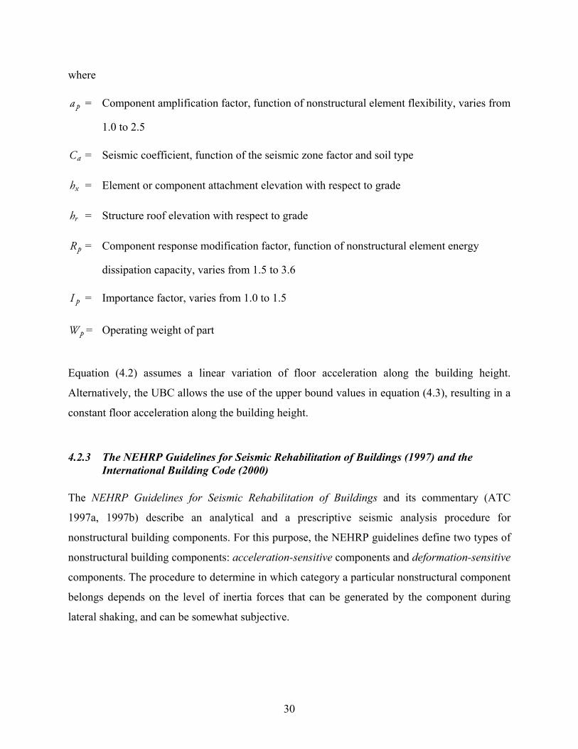
where
pa = Component amplification factor, function of nonstructural element flexibility, varies from
1.0 to 2.5
aC = Seismic coefficient, function of the seismic zone factor and soil type
xh = Element or component attachment elevation with respect to grade
rh = Structure roof elevation with respect to grade
pR = Component response modification factor, function of nonstructural element energy
dissipation capacity, varies from 1.5 to 3.6
pI = Importance factor, varies from 1.0 to 1.5
pW = Operating weight of part
Equation (4.2) assumes a linear variation of floor acceleration along the building height.
Alternatively, the UBC allows the use of the upper bound values in equation (4.3), resulting in a
constant floor acceleration along the building height.
4.2.3 The NEHRP Guidelines for Seismic Rehabilitation of Buildings (1997) and the International Building Code (2000)
The NEHRP Guidelines for Seismic Rehabilitation of Buildings and its commentary (ATC
1997a, 1997b) describe an analytical and a prescriptive seismic analysis procedure for
nonstructural building components. For this purpose, the NEHRP guidelines define two types of
nonstructural building components: acceleration-sensitive components and deformation-sensitive
components. The procedure to determine in which category a particular nonstructural component
belongs depends on the level of inertia forces that can be generated by the component during
lateral shaking, and can be somewhat subjective.
31
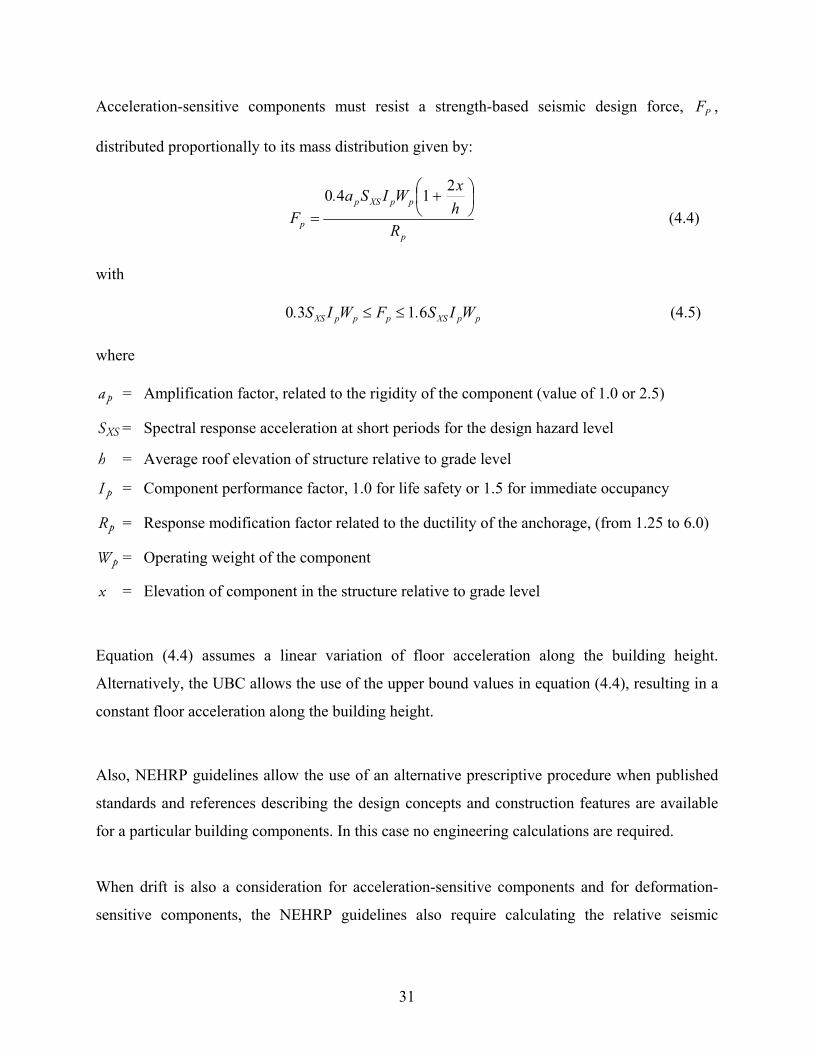
Acceleration-sensitive components must resist a strength-based seismic design force, PF ,
distributed proportionally to its mass distribution given by:
p
ppXSp
p RhxWISa.
F
+
=
2140 (4.4)
with
ppXSpppXS WIS.FWIS. 6130 ≤≤ (4.5)
where
pa = Amplification factor, related to the rigidity of the component (value of 1.0 or 2.5)
XSS = Spectral response acceleration at short periods for the design hazard level
h = Average roof elevation of structure relative to grade level
pI = Component performance factor, 1.0 for life safety or 1.5 for immediate occupancy
pR = Response modification factor related to the ductility of the anchorage, (from 1.25 to 6.0)
pW = Operating weight of the component
x = Elevation of component in the structure relative to grade level
Equation (4.4) assumes a linear variation of floor acceleration along the building height.
Alternatively, the UBC allows the use of the upper bound values in equation (4.4), resulting in a
constant floor acceleration along the building height.
Also, NEHRP guidelines allow the use of an alternative prescriptive procedure when published
standards and references describing the design concepts and construction features are available
for a particular building components. In this case no engineering calculations are required.
When drift is also a consideration for acceleration-sensitive components and for deformation-
sensitive components, the NEHRP guidelines also require calculating the relative seismic
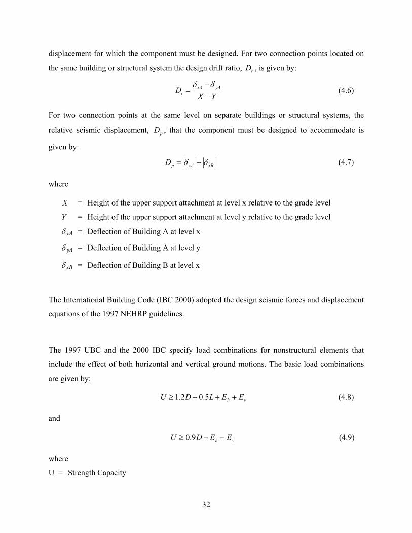
32
displacement for which the component must be designed. For two connection points located on
the same building or structural system the design drift ratio, rD , is given by:
YX
D yAxAr −
−=
δδ (4.6)
For two connection points at the same level on separate buildings or structural systems, the
relative seismic displacement, pD , that the component must be designed to accommodate is
given by:
xBxApD δδ += (4.7)
where
X = Height of the upper support attachment at level x relative to the grade level
Y = Height of the upper support attachment at level y relative to the grade level
xAδ = Deflection of Building A at level x
yAδ = Deflection of Building A at level y
xBδ = Deflection of Building B at level x
The International Building Code (IBC 2000) adopted the design seismic forces and displacement
equations of the 1997 NEHRP guidelines.
The 1997 UBC and the 2000 IBC specify load combinations for nonstructural elements that
include the effect of both horizontal and vertical ground motions. The basic load combinations
are given by:
vh EELDU +++≥ 5.02.1 (4.8)
and
vh EEDU −−≥ 9.0 (4.9)
where
U = Strength Capacity
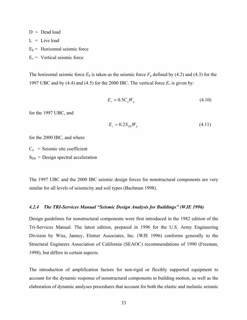
33
D = Dead load
L = Live load
Eh = Horizontal seismic force
Ev = Vertical seismic force
The horizontal seismic force Eh is taken as the seismic force Fp defined by (4.2) and (4.3) for the
1997 UBC and by (4.4) and (4.5) for the 2000 IBC. The vertical force Ev is given by:
pav WCE 5.0= (4.10)
for the 1997 UBC, and
pDSv WSE 2.0= (4.11)
for the 2000 IBC, and where
Ca = Seismic site coefficient
SDS = Design spectral acceleration
The 1997 UBC and the 2000 IBC seismic design forces for nonstructural components are very
similar for all levels of seismicity and soil types (Bachman 1998).
4.2.4 The TRI-Services Manual “Seismic Design Analysis for Buildings” (WJE 1996)
Design guidelines for nonstructural components were first introduced in the 1982 edition of the
Tri-Services Manual. The latest edition, prepared in 1996 for the U.S. Army Engineering
Division by Wiss, Janney, Elstner Associates, Inc. (WJE 1996) conforms generally to the
Structural Engineers Association of California (SEAOC) recommendations of 1990 (Freeman,
1998), but differs in certain aspects.
The introduction of amplification factors for non-rigid or flexibly supported equipment to
account for the dynamic response of nonstructural components to building motion, as well as the
elaboration of dynamic analyses procedures that account for both the elastic and inelastic seismic
34
response of the building are the two major additions to the SEAOC (1990) recommendations. In
addition, the document considers two levels of seismic input and incorporates performance
requirements, methods for estimating floor response spectra as well as design examples.
4.3 DESIGN GUIDELINES FOR BUILDING CONTENTS
Hillman, Biddison & Loevenguth (1977) have produced guidelines for the seismic restraints of
kitchen equipment complying with the 1976 edition of the Uniform Building Code. Typical
detail drawings were provided for 19 different basic kitchen equipment categories.
4.4 DESIGN GUIDELINES FOR BUILDING SERVICE EQUIPMENT
Damage to building service equipment can compromise the operation of a building immediately
after an earthquake. This interruption in operation can be detrimental to life safety for essential
buildings such as hospitals.
The FEMA-172 handbook (BSSC 1992) presents simple techniques for mitigating the potential
seismic damage that can occur to common building equipment including: elevator and escalator
systems, mechanical and electrical equipment, ductwork and piping, emergency power systems,
hazardous material storage systems and computer equipment.
In the mid-1980s, the Electric Power Institute initiated a project to evaluate the seismic safety of
nuclear power plants by collecting and evaluating existing qualification test data (Smith and
Merz 1985). In the first phase of the project, 7 different equipment classes were considered. In
the second phase, the methodology was extended to approximately 20 other classes of
equipment. The results of the study allowed the generation of generic ruggedness spectra for
each specified equipment class.
Recently Johnson et al. (1999) developed a detailed methodology for the assessment and
improvement of the functional reliability of equipment systems in critical facilities, such as
hospitals, following earthquakes. The methodology is designed to be used by regular staff
35
members, and is based on a simple and rapid assessment of equipment items. The
implementation of the methodology requires four major steps: (1) the systems required for life-
safety purposes need to be identified; (2) a rapid visual screening needs to be performed on each
individual equipment item to determine a relative score; (3) logic diagrams must be used to
develop overall scores for all systems based on the scores of individual equipment items; system
vulnerabilities can be identified based on these scores and remedial actions can be determined;
and (4) the results of the evaluation must be implemented to elaborate a risk management
strategy.
4.4.1 Specific Design Guidelines for Elevator and Escalator Systems
The ASME A17.1 Safety Code for Elevators and Escalators (American Society of Mechanical
Engineers 1996) is used in the United States to mitigate the potential earthquake-induced
damage to elevators and to enhance their seismic performance.
For seismic zones 2 and higher, the A17.1 Code requires the installation of upper and lower
position restrainers to the cars and counterweight frames of elevator systems. The purpose of
these restrainers is to prevent the counterweight and car from disengaging from the rail if the
roller guides fail in a seismic event (Suarez and Singh 2000). The specifications of the A17.1
Code require that the guide rails of elevators be constructed of T-sections conforming to
prescribed weights and dimensions. Part XXIV of the A17.1 Code includes graphs for the
selection of the minimum bracket spacing for each of the prescribed T-sections. These curves are
based on a horizontal seismic force of 0.5 g that should not cause any damage to guide rails. Part
XXIV of the A17.1 Code also provides design formulas to determine the maximum allowable
weight per pair of guide rails. The formulas depend on the direction of the applied seismic
forces. The code does not provide any commentary discussing the theoretical background for
these formulas. For seismic zones 2 and 3, the seismic section of the A17.1 Code also requires
that the guide rails possess a minimum moment of inertia. Part XXIV of the A17.1 Code
provides a set of formulas to calculate the design forces for the guide rail brackets.
36
The A17.1 Code requires two “fail-safe” earthquake protective devices for all traction elevators
operating at a speed of 150 ft/min and above: a seismic switch and a displacement switch. A
seismic switch is a mechanical or electromechanical device activated by a given threshold
ground motion to provide a signal that a potentially damaging earthquake is imminent. The
A17.1 Code requires that upon activation of a seismic switch, cars in motion must proceed to the
nearest floor, open their doors, and shut down. A displacement switch is a device actuated by the
displacement of the counterweight at any point on the hoist way to provide a signal that the
counterweight has been displaced from its normal operating plane of travel or has left its guide
rails. The A17.1 Code requires that upon activation of a displacement switch, the cars in motion
must stop and then proceed to the nearest landing at reduced speed in the direction away from
the counterweight.
At the time of writing, the current edition of the A17.1 code did not include any seismic
requirements for escalators or moving walkway systems. Recently, new seismic requirements for
escalators have been added in the 1998 edition of the California Elevator Safety Construction
Code. Suarez and Singh (2000) summarized these requirements as follows:
• The connections and beam seats between the escalator/walkway system and the building
structure must be designed for a horizontal seismic acceleration of 0.5 g, and must also
accommodate twice the interstory drift of the building structure in both directions.
• The handrail supports must be able to sustain a design load of 150 lbs/ft applied at the top
of the handrail.
• At least one seismic switch must be provided in any building containing escalators and/or
moving walkways. All escalators and/or moving walkways must stop upon activation of
the seismic switch.
• Seismic restraints must be provided in the longitudinal direction at the ends of an
escalator.
• Seismic restraints must be provided at all supports in the transverse direction.
37
4.4.2 Specific Design Guidelines for Mechanical, Electrical, and Appliance Equipment
Applicants for an operating license for a nuclear power plant in the United States are required to
submit to the Nuclear Regulatory Commission (NRC) a final safety analysis report. This report
must include a seismic qualification review of the plant and its components, including
mechanical and electrical equipment. To provide guidance to nuclear power plant applicants, the
NRC has published guidelines to conduct seismic and dynamic qualification of electrical and
mechanical equipment for nuclear power plants (Subudhi et al. 1986). These guidelines present
generic information about the dynamic environment and equipment mounting simulations,
procedures to conduct dynamic qualifications by analysis and/or testing, and the NRC evaluation
procedure.
4.4.3 Specific Design Guidelines for Ductwork and Piping Systems
The 1997 UBC includes recommendations for piping systems. The design lateral seismic force
Fp is given by:
IWCF ap 56.0= (4.12)
where
Ca = Coefficient depending on supporting structure foundation type and seismic zone factor
I = Importance factor equal to 1 for non-essential piping and 1.25 for hazardous or essential
piping
W = Deadweight of pipe
The 2000 IBC has introduced more elaborate and complex requirements for piping systems. The
design seismic force Fp is bounded by:
ppDSpppDS WISFWIS 6.13.0 ≤≤ (4.13)
38
where
SDS = Spectral response at short periods depending on foundation conditions and seismic zone
intensity
Ip = Importance factor, equal to 1 for non-essential piping and 1.5 for hazardous or essential
piping
Wp = Operating weight of the pipe
The ASCE 7-95 published by the American Society of Civil Engineers also contains
requirements for seismic design of piping. These requirements are very similar to the 2000 IBC.
Two methods are generally used for the design of pipes in practice (Stevenson 1998). The
“design by rule method” consists of determining the spacing between piping supports to
implicitly assure that the stresses and deformations in the supports and piping are within the
allowable limits. One such method has been published by the Electric Power Research Institute
(EPRI 1990). In the “design by analysis method” the loads on the supports and stress resultants
on the piping are computed by applying the seismic forces in combination with other loads and
by comparing to allowable stress values or force resistance to carry out the design. Typically, the
“design by rule method” is used for small-diameter piping and for areas of low seismicity.
Factors that typically influence the seismic design of pipes are (Stevenson 1998):
• Location of the facility, with respect to seismic zones
• Pipe size
• Pipe classification, i.e., normal, hazardous, or essential
A piping system is defined hazardous or essential if:
• It contains hazardous materials
• The operating temperature is above 650o C, or
39
• It must perform an essential safety-related function during or immediately following an
earthquake
The Sheet Metal and Air-Conditioning Contractors National Association (SMACNA 1992) has
published guidelines for the design of seismic restraints of new mechanical systems and
plumping piping systems in areas of high seismicity. These guidelines can also be used for the
rehabilitation of existing systems. The SMACNA guidelines for the seismic bracing of ductwork
can be summarized as follows:
• Seismic braces are required for rectangular ducts that have an area of 6 ft2 and greater
and for circular ducts that have a diameter of 28 in. or larger.
• Transverse braces should be installed at a maximum of 30 ft on center, at each duct turn,
and at each end of a duct run.
• Longitudinal braces should be installed at a maximum of 60 ft on center.
• No bracing is required if the top of a duct is suspended 12 in. or less from the supporting
structural member and the suspension straps are attached to the top of the duct.
The SMACNA guidelines for the seismic bracing of piping can be summarized as follows:
• Seismic braces are required for all pipes that have a diameter of 2.5 in. and larger and
also for smaller piping used for fuel gas, oil, medical gas, compressed air and/or located
in boiler rooms, mechanical equipment rooms, and refrigeration machinery rooms.
• Transverse braces should be installed at a maximum of 40 ft on center.
• Longitudinal braces should be installed at a maximum of 80 ft on center.
The Sheet Metal and Air Conditioning Contractors National Association (SMACNA 1980, 1985)
also provides prescriptive design methods for strengthening the supports and bracing of HVAC
and special ductwork systems.
40
The SP-58 (MSS 1993) document of the Manufacturers Standardization Society of the Valve and
Fitting Industry includes prescriptive methods for the strengthening of support and bracing of
piping systems.
Vagliente et al. (1986) pointed out the need for guidelines related to the seismic performance of
plastic piping, since plastic materials are now being used to replace ductile steel and copper as a
basic piping material. The lateral support of plastic piping must take into account the reduced
strength of plastic compared to steel and copper.
Prescriptive seismic design approaches to support bracing of fire suppression piping systems are
given in the National Fire Protection Association standard NFPA-13 (NFPA 1996). Fleming
(1998) described the historical development of the NFPA-13 seismic requirements for fire
sprinkler systems and proposed modifications for the future editions of the NFPA standard.
4.5 DESIGN GUIDELINES FOR BUILDING SERVICE EQUIPMENT
4.5.1 Specific Design Guidelines for Electrical and Communication Systems
The Sheet Metal and Air Conditioning Contractors National Association (SMACNA 1980, 1985)
provides prescriptive guidelines for strengthening the supports and bracing of electrical and
communication conduits.
Reitherman and Minor (1989) published technical guidelines for the seismic protection of typical
nonstructural component items encountered in communication facilities. These guidelines
present typical details for the attachment of equipment to walls, the anchoring of equipment to
concrete slabs, the anchoring of cabinet and box-like equipment, the anchoring of equipment
racks, the bolting of adjacent cabinets for increased stability, the restraining of countertop
equipment, and the installation of safety wires for overhead light fixtures. The guidelines also
present alternatives to the anchorage of equipment by taking advantage of controlled sliding and
41
rolling. A less technical companion pamphlet on the same subject was also published
(Reitherman 1987).
Parise et al. (1995) discussed the design and installation criteria to insure the functional
reliability of electrical power systems in buildings. In particular, the authors emphasize the use
of the “brush-distribution” approach to reduce drastically the seismic vulnerability of electrical
power systems in buildings. In this approach, the heaviest electrical equipment items
(transformers, generators, motors, panel boards, etc.) are to be located, as much as possible, in
ground or underground floors. Also, the electrical distribution in the upper floors of buildings
should be subdivided into vertical sectors (or towers) along the height of the building.
Chapter 4 of the “Network Equipment-Building System (NEBS) Requirements: Physical
Protection” published by Bellcore (1995) provides generic criteria for the performance of
telecommunications equipment during earthquakes. In Chapter 5 of the same document, a
dynamic procedure for testing equipment located in seismic zone 4 is presented. For lower
seismic areas, the accelerations are scaled down. On a shake table the equipment is subjected to a
synthetic waveform developed from a series of historical records in the three orthogonal
directions to assess the seismic performance level. Static pull tests can also be used to provide
approximations of framework strength and stiffness characteristics. It is required that equipment
withstands the prescribed waveform without sustaining any permanent structural or permanent
damage. It is also required that the maximum displacement at the top of the framework
containing the equipment be limited to three inches. Requirements on the natural frequency of
certain equipment are also presented.
4.5.2 Specific Design Guidelines for Computer Equipment
The seismic design or rehabilitation of computer equipment is different from that required for
other mechanical and electrical equipment for the following reasons:
• Computer equipment is often installed on raised access floors that complicate anchorage
interventions and can amplify seismic loads at the base of the equipment.
42
• Computer equipment is evolving rapidly causing frequent replacement of equipment.
• The electronic components of computer equipment can be damaged by shaking.
Olson (1987) provided detailed recommendations for the seismic design and rehabilitation of
computer equipment. These techniques, however, apply mainly to the mainframe type of
computer equipment that is now being largely replaced by desktop computers.
4.6 DESIGN GUIDELINES FOR INTERIOR ARCHITECTURAL ELEMENTS
The FEMA-172 handbook (BSSC 1992) presents techniques for the seismic design and retrofit
of a variety of architectural elements used for the interior construction of buildings, including
interior partitions, ceiling systems, lighting fixtures and computer access floors. Most techniques
are illustrated with sketches, and the relative merits of the techniques are discussed.
4.6.1 Design Guidelines for Interior Partitions
Chapter 25 of the 1997 edition of the Uniform Building Code (ICBO 1997) presents guidelines
for taking into account the in-plane shear resistance of gypsum board and plaster for the seismic
design of wood-frame structures. The allowable shear resistance for vertical diaphragms of lath
and plaster or gypsum board frame wall assemblies to be used for seismic design is given in
Table 25-I of the Code. These values can be used only if the height-to-length ratio of the wall
section does not exceed 2 to 1. Blocking must be used if the height-to-length ratio of the wall
section does not exceed 1.5 to 1.
4.6.2 Design Guidelines for Ceiling Systems
Following the damage sustained by nonstructural components during the 1994 Northridge
earthquake, the City of Los Angeles created working groups to look into possible amendments to
building ordinances. These studies were carried out with the active participation of the City of
Los Angeles, the Division of State Architects, engineers, architects, property owners, academic
43
researchers, and industry representatives. The major proposed changes are (McGavin et al.
1998):
• Limit of six vertical feet to suspended ceiling without requiring the system to be
engineered.
• Braces to the structure at changes in ceiling plane elevation or at discontinuities in the
ceiling grid.
• Cable trays and other electrical conduit or piping to be independently supported.
• Oversizing of 1/2 in. required in fire sprinkler head penetrations for independent
movement between the ceiling and the sprinkler
• All lay-in panels within a 4-ft radius of exit lights/signs shall be held in place by panel
hold-down clips.
4.7 DESIGN GUIDELINES FOR EXTERIOR ARCHITECTURAL ELEMENTS
The FEMA-172 handbook (BSSC 1992) presents techniques for the seismic design and retrofit
of a variety of nonstructural elements used for the exterior construction of buildings including:
curtain walls, appendages, and exterior veneers. Most techniques are illustrated with sketches,
and the relative merits of the techniques are discussed.
4.7.1 Design Guidelines for Exterior Veneers
Typical details for approved anchorage of masonry veneers are published by the Brick Institute
of America.
4.7.2 Design Guidelines for Glass Doors, Windows, and Glazing
Bouwkamp and Meehan (1960) conducted early racking tests on window frames in order to
provide guidance for public school design.
Reitherman (1985) recommended a technique to reduce the life-safety hazard caused by falling
glass during earthquakes. The technique involves applying adhesive solar film to the glass

44
windows and doors. The film is intended to hold together the glass fragments while also
reducing the heat and glare.
45
5 Inventory and Summary of Past Analytical and Experimental Research on Nonstructural Building Components
Compared to structural components and systems, analytical and experimental investigations on
the seismic performance of nonstructural components have been scarce and have not
significantly influenced the development of codes and regulations. The only exception has been
in the case of nuclear power plants, for which there has been a major investment in testing and
analysis.
In this chapter, analytical and experimental investigations on the seismic response of
nonstructural building components are briefly reviewed. It can be easily observed that the
analytical work has largely exceeded experimental studies and field observations. Only after the
1989 Loma Prieta (Rihal 1992) and 1994 Northridge (URS Consultants/John A. Blume &
Associates 1996) earthquakes were systematic studies undertaken to try to combine observations
of nonstructural damages with detailed structural analyses. Hopefully this trend will continue in
the future.
5.1 PAST STUDIES ON DESIGN FORCE REQUIREMENTS
The development of rational methods for the seismic analyses of nonstructural components
attached to building structures started over 30 years ago with a particular focus on critical
equipments contained in nuclear power plants. In this section, the various analysis methods
proposed that have led to the determination of seismic design forces on nonstructural
46
components are briefly reviewed. More detailed information can be found elsewhere (Chen and
Soong 1988, Singh 1990, Soong 1994, Villaverde 1997b).
One of the first simplified methods developed to determine the seismic design forces on
nonstructural components attached to a building structure is the so-called floor response
spectrum technique. In this approach, the acceleration time-history at the base of the
nonstructural component in the structure is obtained by a time-integration analysis. The
acceleration response spectrum of this acceleration time-history is then computed to obtain a
floor response spectrum from which spectral acceleration demand on the nonstructural building
component can be obtained. The direct computation of floor response spectra can be tedious,
since it requires lengthy step-by-step analyses. For this reason, several approximate procedures
have been proposed to generate directly floor response spectra (Biggs and Roesset 1970, Amin et
al. 1971, Kapur and Shao 1973, Peters et al. 1977, Vanmarcke 1977, Atalik 1978, Singh 1980).
The floor response approach, however, has three major limitations: (1) the dynamic interaction
between the nonstructural components and the building structure is neglected, (2) nonstructural
components that have multiple attachment points along the building height can not be properly
considered, and (3) floor response spectra are valid only for linear systems. In view of these
limitations, more sophisticated approaches based on empirical corrections of linear floor
response spectra and/or random vibration analyses have been elaborated (Newmark 1972, Shaw
1975, Thailer 1976, Kawakatsu et al. 1979, Sackman and Kelly 1979, Newmark and Villaverde
1980, Viti et al. 1981, Der Kiureghian et al. 1983, Lee and Penzien 1983, Hernried and Sackman
1984, Gupta 1984, Igusa and Der Kiureghian 1985a 1985b, Lin and Mahin 1985, Singh and
Sharma 1985, Villaverde 1986, Asfura and Der Kiureghian 1986, Gupta and Jaw 1986, Burdisso
and Singh 1987, Suarez and Singh 1987a 1987b, Villaverde 1987, Igusa 1990, Muscolino 1990,
Villaverde 1991).
Schroeder and Bachman (1994) performed nonlinear time-history dynamic analyses to evaluate
the effects of the dynamic characteristics of primary structures on the seismic response of
47
secondary systems. This study was performed to provide background materials for the
development of the 1994 NEHRP provisions for nonstructural components (ATC 1994). The
results indicated that nonstructural components located in the upper levels of a structure
experience higher lateral loads than components located in the lower levels, thereby justifying
design equations incorporating a linear distribution of acceleration along the height of the
building. Other nonlinear dynamic analyses performed on coupled primary-secondary systems
(Lin and Mahin 1985, Toro et al. 1989, Sewell et al. 1989, Igusa 1990, Singh 1983) confirmed
the important effect of the nonlinear behavior of the main structure or secondary system on the
seismic forces transmitted to the secondary systems.
Freeman and Kehoe (1997) reviewed the data providing the basis for the linear distribution of
accelerations over the height of the building that is used for computing seismic design forces in
the 1994 NEHRP provisions for nonstructural components (ATC 1994) and in the 1994 edition
of the Uniform Building Code (ICBO 1994). Contrary to the conclusions obtained by Schroeder
and Bachman (1994) and the supporting analytical evidence noted above, the results of analyses
and building data indicated that the assumption of a linear distribution of acceleration is not
justified, and that over most of the height of the building, the floor accelerations are close to
being constant due to contributions of higher modes. Therefore the use of code design force
equations assuming constant acceleration should be preferred.
A similar study that incorporated the recorded acceleration data from the 1994 Northridge
earthquake (Soong et al. 1997) showed that the data supported the design equation of the 1994
NEHRP provisions that predicts floor accelerations as a function of normalized building height
above grade. The results of the study indicated also that in-structure accelerations do not appear
to be reduced in longer period buildings, thereby suggesting that design forces for nonstructural
components may be independent of structural period.
Villaverde (1996, 1997a, 2000) proposed a response spectrum technique to determine the design
lateral forces on nonstructural components attached to building structures. The proposed
48
procedure uses simplifying assumptions on the dynamic theory of primary/secondary systems
interaction and the available ductility of nonstructural components to determine the design forces
on secondary systems. Code design spectra can be used as ground motion input to the primary
structure. The procedure was validated by time-history dynamic analyses on primary/secondary
system assemblies subjected to representative earthquake ground motions.
Marsantyo et al. (2000) performed shake table tests of nonstructural components mounted on a
supported structure in order to determine experimentally the acceleration amplification of
nonstructural components mounted on floors of buildings. Both building equipment and building
content were considered with several different floor anchorages. It was found that the ratio of
building period to equipment period and the inherent damping of the equipment are the key
parameters governing acceleration amplification. Lightly damped equipment rigidly anchored to
the building floors produced higher acceleration amplification than heavily damped and
freestanding equipment. It was also shown than the horizontal forces measured on equipment
items exceeded the design seismic forces of the Uniform Building Code (ICBO 1997) for almost
all cases. Finally, the use of a base-isolation system at the base of the equipment was very
efficient in reducing the acceleration amplification.
Following the 1994 Northridge earthquake, a study was performed on combining the force levels
used in the design of equipment anchorage and bracing with reconnaissance observations (URS
Consultants/John A. Blume & Associates 1996). In a study by Naeim and Lobo (1998), data
collected during the 1994 Northridge earthquake from instrumented buildings were used to
assess the demand imposed by the seismic loading on nonstructural elements. Recorded force
and displacement levels from six buildings ranging in height from 3 to 20 stories were compared
to code requirements at the time of design as well as the latest code requirements. It was found
that seismic force demands at the roof and base of several of the buildings considered were
larger than prescribed by current codes. In certain buildings a good correlation between floor
accelerations and nonstructural damage existed, while in others, extensive damage to
nonstructural elements was inconsistent with lower levels of shaking. As noted by the authors,
49
damage to nonstructural elements may be more dependent on detail and workmanship than on
the actual level of strong shaking.
In a recent study by Rodriguez et al. (2000), a method to derive design horizontal forces is
proposed. This method assumes that ductility affects only the floor accelerations associated with
the first mode of the structure. Reasonable agreement was found with time-history analyses.
A comparison between experimentally measured seismic design forces and design code forces
on nonstructural components is reported in a study by Marsantyo et al. (1998). The study
considered both a rigidly fixed structure and a base-isolated one. It was found that when the
natural period of the structure is close to the predominant period of the ground shaking, the
dynamic amplification of mounted nonstructural elements is very important. It was also found
that both the Japanese code (BCJ 1997) and the UBC code (ICBO 1997) underestimate the force
demands on mounted nonstructural elements, especially when the damping of the main structure
is low. When the structure was isolated at the base, the response of both the structure and the
nonstructural elements was greatly reduced. The seismic forces on the nonstructural elements
were well below the code requirements for the case of the isolated structure for all ground
motions considered.
5.2 PAST STUDIES ON BUILDING CONTENTS
Rihal (1994) developed a test method for investigating the in-plane and out-of-plane seismic
behavior of cantilever library shelving. Rihal’s test method can be used to investigate the overall
seismic behavior of library shelving items and to assess the seismic provisions of current
regulatory codes.
An experimental evaluation of the seismic performance of modular office furniture systems was
carried out by Filiatrault (1991). Five recorded ground motions, typical of the west coast of
Canada and of the San Francisco Bay Area were used for testing furniture placed parallel and at
50
45o with the direction of the uniaxial ground shaking. It was found that the structural integrity of
the system was not compromised during any of the earthquake ground motions considered,
although a larger torsional response was observed when the furniture was oriented parallel to the
ground shaking. Books located on the shelves of the unit toppled and could have caused injuries
to occupants.
As part of a program to assess the seismic vulnerability of nonstructural components and
building contents by the Public Works and Government Services Canada (PWGSC 1995), a set
of 49 shake table tests were carried out (White 1999). The tests, which included horizontal and
vertical input motions, showed that equipment restrained with properly designed methods
performed very well, while unrestricted equipment suffered extensive damage. Equipment
placed on isolation platforms also performed very well.
5.3 PAST STUDIES ON BUILDING SERVICE EQUIPMENT
5.3.1 Past Studies on Elevator Systems
Research on elevator systems in the United States started only in the mid-1980s, and has focused
primarily on the response of rails and counterweight systems, which are considered the most
vulnerable components of elevators.
Yang et al. (1983) carried out the first published study on the seismic response of elevator
systems. They constructed an experimental model of an elevator and counterweight system and
tested it in the horizontal direction on a shake table under harmonic base excitation. A numerical
model of the system was also developed for nonlinear time-history analysis. Only qualitative
agreements could be obtained between the experimental and numerical results.
Tzou and Schiff (1987, 1988) studied numerically the in-plane impact problem between the
counterweight and the rail and roller guides. The numerical model used was very similar to the
one developed by Yang et al. (1983). The numerical results obtained indicated that current
51
design practices underestimate the impact loading between the counterweight and the rail and
roller guides. Tzou and Schiff suggested also that this impact loading could be reduced
substantially by connecting the two rails together with a U-shaped tie rod.
Tzou and Schiff (1984, 1989) studied also numerically the seismic response of two modified
counterweight configuration. It was shown that the introduction of a large gap between the
weights and the frame of the counterweight was beneficial provided that the weights did not
impact on the frame. The second configuration incorporated viscoelastic dampers between the
weights and the frame of the counterweight. Again, the numerical results showed that the
dampers could reduce the impact phenomenon but the overall dynamic response of the system
could increase depending on the properties of the dampers.
Rutenberg et al. (1996), Segal et al. (1994, 1995, 1996) and Levy et al. (2000) investigated
numerically the seismic response of counterweight systems under operating conditions (i.e., the
counterweight moving vertically at a constant speed). The results obtained indicated that the
seismic design loads prescribed by the ASME A17.A Code (American Society of Mechanical
Engineers 1996) could be underestimated by as much as 500% to 650% for low-rise buildings
and 50% to 250% for tall buildings located in a seismic zone 4 in the United States.
Following the 1994 Northridge earthquake, a study was performed to correlate structural
analysis of elevator systems with reconnaissance observations (Finley et al. 1996).
Suarez and Singh (1996, 1998) developed an equivalent floor response spectrum technique to
calculate the seismic response of rail-counterweight systems. The results showed that when the
fundamental frequency of the rail-counterweight system is close to the building’s fundamental
frequency, very large displacements are induced. The helicoidal springs and rubber tires of the
roller guides, however, would limit these displacements. It was also found that the position of the
counterweight along the height of a building has a strong influence on the dynamic response.
52
Kelly and Tsai (1985) investigated experimentally, using a shake table, the seismic response of
three light equipment items mounted on the top level of a 1/3-scale five-story frame. The shake
table tests were conducted for the main structure with a fixed base and with the main structure
isolated with rubber or lead rubber isolation bearings. It was found that tuning the isolation
period of the main structure could control the seismic forces on the equipment items.
Juhn et al. (1990) conducted shake table tests of a 1/4-scale three-story steel frame incorporating
a secondary system in the form of an inverted pendulum attached to the second story of the
frame. The mass of the frame was ten times the mass of the secondary system. Experimental data
on the dynamic primary-secondary system interaction were obtained and used to validate an
analytical procedure proposed by the authors to construct floor response spectra.
5.3.2 Past Studies on Mechanical, Electrical, and Appliance Equipment
Ohtani et al. (1992) conducted a comprehensive series of shake table tests on large-scale models
of critical equipment in power plants. These tests were part of a larger program that had for
objectives the evaluation of the seismic integrity of critical equipment in nuclear power plants
and the validation of their seismic design methods.
A study by Morz and Soong (1997) presented an assessment of fire hazards related to the failure
of water heaters in past earthquakes, as well as a number of proposed methods to mitigate this
risk. The study focuses on different restraint systems and provides results from analyses,
numerical simulations and shake table tests. The use of shut-off valves for fire mitigation is also
considered in the study.
A study by Lam et al. (1987) investigates analytically and experimentally the seismic response
of an air handling equipment unit mounted on vibration isolators. Electrometric isolators and
uni-directional restraint isolators were tested. The observed experimental stiffness and damping
53
characteristics of the isolators were used to develop analytical models able to accurately predict
the seismic response of isolated units.
5.3.3 Past Studies on Ductwork and Piping Systems
Nims and Kelly (1990) conducted shake table tests of three- and four-story steel frames
incorporating a piping system representative of nuclear power plants. The interaction between
the piping system and the frames was characterized, and three different restraining devices for
the piping system were studied: snubbers, seismic stops, and energy-dissipating restraint devices.
Chiba et al. (1992) performed shake table tests of a three-dimensional piping system supported
by a combination of fixed restraints and elastomeric isolation bearings. The objectives of the
tests were to determine the dynamic response of a cracked pipe supported on elastomeric
bearings and to quantify the effect of the pipe support stiffness on the crack growth.
Following the 1994 Northridge earthquake, a study was performed to combine structural analysis
of elevator systems with reconnaissance observations (Ayres et al. 1996).
In a study by Tsuruta and Kojima (1988), an HVAC system was studied for the purpose of
establishing a low-rigidity duct and support system as a seismic design procedure. Through
experimental vibration tests and numerical modeling, it was concluded that the proposed system
can be successfully applied in power plants as a cost-effective alternative to the more common
high-rigidity systems.
5.4 PAST STUDIES ON BUILDING SERVICE EQUIPMENT
5.4.1 Past Studies on Communication Systems
In 1982 in Japan, a field observation system was installed to monitor the seismic response of
telecommunication equipment in a five-story telephone office building (Hiramatsu et al. 1988).
54
Sixteen accelerometers were installed on the equipment at various floors of the building, two
accelerometers were installed on the roof steel tower, and one accelerometer was installed on an
antenna above the tower. The system has been activated in several moderate earthquakes.
5.4.2 Past Studies on Computer Equipment
In a study by Meyer et al. (1998), the performance of a restraint technique for mainframe
computers and related equipment was investigated. The method, which simply makes use of tie-
down rods connecting the equipment directly to the main concrete slab through the raised floor,
was shown to be effective in keeping all attached equipment functional and undamaged under
ground motions of the 1994 Northridge earthquake.
A study by Zhu and Soong (1998) examined the dynamics of freestanding bodies under
combined horizontal and vertical ground shaking and provided a quantitative tool to assess the
toppling risk of unrestrained equipment. It was found by the authors that the parameters
influencing the toppling risk are the base excitation characteristics, the location of the excitation
within the structure, the geometry of the equipment, and the properties of the surface at the
interface of the equipment and the supporting base. It was also noted that the risk of toppling
reduces with increasing size but is not dependent on the aspect ratio for very high levels of base
excitation.
Another study (Amick et al. 1998) examined an isolation technique to protect semiconductor
production facilities. As stated by the authors, the total cost of typical plants exceeds $1 billion
of which more than three fourths represents the cost of the equipment. This equipment is
extremely sensitive to vibrations, and is usually rigidly attached to the structure, which makes it
prone to high accelerations during earthquakes. The isolation technique aims at keeping all
equipment functional following a major earthquake by uncoupling the sensitive equipment from
the rest of the structure.
55
Shake table tests were carried out on desktop computers mounted parallel and at 45° on a desk
(Jin and Astaneh-Asl 1998). Two identical series of tests were carried out to assess the effect of
installing connectors between the computers and the table. In the first series, where the
computers were unattached, severe shaking representing a large seismic event resulted in the
equipment being thrown off the table. In the second series, where the connectors were used, the
computers remained in their initial position and were functional after the shaking despite the
accelerations that reached peak values reaching as high as 6g to 8g for the computer and
monitor, respectively.
5.5 PAST STUDIES ON INTERIOR ARCHITECTURAL COMPONENTS
When nonstructural elements, such as partitions, are not allowed to freely deform under the
effect of an earthquake, they can influence the building response. In a study by Freeman (1977),
results from an experimental evaluation on the racking response of building partitions is
presented along with a method for determining the effect of partition stiffness and damping
characteristics on the response of buildings.
The testing of the seven-story full-scale reinforced concrete building in Japan as part of a U.S.-
Japan joint research program (U.S./Japan Joint Technical Coordinating Committee 1984)
included nonstructural components. The following observations were made on the performance
of interior partitions at different levels of roof drift:
• At a roof drift level of 1/1000: cracks occurred around the door openings of the partitions
in the fifth story.
• At a roof drift level of 1/500: several doors could not be opened and extensive cracking
of walls occurred especially around door openings.
• At a roof drift level of 1/250: many doors lost their function, mortar and plaster finishes
began to fall off, and door jambs were separated from the partition.
56
• At a roof drift level of 1/125: boards were separated from furring frames, perpendicular
partitions were severely damaged and separated.
• At a roof drift level of 1/60: doors at the third level showed out-of-plane buckling.
An experimental investigation was carried out by Rihal (1982) to determine the seismic
performance of interior building partitions. The results of the static cyclic tests showed that the
onset of cracking occurred at interstory drift levels of 0.07% to 0.26%. At interstory drift levels
of 0.39% permanent damage was observed, while failure occurred at interstory drift levels of
0.52%. The amount of energy absorbed by the system was found to increase with increasing
amplitude of loading, and was highly dependent on connection details and partition
configuration.
A study on the dynamic characteristics of a long-span floor system revealed that the installation
of internal partitions on the floor of a two-story gymnasium, part of a three-story school building
increased the fundamental frequency of the floor system by 3%, while increasing the higher
mode frequencies by 23% (Pernica, 1987). The presence of a full-span partition acted like a
support and altered the vibration modes of the floor system.
5.6 PAST STUDIES ON EXTERIOR CONSTRUCTION
5.6.1 Past Studies on Exterior Curtain Walls
Precast concrete panels have been commonly used over the past 20 years in the U.S. as exterior
curtain walls for buildings. The anchors connecting the panels to the structural frames, which
have been designed according to earlier code requirements, must be assessed and brought up to
current code requirements. A study by Nielsen et al. (1998) examined the implementation of a
retrofit strategy that consists of providing slotted holes to accommodate displacements between
the panels and the main structure, thus limiting the level of seismic forces. It was shown
experimentally that such a retrofit technique can successfully bring existing anchor systems to
code displacements and force requirements. Nonetheless, the displacement capacity is also
57
provided by the nonlinear deformation of the anchors, and typically, the pullout capacity is at
least four times larger then the design requirement.
The performance of external curtain wall glazing subjected to seismically induced racking was
experimentally investigated by King and Lim (1991). It was found that all systems tested were
able to develop greater interstory drifts than expected. The authors concluded that full-scale
laboratory testing could effectively be used to evaluate the performance of such elements, that
loading rate had a significant effect on the performance, and that the number of loading cycles
did not affect the behavior of the system significantly.
5.6.2 Past Studies on Appendages
In the framework of the last phase of the U.S.-Japan Cooperative Research Program’s six-story
full-scale steel structure tests, the performance of cladding attached to the building was
experimentally investigated (Wang 1987 and Roeder et al. 1987). Although the performance of
the nonstructural elements was generally as expected, many unexpected failures occurred during
the test. The inclusion of all nonstructural elements significantly influenced the initial lateral
stiffness of the building. This increased stiffness rapidly deteriorated under cyclic action. It was
found that both in-plane and out-of-plane drifts affect the performance of cladding. Stiffness,
strength, and ductility characteristics of the connections were important for both directions of
loading. A series of erection errors were observed during the test, and failures were attributed to
poor workmanship in some cases. This emphasized the need for enhanced installation inspection
and for simpler systems where both installation and inspection are straightforward. The
geometric shape also played an important role in the performance of cladding. The L-shaped
corner panels generally preferred by architects performed poorly. Connection flexibility and
ductility, which is generally empirically assessed, proved to be an important parameter. Stiffer
connection details caused premature cracking in concrete panels. The poor deformation
compatibility between the wall panels connected at the beam level and the column covers
connected at the columns led to excessive joint widths in the case where the panels were
separating and to high stresses on the panel when the joint was closed. Among the different
58
details considered, long ductile rods were able to accommodate large interstory drifts, whereas
sliding connections encountered problems when insufficient slot lengths were provided. The
latter are more sensitive to weathering and aging of the connection, improper installation, or poor
detailing. It was further found that wide enough joints must be provided to avoid contact of
panels during seismic loading, and that adjacent panels should be positioned in order to deform
in a similar way under lateral loading.
Using an electromagnetic exciter as well as a wire-cutting technique, Nishizaka et al. (1996)
studied the effect of nonstructural components on the natural period and damping characteristics
of a real full-scale pre-fabricated steel buildings. The authors report that when all nonstructural
components were installed, the natural frequency of the building shifted from 2.4 Hz to 6.1 Hz.
When the amplitude of the vibrations was increased, the stiffening effect was reduced because of
damage to the nonstructural elements. The damping ratio also increased significantly when the
nonstructural elements were added. The eigenproperties of the structure were also found to
change significantly with the introduction of nonstructural elements.
5.6.3 Past Studies on Exterior Veneers
Wang (1987) conducted static, free-vibration, and forced-vibration tests of a full-scale six-story
reinforced concrete frame incorporating cladding systems made of precast concrete and fiber-
reinforced glass panels.
Rihal (1988) performed in-plane cyclic racking tests on a solid precast concrete panel
incorporating bearing connections at the bottom and threaded-rod lateral connections at the top.
From the test results, the in-plane strength and deformation capacity of the panel were obtained.
59
Fischer et al. (2001) performed shake table tests on a full-scale two-story wood-frame house
model. The structure was tested both with and without interior and exterior wall finish materials.
The wall finish materials consisted of interior gypsum wallboard and exterior stucco. The 12-
mm-thick gypsum wallboard panels were installed on all interior wall and ceiling surfaces. All
surfaces were taped, mudded, and painted. The panels were oriented horizontally on the walls
and fastened with 32-mm-long drywall screws spaced at 400 mm along the vertical studs. The
ceiling panels were fastened with the same screws spaced at 300 mm on center. The exterior
stucco finish was applied in three coats for a total thickness of 22 mm. The stucco was attached
to the wood framing by a galvanized 17-gage steel wire lath fastened to the oriented strand board
sheathing and vertical studs by 20-mm-long staples. The wall finish materials had a major
influence on the resulting seismic response of the test structure. The test structure incorporating
wall finish materials exhibited a nearly linear response, with a lateral stiffness much higher than
the bare wood structure over all testing levels. Consequently, the wall finish materials reduced
dramatically the seismic response of the test structure compared to the corresponding response of
the bare wood structure. Also, there was a significant redistribution of anchor bolt forces in the
structure incorporating wall finish materials.
5.6.4 Past Studies on Glass Doors, Windows, and Glazing
Craig and Goodno (1981) performed laboratory tests of a window in a complete full-scale glass
cladding panel in order to determine its natural frequencies, mode shapes, and modal damping
ratios.
Researchers at the University of Utah and at Penn State University (Pantelides and Behr 1994,
Behr et al. 1995) performed in-plane and out-of-plane dynamic tests of a section of a dry-glazed
curtain wall, containing three glass panels and a wide mullion. Three types of glass having
different thicknesses were tested. Included in the tests were annealed, heat-strengthened, and
fully tempered glass in monolithic and laminated configurations.
60
In a study by Behr and Worrell (1998), the results of laboratory tests carried out over five years
on the performance of various types of architectural glass and glazing systems under simulated
earthquake loading are reported. Distinct dynamic drift levels were identified for glass cracking
and glass fallout for the various types of glass systems. Considerable differences were found
between the performance of different systems, notably that:
1. Laminated glass systems exhibited higher resistance to glass fallout than monolithic and
filmed glass systems;
2. Annealed monolithic glass with unanchored film was not totally effective in preventing
glass fallout;
3. Stiffer aluminum frames were less tolerant of glass-to-aluminum collision than more
flexible frames, and were associated with glass fallout at lower drift levels; and
4. Glazing details were found to significantly affect the performance of architectural glass.
In a study by Memari et al. (2000), a model for predicting the ultimate drift capacity of full-size
curtain-walls containing architectural glass based on the failure load of small-size glass was
proposed. This approach, provides a cost-effective alternative to the full-scale testing
recommended by the American Architectural Manufacturers Association to demonstrate
acceptable performance of a glass wall system.
The performance of windows during the testing of a full-scale reinforced concrete building as
part of a U.S.-Japan joint research program (U.S./Japan Joint Technical Coordinating Committee
1984) can be summarized as follows:
• No breakage of sliding window glass occurred;
• Cracks were observed in fixed windows with hardening putty when the story drift was
around 1/1,500-1/500;
• Cracks were found in fixed windows with elastic sealant when the story drift was around
1/125-1/73; and
61
• No fragments of broken glass fell in cases of glass with polyester films or wired glass.
5.7 PAST STUDIES ON GLOBAL PERFORMANCE OF NONSTRUCTURAL ELEMENTS
The expected performance of nonstructural elements of a 27-story building located in Los
Angeles, California (Shipp and Johnson, 1990) was assessed using calculated interstory drifts
and floor accelerations. The benefits of different selective strengthening measures were also
evaluated. Considered in the study were the expected performance of exterior cladding, interior
partitions, as well as ceilings and floors. The authors concluded that the expected damage to
nonstructural elements was considerable, and that it could be reduced by:
• Increasing anchoring strength, particularly for equipment mounted on vibration isolators;
• Installing lateral bracing for suspended equipment, particularly for fan-coil units;
• Improving bracing requirements for units located above living units, where later access
for repair may require partial demolition;
• Increasing bracing requirements for fire sprinkler piping;
• Improving attachment details for precast panels to accommodate structural
displacements; and
• Improving detailing of interior partitions to accommodate structural displacements.
The authors estimated that implementation of these measures would result in a reduction of the
total losses during the earthquake from 18% to 13%, and estimated the cost of implementing
these measures at 10% of the value of the reduced losses.
A comprehensive study was undertaken at UC Berkeley to estimate the potential seismic
nonstructural losses common to classrooms, offices, libraries, and laboratories (Comerio, 2000,
Comerio et al. 2001). A more detailed investigation was also carried out on five case study
laboratory spaces. The work includes a literature review on possible measures to mitigate the
62
potential nonstructural hazards and on cost estimates on the mitigation measures as well as
estimates on potential loss reduction. An evaluation of the loss reduction measures as part of an
integrated performance-based structural and nonstructural retrofit strategy is also presented.
The Bay Area Regional Preparedness Project (BAREPP 1990) discusses damage caused to
nonstructural elements during the 1989 Loma Prieta earthquake and proposes methods for
businesses to prepare for a subsequent earthquake. Included in this document is a videocassette
on nonstructural hazards as well as an information guide.
The issue of life hazard caused by nonstructural elements was investigated by Elsesser (1984).
Among the hazards identified are cladding, infill walls, glass, partitions, ceilings, stairs,
elevators, equipment, shelving, and contents. A methodology for assessing the global life hazard
from nonstructural elements is also proposed.
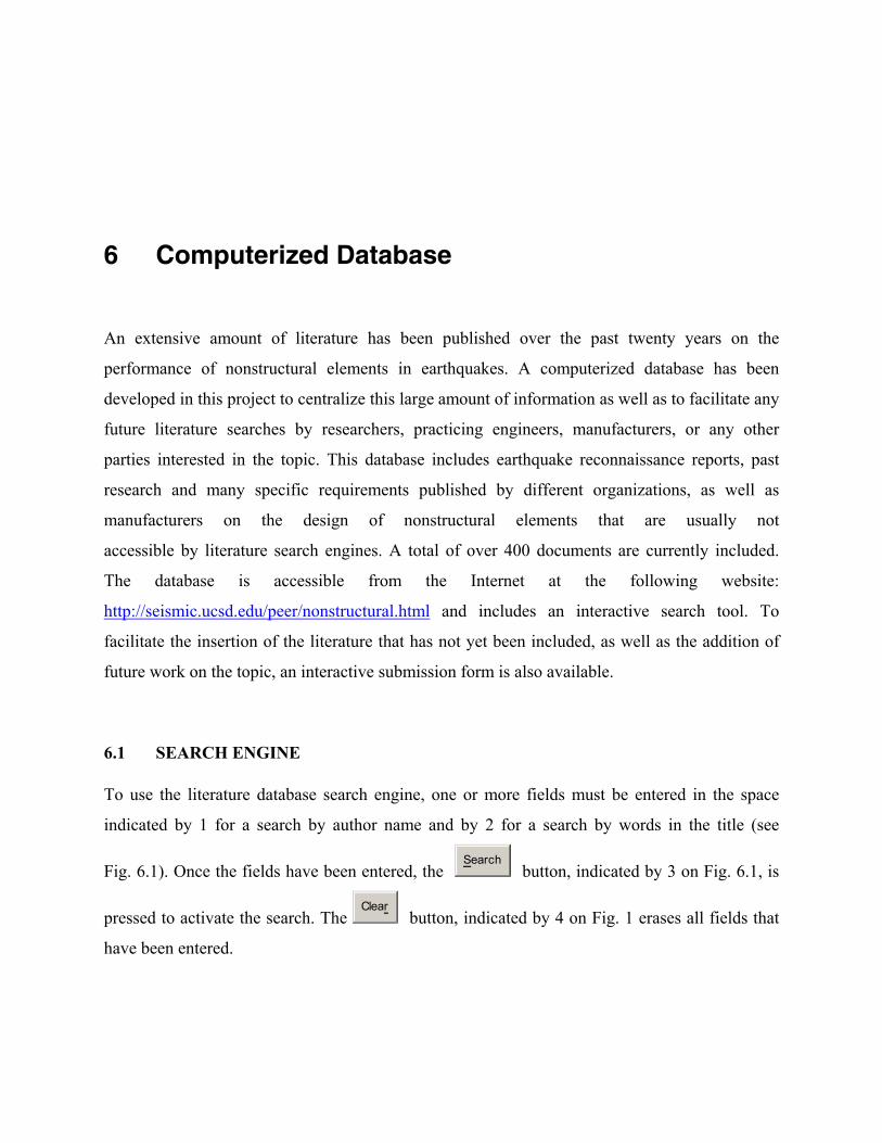
63
6 Computerized Database
An extensive amount of literature has been published over the past twenty years on the
performance of nonstructural elements in earthquakes. A computerized database has been
developed in this project to centralize this large amount of information as well as to facilitate any
future literature searches by researchers, practicing engineers, manufacturers, or any other
parties interested in the topic. This database includes earthquake reconnaissance reports, past
research and many specific requirements published by different organizations, as well as
manufacturers on the design of nonstructural elements that are usually not
accessible by literature search engines. A total of over 400 documents are currently included.
The database is accessible from the Internet at the following website:
http://seismic.ucsd.edu/peer/nonstructural.html and includes an interactive search tool. To
facilitate the insertion of the literature that has not yet been included, as well as the addition of
future work on the topic, an interactive submission form is also available.
6.1 SEARCH ENGINE
To use the literature database search engine, one or more fields must be entered in the space
indicated by 1 for a search by author name and by 2 for a search by words in the title (see
Fig. 6.1). Once the fields have been entered, the Search
button, indicated by 3 on Fig. 6.1, is
pressed to activate the search. The Clear
button, indicated by 4 on Fig. 1 erases all fields that
have been entered.
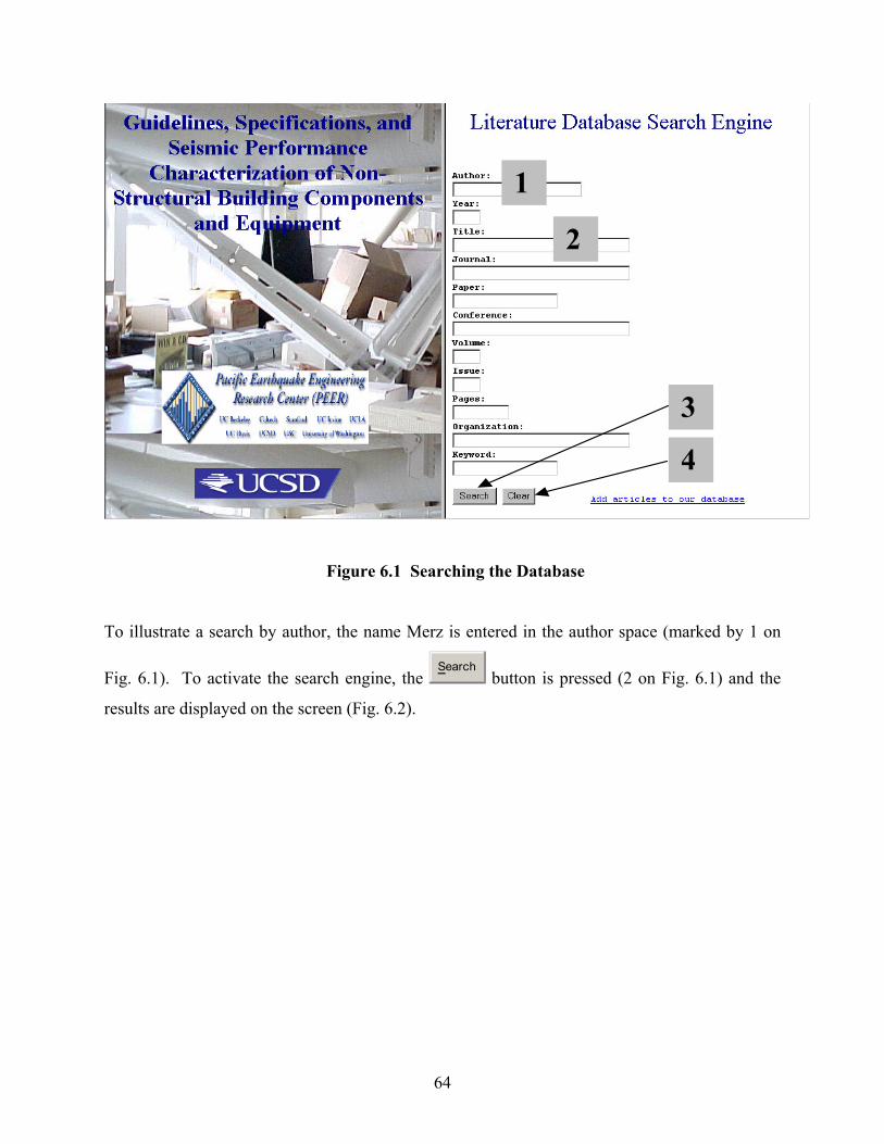
64
Figure 6.1 Searching the Database
To illustrate a search by author, the name Merz is entered in the author space (marked by 1 on
Fig. 6.1). To activate the search engine, the Search
button is pressed (2 on Fig. 6.1) and the
results are displayed on the screen (Fig. 6.2).
1
3
4
2
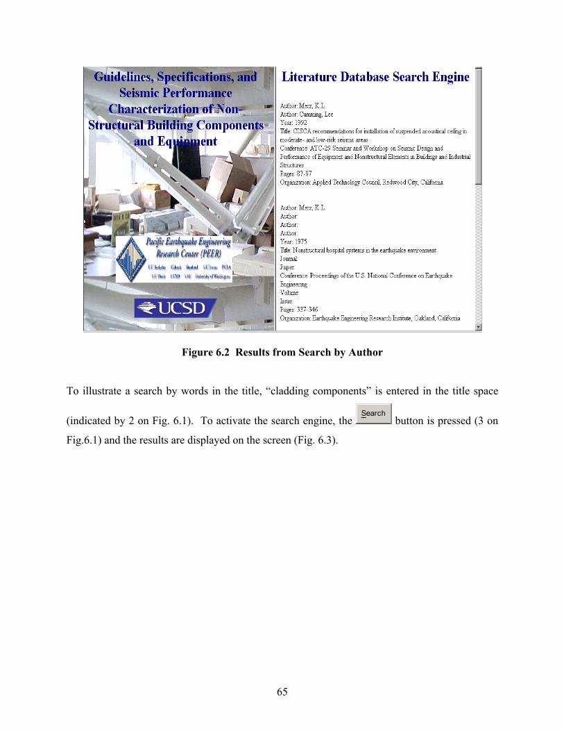
65
Figure 6.2 Results from Search by Author
To illustrate a search by words in the title, “cladding components” is entered in the title space
(indicated by 2 on Fig. 6.1). To activate the search engine, the Search
button is pressed (3 on
Fig.6.1) and the results are displayed on the screen (Fig. 6.3).
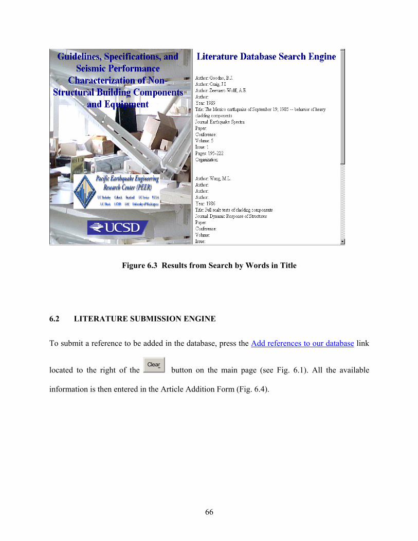
66
Figure 6.3 Results from Search by Words in Title
6.2 LITERATURE SUBMISSION ENGINE
To submit a reference to be added in the database, press the Add references to our database link
located to the right of the Clear
button on the main page (see Fig. 6.1). All the available
information is then entered in the Article Addition Form (Fig. 6.4).
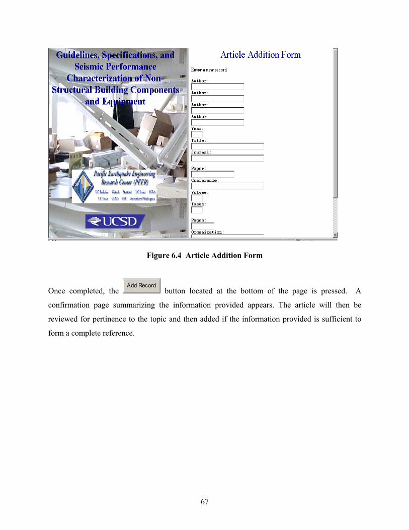
67
Figure 6.4 Article Addition Form
Once completed, the Add Record
button located at the bottom of the page is pressed. A
confirmation page summarizing the information provided appears. The article will then be
reviewed for pertinence to the topic and then added if the information provided is sufficient to
form a complete reference.
69
7 Summary of Gaps in Knowledge and Recommendations for the Development of a Rational Research Plan on Nonstructural Building Components
7.1 GENERAL RECOMMENDATIONS
7.1.1 Development of Efficient Data Collection Methods
The statistical summaries from past earthquakes on the damage to nonstructural building
components play a very important role in formulating code design/retrofit improvements.
However, there are problems associated with the collection of information. The most significant
problem is the lack of record of relevant engineering details associated with the failure of
nonstructural building components. This inadequate reporting of information, both following the
main shock and potential strong aftershocks, often makes it difficult to establish the real cause of
the failures. Non-engineering personnel, lacking the training required to assess damage and
identify modes of failure, usually do the task of collecting information related to the failure of
nonstructural building components.
There is an urgent need for the development of a post-earthquake field reconnaissance “tool kit”
for nonstructural components. This tool kit could take several forms and should include sets of
sample forms to efficiently collect information on the damage and failure of nonstructural
building components in the aftermath of an earthquake.
70
Furthermore, there is an urgent need to establish an overall data collection strategy. As stated by
Reitherman (1998), a significant effort is necessary to yield reliable and useful data. Elaborating
such a strategy would require an efficient distribution of the efforts between (1) questionnaires
for inexpensive widespread data collection by non-qualified personnel and (2) guidelines for
collecting higher quality and consequently more expensive information by qualified personnel. A
subsequent effort to coordinate both sets of data and to correlate them to ground shaking
intensity and structural performance is also needed. This strategy must be pre-established and
“ready to go” because a significant portion of the damage to nonstructural elements is cleaned up
and rapidly repaired following an earthquake to allow occupants to resume their activities. The
information must be gathered within the first three days following an earthquake. A
comprehensive data collection effort may require as much as 12 to 24 months after the
earthquake to be completed, and entails significant interaction among all concerned parties,
including research-oriented organizations and universities, practitioners, industry groups,
standards organizations, political organizations, as well as government agencies.
7.1.2 Development of Post-Earthquake Nonstructural Inspection Procedures
Based mainly on observations from the Northridge earthquake, there has been an inconsistency
in the application of post-earthquake safety criteria to nonstructural components compared to the
application of similar safety criteria to structural components and systems. For example, at least
75 hospitals tagged green following the Northridge earthquake suffered sufficient nonstructural
damage to prevent operation of many services and closure of certain areas of the buildings
(OSHPD 1994). Serious consequences could have resulted had a strong aftershock hit these
facilities and caused further damage to nonstructural components.
Specific procedures for the post-earthquake safety inspection of nonstructural components need
to be developed. These procedures will need to be harmonized with the current structural safety
evaluation procedures.
71
7.1.3 Development of Seismic Analysis Methods for Nonstructural Components
The determination of seismic design forces on nonstructural components has become more
complicated due to the variety of procedures available, the various assumptions that these
procedures are based on, and the difficulty of classifying the variety of components in a rational
way. The complexity of many of these procedures, however, has precluded their utilization in
building code provisions. Furthermore, current procedures are based mainly on judgment and
intuition rather than engineering research results. One of the main problems associated with the
evaluation of seismic design forces is the difficulty in classifying the various types of
nonstructural systems and components. Historically, nonstructural components have been
classified based on their usage characteristics. Another classification of nonstructural
components based perhaps on their seismic response characteristics needs to be elaborated.
Another urgent need is the evaluation of current seismic design procedures and the development
of improved yet, sufficiently simple, methods (static and dynamic) for determining realistic
seismic design forces and drifts on floor-mounted nonstructural components. These methods
need to address the following aspects that have not been fully considered to date:
• The influence of damping properties of structural and nonstructural components
• The influence of structural and nonstructural components non-linearity
• The influence of structural torsion
• The distribution of floor accelerations along the building height
• The seismic response of base-isolated or passively controlled secondary systems
• The interaction between structural and nonstructural elements and interconnected
nonstructural elements
Data recorded from instrumented buildings during recent earthquakes in the United States and
Japan should be used to assess the validity and effectiveness of simplified methods of analysis
72
included in current design methods. Further instrumentation of buildings to provide information
specific to the response of nonstructural components during future earthquakes is also needed.
7.1.4 Development of Experimental Seismic Qualification Procedures for Nonstructural Components
An extensive experimental program is urgently needed to complement the substantial amount of
ongoing analytical studies on the seismic behavior of nonstructural components. The
development of static and dynamic (shake table) test protocols is required to characterize the
physical properties of nonstructural components and qualify both their structural and functional
performances during seismic events.
7.1.5 Application of Performance-Based Earthquake Engineering to Nonstructural Components
With the development of performance-based earthquake engineering, harmonization of the
performance levels between structural and nonstructural components is necessary. Even if the
structural components of a building reach an immediate-occupancy performance level during a
seismic event, equipment failure inside the building can lower the performance level of the entire
building system. This reduction in performance caused by the vulnerability of nonstructural
components has been particularly evident in several buildings during the recent 2001 Nisqually
earthquake in the Seattle-Tacoma area (Filiatrault et al. 2001), as already noted in Chapter 1.
As a result of improved building codes, structural systems are expected to perform better in a
seismic event. Increasing the strength of buildings results in structures responding more in the
elastic range, thereby increasing the floor acceleration levels. Elaborate detailing of structural
systems to provide a stable post-yielding behavior, without degradation, also contributes to
increasing the effective accelerations soliciting the nonstructural components, as the initial
stiffness is recovered at every cycle. Furthermore, as illustrated by the 2001 Nisqually
earthquake, the response of the structural system to lower seismic events may be linear while
significant accelerations are experienced in the building. This underscores the importance of
linking design requirements for nonstructural elements to the response of the structural system
73
under various ground shaking intensity levels. Also, a sensitivity study on the effect of the main
structural system, i.e., stiff wall systems versus flexible frame systems, on the expected damage
to both acceleration and displacement sensitive nonstructural elements should be available to
structural engineers in order to fully assess the cost-benefit implications of design decisions.
Holmes (1984) suggested an approach that required identifying the structural response
parameters and their relationship to nonstructural damage. Various building deformation modes
such as shear-type distortions typical of framed structures, bending-type distortions typical of
wall structures, as well as soft-story mechanisms are considered.
Methods that have been developed for the application of performance-based earthquake
engineering should be considered and tailored to nonstructural components. These methods
should make use of the analysis tools to be developed as suggested in 7.1.3, the experimental
data obtained from the seismic qualification protocol to be developed as proposed in 7.1.4, and
should also include cost-benefit decision tools in order to select appropriate performance levels
for nonstructural components. These performance levels for nonstructural components also need
need to be harmonized with the structural performance levels.
Physical installation methods consistent with these performance levels need to be developed.
These installation methods must also consider the interaction of different nonstructural
components when installed side by side. In many instances, it has been observed that the
performance of adjacent nonstructural components has been lowered because of a lack of
coordination in installation procedures causing the total system to function at a lower
performance level than intended (Reitherman and Sabol 1995).
7.1.6 Comprehensive Assessment and Design of Nonstructural Elements
There is an urgent need to create a comprehensive framework for the seismic assessment and
design of nonstructural elements. An important amount of specific information is available
through field reconnaissance reports, published research, design codes, and specific
74
requirements, but very little has been done to incorporate this into a complete procedure that
fully accounts for the complex interaction between the main structural system and the
nonstructural elements. The poor performance of nonstructural elements in past earthquakes
triggered changes to code requirements resulting in reassessment of design force requirements or
detailing to provide displacement capacity. Although these enhanced requirements led to better
performance of the specific elements considered, a general methodology is needed that is
consistent with the current performance-based seismic design philosophy. The performance of
buildings can no longer be assessed independently of the performance of the nonstructural
elements and vice versa. It is therefore sensible to define both the structural and nonstructural
elements early in the design phase, and to explicitly consider them jointly during the subsequent
design iteration process.
Figure 7.1 illustrates a possible comprehensive framework for the seismic assessment and design
of nonstructural elements. Once a performance level is set for a given ground motion intensity,
the first task in this procedure is to clearly identify all nonstructural elements that are considered
in the design process. A clear evaluation of the load path from the center of mass of each
nonstructural element to the main structure must be determined, and all the connectors allowing
this load path must be identified and characterized. The connection points of each nonstructural
element to the main structure and to other nonstructural elements must be identified. This
process allows to locate the points where the demand on the nonstructural elements must be
evaluated. Among these elements, those affecting the response of the main structural system
must be identified and their stiffness, strength and damping characteristics must be included in
the structural response of the main system.
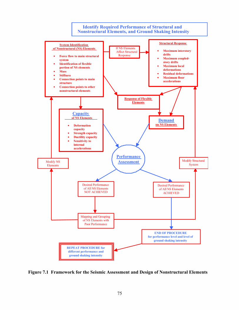
75
Figure 7.1 Framework for the Seismic Assessment and Design of Nonstructural Elements
System Identification of Nonstructural (NS) Elements
• Forc e flow to main structural system
• Identification of flexible portion of NS elements
• Mass • Stiffness • Connection points to main
structure • Connection points to other
nonstructural elements Response of Flexible
Elements
If NS Elements Affect Structural
Response
Structural Response
• Maximum interstory drifts
• Maximum coupled- story drifts
• Maximum local deformations
• Residual deformations • Maximum floor
accelerations
Capacity of NS Elements
• Deformation
capacity • Strength capacity • Ductility capacity • S ensitivity to
internal accelerations
Demand on NS Elements
Performance Assessment
Desired Performance of All NS Elements
ACHIEVED
END OF PROCEDURE for performance level and level of
ground shaking intensity
Modify Structural System
Modify NS Elements
Desired Performance of All NS Elements NOT ACHIEVED
Mapping and Grouping of NS Elements with
Po or Performance
Identify Required Performance of Structural and Nonstructural Elements, and Ground Shaking Intensity
REPEAT PROCEDURE for different performance and ground shaking intensity
76
The structural response must then be evaluated based on a required degree of modeling
sophistication. In many cases, not considering the nonlinear characteristics of the structure will
lead to unrealistic estimates of the structural response. The structural response must provide the
following information:
• Maximum interstory drift
• Maximum coupled-story drifts (the required coupled drifts are defined by the boundary
conditions or connection points of the nonstructural elements to the main structure, for
example a piping system connected at the first and third floors)
• Maximum local deformations. In many cases, especially for multi-span frames with
different span lengths, the local deformation at the location of plastic hinges may be
significantly larger than the average interstory drift due to geometric considerations.
• Residual deformations
• Maximum floor accelerations
This list of response indices influencing the performance of nonstructural elements can be
updated as more particular nonstructural elements are identified. At this point, the performance
level of the main structural system is verified. Although this phase is not explicitly shown in
Figure 7.1 for sake of clarity, it nevertheless remains a very important stage of the performance
assessment framework. The structural system is modified until the required performance level is
reached.
These structural responses are then fed as input to the dynamic evaluation of the flexible portions
of the nonstructural elements. The results from this dynamic evaluation, which is also carried out
at the required degree of sophistication, along with results coming directly from the response of
the main structure, define the demand side of the performance assessment process.
Based on the nonstructural system identification process, and on the characteristics of each
nonstructural element, the capacity of each nonstructural element is established. This process
consists of coupling different values of an input quantity to the performance of the nonstructural
77
element. This process is similar to the performance-based curve of a structural system, where the
force-deflection relationships define different levels of performance. This must be carried out,
when deemed applicable, to the following input quantities:
• For each rigidly attached nonstructural element, and for the rigidly attached portions of
flexible nonstructural elements, as defined earlier, the strength and ductility
characteristics of connectors must be identified.
• For each nonstructural element attached to more than one point to the main structure or to
other nonstructural elements, a thorough survey of the displacement capacity between
these attachment points must also be carried out.
• For each flexible portion of nonstructural elements, the force deflection characteristics
must be assessed and coupled with performance levels.
• For internally sensitive equipment, the performance for various acceleration levels must
be determined.
The determination of the capacity can be as simple as acceptable or defined by more complex
functions defining different levels of performance. The performance assessment process then
becomes the coupling between the demand and the capacity, as previously defined. Each
component is first assessed individually, and then all performance levels are summed up to
determine a global performance. The nonstructural elements that did not perform to the required
level are then identified and fed as input to the mapping and grouping process. This process is
very important to determine if there is a location in the building where the nonstructural
elements are performing poorly, and to identify families of nonstructural elements performing
poorly. At this point the designer must loop over the design process. Based on the mapping and
grouping information, a design decision must be made. The first possibility is to intervene at the
level of the nonstructural element. A choice of changing either the component itself, modifying
its boundary conditions, or introducing a new detail to the same system is possible. Another
possibility can be to modify the structural system to reduce the demand side of the performance
78
assessment. Hybrid solutions combining changes to both the nonstructural elements and to the
structural system can also be considered.
This process is repeated until the required performance levels of both the structural system and
all nonstructural elements are achieved. The process is also repeated for different couples of
performance levels and ground shaking intensity.
It must be noted that a series of indications on the global characteristics of structures
incorporating different lateral load-resisting systems would be useful beforehand as a guideline
to designers. Guidelines such as inherently high drift or floor accelerations would allow choosing
either the nonstructural system itself or initially modifying a detail to account for this
characteristic structural response. It may even be assessed in the early stages of the design
process that the structural system should be modified, either by changing the lateral load-
resisting system or by isolating or bracing an existing system.
Also, considering that the performance of nonstructural elements in a building is usually not a
function of building height, structural systems whose response quantities are constant with
height are likely to lead to better overall performance of the nonstructural elements.
7.2 RECOMMENDATIONS FOR BUILDING CONTENTS
Past earthquakes have shown that damage to building contents is not correlated with the intensity
of the shaking as usually measured. For example, many buildings located in the most intensely
shaken areas affected by the 1994 Northridge earthquake suffered surprisingly low contents
damage. Analytical studies on the effect of horizontal and vertical accelerations on freestanding
content items could explain this phenomenon and should be undertaken.
79
Library shelving as well as storage rack systems have proven to be very vulnerable to ground
shaking. Further work is needed to mitigate damage, which typically comes in the form of
complete collapse, partial failure without collapse and/or content toppling. Although increasing
the strength of these systems is necessary to prevent full collapse, further investigations on the
correlation between rack response and material toppling is needed. Performance of these systems
must be defined on a dual level, to encompass both the structural performance of the shelving
systems as well as toppling of contents. As shown in recent full-scale shake table tests on
warehouse storage racks (Filiatrault and Christopoulos 2001), these systems can typically
undergo large inelastic displacements in the in-plane direction without compromising their
vertical load-carrying capacity and while introducing a considerable amount of viscous damping.
Detailing these systems to increase their ductility is likely to increase their global performance
by limiting the accelerations on the contents. In the out-of-plane direction, where accelerations
are expected to be larger as a result of the stiffer structural system, further practical
recommendations on restraining contents are needed. Further research is also needed to define
the critical loading combinations for different failure modes, especially for the shelving system
anchor uplift.
7.3 RECOMMENDATIONS FOR BUILDING SERVICE EQUIPMENT
7.3.1 Recommendations for Elevator and Escalator Systems
The practical implementation of seismic and displacement switches in elevator systems is not
easy (Suarez and Singh 2000). One of the main problems is that these switches can be activated
by non-seismic disturbances such as vibrating machinery, nearby traffic, or nearby construction
work. The development of a new generation of seismic sensors for elevator systems is an area of
active research that draws in researchers operating outside traditional earthquake engineering
disciplines. Shake table testing of seismic and displacement elevator switches commercially
available in the United States also needs to be undertaken.
Furthermore, results of the few dynamic analyses performed on elevator systems seem to
indicate that the seismic design procedures included in the ASME A17.1 Code (American
80
Society of Mechanical Engineering 1996) may not be conservative for all cases. The
development of rational analytical/numerical models to evaluate the demand and capacity of
elevator systems is a worthwhile undertaking within the general framework of performance-
based earthquake engineering.
7.3.2 Recommendations for Mechanical, Electrical, and Appliance Equipment
The performance of mechanical and electrical systems in past earthquakes has been good for
rigidly mounted systems provided that anchors were designed for code-level forces. However,
some of the anchors that were well sized to carry these seismic forces failed prematurely as a
result of anchor pullout. Better detailing of the connection between the anchor and the main
structure (typically concrete slabs) is needed to insure that the forces are transmitted to the main
structural system.
On the other hand, the poor performance of isolated equipment demonstrated the need to fully
reassess the seismic performance of systems mounted on springs or rubber. A coordinated effort
between the structural and mechanical engineering professions is needed to insure adequate
performance of these vibrating systems under both low-amplitude, higher-frequency mechanical
vibrations and higher-amplitude vibrations induced by seismic loading of the main structure. A
further effort to realistically assess the amplification factors of existing equipment mounted on
these isolation systems is also needed to guide strengthening work on existing equipment.
For water heaters, it is suggested that the restraints be engineered to assure adequate protection
of these systems. Shut-off valves, triggered by ground shaking, have also been found to
effectively reduce the risk of fire caused by the failure of water heaters, but they do not prevent
damage to the water heater.
81
7.3.3 Recommendations for Ductwork and Piping Systems
The 1994 Northridge earthquake demonstrated that the common belief that small-diameter
piping (less than 1 in.) needs no bracing may not be true. The evaluation of current bracing
requirements for piping systems, supported by systematic analytical and experimental studies,
would be beneficial in order to provide adequate bracing requirements for the whole range of
piping systems.
For fire sprinkler systems, the elaboration of flexible details at the connection of the main water
branch and the smaller water branches located within the suspended ceiling and/or the
uncoupling of the sprinkler system from the suspended ceiling would greatly enhance the
performance of these systems during earthquakes.
7.4 RECOMMENDATIONS FOR BUILDING UTILIZATION EQUIPMENT
7.4.1 Recommendations for Computer Equipment
Computer equipment is primarily susceptible to toppling or sliding during earthquakes, but can
also be affected by interstory displacements of the main structure or of the raised floors.
Techniques for restraining such equipment are available and have proved effective in past
earthquakes. However, computer equipment is also susceptible to internal damage. As effective
restraining strategies are implemented on computer equipment, the internal accelerations are
likely to increase, and can cause failure of the sensitive equipment contained within. A
coordination effort is necessary between structural and computer engineers to assure that the
seismic protection is not internally detrimental to the system. A better understanding of floor
accelerations as noted in Section 7.1.3, as well as proper communication of this information to
computer engineers would greatly reduce the risk of failure of computer systems during
earthquakes.
82
7.5 RECOMMENDATIONS FOR INTERIOR ARCHITECTURAL COMPONENTS
7.5.1 Recommendations for Ceiling Systems
Past earthquakes demonstrated that the performance of suspended ceiling systems was greatly
impaired by the interaction between the different structural and nonstructural interconnected
elements. Further research is needed to define recommendations on either achieving deformation
compatibility between the components or uncoupling these systems and allowing them to move
independently. Furthermore, the effect of the spacing between the ceiling and the underside of
the above floor on the amplification of the ceiling response should be investigated. The increased
stiffness resulting from a reduced spacing is likely to reduce the maximum deformations of the
system and therefore mitigate the problem of deformation compatibility with other systems.
7.6 RECOMMENDATIONS FOR NONSTRUCTURAL EXTERIOR CONSTRUCTION
7.6.1 Recommendations for Exterior Veneers
Although the beneficial effect provided by the wall finish materials was very pronounced in the
wood-frame house tested by Fischer et al. (2001), it is unclear if this effect would also occur in
larger wood-frame structures with more complicated geometry. Nevertheless, the results of that
study have provided a motivation to examine further the effectiveness of wall finish materials as
potential structural components of lateral load-resisting systems of wood-frame structures.
Several issues need to be addressed before these materials can be effectively considered in
design. For example, the method of attachment of stucco to the wood framing should be
researched in order to evaluate current practices, and possibly develop improved attachment
methods that could mobilize the lateral stiffness and strength of stucco for the sequence of
earthquakes that a wood-frame building could experience during its lifespan.
7.6.2 Recommendations for Glass Doors, Windows, and Glazing
The performance of glass doors, windows and glazing during earthquakes is highly dependent on
the deformation capacity provided to the brittle material with respect to its supporting frame.
More elaborate specifications are needed to fully address this issue, for all types of glass and

83
different pane sizes. Furthermore, in the framework of performance-based earthquake
engineering, an effort to better correlate the expected interstory distortion of the main structural
system to the displacement capacity of the glass systems is needed.
85
REFERENCES
American Society of Civil Engineers (ASCE). 1995. “Minimum Design Loads for Buildings and
Other Structures,” ASCE 7-95, American Society of Civil Engineers.
American Society of Mechanical Engineers (ASME). 1996. “Safety Code for Elevators and
Escalators,” ASME A17.1, American Society of Mechanical Engineers, New York NY.
Amick, H., and Bayat, A., 1998. “Seismic Isolation of Semi Conductor Production Facilities”,
Proceedings of the Seminar on Seismic Design, Retrofit, and Performance of
Nonstructural Components, ATC-29-1, San Francisco, CA, pp. 297-312.
Amin, M., Hall, W.J., Newmark, N.M., and Kassawara, R.P. 1971. “Earthquake Response of
Multiply Connected Light Secondary Systems by Spectrum Methods,” Proceedings of the
1st National Congress on Pressure Vessels and Piping, American Society of Mechanical
Engineers, New York, NY, 103-129.
Applied Technology Council (ATC). 1992a. “Procedures for Post-disaster Safety Evaluation of
Postal Service Facilities (Interim)”, ATC 26-2, Produced by ATC for USPS use. Applied
Technology Council, Redwood City, California, 221 p., (Available only to Government
Agencies).
Applied Technology Council (ATC). 1992b. “U.S. Postal Service Field Manual: Post-earthquake
Safety Evaluation of Buildings (Interim)”, ATC 26-3, Produced by ATC for USPS use.
Applied Technology Council, Redwood City, California, 133 p., (Available only to
Government Agencies).
Applied Technology Council (ATC). 1997a. “NEHRP Guidelines for the Seismic Rehabilitation
of Buildings,” developed by the Building Seismic Safety Council for the Federal Emergency
Management Agency (FEMA 273), Washington, DC.
Applied Technology Council (ATC). 1997b. “NEHRP Commentary on the Guidelines for the
Seismic Rehabilitation of Buildings,” developed by the Building Seismic Safety Council for
the Federal Emergency Management Agency (FEMA 274), Washington, DC.
Asfura, A., and Der Kiureghian, A. 1986. “Floor Response Spectrum Method for Seismic
Analysis of Multiply Supported Secondary Systems, “ Earthquake Engineering and
Structural Dynamics, 14(2), 245-265.
86
Atalik, T.S. 1978. “An Alternative Definition of Instructure Response Spectra,” Earthquake
Engineering and Structural Dynamics, 6(1), 71-78.
Ayres, J.M., and Sun, T.Y. 1973. “Nonstructural Damage,” in The San Fernando, California
Earthquake of February 9, 1971. US Department of Commerce, National Ocean and
Atmospheric Administration, 1(B), 736-742.
Ayres, J.M., Sun, T.Y., and Brown, F.R. 1973. “Nonstructural Damage to Buildings,” in The
Great Alaska Earthquake of 1964: Engineering, Division of Earth Sciences, National
Research Council, National Academy of Sciences, Washington, DC, 346-456.
Ayres, J.M., & Ezer and Hillman Biddison & Loevenguth. 1996. “Northridge Earthquake
Hospital Water Damage Study”, Office of Statewide Health Planning and Development,
Sacramento, CA.
Ayres, J.M., and Philips, R. 1997. “Water Damage in Hospital Resulting from the Northridge
Earthquake,” Proceedings of the NEHRP Conference and Workshop on Research on the
Northridge, California Earthquake of January 17, 1994, Consortium Universities for
Research in Earthquake Engineering (CUREE), Richmond, California, Vol. III-312-313.
Bachman, R.E. 1998. “Building Code Seismic Design Provisions for Nonstructural
Components,” Proceedings of the Seminar on Seismic Design, Retrofit, and Performance
of Nonstructural Components, ATC-29-1, San Francisco, CA, 7-14.
Bachman, R.E., and Drake, R.M. 1998. “Design Force Provisions for Nonstructural Elements
and Model Codes,” Proceedings of the 6th U.S. National Conference on Earthquake
Engineering, Seattle, Washington, on CD-ROM.
BAREPP, 1990. “Earthquake Preparedness Training for Businesses”, Bay Area Regional
Earthquake Preparedness Project, San Francisco, California.
BCJ 1997. “Architectural Nonstructural Seismic Design Guide”, Building Center of Japan (in
Japanese).
Behr, R.A., Belarbi, A., and Culp, J.H. 1995. “Dynamic Racking Tests of Curtain Wall Glass
Elements with In-Plane and Out-of-Plane Motions,” Earthquake Engineering and
Structural Dynamics, 24(1), 1-14.
Behr, R.A., and Worrell, C.L., 1998. “Limit States for Architectural Glass Under Simulated
Seismic Loadings”, Proceedings of the Seminar on Seismic Design, Retrofit, and
Performance of Nonstructural Components, ATC-29-1, San Francisco, CA, 229-240.
87
Bellcore, 1995. “Network Equipment-Building System (NEBS) Requirements: Physical
Protection”, Generic Requirements, GR-63-CORE.
Biggs, J.M., and Roesset, J.M. 1970.“Seismic Analysis of Equipment Mounted on a Massive
Structure,” Seismic Design for Nuclear Power Plant, R.J. Hansen, Editor, MIT Press,
Cambridge, Mass., 319-343.
Bouwkamp, J.G., and Meehan, J.F. 1960. “Drift Limitations Imposed by Glass,” Proceedings of
the 2nd World Conference on Earthquake Engineering, Tokyo and Kyoto, Japan, Vol. III,
1763-1778.
Building Seismic Safety Council (BSSC). 1992. “NEHRP Handbook of Techniques for the
Seismic Rehabilitation of Existing Buildings”, Prepared by the Building Seismic
Safety Council for the Federal Emergency Management Agency (FEMA-172),
Washington, DC, 197 p.
Burdisso, R.A., and Singh, M.P. 1987. “Seismic Analysis of Multiply Supported Secondary
Systems with Dynamic Interaction Effects,” Earthquake Engineering and Structural
Dynamics, 15(8), 1005-1022.
Chen, Y., and Soong, T.T. 1988. “State-of-the-art-Review: Seismic Response of Secondary
Systems,” Engineering Structures, 10(4), 218-228.
Chiba, T., Kobayashi, H., Ogawa, N., Minowa, C., and Shibata, H. 1992. “An Experimental
Study on the Stability of Cracked Piping System Supported by a Nonlinear Support,”
Proceedings of the 10th World Conference on Earthquake Engineering, Vol. 5, A.A.
Balkema, Rotterdam, The Netherlands, 2707-2712.
Cohen, J.M. 1995. “Seismic performance of Cladding: Responsibility Revisited,” Journal of
Performance of Constructed Facilities, ASCE, 9(4), 254-270.
Comerio, M. 2000. “The Economic Benefits of a Disaster Resistant University: Earthquake Loss
Estimation for UC Berkeley,” Working Paper 2000-02, Institute of Urban and Regional
Development, University of California, Berkeley, CA.
Comerio, M., Stallmeyer, J.C., Holmes, W., Adamson, D.L., and Lau, S. 2001. “Nonstructural
Loss Estimation: The UC Berkeley Case Study,” PEER Report in Progress, Pacific
Earthquake Engineering Research Center, Berkeley, CA.
Craig, J.I., and Goodno, B.J. 1981. “Response Measurements for Glass Cladding Panels,”
Journal of the Structural Division, ASCE, 107(11), 2199-2214.
88
Der Kiureghian, A., Sackman, J.L., and Nour-Omid, B. 1983. “Dynamics Analysis of Light
Equipment in Structures: Response to Stochastic Input,” Journal of Engineering
Mechanics, ASCE, 109(1), 90-110.
Dewell, D., and Willis, B. 1925. “Earthquake Damage to Buildings,” Bulletin of the
Seismological Society of America, 15(4).
Ding, D., and Arnold, C., coordinators, 1990. “Architecture, Building Contents, and Building
Systems,” Chapter 9 in Supplement to Volume 6: Loma Prieta Earthquake
Reconnaissance Report, Earthquake Spectra, 339-377.
Drake, R.M., and Braganolo, L.J. 2000. “Model Code Design Force Provisions for Elements of
Structures and Nonstructural Components,” Earthquake Spectra, 16(1), 115-125.
DSA 1994. “Northridge Earthquake – Public School Buildings. Final Report,” Division of the
State Architect, Sacramento, CA.
Elsesser, E., 1984. “Life Hazards Created by Nonstructural Elements”, Nonstructural Issues of
Seismic Design and Construction”, Publication No. 84-04, Earthquake Engineering
Research Institute, pp.27-36.
EPRI 1990. “Procedure for Seismic Evaluation and Design of Small Bore Piping”, EPRI NP-
6628, Electric Power Research Institute.
EQE. 1995. “Summary Report – The January 17, 1995 Kobe Earthquake,” EQE International,
San Francisco, CA.
Filiatrault, A., 1991. “Seismic Evaluation of Modular Office Furniture System,” Earthquake
Spectra, 7(4), 529-541.
Filiatrault, A., Uang, C-M., Folz, B., Christopoulos, C., and Gatto, K. 2001. “Reconnaissance
Report of the February 28, 2001 Nisqually (Seattle-Olympia) Earthquake,” Structural
Systems Research Project Report No. SSRP-2000/15, Department of Structural
Engineering, University of California, San Diego, La Jolla, CA, 62 p.
Filiatrault, A., and Christopoulos, C. 2001. “Shake Table Testing of Home Depot Shelving
System,” Structural Systems Research Project Test Report No. TR-2001/03, Department
of Structural Engineering, University of California, San Diego, La Jolla, CA, 110 p.
Finley, J., Anderson, D., and Kwan, L. 1996. “Report on the Northridge Earthquake Impacts to
Hospital Elevators,” Contract No. 94-5122, Office of Statewide Health Planning and
Development, Sacramento, CA.
89
Fischer, D., Filiatrault, A., Folz, B., Uang, C-M., and Seible, F. 2001. “Shake Table Tests of a
Two-Story Woodframe House”, Structural Systems Research Project Report No. SSRP-
2000/15, Department of Structural Engineering, University of California, San Diego, La
Jolla, CA, 58 p.
Fleming, R.P. 1998. “Analysis of Fire Sprinkler System Performance in the Northridge
Earthquake,” Report No. NIST-GCR-98-636, U.S. Department of Commerce, Building
and Fire Research Laboratory, National Institute of Standards and Technology,
Gaithersburg, MD, 61 p.
Freeman, S.A., and Kehoe, B. 1997. “Review of Proposed Design Accelerations for
Nonstructural Elements,” Proceedings of the 4th Conference on Tall Buildings in Seismic
Regions,” Los Angeles Tall Buildings Structural Design Council and Council on Tall
Buildings and Urban Habitat,” Los Angeles, CA.
Freeman, S.A. 1977. “Racking Tests of High-Rise Building Partitions”, Journal of the Structural
Division, ASCE, 103(ST8), 1673-1685.
Freeman, S.A. 1998. “Design Criteria for Nonstructural Components Based on Tri-Services
Manuals”, Proceedings of the Seminar on Seismic Design, Retrofit, and Performance of
Nonstructural Components, ATC-29-1, San Francisco, CA, 7-14.
Fukuda, T. 1990. “Earthquake Resistive Elevators,” in Elevator World Educational Package and
Reference Library, 3, VI.3-VI.5.
Gates, W.E., and McGavin, G. 1998. “Lessons Learned from the 1994 Northridge Earthquake on
the Vulnerability of Nonstructural Systems,” Proceedings of the Seminar on Seismic
Design, Retrofit, and Performance of Nonstructural Components, ATC 29-1, San
Francisco, CA, 93-106.
Goodno, B., Craig, J., and Zeevaert-Wolf, A., 1989. “The Mexico Earthquake of September 19,
1985-Bahavior of Heavy Cladding Components,” Earthquake Spectra, 5(1), 195-222.
Goodno, B. 1994. “Survey and Preliminary Evaluation of Damage to Heavy Cladding Systems in
the January 17, 1994, Northridge Earthquake,” School of Civil Engineering, Georgia
Institute of Technology, Atlanta, GA.
Gupta, A.K. 1984. “Seismic Response of Multiply Connected MDOF Primary and MDOF
Secondary Systems,” Nuclear Engineering and Design, 81(3), 385-394.
90
Gupta, A.K., and Jaw, J.E. 1986. “A New Instructure Response Spectrum (IRS) Method for
Multiple Connected Secondary Systems with Coupling Effects,” Nuclear Engineering
and Design, 96(1), 63-80.
Harter, D. 1994. “Earthquake in Los Angeles. Glazing,” California Glass Association.
Hernried, A.G., and Sackman, J.L. 1984. “Response of Secondary Systems in Structures
Subjected to Transient Excitation,” Earthquake Engineering and Structural Dynamics,
12(6), 737-748.
Hillman, Biddison & Lovenguth. 1977. “Guidelines for Seismic Restraints of Kitchen
Equipment,” Sheet Metal Industry Fund of Los Angeles, Los Angeles, CA, 22 p.
Hiramatsu, K., Sato, Y., Agaki, H., and Tomita, S. 1988. “Seismic Response Observation of
Building Appendage,” Proceedings of the 9th World Conference on Earthquake
Engineering, Vol. 6, Tokyo, Japan, 237-242.
Holmes, W.T., 1984. “ Structural Relationships”, Nonstructural Issues of Seismic Design and
Construction”, Publication No. 84-04, Earthquake Engineering Research Institute, 37-47.
ICBO. 1994. “Uniform Building Code,” International Conference of Building Officials, Whittier,
CA.
ICBO. 1997. “Uniform Building Code,” International Conference of Building Officials, Whittier,
CA.
ICC. 2000. “International Building Code,” International Code Council, Whittier, California.
Igusa, T. 1990. “Response Characteristics of Inelastic 2-DOF Primary-Secondary Systems,”
Journal of Engineering Mechanics, ASCE, 116(5), 1160-1174.
Igusa, T., and Der Kiureghian, A. 1985a. “Generation of Floor Response Spectra Including
Oscillator-Structure Interaction,” Earthquake Engineering and Structural Dynamics,
13(5), 661-676.
Igusa, T., and Der Kiureghian, A. 1985b. “Dynamic Response of Multiply Supported Secondary
Systems,” Journal of Engineering Mechanics, ASCE, 111(1), 20-41.
Jin, M., and Astaneh-Asl, A. 1998. “Study of Seismic Resistance of Desktop Computers”,
Proceedings of the ATC-29 Seminar and Workshop on Seismic Design and Performance
of Equipment and Nonstructural Components in Buildings and Industrial Structures,
Applied Technology Council, Redwood City, CA, 379-392.
91
Johnson G.S., Sheppard, R.E., Quilici, M.D., Elder, S.J., and Scawthorn, C.R. 1999. “Seismic
Reliability Assessment of Critical Facilities: A Handbook, Supporting Documentation,
and Model Code Provisions,” Technical Report MCEER-99-0008, Multidisciplinary
Center for Earthquake Engineering Research, University at Buffalo, State University of
New York, Buffalo, NY, 384 pp.
Juhn, G., Manolis, G.D., and Reinhorn, A.M. 1990. “Experimental Analysis and Floor Response
Spectra for Secondary Systems in a Fixed-Base Frame,” Proceedings of the ATC-29
Seminar and Workshop on Seismic Design and Performance of Equipment and
Nonstructural Components in Buildings and Industrial Structures, Applied Technology
Council, Redwood City, CA, 277-292.
Kapur, K.K., and Shao, L.C. 1973. “Generation of Seismic Floor Response Spectra for
Equipment design,” Proceedings of the ASCE Conference Structural Design of Nuclear
Power Plants Facilities, Vol. 2, ASCE, New York, NY, 29-71.
Kawakatsu, T., Kitada, K., Takemori, T., Kuwabara, Y., and Okiwara, Y. 1979. “Floor Response
Spectra Considering Elasto-Plastic Behavior of Nuclear Facilities,” Transaction of the 5th
International Conference on Structural Mechanics in Reactor Technology,” North-
Holland Publishing Co., Amsterdam, the Netherlands, K9/4.
Kelly, J.M,. and Tsai, H.C. 1985. “Seismic Response of Light Internal Equipment in Base-
Isolated Structures,” Earthquake Engineering and Structural Dynamics, 13(6), 711-732.
King, A.B., and Lim, K.Y.S., 1991. “The Behavior of External Glazing Systems under Seismic
In-plane Racking”, Proceedings, Pacific Conference on Earthquake Engineering,
Auckland, New Zealand, 315-326.
Lagorio, H.J. 1990. “Earthquakes, An Architect’s Guide to Nonstructural Seismic Hazards,”
John Wiley & Sons, Inc., New York, NY.
Lam, F.C.F., Cherry, S., and Nathan, N.D., 1987. “Behavior of Equipment Isolation Systems
under Seismic Conditions”, Proceedings, 5th Canadian Conference on Earthquake
Engineering, Ottawa, Canada, 769-778.
Lee, M.C., and Penzien, J. 1983. “Stochastic Analysis of Structures and Piping Systems
Subjected to Stationary Multiple Support Excitations,” Earthquake Engineering and
Structural Dynamics, 11(1), 91-110.
92
Levy, R., Rutenberg, A., Segal, F., and Marianchik, E. 1996. “Analytical Evaluation of Elevator
Safety Code Seismic Provisions in Low-Rise Buildings”, Elevator World, XLIV(6), 110-
115.
Levy, R., Rutenberg, A., Magnus, P., Marianchik, E., and Segal, F. 2000. “Performance of
Elevator Systems in the 22 November 1995 Gulf of Eilat-Aqaba Earthquake”, Earthquake
Spectra, 16(3), 607-619.
Lin, J., and Mahin, S.A. 1985. “Seismic Response of Light Subsystems on Inelastic Structures,”
Journal of Structural Engineering, ASCE, 111(2), 400-417.
Marsantyo, R., Shimazu, T., Araki, H., Kabayama, K. and Kobayashi, M., 1998. “Experimental
Work on the Seismic Horizontal Force of Nonstructural Systems Mounted on the
Buildings”, Proceedings, 10th Earthquake Engineering Symposium, Vol. 2, Yokohama,
Japan, 2635-2640.
Marsantyo, R., Shimazu, T., and Araki, H. 2000. “Dynamic Response of Nonstructural Systems
Mounted on Floors of Buildings,” Proceedings of the 12th World Conference on
Earthquake Engineering, Paper No. 1872, Auckland, New Zealand, on CD-ROM.
Masami, J., and Astaneh-Asl, A., 1998. “Study of Seismic Resistance of Desktop Computers”,
Proceedings of the Seminar on Seismic Design, Retrofit, and Performance of
Nonstructural Components, ATC-29-1, San Francisco, CA, 379-392.
McGavin, G.L, Lai, J., and Ikkanda, S., 1998. “City of Los Angeles Proposed Ordinance
Changes for Suspended Ceiling Systems Prompted by the 1994 Northridge Earthquake”,
Proceedings of the Seminar on Seismic Design, Retrofit, and Performance of
Nonstructural Components, ATC-29-1, San Francisco, CA, 277-282.
McTiernan, W.E. 1994. “ Elevator Earthquake Damage – January 17, 1994,” Elevator, Tramway,
and Amusement Ride Unit of the California Division of Occupational Safety and Health,
San Francisco, CA.
Memari, A.M., Behr, R.A., and Kremer, P. 2000. “Toward Development of a Predictive Model
for Drift Limits in Architectural Glass Under Seismic Loadings”, Proceedings, 12th
World Conference on Earthquake Engineering, Paper No. 2140, Auckland, New Zealand,
on CD-ROM.
Meyer, J.D, Soong, T.T., and Hill, R.H. 1998. “Retrofit Seismic Mitigation of Mainframe
Computers and Associated Equipment: A Case Study”, Proceedings of the Seminar on
93
Seismic Design, Retrofit, and Performance of Non-Structural Components, ATC-29-1,
San Francisco, CA, 149-163.
MSS. 1993. “Pipe Hangers and Supports: Materials, Design and Manufacture,” Manufacturers
Standardization Society of the Valve and Fitting Industry, Vienna, VA.
Merz, K.L., and Eli, M.W. 1997. “The January17, 1994 Northridge Earthquake: Effects on
Electrical Power and Selected Industrial Facilities”. Proceedings of the NEHERP
Conference and Workshop on Research on the Northridge, California Earthquake of
January 17, 1994, 797-804.
Mroz, M.P., and Soong, T.T. 1997. “Fire Hazards and Mitigation Measures Associated with
Seismic Damage of Water Heaters”. Proceedings of the NEHRP Conference and
Workshop on Research on the Northridge, California Earthquake of January 17, 1994,
805-812.
Muscolino, G. 1990. “Dynamics Response of Multiply Connected Primary-Secondary Systems,”
Earthquake Engineering and Structural Dynamics, 19(2), 205-216.
Naeim, F., and Lobo, R. 1998. “Performance of Nonstructural Components During the January
17, 1994 Northridge Earthquake – Case Studies of Six Instrumented Multistory
Buildings”, Proceedings of the Seminar on Seismic Design, Retrofit, and Performance of
Nonstructural Components, ATC-29-1, San Francisco, CA, 107-119.
Nazarova, M.K. 1990. “Measured Full-Scale Investigations of Lifts Seismic Stability,”
Proceedings of the 9th European Conference on Earthquake Engineering, Vol. 6,
Moscow, Russia, 238-242.
Newmark, N.M. 1972. “Earthquake Response Analysis of Reactor Structures,” Nuclear
Engineering and Design, 20(2), 303-322.
Newmark, N.N., and Villaverde, T. 1980. “Computation of Seismic Response of Light
Attachments to Buildings,” Proceedings of the 7th World Conference on Earthquake
Engineering, Vol. 5, Istanbul, Turkey, 343-350.
NFPA. 1996. “Standard for the Installation of Sprinkler Systems,” NFPA-13, National Fire
Protection Association, Quincy, MASS.
Nims, D.K., and Kelly, J.M. 1990. “Experimental Study of Alternative Support Systems for the
Seismic Restraint of Piping,” Proceedings of the ATC-29 Seminar and Workshop on
Seismic Design and Performance of Equipment and Nonstructural Components in
94
Buildings and Industrial Structures, Applied Technology Council, Redwood City, CA,
393-404.
Nielsen, R.J., Schmeckpeper, E.R., and Crossler, R.W. 1998. “Seismic Retrofit of Precast
Concrete Connections”, Proceedings of the Seminar on Seismic Design, Retrofit, and
Performance of Non-Structural Components, ATC-29-1, San Francisco, CA, 201-214.
Nishizaka, R. Fukuwa, N., Yagi, S., and Tanaka, K., 1996. “A Study on the Effect of
Nonstructural Members on the Eigenproperties of 3 Story Prefabricated Steel Building
Based on Full-Scale Vibration Test”, Proceedings of the 11th World Conference on
Earthquake Engineering, Paper No. 1744, Acapulco, Mexico, on CD-ROM.
Nonstructural Issues of Seismic Design and Construction, 1984, Earthquake Engineering
Research Institute, Publication No. 84-04, Berkeley, CA.
Ohtani, K., Shibata, H., Watabe, M., Kawakami, M.S., and Ohno, T. 1992. “Seismic Proving
Tests for Nuclear Power Plant No. 1, Proceedings of the 10th World Conference on
Earthquake Engineering, Vol. 6, A.A. Balkema, Rotterdam, The Netherlands, 3603-3608.
Olson, R.A. 1987. “Data Processing Facilities: Guidelines for Earthquake Hazard Mitigation”,
California: Financial Insurance and Monetary Services Committee.
OSHPD, Office of Statewide Health Planning and Development. 1994. Draft Report to the
Building Safety Board on the Performance of Hospital Buildings in the Northridge
Earthquake of January 17, 1994, Sacramento, CA.
OSHPD, Office of Statewide Health Planning and Development. 1995. “Northridge Earthquake:
A Report to the Hospital Building Safety Board on the Performance of Hospitals”,
Technical Report, OSHPD, Facilities Development Division, Sacramento, CA.
Pantelides, C.P., and Behr, R.A. 1994. “Dynamic In-Plane Racking Tests of Curtain Wall
Elements,” Earthquake Engineering and Structural Dynamics, 23(2), 211-228.
Parise, G., Ferranti, F., and Colozza, R. 1995. “Tentative Criteria for the Design and Installation
of Electrical Power Systems Subject to Seismic Hazard,” Proceedings of the Technical
Conference on Industrial and Commercial Power Systems, IEEE, Piscataway, NJ, 93-98.
Peters, K.A., Schmitz, D., and Wagner, U. 1977. “Determination of Floor Response Spectra on
the Basis of the Response Spectrum Method,” Nuclear Engineering and Design, 44(2),
255-262.
95
Pernica, G., 1987. “Effect of Architectural Components on the Dynamic Properties of Long-
Span Floor Systems”, Canadian Journal of Civil Engineering, 14, 461-467.
Phan, L.T., and Taylor, A.W., 1996. “State of the Art Report on Seismic Design Requirements
for Nonstructural Building Components”, NISTIR 5857, National Institute of Standards
and Technology, Gaithersburg, MD, 67 p.
PWGSC 1995. “Guideline on Seismic Evaluation and Upgrading of Nonstructural Building
Components, Public Works and Government Services Canada, Ottawa, Ontario, 59 p.
Reitherman, R. 1985. “Reducing the Risks of Nonstructural Earthquake Damage: a Practical
Guide”, Second Edition, Bay Area Regional Earthquake Preparedness Project, Oakland,
CA., 86 p.
Reitherman, R. 1987. “A Guide to Establishing an Earthquake Protection Program for Local
Government Communications Facilities,” Pamphlet Produced for the San Mateo Area
Office of Emergency Services and the Bay Area Regional Earthquake Preparedness
Project, Oakland, CA.
Reitherman, R. 1994. “Nonstructural Components,” in John Hall, Editor, Northridge Earthquake:
January 17, 1994, Earthquake Engineering research Institute, Oakland, CA.
Reitherman, R., and Minor, S. 1989. “Technical Guidelines for Earthquake Protection of
Nonstructural Items in Communication Facilities,” Report Produced for the San Mateo
Area Office of Emergency Services and the Bay Area Regional Earthquake Preparedness,
Oakland, CA. 34 p.
Reitherman, R., and Sabol, T. 1995. “Nonstructural Damage,” in John Hall, Editor, Northridge
Earthquake of January 17, 1994 Reconnaissance Report, Supplement C to Earthquake
Spectra Vol. 11, Earthquake Engineering Research Institute, Oakland, CA.
Reitherman, R. 1997. “Contributions of Earthquake Reconnaissance to Improved Understanding
of the Seismic Behavior of Nonstructural Components,” Proceedings of Structures
Congress XV, Portland, OR, 645-651.
Reitherman, R. 1998. “The Need for Improvement in Post-Earthquake Investigations of the
Performance of Nonstructural Components”, Proceedings of the Seminar on Seismic
Design, Retrofit, and Performance of Nonstructural Components, ATC-29-1, San
Francisco, CA, 137-147.
96
Rihal, S.S., 1982. “Behavior of Nonstructural Building Partitions during Earthquakes”, VII
Symposium on Earthquake Engineering, Vol. 1, University of Roorkee, Roorkee, India,
267-277.
Rihal, S. 1988. “Earthquake Resistance and Behavior of Heavy Facades/Claddings &
Connections in Medium-Rise Steel-Framed Buildings,” Proceedings of the 9th World
Conference on Earthquake Engineering, Vol. 6, Tokyo-Kyoto, Japan, 207-212.
Rihal, S. 1992. “Correlation Between Recorded Building data and Nonstructural Damage During
the Loma Prieta Earthquake of October 19, 1989 – Selected Case Studies,” Proceedings
of the 10th World Conference on Earthquake Engineering, Vol. 1, A.A. Balkema,
Rotterdam, The Netherlands, 73-78.
Rihal, S. 1994. “Assessment of Seismic Safety Standards for Library Shelving,” Proceedings of
the 5th US National Conference on Earthquake Engineering, Chicago, IL, Vol. IV, 713-
724.
Rihal, S. 1998. “Performance and Behavior of Library Shelving and Storage Rack Systems
During the 1994 Northridge Earthquake”, Proceedings of the Seminar on Seismic Design,
Retrofit, and Performance of Nonstructural Components, ATC-29-1, San Francisco, CA,
121-135.
Rodriguez, M., Restrepo, J.I., and Carr, A.J., 2000. “Earthquake Resistant Precast Concrete
Buildings: Floor Accelerations in Buildings”, Research Report 2000-6, Department of
Civil Engineering, University of Canterbury, Christchurch, 2000.
Roeder, C.W, Foutch, D.A., and Goel, S.C., 1987.”Seismic Testing of Full-Scale steel Building-
Part II”, Journal of Structural Engineering, ASCE, 113(11), 2130-2145.
Rutenberg, A., Levy, R., Segal, F., and Marianchik, E. 1996. “Structure-Elevator Systems Under
Earthquake Excitation,” Proceedings of the 11th World Conference on Earthquake
Engineering, Acapulco, Mexico, paper No. 285, Pergamon Press, on CD-ROM.
Sackman, J.L., and Kelly, J.M. 1979. “Seismic Analysis of Internal Equipment and Components
in Structures,” Engineering Structures, 1(4), 179-190.
Schiff, A.J. 1988. ”The Whittier Narrows, California Earthquake of October 1, 1987 – Response
of Elevators”, Earthquake Spectra, 4(2), 367-375.
97
Schroeder, M.E., and Bachman, R.E. 1994. “Analytical Studies in Support of the 1994 NEHRP
Provisions for Nonstructural Components,” Proceedings of the 5th US National
Conference on Earthquake Engineering, Vol. IV, Chicago, IL, 755-764
SEAOC. 1990. “Recommended Lateral Force Requirements and Commentary,” Seismology
Committee, Structural Engineering Association of California, Sacramento, California.
SEAOC. 1996. “Recommended Lateral Force Requirements and Commentary,” SEAOC Blue
Book, Structural Engineering Association of California, Whittier, California.
Segal, F., Rutenberg, A., and Levy, R. 1994. “Seismic Interaction of Elevator-Structure
Systems”, Proceedings of the 5th U.S. National Conference on Earthquake Engineering,
Vol. IV, Chicago, IL, 1031-1039.
Segal, F., Rutenberg, A., and Levy, R. 1995. “Earthquake Response of Structure-Elevator
Systems”, Proceedings of the 10th European Conference on Earthquake Engineering, Vol.
3, Vienna, Austria, A.A. Balkema, 1545-1549.
Segal, F., Rutenberg, A., and Levy, R. 1996. “Earthquake Response of Structure-Elevator
System”, Journal of Structural Engineering, ASCE, 122(6), 607-616.
Sewell, R.T., et al. 1989. “Factors Influencing Equipment Response in Linear and Nonlinear
Structures,” Transactions of the 9th International Conference of Structure Mechanics in
Reactor Technology, Vol. K2, A.A. Balkema, Rotterdam, the Netherlands, 849-856.
Shaw, D.E. 1975. “Seismic Structural Response Analysis of Multiple Support Excitation,”
Transactions of the 3rd International Conference on Structural Mechanics in Reactor
Technology, Vol. 9, North-Holland Publishing Co., Amsterdam, The Netherlands, K7/3.
Shipp, J.G., and Johnson, M.W., 1990. “Seismic Loss Estimation for Nonstructural Components
in High-Rise Buildings,” Proceedings of the 4th National Conference on Earthquake
Engineering, Palm Springs, CA, 61-70.
Singh, M.P. 1980. “Seismic Design Input for Secondary Systems,” Journal of the Structural
Division, ASCE, 106(2), 505-517.
Singh, M.P. 1990. “An Overview of Techniques for Analysis of Nonstructural Components,”
Proceedings of ATC-29 Seminar and Workshop on Seismic Design and Performance of
Equipment and Nonstructural Components in Buildings and Industrial Structures,
Applied Technology Council, Redwood, City, CA, 215-224.
98
Singh, M.P., and Sharma, A.M. 1985. “Seismic Floor Spectra by Mode Acceleration Approach,”
Journal of Engineering Mechanics, ASCE, 111(11), 1402-1419.
Singh, M.P., Suarez, L.E., Matheu, E.E., and Maldonado, G.O. 1993. “Simplified Procedure for
Seismic Design of Nonstructural Components and Assessment of Current Code
provisions,” Report No. NCEER-93-0013, National Center for Earthquake Engineering
Research, State university of New York at Buffalo, NY.
SMACNA. 1980. “Rectangular Industrial Duct Construction Standards”, Sheet Metal and Air
Conditioning Contractors National Association, Chantilly, VA.
SMACNA. 1985. “HVAC Duct Construction Standards, Metal and Flexible”, Sheet Metal and
Air Conditioning Contractors National Association, Chantilly, VA.
SMACNA. 1992. “Guidelines for Seismic Restraints of Mechanical Systems and Plumping
Piping Systems”, Sheet Metal and Air Conditioning Contractors National Association,
Chantilly, VA.
Smith, C.B., and Merz, K.L. 1985. “Generic Seismic Qualification of Equipment Using Existing
Test Data: Phase I,” Transactions of the 8th International Conference on Structural
Mechanics in Reactor Technology,” North-Holland Physics Publishing, Amsterdam, The
Netherlands, 553-558.
Soong, T.T. 1994a. “Code Development for Nonstructural Components-Research
Accomplishments, 1986-1994” The National Center for Earthquake Engineering
Research, State University of New York at Buffalo, NY, 137-143.
Soong, T.T. 1994b. “Seismic Behavior of nonstructural Elements State-of-the-Art Report,”
Proceedings of the 10th European Conference on Earthquake Engineering, Vol. 3, A.A.
Balkema, Rotterdam, The Netherlands, 1599-1606.
Soong, T.T., 1995. “ Seismic Behavior of Nonstructural Elements —State-of-the-Art-Report”,
Proceedings of the 10th European Conference on Earthquake Engineering, Vienna,
Austria, 1599-1606.
Soong, T.T., Bachman, R.E., and Drake, R.M. 1997. “Implication of 1994 Northridge
Earthquake on Design Guidelines for Nonstructural Components,” Proceedings of the
NEHRP Conference on Research on the Northridge, California Earthquake of January 17,
1994, Los Angeles, CA, III-441-III-448.
99
Stevenson, J.D. 1998. “A Suggested Design Procedure for Piping Systems Defined as Hazardous
or Essential by U.S. Building Codes”, Proceedings of the Seminar on Seismic Design,
Retrofit, and Performance of Nonstructural Components, ATC-29-1, San Francisco, CA,
79-92.
Sturgeon, W. (Editor). 1972. “Earthquakes and Elevators: Elevator World’s 1972 Annual
Study,” Elevator World, Mobile, Al., 775 pp.
Suarez, L.E., and Singh, P. 1987a. “Floor Response Spectra with Structure-Equipment
Interaction Effects by a Mode Synthesis Approach,” Earthquake Engineering and
Structural Dynamics, 15(2), 141-158.
Suarez, L.E., and Singh, P. 1987b. “Seismic Response of Equipment-Structure Systems,” Journal
of Engineering Mechanics, ASCE, 113(1), 16-30.
Suarez, L.E., and Singh, P. 1996. “Seismic Response of Rail-Counterweight Systems of
Elevators”, Proceedings of the 11th World Conference on Earthquake Engineering,
Acapulco, Mexico, Paper No. 1657, Pergamon Press, on CD-ROM.
Suarez, L.E., and Singh, P. 1998. “Dynamics and Response of Rail-Counterweight Systems
Under Strong Seismic Motions”, Proceedings of the 6th U.S. National Conference on
Earthquake Engineering, Seattle, WA., on CD-ROM.
Suarez, L.E., and Singh, P. 2000. “Review of Earthquake Performance, Seismic Codes, and
Dynamic Analysis of Elevators,” Earthquake Spectra, 16(4), 853-878.
Subudhi, M., Curreri, J., and Reich, M. 1986. “Seismic and Dynamic Qualification of Safety
Related Electrical and Mechanical Equipment,” NUREG/CR-3137, BNL-NUREG-
51643, Division of Engineering, Office of Nuclear Reactor Regulation, U.S. Nuclear
Regulatory Commission, Washington, D.C., 53 p.
Swerrie, D.A. 1991. “Enhancing Elevator Passenger Safety and Mitigating Elevator Damage
During Earthquakes,” Proceedings of the 2nd Conference on Tall Buildings in Seismic
Regions, Los Angeles, California, Council on Tall Buildings and Urban Habitat, 393-401.
Taylor, A.W., and Phan, L.T. 1997. “Seismic Design of Nonstructural Building Components in
the United States,” Proceedings of the 29th Joint Meeting of U.S./Japan Government
Cooperative Program on Natural Resources, Technical Memorandum of PWRI No. 3524,
Tsukuba, Japan, 245-259.
100
Taly, N. 1988. “The Whittier Narrows, California Earthquake of October 1, 1987 - Performance
of Buildings at California State University, Los Angeles,” Earthquake Spectra, 4(2), 277-
317.
Thailer, H.J. 1976. “Spectral Analysis of Complex Systems Supported at Several Elevations,”
Pressure Vessel Technology, 98(2), 162-165.
Toro, G.R., McGuire, R.K., Cornell, C.A., and Sewell, R.T. 1989. “Linear and Nonlinear
Response of Structures and Equipment to California and Eastern United States
Earthquakes,” Report No. NP-5566, Electric Power Institute, Palo Alto, CA.
Tsuruta, K., and Kojima, K. 1988. “ Dynamic Design Procedure for HVAC Ducts”, Journal of
Pressure Vessel Technology, 110, 413-421.
Tzou, H.S., and Schiff, A.J. 1984. “Vibration Isolation of an Elevator System”, Proceedings of
the 1984 Vibration Damping Workshop, Long Beach, CA, LL1-LL5.
Tzou, H.S., and Schiff, A.J. 1987. “Development and Evaluation of a Pseudo-Force
Approximation Applied to Nonlinear Dynamic Contacts and Viscoelastic Damping”,
Computers and Structures, 26(3), 481-493.
Tzou, H.S., and Schiff, A.J. 1988. “Structural Dynamics of Elevator and Counterweight Systems
and Evaluation of Passive Constraints”, Journal of Structural Engineering, ASCE, 114(4),
783-803.
Tzou, H.S., and Schiff, A.J. 1989. “Dynamics and Control of Elevators with Large Gaps and
Rubber Dampers”, Journal of Structural Engineering, ASCE, 115(11), 2753-2771.
URS Consultants/John A. Blume & Associates. 1996. “Northridge Earthquake Study on Seismic
Design factors for Hospital Nonstructural Components,” Office of Statewide Health
Planning and Development, Sacramento, CA.
United States/Japan Joint Technical Coordinating Committee, 1984. “Interim Summary on Tests
of 7-Story RC Building”, Journal of Structural Engineering, ASCE, 110(10), 2393-2411.
Vagliente, V.N., Lashkari, B., and Hircher, C.A. 1986. “Seismic Restraint of Hazardous Process
Piping,” Dynamic Response of Structures, American Society of Civil Engineers, New
York, 342-348.
Vallabhan, C.V. 1994. “Window Glass Damage During the January 1994 Los Angeles
Earthquake,” Texas Tech University.
101
Vanmarcke, E.H. 1977.” A Simple Procedure for Predicting Amplified Response Spectra and
Equipment Response,” Proceedings of the 6th World Conference on Earthquake
Engineering, Vol. III, Sarita Prakashan, Meerut, India, 3323-3327.
Villaverde, R. 1987. “Simplified Approach for the Seismic Analysis of Equipment Attached to
Elastoplastic Structures,” Nuclear Engineering and Design, 103(3), 267-279.
Villaverde, R. 1991. “Approximation Formulas to Calculate the Seismic Response of Light
Attachments to Buildings,” Nuclear Engineering and Design, 128(3), 349-368.
Villaverde, R. 1996. “A Proposed Replacement for the Seismic Code Provisions for
Nonstructural Components in Buildings,” Proceedings of the 11th World Conference on
Earthquake Engineering, Paper No. 643, Acapulco, Mexico, on CD-ROM.
Villaverde, R. 1997a. “Method to Improve Seismic Provisions for Nonstructural Components in
Buildings,” Journal of Structural Engineering, ASCE, 123(4), 432-439.
Villaverde, R. 1997b. “Seismic design of Secondary Structures: State of the Art,” Journal of
Structural Engineering, ASCE, 123(8), 1011-1019.
Villaverde, R. 2000.”Design-Oriented Approach for Seismic Nonlinear Analysis of
Nonstructural Components,” Proceedings of the 12th World Conference on Earthquake
Engineering, Paper No. 1979, Auckland, New Zealand, on CD-ROM.
Viti, G., Olivieri, M., and Travi, S. 1981. “Development of Nonlinear Floor Response Spectra,”
Nuclear Engineering and Design, 64(1), 33-38.
Wada, T., and Kitamura, S. 1995. “Report on Elevator/Escalator Damage During the Hyogo-Ken
Nanbu Earthquake,” Elevator World, XLIII(11), 111-115.
Wang, M. 1987. “ Cladding Performance on a Full Scale Test Frame,” Earthquake Spectra, 3(1),
119-173.
White, W., 1999. “Reducing the Risk from Nonstructural Building Components in Earthquakes”,
Proceedings of the 8th Canadian Conference on Earthquake Engineering, Vancouver,
Canada, 579-584.
WJE, 1996. “Seismic Dynamic Analysis for Buildings”, Final Manuscript prepared for the U.S.
Army Engineering Division by Wiss, Janney, Elstner Associated, Inc., Emeryville
Earthquake Spectra, 3(1), 119-173.
102
Yang, T.Y., Kullegowda, H., Kapania, R.K., and Schiff, A.J. 1983. “Dynamic Response
Analysis of Elevator Model”, Journal of Structural Engineering, ASCE, 109(5), 1194-
1210.
Zhu, Z.Y., and Soong, T.T., 1998. “Toppling Fragility of Unrestrained Equipment”, Proceedings
of the Seminar on Seismic Design, Retrofit, and Performance of Nonstructural
Components, ATC-29-1, San Francisco, CA, 323-335.