Pacer DA40 User Manual - pacer-instruments-usa.com User... · By Miltronics Mfg. Svcs., Inc. Phone:...
28
™ By Miltronics Mfg. Svcs., Inc. Phone: (603) 352-0187 95 Krif Road Fax: (603) 352-4444 Keene, NH 03431 USA [email protected] DA400 User Manual, PN 10075 Miltronics Mfg. Svcs., Inc. Rev 3.0, 04-April-2016 www.pacer-instruments-usa.com Copyright © 2016, Miltronics Mfg. Svcs., Inc. Page 1 of 28 ™ Model DA400 ANEMOMETER User Manual
Transcript of Pacer DA40 User Manual - pacer-instruments-usa.com User... · By Miltronics Mfg. Svcs., Inc. Phone:...
™
By Miltronics Mfg. Svcs., Inc. Phone: (603) 352-0187 95 Krif Road Fax: (603) 352-4444 Keene, NH 03431 USA [email protected]
DA400 User Manual, PN 10075 Miltronics Mfg. Svcs., Inc. Rev 3.0, 04-April-2016 www.pacer-instruments-usa.com
Copyright © 2016, Miltronics Mfg. Svcs., Inc. Page 1 of 28
™
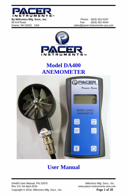
Model DA400
ANEMOMETER
User Manual
™
By Miltronics Mfg. Svcs., Inc. Phone: (603) 352-0187 95 Krif Road Fax: (603) 352-4444 Keene, NH 03431 USA [email protected]
DA400 User Manual, PN 10075 Miltronics Mfg. Svcs., Inc. Rev 3.0, 04-April-2016 www.pacer-instruments-usa.com
Copyright © 2016, Miltronics Mfg. Svcs., Inc. Page 2 of 28
INTRODUCTION
Congratulations on your purchase of a DA400 Digital Anemometer!
You now own one of the most accurate, reliable, and highly regarded airflow
measurement instruments available today.
Pacer’s model DA400 digital anemometer is a versatile instrument for
measuring air velocity in various applications such as HVAC, aerospace
development, industrial process airflow, and fluids research.
The rugged yet precise probes can be used for airstreams that have a wide range
of humidity, temperature and contaminants without compromising accuracy.
Features include choice of probe diameters, custom cable lengths, service
temperatures up to 212˚F (100˚C) at the probe, high reliability, and long life.
At the time of receipt, if more than 4 months has elapsed since the date of
the original calibration, Miltronics will provide an initial complimentary
calibration at the customer's request. If you elect to utilize this service,
please include a copy of your dated proof of purchase and a copy of the
original calibration certificate included with your unit. Call 603-352-0187
and request a Service/Repair (SR) number prior to shipping your unit.
Shipping is not included.
™
By Miltronics Mfg. Svcs., Inc. Phone: (603) 352-0187 95 Krif Road Fax: (603) 352-4444 Keene, NH 03431 USA [email protected]
DA400 User Manual, PN 10075 Miltronics Mfg. Svcs., Inc. Rev 3.0, 04-April-2016 www.pacer-instruments-usa.com
Copyright © 2016, Miltronics Mfg. Svcs., Inc. Page 3 of 28
Warranty This product is fully warranted against defective materials and/or
workmanship for a period of one year after purchase, provided it was not
improperly used. For your protection, please use this product as soon as
possible. If returned, it must be securely wrapped, sent prepaid and insured
to:
Miltronics Mfg. Svcs., Inc.
Attn: Pacer Instruments
95 Krif Road
Keene, New Hampshire 03431
USA
Please include a note with name, address, telephone number and description
of the problem. Although we provide assistance on Pacer Instrument
products both personally and through our literature, it is still the total
responsibility of the customer to determine the suitability of the product for
use in their application.
This manual is provided by Miltronics Mfg. Svcs., Inc. without any kind of
warranty. Precautions have been taken in accurately preparing this manual;
however, we neither assume responsibility for any omissions or errors that
may appear nor assume liability for any damages that result from the use of
the products in accordance with the information contained in the manual.
™
By Miltronics Mfg. Svcs., Inc. Phone: (603) 352-0187 95 Krif Road Fax: (603) 352-4444 Keene, NH 03431 USA [email protected]
DA400 User Manual, PN 10075 Miltronics Mfg. Svcs., Inc. Rev 3.0, 04-April-2016 www.pacer-instruments-usa.com
Copyright © 2016, Miltronics Mfg. Svcs., Inc. Page 4 of 28
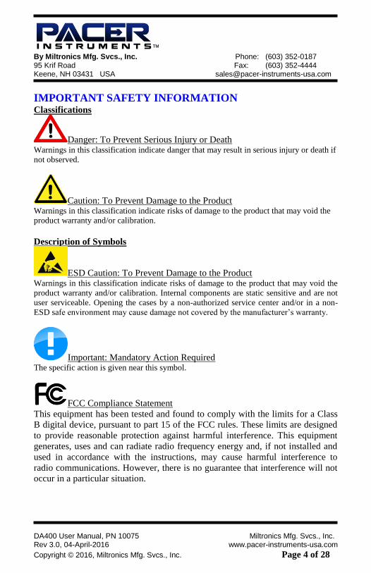
IMPORTANT SAFETY INFORMATION Classifications
Danger: To Prevent Serious Injury or Death Warnings in this classification indicate danger that may result in serious injury or death if
not observed.
Caution: To Prevent Damage to the Product Warnings in this classification indicate risks of damage to the product that may void the
product warranty and/or calibration.
Description of Symbols
ESD Caution: To Prevent Damage to the Product Warnings in this classification indicate risks of damage to the product that may void the
product warranty and/or calibration. Internal components are static sensitive and are not
user serviceable. Opening the cases by a non-authorized service center and/or in a non-
ESD safe environment may cause damage not covered by the manufacturer’s warranty.
Important: Mandatory Action Required The specific action is given near this symbol.
FCC Compliance Statement
This equipment has been tested and found to comply with the limits for a Class
B digital device, pursuant to part 15 of the FCC rules. These limits are designed
to provide reasonable protection against harmful interference. This equipment
generates, uses and can radiate radio frequency energy and, if not installed and
used in accordance with the instructions, may cause harmful interference to
radio communications. However, there is no guarantee that interference will not
occur in a particular situation.
™
By Miltronics Mfg. Svcs., Inc. Phone: (603) 352-0187 95 Krif Road Fax: (603) 352-4444 Keene, NH 03431 USA [email protected]
DA400 User Manual, PN 10075 Miltronics Mfg. Svcs., Inc. Rev 3.0, 04-April-2016 www.pacer-instruments-usa.com
Copyright © 2016, Miltronics Mfg. Svcs., Inc. Page 5 of 28
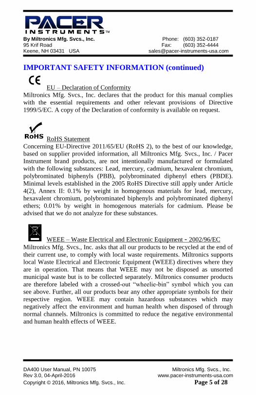
IMPORTANT SAFETY INFORMATION (continued)
EU – Declaration of Conformity
Miltronics Mfg. Svcs., Inc. declares that the product for this manual complies
with the essential requirements and other relevant provisions of Directive
1999/5/EC. A copy of the Declaration of conformity is available on request.
RoHS Statement
Concerning EU-Directive 2011/65/EU (RoHS 2), to the best of our knowledge,
based on supplier provided information, all Miltronics Mfg. Svcs., Inc. / Pacer
Instrument brand products, are not intentionally manufactured or formulated
with the following substances: Lead, mercury, cadmium, hexavalent chromium,
polybrominated biphenyls (PBB), polybrominated diphenyl ethers (PBDE).
Minimal levels established in the 2005 RoHS Directive still apply under Article
4(2), Annex II: 0.1% by weight in homogenous materials for lead, mercury,
hexavalent chromium, polybrominated biphenyls and polybrominated diphenyl
ethers; 0.01% by weight in homogenous materials for cadmium. Please be
advised that we do not analyze for these substances.
WEEE – Waste Electrical and Electronic Equipment - 2002/96/EC
Miltronics Mfg. Svcs., Inc. asks that all our products to be recycled at the end of
their current use, to comply with local waste requirements. Miltronics supports
local Waste Electrical and Electronic Equipment (WEEE) directives where they
are in operation. That means that WEEE may not be disposed as unsorted
municipal waste but is to be collected separately. Miltronics consumer products
are therefore labeled with a crossed-out “wheelie-bin” symbol which you can
see above. Further, all our products bear any other appropriate symbols for their
respective region. WEEE may contain hazardous substances which may
negatively affect the environment and human health when disposed of through
normal channels. Miltronics is committed to reduce the negative environmental
and human health effects of WEEE.
™
By Miltronics Mfg. Svcs., Inc. Phone: (603) 352-0187 95 Krif Road Fax: (603) 352-4444 Keene, NH 03431 USA [email protected]
DA400 User Manual, PN 10075 Miltronics Mfg. Svcs., Inc. Rev 3.0, 04-April-2016 www.pacer-instruments-usa.com
Copyright © 2016, Miltronics Mfg. Svcs., Inc. Page 6 of 28
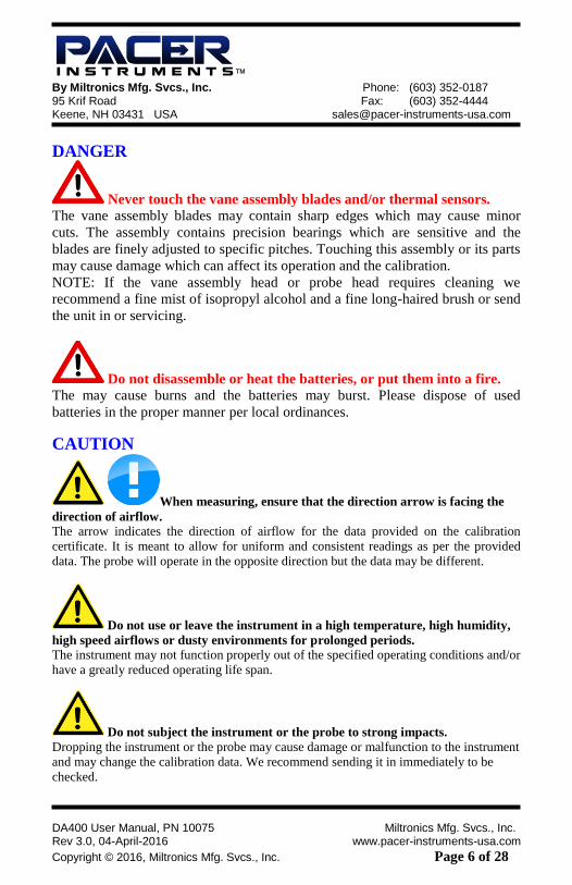
DANGER
Never touch the vane assembly blades and/or thermal sensors.
The vane assembly blades may contain sharp edges which may cause minor
cuts. The assembly contains precision bearings which are sensitive and the
blades are finely adjusted to specific pitches. Touching this assembly or its parts
may cause damage which can affect its operation and the calibration.
NOTE: If the vane assembly head or probe head requires cleaning we
recommend a fine mist of isopropyl alcohol and a fine long-haired brush or send
the unit in or servicing.
Do not disassemble or heat the batteries, or put them into a fire.
The may cause burns and the batteries may burst. Please dispose of used
batteries in the proper manner per local ordinances.
CAUTION
When measuring, ensure that the direction arrow is facing the
direction of airflow.
The arrow indicates the direction of airflow for the data provided on the calibration
certificate. It is meant to allow for uniform and consistent readings as per the provided
data. The probe will operate in the opposite direction but the data may be different.
Do not use or leave the instrument in a high temperature, high humidity,
high speed airflows or dusty environments for prolonged periods.
The instrument may not function properly out of the specified operating conditions and/or
have a greatly reduced operating life span.
Do not subject the instrument or the probe to strong impacts.
Dropping the instrument or the probe may cause damage or malfunction to the instrument
and may change the calibration data. We recommend sending it in immediately to be
checked.
™
By Miltronics Mfg. Svcs., Inc. Phone: (603) 352-0187 95 Krif Road Fax: (603) 352-4444 Keene, NH 03431 USA [email protected]
DA400 User Manual, PN 10075 Miltronics Mfg. Svcs., Inc. Rev 3.0, 04-April-2016 www.pacer-instruments-usa.com
Copyright © 2016, Miltronics Mfg. Svcs., Inc. Page 7 of 28
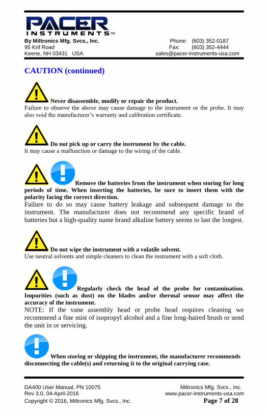
CAUTION (continued)
Never disassemble, modify or repair the product.
Failure to observe the above may cause damage to the instrument or the probe. It may
also void the manufacturer’s warranty and calibration certificate.
Do not pick up or carry the instrument by the cable.
It may cause a malfunction or damage to the wiring of the cable.
Remove the batteries from the instrument when storing for long
periods of time. When inserting the batteries, be sure to insert them with the
polarity facing the correct direction.
Failure to do so may cause battery leakage and subsequent damage to the
instrument. The manufacturer does not recommend any specific brand of
batteries but a high-quality name brand alkaline battery seems to last the longest.
Do not wipe the instrument with a volatile solvent.
Use neutral solvents and simple cleaners to clean the instrument with a soft cloth.
Regularly check the head of the probe for contamination.
Impurities (such as dust) on the blades and/or thermal sensor may affect the
accuracy of the instrument. NOTE: If the vane assembly head or probe head requires cleaning we
recommend a fine mist of isopropyl alcohol and a fine long-haired brush or send
the unit in or servicing.
When storing or shipping the instrument, the manufacturer recommends
disconnecting the cable(s) and returning it to the original carrying case.
™
By Miltronics Mfg. Svcs., Inc. Phone: (603) 352-0187 95 Krif Road Fax: (603) 352-4444 Keene, NH 03431 USA [email protected]
DA400 User Manual, PN 10075 Miltronics Mfg. Svcs., Inc. Rev 3.0, 04-April-2016 www.pacer-instruments-usa.com
Copyright © 2016, Miltronics Mfg. Svcs., Inc. Page 8 of 28
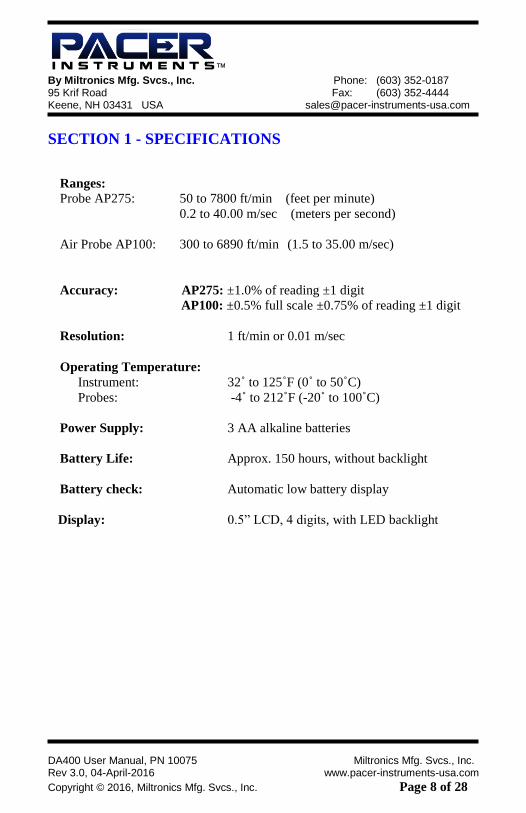
SECTION 1 - SPECIFICATIONS
Ranges:
Probe AP275: 50 to 7800 ft/min (feet per minute)
0.2 to 40.00 m/sec (meters per second)
Air Probe AP100: 300 to 6890 ft/min (1.5 to 35.00 m/sec)
Accuracy: AP275: ±1.0% of reading ±1 digit
AP100: ±0.5% full scale ±0.75% of reading ±1 digit
Resolution: 1 ft/min or 0.01 m/sec
Operating Temperature:
Instrument: 32˚ to 125˚F (0˚ to 50˚C)
Probes: -4˚ to 212˚F (-20˚ to 100˚C)
Power Supply: 3 AA alkaline batteries
Battery Life: Approx. 150 hours, without backlight
Battery check: Automatic low battery display
Display: 0.5” LCD, 4 digits, with LED backlight

™
By Miltronics Mfg. Svcs., Inc. Phone: (603) 352-0187 95 Krif Road Fax: (603) 352-4444 Keene, NH 03431 USA [email protected]
DA400 User Manual, PN 10075 Miltronics Mfg. Svcs., Inc. Rev 3.0, 04-April-2016 www.pacer-instruments-usa.com
Copyright © 2016, Miltronics Mfg. Svcs., Inc. Page 9 of 28
Options Available:
Protective Boot and Splash-Proof Seal for the Instrument
USB Communications
RS232 Communications
Analog 0-5 Volt Output
Additional Probes, AP275 or AP100
Extra extension and/or flexible rods
Custom cable lengths
Included:
(1) DA410 Instrument
(1) Vane-type probe head, choice of AP100 or AP275
(3) Rigid extension rods with handle grip
(1) Flexible extension rod
(1) Probe connection cable, 5 ft.
(3) Size AA 1.5V alkaline batteries (installed in instrument)
(1) Hard-shell carrying case with foam liner
(1) DA410 operation manual
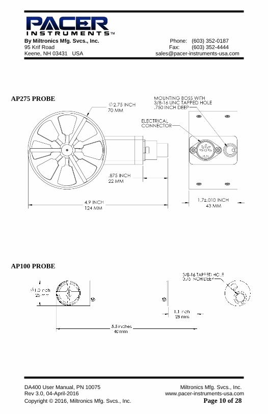
Dimensions
INSTRUMENT
™
By Miltronics Mfg. Svcs., Inc. Phone: (603) 352-0187 95 Krif Road Fax: (603) 352-4444 Keene, NH 03431 USA [email protected]
DA400 User Manual, PN 10075 Miltronics Mfg. Svcs., Inc. Rev 3.0, 04-April-2016 www.pacer-instruments-usa.com
Copyright © 2016, Miltronics Mfg. Svcs., Inc. Page 10 of 28
AP275 PROBE
AP100 PROBE
™
By Miltronics Mfg. Svcs., Inc. Phone: (603) 352-0187 95 Krif Road Fax: (603) 352-4444 Keene, NH 03431 USA [email protected]
DA400 User Manual, PN 10075 Miltronics Mfg. Svcs., Inc. Rev 3.0, 04-April-2016 www.pacer-instruments-usa.com
Copyright © 2016, Miltronics Mfg. Svcs., Inc. Page 11 of 28
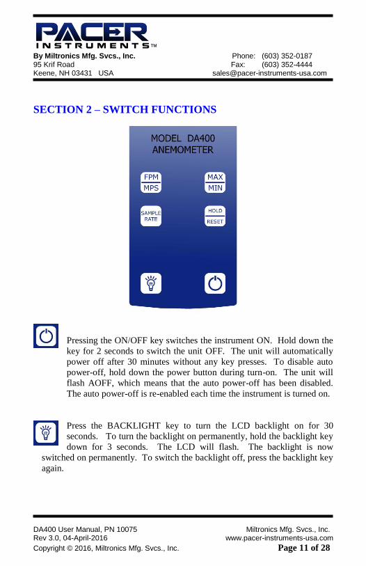
SECTION 2 – SWITCH FUNCTIONS
Pressing the ON/OFF key switches the instrument ON. Hold down the
key for 2 seconds to switch the unit OFF. The unit will automatically
power off after 30 minutes without any key presses. To disable auto
power-off, hold down the power button during turn-on. The unit will
flash AOFF, which means that the auto power-off has been disabled.
The auto power-off is re-enabled each time the instrument is turned on.
Press the BACKLIGHT key to turn the LCD backlight on for 30
seconds. To turn the backlight on permanently, hold the backlight key
down for 3 seconds. The LCD will flash. The backlight is now
switched on permanently. To switch the backlight off, press the backlight key
again.
™
By Miltronics Mfg. Svcs., Inc. Phone: (603) 352-0187 95 Krif Road Fax: (603) 352-4444 Keene, NH 03431 USA [email protected]
DA400 User Manual, PN 10075 Miltronics Mfg. Svcs., Inc. Rev 3.0, 04-April-2016 www.pacer-instruments-usa.com
Copyright © 2016, Miltronics Mfg. Svcs., Inc. Page 12 of 28
Press the FPM/MPS key to switch the measurement units from FPM
(feet per minute, 1 FPM resolution) to MPS (meters per second, 0.01
MPS resolution).
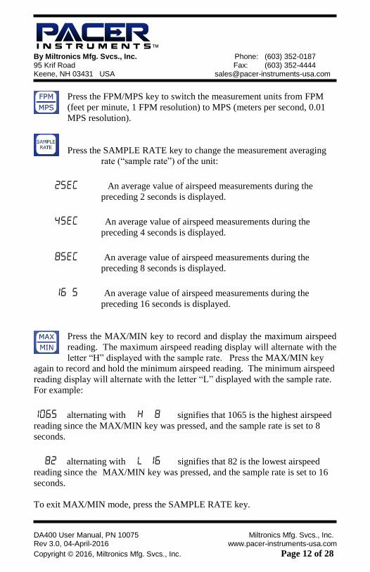
Press the SAMPLE RATE key to change the measurement averaging
rate (“sample rate”) of the unit:
An average value of airspeed measurements during the
preceding 2 seconds is displayed.
An average value of airspeed measurements during the
preceding 4 seconds is displayed.
An average value of airspeed measurements during the
preceding 8 seconds is displayed.
An average value of airspeed measurements during the
preceding 16 seconds is displayed.
Press the MAX/MIN key to record and display the maximum airspeed
reading. The maximum airspeed reading display will alternate with the
letter “H” displayed with the sample rate. Press the MAX/MIN key
again to record and hold the minimum airspeed reading. The minimum airspeed
reading display will alternate with the letter “L” displayed with the sample rate.
For example:
alternating with signifies that 1065 is the highest airspeed
reading since the MAX/MIN key was pressed, and the sample rate is set to 8
seconds.
alternating with signifies that 82 is the lowest airspeed
reading since the MAX/MIN key was pressed, and the sample rate is set to 16
seconds.
To exit MAX/MIN mode, press the SAMPLE RATE key.

™
By Miltronics Mfg. Svcs., Inc. Phone: (603) 352-0187 95 Krif Road Fax: (603) 352-4444 Keene, NH 03431 USA [email protected]
DA400 User Manual, PN 10075 Miltronics Mfg. Svcs., Inc. Rev 3.0, 04-April-2016 www.pacer-instruments-usa.com
Copyright © 2016, Miltronics Mfg. Svcs., Inc. Page 13 of 28
Press the HOLD/RESET key to freeze the current reading on the
display. HOLD is displayed on the LCD and the reading is held.
Press the HOLD/RESET key a second time to clear this mode and return the unit
to normal operation.
Press the HOLD/RESET key while in MIN/MAX mode to display BOTH the
minimum and maximum airspeed reading since the MAX/MIN key was pressed.
Once the HOLD/RESET key is pressed while in MAX/MIN mode, new airspeed
readings are no longer recorded. To return to MAX/MIN mode, press the
HOLD/RESET key again.
™
By Miltronics Mfg. Svcs., Inc. Phone: (603) 352-0187 95 Krif Road Fax: (603) 352-4444 Keene, NH 03431 USA [email protected]
DA400 User Manual, PN 10075 Miltronics Mfg. Svcs., Inc. Rev 3.0, 04-April-2016 www.pacer-instruments-usa.com
Copyright © 2016, Miltronics Mfg. Svcs., Inc. Page 14 of 28
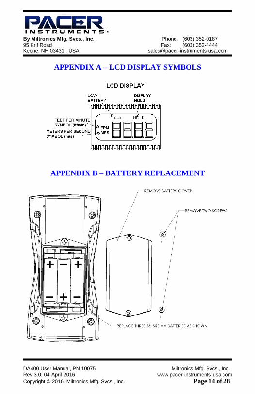
APPENDIX A – LCD DISPLAY SYMBOLS
APPENDIX B – BATTERY REPLACEMENT
™
By Miltronics Mfg. Svcs., Inc. Phone: (603) 352-0187 95 Krif Road Fax: (603) 352-4444 Keene, NH 03431 USA [email protected]
DA400 User Manual, PN 10075 Miltronics Mfg. Svcs., Inc. Rev 3.0, 04-April-2016 www.pacer-instruments-usa.com
Copyright © 2016, Miltronics Mfg. Svcs., Inc. Page 15 of 28
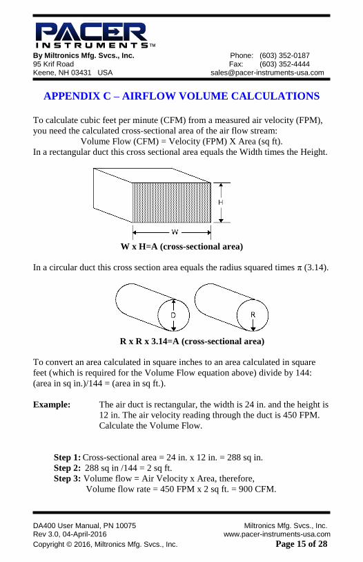
APPENDIX C – AIRFLOW VOLUME CALCULATIONS
To calculate cubic feet per minute (CFM) from a measured air velocity (FPM),
you need the calculated cross-sectional area of the air flow stream:
Volume Flow (CFM) = Velocity (FPM) X Area (sq ft).
In a rectangular duct this cross sectional area equals the Width times the Height.
W x H=A (cross-sectional area)
In a circular duct this cross section area equals the radius squared times π (3.14).
R x R x 3.14=A (cross-sectional area)
To convert an area calculated in square inches to an area calculated in square
feet (which is required for the Volume Flow equation above) divide by 144:
(area in sq in.)/144 = (area in sq ft.).
Example: The air duct is rectangular, the width is 24 in. and the height is
12 in. The air velocity reading through the duct is 450 FPM.
Calculate the Volume Flow.
Step 1: Cross-sectional area = 24 in. x 12 in. = 288 sq in.
Step 2: 288 sq in /144 = 2 sq ft.
Step 3: Volume flow = Air Velocity x Area, therefore,
Volume flow rate = 450 FPM x 2 sq ft. = 900 CFM.
™
By Miltronics Mfg. Svcs., Inc. Phone: (603) 352-0187 95 Krif Road Fax: (603) 352-4444 Keene, NH 03431 USA [email protected]
DA400 User Manual, PN 10075 Miltronics Mfg. Svcs., Inc. Rev 3.0, 04-April-2016 www.pacer-instruments-usa.com
Copyright © 2016, Miltronics Mfg. Svcs., Inc. Page 16 of 28
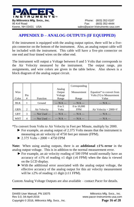
APPENDIX D – ANALOG OUTPUTS (IF EQUIPPED)
If the instrument is equipped with the analog output option, there will be a five-
pin connector on the bottom of the instrument. Also, an analog output cable will
be included with the instrument. This cable will have a five-pin connector on
one end and four tinned wires on the other end.
The instrument will output a Voltage between 0 and 5 Volts that corresponds to
the Air Velocity measured by the instrument. The output range, pin
assignments, and wire colors are given in the table below. Also shown is a
block diagram of the analog output circuit.
Corresponding
Wire Analog Output Measurement Equation* to convert from
Color
Pin
# Function
Voltage
Range Range
Volts (V) to Measurement
Value
BLK 1 Ground --- N/A --- --- N/A --- --- N/A ---
GRN 2 Air Velocity
0 to 5
Volts
0 to 10,000
FPM Air Velocity = 2000×V
GRY 3 --- Not Used --- --- N/A --- --- N/A --- --- N/A ---
WHT 4 --- Not Used --- --- N/A --- --- N/A --- --- N/A ---
*To convert from Volts to Air Velocity in Feet per Minute, multiply by 2000.
► For example, an analog output of 2.375 Volts means that the instrument is
measuring an air velocity of 4750 feet per minute (FPM).
► 2.375 Volts × 2000 = 4750 FPM
Note: When using analog outputs, there is an additional ±1% error in the
analog output voltage. This is in addition to the normal measurement error. ► For example, an air velocity reading of 500 FPM would normally have an
accuracy of ±1% of reading ±1 digit (±6 FPM) when the data is viewed
on the LCD display.
► With the additional error associated with the analog output voltage, the
effective accuracy of the analog output for this air velocity measurement
will be ±2% of reading ±1 digit (±11 FPM).
Custom Analog Voltage Outputs are also available – contact Pacer for details.

™
By Miltronics Mfg. Svcs., Inc. Phone: (603) 352-0187 95 Krif Road Fax: (603) 352-4444 Keene, NH 03431 USA [email protected]
DA400 User Manual, PN 10075 Miltronics Mfg. Svcs., Inc. Rev 3.0, 04-April-2016 www.pacer-instruments-usa.com
Copyright © 2016, Miltronics Mfg. Svcs., Inc. Page 17 of 28
Mating Cable Connector:
Binder Part No. 99-0413-00-05
Analog Output circuit block diagram and connector pin assignment
™
By Miltronics Mfg. Svcs., Inc. Phone: (603) 352-0187 95 Krif Road Fax: (603) 352-4444 Keene, NH 03431 USA [email protected]
DA400 User Manual, PN 10075 Miltronics Mfg. Svcs., Inc. Rev 3.0, 04-April-2016 www.pacer-instruments-usa.com
Copyright © 2016, Miltronics Mfg. Svcs., Inc. Page 18 of 28
APPENDIX E - USB DATA OUTPUT (IF EQUIPPED) If the instrument is equipped with the USB Communications option, there will
be a four pin male connector on the bottom of the instrument. Also, a USB
cable will be included with the instrument. This cable will have a four pin
female connector on one end and a USB Type-A connector on the other end.
USB Data Output – Instructions for Use
STEP 1: Install a Virtual COM Port (VCP) Driver on your computer.
Free VCP drivers can be downloaded for Windows, Linux, and MAC
from FTDI Ltd on their website:
http://www.ftdichip.com/Drivers/VCP.htm
We recommend downloading the setup executable, which
automatically runs and configures the drivers for you.
STEP 2: Connect the USB cable (included) to the male connector on the
bottom of your instrument. Connect the other end to a USB port on
your computer.
STEP 3: Turn the Instrument ON.
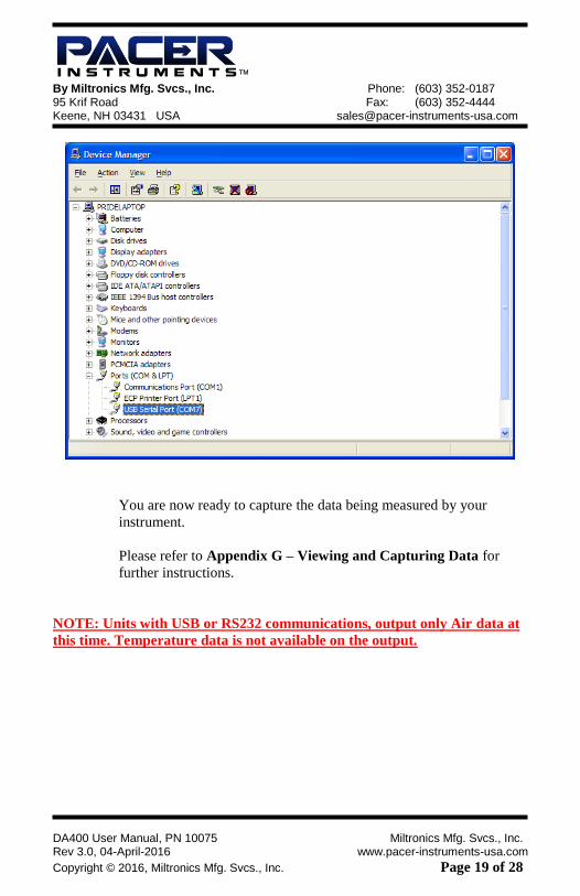
STEP 4: Verify that the Instrument has been set up as a USB Serial Port with
a unique COM port number. (You only need to do this once)
For Windows users, open the Windows Device Manager (found in
Control Panel) and verify that a USB serial port exists as shown
below.
™
By Miltronics Mfg. Svcs., Inc. Phone: (603) 352-0187 95 Krif Road Fax: (603) 352-4444 Keene, NH 03431 USA [email protected]
DA400 User Manual, PN 10075 Miltronics Mfg. Svcs., Inc. Rev 3.0, 04-April-2016 www.pacer-instruments-usa.com
Copyright © 2016, Miltronics Mfg. Svcs., Inc. Page 19 of 28
You are now ready to capture the data being measured by your
instrument.
Please refer to Appendix G – Viewing and Capturing Data for
further instructions.
NOTE: Units with USB or RS232 communications, output only Air data at
this time. Temperature data is not available on the output.
™
By Miltronics Mfg. Svcs., Inc. Phone: (603) 352-0187 95 Krif Road Fax: (603) 352-4444 Keene, NH 03431 USA [email protected]
DA400 User Manual, PN 10075 Miltronics Mfg. Svcs., Inc. Rev 3.0, 04-April-2016 www.pacer-instruments-usa.com
Copyright © 2016, Miltronics Mfg. Svcs., Inc. Page 20 of 28
APPENDIX F – RS232 COMMUNICATIONS (IF EQUIPPED)
If the instrument is equipped with the RS232 Communications option, there will
be a three pin male connector on the bottom of the instrument. Also, an RS232
cable will be included with the instrument. This cable will have a three pin
female connector on one end and a DB9 Female connector on the other end.
RS232 Data Output – Instructions for Use
STEP 1: Connect the RS232 cable (included) to the female connector on the
bottom of your instrument. Connect the other end to an RS232 port
on your computer.
STEP 3: Turn the Instrument ON.
STEP 4: Verify that the Instrument has been set up as a RS232 Serial Port
with a unique COM port number. (You only need to do this once).
For Windows users, open the Windows Device Manager (found in
Control Panel) and verify that a serial port exists.
You are now ready to capture the data being measured by your
instrument.
Please refer to Appendix G – Viewing and Capturing Data for
further instructions.
™
By Miltronics Mfg. Svcs., Inc. Phone: (603) 352-0187 95 Krif Road Fax: (603) 352-4444 Keene, NH 03431 USA [email protected]
DA400 User Manual, PN 10075 Miltronics Mfg. Svcs., Inc. Rev 3.0, 04-April-2016 www.pacer-instruments-usa.com
Copyright © 2016, Miltronics Mfg. Svcs., Inc. Page 21 of 28
APPENDIX G – VIEWING AND CAPTURING DATA (IF EQUIPPED WITH EITHER USB OR RS232 OUTPUTS)
NOTE: HyperTerminal is no longer included with Windows Vista or later packages.
Previous manuals referenced this program. We now reference, Parallax Serial Terminal.
There are many terminal emulator programs available on the market. It is up to the
end-user to determine which program is compatible with his/her system, what settings
it may require and the Pacer Instruments/Miltronics product being used. Miltronics
Mfg. Svcs., Inc. does not endorse or recommend any of these programs and assumes
no liability for their use.
There are many ways to capture the serial port data from the Pacer Instrument.
The simplest method is to use a terminal emulator program.
Using a terminal emulator allows the serial COM port to be opened, with the
below port settings, and real-time data to be viewed from the instrument. One
such terminal emulator program is Parallax Serial Terminal, available from
www.parallax.com.
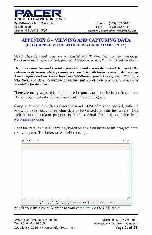
Open the Parallax Serial Terminal, based on how you installed the program onto
your computer. The below screen will come up.
Attach your instrument & probe to your computer via the USB cable.
™
By Miltronics Mfg. Svcs., Inc. Phone: (603) 352-0187 95 Krif Road Fax: (603) 352-4444 Keene, NH 03431 USA [email protected]
DA400 User Manual, PN 10075 Miltronics Mfg. Svcs., Inc. Rev 3.0, 04-April-2016 www.pacer-instruments-usa.com
Copyright © 2016, Miltronics Mfg. Svcs., Inc. Page 22 of 28
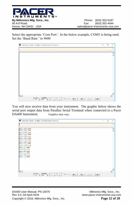
Select the appropriate ‘Com Port:’. In the below example, COM5 is being used.
Set the ‘Baud Rate:’ to 9600
You will now receive data from your instrument. The graphic below shows the
serial port output data from Parallax Serial Terminal when connected to a Pacer
DA400 Instrument. Graphics may vary.
™
By Miltronics Mfg. Svcs., Inc. Phone: (603) 352-0187 95 Krif Road Fax: (603) 352-4444 Keene, NH 03431 USA [email protected]
DA400 User Manual, PN 10075 Miltronics Mfg. Svcs., Inc. Rev 3.0, 04-April-2016 www.pacer-instruments-usa.com
Copyright © 2016, Miltronics Mfg. Svcs., Inc. Page 23 of 28
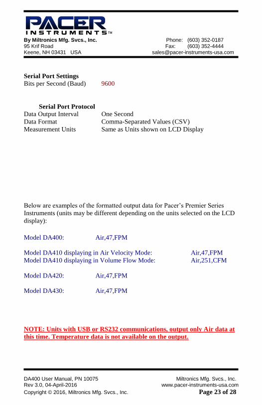
Serial Port Settings
Bits per Second (Baud) 9600
Serial Port Protocol
Data Output Interval One Second
Data Format Comma-Separated Values (CSV)
Measurement Units Same as Units shown on LCD Display
Below are examples of the formatted output data for Pacer’s Premier Series
Instruments (units may be different depending on the units selected on the LCD
display):
Model DA400: Air,47,FPM
Model DA410 displaying in Air Velocity Mode: Air,47,FPM
Model DA410 displaying in Volume Flow Mode: Air,251,CFM
Model DA420: Air,47,FPM
Model DA430: Air,47,FPM
NOTE: Units with USB or RS232 communications, output only Air data at
this time. Temperature data is not available on the output.

™
By Miltronics Mfg. Svcs., Inc. Phone: (603) 352-0187 95 Krif Road Fax: (603) 352-4444 Keene, NH 03431 USA [email protected]
DA400 User Manual, PN 10075 Miltronics Mfg. Svcs., Inc. Rev 3.0, 04-April-2016 www.pacer-instruments-usa.com
Copyright © 2016, Miltronics Mfg. Svcs., Inc. Page 24 of 28
Exporting and Graphing Data Exporting serial port instrument data from the Pacer Instrument to a spreadsheet
application such as Microsoft Excel or OpenOffice Calc allows the data to
graphed or recorded.
The simplest way to export the instrument data is to use a terminal emulator
program, like Parallax Serial Terminal, and either capture the serial data/text to a
file (menu selection) or to manually highlight, copy, and then paste the
instrument data into an editor such as Windows Notepad.
Once you have the instrument data in a file, save the file as a .CSV type (e.g.,
InstrumentData.csv).
Open the file in a spreadsheet application such as Microsoft Excel or
OpenOffice Calc. A graph of the data as shown below can now be generated.
™
By Miltronics Mfg. Svcs., Inc. Phone: (603) 352-0187 95 Krif Road Fax: (603) 352-4444 Keene, NH 03431 USA [email protected]
DA400 User Manual, PN 10075 Miltronics Mfg. Svcs., Inc. Rev 3.0, 04-April-2016 www.pacer-instruments-usa.com
Copyright © 2016, Miltronics Mfg. Svcs., Inc. Page 25 of 28
Notes:

™
By Miltronics Mfg. Svcs., Inc. Phone: (603) 352-0187 95 Krif Road Fax: (603) 352-4444 Keene, NH 03431 USA [email protected]
DA400 User Manual, PN 10075 Miltronics Mfg. Svcs., Inc. Rev 3.0, 04-April-2016 www.pacer-instruments-usa.com
Copyright © 2016, Miltronics Mfg. Svcs., Inc. Page 26 of 28
Notes:
™
By Miltronics Mfg. Svcs., Inc. Phone: (603) 352-0187 95 Krif Road Fax: (603) 352-4444 Keene, NH 03431 USA [email protected]
DA400 User Manual, PN 10075 Miltronics Mfg. Svcs., Inc. Rev 3.0, 04-April-2016 www.pacer-instruments-usa.com
Copyright © 2016, Miltronics Mfg. Svcs., Inc. Page 27 of 28
CALIBRATION
To maintain your instrument in top working order, we recommend
that you send it back to us for calibration each year, beginning one
year after purchase.
Our NIST-Traceable multi-point calibration services include
ensuring the instrument performs within its accuracy tolerance,
making any necessary adjustments, and inspecting all aspects of
the instrument’s functionality so that you’ll have another year of
dependable service. Calibration also includes a complimentary
firmware upgrade so that you know you’ll have the latest advances
in accuracy and reliability in your instrument.
Additional points other than our standard calibration are also
available from the factory. We can offer precise calibration
tailored to your specific measurement needs using our state-of-the-
art facilities and calibration equipment.
Please contact us or visit our website for the latest information on
calibrating your instrument.

™
By Miltronics Mfg. Svcs., Inc. Phone: (603) 352-0187 95 Krif Road Fax: (603) 352-4444 Keene, NH 03431 USA [email protected]
DA400 User Manual, PN 10075 Miltronics Mfg. Svcs., Inc. Rev 3.0, 04-April-2016 www.pacer-instruments-usa.com
Copyright © 2016, Miltronics Mfg. Svcs., Inc. Page 28 of 28
™
™
Miltronics Mfg. Svcs., Inc. 95 Krif Road
Keene, New Hampshire 03431
USA
(800) 283-1141
(603) 352-0187
Main Fax: (603) 352-4444 [email protected]
www.pacer-instruments-usa.com
Copyright © 2016, Miltronics Mfg. Svcs., Inc.