Pace IPTV Receivers Product Manual - AT&T · Pace IPTV Receivers Product Manual Supports Models...
36
AT&T U-verse Pace IPTV Receivers Product Manual Supports Models IPH8005, IPH8010, and IPH8110 For use with your AT&T U-verse ® TV service
Transcript of Pace IPTV Receivers Product Manual - AT&T · Pace IPTV Receivers Product Manual Supports Models...

AT&T U-verse
PaceIPTV ReceiversProduct ManualSupports Models IPH8005, IPH8010, and IPH8110For use with your AT&T U-verse® TV service


Contents
Introduction . . . . . . . . . . . . . . . . . . . . . . . . . . . . . . . . . . . . 5Package contents. . . . . . . . . . . . . . . . . . . . . . . . . . . . . . . . . . . . . . . . . . . . . . . . . . . 6Serial number . . . . . . . . . . . . . . . . . . . . . . . . . . . . . . . . . . . . . . . . . . . . . . . . . . . . . . 6Front panel . . . . . . . . . . . . . . . . . . . . . . . . . . . . . . . . . . . . . . . . . . . . . . . . . . . . . . . . 7Back panel . . . . . . . . . . . . . . . . . . . . . . . . . . . . . . . . . . . . . . . . . . . . . . . . . . . . . . . . 8
Connecting the Receiver . . . . . . . . . . . . . . . . . . . . . . . . . . 9Connect the receiver to the home network. . . . . . . . . . . . . . . . . . . . . . . . . . . . . . . 10Connect the receiver to the TV. . . . . . . . . . . . . . . . . . . . . . . . . . . . . . . . . . . . . . . . 11
Determining the type of connection to use. . . . . . . . . . . . . . . . . . . . . . . . . . . . . 11Using an HDMI connection . . . . . . . . . . . . . . . . . . . . . . . . . . . . . . . . . . . . . . . . 13Using a DVI connection with digital audio . . . . . . . . . . . . . . . . . . . . . . . . . . . . . 14Using a DVI connection with analog audio . . . . . . . . . . . . . . . . . . . . . . . . . . . . 15Using a component video connection with digital audio . . . . . . . . . . . . . . . . . . 16Using a component video connection with analog audio . . . . . . . . . . . . . . . . . . 17Using a composite video connection . . . . . . . . . . . . . . . . . . . . . . . . . . . . . . . . . 18Using an RF coaxial connection . . . . . . . . . . . . . . . . . . . . . . . . . . . . . . . . . . . . 19Connecting the receiver to a home theater system . . . . . . . . . . . . . . . . . . . . . . 20
Plug in the receiver. . . . . . . . . . . . . . . . . . . . . . . . . . . . . . . . . . . . . . . . . . . . . . . . . 21
Troubleshooting and Support. . . . . . . . . . . . . . . . . . . . . . 22Troubleshooting . . . . . . . . . . . . . . . . . . . . . . . . . . . . . . . . . . . . . . . . . . . . . . . . . . . 22Frequently asked questions . . . . . . . . . . . . . . . . . . . . . . . . . . . . . . . . . . . . . . . . . . 24Picture formats . . . . . . . . . . . . . . . . . . . . . . . . . . . . . . . . . . . . . . . . . . . . . . . . . . . . 25
Safety Information . . . . . . . . . . . . . . . . . . . . . . . . . . . . . . 26Warnings . . . . . . . . . . . . . . . . . . . . . . . . . . . . . . . . . . . . . . . . . . . . . . . . . . . . . . . . 26Other warnings . . . . . . . . . . . . . . . . . . . . . . . . . . . . . . . . . . . . . . . . . . . . . . . . . . . . 26Important safety instructions . . . . . . . . . . . . . . . . . . . . . . . . . . . . . . . . . . . . . . . . . 27Safety aspects of connections . . . . . . . . . . . . . . . . . . . . . . . . . . . . . . . . . . . . . . . . 29Note to the installer . . . . . . . . . . . . . . . . . . . . . . . . . . . . . . . . . . . . . . . . . . . . . . . . 30
Compliance Information . . . . . . . . . . . . . . . . . . . . . . . . . . 31Regulatory information . . . . . . . . . . . . . . . . . . . . . . . . . . . . . . . . . . . . . . . . . . . . . . 31
Declaration of Conformity . . . . . . . . . . . . . . . . . . . . . . . . . . . . . . . . . . . . . . . . . 31Trademarks and licenses . . . . . . . . . . . . . . . . . . . . . . . . . . . . . . . . . . . . . . . . . . . . 33
Open source licenses . . . . . . . . . . . . . . . . . . . . . . . . . . . . . . . . . . . . . . . . . . . . 33
3

4
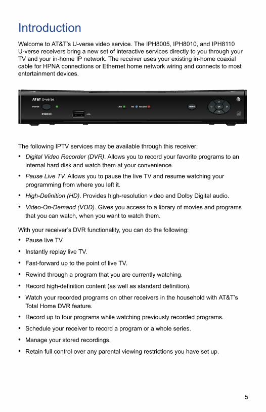
IntroductionWelcome to AT&T’s U-verse video service. The IPH8005, IPH8010, and IPH8110 U-verse receivers bring a new set of interactive services directly to you through your TV and your in-home IP network. The receiver uses your existing in-home coaxial cable for HPNA connections or Ethernet home network wiring and connects to most entertainment devices.
The following IPTV services may be available through this receiver:
• Digital Video Recorder (DVR). Allows you to record your favorite programs to an
internal hard disk and watch them at your convenience.
• Pause Live TV. Allows you to pause the live TV and resume watching your
programming from where you left it.
• High-Definition (HD). Provides high-resolution video and Dolby Digital audio.
• Video-On-Demand (VOD). Gives you access to a library of movies and programs
that you can watch, when you want to watch them.
With your receiver’s DVR functionality, you can do the following:
• Pause live TV.
• Instantly replay live TV.
• Fast-forward up to the point of live TV.
• Rewind through a program that you are currently watching.
• Record high-definition content (as well as standard definition).
• Watch your recorded programs on other receivers in the household with AT&T’s
Total Home DVR feature.
• Record up to four programs while watching previously recorded programs.
• Schedule your receiver to record a program or a whole series.
• Manage your stored recordings.
• Retain full control over any parental viewing restrictions you have set up.
POWER
IPH8XXX
LINK RECORDHD MENU OK
5

You control your receiver’s DVR functions and other U-verse features using your remote control. Consult the information provided by AT&T U-verse for more details or visit the online feature guide at www.att.com/userguides.
Package contentsThe receiver carton contains the following items:
• IPH8005, IPH8010, or IPH8110 receiver. A TV receiver that supports high-definition
(HD) and standard-definition (SD) video decoding.
• Power cord and adapter. A 12 volt power supply unit that provides power from an
AC wall outlet to the receiver.
• Product Manual. A product manual that provides connection information for the
IPH8005, IPH8010, and IPH8110 receivers.
Before using the receiver, read the “Important safety instructions” on page 27 of this manual. This manual describes how to connect your receiver to both your in-home IP network and your entertainment system. The manual also outlines safeguards and installation information. The safety information contained in this manual was developed and provided solely by the receiver manufacturer, Pace Americas.
Serial numberAt times AT&T may ask for your serial number. To find the serial number, look on the bottom of the receiver for the label. The serial number is the numeric code to the right of the letters “S/N” on the label, as shown on the following sample label.
Use the space below to record the serial number for your receiver:
_________________________________
GUID: c440f5e7-2b49-41f5-8b07-b9f478946384
Model: IPH8XXXAT&T U-verse DVRBasic SD/HDRating: 12V 1.5A
HW: AKSW: IPTVL- 1015Factory ID: CCT Made in Thailand
Manufactured under license from Dolby Laboratories. Dolby and the double-D symbol are trademarks of Dolby Laboratories.
HPNA MAC: 48:44:48:de:ac:8b
Pace IPH8010
LISTEDLISTEDI.T.E.
E205389
USUSCC
Date of Mfg: 12/2013
S/N: 1234567890123
ICES/NMB-003 B
P/N: 296-0411700
Serial numberlocation
6

Front panelThe following illustration shows the buttons, lights, and connectors on the front of the receiver.
Power buttonTurns the set-top box on or off.
Power lightLights green when the set-top box is powered on. Blinks when receiving input from the remote control or when the front-panel buttons are pressed.
Model numberIdentifies the model number of the receiver.
USB portReserved for future use.
Link lightLights green when the box has a good connection to the AT&T network.
HD lightLights blue to indicate the receiver is configured to display high-definition programming when available.
Record lightLights red when the DVR is recording content.
Menu buttonLaunches the on-screen menu.
Navigation buttonsNavigates to on-screen menu options.
OK buttonConfirms the on-screen menu choice.
POWER
IPH8XXX
LINK RECORDHD MENU OK
Power button Menu button
Navigation buttons
USB port
Model number Status lights
OK button
Power light
7

Back panelThe following illustration shows the ports and connectors on the back of the receiver.
TO WALL (VIDEO IN)Connects the HPNAv3 in-home network over coaxial cable, if applicable.
NETWORKConnects the Ethernet network cable, if applicable.
Y Pb PrConnects the receiver to a high-definition TV or home theater receiver using a component video connection.
VIDEO OUTConnects the receiver to a standard-definition TV using a composite video connection.
AUDIO Connects the receiver to a TV or home theater receiver using an analog audio connection.
TO TVConnects the set-top box to the RF/Antenna connector on your TV or VCR (optional).
OPTICALConnects the receiver to a TV or home theater receiver using a digital audio connection.
HDMIConnects the receiver to a high-definition TV or home theater receiver using an HDMI connection.
POWERConnects the power adapter to the receiver. The LED lights green when the receiver is receiving power from the wall outlet.
TO WALL(VIDEO IN)
AUDIO
Y Pb Pr
VIDEO OUT
R LNETWORKTO TV
OPTICALPOWER
+12V1.5A MAX.
Coaxial input
Component videooutput
Analog audiooutput
HDMI output
Network port
Composite videooutput Power
Digital audiooutput (optical)
RFoutput
8

Connecting the ReceiverTo view programs broadcast in high definition, your receiver must be connected to a suitable high-definition TV or computer monitor. Your receiver is also compatible with standard-definition TVs.
Your receiver should have been connected to your TV by your installer. However, if you need to disconnect and re-connect your equipment, please read the information in this chapter carefully before you re-connect the receiver to your TV.
Before you begin:
• Do not connect your receiver (or any other equipment such as a TV or DVD player)
to the AC power supply until you have properly connected all the other cables.
• Disconnect your receiver from the AC power supply before you disconnect any
other equipment from its rear panel.
• To disconnect power from your receiver, always detach the power supply unit from
the wall electrical outlet (rather than removing the cord from your receiver). You should install your receiver near a wall electrical outlet that is easily accessible.
• The TO WALL (VIDEO IN) connector is designed for connection to an HPNAv3 in-
home network over coaxial cable. You must not connect any other equipment to this input.
• Any cable connected to the OPTICAL connector must be a fiber optic TOSLINK
connector, not a regular audio cable.
• If you are in any doubt about the power supply cord, its plug or its connection,
consult a qualified electrician.
• Use the TV remote to set the input to match the connector selected on the back of
the TV.
9

Connect the receiver to the home networkIf you connect to your IPTV signal from your HPNAv3 in-home network over coaxial cable, use the TO WALL (VIDEO IN) connector on the back panel of the receiver to connect to the HPNAv3 in-home network through a coaxial cable.
If you connect to your home network with an Ethernet (Cat-5) cable, use the NETWORK connector on the back panel of the receiver to connect to the home network Ethernet port.
Note: Use only one of these connections to access your home network.
TO WALL(VIDEO IN)
AUDIO
Y Pb Pr
VIDEO OUT
R LNETWORKTO TV
OPTICALPOWER
+12V1.5A MAX.
Wall outlet
Coaxial cable
Receiver
TO WALL(VIDEO IN)
AUDIO
Y Pb Pr
VIDEO OUT
R LNETWORKTO TV
OPTICALPOWER
+12V1.5A MAX.
Wall outlet
Ethernet cable
Receiver
10

Connect the receiver to the TVThe connections for an HD or SD TV are different, and before you begin, you must determine if your TV is HD or SD. Your TV must receive HD signals for you to enjoy the benefits of HDTV. Refer to the manual that came with your TV for more information.
Determining the type of connection to useThe connection type you use is determined by the type of connections on your TV or home theater receiver. The following tables list the connectors that can be used for high-definition TVs and standard-definition TVs, respectively.
Connections for HDTVTo use the receiver with high-definition TVs, you need to use one of the following connections to view HD content. For more information about making HDTV connections, check the owner’s manual for your TV and the appropriate connection diagrams in this manual.
Note: The labeling on your HDTV may vary slightly from the illustrations shown in the table.
Name Connector Description
HDMI Provides the HD connection using an HDMI input on the TV. The HDMI-to-HDMI connection transmits both HD video and digital audio. For connection information using HDMI, see “Using an HDMI connection” on page 13.
DVI Provides the HD connection using a DVI input on the TV. The HDMI-to-DVI connection transmits HD video only. For digital audio, use a TOSLINK fiber optic cable to connect to the digital audio connector on the TV. For standard audio, use the Audio L/R RCA connectors. For connection information using DVI, see “Using a DVI connection with digital audio” on page 14.
Component video Provides the HD connection using the component video input on the TV. For digital audio, use a TOSLINK fiber optic cable to connect to the digital audio connector on the TV. For standard audio, use the Audio L/R RCA connectors. For connection information using component video, see “Using a component video connection with digital audio” on page 16.
HDMI IN
1
2
3
HDMI IN
1
2
3
DVI IN
L
R
AUDIO
L
R
AUDIO
DVI IN
OPTICAL IN
1
2
Y
PB
PR
COMPONENT VIDEO IN
L
R
AUDIO
Y
PB
PR
L
R
AUDIO
COMPONENT VIDEO IN
OPTICAL IN
1
2
11

Connections for SDTVTo use the receiver with standard-definition TVs, you need to use one of the following connections to view SD content. For more information about making SDTV connections, check the owner’s manual for your TV and the appropriate connection diagrams in this manual.
Note: The labeling on your SDTV may vary slightly from the illustrations shown in the table.
Name Connector Description
Component video Provides the SD connection using the component video input on the TV. For standard audio, use the Audio L/R RCA connectors. For connection information using component video, see “Using a component video connection with analog audio” on page 17.
Composite video Provides the SD connection using the composite video input on the TV. For standard audio, use the Audio L/R RCA connectors. For connection information using composite video, see “Using a composite video connection” on page 18.
RF coaxial Provides the SD connection using the coaxial input on the TV. The RF coaxial connection transmits standard video and audio. For connection information using an RF coaxial cable, see “Using an RF coaxial connection” on page 19.
Y
PB
PR
COMPONENT VIDEO IN
L
R
AUDIO
Y
PB
PR
L
R
AUDIO
COMPONENT VIDEO IN
VIDEO
COMPOSITEVIDEO IN
L
R
AUDIO
VIDEO
COMPOSITEVIDEO IN
L
R
AUDIO
ANT (75 )
IN
OUT
12

Using an HDMI connectionThe HDMI connector provides the connection to an HDTV. HDMI carries signals for video and audio.
To connect the receiver to the TV using an HDMI cable:
1. Insert one end of the HDMI cable into the HDMI connector on the receiver.
2. Insert the other end of the HDMI cable into an available HDMI connector on the TV.
Note: The HDMI connector on the TV must support HDCP (high-bandwidth digital content protection).
Television
HDMI IN
1
2
3
ANT (75 )
IN
OUT
VIDEO
COMPOSITEVIDEO IN
L
R
AUDIO
DVI IN
L
R
AUDIO
AUDIO OUT
L
R
OPTICAL IN
Y
PB
PR
COMPONENT VIDEO IN
L
R
AUDIO
1
2
HDMI cable
Receiver
TO WALL(VIDEO IN)
AUDIO
Y Pb Pr
VIDEO OUT
R LNETWORKTO TV
OPTICALPOWER
+12V1.5A MAX.
HDMI IN
1
2
3
13

Using a DVI connection with digital audioThe HDMI connector on the receiver can provide the connection to an HDTV with a DVI input. If your HDTV has a DVI (Digital Visual Interface) connector, you need an HDMI-to-DVI cable and a separate digital optical audio cable.
To connect the receiver to the TV using an HDMI-to-DVI cable and digital audio cable:
1. Insert the HDMI end of the cable into the HDMI connector on the receiver.
2. Insert the 24-pin DVI end of the cable into the DVI connector on the TV.
3. Connect the fiber optic audio cable to the OPTICAL connector on the receiver.
4. Connect the other end of the fiber optic audio cable to an available OPTICAL IN connector on the TV.
TelevisionANT (75 )
IN
OUT
VIDEO
COMPOSITEVIDEO IN
L
R
AUDIO
DVI IN
L
R
AUDIO
AUDIO OUT
L
R
OPTICAL IN
Y
PB
PR
COMPONENT VIDEO IN
L
R
AUDIO1
2
Receiver
HDMI to DVI cable
TO WALL(VIDEO IN)
AUDIO
Y Pb Pr
VIDEO OUT
R LNETWORKTO TV
OPTICALPOWER
+12V1.5A MAX.
Digital optical audio cable
L
R
AUDIO
DVI IN
14

Using a DVI connection with analog audioThe HDMI connector on the receiver can provide the connection to an HDTV with a DVI input. If your HDTV has a DVI (Digital Visual Interface) connector, you need an HDMI-to-DVI cable and a separate analog audio cable.
To connect the receiver to the TV using an HDMI-to-DVI cable and analog audio cable:
1. Insert the HDMI end of the cable into the HDMI connector on the receiver.
2. Insert the 24-pin DVI end of the cable into the DVI connector on the TV.
3. Connect the color-coded analog audio cable to the AUDIO L (white) and R (red) connectors on the receiver.
4. Connect the other end of the color-coded analog audio cable to the AUDIO L (white) and R (red) connectors on the TV.
TelevisionANT (75 )
IN
OUT
VIDEO
COMPOSITEVIDEO IN
L
R
AUDIO
DVI IN
L
R
AUDIO
AUDIO OUT
L
R
OPTICAL IN
Y
PB
PR
COMPONENT VIDEO IN
L
R
AUDIO
1
2
Receiver
Analog audio cable
HDMI to DVI cable
TO WALL(VIDEO IN)
AUDIO
Y Pb Pr
VIDEO OUT
R LNETWORKTO TV
OPTICALPOWER
+12V1.5A MAX.
L
R
AUDIO
DVI IN
15

Using a component video connection with digital audioComponent video uses the Y Pb Pr (green, blue, and red) connectors to provide component video signals to an HDTV or SDTV. You must connect the audio signal separately using a digital optical audio cable.
To connect the receiver to the TV using a component video cable and digital audio cable:
1. Insert the connectors on the color-coded component video cable into the Y Pb Pr (green, blue, and red) connectors on the receiver.
2. Insert the other end of the component video cable into the COMPONENT VIDEO Y Pb Pr (green, blue, and red) connectors on the TV.
3. Connect the fiber optic audio cable to the OPTICAL connector on the receiver.
4. Connect the other end of the fiber optic audio cable to an available OPTICAL IN connector on the TV.
Television
ANT (75 )
IN
OUT
VIDEO
COMPOSITEVIDEO IN
L
R
AUDIO
AUDIO OUT
L
R
OPTICAL IN
Y
PB
PR
COMPONENT VIDEO IN
L
R
AUDIO
1
2
Receiver
TO WALL(VIDEO IN)
AUDIO
Y Pb Pr
VIDEO OUT
R LNETWORKTO TV
OPTICALPOWER
+12V1.5A MAX.
Y
PB
PR
L
R
AUDIO
COMPONENT VIDEO IN
Component video cable
Digital optical audio cable
16
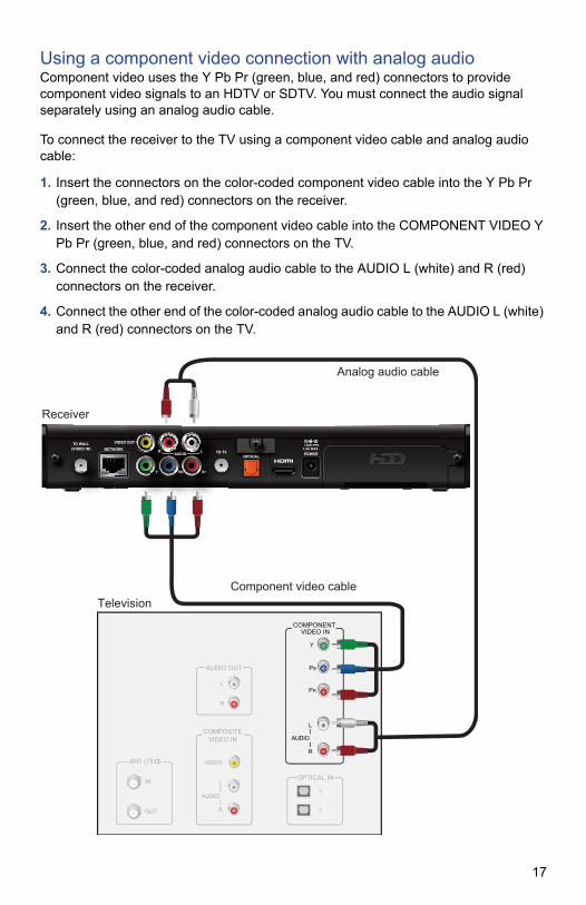
Using a component video connection with analog audioComponent video uses the Y Pb Pr (green, blue, and red) connectors to provide component video signals to an HDTV or SDTV. You must connect the audio signal separately using an analog audio cable.
To connect the receiver to the TV using a component video cable and analog audio cable:
1. Insert the connectors on the color-coded component video cable into the Y Pb Pr (green, blue, and red) connectors on the receiver.
2. Insert the other end of the component video cable into the COMPONENT VIDEO Y Pb Pr (green, blue, and red) connectors on the TV.
3. Connect the color-coded analog audio cable to the AUDIO L (white) and R (red) connectors on the receiver.
4. Connect the other end of the color-coded analog audio cable to the AUDIO L (white) and R (red) connectors on the TV.
Television
ANT (75 )
IN
OUT
VIDEO
COMPOSITEVIDEO IN
L
R
AUDIO
AUDIO OUT
L
R
OPTICAL IN
Y
PB
PR
COMPONENT VIDEO IN
L
R
AUDIO
1
2
Receiver
TO WALL(VIDEO IN)
AUDIO
Y Pb Pr
VIDEO OUT
R LNETWORKTO TV
OPTICALPOWER
+12V1.5A MAX.
Y
PB
PR
L
R
AUDIO
COMPONENT VIDEO IN
Component video cable
Analog audio cable
17

Using a composite video connectionComposite video provides the video connection to a SDTV. You must connect the audio signal separately.
To connect the receiver to the TV using a composite video cable:
1. Insert the yellow video connector on the color-coded composite video cable into the VIDEO OUT (yellow) connector on the receiver.
2. Insert the other end of the composite video cable into the VIDEO IN (yellow) connector on the TV.
3. Connect the color-coded audio cable to the AUDIO L (white) and R (red) connectors on the receiver.
4. Connect the other end of the color-coded audio cable to the AUDIO L (white) and R (red) connectors on the TV.
Television
ANT (75 )
IN
OUT
VIDEO
COMPOSITEVIDEO IN
L
R
AUDIO
AUDIO OUT
L
R
OPTICAL IN
1
2
Receiver
Audio cable
Composite video cable
TO WALL(VIDEO IN)
AUDIO
Y Pb Pr
VIDEO OUT
R LNETWORKTO TV
OPTICALPOWER
+12V1.5A MAX.
VIDEO
COMPOSITEVIDEO IN
L
R
AUDIO
18

Using an RF coaxial connectionThe RF coaxial connector provides the connection to an SDTV. The RF coaxial cable carries signals for standard video and audio.
To connect the receiver to the TV using an RF coaxial cable:
1. Insert one end of the RF coaxial cable into the TO TV connector on the receiver.
2. Insert the other end of the RF coaxial cable into an available RF coaxial connector on the TV.
Note: If you use an RF coaxial cable to connect the receiver to your TV, you must tune your TV to a supported VHF output channel, which is either channel 3 or 4. Contact AT&T U-verse to find out which channel is used in your location. Consult the manuals supplied with your TV for additional tuning information.
Television
HDMI IN
1
2
3
ANT (75 )
IN
OUT
VIDEO
COMPOSITEVIDEO IN
L
R
AUDIO
DVI IN
L
R
AUDIO
AUDIO OUT
L
R
OPTICAL IN
Y
PB
PR
COMPONENT VIDEO IN
L
R
AUDIO
1
2
RF coaxial cable
Receiver
TO WALL(VIDEO IN)
AUDIO
Y Pb Pr
VIDEO OUT
R LNETWORKTO TV
OPTICALPOWER
+12V1.5A MAX.
HDMI IN
1
2
3
19

Connecting the receiver to a home theater systemIf your television viewing configuration includes a home theater system, you can connect the receiver directly to the home theater system receiver. The following example uses the HDMI port to provide the video and audio signals from the receiver to the home theater system.
Note: Consult the manual that came with your home theater system for information on connecting video and audio devices to the home theater receiver.
To connect the receiver to a home theater receiver using HDMI:
1. Insert one end of the HDMI cable into the HDMI connector on the receiver.
2. Insert the other end of the HDMI cable into an available HDMI IN connector on the home theater receiver.
3. Connect a second HDMI cable into an available HDMI OUT connector on the home theater receiver.
4. Insert the other end of the second HDMI cable into an available HDMI connector on the TV.
Television
HDMI IN
1
2
3
ANT (75 )
IN
OUT
OPTICAL IN
1
2
Receiver
HDMI cableto receiver
HDMI cableto TV
TO WALL(VIDEO IN)
AUDIO
Y Pb Pr
VIDEO OUT
R LNETWORKTO TV
OPTICALPOWER
+12V1.5A MAX.
Home theater receiver
HDMI
1 2 3 OUT
OPTICAL IN
1
2
DVD
VIDEO
L
R
AUDIO
SAT
VIDEO
L
R
AUDIO
COMPONENT VIDEO
1 2 3
20
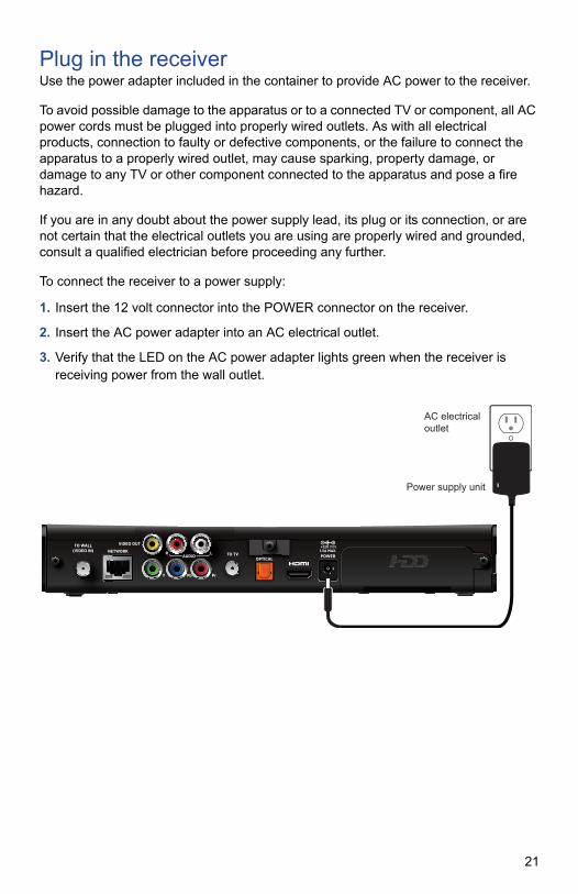
Plug in the receiverUse the power adapter included in the container to provide AC power to the receiver.
To avoid possible damage to the apparatus or to a connected TV or component, all AC power cords must be plugged into properly wired outlets. As with all electrical products, connection to faulty or defective components, or the failure to connect the apparatus to a properly wired outlet, may cause sparking, property damage, or damage to any TV or other component connected to the apparatus and pose a fire hazard.
If you are in any doubt about the power supply lead, its plug or its connection, or are not certain that the electrical outlets you are using are properly wired and grounded, consult a qualified electrician before proceeding any further.
To connect the receiver to a power supply:
1. Insert the 12 volt connector into the POWER connector on the receiver.
2. Insert the AC power adapter into an AC electrical outlet.
3. Verify that the LED on the AC power adapter lights green when the receiver is receiving power from the wall outlet.
TO WALL(VIDEO IN)
AUDIO
Y Pb Pr
VIDEO OUT
R LNETWORKTO TV
OPTICALPOWER
+12V1.5A MAX.
Power supply unit
AC electricaloutlet
21

Troubleshooting and SupportThis section contains troubleshooting tips and answers to common issues and questions.
TroubleshootingUse the information in this section to identify and resolve issues with the receiver. If you need further assistance, contact AT&T U-verse.
No Picture
• Verify that the TV is turned on.
• Verify that nothing is blocking the path from your remote control to the front panel of
the receiver.
• Verify that your remote control is set to operate the receiver (rather than another
component in your set up). If the remote control does not operate the receiver, replace the batteries in your remote control.
• If the receiver is plugged into a switched power outlet, verify that the switch is on.
Check the LED on the power supply unit. It lights green when the receiver is receiving power from the wall outlet. Verify that the Power light on the front panel of the receiver is green.
• Verify that all cables are properly connected.
• Verify that the Link light on the receiver is green to indicate that the receiver is
connected to the home network. If the receiver is not connected to the home network, check the Ethernet cable to the NETWORK connector (or the coaxial cable to the TO WALL (VIDEO IN) connector) to verify that the cable to your home network is connected properly. Restart the receiver by pressing the Power button and holding it down for ten seconds. If necessary, after verifying the cable connections, reboot the receiver by unplugging the AC power adapter from the electrical outlet, waiting ten seconds, and then plugging it back into the electrical outlet.
• If your system includes a home theater receiver, verify that you have properly
connected the device to the receiver. Verify that the Record light on the receiver lights red when DVR recording is in progress.
• Verify that you are using the proper input selection on your TV or home theater
receiver. If you are using a component video connection, make sure that the receiver’s TV display capability settings are appropriate for your TV. If you are using the HDMI connection, make sure the connection goes directly from your receiver to your TV (or your home theater receiver). If the receiver detects that the link is not secure, your receiver will not transmit a picture.
22

• Verify that the receiver is set to the proper screen type and resolution.
No Color or Incorrect Color
• Verify that the current TV program is broadcast in color.
• Adjust the TV color controls.
• If you are using a component video connection, check that all connectors are
completely and properly connected.
• If you are using a component video connection and your HDTV has only RGB or
RGB-HV connectors, you must use an adapter. You can obtain the adapter through an electronics retailer.
• Some programs may include copy protection, which means that if your receiver is
connected to your HDTV through the component video connectors, the picture is downgraded to standard TV quality. To prevent this from happening, use an HDMI connection, if it is supported on your TV.
No Sound
• Verify that all audio and video cables are securely and correctly connected. If your
system includes a home theater receiver, verify that you have properly connected the device to the receiver.
• Verify that the volume is turned up.
• Verify that the mute function is not on.
• Verify that you are using the proper input selection on your TV or home theater
receiver.
No DVR Recording
• DVR functionality depends on your on-screen program guide. For more details,
consult the information provided by AT&T U-verse.
• The DVR functions will not work if the receiver becomes overheated. The internal
hard disk will be temporarily disabled. For more information about proper ventilation, see “Ventilation and location” on page 28.
Screen burn-inImages such as letterbox bars or side bars, bright closed-captioning backgrounds, station logos, or any other stationary images may cause the display in your HDTV to age unevenly. This is known as screen burn-in. Refer to the owner’s manual that came with your HDTV for more information about avoiding screen burn-in.
CAUTION: Do not display the same fixed images on your HDTV screen for extended periods of time.
23

Frequently asked questionsWhat is digital television?Digital television (DTV) is a significant leap forward in television technology compared to analog television that has been widely available since the 1940s. DTV is delivered and displayed using digital encoding, similar to the way a computer operates.
By using digital technology, there is no variation in picture and sound quality from the origination point until it is displayed on your television. You always receive a high-quality picture without the wavy lines or static that you might get from a weak analog signal. Another feature of digital television is digital surround sound using Dolby Digital technology, which is the same technology used to produce the sound you hear in movie theaters.
What is standard definition television?Standard definition television (SDTV) is basic digital television programming delivered by AT&T U-verse. Typically, the SDTV screen is the same, nearly square shape as an analog television screen. Digital images on an SDTV set are crisp and clear, and noticeably better than on a standard analog television set.
What is high definition television?High definition television (HDTV) is an improved way to send and receive television broadcast signals. HDTV images are made up of pixels that are much smaller and closer together than those used in standard analog television, and there are millions of them. Thus, HDTV can display five to six times the detail of analog television to deliver picture quality that is much more realistic, dimensional, and precise. SDTV programs can be viewed on an HDTV.
Are local TV stations or other programmers broadcasting in HDTV?Many local TV stations and programmers are transmitting digital signals. However, transmitting a digital signal does not mean transmitting an HDTV signal. Some stations are using the new bandwidth to broadcast several standard definition channels.
Most stations and programmers, once they begin broadcasting in digital, are offering HD content from their parent network (for example, CBS, ABC, NBC, Fox, and PBS). Contact AT&T U-verse for more information.
Why aren’t all the shows I watch in high definition?A high definition program must originate in HD format and be broadcast in HD format. Having an HDTV system does not mean that everything you watch will be viewed in high definition. Getting the signal from a digital source also does not mean it is high definition.
What is HDMI and does it support Dolby Digital 5.1 audio?HDMI (High Definition Multimedia Interface) is an uncompressed, all-digital audio/video interface. The Dolby Digital audio format can provide up to 5.1 separate channels of surround sound, and is the standard used for DVD-Video. HDMI supports standard, enhanced, or high-definition video, plus multi-channel digital audio, such as Dolby Digital audio, on a single cable.
24

Picture formatsWhat is the difference between a standard-screen and a wide-screen HDTV?The type of screen your HDTV has (wide-screen or standard-screen) determines how the receiver displays programs on the screen. The picture format for an HDTV is a combination of aspect ratio and screen resolution and is different for standard-screen and wide-screen HDTVs.
What is aspect ratio?An aspect ratio is the ratio of the width to the height of the TV screen. The aspect ratios differ because the television industry manufactures both standard-screen and wide-screen HDTVs to appeal to consumer viewing preferences. The two aspect ratios are as follows:
• On standard-screen (4:3) HDTVs, the programming is displayed in letterbox format
in the middle of the screen. There are bars surrounding the picture.
• On wide-screen (16:9) HDTVs, the programming is displayed on the full screen.
What is the screen resolution?The screen resolution indicates the amount of detail that the picture displays. Resolution is identified by the number of display lines on the screen. The techniques that an HDTV uses to “paint” the picture on the screen are referred to as progressive and interlaced.
With the progressive scanning method, the lines are drawn on the screen one at a time in sequential order. Progressive scanning results in a more detailed image on the screen and is also less susceptible to the flicker commonly associated with interlaced scanning. The interlaced method involves refreshing pixels in alternation, first the odd lines and then the even lines.
For advanced setup, select the screen resolution that your TV can support. Refer to your Feature Guide and HDTV owner’s manuals to choose the proper screen resolution for your setup. For example, a screen resolution of 1080i indicates that the screen shows 1080 lines on an interlaced display, and 720p indicates that the screens shows 720 lines on a progressive-scan display.
25

Safety InformationThis digital receiver has been manufactured and tested with your safety in mind. However, improper use can result in potential electric shock, property damage, or fire hazards. To avoid defeating the safeguards that have been built into your receiver, please observe the precautions discussed in this document.
Warnings
To ensure correct operation, use this receiver only with the Pace-approved power supply unit provided. If you use an unapproved alternative, you will invalidate the warranty.
Other warnings• To reduce the risk of electric shock, do not remove the cover of your receiver. There
are no user-serviceable parts inside it.
• Do not perform any servicing unless you are qualified to do so. Refer all servicing to
qualified service personnel. Servicing the receiver yourself will invalidate the warranty.
• To reduce the risk of fire or electric shock, do not expose this receiver to rain or
moisture.
• To avoid possible damage to the apparatus or to a connected TV or component, all
AC power cords must be plugged into properly wired outlets and should not be connected to a switched outlet. As with all electrical products, connection to faulty or defective components, or the failure to connect the apparatus to a properly wired outlet, may cause sparking, property damage, or damage to any TV or other component connected to the apparatus and pose a fire hazard.
• Failure to heed the Safety Information provided by failing to connect to a properly
wired outlet may void the manufacturer's warranty.
26

Important safety instructionsBefore you install or use the apparatus, you must read and understand these Important Safety Instructions. At all times when installing or using the apparatus you must follow these Important Safety Instructions to reduce the risk of fire, electrical shock, property damage and injury to persons.
1. Read these instructions.
2. Keep these instructions.
3. Heed all warnings.
4. Follow all instructions.
5. Do not use this apparatus near water.
6. Clean only with dry cloth.
7. Do not block any ventilation openings. Install in accordance with the manufacturer’s instructions.
8. Do not install near any heat sources such as radiators, heat registers, stoves, or other apparatus (including amplifiers) that produce heat.
9. Do not defeat the safety purpose of the polarized or grounding-type plug. A polarized plug has two blades, with one wider than the other. A grounding type plug has two blades and a third grounding prong. The wide blade or the third prong are provided for your safety. If the provided plug does not fit into your outlet, consult an electrician for replacement of the obsolete outlet.
10.Protect the power cord from being walked on or pinched, particularly at plugs, convenience receptacles, and the point where they exit from the apparatus.
11.Only use attachments and accessories specified by the manufacturer.
12.Unplug this apparatus during lightning storms or when unused for long periods of time.
13.Refer all servicing to qualified service personnel. Servicing is required when the apparatus is damaged in any way, such as a power-supply cord or plug is damaged, liquid is spilled or objects have fallen into the apparatus, the apparatus is exposed to rain or moisture, does not operate normally, or has been dropped.
In addition to the “Important safety instructions” section, please read the safety information below.
Power sourcesThe model number, serial number, and electrical rating of this receiver are on a label on its base.
You must operate your receiver only from the type of power source indicated on the marking label. If you are not sure of the type of power supply to your home, consult your dealer or local power company. If you move your receiver between locations at different temperatures, allow it to reach room temperature before you apply power to it.
27

OverloadingDo not overload wall AC outlets, extension cords, or other power outlets as this can result in a risk of fire or electric shock.
LightningFor added protection for your receiver during a lightning storm, or when it is left unattended and unused for long periods of time, disconnect your receiver from the power supply and disconnect your receiver from your U-verse home network. See also item 12 in the “Important safety instructions”.
Ambient temperatureThe operating temperature range of your receiver is 32-104° F. If the ambient temperature around your receiver falls outside this range, you must correct this in order for your receiver to work correctly and safely. For example, if the temperature is too high, make sure there is sufficient ventilation and that your receiver is not directly on top of or underneath other equipment. Do not place the receiver in direct sunlight.
Ventilation and locationSlots and openings in the casing of your receiver are provided for ventilation, to ensure reliable operation of your receiver and to protect it from overheating.
• Never block the ventilation openings by placing your receiver on a bed, sofa, rug, or
other similar surface. Place the receiver horizontally on a flat, hard surface.
• Never cover the ventilation openings with items such as newspapers, tablecloths, or
curtains.
• You can place your receiver near other consumer electronics devices, such as
stereo amplifiers or televisions, but you must not place it directly on top or underneath them.
• Do not place your receiver in a built-in installation such as a bookcase or rack
unless proper ventilation is provided and you have adhered to the manufacturer’s instructions.
• Maintain a minimum distance of three inches around your receiver for sufficient
ventilation.
See also item 7 in the “Important safety instructions”.
Water and moistureDo not expose this product to dripping or splashing liquids, rain, or moisture. Objects filled with liquids, such as vases, should not be placed on the receiver. See also item 5 in the “Important safety instructions”.
28

Entry of objects and liquidsNever push objects of any kind into your receiver through openings as they may touch dangerous voltage points or short-out parts that could result in fire or electric shock. Never spill liquid of any kind on your receiver.
Placement and mountingDo not place your receiver on an unstable or uneven surface. Your receiver may fall, causing serious injury to a child or adult and serious damage to your receiver.
Risk of fire or scorchingNever place open flame sources, such as lighted candles, on or adjacent to your receiver.
SAVE THIS INFORMATION FOR FUTURE REFERENCE
Safety aspects of connectionsFor full details about the rear panel connections, see “Connecting the Receiver” on page 9.
ConnectingDo not connect your receiver (or any other equipment such as a TV or VCR) to the power supply until you have properly connected all the other cables. Your receiver is designed for use only with the supplied power supply unit.
On the power supply unit there is a label that specifies the correct AC power supply input for it. Do not connect the power supply unit to any supply other than this.
Always connect the 12 volt connector from the power supply unit to your receiver before you insert the AC power connector from the power supply unit into the wall AC outlet.
DisconnectingTo disconnect power from your receiver, always detach the power supply unit from the wall AC outlet (rather than remove the 12 volt connector from your receiver).
You must install your receiver near to the wall AC outlet, which should be easily accessible.
If you are in any doubt about the power supply unit, its plug or its connection, consult a qualified electrician.
29

Note to the installerThe servicing instructions in this notice are for use by qualified service personnel only. To reduce the risk of electric shock, do not perform any servicing other than that contained in the operating instructions, unless you are qualified to do so. To reduce the risk of electric shock, do not remove cover or back. There are no user-serviceable parts inside the unit. Refer all servicing issues to qualified service personnel.
The shield of the coaxial cable must be grounded in accordance with Article 840-101A of the National Electrical Code, NFPA 70, 2011 Edition.
Service address:Pace Americas, Inc.3701 FAU Blvd., Suite 200Boca Raton, FL 33431
30

Compliance InformationThis section contains regulatory and compliance information about the set-top box.
Regulatory informationCAUTION: Do not attempt to modify your set-top box without written authorization from the manufacturer. Unauthorized modification could void your authority to operate your set-top box.
Trade Name: Pace AmericasResponsible Party: 2Wire, Inc. DBA Pace AmericasAddress: 1764 Automation Parkway, San Jose, CA 95131Phone: (408) 428-9500
Declaration of ConformityFCC / Industry Canada ComplianceThis device has been tested and certified as compliant with the regulations and guidelines set forth in the Federal Communication commission - FCC part 15 and Industry Canada - ICES-003 Radio and telecommunication regulatory requirements / Cet appareil numérique de la classe B est conforme à la norme NMB-003 du Canada.
Manufacturer: 2Wire, Inc. DBA Pace AmericasModel(s): IPH8005, IPH8010, IPH8110
Part 15 of FCC Rules This device complies with part 15 of the FCC Rules. Operation is subject to the following two conditions: (1) this device may not cause harmful interference, and (2) this device must accept any interference received, including interference that may cause undesired operation of the device.
Le présent appareil est conforme aux normes CNR d'Industrie Canada applicables aux appareils radio exempts de licence. L'exploitation est autorisée aux deux conditions suivantes:(1) l'appareil ne doit pas produire de brouillage, et (2) l'utilisateur de l'appareil doit accepter tout brouillage radioélectrique subi, même si le brouillage est susceptible d'en compromettre le fonctionnement.
This equipment has been tested and found to comply with the limits for a Class B digital device, pursuant to Part 15 of the FCC Rules. These limits are designed to provide reasonable protection against harmful interference in a residential installation.
This equipment generates, uses, and can radiate radio-frequency energy and, if not installed and used in accordance with the instructions, may cause harmful interference to radio communications. However, there is no guarantee that interference will not occur in a particular installation. If this equipment does cause harmful interference to radio or television reception, which can be determined by turning the equipment off and on, you are encouraged to try to correct the interference by one or more of the following measures:
• Reorient or relocate the receiving antenna.
• Increase the separation between the equipment and the receiver.
• Connect the equipment to an outlet on a circuit that is different from the circuit used by the receiver.
• Consult your dealer or an experienced radio/TV technician for help.
31

CAUTION: Changes or modifications not expressly approved by the party responsible for compliance could void your authority to operate this equipment.
SafetyThis product is intended to be supplied with an approved listed Pace Direct Plug-In AC/DC power adapter marked Class 2 or LPS and rated 12 V, 1.5 A for all IPH8005 series models.
AC AdapterThis product is intended to be supplied with a listed Pace Direct Plug-In AC/DC Power adapter marked Class 2 or LPS and rated 12V, 1.5A for IPH8003, IPH8003M, IPH8005, IPH8005M, IPH8010, IPH8010M, IPH8110 models.
The AC/DC Power adapter supplied with this product is designed to ensure your personal safety and to be compatible with this equipment.
Please follow these guidelines:
• Do not use the adapter in a high moisture environment. Never touch the adapter when your hands or feet are wet.
• Allow adequate ventilation around the adapter. Avoid locations with restricted airflow.
• Connect the adapter to a proper power source. The voltage and grounding requirements are found on the product case and/or packaging.
• Do not use the adapter if the cord becomes damaged.
• Do not attempt to service the adapter. There are no serviceable parts inside. Replace the unit if it is damaged or exposed to excess moisture.
Location – Electrical Considerations
CAUTION: Due to risk of electrical shock or damage, do not use this product near water, including a bathtub, wash bowl, kitchen sinks or laundry tub, in a wet basement, or near a swimming pool. Also, avoid using this product during electrical storms. Avoid locations near electrical appliances or other devices that cause excessive voltage fluctuations or emit electrical noise (for example, air conditioners, neon signs, high-frequency or magnetic security devices, or electric motors).
NOTICE TO INSTALLER: The shield of the coaxial cable must be grounded in accordance with Article 840-101A of the National Electrical Code, NFPA 70, 2011 Edition (or Canadian Electrical Code - Part 1 where applicable).
Adaptateur secteurCet appareil est destiné à être alimenté par une source d'alimentation directe fournie par Pace, de « Classe 2 » ou marquée « LPS », et avec un courant de sortie de 12VDC, 1.5A pour tous les modèles IPH8003, IPH8003M, IPH8005, IPH8005M, IPH8010, IPH8010M, IPH8110.
Le bloc d’alimentation secteur fourni avec ce produit a été conçu pour garantir votre sécurité et être compatible avec cet appareil. Veuillez suivre les consignes suivantes:
• N’utilisez pas l’adaptateur secteur dans un environnement hautement humide. Ne touchez jamais l’adaptateur secteur si vos pieds ou mains sont humides.
• Laissez une ventilation adéquate autour de l’adaptateur secteur. Evitez les endroits où la circulation de l’air est insuffisante.
• Branchez l’adaptateur secteur sur une prise respectant les spécifications sur la tension et la mise à la terre se trouvant sur la coque et/ou l'emballage du produit.
32

• N’utilisez jamais l’adaptateur secteur si le cordon d’alimentation est endommagé.
• N'essayez pas de réparer vous-même cet adaptateur. Il n'y a aucune pièce réparable à l'intérieur. Remplacez l’adaptateur s’il est endommagé ou a été soumis à une humidité excessive.
Emplacement – Considération électriques
AVERTISSEMENT: Pour éviter un risque de choc électrique, n’utilisez pas cet appareil à proximité d’une source d’eau, par exemple près d'une baignoire, un lavabo, une machine à laver, dans un garage humide ou près d'une piscine. Evitez aussi d’utiliser cet appareil durant un orage. Evitez de brancher cet appareil à proximité d’appareils électriques pouvant causer de large fluctuations de tension ou émettant du bruit électrique (tel que climatiseurs, enseignes au néon, dispositifs de sécurité magnétique ou de haute-fréquence, ou moteurs électriques).
INSTRUCTION D’INSTALLATION: Le blindage du câble coaxial doit être branché à la terre conformément à l’article 840-101A du Code national de l'électricité (NEC), NFPA 70, Edition 2011 (ou le cas échéant, du Code canadien de l'électricité, première partie).
Trademarks and licensesThis product incorporates copyright protection technology that is protected by U.S. patents and other intellectual property rights. Use of this copyright protection technology must be authorized by Rovi corporation, and is intended for home and other limited pay-per-view uses only unless otherwise authorized by Rovi corporation. Reverse engineering or disassembly is prohibited.
Manufactured under license from Dolby Laboratories. Dolby and the double-D symbol are trademarks of Dolby Laboratories.
HDMI, the HDMI Logo and High-Definition Multimedia Interface are trademarks or registered trademarks of HDMI Licensing LLC in the United States and other countries.
Open source licensesThe software contained in this product may be covered by certain components consisting of free software or open source software. A list of these components and a copy of the relevant copyright notices and license term notices that are required by such licenses are available at this web page:
http://www.pace.com/opensource/license
®
33

Notes
34


www.pace.com
Pace and the Pace logo are registered trademarks of Pace plc. All other trademarks are the property of their respective owners.
© 2015 Pace plc. All rights reserved.
Pace provides no warranty with regard to this manual, the software, or other information contained herein, and hereby expressly disclaims any implied warranties of merchantability or fitness for any particular purpose with regard to this manual, the software, or such other information, in no event shall Pace be liable for any incidental, consequential, or special damages, whether based on tort, contract, or otherwise, arising out of or in connection with this manual, the software, or other information contained herein or the use thereof.
504-1210003