PAC history - for the Protection, Automation and Control ... · S57 Rotor earth fault protection T...
7
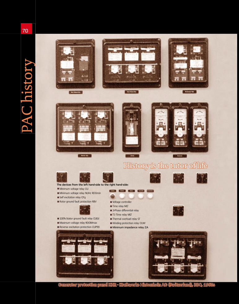
70 PAC history Generator protection panel KHR - Kraftwerke Hinterrhein AG (Switzerland), BBC, 1960s History is the tutor of life Minimum voltage relay CU Minimum voltage relay NUHc RDGmin Self excitation relay CFg Rotor ground fault protection RBV 100%-Stator ground fault relay CUEd Maximum voltage relay RDGMmax Reverse excitation protection CUP90 Voltage controller Time relay MLT 3-Phase differential relay T3 Time relay MLT Thermal overload relay ST Winding protection relay CUW Minimum impedance relay ZA The devices from the left hand-side to the right hand-side:
Transcript of PAC history - for the Protection, Automation and Control ... · S57 Rotor earth fault protection T...
70PA
C h
isto
ry
Generator protection panel KHR - Kraftwerke Hinterrhein AG (Switzerland), BBC, 1960s
History is the tutor of life
Minimum voltage relay CU
Minimum voltage relay NUHc RDGmin
Self excitation relay CFg
Rotor ground fault protection RBV
100%-Stator ground fault relay CUEd
Maximum voltage relay RDGMmax
Reverse excitation protection CUP90
Voltage controller
Time relay MLT
3-Phase differential relay
T3 Time relay MLT
Thermal overload relay ST
Winding protection relay CUW
Minimum impedance relay ZA
The devices from the left hand-side to the right hand-side:
PAC.SEPTEMBER.2011
71
by Walter Schossig, Germany
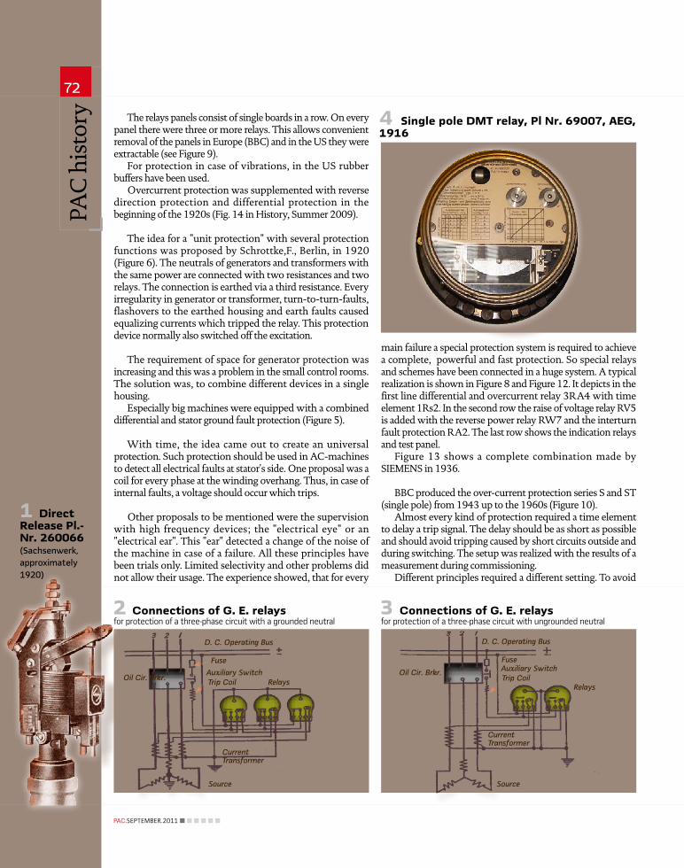
characteristic they are the oldest generator protection device. Small generators have been equipped with direct release (Figure 1).
Later, especially with big generators, indirect overcurrent release was used.
They are in use up to today in every generator- combined with differential relays and earth fault protection. If the neutral was earthed, three relays have been used (Figure 2); in case of isolated neutral two relays are sufficient (Figure 3).
The circle was used as a symbol bases on the round housings at this time (Figure 4).
The current transformer was between the generator plugs and the oil circuit breaker. In this circuit the relays protected against faults outside the generator and overload.
In case of faults in the generator there was no short-circuit current in this CT as long as no other generators operate in parallel. Later the CTs moved to the star point top to detect such faults too.
The relays were in the control room beside or under the measuring and control devices. It was the task of the operator to check them during operation. Figure 7 shows at the top the measuring devices, the control in the middle and the relays below.
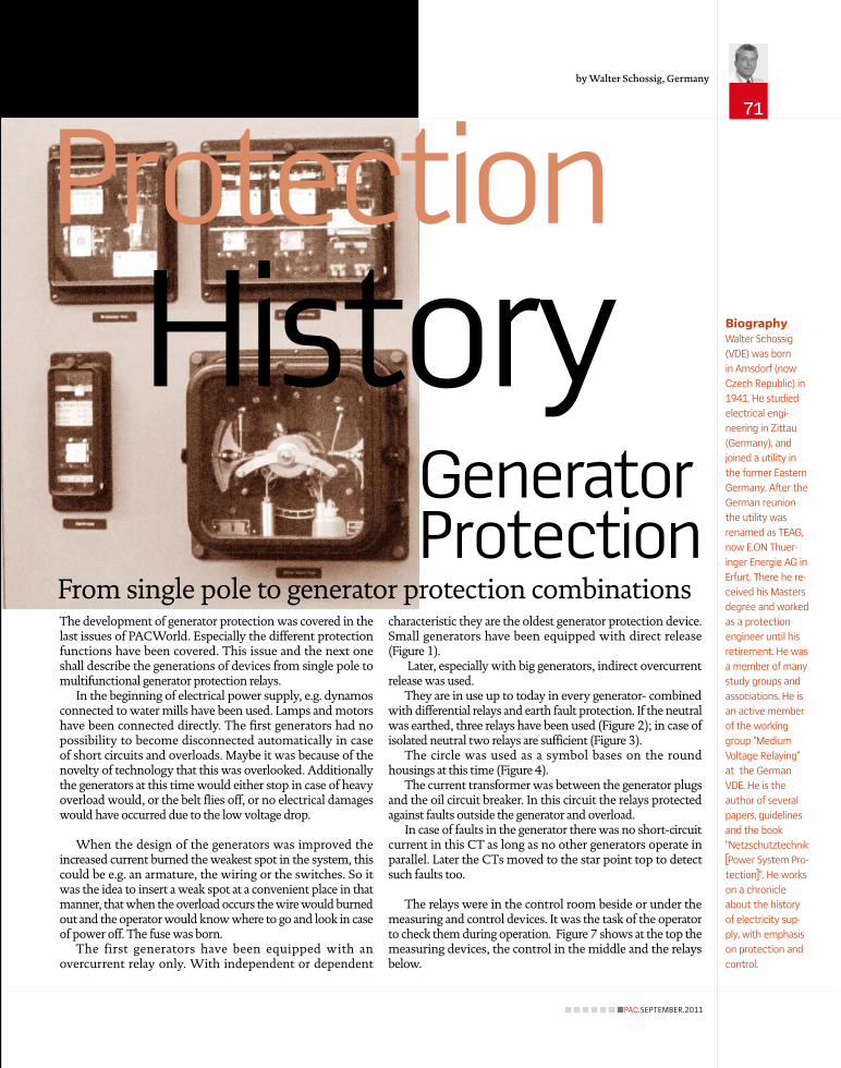
The development of generator protection was covered in the last issues of PACWorld. Especially the different protection functions have been covered. This issue and the next one shall describe the generations of devices from single pole to multifunctional generator protection relays.
In the beginning of electrical power supply, e.g. dynamos connected to water mills have been used. Lamps and motors have been connected directly. The first generators had no possibility to become disconnected automatically in case of short circuits and overloads. Maybe it was because of the novelty of technology that this was overlooked. Additionally the generators at this time would either stop in case of heavy overload would, or the belt flies off, or no electrical damages would have occurred due to the low voltage drop.
When the design of the generators was improved the increased current burned the weakest spot in the system, this could be e.g. an armature, the wiring or the switches. So it was the idea to insert a weak spot at a convenient place in that manner, that when the overload occurs the wire would burned out and the operator would know where to go and look in case of power off. The fuse was born.
The first generators have been equipped with an overcurrent relay only. With independent or dependent
BiographyWalter Schossig
(VDE) was born
in Arnsdorf (now
Czech Republic) in
1941. He studied
electrical engi-
neering in Zittau
(Germany), and
joined a utility in
the former Eastern
Germany. After the
German reunion
the utility was
renamed as TEAG,
now E.ON Thuer-
inger Energie AG in
Erfurt. There he re-
ceived his Masters
degree and worked
as a protection
engineer until his
retirement. He was
a member of many
study groups and
associations. He is
an active member
of the working
group “Medium
Voltage Relaying”
at the German
VDE. He is the
author of several
papers, guidelines
and the book
“Netzschutztechnik
[Power System Pro-
tection]”. He works
on a chronicle
about the history
of electricity sup-
ply, with emphasis
on protection and
control.
HistoryProtection
From single pole to generator protection combinations
Generator Protection
Fuse
Auxiliary Switch
D. C. Operating Bus
Trip CoilOil Cir. Brkr.
Current Transformer
Relays
Source
FuseAuxiliary Switch
D. C. Operating Bus
Trip CoilOil Cir. Brkr.
Current Transformer
Relays
Source
PAC
his
tory
72
PAC.SEPTEMBER.2011
The relays panels consist of single boards in a row. On every panel there were three or more relays. This allows convenient removal of the panels in Europe (BBC) and in the US they were extractable (see Figure 9).
For protection in case of vibrations, in the US rubber buffers have been used.
Overcurrent protection was supplemented with reverse direction protection and differential protection in the beginning of the 1920s (Fig. 14 in History, Summer 2009).
The idea for a "unit protection" with several protection functions was proposed by Schrottke,F., Berlin, in 1920 (Figure 6). The neutrals of generators and transformers with the same power are connected with two resistances and two relays. The connection is earthed via a third resistance. Every irregularity in generator or transformer, turn-to-turn-faults, flashovers to the earthed housing and earth faults caused equalizing currents which tripped the relay. This protection device normally also switched off the excitation.
The requirement of space for generator protection was increasing and this was a problem in the small control rooms. The solution was, to combine different devices in a single housing.
Especially big machines were equipped with a combined differential and stator ground fault protection (Figure 5).
With time, the idea came out to create an universal protection. Such protection should be used in AC-machines to detect all electrical faults at stator's side. One proposal was a coil for every phase at the winding overhang. Thus, in case of internal faults, a voltage should occur which trips.
Other proposals to be mentioned were the supervision with high frequency devices; the "electrical eye" or an "electrical ear". This "ear" detected a change of the noise of the machine in case of a failure. All these principles have been trials only. Limited selectivity and other problems did not allow their usage. The experience showed, that for every
main failure a special protection system is required to achieve a complete, powerful and fast protection. So special relays and schemes have been connected in a huge system. A typical realization is shown in Figure 8 and Figure 12. It depicts in the first line differential and overcurrent relay 3RA4 with time element 1Rs2. In the second row the raise of voltage relay RV5 is added with the reverse power relay RW7 and the interturn fault protection RA2. The last row shows the indication relays and test panel.
Figure 13 shows a complete combination made by SIEMENS in 1936.
BBC produced the over-current protection series S and ST (single pole) from 1943 up to the 1960s (Figure 10).
Almost every kind of protection required a time element to delay a trip signal. The delay should be as short as possible and should avoid tripping caused by short circuits outside and during switching. The setup was realized with the results of a measurement during commissioning.
Different principles required a different setting. To avoid
2 Connections of G. E. relays for protection of a three-phase circuit with a grounded neutral
4 Single pole DMT relay, Pl Nr. 69007, AEG, 1916
1 Direct Release Pl.- Nr. 260066 (Sachsenwerk,approximately 1920)
3 Connections of G. E. relays for protection of a three-phase circuit with ungrounded neutral

Door contacts
Test lamps
Measurement
Test resistance
Measurement
Indication
Auxiliary
Coils
Differential
Differential
Differential
Overcurrent
Overcurrent
Op. Excitation
Emergency
Time 0.25 s
Winding relay
PAC.SEPTEMBER.2011
73
a huge amount of time relays, Leopold Ferschl, ÖSSW, proposed a scheme in 1949. Very often three stages have been in use (differential 0.1 s; 0.2 s for winding and ground leakage, and 1...10 s for failures outside).
The generator protection of a 15, 000 kVA generator in a steam power station of RWE in 1939, consists of (starting from the left hand side: a time relay for earth fault protection; an earth fault relay, differential, IDMT and field shunting.
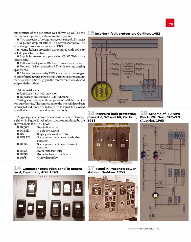
The first 40/50 MVA generator units in the power station Espenhain (Germany) were put into operation in 1940 (6/100 kV). Figure 14 shows Impedance protection SD14a, unbalance protection SM22, over current relay RSZ3g, overload indication RS3ek and in the last row differential protection for the generator with time element RZf; stator ground fault direction relays RERGZ, rotator ground fault protection REGL and reverse power protection RRGZ made by AEG. The wiring at the back is shown in Figure 11.
Oerlikon's interturn fault protection proposed in 1953 used a scheme (Figure 15 and Figure 16) that connects the star delta difference voltage and the phase voltage to a watt metric relay 5. With the detection of the involved phase the failure could be found easily.
A panel for a hydro power in Pracana (Portugal) for two Oerlikon-generators (8.000 kVA, 6.000 V, 1953) is shown in Figure 17. Cubicle 1 and 3 contains the excitation for generator 1 and 2; the cubicles 2 and 4 contain the measurement and protection devices for the generators.
5 RG21, SIEMENS generator-differential-and sta-tor ground fault protection
When a weak spot was inserted to burn out the wire when overload occurs - the fuse was born.
8 Scheme for generator protection (busbar operation), Siemens, 1936
7 Typical switchboard of protective relays, 1921
6 Generator protec-tion, Schrottke, 1920

18 generator/CB 20 de-exciation 1-2-3-4 differential 5-6 interturn protection 7-8 voltage relay 9-11 frame leakage protection
PAC
his
tory
74
PAC.SEPTEMBER.2011
AEG combined the single devices RS1 with a transistor time element and rotor ground fault protection REGL and a new generator differential relay to the new combination RKG1 in 1960 (Figure 20).
To reduce the effort for wiring and to limit the space requirements, the VEM in Eastern Germany tried to collect all functions in a single device in 1963. The generator protection GSE for synchronous generators (1...63 MVA) combined the single devices made by EAW in a housing 985 mm x 380 mm x 175 mm (Figure 19).
Figure 22 presents a protection concept for huge generators in unit connection developed by BBC in the 1960s. The components are as follows:
S57 Rotor earth fault protection T Differential relays (3-phase) S Overcurrent relay ST Thermal relay CH90c Reverse power relay +MLTS Time relay CUH90c 3-phase- stator-groundfault relays
The Austrian heating station Graz (1963, 2x 50-MVA, 10/110 kV) was equipped with BBC relays as can be seen in Figure 18:
Two single pole IDMT relays S1 in phases R and T; a thermal relay ST in the return conductor of the current transformer. The thermal relay was set according to the nominal current of the generator. The range for the temperature was between 50°C und 120°C. The current
All components in Figure 17 are as follows : 1; 3 Thermal relays BiTs 2 Overcurrent relays MIZs 4…6 Differential-Relays DIhas 7 Rotor-ground-fault-protection DUhs 8 Stator-ground-fault DIhs 9 Temperature 10 Maximum voltage relays DUhs 11 Time relays KZs
12 Generator protection, Siemens, 1936 (busbar operation)
11 Wiring in Espenhain, 1940 Almost every kind of protection required a time
element to delay a trip signal.
13 Complete combination, Siemens, 1936
9Extractable panels (US) (around 1950)
10 BBC, 1943(Thermal over current relay ST)
PAC.SEPTEMBER.2011
75
temperature of the generator was shown as well as the maximum temperature with a non-return pointer
Two stage raise of voltage relays, consisting of a first stage RBGM, pickup-drop-off-ratio of 97.5 % with short delay. The second stage consists of an undelayed RBG
Frame-leakage protection was required with 100% to include generator's neutral
3-pole interturn fault protection CUW. This was a Ferraris relay
Differential relay was a DMS with inrush-stabilization Rotor-earth-fault protection RBVwith a setting starting
up at 50 mA The reverse-power relay CH90c operated in two stages.
In case of small reverse powers (e.g. during synchronization) the delay was 5 s. So the guy in the control center could avoid a trip with the turbine
Additional devices: Unbalance-relay with indication Impedance protection RK1Z4a (SIEMENS)
Testing was possible while in operation and if the machine was out of service. The connections to the trip coils have been interrupted and connected to lamps. To test switches allowed it, to disable a part of protection functions only.
A typical generator protection scheme in Eastern Germany is shown in Figure 21. All relays have been produced by the only vendor in the GDR- EAW:
RQS4T1 3-pole differential RSZ3f2 3-pole overcurrent RSf5 Single phase overload relay RERZG Stator ground fault protection busbar
operation REG4 Stator ground fault protection unit
operation REG5 Rotor earth fault relay REG6 Rotor double earth fault relay Ruf5 Overvoltage relay
15 Interturn fault protection, Oerlikon, 1953
14 Generator protection panel in genera-tor 4, Espenhain, AEG, 1940
18 Scheme of 50-MVA- Block, KW Graz, STEWAG (Austria), 1963
16 Interturn fault protection phase R-S, S-T and T-R, Oerlikon, 1953
17 Panel in Pracana's power station, Oerlikon, 1953

CUH 90cCH 90c+MLTs
ST ST STSSSS 57 T
G
S57 Rotor earth fault protection CUH90c 3-phase- stator-groundfault T Differential relays (3-phase) CH90c Reverse power relay
ST - Thermal relay | S - Overcurrent | +MLTS - Time relay
PAC
his
tory
76
PAC.SEPTEMBER.2011
21 Unit protection, 20-MVA-generator, EAW, 1975
20 RKG1, AEG, 1960
23 Generator protection, hydro - power - station Wisenta, EAW, approximately 1970
To install the single devices for such generators a panel 2,20 m x 0,8 m was required (Figure 23). The 500-MW-units used in GDR beginning in 1974 different vendors have been used:
Overcurrent protection RSZ3f2, stator ground fault REG4 and differential RQS4T (EAW). Loss of excitation protection D20, distance protection D21 and frequency relay F13 were produced by ZPA (CSSR). Unbalance relay RTF7 and rotor double earth fault protection KSR2 came from the Soviet Union. For huge generators the protection was doubled (Backup protection with same settings as main protection, also for earth-fault and unbalance protection). The batteries have been doubled as well as tripping coils of the circuit breakers, de-excitation-switches and so on. 12 panels were used.
Up to the 1950s electromechanical measuring systems have been the standard - moving coil, soft iron, bimetals and electro-dynamical measuring element. In the US Ferraris measuring systems were very popular. Passive elements (capacitors, resistances, reactors).
Electronic elements, e.g. simple diodes were not used. This changed in the 1960s and will be discussed in the next issue.
[email protected] www.walter-schossig.de
22 Protection scheme for unit connection, BBC, 1960s
19 VEM/ SAVO, 1963 (protective equipment for generators GSE)