PAC ControlLogix Systems Spares - Isaac Newton …eng/ops/spares/PAC_SparesList.pdf · 5=...
17
PAC ControlLogix Systems Spares
Transcript of PAC ControlLogix Systems Spares - Isaac Newton …eng/ops/spares/PAC_SparesList.pdf · 5=...
PAC ControlLogix Systems
Spares
PAC’s Spares Modules Date: 12-Dic-2014
Carlos Martin 12/12/14 Page 2 of 17
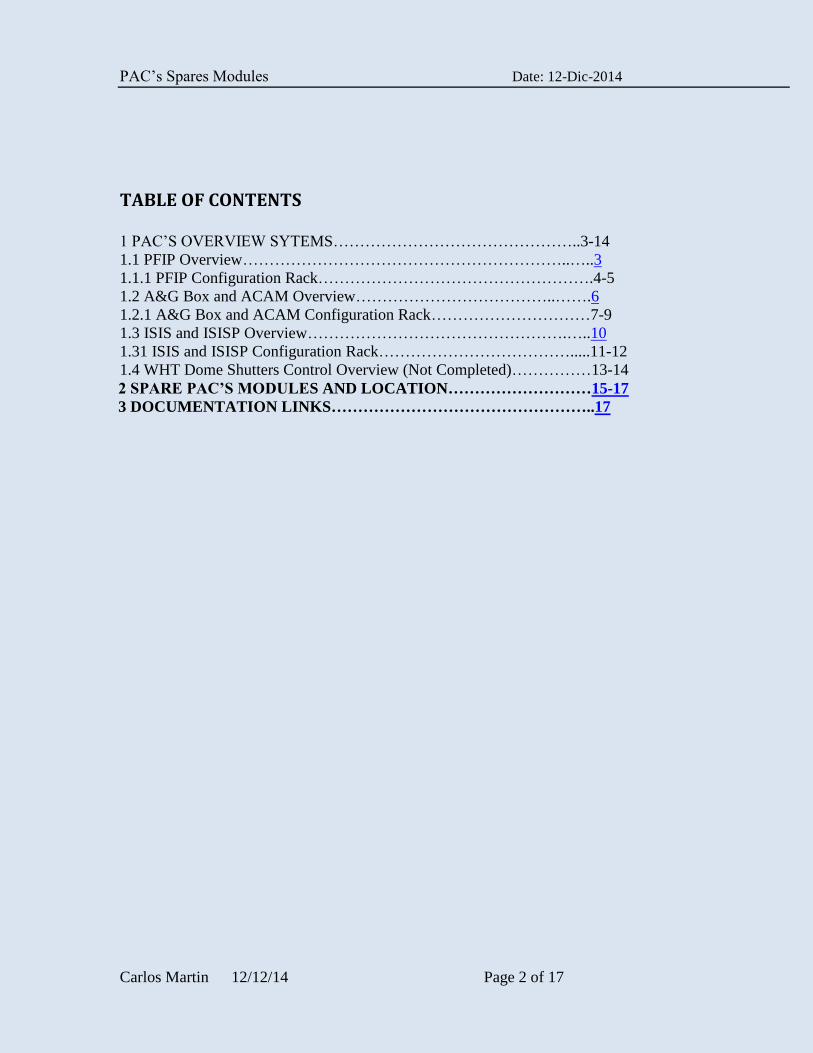
TABLE OF CONTENTS
1 PAC’S OVERVIEW SYTEMS………………………………………..3-14
1.1 PFIP Overview……………………………………………………..…..3
1.1.1 PFIP Configuration Rack…………………………………………….4-5
1.2 A&G Box and ACAM Overview………………………………..…….6
1.2.1 A&G Box and ACAM Configuration Rack…………………………7-9
1.3 ISIS and ISISP Overview………………………………………….…..10
1.31 ISIS and ISISP Configuration Rack……………………………….....11-12
1.4 WHT Dome Shutters Control Overview (Not Completed)……………13-14
2 SPARE PAC’S MODULES AND LOCATION………………………15-17
3 DOCUMENTATION LINKS…………………………………………..17
PAC’s Spares Modules Date: 12-Dic-2014
Carlos Martin 12/12/14 Page 3 of 17
1 PAC’S OVERVIEW SYTEMS
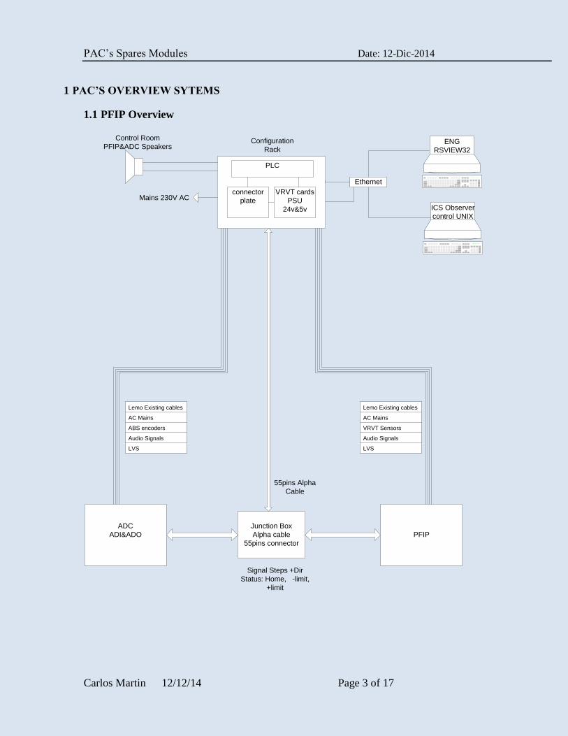
1.1 PFIP Overview
PLC
connector
plate
VRVT cards
PSU
24v&5v
Control Room
PFIP&ADC Speakers
Mains 230V AC
Ethernet
Configuration
Rack
ADC
ADI&ADO PFIP
Junction Box
Alpha cable
55pins connector
Signal Steps +Dir
Status: Home, -limit,
+limit
Lemo Existing cables
AC Mains
VRVT Sensors
Audio Signals
LVS
Lemo Existing cables
AC Mains
ABS encoders
Audio Signals
LVS
55pins Alpha
Cable
ENG
RSVIEW32
ICS Observer
control UNIX
PAC’s Spares Modules Date: 12-Dic-2014
Carlos Martin 12/12/14 Page 4 of 17
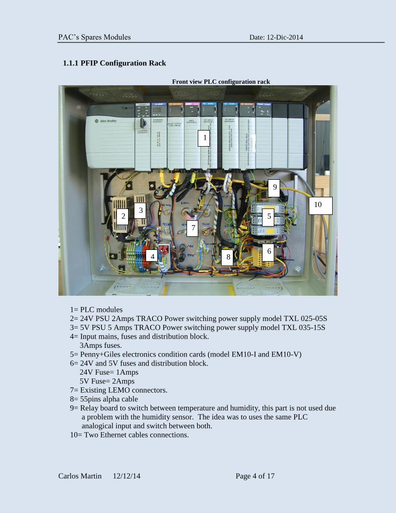
1.1.1 PFIP Configuration Rack
Front view PLC configuration rack
1= PLC modules
2= 24V PSU 2Amps TRACO Power switching power supply model TXL 025-05S
3= 5V PSU 5 Amps TRACO Power switching power supply model TXL 035-15S
4= Input mains, fuses and distribution block.
3Amps fuses.
5= Penny+Giles electronics condition cards (model EM10-I and EM10-V)
6= 24V and 5V fuses and distribution block.
24V Fuse= 1Amps
5V Fuse= 2Amps
7= Existing LEMO connectors.
8= 55pins alpha cable
9= Relay board to switch between temperature and humidity, this part is not used due
a problem with the humidity sensor. The idea was to uses the same PLC
analogical input and switch between both.
10= Two Ethernet cables connections.
2 3
5
4 6
1
7
8
9
10
PAC’s Spares Modules Date: 12-Dic-2014
Carlos Martin 12/12/14 Page 5 of 17
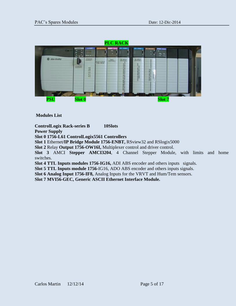
PLC RACK
PSU Slot 0 Slot 7
Modules List
ControlLogix Rack-series B 10Slots
Power Supply
Slot 0 1756-L61 ControlLogix5561 Controllers Slot 1 Ethernet/IP Bridge Module 1756-ENBT, RSview32 and RSlogix5000
Slot 2 Relay Output 1756-OW16I, Multiplexer control and driver control.
Slot 3 AMCI Stepper AMCI3204, 4 Channel Stepper Module, with limits and home
switches.
Slot 4 TTL Inputs modules 1756-IG16, ADI ABS encoder and others inputs signals.
Slot 5 TTL Inputs module 1756-IG16, ADO ABS encoder and others inputs signals.
Slot 6 Analog Input 1756-IF8, Analog Inputs for the VRVT and Hum/Tem sensors.
Slot 7 MVI56-GEC, Generic ASCII Ethernet Interface Module.

PAC’s Spares Modules Date: 12-Dic-2014
Carlos Martin 12/12/14 Page 6 of 17
1.2 A&G Box and ACAM Overview
A&G Box Junction Box
A&G Box
INSTRUMENT
A B C D
SM
DB
ox
A P
L1
SM
DB
ox
B P
L2
SM
DB
ox
C P
L3
SM
DB
ox
D P
L4
Sig
na
ls P
L5
Stepper Power Amplifier Rack
+
Elect. Signal Conditioning Card
+
PSU 24V and 5V Sensors & Enc.
SK
6
SK
7
SK
8
SK
9
SK
10
PSU 24V
Motors
PSU 48V
MotorsSK20
SK21
SK19To Spare Motor
SK18To Spare Motor
SK
16
SK
15
SK
14
SK
13
SK
12
SK
11
SK
17
SK
22
SK
23
SK
24
SK
25
SK
26
SK
27
SK
28
Comparison
Lamps
SK
29
D’ 25 Pins
Chassis Local
PLC#1Chassis Remote
PLC#2
SK
30
SK
31
SK
32
SK
33
AF
O L
VD
T
TF
O L
VD
T
AG
R L
VD
T
AG
T A
BS
En
co
de
r
AFO LVDT PL127
AGR LVDT PL130
TFO LVDT PL110
AGT ABS Encoder PL122
Comp. Lamps Signal
Conditioning Card
Monitor PSU’s Signal
Conditioning CardSK
5
SK
3
SK
1
ACAM
See ACAM Code drawing:SQ.026
PS
U’s
Sig
na
ls
Sig
na
ls
Sig
na
ls
Sig
na
ls
Sig
na
ls
PS
U’s
Created By: Carlos Martin
Date: 28/04/2010
Title: A&G Box General Block Diagram
Code drawing: SQ.042
PAC’s Spares Modules Date: 12-Dic-2014
Carlos Martin 12/12/14 Page 7 of 17
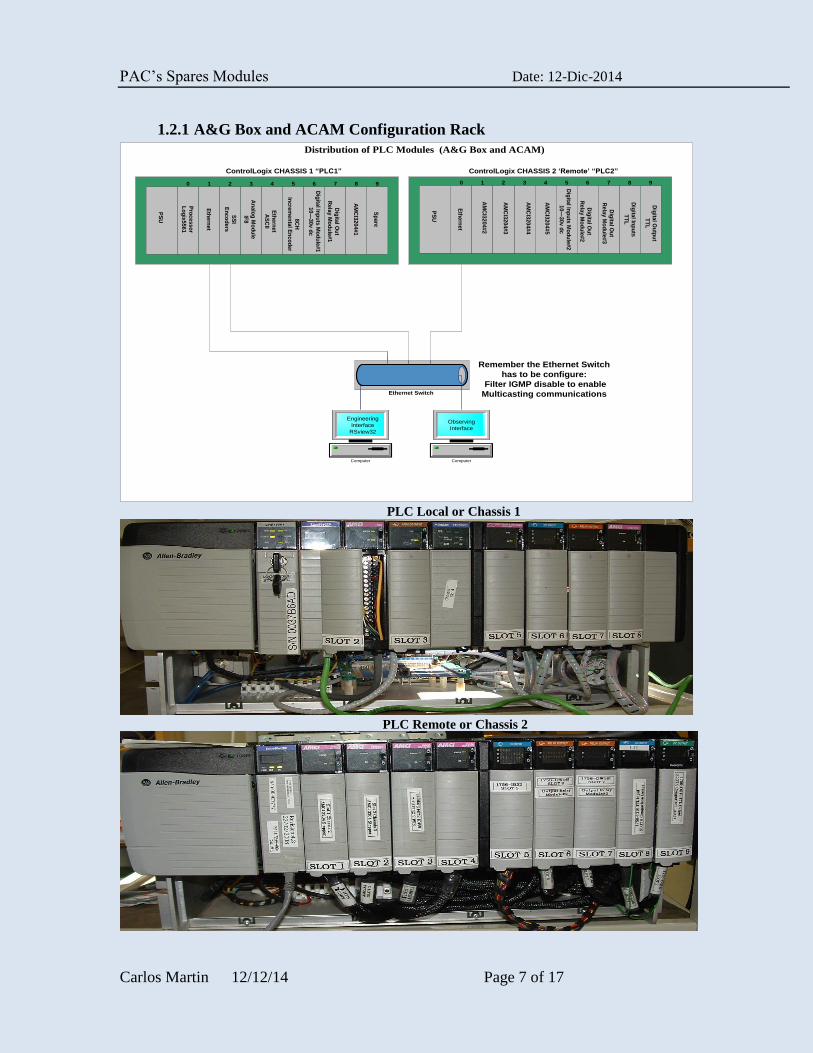
1.2.1 A&G Box and ACAM Configuration Rack
Pro
ce
ss
or
Lo
gix
55
61
Eth
ern
et
PS
U
SS
I
En
co
de
rs
An
alo
g M
od
ule
IF8 8C
H
Inc
rem
en
tal E
nc
od
er
0 1 2 3 4 5 6 7 8 9D
igita
l Inp
uts
TT
L
Dig
ital O
utp
ut
TT
L
Sp
are
AM
CI3
20
4#
1
AM
CI3
20
4#
2
PS
U
AM
CI3
20
4#4
AM
CI3
20
4#3
AM
CI3
20
4#5
0 1 2 3 4 5 6 7 8 9
Dig
ital In
pu
ts M
od
ule
#1
10
—3
0v
dc
Dig
ital O
ut
Re
lay
Mo
du
le#
1
Dig
ital O
ut
Re
lay
Mo
du
le#
2
ControlLogix CHASSIS 1 “PLC1” ControlLogix CHASSIS 2 ‘Remote’ “PLC2”
Eth
ern
et
Dig
ital In
pu
ts M
od
ule
#2
10—
30
v d
c
Distribution of PLC Modules (A&G Box and ACAM)
Ethernet Switch
Computer Computer
Engineering
Interface
RSview32
Observing
Interface
Eth
ern
et
AS
CII
Dig
ital O
ut
Re
lay
Mo
du
le#
3
Remember the Ethernet Switch
has to be configure:
Filter IGMP disable to enable
Multicasting communications
PLC Local or Chassis 1
PLC Remote or Chassis 2
PAC’s Spares Modules Date: 12-Dic-2014
Carlos Martin 12/12/14 Page 8 of 17
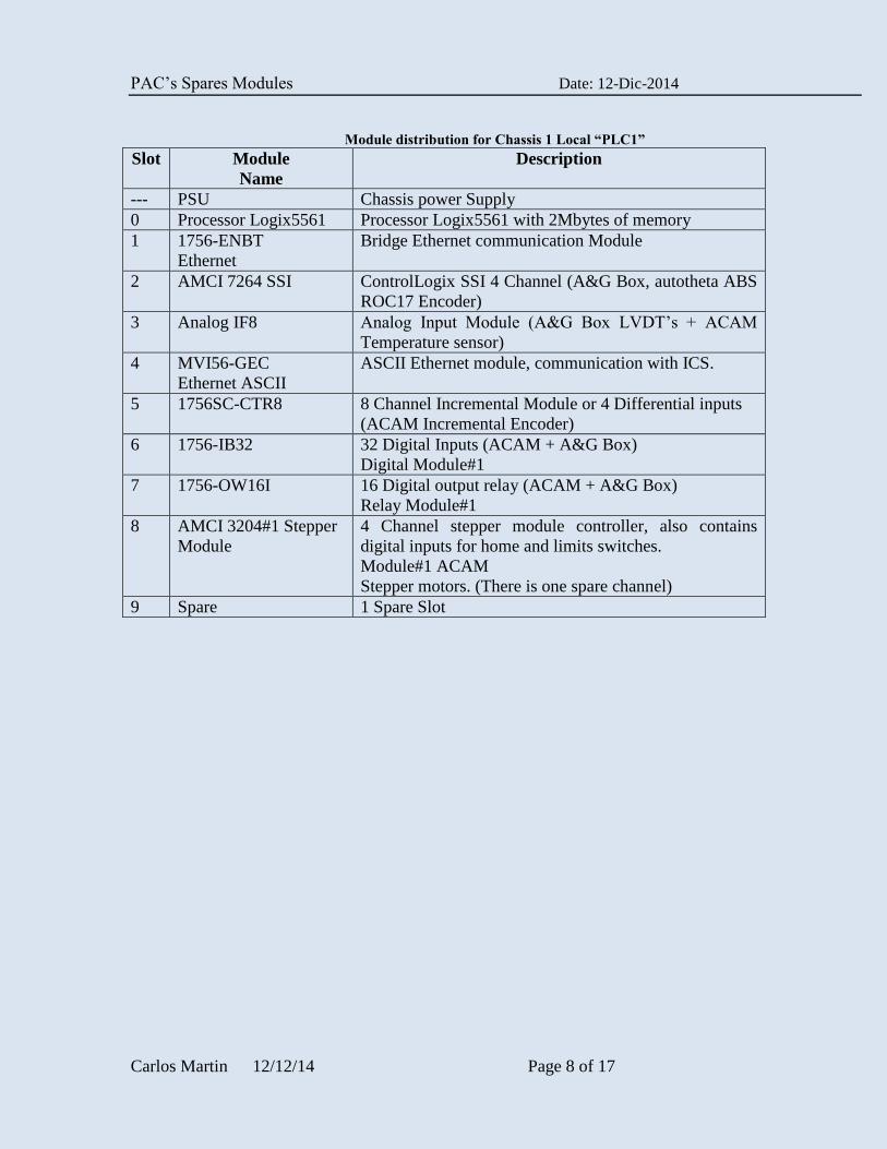
Module distribution for Chassis 1 Local “PLC1”
Slot Module
Name
Description
--- PSU Chassis power Supply
0 Processor Logix5561 Processor Logix5561 with 2Mbytes of memory
1 1756-ENBT
Ethernet
Bridge Ethernet communication Module
2 AMCI 7264 SSI ControlLogix SSI 4 Channel (A&G Box, autotheta ABS
ROC17 Encoder)
3 Analog IF8 Analog Input Module (A&G Box LVDT’s + ACAM
Temperature sensor)
4 MVI56-GEC
Ethernet ASCII
ASCII Ethernet module, communication with ICS.
5 1756SC-CTR8 8 Channel Incremental Module or 4 Differential inputs
(ACAM Incremental Encoder)
6 1756-IB32 32 Digital Inputs (ACAM + A&G Box)
Digital Module#1
7 1756-OW16I 16 Digital output relay (ACAM + A&G Box)
Relay Module#1
8 AMCI 3204#1 Stepper
Module
4 Channel stepper module controller, also contains
digital inputs for home and limits switches.
Module#1 ACAM
Stepper motors. (There is one spare channel)
9 Spare 1 Spare Slot
PAC’s Spares Modules Date: 12-Dic-2014
Carlos Martin 12/12/14 Page 9 of 17
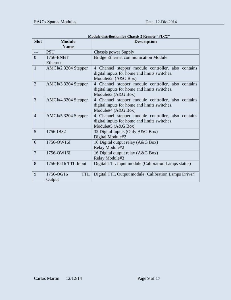
Module distribution for Chassis 2 Remote “PLC2”
Slot Module
Name
Description
--- PSU Chassis power Supply
0 1756-ENBT
Ethernet
Bridge Ethernet communication Module
1 AMCI#2 3204 Stepper 4 Channel stepper module controller, also contains
digital inputs for home and limits switches.
Module#2 (A&G Box)
2 AMCI#3 3204 Stepper 4 Channel stepper module controller, also contains
digital inputs for home and limits switches.
Module#3 (A&G Box)
3 AMCI#4 3204 Stepper 4 Channel stepper module controller, also contains
digital inputs for home and limits switches.
Module#4 (A&G Box)
4 AMCI#5 3204 Stepper 4 Channel stepper module controller, also contains
digital inputs for home and limits switches.
Module#5 (A&G Box)
5 1756-IB32 32 Digital Inputs (Only A&G Box)
Digital Module#2
6 1756-OW16I 16 Digital output relay (A&G Box)
Relay Module#2
7 1756-OW16I 16 Digital output relay (A&G Box)
Relay Module#3
8 1756-IG16 TTL Input Digital TTL Input module (Calibration Lamps status)
9 1756-OG16 TTL
Output
Digital TTL Output module (Calibration Lamps Driver)
PAC’s Spares Modules Date: 12-Dic-2014
Carlos Martin 12/12/14 Page 10 of 17
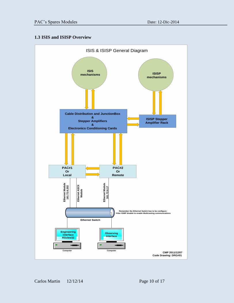
1.3 ISIS and ISISP Overview
ISISP
mechanisms
ISIS
mechanisms
Cable Distribution and JunctionBox
&
Stepper Amplifiers
&
Electronics Conditioning Cards
ISISP Stepper
Amplifier Rack
PAC#2
Or
Remote
PAC#1
Or
Local
Computer Computer
Engineering
Interface
RSview32
Observing
Interface
Ethernet Switch
Eth
ern
et
Mo
du
le
16
1.7
2.6
.20
2
Eth
ern
et
AS
CII
Mo
du
le
Eth
ern
et
Mo
du
le
16
1.7
2.6
.17
ISIS & ISISP General Diagram
CMP 2011/12/07
Code Drawing: DRG#01
Remember the Ethernet Switch has to be configure:
Filter IGMP disable to enable Multicasting communications
PAC’s Spares Modules Date: 12-Dic-2014
Carlos Martin 12/12/14 Page 11 of 17
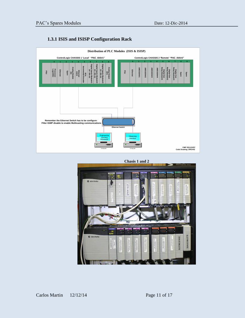
1.3.1 ISIS and ISISP Configuration Rack
Pro
ce
ss
or
Lo
gix
55
61
Eth
ern
et
PS
U
Sp
are
An
alo
g M
od
ule
IF8 8C
H
Inc
rem
en
tal E
nc
od
er
0 1 2 3 4 5 6 7 8 9
An
alo
g O
utp
ut
OF
4
AM
CI3
20
4#
1
PS
U
AM
CI3
20
4#
3
AM
CI3
20
4#
2
AM
CI3
20
4#
4
0 1 2 3 4 5 6 7 8 9
Dig
ital In
pu
ts M
od
ule
#1
10
—3
0v
dc
Dig
ital O
ut
Re
lay
Mo
du
le#
2
ControlLogix CHASSIS 1 ‘Local’ “PAC_ISIS#1” ControlLogix CHASSIS 2 ‘Remote’ “PAC_ISIS#2”
Eth
ern
et
Distribution of PLC Modules (ISIS & ISISP)
Ethernet Switch
Computer Computer
Engineering
Interface
RSview32
Observing
Interface
Eth
ern
et
AS
CII
Dig
ital O
ut
Re
lay
Mo
du
le#
3
Remember the Ethernet Switch has to be configure:
Filter IGMP disable to enable Multicasting communications
Dig
ital In
pu
ts M
od
ule
#2
10
—3
0v
dc
Dig
ital In
pu
ts M
od
ule
#3
10
—3
0v
dc
Dig
ital O
ut
Re
lay
Mo
du
le#
1
Sp
are
Sp
are
CMP 2011/12/07
Code Drawing: DRG#02
Chasis 1 and 2
PAC’s Spares Modules Date: 12-Dic-2014
Carlos Martin 12/12/14 Page 12 of 17
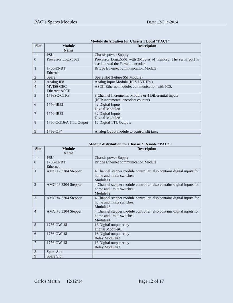
Module distribution for Chassis 1 Local “PAC1”
Slot Module
Name
Description
--- PSU Chassis power Supply
0 Processor Logix5561 Processor Logix5561 with 2Mbytes of memory, The serial port is
used to read the Ferranti encoders
1 1756-ENBT
Ethernet
Bridge Ethernet communication Module
2 Spare Spare slot (Future SSI Module)
3 Analog IF8 Analog Input Module (ISIS LVDT’s )
4 MVI56-GEC
Ethernet ASCII
ASCII Ethernet module, communication with ICS.
5 1756SC-CTR8 8 Channel Incremental Module or 4 Differential inputs
(ISIP incremental encoders counter)
6 1756-IB32 32 Digital Inputs
Digital Module#1
7 1756-IB32 32 Digital Inputs
Digital Module#1
8 1756-OG16/A TTL Output
16 Digital TTL Outputs
9 1756-OF4 Analog Ouput module to control slit jaws
Module distribution for Chassis 2 Remote “PAC2”
Slot Module
Name
Description
--- PSU Chassis power Supply
0 1756-ENBT
Ethernet
Bridge Ethernet communication Module
1 AMCI#2 3204 Stepper 4 Channel stepper module controller, also contains digital inputs for
home and limits switches.
Module#1
2 AMCI#3 3204 Stepper 4 Channel stepper module controller, also contains digital inputs for
home and limits switches.
Module#2
3 AMCI#4 3204 Stepper 4 Channel stepper module controller, also contains digital inputs for
home and limits switches.
Module#3
4 AMCI#5 3204 Stepper 4 Channel stepper module controller, also contains digital inputs for
home and limits switches.
Module#4
5 1756-OW16I 16 Digital output relay
Digital Module#1
6 1756-OW16I 16 Digital output relay
Relay Module#2
7 1756-OW16I 16 Digital output relay
Relay Module#3
8 Spare Slot
9 Spare Slot
PAC’s Spares Modules Date: 12-Dic-2014
Carlos Martin 12/12/14 Page 13 of 17
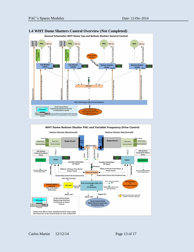
1.4 WHT Dome Shutters Control Overview (Not Completed)
Top ShutterVFD#1
ABS Enc.M#1
Bra
ke#1
Bra
ke#2
Top ShutterVFD#2
ABS Enc.M#2
Bra
ke#1
Bra
ke#2
ABS Enc.M#1 ABS Enc.M#2
Bottom ShutterVFD#2
Bottom ShutterVFD#1
Ethernet
PAC ControlLogix 5561 CPU I/O Modules
Master Slave Master Slave
Po
siti
on
Vel
oci
ty F
eed
bac
k
Po
siti
on
Vel
oci
ty F
eed
bac
k
Po
siti
on
Vel
oci
ty F
eed
bac
k
Po
siti
on
Vel
oci
ty F
eed
bac
k
General Schematics WHT Dome Top and Bottom Shutters General Control
Dig
ital
Ou
t C
on
tro
l Lik
e Em
erge
ncy
Sto
p
Dig
ital
Ou
t C
on
tro
l
Dig
ital
Ou
t C
on
tro
l
Dig
ital
Ou
t C
on
tro
l Lik
e Em
erge
ncy
Sto
p
D. O
ut
Ctr
l Lik
e Em
erge
ncy
Sto
p
D. O
ut
Ctr
l Lik
e Em
erge
ncy
Sto
p
Temp & Hum Sensors
Analog Module
Local Control PanelMode Operate Select Key
Emergency Stop etc.
At the Control RoomEngineering Interface for Remote
or Status/Alarm Control
Computer
RSView32
MonitorHIM
MonitorHIM
MonitorHIM
MonitorHIM
Status from Mirror Cover Sent/Received by msg’s usingthe Dome PLC at the Control Room or cmd. using PLCIO
Au
xilia
ry M
oto
r#1
Bra
ke#3
Au
xilia
ry M
oto
r#2
Bra
ke#3
ABS Encoder
Micro Drive
Electrical Motor
Brake Wheel
Gear Box
Bottom Shutter Machinery#1
Main Drive
Electrical Motor
Rope Drum
VFD#1
PAC ControlLogix 5561 CPU And
I/O Modules
Ethernet Switch
3~ Phases
3~ Phases
VFD#2Encoder Clock/Data
SSI Signal Encoder Clock/Data
SSI Signal
Shutter Limits Switches
Temperature &
Humidity Sensors
Rise and LowerMain Drive
PSU 24VDigital Input
Monitor
Micro Drive
Electrical Motor
Brake Wheel
Gear Box
Bottom Shutter Machinery#2
Main Drive
Electrical Motor
Rope Drum
PSU
24V
PSU
24V
Mains UPS
Mains UPS
Mains 3 Phases from Dome Power Panel
PSU 24V Terminal
WireLess
Mains 3 Phases from Dome Power Panel
Reset Input to PAC
Reset Input to PAC
To Enc. Electronics Reset 1&2
Brake Resistor 1 Brake Resistor 2
1 2
Thermal Overload RelayTo PAC Digital Input
Thermal Overload RelayTo PAC Digital Input
Digital Input 1&2 Thermal Overload Relay
Digital Inputs
Analog Inputs
Output Relay Control Like Emergency StopOutput Relay Control Like Emergency Stop
Local Control PanelMode Operate Select Key
Emergency Stop
WHT Dome Bottom Shutter PAC and Variable Frequency Drive Control
Digital I/O
MonitorHIM
MonitorHIM
Old SystemControl for Micro
Drive
Old SystemControl for Micro
Drive
Warning Sound Alarm when the Shutter is Closing o Opening
At the Control RoomEngineering Interface for Remote or Status
Control
Computer
RSView32
Status from Mirror Cover Sent/Received by msg’s usingthe Dome PLC at the Control Room or cmd. using PLCIO
PAC’s Spares Modules Date: 12-Dic-2014
Carlos Martin 12/12/14 Page 14 of 17
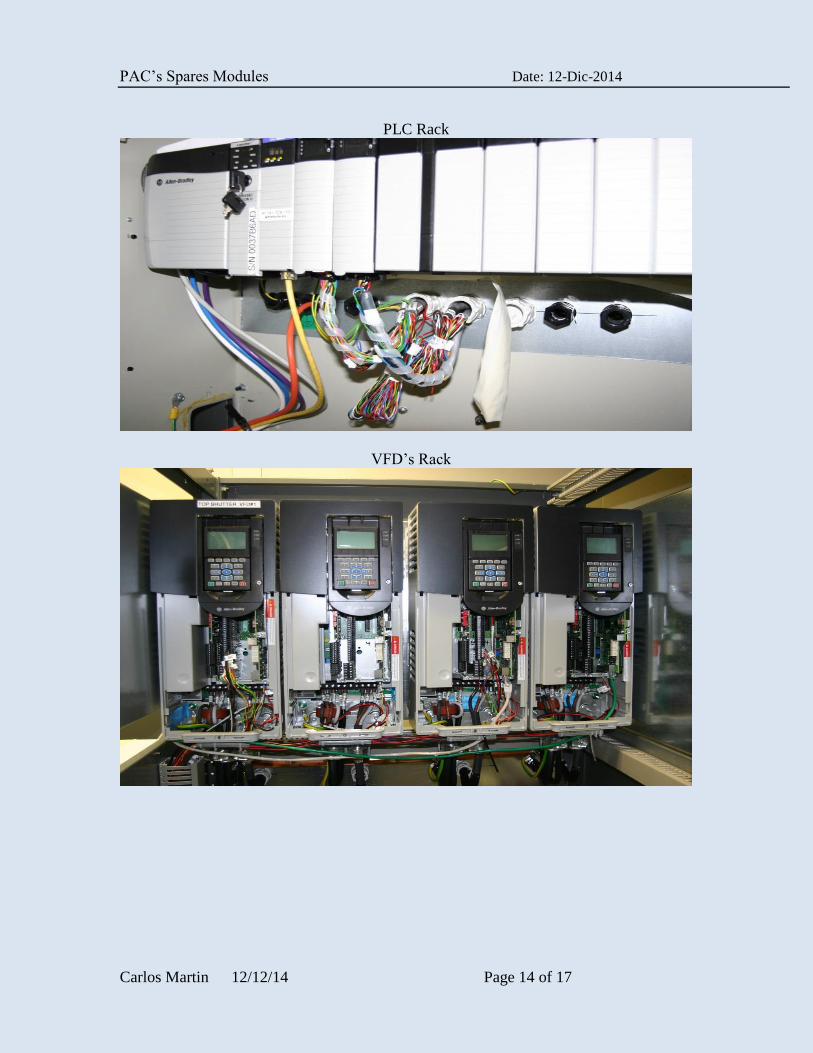
PLC Rack
VFD’s Rack
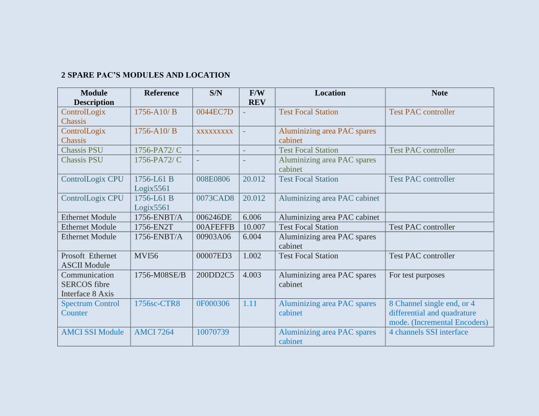
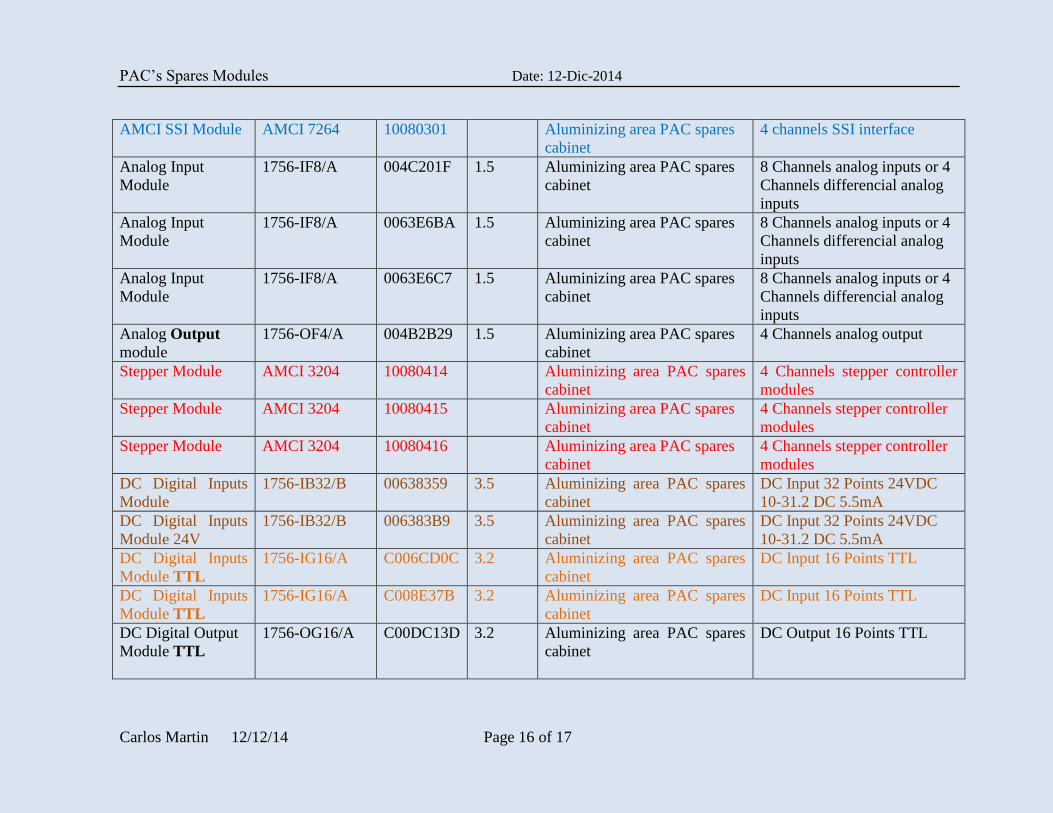
2 SPARE PAC’S MODULES AND LOCATION
Module
Description
Reference S/N F/W
REV
Location Note
ControlLogix
Chassis
1756-A10/ B 0044EC7D - Test Focal Station
Test PAC controller
ControlLogix
Chassis
1756-A10/ B xxxxxxxxx - Aluminizing area PAC spares
cabinet
Chassis PSU 1756-PA72/ C - - Test Focal Station Test PAC controller
Chassis PSU 1756-PA72/ C - - Aluminizing area PAC spares
cabinet
ControlLogix CPU 1756-L61 B
Logix5561
008E0806 20.012 Test Focal Station
Test PAC controller
ControlLogix CPU 1756-L61 B
Logix5561
0073CAD8 20.012 Aluminizing area PAC cabinet
Ethernet Module 1756-ENBT/A 006246DE 6.006 Aluminizing area PAC cabinet
Ethernet Module 1756-EN2T 00AFEFFB 10.007 Test Focal Station Test PAC controller
Ethernet Module 1756-ENBT/A 00903A06 6.004 Aluminizing area PAC spares
cabinet
Prosoft Ethernet
ASCII Module
MVI56 00007ED3 1.002 Test Focal Station Test PAC controller
Communication
SERCOS fibre
Interface 8 Axis
1756-M08SE/B 200DD2C5 4.003 Aluminizing area PAC spares
cabinet
For test purposes
Spectrum Control
Counter
1756sc-CTR8
0F000306 1.11 Aluminizing area PAC spares
cabinet
8 Channel single end, or 4
differential and quadrature
mode. (Incremental Encoders)
AMCI SSI Module AMCI 7264 10070739 Aluminizing area PAC spares
cabinet
4 channels SSI interface
PAC’s Spares Modules Date: 12-Dic-2014
Carlos Martin 12/12/14 Page 16 of 17
AMCI SSI Module AMCI 7264 10080301 Aluminizing area PAC spares
cabinet
4 channels SSI interface
Analog Input
Module
1756-IF8/A 004C201F 1.5 Aluminizing area PAC spares
cabinet
8 Channels analog inputs or 4
Channels differencial analog
inputs
Analog Input
Module
1756-IF8/A 0063E6BA 1.5 Aluminizing area PAC spares
cabinet
8 Channels analog inputs or 4
Channels differencial analog
inputs
Analog Input
Module
1756-IF8/A 0063E6C7 1.5 Aluminizing area PAC spares
cabinet
8 Channels analog inputs or 4
Channels differencial analog
inputs
Analog Output
module
1756-OF4/A 004B2B29 1.5 Aluminizing area PAC spares
cabinet
4 Channels analog output
Stepper Module AMCI 3204 10080414 Aluminizing area PAC spares
cabinet
4 Channels stepper controller
modules
Stepper Module AMCI 3204 10080415 Aluminizing area PAC spares
cabinet
4 Channels stepper controller
modules
Stepper Module AMCI 3204 10080416 Aluminizing area PAC spares
cabinet
4 Channels stepper controller
modules
DC Digital Inputs
Module
1756-IB32/B 00638359 3.5 Aluminizing area PAC spares
cabinet
DC Input 32 Points 24VDC
10-31.2 DC 5.5mA
DC Digital Inputs
Module 24V
1756-IB32/B 006383B9 3.5 Aluminizing area PAC spares
cabinet
DC Input 32 Points 24VDC
10-31.2 DC 5.5mA
DC Digital Inputs
Module TTL
1756-IG16/A C006CD0C 3.2 Aluminizing area PAC spares
cabinet
DC Input 16 Points TTL
DC Digital Inputs
Module TTL
1756-IG16/A C008E37B 3.2 Aluminizing area PAC spares
cabinet
DC Input 16 Points TTL
DC Digital Output
Module TTL
1756-OG16/A C00DC13D 3.2 Aluminizing area PAC spares
cabinet
DC Output 16 Points TTL
PAC’s Spares Modules Date: 12-Dic-2014
Carlos Martin 12/12/14 Page 17 of 17
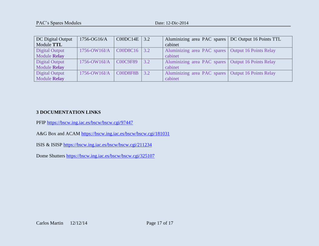
DC Digital Output
Module TTL
1756-OG16/A C00DC14E 3.2 Aluminizing area PAC spares
cabinet
DC Output 16 Points TTL
Digital Output
Module Relay
1756-OW16I/A C00D8C16 3.2 Aluminizing area PAC spares
cabinet
Output 16 Points Relay
Digital Output
Module Relay
1756-OW16I/A C00C9F89 3.2 Aluminizing area PAC spares
cabinet
Output 16 Points Relay
Digital Output
Module Relay
1756-OW16I/A C00D8F8B 3.2 Aluminizing area PAC spares
cabinet
Output 16 Points Relay
3 DOCUMENTATION LINKS
PFIP https://bscw.ing.iac.es/bscw/bscw.cgi/97447
A&G Box and ACAM https://bscw.ing.iac.es/bscw/bscw.cgi/181031
ISIS & ISISP https://bscw.ing.iac.es/bscw/bscw.cgi/211234
Dome Shutters https://bscw.ing.iac.es/bscw/bscw.cgi/325107