PAC BT / PAC BT Solar Air-water heat pump in two sections...
36
AIR CONDITIONING & HEATING PAC BT / PAC BT Solar Air-water heat pump in two sections with integrated DHW storage tank 2017 PAC BT A ++ MADE IN EUROPE Renewable Energy q It simplifies the installation It includes in only one unit the most important installation elements. q High seasonal efficiency Continuous modulation of the capacity and water flow rate thanks to the compressor and Inverter DC circulator. q Integrated DHW production Integrates a 280 l storage tank into the unit capable of fulfilling the highest comfort needs.
Transcript of PAC BT / PAC BT Solar Air-water heat pump in two sections...

AIR CONDITIONING & HEATING
PAC BT / PAC BT Solar
Air-water heat pump in two sections with integrated DHW storage tank
2017
PAC BT
A++
MADE IN EUROPE
Renewable Energy
q It simplifies the installation It includes in only one unit the most important installation elements.
q High seasonal efficiency Continuous modulation of the capacity and water flow rate thanks to the compressor and Inverter DC circulator.
q Integrated DHW production Integrates a 280 l storage tank into the unit capable of fulfilling the highest comfort needs.
2
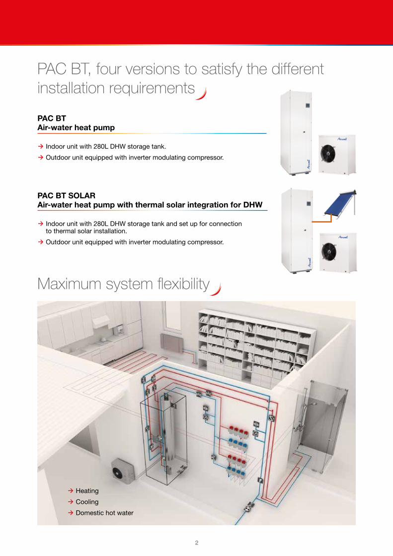
PAC BT, four versions to satisfy the different installation requirements
PAC BT Air-water heat pump
q Indoor unit with 280L DHW storage tank.
q Outdoor unit equipped with inverter modulating compressor.
PAC BT SOLAR Air-water heat pump with thermal solar integration for DHW
q Indoor unit with 280L DHW storage tank and set up for connection to thermal solar installation.
q Outdoor unit equipped with inverter modulating compressor.
Maximum system flexibility
q Heating
q Cooling
q Domestic hot water

32
Just feel well
Comfort and seasonal efficiencySince the maximum power generated by the system is requested only for short periods of time, it is fundamental to dispose of the maximum efficiency in the conditions of part-load.
This is the only way to actually reduce overall yearly consumptions.
Thanks to automatic capacity modulation, the direct current inverter compressor supplies only the thermal energy that is strictly necessary, thereby avoiding useless wasting of energy and increasing the energy efficiency so that the exchange surfaces are larger in relation to the output capacity.
CAPACITY MODULATION
COP 2,5
COP 2,7
COP 3
COP 3,1
COP 3,5
COP 4,9
External air temperature (°C)
External air temperature (°C)
Heat pumpCompressorOn-Off
PAC BTDC inverter Compressor
Thermal load
0
1
2
3
4
5
6
7
0
1
2
3
4
5
6
7
0
50
100
150
200
250
300
350
-5 0 5 10 15 20
-5 0 5 10 15 20
2
0
2
2
8
10
12
14
Hea
ting
cap
acity
[kV
Vt]
CO
P
Hou
rs o
f the
occ
urre
nce
of s
pec
ific
outs
ide
tem
per
atur
e
Inverter modulation zone
SEASONAL EFFICIENCY
• Optimized running at partial load =
Higher COP• Heating capacity =
Heating needs
PAC BT works for most of the time with COP between 3 and 5

4
Indoor unitEASY TO INSTALL
The most important components of the system are fitted in the indoor unit and this makes installation steps easier, as they do not need to be inserted externally.
All elements are controlled and optimized by the control system.
The unit is already designed for domestic water recirculation, which can therefore be installed by reducing additional costs to a minimum and can considerably increase comfort levels.
ADAPTABILITY TO THE INSTALLATION
PAC BT is equipped with a DC circulator which provides significant energy savings over a conventional circulator.
The DC circulator can also be adjusted when first started up to compensate the actual pressure drop of the system, thus further reducing energy consumption.
HIGH SANITARY COMFORT
The storage tank has a volume of 280L that can fulfil high demand for domestic hot water.
The thermal energy produced by the heat pump is quickly and efficiently transferred to the storage tank via the plate exchanger, which also makes maintenance work easier.
If there is a considerable demand for domestic hot water, along with the energy stored in the storage tank, all the available capacity of the heat pump can be provided as well.
WIDE ACCESS AND REDUCTION OF OVERALL DIMENSIONS
PAC BT is carefully designed to optimise the layout of components and to give comfortable access to them from the front. This makes support and maintenance work easier, while reducing overall dimensions to a minimum to protect spaces in the property.
INTEGRATED THERMAL SOLAR INSTALLATION
PAC BT SOLAR has a plate exchanger dedicated to the connection with a thermal solar system and can manage the production of domestic hot water with the best possible energy efficiency by favouring (when available) direct solar energy through thermal solar panels or by using indirect energy in the air through the heat pump.

54
Just feel well
Outdoor unitMAXIMUM SEASONAL EFFICIENCY
This unit can control, at each instant, the delivered capacity according to the demand on the system.
Very high efficiency values can be achieved thanks to the inverter compressor that can constantly modulate capacity
ICE PROTECTION SYSTEM
The ICE PROTECTION SYSTEM device prevents icing on the base of the external exchanger during winter operation, thanks to a special subcooling circuit.
This prevents damages caused by freezing.
ADAPTABILITY TO THE COLD CLIMATES
The unit’s broad operating limits allow PAC BT to fulfil heating demand even in the coldest of climates.
Indeed the unit can ensure the suitable supply temperature to feed a heating system down to an outdoor temperature of –20°C.
Twu [°C] = leaving exchanger water temperature
Ta [°C] = internal exchanger inlet air temperature
SILENCE
The fans in the PAC BT outdoor unit have been carefully designed to achieve the lowest noise levels in all operating modes.
Moreover, the fan varies its speed in relation to conditions by becoming even quieter.
COMPACT AESTHETIC
The position of outdoor units is always a critical aspect of installing systems to ensure comfort.
This is why the PAC BT outdoor unit has been designed to have a simple, compact design and to fulfil aesthetic needs, thereby allowing you to easily access all its internal components and making it easier to conduct maintenance work.
Super quiet
6
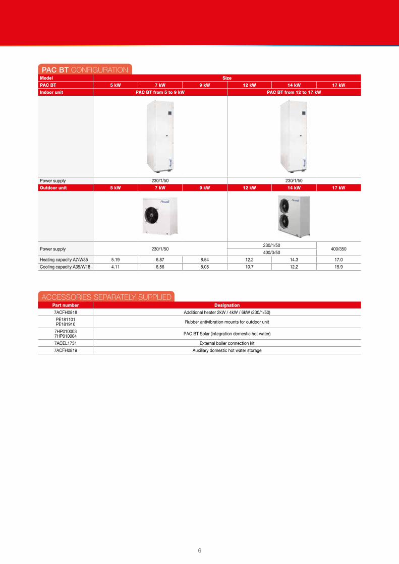
PAC BT CONFIGURATIONModel Size
PAC BT 5 kW 7 kW 9 kW 12 kW 14 kW 17 kW
Indoor unit PAC BT from 5 to 9 kW PAC BT from 12 to 17 kW
Power supply 230/1/50 230/1/50
Outdoor unit 5 kW 7 kW 9 kW 12 kW 14 kW 17 kW
Power supply 230/1/50230/1/50
400/350400/3/50
Heating capacity A7/W35 5.19 6.87 8.54 12.2 14.3 17.0
Cooling capacity A35/W18 4.11 6.56 8.05 10.7 12.2 15.9
ACCESSORIES SEPARATELY SUPPLIEDPart number Designation
7ACFH0818 Additional heater 2kW / 4kW / 6kW (230/1/50)
PE181101 PE181910 Rubber antivibration mounts for outdoor unit
7HP0100037HP010004 PAC BT Solar (integration domestic hot water)
7ACEL1731 External boiler connection kit
7ACFH0819 Auxiliary domestic hot water storage

76
Just feel well
GENERAL TECHNICAL DATASize 5 kW 7 kW 9 kW 12 kW 14 kW 17 kWUSE WITH RADIANT PANELSHeatingHeating capacity 1 kW 5.19 6.87 8.54 12.2 14.3 17.0Total power input 2 kW 1.32 1.76 2.18 3.13 3.67 4.35COP (EN 14511:2013) 3 3.94 3.91 3.91 3.91 3.91 3.91ErP Classe energetica Riscaldamento d’ambiente - Clima MEDIO - W55 (1) 13 A++ A++ A++ A++ A++ A++
ErP Domestic Hot Water Energy Class 14 A A A A A AErP Domestic Hot Water Profile 15 XL XL XL XL XL XLErP System Energy Class - AVERAGE Climate - W55 16 A++ A++ A++ A++ A++ A++
CoolingCooling capacity 6 kW 4.11 6.56 8.05 10.7 12.2 15.9Total power input 2 kW 1.07 1.78 2.23 2.76 3.38 4.38EER (EN 14511:2013) 7 3.85 3.69 3.61 3.86 3.61 3.64ESEER 8 5.3 6.14 4.87 6.59 6.06 5.56Water flow-rate 1 l/s 0.25 0.33 0.41 0.58 0.68 0.81Pump nominal available pressure 1 kPa 51 50 47 53 47 37Max. available pressure kPa 71 63 55 78 70 54USE WITH TERMINAL UNITSHeatingHeating capacity 4 kW 5.01 6.59 8.65 11.6 13.6 16.6Total power input 2 kW 1.59 2.11 2.89 3.78 4.50 5.52COP (EN 14511:2013) 3 3.15 3.12 2.99 3.08 3.02 3.01CoolingCooling capacity 9 kW 4.05 5.37 7.19 8.65 11.1 15.5Total power input 2 kW 1.46 1.93 2.79 3.12 4.50 5.91EER (EN 14511:2013) 7 2.77 2.78 2.58 2.77 2.46 2.62ESEER 10 4.08 4.02 3.89 4.03 4.00 4.06Water flow-rate 4 l/s 0.23 0.32 0.42 0.56 0.65 0.74Pump nominal available pressure 4 kPa 51 50 46 55 49 72Max. available pressure kPa 72 65 53 82 73 62USE WITH RADIATORSHeatingHeating capacity 5 kW 4.72 6.30 8.00 10.6 12.5 15.3Total power input 2 kW 1.96 2.59 3.54 4.65 5.74 6.95COP (EN 14511:2013) 3 2.41 2.44 2.26 2.29 2.17 2.20Water flow-rate 5 l/s 0.11 0.15 0.19 0.25 0.30 0.37Pump nominal available pressure 5 kPa 46 48 50 65 64 62Max. available pressure kPa 75 75 73 102 100 96Water circuitMin. installation water contents l 17 20 25 33 40 50Solar exchanger capacity (only for PAC BT Solar version) W/K 2703 2703 2703 3186 3186 3186
DHW storage capacity l 280 280 280 280 280 280CompressorType of compressors ROTARY INVERTER DC ROTARY INVERTER DCRefrigerant R-410A R-410A R-410A R-410A R-410A R-410AOil charge 0.35 0.35 0.87 1.70 1.70 1.90User side exchangerType of internal exchanger 11 PHE PHE PHE PHE PHE PHEWater content l 0.64 0.64 0.64 1.8 1.8 1.8External Section FansType of fans 12 AX AX AX AX AX AXno. of fans No 1 1 1 1 1 1Standard airflow l/s 653 1028 1028 2056 1996 2222Power supplyStandard power supply 230/1/50 230/1/50 230/1/50 400/3/50+N 400/3/50+N 400/3/50+N
The Product is compliant with the ErP (Energy Related Products) European Directive. It includes the Commission delegated Regulation (EU) No 811/2013 (rated heat output ≤ 70 kW at specified reference conditions) and the Commission delegated Regulation (EU) No 813/2013 (rated heat output ≤ 400 kW at specified reference conditions)
1. Entering/leaving water temperature user side 30/35°C, Entering external exchanger air temperature 7 °C (R.H. = 85%).
2. The overall power absorbed is calculated by adding the power absorbed by the compressor + the power absorbed by the fans + the power absorbed by the auxiliary electrical circuit + the percentage value of the pump to overcome pressure drops inside the unit.
3. COP (EN 14511:2013) performance coefficient in heating mode. Ratio between heating capacity supplied and absorbed power in accordance with EN 14511:2013. The absorbed power is the sum of the power absorbed by the compressor + power absorbed by the fans + the power absorbed by the electric auxiliary circuit + the percentage value of the pump to overcome pressure drops inside the unit.
4. Entering/leaving water temperature user side 40/45°C, Entering external exchanger air temperature 7 °C (R.H. = 85%).
5. Entering/leaving water temperature user side 45/55°C, Entering external exchanger air temperature 7°C (R.H. = 85%).
6. Entering/leaving water temperature user side 23/18°C, Entering external exchanger air temperature 35°C.
7. EER (EN 14511:2013) performance coefficient in cooling mode. Ratio between cooling capacity provided and power absorbed in compliance with EN 14511:2013. The absorbed power is the sum of the power absorbed by the compressor + power absorbed by the fans + the power absorbed by the electric auxiliary circuit + the percentage value of the pump to overcome
pressure drops inside the unit.8. ESEER calculated by Airwell for radiant systems with water produced at 18°C by taking into
account the load conditions and source water temperature as defined by EUROVENT for water at 7°C.
9. User side entering/leaving water temperature 12/7 °C, external exchanger entering air 35°C.10. ESEER calculated by EUROVENT, for systems featuring terminal units with water produced at 7°C.11. PHE = plate exchanger.12. AX = axial fan.13. Seasonal Space Heating Energy Efficiency Class according to Commission delegated
Regulation (EU) No 811/2013. W = Water outlet temperature (°C).14. Water Heating Energy Efficiency Class according to Commission delegated Regulation (EU)
No 811/2013.15. Considered Load profile for the definition of Domestic Hot Water Energy Class according to
Commission delegated Regulation (EU) No 811/2013 Class of the package with RCW15 thermostat.
16. Seasonal Space Heating Energy Efficiency Class of the package according to Commission delegated Regulation (EU) No 811/2013.

8
ELECTRICAL DATA
■■ Outdoor unit
SUPPLY VOLTAGE 230/1/50
Size 5 kW 7 kW 9 kW 12 kW 14 kW
F.L.A. - FULL LOAD CURRENT AT MAX ADMISSIBLE CONDITIONS
F.L.A. - External fan unit A 0.51 0.60 0.60 0.60 0.60
F.L.A. - Total A 11.41 14.55 18.03 23.96 28.24
F.L.I. - FULL LOAD POWER INPUT AT MAX ADMISSIBLE CONDITIONS
F.L.I. - External fan unit kW 0.12 0.15 0.15 0.15 0.15
F.L.I. - Total kW 2.69 3.42 4.22 5.68 6.63
M.I.C. - MAXIMUM INRUSH CURRENT
M.I.C. - Value A 11.99 15.13 18.61 25.26 29.54
Power supply 230/1/50 Hz +/-10%For non standard voltage please contact Airwell technical officeThe units are compliant with the provisions of European standards CEI EN 60204 and CEI EN 60335.
SUPPLY VOLTAGE 400/3/50+N
Size 12 kW 14 kW 17 kW
F.L.A. - FULL LOAD CURRENT AT MAX ADMISSIBLE CONDITIONS
F.L.A. - External fan unit A 0.60 0.60 2.10
F.L.A. - Total A 13.30 13.70 23.90
F.L.I. - FULL LOAD POWER INPUT AT MAX ADMISSIBLE CONDITIONS
F.L.I. - External fan unit kW 0.15 0.15 0.48
F.L.I. - Total kW 3.80 4.50 7.10
Power supply 400/3/50 (+ NEUTRAL) +/- 10%Maximum Phase Unbalance: 2%For non standard voltage please contact Airwell technical officeThe units are compliant with the provisions of European standards CEI EN 60204 and CEI EN 60335.
■■ Indoor unit
Voltage 230/1/50 ± 10%
Size PAC BT from 5 to 9 kW PAC BT from 12 to 17 kW
F.L.A. - FULL LOAD CURRENT AT MAX ADMISSIBLE CONDITIONS
F.L.A. - Pump A 0.90 1.40
F.L.A. - Heating elements 1 A 8.70 8.70
F.L.A - Total A 9.60 10.10
F.L.I. - FULL LOAD POWER INPUT AT MAX ADMISSIBLE CONDITIONS
F.L.I. - Pump kW 0.21 0.30
F.L.I. - Heating elements 1 kW 2.00 2.00
F.L.I. - Total 1 kW 2.21 2.30
Power supply 230/1/50 Hz +/-10%The pump is included in the total values calculation for non standard voltage please contact Airwell technical officeThe units are compliant with the provisions of European standards CEI EN 60204 and CEI EN 60335.1. The electric heater inserted in the domestic hot water tank is never activated at
the same time as the compressor in order to prevent high electrical power levels, which would result in a greater contactor.
2. If there is the 7ACFH0818 accessory 5-7-9 kW Integrated electric heater, electrical data must be increased. The power draw of the heater must be considered when rating the power line.
Caution: when defining the size, make sure all absorption values are compliant with current power supply contracts in the country of installation.
SOUND LEVELS
Size
Sound power level Sound pressure
level
Sound power levelOctave band (Hz)
63 125 250 500 1000 2000 4000 8000 dB(A) dB(A)
2.1 73 73 70 65 63 59 51 36 49 64
3.1 76 70 65 60 58 53 46 48 49 64
4.1 76 71 66 61 59 54 47 49 49 64
5.1 76 71 69 66 63 58 50 39 53 68
7.1 77 71 69 67 63 59 50 40 54 69
8.1 83 77 69 61 63 67 60 61 56 72
Sound levels refer to units with full load under nominal test conditions.The sound pressure level refers to a distance of 1 meter from the outer surface of the unit operating in open field.Noise levels are determined using the tensiometric method (UNI EN ISO 9614-2).Data referred to the following conditions: Entering / leaving exchanger water temperature user side 12/7°C.
Entering / leaving exchanger water temperature source side 30/35°C.

98
Just feel well
ADMISSIBLE WATER FLOW RATES
q Min. (Qmin) and max. (Qmax) water flow-rates admissibles for the correct unit operation.
Size 5 kW 7 kW 9 kW 12 kW 14 kW 17 kW
Minimum flow l/s 0.15 0.18 0.18 0.23 0.34 0.32
Maximum flow-rate l/s 0.90 0.90 0.90 1.10 1.50 1.70
FOULING CORRECTION FACTORS
Internal exchanger
m²C/W F1 FK1
0.44 x 10 (-4) 1.00 1.00
0.44 x 10 (-4) 0.97 0.99
0.44 x 10 (-4) 0.94 0.88
The cooling performance values provided in the tables are based on the external exchanger having clean plates (fouling factor 1). For different fouling factor values, multiply the performance by the coefficients shown in the table.F1 = Cooling capacity correction factors.FK1 = Compressor power input correction factor.
PRESSURE CURVES OF THE INSTALLATION CIRCULATOR
■■ PAC BT 5-7-9 kW ■■ PAC BT 12-14-17 kW
DP [kPa] = Available pressureQ [l/s] = water flow-ratethe heads are intended as available at the unit connections
SYSTEM CIRCULATOR ABSORPTION CURVES
■■ PAC BT 5-7-9 kW ■■ PAC BT 12-14-17 kW
Pe [W] = Electric power consumptionQ [l/s] = water flow-rate

10
OPERATING RANGE
■■ COOLINGPAC BT 5 TO 9 KW PAC BT 12 TO 17 KW
Twu [°C] = outlet exchanger water temperature. Tae [°C]: External exchanger inlet air temperature.1. Normal operating range2. Normal operating range, with modulating fans3. Operating range where the use of ethylene glycol is mandatory in relation to the temperature of the water at the outlet of the user side exchanger4. Operating range with modulating compressor
■■ HEATINGPAC BT 5 TO 9 KW PAC BT 12 TO 17 KW
Twu [°C] = outlet exchanger water temperature. Tae [°C]= External exchanger inlet air temperature.1. Normal operating range2. Operating range with modulating compressor3. Operation with fans and compressors in modulation4. Operating range with the use of the resistance (optional)
■■ DOMESTIC HOT WATERPAC BT 5 TO 9 KW PAC BT 12 TO 17 KW
Twu [°C] = outlet exchanger water temperature. Tae [°C]= External exchanger inlet air temperature1. Normal operating range2. Operating range with modulating compressor3. Operation with fans and compressors in modulation4. Operating range with the use of the resistance (optional)

1110
Just feel well
Indoor unit: composition and features
■■ StructureSupporting structure made with zinc-magnesium sheet metal that ensures excellent mechanical features and high long-term resistance against corrosion.
■■ PanellingOuter panelling made of painted zinc-magnesium sheet metal RAL 9001. Each panel can be easily removed to give full access to internal components.
■■ Internal exchangerDirect expansion heat exchanger, braze-welded AISI 316 stainless steel plates with large exchange surface and complete with external heat and anti-condensate insulation.
■■ Domestic hot water circuit1 280L domestic hot water storage tank with glassified inside and external
polyurethane coating (40mm thickness) with PVC finishing2 Electronic anode3 2 kW safety and anti-legionella cycle heating element4 Exchanger with stainless steel braze-welded plates (AISI 316) for the
domestic hot water production5 Exchanger with stainless steel braze-welded plates (AISI 316) for the
domestic hot water production by a thermal solar installation (onlt for PAC BT Solar version)
6 DHW recirculation circulator7 Domestic hot water system recirculation circulator8 Automatic air blow valve, left water side9 Domestic hot water side safety valve 6bar
10 Storage drain bibcock11 Probe sump for solar thermal system control12 Domestic water expansion vessel connection13 Limestone cleaning bibcock
■■ Water circuit14 Direct-current primary circulator15 Differential pressure switch, water side16 System drain bibcock17 Water side safety valve 3bar18 Switching 3-way valve of the DHW or installation water19 System expansion vessel connection
■■ Refrigeration circuit20 Electronic expansion valve
■ 21 Electrical panelThe capacity section includes:• Anti-legionellosis heater control contactor• Main isolator switch• Heaters fuses• Auxiliary circuit fuse• Primary circulator fuses
22 Control SOFT-TOUCH keypad including:• Displaying the operating status (setpoint / outside temperature / supply temperature / alarms, etc.)• Summer/winter season changeover• Forcing for recharging the domestic water storage• Hourly domestic water recharge scheduling (+ manual forcing)• Anti-legionella function scheduling• Summer/winter climate setting• Hhourly/weekly domestic water recirculation scheduling
22 Supplementary electric heaters of 2kW / 4kW / 6kW ( Separately supplied option)23 Components performed by Customer

12
Outdoor unit: composition and features
■ 1 CompressorSize 5-7-9 kWInverter controlled rotary-type hermetic compressor equipped with a motor protection device for overheating, overcurrents and excessive temperatures of the supply gas. It is installed on anti-vibration mounts and it is equipped with oil charge.An oil heater, which starts automatically, keeps the oil from being diluted by the refrigerant when the compressor stops.Size 12-14-17 kWInverter controlled scroll-type hermetic compressor equipped with a motor protection device for overheating, overcurrents and excessive temperatures of the supply gas. It is installed on anti-vibration mounts and is equipped with oil charge.An oil heater, which starts automatically, keeps the oil from being diluted by the refrigerant when the compressor stops.
■ 2 StructureStructure made entirely in Zinc–Magnesium plate that guarantees excellent mechanical characteristics and high corrosion strength over time.Zinc-magnesium base painted with polyester powder RAL 9001
■ 3 PanellingExternal RAL 9001 painted zinc-magnesium sheet metal panelling that ensures superior resistance to corrosion for outdoor installation and eliminates the need for periodic painting. Each panel can be easily removed to allow full access to internal components.
■ 4 External exchangerDirect expansion finned exchanger, made from copper pipes in staggered rows and mechanically expanded to the fin collars. The fins are made from aluminium with a corrugated surface and adequately distanced to ensure the maximum heat exchange efficiency. A correct power supply to the expansion valve is ensured by the subcooling circuit; this circuit also prevents the formation of ice at the base of the heat exchanger during winter operation.The unit is fitted as standard with coil protection grills.
■ 5 FanAxial fans with shaped die-cast aluminium blades coupled directly onto the single-phase electric motor with external rotor in compliance with VDE 0530/12.84, with built-in thermal protection, IP 54 rating in accordance with DIN 40 050.Placed into aerodynamic shaped nozzles, to increase efficiency and minimize the noise level, are equipped of protection grilles to avoid accidents.
■■ Refrigeration circuit6 Refrigeration circuit with:7 Electronic expansion valve
4 Way reverse cycle valve8 Filter dryer
9 Liquid receiver10 Inlet liquid separator
• Pressure probes• Low pressure safety• High pressure safety
Liquid and gas shut-off valves with service fitting
■■ Drain panThermoformed ABS condensate collection tray fitted with drain pipe.
■ 11 Electrical panelThe control section includes:• Relay for remote cumulative fault signal• Dynamic control system for optimisation of the defrost cycles• Condenser control• RS485 serial• Probe of the outdoor air temperature.
Client connection with 2 digital inputs, configurable as:• Remote ON-OFF• Remote mode change (hot/cold)• Remote system call• Second remote system set point

1312
Just feel well
Definition of the cooling and heating capacity leakThe length of the refrigerant lines involves a worsening of the heating and cooling capacity supplied to the system and to the domestic hot water.
In the graph is possible to determine the value of this efficiency reduction
PAC BT connections with outdoor unitREFRIGERATING LINE CONNECTIONS
q Maximum equivalent length of the lrefrigerant lines 25mq Maximum level difference 15m
Size 5 kW 7 kW 9 kW 12 kW 14 kW 17 kW
External diameter gas line 3/8” (9.52 thickness 0.8 mm) 1/2” (12.7 thickness 0.8mm) 5/8” (15.88 thickness 1mm) 3/4” (19.05 thickness
1mm)
External diameter liquid line 3/8” (9.52 thickness 0.8mm) 1/2” (12.7 thickness 0.8mm)
Equivalent length of the lines (metres ) = Effective length (metres) + (Q.ty of curves x K)Consider K = 0.3 for wide-range elbow bendsConsider K=0.5 m for standard 90° elbow curves.
CAUTION: for the correct realisation of the refrigerant lines, refrigerant gas, refer to the PAC BT MANUAL.
REFRIGERANT CHARGE
The outdoor unit is preloaded with refrigerant gas, while the indoor unit is supplied loaded with nitrogen. The preload is enough to cover a distance of up to 5 m between the two units.
Refrigerant charge (R-410A)
Size 5 kW 7 kW 9 kW 12 kW 14 kW 17 kW
R410a kg 2.9 2.9 2.9 4.9 6.6 8.5
ELECTRICAL CONNECTIONS
The internal and external PAC BT units must be individually powered.Along with the power supply, it is necessary to connect a communication cable between the outdoor and indoor unit.
Directions for the electric connection between the indoor unit and the exteral unit:q Maximum length of the connection cable: 30 metersq Cat.5 Ethernet cableq Separate installation in relation to the capacity conductors
C = Performance curve of the cooling capacityH = Performance curve of the heating capacity

14
Water connection diagramsInstallation is the responsibility of the Client, externally to the unit.
A System valve PS solar pump
I.A. Aqueduct inlet RID Pressure reducing valve
C.C. Components performed by Customer VEACS Domestic hot water expansion tank
DEF Dirt separator VEI System expansion tank
F Water filter VES Solar expansion tank
M Pressure gauge VR check valve
P.A. Descaler protection VT Mixing valve thermostatic
1 Domestic hot water outlet
2 Aqueduct inlet
3 Return from user side system
4 User side system supply
5 Gas line
6 Liquid line
8 Return from solar system
9 Supply to solar system
10 Dhw recirculation circuit inlet
Antivibration joints
Cut-off valves
vent
PAC BT UE

1514
Just feel well
Dimension criteria in heatingThe first stage in selecting the heat pump is based on project heat load requirements, in other words, the maximum temperature lost in the premises during winter project conditions (in alignment with winter project temperatures for examined sites, excluding heat sources).
Design procedure foresees the selection of a heat generator capable of generating, under design conditions, power equal to, or greater than, that lost by the building under the same conditions.
In the case of the PAC BT and PAC BT Solar version, if the design thermal load is greater than the heating capacity supplied by the unit under the same conditions, you can still install the unit, provided there are integration systems with an electric heater.
ELECTRIC HEATER
PAC BT has an optional electric heater that can supply a heating capacity of up to 4 kW and 6 kW. This electric heater is integrated into the unit and can modulate its capacity output to minimise power consumption.
As there is no justified reason in terms of energy to choose the size of the heat pump based on the minimum outdoor air temperature, given that there are very few hours of operation, it is preferable to use an electric heater.
The graph below shows the case of a building with a thermal load under design conditions equal to 9 kW, with an outdoor air temperature of -5°C. Since the heat pump, with water supply at 35°C, can deliver 6.8 kW under the same outdoor air conditions (-5°C), the difference in capacity (9 – 6.8 = 2.2 kW) is provided by the electric heater. The electric resistor operates until the building’s heating capacity demand equals the maximum capacity supplied (at 100%) by the unit which, in this case, happens at a outdoor temperature of 0°C.
Due to the limited number of hours involving low fresh air temperatures for the premises involved, the power required to the integrated heater is relatively low compared to the power required from the heat pump. As such, seasonal efficiency performance is not compromised. In the example of the load described above, the overall electric energy absorbed by the heat pump + the electric heater is equivalent to 6266 kWh and the value of the only electric resistance is lower than 1%.
Thanks to the control of the indoor temperature in the various areas, during actual operation the capacity demand will be lower and, as a result, the electric heater will be used less as well.
In the above example of load, the overall electrical power absorption of the heat pump + the electric heater is 3966 kWhe, so that the contribution of the electric heater is 3%.
Qt = heating energy requested by the buildingTae = outdoor air temperature1. Produced heat energy2. Heating energy produced by the electric heaters
Pt= delivered heat capacityTw = supply water temperatureTae = outdoor air temperature
16
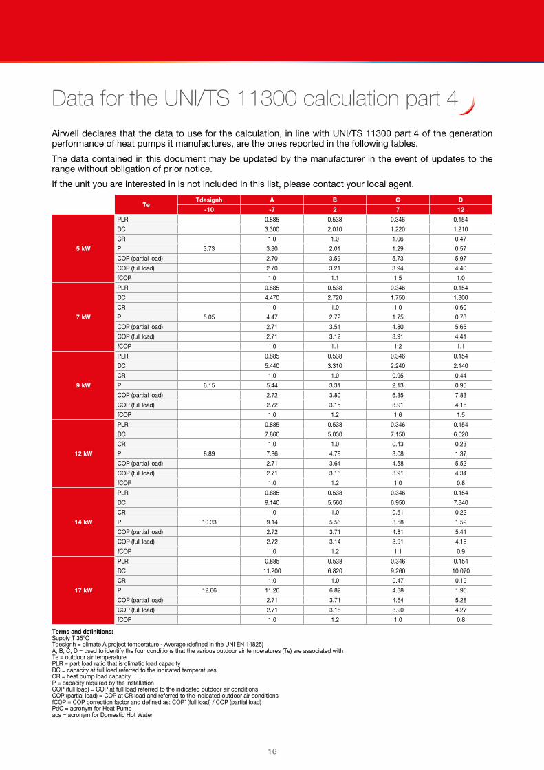
Data for the UNI/TS 11300 calculation part 4Airwell declares that the data to use for the calculation, in line with UNI/TS 11300 part 4 of the generation performance of heat pumps it manufactures, are the ones reported in the following tables.
The data contained in this document may be updated by the manufacturer in the event of updates to the range without obligation of prior notice.
If the unit you are interested in is not included in this list, please contact your local agent.
TeTdesignh A B C D
-10 -7 2 7 12
5 kW
PLR 0.885 0.538 0.346 0.154
DC 3.300 2.010 1.220 1.210
CR 1.0 1.0 1.06 0.47
P 3.73 3.30 2.01 1.29 0.57
COP (partial load) 2.70 3.59 5.73 5.97
COP (full load) 2.70 3.21 3.94 4.40
fCOP 1.0 1.1 1.5 1.0
7 kW
PLR 0.885 0.538 0.346 0.154
DC 4.470 2.720 1.750 1.300
CR 1.0 1.0 1.0 0.60
P 5.05 4.47 2.72 1.75 0.78
COP (partial load) 2.71 3.51 4.80 5.65
COP (full load) 2.71 3.12 3.91 4.41
fCOP 1.0 1.1 1.2 1.1
9 kW
PLR 0.885 0.538 0.346 0.154
DC 5.440 3.310 2.240 2.140
CR 1.0 1.0 0.95 0.44
P 6.15 5.44 3.31 2.13 0.95
COP (partial load) 2.72 3.80 6.35 7.83
COP (full load) 2.72 3.15 3.91 4.16
fCOP 1.0 1.2 1.6 1.5
12 kW
PLR 0.885 0.538 0.346 0.154
DC 7.860 5.030 7.150 6.020
CR 1.0 1.0 0.43 0.23
P 8.89 7.86 4.78 3.08 1.37
COP (partial load) 2.71 3.64 4.58 5.52
COP (full load) 2.71 3.16 3.91 4.34
fCOP 1.0 1.2 1.0 0.8
14 kW
PLR 0.885 0.538 0.346 0.154
DC 9.140 5.560 6.950 7.340
CR 1.0 1.0 0.51 0.22
P 10.33 9.14 5.56 3.58 1.59
COP (partial load) 2.72 3.71 4.81 5.41
COP (full load) 2.72 3.14 3.91 4.16
fCOP 1.0 1.2 1.1 0.9
17 kW
PLR 0.885 0.538 0.346 0.154
DC 11.200 6.820 9.260 10.070
CR 1.0 1.0 0.47 0.19
P 12.66 11.20 6.82 4.38 1.95
COP (partial load) 2.71 3.71 4.64 5.28
COP (full load) 2.71 3.18 3.90 4.27
fCOP 1.0 1.2 1.0 0.8
Terms and definitions:Supply T 35°CTdesignh = climate A project temperature - Average (defined in the UNI EN 14825)A, B, C, D = used to identify the four conditions that the various outdoor air temperatures (Te) are associated withTe = outdoor air temperaturePLR = part load ratio that is climatic load capacityDC = capacity at full load referred to the indicated temperaturesCR = heat pump load capacityP = capacity required by the installationCOP (full load) = COP at full load referred to the indicated outdoor air conditionsCOP (partial load) = COP at CR load and referred to the indicated outdoor air conditionsfCOP = COP correction factor and defined as: COP’ (full load) / COP (partial load)PdC = acronym for Heat Pumpacs = acronym for Domestic Hot Water

1716
Just feel well
PerformanceSIZE 5 KW - HEATING
To Tae (°C)DB/WB Heating capacity COP
°C °C 100% 90% 70% 50% 40% 100% 90% 70% 50% 40%
25
-20/-20.1 - - 1.16 0.70 0.48 - - 1.74 1.82 1.90
-10/-10.5 2.96 2.70 2.03 1.28 0.91 2.92 2.94 3.00 3.05 3.05
-7/-8 3.50 3.19 2.44 1.62 1.21 3.44 3.48 3.56 3.64 3.66
0/-0.6 4.01 3.61 2.88 2.16 1.81 3.87 3.93 4.07 4.23 4.32
2/1.1 4.26 3.88 3.02 2.12 1.67 4.07 4.13 4.29 4.47 4.57
7/6 5.35 4.81 3.75 2.69 2.16 5.08 5.18 5.42 5.69 5.83
12/10.2 6.06 5.50 4.28 3.02 2.39 5.81 5.94 6.25 6.59 6.77
15/13 6.49 5.89 4.57 3.20 2.52 6.28 6.44 6.79 7.17 7.36
20/16 7.21 6.55 5.07 3.51 2.73 7.08 7.27 7.72 8.20 8.44
35
-20/-20.1 - - 0.98 0.59 0.39 - - 1.31 1.39 1.48
-10/-10.5 2.78 2.52 2.17 1.17 0.82 2.30 2.32 2.36 2.46 2.51
-7/-8 3.30 3.01 2.61 1.50 1.10 2.70 2.76 2.80 2.94 3.01
0/-0.6 3.90 3.49 3.04 2.04 1.69 3.06 3.12 3.19 3.41 3.52
2/1.1 4.14 3.74 3.25 2.00 1.56 3.20 3.26 3.34 3.60 3.74
7/6 5.19 4.66 4.05 2.56 2.03 3.94 4.02 4.14 4.50 4.68
12/10.2 5.83 5.24 5.16 2.82 2.21 4.40 4.50 4.62 5.10 5.33
15/13 6.3 5.7 4.9 3.0 2.4 4.75 4.88 5.04 5.56 5.82
20/16 7.2 6.4 4.6 3.4 2.6 5.34 5.50 6.08 6.36 6.69
45
-20/-20.1 - - - 0.58 0.37 - - - 1.28 1.36
-10/-10.5 2.65 2.36 1.72 1.04 0.71 1.85 1.87 1.92 1.98 2.03
-7/-8 3.0 2.65 1.96 1.25 0.90 2.04 2.06 2.13 2.21 2.27
0/-0.6 3.7 3.23 2.49 1.80 1.46 2.40 2.45 2.55 2.68 2.77
2/1.1 3.9 3.5 2.63 1.78 1.35 2.54 2.59 2.71 2.87 2.99
7/6 5.0 4.5 3.4 2.4 1.83 3.15 3.22 3.38 3.59 3.73
12/10.2 5.61 4.96 3.73 2.54 1.94 3.48 3.56 3.76 4.04 4.23
15/13 6.0 5.4 4.0 2.7 2.1 3.71 3.80 4.04 4.34 4.57
20/16 6.8 6.0 4.5 3.0 2.3 4.08 4.20 4.48 4.87 5.15
55
-20/-20.1 - - - - - - - - - -
-10/-10.5 - - - - - - - - - -
-7/-8 2.84 2.54 1.88 1.17 0.82 1.63 1.64 1.69 1.75 1.80
0/-0.6 3.48 3.08 2.36 1.68 1.34 1.86 1.89 1.97 2.07 2.13
2/1.1 3.72 3.32 2.49 1.65 1.23 1.96 2.00 2.08 2.20 2.29
7/6 4.72 4.20 3.17 2.15 1.64 2.41 2.45 2.57 2.73 2.84
12/10.2 5.31 4.72 3.54 2.36 1.78 2.64 2.69 2.84 3.04 3.18
15/13 5.8 5.1 3.8 2.5 1.89 2.80 2.87 3.03 3.26 3.42
20/16 6.5 5.8 4.3 2.8 2.1 3.07 3.15 3.35 3.62 3.84
60
-20/-20.1 - - - - - - - - - -
-10/-10.5 - - - - - - - - - -
-7/-8 - - - - - - - - - -
0/-0.6 3.3 2.9 2.22 1.57 1.24 1.42 1.44 1.50 1.58 1.64
2/1.1 3.6 3.2 2.39 1.56 1.15 1.50 1.53 1.59 1.69 1.77
7/6 4.6 4.1 3.1 2.08 1.57 1.86 1.89 1.99 2.12 2.22
12/10.2 4.98 4.44 3.32 2.19 1.63 1.94 1.98 2.09 2.24 2.36
15/13 5.3 4.7 3.5 2.3 1.69 2.01 2.06 2.17 2.34 2.47
20/16 5.8 5.1 3.8 2.5 1.8 2.12 2.17 2.31 2.50 2.66
To = Leaving internal exchanger water temperature (°C)Eat [°C]: external exchanger inlet air temperaturePerformances in function of the inlet/outlet water temperature differential = 5°CHeating capacity and COP calculated according to EN 14511:2013ATTENTION: The data of the heat capacity and COP include defrostings.DB = dry bulbWB = wet bulb

18
SIZE 5 KW - COOLING
To Tae Cooling capacity EER
°C °C 100% 90% 75% 60% 50% 40% 100% 90% 75% 60% 50% 40%
5
20 4.62 4.13 3.57 2.75 2.27 1.78 4.12 4.18 4.29 4.42 4.54 4.70
25 4.36 3.91 3.38 2.62 2.17 1.71 3.52 3.57 3.67 3.78 3.89 4.03
30 4.11 3.69 3.20 2.49 2.07 1.64 3.02 3.07 3.16 3.26 3.35 3.46
35 3.85 3.46 3.01 2.35 1.96 1.57 2.71 2.76 2.84 2.92 3.00 3.09
40 3.60 3.24 2.82 2.22 1.86 1.50 2.17 2.21 2.29 2.36 2.43 2.50
45 - 3.02 2.63 2.08 1.76 1.42 - 1.80 1.88 1.94 1.99 2.06
7
20 4.86 4.35 3.76 2.90 2.39 1.88 4.33 4.41 4.56 4.73 4.88 5.07
25 4.59 4.12 3.56 2.77 2.29 1.81 3.68 3.75 3.89 4.03 4.16 4.32
30 4.32 3.88 3.37 2.63 2.19 1.75 3.15 3.21 3.33 3.45 3.56 3.70
35 4.05 3.65 3.18 2.50 2.09 1.68 2.77 2.83 2.94 3.04 3.12 3.23
40 3.78 3.41 2.98 2.36 1.99 1.61 2.27 2.32 2.42 2.50 2.57 2.66
45 - 3.18 2.79 2.22 1.89 1.55 - 1.92 2.01 2.08 2.14 2.21
12
20 5.47 4.90 4.23 3.28 2.70 2.12 4.84 4.99 5.24 5.49 5.71 6.00
25 5.16 4.64 4.02 3.13 2.60 2.07 4.08 4.21 4.43 4.63 4.82 5.06
30 4.86 4.37 3.80 2.99 2.50 2.01 3.47 3.58 3.77 3.93 4.09 4.28
35 4.56 4.12 3.60 2.86 2.41 1.96 2.93 3.02 3.18 3.32 3.44 3.59
40 4.25 3.85 3.39 2.71 2.31 1.91 2.50 2.58 2.72 2.83 2.93 3.04
45 - 3.59 3.17 2.57 2.21 1.85 - 2.21 2.34 2.42 2.50 2.58
15
20 5.83 5.22 4.51 3.50 2.88 2.27 5.22 5.41 5.73 6.02 6.29 6.62
25 5.50 4.94 4.29 3.35 2.78 2.22 4.29 4.44 4.71 4.95 5.18 5.46
30 5.17 4.66 4.06 3.20 2.68 2.17 3.58 3.71 3.93 4.12 4.31 4.53
35 4.86 4.39 3.85 3.06 2.60 2.12 3.02 3.13 3.32 3.47 3.62 3.79
40 4.53 4.11 3.62 2.92 2.50 2.08 2.56 2.65 2.82 2.94 3.05 3.18
45 - - 3.40 2.78 2.41 2.03 - - 2.41 2.50 2.59 2.69
18
20 6.19 5.55 4.79 3.72 3.07 2.42 5.28 5.49 5.87 6.21 6.53 6.94
25 5.85 5.26 4.57 3.57 2.97 2.37 4.39 4.56 4.87 5.15 5.42 5.76
30 5.51 4.97 4.34 3.43 2.88 2.33 3.69 3.84 4.10 4.32 4.54 4.80
35 5.18 4.68 4.11 3.29 2.79 2.30 3.48 3.61 3.85 4.02 4.19 4.38
40 4.83 4.39 3.88 3.15 2.70 2.26 2.65 2.76 2.95 3.08 3.21 3.36
45 - - 3.65 3.01 2.62 2.23 - - 2.52 2.63 2.73 2.84
To = Leaving internal exchanger water temperature (°C)Eat [°C]: external exchanger inlet air temperaturePerformances in function of the inlet/outlet water temperature differential = 5°CCooling capacity and EER calculated according to EN 14511:2013

1918
Just feel well
SIZE 7 KW - HEATING
To Tae (°C)DB/WB Heating capacity COP
°C °C 100% 90% 70% 50% 40% 100% 90% 70% 50% 40%
25
-20/-20.1 - - 1.61 1.04 0.74 - - 1.83 1.86 1.86
-10/-10.5 3.87 3.53 2.84 1.88 1.38 2.99 3.02 3.07 3.11 3.10
-7/-8 4.58 4.17 3.35 2.29 1.74 3.41 3.45 3.53 3.60 3.62
0/-0.6 5.15 4.64 3.63 2.69 2.23 3.55 3.61 3.74 3.89 3.97
2/1.1 5.53 5.02 4.01 2.84 2.25 3.69 3.76 3.90 4.08 4.17
7/6 6.93 6.23 4.85 3.47 2.78 4.67 4.78 5.01 5.26 5.39
12/10.2 7.88 7.13 5.63 4.00 3.18 5.34 5.47 5.76 6.10 6.27
15/13 8.64 7.81 6.19 4.37 3.45 5.81 5.99 6.36 6.77 6.97
20/16 9.90 8.96 7.11 4.99 3.90 6.57 6.87 7.38 7.94 8.20
35
-20/-20.1 - - 1.49 0.95 0.67 - - 1.23 1.29 1.35
-10/-10.5 3.74 3.38 2.68 1.76 1.28 2.29 2.32 2.37 2.45 2.49
-7/-8 4.47 4.05 3.20 2.16 1.63 2.71 2.74 2.82 2.92 2.97
0/-0.6 5.05 4.52 3.47 2.55 2.10 3.04 3.09 3.21 3.36 3.44
2/1.1 5.40 4.87 3.82 2.68 2.10 3.12 3.19 3.32 3.48 3.58
7/6 6.87 6.17 4.77 3.38 2.69 3.91 4.01 4.21 4.45 4.58
12/10.2 7.83 7.04 5.47 3.84 3.03 4.41 4.52 4.78 5.09 5.27
15/13 8.58 7.72 6.00 4.19 3.28 4.74 4.90 5.21 5.58 5.79
20/16 9.83 8.84 6.89 4.78 3.71 5.27 5.50 5.91 6.40 6.68
45
-20/-20.1 - - - 0.86 0.59 - - - 1.25 1.27
-10/-10.5 3.50 3.12 2.38 1.52 1.08 1.87 1.89 1.93 1.97 1.98
-7/-8 3.9 3.51 2.67 1.76 1.30 2.06 2.08 2.13 2.19 2.22
0/-0.6 4.8 4.29 3.17 2.26 1.83 2.41 2.45 2.55 2.66 2.72
2/1.1 5.2 4.6 3.49 2.38 1.83 2.54 2.59 2.70 2.83 2.90
7/6 6.6 5.9 4.5 3.1 2.44 3.12 3.20 3.35 3.53 3.64
12/10.2 7.47 6.63 4.96 3.40 2.62 3.46 3.55 3.74 3.98 4.12
15/13 8.1 7.2 5.4 3.7 2.8 3.68 3.79 4.02 4.30 4.46
20/16 9.2 8.2 6.1 4.1 3.2 4.04 4.18 4.47 4.82 5.03
55
-20/-20.1 - - - - - - - - - -
-10/-10.5 - - - - - - - - - -
-7/-8 3.76 3.37 2.59 1.69 1.23 1.65 1.67 1.71 1.76 1.78
0/-0.6 4.6 4.1 3.04 2.15 1.71 1.88 1.92 1.98 2.07 2.12
2/1.1 4.9 4.4 3.36 2.27 1.72 1.99 2.02 2.10 2.20 2.26
7/6 6.3 5.6 4.3 2.92 2.25 2.44 2.49 2.60 2.74 2.83
12/10.2 7.09 6.32 4.77 3.23 2.46 2.66 2.73 2.87 3.04 3.15
15/13 7.7 6.9 5.2 3.5 2.65 2.82 2.90 3.07 3.27 3.40
20/16 8.7 7.8 5.9 4.0 3.0 3.08 3.18 3.38 3.64 3.80
60
-20/-20.1 - - - - - - - - - -
-10/-10.5 - - - - - - - - - -
-7/-8 - - - - - - - - - -
0/-0.6 4.6 4.1 3.05 2.14 1.69 1.72 1.75 1.81 1.88 1.93
2/1.1 4.9 4.4 3.35 2.25 1.69 1.81 1.84 1.91 2.00 2.04
7/6 6.2 5.5 4.2 2.83 2.16 2.20 2.25 2.35 2.47 2.54
12/10.2 6.97 6.22 4.72 3.18 2.40 2.40 2.46 2.58 2.73 2.82
15/13 7.5 6.7 5.1 3.4 2.57 2.53 2.60 2.74 2.91 3.01
20/16 8.4 7.5 5.8 3.8 2.9 2.75 2.83 3.00 3.21 3.34
To = Leaving internal exchanger water temperature (°C)Eat [°C]: external exchanger inlet air temperaturePerformances in function of the inlet/outlet water temperature differential = 5°CHeating capacity and COP calculated according to EN 14511:2013ATTENTION: The data of the heat capacity and COP include defrostings.DB = dry bulbWB = wet bulb

20
SIZE 7 KW - COOLING
To Tae Cooling capacity EER
°C °C 100% 90% 75% 60% 50% 40% 100% 90% 75% 60% 50% 40%
5
20 6.08 5.21 4.42 3.53 2.91 2.29 4.18 4.27 4.35 4.47 4.56 4.67
25 5.74 4.92 4.18 3.36 2.78 2.20 3.52 3.60 3.68 3.78 3.87 3.98
30 5.40 4.64 3.95 3.18 2.64 2.10 2.99 3.06 3.13 3.23 3.31 3.40
35 5.08 4.37 3.73 3.01 2.51 2.01 2.72 2.79 2.85 2.94 3.01 3.09
40 4.75 4.10 3.50 2.84 2.38 1.92 2.16 2.22 2.28 2.36 2.43 2.50
45 - 3.82 3.28 2.67 2.25 1.82 - 1.90 1.96 2.03 2.09 2.15
7
20 6.41 5.49 4.65 3.73 3.07 2.42 4.35 4.48 4.60 4.76 4.89 5.03
25 6.06 5.19 4.42 3.55 2.94 2.33 3.67 3.78 3.89 4.03 4.14 4.28
30 5.70 4.90 4.18 3.37 2.81 2.24 3.12 3.22 3.31 3.43 3.53 3.65
35 5.37 4.63 3.96 3.21 2.68 2.16 2.78 2.87 2.95 3.06 3.15 3.24
40 5.03 4.34 3.73 3.04 2.55 2.07 2.25 2.33 2.41 2.51 2.58 2.67
45 - 4.06 3.49 2.87 2.43 1.98 - 1.99 2.07 2.16 2.23 2.29
12
20 7.21 6.18 5.25 4.21 3.48 2.74 4.79 5.02 5.24 5.51 5.71 5.94
25 6.84 5.87 5.00 4.03 3.35 2.67 4.03 4.23 4.41 4.64 4.82 5.03
30 6.46 5.57 4.76 3.86 3.23 2.60 3.43 3.60 3.76 3.95 4.10 4.27
35 6.09 5.27 4.52 3.69 3.11 2.53 2.92 3.07 3.20 3.37 3.50 3.64
40 5.71 4.95 4.28 3.52 2.99 2.46 2.48 2.61 2.73 2.87 2.98 3.09
45 - 4.64 4.03 3.35 2.87 2.39 - 2.23 2.34 2.47 2.56 2.65
15
20 7.65 6.56 5.57 4.47 3.69 2.92 5.03 5.32 5.60 5.93 6.17 6.45
25 7.26 6.25 5.33 4.30 3.58 2.85 4.18 4.42 4.65 4.93 5.15 5.40
30 6.87 5.93 5.08 4.13 3.46 2.79 3.52 3.73 3.92 4.15 4.34 4.54
35 6.48 5.62 4.83 3.96 3.35 2.73 2.98 3.16 3.32 3.52 3.67 3.84
40 6.08 5.29 4.58 3.79 3.23 2.67 2.53 2.68 2.83 2.99 3.12 3.25
45 - - 4.33 3.62 3.12 2.62 - - 2.42 2.57 2.67 2.78
18
20 8.92 7.66 6.52 5.23 4.33 3.42 5.88 6.33 6.73 7.19 7.54 7.91
25 8.48 7.30 6.23 5.04 4.19 3.35 5.00 5.35 5.68 6.06 6.36 6.68
30 8.02 6.93 5.94 4.84 4.07 3.29 4.27 4.56 4.84 5.16 5.40 5.67
35 7.56 6.56 5.66 4.65 3.94 3.23 3.45 3.69 3.91 4.17 4.37 4.59
40 7.10 6.19 5.38 4.47 3.83 3.18 3.10 3.31 3.51 3.74 3.90 4.07
45 - - 5.10 4.28 3.71 3.14 - - 3.02 3.22 3.35 3.49
To = Leaving internal exchanger water temperature (°C)Eat [°C]: external exchanger inlet air temperaturePerformances in function of the inlet/outlet water temperature differential = 5°CCooling capacity and EER calculated according to EN 14511:2013

2120
Just feel well
SIZE 9 KW - HEATING
To Tae (°C)DB/WB Heating capacity COP
°C °C 100% 90% 70% 50% 40% 100% 90% 70% 50% 40%
25
-20/-20.1 - - 1.89 1.12 0.74 - - 1.55 1.87 2.45
-10/-10.5 4.88 4.44 3.22 2.00 1.39 2.41 2.45 2.60 2.89 3.26
-7/-8 5.56 5.07 3.77 2.48 1.84 2.82 2.87 3.05 3.37 3.70
0/-0.6 6.42 5.80 4.65 3.51 2.94 3.18 3.26 3.47 3.79 4.02
2/1.1 6.83 6.21 4.77 3.34 2.63 3.39 3.47 3.73 4.14 4.51
7/6 8.59 7.72 6.00 4.3 3.46 4.23 4.37 4.72 5.26 5.71
12/10.2 9.99 9.05 6.89 4.9 3.85 4.73 4.85 5.55 6.24 6.83
15/13 10.9 9.9 7.5 5.3 4.1 5.22 5.36 6.16 6.97 7.65
20/16 12.5 11.4 8.6 5.9 4.6 6.05 6.23 7.22 8.30 9.20
35
-20/-20.1 - - 1.84 1.08 0.70 - - 1.60 1.88 2.41
-10/-10.5 4.78 4.32 3.11 1.91 1.31 2.36 2.40 2.54 2.80 3.13
-7/-8 5.44 4.92 3.64 2.36 1.72 2.72 2.77 2.93 3.22 3.53
0/-0.6 6.26 5.61 4.47 3.33 2.77 2.96 3.04 3.23 3.52 3.74
2/1.1 6.70 6.05 4.62 3.19 2.49 3.15 3.23 3.46 3.84 4.19
7/6 8.54 7.66 5.92 4.2 3.33 3.91 4.03 4.35 4.84 5.25
12/10.2 9.62 8.65 6.54 4.55 3.56 4.16 4.27 4.84 5.44 5.97
15/13 10.4 9.3 7.0 4.8 3.8 4.46 4.58 5.22 5.90 6.50
20/16 11.6 10.5 7.9 5.3 4.1 4.95 5.09 5.85 6.71 7.47
45
-20/-20.1 - - - 1.04 0.64 - - - 1.65 2.17
-10/-10.5 4.77 4.24 3.01 1.78 1.18 1.88 1.92 2.03 2.26 2.58
-7/-8 5.30 4.71 3.43 2.16 1.52 2.04 2.08 2.21 2.45 2.72
0/-0.6 6.43 5.66 4.43 3.21 2.61 2.35 2.41 2.57 2.81 3.01
2/1.1 6.85 6.08 4.57 3.07 2.32 2.47 2.53 2.72 3.04 3.36
7/6 8.65 7.72 5.86 4.0 3.12 2.99 3.08 3.31 3.69 4.03
12/10.2 9.79 8.46 6.44 4.35 3.31 3.18 3.45 3.66 4.14 4.61
15/13 10.6 9.3 6.9 4.7 3.5 3.38 3.57 3.91 4.45 4.99
20/16 11.9 10.7 7.8 5.2 3.8 3.70 3.75 4.31 4.98 5.65
55
-20/-20.1 - - - - - - - - - -
-10/-10.5 - - - - - - - - - -
-7/-8 4.91 4.38 3.16 1.94 1.34 1.58 1.61 1.69 1.85 2.04
0/-0.6 5.90 5.22 4.04 2.87 2.29 1.77 1.81 1.92 2.08 2.22
2/1.1 6.30 5.62 4.18 2.74 2.03 1.86 1.90 2.03 2.24 2.45
7/6 8.00 7.11 5.35 3.6 2.73 2.26 2.32 2.48 2.73 2.97
12/10.2 8.99 7.87 5.87 3.88 2.89 2.40 2.51 2.70 3.01 3.32
15/13 9.65 8.47 6.28 4.1 3.04 2.53 2.65 2.86 3.21 3.56
20/16 10.7 9.5 7.0 4.5 3.3 2.74 2.87 3.12 3.54 3.97
60
-20/-20.1 - - - - - - - - - -
-10/-10.5 - - - - - - - - - -
-7/-8 - - - - - - - - - -
0/-0.6 6.11 5.41 4.17 2.93 2.31 1.60 1.63 1.72 1.86 1.98
2/1.1 6.53 5.83 4.31 2.80 2.04 1.69 1.73 1.83 2.01 2.19
7/6 8.31 7.37 5.51 3.66 2.74 2.08 2.13 2.27 2.49 2.70
12/10.2 9.29 8.16 6.04 3.95 2.91 2.22 2.32 2.48 2.75 3.01
15/13 10.0 8.8 6.5 4.2 3.06 2.36 2.46 2.64 2.94 3.24
20/16 11.2 9.9 7.2 4.6 3.3 2.57 2.68 2.91 3.27 3.64
To = Leaving internal exchanger water temperature (°C)Eat [°C]: external exchanger inlet air temperaturePerformances in function of the inlet/outlet water temperature differential = 5°CHeating capacity and COP calculated according to EN 14511:2013ATTENTION: The data of the heat capacity and COP include defrostings.DB = dry bulbWB = wet bulb

22
SIZE 9 KW - COOLING
To Tae Cooling capacity EER
°C °C 100% 90% 75% 60% 50% 40% 100% 90% 75% 60% 50% 40%
5
20 8.07 7.33 6.08 4.83 3.93 3.03 3.76 3.78 4.02 4.38 4.82 5.64
25 7.64 6.97 5.81 4.63 3.79 2.94 3.16 3.25 3.44 3.73 4.06 4.66
30 7.24 6.62 5.53 4.43 3.65 2.86 2.74 2.81 2.97 3.19 3.44 3.88
35 6.84 6.26 5.25 4.23 3.50 2.77 2.52 2.58 2.72 2.91 3.10 3.42
40 6.44 5.90 4.97 4.03 3.36 2.68 2.02 2.07 2.17 2.31 2.46 2.67
45 6.04 5.55 4.69 3.82 3.21 2.59 - 1.78 1.87 1.98 2.09 2.24
7
20 8.41 7.68 6.38 5.07 4.13 3.18 3.83 3.97 4.25 4.67 5.17 6.10
25 8.01 7.32 6.10 4.88 4.00 3.12 3.30 3.40 3.63 3.96 4.33 5.00
30 7.60 6.95 5.82 4.68 3.87 3.05 2.86 2.94 3.12 3.38 3.65 4.12
35 7.19 6.59 5.54 4.49 3.74 2.98 2.58 2.65 2.80 3.00 3.21 3.54
40 6.77 6.22 5.26 4.29 3.60 2.91 2.11 2.17 2.28 2.44 2.59 2.81
45 6.36 5.86 4.98 4.10 3.47 2.83 - 1.87 1.96 2.08 2.19 2.35
12
20 - 8.54 7.11 5.66 4.62 3.57 4.03 4.43 4.83 5.39 6.04 7.26
25 8.92 8.17 6.83 5.49 4.52 3.55 3.64 3.79 4.10 4.53 5.00 5.83
30 8.50 7.80 6.56 5.31 4.42 3.52 3.15 3.27 3.51 3.83 4.18 4.73
35 8.06 7.41 6.28 5.14 4.32 3.50 2.72 2.81 3.00 3.24 3.49 3.85
40 7.61 7.02 5.99 4.96 4.22 3.47 2.34 2.41 2.56 2.74 2.91 3.15
45 7.15 6.63 5.71 4.78 4.11 3.45 - 2.08 2.20 2.34 2.46 2.61
15
20 - 9.11 7.59 6.05 4.94 3.83 4.65 5.12 5.64 6.34 7.11 8.53
25 - 8.73 7.32 5.89 4.86 3.83 3.93 4.32 4.70 5.22 5.78 6.73
30 9.08 8.35 7.04 5.72 4.78 3.83 3.53 3.68 3.97 4.36 4.75 5.38
35 8.63 7.95 6.76 5.56 4.69 3.83 3.03 3.14 3.37 3.65 3.93 4.33
40 8.15 7.54 6.47 5.38 4.61 3.83 2.60 2.69 2.86 3.07 3.27 3.52
45 7.68 7.13 6.17 5.21 4.52 3.83 - - 2.45 2.61 2.75 2.91
18
20 - - 7.71 6.15 5.02 3.90 5.39 5.58 6.61 7.42 8.30 9.84
25 - 8.85 7.42 5.98 4.94 3.90 4.52 5.00 5.46 6.06 6.69 7.73
30 9.18 8.45 7.14 5.82 4.87 3.92 4.04 4.23 4.58 5.02 5.47 6.14
35 8.72 8.05 6.86 5.66 4.80 3.94 3.47 3.61 3.87 4.19 4.50 4.94
40 8.25 7.64 6.58 5.50 4.73 3.96 2.98 3.09 3.29 3.53 3.74 4.02
45 7.77 7.24 6.30 5.35 4.68 4.00 - - 2.82 3.01 3.15 3.33
To = Leaving internal exchanger water temperature (°C)Eat [°C]: external exchanger inlet air temperaturePerformances in function of the inlet/outlet water temperature differential = 5°CCooling capacity and EER calculated according to EN 14511:2013

2322
Just feel well
SIZE 12 KW - HEATING
To Tae (°C)DB/WB Heating capacity COP
°C °C 100% 90% 70% 50% 40% 100% 90% 70% 50% 40%
25
-20/-20.1 - - - - - - - - - -
-10/-10.5 7.03 6.37 4.92 3.48 2.76 2.95 2.99 3.11 3.27 3.43
-7/-8 7.90 7.22 5.74 4.26 3.52 3.29 3.34 3.46 3.64 3.79
0/-0.6 8.92 8.20 6.63 5.06 4.28 3.57 3.56 3.50 3.38 3.29
2/1.1 9.46 8.70 7.03 5.37 4.54 3.72 3.78 3.94 4.15 4.32
7/6 11.9 11.1 9.3 7.4 6.50 4.59 4.67 4.88 5.15 5.36
12/10.2 13.3 12.3 10.2 8.0 6.96 5.10 5.20 5.45 5.78 6.04
15/13 14.5 13.4 11.0 8.6 7.4 5.52 5.64 5.93 6.30 6.59
20/16 16.4 15.1 12.3 9.5 8.2 6.20 6.37 6.74 7.21 7.56
35
-20/-20.1 - - - 2.02 1.55 - - - 1.82 2.01
-10/-10.5 6.94 6.29 4.86 3.43 2.72 2.42 2.46 2.58 2.73 2.87
-7/-8 7.86 7.19 5.71 4.24 3.50 2.71 2.77 2.89 3.06 3.20
0/-0.6 9.12 8.39 6.78 5.18 4.38 3.02 3.02 3.00 2.92 2.85
2/1.1 9.68 8.90 7.20 5.49 4.65 3.16 3.22 3.38 3.58 3.75
7/6 12.2 11.4 9.5 7.6 6.66 3.91 4.00 4.21 4.47 4.67
12/10.2 13.66 12.66 10.45 8.25 7.16 4.34 4.44 4.68 4.99 5.23
15/13 14.9 13.8 11.3 8.9 7.6 4.67 4.79 5.07 5.41 5.68
20/16 17.0 15.6 12.7 9.8 8.4 5.20 5.36 5.71 6.13 6.47
45
-20/-20.1 - - - 1.98 1.52 - - - 1.45 1.62
-10/-10.5 6.59 5.97 4.61 3.26 2.58 1.81 1.85 1.96 2.10 2.23
-7/-8 7.28 6.66 5.29 3.93 3.25 2.00 2.05 2.16 2.31 2.44
0/-0.6 8.74 8.03 6.49 4.96 4.19 2.40 2.42 2.42 2.36 2.32
2/1.1 9.28 8.53 6.90 5.27 4.45 2.53 2.59 2.74 2.92 3.08
7/6 11.6 10.8 9.0 7.2 6.33 3.08 3.15 3.34 3.57 3.75
12/10.2 13.06 12.10 9.99 7.89 6.84 3.41 3.50 3.72 3.99 4.21
15/13 14.1 13.0 10.7 8.4 7.2 3.65 3.74 3.98 4.28 4.52
20/16 15.9 14.6 11.9 9.2 7.9 4.02 4.14 4.43 4.78 5.06
55
-20/-20.1 - - - - - - - - - -
-10/-10.5 6.02 5.45 4.21 2.98 2.36 1.35 1.38 1.44 1.51 1.59
-7/-8 6.65 6.08 4.83 3.59 2.96 1.48 1.51 1.57 1.66 1.73
0/-0.6 7.97 7.33 5.93 4.53 3.83 1.75 1.75 1.73 1.67 1.62
2/1.1 8.48 7.80 6.30 4.81 4.07 1.85 1.88 1.97 2.07 2.16
7/6 10.6 9.9 8.2 6.61 5.79 2.29 2.33 2.44 2.57 2.66
12/10.2 11.86 10.99 9.07 7.17 6.22 2.52 2.57 2.69 2.84 2.96
15/13 12.8 11.9 9.7 7.6 6.59 2.70 2.75 2.89 3.05 3.18
20/16 14.5 13.3 10.9 8.4 7.2 2.99 3.05 3.21 3.40 3.55
60
-20/-20.1 - - - - - - - - - -
-10/-10.5 - - - - - - - - - -
-7/-8 6.22 5.69 4.52 3.36 2.78 1.25 1.27 1.31 1.37 1.41
0/-0.6 7.65 7.04 5.69 4.35 3.67 1.52 1.51 1.48 1.42 1.37
2/1.1 8.18 7.53 6.09 4.65 3.93 1.62 1.64 1.70 1.77 1.83
7/6 10.4 9.7 8.1 6.46 5.66 2.03 2.06 2.14 2.23 2.29
12/10.2 11.67 10.79 8.87 6.95 6.00 2.25 2.28 2.36 2.45 2.51
15/13 12.5 11.6 9.5 7.5 6.44 2.40 2.44 2.53 2.65 2.73
20/16 14.0 12.9 10.6 8.3 7.2 2.64 2.69 2.82 2.98 3.12
To = Leaving internal exchanger water temperature (°C)Eat [°C]: external exchanger inlet air temperaturePerformances in function of the inlet/outlet water temperature differential = 5°CHeating capacity and COP calculated according to EN 14511:2013ATTENTION: The data of the heat capacity and COP include defrostings.DB = dry bulbWB = wet bulb
24
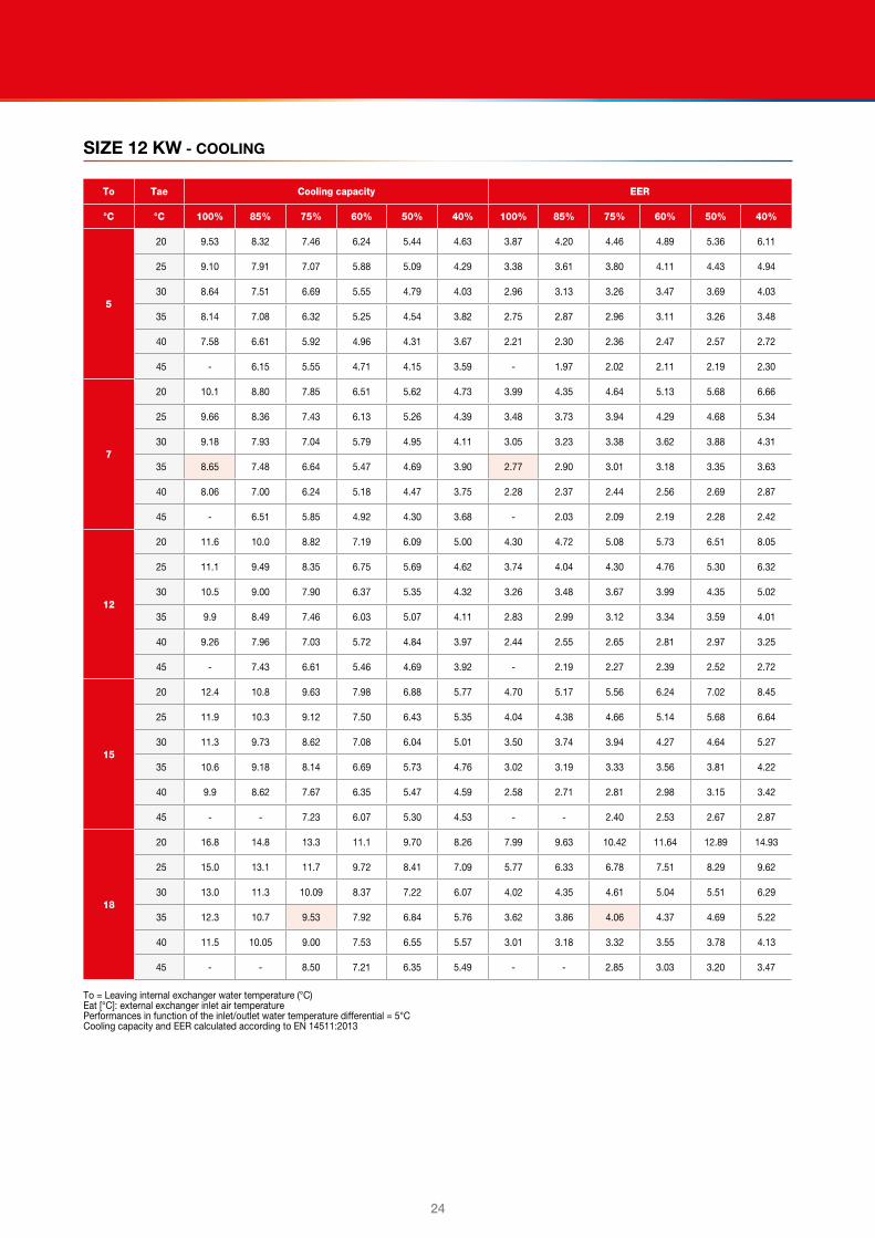
SIZE 12 KW - COOLING
To Tae Cooling capacity EER
°C °C 100% 85% 75% 60% 50% 40% 100% 85% 75% 60% 50% 40%
5
20 9.53 8.32 7.46 6.24 5.44 4.63 3.87 4.20 4.46 4.89 5.36 6.11
25 9.10 7.91 7.07 5.88 5.09 4.29 3.38 3.61 3.80 4.11 4.43 4.94
30 8.64 7.51 6.69 5.55 4.79 4.03 2.96 3.13 3.26 3.47 3.69 4.03
35 8.14 7.08 6.32 5.25 4.54 3.82 2.75 2.87 2.96 3.11 3.26 3.48
40 7.58 6.61 5.92 4.96 4.31 3.67 2.21 2.30 2.36 2.47 2.57 2.72
45 - 6.15 5.55 4.71 4.15 3.59 - 1.97 2.02 2.11 2.19 2.30
7
20 10.1 8.80 7.85 6.51 5.62 4.73 3.99 4.35 4.64 5.13 5.68 6.66
25 9.66 8.36 7.43 6.13 5.26 4.39 3.48 3.73 3.94 4.29 4.68 5.34
30 9.18 7.93 7.04 5.79 4.95 4.11 3.05 3.23 3.38 3.62 3.88 4.31
35 8.65 7.48 6.64 5.47 4.69 3.90 2.77 2.90 3.01 3.18 3.35 3.63
40 8.06 7.00 6.24 5.18 4.47 3.75 2.28 2.37 2.44 2.56 2.69 2.87
45 - 6.51 5.85 4.92 4.30 3.68 - 2.03 2.09 2.19 2.28 2.42
12
20 11.6 10.0 8.82 7.19 6.09 5.00 4.30 4.72 5.08 5.73 6.51 8.05
25 11.1 9.49 8.35 6.75 5.69 4.62 3.74 4.04 4.30 4.76 5.30 6.32
30 10.5 9.00 7.90 6.37 5.35 4.32 3.26 3.48 3.67 3.99 4.35 5.02
35 9.9 8.49 7.46 6.03 5.07 4.11 2.83 2.99 3.12 3.34 3.59 4.01
40 9.26 7.96 7.03 5.72 4.84 3.97 2.44 2.55 2.65 2.81 2.97 3.25
45 - 7.43 6.61 5.46 4.69 3.92 - 2.19 2.27 2.39 2.52 2.72
15
20 12.4 10.8 9.63 7.98 6.88 5.77 4.70 5.17 5.56 6.24 7.02 8.45
25 11.9 10.3 9.12 7.50 6.43 5.35 4.04 4.38 4.66 5.14 5.68 6.64
30 11.3 9.73 8.62 7.08 6.04 5.01 3.50 3.74 3.94 4.27 4.64 5.27
35 10.6 9.18 8.14 6.69 5.73 4.76 3.02 3.19 3.33 3.56 3.81 4.22
40 9.9 8.62 7.67 6.35 5.47 4.59 2.58 2.71 2.81 2.98 3.15 3.42
45 - - 7.23 6.07 5.30 4.53 - - 2.40 2.53 2.67 2.87
18
20 16.8 14.8 13.3 11.1 9.70 8.26 7.99 9.63 10.42 11.64 12.89 14.93
25 15.0 13.1 11.7 9.72 8.41 7.09 5.77 6.33 6.78 7.51 8.29 9.62
30 13.0 11.3 10.09 8.37 7.22 6.07 4.02 4.35 4.61 5.04 5.51 6.29
35 12.3 10.7 9.53 7.92 6.84 5.76 3.62 3.86 4.06 4.37 4.69 5.22
40 11.5 10.05 9.00 7.53 6.55 5.57 3.01 3.18 3.32 3.55 3.78 4.13
45 - - 8.50 7.21 6.35 5.49 - - 2.85 3.03 3.20 3.47
To = Leaving internal exchanger water temperature (°C)Eat [°C]: external exchanger inlet air temperaturePerformances in function of the inlet/outlet water temperature differential = 5°CCooling capacity and EER calculated according to EN 14511:2013

2524
Just feel well
SIZE 14 KW - HEATING
To Tae (°C)DB/WB Heating capacity COP
°C °C 100% 90% 70% 50% 40% 100% 90% 70% 50% 40%
25
-20/-20.1 - - - - - - - - - -
-10/-10.5 8.53 7.87 6.17 4.37 3.40 2.83 2.93 3.08 3.24 3.38
-7/-8 9.51 8.73 6.95 5.13 4.15 3.15 3.26 3.43 3.61 3.75
0/-0.6 10.7 10.0 8.14 6.16 5.10 3.36 3.55 3.66 3.57 3.47
2/1.1 11.4 10.6 8.63 6.53 5.40 3.52 3.62 3.81 4.04 4.21
7/6 14.5 13.1 10.5 8.3 7.16 4.34 4.52 4.80 5.08 5.28
12/10.2 16.5 14.7 12.0 9.3 7.93 4.69 5.28 5.48 5.83 6.08
15/13 17.9 16.1 13.0 10.0 8.5 5.05 5.48 5.93 6.33 6.61
20/16 20.1 18.4 14.6 11.2 9.3 5.66 5.77 6.67 7.18 7.53
35
-20/-20.1 - - - 2.56 1.93 - - - 1.92 2.09
-10/-10.5 8.15 7.50 5.88 4.16 3.23 2.43 2.50 2.64 2.79 2.92
-7/-8 9.14 8.38 6.67 4.92 3.98 2.72 2.81 2.96 3.13 3.26
0/-0.6 10.6 9.8 7.99 6.05 5.01 2.98 3.13 3.24 3.17 3.08
2/1.1 11.2 10.4 8.48 6.42 5.31 3.14 3.21 3.38 3.60 3.75
7/6 14.3 12.9 10.5 8.3 7.12 3.91 4.06 4.33 4.59 4.78
12/10.2 16.16 14.34 11.68 9.11 7.74 4.16 4.64 4.82 5.14 5.37
15/13 17.5 15.8 12.7 9.8 8.3 4.48 4.83 5.20 5.57 5.83
20/16 19.8 18.2 14.4 11.0 9.2 4.99 5.09 5.84 6.30 6.61
45
-20/-20.1 - - - 2.88 2.17 - - - 1.80 1.94
-10/-10.5 8.04 7.38 5.77 4.08 3.17 1.96 2.00 2.11 2.26 2.36
-7/-8 8.65 7.91 6.27 4.63 3.75 2.09 2.14 2.26 2.41 2.51
0/-0.6 9.90 9.18 7.44 5.63 4.66 2.34 2.43 2.52 2.49 2.44
2/1.1 10.6 9.8 7.97 6.04 4.99 2.47 2.50 2.64 2.83 2.96
7/6 13.6 12.4 10.1 8.0 6.87 3.02 3.14 3.37 3.62 3.78
12/10.2 14.80 13.46 10.84 8.46 7.18 3.45 3.50 3.74 4.03 4.21
15/13 16.2 14.6 11.7 9.1 7.7 3.61 3.75 4.03 4.33 4.54
20/16 18.4 16.5 13.2 10.1 8.5 3.84 4.14 4.49 4.85 5.10
55
-20/-20.1 - - - - - - - - - -
-10/-10.5 8.16 7.43 5.77 4.08 3.18 1.49 1.52 1.59 1.68 1.75
-7/-8 8.59 7.80 6.15 4.54 3.67 1.56 1.59 1.66 1.76 1.82
0/-0.6 9.44 8.69 7.00 5.30 4.39 1.68 1.74 1.79 1.74 1.69
2/1.1 10.0 9.2 7.42 5.62 4.65 1.77 1.79 1.87 1.97 2.05
7/6 12.5 11.2 9.0 7.15 6.14 2.17 2.24 2.36 2.49 2.58
12/10.2 13.97 12.52 10.03 7.83 6.65 2.40 2.47 2.61 2.76 2.87
15/13 15.1 13.5 10.8 8.4 7.07 2.55 2.64 2.79 2.96 3.07
20/16 16.9 15.2 12.1 9.3 7.8 2.80 2.91 3.10 3.29 3.43
60
-20/-20.1 - - - - - - - - - -
-10/-10.5 - - - - - - - - - -
-7/-8 7.6 6.9 5.42 4.00 3.24 1.25 1.27 1.32 1.37 1.41
0/-0.6 9.4 8.6 6.90 5.22 4.32 1.51 1.56 1.59 1.53 1.48
2/1.1 10.0 9.2 7.38 5.59 4.62 1.60 1.62 1.67 1.75 1.80
7/6 12.7 11.3 9.1 7.19 6.17 2.01 2.05 2.14 2.24 2.30
12/10.2 14.24 12.71 10.14 7.92 6.72 2.22 2.28 2.38 2.50 2.57
15/13 15.4 13.7 10.9 8.5 7.16 2.36 2.44 2.56 2.68 2.76
20/16 17.3 15.5 12.3 9.4 7.9 2.60 2.69 2.84 2.98 3.08
To = Leaving internal exchanger water temperature (°C)Eat [°C]: external exchanger inlet air temperaturePerformances in function of the inlet/outlet water temperature differential = 5°CHeating capacity and COP calculated according to EN 14511:2013ATTENTION: The data of the heat capacity and COP include defrostings.DB = dry bulbWB = wet bulb

26
SIZE 14 KW - COOLING
To Tae Cooling capacity EER
°C °C 100% 80% 75% 60% 50% 40% 100% 80% 75% 60% 50% 40%
5
20 12.3 10.1 9.6 8.04 6.82 5.60 3.28 3.66 3.78 4.18 4.57 5.24
25 11.6 9.6 9.11 7.58 6.40 5.21 2.86 3.15 3.24 3.52 3.79 4.25
30 11.0 9.09 8.61 7.16 6.02 4.89 2.50 2.73 2.79 2.99 3.18 3.49
35 10.3 8.55 8.10 6.74 5.68 4.62 2.33 2.50 2.54 2.69 2.82 3.03
40 9.6 7.99 7.58 6.34 5.38 4.41 1.84 1.98 2.01 2.11 2.21 2.35
45 - 7.42 7.06 5.97 5.13 4.28 - 1.69 1.71 1.80 1.88 1.99
7
20 13.2 10.9 10.3 8.59 7.23 5.87 3.55 4.01 4.15 4.62 5.07 5.89
25 12.5 10.3 9.8 8.09 6.77 5.45 3.09 3.45 3.55 3.89 4.20 4.76
30 11.8 9.8 9.25 7.64 6.38 5.11 2.71 2.99 3.06 3.29 3.51 3.89
35 11.1 9.22 8.71 7.20 6.02 4.83 2.46 2.67 2.73 2.89 3.05 3.30
40 10.3 8.62 8.16 6.78 5.70 4.62 2.00 2.17 2.21 2.33 2.44 2.61
45 - 8.02 7.61 6.40 5.45 4.50 - 1.85 1.89 1.99 2.08 2.21
12
20 15.5 12.8 12.1 9.9 8.24 6.52 4.23 4.90 5.09 5.73 6.34 7.51
25 14.7 12.2 11.5 9.37 7.72 6.06 3.68 4.21 4.34 4.80 5.23 6.03
30 13.8 11.5 10.9 8.84 7.26 5.68 3.22 3.63 3.73 4.05 4.35 4.89
35 13.0 10.9 10.2 8.34 6.86 5.38 2.78 3.11 3.18 3.40 3.61 3.98
40 12.2 10.2 9.61 7.87 6.52 5.16 2.39 2.65 2.70 2.87 3.02 3.27
45 - 9.51 9.00 7.45 6.24 5.04 - 2.27 2.31 2.45 2.57 2.77
15
20 16.6 13.9 13.1 10.9 9.18 7.44 4.49 5.28 5.49 6.20 6.87 8.08
25 15.7 13.2 12.5 10.3 8.60 6.91 3.87 4.48 4.63 5.13 5.59 6.43
30 14.8 12.5 11.8 9.71 8.10 6.48 3.35 3.83 3.93 4.28 4.61 5.17
35 14.0 11.8 11.1 9.17 7.65 6.14 2.89 3.27 3.34 3.59 3.81 4.20
40 13.1 11.0 10.4 8.66 7.28 5.89 2.47 2.78 2.83 3.01 3.18 3.45
45 - - 9.78 8.21 6.98 5.75 - - 2.42 2.57 2.70 2.92
18
20 17.1 14.4 13.7 11.5 9.7 7.97 4.38 5.40 5.64 6.43 7.17 8.51
25 16.3 13.7 13.0 10.8 9.11 7.41 3.96 4.61 4.79 5.36 5.88 6.82
30 15.4 12.9 12.3 10.2 8.57 6.95 3.45 3.97 4.09 4.50 4.88 5.52
35 14.5 12.2 11.6 9.6 8.10 6.58 3.12 3.61 3.66 3.96 4.23 4.68
40 13.6 11.5 10.9 9.11 7.72 6.33 2.58 2.91 2.98 3.20 3.39 3.71
45 - - 10.2 8.66 7.43 6.19 - - 2.55 2.74 2.90 3.15
To = Leaving internal exchanger water temperature (°C)Eat [°C]: external exchanger inlet air temperaturePerformances in function of the inlet/outlet water temperature differential = 5°CCooling capacity and EER calculated according to EN 14511:2013

2726
Just feel well
SIZE 17 KW - HEATING
To Tae (°C)DB/WB Heating capacity COP
°C °C 100% 90% 70% 50% 40% 100% 90% 70% 50% 40%
25
-20/-20.1 - - - - - - - - - -
-10/-10.5 10.4 9.34 7.19 5.04 3.97 2.63 2.68 2.81 3.02 3.24
-7/-8 11.5 10.46 8.30 6.15 5.08 2.89 2.94 3.07 3.28 3.46
0/-0.6 13.0 11.8 9.57 7.32 6.19 3.22 3.29 3.44 3.65 3.83
2/1.1 13.9 12.7 10.24 7.83 6.63 3.45 3.52 3.69 3.92 4.12
7/6 17.7 16.2 13.5 10.9 9.57 4.19 4.39 4.63 4.92 5.13
12/10.2 19.8 18.2 14.8 11.8 10.30 4.69 4.77 5.37 5.56 5.84
15/13 21.6 19.9 16.2 12.7 11.0 5.10 5.19 5.61 6.06 6.37
20/16 24.6 22.6 18.6 14.2 12.2 5.79 5.89 5.97 6.92 7.33
35
-20/-20.1 - - - 3.14 2.37 - - - 2.11 2.38
-10/-10.5 10.09 9.04 6.96 4.88 3.85 2.48 2.53 2.64 2.80 2.96
-7/-8 11.2 10.16 8.06 5.98 4.94 2.71 2.76 2.89 3.05 3.19
0/-0.6 12.7 11.6 9.40 7.19 6.08 3.00 3.07 3.21 3.39 3.54
2/1.1 13.5 12.3 9.98 7.63 6.46 3.18 3.25 3.40 3.60 3.76
7/6 17.0 15.7 13.1 10.5 9.26 3.90 4.00 4.21 4.46 4.64
12/10.2 19.37 17.84 14.49 11.58 10.07 4.27 4.35 4.90 5.05 5.28
15/13 21.1 19.4 15.8 12.4 10.7 4.62 4.71 5.10 5.47 5.74
20/16 24.0 22.0 18.1 13.8 11.9 5.19 5.29 5.39 6.19 6.52
45
-20/-20.1 - - - 3.17 2.39 - - - 1.79 2.04
-10/-10.5 9.82 8.80 6.77 4.75 3.74 1.91 1.96 2.07 2.22 2.37
-7/-8 10.6 9.64 7.65 5.68 4.69 2.05 2.10 2.21 2.36 2.50
0/-0.6 12.3 11.25 9.10 6.96 5.89 2.31 2.37 2.50 2.67 2.82
2/1.1 13.2 12.0 9.70 7.42 6.28 2.45 2.51 2.66 2.84 2.99
7/6 16.7 15.4 12.8 10.3 9.08 3.02 3.11 3.29 3.52 3.69
12/10.2 18.70 17.23 14.10 11.17 9.71 3.27 3.35 3.64 3.91 4.11
15/13 20.1 18.5 15.1 11.9 10.2 3.49 3.58 3.88 4.18 4.41
20/16 22.5 20.7 16.8 13.0 11.1 3.86 3.95 4.27 4.65 4.93
55
-20/-20.1 - - - - - - - - - -
-10/-10.5 9.2 8.2 6.32 4.43 3.49 1.40 1.42 1.49 1.57 1.66
-7/-8 9.9 9.0 7.14 5.30 4.38 1.50 1.53 1.59 1.68 1.75
0/-0.6 11.5 10.5 8.49 6.49 5.50 1.69 1.73 1.80 1.90 1.98
2/1.1 12.2 11.1 9.00 6.89 5.83 1.79 1.82 1.90 2.01 2.09
7/6 15.3 14.1 11.8 9.5 8.34 2.20 2.24 2.34 2.47 2.56
12/10.2 17.19 15.83 12.95 10.26 8.92 2.39 2.43 2.59 2.74 2.85
15/13 18.5 17.0 13.9 10.9 9.41 2.55 2.60 2.76 2.93 3.05
20/16 20.7 19.0 15.4 11.9 10.2 2.81 2.87 3.05 3.25 3.40
60
-20/-20.1 - - - - - - - - - -
-10/-10.5 - - - - - - - - - -
-7/-8 10.0 9.0 7.18 5.32 4.40 1.40 1.42 1.46 1.53 1.58
0/-0.6 11.4 10.4 8.43 6.44 5.46 1.57 1.59 1.65 1.72 1.77
2/1.1 12.1 11.0 8.92 6.82 5.78 1.65 1.68 1.74 1.81 1.87
7/6 15.1 13.9 11.6 9.37 8.24 2.03 2.07 2.14 2.23 2.29
12/10.2 16.98 15.46 12.85 10.18 8.86 2.24 2.30 2.38 2.48 2.56
15/13 18.3 16.7 13.7 10.8 9.33 2.38 2.43 2.53 2.65 2.74
20/16 20.5 18.9 15.2 11.8 10.1 2.61 2.64 2.80 2.94 3.05
To = Leaving internal exchanger water temperature (°C)Eat [°C]: external exchanger inlet air temperaturePerformances in function of the inlet/outlet water temperature differential = 5°CHeating capacity and COP calculated according to EN 14511:2013ATTENTION: The data of the heat capacity and COP include defrostings.DB = dry bulbWB = wet bulb

28
SIZE 17 KW - COOLING
To Tae Cooling capacity EER
°C °C 100% 80% 75% 60% 50% 40% 100% 80% 75% 60% 50% 40%
5
20 17.7 16.3 13.9 11.79 10.32 8.84 4.13 4.33 4.64 5.11 5.48 6.05
25 16.8 15.6 13.17 11.06 9.63 8.19 3.54 3.64 3.93 4.26 4.52 4.91
30 16.1 14.77 12.44 10.42 9.05 7.68 3.01 3.12 3.35 3.58 3.76 4.02
35 15.0 13.67 11.52 9.66 8.40 7.14 2.58 2.64 2.80 2.95 3.07 3.24
40 13.6 12.50 10.58 8.93 7.81 6.68 2.16 2.22 2.33 2.44 2.52 2.64
45 - 11.24 9.62 8.21 7.26 6.31 - 1.84 1.93 2.01 2.08 2.16
7
20 18.4 16.9 14.4 12.06 10.49 8.91 4.13 4.33 4.77 5.29 5.71 6.36
25 17.5 16.1 13.6 11.31 9.78 8.25 3.55 3.67 4.04 4.40 4.70 5.15
30 16.7 15.3 12.80 10.65 9.19 7.72 3.04 3.19 3.44 3.70 3.90 4.20
35 15.5 14.15 11.87 9.88 8.54 7.19 2.62 2.71 2.89 3.06 3.19 3.39
40 14.1 12.92 10.88 9.11 7.92 6.72 2.21 2.27 2.39 2.51 2.61 2.74
45 - 11.74 9.99 8.47 7.44 6.41 - 1.90 2.00 2.09 2.17 2.27
12
20 20.2 18.4 15.4 12.8 10.93 9.09 4.12 4.35 5.09 5.73 6.26 7.14
25 19.1 17.4 14.5 11.94 10.17 8.39 3.58 3.75 4.32 4.77 5.14 5.75
30 18.1 16.5 13.7 11.21 9.52 7.83 3.13 3.36 3.68 3.99 4.25 4.66
35 16.7 15.4 12.7 10.43 8.87 7.31 2.70 2.90 3.11 3.33 3.50 3.77
40 15.3 14.0 11.61 9.58 8.20 6.81 2.33 2.41 2.56 2.70 2.82 3.00
45 - 12.99 10.91 9.11 7.89 6.66 - 2.06 2.18 2.30 2.39 2.53
15
20 22.0 20.2 16.9 14.3 12.46 10.57 4.29 4.54 5.01 5.96 6.53 7.43
25 20.8 19.0 16.0 13.4 11.56 9.73 3.72 3.90 4.47 4.96 5.36 5.98
30 19.6 17.9 15.1 12.53 10.80 9.06 3.24 3.37 3.81 4.15 4.42 4.84
35 18.2 16.8 14.1 11.71 10.11 8.49 2.78 2.96 3.21 3.45 3.63 3.91
40 16.7 15.4 12.9 10.83 9.40 7.96 2.42 2.52 2.69 2.85 2.98 3.17
45 - - 12.33 10.45 9.17 7.89 - - 2.33 2.47 2.57 2.72
18
20 25.2 23.1 19.6 16.7 14.6 12.56 4.88 5.19 5.77 6.76 7.53 8.64
25 23.7 21.7 18.3 15.5 13.50 11.50 4.22 4.45 4.88 5.69 6.20 6.96
30 22.1 20.2 17.0 14.4 12.53 10.64 3.65 3.82 4.14 4.76 5.11 5.63
35 20.5 18.8 15.9 13.4 11.67 9.93 3.13 3.26 3.64 3.96 4.20 4.54
40 18.8 17.3 14.8 12.49 10.93 9.37 2.67 2.77 3.08 3.30 3.47 3.71
45 - - 14.4 12.35 10.93 9.50 - - 2.74 2.93 3.07 3.27
To = Leaving internal exchanger water temperature (°C)Eat [°C]: external exchanger inlet air temperaturePerformances in function of the inlet/outlet water temperature differential = 5°CCooling capacity and EER calculated according to EN 14511:2013

2928
Just feel well
Recharge time of the PAC BT domestic hot water storage tank
Model Tae [°C)Recharge time Charge time
T1 [min] T2 [min] T3 [min] T4 [min] T5 [min] T6 [min]
PAC BT 5 kW
-5 39 68 100 193 226 265
7 28 49 71 139 163 187
30 24 40 61 106 123 155
PAC BT 7 kW
-5 29 51 73 146 171 194
7 21 37 53 105 123 141
30 19 31 43 80 93 108
PAC BT 9 kW
-5 22 40 55 111 132 145
7 16 29 40 82 97 105
30 16 26 34 65 78 84
PAC BT 12 kW
-5 17 29 44 87 98 116
7 13 22 32 65 73 84
30 15 16 24 54 54 62
PAC BT 14 kW
-5 14 23 36 71 78 95
7 11 19 26 56 63 69
30 13 18 23 47 50 55
PAC BT 17 kW
-5 12 20 28 59 67 74
7 9 15 22 46 51 58
30 11 15 20 39 42 47
Tae[°C] : external temperatureT1 [min]: recharge time with storage temperature at 38°C. Entering aqueduct water temperature 10°C - DHW set 45°CT2 [min]: recharge time with storage temperature at 38°C. Entering aqueduct water temperature 10°C - DHW set 50°CT3 [min]: recharge time with storage temperature at 38°C. Entering aqueduct water temperature 10°C - DHW set 55°CT4 [min]: recharge time with storage completely discharged. Entering aqueduct water temperature 10°C - DHW set 45°CT5 [min]: recharge time with storage completely discharged. Entering aqueduct water temperature 10°C - DHW set 50°CT6 [min]: recharge time with storage completely discharged. Entering aqueduct water temperature 10°C - DHW set 55°C
Accessories separately suppliedEvery accessory is marked with a configuration code, for instance CMMBX.
When the letter X is placed at the end, this means that the accessory is supplied separately. If there is no X in the code, the accessory is mounted in the factory.
7ACFH0818 - ADDITIONAL HEATER 2-4-6 KW
These are modulating electric heaters and can provide an additional capacity of 2-4-6 kW depending on the electrical connection performed.
Caution: When requesting them, you need to take into account the absorption of the additional 2-4-6 kW electric heater in relation to the absorption of the unit under nominal conditions to determine the dimensions of the mains and the metering device.
CONTROL
The electric heater has two different operating modes depending on the setting of a specific parameter:
1 The electric heater starts only when the capacity supplied by the heat pump is not enough to maintain the supply temperature requested by the climatic curve.
There is a minimum outdoor Temperature value (default value 2°C) above which the electric heater does not start.
2 Operation of the electric heater as a safety device, which is automatically activated if a fault occurs in the cooling circuit.

30
AMRX - RUBBER ANTIVIBRATION MOUNTS
■■ Outdoor unit
The rubber antivibration mounts reduce the vibrations of compressor during its operation and they are installed at the base toe.
A280X - AUXILIARY ACS STORAGE
If there is a higher demand for Domestic Hot Water, an additional 280L storage tank can be fitted into the design of PAC BT itself and with all the preset hydraulic connections.
The connection piping is set up according to the hydraulic diagram shown below, by placing the built-in storage tank in series with PAC BT’s storage tank.
The energy transfer between the two storage tanks is done via recirculation pump (5).
■■ Dimensions: 280L domestic hot water auxiliary storage cabinet: 600x2030x800
1 ACS user
2 Aqueduct inlet
3 Domestic water recirculation pump
4 Domestic hot water delivery connection (PAC BT to auxiliary storage)
5 Domestic hot water return (auxiliary storage to PAC BT)
■■ Distances to respected
A Joint storage tank
B Separate storage tank
C The spaces can be occupied by forniture or other objects; it has to be possible to move them easily in case of maintenance interventions.
Caution: Respect the unit functional clearances for maintenance
3130
Just feel well
PAC BT SOLAR (INTEGRATION DOMESTIC HOT WATER)
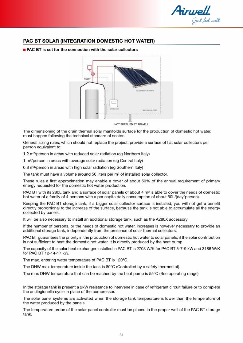
■■ PAC BT is set for the connection with the solar collectors
NOT SUPPLIED BY AIRWELL
The dimensioning of the drain thermal solar manifolds surface for the production of domestic hot water, must happen following the technical standard of sector.
General sizing rules, which should not replace the project, provide a surface of flat solar collectors per person equivalent to:
1.2 m²/person in areas with reduced solar radiation (eg Northern Italy)
1 m²/person in areas with average solar radiation (eg Central Italy)
0.8 m²/person in areas with high solar radiation (eg Southern Italy)
The tank must have a volume around 50 liters per m² of installed solar collector.
These rules a first approximation may enable a cover of about 50% of the annual requirement of primary energy requested for the domestic hot water production.
PAC BT with its 280L tank and a surface of solar panels of about 4 m² is able to cover the needs of domestic hot water of a family of 4 persons with a per capita daily consumption of about 50L/(day*person).
Keeping the PAC BT storage tank, if a bigger solar collector surface is installed, you will not get a benefit directly proportional to the increase of the surface, because the tank is not able to accumulate all the energy collected by panels.
It will be also necessary to install an additional storage tank, such as the A280X accessory
If the number of persons, or the needs of domestic hot water, increases is however necessary to provide an additional storage tank, independently from the presence of solar thermal collectors.
PAC BT guarantees the priority in the production of domestic hot water to solar panels; if the solar contribution is not sufficient to heat the domestic hot water, it is directly produced by the heat pump.
The capacity of the solar heat exchanger installed in PAC BT is 2703 W/K for PAC BT 5-7-9 kW and 3186 W/K for PAC BT 12-14-17 kW.
The max. entering water temperature of PAC BT is 120°C.
The DHW max temperature inside the tank is 80°C (Controlled by a safety thermostat).
The max DHW temperature that can be reached by the heat pump is 55°C (See operating range)
In the storage tank is present a 2kW resistance to intervene in case of refrigerant circuit failure or to complete the antilegionella cycle in place of the compressor.
The solar panel systems are activated when the storage tank temperature is lower than the temperature of the water produced by the panels.
The temperature probe of the solar panel controller must be placed in the proper well of the PAC BT storage tank.
PAC BT

32
■■ Solar exchanger pressure drops
DP = water side pressure drops (kPa)Q [l/s] = water flow-rate
A PAC BT size 5-7-9 kW
B PAC BT size 12-14-17 kW
■■ KCCEX - External boiler connection kit
1 External boiler connection kit
2 Costumer boiler
2 Pump to be provided by the Customer (required to compensate the boiler’s pressure drop)
The PAC BT control can manage an external boiler (provided by the Customer) with the following features:
q on/off with potential-free contact,q or with management of the supply temperature setpoint with signal 0-10V and on/off potential-free contact.
PAC BT’s control logic enables it to use the external boiler either as a supplementary unit or as a substitute
Caution: For further details, refer to the PAC BT Hybrid bulletin.

3332
Just feel well
Dimensional drawingsINDOOR UNIT
1 Domestic hot water outlet 1/2” GAS M
2 Aqueduct inlet 1/2” GAS M
3 Return from user side system 1”1/4 GAS M flat seat
4 User side system supply 1”1/4 GAS M flat seat
5 Gas line
6 Liquid line
7 Power input
8 Return from the 3/4” GAS M solar system (optional)
9 Supply to the 3/4” GAS M solar system (optional)
10 Dhw recirculation circuit inlet 3/8” GAS M
11 Automatic vent valve
12 Electronic anode
13 Boiler supply, gas M1”1/4 flat seat (optional)
14 Boiler return, gas M1”1/4 flat seat (optional)
15 Unit control keypad
16 Functional spaces
Size PAC BT from 5 to 9 kW PAC BT from 12 to 17 kW
Shipping height mm 2130 2130
Operating weight kg 450 470
Shipping weight kg 170 190
Important: For the refrigeration line diameters, refer to “Refrigerating line connections”.

34
OUTDOOR UNIT
■■ Size 5-7-9 kW
Functional clearances
1 Compressor compartment
2 Electrical panel
3 Power input
4 Electric fan
5 Liquid line fittings
6 Gas fittings
7 Condensate discharge connection Ø 13
8 Functional spaces
M Air supply
Size 5 kW 7 kW 9 kW
W1 supporting point kg 33 34 36
W2 Supporting point kg 16 17 19
W3 Supporting point kg 35 36 38
W4 Supporting point kg 18 18 20
Shipping height mm 1122 1122 1122
Operating weight kg 102 105 113
Shipping weight kg 104 107 115
Important: for the refrigeration line diameters, refer to “Refrigerating line connections”.

3534
Just feel well
■■ Size 12-14 kW
Functional clearances
1 Compressor compartment
2 Electrical panel
3 Power input
4 Electric fan
5 Liquid line fittings
6 Gas fittings
7 Condensate discharge connection Ø 13
8 Functional spaces
M Air supply
Size 12 kW 14 kW
W1 supporting point kg 45 47
W2 Supporting point kg 31 32
W3 Supporting point kg 50 49
W4 Supporting point kg 33 33
Shipping height mm 1364 1364
Operating weight kg 157 161
Shipping weight kg 160 164
Important: for the refrigeration line diameters, refer to “Refrigerating line connections”.
3, AVENUE DU CENTRE - LES QUADRANTS - BAT. A - 78280 GUYANCOURT, FRANCE
TEL: +33 (0)1 76 21 82 00 - FAX: +33 (0)1 76 21 82 01 - www.airwell-residential.com
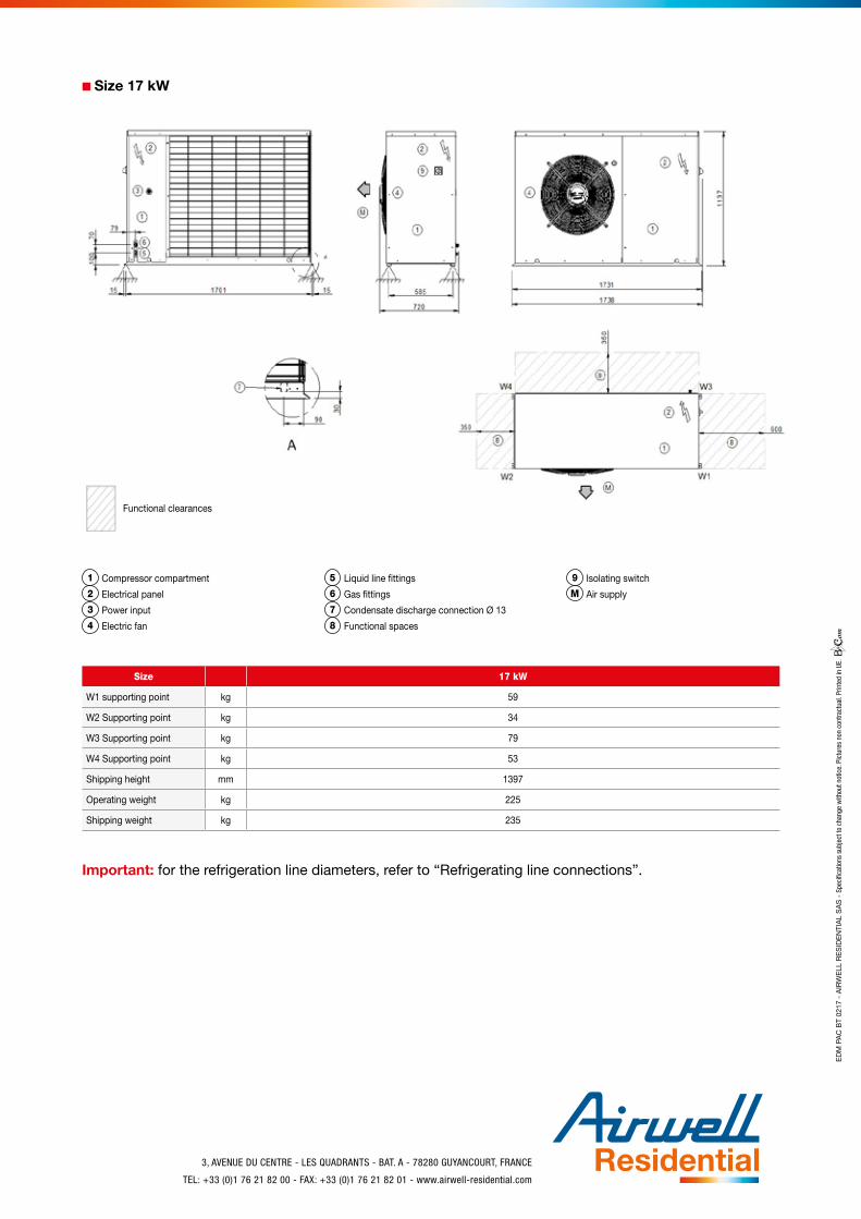
■■ Size 17 kW
Functional clearances
1 Compressor compartment
2 Electrical panel
3 Power input
4 Electric fan
5 Liquid line fittings
6 Gas fittings
7 Condensate discharge connection Ø 13
8 Functional spaces
9 Isolating switch
M Air supply
Size 17 kW
W1 supporting point kg 59
W2 Supporting point kg 34
W3 Supporting point kg 79
W4 Supporting point kg 53
Shipping height mm 1397
Operating weight kg 225
Shipping weight kg 235
Important: for the refrigeration line diameters, refer to “Refrigerating line connections”.
ED
M P
AC
BT
0217
- A
IRW
ELL
RE
SID
EN
TIA
L S
AS
- S
peci
ficat
ions
sub
ject
to c
hang
e w
ithou
t not
ice.
Pic
ture
s no
n co
ntra
ctua
l. Pr
inte
d in
UE.
![FLOW TEMP. CONTROLLER [MASTER] (Cased) PAC-IF051B-E PAC-IF052B-E FLOW TEMP. CONTROLLER ... · 2013. 2. 12. · PAC-IF051B-E PAC-IF052B-E FLOW TEMP. CONTROLLER [SLAVE] (Cased) PAC-SIF051B-E](https://static.fdocuments.in/doc/165x107/612d85651ecc515869423db7/flow-temp-controller-master-cased-pac-if051b-e-pac-if052b-e-flow-temp-controller.jpg)