PAC-6009 CARRIER G B S -...
21
Copyright 2017 Advantech Co. Ltd. All rights reserved. APPLICATION NOTE REVISION 1.01 DATE 2017/03/15 DEPLOYING OPENSTACK ON THE PAC-6009 CARRIER GRADE BLADE SERVER USING MIRANTIS 9.0
Transcript of PAC-6009 CARRIER G B S -...

Copyright 2017 Advantech Co. Ltd. All rights reserved.
APPLICATION NOTE
REVISION 1.01 DATE 2017/03/15
DEPLOYING OPENSTACK ON THE
PAC-6009 CARRIER GRADE BLADE SERVER
USING MIRANTIS 9.0
Copyright 2017 Advantech Co. Ltd. All rights reserved. Page 2 of 21
Revision History
Date [mm/dd/yyyy]
Revision Modifications
03/13/2017 1.0 First version
03/15/2017 1.01 Spelling errors & document layout issues corrected
© Copyright 2017 – Advantech Co., Ltd.
All Rights Reserved
Advantech Co., Ltd. reserves the right to make improvements in the products described in this manual at any time without notice. No part of this manual may be reproduced, copied, translated or transmitted in any form or by any means without the prior written permission of Advantech Co., Ltd. Information provided in this manual is intended to be accurate and reliable. However, Advantech Co., Ltd. assumes no responsibility for its use, nor for any infringements of the rights of third parties, which may result from its use.
Copyright 2017 Advantech Co. Ltd. All rights reserved. Page 3 of 21
Description This application note describes how to deploy OpenStack on the PAC-6009 Carrier Grade Blade Server using Mirantis 9.0. It is based on the standard process that Mirantis provides and highlights any additional steps required.
We appreciate your input
Please let us know if you consider any aspect of this application note needs improving or
correcting. We appreciate your valuable input in helping make our products and documentation
better.
Please send all such comments in writing to: [email protected]
Acknowledgements
Xeon and Intel are trademarked by Intel Corp.
Mirantis and FUEL are registered trademarks of Mirantis, Inc.
All other product names or trademarks are properties of their respective owners.

Copyright 2017 Advantech Co. Ltd. All rights reserved. Page 4 of 21
1. MIRANTIS UNLOCKS OPENSTACK
An open cloud is vital in helping enterprises and service providers compete in the software economy. With Mirantis OpenStack, you can build web scale clouds that unlock business agility.
Mirantis OpenStack consists of Core OpenStack services weaved into a proven HA reference architecture that can be managed with OpenStack native operations tooling. It can be extended with Fuel deployment plugins and validated drivers. And it can also be extended with Mirantis OpenStack plugins.
While the OpenStack community provides continuous integration (CI) testing, Mirantis provides a significantly higher level of testing. The packages are built from individual project repositories and are tested together using Mirantis reference architectures to ensure that these various software pieces work bug-free as a whole.
The scope of Mirantis testing also explains why customers are increasingly moving away from a do-it-yourself (DIY) approach and moving to Mirantis OpenStack. It is very hard for a single customer to test subsequently fix bugs at the same level of intensity.
Integration with Fuel for deployment and relevant onsite cluster health checks is also a critical piece of the overall hardening story.
Fuel is a leading purpose-built open source deployment and management tool for OpenStack. Developed as an OpenStack community effort, it provides an intuitive, GUI-driven experience for automated deployment and management of OpenStack, related community projects and plugins.
https://www.mirantis.com/products/mirantis-openstack-software/openstack-deployment-fuel/
Copyright 2017 Advantech Co. Ltd. All rights reserved. Page 5 of 21
2. E QUIPMENT SETUP
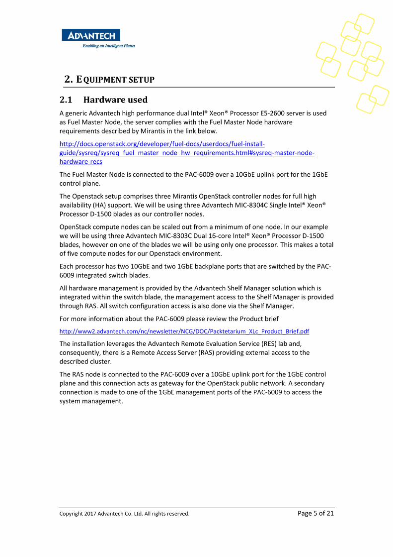
2.1 Hardware used
A generic Advantech high performance dual Intel® Xeon® Processor E5-2600 server is used as Fuel Master Node, the server complies with the Fuel Master Node hardware requirements described by Mirantis in the link below.
http://docs.openstack.org/developer/fuel-docs/userdocs/fuel-install-guide/sysreq/sysreq_fuel_master_node_hw_requirements.html#sysreq-master-node-hardware-recs
The Fuel Master Node is connected to the PAC-6009 over a 10GbE uplink port for the 1GbE control plane.
The Openstack setup comprises three Mirantis OpenStack controller nodes for full high availability (HA) support. We will be using three Advantech MIC-8304C Single Intel® Xeon® Processor D-1500 blades as our controller nodes.
OpenStack compute nodes can be scaled out from a minimum of one node. In our example we will be using three Advantech MIC-8303C Dual 16-core Intel® Xeon® Processor D-1500 blades, however on one of the blades we will be using only one processor. This makes a total of five compute nodes for our Openstack environment.
Each processor has two 10GbE and two 1GbE backplane ports that are switched by the PAC-6009 integrated switch blades.
All hardware management is provided by the Advantech Shelf Manager solution which is integrated within the switch blade, the management access to the Shelf Manager is provided through RAS. All switch configuration access is also done via the Shelf Manager.
For more information about the PAC-6009 please review the Product brief
http://www2.advantech.com/nc/newsletter/NCG/DOC/Packtetarium_XLc_Product_Brief.pdf
The installation leverages the Advantech Remote Evaluation Service (RES) lab and, consequently, there is a Remote Access Server (RAS) providing external access to the described cluster.
The RAS node is connected to the PAC-6009 over a 10GbE uplink port for the 1GbE control plane and this connection acts as gateway for the OpenStack public network. A secondary connection is made to one of the 1GbE management ports of the PAC-6009 to access the system management.
Copyright 2017 Advantech Co. Ltd. All rights reserved. Page 6 of 21
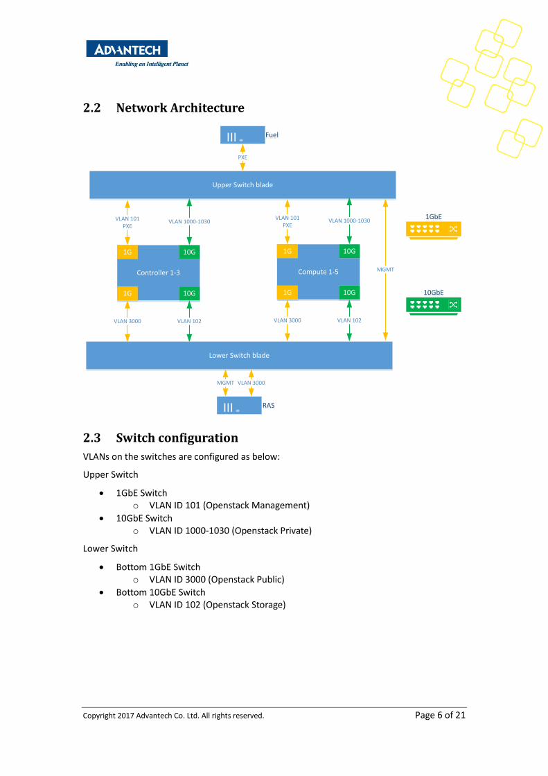
2.2 Network Architecture
1GbE1GbE
Controller 1-3
1G
1G
10G
10G
VLAN 1000-1030
VLAN 102
10GbE10GbE
RASRAS
FuelFuel
Upper Switch blade
Lower Switch blade
VLAN 101PXE
VLAN 3000
Compute 1-5
1G
1G
10G
10G
VLAN 1000-1030
VLAN 102
VLAN 101PXE
VLAN 3000
PXE
VLAN 3000MGMT
MGMT
2.3 Switch configuration
VLANs on the switches are configured as below:
Upper Switch
1GbE Switch o VLAN ID 101 (Openstack Management)
10GbE Switch o VLAN ID 1000-1030 (Openstack Private)
Lower Switch
Bottom 1GbE Switch o VLAN ID 3000 (Openstack Public)
Bottom 10GbE Switch o VLAN ID 102 (Openstack Storage)
Copyright 2017 Advantech Co. Ltd. All rights reserved. Page 7 of 21
3. PREPARING THE PAC-6009
All configuration settings will go through the active Shelf Manager in the system. To access the active Shelf Manager please connect one of the management ports to your management network. In our scenario we connected the upper switch management port to RAS.
SSH to the Management IP that was set on the system, if no Management IP was set on the system please find the instructions in the PAC-6009 users manual how to set this.
After we login to the active Shelf Manager there here is a snapshot of the different commands we will use
CLI – this gives us access to the command line interface of the hardware mgmt
solclient – this will give us access to the serial console of all blades
telnet 192.168.1.1 – this will give us access to the upper switch 1GbE management
telnet 192.168.1.2 – this will give us access to the lower switch 1GbE management
telnet 192.168.1.251 – this will give us access to the upper switch 10GbE management
telnet 192.168.1.252 – this will give us access to the lower switch 1GbE management
3.1 Setting up switch configuration
3.1.1 Configure VLAN upper 1GbE switch
1. Access the upper 1GbE switch # telnet 192.168.1.1
2. Use the user credentials provided in the PAC-6009 switch manual to login 3. Enable switch configuration
(ESM-9578) >en 4. Enter vlan database
(ESM-9578) #vlan database 5. Create vlan 101
(ESM-9578) (Vlan)#vlan 101 6. You can see the vlan database by using the command “show vlan” 7. Exit the vlan database
(ESM-9578) (Vlan)#exit 8. Enter the configuration mode
(ESM-9578) #configure 9. Select all 18 backplane interfaces, for more details of the switch port configuration
please see the PAC-6009 switch users manual. (ESM-9578) (Config)#interface 1/0/1-1/0/18
10. Include interfaces in vlan 101 (ESM-9578) (Interface 1/0/1-1/0/18)#vlan participation include 101
11. Enable vlan tagging for vlan 101 (ESM-9578) (Interface 1/0/1-1/0/18)#vlan tagging 101
12. Exit out of the interface selection and configuration mode (ESM-9578) (Interface 1/0/1-1/0/18)#exit (ESM-9578) (Config)#exit
13. Quit the session, when asked to save configuration you can choose yes if you would like to retain the configuration upon switch reset. (ESM-9578) #quit

Copyright 2017 Advantech Co. Ltd. All rights reserved. Page 8 of 21
3.1.2 Configure VLAN lower 1GbE switch
1. Access the lower 1GbE switch # telnet 192.168.1.2
2. Use the user credentials provided in the PAC-6009 switch manual to login 3. Enable switch configuration
(ESM-9578) >en 4. Enter vlan database
(ESM-9578) #vlan database 5. Create vlan 3000
(ESM-9578) (Vlan)#vlan 3000 6. You can see the vlan database by using the command “show vlan” 7. Exit the vlan database
(ESM-9578) (Vlan)#exit 8. Enter the configuration mode
(ESM-9578) #configure 9. Select all 18 backplane interfaces and the front panel 10GbE port connected to RAS,
for more details of the switch port configuration please see the PAC-6009 switch users manual. (ESM-9578) (Config)#interface 1/0/1-1/0/18,1/0/41
10. Include interfaces in vlan 3000 (ESM-9578) (Interface 1/0/1-1/0/18,1/0/41)#vlan participation include 3000
11. Enable vlan tagging for vlan 3000 (ESM-9578) (Interface 1/0/1-1/0/18,1/0/41)#vlan tagging 3000
12. Exit out of the interface selection and configuration mode (ESM-9578) (Interface 1/0/1-1/0/18 1/0/41)#exit (ESM-9578) (Config)#exit
13. Quit the session, when asked to save configuration you can choose yes if you would like to retain the configuration upon switch reset. (ESM-9578) #quit

Copyright 2017 Advantech Co. Ltd. All rights reserved. Page 9 of 21
3.1.3 Configure VLAN upper 10GbE switch
14. Access the upper 10GbE switch # telnet 192.168.1.251
15. Use the user credentials provided in the PAC-6009 switch manual to login 16. Enable switch configuration
(Advantech Switching) >en 17. Enter vlan database
(Advantech Switching) #vlan database 18. Create vlan 1000-1030
(Advantech Switching) (Vlan)#vlan 1000-1030 19. You can see the vlan database by using the command “show vlan” 20. Exit the vlan database
(Advantech Switching) (Vlan)#exit 21. Enter the configuration mode
(Advantech Switching) #configure 22. Select all 18 backplane interfaces, for more details of the switch port configuration
please see the PAC-6009 switch users manual. (Advantech Switching) (Config)#interface 1/0/1-1/0/18
23. Include interfaces in vlan 1000-1030 (Advantech Switching) (Interface 1/0/1-1/0/18)#vlan participation include 1000-1030
24. Enable vlan tagging for vlan 1000-1030 (Advantech Switching) (Interface 1/0/1-1/0/18)#vlan tagging 1000-1030
25. Exit out of the interface selection and configuration mode (Advantech Switching) (Interface 1/0/1-1/0/18)#exit (Advantech Switching) (Config)#exit
26. Quit the session, when asked to save configuration you can choose yes if you would like to retain the configuration upon switch reset. (Advantech Switching) #quit
Copyright 2017 Advantech Co. Ltd. All rights reserved. Page 10 of 21
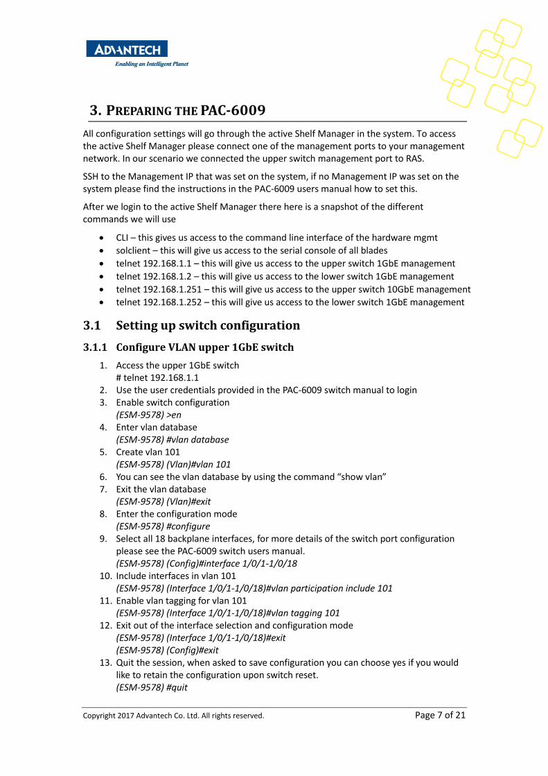
3.1.4 Configure VLAN lower 10GbE switch
27. Access the upper 10GbE switch # telnet 192.168.1.252
28. Use the user credentials provided in the PAC-6009 switch manual to login 29. Enable switch configuration
(Advantech Switching) >en 30. Enter vlan database
(Advantech Switching) #vlan database 31. Create vlan 102
(Advantech Switching) (Vlan)#vlan 102 32. You can see the vlan database by using the command “show vlan” 33. Exit the vlan database
(Advantech Switching) (Vlan)#exit 34. Enter the configuration mode
(Advantech Switching) #configure 35. Select all 18 backplane interfaces, for more details of the switch port configuration
please see the PAC-6009 switch users manual. (Advantech Switching) (Config)#interface 1/0/1-1/0/18
36. Include interfaces in vlan 1000-102 (Advantech Switching) (Interface 1/0/1-1/0/18)#vlan participation include 102
37. Enable vlan tagging for vlan 102 (Advantech Switching) (Interface 1/0/1-1/0/18)#vlan tagging 102
38. Exit out of the interface selection and configuration mode (Advantech Switching) (Interface 1/0/1-1/0/18)#exit (Advantech Switching) (Config)#exit
39. Quit the session, when asked to save configuration you can choose yes if you would like to retain the configuration upon switch reset. (Advantech Switching) #quit
Copyright 2017 Advantech Co. Ltd. All rights reserved. Page 11 of 21
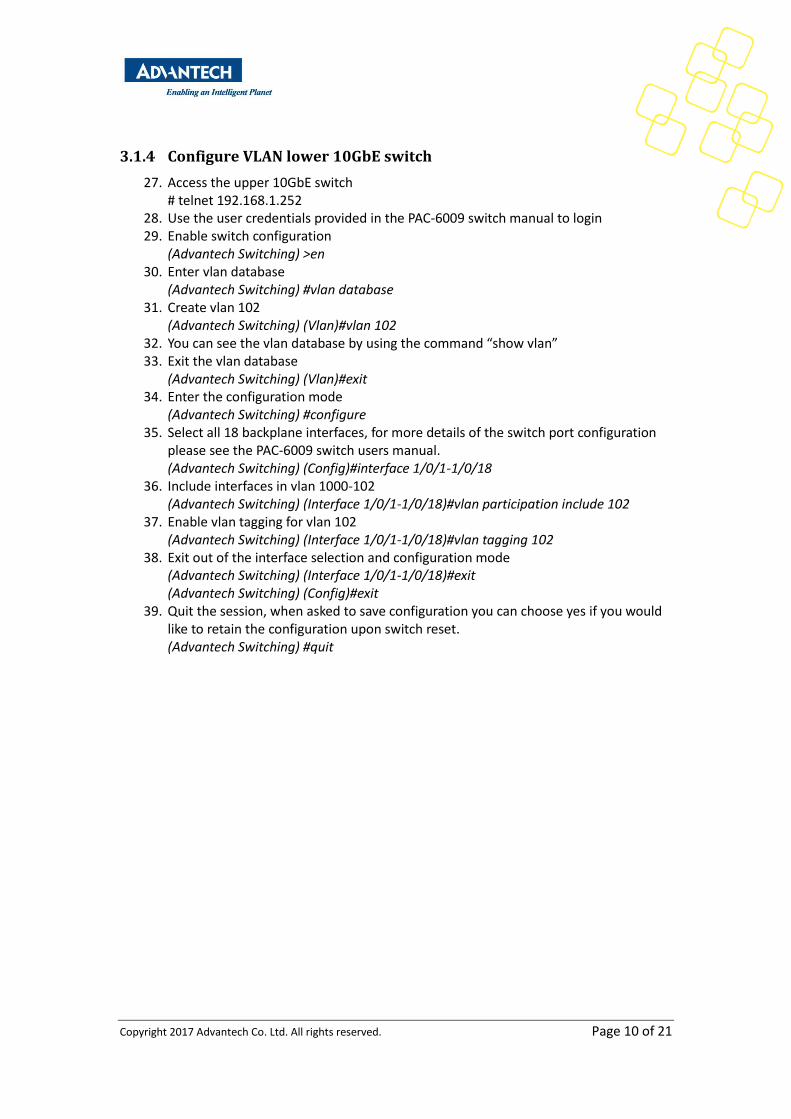
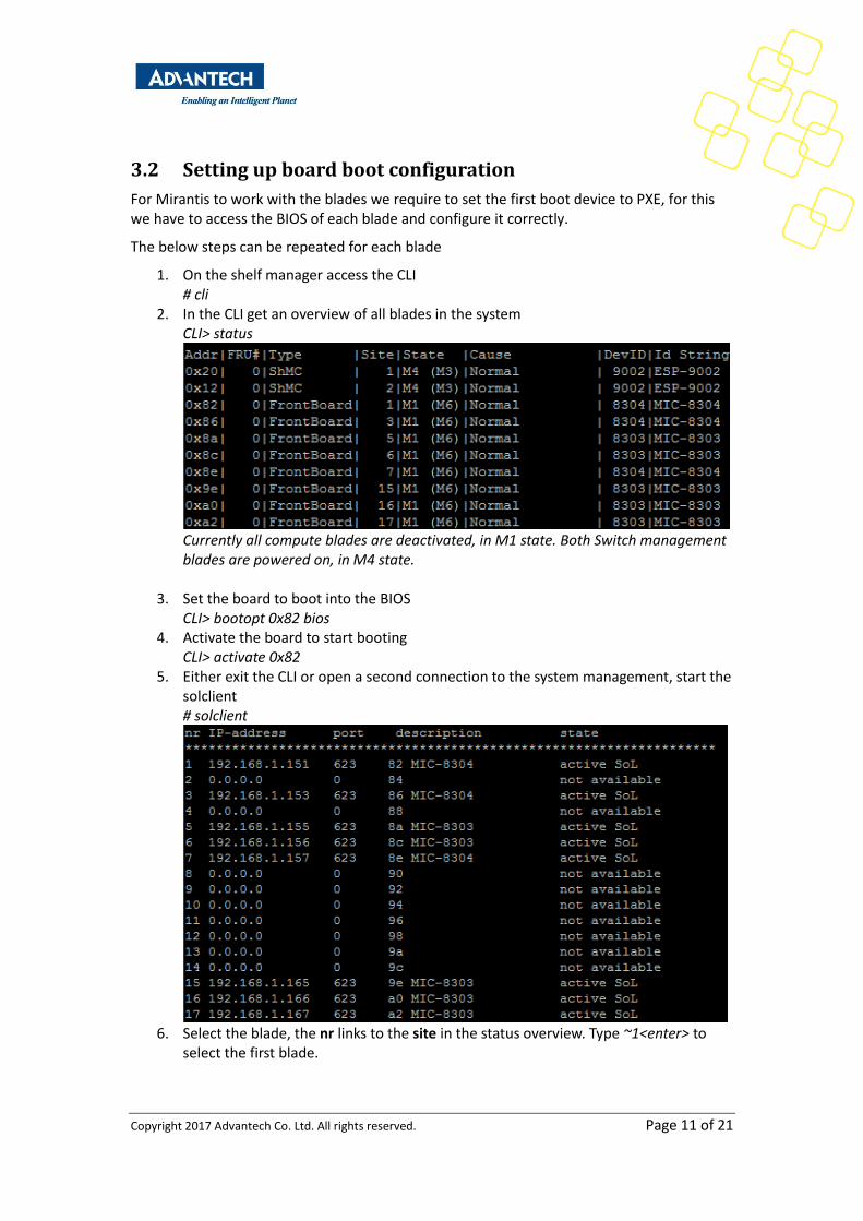
3.2 Setting up board boot configuration
For Mirantis to work with the blades we require to set the first boot device to PXE, for this we have to access the BIOS of each blade and configure it correctly.
The below steps can be repeated for each blade
1. On the shelf manager access the CLI # cli
2. In the CLI get an overview of all blades in the system CLI> status
Currently all compute blades are deactivated, in M1 state. Both Switch management blades are powered on, in M4 state.
3. Set the board to boot into the BIOS CLI> bootopt 0x82 bios
4. Activate the board to start booting CLI> activate 0x82
5. Either exit the CLI or open a second connection to the system management, start the solclient # solclient
6. Select the blade, the nr links to the site in the status overview. Type ~1<enter> to
select the first blade.
Copyright 2017 Advantech Co. Ltd. All rights reserved. Page 12 of 21
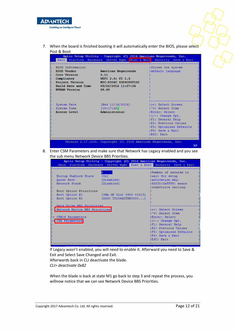
7. When the board is finished booting it will automatically enter the BIOS, please select Post & Boot
8. Enter CSM Parameters and make sure that Network has Legacy enabled and you see
the sub menu Network Device BBS Priorities.
If Legacy wasn’t enabled, you will need to enable it. Afterward you need to Save & Exit and Select Save Changed and Exit. Afterwards back in CLI deactivate the blade. CLI> deactivate 0x82 When the blade is back at state M1 go back to step 3 and repeat the process, you willnow notice that we can see Network Device BBS Priorities.
Copyright 2017 Advantech Co. Ltd. All rights reserved. Page 13 of 21
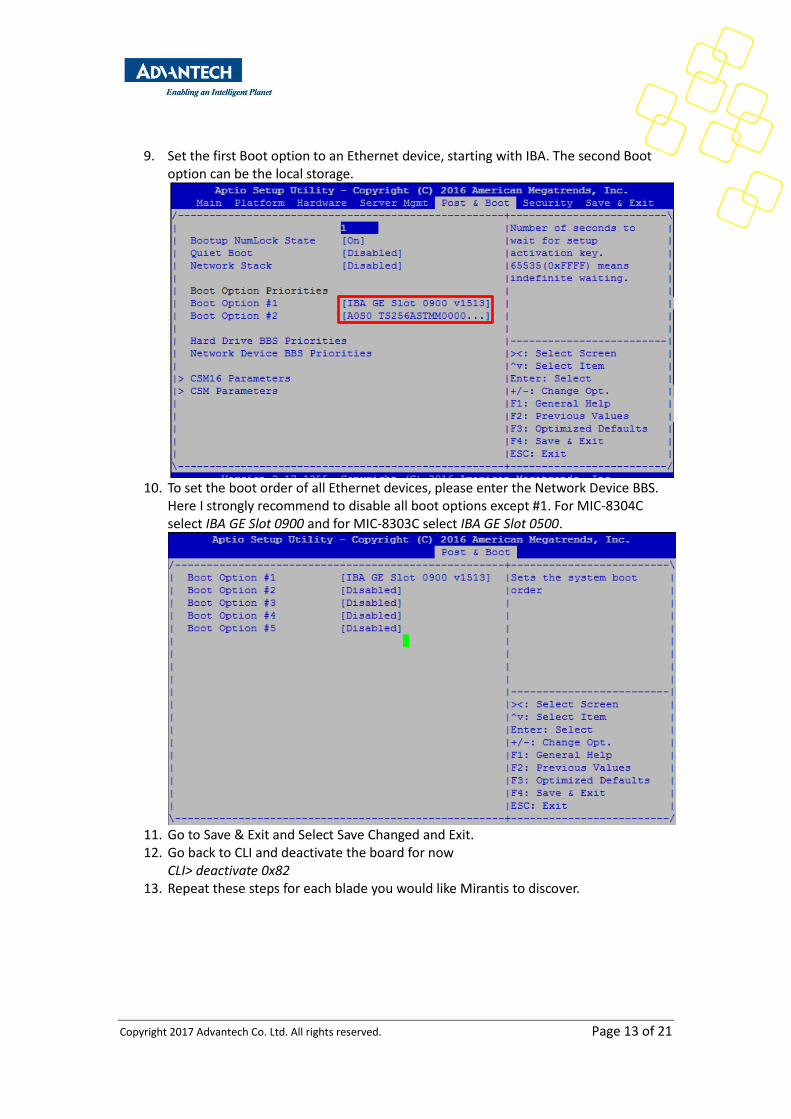
9. Set the first Boot option to an Ethernet device, starting with IBA. The second Boot option can be the local storage.
10. To set the boot order of all Ethernet devices, please enter the Network Device BBS.
Here I strongly recommend to disable all boot options except #1. For MIC-8304C select IBA GE Slot 0900 and for MIC-8303C select IBA GE Slot 0500.
11. Go to Save & Exit and Select Save Changed and Exit. 12. Go back to CLI and deactivate the board for now
CLI> deactivate 0x82 13. Repeat these steps for each blade you would like Mirantis to discover.
Copyright 2017 Advantech Co. Ltd. All rights reserved. Page 14 of 21
4. FUEL MASTER NODE INSTALLATION
The installation of the Mirantis 9.0 Fuel Master Node is based on the Mirantis Fuel install guide which can be found at the link below.
http://docs.openstack.org/developer/fuel-docs/userdocs/fuel-install-guide/install/install_install_fuel_master_node.html
4.1 Deploying Fuel Master Node over PXE
The Fuel Master Node is deployed over PXE. Details on how to do this can be found below. In this setup, the RAS server was used as a one-off PXE server.
https://docs.fuel-infra.org/fuel-dev/develop/pxe_deployment.html
4.2 Enable serial console for Fuel Master Node installation
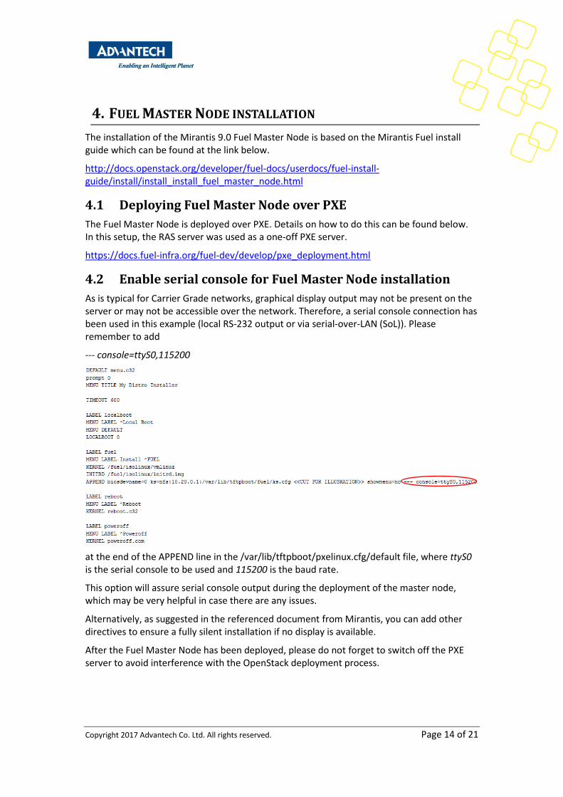
As is typical for Carrier Grade networks, graphical display output may not be present on the server or may not be accessible over the network. Therefore, a serial console connection has been used in this example (local RS-232 output or via serial-over-LAN (SoL)). Please remember to add
--- console=ttyS0,115200
at the end of the APPEND line in the /var/lib/tftpboot/pxelinux.cfg/default file, where ttyS0 is the serial console to be used and 115200 is the baud rate.
This option will assure serial console output during the deployment of the master node, which may be very helpful in case there are any issues.
Alternatively, as suggested in the referenced document from Mirantis, you can add other directives to ensure a fully silent installation if no display is available.
After the Fuel Master Node has been deployed, please do not forget to switch off the PXE server to avoid interference with the OpenStack deployment process.
Copyright 2017 Advantech Co. Ltd. All rights reserved. Page 15 of 21
5. PREPARING THE FUEL MASTER NODE
5.1 Updating the Bootstrap image
Login to the Fuel Master Node over SSH as described in:
http://docs.openstack.org/developer/fuel-docs/userdocs/fuel-install-guide/install/install_install_fuel_master_node.html
Mirantis 9.0 OpenStack is deployed using the default kernel that comes with Ubuntu 14.04 which does not have the right version of Intel’s ixgbe kernel module to support the Intel® Xeon® Processor D-1500. Mirantis has updated their repositories to include a DKMS package with Intel ixgbe kernel module version 4.4.6.
First we need to synchronize our local repository, which was installed from the ISO image, to the latest online version.
Please make sure your Fuel Master has Internet access and execute the following command, this will synchronize your local Mirantis repository with the latest online version.
fuel-createmirror --M
After this is completed you will have the ixgbe-dkms package in the following location
/var/www/nailgun/mirrors/mos-repos/ubuntu/9.0/pool/main/i/ixgbe-dkms/
We will need to build a new bootstrap image with an additional package, more information how to do this can be found here
http://docs.openstack.org/developer/fuel-docs/userdocs/fuel-install-guide/bootstrap/bootstrap_add_package.html
fuel-bootstrap --debug build --label 'ubuntu_14.04_with_ixgbe-dkms' --package 'ixgbe-dkms' --activate
After successfully completing the bootstrap image build, using fuel-boostrap --list will show the image and status is activate. This means newly discovered nodes will be booted with this boostrap image.
Note: If you desire to enable serial console for debug purpose in the bootstrap images please add the following to your build command.
--extend-kopts console=ttyS0,115200
If you deploy with a distribution other than Ubuntu and are using your own bootstrap images, please ensure that you have a kernel and modules that supports all the components inside the PAC-6009 Carrier Grade blade server. The latest lts-trusty kernel used by Ubuntu is 3.13.0-101, to be fully compatible with the Advantech MIC-8303C/8304C you require the Intel ixgbe kernel module version 4.2.5 or higher. This is tested and fully supported by the latest available hardware from Advantech.
More information about the different hardware components can be found on the Advantech website at the link below.
http://www.advantech.com/products/56622014-a73a-43fb-ad84-fec1e21f3f11/pac-6009/mod_f9d8e76b-bb6b-4e4b-9dca-953d6f94c01e
Copyright 2017 Advantech Co. Ltd. All rights reserved. Page 16 of 21
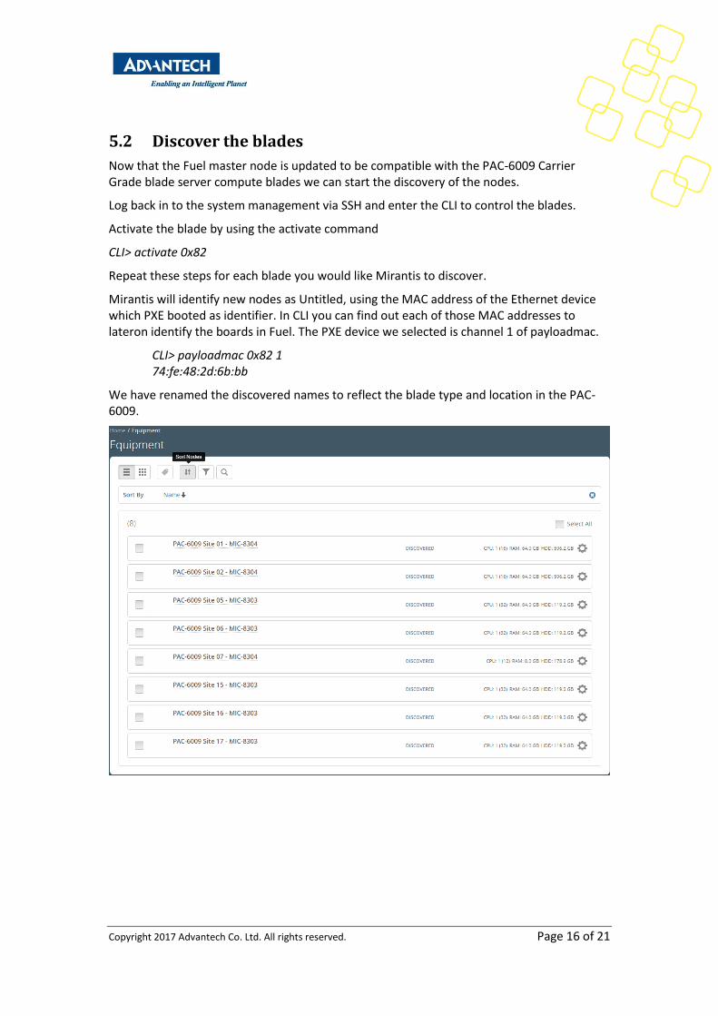
5.2 Discover the blades
Now that the Fuel master node is updated to be compatible with the PAC-6009 Carrier Grade blade server compute blades we can start the discovery of the nodes.
Log back in to the system management via SSH and enter the CLI to control the blades.
Activate the blade by using the activate command
CLI> activate 0x82
Repeat these steps for each blade you would like Mirantis to discover.
Mirantis will identify new nodes as Untitled, using the MAC address of the Ethernet device which PXE booted as identifier. In CLI you can find out each of those MAC addresses to lateron identify the boards in Fuel. The PXE device we selected is channel 1 of payloadmac.
CLI> payloadmac 0x82 1 74:fe:48:2d:6b:bb
We have renamed the discovered names to reflect the blade type and location in the PAC-6009.

Copyright 2017 Advantech Co. Ltd. All rights reserved. Page 17 of 21
6. CREATING A NEW OPENSTACK ENVIRONMENT
After all four systems have become available in the Fuel Master Node, a new OpenStack Environment can be created.
Following the user guide provided by Mirantis the deployment wizard is used as described in
http://docs.openstack.org/developer/fuel-docs/userdocs/fuel-user-guide/create-environment/start-create-env.html
The default settings for creating a new OpenStack environment have been used in this example. However, you could add additional items as described in the documentation provided by Mirantis.
6.1 Configuring the OpenStack environment
There are a lot of options when configuring the OpenStack environment. The linked document below provides a detailed explanation regarding how to perform an advanced configuration.
http://docs.openstack.org/developer/fuel-docs/userdocs/fuel-user-guide/configure-environment.html#configure-env-ug
Copyright 2017 Advantech Co. Ltd. All rights reserved. Page 18 of 21
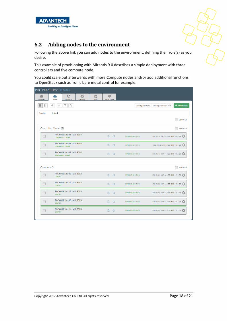
6.2 Adding nodes to the environment
Following the above link you can add nodes to the environment, defining their role(s) as you desire.
This example of provisioning with Mirantis 9.0 describes a simple deployment with three controllers and five compute node.
You could scale out afterwards with more Compute nodes and/or add additional functions to OpenStack such as Ironic bare metal control for example.
Copyright 2017 Advantech Co. Ltd. All rights reserved. Page 19 of 21
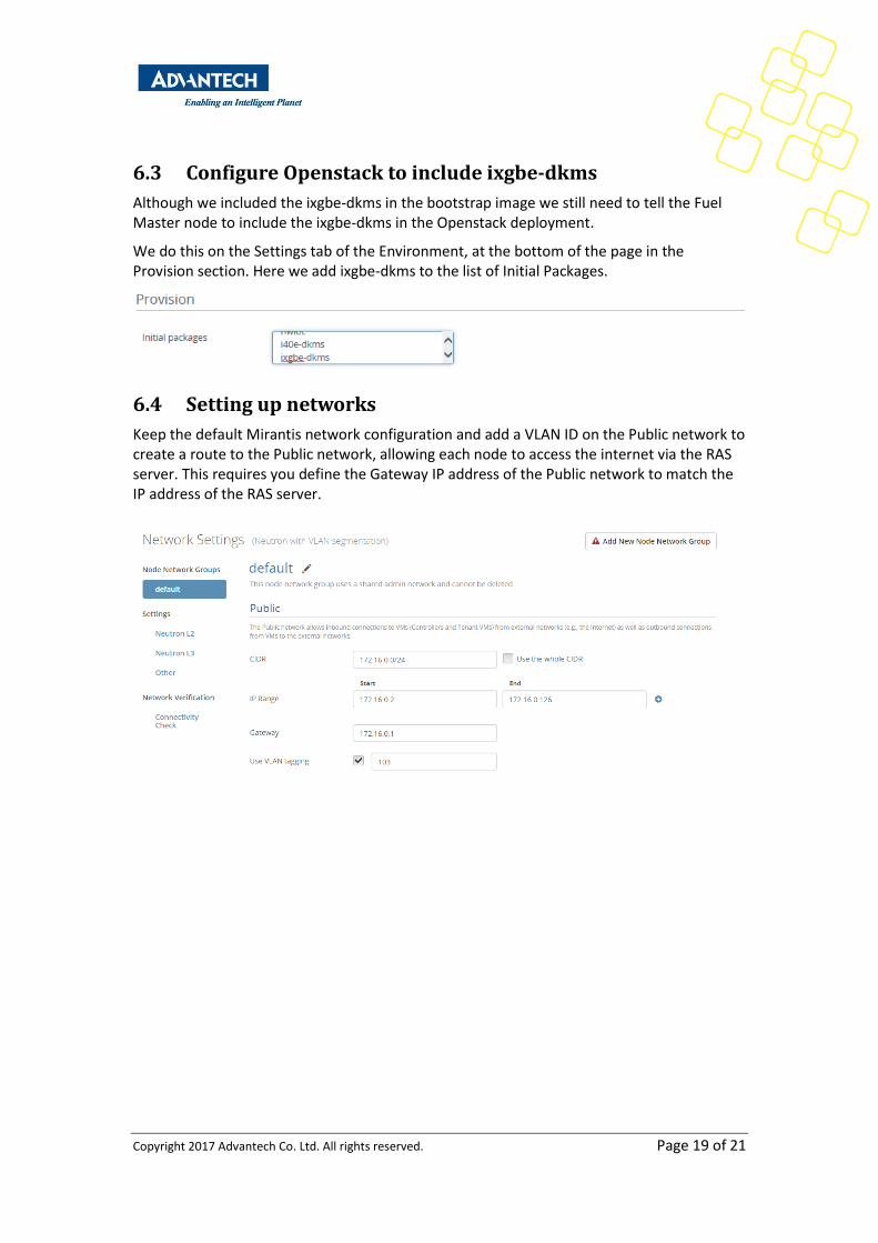
6.3 Configure Openstack to include ixgbe-dkms
Although we included the ixgbe-dkms in the bootstrap image we still need to tell the Fuel Master node to include the ixgbe-dkms in the Openstack deployment.
We do this on the Settings tab of the Environment, at the bottom of the page in the Provision section. Here we add ixgbe-dkms to the list of Initial Packages.
6.4 Setting up networks
Keep the default Mirantis network configuration and add a VLAN ID on the Public network to create a route to the Public network, allowing each node to access the internet via the RAS server. This requires you define the Gateway IP address of the Public network to match the IP address of the RAS server.
Copyright 2017 Advantech Co. Ltd. All rights reserved. Page 20 of 21
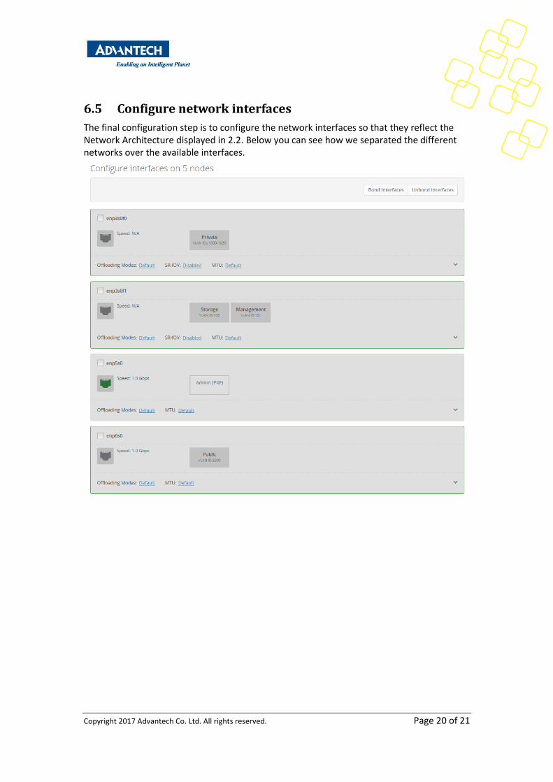
6.5 Configure network interfaces
The final configuration step is to configure the network interfaces so that they reflect the Network Architecture displayed in 2.2. Below you can see how we separated the different networks over the available interfaces.
Copyright 2017 Advantech Co. Ltd. All rights reserved. Page 21 of 21
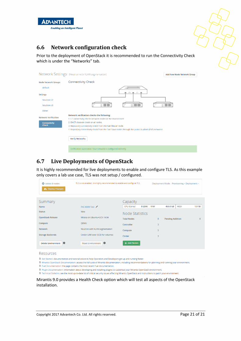
6.6 Network configuration check
Prior to the deployment of OpenStack it is recommended to run the Connectivity Check which is under the “Networks” tab.
6.7 Live Deployments of OpenStack
It is highly recommended for live deployments to enable and configure TLS. As this example only covers a lab use case, TLS was not setup / configured.
Mirantis 9.0 provides a Health Check option which will test all aspects of the OpenStack installation.