PA Series, PA Series, PA Series, PA Series, PA Series …...Palo Alto Networks Palo Alto Networks...
111
Corporate Headquarters Palo Alto Networks 3000 Tannery Way Santa Clara, CA 95054 Palo Alto Networks, Inc. www.paloaltonetworks.com © 2019 Palo Alto Networks, Inc. Palo Alto Networks is a registered trademark of Palo Alto Networks. A list of our trademarks can be found at http://www.paloaltonetworks.com/company/trademarks.html. All other marks mentioned herein may be trademarks of their respective companies. Non‐proprietary security policy may be reproduced only in its original entirety (without revision). Revision Date: July 18, 2019 PA‐200, PA‐220, PA‐220R, PA‐500, PA‐800 Series, PA‐3000 Series, PA‐3200 Series, PA‐ 5000 Series, PA‐5200 Series and PA‐7000 Series Firewalls Non‐Proprietary Security Policy
Transcript of PA Series, PA Series, PA Series, PA Series, PA Series …...Palo Alto Networks Palo Alto Networks...

Corporate Headquarters
Palo Alto Networks
3000 Tannery Way
Santa Clara, CA 95054
Palo Alto Networks, Inc.
www.paloaltonetworks.com
© 2019 Palo Alto Networks, Inc. Palo Alto Networks is a registered trademark of Palo Alto Networks. A list of our trademarks can be
found at http://www.paloaltonetworks.com/company/trademarks.html. All other marks mentioned herein may be trademarks of
their respective companies. Non‐proprietary security policy may be reproduced only in its original entirety (without revision).
Revision Date: July 18, 2019
PA‐200, PA‐220, PA‐220R, PA‐500, PA‐800 Series, PA‐3000 Series, PA‐3200 Series, PA‐5000 Series, PA‐5200 Series and PA‐7000 Series Firewalls Non‐Proprietary Security Policy

Palo Alto Networks
Palo Alto Networks Firewall Non-Proprietary Security Policy Page 2 of 111
Change Record
Table 1 ‐ Change Record
Date Author Description of Change
12/12/2018 A. Shahhosseini Initial authoring
5/31/2019 A. Shahhosseini Updates in response to CMVP comments
6/17/2019 A. Shahhosseini Updates in response to CMVP comments.
7/15/2019 A. Shahhosseini Updates in response to CMVP comments.
7/18/2019 A. Shahhosseini Updates in response to CMVP comments.

Palo Alto Networks
Palo Alto Networks Firewall Non-Proprietary Security Policy Page 3 of 111

Palo Alto Networks
Palo Alto Networks Firewall Non-Proprietary Security Policy Page 4 of 111
Contents 1 Module Overview ............................................................................................................................................ 8
2 Security Level ................................................................................................................................................. 12
3 Modes of Operation ....................................................................................................................................... 12
3.1 FIPS Approved Mode of Operation ...................................................................................................... 12
3.2 Non‐Approved Mode of Operation ...................................................................................................... 13
3.3 Approved and Allowed Algorithms ...................................................................................................... 14
3.4 Non‐Approved, Non‐Allowed Algorithms ............................................................................................ 18
4 Ports and Interfaces ....................................................................................................................................... 18
5 Identification and Authentication Policy ....................................................................................................... 38
5.1 Assumption of Roles ............................................................................................................................. 38
6 Access Control Policy ..................................................................................................................................... 40
6.1 Roles and Services ................................................................................................................................ 40
6.2 Unauthenticated Services .................................................................................................................... 41
6.3 Definition of Critical Security Parameters (CSPs) ................................................................................. 41
6.4 Definition of Public Keys....................................................................................................................... 43
6.5 Definition of CSPs Modes of Access ..................................................................................................... 45
7 Operational Environment .............................................................................................................................. 46
8 Security Rules ................................................................................................................................................. 46
8.1 FIPS 140‐2 Security Rules ..................................................................................................................... 46
8.2 Physical Security Mechanisms ............................................................................................................. 49
8.3 Operator Required Actions .................................................................................................................. 64
9 Mitigation of Other Attacks Policy ................................................................................................................. 65
10 Definitions and Acronyms .............................................................................................................................. 65
11 Reference Documents ................................................................................................................................... 66
12 Appendix A ‐ PA‐200 ‐ FIPS Accessories/Tamper Seal Installation (5 Seals) .................................................. 67
13 Appendix B ‐ PA‐220 ‐ FIPS Accessories/Tamper Seal Installation (6 Seals) .................................................. 70
14 Appendix C ‐ PA‐500 ‐ FIPS Accessories/Tamper Seal Installation (12 Seals) ................................................ 72
15 Appendix D ‐ PA‐800 series ‐ FIPS Accessories/Tamper Seal Installation (11 Seals) ..................................... 79
16 Appendix E ‐ PA‐3020 and PA‐3050 ‐ FIPS Accessories/Tamper Seal Installation (7 Seals) ........................... 82
17 Appendix F ‐ PA‐3060 ‐ FIPS Accessories/Tamper Seal Installation (8 Seals) ................................................ 85
18 Appendix G – PA‐3200 Series – FIPS Accessories/Tamper Seal Installation (19 Seals) ................................. 88
19 Appendix H ‐ PA‐5000 Series ‐ FIPS Accessories/Tamper Seal Installation (17 Seals) ................................... 90
20 Appendix I ‐ PA‐5200‐ FIPS Accessories/Tamper Seal Installation (28 Seals) ................................................ 93
21 Appendix J ‐ PA‐7050 ‐ FIPS Accessories/Tamper Seal Installation (24 Seals) ............................................... 96
22 Appendix K ‐ PA‐7080 ‐ FIPS Accessories/Tamper Seal Installation (10 Seals) ............................................ 106
23 Appendix L ‐ PA‐220R‐ FIPS Accessories/Tamper Seal Installation (5 Seals) ............................................... 111

Palo Alto Networks
Palo Alto Networks Firewall Non-Proprietary Security Policy Page 5 of 111
Tables
Table 1 ‐ Change Record .......................................................................................................................................... 2Table 2 ‐ Validated Version Information ................................................................................................................ 10Table 3 ‐ Module Security Level Specification ....................................................................................................... 12Table 4 ‐ FIPS Approved Algorithms Used in the Module ...................................................................................... 14Table 5 – FIPS Allowed Algorithms Used in the Module ........................................................................................ 17Table 6 ‐ Supported Protocols in FIPS Approved Mode ......................................................................................... 17Table 7 ‐ Non‐Approved Mode of Operation ......................................................................................................... 18Table 8 ‐ PA‐200 FIPS 140‐2 Ports and Interfaces .................................................................................................. 19Table 9 ‐ PA‐220 FIPS 140‐2 Ports and Interfaces .................................................................................................. 20Table 10 ‐ PA‐220R FIPS 140‐2 Ports and Interfaces .............................................................................................. 21Table 11 ‐ PA‐500 & PA‐500‐2GB FIPS 140‐2 Ports and Interfaces ........................................................................ 22Table 12 ‐ PA‐800 Series FIPS 140‐2 Ports and Interfaces ..................................................................................... 24Table 13 ‐ PA‐3000 Series FIPS 140‐2 Ports and Interfaces ................................................................................... 26Table 14 ‐ PA‐3200 Series FIPS 140‐2 Ports and Interfaces ................................................................................... 28Table 15 ‐ PA‐5000 Series FIPS 140‐2 Ports and Interfaces ................................................................................... 29Table 16 ‐ PA‐5200 Series FIPS 140‐2 Ports and Interfaces ................................................................................... 31Table 17 ‐ PA‐7050 FIPS 140‐2 Ports and Interfaces .............................................................................................. 34Table 18 ‐ PA‐7080 FIPS 140‐2 Ports and Interfaces .............................................................................................. 36Table 19 ‐ Roles and Required Identification and Authentication ......................................................................... 38Table 20 ‐ Strengths of Authentication Mechanisms ............................................................................................. 39Table 21 ‐ Authenticated Service Descriptions ...................................................................................................... 40Table 22 ‐ Authenticated Services ......................................................................................................................... 40Table 23 ‐ Unauthenticated Services ..................................................................................................................... 41Table 24 ‐ CSPs ....................................................................................................................................................... 41Table 25 ‐ Public Keys ............................................................................................................................................. 43Table 26 ‐ CSP and Public Key Access Rights within Roles & Services ................................................................... 45Table 27 ‐ Inspection/Testing of Physical Security Mechanisms ........................................................................... 64
Figures
Figure 1 ‐ Logical Diagram ...................................................................................................................................... 11Figure 2 ‐ PA‐200 Front Interfaces ......................................................................................................................... 19Figure 3 ‐ PA‐200 Rear Interfaces .......................................................................................................................... 19Figure 4 ‐ PA‐220 Front Interfaces ......................................................................................................................... 20Figure 5 ‐ PA‐220 Rear Interfaces .......................................................................................................................... 20Figure 6 ‐ PA‐220R Front Interfaces ....................................................................................................................... 21Figure 7 ‐ PA‐220R Rear Interfaces ........................................................................................................................ 21Figure 8 ‐ PA‐500 & PA‐500‐2GB Front Interfaces ................................................................................................. 22Figure 9 ‐ PA‐500 & PA‐500‐2GB Back Interfaces .................................................................................................. 22Figure 10 ‐ PA‐820 / PA‐850 Front Interfaces ........................................................................................................ 24

Palo Alto Networks
Palo Alto Networks Firewall Non-Proprietary Security Policy Page 6 of 111
Figure 11 ‐ PA‐820 Rear Interfaces ........................................................................................................................ 24Figure 12 ‐ PA‐850 Rear Interfaces ........................................................................................................................ 24Figure 13 ‐ PA‐3020 / PA‐3050 Front Interfaces .................................................................................................... 26Figure 14 ‐ PA‐3020 / PA‐3050 Back Interfaces ..................................................................................................... 26Figure 15 ‐ PA‐3060 Front Interfaces ..................................................................................................................... 26Figure 16 ‐ PA‐3060 Back Interfaces ...................................................................................................................... 26Figure 17 ‐ PA‐3200 Series Front Interfaces .......................................................................................................... 27Figure 18 ‐ PA‐3200 Series Rear Interfaces ............................................................................................................ 27Figure 19 ‐ PA‐5020 Front Interfaces ..................................................................................................................... 29Figure 20 ‐ PA‐5050/PA‐5060 Front Interfaces ...................................................................................................... 29Figure 21 ‐ PA‐5000 Series Back Interfaces ............................................................................................................ 29Figure 22 ‐ PA‐5200 Series Front Interfaces .......................................................................................................... 31Figure 23 ‐ PA‐5200 Rear Interfaces ...................................................................................................................... 31Figure 24 ‐ PA‐7050 Front Interfaces ..................................................................................................................... 33Figure 25 ‐ PA‐7050 Back Interfaces ...................................................................................................................... 33Figure 26 ‐ PA‐7080 Front (on Left) and Back (on Right) Interfaces ...................................................................... 36Figure 27 ‐ PA‐200 Left Side and Top Tamper Seal Placement (3) ......................................................................... 49Figure 28 ‐ PA‐200 Right Side Tamper Seal Placement (2) .................................................................................... 49Figure 29 ‐ PA‐220 Front with enclosure ............................................................................................................... 50Figure 30 – PA‐220 Right Side and Front Tamper Seal Placement (3) ................................................................... 50Figure 31 – PA‐220 Left Side and Front Tamper Seal Placement (3) ..................................................................... 50Figure 32 ‐ PA‐500 with Front Opacity Shield ........................................................................................................ 51Figure 33 ‐ PA‐500 Front Top Tamper Seal Placement (1) ..................................................................................... 51Figure 34 ‐ PA‐500 Left Side Tamper Seal Placement (3) ....................................................................................... 51Figure 35 ‐ PA‐500 Right Side Tamper Seal Placement (2) .................................................................................... 52Figure 36 ‐ PA‐500 Rear Tamper Seal Placement (6) ............................................................................................. 52Figure 37 ‐ PA‐3020 / PA‐3050 side with Opacity Shield ....................................................................................... 54Figure 38 ‐ PA‐3020/PA‐3050 Series Tamper Seal Placement (3) .......................................................................... 54Figure 39 ‐ PA‐3020/PA‐3050 Series Tamper Seal Placement (2) .......................................................................... 55Figure 40 ‐ PA‐3020/PA‐3050 Series Tamper Seal Placement (2) .......................................................................... 55Figure 41 – PA‐3060 Right side .............................................................................................................................. 55Figure 42 – PA‐3060 Left side ................................................................................................................................ 55Figure 43 – PA‐3060 Front/Top Tamper Seal Placement ....................................................................................... 56Figure 44 – PA‐3060 Front/Bottom Tamper Seal Placement ................................................................................. 56Figure 45 ‐ PA‐5000 Series Rear Tamper Seal Placement (9) with opacity shields ................................................ 56Figure 46 ‐ PA‐5000 Series Right Side Tamper Seal Placement (4) ........................................................................ 57Figure 47 ‐ PA‐5000 Series Left Side Tamper Seal Placement (4) .......................................................................... 57Figure 48 ‐ PA‐5200 Series front Opacity Shield .................................................................................................... 58Figure 49 ‐ PA‐5200 Series Left Side with Front Opacity Shield ............................................................................. 58Figure 50 ‐ PA‐5200 Series Right Side with Front Opacity Shield .......................................................................... 59Figure 51 ‐ PA‐5200 Series Rear Opacity Shield ..................................................................................................... 59

Palo Alto Networks
Palo Alto Networks Firewall Non-Proprietary Security Policy Page 7 of 111
Figure 52 ‐ PA‐7050 Front View with Opacity Shields ............................................................................................ 60Figure 53 ‐ PA‐7050 Rear View with Opacity Shields ............................................................................................. 60Figure 54 ‐ PA‐7050 Front and Right Side with Opacity Shields ............................................................................ 60Figure 55 ‐ PA‐7050 Rear and Left Side with Opacity Shields ................................................................................ 60Figure 56 ‐ PA‐7050 Tamper Seal Placement for Top Plenum (1‐4) ...................................................................... 61Figure 57 ‐ PA‐7050 Tamper Seal Placement for Bottom Plenum (5‐6) ................................................................ 61Figure 58 ‐ PA‐7050 Tamper Seal Placement for Rear (7‐20) ................................................................................ 62Figure 59 ‐ PA‐7050 Tamper Seal Placement for Top Plenum Bracket (21‐22) ..................................................... 62Figure 60 ‐ PA‐7050 Tamper Seal Placement for Bottom Plenum Bracket (23‐24) ............................................... 63Figure 61 ‐ PA‐7080 Front with Opacity Shield ...................................................................................................... 63Figure 62 ‐ PA‐7080 Rear ....................................................................................................................................... 63Figure 63 ‐ PA‐7080 Tamper Seal Placement on Left Side for Front Opacity Shield (1) ........................................ 64Figure 64 ‐ PA‐7080 Tamper Seal Placement on Right Side for Front Opacity Shield (1) ...................................... 64Figure 65 ‐ Top/Rear view of the PA‐220R ........................................................................................................... 111Figure 66 ‐ Bottom/Front view of the PA‐220R ................................................................................................... 111

Palo Alto Networks
Palo Alto Networks Firewall Non-Proprietary Security Policy Page 8 of 111
1 Module Overview
Palo Alto Networks offers a full line of next‐generation security appliances that range from the PA‐200, designed for enterprise remote offices, to the PA‐7080, which is a modular chassis designed for high‐speed datacenters. Our platform architecture is based on our single‐pass software engine, PAN‐OS, for networking, security, threat prevention, and management functionality that is consistent across all platforms. The devices differ only in capacities, performance, and physical configuration.
The Palo Alto Networks PA‐200, PA‐220, PA‐220R, PA‐500, PA‐800 Series, PA‐3000 Series, PA‐3200 Series, PA‐5000 Series, PA‐5200 Series, and PA‐7000 Series Firewalls (hereafter referred to as the modules) are multi‐chip standalone modules that provide network security by enabling enterprises to see and control applications, users, and content – not just ports, IP addresses, and packets – using three unique identification technologies: App‐ID, User‐ID, and Content‐ID. These identification technologies, found in Palo Alto Networks' enterprise firewalls, enable enterprises to create business‐relevant security policies – safely enabling organizations to adopt new applications, instead of the traditional “all‐or‐nothing” approach offered by traditional port‐blocking firewalls used in many security infrastructures.
Features and Benefits
Application visibility and control: Accurate identification of the applications traversing
the network enables policy‐based control over application usage at the firewall, the
strategic center of the security infrastructure.
Visualization tools: Graphical visibility tools, customizable reporting and logging enables
administrators to make a more informed decision on how to treat the applications
traversing the network.
Application browser: Helps administrators quickly research what the application is, its’
behavioral characteristics and underlying technology resulting in a more informed
decision making process on how to treat the application.
User‐based visibility and control: Seamless integration with enterprise directory services
(Active Directory, LDAP, eDirectory) facilitates application visibility and policy creation
based on user and group information, not just IP address. In Citrix and terminal services
environments, the identity of users sitting behind Citrix or terminal services can be used
to enable policy‐based visibility and control over applications, users and content. An XML
API enables integration with other, 3rd party user repositories.
Real‐time threat prevention: Detects and blocks application vulnerabilities, viruses,
spyware, and worms; controls web activity; all in real‐time, dramatically improving
performance and accuracy.

Palo Alto Networks
Palo Alto Networks Firewall Non-Proprietary Security Policy Page 9 of 111
File and data filtering: Taking full advantage of the in‐depth application inspection being
performed by App‐ID, administrators can implement several different types of policies
that reduce the risk associated with unauthorized file and data transfer.
Legacy firewall support: Support for traditional inbound and outbound port‐based
firewall rules mixed with application‐based rules smooth the transition to a Palo Alto
Networks next generation firewall.
Networking architecture: Support for dynamic routing (OSPF, RIP, BGP), virtual wire
mode and layer 2/layer 3 modes facilitates deployment in nearly any networking
environment.
Policy‐based Forwarding: Forward traffic based on policy defined by application, source
zone/interface, source/destination address, source user/group, and service.
Virtual Systems: Create multiple virtual “firewalls” within a single device as a means of
supporting specific departments or customers. Each virtual system can include dedicated
administrative accounts, interfaces, networking configuration, security zones, and policies
for the associated network traffic.
VPN connectivity: Secure site‐to‐site connectivity is enabled through standards‐based
IPSec VPN support while remote user access is delivered via SSL VPN connectivity.
Quality of Service (QoS): Deploy traffic shaping policies (guaranteed, maximum and
priority) to enable positive policy controls over bandwidth intensive, non‐work related
applications such as streaming media while preserving the performance of business
applications.
Real‐time bandwidth monitor: View real‐time bandwidth and session consumption for
applications and users within a selected QoS class.
Purpose‐built platform: combines single pass software with parallel processing hardware
to deliver the multi‐Gbps performance necessary to protect today’s high speed networks.

Palo Alto Networks
Palo Alto Networks Firewall Non-Proprietary Security Policy Page 10 of 111
The configurations for this validation are:
Table 2 ‐ Validated Version Information
Module Part Number Hardware Version
FIPS Kit Part Number FIPS Kit Hardware Version
FW
PA‐200 910‐000015 Rev. E 920‐000084 Rev. A
8.1.3 or 8.1.6
PA‐220 910‐000128 Rev. A 920‐000084 Rev. A
PA‐220R 910‐000147 Rev. B 920‐000226 Rev. A
PA‐500 910‐000006 Rev. O 920‐000005 Rev. A
PA‐500‐2GB 910‐000094 Rev. O 920‐000005 Rev. A
PA‐820 910‐000120 Rev. A 920‐000185 Rev. A
PA‐850 910‐000119 Rev. A 920‐000185 Rev. A
PA‐3020 910‐000017 Rev. J 920‐000081 Rev. A
PA‐3050 910‐000016 Rev. J 920‐000081 Rev. A
PA‐3060 910‐000104 Rev. C 920‐000138 Rev. A
PA‐3220 910‐000162 Rev. A 920‐000212 Rev. A
PA‐3250 910‐000163 Rev. A 920‐000212 Rev. A
PA‐3260 910‐000164 Rev. A 920‐000212 Rev. A
PA‐5020 910‐000010 Rev. F 920‐000037 Rev. A
PA‐5050 910‐000009 Rev. F 920‐000037 Rev. A
PA‐5060 910‐000008 Rev. F 920‐000037 Rev. A
PA‐5220 910‐000132 Rev. A 920‐000186 Rev. A
PA‐5250 910‐000131 Rev. A 920‐000186 Rev. A
PA‐5260 910‐000125 Rev. A 920‐000186 Rev. A
PA‐5280 910‐000157 Rev. A 920‐000186 Rev. A
PA‐7050 * 910‐000102 Rev. B 920‐000112 Rev. A

Palo Alto Networks
Palo Alto Networks Firewall Non-Proprietary Security Policy Page 11 of 111
PA‐7080 * 910‐000122 Rev. A 920‐000119 Rev. A
* Palo Alto Networks PA‐7000 Series firewalls are tested with four different Network Processing Cards (NPC), and any NPC may be configured for use in the Approved mode of operation.
PAN‐PA‐7000‐20G‐NPC: P/N: 910‐000028‐00B
PAN‐PA‐7000‐20GQ‐NPC: P/N: 910‐000117‐00A
PAN‐PA‐7000‐20GXM‐NPC: P/N: 910‐000137‐00A
PAN‐PA‐7000‐20GQXM‐NPC: P/N: 910‐000136‐00A
Figure 1 depicts the logical block diagram for the modules. The cryptographic boundary includes all of the logical components of the modules and the boundary is the physical enclosure of the firewall.
Figure 1 ‐ Logical Diagram

Palo Alto Networks
Palo Alto Networks Firewall Non-Proprietary Security Policy Page 12 of 111
2 Security Level
The cryptographic modules meet the overall requirements applicable to Level 2 security of FIPS 140‐2.
Table 3 ‐ Module Security Level Specification
Security Requirements Section Level
Cryptographic Module Specification 2
Module Ports and Interfaces 2
Roles, Services and Authentication 3
Finite State Model 2
Physical Security 2
Operational Environment N/A
Cryptographic Key Management 2
EMI/EMC 2
Self‐Tests 2
Design Assurance 3
Mitigation of Other Attacks N/A
3 Modes of Operation
3.1 FIPS Approved Mode of Operation
The modules support both a FIPS‐CC mode (FIPS Approved mode) and a Non‐Approved mode. The following procedure will put the modules into the FIPS‐approved mode of operation:
Install FIPS kit opacity shields and tamper evidence seals according to the Physical Security Policy
section. FIPS kits must be correctly installed to operate in the Approved mode of operation. The
tamper evidence seals and opacity shields shall be installed for the module to operate in a FIPS
Approved mode of operation.
During initial boot up, break the boot sequence via the console port connection (by pressing the
maint button when instructed to do so) to access the main menu.
Select “Continue.”
Select the “Set FIPS‐CC Mode” option to enter CC mode.
Select “Enable FIPS‐CC Mode”.

Palo Alto Networks
Palo Alto Networks Firewall Non-Proprietary Security Policy Page 13 of 111
When prompted, select “Reboot” and the module will re‐initialize and continue into CC mode (FIPS
mode).
The module will reboot.
In FIPS‐CC mode, the console port is available as a status output port.
The module will automatically indicate the FIPS Approved mode of operation in the following manner:
Status output interface will indicate “**** FIPS‐CC MODE ENABLED ****” via the CLI session.
Status output interface will indicate “FIPS‐CC mode enabled successfully” via the console port.
The module will display “FIPS‐CC” at all times in the status bar at the bottom of the web interface.
Should one or more power‐up self‐tests fail, the FIPS Approved mode of operation will not be achieved. Feedback will consist of:
The module will output “FIPS‐CC failure”
The module will reboot and enter a state in which the reason for the reboot can be determined.
To determine which self‐test caused the system to reboot into the error state, connect the console
cable and follow the on‐screen instructions to view the self‐test output.
3.2 Non‐Approved Mode of Operation
The following procedure will put the modules into the non‐Approved mode of operation:
Access the module’s CLI via SSH, and command the module to enter maintenance mode; the module will reboot
o Note: Establish a serial connection to the console port
After reboot, select “Continue.”
Select the “Set FIPS‐CC” option, and press enter.
Select “Disable FIPS‐CC Mode”, and press enter.
The module will disable FIPS‐CC mode, and perform a factory reset (zeroization)
Once complete, the module will provide the following status output:
o “Set FIPS‐CC Mode Status: Success”
The following procedure will zeroize the module:
Access the module’s CLI via SSH, and command the module to enter maintenance mode; the module will reboot
o Note: Establish a serial connection to the console port
After reboot, select “Continue.”
Select “Factory Reset”
The module will perform a zeroization, and provide the following message once complete:
o “Factory Reset Status: Success”

Palo Alto Networks
Palo Alto Networks Firewall Non-Proprietary Security Policy Page 14 of 111
3.3 Approved and Allowed Algorithms
The cryptographic modules support the following FIPS Approved algorithms in the Approved mode.
Table 4 ‐ FIPS Approved Algorithms Used in the Module
FIPS Approved Algorithm CAVP Cert. #
AES [FIPS 197, SP800‐38A]:
Functions: Encryption, Decryption
ECB, CBC, CTR modes; Encrypt/Decrypt; 128, 192 and 256‐bit
CFB128 mode; Encrypt/Decrypt; 128‐bit
Note: AES‐OFB, AES‐CFB1, AES‐CFB8 and AES‐CFB128 (192, 256 bit) were also tested but are not available for use
5890
AES‐CCM [SP800‐38C]: Encrypt and Decrypt, 128‐bit 5890
AES‐GCM [SP800‐38D]: Encrypt and Decrypt, 128 and 256‐bit (192 bit was tested but not available for use)
Note 1: GCM IV handling is compliant with FIPS IG A.5 and SP800‐38D.*
Note 2: GCM 192‐bit was tested, but it is not used by the module.
5890
CKG (SP800‐133) Key Generation Vendor Affirmed
‐ Asymmetric Key Generation; SP800‐133 §6, seed results from an unmodified DRBG output
‐ Symmetric Key Generation; SP800‐133 §7.1 (symmetric key results from an unmodified DRBG output), §7.2, and §7.3
Vendor Affirmed
CVL: Elliptic Curve Diffie‐Hellman Exchange [SP800‐56A]
‐ ECC CDH primitive (§5.7.1.2) Curves: P‐256, P‐384, P‐521
‐ KAS‐ECC all except KDF Curves: P‐256, P‐384, P‐521
2119
CVL: Diffie‐Hellman Exchange [SP800‐56A]
‐ KAS‐FFC all except KDF
Parameter Sets: FB and FC
2119
CVL: KDF, Application Specific [SP800‐135]
‐ TLS 1.0/1.1/1.2 KDF
‐ SNMPv3 KDF
‐ SSHv2 KDF
‐ IKE v1/v2 KDF
2120

Palo Alto Networks
Palo Alto Networks Firewall Non-Proprietary Security Policy Page 15 of 111
FIPS Approved Algorithm CAVP Cert. #
CVL: RSA [SP800‐56B]
‐ RSADP
2121
CVL: ECDSA Signature Generation
P‐256 SHA: SHA‐224, SHA‐256, SHA‐384, SHA‐512
P‐384 SHA: SHA‐224, SHA‐256, SHA‐384, SHA‐512
Note: P‐224 was tested, but not used by the module
2122
DRBG [SP800‐90A]: CTR DRBG with AES‐256, one instantiation per plane
Derivation function enabled
2451
DSA [FIPS 186‐4]: Key Generation (as prerequisite to CVL #2119)
‐Key Generation: 2048 bits
1485
ECDSA [FIPS 186‐4]
‐ Key Pair Generation P‐256, P‐384, and P‐521
‐ PKV P‐256, P‐384, and P‐521
‐ Signature Generation P‐256, P‐384 and P‐521; with all SHA‐2 sizes+
‐ Signature Verification P‐256, P‐384 and P‐521; with SHA‐1 and all SHA‐2 sizes+
Note: P‐224 was tested, but not used by the module
+Does not include the “short SHA‐512” sizes SHA‐512/224 or SHA‐512/256
1570
HMAC [FIPS 198]
‐ HMAC‐SHA‐1 with λ=96, 160
‐ HMAC‐SHA‐256 with λ=256
‐ HMAC‐SHA‐384 with λ=384
‐ HMAC‐SHA‐512 with λ=512
3865
KAS: SP 800‐56A Rev.2 Elliptic Curve Diffie‐Hellman Exchange (CVL Certs. #2119 and #2120, vendor affirmed; key agreement; key establishment methodology provides between 128 and 256 bits of encryption strength)
Vendor Affirmed
KAS: SP 800‐56A Rev.2 Diffie‐Hellman Exchange (CVL Certs. #2119 and #2120, vendor affirmed; key agreement; key establishment methodology provides 112 bits of encryption strength)
Vendor Affirmed

Palo Alto Networks
Palo Alto Networks Firewall Non-Proprietary Security Policy Page 16 of 111
FIPS Approved Algorithm CAVP Cert. #
KTS [SP800‐38F §3.1]:
AES‐CBC (128/192/256 bit) plus HMAC
AES‐CTR (128/192/256 bit) plus HMAC
(Key wrapping; key establishment methodology provides between 128 bit and 256 bits of encryption strength)
AES 5890
HMAC 3865
KTS [SP800‐38F §3.1]:
AES‐GCM
(Key wrapping; key establishment methodology provides 128 bit or 256 bits of encryption strength)
AES 5890
RSA [FIPS 186‐4]
‐ Key Pair Generation: 2048 and 3072 bits
‐ Signature Generation (ANSI X9.31, RSASSA‐PKCS1_v1‐5, RSASSA‐PSS): 2048, 3072, and 4096‐bit with hashes (SHA‐1+/256/384/512)
‐ Signature Verification (ANSI X9.31, RSASSA‐PKCS1_v1‐5, RSASSA‐PSS): 1024++, 2048, 3072, 4096‐bit (per IG A.14) with hashes (SHA‐1/224+++/256/384/512)
+: Only used for signature generation in SSH in the Approved Mode
++: This size is not supported for RSASSA‐PKCS1_v1‐5
+++: This Hash algorithm is not supported for ANSI X9.31
3086
SHA‐1 and SHA‐2 [FIPS 180‐4]:
‐ Hashes: SHA‐1, SHA‐256, SHA‐384, SHA‐512
‐ Usage: Digital Signature Generation & Verification, Non‐Digital Signature Applications (e.g., component of HMAC)
(Note: SHA‐224 was tested, but not used in the module)
4641
* The module is compliant to IG A.5: GCM is used in the context of TLS, IPsec/IKEv2, SSH, and IPsec/IKEv1:
For TLS, The GCM implementation meets Option 1 of IG A.5: it is used in a manner compliant with SP 800‐52 and in accordance with Section 4 of RFC 5288 for TLS key establishment. (From this RFC, the GCM cipher suites in use are TLS_RSA_WITH_AES_128_GCM_SHA256, TLS_RSA_WITH_AES_256_GCM_SHA384, TLS_ECDHE_ECDSA_WITH_AES_128_GCM_SHA256, TLS_ECDHE_ECDSA_WITH_AES_256_GCM_SHA384, TLS_ECDHE_RSA_WITH_AES_128_GCM_SHA256, and TLS_ECDHE_RSA_WITH_AES_256_GCM_SHA384.) During operational testing, the module was tested against an independent version of TLS and found to behave correctly.
For IPsec/IKEv2, The GCM implementation meets Option 1 of IG A.5: it is used in a manner compliant with RFCs 4106 and 7296 (RFC 5282 is not applicable, as the module does not use GCM within IKEv2 itself). During operational testing, the module was tested against an independent version of IPsec with IKEv2 and found to behave correctly.

Palo Alto Networks
Palo Alto Networks Firewall Non-Proprietary Security Policy Page 17 of 111
For SSH, the module meets Option 4 of IG A.5. The fixed field is 32 bits in length and is derived using the SSH KDF; the fixed field is generated during the SSH session establishment and is unique for any given GCM session. The invocation field is 64 bits in length and is incremented for each invocation of GCM; this prevents the IV from repeating until the entire invocation field space of 264 is exhausted. (It would take hundreds of years for this to occur.)
For IPsec/IKEv1, the module meets Option 4 of IG A.5. The behavior is the same as the above description for SSH, except the fixed field is derived using the IKEv1 KDF instead of the SSH KDF.
In all of the above cases, the nonce_explicit is always generated deterministically. AES GCM keys are zeroized when the module is power‐cycled. For each new TLS or SSH session, a new AES GCM keys is established.
The cryptographic modules support the following non‐FIPS Approved algorithms that are allowed for use in FIPS‐CC mode.
Table 5 – FIPS Allowed Algorithms Used in the Module
FIPS Allowed Algorithm
Diffie‐Hellman, non‐compliant to SP800‐56A [safe primes: L=2048, N=2047] (key agreement; key establishment methodology provides 112 bits of encryption strength)
CMAC ‐ A self‐test is performed for this algorithm, but it is not used by the module.
MD5 (within TLS)
NDRNG (used to seed SP800‐90A DRBG) : one NDRNG per plane. This provides a minimum of 256 bits of entropy.
RSA wrap and unwrap, non‐compliant to SP800‐56B RSA (CVL Cert. #2121, key wrapping; key establishment methodology provides 112 or 128 bits of encryption strength)
Table 6 ‐ Supported Protocols in FIPS Approved Mode
Supported Protocols*
TLSv1.01, v1.1 and v1.2
SSHv2
1 See vendor imposed security rule #3.a in Section 8.1

Palo Alto Networks
Palo Alto Networks Firewall Non-Proprietary Security Policy Page 18 of 111
Supported Protocols*
IPSec, IKEv1 and v2
SNMPv3
*Note: these protocols were not reviewed or tested by the CMVP or CAVP.
3.4 Non‐Approved, Non‐Allowed Algorithms
The cryptographic modules support the following non‐Approved algorithms. No security claim is made in the current modules for any of the following non‐Approved algorithms. All algorithms in this mode of operation are deemed as non‐compliant.
Table 7 ‐ Non‐Approved Mode of Operation
Non‐Approved Algorithms in Non‐FIPS mode
Digital Signatures (non‐Approved strengths, non‐compliant):
RSA Key Generation: 512, 1024, 4096
RSA signature generation: Modulus bit length less than 2048 or greater than 4096 bits; up to 16384 bits
RSA signature verification: Modulus bit length less than 1024 or greater than 4096 bits; up to 16384 bits
ECDSA: B, K, P curves not equal to P‐256, P‐384 or P‐521
DSA: 768 to 4096 bits
Encrypt/Decrypt: Camellia, SEED, Triple‐DES(non‐compliant), Blowfish, CAST, RC4, DES
Hashing: RIPEMD, MD5
Firmware Integrity Check: HMAC‐SHA‐256
Key Exchange (non‐Approved strengths):
Elliptic Curve Diffie‐Hellman: B, K, P curves not equal to P‐256, P‐384 or P‐521
Diffie‐Hellman: 768, 1024 and 1536 bit modulus
RSA: Less than 2048 bit modulus
Message Authentication: UMAC, HMAC‐MD5, HMAC‐RIPEMD
4 Ports and Interfaces
The modules are multi‐chip standalone modules with ports and interfaces as shown below.

Palo Alto Networks
Palo Alto Networks Firewall Non-Proprietary Security Policy Page 19 of 111
Figure 2 ‐ PA‐200 Front Interfaces
Figure 3 ‐ PA‐200 Rear Interfaces
Table 8 ‐ PA‐200 FIPS 140‐2 Ports and Interfaces
Interface Qty FIPS 140‐2 Designation Name and Description
RJ45 1 Data input, control input, data output, status output
Console port
RJ45 1 Data input, control input, data output, status output
Out of band management
RJ45 4 Data input, control input, data output, status output
10/100/1000 Ethernet interface
DC‐12V 1 Power input Power interface
LEDs 6 Status output Status indicators
USB 1 Disabled except for power Disabled except for power

Palo Alto Networks
Palo Alto Networks Firewall Non-Proprietary Security Policy Page 20 of 111
Figure 4 ‐ PA‐220 Front Interfaces
Figure 5 ‐ PA‐220 Rear Interfaces
Table 9 ‐ PA‐220 FIPS 140‐2 Ports and Interfaces
Interface Qty FIPS 140‐2 Designation Name and Description
RJ45 1 Data input, control input, data output, status output
Console port
Micro‐USB 1 Data input, control input, data output, status output
Console port
RJ45 1 Data input, control input, data output, status output
Out of band management
RJ45 8 Data input, control input, data output, status output
10/100/1000 Ethernet interface
DC‐12V 2 Power input Power interface
LEDs 5 Status output Status indicators
USB 1 Disabled except for power Disabled except for power

Palo Alto Networks
Palo Alto Networks Firewall Non-Proprietary Security Policy Page 21 of 111
Figure 6 ‐ PA‐220R Front Interfaces
Figure 7 ‐ PA‐220R Rear Interfaces
Table 10 ‐ PA‐220R FIPS 140‐2 Ports and Interfaces
Interface Qty FIPS 140‐2 Designation Name and Description
DC Power 1 Power Power interface
RJ‐45 6 Data input, control input, data output, status output
10/100/1000 Ethernet interface
SFP 2 Data input, control input, data output, status output
SFP (1 Gbps) ports
RJ‐45 1 Data input, control input, data output, status output
Out of bound management

Palo Alto Networks
Palo Alto Networks Firewall Non-Proprietary Security Policy Page 22 of 111
RJ‐45 1 Data input, control input, data output, status output
Console port
USBs 1 Disabled except for power Disable except for power
Micro‐USB 1 Data input, control input, data output, status output
Console port
LEDs 5 Status output Status indicators
Figure 8 ‐ PA‐500 & PA‐500‐2GB Front Interfaces
Figure 9 ‐ PA‐500 & PA‐500‐2GB Back Interfaces
Table 11 ‐ PA‐500 & PA‐500‐2GB FIPS 140‐2 Ports and Interfaces
Interface Qty FIPS 140‐2 Designation Name and Description
RJ45 1 Data input, control input, data output, status output
Console port
RJ45 1 Data input, control input, data output, status output
Out of band management
RJ45 8 Data input, control input, data output, status output
10/100/1000 Ethernet interface
100‐240 V 1 Power input Power interface

Palo Alto Networks
Palo Alto Networks Firewall Non-Proprietary Security Policy Page 23 of 111
LEDs 6 Status output Status indicators
USB 1 Disabled except for power Disabled except for power

Palo Alto Networks
Palo Alto Networks Firewall Non-Proprietary Security Policy Page 24 of 111
Figure 10 ‐ PA‐820 / PA‐850 Front Interfaces
Figure 11 ‐ PA‐820 Rear Interfaces
Figure 12 ‐ PA‐850 Rear Interfaces
Table 12 ‐ PA‐800 Series FIPS 140‐2 Ports and Interfaces
Interface PA‐820 Qty
PA‐850 Qty
FIPS 140‐2 Designation Name and Description
RJ45 1 1 Data input, control input, data output, status output
Console port
Micro‐USB 1 1 Data input, control input, data output, status output
Console port
RJ45 1 1 Data input, control input, data output, status output
Out of band management
RJ45 2 2 Data input, control input, data output, status output
10/100/1000 HA Ethernet interface
RJ45 4 4 Data input, control input, data output, status output
10/100/1000 Ethernet interface
SFP 8 4 Data input, control input, data output, status output
Gigabit Ethernet interface

Palo Alto Networks
Palo Alto Networks Firewall Non-Proprietary Security Policy Page 25 of 111
Interface PA‐820 Qty
PA‐850 Qty
FIPS 140‐2 Designation Name and Description
SFP/SFP+ N/A 4 Data input, control input, data output, status output
Gigabit or 10 Gigabit Ethernet interface
100‐240 V 1 2 Power input Power interface
LEDs 6 6 Status output Status indicators
USB 1 1 Disabled except for power Disabled except for power

Palo Alto Networks
Palo Alto Networks Firewall Non-Proprietary Security Policy Page 26 of 111
Figure 13 ‐ PA‐3020 / PA‐3050 Front Interfaces
Figure 14 ‐ PA‐3020 / PA‐3050 Back Interfaces
Figure 15 ‐ PA‐3060 Front Interfaces
Figure 16 ‐ PA‐3060 Back Interfaces
Table 13 ‐ PA‐3000 Series FIPS 140‐2 Ports and Interfaces
Interface PA‐3050 Qty
PA‐3020 Qty
PA‐3060 Qty
FIPS 140‐2 Designation Name and Description
RJ45 1 1 1 Data input, control input, data output, status output
Console port
RJ45 1 1 1 Data input, control input, data output, status output
Out of band management
RJ45 2 2 2 Data input, control input, data output, status output
10/100/1000 HA Ethernet interface
SFP+ N/A N/A 2 Data input, control input, data output, status output
Ethernet 10‐gigabit interface
SFP 8 8 8 Data input, control input, data output, status output
Ethernet gigabit interface

Palo Alto Networks
Palo Alto Networks Firewall Non-Proprietary Security Policy Page 27 of 111
Interface PA‐3050 Qty
PA‐3020 Qty
PA‐3060 Qty
FIPS 140‐2 Designation Name and Description
RJ45 12 12 8 Data input, control input, data output, status output
10/100/1000 Ethernet interface
100‐240 V 1 1 2 Power input Power interface
LEDs 6 6 6 Status output Status indicators
USB 1 1 1 Disabled except for power Disabled except for power
Figure 17 ‐ PA‐3200 Series Front Interfaces
Figure 18 ‐ PA‐3200 Series Rear Interfaces

Palo Alto Networks
Palo Alto Networks Firewall Non-Proprietary Security Policy Page 28 of 111
Table 14 ‐ PA‐3200 Series FIPS 140‐2 Ports and Interfaces
Interface PA‐3220 Qty
PA‐3250 Qty
PA‐3260 Qty
FIPS 140‐2 Designation Name and Description
RJ45 12 12 12 Data input, control input, data output, status output
10/100/1000 Ethernet interface
SFP/SFP+ 8 8 8 Data input, control input, data output, status output
SFP (1Gbps) or SFP+ (10Gbps)
QSFP+ N/A N/A 4 Data input, control input, data output, status output
QSFP+ interfaces
HSCI 1 1 1 Data input, control input, data output, status output
SFP+ (10 Gbps) for HA
RJ‐45 2 2 2 Data input, control input, data output, status output
10/100/1000 HA Ethernet interface
RJ‐45 1 1 1 Data input, control input, data output, status output
Out of band management
RJ‐45 1 1 1 Data input, control input, data output, status output
Console port
USB 1 1 1 Disabled except for power Disabled except for power
Micro‐USB 1 1 1 Data input, control input, data output, status output
Console port
LED 8 8 8 Status output LED status indicators
Power 2 2 2 Power Power supplies

Palo Alto Networks
Palo Alto Networks Firewall Non-Proprietary Security Policy Page 29 of 111
Figure 19 ‐ PA‐5020 Front Interfaces
Figure 20 ‐ PA‐5050/PA‐5060 Front Interfaces
Figure 21 ‐ PA‐5000 Series Back Interfaces
Table 15 ‐ PA‐5000 Series FIPS 140‐2 Ports and Interfaces
Interface PA‐5020 Qty
PA‐5050 Qty
PA‐5060 Qty
FIPS 140‐2 Designation Name and Description
RJ45 1 1 1 Data input, control input, data output, status output
Console port
RJ45 1 1 1 Data input, control input, data output, status output
Out of band management
SFP+ N/A 4 4 Data input, control input, data output, status output
Ethernet 10‐gigabit interface

Palo Alto Networks
Palo Alto Networks Firewall Non-Proprietary Security Policy Page 30 of 111
Interface PA‐5020 Qty
PA‐5050 Qty
PA‐5060 Qty
FIPS 140‐2 Designation Name and Description
SFP 8 8 8 Data input, control input, data output, status output
Ethernet gigabit interfaces
RJ45 2 2 2 Data input, control input, data output, status output
10/100/1000 HA Ethernet interface
RJ45 12 12 12 Data input, control input, data output, status output
10/100/1000 Ethernet Interfaces
100‐240 V 2 2 2 Power input Power interface
LEDs 8 8 8 Status output Status indicators
USB 2 2 2 Disabled except for power Disabled except for power

Palo Alto Networks
Palo Alto Networks Firewall Non-Proprietary Security Policy Page 31 of 111
Figure 22 ‐ PA‐5200 Series Front Interfaces
Figure 23 ‐ PA‐5200 Rear Interfaces
Table 16 ‐ PA‐5200 Series FIPS 140‐2 Ports and Interfaces
Interface PA‐5220 Qty
PA‐5250 Qty
PA‐5260 Qty
PA‐5280 Qty
FIPS 140‐2 Designation Name and Description
RJ45 1 1 1 1 Data input, control input, data output, status output
Console port
RJ45 1 1 1 1 Data input, control input, data output, status output
Out of band management
RJ45 2 2 2 2 Data input, control input, data output, status output
10/100/1000 HA Ethernet interface
RJ45 4 4 4 4 Data input, control input, data output, status output
10/100/1000 Ethernet Interfaces
SFP/SFP+ 16 16 16 16 Data input, control input, data output, status output
Gigabit or 10 Gigabit Ethernet interface
QSFP28 N/A 4 4 4 Data input, control input, data output, status output
40/100 Gigabit defined
by the IEEE 802.3ba

Palo Alto Networks
Palo Alto Networks Firewall Non-Proprietary Security Policy Page 32 of 111
Interface PA‐5220 Qty
PA‐5250 Qty
PA‐5260 Qty
PA‐5280 Qty
FIPS 140‐2 Designation Name and Description
QSFP+ 4 4 4 4 Data input, control input, data output, status output
40 Gigabit interfaces defined by the IEEE
802.3ba
HSCI 1 1 1 1 Data input, control input, data output, status output
QSFP HA interface
SFP+ 2 2 2 2 Data input, control input, data output, status output
Auxiliary SFP+ HA/Management Port
100‐240 V 2 2 2 2 Power input Power interface
LEDs 8 8 8 8 Status output Status indicators
USB 1 1 1 1 Disabled except for power Disabled except for power

Palo Alto Networks
Palo Alto Networks Firewall Non-Proprietary Security Policy Page 33 of 111
Figure 24 ‐ PA‐7050 Front Interfaces
Figure 25 ‐ PA‐7050 Back Interfaces

Palo Alto Networks
Palo Alto Networks Firewall Non-Proprietary Security Policy Page 34 of 111
Table 17 ‐ PA‐7050 FIPS 140‐2 Ports and Interfaces
Interface Chassis(a) Qty
20G or 20GXM NPC (b)
Qty
20GQ or 20GQXM NPC (b)
Qty
FIPS 140‐2 Designation Name and Description
RJ45 1 N/A N/A Data input, control input, data output, status output
Console port
RJ45 1 N/A N/A Data input, control input, data output, status output
Out of band management
RJ45 N/A 12 N/A Data input, control input, data output, status output
10/100/1000 Ethernet Interfaces
SFP N/A 8 N/A Data input, control input, data output, status output
Ethernet gigabit interfaces
SFP+ N/A 4 12 Data input, control input, data output, status output
Ethernet 10‐gigabit interface
RJ45 2 N/A N/A Data input, control input, data output, status output
10/100/1000 HA Ethernet interface
HSCI 2 N/A N/A Data input, control input, data output, status output
QSFP HA interface
QSFP+ N/A N/A 2 Data input, control input, data output, status output
40 Gigabit interfaces defined by the IEEE 802.3ba interface
100‐240 V 4 N/A N/A Power input Power interface
Power switch
4 N/A N/A Control input Power input switch
LEDs 48(d) 52(c) 32(c) Status output Status indicators
USB 1 N/A N/A Disabled except for power Disabled except for power

Palo Alto Networks
Palo Alto Networks Firewall Non-Proprietary Security Policy Page 35 of 111
Interface Chassis(a) Qty
20G or 20GXM NPC (b)
Qty
20GQ or 20GQXM NPC (b)
Qty
FIPS 140‐2 Designation Name and Description
a. The PA‐7050 chassis includes two cards that are installed in the front slots of the chassis. These cards include the following: The Switch Management Card (SMC) provides management connectivity to the chassis and the Log Processing Card (LPC) handles all log processing and log storage for the firewall.
b. NPC (Network Processing Card) ‐ The PA‐7050 may contain up to six (6) NPC cards. At least one (1) Network Processing Card (NPC) must be installed before the firewall can process data traffic. The PA‐7000‐20GXM‐NPC and PA‐7000‐20GQXM‐NPC doubles the memory of the PA‐7000‐20G‐NPC and PA‐7000‐20GQ‐NPC respectively, enabling support for eight million sessions (up from four million).
c. NPC ‐ With the four (4) standard status LED, each networking interface contains two (2) LED, the link status and activity LED.
d. PA‐7050 ‐ Status LED count (48) includes the following: 4 for fan status, 12 for the LPC and 20 for the SMC, 12 for power supplies.

Palo Alto Networks
Palo Alto Networks Firewall Non-Proprietary Security Policy Page 36 of 111
Figure 26 ‐ PA‐7080 Front (on Left) and Back (on Right) Interfaces
Table 18 ‐ PA‐7080 FIPS 140‐2 Ports and Interfaces
Interface Chassis(a) Qty
20G or 20GXM NPC (b) Qty
20GQ or 20GQXM NPC (b) Qty
FIPS 140‐2 Designation Name and Description
RJ45 1 N/A N/A Data input, control input, data output, status output
Console port
RJ45 1 N/A N/A Data input, control input, data output, status output
Out of band management
RJ45 N/A 12 N/A Data input, control input, data output, status output
10/100/1000 Ethernet Interfaces
SFP N/A 8 N/A Data input, control input, data output, status output
Ethernet gigabit interfaces
SFP+ N/A 4 12 Data input, control input, data output, status output
Ethernet 10‐gigabit interface

Palo Alto Networks
Palo Alto Networks Firewall Non-Proprietary Security Policy Page 37 of 111
Interface Chassis(a) Qty
20G or 20GXM NPC (b) Qty
20GQ or 20GQXM NPC (b) Qty
FIPS 140‐2 Designation Name and Description
RJ45 2 N/A N/A Data input, control input, data output, status output
10/100/1000 HA Ethernet interface
HSCI 2 N/A N/A Data input, control input, data output, status output
QSFP HA interface
QSFP+ N/A N/A 2 Data input, control input, data output, status output
40 Gigabit interfaces defined by the IEEE 802.3ba interface
100‐240 V 4 N/A N/A Power input Power interface
Power switch
4 N/A N/A Control input Power input switch
LEDs 52(d) 52(c) 32(c) Status output Status indicators
USB 1 N/A N/A Disabled except for power Disabled except for power
a. The PA‐7000 series chassis includes two cards that are installed in the front slots of the chassis. These cards include the following: The Switch Management Card (SMC) provides management connectivity to the chassis and the Log Processing Card (LPC) handles all log processing and log storage for the firewall.
b. NPC (Network Processing Card) ‐ The PA‐7080 may contain up to ten (10) NPC cards. At least one (1) Network Processing Cards (NPC) must be installed before the firewall can process data traffic. The PA‐7000‐20GXM‐NPC and PA‐7000‐20GQXM‐NPC doubles the memory of the PA‐7000‐20G‐NPC and PA‐7000‐20GQ‐NPC respectively, enabling support for eight million sessions (up from four million).
c. NPC ‐ With the four (4) standard status LED, each networking interface contains two (2) LED, the link status and activity LED.
d. PA‐7080 ‐ Status LED count (52) includes the following: 4 for fan status, 12 for the LPC and 20 for the SMC, 16 for power supplies.

Palo Alto Networks
Palo Alto Networks Firewall Non-Proprietary Security Policy Page 38 of 111
5 Identification and Authentication Policy
5.1 Assumption of Roles
The modules support four distinct operator roles, User and Cryptographic Officer (CO), Remote Access VPN, and Site‐to‐site VPN. The cryptographic modules enforce the separation of roles using unique authentication credentials associated with operator accounts. The modules support concurrent operators.
The modules do not provide a maintenance role or bypass capability.
Table 19 ‐ Roles and Required Identification and Authentication
Role Description Authentication Type Authentication Data
CO This role has access to all configuration, show status and update services offered by the modules. Within the PAN‐OS software, this role maps to the “Superuser” administrator role.
Identity‐based operator authentication
Username/password and/or public‐key/certificate based authentication
User This role has limited access to services offered by the modules. This role does not have access to modify or view the passwords associated with other administrator accounts; it may not view CSPs of any type stored on the module. The User may change their own password. Within the PAN‐OS software, this role maps to the “Superuser (read‐only)” administrator role (also referred to as “Superreader”).
Identity‐based operator authentication
Username/password and/or public‐key/certificate based authentication
Remote Access VPN (RA VPN)
Remote user accessing the network via VPN.
Identity‐based operator authentication
Username/password and/or certificate based authentication
Site‐to‐site VPN (S‐S VPN)
Remote VPN device establishing a VPN session to facilitate access to the network.
Identity‐based operator authentication
IKE/IPSec Pre‐shared keys ‐ Identification with the IP Address and authentication with the Pre‐Shared Key or certificate based authentication
Palo Alto Networks
Palo Alto Networks Firewall Non-Proprietary Security Policy Page 39 of 111
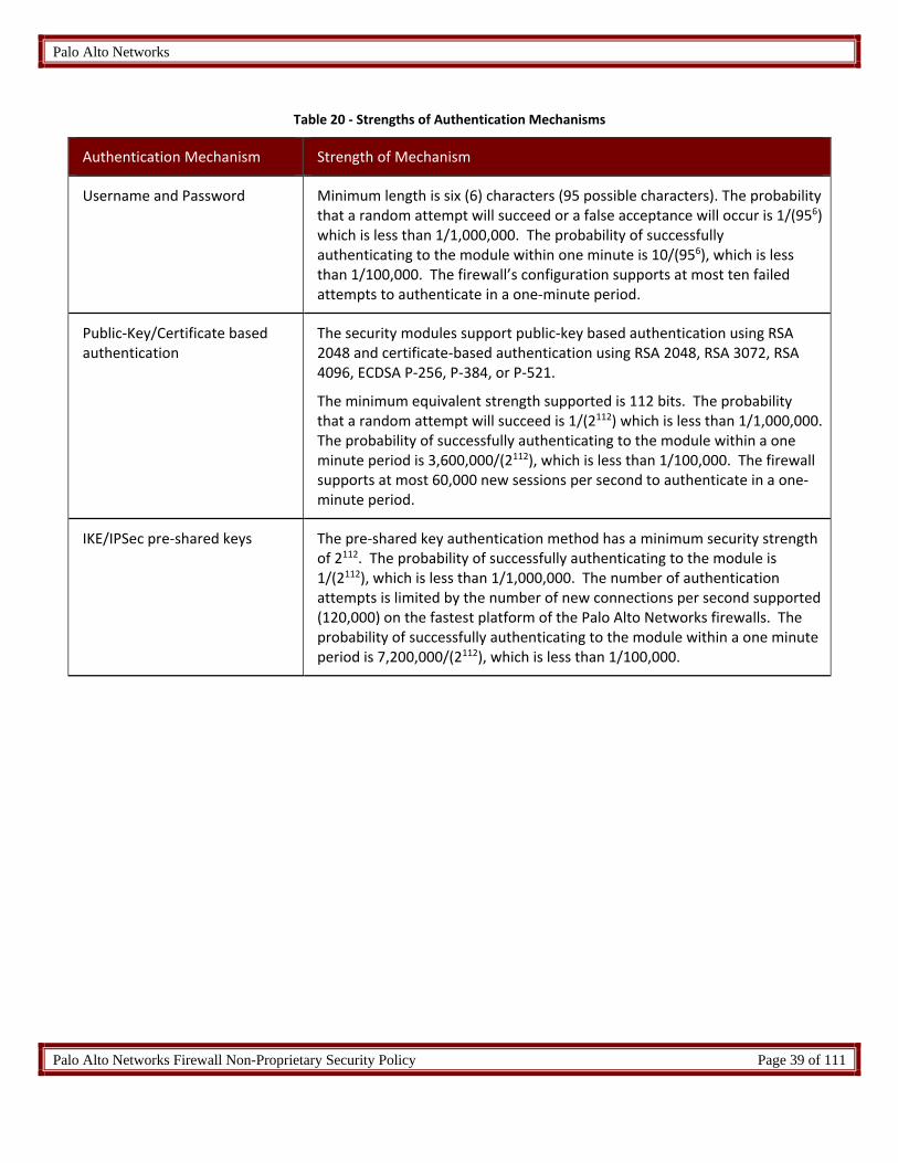
Table 20 ‐ Strengths of Authentication Mechanisms
Authentication Mechanism Strength of Mechanism
Username and Password Minimum length is six (6) characters (95 possible characters). The probability that a random attempt will succeed or a false acceptance will occur is 1/(956) which is less than 1/1,000,000. The probability of successfully authenticating to the module within one minute is 10/(956), which is less than 1/100,000. The firewall’s configuration supports at most ten failed attempts to authenticate in a one‐minute period.
Public‐Key/Certificate based authentication
The security modules support public‐key based authentication using RSA 2048 and certificate‐based authentication using RSA 2048, RSA 3072, RSA 4096, ECDSA P‐256, P‐384, or P‐521.
The minimum equivalent strength supported is 112 bits. The probability that a random attempt will succeed is 1/(2112) which is less than 1/1,000,000. The probability of successfully authenticating to the module within a one minute period is 3,600,000/(2112), which is less than 1/100,000. The firewall supports at most 60,000 new sessions per second to authenticate in a one‐minute period.
IKE/IPSec pre‐shared keys The pre‐shared key authentication method has a minimum security strength of 2112. The probability of successfully authenticating to the module is 1/(2112), which is less than 1/1,000,000. The number of authentication attempts is limited by the number of new connections per second supported (120,000) on the fastest platform of the Palo Alto Networks firewalls. The probability of successfully authenticating to the module within a one minute period is 7,200,000/(2112), which is less than 1/100,000.

Palo Alto Networks
Palo Alto Networks Firewall Non-Proprietary Security Policy Page 40 of 111
6 Access Control Policy
6.1 Roles and Services
The Approved and non‐Approved mode of operation provide identical services. While in the Approved mode of operation all CO and User services are accessed via SSH or TLS sessions. Approved and allowed algorithms, relevant CSPs, and public keys related to these protocols are accessed to support the following services. CSP access by services is further described in the following tables.
The services listed below are also available in the non‐Approved mode. In the Non‐Approved mode, SSH, TLS, and VPN processes will use non‐Approved Algorithms and Approved algorithms with non‐Approved strength.
Table 21 ‐ Authenticated Service Descriptions
Service Description
Security Configuration Management
Configuring and managing cryptographic parameters and setting/modifying security policy, creating User accounts and additional CO accounts, as well as configuring usage of third party external HSMs.
Other Configuration Networking parameter configuration, logging configuration, and other non‐security relevant configuration.
View Other Configuration
Read‐only of non‐security relevant configuration (see above).
Show Status View status via the web interface, command line interface or VPN session.
VPN Provide network access for remote users or site‐to‐site connections.
Firmware update Provides a method to update the firmware on the firewall.
Note: Additional information on the services the module provides can be found at https://www.paloaltonetworks.com/documentation.html
Table 22 ‐ Authenticated Services
Service Crypto Officer
User RA VPN S‐S VPN
Security Configuration Management Y Y(*) N N
Other Configuration Y N N N
View Other Configuration Y Y N N
Show Status Y Y Y Y

Palo Alto Networks
Palo Alto Networks Firewall Non-Proprietary Security Policy Page 41 of 111
Service Crypto Officer
User RA VPN S‐S VPN
VPN N N Y Y
Firmware update Y N N N
*Note: The User role has use of this service only to change their own password.
6.2 Unauthenticated Services
The cryptographic module supports the following unauthenticated services:
Table 23 ‐ Unauthenticated Services
Service Description
Zeroize The device will overwrite all CSPs.
Self‐Tests Run power up self‐tests on demand by power cycling the module.
Show Status (LEDs) View status of the module via the LEDs.
The zeroization procedure is invoked when the operator exits FIPS‐CC mode. The procedure consists of overwriting keystore files, formatting the harddisk, and overwriting with a reinstalled firmware image. The operator must be in control of the module during the entire procedure to ensure that it has successfully completed. During the zeroization procedure, no other services are available.
6.3 Definition of Critical Security Parameters (CSPs)
The modules contain the following CSPs:
Table 24 ‐ CSPs
CSP # CSP/Key Name Type Description
1 RSA Private Keys RSA RSA Private keys for generation of signatures, authentication or key establishment.
(RSA 2048, 3072, or 4096‐bit)
2 ECDSA Private Keys ECDSA ECDSA Private key for generation of signatures and authentication
(P‐256, P‐384, or P‐521)

Palo Alto Networks
Palo Alto Networks Firewall Non-Proprietary Security Policy Page 42 of 111
CSP # CSP/Key Name Type Description
3 TLS Pre‐Master Secret TLS Secret Secret value used to derive the TLS Master Secret along with client and server random nonces
4 TLS Master Secret TLS Secret Secret value used to derive the TLS session keys
5 TLS DH Private Components DH Diffie‐Hellman private FFC or EC component used in TLS
(DHE 2048, ECDHE P‐256, P‐384, P‐521)
6 TLS HMAC Keys HMAC TLS integrity and authentication session keys (SHA‐1, SHA‐256, SHA‐384)
7 TLS Encryption Keys AES TLS encryption session keys
(128 and 256 CBC or GCM)
8 SSH Session Authentication Keys
HMAC Authentication keys used in all SSH connections to the security module’s command line interface (HMAC‐SHA‐1, HMAC‐SHA2‐256, HMAC‐SHA2‐512)
9 SSH Session Encryption Keys AES Used in all SSH connections to the security module’s command line interface.
(128, 192, or 256 bits: CBC or CTR)
(128 or 256 bits: GCM)
10 SSH DH Private Components DH Diffie Hellman private component used in key establishment (DHE 2048, ECDHE P‐256, P‐384, P‐521)
11 S‐S VPN IPSec/IKE authentication Keys
HMAC (SHA‐1, SHA‐256, SHA‐384 or SHA‐512) Used to authenticate the peer in an IKE/IPSec tunnel connection.
12 S‐S VPN IPSec/IKE session Keys
AES Used to encrypt IKE/IPSec data. These are AES (128, 192, and 256 CBC) IKE keys and (128, 192, and 256 CBC, 128 CCM, 128 and 256 GCM) IPSec keys
13 S‐S VPN IPSec/IKE Diffie Hellman Private Components
DH Diffie‐Hellman private component used in key establishment
(DHE 2048, ECDHE P‐256, P‐384)

Palo Alto Networks
Palo Alto Networks Firewall Non-Proprietary Security Policy Page 43 of 111
CSP # CSP/Key Name Type Description
14 S‐S VPN IPSec Pre‐Shared Keys
Part of HMAC Entered into the module by the Crypto Officer once authenticated
15 RA VPN IPSec session Keys AES (128 CBC, 128/256‐GCM) Used to encrypt remote access sessions utilizing IPSec.
16 RA VPN IPSec authentication HMAC
HMAC (SHA‐1) Used in authentication of remote access IPSec data.
17 Password Password Authentication string with a minimum length of six (6) characters.
18 DRBG Seed and State DRBG DRBG seed coming from the NDRNG and AES 256 CTR DRBG state (V and Key) used in the generation of a random values
19 SNMPv3 Secrets SNMPv3 Secrets SNMPv3 Authentication Secret and Privacy Secret
20 SNMPv3 Keys SNMPv3 Keys AES‐128 Privacy key and HMAC‐SHA‐1 Authentication key
21 Protocol secrets Password Secret used by RADIUS or TACACS+ (minimum length of six (6) characters)
Note: The CSPs in Volatile memory locations are zeroized by overwrite with a pseudo random pattern followed by read‐verify. Intermediate plaintext key material (CSP) is zeroized when it is copied from one to another memory location. All keys (CSPs) are zeroized when they expire. Session keys (CSPs) are zeroized as soon as the associated session has ended/timed out/ or been closed. Private keys (CSPs) are zeroized when their corresponding public keys (certificates) expire.
6.4 Definition of Public Keys
The modules contain the following public keys:
Table 25 ‐ Public Keys
# Key Name Description
A. CA certificates RSA and/or ECDSA keys used to extend trust for certificates
B.
ECDSA public keys / certificates
ECDSA public keys managed as certificates for the verification of signatures, establishment of TLS, operator authentication and peer authentication.
(ECDSA P‐256, P‐384, or P‐521)

Palo Alto Networks
Palo Alto Networks Firewall Non-Proprietary Security Policy Page 44 of 111
# Key Name Description
C.
RSA public keys / certificates
RSA public keys managed as certificates for the verification of signatures, establishment of TLS, operator authentication and peer authentication.
(RSA 2048, 3072, or 4096‐bit)
D. TLS DH Public Components
Used in key agreement (DHE 2048, ECDHE P‐256, P‐384, P‐521)
E. SSH DH Public Components
Used in key agreement (DHE 2048, ECDHE P‐256, P‐384 and P‐521)
F. SSH Host Public Key SSH Host Public Key (RSA 2048, RSA 3072, RSA 4096, ECDSA P‐256, P‐384, or P‐521)
(The matching private key is among the RSA Private Keys or ECDSA Private Keys, in Table 21.)
G. SSH Client Public Key SSH Client RSA Public Key (RSA 2048, 3072, or 4096 bit)
H. S‐S VPN ‐ IPSec/IKE Diffie Hellman Public Component
Used in key agreement (DHE 2048, ECDHE P‐256, P‐384)
I. Public key for firmware content load test
Used to authenticate firmware and content to be installed on the firewall (RSA 2048)
J. Firmware integrity verification Key
Public key used to validate firmware integrity at power‐up (ECDSA P‐256)

Palo Alto Networks
Palo Alto Networks Firewall Non-Proprietary Security Policy Page 45 of 111
6.5 Definition of CSPs Modes of Access
Table 26 defines the relationship between access to CSPs and the different module services. The modes of access shown in the table are defined as:
R = Read: The module reads the CSP. The read access is performed when a CSP is is either exported from the module or executed by a security function.
W = Write: The module writes the CSP. The write access is typically performed after a CSP is imported into the module, or the module generates a CSP, or the module overwrites an existing CSP.
Z = Zeroize: The module zeroizes the CSP.
Table 26 ‐ CSP and Public Key Access Rights within Roles & Services
Role Authorized Service Mode Cryptographic Key or CSP (See Tables 24 & 25)
CO Security Configuration Management RW 1, 2, 3, 4, 5, 6, 7, 8, 9,10, 17, 18, 19, 20, 21, A, B, C, D, E, F, G, I
CO Other Configuration RW 1, 2, 3, 4, 5, 6, 7, 8, 9, 10, A, B, C, D, E, F, G
User, CO View Other Configuration RW 1, 2, 3, 4, 5, 6, 7, 8, 9, 10, 18, A, B, C, D, E, F, G (operator’s own password)
User Security Configuration Management RW 1, 2, 3, 4, 5, 6, 7, 8, 9, 10, 17, A, B, C, D, E, F, G(operator’s own password)
User, CO Show Status R 1, 2, 3, 4, 5, 6, 7, 8, 9, 10, A, B, C, D, E, F, G
S‐S VPN VPN R 11, 12, 13, 14, B, C, H
RA VPN VPN R 1, 2, 3, 4, 5, 6, 7, 15, 16, 18, A, B, C, D
CO Firmware Update RW 1, 2, 3, 4, 5, 6, 7, 8, 9, 10, 17, A, B, C, D, E, F, G
Unauthenticated Self‐Tests R J
Unauthenticated Show Status (LEDs) N/A N/A
Unauthenticated Zeroize Z All CSPs and public keys are zeroized.

Palo Alto Networks
Palo Alto Networks Firewall Non-Proprietary Security Policy Page 46 of 111
7 Operational Environment
The FIPS 140‐2 Area 6 Operational Environment requirements are not applicable because the Firewalls do not contain modifiable operational environments. The operational environment is limited since the modules include a firmware load service to support necessary updates. New firmware versions within the scope of this validation must be validated through the FIPS 140‐2 CMVP. Any other firmware loaded into these modules is out of the scope of this validation and requires a separate FIPS 140‐2 validation.
8 Security Rules
The module design corresponds to the module security rules. This section documents the security rules enforced by the cryptographic module to implement the security requirements of this FIPS 140‐2 Level 2 module.
8.1 FIPS 140‐2 Security Rules
1. The cryptographic module provides four distinct operator roles. These are the User role,
Remote Access VPN role, Site‐to‐site VPN role, and the Cryptographic Officer role.
2. The cryptographic module provides identity‐based authentication.
3. The cryptographic module clears previous authentications on power cycle.
4. When the module has not been placed in a valid role, the operator does not have access
to any cryptographic services.
5. The cryptographic module performs the following tests
A. Power up Self‐Tests
1. Cryptographic algorithm tests
a. AES Encrypt Known Answer Test
b. AES Decrypt Known Answer Test
c. AES CMAC Known Answer Test
d. AES GCM Encrypt Known Answer Test
e. AES GCM Decrypt Known Answer Test
f. AES CCM Encrypt Known Answer Test
g. AES CCM Decrypt Known Answer Test
h. RSA Sign Known Answer Test
i. RSA Verify Known Answer Test
j. RSA Encrypt Known Answer Test
k. RSA Decrypt Known Answer Test
l. ECDSA Sign Known Answer Test
m. ECDSA Verify Known Answer Test
n. HMAC‐SHA‐1 Known Answer Test
o. HMAC‐SHA‐256 Known Answer Test

Palo Alto Networks
Palo Alto Networks Firewall Non-Proprietary Security Policy Page 47 of 111
p. HMAC‐SHA‐384 Known Answer Test
q. HMAC‐SHA‐512 Known Answer Test
r. SHA‐1 Known Answer Test
s. SHA‐256 Known Answer Test
t. SHA‐384 Known Answer Test
u. SHA‐512 Known Answer Test
v. DRBG SP800‐90A Known Answer Tests
w. SP 800‐90A Section 11.3 Health Tests
x. DH Known Answer Test
y. ECDH Known Answer Test
2. Firmware Integrity Test –verified with HMAC‐SHA‐256 and ECDSA P‐256.
B. Critical Functions Tests
1. N/A
C. Conditional Self‐Tests
1. Continuous Random Number Generator (RNG) test – performed on
NDRNG and DRBG
2. RSA Pairwise Consistency Test
3. ECDSA Pairwise Consistency Test
4. Firmware Load Test – Verify RSA 2048 with SHA‐256 signature on
firmware at time of load
5. If any conditional test fails, the module will output a description of the
error condition.
6. The operator can command the module to perform the power‐up self‐test by cycling
power of the module.
7. Power‐up self‐tests do not require any operator action.
8. Data output is inhibited during power‐up self‐tests, zeroization and error states.
9. Status information does not contain CSPs or sensitive data that if misused could lead to
a compromise of the module.
10. There are no restrictions on which keys or CSPs are zeroized by the zeroization service.
11. The module maintains separation between concurrent operators.
12. The module does not support a maintenance interface or role.
13. The module does not have any external input/output devices used for entry/output of
data.
14. The module does not enter or output plaintext CSPs.
15. The module does not output intermediate key generation values.
Vendor imposed security rules:

Palo Alto Networks
Palo Alto Networks Firewall Non-Proprietary Security Policy Page 48 of 111
1. If the cryptographic module remains inactive in any valid role for the administrator specified
time interval, the module automatically logs out the operator.
2. The module enforces a timed access protection mechanism that supports at most ten
authentication attempts per minute. After the administrator specified number of consecutive
unsuccessful password validation attempts have occurred, the cryptographic module shall
enforce a wait period of at least one (1) minute before any more login attempts can be
attempted. This wait period shall be enforced even if the module power is momentarily
removed.
3. In FIPS‐CC mode, the following rules shall apply:
a. The operator should not enable TLSv1.0; it is disabled by default.
Note that TLSv1.0 can be used in an Approved mode of operation (Approved TLS KDF
algorithm); however, TLSv1.0 protocol is no longer considered as secure because of
the Cipher Block Chaining IV attack.
b. Pre‐shared keys used for IKE/IPsec must be at least 14 bytes in length.
c. If using RADIUS, it must be configured using TLS. In all other cases, the module shall
be configured in non‐Approved mode of operation.
d. If using TACACS+, configure the service route via an IPSec tunnel, and ensure the
TACACS+ server is configured for a minimum password length of six (6) characters (to
match Table 17 of this document), or greater. In all other cases, the module shall be
configured in non‐Approved mode of operation.
e. The operator shall not generate 4096‐bit RSA key in FIPS‐CC mode. If the operator
wants to generate 4096‐bit RSA key, the module shall be configured in non‐Approved
mode of operation.

Palo Alto Networks
Palo Alto Networks Firewall Non-Proprietary Security Policy Page 49 of 111
8.2 Physical Security Mechanisms
The multi‐chip standalone modules are production quality containing standard passivation. Chip components are protected by an opaque enclosure. There are tamper evident seals that are applied on the modules by the Crypto‐Officer. All unused seals are to be controlled by the Crypto‐Officer. The seals prevent removal of the opaque enclosure without evidence. The Crypto‐Officer must ensure that the module surface is clean and dry. Tamper‐evident seals must be pressed firmly onto the adhering surfaces during installation and once applied the Crypto‐ Officer shall permit 24 hours of cure time for all tamper‐evident seals. The Crypto‐Officer should inspect the seals and shields for evidence of tamper every 30 days. If the seals show evidence of tamper, the Crypto‐Officer should assume that the modules have been compromised and contact Customer Support.
Note: For ordering information, see Table 2 for FIPS kit part numbers and versions. Opacity shields and Tamper Seals are included in the FIPS kits.
Refer to Appendix A for instructions on installation of the tamper seals and opacity shields. The locations of the five (5) tamper‐evident seals implemented on the PA‐200 are shown in Figure 27 through Figure 28
Figure 27 ‐ PA‐200 Left Side and Top Tamper Seal Placement (3)
Figure 28 ‐ PA‐200 Right Side Tamper Seal Placement (2)
[1]
[2]
[3]
[4]
[5]

Palo Alto Networks
Palo Alto Networks Firewall Non-Proprietary Security Policy Page 50 of 111
Refer to Appendix B for instructions on installation of the tamper seals and opacity shields. The locations of the six (6) tamper‐evident seals implemented on the PA‐220 are shown in Figure 29 through Figure 30.
Figure 29 ‐ PA‐220 Front with enclosure
Figure 30 – PA‐220 Right Side and Front Tamper Seal Placement (3)
Figure 31 – PA‐220 Left Side and Front Tamper Seal Placement (3)
Refer to Appendix L for instructions on installation of five (5) tamper seals and opacity shields for the PA‐220R.
[1]
[2]
[3]
[4]
[5]
[6]

Palo Alto Networks
Palo Alto Networks Firewall Non-Proprietary Security Policy Page 51 of 111
Refer to Appendix C for instructions on installation of the tamper seals and opacity shields. The locations of the twelve (12) tamper‐evident seals implemented on the PA‐500 (and PA‐500‐2GB) are shown in Figure 31 through Figure 35.
Figure 32 ‐ PA‐500 with Front Opacity Shield
Figure 33 ‐ PA‐500 Front Top Tamper Seal Placement (1)
Figure 34 ‐ PA‐500 Left Side Tamper Seal Placement (3)
[1]
[4] [3]
[2]

Palo Alto Networks
Palo Alto Networks Firewall Non-Proprietary Security Policy Page 52 of 111
Figure 35 ‐ PA‐500 Right Side Tamper Seal Placement (2)
Figure 36 ‐ PA‐500 Rear Tamper Seal Placement (6)
[5]
[6]
[7]
[10]
[11]
[12]
[9]
[8]

Palo Alto Networks
Palo Alto Networks Firewall Non-Proprietary Security Policy Page 53 of 111
Refer to Appendix D for instructions on installation of the eleven (11) tamper seals and opacity shields for the PA‐800 Series.

Palo Alto Networks
Palo Alto Networks Firewall Non-Proprietary Security Policy Page 54 of 111
Refer to Appendix E for instructions on installation of the tamper seals and opacity shields for the PA‐3020 and PA‐3050. The locations of the seven (7) tamper‐evident seals on the PA‐3020/PA‐3050 modules are shown in Figure 37 through Figure 40.
Figure 37 ‐ PA‐3020 / PA‐3050 side with Opacity Shield
Figure 38 ‐ PA‐3020/PA‐3050 Series Tamper Seal Placement (3)
[1]
[2]
[3]

Palo Alto Networks
Palo Alto Networks Firewall Non-Proprietary Security Policy Page 55 of 111
Figure 39 ‐ PA‐3020/PA‐3050 Series Tamper Seal Placement (2)
Figure 40 ‐ PA‐3020/PA‐3050 Series Tamper Seal Placement (2)
Refer to Appendix F for instructions on installation of the tamper seals and opacity shields for the PA‐3060. The locations of the eight (8) tamper‐evident seals implemented on the PA‐3060 module are shown in Figure 41 through Figure 44.
Figure 41 – PA‐3060 Right side
Figure 42 – PA‐3060 Left side
[4] [5]
[6] [7]
[1] [2] [3]
[4] [6] [5]

Palo Alto Networks
Palo Alto Networks Firewall Non-Proprietary Security Policy Page 56 of 111
Refer to Appendix H for instructions on installation of the tamper seals and opacity shields for the PA‐5000 series. The locations of the seventeen (17) tamper‐evident seals implemented on the PA‐5000 Series modules are shown in Figure 45 through Figure 47.
Figure 45 ‐ PA‐5000 Series Rear Tamper Seal Placement (9) with opacity shields
Figure 43 – PA‐3060 Front/Top Tamper Seal Placement
Figure 44 – PA‐3060 Front/Bottom Tamper Seal Placement
Refer to Appendix G for instructions on installation of the nineteen (19) tamper seals and opacity shields for the PA‐3200 Series.
[8]
[1]
[9]
[3] [5]
[2] [4] [6]
[7]
[7]
[8]
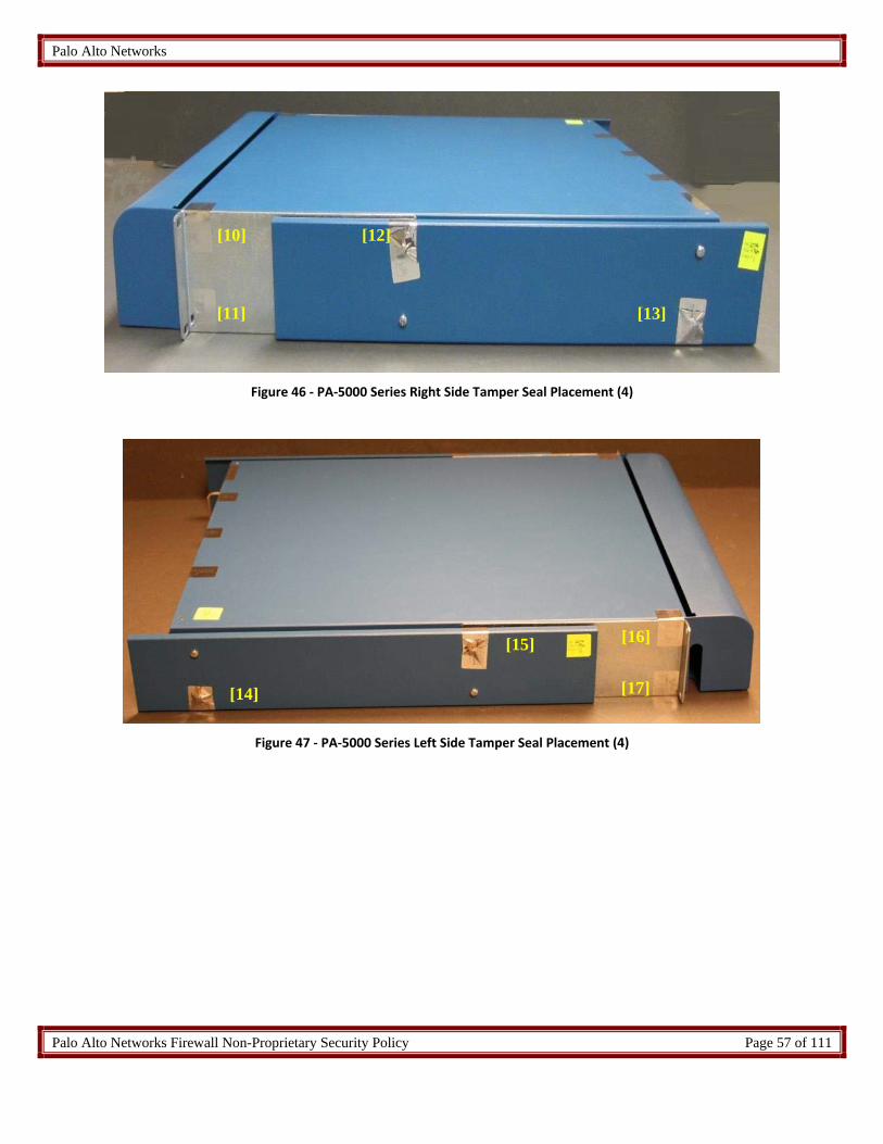
Palo Alto Networks
Palo Alto Networks Firewall Non-Proprietary Security Policy Page 57 of 111
Figure 46 ‐ PA‐5000 Series Right Side Tamper Seal Placement (4)
Figure 47 ‐ PA‐5000 Series Left Side Tamper Seal Placement (4)
[10]
[11]
[12]
[13]
[15]
[14] [17]
[16]

Palo Alto Networks
Palo Alto Networks Firewall Non-Proprietary Security Policy Page 58 of 111
Refer to Appendix I for instructions on installation of the tamper seals and opacity shields for the PA‐5200 series. The locations of the twenty‐eight (28) tamper‐evident seals implemented on the PA‐5200 Series modules are shown in Figure 48 through Figure 51
Figure 48 ‐ PA‐5200 Series front Opacity Shield
Figure 49 ‐ PA‐5200 Series Left Side with Front Opacity Shield
[1]
[2] [3]
[4]
[5]
[6] [7]
[8] [9]
[12]
[10]
[13]
[11] [15] [14]
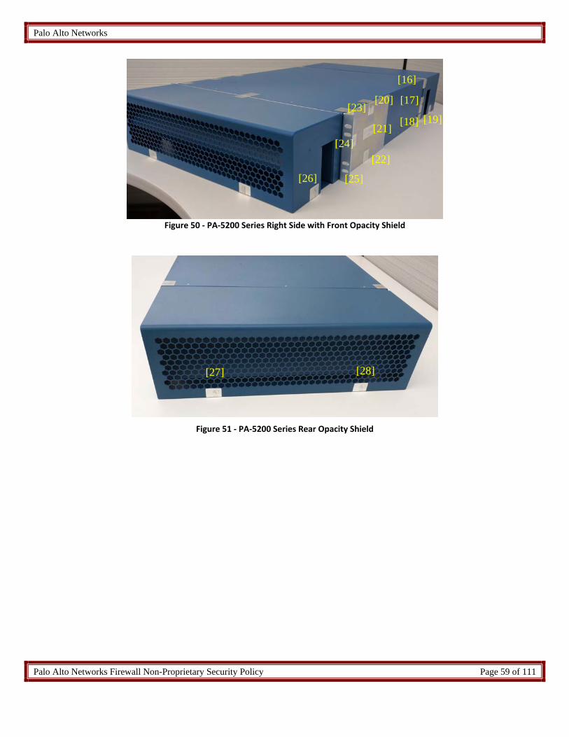
Palo Alto Networks
Palo Alto Networks Firewall Non-Proprietary Security Policy Page 59 of 111
Figure 50 ‐ PA‐5200 Series Right Side with Front Opacity Shield
Figure 51 ‐ PA‐5200 Series Rear Opacity Shield
[16]
[17]
[18] [19]
[20] [23]
[21] [24]
[22]
[25] [26]
[27] [28]

Palo Alto Networks
Palo Alto Networks Firewall Non-Proprietary Security Policy Page 60 of 111
Refer to Appendix J for instructions on installation of the tamper seals and opacity shields for the PA‐7050. The locations of the twenty‐four (24) tamper‐evident seals implemented on the PA‐7050 Series modules are shown in Figure 52 through Figure 60.
Figure 52 ‐ PA‐7050 Front View with Opacity Shields Figure 53 ‐ PA‐7050 Rear View with Opacity Shields
Figure 54 ‐ PA‐7050 Front and Right Side with Opacity Shields
Figure 55 ‐ PA‐7050 Rear and Left Side with Opacity Shields

Palo Alto Networks
Palo Alto Networks Firewall Non-Proprietary Security Policy Page 61 of 111
Front
Rear
Figure 56 ‐ PA‐7050 Tamper Seal Placement for Top Plenum (1‐4)
Front Rear
Figure 57 ‐ PA‐7050 Tamper Seal Placement for Bottom Plenum (5‐6)
[1] [3]
[4]
[2]
[5] [6]

Palo Alto Networks
Palo Alto Networks Firewall Non-Proprietary Security Policy Page 62 of 111
Figure 58 ‐ PA‐7050 Tamper Seal Placement for Rear (7‐20)
Figure 59 ‐ PA‐7050 Tamper Seal Placement for Top Plenum Bracket (21‐22)
[7] [8] [9]
[10] [11] [12]
[13]
[14]
[15]
[16]
[17] [18]
[19]
[20]
[21] [22]

Palo Alto Networks
Palo Alto Networks Firewall Non-Proprietary Security Policy Page 63 of 111
Figure 61 ‐ PA‐7080 Front with Opacity Shield
Figure 62 ‐ PA‐7080 Rear
Figure 60 ‐ PA‐7050 Tamper Seal Placement for Bottom Plenum Bracket (23‐24)
Refer to Appendix K for instructions on installation of the tamper seals and opacity shields for the PA‐7080. The locations of the ten (10) tamper‐evident seals implemented on the PA‐7080 Series modules are shown in Figure 61 through Figure 64
[1]
[23] [24]
[2]
[3] [4]
[5] [6]
[7] [8]

Palo Alto Networks
Palo Alto Networks Firewall Non-Proprietary Security Policy Page 64 of 111
Figure 63 ‐ PA‐7080 Tamper Seal Placement on Left Side for Front Opacity Shield (1)
Figure 64 ‐ PA‐7080 Tamper Seal Placement on Right Side for Front Opacity Shield (1)
8.3 Operator Required Actions
Table 27 ‐ Inspection/Testing of Physical Security Mechanisms
Model Physical Security Mechanisms
Recommended Frequency of Inspection/Test
Inspection/Test Guidance Details
PA‐7080, PA‐7050, PA‐5220, PA‐5250, PA‐5260, PA‐5280, PA‐5060, PA‐5050, PA‐5020, PA‐3220, PA‐3250, PA‐3260, PA‐3060, PA‐3050, PA‐3020, PA‐820, PA‐850 PA‐500, PA‐500‐2GB, PA‐220R, PA‐220, PA‐200
Tamper‐Evident Seals
30 days Verify integrity of tamper‐evident seals in the locations identified in the FIPS Kit Installation Guide. Seal integrity to be verified within the modules operating temperature range.
PA‐7050 Top, Bottom, Front and Rear Opacity Shields
30 days Verify that the plenums and opacity shields have not been deformed from their original shape, thereby reducing their effectiveness
[9]
[10]

Palo Alto Networks
Palo Alto Networks Firewall Non-Proprietary Security Policy Page 65 of 111
Model Physical Security Mechanisms
Recommended Frequency of Inspection/Test
Inspection/Test Guidance Details
PA‐5060, PA‐5050, PA‐5020, PA‐3050, PA‐3020, PA‐500
Front Cover and Side Opacity Shields
30 days Verify that front cover and side opacity shields have not been deformed from their original shape, thereby reducing their effectiveness
PA‐3060, PA‐3220, PA‐3250, PA‐3260
Front and Rear Covers
30 days Verify that front and rear covers have not been deformed from their original shape, thereby reducing their effectiveness
PA‐7080 Front Cover 30 days Verify that front cover has not been deformed from its original shape thereby reducing its effectiveness
PA‐220, PA‐200 Front cover and Cage Enclosure
30 days Verify that front cover and cage enclosure have not been deformed from their original shape, thereby reducing their effectiveness
9 Mitigation of Other Attacks Policy
The module has not been designed to mitigate any specific attacks outside of the scope of FIPS 140‐2, so these requirements are not applicable.
10 Definitions and Acronyms
API – Application Programming Interface
App‐ID – Application Identification ‐ Palo Alto Networks’ ability to identify applications and apply security policy based on the ID rather than the typical port and protocol‐based classification.
BGP – Border Gateway protocol – Dynamic routing protocol
CA – Certificate authority
Content‐ID – Content Identification – Palo Alto Networks’ threat prevention features including Antivirus, Antispyware, and Intrusion Prevention.
CO – Cryptographic Officer
DLP – Data loss prevention
Gbps – Gigabits per second

Palo Alto Networks
Palo Alto Networks Firewall Non-Proprietary Security Policy Page 66 of 111
HA – High Availability
HSCI ‐ High Speed Chassis Interconnect
IKE – Internet Key Exchange
IP – Internet Protocol
IPSec – Internet Protocol Security
LDAP – Lightweight Directory Access Protocol
LED – Light Emitting Diode
NDRNG – Non‐deterministic random number generator
OCSP – Online Certificate Status Protocol
OSPF – Open Shortest Path First – Dynamic routing protocol
PAN‐OS – Palo Alto Networks’ Operating System
QoS – Quality of Service
QSFP ‐ Quad Small Form‐factor Pluggable
RA VPN – Remote Access Virtual Private Network
RIP – Routing Information Protocol – Dynamic routing protocol
RJ45 – Networking Connector
RNG –Random number generator
S‐S VPN – Site to site Virtual Private Network
SFP – Small Form‐factor Pluggable Transceiver
SSL – Secure Sockets Layer
TLS – Transport Layer Security
USB – Universal Serial Bus
User‐ID – User Identification – Palo Alto Networks’ ability to apply security policy based on who initiates the traffic rather than the typical IP‐based approach.
VPN – Virtual Private Network
XML – Extensible Markup Language
11 Reference Documents
FIPS 140‐2 ‐ FIPS Publication 140‐2 Security Requirements for Cryptographic Modules

Palo Alto Networks
Palo Alto Networks Firewall Non-Proprietary Security Policy Page 67 of 111
12 Appendix A ‐ PA‐200 ‐ FIPS Accessories/Tamper Seal Installation (5 Seals)
1. Insert the PA‐200 unit into the cage.
2. Secure right side of the PA‐200 unit to the cage with (2x) 4‐40x1/2” screws provided in the kit. Repeat for the left side of the cage.

Palo Alto Networks
Palo Alto Networks Firewall Non-Proprietary Security Policy Page 68 of 111
3. Install the front panel with the curve side up to the front cage.
4. Secure the front panel to the cage with (5x) 4‐40x3/16” screws.

Palo Alto Networks
Palo Alto Networks Firewall Non-Proprietary Security Policy Page 69 of 111
5. Affix a tamper seal on the top middle of the front panel screw.
6. Affix two (2) tamper seals over both screw mounting holes on the cage and right side screw on the front panel. Repeat for the left side

Palo Alto Networks
Palo Alto Networks Firewall Non-Proprietary Security Policy Page 70 of 111
13 Appendix B ‐ PA‐220 ‐ FIPS Accessories/Tamper Seal Installation (6 Seals) 1. Place the firewall upside down on a flat Electrostatic Discharge (ESD) protected surface and
ground yourself by touching a metal surface on the firewall.
2. Slide the firewall in to the FIPS chassis cover and attach it to the cover using a Phillips‐head
screwdriver to tighten four (4) captive screws (two (2) screws on each side of the cover).
3. Install the front (network, management, and console) cables (you cannot access the front ports
after you complete the front‐cover install described in the following steps).
4. Place the FIPS front cover onto the FIPS chassis cover and attach it using four (4) #4‐40 x .25”
screws (two (2) screws on each side of the cover).

Palo Alto Networks
Palo Alto Networks Firewall Non-Proprietary Security Policy Page 71 of 111
5. Route the front‐port cables through the front‐cover cable‐guide openings.
6. Attach the FIPS front‐cover panel to the FIPS front cover by sliding the two (2) panel tabs under
the FIPS chassis cover and then attach the panel using two (2) #4‐40 x .25” screws.
7. Apply a tamper‐evident seal to each location shown in the following illustration (six (6) seals
total). After all seals are applied, place the firewall right‐side up.

Palo Alto Networks
Palo Alto Networks Firewall Non-Proprietary Security Policy Page 72 of 111
14 Appendix C ‐ PA‐500 ‐ FIPS Accessories/Tamper Seal Installation (12 Seals)
1. Remove the right side cover screws. Repeat for the left side cover screws.
2. Install the right side FIPS opacity shield and secure with two (2) #4‐40x1/4” SEMS screws provided in the kit. Repeat for the left side.
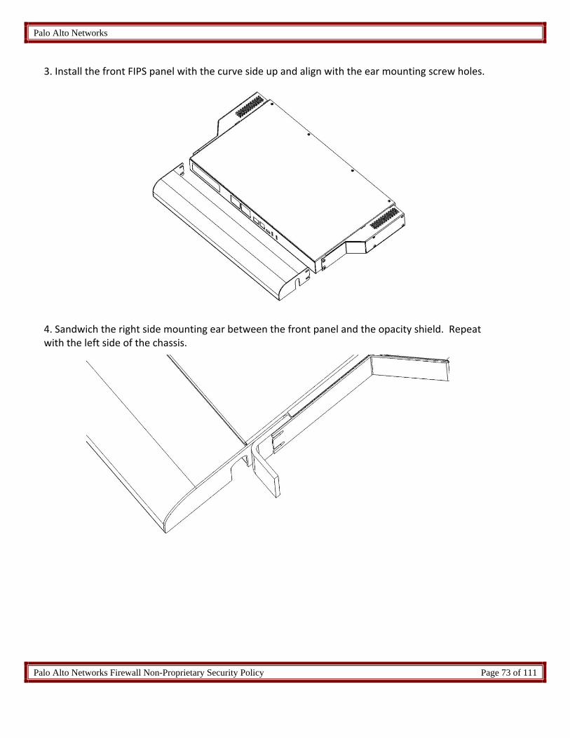
Palo Alto Networks
Palo Alto Networks Firewall Non-Proprietary Security Policy Page 73 of 111
3. Install the front FIPS panel with the curve side up and align with the ear mounting screw holes.
4. Sandwich the right side mounting ear between the front panel and the opacity shield. Repeat with the left side of the chassis.

Palo Alto Networks
Palo Alto Networks Firewall Non-Proprietary Security Policy Page 74 of 111
5. Install and secure the right side mounting ear with two (2) #6‐32x1/2” Truss screws provided in the kit. Repeat on the left side.
6. Remove one (1) upper‐right fan screw.

Palo Alto Networks
Palo Alto Networks Firewall Non-Proprietary Security Policy Page 75 of 111
7. Install and partially tighten the screw on one of the fan guard mounting holes.
8. Remove the other three (3) fan screws.
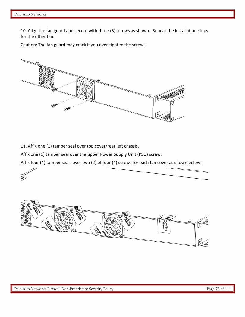
Palo Alto Networks
Palo Alto Networks Firewall Non-Proprietary Security Policy Page 76 of 111
10. Align the fan guard and secure with three (3) screws as shown. Repeat the installation steps for the other fan.
Caution: The fan guard may crack if you over‐tighten the screws.
11. Affix one (1) tamper seal over top cover/rear left chassis.
Affix one (1) tamper seal over the upper Power Supply Unit (PSU) screw.
Affix four (4) tamper seals over two (2) of four (4) screws for each fan cover as shown below.

Palo Alto Networks
Palo Alto Networks Firewall Non-Proprietary Security Policy Page 77 of 111
12 Affix a tamper seal over both screw access holes on the left side opacity shield.
Affix a tamper seal over the bottom ear screw on the left side of the chassis.
Affix a tamper seal on top of the opacity shield/cover on the left side of the chassis.
13. Affix a tamper seal over the bottom ear screw on the right side of the chassis.
Affix a tamper seal on top of the opacity shield/cover on the right side of the chassis.
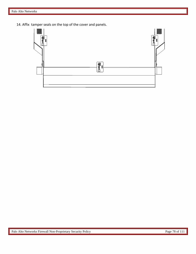
Palo Alto Networks
Palo Alto Networks Firewall Non-Proprietary Security Policy Page 78 of 111
14. Affix tamper seals on the top of the cover and panels.

Palo Alto Networks
Palo Alto Networks Firewall Non-Proprietary Security Policy Page 79 of 111
15 Appendix D ‐ PA‐800 series ‐ FIPS Accessories/Tamper Seal Installation (11 Seals)
1. Place the firewall on a flat Electrostatic Discharge (ESD) protected surface and ground yourself by
touching a metal surface on the firewall.
2. Place the FIPS back cover onto the back of the firewall and attach it using four #4‐40 x 5/16 screws (two screws
on each side of the back cover).
3. Insert the front (network, management, and console) cables in to the front ports.
4. Place the FIPS front cover onto the front of the firewall and place the rack‐mount brackets over the holes on
the front cover. Attach the front cover and rack‐mount brackets to the firewall using eight (8) #6‐32 x 5/16”
rack‐mount bracket screws (shipped with the firewall)—use four (4) screws on each side. Route the front
cables through the front‐cover cable‐guide opening.
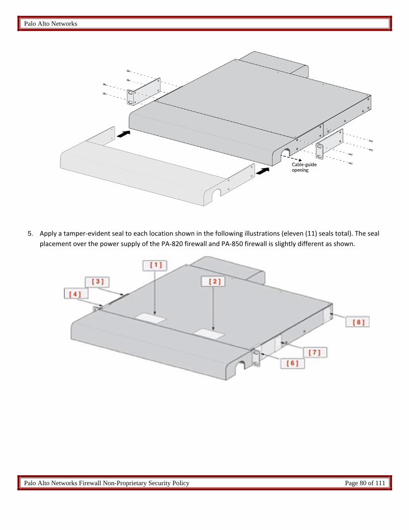
Palo Alto Networks
Palo Alto Networks Firewall Non-Proprietary Security Policy Page 80 of 111
5. Apply a tamper‐evident seal to each location shown in the following illustrations (eleven (11) seals total). The seal
placement over the power supply of the PA‐820 firewall and PA‐850 firewall is slightly different as shown.

Palo Alto Networks
Palo Alto Networks Firewall Non-Proprietary Security Policy Page 81 of 111

Palo Alto Networks
Palo Alto Networks Firewall Non-Proprietary Security Policy Page 82 of 111
16 Appendix E ‐ PA‐3020 and PA‐3050 ‐ FIPS Accessories/Tamper Seal Installation (7 Seals)
1. Install the front panel with the curve side up and line it up to the left and right side ear
mounting holes.
2. Install and secure the right side mounting ear and two (2) #6‐32x1/2” screws provided in the
kit. Repeat the same step on the left side of the chassis.

Palo Alto Networks
Palo Alto Networks Firewall Non-Proprietary Security Policy Page 83 of 111
3. Install the right side FIPS plenum and secure with four (4) #6‐32x1” SEM screws provided by
the kit. Repeat the same steps for the left side.
4. Affix a tamper seal to cover the right side bottom ear mounting bracket screw. Repeat the
same steps for the left side.
Affix a tamper seal at right side of the chassis between the top cover and the FIPS plenum.
Affix another tamper seal between the bottom of the chassis and the FIPS plenum. Repeat
the same steps for the left side.

Palo Alto Networks
Palo Alto Networks Firewall Non-Proprietary Security Policy Page 84 of 111
5. Affix a tamper seal on top of the cover / panel.

Palo Alto Networks
Palo Alto Networks Firewall Non-Proprietary Security Policy Page 85 of 111
17 Appendix F ‐ PA‐3060 ‐ FIPS Accessories/Tamper Seal Installation (8 Seals) 1. From the front of the PA‐3060, attach the Left and Right Front Cover brackets using the screws
provided.
2. Attach Front cover to the front of the PA‐3060 using the brackets and the supplied bolts and nuts.
Ensure the gap in the cover is positioned below the networking interfaces.

Palo Alto Networks
Palo Alto Networks Firewall Non-Proprietary Security Policy Page 86 of 111
3. Attach Rear Cover to the rear of the PA‐3060. Ensure the gap in the cover is positioned below the
power supplies.
4. Affix tamper evident seals as follows.
A. Attach a tamper seal to the top of the module overlapping the front opacity shield and
the PA‐3060.
B. Attach three (3) seals to the right side of the PA‐3060 covering each screw used to attach
the front bracket and rear opacity cover.
C. Attach three (3) seals to the left side of the PA‐3060 covering each screw used to attach
the front bracket and rear opacity cover.

Palo Alto Networks
Palo Alto Networks Firewall Non-Proprietary Security Policy Page 87 of 111
5. Viewing the bottom of the PA‐3060.
D. Attach a tamper seal overlapping the front opacity shield and the PA‐3060.

Palo Alto Networks
Palo Alto Networks Firewall Non-Proprietary Security Policy Page 88 of 111
18 Appendix G – PA‐3200 Series – FIPS Accessories/Tamper Seal Installation (19 Seals)
1. Install the back cover to the back of the firewall
2. Attach the bracket to the firewall that will be used. Note: The firewall can use a mid‐mount, front‐
mount or four‐post mount. All seal placement is the same for the various use cases.

Palo Alto Networks
Palo Alto Networks Firewall Non-Proprietary Security Policy Page 89 of 111
3. Place 19 tamper seals on the module. Note: Tamper seal placement is the same for all mount types. Seal #16 is
required only for the front‐mount of four‐post rack installations. It is not required for the mid‐mount
installation

Palo Alto Networks
Palo Alto Networks Firewall Non-Proprietary Security Policy Page 90 of 111
19 Appendix H ‐ PA‐5000 Series ‐ FIPS Accessories/Tamper Seal Installation (17 Seals)
1. Install the front panel.
2. Install the right FIPS mounting bracket and secure with two (2) #8‐32x3/8” screws provided in the original
accessory kit. Repeat for the left mounting bracket.
3. Install the side panel on the right side of the chassis and secure with four (4) #8‐32x1.00”L screws. Place the
leading edge towards front of the chassis. Repeat for the left side of the chassis.
Leading Edge

Palo Alto Networks
Palo Alto Networks Firewall Non-Proprietary Security Policy Page 91 of 111
4. Affix two (2) tamper‐evident seals over both upper and lower screws on the FIPS mounting bracket. Repeat
for the left side panel.
5. Affix two (2) tamper evident seals over front upper and rear lower of the right side panel screws. Repeat for
the left side panel.
6. Affix three (3) tamper‐evident seals on the top cover /rear chassis. Ensure the top cover screws are covered
by the seals.

Palo Alto Networks
Palo Alto Networks Firewall Non-Proprietary Security Policy Page 92 of 111
7. Affix a tamper‐evident seal on the top cover/fan access panel.
Affix another tamper‐evident seal on the bottom chassis/fan access panel.
8. Affix a tamper‐evident seal on upper HDD access panel/rear chassis.
Affix a tamper‐evident seal on lower HDD access panel/rear chassis.
9. Affix a tamper‐evident seal on the upper left PSU/rear chassis.
Affix a tamper‐evident seal on the upper right PSU/rear chassis.

Palo Alto Networks
Palo Alto Networks Firewall Non-Proprietary Security Policy Page 93 of 111
20 Appendix I ‐ PA‐5200‐ FIPS Accessories/Tamper Seal Installation (28 Seals) 1. Place the firewall upside down on a flat Electrostatic Discharge (ESD) protected surface and ground
yourself by touching a metal surface on the firewall.
2. Install power cables: plug the power cords in to the power inlets located on the back of the firewall and connect
the ground lug and ground cable to the ground lug bolts (you cannot access these back ports after you attach the
FIPS back cover).
3. Place the FIPS back cover onto the back of the firewall and attach it to the firewall using four (4) #8‐32 x
1/4” screws (two (2) screws on each side of the cover). Route the power cables through the back‐cover
cable‐guide openings.
4. Attach the FIPS back‐cover panel to the FIPS back cover using four (4) #4‐40 x 1/4” screws (one (1) screw
on each side of the cover and two (2) screws on the back of the cover).

Palo Alto Networks
Palo Alto Networks Firewall Non-Proprietary Security Policy Page 94 of 111
5. Place the FIPS front cover onto the front of the firewall and place the rack‐mount brackets over the holes
on the front cover. Attach the front cover and rack‐mount brackets to the firewall using eighteen (18) #8‐
32 x 5/16” screws (shipped with the firewall)—use nine (9) screws on each side.
6. Apply a tamper‐evident seal to each location shown in the illustrations (28 seals).

Palo Alto Networks
Palo Alto Networks Firewall Non-Proprietary Security Policy Page 95 of 111

Palo Alto Networks
Palo Alto Networks Firewall Non-Proprietary Security Policy Page 96 of 111
21 Appendix J ‐ PA‐7050 ‐ FIPS Accessories/Tamper Seal Installation (24 Seals) 1. Attach front right rack mount brackets in 4‐post rack position. Do not attach rear rack mount
brackets. Note that brackets are rotated 180 degrees, so the screw holes lineup and the rack mount
holes are now on the front of the chassis.
2. Align right plenum bracket with five (5) open screw holes. Attach air plenum brackets using five (5) of
the remaining bracket screws as shown. Repeat for left side.

Palo Alto Networks
Palo Alto Networks Firewall Non-Proprietary Security Policy Page 97 of 111
3. Attach bottom plenum to the front right rack mount bracket. Place only the middle two (2) screws.
4. Attach the bottom plenum to the rearward right plenum bracket.

Palo Alto Networks
Palo Alto Networks Firewall Non-Proprietary Security Policy Page 98 of 111
5. Rotate PA‐7050 chassis clockwise 90 degrees onto the bottom plenum.
6. Assemble top plenum and cable guide hardware.

Palo Alto Networks
Palo Alto Networks Firewall Non-Proprietary Security Policy Page 99 of 111
7. Attach top plenum to the front left rack mount bracket
8. Attach front opacity shield using the four (4) captive screws

Palo Alto Networks
Palo Alto Networks Firewall Non-Proprietary Security Policy Page 100 of 111
9. Attach top plenum to the rearward left plenum bracket along with plenum’s rear opacity shield as
shown
10. Loosen four (4) screws on the panel containing the power supply vent. Insert the power supply vent
opacity shield and tighten screws.

Palo Alto Networks
Palo Alto Networks Firewall Non-Proprietary Security Policy Page 101 of 111
11. Facing the front of the module, affix two (2) seals to top of the front opacity shield, one (1) near left
edge and one (1) near the right edge. Ensure the seals, when placed, overlap onto the top of the
plenum, as shown. (2 total)
12. Facing the front of the module affix one (1) seal centered to the bottom of the front opacity shield to
the bottom air plenum, as shown. (1 total)

Palo Alto Networks
Palo Alto Networks Firewall Non-Proprietary Security Policy Page 102 of 111
13. Facing the rear of the module, affix two (2) seals to top of the rear opacity shield, one (1) near left
edge and one (1) near the right edge. Ensure the seals, when placed, overlap onto the top of the
plenum, as shown.
(2 total)
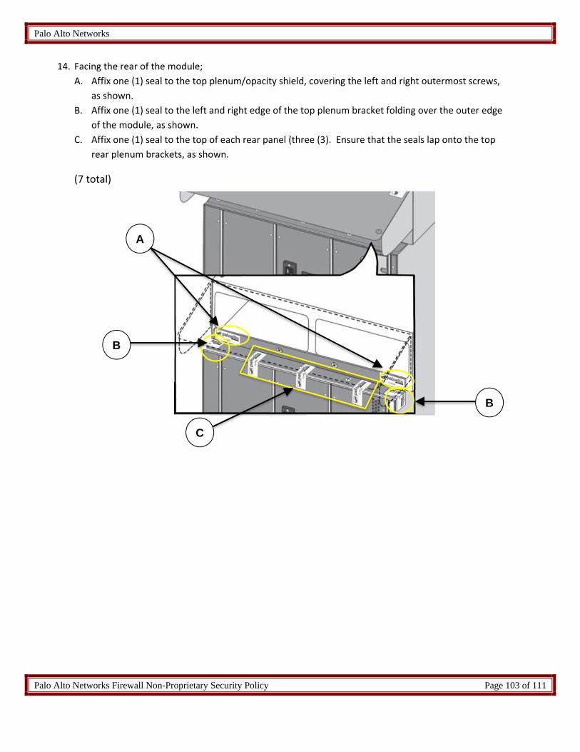
Palo Alto Networks
Palo Alto Networks Firewall Non-Proprietary Security Policy Page 103 of 111
14. Facing the rear of the module;
A. Affix one (1) seal to the top plenum/opacity shield, covering the left and right outermost screws,
as shown.
B. Affix one (1) seal to the left and right edge of the top plenum bracket folding over the outer edge
of the module, as shown.
C. Affix one (1) seal to the top of each rear panel (three (3). Ensure that the seals lap onto the top
rear plenum brackets, as shown.
(7 total)
A
B
B
C

Palo Alto Networks
Palo Alto Networks Firewall Non-Proprietary Security Policy Page 104 of 111
15. Facing the rear of the module,
A. Affix one (1) seal to the bottom of each rear panel (three (3). Ensure that the seals laps onto the bottom
rear plenum brackets, as shown.
B. Affix one (1) seal to the left and right edge of the bottom plenum bracket folding over the outer edge of
the module, as shown.
C. Affix one (1) seal to the bottom plenum’s rear side and the bottom plenum rear bracket.
(6 total)
A
B B
C

Palo Alto Networks
Palo Alto Networks Firewall Non-Proprietary Security Policy Page 105 of 111
16. Facing the rear of the module;
Affix one (1) seal to cover one (1) screw for each power switch, as shown.
Affix one (1) seal to the top and bottom of the vent opacity shield, as shown. Please ensure that
the captive screw is covered.
(6 total)
A B

Palo Alto Networks
Palo Alto Networks Firewall Non-Proprietary Security Policy Page 106 of 111
22 Appendix K ‐ PA‐7080 ‐ FIPS Accessories/Tamper Seal Installation (10 Seals)
1. Using the supplied screws attach the Cable Manger Kit with upper opacity lip to the front of the PA‐
7080, as shown.

Palo Alto Networks
Palo Alto Networks Firewall Non-Proprietary Security Policy Page 107 of 111
2. Using the supplied screws, attach the Left and Right Front Cover brackets to the sides of the PA‐7080,
as shown.
3. Using the supplied screws attach front opacity shield to the PA‐7080 as shown.

Palo Alto Networks
Palo Alto Networks Firewall Non-Proprietary Security Policy Page 108 of 111
4. The final assembly for the PA‐7080 with the FIPS kit is as shown.

Palo Alto Networks
Palo Alto Networks Firewall Non-Proprietary Security Policy Page 109 of 111
5. Facing the front of the PA‐7080:
A. Affix one (1) seal to the front and center of the exhaust fan tray. Ensure the seal overlaps the
seam with the front PA‐7080 branding panel as shown. (1 total)
B. Affix one (1) seal to the left and right outer edge of mounting flanges for the front opacity shield.
Seals should fold over the edge of the cover flange and mounting bracket onto the side of the PA‐
7080. (2 total)
C. Affix one (1) seal to the front and center of the air intake fan tray. Ensure the seal overlaps the
seam with the PA‐7080 electrostatic discharge port panel as shown. (1 total)

Palo Alto Networks
Palo Alto Networks Firewall Non-Proprietary Security Policy Page 110 of 111
6. Facing the rear of the PA‐7080;
D. Affix one (1) seal to the left and right outer edge of the upper back panel. Seals should be placed
just below the rear exhaust vent as shown. Seals should wrap around onto the sides of the PA‐
7080 (2 total).
E. Affix one (1) seal to the left and right outer edges of each power entry module as shown. Seals
should wrap around onto the sides of the PA‐7080 (4 total).

Palo Alto Networks
Palo Alto Networks Firewall Non-Proprietary Security Policy Page 111 of 111
23 Appendix L ‐ PA‐220R‐ FIPS Accessories/Tamper Seal Installation (5 Seals)
The PA‐220R requires five (5) seals:
Figure 65 ‐ Top/Rear view of the PA‐220R
Figure 66 ‐ Bottom/Front view of the PA‐220R