P6245 1.5 GHz 10X Active Probe Instruction Manual
214
xx P6245 1.5 GHz 10X Active Probe *P070899505* 070-8995-05 Instruction Manual Manuel d’utilisation Benutzerhandbuch Manual de instrucciones
Transcript of P6245 1.5 GHz 10X Active Probe Instruction Manual
xx
P62451.5 GHz 10X Active Probe
*P070899505*
070-8995-05
Instruction ManualManuel d’utilisationBenutzerhandbuchManual de instrucciones


P62451.5 GHz 10X Active Probe
ZZZ
Instruction Manual
xx
www.tektronix.com070-8995-05

Copyright © Tektronix. All rights reserved. Licensed software products are
owned by Tektronix or its subsidiaries or suppliers, and are protected by
national copyright laws and international treaty provisions.
Tektronix products are covered by U.S. and foreign patents, issued and
pending. Information in this publication supercedes that in all previously
published material. Specifications and price change privileges reserved.
TEKTRONIX and TEK are registered trademarks of Tektronix, Inc.
Contacting Tektronix
Tektronix, Inc.
14200 SW Karl Braun Drive
P.O. Box 500
Beaverton, OR 97077
USA
For product information, sales, service, and technical support:
� In North America, call 1-800-833-9200.
� Worldwide, visit www.tektronix.com to find contacts in your area.

Warranty
Tektronix warrants that this product will be free from defects in materials andworkmanship for a period of one (1) year from the date of shipment. If any such productproves defective during this warranty period, Tektronix, at its option, either will repairthe defective product without charge for parts and labor, or will provide a replacementin exchange for the defective product. Parts, modules and replacement products used byTektronix for warranty work may be new or reconditioned to like new performance. Allreplaced parts, modules and products become the property of Tektronix.
In order to obtain service under this warranty, Customer must notify Tektronix of thedefect before the expiration of the warranty period and make suitable arrangements for theperformance of service. Customer shall be responsible for packaging and shipping thedefective product to the service center designated by Tektronix, with shipping chargesprepaid. Tektronix shall pay for the return of the product to Customer if the shipment is toa location within the country in which the Tektronix service center is located. Customershall be responsible for paying all shipping charges, duties, taxes, and any other chargesfor products returned to any other locations.
This warranty shall not apply to any defect, failure or damage caused by improper use orimproper or inadequate maintenance and care. Tektronix shall not be obligated to furnishservice under this warranty a) to repair damage resulting from attempts by personnel otherthan Tektronix representatives to install, repair or service the product; b) to repair damageresulting from improper use or connection to incompatible equipment; c) to repair anydamage or malfunction caused by the use of non-Tektronix supplies; or d) to service aproduct that has been modified or integrated with other products when the effect of suchmodification or integration increases the time or difficulty of servicing the product.
THIS WARRANTY IS GIVEN BY TEKTRONIX WITH RESPECT TO THEPRODUCT IN LIEU OF ANY OTHER WARRANTIES, EXPRESS OR IMPLIED.TEKTRONIX AND ITS VENDORS DISCLAIM ANY IMPLIED WARRANTIES OFMERCHANTABILITY OR FITNESS FOR A PARTICULAR PURPOSE. TEKTRONIX’RESPONSIBILITY TO REPAIR OR REPLACE DEFECTIVE PRODUCTS IS THESOLE AND EXCLUSIVE REMEDY PROVIDED TO THE CUSTOMER FORBREACH OF THIS WARRANTY. TEKTRONIX AND ITS VENDORS WILL NOT BELIABLE FOR ANY INDIRECT, SPECIAL, INCIDENTAL, OR CONSEQUENTIALDAMAGES IRRESPECTIVE OF WHETHER TEKTRONIX OR THE VENDOR HASADVANCE NOTICE OF THE POSSIBILITY OF SUCH DAMAGES.
[W2 – 15AUG04]


P6245 Instruction Manual i
Table of Contents
Getting Started
Product Description 1--1. . . . . . . . . . . . . . . . . . . . . . . . . . . . . . . . .Standard Accessories 1--1. . . . . . . . . . . . . . . . . . . . . . . . . . . . . . . . .Customer Support 1--2. . . . . . . . . . . . . . . . . . . . . . . . . . . . . . . . . . .
Features and Accessories 1--3. . . . . . . . . . . . . . . . . . . . . . . . . . . . .
Configuration 1--7. . . . . . . . . . . . . . . . . . . . . . . . . . . . . . . . . . . . . .Probe Offset 1--7. . . . . . . . . . . . . . . . . . . . . . . . . . . . . . . . . . . . . . . .
Functional Check 1--9. . . . . . . . . . . . . . . . . . . . . . . . . . . . . . . . . . .
Operating Basics
Operating Basics 2--1. . . . . . . . . . . . . . . . . . . . . . . . . . . . . . . . . . .Maximum Non-destructive Input Voltage 2--1. . . . . . . . . . . . . . . . .Input Linear Dynamic Range 2--1. . . . . . . . . . . . . . . . . . . . . . . . . .Ground Lead Length 2--2. . . . . . . . . . . . . . . . . . . . . . . . . . . . . . . . .
Helpful Hints 2--5. . . . . . . . . . . . . . . . . . . . . . . . . . . . . . . . . . . . . .Low-inductance Grounding 2--5. . . . . . . . . . . . . . . . . . . . . . . . . . . .SureFoot™ Grounding 2--6. . . . . . . . . . . . . . . . . . . . . . . . . . . . . . . .Probe Tip Test Points 2--7. . . . . . . . . . . . . . . . . . . . . . . . . . . . . . . . .Probe Tip Stabilization 2--8. . . . . . . . . . . . . . . . . . . . . . . . . . . . . . .
Specifications

Table of Contents
ii P6245 Instruction Manual
List of Figures
Figure 1--1: Dynamic and Offset Limitations 1--8. . . . . . . . . . . . . .Figure 1--2: Probe Functional Check Connections 1--9. . . . . . . . . .
Figure 2--1: Waveform Distortion from Ground Lead Length 2--2.Figure 2--2: Ground Lead Equivalent Circuit 2--3. . . . . . . . . . . . . .Figure 2--3: Low-inductance Grounding 2--5. . . . . . . . . . . . . . . . . .Figure 2--4: Using a SureFoot Adapter for Grounding 2--6. . . . . . .Figure 2--5: Using a Probe Tip as a Test Point 2--7. . . . . . . . . . . . .Figure 2--6: Probe Tip Stabilizing Notch 2--8. . . . . . . . . . . . . . . . .
Figure 3--1: Typical Bandwidth 3--3. . . . . . . . . . . . . . . . . . . . . . . . .Figure 3--2: Typical Voltage Derating vs. Frequency 3--3. . . . . . . .Figure 3--3: Typical Linearity Error vs VIN 3--4. . . . . . . . . . . . . . .Figure 3--4: Typical Input Impedance vs. Frequency 3--4. . . . . . . .Figure 3--5: Typical Phase vs. Frequency 3--5. . . . . . . . . . . . . . . . .

P6245 Instruction Manual iii
General Safety Summary
Review the following safety precautions to avoid injury and preventdamage to this product or any products connected to it.
Only qualified personnel should perform service procedures.
Injury Precautions
Avoid Electric Overload
To avoid electric shock or fire hazard, do not apply a voltage to aterminal that is outside the range specified for that terminal.
Do Not Operate Without Covers
To avoid electric shock or fire hazard, do not operate this productwith covers or panels removed.
Do Not Operate in Wet/Damp Conditions
To avoid electric shock, do not operate this product in wet or dampconditions.
Do Not Operate in Explosive Atmosphere
To avoid injury or fire hazard, do not operate this product in anexplosive atmosphere.

General Safety Summary
iv P6245 Instruction Manual
Product Damage Precautions
Do Not Operate With Suspected Failures
If you suspect there is damage to this product, have it inspected byqualified service personnel.
Do Not Immerse in Liquids
Clean the probe using only a damp cloth. Refer to cleaninginstructions.
Safety Terms and Symbols
Terms in This Manual
These terms may appear in this manual:
WARNING. Warning statements identify conditions or practices that
could result in injury or loss of life.
CAUTION. Caution statements identify conditions or practices that
could result in damage to this product or other property.

P6245 Instruction Manual v
Manual Organization
User Information
This section contains the information necessary to install and use theP6245.
� Getting Started
This section contains the product description, description ofaccessories, probe setup configuration, and how to check the probefor normal operation.
� Operating Basics
This section contains basic information and operating suggestions foroptimal probe performance
� Specifications
Service Information
This section contains the information necessary to maintain andservice the P6245.
� Theory of Operation
� Performance Verification
� Adjustments
� Maintenance
� Troubleshooting
Replaceable Parts List

Manual Organization
vi P6245 Instruction Manual

Getting Started


P6245 Instruction Manual 1- 1
Product Description
The Tektronix P6245 is a 1.5 GHz (probe only), 10X active FETprobe with less than 1 pF input capacitance. The P6245’s low inputcapacitance and high input resistance minimize circuit loading over awide bandwidth range. The P6245’s small profile and low-mass headmakes probing crowded circuits by hand fast and easy. The accessorytips and adapters enable the P6245 to be used on a wide variety ofcircuit architectures.
The P6245 is powered through a TEKPROBE interface between theprobe’s compensation box and the oscilloscope. The P6245 may beused with non-TEKPROBE oscilloscopes and instruments by usingthe optional Tektronix 1103 Probe Power Supply.
In order to fully appreciate the probe’s capabilities, please read theGetting Started and Operating Basics sections of this manual.
Standard Accessories
The P6245 is shipped with the following standard accessories:
� standard probe tips
� SMT KlipChip™ microcircuit test leads
� Y-lead adapter
� right-angle adapter
� signal-ground adapters
� three- and six-inch ground leads
� low-inductance ground lead
� marker rings
� Instruction Manual
For part number information for standard and optional accessories,refer to the Replaceable Parts section of this manual.

Product Description
1- 2 P6245 Instruction Manual
Customer Support
To help you get the best performance from your probe, Tektronixoffers the following customer support services:
Operational Support
If you need assistance using your probe, please call our CustomerSupport Center at 1-800-TEK-WIDE (1-800-835-9433), extension2400. If you are outside the United States or Canada, please contactyour nearest Tektronix Service Center.
Service Support
Should your probe need repair that is beyond that supported by thismanual, please contact your nearest Tektronix Service Center.
Sales Support
To order optional equipment and accessories, call the TektronixNational Marketing Center at 1-800-426-2200. If you are outside theUnited States or Canada, please contact your nearest TektronixService Center.

P6245 Instruction Manual 1- 3
Features and Accessories
The P6245 is provided with several features and accessories designedto make probing and measurement a simpler task. Please take amoment to familiarize yourself with these items and their uses.
Probe TipSocket
GroundSocket
StabilizationNotch
Probe Head Assembly. The probe head isdesigned for ease of use and high performance.Its small size makes it easy to handle in tightareas.
The probe tip socket is sized to easily press onto0.025 inch pins for direct access. The groundsocket provides a short ground path for highfidelity ground connections.
The stabilization notch permits you to useadjacent pins to reduce stresses on the probeand pins. See pages 1--5 and 2--8 for moreinformation.
TEKPROBE™ Interface. The TEKPROBEinterface provides a communication path betweenthe probe and the oscilloscope. Contact pinsprovide power, signal, offset, and probecharacteristic data transfer. See page 4--2 formore information.
If your oscilloscope does not support theTEKPROBE interface, you can use the optional1103 probe power supply as an effectiveinterface. Contact your local Tektronix representa-tive for more information.
Push-In Probe Tip
Push-in Probe Tip. Use the push-in probe tipfor general purpose probing by hand. The tip mayalso be used as a temporary test point. See page2--7 for more information.
The push-in probe tip may also be used with theother socketed leads and adapters.
Features and Accessories
1- 4 P6245 Instruction Manual
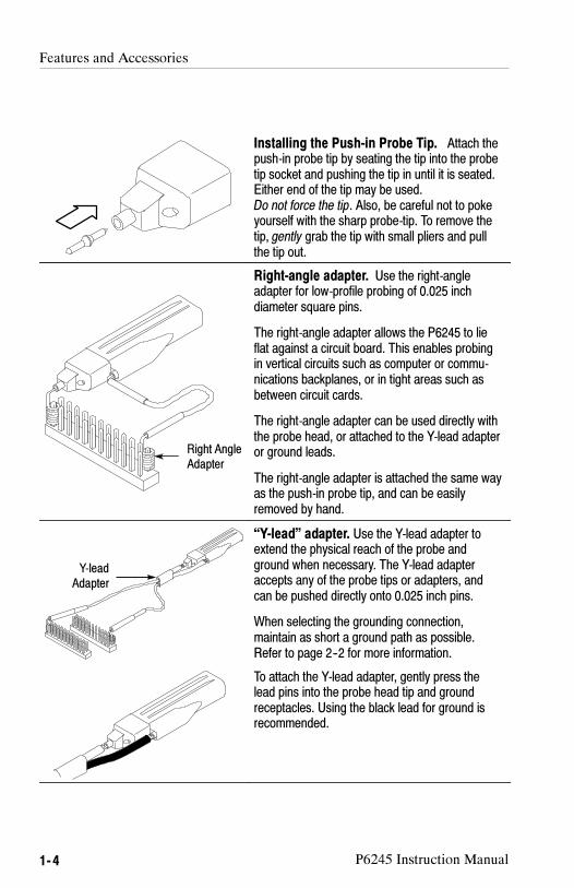
Installing the Push-in Probe Tip. Attach thepush-in probe tip by seating the tip into the probetip socket and pushing the tip in until it is seated.Either end of the tip may be used.Do not force the tip. Also, be careful not to pokeyourself with the sharp probe-tip. To remove thetip, gently grab the tip with small pliers and pullthe tip out.
Right AngleAdapter
Right-angle adapter. Use the right-angleadapter for low-profile probing of 0.025 inchdiameter square pins.
The right-angle adapter allows the P6245 to lieflat against a circuit board. This enables probingin vertical circuits such as computer or commu-nications backplanes, or in tight areas such asbetween circuit cards.
The right-angle adapter can be used directly withthe probe head, or attached to the Y-lead adapteror ground leads.
The right-angle adapter is attached the same wayas the push-in probe tip, and can be easilyremoved by hand.
Y-leadAdapter
“Y-lead” adapter. Use the Y-lead adapter toextend the physical reach of the probe andground when necessary. The Y-lead adapteraccepts any of the probe tips or adapters, andcan be pushed directly onto 0.025 inch pins.
When selecting the grounding connection,maintain as short a ground path as possible.Refer to page 2--2 for more information.
To attach the Y-lead adapter, gently press thelead pins into the probe head tip and groundreceptacles. Using the black lead for ground isrecommended.

Features and Accessories
P6245 Instruction Manual 1- 5
3 and 6 inch ground leads. Use the three- andsix-inch ground leads for general probing. Thesocketed end of the leads may be connected toany of the probe tips and adapters, or fitted onto0.025 inch pins.
To attach the ground leads, press and rotate thelead pin connector into the ground socket on theprobe head. The lead may be removed by simplypulling the pin out by hand.
When selecting the grounding connection,maintain as short a ground path as possible.Refer to page 2--2 for more information.
Low-inductance ground lead. Use thelow-inductance ground adapter to substantiallyreduce ground lead inductance. Because theground lead simply touches the ground reference,you can easily move the probe to different pointson the device under test.
To attach, press the ground lead into the probehead gound socket.
When selecting the grounding connection,maintain as short a ground path as possible.Refer to page 2--2 for more information.
Signal GroundAdapter
FlexLeadAdapter
Signal-Ground Adapter. The signal-groundadapter is ideal for use with signal/ground pairson 0.100 inch header pins (such as FlexLead™adapters).
Attach the signal-ground adapter by gentlypressing it into the ground socket on the probehead.
Be sure to use the stabilization notch wheneverpossible. See page 2--8 for further details.

Features and Accessories
1- 6 P6245 Instruction Manual
KlipChip
Y-leadAdapter
SMT KlipChip™. Use the SMT KlipChip testclips to access fragile, dense circuitry.
KlipChip test clips can be connected to the Y-leador three- or six-inch ground leads. Simply pressthe lead socket into the KlipChip handle.
The KlipChip body freely turns, allowing betterprobe orientation. To reduce stress and provide alower profile on components being tested, theflexible sleeve of the KlipChip bends up to a35 degree angle.
Color MarkerBands
Color Marker Bands. Attach matching pairs ofthe color marker bands onto the cable at the headand compensation box of each probe. The markerbands enable quick verification of which probe isconnected to which instrument channel.
SureFoot™ probe tip (optional). TheSureFoot tip is an integral probe tip and miniatureguide that enables fault-free probing of fine-pitchSMD packages. Attach the SureFoot adapters thesame way as the push-in probe tips. They can beused with any of the socketed accessory leads.
The yellow, 0.050 inch SureFoot tip is compatiblewith 50 mil JEDEC packages such as SOIC,PLCC, CLCC, etc.
The blue, 0.025 inch SureFoot tip is compatiblewith 0.65 mm JEDEC and EIAJ packages.
The red, 0.5 mm SureFoot tip is compatible withEIAJ packages.
P6245 Instruction Manual 1- 7
Configuration
The P6245 provides the oscilloscope with the probe model number,serial number, and attenuation factor. When connected to aTEKPROBE oscilloscope, display readouts are corrected for theprobe attenuation factor, the instrument input is set to 50 Ω, and thecoupling is set to DC.
CAUTION. Do not attempt to install the P6245 on a non-TEKPROBE
connector. Damage to the probe and connector may result. If youroscilloscope does not support the TEKPROBE interface, use the
optional Tektronix 1103 Probe Power Supply.
If the P6245 is used with the Tektronix 1103 Probe Power Supply, be
sure to have a 50 Ω termination at the oscilloscope. Also, set the
oscilloscope channel coupling to DC.
The probe offset control is controlled by the oscilloscope. If theoscilloscope used does not support the TEKPROBE interface, theoffset controls on the optional Tektronix 1103 Probe Power Supplycan be used.
Probe Offset
The probe offset is adjustable to permit operation within the probe’slinear range. Using the offset to cancel DC signal componentsenables optimal probe performance. See Figure 1--1 on page 1--8.
NOTE. See your oscilloscope manual for specific instructions on its
operation and offset control.

Configuration
1- 8 P6245 Instruction Manual
To set the probe offset, follow these steps:
1. Set the oscilloscope coupling to GND.
2. Use the vertical position control to set a zero reference level onthe oscilloscope display.
3. Set the oscilloscope coupling to DC and 5 V/div.
4. Attach the probe to the circuit.
5. Adjust the probe offset to bring the trace to the oscilloscope zeroreference.
6. Change the volts/division setting to the desired range, adjustingthe offset to keep the trace on the zero reference level.
NOTE. The P6245 has a ±10 V offset range. The linear operating
range is ±8 V. See Figure 1--1. Also, see page 2--1 for moreinformation.
If cursors are used on a TEKPROBE oscilloscope, the zero reference
will be at the probe offset voltage.
0 V
+15 V
--15 V
+8 V
--8 V
+10 V
--10 V
Nonoperating Range (+15 V Maximum Non-destructive Input Voltage )
+10 V
--10 V
Nonoperating Range (--15 V Maximum Non-destructive Input Voltage )
Maximum Offset RangeMaximum AC Signal Amplitude
Figure 1- 1: Dynamic and Offset Limitations

P6245 Instruction Manual 1- 9
Functional Check
After installing the probe on the oscilloscope, a functional checkmay be performed using the PROBE COMPENSATION connec-tions on the front panel of the oscilloscope. See Figure 1--2.
Figure 1- 2: Probe Functional Check Connections
1. Connect the probe to the oscilloscope.
2. Set the oscilloscope to display the probe’s channel.
3. Using a ground lead and a SMT KlipChip, connect the probeground to the PROBE COMPENSATION ground connection onthe oscilloscope.
4. Using a standard tip, hold the probe to the SIGNAL terminal onthe oscilloscope.
5. Press AUTOSET (or adjust the oscilloscope) to display thecalibration waveform.

Functional Check
1- 10 P6245 Instruction Manual
NOTE. If your instrument supports probe calibration routines, now isa good time to perform them.
6. Disconnect the probe from the SIGNAL terminal and ground theprobe tip. (Connect the KlipChip to the probe tip.)
7. With the probe offset set to 0.0 V, the oscilloscope display shouldbe at the ground reference.
8. Set the oscilloscope volts/division to 5 V.
9. Adjust the probe offset. The displayed waveform should varybetween approximately +10 V and --10 V. (A +10 V offsetdisplays a --10 V level on your instrument.)
NOTE. If no waveform is displayed, check the vertical coupling to be
sure that it is set to DC.
If the offset adjustment has no effect, set the vertical coupling to DC.
If you are using the Tektronix 1103 Probe Power Supply, and thewaveform is distorted, check to make sure that the oscilloscope
termination is 50 Ω.
If the probe does not pass this functional check, go to the Trouble-shooting section of this manual.

Operating Basics


P6245 Instruction Manual 2- 1
Operating Basics
Please follow these operating guidelines to get optimum performancefrom your P6245.
Maximum Non-destructive Input Voltage
The P6245 is electrically protected against static voltage; however,applying voltages above its design limits may damage the probe tipamplifier. Please refer to the Specifications section of this manual forthe maximum operating voltage and frequency derating information.
Input Linear Dynamic Range
The probe head amplifier used by the P6245 has a limited linearoperating range. To keep the input linearity error less than 4% youmust limit the signal input voltage to ±8 V (including any DC offset).
Use the DC offset adjustment to maintain the probe within itsdynamic range. The nominal offset adjustment range of the P6245 is±10 VDC. For example: to offset a +5 VDC level in a circuit, set theoffset to +5 V.

Operating Basics
2- 2 P6245 Instruction Manual
Ground Lead Length
When you are probing a circuit, you should always use as short aground lead as possible between the probe head and circuit ground.
The series inductance added by the probe tip and ground lead canresult in a resonant circuit; this circuit may cause parasitic “ringing”within the bandwidth of your oscilloscope. Refer to Figure 2--1.
Low-inductanceGround
Three-inchGround
Six-inchGround
Figure 2- 1: Waveform Distortion from Ground Lead Length
Ground Lead Inductance
When you touch your probe tip to a circuit element, you areintroducing a new resistance, capacitance, and inductance into thecircuit. Refer to Figure 2--2.

Operating Basics
P6245 Instruction Manual 2- 3
R source
V source
Probe C in1 pF
Probe R in1 MΩ
L gl (Ground Lead)
Figure 2- 2: Ground Lead Equivalent Circuit
Ringing and rise time degradation can be masked if the frequencycontent of the signal degradation is beyond the bandwidth of theoscilloscope.
You can determine if ground lead effects may be a problem in yourapplication if you know the self-inductance (L) and capacitance (C)of your probe and ground lead. Calculate the approximate resonantfrequency (f0) at which this parasitic circuit will resonate with thefollowing formula:
f0 =1
2π LC�
The preceding equation shows that reducing the ground leadinductance will raise the resonant frequency. If your measurementsare affected by ringing, your goal is to lower the inductance of yourground path until the resulting resonant frequency is well above thefrequency of your measurements.
The low-inductance ground contacts described in Accessories canhelp you reduce the effects of ground lead inductance on yourmeasurements.

Operating Basics
2- 4 P6245 Instruction Manual

P6245 Instruction Manual 2- 5
Helpful Hints
Follow these helpful hints to make probing easier and noise free.
Low-inductance Grounding
Placing a ground plane on top of a package being probed canminimize ground lead length and inductance. See Figure 2--3.
Figure 2- 3: Low-inductance Grounding
Attach a small piece of copper clad on top of the package andconnect it to the package ground connection. Use the low-inductanceground lead provided with the P6245 to keep the ground lead lengthas short as possible.
This method is very useful when making many measurements on thesame package. Using a ground plane on the package makes probingthe package easier, and avoids adding unnecessary ground leadlength and distortion.

Helpful Hints
2- 6 P6245 Instruction Manual
SureFoot™ Grounding
If you cannot use the low-inductance grounding method recom-mended, the probe may be grounded to the package under test usinga SureFoot adapter. Refer to Figure 2--4.
Figure 2- 4: Using a SureFoot Adapter for Grounding
Use a SureFoot adapter at the end of a short ground lead to connectdirectly to the package ground. This method is preferred over usingan adjacent circuit ground because it is the shortest ground pathpossible.

Helpful Hints
P6245 Instruction Manual 2- 7
Probe Tip Test Points
The push-in probe tip or a 0.025 square pin can be soldered into acircuit to be used as a temporary test point. See Figure 2--5.
Solder the tip onto a lead or pin with a low-power soldering iron.Press the probe head onto the tip to make a measurement, and thenpull the probe head off when you are done.
The probe tip may be removed and reused by desoldering it from thecircuit, and soldering it into another circuit in the future.
Solder
Figure 2- 5: Using a Probe Tip as a Test Point
NOTE. It is not recommended that pieces of solid-core copper wire be
used as test points. If the wire breaks off in the probe tip socket, it
may be impossible to remove the wire, and it will prevent insertion ofother accessory tips.

Helpful Hints
2- 8 P6245 Instruction Manual
Probe Tip Stabilization
The P6245 probe head has a stabilizing notch for use with 0.100 inchspaced header pins. See the probe head detail on page 1--3.
As the probe is pressed onto the header pin, an adjacent pin can beinserted into the probe’s stabilizing notch. See Figure 2--6. Thisprevents unnecessary force from being applied directly to the probetip or pins.
Stabilization Notch
Figure 2- 6: Probe Tip Stabilizing Notch
The signal-ground adapter then rests on the stabilized pin without arisk of its moving out of place.

Specifications


P6245 Instruction Manual 3- 1
Specifications
These specifications apply to a P6245 when used with a TDS 684Aoscilloscope.
The probe and instrument must first be allowed to warm up for20 minutes before measurements are taken.
CAUTION. Do not apply voltages beyond the non-destructive input
voltage range to the probe. Damage to the probe or circuit under test
may result.
Table 3- 1: Warranted Electrical Specifications
Analog Bandwidth (system) 1 GHz
DC Attenuation Accuracy(probe only)
10:1 ±2%
Output Zero ±5 mV or less at output of probe
±50 mV or less displayed on screen withTEKPROBE interface
Rise Time (probe only) 267 ps on ≥10 GHz oscilloscope

Specifications
3- 2 P6245 Instruction Manual
Table 3- 2: Typical Electrical Characteristics
Analog Bandwidth (probe only) 1.5 GHz on ≥10 GHz oscilloscope(See Figure 3--1.)
Linear Input Dynamic Range -- 8 V to + 8 V.(Equivalent to -- 0.8 V to + 0.8 Vat the output of the probe.)
Linearity �4% or less of dynamic range
Non--Destructive Input Voltage Range -- 15 V to + 15 V (DC + peak AC)(See Figure 3--2.)
Input Resistance 1 MΩ at DC. (See Figure 3--4)
Input Capacitance ≤1.0 pF
Offset Range --10 V to +10 V
DC Offset Drift 100 �V/°C or less at output of probe
1 mV/°C or less displayed on screen withTEKPROBE interface
Delay Time 5.3 ns ±0.2 ns

Specifications
P6245 Instruction Manual 3- 3
0 dB
--1 dB
--2 dB
--3 dB
--4 dB
--5 dB
--6 dB
--7 dB
--8 dB
+1 dB
+2 dB
1 MHz 1 GHz100 MHz10 MHz
Figure 3- 1: Typical Bandwidth
25 V
20 V
15 V
1 MHz 10 MHz 100 MHz
5 V
0 V
10 V
10V at 1 GHz
6V at 3 GHz
1 GHz
Figure 3- 2: Typical Non-Destructive Peak Volt. Derating vs. Frequency

Specifications
3- 4 P6245 Instruction Manual
--20 V 0 V--10 V 10 V 20 V
150 mV
100 mV
50 mV
--100 mV
0 mV
--50 mV
--150 mV
Display
Error
VIN
Figure 3- 3: Typical Linearity Error vs VIN
10 MΩ
1 MΩ
100 kΩ
10kΩ
1 kΩ
100Ω
10Ω
100 Hz 1 GHz100 kHz1 kHz 10 kHz 1 MHz 10 MHz 100 MHz
Figure 3- 4: Typical Input Impedance vs. Frequency
Specifications
P6245 Instruction Manual 3- 5
20°
0°
--20°
--40°
100 Hz 1 GHz100 kHz1 kHz 10 kHz 1 MHz 10 MHz 100 MHz
--80°
--100°
--60°
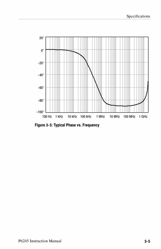
Figure 3- 5: Typical Phase vs. Frequency

Specifications
3- 6 P6245 Instruction Manual
Table 3- 3: Physical Characteristics
Net Weight 63.8 g (2.25 ounces)
Cable Length 1.3 meter
Table 3- 4: Environmental Characteristics
Operating Temperature 0° C TO +50° C.
The environmental exposure is the procedure statedin Tektronix Design Standard 062--2847--00 for Class5 equipment.
Non--operating Temperature -- 40° C TO + 71° C.
The environmental exposure is the procedure statedin Tektronix Design Standard 062--2847--00 for Class5 equipment.
Humidity The environmental exposure is the procedure statedin Tektronix Design Standard 062--2847--00 for Class5 equipment.
Packaged Product Vibration andShock
The packaged product qualifies under the DistributionCycle 1 Assurance Level II for packaged products 0 --20 lbs. Test 2 for Warehouse and Vehicle Stacking(Compression) is omitted.
Tektronix standard 062--2858--00, Rev. B, Class 5.
Altitude Operating: 15,000 ft.Non-Operating: 50,000 ft.

Français


P6245Sonde active 10X 1,5 GHz
ZZZ
Manuel d’utilisation
xx
www.tektronix.com070-8995-05

Copyright © Tektronix. Tous droits réservés. Les produits logiciels souslicence sont la propriété de Tektronix, de ses filiales ou de ses fournisseurs etsont protégés par les lois nationales sur le copyright, ainsi que par des traitésinternationaux.
Les produits Tektronix sont protégés par des brevets américains et étrangers déjàdéposés ou en cours d’obtention. Les informations contenues dans le présentdocument remplacent celles publiées précédemment. Les spécifications et lesprix peuvent être soumis à modification.
TEKTRONIX et TEK sont des marques déposées de Tektronix, Inc.
Coordonnées de TektronixTektronix, Inc.14200 SW Karl Braun DriveP.O. Box 500Beaverton, OR 97077Etats-Unis
Pour obtenir des informations sur le produit, la vente, les services et l’assistancetechnique :
En Amérique du Nord, appelez le 1-800-833-9200.Pour les autres pays, visitez le site www.tektronix.com pour connaître les
coordonnées locales.

Garantie
Tektronix garantit que ce produit est exempt de défaut au niveau des matériaux et de lafabrication, pendant une période de un (1) an à compter de la date d’expédition. Si unproduit Tektronix se révèle défectueux pendant sa période de garantie, Tektronix peutsoit réparer le produit en question, en prenant à sa charge les frais de main-d’œuvre etde pièces, soit fournir un produit de remplacement en échange de celui défectueux. Lespièces, modules et produits de remplacement utilisés par Tektronix pour des travaux sousgarantie peuvent être neufs ou reconditionnés pour de nouvelles performances. Tous lesproduits, modules et pièces de rechange deviennent la propriété de Tektronix.
Pour pouvoir prétendre à la garantie, le client doit signaler le défaut à Tektronix avantl’expiration de la période de garantie et effectuer les démarches correspondantes. Ilappartient au client d’emballer et d’expédier en port payé le produit défectueux aucentre de réparation indiqué par Tektronix. Tektronix prend à sa charge la réexpéditiondu produit au client, si le destinataire se trouve dans le pays où le centre de réparationTektronix est implanté. Tous les frais d’expédition, droits, taxes et autres coûts afférents àla réexpédition du produit dans un autre lieu sont à la charge du client.
Cette garantie est caduque en cas de défaillance, de panne ou de dommage provoqué parun usage impropre ou un défaut de soin ou de maintenance. Tektronix n’est pas contraintd’assurer les réparations sous garantie dans les cas suivants : a) réparations résultantde dommages provoqués par un personnel non mandaté par Tektronix qui a installé,réparé ou entretenu le produit ; b) réparations résultant d’une utilisation impropre oud’un raccordement à des équipements incompatibles ; c) réparation de dommages ou dedysfonctionnements résultant de l’utilisation de pièces non fournies par Tektronix ; ou d)entretien d’un produit modifié ou intégré à d’autres produits, rendant ainsi le produit plusdifficile à entretenir ou augmentant la périodicité des entretiens.
LA PRESENTE GARANTIE DEFINIE PAR TEKTRONIX EU EGARD AU PRODUITTIENT LIEU DE TOUTE AUTRE GARANTIE, EXPLICITE OU IMPLICITE.TEKTRONIX ET SES FOURNISSEURS NE DONNENT AUCUNE GARANTIEIMPLICITE QUANT A LA QUALITE MARCHANDE OU A L’ADEQUATION DUPRODUIT A DES USAGES PARTICULIERS. LE SEUL RECOURS DU CLIENT ENCAS DE VIOLATION DE CETTE GARANTIE EST D’EXIGER DE TEKTRONIXQU’IL REPARE OU REMPLACE LE PRODUIT DEFECTUEUX. TEKTRONIXET SES FOURNISSEURS NE POURRONT PAR CONSEQUENT PAS ETRETENUS POUR RESPONSABLES DES DOMMAGES INDIRECTS, SPECIAUXOU CONSECUTIFS, MEME S’ILS SONT INFORMES AU PREALABLE DEL’EVENTUALITE DES DOMMAGES EN QUESTION.
[W2 – 15AUG04]


Manuel d’utilisation -- P6245 i
Table des matières
Mise en route
Description du produit 1--1. . . . . . . . . . . . . . . . . . . . . . . . . . . . . .Accessoires standard 1--1. . . . . . . . . . . . . . . . . . . . . . . . . . . . . . . . .Service clientèle 1--2. . . . . . . . . . . . . . . . . . . . . . . . . . . . . . . . . . . . .
Caractéristiques et accessoires 1--3. . . . . . . . . . . . . . . . . . . . . . . .
Configuration 1--9. . . . . . . . . . . . . . . . . . . . . . . . . . . . . . . . . . . . . .Décalage de sonde 1--9. . . . . . . . . . . . . . . . . . . . . . . . . . . . . . . . . . .
Vérification de fonctionnement 1--12. . . . . . . . . . . . . . . . . . . . . . .
Fonctionnement
Tension d’entrée non destructive maximum 2--1. . . . . . . . . . . . . . .Plage dynamique linéaire d’entrée 2--1. . . . . . . . . . . . . . . . . . . . . .Longueur du fil de masse 2--2. . . . . . . . . . . . . . . . . . . . . . . . . . . . .
Suggestions pratiques 2--5. . . . . . . . . . . . . . . . . . . . . . . . . . . . . . .Mise à la masse à faible inductance 2--5. . . . . . . . . . . . . . . . . . . . .Mise à la masse avec l’adaptateur SureFoot™ 2--6. . . . . . . . . . . . .Points de mesure avec embout de sonde 2--7. . . . . . . . . . . . . . . . . .Stabilisation de l’embout de sonde 2--8. . . . . . . . . . . . . . . . . . . . . .
Caractéristiques techniques

Table des matières
ii Manuel d’utilisation -- P6245
Figures
Figure 1--1: Limites dynamiques et de décalage 1--11. . . . . . . . . . . .Figure 1--2: Connexions de vérification du fonctionnement
de la sonde 1--12. . . . . . . . . . . . . . . . . . . . . . . . . . . . . . . . . . . . . .
Figure 2--1: Distortion du signal selon la longueurdu fil de masse 2--2. . . . . . . . . . . . . . . . . . . . . . . . . . . . . . . . . . .
Figure 2--2: Réseau équivalent du fil 2--3. . . . . . . . . . . . . . . . . . . . .Figure 2--3: Mise à la masse à faible inductance 2--5. . . . . . . . . . .Figure 2--4: Utilisation d’un adaptateur SureFoot pour mise
à la masse 2--6. . . . . . . . . . . . . . . . . . . . . . . . . . . . . . . . . . . . . . .Figure 2--5: Utilisation d’un embout de sonde comme point
de mesure 2--7. . . . . . . . . . . . . . . . . . . . . . . . . . . . . . . . . . . . . . .Figure 2--6: Encoche de stabilisation inductance 2--8. . . . . . . . . . .
Figure 3--1: Bande passante typique 3--3. . . . . . . . . . . . . . . . . . . . .Figure 3--2: Réponse en fréquence typique 3--3. . . . . . . . . . . . . . . .Figure 3--3: Erreur de linéarité typique par rapport
à la tension d’entrée 3--4. . . . . . . . . . . . . . . . . . . . . . . . . . . . . . .Figure 3--4: Impédance d’entrée typique par rapport
à la fréquence 3--4. . . . . . . . . . . . . . . . . . . . . . . . . . . . . . . . . . . .Figure 3--5: Phase typique par rapport à la fréquence 3--5. . . . . . . .

Manuel d’utilisation -- P6245 iii
Consignes de sécurité
Veuillez lire attentivement les consignes ci--dessous concernant laprévention des blessures corporelles et des dommages à l’appareil ouà tout autre produit connecté.
Seul le personnel qualifié est autorisé à effectuer les procéduresd’entretien.
Précautions particulières pour éviter les blessures
Eviter les surcharges électriques
N’appliquez jamais une tension qui excède la plage spécifiée afind’éviter les décharges électriques et les risques d’incendie.
Ne pas utiliser sans capots
Pour prévenir les décharges électriques et les risques d’incendie,n’utilisez jamais ce produit sans ses capots de protection etpanneaux.
Ne pas utiliser dans des conditions humides
Pour prévenir les décharges électriques, n’utilisez pas la sonde dansdes conditions humides.
Ne pas utiliser dans un environnement explosif
Pour prévenir les blessures et les risques d’incendie, n’utilisez pas lasonde dans un environnement potentiellement explosif.

Consignes de sécurité
iv Manuel d’utilisation -- P6245
Précautions à prendre pour éviter d’endommager l’appareil
Ne pas utiliser en cas de défaillance
Si vous détectez une défaillance possible de la sonde, faites--lainspecter par un technicien de maintenance.
Ne pas immerger dans un liquide
Nettoyez la sonde avec un chiffon humide seulement. Reportez--vousaux recommandations de nettoyage.
Symboles et définitions
Termes apparaissant dans ce manuel
Vous trouverez les termes ci--après dans ce manuel :
WARNING. signale des conditions ou actions dangereuses pourl’utilisateur (risques de blessure ou danger de mort).
CAUTION. signale des conditions ou actions qui peuvent provoquerdes dommages au matériel ou à d’autres équipements.

Manuel d’utilisation -- P6245 v
Structure du manuel
Informations d’utilisation
Cette partie présente les informations nécessaires à l’installation et àl’utilisation de la sonde P6245.
� Mise en route
Ce chapitre contient la description du produit et des accessoires, laconfiguration d’installation de la sonde et les modalités devérification de la sonde pour un fonctionnement normal.
� Fonctionnement
Ce chapitre contient des renseignements de base et des suggestionsd’exploitation pour une performance optimale de la sonde.
� Caractéristiques techniques
Informations de maintenance (en anglais)
Cette partie contient les renseignements nécessaires à la maintenanceet à la réparation de la sonde P6245.
� Théorie de fonctionnement (Theory of Operation)
� Vérification des performances (Performance Verification)
� Réglages (Adjustments)
� Maintenance (Maintenance)
� Dépannage (Troubleshooting)
Liste des pièces de rechange (en anglais)

Structure du manuel
vi Manuel d’utilisation -- P6245

Mise en route


Manuel d’utilisation -- P6245 1- 1
Description du produit
La sonde P6245 de Tektronix est une sonde active TEC (transistor àeffet de champ) 10X de 1,5 GHz (sonde uniquement), avec unecapacité d’entrée inférieure à 1 pF. La faible capacité d’entrée et larésistance d’entrée élevée de cette sonde permettent de minimiser lacharge du circuit sur une large bande passante. Par la petite taille etla légèreté de sa tête, la sonde P6245 facilite et accélère les mesuresmanuelles sur les circuits à haute densité. Des embouts et adaptateursaccessoires lui permettent d’être utilisée sur une grande variétéd’architectures de circuits.
La sonde P6245 est alimentée par une interface TEKPROBE situéeentre la boîte de compensation de la sonde et l’oscilloscope. Ellepeut également être utilisée avec des oscilloscopes et instrumentsnon TEKPROBE à l’aide de l’unité d’alimentation de sondesTektronix 1103.
Afin de pleinement apprécier les possibilités de la sonde, veuillezlire les chapitres Mise en route et Fonctionnement de ce manuel.
Accessoires standard
La sonde P6245 est livrée avec les accessoires standard suivants :
� embouts de sonde standard
� fils de test de microcircuit SMT KlipChipTM
� adaptateur en Y
� adaptateur à angle droit
� adaptateurs signal--terre
� fils de masse de 7,6 cm et 15 cm
� fil de masse faible inductance
� bagues repères
� manuel d’utilisation

Description du produit
1- 2 Manuel d’utilisation -- P6245
Pour des renseignements sur les références des accessoires standardet optionnels, reportez--vous au chapitre Replaceable Parts de cemanuel.
Service clientèle
Afin d’obtenir une performance optimale de la sonde P6245,n’hésitez pas à contacter votre centre Tektronix le plus proche :
� pour une assistance dans l’utilisation de votre sonde,
� pour toutes réparations non décrites dans ce manuel,
� pour commander du matériel ou des accessoires supplémentaires.

Manuel d’utilisation -- P6245 1- 3
Caractéristiques et accessoires
La sonde P6245 est dotée de plusieurs caractéristiques et accessoiresconçus pour faciliter les opérations de mesure. Veuillez vousfamiliariser avec ces différents éléments et leur utilisation.
Prise del’emboutde sonde
Prise demise à lamasseEncoche de
stabilisation
Tête de la sonde. La conception de la tête desonde permet une grande facilité d’utilisation etune performance optimale. Sa petite taille faciliteson maniement dans des espaces restreints.
La dimension de la prise de l’embout de sondepermet l’insertion aisée d’embouts de 0,025pouce pour un accès direct. La prise de mise à lamasse fournit une liaison courte à la masse pourdes connexions haute fidélité.
L’encoche de stabilisation permet d’utiliser lesbroches adjacentes pour réduire la contrainte surla sonde et les broches. Voir les pages 1--6 et2--8 pour des renseignements supplémentaires.
Interface TEKPROBE™. L’interfaceTEKPROBE fournit une voie de communicationentre la sonde et l’oscilloscope. Des pointes decontact fournissent l’alimentation, le signal, ledécalage et le transfert de donnéescaractéristiques de la sonde. Voir page 4--2 pourdes renseignements supplémentaires.
Si votre oscilloscope n’accepte pas l’interfaceTEKPROBE, vous pouvez utiliser l’unitéd’alimentation de sonde 1103, en option, commeinterface. Contactez Tektronix pour de plusamples renseignements.

Caractéristiques et accessoires
1- 4 Manuel d’utilisation -- P6245
Embout desonde amovible
Embout de sonde amovible. Utilisez l’emboutde sonde amovible pour les mesures manuellesen général. L’embout peut aussi servir de point demesure temporaire. Voir page 2--7 pour de plusamples renseignements.
L’embout de sonde amovible peut aussi êtreutilisé avec les autres fils et adaptateurs à prisefemelle.
Installation de l’embout de sonde amovibleFixez l’embout de sonde en le positionnant dansla prise de l’embout de sonde et en l’y enfonçantjusqu’à ce qu’il soit en place. Vous pouvez utilisern’importe quelle extrémité de l’embout.
Ne forcez pas sur l’embout. Faites égalementattention à ne pas vous blesser avec l’embout quiest pointu. Pour enlever l’embout, saisissez--ledoucement à l’aide d’une petite pince et retirez--lede la prise.
Adaptateurà angle droit
Adaptateur à angle droit. Utilisez l’adaptateurà angle droit pour les mesures de brochescarrées de 0,025 pouce de diamètre.
L’adaptateur à angle droit permet de poser lasonde P6245 à plat contre la carte à circuits. Cecipermet des mesures dans les circuits verticauxtels que dans les bus d’interconnexion ou dansdes espaces étroits comme entre des cartesélectroniques.
L’adaptateur à angle droit peut être utilisédirectement avec la tête de sonde ou bien fixé àl’adaptateur en Y ou aux fils de mise à la masse.
L’adaptateur à angle droit se fixe de la mêmefaçon que l’embout de sonde amovible et peutêtre facilement retiré à la main.

Caractéristiques et accessoires
Manuel d’utilisation -- P6245 1- 5
Adaptateuren Y
Adaptateur en Y. Utilisez l’adaptateur en Ypour augmenter physiquement la portée de lasonde et de la mise à la masse, si nécessaire.L’adaptateur en Y accepte tous les embouts etadaptateurs et peut être directement inséré dansles broches.
Lorsque vous établissez la connexion à la masse,utilisez un fil aussi court que possible. Reportez--vous à la page 2--1 pour de plus amplesrenseignements.
Pour fixer l’adaptateur, insérez doucement lesbroches dans l’embout et la prise de masse de lasonde. Il est recommandé d’utiliser le fil noir pour lamise à la masse.
Fils de mise à la masse de 7,6 cm et 15 cmUtilisez les fils de mise à la masse de 7,6 cm et15 cm pour les mesures générales. L’extrémitédes fils comportant la prise femelle peut êtreconnectée à tous les embouts et adaptateurs desonde ou sur les broches elles--mêmes.
Pour fixer les fils de masse, insérez en tournant leconnecteur du fil dans la prise de mise à la massesituée sur la tête de sonde. Ces fils se retirentfacilement à la main.
Lorsque vous établissez la connexion à la masse,utilisez un fil aussi court que possible. Reportez--vous à la page 2--1 pour de plus amplesrenseignements.

Caractéristiques et accessoires
1- 6 Manuel d’utilisation -- P6245
Fil de masse faible inductance. Utilisezl’adaptateur de masse à faible inductance pourréduire considérablement l’inductance du fil demasse. Comme le fil de masse ne fait quetoucher la référence masse, vous pouvezaisément déplacer la sonde sur l’unité à tester.
Pour le fixer, insérez le fil de masse dans la prisede masse de la sonde.
Lorsque vous établissez la connexion à la masse,utilisez un fil aussi court que possible. Reportez--vous à la page 2--1 pour de plus amplesrenseignements.
Adaptateursignal--masse
AdaptateursFlexLead
Adaptateur signal-masse. L’adaptateursignal--masse est idéal pour les paires signal/masse sur les broches d’espacement 0,100pouce (tels que les adaptateurs FlexLeadTM).
Pour fixer l’adaptateur, insérez--le doucementdans la prise de masse située sur la tête de lasonde.
N’oubliez pas d’utiliser l’encoche de stabilisationsi possible. Voir page 2--8 pour de plus amplesdétails.

Caractéristiques et accessoires
Manuel d’utilisation -- P6245 1- 7
KlipChip
Adaptateuren Y
KlipChip™ CMS. Utilisez les pinces de testKlipChip CMS pour accéder aux circuits fragileset denses.
Les pinces KlipChip peuvent être connectées aufil en Y ou aux fils de mise à la masse de 7,6 cmou de 15 cm. Il suffit d’insérer la prise du fil dansla poignée du KlipChip.
Le corps du KlipChip tourne librement, ce quipermet une meilleure orientation de la sonde. LeKlipChip se plie jusqu’à un angle de 35 degrés,pour réduire l’encombrement et les contraintessur les composants à tester.
Bagues decouleur
Bagues de couleur. Fixez deux bagues demême couleur sur le câble à la tête et à la boîtede compensation de chaque sonde. Ces baguespermettent de vérifier rapidement quelle sondeest connectée à quelle voie de l’instrument.
Adaptateur SureFoot™ (en option).L’adaptateur SureFoot comprend un embout desonde et un guide miniature qui permet del’utiliser sans erreur avec les composants CMStrès fins. Fixez les adaptateurs SureFoot de lamême façon que les embouts de sondeamovibles. Ils peuvent être utilisés avec tous lesfils accessoires à prise femelle.
L’adaptateur SureFoot jaune de 0,050 pouce estcompatible avec les composants JEDEC 50 miltels que SOIC, PLCC, CLCC, etc.
L’adaptateur SureFoot bleu de 0,025 pouce estcompatible avec les composants EIAJ et JEDECde 0,65 mm.
L’adaptateur SureFoot rouge de 0,5 mm estcompatible avec les composants EIAJ.

Caractéristiques et accessoires
1- 8 Manuel d’utilisation -- P6245

Manuel d’utilisation -- P6245 1- 9
Configuration
La sonde P6245 fournit à l’oscilloscope le numéro de modèle, lenuméro de série et le facteur d’atténuation de la sonde. Quand lasonde est connectée à un oscilloscope TEKPROBE, les donnéesaffichées sont corrigées en fonction du facteur d’atténuation de lasonde, la résistance d’entrée de l’appareil est réglée à 50 Ω et lecouplage est réglé sur courant continu.
CAUTION. N’essayez pas d’installer la sonde P6245 sur unconnecteur non TEKPROBE. Vous pourriez endommager la sonde etle connecteur. Si votre oscilloscope n’accepte pas l’interfaceTEKPROBE, utilisez l’unité d’alimentation de sonde Tektronix 1103en option.
Si vous utilisez la sonde P6245 avec l’unité d’alimentation de sondeTektronix 1103, assurez--vous que l’oscilloscope a une terminaisonde 50 Ω et réglez le couplage de voie sur courant continu.
Le décalage de la sonde est contrôlé par l’oscilloscope. Si l’oscillo-scope utilisé n’accepte pas l’interface TEKPROBE, vous pouvezutiliser les commandes de décalage situées sur l’unité d’alimentationde sonde Tektronix 1103.
Décalage de sonde
Le décalage de sonde est réglable, ce qui permet d’opérer dans leslimites de plage linéaire de la sonde. L’utilisation du décalage pourannuler les composants de courant continu du signal garantit uneperformance optimale de la sonde. Voir Figure 1--1, page 1--10.
NOTE. Reportez--vous au manuel de l’oscilloscope pour desinstructions spécifiques sur son fonctionnement et les commandes dedécalage.

Configuration
1- 10 Manuel d’utilisation -- P6245
Pour régler le décalage de sonde, opérez comme suit :
1. Réglez le couplage de l’oscilloscope sur GND.
2. A l’aide de la commande de position verticale, établissez unniveau de référence zéro sur l’écran de l’oscilloscope.
3. Réglez le couplage de l’oscilloscope sur DC et 5 V/div.
4. Connectez la sonde au circuit.
5. Ajustez le décalage de la sonde de façon à amener la trace à laréférence zéro de l’oscilloscope.
6. Réglez la commande volts/division sur la plage désirée, tout enajustant le décalage pour garder la trace sur le niveau deréférence zéro.
NOTE. La sonde P6245 a une plage de décalage de � 10 V. La plagede fonctionnement linéaire est de � 8 V. Voir Figure 1--1. Voirégalement page 2--1 pour des informations complémentaires.
Si vous utilisez des curseurs sur un oscilloscope TEKPROBE, laréférence zéro sera à la tension de décalage de la sonde.
0 V
+15 V
--15 V
+8 V
--8 V
+10 V
--10 V
Plage de non--fonctionnement (+15 VTension d’entrée non destructive maximum )
+10 V
--10 V
Plage de décalagemaximum
Amplitude du signal decourant alternatif maximum
Plage de non--fonctionnement (--15 VTension d’entrée non destructive maximum )
Figure 1- 1: Limites dynamiques et de décalage

Manuel d’utilisation -- P6245 1- 11
Vérification de fonctionnement
Après avoir installé la sonde sur l’oscilloscope, vous pouvezeffectuer une vérification de fonctionnement à l’aide des connexionsPROBE COMPENSATION situées sur la face avant de l’oscillo-scope. Voir Figure 1--2.
Figure 1- 2: Connexions de vérification du fonctionnement de la sonde
1. Connectez la sonde à l’oscilloscope.
2. Réglez l’oscilloscope de manière à afficher la voie de la sonde.
3. A l’aide d’un fil de mise à la masse et d’un KlipChip CMS,connectez la prise de masse de la sonde à la connexion de massePROBE COMPENSATION située sur l’oscilloscope.
4. A l’aide d’un embout standard, positionnez la sonde sur la sortieSIGNAL de l’oscilloscope.
5. Appuyez sur AUTOSET (ou bien réglez l’oscilloscope) pourafficher le signal de calibration.

Vérification de fonctionnement
1- 12 Manuel d’utilisation -- P6245
NOTE. Si votre appareil possède les programmes de calibration desonde, il est recommandé de les exécuter maintenant.
6. Déconnectez la sonde de la sortie SIGNAL et mettez l’embout dela sonde à la masse. (Connectez le KlipChip à l’embout de lasonde.)
7. Le décalage de la sonde étant réglé à 0,0, l’oscilloscope devraitafficher une référence masse.
8. Réglez la commande volts/division de l’oscilloscope à 5V.
9. Ajustez le décalage de la sonde. Le signal affiché doit varierapproximativement entre +10 et --10 volts. (Un décalage de +10Vest affiché sur votre appareil comme niveau --10V.)
NOTE. Si le signal n’apparaît pas, vérifiez le couplage vertical etassurez--vous qu’il est bien réglé sur courant continu.
Si l’ajustement du décalage n’a pas d’effet, réglez le couplagevertical sur courant continu.
Si vous utilisez l’unité d’alimentation de sonde Tektronix 1103 et quele signal est distordu, assurez--vous que la terminaison de l’oscillo-scope est bien de 50 Ω.
Si le résultat de cette vérification de la sonde est négatif, reportez--vous au chapitre Troubleshooting de ce manuel.

Fonctionnement

Manuel d’utilisation -- P6245 2- 1
Fonctionnement
Veuillez suivre les consignes d’exploitation suivantes pour obtenirune performance optimale de votre sonde P6245.
Tension d’entrée non destructive maximum
La sonde P6245 est protégée électriquement contre la tensionstatique; cependant, l’application de tensions dépassant les limitesadmises peut endommager l’amplificateur de l’embout de sonde.Veuillez consulter le chapitre Caractéristiques techniques de cemanuel pour des renseignements sur la tension maximum et laréponse en fréquence.
Plage dynamique linéaire d’entrée
L’amplificateur de tête de sonde utilisé par la sonde P6245 a uneplage de fonctionnement linéaire limitée. Pour garder les erreurs delinéarité d’entrée au--dessous de 4%, vous devez limiter la tensiond’entrée du signal à � 8V (y compris les décalages de courantcontinu).
Servez--vous du réglage du décalage de courant continu pourmaintenir la sonde dans les limites de sa plage dynamique. La plagenominale de réglage du décalage de la sonde P6245 est de � 10 VCC. Par exemple, pour décaler un niveau de + 5 V CC dans uncircuit, réglez le décalage à +5V.
Longueur du fil de masse
Lorsque vous effectuez des mesures à l’aide d’une sonde, vous deveztoujours utiliser le fil de masse le plus court possible entre la tête dela sonde et la prise de masse du circuit.
L’inductance série ajoutée par l’embout de la sonde et le fil de massepeut engendrer un circuit résonant. Celui--ci peut causer une

Fonctionnement
2- 2 Manuel d’utilisation -- P6245
oscillation parasite dans la bande passante de votre oscilloscope.Reportez--vous à la Figure 2--1.
Fil de massefaible inductance
Fil de masse de7,6 cm
Fil de massede 15 cm
Figure 2- 1: Distortion du signal selon la longueur du fil de masse
Inductance du fil de masse
Lorsque vous appliquez l’embout de votre sonde sur un élément ducircuit, vous introduisez dans le circuit une nouvelle résistance, unenouvelle capacité et une nouvelle inductance. Reportez--vous à laFigure 2--2.

Fonctionnement
Manuel d’utilisation -- P6245 2- 3
Résistance de source
Tensionde source
Capacitéd’entrée desonde 1 pF
Résistanced’entrée desonde 1 MΩ
Auto--inductance(fil de masse)
Figure 2- 2: Réseau équivalent du fil
L’effet d’oscillation et la dégradation du temps de montée peuventêtre masqués si le contenu de fréquence de la dégradation de signalest en dehors de la bande passante de l’oscilloscope.
Vous pouvez déterminer si la connexion à la masse pose un problèmepour votre application si vous connaissez l’auto--inductance (L) et lacapacité (C) de votre sonde et de votre fil de masse. Calculez lafréquence de résonance (f0) approximative à laquelle ce circuitparasite sera résonant, à l’aide de la formule suivante :
f0 =1
2π LC�
L’équation ci--dessus montre que la réduction de l’inductance du filde masse augmente la fréquence de résonance. Si vos mesures sontaffectées d’oscillation, essayez de baisser l’inductance de votreconnexion à la masse jusqu’à ce que la fréquence de résonanceobtenue soit bien au--dessus de la fréquence de vos mesures.
Les contacts de masse à faible inductance décrits à la sectionCaractéristiques et accessoires peuvent vous aider à réduire les effetsde l’inductance du fil de masse sur vos mesures.

Fonctionnement
2- 4 Manuel d’utilisation -- P6245
Manuel d’utilisation -- P6245 2- 5
Suggestions pratiques
Les suggestions suivantes vous aideront à effectuer des mesures sansbruit.
Mise à la masse à faible inductance
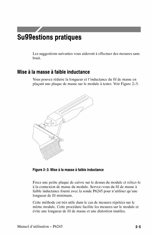
Vous pouvez réduire la longueur et l’inductance du fil de masse enplaçant une plaque de masse sur le module à tester. Voir Figure 2--3.
Figure 2- 3: Mise à la masse à faible inductance
Fixez une petite plaque de cuivre sur le dessus du module et reliez--leà la connexion de masse du module. Servez--vous du fil de masse àfaible inductance fourni avec la sonde P6245 pour n’utiliser qu’unelongueur de fil minimum.
Cette méthode est très utile dans le cas de mesures répétées sur lemême module. Cette procédure facilite les mesures sur le module etévite une longueur de fil de masse et une distortion inutiles.

Suggestions pratiques
2- 6 Manuel d’utilisation -- P6245
Mise à la masse avec l’adaptateur SureFoot™
Si vous ne pouvez pas utiliser la méthode de mise à la masse à faibleinductance recommandée ci--dessus, la sonde peut être mise à lamasse sur le module à tester à l’aide d’un adaptateur SureFoot.Reportez--vous à la Figure 2--4.
Figure 2- 4: Utilisation d’un adaptateur SureFoot pour mise à la masse
Placez un adaptateur SureFoot sur un fil de masse court et connec-tez--le directement à la prise de masse du module. Cette méthode estpréférable à l’utilisation de la prise de masse d’un circuit adjacentcar la connexion à la masse est la plus courte possible.

Suggestions pratiques
Manuel d’utilisation -- P6245 2- 7
Points de mesure avec embout de sonde
Vous pouvez souder l’embout de sonde amovible ou une brochecarrée de 0,025 pouce dans un circuit pour en faire un point demesure temporaire. Voir Figure 2--5.
Soudez l’embout sur un fil ou une broche à l’aide d’un fer à souderde faible puissance. Appuyez la tête de la sonde sur l’embout poureffectuer la mesure, puis retirez la tête quand vous avez fini.
Vous pouvez enlever l’embout de la sonde et le réutiliser : il suffit dele dessouder et de le ressouder sur un autre circuit.
Soudure
Figure 2- 5: Utilisation d’un embout de sonde comme point de mesure
NOTE. Il n’est pas recommandé d’utiliser des fils en métal durcomme points de mesure. Si le fil se cassait dans la prise de l’emboutde sonde, il pourrait s’avérer impossible de l’enlever et celaempêcherait l’utilisation d’autres embouts accessoires.

Suggestions pratiques
2- 8 Manuel d’utilisation -- P6245
Stabilisation de l’embout de sonde
La tête de la sonde P6245 possède une encoche de stabilisationacceptant des broches espacées de 0,100 pouce. Voir le schémadétaillé de la tête de sonde, page 1--3.
Lorsque vous appuyez la sonde sur une broche, une broche adjacentepeut s’insérer dans l’encoche de stabilisation de la sonde. Voir Figure2--6. Ceci évite de forcer inutilement sur l’embout de la sonde ou surles broches.
Encoche destabilisation
Figure 2- 6: Encoche de stabilisation inductance
L’adaptateur signal--masse repose alors sur la broche stabilisée sansrisque de bouger.

Caractéristiques techniques


Manuel d’utilisation -- P6245 3- 1
Caractéristiques techniques
Les caractéristiques techniques ci--dessous s’appliquent à la sondeP6245 lorsqu’elle est utilisée avec un oscilloscope TDS 684A.
Respectez un temps de chauffe de 20 minutes pour la sonde etl’oscilloscope avant de procéder aux mesures.
CAUTION. N’appliquez pas à la sonde des tensions dépassant leslimites de tension d’entrée non destructive. Vous pourriez endomma--ger la sonde ou le circuit testé.
Table 3- 1: Caractéristiques électriques garanties
Bande passante analogique (système) 1 GHz
Précision de l’atténuation du courant continu(sonde seulement)
10 pour 1 ±2%
Zéro de sortie �5 mV ou moins à la sortie de la sonde
�50 mV ou moins affiché à l’écran avecinterface TEKPROBE
Temps de montée (sonde seulement) 267 ps sur oscilloscope≥10 GHz
Caractéristiques techniques
3- 2 Manuel d’utilisation -- P6245
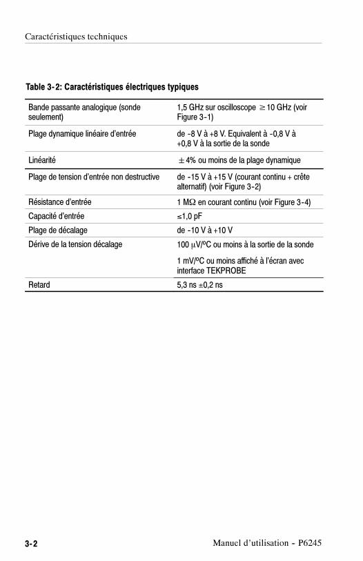
Table 3- 2: Caractéristiques électriques typiques
Bande passante analogique (sondeseulement)
1,5 GHz sur oscilloscope≥10 GHz (voirFigure 3--1)
Plage dynamique linéaire d’entrée de --8 V à +8 V. Equivalent à --0,8 V à+0,8 V à la sortie de la sonde
Linéarité �4% ou moins de la plage dynamique
Plage de tension d’entrée non destructive de --15 V à +15 V (courant continu + crêtealternatif) (voir Figure 3--2)
Résistance d’entrée 1 MΩ en courant continu (voir Figure 3--4)
Capacité d’entrée ≤1,0 pF
Plage de décalage de --10 V à +10 V
Dérive de la tension décalage 100 �V/oC ou moins à la sortie de la sonde
1 mV/oC ou moins affiché à l’écran avecinterface TEKPROBE
Retard 5,3 ns ±0,2 ns
Caractéristiques techniques
Manuel d’utilisation -- P6245 3- 3
0 dB
--1 dB
--2 dB
--3 dB
--4 dB
--5 dB
--6 dB
--7 dB
--8 dB
+1 dB
+2 dB
1 MHz 1 GHz100 MHz10 MHz
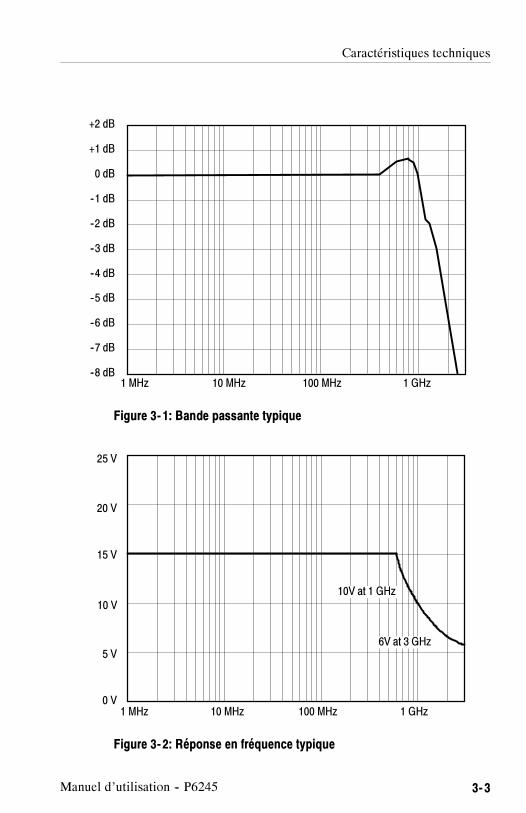
Figure 3- 1: Bande passante typique
25 V
20 V
15 V
1 MHz 10 MHz 100 MHz
5 V
0 V
10 V10V at 1 GHz
6V at 3 GHz
1 GHz
Figure 3- 2: Réponse en fréquence typique

Caractéristiques techniques
3- 4 Manuel d’utilisation -- P6245
--20 V 0 V--10 V 10 V 20 V
150 mV
100 mV
50 mV
--100 mV
0 mV
--50 mV
--150 mV
Erreurd’affichage
VIN
Figure 3- 3: Erreur de linéarité typique par rapport à la tension d’entrée
10 MΩ
1 MΩ
100 kΩ
10kΩ
1 kΩ
100Ω
10Ω
100 Hz 1 GHz100 kHz1 kHz 10 kHz 1 MHz 10 MHz 100 MHz
Figure 3- 4: Impédance d’entrée typique par rapport à la fréquence

Caractéristiques techniques
Manuel d’utilisation -- P6245 3- 5
20°
0°
--20°
--40°
100 Hz 1 GHz100 kHz1 kHz 10 kHz 1 MHz 10 MHz 100 MHz
--80°
--100°
--60°
Figure 3- 5: Phase typique par rapport à la fréquence

Caractéristiques techniques
3- 6 Manuel d’utilisation -- P6245
Table 3- 3: Caractéristiques physiques
Poids net 63,8 g
Longueur de câble 1,3 mètre
Table 3- 4: Caractéristiques d’environnement
Température de fonctionnement De 0o C à + 50o C.
Les conditions ambiantes sont définies par la normeTektronix Design Standard 062--2847--00 pour lematériel de classe 5.
Température hors fonctionnement De --40o C à + 71o C.
Les conditions ambiantes sont définies par la normeTektronix Design Standard 062--2847--00 pour lematériel de classe 5.
Humidité Les conditions ambiantes sont définies par la normeTektronix Design Standard 062--2847--00 pour lematériel de classe 5.
Vibrations et chocs du produitemballé
Le produit emballé répond aux exigences du<< Distribution Cycle 1 Assurance Level II >> pour lesproduits emballés de 0 à 9,1 kg. Le Test 2 pourempilement (compression) en entrepôt et véhicule estomis.
Norme Tektronix 062--2858--00, Rev. B, Classe 5.
Altitude maximale En fonctionnement : 4 570 mHors fonctionnement : 15 240 m

Deutsch


P62451,5 GHz 10X Activer Tastkopf
ZZZ
Benutzerhandbuch
xx
www.tektronix.com070-8995-05

Copyright © Tektronix. Alle Rechte vorbehalten. Lizensierte Software-Produktestellen Eigentum von Tektronix oder Tochterunternehmen bzw. Zuliefererndes Unternehmens dar und sind durch nationale Urheberrechtsgesetze undinternationale Vertragsbestimmungen geschützt.
Tektronix-Produkte sind durch erteilte und angemeldete Patente in den USA undanderen Ländern geschützt. Die Informationen in dieser Broschüre machenAngaben in allen früheren Unterlagen hinfällig. Änderungen der Spezifikationenund der Preisgestaltung vorbehalten.
TEKTRONIX und TEK sind eingetragene Marken der Tektronix, Inc.
Tektronix-KontaktinformationenTektronix, Inc.14200 SW Karl Braun DriveP.O. Box 500Beaverton, OR 97077USA
Informationen zu diesem Produkt und dessen Verkauf, zum Kundendienst sowiezum technischen Support:
In Nordamerika rufen Sie die folgende Nummer an: 1-800-833-9200.Unter www.tektronix.com finden Sie die Ansprechpartner in Ihrer Nähe.

Garantie
Tektronix garantiert, dass dieses Produkt für einen Zeitraum von einem (1) Jahr abVersanddatum keine Fehler in Material und Verarbeitung aufweist. Wenn ein Produktinnerhalb dieser Garantiezeit Fehler aufweist, steht es Tektronix frei, dieses fehlerhafteProdukt kostenlos zu reparieren oder einen Ersatz für dieses fehlerhafte Produkt zurVerfügung zu stellen. Von Tektronix für Garantiezwecke verwendete Teile, Module undErsatzprodukte können neu oder in ihrer Leistung neuwertig sein. Alle ersetzten Teile,Module und Produkte werden Eigentum von Tektronix.
Um mit dieser Garantie Kundendienst zu erhalten, muss der Kunde Tektronix über denFehler vor Ablauf der Garantiezeit informieren und geeignete Vorkehrungen für dieDurchführung des Kundendienstes treffen. Der Kunde ist für die Verpackung und denVersand des fehlerhaften Produkts an die Service-Stelle von Tektronix verantwortlich, dieVersandgebühren müssen im Voraus bezahlt sein. Tektronix übernimmt die Kosten derRücksendung des Produkts an den Kunden, wenn sich die Versandadresse innerhalb desLandes der Tektronix Service-Stelle befindet. Der Kunde übernimmt alle Versandkosten,Fracht- und Zollgebühren sowie sonstige Kosten für die Rücksendung des Produkts aneine andere Adresse.
Diese Garantie tritt nicht in Kraft, wenn Fehler, Versagen oder Schaden auf die falscheVerwendung oder unsachgemäße und falsche Wartung oder Pflege zurückzuführen sind.Tektronix muss keinen Kundendienst leisten, wenn a) ein Schaden behoben werden soll,der durch die Installation, Reparatur oder Wartung des Produkts von anderem Personal alsTektronix-Vertretern verursacht wurde; b) ein Schaden behoben werden soll, der auf dieunsachgemäße Verwendung oder den Anschluss an inkompatible Geräte zurückzuführenist; c) Schäden oder Fehler behoben werden sollen, die auf die Verwendung vonKomponenten zurückzuführen sind, die nicht von Tektronix stammen; oder d) wennein Produkt gewartet werden soll, an dem Änderungen vorgenommen wurden oder dasin andere Produkte integriert wurde, so dass dadurch die aufzuwendende Zeit für denKundendienst oder die Schwierigkeit der Produktwartung erhöht wird.
DIESE GARANTIE WIRD VON TEKTRONIX FÜR DAS PRODUKT ANSTELLEANDERER AUSDRÜCKLICHER ODER IMPLIZITER GARANTIEN GEGEBEN.TEKTRONIX UND SEINE HÄNDLER SCHLIESSEN AUSDRÜCKLICH ALLEGARANTIEN HINSICHTLICH DER HANDELSGÄNGIGKEIT UND DER EIGNUNGFÜR EINEN BESTIMMTEN ZWECK AUS. FÜR TEKTRONIX BESTEHT DIEEINZIGE UND AUSSCHLIESSLICHE VERPFLICHTUNG DIESER GARANTIEDARIN, FEHLERHAFTE PRODUKTE FÜR DEN KUNDEN ZU REPARIEREN ODERZU ERSETZEN. TEKTRONIX UND SEINE HÄNDLER ÜBERNEHMEN KEINERLEIHAFTUNG FÜR DIREKTE, INDIREKTE, BESONDERE UND FOLGESCHÄDEN,UNABHÄNGIG DAVON, OB TEKTRONIX ODER DER HÄNDLER VON DERMÖGLICHKEIT SOLCHER SCHÄDEN IM VORAUS UNTERRICHTET IST.
[W2 – 15AUG04]


P6245 Benutzerhandbuch i
Inhalt
Inbetriebnahme
Beschreibung des Geräts 1--1. . . . . . . . . . . . . . . . . . . . . . . . . . . . .Standardzubehör 1--1. . . . . . . . . . . . . . . . . . . . . . . . . . . . . . . . . . . .Kundendienst 1--2. . . . . . . . . . . . . . . . . . . . . . . . . . . . . . . . . . . . . . .
Eigenschaften und Zubehörteile 1--3. . . . . . . . . . . . . . . . . . . . . . .
Konfiguration 1--9. . . . . . . . . . . . . . . . . . . . . . . . . . . . . . . . . . . . . .Tastkopf--Offset 1--9. . . . . . . . . . . . . . . . . . . . . . . . . . . . . . . . . . . . .
Funktionstest 1--11. . . . . . . . . . . . . . . . . . . . . . . . . . . . . . . . . . . . . .
Grundlegendes zum Betrieb
Maximale zerstörungsfreie Eingangsspannung 2--1. . . . . . . . . . . . .Linearer Eingangsdynamikbereich 2--1. . . . . . . . . . . . . . . . . . . . . .Länge der Erdleitung 2--2. . . . . . . . . . . . . . . . . . . . . . . . . . . . . . . . .
Hilfreiche Hinweise 2--5. . . . . . . . . . . . . . . . . . . . . . . . . . . . . . . . .Niedriginduktionserdung 2--5. . . . . . . . . . . . . . . . . . . . . . . . . . . . . .SureFoot™--Erdung 2--6. . . . . . . . . . . . . . . . . . . . . . . . . . . . . . . . . .Prüfpunkte für die Tastkopfspitze 2--7. . . . . . . . . . . . . . . . . . . . . . .Stabilisierung der Tastkopfspitze 2--8. . . . . . . . . . . . . . . . . . . . . . .
Spezifikationen

Inhalt
ii P6245 Benutzerhandbuch
Abbildungen
Figure 1--1: Dynamische und Offsetbegrenzungen 1--10. . . . . . . . .Figure 1--2: Anschlüsse zum Funktionstest des Tastkopfes 1--11. . .
Figure 2--1: Verzerrung des Signals durch Längeder Erdleitung 2--2. . . . . . . . . . . . . . . . . . . . . . . . . . . . . . . . . . . .
Figure 2--2: Äquivalentstromkreis für Erdleiter 2--3. . . . . . . . . . . .Figure 2--3: Niedriginduktionserdung 2--5. . . . . . . . . . . . . . . . . . . .Figure 2--4: Verwendung eines SureFoot--Adapters zur Erdung 2--6Figure 2--5: Verwendung einer Tastkopfspitze als Prüfpunkt 2--7. .Figure 2--6: Stabilisierungskerbe an der Tastkopfspitze 2--8. . . . . .
Figure 3--1: Typische Bandbreite 3--3. . . . . . . . . . . . . . . . . . . . . . . .Figure 3--2: Typische Spannungsabnahme vs. Frequenz 3--3. . . . . .Figure 3--3: Typischer Linearitätsfehler vs. VEingang 3--4. . . . . . .Figure 3--4: Typische Eingangsimpedanz vs. Frequenz 3--4. . . . . .Figure 3--5: Typische Phase vs. Frequenz 3--5. . . . . . . . . . . . . . . . .

P6245 Benutzerhandbuch iii
Zusammenfassende Sicherheitshinweise
Beachten Sie die nachstehenden Sicherheitsvorkehrungen, umVerletzungen zu vermeiden und Schäden an diesem Produkt und andaran angeschlossenen Produkten zu verhindern.
Wartungsarbeiten sind ausschließlich von qualifiziertem Personaldurchzuführen.
Verletzungsverhütung
Elektrische Überbelastung vermeiden
Zur Vermeidung von Feuergefahr oder eines elektrischen Schlagsdarf niemals eine Spannung an einen Ein-- oder Ausgangspunktangelegt werden, die den für jene Punkte vorgeschriebenen Bereichübersteigt.
Nicht ohne Abdeckungen betreiben
Zur Vermeidung von Feuergefahr oder eines elektrischen Schlagsdarf dieses Produkt niemals ohne seine Abdeckungen oder dieFrontplatte betrieben werden.
Kein Betreiben in feuchter Umgebung
Um Stromschläge zu vermeiden, sollte dieses Gerät nicht in feuchterUmgebung betrieben werden.
Nicht in explosiver Umgebung betreiben
Zur Vermeidung von Verletzungen und Feuergefahr darf diesesProdukt nicht in explosionsgefährdeter Umgebung betrieben werden.

Zusammenfassende Sicherheitshinweise
iv P6245 Benutzerhandbuch
Schadensverhütung
Nicht bei Verdacht auf Geräteschaden betreiben
Bei Verdacht auf Schaden lassen Sie das Produkt von qualifiziertemWartungspersonal überprüfen.
Vor Flüssigkeiten schützen
Säubern Sie den Tastkopf nur mit einem feuchten Lappen. BeachtenSie die Reinigungshinweise.
Symbole und Bezeichnungen
Bezeichnungen in diesem Handbuch:
Diese Bezeichnungen können im Handbuch vorkommen:
WARNING. bezeichnet Bedingungen oder Handlungsweisen, die
Verletzungen oder den Tod zur Folge haben könnten.
CAUTION. bezeichnet Bedingungen oder Handlungsweisen, die
Sachschäden an diesem Produkt oder an anderem Eigentum zur
Folge haben könnten.

P6245 Benutzerhandbuch v
Aufbau des Handbuchs
Informationen für den Benutzer
In diesem Abschnitt sind Informationen enthalten, die zur Installa-tion und zum Gebrauch des P6245 erforderlich sind.
� Inbetriebnahme
In diesem Abschnitt sind die Gerätebeschreibung, die Beschreibungder Zubehörteile, die Konfiguration des Tastkopfes sowie Informatio-nen zur Überprüfung des ordnungsgemäßen Funktionierens desTastkopfes enthalten.
� Grundlegendes zum Betrieb
In diesem Abschnitt sind grundlegende Informationen und Betriebs--hinweise zum Erreichen einer optimalen Leistung des Tastkopfesenthalten.
� Spezifikationen
Informationen zur Wartung (nur in englischer Sprachevorhanden)
In diesem Abschnitt sind Informationen enthalten, die zur Wartungund Instandhaltung des P6245 erforderlich sind.
� Betriebstheorie
� Leistungsnachweis
� Anpassungen
� Wartung
� Fehlersuche
Ersatzteilliste (nur in englischer Sprache vorhanden)

Aufbau des Handbuchs
vi P6245 Benutzerhandbuch

Inbetriebnahme


P6245 Benutzerhandbuch 1- 1
Beschreibung des Geräts
Beim Gerät P6245 von Tektronix handelt es sich um einen 1,5 GHz(gilt nur für Tastkopf), 10X aktiven FET--Tastkopf mit weniger als 1pF Eingangskapazität. Die niedrige Eingangskapazität des P6245sowie ein hoher Eingangswiderstand reduzieren die Schaltkreisbe--lastung über eine weite Bandbreite auf ein Mindestmaß. Das schmaleProfil und ein Kopf von geringer Masse machen manuelle Untersu-chungen von gedrängten Schaltkreisen leicht und schnell. Zu-behörteile wie Spitzen und Adapter ermöglichen den Einsatz desP6245 für eine vielfältige Schaltkreisarchitektur.
Der P6245 wird über eine TEKPROBE--Schnittstelle zwischen derKompensationsbox des Tastkopfes und dem Oszilloskop mit Stromversorgt. Der P6245 kann auch mit Nicht--TEKPROBE--Oszillosko-pen und Geräten verwendet werden, wenn die Stromversorgung desTastkopfes über das optionelle Tastkopf--StromversorgungsgerätTektronix 1103 erfolgt.
Wenn Sie sich mit den weiteren Anwendungsmöglichkeiten desTastkopfes voll vertraut machen wollen, lesen Sie bitte dieAbschnitte Inbetriebnahme sowie Grundlegendes zum Betrieb indiesem Benutzerhandbuch.
Standardzubehör
Der P6245 wird mit folgenden Standardzubehörteilen geliefert:
� Standard--Tastkopfspitzen
� Mikroschaltungsprüfleiter SMT--KlipChip™
� Y--förmiger Adapter
� Rechtwinkeladapter
� Signal--Erdadapter
� Erdleiter mit einer Länge von 7,6 cm bzw. 15 cm
� Niedriginduktionserdleiter
� Markierungsringe

Beschreibung des Geräts
1- 2 P6245 Benutzerhandbuch
� Benutzerhandbuch
Informationen über Teilenummern für Standard-- und optionelleZubehörteile finden Sie im Abschnitt Ersatzteile in diesemHandbuch.
Kundendienst
Damit Sie die Leistung Ihres Tastkopfes optimal nutzen können,bietet Tektronix folgenden Kundendienst an:
Technische Unterstützung
Falls Sie sich außerhalb der USA oder Kanadas befinden, wendenSie sich an Ihre Tektronix--Kundendienstzentrale.
Reparaturdienst
Falls an Ihrem Gerät eine Reparatur auszuführen ist, die Sie nicht mitHilfe dieses Handbuchs erledigen können, wenden Sie sich an IhreTektronix--Kundendienstzentrale.
Verkaufsdienst
Falls Sie sich außerhalb der USA oder Kanadas befinden, wendenSie sich an Ihre Tektronix--Kundendienstzentrale.

P6245 Benutzerhandbuch 1- 3
Eigenschaften und Zubehörteile
Der P6245 verfügt über verschiedene Eigenschaften und Zu-behörteile, die Untersuchungen und Messungen erleichtern sollen. Imfolgenden werden Sie mit den einzelnen Teilen und deren Anwen-dungsmöglichkeiten vertraut gemacht.
Stecker an derTastkopfspitze
Erdstecker
Stabilisierungskerbe
Tastkopf. Die Gestaltung des Tastkopfes solleine problemlose und leistungsfähige Anwendungermöglichen. Seine geringe Größe macht dieAnwendung auch bei wenig verfügbarem Platzmöglich.
Der Stecker an der Tastkopfspitze ist so gestaltet,daß 0,025--Inch--Stifte direkt angepaßt werdenkönnen. Der Erdstecker ist mit einem kurzenErdpfad für High--Fidelity--Erdverbindungenausgestattet.
Die Stabilisierungskerbe gestattet es, benach-barte Stifte zur Reduzierung der Belastungen vonTastkopf und Stiften zu verwenden. WeitereInformationen finden Sie auf den Seiten 1--7sowie 2--8.
TEKPROBE™- Schnittstelle. Die TEK-PROBE--Schnittstelle wird als Kommunikations--pfad zwischen Tastkopf und Oszilloskopverwendet. Kontaktstifte ermöglichen dieÜbertragung von Strom, Signalen, Offset sowievon für den Tastkopf charakteristischen Daten.Weitere Informationen finden Sie auf derSeite 4--2.
Falls Ihr Oszilloskop die TEKPROBE--Schnitt-stelle nicht unterstützt, können Sie auch daswahlweise Tastkopf--StromversorgungsgerätTektronix 1103 als effektive Schnittstelleverwenden. Zwecks weiterer Informationenwenden Sie sich an Ihre Tektronix--Vertretung.

Eigenschaften und Zubehörteile
1- 4 P6245 Benutzerhandbuch
Stecktastkopfspitze
Stecktastkopfspitze. Verwenden Sie dieStecktastkopfspitze für allgemeine manuelleUntersuchungen. Die Spitze kann auch alszeitweiliger Prüfpunkt verwendet werden. WeitereInformationen finden Sie auf Seite 2--7.
Die Stecktastkopfspitze kann auch in Verbindungmit den anderen Leitern und Adaptern verwendetwerden.
Installation der Stecktastkopfspitze. ZumAnbringen der Stecktastkopfspitze wird die Spitzean den Tastkopfspitzenstecker angepaßt unddanach fest angedrückt, bis sie einrastet. BeideSpitzenenden können verwendet werden.Wenden Sie keine Gewalt an. Achten Sie auchdarauf, daß Sie sich mit der scharfen Tastkopf-spitze nicht stechen. Zum Entfernen der Spitzeverwenden Sie eine kleine Zange, mit der Sie dieSpitze langsam herausziehen.

Eigenschaften und Zubehörteile
P6245 Benutzerhandbuch 1- 5
Rechtwinkel--adapter
Rechtwinkeladapter. Verwenden Sie denRechtwinkeladapter für Niedrigprofiluntersuchun-gen von Vierkantstiften mit einem Durchmesservon 0,025 Inch.
Durch den Rechtwinkeladapter kann der P6245flach auf der Schaltplatte liegen, wodurchUntersuchungen in vertikalen Schaltkreisen wiez.B. in Computer-- oder DFV--Rückwandplatinenoder in sehr engen Bereichen wie z.B. zwischenEinsteckkarten ermöglicht werden.
Der Rechtwinkeladapter kann entweder direkt mitdem Tastkopf oder zusammen mit dem Adapterfür den Y--Leiter bzw. den Erdleitern verwendetwerden.
Der Rechtwinkeladapter wird wie die Stecktast-kopfspitze angebracht; er kann leicht per Handentfernt werden.
Y--förmigerAdapter
Y- förmiger Adapter. Verwenden Sie denY--förmigen Adapter zur notwendigen Erweiter-ung der Reichweite des Tastkopfes und derErdung. Der Y--förmige Adapter nimmt jedeTastkopfspitze und jeden Adapter auf. Er kanndirekt auf die 0,025--Inch--Stifte gedrückt werden.
Bei der Auswahl der Erdverbindung ist zubeachten, daß der Erdweg so kurz wie möglichist. Weitere Informationen finden Sie auf Seite2--1.
Zum Anbringen des Y--förmigen Adapters werdendie Leiterstifte langsam in die Tastkopfspitze unddie Erdstecker gedrückt. Es wird empfohlen, denschwarzen Leiter zur Erdung zu verwenden.

Eigenschaften und Zubehörteile
1- 6 P6245 Benutzerhandbuch
Erdleiter mit einer Länge von 7,6 cm bzw.15 cm. Verwenden Sie die Erdleiter mit einerLänge von 7,6 cm bzw. 15 cm für allgemeineUntersuchungen. Die mit Steckern versehenenEnden der Leiter können mit jeder Tastkopfspitzeund jedem Adapter verbunden oder an die0,025--Inch--Stifte angepaßt werden.
Zum Anbringen der Erdleiter drücken und drehenSie die Leiterstiftsteckverbindung in denErdstecker am Tastkopf. Der Leiter kann durchHerausziehen per Hand wieder entfernt werden.
Bei der Auswahl der Erdverbindung ist zubeachten, daß der Erdweg so kurz wie möglichist. Weitere Informationen finden Sie aufSeite 2--1.
Niedriginduktionserdleiter. Verwenden Sieden Niedriginduktionserdleiter, um die Induktionder Erdleiter bedeutend zu verringern. Da derErdleiter einfach Masse berührt, kann man denTastkopf leicht an verschiedene Punkte auf demzu prüfenden Gerät bringen.
Zum Anbringen drücken Sie den Erdleiter in denErdstecker am Tastkopf.
Bei der Auswahl der Erdverbindung ist zubeachten, daß der Erdweg so kurz wie möglichist. Weitere Informationen finden Sie aufSeite 2--1.

Eigenschaften und Zubehörteile
P6245 Benutzerhandbuch 1- 7
Signal--Erdadapter
FlexLeadAdapter
Signal- Erdadapter. Der Signal--Erdadapter istzur Verwendung mit Signal--/Erdpaaren auf0,100--Verteilerstiften (wie z.B. FlexLead™--Adapter) besonders geeignet.
Zum Anbringen des Signal--Erdadapters drückenSie ihn langsam in den Erdstecker am Tastkopf.
Wenn möglich, verwenden Sie die Stabilisier--ungskerbe. Weitere Details finden Sie auf Seite2--8.
KlipChip--Klemme
Y--förmigerAdapter
SMT-KlipChip™- Klemme. Verwenden SieSMT--KlipChip--Prüfklemmen, wenn Sie leichtzerbrechliche und enge Schaltkreisanordnungenerreichen wollen.
Die KlipChip--Prüfklemmen können mit demY--Leiter oder Erdleitern von 7,6 cm bzw. 15 cmLänge verbunden werden. Drücken Sie einfachden Leiterstecker in den KlipChip--Griff.
Die KlipChip--Klemme kann leicht gedrehtwerden, so daß eine bessere Tastkopfausrichtungermöglicht wird. Um die Belastung zu verringernsowie ein flacheres Profil auf zu prüfenden Teilenbereitzustellen, kann der flexible Schaft derKlipChip--Klemmen in einem Winkel bis zu35 Grad gebogen werden.
Farbmarkie--rungsbänder
Farbmarkierungsbänder. Bringen Siepaarweise gleiche Farbmarkierungsbänder amKabel, welches sich am Kopf befindet, sowie anden Kompensationsboxen jedes einzelnenTastkopfes an. Die Farbmarkierungsbänderermöglichen einen schnellen Überblick darüber,welcher Tastkopf mit welchem Gerätekanalverbunden ist.

Eigenschaften und Zubehörteile
1- 8 P6245 Benutzerhandbuch
SureFoot™- Tastkopfspitze (wahlweise).Bei der SureFoot--Spitze handelt es sich um eineeingebaute Tastkopfspitze und Miniaturführung,die fehlerfreie Untersuchungen von feingliedrigenSMD--Gehäusen ermöglicht. Die SureFoot--Adapter werden wie die Stecktastkopfspitzenangebracht. Sie können mit jedem Leiterverwendet werden, der mit einem Steckerausgerüstet ist.
Die gelbe 0,050--Inch--SureFoot--Spitze ist mit50--Milli--Inch--JEDEC--Gehäusen wie SOIC,PLCC, CLCC usw. kompatibel.
Die blaue 0,025--Inch--SureFoot--Spitze ist mit0,65--mm--JEDEC-- und EIAJ--Gehäusenkompatibel.
Die rote 0,5--mm--SureFoot--Spitze ist mitEIAJ--Gehäusen kompatibel.
P6245 Benutzerhandbuch 1- 9
Konfiguration
Der P6245 liefert dem Oszilloskop die Typnummer des Tastkopfes,die Seriennummer sowie den Abschwächungsfaktor. Beim Anschlußan ein TEKPROBE--Oszilloskop werden die Anzeigedatenentsprechend dem Tastkopf--Abschwächungsfaktor korrigiert, derGeräteeingang wird auf 50 Ω und die Kopplung auf Gleichstromgestellt.
CAUTION. Installieren Sie den P6245 nicht auf einem Nicht--TEK-PROBE--Anschluß, da dadurch Schaden am Tastkopf und Anschluß
entstehen kann. Falls Ihr Oszilloskop die TEKPROBE--Schnittstelle
nicht unterstützt, verwenden Sie das wahlweise Tastkopf--Stromver-
sorgungsgerät Tektronix 1103.
Falls der P6245 mit Tastkopf--Stromversorgungsgerät Tektronix 1103verwendet wird, vergewissern Sie sich, daß ein 50--Ω--Anschluß am
Oszilloskop zur Verfügung steht. Des weiteren stellen Sie die
Kanalkopplung am Oszilloskop auf Gleichstrom.
Die Tastkopf--Offsetsteuerung erfolgt vom Oszilloskop aus. Falls dasverwendete Oszilloskop die TEKPROBE--Schnittstelle nichtunterstützt, kann die Offsetsteuerung am StromversorgungsgerätTektronix 1103 verwendet werden.
Tastkopf-Offset
Der Tastkopf--Offset ist anpaßbar, damit eine Funktionsfähigkeitinnerhalb des linearen Bereichs des Tastkopfes gewährleistet ist.Wenn mit dem Offset Gleichstromsignalkomponenten gelöschtwerden, wird eine maximale Tastkopfleistung ermöglicht. SieheAbbildung 1--1 auf Seite 1--10.
NOTE. Spezielle Anleitungen zur Funktionsfähigkeit und Offsetsteuer-
ung finden Sie im Handbuch für das Oszilloskop.

Konfiguration
1- 10 P6245 Benutzerhandbuch
Einstellen des Tastkopf--Offset:
1. Kopplung des Oszilloskops auf Masse stellen.
2. Mit der vertikalen Positionssteuerung eine Nullreferenz auf derOszilloskopanzeige einstellen.
3. Kopplung des Oszilloskops auf Gleichstrom und 5 V/Div. stellen.
4. Tastkopf am Schaltkreis anbringen.
5. Tastkopf--Offset so justieren, daß die Meßkurve mit derNullreferenz des Oszilloskops übereinstimmt.
6. Volt/Div.--Einstellung auf den gewünschten Bereich verändernund den Offset so einstellen, daß die Meßkurve auf derNullreferenzstufe bleibt.
NOTE. Der P6245 hat einen Offsetbereich von � 10 V. Der lineare
Arbeitsbereich beträgt � 8 V. Siehe Abbildung 1--1. WeitereInformationen finden Sie auf Seite 2--1.
Wenn am TEKPROBE--Oszilloskop Cursors verwendet werden, hat
die Nullreferenz den Wert der Offsetspannung des Tastkopfes.
0 V
+15 V
--15 V
+8 V
--8 V
+10 V
--10 V
+10 V
--10 V
Nichtbetriebsbereich (+15 V Maximale zerstörungsfreie Eingangsspannung)
Maximale Amplitude desWechselstromsignals
MaximalerOffsetbereich
Nichtbetriebsbereich (--15 V Maximale zerstörungsfreie Eingangsspannung)
Figure 1- 1: Dynamische und Offsetbegrenzungen
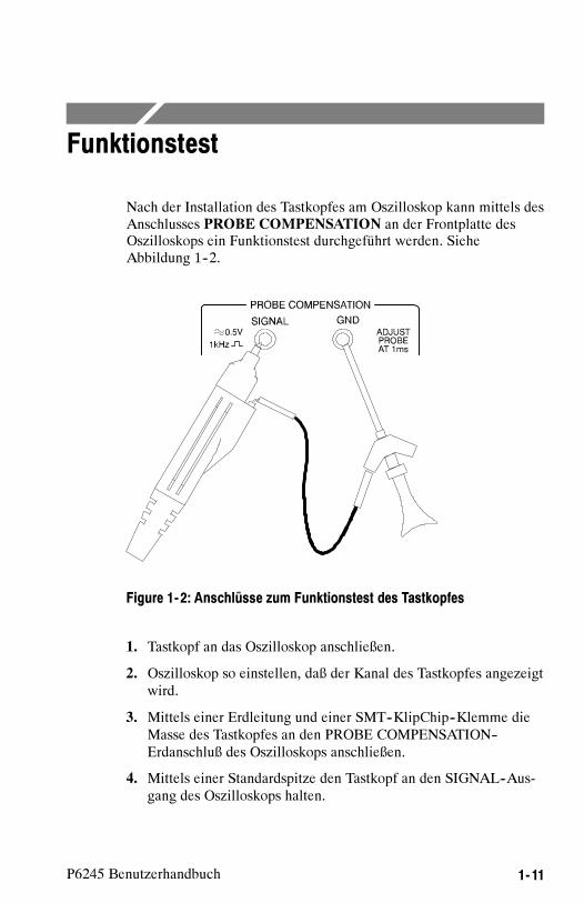
P6245 Benutzerhandbuch 1- 11
Funktionstest
Nach der Installation des Tastkopfes am Oszilloskop kann mittels desAnschlusses PROBE COMPENSATION an der Frontplatte desOszilloskops ein Funktionstest durchgeführt werden. SieheAbbildung 1--2.
Figure 1- 2: Anschlüsse zum Funktionstest des Tastkopfes
1. Tastkopf an das Oszilloskop anschließen.
2. Oszilloskop so einstellen, daß der Kanal des Tastkopfes angezeigtwird.
3. Mittels einer Erdleitung und einer SMT--KlipChip--Klemme dieMasse des Tastkopfes an den PROBE COMPENSATION--Erdanschluß des Oszilloskops anschließen.
4. Mittels einer Standardspitze den Tastkopf an den SIGNAL--Aus-gang des Oszilloskops halten.

Funktionstest
1- 12 P6245 Benutzerhandbuch
5. Zur Anzeige des Kalibrationssignals AUTOSET drücken (oderOszilloskop justieren).
NOTE. Falls Ihr Gerät Kalibrationsroutinen des Tastkopfesunterstützt, führen Sie diese jetzt aus.
6. Tastkopf vom SIGNAL--Ausgang entfernen und Tastkopfspitzeerden. (KlipChip--Klemme an die Tastkopfspitze anschließen.)
7. Bei einem auf 0,0 gestellten Tastkopf--Offset müßte dieOszilloskopanzeige jetzt auf Erdreferenz stehen.
8. Volt/Div. des Oszilloskops auf 5 V stellen.
9. Tastkopf--Offset justieren. Das angezeigte Signal sollte zwischenca. + 10 und -- 10 V variieren. (Ein Offset von + 10 V zeigt anIhrem Gerät eine Stufe von -- 10 V an.)
NOTE. Falls kein Signal angezeigt wird, vergewissern Sie sich, daß
die vertikale Kopplung auf Gleichstrom gestellt ist.
Falls die Offsetanpassung keine Wirkung zeigt, stellen Sie dievertikale Kopplung auf Gleichstrom.
Falls Sie das Tastkopf--Stromversorgungsgerät Tektronix 1103
verwenden und das Signal verzerrt ist, vergewissern Sie sich, daß der
Eingangswiderstand des Oszilloskops 50 Ω beträgt.
Falls der Funktionstest für den Tastkopf nicht erfolgreich verläuft,informieren Sie sich im Abschnitt Fehlersuche in diesem Handbuchüber mögliche Ursachen.

Grundlegendes zum Betrieb

P6245 Benutzerhandbuch 2- 1
Grundlegendes zum Betrieb
Um eine optimale Leistung Ihres Tastkopfes P6245 zu erreichen,folgen Sie den nachstehenden Bedienungsrichtlinien.
Maximale zerstörungsfreie Eingangsspannung
Der P6245 ist elektrisch gegen statische Spannung geschützt.Dennoch kann es durch Anlegen von Spannungen über denvorgegebenen Werten zur Zerstörung der Verstärker an derTastkopfspitze kommen. Informieren Sie sich im AbschnittSpezifikationen in diesem Handbuch über maximale Betriebsspan-nung und Frequenzunterlastung.
Linearer Eingangsdynamikbereich
Der vom P6245 verwendete Verstärker am vorderen Tastkopfendehat einen begrenzten linearen Arbeitsbereich. Damit der Eingangsli-nearitätsfehler niedriger als 4 % bleibt, muß die Signaleingangsspan-nung auf � 8 V (einschließlich jedes Gleichstromoffsets) begrenztwerden.
Verwenden Sie die Gleichstromoffsetanpassung, damit der Tastkopfinnerhalb seines Dynamikbereichs verbleibt. Der Nennbereich derOffsetanpassung des P6245 beträgt � 10 V Gleichstrom. ZumBeispiel: Zum Versetzen von + 5 V Gleichstrom in einem Stromkreisstellt man den Offset auf + 5 V.
Länge der Erdleitung
Zur Untersuchung eines Schaltkreises sollte immer eine Erdleitungverwendet werden, die zwischen Tastkopf und Schaltkreiserdung sokurz wie möglich ist.
Die Serieninduktion, die durch die Tastkopfspitze und die Erdleitunghinzukommt, kann zu einem Resonanzkreis führen, der parasitäres
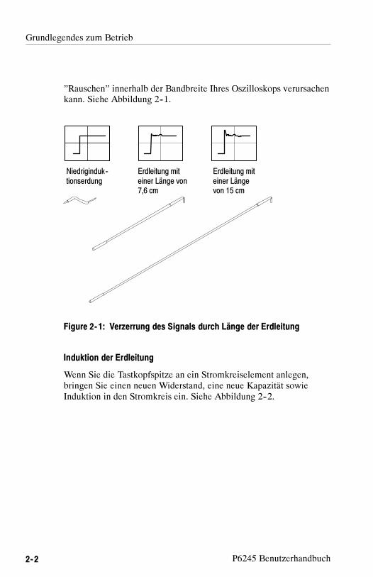
Grundlegendes zum Betrieb
2- 2 P6245 Benutzerhandbuch
”Rauschen” innerhalb der Bandbreite Ihres Oszilloskops verursachenkann. Siehe Abbildung 2--1.
Niedriginduk--tionserdung
Erdleitung miteiner Länge von7,6 cm
Erdleitung miteiner Längevon 15 cm
Figure 2- 1: Verzerrung des Signals durch Länge der Erdleitung
Induktion der Erdleitung
Wenn Sie die Tastkopfspitze an ein Stromkreiselement anlegen,bringen Sie einen neuen Widerstand, eine neue Kapazität sowieInduktion in den Stromkreis ein. Siehe Abbildung 2--2.

Grundlegendes zum Betrieb
P6245 Benutzerhandbuch 2- 3
RQuelle
VQuelleTastkopf:CEingang 1 pF
Tastkopf:REingang 1 MΩ
LEl (Erdleitung)
Figure 2- 2: Äquivalentstromkreis für Erdleiter
Rausch-- und Anstiegszeitfehler können abgedeckt werden, wennsich die Frequenzkomponenten des Signals außerhalb der Bandbreitedes Oszilloskops befindet.
Wenn Sie die Selbstinduktion (L) und Kapazität (C) Ihres Tastkopfesund der Erdleitung kennen, können Sie bestimmen, ob Erdleitungsef-fekte möglicherweise ein Problem für Ihren Anwendungsbereichdarstellen. Berechnen Sie die ungefähre Resonanzfrequenz (f0), beider dieser parasitäre Stromkreis in Resonanz kommen wird, nach derfolgenden Formel:
f0 =1
2π LC�
Aus der Gleichung wird ersichtlich, daß durch Reduzierung derErdleitungsinduktion die Resonanzfrequenz steigt. Falls IhreMessungen durch Rauschen beeinflußt werden, muß Ihr Ziel darinbestehen, die Induktion des Erdpfades soweit zu reduzieren, bis diesich ergebende Resonanzfrequenz weit höher ist als die FrequenzIhrer Messungen.
Die Beschreibung von Erdkontakten mit niedriger Induktion imAbschnitt Zubehörteile kann bei der Reduzierung der Auswirkungender Erdleitungsinduktion auf Ihre Messungen hilfreich sein.

Grundlegendes zum Betrieb
2- 4 P6245 Benutzerhandbuch

P6245 Benutzerhandbuch 2- 5
Hilfreiche Hinweise
Befolgen Sie die nachstehenden Hinweise, um Ihre Untersuchungeneinfacher und rauschfrei zu gestalten.
Niedriginduktionserdung
Sie können Erdleiterlänge und --induktion verringern, wenn Sie eineErdfläche direkt auf das zu untersuchende Gehäuse legen. SieheAbbildung 2--3.
Figure 2- 3: Niedriginduktionserdung
Bringen Sie ein kleines Stück Kupferblech auf dem Gehäuse an, undverbinden Sie es mit dem Erdanschluß des Gehäuses. Verwenden Siedie mit dem P6245 gelieferte Niedriginduktionserdleitung, um dieErdleiterlänge so kurz wie möglich zu halten.
Diese Methode erweist sich als besonders nützlich, wenn mehrereMessungen am selben Gehäuse ausgeführt werden. Durch Verwen-

Hilfreiche Hinweise
2- 6 P6245 Benutzerhandbuch
dung einer Erdfläche auf dem Gehäuse wird die Untersuchungeinfacher, und es werden unnötige Erdleiterlängen und Verzerrungenvermieden.
SureFoot™-Erdung
Falls die vorstehend empfohlene Methode zur Niedriginduktionser-dung nicht angewendet werden kann, kann der Tastkopf mittelsSureFoot--Adapter auf dem zu prüfenden Gehäuse geerdet werden.Siehe Abbildung 2--4.
Figure 2- 4: Verwendung eines SureFoot-Adapters zur Erdung
Verwenden Sie einen SureFoot--Adapter am Ende eines kurzenErdleiters zur Direktverbindung mit einer Gehäuseerdung. DieseMethode wird der Verwendung einer benachbarten Schaltkreiserdungvorgezogen, weil sie den kürzestmöglichen Erdpfad gestattet.

Hilfreiche Hinweise
P6245 Benutzerhandbuch 2- 7
Prüfpunkte für die Tastkopfspitze
Die Stecktastkopfspitze oder ein 0,025--Vierkantstift kann in einenSchaltkreis gelötet werden, der als zeitweiliger Prüfpunkt verwendetwerden soll. Vergleiche Abbildung 2--5.
Mit einem Niederleistungslötkolben löten Sie die Spitze auf einenLeiter oder Stift. Wenn Sie eine Messung vornehmen wollen, pressenSie den Tastkopf auf die Spitze; wenn Sie fertig sind, ziehen Sie denTastkopf wieder ab.
Die Tastkopfspitze kann entfernt und wiederverwendet werden, wennsie zunächst vom Schaltkreis abgelötet und später an einen anderenSchaltkreis angelötet wird.
Lötmittel
Figure 2- 5: Verwendung einer Tastkopfspitze als Prüfpunkt
NOTE. Stücke aus Vollkernkupferdraht werden nicht als Prüfpunkte
empfohlen. Wenn der Draht im Stecker der Tastkopfspitze abbricht,
kann es entweder unmöglich werden, ihn zu entfernen, oder andere
Zubehörspitzen können blockiert werden.

Hilfreiche Hinweise
2- 8 P6245 Benutzerhandbuch
Stabilisierung der Tastkopfspitze
Der P6245--Tastkopf verfügt über eine Stabilisierungskerbe, die zumGebrauch mit Verteilerstiften im Abstand von 0,100 Inch vorgesehenist. Siehe detaillierte Darstellung des Tastkopfes auf Seite 1--3.
Wenn der Tastkopf auf einen Verteilerstift gepreßt wird, kann einbenachbarter Stift in die Stabilisierungskerbe eingesetzt werden.Siehe Abbildung 2--6. Dadurch wird vermieden, daß unnötige Kraftdirekt auf die Tastkopfspitze oder die Stifte angewendet wird.
Stabilisierungskerbe
Figure 2- 6: Stabilisierungskerbe an der Tastkopfspitze
Der Signal--Erdadapter ruht dann auf dem stabilisierten Stift, ohnedie Gefahr des Verrutschens.

Spezifikationen

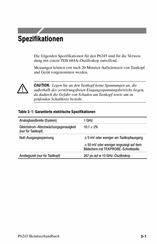
3- 1P6245 Benutzerhandbuch
Spezifikationen
Die folgenden Spezifikationen für den P6245 sind für die Verwen-dung mit einem TDS 684A--Oszilloskop zutreffend.
Messungen können erst nach 20 Minuten Aufwärmzeit von Tastkopfund Gerät vorgenommen werden.
CAUTION. Legen Sie an den Tastkopf keine Spannungen an, die
außerhalb des zerstörungsfreien Eingangsspannungsbereichs liegen,
da dadurch die Gefahr von Schaden am Tastkopf sowie am zuprüfenden Schaltkreis besteht.
Table 3- 1: Garantierte elektrische Spezifikationen
Analogbandbreite (System) 1 GHz
Gleichstrom--Abschwächungsgenauigkeit(nur für Tastkopf)
10:1 ± 2%
Null--Ausgangsspannung �5 mV oder weniger am Tastkopfausgang
�50 mV oder weniger angezeigt auf demBildschirm mit TEKPROBE--Schnittstelle
Anstiegszeit (nur für Tastkopf) 267 ps auf w 10 GHz--Oszilloskop

Spezifikationen
3- 2 P6245 Benutzerhandbuch
Table 3- 2: Typische elektrische Eigenschaften
Analogbandbreite (nur für Tastkopf) 1,5 GHz auf≥ 10 GHz--Oszilloskop (SieheAbbildung 3--1.)
Linearer Eingangsdynamikbereich --8 V bis +8 V. (Entspricht --0,8 V bis +0,8 Vam Tastkopfausgang.)
Linearität �4% oder weniger des Dynamikbereichs
Zerstörungsfreier Eingangsspannungs--bereich
--15 V bis +15 V (Gleichstrom und Wechsel-stromspitze) (Siehe Abbildung 3--2.)
Eingangswiderstand 1 MΩ bei Gleichstrom. (Siehe Abbildung3--4.)
Eingangskapazität ≤1,0 pF
Offsetbereich --10 V bis +10 V
Gleichstrom--Offsetdrift 100 �V/oC oder weniger am Tastkopfaus-gang
1 mV/oC oder weniger angezeigt auf demBildschirm mit TEKPROBE--Schnittstelle
Verzögerungszeit 5,3 ns ±0,2 ns

Spezifikationen
3- 3P6245 Benutzerhandbuch
0 dB
--1 dB
--2 dB
--3 dB
--4 dB
--5 dB
--6 dB
--7 dB
--8 dB
+1 dB
+2 dB
1 MHz 1 GHz100 MHz10 MHz
Figure 3- 1: Typische Bandbreite
25 V
20 V
15 V
1 MHz 10 MHz 100 MHz
5 V
0 V
10 V
10V at 1 GHz
6V at 3 GHz
1 GHz
Figure 3- 2: Typische Spannungsabnahme vs. Frequenz

Spezifikationen
3- 4 P6245 Benutzerhandbuch
--20 V 0 V--10 V 10 V 20 V
150 mV
100 mV
50 mV
--100 mV
0 mV
--50 mV
--150 mV
VEingang
Anzeigefehler
Figure 3- 3: Typischer Linearitätsfehler vs. VEingang
10 MΩ
1 MΩ
100 kΩ
10kΩ
1 kΩ
100Ω
10Ω
100 Hz 1 GHz100 kHz1 kHz 10 kHz 1 MHz 10 MHz 100 MHz
Figure 3- 4: Typische Eingangsimpedanz vs. Frequenz

Spezifikationen
3- 5P6245 Benutzerhandbuch
20°
0°
--20°
--40°
100 Hz 1 GHz100 kHz1 kHz 10 kHz 1 MHz 10 MHz 100 MHz
--80°
--100°
--60°
Figure 3- 5: Typische Phase vs. Frequenz

Spezifikationen
3- 6 P6245 Benutzerhandbuch
Table 3- 3: Physische Eigenschaften
Nettogewicht 63,8 gr
Kabellänge 1,3 meter
Table 3- 4: Umgebungseigenschaften
Betriebstemperatur 0°C bis +50°C.
Die Umgebungsbelastung wird nach Tektronix DesignStandard 062--2847--00 für Zubehörteile der Klasse 5bestimmt.
Nichtbetriebstemperatur -- 40°C bis + 71°C.
Die Umgebungsbelastung wird nach Tektronix DesignStandard 062--2847--00 für Zubehörteile der Klasse 5bestimmt.
Feuchtigkeit Die Umgebungsbelastung wird nach Tektronix DesignStandard 062--2847--00 für Zubehörteile der Klasse 5bestimmt.
Schwingung und Schock derverpackten Geräte
Die verpackten Geräte fallen unter Verteilungszyklus1, Versicherungsstufe II für verpackte Geräte 0 -- 9,1 kg. Prüfung 2 für Lagerhaus-- und Fahrzeugstape-lung (Verdichtung) wird erlassen.
Tektronix Standard 062--2857--00, Version B,Klasse 5.
Höhe (über dem Meeresspiegel) betriebsfähig: 4570 mnicht betriebsfähig: 15240 m

Español


P6245Sonda Activa de 1,5 GHz y 10X
ZZZ
Manual de Instrucciones
xx
www.tektronix.com070-8995-05

Copyright © Tektronix. Reservados todos los derechos. Los productos desoftware bajo licencia son propiedad de Tektronix o sus filiales o distribuidores yestán protegidos por las leyes de derechos de autor nacionales, y las disposicionesde tratados internacionales.
Los productos Tektronix están protegidos por patentes de EE.UU. y de otrospaíses, emitidas y pendientes. La información contenida en esta publicaciónanula la contenida en cualquier material publicado con antelación. Se reservanlos derechos de cambios en el precio y en las especificaciones.
TEKTRONIX y TEK son marcas comerciales registradas de Tektronix, Inc.
Contactar con TektronixTektronix, Inc.14200 SW Karl Braun DriveP.O. Box 500Beaverton, OR 97077EE.UU.
Para obtener información sobre un producto o ponerse en contacto con losdepartamentos de ventas, servicio técnico o de atención al cliente:
En América del Norte, llame al 1-800-833-9200.En el resto del mundo, visite www.tektronix.com para encontrar el método
de contacto para su área.

Garantía
Tektronix garantiza que este producto estará libre de defectos en el material y mano deobra por un período de un (1) año a partir de la fecha de envío. Si el producto presentaraalgún defecto durante este período de garantía, Tektronix a su elección, podrá repararlo sincobrar las piezas y la mano de obra, o bien sustituirlo. Las piezas, módulos y productos desustitución que Tektronix utilice para el trabajo cubierto por la garantía pueden ser nuevoso reacondicionarse para ofrecer un rendimiento equivalente a una pieza nueva. Todas laspiezas, módulos y productos sustituidos serán propiedad de Tektronix.
Para obtener el servicio previsto por esta garantía, el cliente deberá notificar a Tektronixel defecto antes de la expiración del período de garantía y disponer de lo necesario parallevar a cabo el servicio. El cliente se encargará de empaquetar y enviar el productodefectuoso al centro de asistencia designado por Tektronix, a portes pagados. Tektronixpagará la devolución del producto al cliente si el envío está en una localidad situada en elpaís donde se encuentre el centro de servicio de Tektronix. El cliente se hará responsabledel pago de todos los cargos debidos a envíos, aranceles, impuestos y cualquier otro cargoocasionado por el envío de productos a otras localidades.
Esta garantía no se aplicará a ningún defecto o daño provocado por el uso inadecuadoo por el mantenimiento y cuidados impropios del producto. Tektronix no tendrá laobligación de ofrecer los servicios de esta garantía a) para reparar daños por los intentos depersonal ajeno a los representantes de Tektronix de instalar, reparar o prestar servicio paraeste producto; b) para reparar daños resultantes del uso o conexión impropia a equipos nocompatibles; c) para reparar cualquier daño o avería causados por el uso de repuestos queno sean de Tektronix; o d) para prestar servicio en un producto que haya sido modificado ointegrado con otros productos cuando el efecto de tal modificación o integración aumenteel tiempo necesario o la dificultad para prestar servicio a este producto.
ESTA GARANTÍA DE TEKTRONIX VIENE A SUSTITUIR A CUALQUIER OTRAGARANTÍA, YA SEA EXPRESA O IMPLÍCITA, DEL PRODUCTO. TEKTRONIXY SUS PROVEEDORES RECHAZAN CUALQUIER GARANTÍA IMPLÍCITADE COMERCIABILIDAD O IDONEIDAD PARA UN USO CONCRETO. LARESPONSABILIDAD DE TEKTRONIX EN LA REPARACIÓN O SUSTITUCIÓNDE PRODUCTOS ES EL ÚNICO Y EXCLUSIVO REMEDIO PROPORCIONADOAL CLIENTE EN EL INCUMPLIMIENTO DE ESTA GARANTÍA. TEKTRONIXY SUS VENDEDORES NO SERÁN RESPONSABLES DE NINGÚN DAÑO.INDIRECTO, ESPECIAL, ACCIDENTAL, O DERIVADO, INDEPENDIENTEMENTEDE QUE TEKTRONIX O EL PROVEEDOR CONOCIERAN PREVIAMENTE LAPOSIBILIDAD DE QUE SE PRODUJERA TAL DAÑO.
[W2 – 15AUG04]


P6245 Manual de Instrucciones i
Indice del Contenido
Puesta en Marcha
Descripción del Producto 1--1. . . . . . . . . . . . . . . . . . . . . . . . . . . .Accesorios estándar 1--1. . . . . . . . . . . . . . . . . . . . . . . . . . . . . . . . . .Servicio de Asistencia al Cliente 1--2. . . . . . . . . . . . . . . . . . . . . . . .
Características y Accesorios 1--3. . . . . . . . . . . . . . . . . . . . . . . . . .
Configuración 1--9. . . . . . . . . . . . . . . . . . . . . . . . . . . . . . . . . . . . . .Offset de la Sonda 1--9. . . . . . . . . . . . . . . . . . . . . . . . . . . . . . . . . . .
Comprobación del Funcionamiento 1--11. . . . . . . . . . . . . . . . . . . .
Instrucciones Básicas de Manejo
Tensión Máxima no Destructiva de Entrada 2--1. . . . . . . . . . . . . . .Rango Dinámico Lineal de Entrada 2--1. . . . . . . . . . . . . . . . . . . . .Extensión del Cable de Conexión a Tierra 2--2. . . . . . . . . . . . . . . .
Sugerencias Útiles 2--5. . . . . . . . . . . . . . . . . . . . . . . . . . . . . . . . . .Conexión a Tierra de Baja Inductancia 2--5. . . . . . . . . . . . . . . . . . .Conexión a Tierra SureFoot™ 2--6. . . . . . . . . . . . . . . . . . . . . . . . . .Uso de Puntas de Sonda como Puntos de Prueba 2--7. . . . . . . . . . .Estabilización de la Punta de Prueba 2--8. . . . . . . . . . . . . . . . . . . .
Especificaciones

Indice del Contenido
ii P6245 Manual de Instrucciones
Figuras
Figure 1--1: Limitaciones dinámicas y de offset 1--10. . . . . . . . . . . .Figure 1--2: Conexiones de comprobación del funcionamiento
de la sonda 1--11. . . . . . . . . . . . . . . . . . . . . . . . . . . . . . . . . . . . . .
Figure 2--1: Distorsión de la forma de onda por la extensión del cablede conexión a tierra. 2--2. . . . . . . . . . . . . . . . . . . . . . . . . . . . . . .
Figure 2--2: Circuito equivalente de cable de conexión a tierra 2--3Figure 2--3: Conexión a tierra de baja inductancia 2--5. . . . . . . . . .Figure 2--4: Uso del adaptador SureFoot para conexión a tierra 2--6Figure 2--5: Uso de puntas de sonda como puntos de prueba 2--7. .Figure 2--6: Ranura de estabilización de la punta de prueba 2--8. .
Figure 3--1: Ancho de banda típico 3--3. . . . . . . . . . . . . . . . . . . . . .Figure 3--2: Reducción típica de tensión en comparación con
la frecuencia 3--3. . . . . . . . . . . . . . . . . . . . . . . . . . . . . . . . . . . . .Figure 3--3: Error típico de linealidad en comparación con VIN 3--4Figure 3--4: Impedancia típica de entrada en comparación con
la frecuencia 3--4. . . . . . . . . . . . . . . . . . . . . . . . . . . . . . . . . . . . .Figure 3--5: Fase típica en comparación con la frecuencia 3--5. . . .

P6245 Manual de Instrucciones iii
Resumen sobre Seguridad
Repase las siguientes precauciones de seguridad para evitar lesionespersonales y daños a este producto y cualquier producto conectado almismo.
Los procedimientos de servicios deben ser realizados solamente por
personal capacitado.
Precauciones para Evitar Lesiones Personales
Evite sobrecargas eléctricas
Para evitar el peligro de descarga eléctrica o de incendio, no apliquetensión a una terminal que esté fuera del rango especificado paradicha terminal.
No lo haga funcionar sin las cubiertas
Para evitar el peligro de descarga eléctrica o de incendio, no hagafuncionar este producto habiendo retirado las cubiertas o paneles.
No lo haga funcionar en un entorno húmedo o mojado
Para evitar el peligro de descarga eléctrica, no haga funcionar esteproducto en un entorno húmedo o mojado.
No lo haga funcionar en una atmósfera explosiva
Para evitar el peligro de lesión personal o de incendio, no hagafuncionar este producto en una atmósfera explosiva.

Resumen sobre Seguridad
iv P6245 Manual de Instrucciones
Precauciones para Evitar Daños al Producto
No lo haga funcionar si sospecha alguna avería
Si sospecha que el producto está dañado, entrégueselo a personal deservicio capacitado para que lo inspeccione.
No lo introduzca en líquidos
Limpie la sonda usando solamente un paño húmedo. Consulte lasinstrucciones de limpieza.
Términos y Símbolos de Seguridad
Términos de este manual
Los siguientes términos pueden aparecer en este manual:
WARNING. Los avisos de advertencia identifican condiciones o
prácticas que podrían resultar en lesiones o pérdida de la vida.
CAUTION. Los avisos de precaución identifican condiciones o
prácticas que podrían resultar en daño al equipo u otra propiedad.
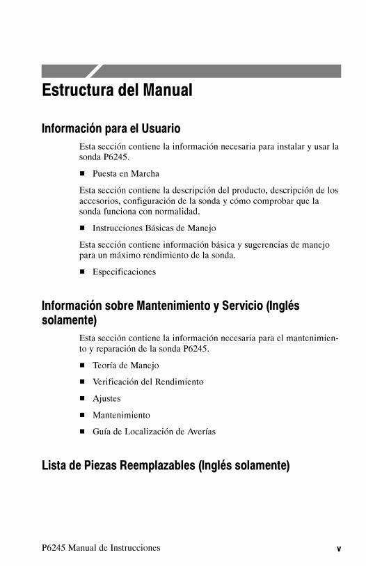
P6245 Manual de Instrucciones v
Estructura del Manual
Información para el Usuario
Esta sección contiene la información necesaria para instalar y usar lasonda P6245.
� Puesta en Marcha
Esta sección contiene la descripción del producto, descripción de losaccesorios, configuración de la sonda y cómo comprobar que lasonda funciona con normalidad.
� Instrucciones Básicas de Manejo
Esta sección contiene información básica y sugerencias de manejopara un máximo rendimiento de la sonda.
� Especificaciones
Información sobre Mantenimiento y Servicio (Ingléssolamente)
Esta sección contiene la información necesaria para el mantenimien-to y reparación de la sonda P6245.
� Teoría de Manejo
� Verificación del Rendimiento
� Ajustes
� Mantenimiento
� Guía de Localización de Averías
Lista de Piezas Reemplazables (Inglés solamente)

Estructura del Manual
vi P6245 Manual de Instrucciones

Puesta en Marcha


P6245 Manual de Instrucciones 1- 1
Descripción del Producto
El producto P6245 de Tektronix es una sonda FET activa de 1,5GHz(sonda solamente) y 10X con una capacitancia de entrada de menosde 1pF. La baja capacitancia de entrada de la sonda P6245 y altaresistencia de entrada minimizan la carga del circuito en un ampliorango de ancho de banda. El perfil pequeño y cabezal de masa bajade la sonda P6245 hace que el sondeo manual de circuitos densos seauna tarea rápida y fácil. Las puntas y adaptadores accesoriospermiten el uso de la sonda P6245 en una amplia variedad deestructuras de circuitos.
La sonda P6245 se alimenta a través de una interfaz TEKPROBEentre la caja de compensación de la sonda y el osciloscopio. Lasonda P6245 puede usarse con osciloscopios e instrumentos que nosean TEKPROBE usando la fuente de alimentación de sondaopcional 1103 de Tektronix.
A fin de conocer completamente la capacidad de la sonda, sírvaseleer las secciones Puesta en Marcha e Instrucciones Básicas deManejo de este manual.
Accesorios estándar
La sonda P6245 se envía con los siguientes accesorios estándar:
� Puntas de prueba estándar
� Cables de prueba de microcircuito SMT KlipChip™
� Adaptador para cable en Y
� Adaptador de ángulo derecho
� Adaptadores de señal--conexión a tierra
� Cables de conexión a tierra de 7,6cm y 15cm
� Cable de conexión a tierra de baja inductancia
� Anillos marcadores
� Manual de Instrucciones

Descripción del Producto
1- 2 P6245 Manual de Instrucciones
Para información sobre el número de pieza de accesorios estándar yopcionales, consulte la sección de Piezas Reemplazables de estemanual.
Servicio de Asistencia al Cliente
Para ayudarle a obtener el máximo rendimiento de su sonda,Tektronix ofrece los siguientes servicios de apoyo al cliente:
Asistencia de Funcionamiento
Si se encuentra fuera de los Estados Unidos o Canadá, por favorcomuníquese con el Centro de Servicio de Tektronix más cercano austed.
Asistencia de Mantenimiento y Reparaciones
Si la sonda necesita alguna reparación que no esté incluida en laayuda ofrecida por este manual, por favor comuníquese con elCentro de Servicio de Tektronix más cercano.
Asistencia de Ventas
Si se encuentra fuera de los Estados Unidos o Canadá, por favorcomuníquese con el Centro de Servicio de Tektronix más cercano austed.

P6245 Manual de Instrucciones 1- 3
Características y Accesorios
La sonda P6245 cuenta con varias características y accesoriosdiseñados para simplificar la tarea de tomar mediciones. Le rogamosque se tome un momento para informarse de estos elementos y sususos.
Receptáculode la punta de
prueba
Ranura deestabilización
Receptáculode conexióna tierra
Conjunto del Cabezal de la Sonda. Elcabezal de la sonda está diseñado para un usofácil y alto rendimiento. Su pequeño tamaño haceque sea fácil de manejar en áreas estrechas.
El receptáculo de la punta de prueba tiene unasdimensiones adecuadas para presionarfácilmente sobre clavijas de 0,025 pulgadas paraacceso directo. El receptáculo de conexión atierra proporciona un recorrido corto de conexióna tierra para conexiones altamente fiables deconexión a tierra.
La ranura de estabilización le permite usarclavijas adyacentes para reducir las presiones enla sonda y las clavijas. Para más información, vealas páginas 1--7 y 2--8.
Interfaz TEKPROBE™. La interfaz TEKPROBEproporciona una vía de comunicación entre la sonday el osciloscopio. Las clavijas de contacto proporcio-nan la transferencia de datos característicos de laalimentación, señal, offset y sonda. Para másinformación, vea la página 4--2.
Si su osciloscopio no soporta la interfaz TEKPROBE,puede usar la fuente de alimentación de sondaopcional 1103 como una interfaz efectiva. Para másinformación, comuníquese con su representantelocal de Tektronix.

Características y Accesorios
1- 4 P6245 Manual de Instrucciones
Punta de pruebaencajable
Punta de Prueba Encajable. Use la punta deprueba encajable para propósitos generales demedición a mano. La punta se puede utilizartambién como punto de prueba temporal. Paramás información, vea la página 2--7.
La punta de prueba encajable también puedeusarse con los demás cables y adaptadores conreceptáculos.
Instalación de la Punta de PruebaEncajable. Conecte la punta de pruebaencajable introduciendo la punta en el receptácu-lo de la sonda y presionando sobre la punta hastaque quede encajada. Se puede usar cualquierade los dos lados de la punta.
No fuerce la punta. Debe tener cuidado tambiénde no pincharse con la punta afilada. Para quitarla punta, agárrela suavemente con unos alicatespequeños y tire de ella hacia afuera.
Adaptadorde ánguloderecho
Adaptador de Ángulo Derecho. Use eladaptador de ángulo derecho para sondeos debajo perfil de clavijas cuadradas de 0,025 dediámetro.
El adaptador de ángulo derecho permite que lasonda P6245 se pueda poner en posición planacontra una placa de circuito impreso. Esto facilitael sondeo en circuitos verticales como placasposteriores de interconexiones de ordenadores ocomunicaciones, o en áreas estrechas comoentre tarjetas de circuitos.
El adaptador de ángulo derecho puede usarsedirectamente con el cabezal de la sonda oconectado a un adaptador de cable en Y o cablesde conexión a tierra.
El adaptador de ángulo derecho se conecta de lamisma manera que la punta de prueba encajabley se quita fácilmente con la mano.
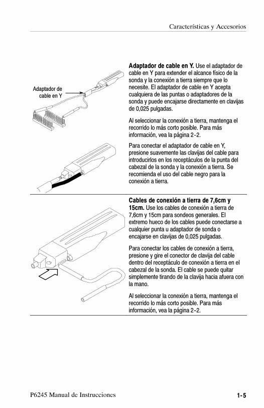
Características y Accesorios
P6245 Manual de Instrucciones 1- 5
Adaptador decable en Y
Adaptador de cable en Y. Use el adaptador decable en Y para extender el alcance físico de lasonda y la conexión a tierra siempre que lonecesite. El adaptador de cable en Y aceptacualquiera de las puntas o adaptadores de lasonda y puede encajarse directamente en clavijasde 0,025 pulgadas.
Al seleccionar la conexión a tierra, mantenga elrecorrido lo más corto posible. Para másinformación, vea la página 2--2.
Para conectar el adaptador de cable en Y,presione suavemente las clavijas del cable paraintroducirlos en los receptáculos de la punta delcabezal de la sonda y la conexión a tierra. Serecomienda el uso del cable negro para laconexión a tierra.
Cables de conexión a tierra de 7,6cm y15cm. Use los cables de conexión a tierra de7,6cm y 15cm para sondeos generales. Elextremo hueco de los cables puede conectarse acualquier punta u adaptador de sonda oencajarse en clavijas de 0,025 pulgadas.
Para conectar los cables de conexión a tierra,presione y gire el conector de clavija del cabledentro del receptáculo de conexión a tierra en elcabezal de la sonda. El cable se puede quitarsimplemente tirando de la clavija hacia afuera conla mano.
Al seleccionar la conexión a tierra, mantenga elrecorrido lo más corto posible. Para másinformación, vea la página 2--2.

Características y Accesorios
1- 6 P6245 Manual de Instrucciones
Cable de conexión a tierra de bajainductancia. Use el adaptador de conexión atierra de baja inductancia para reducir considera-blemente la inductancia del cable de conexión atierra. Debido a que el cable de conexión a tierrasimplemente toca la referencia de tierra, puedemover fácilmente la sonda a diferentes puntos delaparato que esté probando.
Para conectarlo, presione el cable de conexión atierra dentro del receptáculo de conexión a tierradel cabezal de la sonda.
Al seleccionar la conexión a tierra, mantenga elrecorrido lo más corto posible. Para másinformación, vea la página 2--2.

Características y Accesorios
P6245 Manual de Instrucciones 1- 7
Adaptador deseñal--conexión
a tierra
AdaptadoresFlexLead
Adaptador de señal- conexión a tierra. Eladaptador de señal--conexión a tierra es idealpara uso con pares de señal/conexión a tierra enclavijas de 0,100 (tales como adaptadoresFlexLead™).
Conecte el adaptador de señal--conexión a tierrapresionándolo suavemente dentro del receptácu-lo de conexión a tierra en el cabezal de la sonda.
Asegúrese de usar la ranura de estabilizaciónsiempre que sea posible. Para más detalles, veala página 2--8.
KlipChip
Adaptador decable en Y
SMT KlipChip™. Use las pinzas de pruebaSMT KlipChip para acceder a circuitos frágiles ydensos.
Las pinzas de prueba KlipChip pueden conec-tarse a cables de conexión a tierra de 7,6cm y15cm. Solamente tiene que presionar elreceptáculo del cable dentro de la manivela delKlipChip.
El cuerpo del KlipChip gira libremente, permitien-do una mejor orientación de la sonda. Parareducir la presión y proporcionar un perfil másbajo sobre los componentes que están bajoprueba, la manga flexible del KlipChip se doblahasta un ángulo de 35 grados.

Características y Accesorios
1- 8 P6245 Manual de Instrucciones
Bandasmarcadorasen color
Bandas marcadoras en color. Conecte paresdel mismo color de bandas marcadoras en elcable del cabezal y la caja de compensación decada sonda. Las bandas marcadoras le permitenverificar rápidamente qué sonda está conectadaa qué canal del instrumento.
Punta de Prueba SureFoot™ (opcional). Lapunta SureFoot es una punta de prueba integral yguía en miniatura que permite sondeos fiables depaquetes SMD de paso pequeño. Conecte losadaptadores SureFoot de la misma manera quelas puntas de prueba encajables. Se pueden usarcon cualquiera de los cables accesorios conreceptáculos.
La punta de prueba amarilla SureFoot de 0,050pulgadas es compatible con paquetes JEDEC de50 milipulgadas como SOIC, PLCC, CLCC, etc.
La punta de prueba azul SureFoot de 0,025pulgadas es compatible con paquetes EIAJ yJEDEC de 0,65mm.
La punta de prueba roja SureFoot de 0,5pulgadas es compatible con paquetes EIAJ.

P6245 Manual de Instrucciones 1- 9
Configuración
La sonda P6245 proporciona al osciloscopio el número de modelode la sonda, número de serie y factor de atenuación. Cuando estáconectada a un osciloscopio de interfaz TEKPROBE, las lecturas dela pantalla se corrigen por el factor de atenuación de la sonda, laentrada del instrumento se ajusta a 50Ω y el acoplamiento a CC.
CAUTION. No intente instalar la sonda P6245 en un conector que no
sea TEKPROBE. Esto podría resultar en daño a la sonda y alconector. Si su osciloscopio no soporta la interfaz TEKPROBE, use
la fuente de alimentación de sonda opcional 1103 de Tektronix.
Si usa la sonda P6245 con la fuente de alimentación de sonda
opcional 1103 de Tektronix, asegúrese de tener una terminación de
50Ω en el osciloscopio. También debe poner el acoplamiento decanal del osciloscopio a CC.
El control de offset de la sonda está controlado por el osciloscopio.Si el osciloscopio usado no soporta la interfaz TEKPROBE, se puedeusar el control de offset de la fuente de alimentación de sondaopcional 1103 de Tektronix.
Offset de la Sonda
El offset de la sonda se puede ajustar para permitir el funcionamientodentro del rango lineal de la sonda. El uso del offset para cancelar loscomponentes de señal de CC proporciona un rendimiento máximo dela sonda. Vea la Figura 1--1 en la página 1--10.
NOTE. Consulte el manual del osciloscopio sobre las instruccionesespecíficas del control de operación y offset.

Configuración
1- 10 P6245 Manual de Instrucciones
Para ajustar el offset de la sonda, siga los siguiente pasos:
1. Ponga el acoplamiento del osciloscopio en GND.
2. Use el control de posición vertical para ajustar el nivel dereferencia de la pantalla del osciloscopio a cero.
3. Ajuste el acoplamiento del osciloscopio a CC y 5V/div.
4. Conecte la sonda al circuito.
5. Ajuste el offset de la sonda para llevar la traza a la referenciacero del osciloscopio.
6. Cambie la configuración de voltios/división al rango deseado,ajustando el offset para mantener la traza al nivel de referenciacero.
NOTE. La sonda P6245 tiene un rango de offset de �10V. El rango
de operación lineal es de �8V. Vea la Figura 1--1. Vea también lapágina 2--1 para más información.
Si se usan cursores en un osciloscopio TEKPROBE, la referencia
cero estará en la tensión de offset de la sonda.
0 V
+15 V
--15 V
+8 V
--8 V
+10 V
--10 V
+10 V
--10 V
Rango no operativo (+15 V Tensión máxima no destructiva de entrada)
Amplitud máximade la señal de CA
Rango offset máximo
Rango no operativo (--15 V Tensión máxima no destructiva de entrada)
Figure 1- 1: Limitaciones dinámicas y de offset

P6245 Manual de Instrucciones 1- 11
Comprobación del Funcionamiento
Después de instalar la sonda en el osciloscopio, se puede realizar unacomprobación del funcionamiento usando las conexiones deCOMPENSACIÓN DE LA SONDA en el panel frontal delosciloscopio. Vea la Figura 1--2.
Figure 1- 2: Conexiones de comprobación del funcionamiento de lasonda
1. Conecte la sonda al osciloscopio.
2. Ajuste el osciloscopio para que muestre el canal de la sonda.
3. Usando un cable de conexión a tierra y un SMT KlipChip,conecte la toma a tierra de la sonda a la conexión a tierra de laCOMPENSACIÓN DE SONDA del osciloscopio.
4. Usando una punta estándar, conecte la sonda a la terminal deseñal (SIGNAL) del osciloscopio.

Comprobación del Funcionamiento
1- 12 P6245 Manual de Instrucciones
5. Pulse AUTOSET (o ajuste el osciloscopio) para que muestre laforma de onda de calibración.
NOTE. Si el instrumento soporta rutinas de calibración de onda, éstees un buen momento para llevarlas a cabo.
6. Desconecte la sonda de la terminal de señal (SIGNAL) y conectea tierra la punta de la sonda. (Conecte el KlipChip a la punta dela sonda).
7. Con el offset de sonda en 0,0, la pantalla del osciloscopio debeestar en la referencia de conexión a tierra.
8. Ajuste los voltios/división del osciloscopio a 5V.
9. Ajuste el offset de la sonda. La forma de onda mostrada debevariar entre aproximadamente +10 y --10 voltios. (Un offset de+10V mostrará un nivel de --10V en el instrumento).
NOTE. Si no aparece ninguna forma de onda, compruebe el
acoplamiento vertical para asegurarse de que está en CC.
Si el ajuste de offset no surte efecto, ponga el acoplamiento verticalen CC.
Si está usando la fuente de alimentación de sonda opcional 1103 de
Tektronix, y la forma de onda aparece distorsionada, compruebe si la
terminación del osciloscopio es 50Ω..
Si esta comprobación del funcionamiento de la sonda no resulta apta,consulte la sección Guía de Localización de Averías de este manual.

Instrucciones Básicas de Manejo


P6245 Manual de Instrucciones 2- 1
Instrucciones Básicas de Manejo
Por favor siga estas instrucciones de manejo para obtener un máximorendimiento de la sonda P6245.
Tensión Máxima no Destructiva de Entrada
La sonda P6245 está protegida eléctricamente contra tensión estática;no obstante, si se aplican tensiones por encima de los límites de sucapacidad, se puede dañar el amplificador de la punta de prueba. Porfavor consulte la sección Especificaciones de este manual para infor--mación sobre la tensión y frecuencia máximas de funcionamiento.
Rango Dinámico Lineal de Entrada
El amplificador del cabezal de la sonda P6245 tiene un rango linealde funcionamiento limitado. Para mantener el error de linealidad deentrada por debajo del 4%, debe limitar la tensión de entrada de laseñal a �8V (incluyendo cualquier offset de CC).
Use el ajuste del offset de CC para mantener la sonda dentro de surango dinámico. El rango nominal de ajuste de offset de la sondaP6245 es�10V CC. Por ejemplo: para desviar un nivel +5V CC deun circuito, ajuste el offset a +5V.

Instrucciones Básicas de Manejo
2- 2 P6245 Manual de Instrucciones
Extensión del Cable de Conexión a Tierra
Cuando compruebe un circuito, debe usar siempre un cable deconexión a tierra lo más corto posible entre el cabezal de la sonda yla conexión a tierra del circuito.
La inductancia en serie añadida por la punta de prueba y el cable deconexión a tierra puede resultar en un circuito resonante; estecircuito puede causar una resonancia parásita dentro del ancho debanda del osciloscopio. Vea la figura 2--1.
Conexión a tierrade baja inductancia
Conexión a tierrade 7,6cm
Conexión a tierrade 15cm
Figure 2- 1: Distorsión de la forma de onda por la extensión del cable deconexión a tierra.
Inductancia del Cable de Conexión a Tierra
Al poner en contacto la punta de prueba con un elemento delcircuito, se está introduciendo una nueva resistencia, capacitancia einductancia en el circuito. Vea la Figura 2--2.

Instrucciones Básicas de Manejo
P6245 Manual de Instrucciones 2- 3
C in desonda1 pF
V fuente
R fuente
R in de sonda1 MΩ
L gl (cable de conexión a tierra)
Figure 2- 2: Circuito equivalente de cable de conexión a tierra
La degradación de resonancia y tiempo de subida puede filtrarse si elcontenido de la frecuencia de la degradación de la señal está más alládel ancho de banda del osciloscopio.
Puede determinar si los efectos del cable de conexión a tierra puedenser un problema en la aplicación que esté realizando si conoce laautoinductancia (L) y capacitancia (C) de la sonda y del cable deconexión a tierra. Con la siguiente fórmula, calcule la frecuenciaresonante (f0) aproximada a la que este circuito parásito resonará:
f0 =1
2π LC�
La ecuación anterior muestra que al reducir la inductancia del cablede conexión a tierra sube la frecuencia resonante. Si sus medicionesse ven afectadas por resonancia, su objetivo es reducir la inductanciadel recorrido de conexión a tierra hasta que la frecuencia resonanteresultante esté bien por encima de la frecuencia de sus mediciones.
Los contactos de conexión a tierra con baja inductancia descritos enla sección Accesorios pueden ayudar a reducir los efectos de lainductancia del cable de conexión a tierra en sus mediciones.

Instrucciones Básicas de Manejo
2- 4 P6245 Manual de Instrucciones

P6245 Manual de Instrucciones 2- 5
Sugerencias Útiles
Siga las siguientes sugerencias útiles para sondeos más fáciles y sinruido.
Conexión a Tierra de Baja Inductancia
Si se coloca un plano de conexión a tierra sobre el paquete bajoprueba se puede minimizar la extensión del cable de conexión atierra y la inductancia. Vea la Figura 2--3.
Figure 2- 3: Conexión a tierra de baja inductancia
Ponga un pequeño trozo de chapa de cobre sobre el paquete yconéctelo a la conexión a tierra del paquete. Use el cable deconexión a tierra de baja inductancia proporcionado con la sondaP6245 para mantener el recorrido de conexión a tierra lo más cortoposible.

Sugerencias Útiles
2- 6 P6245 Manual de Instrucciones
Este método es muy útil al hacer muchas mediciones en el mismopaquete. Al colocar un plano de conexión a tierra sobre el paquete, elsondeo resulta más fácil y evita añadir extensión de conexión a tierray distorsión innecesarias.
Conexión a Tierra SureFoot™
Si no puede usar el método de conexión a tierra de baja inductanciarecomendado, puede hacer la conexión a tierra de la sonda al paqueteusando un adaptador SureFoot. Vea la Figura 2--4.
Figure 2- 4: Uso del adaptador SureFoot para conexión a tierra
Puede usar el adaptador SureFoot en el extremo de un cable corto deconexión a tierra para conectar directamente a la conexión a tierradel paquete. Este método es preferible al de usar una conexión atierra de un circuito adyacente, ya que es el recorrido de conexión atierra más corto posible.

Sugerencias Útiles
P6245 Manual de Instrucciones 2- 7
Uso de Puntas de Sonda como Puntos de Prueba
Se puede soldar a un circuito una punta de sonda encajable o unaclavija cuadrada de 0,025 para usarla como punto de pruebatemporal. Vea la Figura 2--5.
Suelde la punta a un cable o clavija con una plancha de soldar debaja potencia. Presione el cabezal de la sonda sobre la punta parahacer una medición y, una vez haya finalizado, tire del cabezal haciaafuera.
Puede quitar la punta de prueba y volver a usarla desoldándola delcircuito y volviendo a soldarla en otro circuito en el futuro.
Soldadura
Figure 2- 5: Uso de puntas de sonda como puntos de prueba
NOTE. No se recomienda el uso de trozos de cable de cobre macizocomo punto de prueba. Si el cable se rompe dentro del receptáculo
de la sonda, es posible que no se pueda quitar y que obstruya otras
puntas accesorias.

Sugerencias Útiles
2- 8 P6245 Manual de Instrucciones
Estabilización de la Punta de Prueba
El cabezal de la sonda P6245 tiene una ranura estabilizadora parausarla con clavijas espaciadas a 0,100 pulgadas. Vea el dibujodetallado del cabezal de la sonda en la página 1--3.
A medida que se presiona la sonda sobre la clavija, una clavijaadyacente puede insertarse en la ranura de estabilización de la sonda.Vea la Figura 2--6. De esta manera se evita aplicar demasiada presiónsobre la punta de la sonda o sobre las clavijas.
Ranura deestabilización
Figure 2- 6: Ranura de estabilización de la punta de prueba
Así, el adaptador de señal--conexión a tierra descansa sobre la clavijade estabilización sin riesgo de que se salga de su sitio.

Especificaciones


P6245 Manual de Instrucciones 3- 1
Especificaciones
Estas especificaciones son aplicables a la sonda P6245 cuando se usacon un osciloscopio TDS 684A.
Antes de tomar las mediciones, es necesario dejar que la sonda y elinstrumento se calienten por 20 minutos.
CAUTION. No aplique a la sonda tensiones por encima del rango de
tensión no destructiva de entrada. Ello puede resultar en daño a la
sonda o al circuito bajo prueba.
Table 3- 1: Especificaciones eléctricas garantizadas
Ancho de banda analógico (sistema) 1GHz
Precisión de atenuación de CC (sondasolamente)
10:1�2%
Salida cero �5mV o menos en la salida de la sonda
�50mV o menos mostrados en la pantallacon interfaz TEKPROBE
Tiempo de subida (sonda solamente) 267ps en osciloscopios≥10GHz

Especificaciones
3- 2 P6245 Manual de Instrucciones
Table 3- 2: Características eléctricas típicas
Ancho de banda analógico (sonda sola-mente)
1,5GHz en osciloscopios≥10GHz(Vea la Figura 3--1)
Rango dinámico lineal de entrada De --8V a +8Vequivalente a de --0,8V a +0,8V en la salidade la sonda
Linealidad �4% o menos de rango dinámico
Rango de tensión no destructiva de entrada De --15V a +15V (CC + CA de pico)(Vea la Figura 3--2)
Resistencia de entrada 1MΩ a CC. (Vea la Figura 3--4)
Capacitancia de entrada ≤1,0pF
Rango de offset De --10V a +10V
Variación de offset de CC 100�V/°C o menos en la salida de la sonda
1mV/°C o menos mostrado en la pantallacon interfaz TEKPROBE
Tiempo de retardo 5,3 ns ±0,2 nanosegundos

Especificaciones
P6245 Manual de Instrucciones 3- 3
0 dB
--1 dB
--2 dB
--3 dB
--4 dB
--5 dB
--6 dB
--7 dB
--8 dB
+1 dB
+2 dB
1 MHz 1 GHz100 MHz10 MHz
Figure 3- 1: Ancho de banda típico
25 V
20 V
15 V
1 MHz 10 MHz 100 MHz
5 V
0 V
10 V10V at 1 GHz
6V at 3 GHz
1 GHz
Figure 3- 2: Reducción de tensión en comparación con la frecuencia

Especificaciones
3- 4 P6245 Manual de Instrucciones
--20 V 0 V--10 V 10 V 20 V
150 mV
100 mV
50 mV
--100 mV
0 mV
--50 mV
--150 mV
Errordevisualización
VIN
Figure 3- 3: Error típico de linealidad en comparación con VIN
10 MΩ
1 MΩ
100 kΩ
10kΩ
1 kΩ
100Ω
10Ω
100 Hz 1 GHz100 kHz1 kHz 10 kHz 1 MHz 10 MHz 100 MHz
Figure 3- 4: Impedancia típica de entrada en comparación con lafrecuencia

Especificaciones
P6245 Manual de Instrucciones 3- 5
20°
0°
--20°
--40°
100 Hz 1 GHz100 kHz1 kHz 10 kHz 1 MHz 10 MHz 100 MHz
--80°
--100°
--60°
Figure 3- 5: Fase típica en comparación con la frecuencia

Especificaciones
3- 6 P6245 Manual de Instrucciones
Table 3- 3: Características físicas
Peso neto 63,8 g
Extensión del cable 1,3 metros
Table 3- 4: Características medioambientales
Temperatura de funcionamiento De 0°C a +50°C.
La exposición medioambiental es el procedimientoestablecido por el Estándar de Diseño de Tektronix062--2847--00 para equipos de la Clase 5.
Temperatura de no funcionamiento De --40°C a +71°C.
La exposición medioambiental es el procedimientoestablecido por el Estándar de Diseño de Tektronix062--2847--00 para equipos de la Clase 5.
Humedad La exposición medioambiental es el procedimientoestablecido por el Estándar de Diseño de Tektronix062--2847--00 para equipos de la Clase 5.
Vibración y choque del productoempaquetado
El producto empaquetado califica bajo el Ciclo I deDistribución, Nivel II de Seguridad, de productosempaquetados de 0 a 9,1kg. Se omite la prueba 2para apilamiento en almacenes y vehículos(compresión).
Estándar de Tektronix 062--2858--00, Rev. B, Clase 5.
Altitud En funcionamiento: 4,570m
Fuera de funcionamiento: 15,240m

Service Information


P6245 Instruction Manual i
Service Information Contents
Theory of Operation
Probe Head and Cable Assembly 4--1. . . . . . . . . . . . . . . . . . . . . . .Compensation Box 4--2. . . . . . . . . . . . . . . . . . . . . . . . . . . . . . . . . . .
Offset Amplifier 4--2. . . . . . . . . . . . . . . . . . . . . . . . . . . . . . . . . .Probe Identification EEPROM 4--2. . . . . . . . . . . . . . . . . . . . . .TEKPROBE™ Interface 4--2. . . . . . . . . . . . . . . . . . . . . . . . . . . .
Performance Verification
Equipment Required 4--4. . . . . . . . . . . . . . . . . . . . . . . . . . . . . . . . .Equipment Setup 4--4. . . . . . . . . . . . . . . . . . . . . . . . . . . . . . . . . . . .Offset Zero 4--5. . . . . . . . . . . . . . . . . . . . . . . . . . . . . . . . . . . . . . . . .DC Accuracy 4--6. . . . . . . . . . . . . . . . . . . . . . . . . . . . . . . . . . . . . . .
Adjustments
Adjustment Locations 4--9. . . . . . . . . . . . . . . . . . . . . . . . . . . . . . . .Offset Zero 4--10. . . . . . . . . . . . . . . . . . . . . . . . . . . . . . . . . . . . . . . . .Offset Range 4--11. . . . . . . . . . . . . . . . . . . . . . . . . . . . . . . . . . . . . . .
Maintenance
Replacing TEKPROBE™ Interface Pins 4--13. . . . . . . . . . . . . . . . . .Removing and Replacing the Compensation Box Covers 4--14. . . .Removing and Replacing the TEKPROBE™ Interface Collar 4--16.Inspection and Cleaning 4--17. . . . . . . . . . . . . . . . . . . . . . . . . . . . . .Replacement Parts 4--17. . . . . . . . . . . . . . . . . . . . . . . . . . . . . . . . . . .Preparation for Shipment 4--17. . . . . . . . . . . . . . . . . . . . . . . . . . . . . .
Troubleshooting

Service Information Contents
ii P6245 Instruction Manual
Replaceable Parts
Parts Ordering Information 5--1. . . . . . . . . . . . . . . . . . . . . . . . . . . .Using the Replaceable Parts List 5--2. . . . . . . . . . . . . . . . . . . . . . . .Item Names 5--2. . . . . . . . . . . . . . . . . . . . . . . . . . . . . . . . . . . . . . . .Indentation System 5--2. . . . . . . . . . . . . . . . . . . . . . . . . . . . . . . . . .Abbreviations 5--2. . . . . . . . . . . . . . . . . . . . . . . . . . . . . . . . . . . . . . .
List of Figures
Figure 4--1: P6245 Simplified Schematic Diagram 4--1. . . . . . . . .Figure 4--2: TEKPROBE Interface 4--3. . . . . . . . . . . . . . . . . . . . . .Figure 4--3: P6245 DC Accuracy Setup 4--7. . . . . . . . . . . . . . . . . .Figure 4--4: P6245 Adjustment Locations 4--9. . . . . . . . . . . . . . . . .Figure 4--5: Replacing TEKPROBE Interface Pins 4--13. . . . . . . . .Figure 4--6: Removing the Compensation Box Covers 4--14. . . . . . .Figure 4--7: Replacing the Compensation Box Cover 4--15. . . . . . . .Figure 4--8: Replacing the TEKPROBE collar 4--16. . . . . . . . . . . . .Figure 4--9: Compensation Box Test Point Locations 4--20. . . . . . . .
Figure 5--1: P6245 Replaceable Parts 5--4. . . . . . . . . . . . . . . . . . . .Figure 5--2: P6245 Standard Accessories 5--6. . . . . . . . . . . . . . . . .Figure 5--3: P6245 Optional Accessories 5--8. . . . . . . . . . . . . . . . .

The following servicing instructions are for use only byqualified personnel. To avoid injury, do not perform anyservicing other than that stated in the operating instructionsunless you are qualified to do so. Refer to all safetysummaries before performing any service.
WARNING


P6245 Instruction Manual 4- 1
Theory of Operation
There are no user replaceable parts within the probe or thecompensation box; however, this theory of operation is provided toassist you in isolating failures to either the probe or the hostoscilloscope. Refer to Figure 4--1 for the probe’s simplifiedschematic.
OffsetGain
OffsetZero
Offset Ampifier
EEPROM
Offset to probe
Probe-TipAmpifier
Signal OutProbe Tip
±1 V Offset
Probe ID Out
+5 V
--5 V
Ground
ProbeCable
TEKPROBEInterface
Probe Head Compensation Box Oscilloscope
Clock In
+5 --5
Figure 4- 1: P6245 Simplified Schematic Diagram
Probe Head and Cable Assembly
The probe head assembly contains an active amplifier circuit thatbuffers and amplifies the input signal. The amplifier receives powerand an offset level from the compensation box assembly via thecable assembly.

Theory of Operation
4- 2 P6245 Instruction Manual
All signal amplification and buffering is performed in the probe headassembly. No further amplification takes place in the compensationbox.
Compensation Box
The compensation box contains the following circuits:
� Offset amplifier
� Probe identification EEPROM
� TEKPROBE interface
Offset Amplifier
The offset amplifier is used to offset the input signal’s DC compo-nent so that it stays at the optimal point of the probe’s linear dynamicrange. For more information on the linear dynamic range characteris-tic, refer to the notes on page 2--1.
The offset amplifier receives offset information as a ±1 VDC voltagefrom the oscilloscope. The amplfier then amplifies it to match theprobe characteristics and applies it to the probe hybrid circuit.
The offset amplifier has two adjustments: offset zero and offset gain.These adjustments rarely need attention; however, detailedadjustment instructions are in the Adjustment section on page 4--9.
Probe Identification EEPROM
The probe identification EEPROM is used to configure theoscilloscope to the probe. The EEPROM receives a clock input fromthe oscilloscope, and information about the probe is passed to theoscilloscope.
TEKPROBE™ Interface
The TEKPROBE interface provides a communication path betweenthe probe and the oscilloscope. Contact pins provide power, signal,offset, and data transfer for the probe identification EEPROM.

Theory of Operation
P6245 Instruction Manual 4- 3
Figure 4--2 shows the TEKPROBE interface pin functions. Refer toyour oscilloscope’s service documenation for more detailedspecifications.
DataClock
+5 V
+15 V
--15 V
--5 V
Offset
Signal
Ground
Figure 4- 2: TEKPROBE Interface

Theory of Operation
4- 4 P6245 Instruction Manual

P6245 Instruction Manual 4- 5
Performance Verification
Equipment Required
Table 4- 1: Equipment Required for Performance Verification
Item DescriptionPerformanceRequirement Recommended Example
Oscilloscope TEKPROBE interface Tektronix TDS 684A
TEKPROBE Power Supply Tektronix 1103
DC Power Supply 10.00 ±.01 VDC at 1 mA Tektronix PS281
DC Voltmeter 0.5% accuracy at 2 VDC Tektronix CDM250
Feedthrough Termination 50Ω ± 0.50Ω 011--0129--00
BNC to BNC coaxial cable 50Ω coaxial cable 012--1342--00
BNC to Banana adapter BNC Female to DualBanana
103--0090--00
Equipment Setup
1. Connect the probe to the oscilloscope.
2. Connect a Y-lead adapter with KlipChip adapters attached to theP6245.
3. Turn on the oscilloscope and enable the channel.
4. Set the channel’s vertical offset to 0.00 V.
5. Turn on the power supply and set to +2.00 VDC.
6. Connect the meter to measure the power supply output.
7. Allow 30 minutes for the equipment to warm up.

Performance Verification
4- 6 P6245 Instruction Manual
NOTE. If your oscilloscope has a probe calibration routine, run itbefore making any of the following checks. Refer to the oscilloscope’sinstruction manual for more information.
Offset Zero
Use this procedure to verify the probe’s offset zero.
1. Ground the probe tip by connecting the probe tip to the probeground socket. (Connecting the two KlipChip adapters together isrecommended.)
2. Set the channel’s vertical offset to 0.00 V.
3. Measure the displayed DC level.
The displayed DC level should be 0.00 V ±50 mV. (±5 mV whenmeasured directly without the probe attenuation factor.)

Performance Verification
P6245 Instruction Manual 4- 7
DC Accuracy
Use this procedure to verify the probe’s DC accuracy. Beforebeginning, read the procedure through completely.
1. Connect the test equipment as shown in Figure 4--3.
2. Attach the probe to a TEKPROBE interface on the 1103 powersupply.
3. Set the 1103 offset VAR/0V to 0V.
4. Set the multimeter to read DC volts.
5. Connect the probe tip and ground to the power supply using theY-lead and KlipChip adapters.
6. Allow 30 minutes for the equipment to warm up.
1103Power Supply
-- +
Power Supply
+
Digital Multimeter
--
BNC to DualBanana Adapter
50Ω PrecisionTerminator
Figure 4- 3: P6245 DC Accuracy Setup
7. Set the power supply to +2.000 V. Record the power supplyoutput as Vmax.
8. Measure and record the multimeter reading as M1.
9. Set the power supply to --2.000 V. Record the power supplyoutput as Vmin.

Performance Verification
4- 8 P6245 Instruction Manual
10.Measure and record the multimeter reading as M2.
NOTE. If you are unable to set the power supply precisely, record theactual readings and determine the absolute difference.|Vmax -- Vmin| = difference.
Divide the difference by 10 to account for the probe’s idealattenuation factor. For example: 0.4 is the difference between +2 and--2, divided by 10.
11. Determine the percent error by using the formula below:
%Error = [M1−M20.4
− 1]× 100%
The calculated error should be ≤2%.
NOTE. An unaccceptable error value may result if a low tolerancetermination is substituted for the recommended termination.

P6245 Instruction Manual 4- 9
Adjustments
The P6245 has two internal controls: offset zero and offset range.These controls rarely need to be adjusted, and only should bechanged after a probe calibration and functional check has beenperformed on the oscilloscope.
In order to make adjustments to the probe, the compensation box topcover needs to be removed with the optional release tool. Refer topage 4--14. Use the optional adjustment tool for making anyadjustments.
Adjustment Locations
Refer to Figure 4--4 for the location of the offset zero and offsetrange controls.
Offset Amp
EEPROM
Offset RangeAdjust
Offset ZeroAdjust
Figure 4- 4: P6245 Adjustment Locations

Adjustments
4- 10 P6245 Instruction Manual
Offset Zero
Use this procedure to adjust the probe’s offset zero.
NOTE. If your oscilloscope supports a probe calibration routine,clear the probe calibration constants at this time.
If the offset zero is adjusted, perform a functional check of the offsetrange before closing the compensation box.
1. Ground the probe tip by connecting the probe tip to the probeground socket.
2. Set the channel’s vertical offset to 0.00 V.
3. Measure the displayed DC level.
4. Adjust Offset Zero for 0.00 ± 50 mV. (±5 mV when measureddirectly without attenuation factor.)

Adjustments
P6245 Instruction Manual 4- 11
Offset Range
Use this procedure to adjust the offset range of the probe. The offsetzero of the probe should be checked before making any adjustmentto the offset range.
The offset range of the probe is approximately --10 to +10 volts. Theoffset range is not warranted; however, this adjustment procedure isprovided for your convenience.
NOTE. If you are using an 1103 Probe Power Supply, make sure thatthe oscilloscope is set to 50Ω termination with DC coupling.
See Figure 4--4 for the location of the offset range adjustment.
1. Set the power supply (using the DMM) to +10.00 VDC. (If10.00 V cannot be set exactly, set the power supply just below10.00 V.)
2. Connect the probe to the power supply as shown in Figure 4--3.
3. Set the channel’s vertical offset to match the DMM reading.
4. Set the channel’s vertical range to 0.1V/div.
5. Observe the DC value of the displayed trace.
6. Adjust Offset Range for an oscilloscope reading that matches theDMM reading.
NOTE. After the offset zero and offset range have been adjusted,perform a probe calibration and functional check to verify perfor-mance.

Adjustments
4- 12 P6245 Instruction Manual

P6245 Instruction Manual 4- 13
Maintenance
This section details the maintenance and repair procedures for theP6245.
Replacing TEKPROBE™ Interface Pins
TEKPROBE interface pins can stick and fail to make contact aftertime. Periodically check to see that each of the interface pins movefreely and fully extends out of the interface. If any pin fails to movefreely and fully extend, it should be replaced.
To remove a TEKPROBE interface pin, firmly grasp the pointed tipwith pliers and pull the pin out of the connector. See Figure 4--5.
No tools are required to install a replacement pin. Insert a new pininto the connector socket as far as possible using finger pressure. Ifnecessary, seat the pin into the connector by pressing the tip gentlybut firmly against a hard surface, such as a wood block or table top.
Figure 4- 5: Replacing TEKPROBE Interface Pins

Maintenance
4- 14 P6245 Instruction Manual
Removing and Replacing the Compensation Box Covers
Follow these steps to open the compensation box.
1. Press the optional release tool pins into the compensation boxcover catches and gently lift the cover off a small distance. Referto Figure 4--6.
2. Hold the open edge apart, and use the tool to open the other sideof the compensation box.
3. With both sides of the box open, gently separate the two halves ofthe compensation box.
CoverCatches
Figure 4- 6: Removing the Compensation Box Covers

Maintenance
P6245 Instruction Manual 4- 15
To replace the covers, follow these steps:
1. Align the TEKPROBE interface and the strain relief notches withthe tabs on the cover. Refer to Figure 4--7.
2. Press the cover catches in so that the cover can be lowered.
3. Slide the tab into the notch.
4. Firmly press the pieces together until the cover catches snap intoplace.
Tab
Figure 4- 7: Replacing the Compensation Box Cover

Maintenance
4- 16 P6245 Instruction Manual
Removing and Replacing the TEKPROBE™ Interface Collar
To remove the TEKPROBE interface collar, firmly grasp thecompensation box body with one hand, and the TEKPROBEinterface collar with the other hand. Firmly pull the interface collaroff.
To replace the collar, first note the pin configuration on thecompensation box, and their holes in the interface collar. The groupof three pins fit through the smaller of the two holes in the interfacecollar. See Figure 4--8.
Align the tab to the slot and gently press the two pieces together. SeeFigure 4--8.
Once installed, the TEKPROBE collar should rotate freely to lockand unlock.
Tab
Slot
Figure 4- 8: Replacing the TEKPROBE collar

Maintenance
P6245 Instruction Manual 4- 17
Inspection and Cleaning
To prevent damage to probe materials, avoid using chemicals thatcontain benzine, benzene, toluene, xylene, acetone, or similarsolvents.
Do not immerse the probe or use abrasive cleaners.
Dirt may be removed with a soft cloth dampened with a milddetergent and water solution, or isopropyl alcohol.
Replacement Parts
Refer to the Replaceable Parts section for a list of customerreplacement parts. Due to the sophisticated design of the P6245,there are no user replaceable parts within the probe.
Preparation for Shipment
If the original packaging is unfit for use or not available, use thefollowing packaging guidelines:
1. Use a corrugated cardboard shipping carton having insidedimensions at least one inch greater than the probe dimensions.The box should have a carton test strength of at least 200 pounds.
2. Put the probe into a plastic bag or wrap to protect it fromdampness.
3. Place the probe into the box and stabilize it with light packingmaterial.
4. Seal the carton with shipping tape.

Maintenance
4- 18 P6245 Instruction Manual

P6245 Instruction Manual 4- 19
Troubleshooting
This troubleshooting documentation details isolation to either theprobe or the TEKPROBE oscilloscope.
To troubleshoot the P6245, the probe must be attached to anoperating TEKPROBE interface oscilloscope with the top cover ofthe compensation box removed. Refer to page 4--14 for instructionson opening the compensation box.
The host instrument should be set to the following settings:
� 50 Ω termination at instrument.
� DC coupling
CAUTION. Observe caution when probing in the compensationbox. Operating voltages will be present. Be careful not to touchor ground energized components.
Work at a Level 1 ESD workstation when performing troubleshoot-ing. The compensation box contains static sensitive devices.

Troubleshooting
4- 20 P6245 Instruction Manual
+5(Red)
--5(White)
Offset(Blue)
Ground(Black)
Data--5
Offset
Clock
+5
Figure 4- 9: Compensation Box Test Point Locations
Refer to Table 4--2 for troubleshooting proceedures, and Figure 4--9for troubleshooting test points.
Table 4- 2: Troubleshooting Guide
Symptom Checks Result Action
No Signal Out Check known signal
Go to Probe Power
No signal.
Probe power OK.
Continue checks
Turn in probe.
Distorted ornonlinear signal
Instrument set to50Ω termination?
No Set termination to50Ω, or install afeedthroughtermination at theinstrument input.
Yes Continue
Distorted ornonlinear signal
Signal within lineardynamic range? Seepage 2--1.
No Set channel’s verticaloffset to match signalcharacteristic.
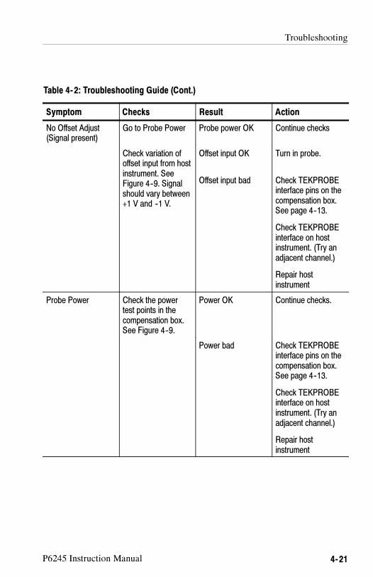
Troubleshooting
P6245 Instruction Manual 4- 21
Table 4- 2: Troubleshooting Guide (Cont.)
Symptom ActionResultChecks
No Offset Adjust(Signal present)
Go to Probe Power Probe power OK Continue checks
Check variation ofoffset input from hostinstrument. SeeFigure 4--9. Signalshould vary between+1 V and --1 V.
Offset input OK
Offset input bad
Turn in probe.
Check TEKPROBEinterface pins on thecompensation box.See page 4--13.
Check TEKPROBEinterface on hostinstrument. (Try anadjacent channel.)
Repair hostinstrument
Probe Power Check the powertest points in thecompensation box.See Figure 4--9.
Power OK Continue checks.
Power bad Check TEKPROBEinterface pins on thecompensation box.See page 4--13.
Check TEKPROBEinterface on hostinstrument. (Try anadjacent channel.)
Repair hostinstrument

Troubleshooting
4- 22 P6245 Instruction Manual

Replaceable Parts


P6245 Instruction Manual 5- 1
Replaceable Parts
This section contains a list of the P6245’s replaceable parts. Use thislist to identify and order replacement parts.
Parts Ordering Information
Replacement parts are available from or through your localTektronix, Inc. service center or representative.
Changes to Tektronix instruments are sometimes made to accommo-date improved components as they become available and to give youthe benefit of the latest circuit improvements. Therefore, whenordering parts, it is important to include the following information inyour order:
� Part number
� Instrument type or model number
� Instrument serial number
� Instrument modification number, if applicable
If a part you order has been replaced with a different or improvedpart, your local Tektronix service center or representative willcontact you concerning any change in the part number.

Replaceable Parts
5- 2 P6245 Instruction Manual
Using the Replaceable Parts List
The tabular information in the Replaceable Parts List is arranged forquick retrieval. Understanding the structure and features of the listwill help you find the all the information you need for orderingreplacement parts.
Item Names
In the Replaceable Parts List, an Item Name is separated from thedescription by a colon (:). Because of space limitations, an ItemName may sometimes appear as incomplete. For further Item Nameidentification, U.S. Federal Cataloging Handbook H6-1 can be usedwhere possible.
Indentation System
This parts list is indented to show the relationship between items.The following example is of the indentation system used in theDescription column:
1 2 3 4 5 Name & DescriptionAssembly and/or ComponentAttaching parts for Assembly and/or Component
(END ATTACHING PARTS)Detail Part of Assembly and/or ComponentAttaching parts for Detail Part
(END ATTACHING PARTS)Parts of Detail PartAttaching parts for Parts of Detail Part
(END ATTACHING PARTS)
Attaching parts always appear at the same indentation as the item itmounts, while the detail parts are indented to the right. Indenteditems are part of, and included with, the next higher indentation.Attaching parts must be purchased separately, unless otherwisespecified.
Abbreviations
Abbreviations conform to American National Standards Institute(ANSI) standard Y1.1

Replaceable Parts
P6245 Instruction Manual 5- 3
CROSSINDEX-MFR.CODENUMBERTOMANUFACTURER
Mfr.
Code
Manufacturer
Address
City,State,ZipCode
80009
TEKTRONIX
INC
14150SW
KARLBRAUNDR
POBOX500
BEAVERTONOR97077--0001

Replaceable Parts
P6245 Instruction Manual5- 4
1
32
3
Figure
5-1:P6245
ReplaceableParts

Replaceable Parts
P6245 Instruction Manual 5- 5
Fig.&
Index
No.
Tektronix
PartNo.
SerialNo.
Effective
Dscont
Qty
12345Nam
e&Description
Mfr.
Code
Mfr.PartNo.
5--1
P6245
1PROBE,FETACT:>1.5GHZ,10X
,<1P
F,TDSSERIES
80009
P6245
--1205--0191--01
1SHELL,ELE
CCONN:BNC,ABS,DOVEGRAY
80009
205--0191--01
--2131--3627--01
1CONTACT,ELE
C:GOLD
PLATEDTIP
80009
131--3627--01
--3200--4195--00
1COVER,COMPBOX:TOPANDBOTTOM,W/LABELS
&
RELE
ASETOOLS
80009
200--4195--00

Replaceable Parts
P6245 Instruction Manual5- 6
1
23
45
6
Figure
5-2:P6245
StandardAccessories

Replaceable Parts
P6245 Instruction Manual 5- 7
Fig.&
Index
No.
Tektronix
PartNo.
SerialNo.
Effective
Dscont
Qty
12345Nam
e&Description
Mfr.
Code
Mfr.PartNo.
5--2
STA
NDARDACCESSORIES
--1196--3410--00
1LE
AD,SET:TWO3.0L&6.OL,STRD,22AWG&TW
O3.0LBLA
CK&WHITE22
AWG,JACKTIP,TERM
CONNMALE
PIN,TWOZ--LEAD
80009
196--3410--00
--2016--1315--00
1MARKERKIT,ID:CABLE
MARKERBAND,2EACH,VARIOUS
COLO
RS
80009
016--1315--00
--3131--5638--10
1PROBE,TIP:PACKAGEOF10
80009
131--5638--10
--4----------------
2SPRINGADAPTER:RIGHTANGLE
--5----------------
2CONN,CONTACT:
--6----------------
4TIP,PROBE:MICROCKTTEST
070--8995--xx
1MANUAL,TECH:INSTRUCTION,P6245
80009
070--8995--xx
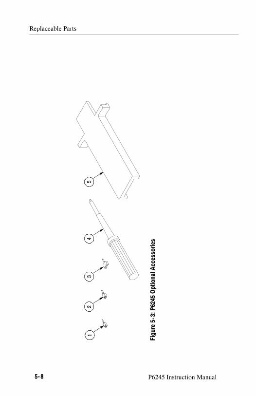
Replaceable Parts
P6245 Instruction Manual5- 8
12
34
5
Figure
5-3:P6245
OptionalAccessories

Replaceable Parts
P6245 Instruction Manual 5- 9
Fig.&
Index
No.
Tektronix
PartNo
Serial.No.
Effective
Dscont
Qty
12345Nam
e&Description
Mfr.
Code
Mfr.PartNo.
OPTIONALACCESSORIES
5--3--1
SF501
1ADPTR,SUREFOOT:50
MILJEDEC,PKGOF12
80009
SF501
--2SF502
1ADPTR,SUREFOOT:25
MILJEDEC,PKGOF12
80009
SF502
--3SF503
1ADPTR,SUREFOOT:0.5MMEIAJ,PKGOF12
80009
SF503
--4003--1433--01
1ADJU
STMENTTOOL,PKGOF5METALTIP
80009
003--1433--01
--5003--1383--00
1RLSETOOL,COVER:COMPBOX,POLYCARBONATE
80009
003--1383--00
1103
1TEKPROBEIF
PS:W
/OFFSET2CONN
80009
1103
SMG50
1TIP,PROBE:MICROCKTTEST,PKGOF20
(SEEFIGURE5--2--6)
80009
SMG50

Replaceable Parts
P6245 Instruction Manual5- 10