
P4S533-VM - Asusdlcdnet.asus.com/pub/ASUS/mb/sock478/p4s533-vm/e1058_p4s...This class B digital...
122
Motherboard ® P4S533-VM User Manual
Transcript of P4S533-VM - Asusdlcdnet.asus.com/pub/ASUS/mb/sock478/p4s533-vm/e1058_p4s...This class B digital...
Mot
herb
oard
®
P4S533-VM
User Manual

ii
Checklist
Copyright © 2002 ASUSTeK COMPUTER INC. All Rights Reserved.
No part of this manual, including the products and software described in it, may be reproduced,transmitted, transcribed, stored in a retrieval system, or translated into any language in anyform or by any means, except documentation kept by the purchaser for backup purposes,without the express written permission of ASUSTeK COMPUTER INC. (“ASUS”).
Product warranty or service will not be extended if: (1) the product is repaired, modified oraltered, unless such repair, modification of alteration is authorized in writing by ASUS; or (2)the serial number of the product is defaced or missing.
Products and corporate names appearing in this manual may or may not be registeredtrademarks or copyrights of their respective companies, and are used only for identificationor explanation and to the owners’ benefit, without intent to infringe.
The product name and revision number are both printed on the product itself. Manual revisionsare released for each product design represented by the digit before and after the period ofthe manual revision number. Manual updates are represented by the third digit in the manualrevision number.
For previous or updated manuals, BIOS, drivers, or product release information, contactASUS at: http://www.asus.com or through any of the means indicated on the following page.
ASUS PROVIDES THIS MANUAL “AS IS” WITHOUT WARRANTY OF ANY KIND, EITHER EXPRESSOR IMPLIED, INCLUDING BUT NOT LIMITED TO THE IMPLIED WARRANTIES OR CONDITIONS OFMERCHANTABILITY OR FITNESS FOR A PARTICULAR PURPOSE. IN NO EVENT SHALL ASUS, ITSDIRECTORS, OFFICERS, EMPLOYEES OR AGENTS BE LIABLE FOR ANY INDIRECT, SPECIAL,INCIDENTAL, OR CONSEQUENTIAL DAMAGES (INCLUDING DAMAGES FOR LOSS OF PROFITS,LOSS OF BUSINESS, LOSS OF USE OR DATA, INTERRUPTION OF BUSINESS AND THE LIKE),EVEN IF ASUS HAS BEEN ADVISED OF THE POSSIBILITY OF SUCH DAMAGES ARISING FROMANY DEFECT OR ERROR IN THIS MANUAL OR PRODUCT.
SPECIFICATIONS AND INFORMATION CONTAINED IN THIS MANUAL ARE FURNISHED FORINFORMATIONAL USE ONLY, AND ARE SUBJECT TO CHANGE AT ANY TIME WITHOUT NOTICE,AND SHOULD NOT BE CONSTRUED AS A COMMITMENT BY ASUS. ASUS ASSUMES NORESPONSIBILITY OR LIABILITY FOR ANY ERRORS OR INACCURACIES THAT MAY APPEAR INTHIS MANUAL, INCLUDING THE PRODUCTS AND SOFTWARE DESCRIBED IN IT.
P4S533-VME1058June 2002
iii
Fea
ture
s
About this guide
This user manual contains complete information for installing the ASUSP4S533-VM motherboard.
How this guide is organized• Chapter 1: Product introduction. A summary of product features and
special attributes of new technologies.
• Chapter 2: Hardware information. A list of hardware setup proceduresand descriptions of all jumpers and connectors on the motherboard.
• Chapter 3: Powering up. Describes the power up sequence withinformation on BIOS beep codes.
• Chapter 4: BIOS setup. How to change system settings using onboardBIOS firmware. Detailed descriptions of the BIOS parameters are supplied.
• Chapter 5: Software support. A summary of contents on themotherboard support CD ROM.
• Appendix and Glossary. Optional components and technical definitions.
• Index
Conventions used in this guideTo make sure that you perform set-up tasks properly, take note of the followingsymbols used throughout this manual.
WARNING! Information to prevent injury to yourself.
CAUTION! Information to prevent damage to the components.
IMPORTANT! Information that you MUST follow to complete a task.
NOTE! Tips and helpful information.
iv
Safeguards
Contents
About this guide .............................................................................. iiiHow this guide is organized .................................................... iiiConventions used in this guide ............................................... iii
Safety information ........................................................................... vi
FCC/CDC statements .................................................................... vii
ASUS contact information ............................................................. viii
Chapter 1: Product introduction ............................................. 1Welcome! ........................................................................................ 1
1.1 Package contents .................................................................. 1
1.2 Core Specifications ................................................................ 2
1.3 Value-added Solutions ........................................................... 3
1.4 Motherboard Components ...................................................... 41.4.1 Component Locations ................................................ 5
Chapter 2: Hardware information ............................................ 12.1 Motherboard installation ......................................................... 7
2.1 Motherboard installation ......................................................... 72.1.1 Placement direction ................................................... 72.1.2 Screw holes ............................................................... 7
2.2 Motherboard layout ................................................................ 82.2.1 Layout contents ......................................................... 9
2.3 Before you proceed ...............................................................10
2.4 Central Processing Unit (CPU) .............................................. 112.4.1 Overview .................................................................. 112.4.2 Installing the CPU .................................................... 122.4.3 Installing the heatsink and fan .................................. 142.4.4 Connecting the CPU fan cable ................................. 16
2.5 System memory ....................................................................172.5.1 Overview ..................................................................172.5.2 Memory configurations ............................................ 182.5.3 Installing a DIMM ..................................................... 192.5.4 Removing a DIMM ................................................... 20
2.6 Expansion slots .....................................................................212.6.1 Installing an expansion card ..................................... 212.6.2 Configuring an expansion card ................................ 222.6.3 PCI slots ...................................................................232.6.4 AGP slot ...................................................................23
2.7 Jumpers ................................................................................24

v
Contents
2.8 Connectors ...........................................................................29
Chapter 3: Powering up ......................................................... 413.1 Starting up for the first time................................................... 41
3.3 Powering off the computer .................................................... 42
Chapter 4: BIOS setup ........................................................... 434.1 Managing and updating your BIOS....................................... 43
4.1.1 Using the computer system for the first time ............ 434.1.2 Updating BIOS procedures ...................................... 45
4.2 BIOS Setup program .............................................................474.2.1 BIOS menu bar .........................................................484.2.2 Legend bar ...............................................................48
4.3 Main menu ............................................................................504.3.1 Primary & Secondary Master/Slave ......................... 514.3.2 Keyboard Features .................................................. 55
4.4 Advanced Menu ....................................................................574.4.1 Chip Configuration ................................................... 594.4.2 I/O Device Configuration .......................................... 624.4.3 PCI Configuration .................................................... 64
4.5 Power Menu ..........................................................................674.5.1 Power Up Control .................................................... 694.5.2 Hardware Monitor .................................................... 71
4.6 Boot Menu ............................................................................72
4.7 Exit Menu ..............................................................................74
Chapter 5: Software support ................................................. 775.1 Install an operating system ................................................... 77
5.2 Support CD information .........................................................77
5.3 P4S533-VM Motherboard Support CD ................................. 78
5.4 ASUS PC Probe....................................................................80
5.5 ASUS Live Update ................................................................85
5.6 3Deep Color Tuner ................................................................86
5.7 ITE GSM Editor .....................................................................88
Glossary .................................................................................. 93
Index ........................................................................................ 97

vi
Safety information
Electrical safety
• To prevent electrical shock hazard, disconnect the power cable from theelectrical outlet before relocating the system.
• When adding or removing devices to or from the system, ensure that thepower cables for the devices are unplugged before the signal cables areconnected. Disconnect all power cables from the existing system beforeyou add a device.
• Before connecting or removing signal cables from the motherboard, ensurethat all power cables are unplugged.
• Seek professional assistance before using an adpater or extension cord.These devices could interrupt the grounding circuit.
• Make sure that your power supply is set to the voltage available in yourarea.
• If the power supply is broken, contact a qualified service technician or yourretailer.
Operational safety
• Before installing the motherboard and adding new devices, carefully readall the manuals that came with the package.
• Before use ensure all cables are correctly connected and the power cablesare not damaged. If you detect any damage, contact the dealer immediately.
• To avoid short circuits, keep paper clips, screws, and staples away fromconnectors, slots, sockets and circuitry.
• Avoid dust, humidity, and temperature extremes. Do not place the productin any area where it may become wet.
• Mount the motherboard inside a standard PC enclosure.
• If you encounter technical problems with the product, contact a qualifiedservice technician or the dealer.

vii
FCC/CDC statements
Federal Communications Commission StatementThis device complies with FCC Rules Part 15. Operation is subject to thefollowing two conditions:
• This device may not cause harmful interference, and
• This device must accept any interference received including interferencethat may cause undesired operation.
This equipment has been tested and found to comply with the limits for aClass B digital device, pursuant to Part 15 of the FCC Rules. These limitsare designed to provide reasonable protection against harmful interferencein a residential installation. This equipment generates, uses and can radiateradio frequency energy and, if not installed and used in accordance withmanufacturer’s instructions, may cause harmful interference to radiocommunications. However, there is no guarantee that interference will notoccur in a particular installation. If this equipment does cause harmfulinterference to radio or television reception, which can be determined byturning the equipment off and on, the user is encouraged to try to correct theinterference by one or more of the following measures:
• Reorient or relocate the receiving antenna.
• Increase the separation between the equipment and receiver.
• Connect the equipment to an outlet on a circuit different from that towhich the receiver is connected.
• Consult the dealer or an experienced radio/TV technician for help.
The use of shielded cables for connection of the monitor to thegraphics card is required to assure compliance with FCC regulations.Changes or modifications to this unit not expressly approved by theparty responsible for compliance could void the user’s authority tooperate this equipment.
Canadian Department of Communications StatementThis digital apparatus does not exceed the Class B limits for radio noiseemissions from digital apparatus set out in the Radio InterferenceRegulations of the Canadian Department of Communications.
This class B digital apparatus complies with Canadian ICES-003.

viii
ASUS contact informationASUSTeK COMPUTER INC. (Asia-Pacific)Address: 150 Li-Te Road, Peitou, Taipei, Taiwan 112General Tel: +886-2-2894-3447General Fax: +886-2-2894-3449General Email: [email protected]
Technical Support:MB/Others (Tel): +886-2-2890-7121 (English)Notebook (Tel): +886-2-2890-7122 (English)Desktop/Server (Tel): +886-2-2890-7123 (English)Support Fax: +886-2-2890-7698Support Email: [email protected] Site: www.asus.com.twNewsgroup: cscnews.asus.com.tw
ASUS COMPUTER INTERNATIONAL (America)Address: 6737 Mowry Avenue, Mowry Business Center,
Building 2, Newark, CA 94560, USAGeneral Fax: +1-510-608-4555General Email: [email protected]
Technical Support:Support Fax: +1-510-608-4555General Support: +1-502-995-0883Notebook Support: +1-877-918-ASUS (2787)Web Site: www.asus.comSupport Email: [email protected]
ASUS COMPUTER GmbH (Europe)Address: Harkortstr. 25, 40880 Ratingen, BRD, GermanyGeneral Fax: +49-2102-442066General Email: [email protected] (for marketing requests only)
Technical Support:Support Hotline: MB/Others: +49-2102-9599-0Notebook (Tel): +49-2102-9599-10Support Fax: +49-2102-9599-11Support (Email): www.asuscom.de/de/support (for online support)Web Site: www.asuscom.de
Chapter 1
Product introduction

ASUS P4S533-E motherboard

ASUS P4S533-VM motherboard user guide 1
Welcome!Thank you for buying the ASUS® P4S533-VM motherboard!
The ASUS P4S533-VM motherboard delivers a host of new features toensure long-lasting, superlative performance. The ASUS® P4S533-VMmotherboard is the prime choice for home PCs and workstations.
The P4S533-VM incorporates the Intel® Pentium® 4 Processor coupledwith the SiS 651 chipset to set a new benchmark for an effective desktopplatform solution.
~ CPU Thermal Protection
~ Up to 2GB of system memory of PC 2700 / 2100 / 1600 DDR
~ High-resolution graphics via an AGP 4X slot
~ Digital Audio Interface for 3D sound
~ Realtek™ LAN Controller onboard
~ Two USB ports plus two headers for four more
Before installing the motherboard, check the items in your package:
1.1 Package contentsCheck your P4S533-VM package for the following items.
ASUS P4S533-VM motherboard (micro-ATX 24.4 cm x 20.9 cm)
ASUS P4S533-VM support CD
ASUS 4-port USB 2.0 module
40 pin conductor ribbon cable for UltraDMA/33/66/100/133 IDE drives
9 pin COM2 cable
Ribbon cable for a 3.5-inch floppy drive
Bag of extra jumper caps
User Guide
If any of the above items is damaged or missing, contact your retailer.

2 Chapter 1: Product introduction
1.2 Core SpecificationsThe P4S533-VM motherboard is designed and assembled according to thehighest standards. This ASUS motherboard represents the latest advancesto supply users the finest componentry available today...Latest 533MHz P4 Processor Technology: Intel Pentium 4 Socket 478
Northwood Processor. The Pentium 4 processor utilizes the advanced0.18 micron processor core in FC-PGA2 package for a 2.0GHz frequency,while the Northwood processor uses the 0.13 micron processor core with512KB L2 cache for up to a speedy 2.53+ GHz frequency and a 533 MHzFSB. The P4 offers optimized performance for audio, video, and Internetapplications.
North Bridge Chipset: the SiS® 651 supports AGP 4X/2X mode,133/100MHz Front Side Bus, and the fastest 333 MHz memory bus.
South Bridge Chipset: the SiS® 962L integrated peripheral controllersupports UltraDMA133/100/66/33 for burst mode data transfer rates upto 133MB/sec, and USB controller with three root hubs for six USB ports.
PC 2700 / 2100 / 1600 DDR Support: Equipped with two Double Data RateDual Inline Memory Module (DDR DIMM) sockets to support up to 2GB ofDDR DRAM, the newest memory standard with the highest bandwidthand lowest latency currently available. This new memory technologyincreases performance by executing two actions per clock cycle, resultingin data transfer rates of up to 2.7 GB/s for 166MHz DDR SDRAM and2.1GB/s for 133MHz DDR SDRAM.
UltraDMA133 Support: Comes with an onboard PCI Bus Master IDEcontroller with two connectors that support four IDE devices on twochannels. Supports UltraDMA133/100/66/33, PIO Modes 3 & 4, BusMaster IDE DMA Mode 2, and Enhanced IDE devices, such as DVD-ROM, CD-ROM, CD-R/RW, LS-120, and Tape Backup drives.
Multi-I/O Chipset: The ITE 8707F chip offers complete support for a varietyof I/O functions. Provides two high-speed UART compatible serial portsand one parallel port with EPP and ECP capabilities. UART2 can switchfrom COM2 to the Infrared Module for wireless connections. The SuperI/O controller supports a floppy disk drive.
Smart BIOS: 2Mb firmware enables boot block write protection, and HD/SCSI/MO/ZIP/CD/Floppy boot selection.
Expansion: One AGP 4X, four USB ports, one COM port, one COM header,three PCI slots, SPDIF digital audio, front audio panel, headers, smartcard header, CIR infrared, serial IRQ header.
Connections: Parallel, PS/2 mouse, PS/2 keyboard, 2 USB, VGA, RJ45(optional), Microphone, Line-In / Line-Out jacks, Standard ATX, AUX and12V power.

ASUS P4S533-VM motherboard user guide 3
1.3 Value-added SolutionsSoftwareAudio: On audio models, a digital audio CODEC, CMI-9738
supports 4-Ch output, and the SiS962L supports the Sony/Philips DigitalInterface (S/PDIF) Output module for coaxial and fiber interfaces.Experience surround sound and enhanced 3D audio.
Smart Card Reader Support: A special connector for the Smart Card Readercomes onboard to support the cutting-edge technology for increasedsecurity in authenticating online transactions, editing IC-based information.
USB2.0: The latest connection standard for next generation componentsand peripherals. Compatible with 1.1 USB, the new 2.0 USB protocoldelivers transfer speeds up to 40 times faster at 480Mb/s.
NOTICE: USB 2.0 functions are not supported under Win98 and WinME.
Temperature, Fan and Voltage Monitoring: CPU temperature is monitoredby the ASUS ASIC through the CPU’s internal thermal diode to preventoverheating and damage. All system fans are monitored for RPM andfailure. System voltage levels are monitored to ensure stable voltage tocritical motherboard components.
Auto Fan Off: The system fans powers off automatically even in sleep mode.
ACPI Ready: Advanced Configuration Power Interface (ACPI) provides moreEnergy Saving Features for operating systems that support OS DirectPower Management (OSPM).
Onboard LAN (Optional): The motherboard incorporates the RTL8201LPHY chip to support 10BASE-T/100BASE-TX Fast Ethernet networking.
Concurrent PCI: Concurrent PCI allows multiple PCI transfers from PCImaster busses to the memory and processor.
Dual Function Power Button: Push the power button for less than 4 secondswhen the system is operating places the system into sleep or soft-offmodes, depending on the BIOS or OS setting. If the power button ispressed for more than 4 seconds, the system enters soft-off mode.

4 Chapter 1: Product introduction
LocationProcessor Support Socket 478 for Intel® P4™ Processors ............................. 2
Chipsets SiS® 651 North Bridge ..................................................... 3SiS® 962L South Bridge ................................................. 122Mbit Programmable Flash EEPROM .......................... 18Multi-I/O Controller ........................................................ 19Audio Controller ............................................................ 22
Main Memory 2 DDR SDRAM DIMM Sockets (2GB) ............................ 5Expansion Slots 3 PCI Slots .................................................................... 20
Accelerated Graphics Port (AGP) 4X Slot ..................... 23System I/O Floppy Disk Drive Connector ........................................ 15
2 IDE Connectors (UltraDMA133 Support) ..................... 6Serial IRQ Connector ...................................................... 7System Panel Connector ................................................ 9Infrared Connector ........................................................ 11USB Headers (USB_34, USB_56) ................................ 14Serial (COM2) Header .................................................. 16Smart Card Connector .................................................. 17Modem Connector ......................................................... 25Parallel Port ................................................................... 29Game Port ..................................................................... 30Serial Port (COM1) ........................................................ 35USB Connectors (Port 1/2) .......................................... 36PS/2 Mouse Connector .................................... (green) 27PS/2 Keyboard Connector ............................. (purple) 37
Hardware Monitoring System Voltage Monitor (integrated in ASUS ASIC) ..... 10Special Feature Onboard LED ................................................................ 13
Network Feature Realtek 100/10 Mbps LAN PHY .................................... 26RJ45 Connector (Optional) ........................................... 28
Audio Features (on audio models only)Audio Controller Chipset ............................................... 22SPDIF-out Connector ...................................................... 8Front Panel Audio Header ............................................. 21Audio Connectors .......................................................... 24Line Out Connector ............................................ (lime) 33Line In Connector ...................................... (light blue) 32Microphone Connector ....................................... (pink) 31
Power ATX 12V Power Supply Connector ................................. 1ATX Power Supply Connector ......................................... 4
Form Factor micro-ATX
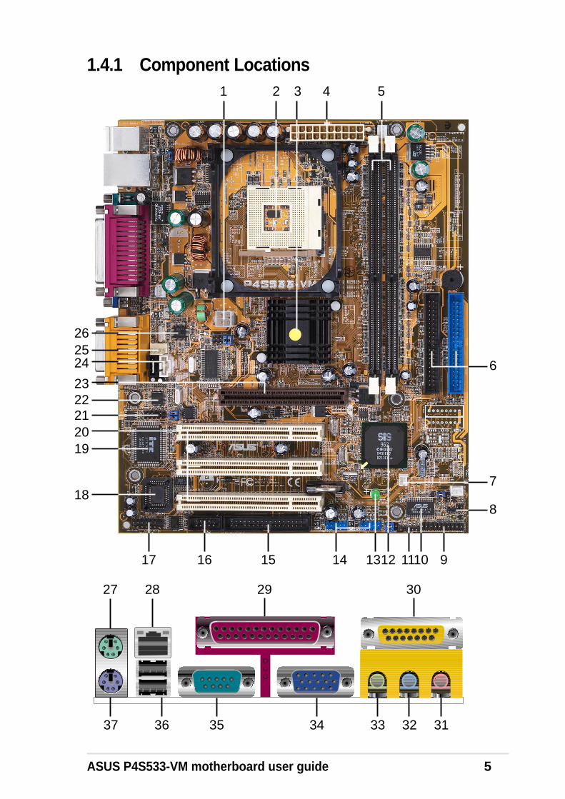
1.4 Motherboard ComponentsBefore installing the P4S533-VM motherboard, take time to familiarize yourselfwith its configuration: understanding the motherboard makes upgrading easy.Sufficient knowledge of specifications prevents accidental damage.
ASUS P4S533-VM motherboard user guide 5
1.4.1 Component Locations2 3 4 5
1216
2019
1
18
13
21
26
15 14 9111017
24 6
8
7
25
2223
27 28 29 30
3132333537 36 34


Chapter 2
Hardware information

ASUS P4S533-VM motherboard
ASUS P4S533-VM motherboard user guide 7
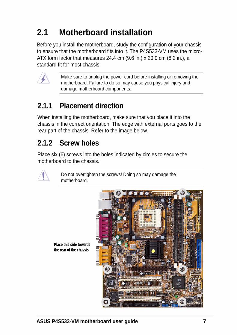
2.1 Motherboard installationBefore you install the motherboard, study the configuration of your chassisto ensure that the motherboard fits into it. The P4S533-VM uses the micro-ATX form factor that measures 24.4 cm (9.6 in.) x 20.9 cm (8.2 in.), astandard fit for most chassis.
Do not overtighten the screws! Doing so may damage themotherboard.
2.1.1 Placement directionWhen installing the motherboard, make sure that you place it into thechassis in the correct orientation. The edge with external ports goes to therear part of the chassis. Refer to the image below.
2.1.2 Screw holesPlace six (6) screws into the holes indicated by circles to secure themotherboard to the chassis.
Make sure to unplug the power cord before installing or removing themotherboard. Failure to do so may cause you physical injury anddamage motherboard components.
Place this side towardsthe rear of the chassis

8 Chapter 2: Hardware information
2.2 Motherboard layout
The audio and LAN features are optional. These components aregrayed out in the above motherboard layout.
FLOPPY1PANEL1
IR_CON1
BATTERY1
CD1
CPU_FAN1
SiS651HOST/Memory
Controller
PS/2T: MouseB: Keyboard
GA
ME
_AU
DIO
MicIn
LineOut
LineIn
AUX1
IDE_LED1
USBPWR_34
P4S533-VM
®
SMARTCON1
FP
_AU
DIO
1
MODEM
ITE
870
7FS
uper
I/O
2MbitFlashBIOS
PCI Slot 1
ATX Power Connector
SE
C_I
DE
1
Bottom:USB1USB2
Top:RJ-45
DD
R D
IMM
2 (6
4/72
bit,
184
-pin
mod
ule)
2 3
DD
R D
IMM
1 (6
4/72
bit,
184
-pin
mod
ule)
0 1
Accelerated Graphics Port(AGP)
USBPWR_12
SiS962LMuTLOL
MediaI/0
SPDIF_OUT1
ATX12V1
AudioCodec
RTL8201
ASUSMozart
SIRQ1
CHA_FAN1
CLRTC1
20.9cm (8.2in)
24.4
cm (
9.6i
n)
Sock
et 478COM1
PA
RA
LL
EL
PO
RT
VGA
PCI Slot 2
PCI Slot 3
PR
I_ID
E1
BUZZER1
SB_PWR1
FSJ1
FP_LO_SWR
COM2
USBPWR_56USB_56USB_34
FP_LO_SWL
ASUS P4S533-VM motherboard user guide 9
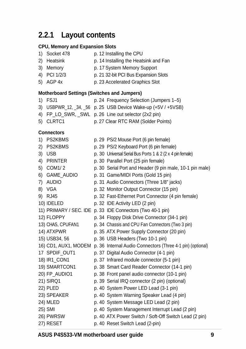
2.2.1 Layout contentsCPU, Memory and Expansion Slots1) Socket 478 p. 12 Installing the CPU2) Heatsink p. 14 Installing the Heatsink and Fan3) Memory p. 17 System Memory Support4) PCI 1/2/3 p. 21 32-bit PCI Bus Expansion Slots5) AGP 4x p. 23 Accelerated Graphics Slot
Motherboard Settings (Switches and Jumpers)1) FSJ1 p. 24 Frequency Selection (Jumpers 1–5)3) USBPWR_12, _34, _56 p. 25 USB Device Wake-up (+5V / +5VSB)4) FP_LO_SWR, _SWL p. 26 Line out selector (2x2 pin)5) CLRTC1 p. 27 Clear RTC RAM (Solder Points)
Connectors1) PS2KBMS p. 29 PS/2 Mouse Port (6 pin female)2) PS2KBMS p. 29 PS/2 Keyboard Port (6 pin female)3) USB p. 30 Universal Serial Bus Ports 1 & 2 (2 x 4 pin female)4) PRINTER p. 30 Parallel Port (25 pin female)5) COM1/ 2 p. 30 Serial Port and Header (9 pin male, 10-1 pin male)6) GAME_AUDIO p. 31 Game/MIDI Ports (Gold 15 pin)7) AUDIO p. 31 Audio Connectors (Three 1/8” jacks)8) VGA p. 32 Monitor Output Connector (15 pin)9) RJ45 p. 32 Fast-Ethernet Port Connector (4 pin female)10) IDELED p. 32 IDE Activity LED (2 pin)11) PRIMARY / SEC. IDE p. 33 IDE Connectors (Two 40-1 pin)12) FLOPPY p. 34 Floppy Disk Drive Connector (34-1 pin)13) CHAS, CPUFAN1 p. 34 Chassis and CPU Fan Connectors (Two 3 pin)14) ATXPWR p. 35 ATX Power Supply Connector (20 pin)15) USB34, 56 p. 36 USB Headers (Two 10-1 pin)16) CD1, AUX1, MODEM p. 36 Internal Audio Connectors (Three 4-1 pin) (optional)17 SPDIF_OUT1 p. 37 Digital Audio Connector (4-1 pin)18) IR1_CON1 p. 37 Infrared module connector (5-1 pin)19) SMARTCON1 p. 38 Smart Card Reader Connector (14-1 pin)20) FP_AUDIO1 p. 38 Front panel audio connector (10-1 pin)21) SIRQ1 p. 39 Serial IRQ connector (2 pin) (optional)22) PLED p. 40 System Power LED Lead (3-1 pin)23) SPEAKER p. 40 System Warning Speaker Lead (4 pin)24) MLED p. 40 System Message LED Lead (2 pin)25) SMI p. 40 System Management Interrupt Lead (2 pin)26) PWRSW p. 40 ATX Power Switch / Soft-Off Switch Lead (2 pin)27) RESET p. 40 Reset Switch Lead (2-pin)

10 Chapter 2: Hardware information
2.3 Before you proceedTake note of the following precautions before you install motherboardcomponents or change any motherboard settings.
1. Unplug the power cord from the wall socket before touching anycomponent.
2. Use a grounded wrist strap or touch a safely grounded object or to ametal object, such as the power supply case, before handlingcomponents to avoid damaging them due to static electricity.
3. Hold components by the edges and do not to touch the ICs on them.
4. Whenever you uninstall any component, place it on a groundedantistatic pad or in the bag that came with the component.
5. Before you install or remove any component, ensure that theATX power supply is switched off or the power cord isdetached from the power supply. Failure to do so may causesevere damage to the motherboard, peripherals, and/orcomponents.

ASUS P4S533-VM motherboard user guide 11
2.4 Central Processing Unit (CPU)
2.4.1 OverviewThe motherboard comes with a surface mount 478-pin Zero InsertionForce (ZIF) socket. This socket is specifically designed for the Intel®
Pentium® 4 478/Northwood Processor.
The Intel Pentium 4 Processor in the 478-pin package uses the Flip-ChipPin Grid Array 2 (FC-PGA2) package technology, and includes the Intel®
NetBurst™ micro-architecture. The Intel NetBurst micro-architecturefeatures the hyper-pipelined technology, rapid execution engine, 400MHzsystem bus, and execution trace cache. Together, these attributes improvesystem performance by allowing higher processor frequencies, fasterexecution of integer instructions, and a data transfer rate of 3.2GB/s.
Note in the illustration that the CPU has a gold triangular mark on onecorner. This mark indicates the processor Pin 1 that should match aspecific corner of the CPU socket.
Incorrect installation of the CPU into the socket may bend the pins andseverely damage the CPU!
Gold Mark
12 Chapter 2: Hardware information
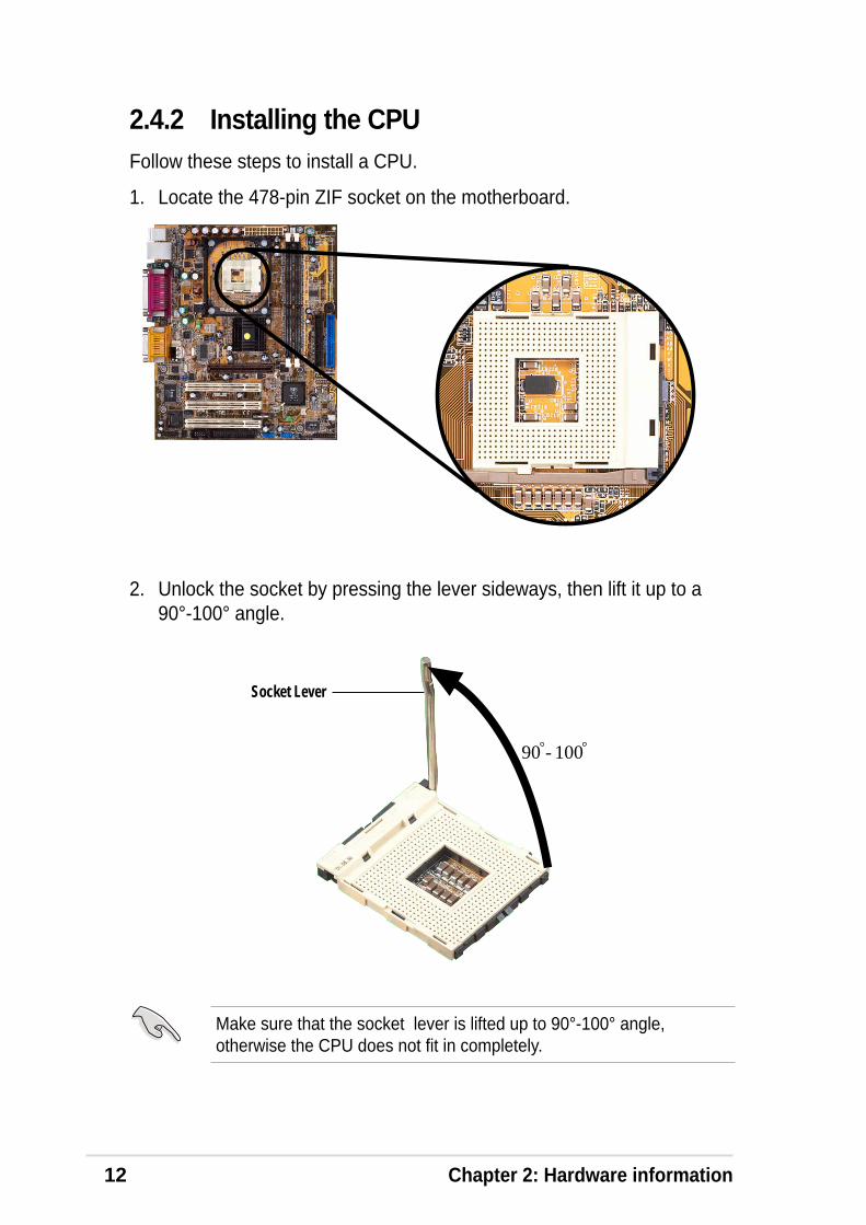
2.4.2 Installing the CPUFollow these steps to install a CPU.
1. Locate the 478-pin ZIF socket on the motherboard.
2. Unlock the socket by pressing the lever sideways, then lift it up to a90°-100° angle.
Make sure that the socket lever is lifted up to 90°-100° angle,otherwise the CPU does not fit in completely.
Socket Lever
90 - 100

ASUS P4S533-VM motherboard user guide 13
3. Position the CPU above the socket such that its marked cornermatches the base of the socket lever.
4. Carefully insert the CPU into the socket until it fits in place.
The CPU fits only in one correct orientation. DO NOT force the CPUinto the socket to prevent bending the pins and damaging the CPU!
5. When the CPU is in place, press it firmly on the socket while you pushdown the socket lever to secure the CPU. The lever clicks on the sidetab to indicate that it is locked.
Gold Mark

14 Chapter 2: Hardware information
2.4.3 Installing the heatsink and fanThe Intel® Pentium® 4 478/Northwood Processor requires a speciallydesigned heatsink and fan assembly to ensure optimum thermal conditionand performance.
The retention module base is already installed on the motherboardupon purchase.
You do not have to remove the retention module base when installingthe CPU or installing other motherboard components.
Follow these steps to install the CPU heatsink and fan.
1. Place the heatsink on top of the installed CPU, making sure that theheatsink fits properly on the retention module base.
When you buy a boxed Intel Pentium 4 478/Northwood Processor, thepackage includes the heatsink, fan, and retention mechanism.
In case you buy a CPU separately, make sure that you use only Intelcertified heatsink and fan.
Your boxed Intel Pentium 4 478/Northwood Processor package shouldcome with installation instructions for the CPU, heatsink, and theretention mechanism. If the instructions in this section do not match theCPU documentation, follow the latter.
Retention Module Base
CPU Heatsink

ASUS P4S533-VM motherboard user guide 15
2. Position the fan with the retention mechanism on top of the heatsink.Align and snap the four hooks of the retention mechanism to the holeson each corner of the module base.
Keep the retention locks lifted upward while fitting the retentionmechanism to the module base.
Make sure that the fan and retention mechanism assembly perfectlyfits the heatsink and module base, otherwise you cannot snap thehooks into the holes.
Retention Hole
Retention Hook Snappedto the Retention Hole
Retention Lock
16 Chapter 2: Hardware information
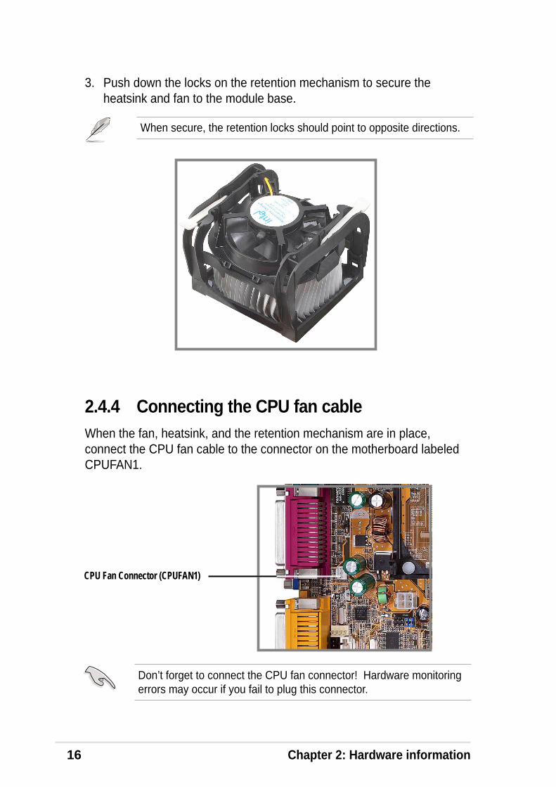
2.4.4 Connecting the CPU fan cableWhen the fan, heatsink, and the retention mechanism are in place,connect the CPU fan cable to the connector on the motherboard labeledCPUFAN1.
3. Push down the locks on the retention mechanism to secure theheatsink and fan to the module base.
When secure, the retention locks should point to opposite directions.
CPU Fan Connector (CPUFAN1)
Don’t forget to connect the CPU fan connector! Hardware monitoringerrors may occur if you fail to plug this connector.

ASUS P4S533-VM motherboard user guide 17
2.5 System memory
2.5.1 OverviewThe motherboard comes with two Double Data Rate (DDR) Dual InlineMemory Module (DIMM) sockets. These sockets support up to 2GBsystem memory using 184-pin unbuffered non-ECC PC2700/2100/1600DIMMs.
A DDR DIMM is keyed with a notch so that it fits in only one direction.DO NOT force a DIMM into a socket to avoid damaging the DIMM.
The DDR SDRAM technology evolved from the mainstream PC66, PC100,PC133 memory known as Single Data Rate (SDR) SDRAM. DDR memoryhowever, has the ability to perform two data operations in one clock cycle,thus providing twice the throughput of SDR memory.
P4S533-VM
®
P4S533-VM 184-Pin DDR DIMM Sockets
80 Pins
104 Pins
A DDR DIMM has the same physical dimensions as an SDR DIMM, but ithas a 184-pin footprint compared to the 168-pin of the SDR DIMM. Also, aDDR DIMM is single notched while an SDR DIMM is double notched.Therefore, a DDR DIMM is not backward compatible with SDR, and shouldbe installed only in a socket specially designed for DDR DIMMs.
DDR Data Transfer Rate DDR Base Frequency
2.7 GB/s 166MHz
2.1 GB/s 133MHz
1.6 GB/s 100MHz
18 Chapter 2: Hardware information
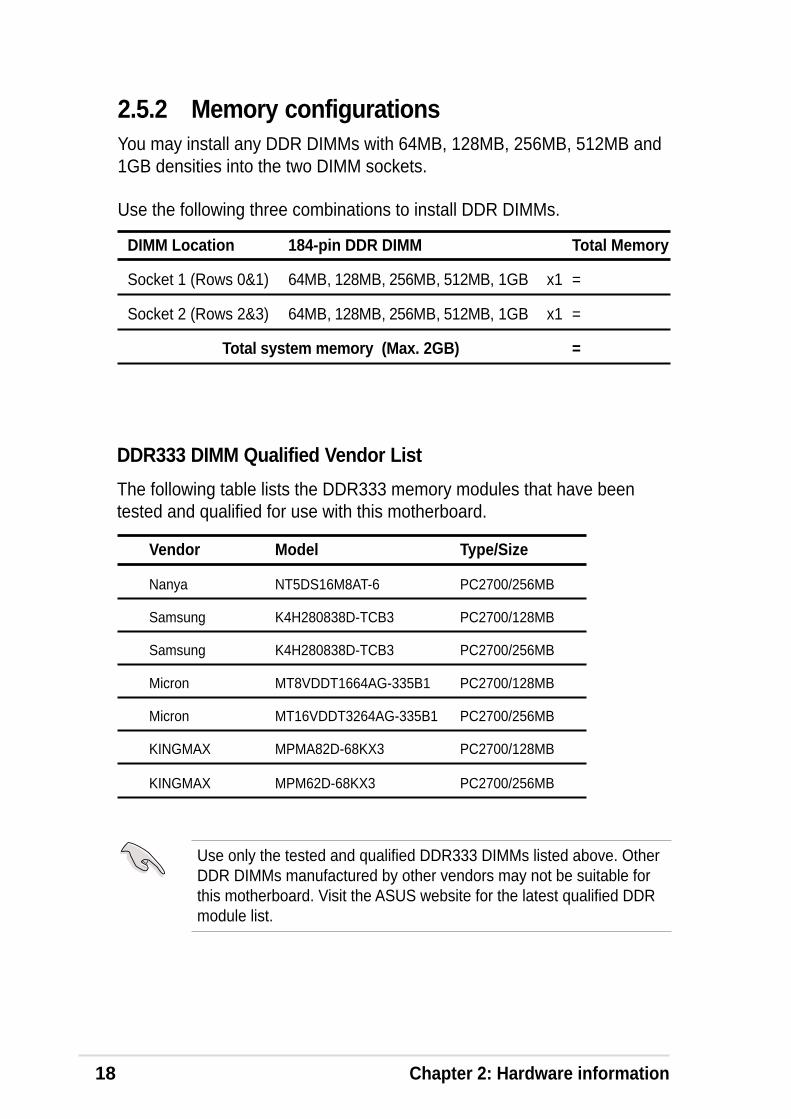
2.5.2 Memory configurationsYou may install any DDR DIMMs with 64MB, 128MB, 256MB, 512MB and1GB densities into the two DIMM sockets.
Use the following three combinations to install DDR DIMMs.
DIMM Location 184-pin DDR DIMM Total Memory
Socket 1 (Rows 0&1) 64MB, 128MB, 256MB, 512MB, 1GB x1 =
Socket 2 (Rows 2&3) 64MB, 128MB, 256MB, 512MB, 1GB x1 =
Total system memory (Max. 2GB) =
Vendor Model Type/Size
Nanya NT5DS16M8AT-6 PC2700/256MB
Samsung K4H280838D-TCB3 PC2700/128MB
Samsung K4H280838D-TCB3 PC2700/256MB
Micron MT8VDDT1664AG-335B1 PC2700/128MB
Micron MT16VDDT3264AG-335B1 PC2700/256MB
KINGMAX MPMA82D-68KX3 PC2700/128MB
KINGMAX MPM62D-68KX3 PC2700/256MB
DDR333 DIMM Qualified Vendor List
The following table lists the DDR333 memory modules that have beentested and qualified for use with this motherboard.
Use only the tested and qualified DDR333 DIMMs listed above. OtherDDR DIMMs manufactured by other vendors may not be suitable forthis motherboard. Visit the ASUS website for the latest qualified DDRmodule list.
ASUS P4S533-VM motherboard user guide 19
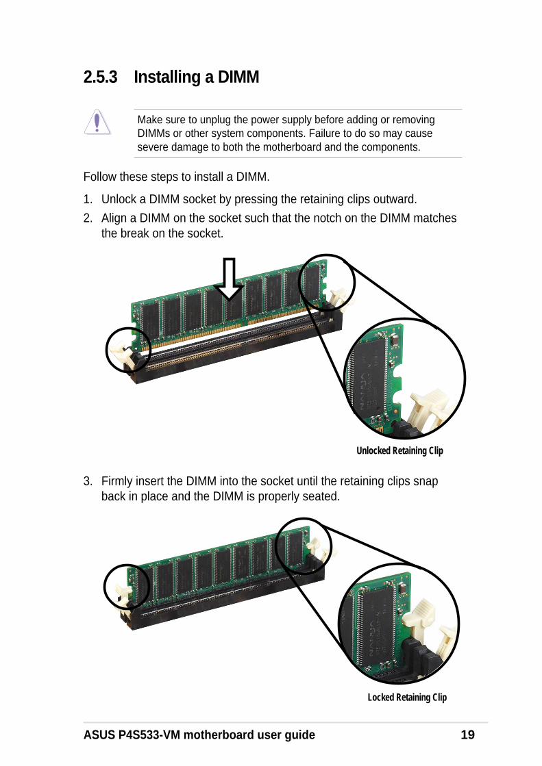
3. Firmly insert the DIMM into the socket until the retaining clips snapback in place and the DIMM is properly seated.
Locked Retaining Clip
2.5.3 Installing a DIMM
Make sure to unplug the power supply before adding or removingDIMMs or other system components. Failure to do so may causesevere damage to both the motherboard and the components.
Follow these steps to install a DIMM.
1. Unlock a DIMM socket by pressing the retaining clips outward.
2. Align a DIMM on the socket such that the notch on the DIMM matchesthe break on the socket.
Unlocked Retaining Clip
20 Chapter 2: Hardware information
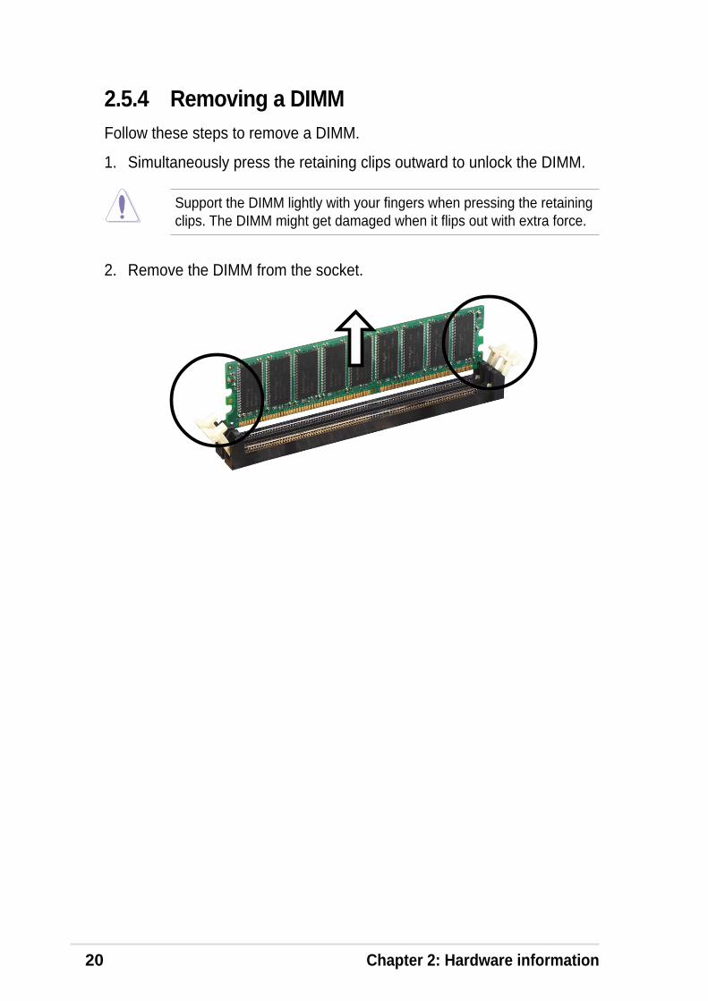
2.5.4 Removing a DIMMFollow these steps to remove a DIMM.
1. Simultaneously press the retaining clips outward to unlock the DIMM.
Support the DIMM lightly with your fingers when pressing the retainingclips. The DIMM might get damaged when it flips out with extra force.
2. Remove the DIMM from the socket.
ASUS P4S533-VM motherboard user guide 21
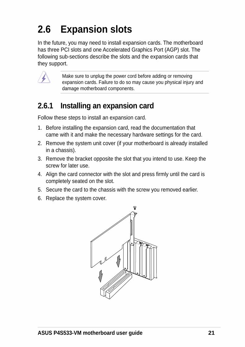
2.6 Expansion slotsIn the future, you may need to install expansion cards. The motherboardhas three PCI slots and one Accelerated Graphics Port (AGP) slot. Thefollowing sub-sections describe the slots and the expansion cards thatthey support.
2.6.1 Installing an expansion cardFollow these steps to install an expansion card.
1. Before installing the expansion card, read the documentation thatcame with it and make the necessary hardware settings for the card.
2. Remove the system unit cover (if your motherboard is already installedin a chassis).
3. Remove the bracket opposite the slot that you intend to use. Keep thescrew for later use.
4. Align the card connector with the slot and press firmly until the card iscompletely seated on the slot.
5. Secure the card to the chassis with the screw you removed earlier.
6. Replace the system cover.
Make sure to unplug the power cord before adding or removingexpansion cards. Failure to do so may cause you physical injury anddamage motherboard components.
22 Chapter 2: Hardware information
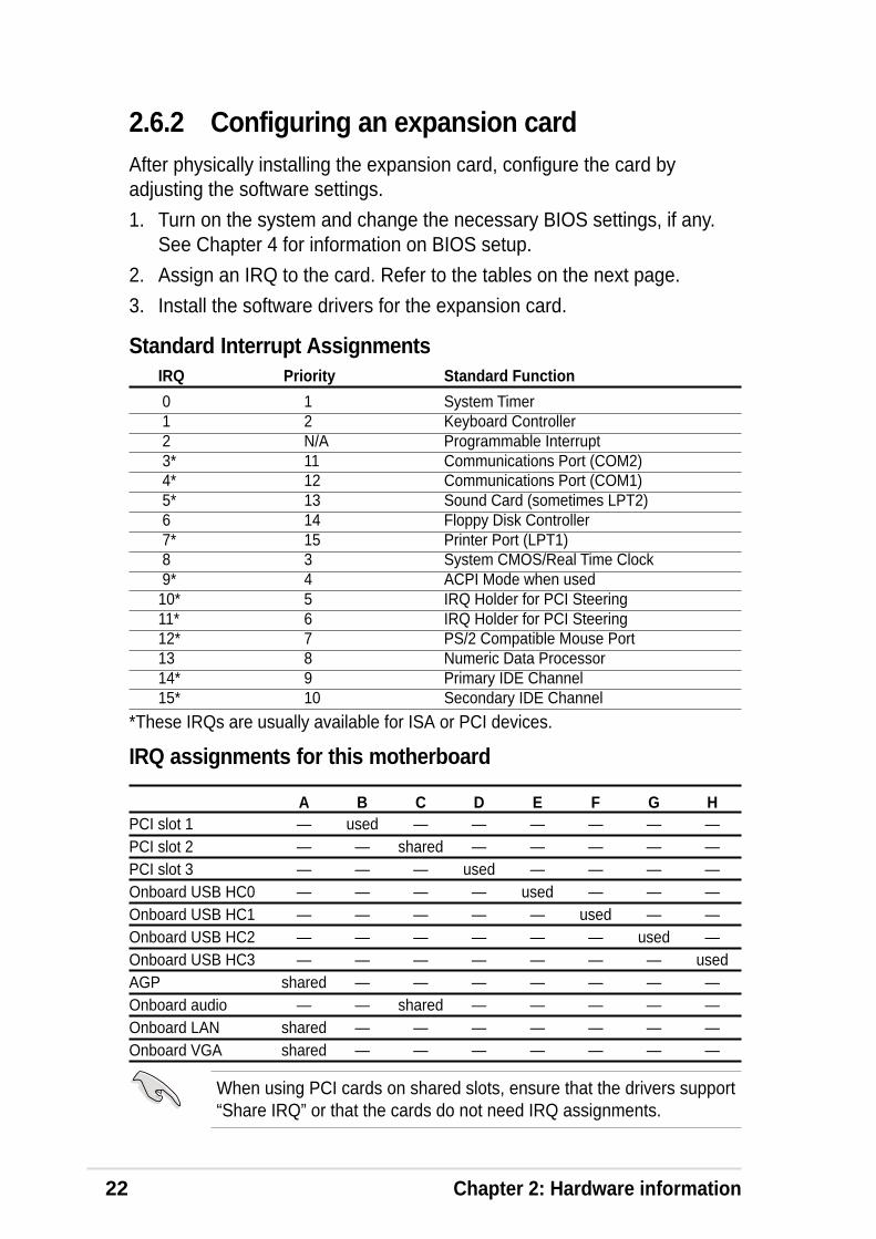
Standard Interrupt AssignmentsIRQ Priority Standard Function
0 1 System Timer 1 2 Keyboard Controller 2 N/A Programmable Interrupt 3* 11 Communications Port (COM2) 4* 12 Communications Port (COM1) 5* 13 Sound Card (sometimes LPT2) 6 14 Floppy Disk Controller 7* 15 Printer Port (LPT1) 8 3 System CMOS/Real Time Clock 9* 4 ACPI Mode when used10* 5 IRQ Holder for PCI Steering11* 6 IRQ Holder for PCI Steering12* 7 PS/2 Compatible Mouse Port13 8 Numeric Data Processor14* 9 Primary IDE Channel15* 10 Secondary IDE Channel
*These IRQs are usually available for ISA or PCI devices.
IRQ assignments for this motherboard
A B C D E F G HPCI slot 1 — used — — — — — —PCI slot 2 — — shared — — — — —PCI slot 3 — — — used — — — —Onboard USB HC0 — — — — used — — —Onboard USB HC1 — — — — — used — —Onboard USB HC2 — — — — — — used —Onboard USB HC3 — — — — — — — usedAGP shared — — — — — — —Onboard audio — — shared — — — — —Onboard LAN shared — — — — — — —Onboard VGA shared — — — — — — —
When using PCI cards on shared slots, ensure that the drivers support“Share IRQ” or that the cards do not need IRQ assignments.
2.6.2 Configuring an expansion cardAfter physically installing the expansion card, configure the card byadjusting the software settings.
1. Turn on the system and change the necessary BIOS settings, if any.See Chapter 4 for information on BIOS setup.
2. Assign an IRQ to the card. Refer to the tables on the next page.
3. Install the software drivers for the expansion card.
ASUS P4S533-VM motherboard user guide 23
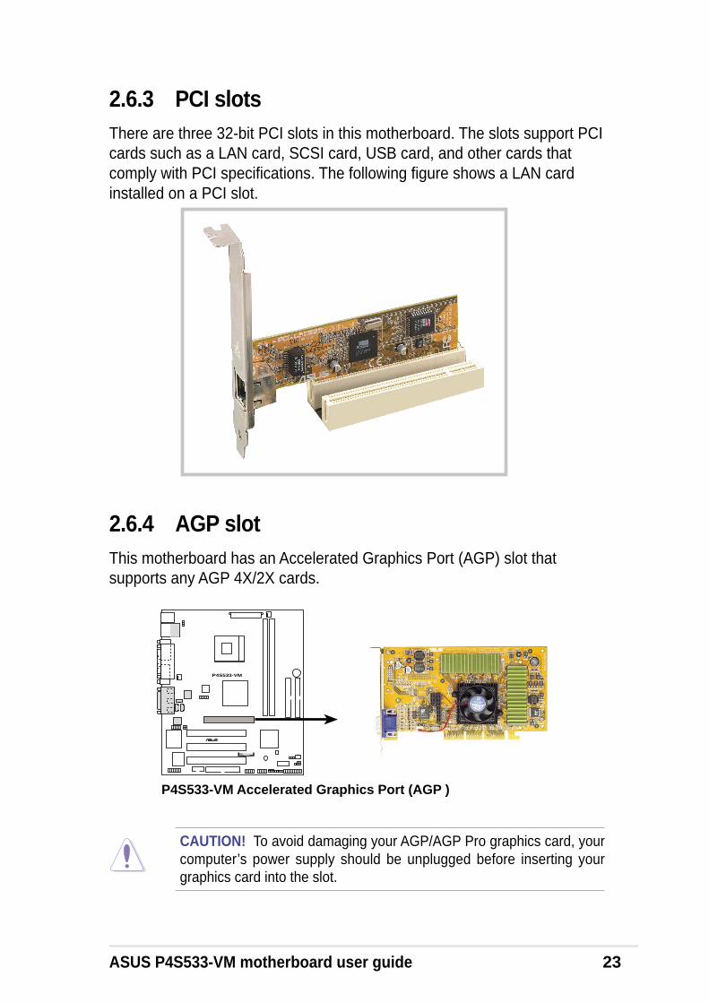
2.6.3 PCI slotsThere are three 32-bit PCI slots in this motherboard. The slots support PCIcards such as a LAN card, SCSI card, USB card, and other cards thatcomply with PCI specifications. The following figure shows a LAN cardinstalled on a PCI slot.
2.6.4 AGP slotThis motherboard has an Accelerated Graphics Port (AGP) slot thatsupports any AGP 4X/2X cards.
P4S533-VM
®
P4S533-VM Accelerated Graphics Port (AGP )
CAUTION! To avoid damaging your AGP/AGP Pro graphics card, yourcomputer’s power supply should be unplugged before inserting yourgraphics card into the slot.

24 Chapter 2: Hardware information
P4S533-VM
®
P4S533-VM CPUExternal Frequency Selection
FSJ1
CPU 100MHzDDR 200MHz
1 100MHz266MHz
1 100MHz333MHz
1
CPU 133MHzDDR 200MHz
1 133MHz266MHz
1 133MHz333MHz
1
(Default)
1. CPU External Frequency Selection (FSJ1 Jumpers 1–5)This option tells the clock generator which frequency to send to the CPUand DRAM. This allows the selection of the CPU’s External frequency (orBUS Clock). The BUS Clock multiplied by the Frequency Multiple equalsthe CPU’s Internal frequency (the advertised CPU speed).
WARNING! Set the CPU AND DRAM frequencies only to therecommended settings. Frequencies other than the recommended CPUbus frequencies are not guaranteed to be stable. Overclocking theprocessor is not recommended, as it may result in a slower speed.
2.7 JumpersThe jumpers on the motherboard allow you to change some featuresettings to suit your customized system configuration.
Before changing any FSJ or jumper setting, make sure to read thejumper descriptions and setting requirements in this section.
Motherboard Frequency Settings (FSJ Jumpers)The motherboard frequency is adjusted through the FSJ jumpers.
Frequency Table MHz FSJ1 CPU DRAM 5 4 3 2 1 100 200 [OFF] [OFF] [OFF] [OFF] [ON] 100 266 [OFF] [OFF] [OFF] [ON] [ON] 100 333 [OFF] [ON] [OFF] [OFF] [ON] 133 200 [ON] [OFF] [ON] [OFF] [ON] 133 266 [ON] [OFF] [ON] [ON] [OFF] 133 333 [ON] [OFF] [ON] [ON] [ON]

ASUS P4S533-VM motherboard user guide 25
2. USB Device Wake-Up (USBPWR_12, _34, _56)The default setting, [1-2] (+5V) disables the USB wake-up feature.Reset these jumpers to pins [2-3] (+5VSB) to wake up the computerusing USB devices.
The USB device wake-up feature requires a power supply that canprovide at least 1A on the +5VSB lead. If this requirement is not met,the system does not power up. The total current consumed must NOTexceed the power supply capability (+5VSB) whether under normalcondition or in sleep mode. Also note that ONLY USB +5VSB cansupport S3 resume function.
P4S533-VM
®
P4S533-VM USB Device Wake Up
USBPWR_12
+5VSB
32
+5V(Default)
12
+5V(Default)
1 2
+5VSB
32
USBPWR_56USBPWR_34
Setting +5V (default) +5VSBUSBPWR_12 [1-2] [2-3]USBPWR_34 [1-2] [2-3]USBPWR_56 [1-2] [2-3]
CAUTION! It is advisable not to increase the CPU voltage excessivelyto prevent premature failure and/or poor CPU performance.

26 Chapter 2: Hardware information
P4S533-VM
®
P4S533-VM Internal Line Out Connectors
FP_LO_SWLFP_LO_SWR
BLO
LF
LOL
BLO
RF
LOR
3. Line out selector (FP_LO_SWR, FP_LO_SWL) (on audio models only)
By default, these jumpers are shorted (jumper caps on) to route thesignal from the audio controller to the rear panel Line Out jack to makeit available for audio out devices like speakers or headphones.
If you connect the Intel Front Panel audio cable to the FP_Audioconnector (see page 38 for the location), remove the caps from thesejumpers to allow automatic switching of audio signals between the rearpanel Line Out jack and the audio cable.

ASUS P4S533-VM motherboard user guide 27
P4S533-VM
®
P4S533-VM Clear RTC RAM Setting
Short solder pointsto Clear CMOS
CLRTC1
4. Clear RTC RAM (CLRTC1)These solder points allow you to clear the Real Time Clock (RTC) RAMin CMOS. You can clear the CMOS memory of date, time, and systemsetup parameters by erasing the CMOS RTC RAM data. The RAMdata in CMOS, that include system setup information such as systempasswords, is powered by the onboard button cell battery.
To erase the RTC RAM:
1. Turn OFF the computer and unplug the power cord.2. Remove the motherboard battery.3. Short the solder points using a delicate metal implement like a
paper-clip.4. Replace the battery.5. Plug the power cord and turn ON the computer.6. Hold down the <Del> key during the boot process and enter BIOS
setup to re-enter data.

28 Chapter 2: Hardware information

ASUS P4S533-VM motherboard user guide 29
2.8 ConnectorsThis section describes and illustrates the internal connectors on themotherboard.
IMPORTANT! Ribbon cables should always be connected with the redstripe to Pin 1 in the connector scoket.
1. PS/2 Mouse Port (Green, 6-pin PS2KBMS)The system automatically directs IRQ12 to the PS/2 mouse if one isdetected. If no mouse is detected, IRQ12 become available to expansioncards. See PS/2 Mouse Function Control in 4.4 Advanced Menu.
2. PS/2 Keyboard Port (Purple, 6-pin PS2KBMS)This connection is for a standard keyboard using an PS/2 plug (mini DIN).This connector does not allow standard AT size (large DIN) keyboardplugs. You may use a DIN to mini DIN adapter on standard AT keyboards.
PS/2 Mouse (6-pin female)
WARNING! Some pins are used for connectors or power sources. Theseare clearly distinguished from jumpers in the Motherboard Layout. Placingjumper caps over these connector pins will cause damage to yourmotherboard.
PS/2 Keyboard (6-pin female)

30 Chapter 2: Hardware information
3. Universal Serial Bus Ports 1 and 2 (Black, Two x 4-pin USB)Four USB ports are available for connecting USB devices.
5. Serial Port and Header (Teal/Turquoise 9-pin COM1, 10-1 pin COM2)One serial port can be used for pointing devices, printers or other serialdevices. An onboard header supports a serial bracket. To enable theseports, see Onboard Serial Port 1 in 4.4.2 I/O Device Configuration forthe settings.
4. Parallel Port (Burgundy 25-pin PRINTER)You can enable the parallel port and choose the IRQ through OnboardParallel Port (see 4.4.2 I/O Device Configuration).
Universal Serial Bus (USB)
COM 1Serial Port (9-pin male)
Parallel (Printer) Port (25-pin female)
NOTE! Serial printers must be connected to the serial port.
ASUS P4S533-VM motherboard user guide 31
MicLine InLine Out1/8" Stereo Audio Connectors
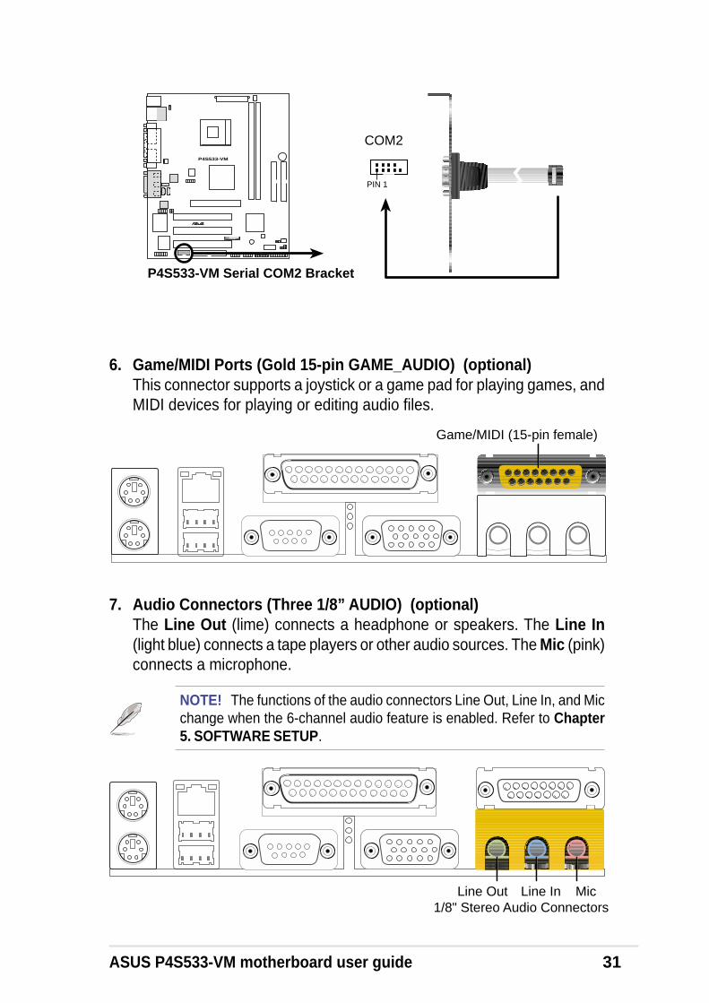
7. Audio Connectors (Three 1/8” AUDIO) (optional)The Line Out (lime) connects a headphone or speakers. The Line In(light blue) connects a tape players or other audio sources. The Mic (pink)connects a microphone.
NOTE! The functions of the audio connectors Line Out, Line In, and Micchange when the 6-channel audio feature is enabled. Refer to Chapter5. SOFTWARE SETUP.
Game/MIDI (15-pin female)
6. Game/MIDI Ports (Gold 15-pin GAME_AUDIO) (optional)This connector supports a joystick or a game pad for playing games, andMIDI devices for playing or editing audio files.
P4S533-VM
®
P4S533-VM Serial COM2 Bracket
PIN 1
COM2

32 Chapter 2: Hardware information
Some pins are used for connectors or power sources. These areclearly distinguished from jumpers in the Motherboard Layout. Placingjumper caps over these connector pins will cause damage to yourmotherboard.
10. IDE Activity LED (2-pin IDELED)This connector supplies power to the hard disk activity LED. The read orwrite activities of any device connected to the primary or secondary IDEconnector cause this LED to light up.
P4S533-VM
®
P4S533-VM IDE Activity LED
TIP: If the case-mounted LED does notlight, try reversing the 2-pin plug.
IDE_LED1
RJ-45
9. Fast-Ethernet Port Connector (RJ45) (optional)This RJ45 connector is located on top of the USB Ports 0 & 1. The RJ45supports connectivity for local area networks.
8. Monitor Output Connector (Blue 15 pin VGA)This connector supports a VGA-compatible device.
VGA Monitor (15-pin female)
ASUS P4S533-VM motherboard user guide 33
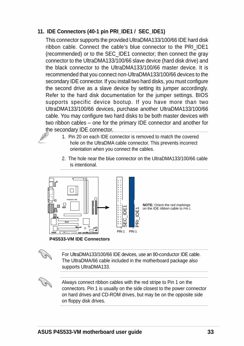
11. IDE Connectors (40-1 pin PRI_IDE1 / SEC_IDE1)This connector supports the provided UltraDMA133/100/66 IDE hard diskribbon cable. Connect the cable’s blue connector to the PRI_IDE1(recommended) or to the SEC_IDE1 connector; then connect the grayconnector to the UltraDMA133/100/66 slave device (hard disk drive) andthe black connector to the UltraDMA133/100/66 master device. It isrecommended that you connect non-UltraDMA133/100/66 devices to thesecondary IDE connector. If you install two hard disks, you must configurethe second drive as a slave device by setting its jumper accordingly.Refer to the hard disk documentation for the jumper settings. BIOSsupports specific device bootup. If you have more than twoUltraDMA133/100/66 devices, purchase another UltraDMA133/100/66cable. You may configure two hard disks to be both master devices withtwo ribbon cables – one for the primary IDE connector and another forthe secondary IDE connector.
1. Pin 20 on each IDE connector is removed to match the coveredhole on the UltraDMA cable connector. This prevents incorrectorientation when you connect the cables.
2. The hole near the blue connector on the UltraDMA133/100/66 cableis intentional.
For UltraDMA133/100/66 IDE devices, use an 80-conductor IDE cable.The UltraDMA/66 cable included in the motherboard package alsosupports UltraDMA133.
P4S533-VM
®
P4S533-VM IDE Connectors
NOTE: Orient the red markingson the IDE ribbon cable to PIN 1
SE
C_I
DE
1
PIN 1
PR
I_ID
E1
PIN 1
Always connect ribbon cables with the red stripe to Pin 1 on theconnectors. Pin 1 is usually on the side closest to the power connectoron hard drives and CD-ROM drives, but may be on the opposite sideon floppy disk drives.
34 Chapter 2: Hardware information
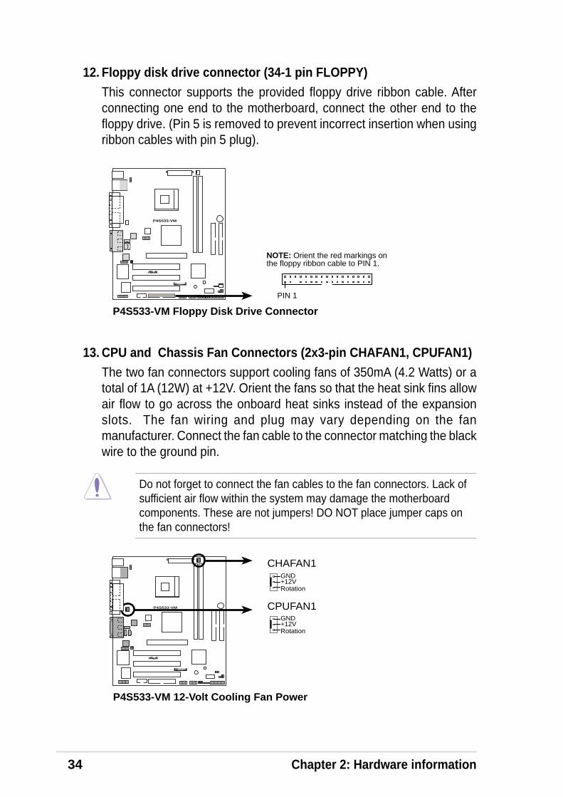
12. Floppy disk drive connector (34-1 pin FLOPPY)This connector supports the provided floppy drive ribbon cable. Afterconnecting one end to the motherboard, connect the other end to thefloppy drive. (Pin 5 is removed to prevent incorrect insertion when usingribbon cables with pin 5 plug).
P4S533-VM
®
NOTE: Orient the red markings onthe floppy ribbon cable to PIN 1.
P4S533-VM Floppy Disk Drive Connector
PIN 1
13. CPU and Chassis Fan Connectors (2x3-pin CHAFAN1, CPUFAN1)The two fan connectors support cooling fans of 350mA (4.2 Watts) or atotal of 1A (12W) at +12V. Orient the fans so that the heat sink fins allowair flow to go across the onboard heat sinks instead of the expansionslots. The fan wiring and plug may vary depending on the fanmanufacturer. Connect the fan cable to the connector matching the blackwire to the ground pin.
Do not forget to connect the fan cables to the fan connectors. Lack ofsufficient air flow within the system may damage the motherboardcomponents. These are not jumpers! DO NOT place jumper caps onthe fan connectors!
P4S533-VM 12-Volt Cooling Fan Power
CPUFAN1GND
Rotation+12V
CHAFAN1GND
Rotation+12V
P4S533-VM
®
ASUS P4S533-VM motherboard user guide 35
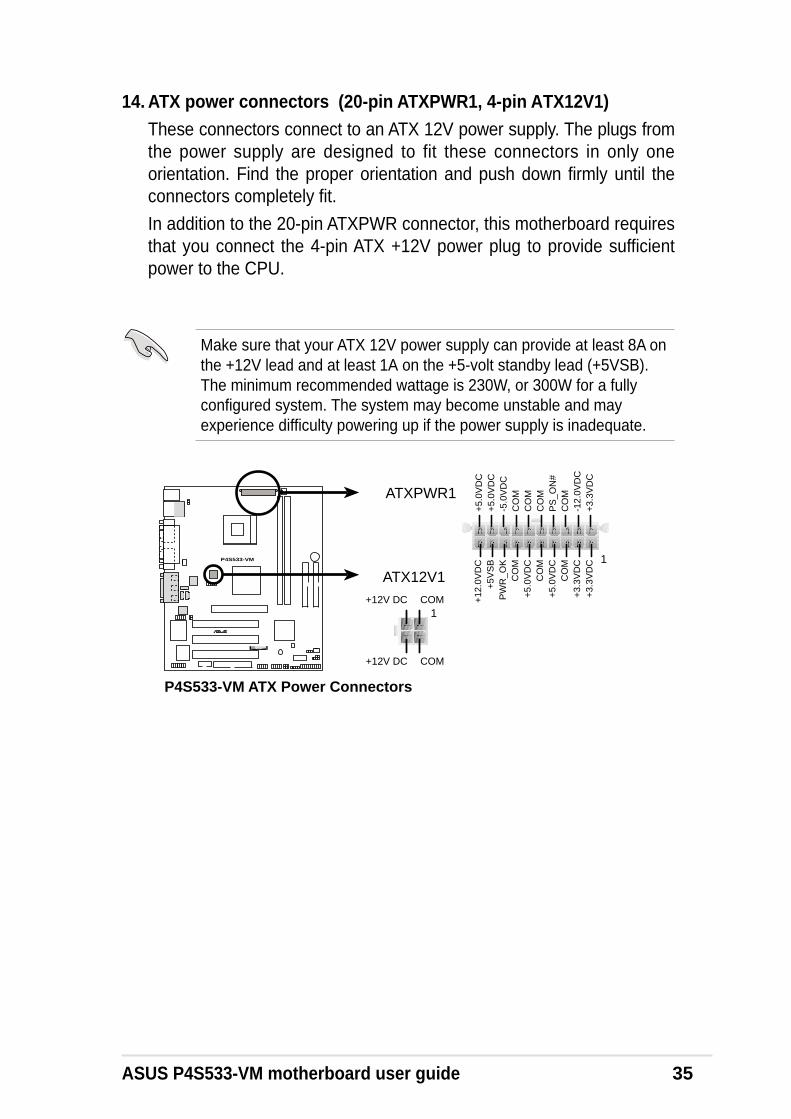
14. ATX power connectors (20-pin ATXPWR1, 4-pin ATX12V1)These connectors connect to an ATX 12V power supply. The plugs fromthe power supply are designed to fit these connectors in only oneorientation. Find the proper orientation and push down firmly until theconnectors completely fit.
In addition to the 20-pin ATXPWR connector, this motherboard requiresthat you connect the 4-pin ATX +12V power plug to provide sufficientpower to the CPU.
Make sure that your ATX 12V power supply can provide at least 8A onthe +12V lead and at least 1A on the +5-volt standby lead (+5VSB).The minimum recommended wattage is 230W, or 300W for a fullyconfigured system. The system may become unstable and mayexperience difficulty powering up if the power supply is inadequate.
P4S533-VM
®
P4S533-VM ATX Power Connectors
ATX12V1
+12V DC COM
+12V DC COM1
ATXPWR1
1
+3.
3VD
C-1
2.0V
DC
CO
MP
S_O
N#
CO
MC
OM
CO
M-5
.0V
DC
+5.
0VD
C+
5.0V
DC
PW
R_O
K
+12
.0V
DC
+3.
3VD
C+
3.3V
DC
CO
M
+5.
0VD
CC
OM
+5.
0VD
C
CO
M
+5V
SB
36 Chapter 2: Hardware information
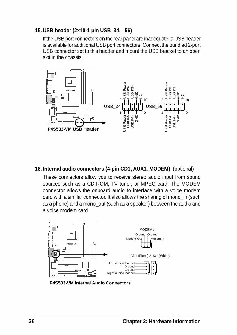
16. Internal audio connectors (4-pin CD1, AUX1, MODEM) (optional)
These connectors allow you to receive stereo audio input from soundsources such as a CD-ROM, TV tuner, or MPEG card. The MODEMconnector allows the onboard audio to interface with a voice modemcard with a similar connector. It also allows the sharing of mono_in (suchas a phone) and a mono_out (such as a speaker) between the audio anda voice modem card.
P4S533-VM
®
P4S533-VM Internal Audio Connectors
CD1 (Black) AUX1 (White)
MODEM1
Right Audio Channel
Left Audio Channel
GroundGround
Modem-Out
Ground
Modem-In
Ground
15. USB header (2x10⁻¹ pin USB_34, _56)If the USB port connectors on the rear panel are inadequate, a USB headeris available for additional USB port connectors. Connect the bundled 2-portUSB connector set to this header and mount the USB bracket to an openslot in the chassis.
P4S533-VM
®
P4S533-VM USB Header
USB_34
US
B P
4-U
SB
P4+
US
B P
ower
GN
D
1
US
B P
3-U
SB
P3+
US
B P
ower
GN
DN
C
2
9
10
USB_56
US
B P
4-U
SB
P4+
US
B P
ower
GN
D
1
US
B P
3-U
SB
P3+
US
B P
ower
GN
DN
C
2
9
10

ASUS P4S533-VM motherboard user guide 37
17. Digital audio connector (4-1 pin SPDIF_OUT1) (optional)
This connector connects an S/PDIF audio module that allows digitalinstead of analog sound output. Connect one end of the audio cable tothe S/PDIF Out connector on the motherboard, and the other end to theS/PDIF module.
P4S533-VM
®
P4S533-VM Digital Audio Connector
+5V
SP
DIF
OU
TG
ND
SPDIF_OUT1
The S/PDIF module is not included in the motherboard package.
18. Infrared module connector (5-1 pin IR_CON1)This connector supports an optional wireless transmitting and receivinginfrared module. This module mounts to a small opening on systemchassis that support this feature. You must also configure the UART2Use As parameter in BIOS to set UART2 for use with IR. See section“4.4.2 I/O Device Configuration” for details.
Use the five pins as shown in Back View and connect a ribbon cable fromthe module to the motherboard SIR connector according to the pindefinitions.
P4S533-VM
®
P4S533-VM Infrared Module Connector
Back View
+5VIRTX
IRRX(NC)GND
Front View
IR_CON1
+5V
IRR
X
IRT
X
GN
D
1
38 Chapter 2: Hardware information
P4S533-VM
®
P4S533-VM Intel Panel Connector
FP_AUDIO1
BO
UT
_L
MIC
2
LOU
T_R
LOU
T_LNC
MIC
PW
R+
5VA
AG
ND
_A
1
BO
UT
_R
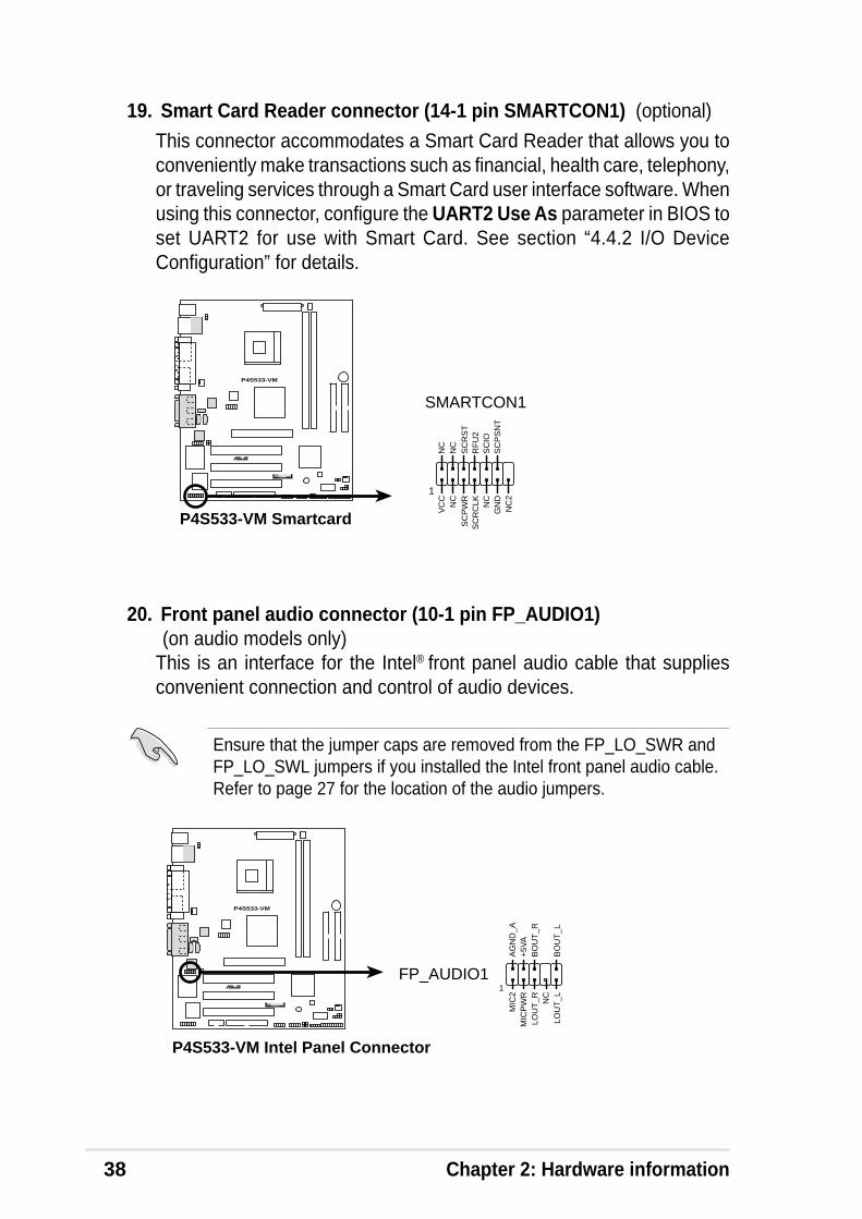
20. Front panel audio connector (10-1 pin FP_AUDIO1) (on audio models only)
This is an interface for the Intel® front panel audio cable that suppliesconvenient connection and control of audio devices.
19. Smart Card Reader connector (14-1 pin SMARTCON1) (optional)
This connector accommodates a Smart Card Reader that allows you toconveniently make transactions such as financial, health care, telephony,or traveling services through a Smart Card user interface software. Whenusing this connector, configure the UART2 Use As parameter in BIOS toset UART2 for use with Smart Card. See section “4.4.2 I/O DeviceConfiguration” for details.
P4S533-VM
®
P4S533-VM Smartcard
SMARTCON1
1
NC
SC
PW
R
NC
RF
U2
NC
2
VC
C
GN
DS
CIO
SC
PS
NT
NC
SC
RC
LK NC
SC
RS
T
Ensure that the jumper caps are removed from the FP_LO_SWR andFP_LO_SWL jumpers if you installed the Intel front panel audio cable.Refer to page 27 for the location of the audio jumpers.

ASUS P4S533-VM motherboard user guide 39
P4S533-VM
®
P4S533-VM SIRQ1 Connector
SIRQ1
SERIRQGND
21. Serial IRQ connector (2 pin SIRQ1) (optional)
This connector supports the serial IRQ cable. This cable is required bysome PCI cards like those with PCMCIA function.
40 Chapter 2: Hardware information
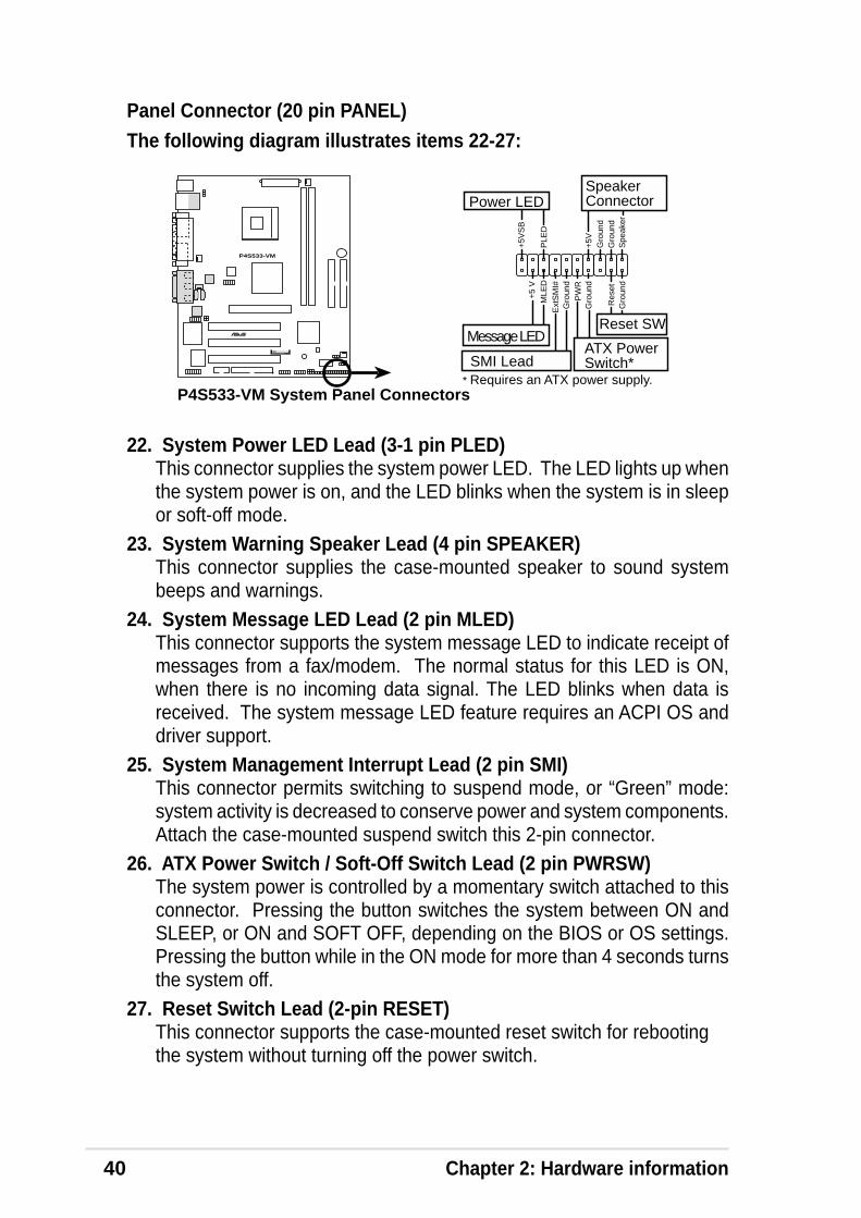
Panel Connector (20 pin PANEL)The following diagram illustrates items 22-27:
P4S533-VM
®
P4S533-VM System Panel Connectors* Requires an ATX power supply.
PLE
D
Gro
und
MLE
D
PW
R
+5V
SB
+5V Spe
aker
SpeakerConnectorPower LED
Gro
und
+5
V
Reset SW
SMI Lead
Message LED
Ext
SM
I#
Gro
und
Res
etG
roun
dG
roun
d
ATX PowerSwitch*
22. System Power LED Lead (3-1 pin PLED)This connector supplies the system power LED. The LED lights up whenthe system power is on, and the LED blinks when the system is in sleepor soft-off mode.
23. System Warning Speaker Lead (4 pin SPEAKER)This connector supplies the case-mounted speaker to sound systembeeps and warnings.
24. System Message LED Lead (2 pin MLED)This connector supports the system message LED to indicate receipt ofmessages from a fax/modem. The normal status for this LED is ON,when there is no incoming data signal. The LED blinks when data isreceived. The system message LED feature requires an ACPI OS anddriver support.
25. System Management Interrupt Lead (2 pin SMI)This connector permits switching to suspend mode, or “Green” mode:system activity is decreased to conserve power and system components.Attach the case-mounted suspend switch this 2-pin connector.
26. ATX Power Switch / Soft-Off Switch Lead (2 pin PWRSW)The system power is controlled by a momentary switch attached to thisconnector. Pressing the button switches the system between ON andSLEEP, or ON and SOFT OFF, depending on the BIOS or OS settings.Pressing the button while in the ON mode for more than 4 seconds turnsthe system off.
27. Reset Switch Lead (2-pin RESET)This connector supports the case-mounted reset switch for rebootingthe system without turning off the power switch.
Chapter 3
Powering up

ASUS P4S533-VM motherboard

ASUS P4S533-VM motherboard user guide 41
3.1 Starting up for the first time1. After making all the connections, replace the system case cover.
2. Be sure that all switches are off.
3. Connect the power cord to the power connector at the back of thesystem chassis.
4. Connect the power cord to a power outlet that is equipped with a surgeprotector.
5. Turn on the devices in the following order:a. Monitorb. External SCSI devices (starting with the last device on the chain)c. System power (if you are using an ATX power supply, you need to
switch on the power supply as well as press the ATX power switchon the front of the chassis).
6. After applying power, the power LED on the system front panel caselights up. For ATX power supplies, the system LED lights up when youpress the ATX power switch. If your monitor complies with “green”standards or if it has a “power standby” feature, the monitor LED maylight up or switch between orange and green after the system LEDturns on. The system then runs the power-on tests. While the tests arerunning, the BIOS beeps or additional messages appear on thescreen. If you do not see anything within 30 seconds from the time youturned on the power, the system may have failed a power-on test.Check the jumper settings and connections or call your retailer forassistance.
Award BIOS Beep Codes
Beep Meaning
One short beep when No error during POSTdisplaying logo
Long beeps in an endless loop No DRAM installed or detected
One long beep followed by Video card not found or video cardthree short beeps memory bad
High frequency beeps when CPU overheated;system is working System running at a lower frequency
7. At power on, hold down <Delete> to enter BIOS Setup. Follow theinstructions in Chapter 4.
You will not hear the BIOS beeps when the ASUS POST Reporter isenabled. You will hear the vocal POST messages instead.

42 Chapter 3: Powering up
3.3 Powering off the computerYou must first exit the operating system and shut down the system beforeswitching off the power. For ATX power supplies, you can press the ATXpower switch after exiting or shutting down the operating system. If youuse Windows 95/98/2000/XP, click the Start button, click Shut Down, thenclick the OK button to shut down the computer. The power supply shouldturn off after Windows shuts down.
The message “You can now safely turn off your computer” does notappear when shutting down with ATX power supplies.
Chapter 4
BIOS setup

ASUS P4S533-VM motherboard

ASUS P4S533-VM motherboard user guide 43
4.1 Managing and updating your BIOS
4.1.1 Using the computer system for the first timeIt is recommended that you save a copy of the original motherboard BIOSalong with a Flash Memory Writer utility (AFLASH.EXE) to a bootablefloppy disk in case you need to reinstall the BIOS later. AFLASH.EXE is aFlash Memory Writer utility that updates the BIOS by uploading a newBIOS file to the programmable flash ROM on the motherboard. This fileworks only in DOS mode. To determine the BIOS version of yourmotherboard, check the last four numbers of the code displayed on theupper left-hand corner of your screen during bootup. Larger numbersrepresent a newer BIOS file.
1. Type FORMAT A:/S at the DOS prompt to create a bootable systemdisk. DO NOT copy AUTOEXEC.BAT and CONFIG.SYS to the disk.
2. Type COPY D:\AFLASH\AFLASH.EXE A:\ (assuming D is yourCD-ROM drive) to copy AFLASH.EXE to the boot disk you created.
BIOS setup must specify “Floppy” as the first item in the bootsequence.
4. In DOS mode, type A:\AFLASH <Enter> to run AFLASH.
If the word “unknown” appears after Flash Memory:, the memory chipis either not programmable or is not supported by the ACPI BIOS andtherefore, cannot be programmed by the Flash Memory Writer utility.
AFLASH works only in DOS mode. It does not work in the DOS promptwithin Windows and does not work with certain memory drivers thatmay be loaded when you boot from the hard drive. It is recommendedthat you reboot using a floppy disk.
3. Reboot the computer from the floppy disk.
44 Chapter 4: BIOS Setup
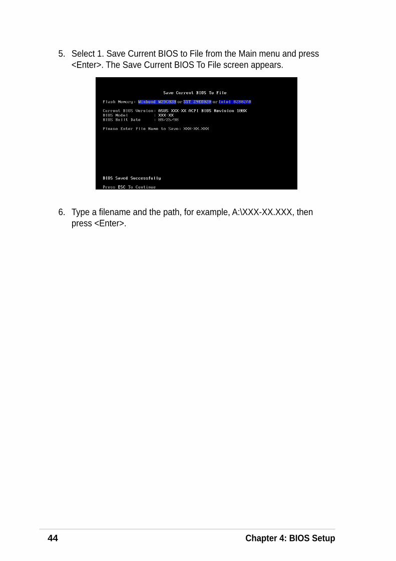
5. Select 1. Save Current BIOS to File from the Main menu and press<Enter>. The Save Current BIOS To File screen appears.
6. Type a filename and the path, for example, A:\XXX-XX.XXX, thenpress <Enter>.
ASUS P4S533-VM motherboard user guide 45
1. Download an updated ASUS BIOS file from the Internet (see the ASUSContact Information on page x for details) and save to the boot floppydisk you created earlier.
2. Boot from the floppy disk.
3. At the “A:\” prompt, type AFLASH and then press <Enter>.
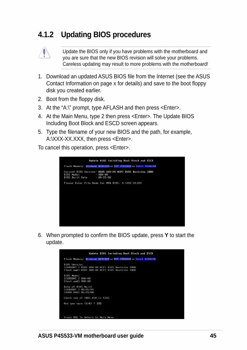
4. At the Main Menu, type 2 then press <Enter>. The Update BIOSIncluding Boot Block and ESCD screen appears.
5. Type the filename of your new BIOS and the path, for example,A:\XXX-XX.XXX, then press <Enter>.
To cancel this operation, press <Enter>.
6. When prompted to confirm the BIOS update, press Y to start theupdate.
Update the BIOS only if you have problems with the motherboard andyou are sure that the new BIOS revision will solve your problems.Careless updating may result to more problems with the motherboard!
4.1.2 Updating BIOS procedures
46 Chapter 4: BIOS Setup
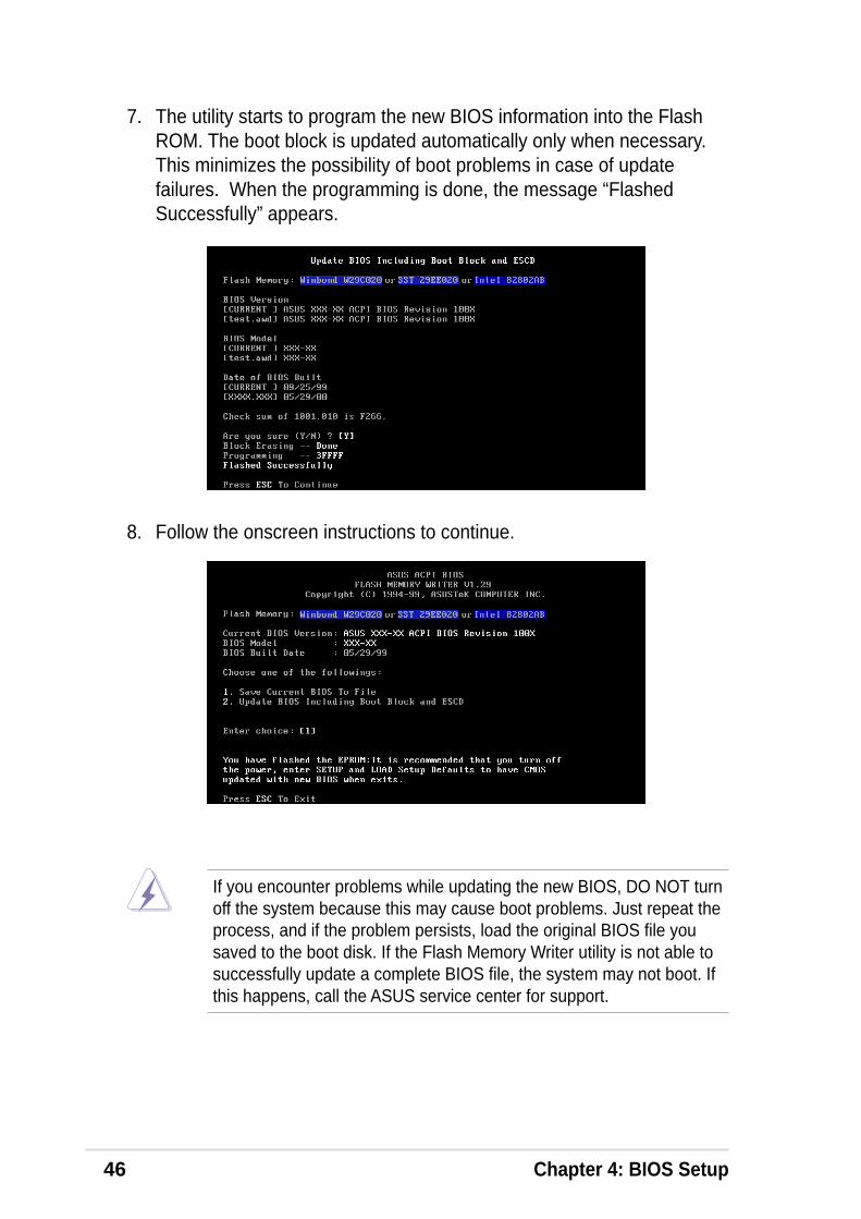
7. The utility starts to program the new BIOS information into the FlashROM. The boot block is updated automatically only when necessary.This minimizes the possibility of boot problems in case of updatefailures. When the programming is done, the message “FlashedSuccessfully” appears.
8. Follow the onscreen instructions to continue.
If you encounter problems while updating the new BIOS, DO NOT turnoff the system because this may cause boot problems. Just repeat theprocess, and if the problem persists, load the original BIOS file yousaved to the boot disk. If the Flash Memory Writer utility is not able tosuccessfully update a complete BIOS file, the system may not boot. Ifthis happens, call the ASUS service center for support.
ASUS P4S533-VM motherboard user guide 47
4.2 BIOS Setup programThis motherboard supports a programmable EEPROM that you canupdate using the provided utility described in section “4.1 Managing andupdating your BIOS.”
Use the BIOS Setup program when you are installing a motherboard,reconfiguring your system, or prompted to “Run Setup”. This sectionexplains how to configure your system using this utility.
Even if you are not prompted to use the Setup program, you may want tochange the configuration of your computer in the future. For example, youmay want to enable the security password Feature or make changes to thepower management settings. This requires you to reconfigure your systemusing the BIOS Setup program so that the computer can recognize thesechanges and record them in the CMOS RAM of the EEPROM.
The EEPROM on the motherboard stores the Setup utility. When you startup the computer, the system provides you with the opportunity to run thisprogram. Press <Delete> during the Power-On Self Test (POST) to enterthe Setup utility, otherwise, POST continues with its test routines.
If you wish to enter Setup after POST, restart the system by pressing<Ctrl> + <Alt> + <Delete>, or by pressing the reset button on the systemchassis. You can also restart by turning the system off and then back on.Do this last option only if the first two failed.
The Setup program is designed to make it as easy to use as possible. It isa menu-driven program, which means you can scroll through the varioussub-menus and make your selections among the predetermined choices.
Because the BIOS software is constantly being updated, the followingBIOS setup screens and descriptions are for reference purposes only,and may not exactly match what you see on your screen.
48 Chapter 4: BIOS Setup
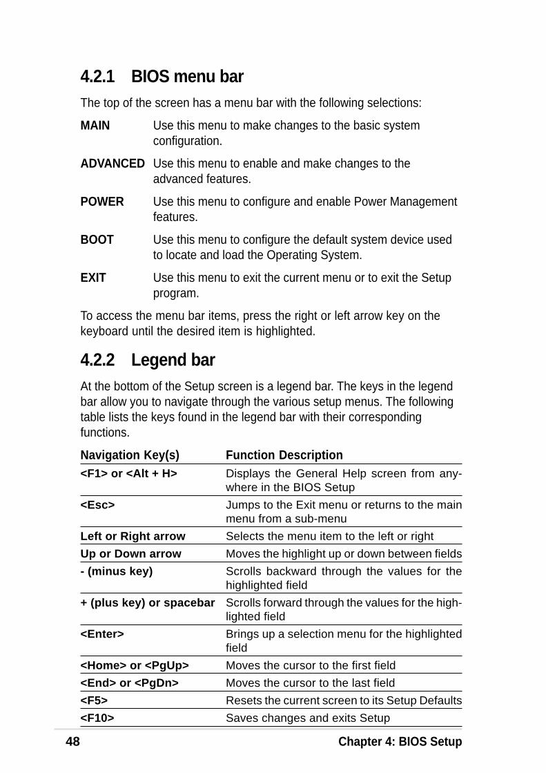
4.2.1 BIOS menu barThe top of the screen has a menu bar with the following selections:
MAIN Use this menu to make changes to the basic systemconfiguration.
ADVANCED Use this menu to enable and make changes to theadvanced features.
POWER Use this menu to configure and enable Power Managementfeatures.
BOOT Use this menu to configure the default system device usedto locate and load the Operating System.
EXIT Use this menu to exit the current menu or to exit the Setupprogram.
To access the menu bar items, press the right or left arrow key on thekeyboard until the desired item is highlighted.
4.2.2 Legend barAt the bottom of the Setup screen is a legend bar. The keys in the legendbar allow you to navigate through the various setup menus. The followingtable lists the keys found in the legend bar with their correspondingfunctions.
Navigation Key(s) Function Description<F1> or <Alt + H> Displays the General Help screen from any-
where in the BIOS Setup
<Esc> Jumps to the Exit menu or returns to the mainmenu from a sub-menu
Left or Right arrow Selects the menu item to the left or right
Up or Down arrow Moves the highlight up or down between fields
- (minus key) Scrolls backward through the values for thehighlighted field
+ (plus key) or spacebar Scrolls forward through the values for the high-lighted field
<Enter> Brings up a selection menu for the highlightedfield
<Home> or <PgUp> Moves the cursor to the first field
<End> or <PgDn> Moves the cursor to the last field
<F5> Resets the current screen to its Setup Defaults
<F10> Saves changes and exits Setup

ASUS P4S533-VM motherboard user guide 49
General helpIn addition to the Item Specific Help window, the BIOS setup program alsoprovides a General Help screen. You may launch this screen from anymenu by simply pressing <F1> or the <Alt> + <H> combination. TheGeneral Help screen lists the legend keys and their correspondingfunctions.
Saving changes and exiting the Setup programSee “4.7 Exit Menu” for detailed information on saving changes and exitingthe setup program.
Scroll barWhen a scroll bar appears to the right of a help window, it indicates thatthere is more information to be displayed that will not fit in the window. Use<PgUp> and <PgDn> or the up and down arrow keys to scroll through theentire help document. Press <Home> to display the first page, press<End> to go to the last page. To exit the help window, press <Enter> or<Esc>.
Sub-menuNote that a right pointer symbol (as shown on theleft) appears to the left of certain fields. This pointerindicates that you can display a sub-menu from thisfield. A sub-menu contains additional options for afield parameter. To display a sub-menu, move thehighlight to the field and press <Enter>. The sub-menu appears. Use the legend keys to enter valuesand move from field to field within a sub-menu asyou would within a menu. Use the <Esc> key toreturn to the main menu.
Take some time to familiarize yourself with the legend keys and theircorresponding functions. Practice navigating through the various menusand sub-menus. If you accidentally make unwanted changes to any of thefields, use the set default hot key <F5> to load the Setup default values.While moving around through the Setup program, note that explanationsappear in the Item Specific Help window located to the right of each menu.This window displays the help text for the currently highlighted field.
50 Chapter 4: BIOS Setup
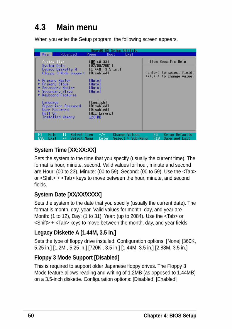
System Time [XX:XX:XX]Sets the system to the time that you specify (usually the current time). Theformat is hour, minute, second. Valid values for hour, minute and secondare Hour: (00 to 23), Minute: (00 to 59), Second: (00 to 59). Use the <Tab>or <Shift> + <Tab> keys to move between the hour, minute, and secondfields.
System Date [XX/XX/XXXX]Sets the system to the date that you specify (usually the current date). Theformat is month, day, year. Valid values for month, day, and year areMonth: (1 to 12), Day: (1 to 31), Year: (up to 2084). Use the <Tab> or<Shift> + <Tab> keys to move between the month, day, and year fields.
Legacy Diskette A [1.44M, 3.5 in.]Sets the type of floppy drive installed. Configuration options: [None] [360K,5.25 in.] [1.2M , 5.25 in.] [720K , 3.5 in.] [1.44M, 3.5 in.] [2.88M, 3.5 in.]
Floppy 3 Mode Support [Disabled]This is required to support older Japanese floppy drives. The Floppy 3Mode feature allows reading and writing of 1.2MB (as opposed to 1.44MB)on a 3.5-inch diskette. Configuration options: [Disabled] [Enabled]
4.3 Main menuWhen you enter the Setup program, the following screen appears.

ASUS P4S533-VM motherboard user guide 51
4.3.1 Primary & Secondary Master/Slave
Type [Auto]Select [Auto] to automatically detect an IDE hard disk drive. If automaticdetection is successful, Setup automatically fills in the correct values forthe remaining fields on this sub-menu. If automatic detection fails, this maybe because the hard disk drive is too old or too new. If the hard disk wasalready formatted on an older system, Setup may detect incorrectparameters. In these cases, select [User Type HDD] to manually enter theIDE hard disk drive parameters. Refer to the next section for details.
Before attempting to configure a hard disk drive, make sure you havethe correct configuration information supplied by the drivemanufacturer. Incorrect settings may cause the system to fail torecognize the installed hard disk.

52 Chapter 4: BIOS Setup
If no drive is installed or if you are removing a drive and not replacing it,select [None].
Other options for the Type field are:
[CD-ROM] - for IDE CD-ROM drives
[LS-120] - for LS-120 compatible floppy disk drives
[ZIP] - for ZIP-compatible disk drives
[MO] - for IDE magneto optical disk drives
[Other ATAPI Device] - for IDE devices not listed here
After making your selections on this sub-menu, press the <Esc> key toreturn to the Main menu. When the Main menu appears, the hard diskdrive field displays the size for the hard disk drive that you configured.
[User Type HDD]
After entering the IDE hard disk drive information into BIOS, use a diskutility, such as FDISK, to partition and format new IDE hard disk drives.This is necessary so that you can write or read data from the hard disk.Make sure to set the partition of the Primary IDE hard disk drives toactive.
Manually enter the number of cylinders, heads and sectors per track forthe drive. Refer to the drive documentation or on the drive label for thisinformation.
ASUS P4S533-VM motherboard user guide 53
Translation Method [LBA]Select the hard disk drive type in this field. When Logical Block Addressing(LBA) is enabled, the 28-bit addressing of the hard drive is used withoutregard for cylinders, heads, or sectors. Note that LBA Mode is necessaryfor drives with more than 504MB storage capacity. Configuration options:[LBA] [LARGE] [Normal] [Match Partition Table] [Manual]
CylindersThis field configures the number of cylinders. Refer to the drivedocumentation to determine the correct value. To make changes to thisfield, set the Type field to [User Type HDD] and the Translation Methodfield to [Manual].
HeadThis field configures the number of read/write heads. Refer to the drivedocumentation to determine the correct value. To make changes to thisfield, set the Type field to [User Type HDD] and the Translation Methodfield to [Manual].
SectorThis field configures the number of sectors per track. Refer to the drivedocumentation to determine the correct value. To make changes to thisfield, set the Type field to [User Type HDD] and the Translation Methodfield to [Manual].
CHS CapacityThis field shows the drive’s maximum CHS capacity as calculated by theBIOS based on the drive information you entered.
Maximum LBA CapacityThis field shows the drive’s maximum LBA capacity as calculated by theBIOS based on the drive information you entered.
Multi-Sector Transfers [Maximum]This option automatically sets the number of sectors per block to thehighest number that the drive supports. Note that when this field isautomatically configured, the set value may not always be the fastestvalue for the drive. You may also manually configure this field. Refer to thedocumentation that came with the hard drive to determine the optimumvalue and set it manually. To make changes to this field, set the Type fieldto [User Type HDD]. Configuration options: [Disabled] [2 Sectors] [4Sectors] [8 Sectors] [16 Sectors] [32 Sectors] [Maximum]

54 Chapter 4: BIOS Setup
SMART Monitoring [Disabled]This field allows you to enable or disable the S.M.A.R.T. (Self-Monitoring,Analysis and Reporting Technology) system that utilizes internal hard diskdrive monitoring technology. This parameter is normally disabled becausethe resources used in the SMART monitoring feature may decreasesystem performance. Configuration options: [Disabled] [Enabled]
PIO Mode [4]This option lets you set a PIO (Programmed Input/Output) mode for theIDE device. Modes 0 through 4 provide successive increase inperformance. Configuration options: [0] [1] [2] [3] [4]
Ultra DMA Mode [Disabled]Ultra DMA capability allows improved transfer speeds and data integrity forcompatible IDE devices. Set to [Disabled] to suppress Ultra DMAcapability. To make changes to this field, set the Type field to [User TypeHDD]. Configuration options: [0] [1] [2] [3] [4] [5] [6] [Disabled]

ASUS P4S533-VM motherboard user guide 55
4.3.2 Keyboard Features
Boot Up NumLock Status [On]This field enables users to activate the Number Lock function upon systemboot. Configuration options: [Off] [On]
Keyboard Auto-Repeat Rate [6/Sec]This controls the speed at which the system registers repeated keystrokes.Options range from 6 to 30 characters per second. Configuration options:[6/Sec] [8/Sec] [10/Sec] [12/Sec] [15/Sec] [20/Sec] [24/Sec] [30/Sec]
Keyboard Auto-Repeat Delay [1/4 Sec]This field sets the time interval for displaying the first and secondcharacters. Configuration options: [1/4 Sec] [1/2 Sec] [3/4 Sec] [1 Sec]

56 Chapter 4: BIOS Setup
Language [English]This field displays the BIOS language version.
Supervisor Password [Disabled] / User Password [Disabled]These fields allow you to set passwords. To set a password, highlight theappropriate field and press <Enter>. Type in a password then press<Enter>. You can type up to eight alphanumeric characters. Symbols andother characters are ignored. To confirm the password, type the passwordagain and press <Enter>. The password is now set to [Enabled]. Thispassword allows full access to the BIOS Setup menus. To clear thepassword, highlight this field and press <Enter>. The same dialog box asabove appears. Press <Enter>. The password is set to [Disabled].
A note about passwordsThe BIOS Setup program allows you to specify passwords in the Mainmenu. The passwords control access to the BIOS during system startup.Passwords are not case sensitive, meaning, passwords typed in eitheruppercase or lowercase letters are accepted. The BIOS Setup programallows you to specify two different passwords: a Supervisor password anda User password. If you did not set a Supervisor password, anyone canaccess the BIOS Setup program. If you did, the Supervisor password isrequired to enter the BIOS Setup program and to gain full access to theconfiguration fields.
Halt On [All Errors]This field specifies the types of errors that will cause the system to halt.Configuration options: [All Errors] [No Error] [All but Keyboard] [All butDisk] [All but Disk/Keyboard]
Installed Memory [XXX MB]This field automatically displays the amount of conventional memorydetected by the system during the boot process.
Main menu items continued...
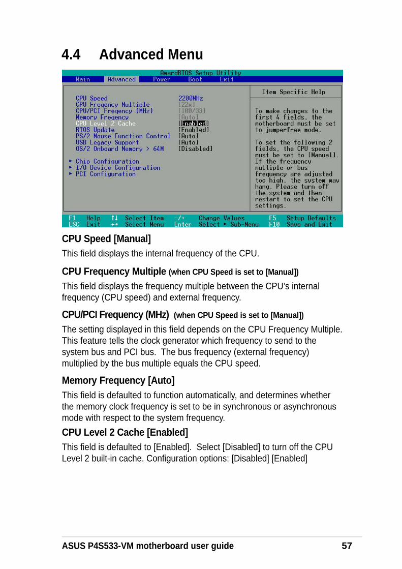
ASUS P4S533-VM motherboard user guide 57
4.4 Advanced Menu
CPU Frequency Multiple (when CPU Speed is set to [Manual])
This field displays the frequency multiple between the CPU’s internalfrequency (CPU speed) and external frequency.
CPU/PCI Frequency (MHz) (when CPU Speed is set to [Manual])
The setting displayed in this field depends on the CPU Frequency Multiple.This feature tells the clock generator which frequency to send to thesystem bus and PCI bus. The bus frequency (external frequency)multiplied by the bus multiple equals the CPU speed.
Memory Frequency [Auto]This field is defaulted to function automatically, and determines whetherthe memory clock frequency is set to be in synchronous or asynchronousmode with respect to the system frequency.
CPU Level 2 Cache [Enabled]This field is defaulted to [Enabled]. Select [Disabled] to turn off the CPULevel 2 built-in cache. Configuration options: [Disabled] [Enabled]
CPU Speed [Manual]This field displays the internal frequency of the CPU.
58 Chapter 4: BIOS Setup
BIOS Update [Enabled]This field functions as an update loader integrated into the BIOS to supplythe processor with the required data. When set to [Enabled], the BIOSloads the update on all processors during system bootup. Configurationoptions: [Disabled] [Enabled]
PS/2 Mouse Function Control [Auto]The default setting [Auto] permits the system to detect a PS/2 mouse atstartup. If a mouse is detected, the BIOS assigns IRQ12 to the PS/2mouse. Otherwise, IRQ12 can be used for expansion cards. When you setthis field to [Enabled], BIOS reserves IRQ12, whether or not a PS/2 mouseis detected at startup. Configuration options: [Enabled] [Auto]
USB Legacy Support [Auto]This motherboard supports Universal Serial Bus (USB) devices. Thedefault of [Auto] permits the system to detect a USB device at startup. Ifdetected, the USB controller legacy mode is enabled. If not detected, theUSB controller legacy mode is disabled. When you set this field to[Disabled], the USB controller legacy mode is disabled whether or not youare using a USB device. Configuration options: [Disabled] [Enabled] [Auto]
OS/2 Onboard Memory > 64M [Disabled]When using OS/2 operating systems with installed DRAM of greater than64MB, you need to set this option to [Enabled]. Otherwise, leave to thedefault setting [Disabled]. Configuration options: [Disabled] [Enabled]

ASUS P4S533-VM motherboard user guide 59
4.4.1 Chip Configuration
SDRAM Configuration [By SPD]This parameter allows you to set the optimal timings for items 2–5,depending on the memory modules that you are using. The default settingis [By SPD], which configures items 2–5 by reading the contents in theSPD (Serial Presence Detect) device. The EEPROM on the memorymodule stores critical information about the module, such as memory type,size, speed, voltage interface, and module banks.Configuration options: [User Defined] [By SPD]
NOTE! The following 4 SDRAM parameters appear only when you setthe SDRAM Configuration to [User Defined].
SDRAM CAS Latency [2.5T]This item controls the latency between the SDRAM read command and thetime the data actually becomes available.
SDRAM RAS to CAS Delay [3T]This item controls the latency between the SDRAM active command and theread/write command.
SDRAM RAS Precharge Time [3T]This item controls the idle clocks after issuing a precharge command to theSDRAM.
SDRAM RAS Active Time [6T]This item controls the number of SDRAM clocks used for SDRAM parameters.
60 Chapter 4: BIOS Setup
SDRAM Command Lead-off Time [Auto]When set to [2T], memore read/write commands are issued 1 clock cyclebehind the memory address (MA). When set to [1T], read/writecommands and MA are issued simultaneously. Configuration options: [2T][1T] [Auto]
Graphics Aperture Size [64MB]This feature sets the size of mapped memory for AGP graphic data.Configuration options: [4MB] [8MB] [16MB] [32MB] [64MB] [128MB][256MB]
Onboard VGA Shared Memory Size [32M]This feature sets the size of shared memory for VGA graphic data.Configuration options: [4MB] [8MB] [16MB] [32MB] [64MB]
AGP Capability [4X Mode]This motherboard supports the AGP 4X interface that transfers video dataat 1066MB/s. AGP 4X is backward-compatible, so you may keep thedefault [4X Mode] even if you are using an AGP 1X or 2X video card.When set to [1X Mode], the AGP interface only provides a peak datathroughput of 266MB/s even if you are using an AGP 2X/4X card. Whenset to [2X Mode], the AGP interface provides a peak data trhoughput ofonly 533MB/s even if you are using an AGP 4X card.Configuration options: [1X Mode] [2X Mode] [4X Mode]
AGP Fast Write Capability [Disabled]Configuration options: [Disabled] [Enabled]
Video Memory Cache Mode [UC]USWC (uncacheable, speculative write combining) is a new cachetechnology for the video memory of the processor. It can greatly improvethe display speed by caching the display data. You must set this to UC(uncacheable) if your display card does not support this feature, otherwisethe system may not boot. Configuration options: [UC] [USWC]
Memory Hole At 15M-16M [Disabled]This field allows you to reserve an address space for ISA expansion cards.Setting the address space to a particular setting makes that memoryspace unavailable to other system components. Expansion cards can onlyaccess memory up to 16MB. Configuration options: [Disabled] [Enabled]

ASUS P4S533-VM motherboard user guide 61
PCI 2.1 Support [Enabled]This field allows you to enable or disable the PCI 2.1 features. Keep thedefault setting [Enabled] if you installed PCI 2.1 compliant cards. Set to[Disabled] if you installed any card that is not PCI 2.1 compliant.Configuration options: [Disabled] [Enabled]
Onboard PCI IDE Enable [Both]This field allows tou to enable either the primary IDE channel or secondaryIDE channel, or both. You can also set both channels to [Disabled].Configuration options: [Both] [Primary] [Secondary] [Disabled].
IDE Bus Master Support [Enable]This field enables or disables the IDE Bus Master Capability under theDOS environment. Configuration options: [Enabled] [Disabled]

62 Chapter 4: BIOS Setup
4.4.2 I/O Device Configuration
Floppy Disk Access Control [R/W]When set to [Read Only], this parameter protects files from being copied tofloppy disks by allowing reads from, but not writes to, the floppy disk drive.The default setting [R/W] allows both reads and writes. Configurationoptions: [R/W] [Read Only]
Onboard Serial Port 1 [3F8H/IRQ4]Onboard Serial Port 2 [Disabled]These fields allow you to set the addresses for the onboard serialconnectors. Serial Port 1 and Serial Port 2 must have different addresses.Configuration options: [3F8H/IRQ4] [2F8H/IRQ3] [3E8H/IRQ4] [2E8H/IRQ10] [Disabled]
UART2 Use As [Disabled]This field allows you to select the device on which to assign UART2. If youselect [IR] or [Smart Card Reader], set an I/O address for the itemOnboard Serial Port 2. Configuration options: [COM Port] [IR] [SmartCard Reader]
Onboard Parallel Port [378H/IRQ7]This field sets the address of the onboard parallel port connector. If youdisable this field, the Parallel Port Mode and ECP DMA Selectconfigurations are not available. Configuration options: [Disabled] [378H/IRQ7] [278H/IRQ5]

ASUS P4S533-VM motherboard user guide 63
Parallel Port Mode [ECP+EPP]This field allows you to set the operation mode of the parallel port.[Normal] allows normal-speed operation but in one direction only; [EPP]allows bidirectional parallel port operation; [ECP] allows the parallel port tooperate in bidirectional DMA mode; [ECP+EPP] allows normal speedoperation in a two-way mode. Configuration options: [Normal] [EPP] [ECP][ECP+EPP]
ECP DMA Select [3]This field allows you to configure the parallel port DMA channel for theselected ECP mode. This selection is available only if you select [ECP] or[ECP+EPP] in Parallel Port Mode above. Configuration options: [1] [3]
Onboard Game Port [200H-207H]This field sets the I/O address to the game port. Configuration options: [200H-207H] [208H-20FH] [Disabled]
Onboard MIDI [Disabled]This field sets the I/O address for MIDI. Configuration options: [330H-331H][300H-301H] [Disabled]
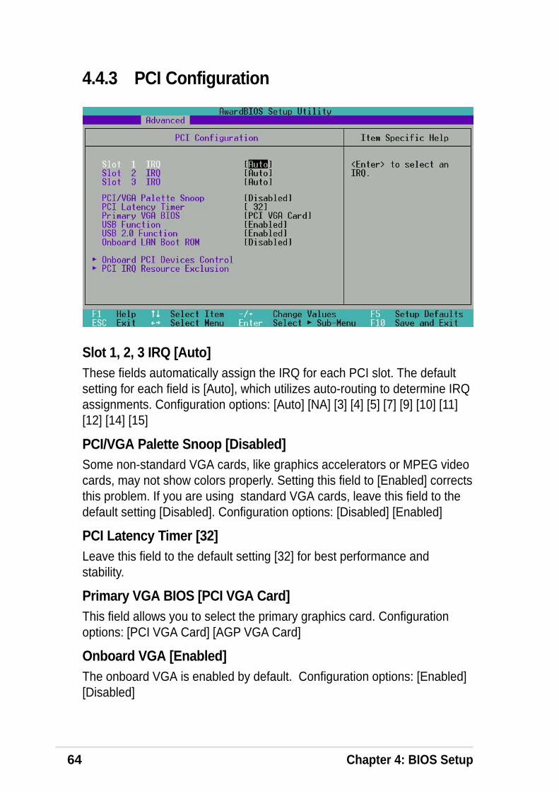
64 Chapter 4: BIOS Setup
Slot 1, 2, 3 IRQ [Auto]These fields automatically assign the IRQ for each PCI slot. The defaultsetting for each field is [Auto], which utilizes auto-routing to determine IRQassignments. Configuration options: [Auto] [NA] [3] [4] [5] [7] [9] [10] [11][12] [14] [15]
PCI/VGA Palette Snoop [Disabled]Some non-standard VGA cards, like graphics accelerators or MPEG videocards, may not show colors properly. Setting this field to [Enabled] correctsthis problem. If you are using standard VGA cards, leave this field to thedefault setting [Disabled]. Configuration options: [Disabled] [Enabled]
PCI Latency Timer [32]Leave this field to the default setting [32] for best performance andstability.
Primary VGA BIOS [PCI VGA Card]This field allows you to select the primary graphics card. Configurationoptions: [PCI VGA Card] [AGP VGA Card]
Onboard VGA [Enabled]The onboard VGA is enabled by default. Configuration options: [Enabled][Disabled]
4.4.3 PCI Configuration
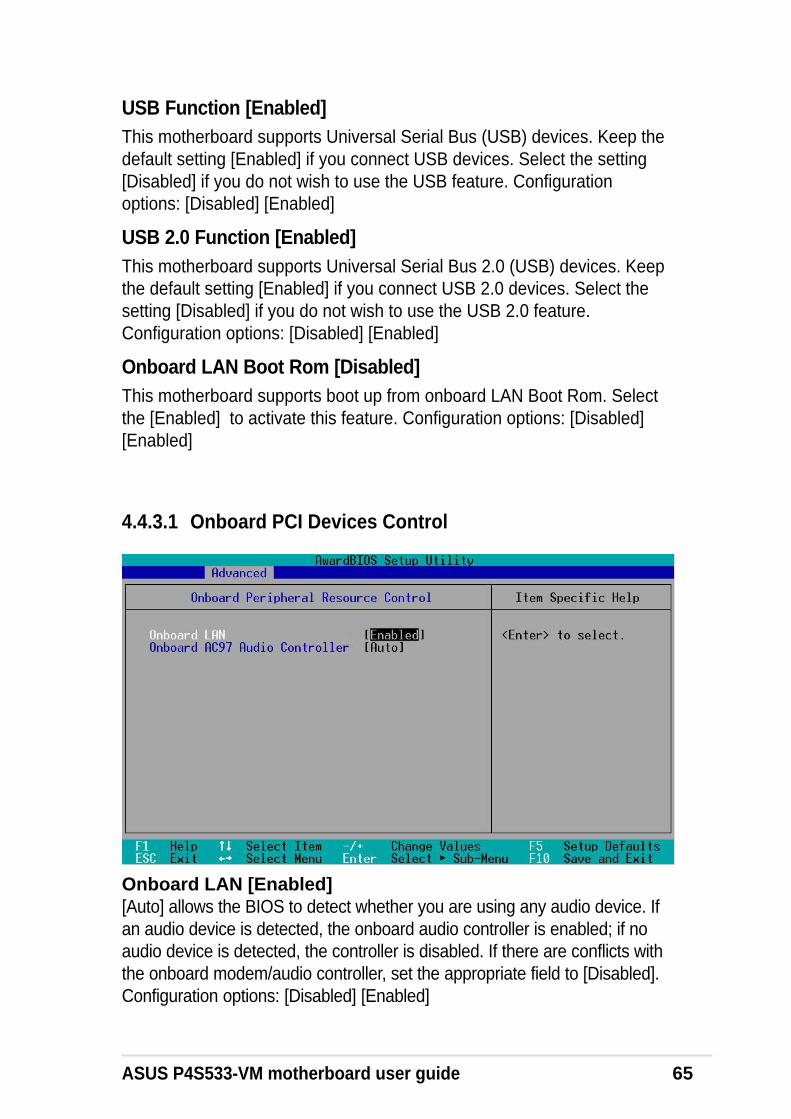
ASUS P4S533-VM motherboard user guide 65
Onboard LAN [Enabled][Auto] allows the BIOS to detect whether you are using any audio device. Ifan audio device is detected, the onboard audio controller is enabled; if noaudio device is detected, the controller is disabled. If there are conflicts withthe onboard modem/audio controller, set the appropriate field to [Disabled].Configuration options: [Disabled] [Enabled]
4.4.3.1 Onboard PCI Devices Control
USB Function [Enabled]This motherboard supports Universal Serial Bus (USB) devices. Keep thedefault setting [Enabled] if you connect USB devices. Select the setting[Disabled] if you do not wish to use the USB feature. Configurationoptions: [Disabled] [Enabled]
USB 2.0 Function [Enabled]This motherboard supports Universal Serial Bus 2.0 (USB) devices. Keepthe default setting [Enabled] if you connect USB 2.0 devices. Select thesetting [Disabled] if you do not wish to use the USB 2.0 feature.Configuration options: [Disabled] [Enabled]
Onboard LAN Boot Rom [Disabled]This motherboard supports boot up from onboard LAN Boot Rom. Selectthe [Enabled] to activate this feature. Configuration options: [Disabled][Enabled]

66 Chapter 4: BIOS Setup
IRQ XX Reserved [No/ICU]These fields indicate whether or not the displayed IRQ for each field isbeing used by a legacy (non-PnP) ISA card. The setting [No/ICU] for anIRQ field indicates that you are using the ISA Configuration Utility (ICU),and that this particular IRQ is NOT required by a legacy ISA card. Set theIRQ field to [Yes] if you install a legacy ISA card that requires a unique IRQand you are NOT using ICU. Configuration options: [No/ICU] [Yes]
4.4.3.2 PCI IRQ Resource Exclusion
Onboard AC97 Audio Controller [Auto][Auto] allows the BIOS to detect whether you are using any modem/audiodevice. If a modem/audio device is detected, the onboard modem/audiocontroller is enabled; if no modem/audio device is detected, the controller isdisabled. If there are conflicts with the onboard modem/audio controller, setthe appropriate field to [Disabled]. Configuration options: [Disabled] [Auto]
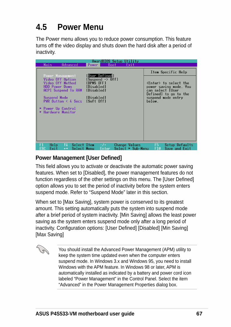
ASUS P4S533-VM motherboard user guide 67
4.5 Power MenuThe Power menu allows you to reduce power consumption. This featureturns off the video display and shuts down the hard disk after a period ofinactivity.
Power Management [User Defined]This field allows you to activate or deactivate the automatic power savingfeatures. When set to [Disabled], the power management features do notfunction regardless of the other settings on this menu. The [User Defined]option allows you to set the period of inactivity before the system enterssuspend mode. Refer to “Suspend Mode” later in this section.
When set to [Max Saving], system power is conserved to its greatestamount. This setting automatically puts the system into suspend modeafter a brief period of system inactivity. [Min Saving] allows the least powersaving as the system enters suspend mode only after a long period ofinactivity. Configuration options: [User Defined] [Disabled] [Min Saving][Max Saving]
You should install the Advanced Power Management (APM) utility tokeep the system time updated even when the computer enterssuspend mode. In Windows 3.x and Windows 95, you need to installWindows with the APM feature. In Windows 98 or later, APM isautomatically installed as indicated by a battery and power cord iconlabeled “Power Management” in the Control Panel. Select the item“Advanced” in the Power Management Properties dialog box.

68 Chapter 4: BIOS Setup
Video Off Option [Suspend -> Off ]This field determines when to activate the video off feature for monitorpower management. Configuration options: [Always On] [Suspend -> Off]
Video Off Method [DPMS OFF]This field defines the video off features. The Display Power ManagementSystem (DPMS) feature allows the BIOS to control the video display card ifit supports the DPMS feature. [Blank Screen] only blanks the screen. Usethis for monitors without power management or “green” features.
Even if installed, your screen saver does not display when you select[Blank Screen] for the above field.
[V/H SYNC+Blank] blanks the screen and turns off vertical and horizontalscanning. Configuration options: [Blank Screen] [V/H SYNC+Blank][DPMS Standby] [DPMS Suspend] [DPMS OFF] [DPMS Reduce ON]
HDD Power Down [Disabled]Shuts down any IDE hard disk drives in the system after a period ofinactivity as set in this user-configurable field. This feature does not affectSCSI hard drives. Configuration options: [Disabled] [1 Min] [2 Min] [3Min]...[15 Min]
ACPI Suspend To RAM [Disabled]This field allows you to enable or disable the ACPI Suspend-to-RAMfeature. To support this feature, the +5VSB of the power supply shouldhave the capacity to provide more than 720mA current. Configurationoptions: [Disabled] [Enabled]
Suspend Mode [Disabled]Sets the time period before the system goes into suspend mode.Configuration options: [Disabled] [1~2 Min] [2~3 Min] [4~5 min] [8~9 Min][20 Min] [30 Min]
PWR Button < 4 Secs [Soft Off]When set to [Soft off], the ATX switch can be used as a normal systempower-off button when pressed for less than 4 seconds. [Suspend] allowsthe button to have a dual function where pressing less than 4 secondsputs the system in sleep mode. Regardless of the setting, holding the ATXswitch for more than 4 seconds powers off the system. Configurationoptions: [Soft off] [Suspend]
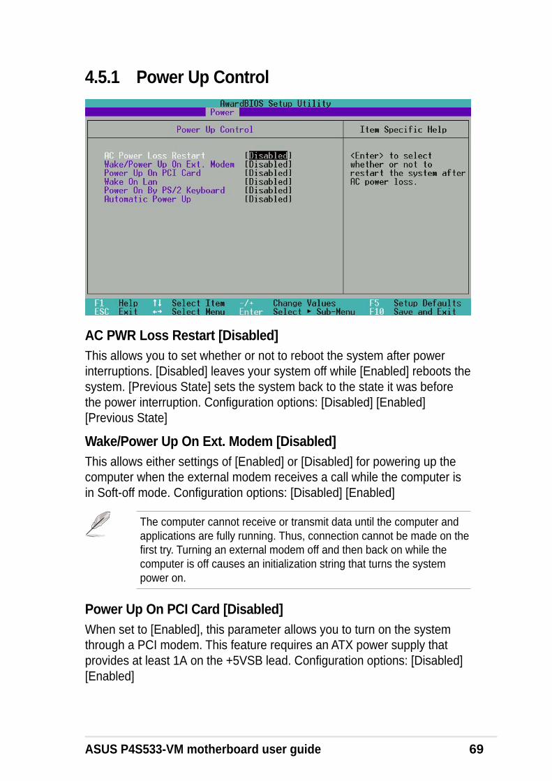
ASUS P4S533-VM motherboard user guide 69
4.5.1 Power Up Control
AC PWR Loss Restart [Disabled]This allows you to set whether or not to reboot the system after powerinterruptions. [Disabled] leaves your system off while [Enabled] reboots thesystem. [Previous State] sets the system back to the state it was beforethe power interruption. Configuration options: [Disabled] [Enabled][Previous State]
Wake/Power Up On Ext. Modem [Disabled]This allows either settings of [Enabled] or [Disabled] for powering up thecomputer when the external modem receives a call while the computer isin Soft-off mode. Configuration options: [Disabled] [Enabled]
The computer cannot receive or transmit data until the computer andapplications are fully running. Thus, connection cannot be made on thefirst try. Turning an external modem off and then back on while thecomputer is off causes an initialization string that turns the systempower on.
Power Up On PCI Card [Disabled]When set to [Enabled], this parameter allows you to turn on the systemthrough a PCI modem. This feature requires an ATX power supply thatprovides at least 1A on the +5VSB lead. Configuration options: [Disabled][Enabled]

70 Chapter 4: BIOS Setup
Wake On LAN [Disabled]When set to [Enabled], this item allows you to turn on the system throughthe onboard LAN. This feature requires an ATX power supply that providesat least 1A on the +5VSB lead. Configuration options: [Disabled] [Enabled]
Power On By PS/2 Keyboard [Disabled]This parameter allows you to use specific keys on the keyboard to turn onthe system. This feature requires an ATX power supply that provides atleast 1A on the +5VSB lead. Configuration options: [Disabled] [Space Bar][Ctrl-Esc] [Power Key]
Automatic Power Up [Disabled]This allows an unattended or automatic system power up. You mayconfigure your system to power up at a certain time of the day by selecting[Everyday] or at a certain time and day by selecting [By Date].Configuration options: [Disabled] [Everyday] [By Date]

ASUS P4S533-VM motherboard user guide 71
4.5.2 Hardware Monitor
MB Temperature [xxxC/xxxF]CPU Temperature [xxxC/xxxF]The onboard hardware monitor automatically detects the MB(motherboard) and CPU temperatures.
CPU Fan Speed [xxxxRPM] or N/AChassis Fan Speed [xxxxRPM] or N/AThe onboard hardware monitor automatically detects the CPU and chassisfan speeds and displays the fan speeds in revolutions per minute (RPM). Ifany of the fans is not connected to the fan connectors on the motherboard,the specific field will show N/A.
VCORE Voltage, +3.3V Voltage, +5V Voltage, +12V VoltageThe onboard hardware monitor automatically detects the voltage outputthrough the onboard voltage regulators and show the values on thesefields.

72 Chapter 4: BIOS Setup
Boot SequenceThe Boot menu allows you to select among the four possible types of bootdevices listed using the up and down arrow keys. By using the <+> or<Space> key, you can promote devices and by using the <-> key, you candemote devices. Promotion or demotion of devices alters the priority whichthe system uses to search for a boot device on system power up.Configuration fields include Removable Devices, IDE Hard Drive, ATAPICD-ROM, and Other Boot Device.
Removable Device [Legacy Floppy]Configuration options: [Disabled] [Legacy Floppy] [LS-120] [ZIP][ATAPIMO]
IDE Hard DriveThis field allows you to select which IDE hard disk drive to use in the bootsequence. Pressing [Enter] will show the product IDs of all connected IDEhard disk drives.
ATAPI CD-ROMThis field allows you to select which ATAPI CD-ROM drive to use in theboot sequence. Pressing [Enter] will show the product IDs of all yourconnected ATAPI CD-ROM drives.
Other Boot Device Select [INT18 Device (Network)]Configuration options: [Disabled] [SCSI Boot Device] [INT18 Device(Network)]
4.6 Boot Menu

ASUS P4S533-VM motherboard user guide 73
Plug & Play O/S [No]This field allows you to use a Plug-and-Play (PnP) operating system toconfigure the PCI bus slots instead of using the BIOS. When [Yes] isselected, interrupts may be reassigned by the OS. If you installed a non-PnP OS or if you want to prevent reassigning of interrupt settings, keepthe default setting [No]. Configuration options: [No] [Yes]
Boot Virus Detection [Enabled]This field allows you to set boot virus detection, ensuring a virus-free bootsector. The system halts and displays a warning message when it detectsa virus. If this occurs, you can either allow the operation to continue or usea virus-free bootable floppy disk to restart and investigate your system.Configuration options: [Disabled] [Enabled]
Quick Power On Self Test [Enabled]This field speeds up the Power-On-Self Test (POST) routine by skippingretesting a second, third, and fourth time. Configuration options: [Disabled][Enabled]
Boot Up Floppy Seek [Enabled]When enabled, the BIOS will seek the floppy disk drive to determinewhether the drive has 40 or 80 tracks. Configuration options: [Disabled][Enabled]
Full Screen Logo [Enabled]This field enables the display of the full screen logo that appears as thePC boots up. Configuration options: [Disabled] [Enabled]
Make sure that the above item is set to [Enabled] if you wish to use theASUS MyLogo2™ feature.
Interrupt Mode [APIC]This item controls the IRQ structure. The new APIC creates a range of IRQslarger than the standard 16 IRQ channels. The standard setting of PIC limitsthe number of IRQs to the standard IRQ0 to IRQ15. Windows 2000 and XPsupport APIC settings. Select between new APIC or PIC. Configurationoptions: [APIC] [PIC]
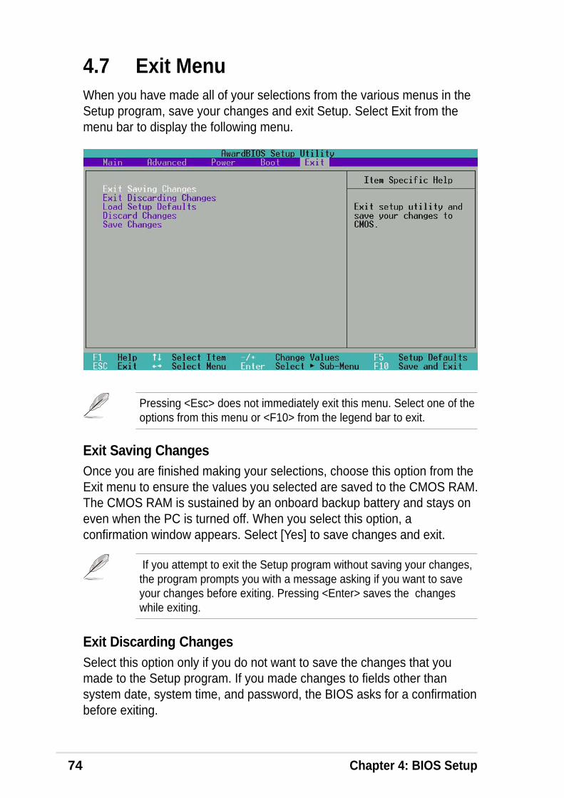
74 Chapter 4: BIOS Setup
4.7 Exit MenuWhen you have made all of your selections from the various menus in theSetup program, save your changes and exit Setup. Select Exit from themenu bar to display the following menu.
Exit Saving ChangesOnce you are finished making your selections, choose this option from theExit menu to ensure the values you selected are saved to the CMOS RAM.The CMOS RAM is sustained by an onboard backup battery and stays oneven when the PC is turned off. When you select this option, aconfirmation window appears. Select [Yes] to save changes and exit.
Pressing <Esc> does not immediately exit this menu. Select one of theoptions from this menu or <F10> from the legend bar to exit.
If you attempt to exit the Setup program without saving your changes,the program prompts you with a message asking if you want to saveyour changes before exiting. Pressing <Enter> saves the changeswhile exiting.
Exit Discarding ChangesSelect this option only if you do not want to save the changes that youmade to the Setup program. If you made changes to fields other thansystem date, system time, and password, the BIOS asks for a confirmationbefore exiting.

ASUS P4S533-VM motherboard user guide 75
Load Setup DefaultsThis option allows you to load the default values for each of theparameters on the Setup menus. When you select this option or if youpress <F5>, a confirmation window appears. Select [Yes] to load defaultvalues. Select Exit Saving Changes or make other changes before savingthe values to the non-volatile RAM.
Discard ChangesThis option allows you to discard the selections you made and restore thepreviously saved values. After selecting this option, a confirmationappears. Select [Yes] to discard any changes and load the previouslysaved values.
Save ChangesThis option saves your selections without exiting the Setup program. Youcan then return to other menus and make further changes. After you selectthis option, a confirmation window appears. Select [Yes] to save anychanges to the non-volatile RAM.

76 Chapter 4: BIOS Setup

Chapter 5
Software support

ASUS P4S533-VM motherboard
ASUS P4S533-VM motherboard user guide 77
5.1 Install an operating systemThis motherboard supports Windows 98/ME/NT/2000/XP and OS/2 operatingsystem (OS). Always install the latest OS version and corresponding updatesso you can maximize the features of your hardware.
5.1.1 Windows first time installation
When you start Windows for the first time after installing the motherboard,Windows detects all Plug-n-Play devices devices. Follow the Add NewHardware wizard to install the necessary device drivers. When prompted torestart, select No. Refer to the following sections in this chapter to install thesoftware and drivers contained in the support CD.
NOTE! Because motherboard settings and hardware options vary, usethe setup procedures presented in this chapter for general reference only.Refer to your OS documentation for more information.
5.2 Support CD informationThe support CD that came with the motherboard contains useful softwareand several utility drivers that enhance the motherboard features.
5.2.1 Running the support CD
To begin using the support CD, simply insert the CD into your CD-ROMdrive. The CD automatically displays the welcome screen and the installationmenus if Autorun is enabled in your computer.
NOTE! The contents of the support CD are subject to change at anytime without notice. Visit the ASUS website for updates.
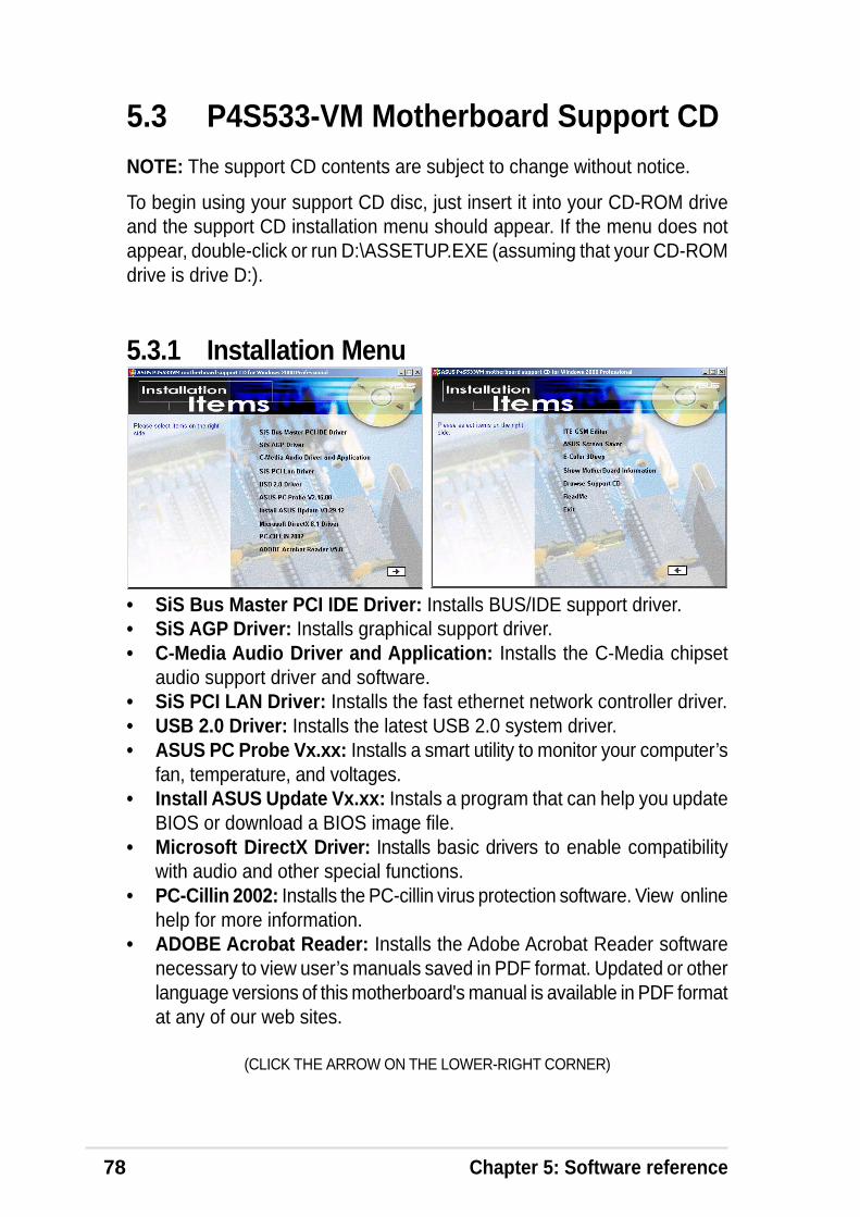
78 Chapter 5: Software reference
5.3 P4S533-VM Motherboard Support CDNOTE: The support CD contents are subject to change without notice.
To begin using your support CD disc, just insert it into your CD-ROM driveand the support CD installation menu should appear. If the menu does notappear, double-click or run D:\ASSETUP.EXE (assuming that your CD-ROMdrive is drive D:).
5.3.1 Installation Menu
• SiS Bus Master PCI IDE Driver: Installs BUS/IDE support driver.• SiS AGP Driver: Installs graphical support driver.• C-Media Audio Driver and Application: Installs the C-Media chipset
audio support driver and software.• SiS PCI LAN Driver: Installs the fast ethernet network controller driver.• USB 2.0 Driver: Installs the latest USB 2.0 system driver.• ASUS PC Probe Vx.xx: Installs a smart utility to monitor your computer’s
fan, temperature, and voltages.• Install ASUS Update Vx.xx: Instals a program that can help you update
BIOS or download a BIOS image file.• Microsoft DirectX Driver: Installs basic drivers to enable compatibility
with audio and other special functions.• PC-Cillin 2002: Installs the PC-cillin virus protection software. View online
help for more information.• ADOBE Acrobat Reader: Installs the Adobe Acrobat Reader software
necessary to view user’s manuals saved in PDF format. Updated or otherlanguage versions of this motherboard's manual is available in PDF formatat any of our web sites.
(CLICK THE ARROW ON THE LOWER-RIGHT CORNER)
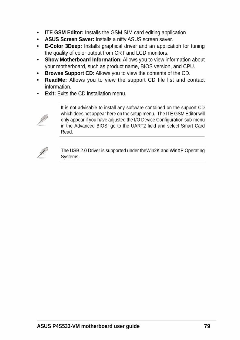
ASUS P4S533-VM motherboard user guide 79
• ITE GSM Editor: Installs the GSM SIM card editing application.• ASUS Screen Saver: Installs a nifty ASUS screen saver.• E-Color 3Deep: Installs graphical driver and an application for tuning
the quality of color output from CRT and LCD monitors.• Show Motherboard Information: Allows you to view information about
your motherboard, such as product name, BIOS version, and CPU.• Browse Support CD: Allows you to view the contents of the CD.• ReadMe: Allows you to view the support CD file list and contact
information.• Exit: Exits the CD installation menu.
It is not advisable to install any software contained on the support CDwhich does not appear here on the setup menu. The ITE GSM Editor willonly appear if you have adjusted the I/O Device Configuration sub-menuin the Advanced BIOS; go to the UART2 field and select Smart CardRead.
The USB 2.0 Driver is supported under theWin2K and WinXP OperatingSystems.

80 Chapter 5: Software reference
5.4 ASUS PC ProbeASUS PC Probe is a convenient utility to continuously monitor yourcomputer system’s vital components, such as fan rotations, Voltages, andtemperatures. It also has a utility that lets you review useful information aboutyour computer, such as hard disk space, memory usage, and CPU type,CPU speed, and internal/external frequencies through the DMIExplorer.
5.4.1 Starting ASUS PC Probe
When ASUS PC Probe starts, a splash screen appears allowing you to selectwhether or not to show the screen the next time you open PC Probe. Tobypass this startup screen, clear the Show up in next execution checkbox.
The PC Probe icon will appear on the taskbar’s system tray indicatingthat ASUS PC Probe is running. Clicking the icon will allow you to see thestatus of your PC.
To start ASUS PC Probe, click the Windows Start button, point to Programs,and then ASUS Utility, and then click Probe Vx.xx.

ASUS P4S533-VM motherboard user guide 81
5.4.2 Using ASUS PC Probe
Monitoring
Monitor SummaryShows a summary of the items beingmonitored.
Temperature MonitorShows the PC’s temperature.
Temperature Warningthreshold adjustment
(Move the slider up to increase thethreshold level or down to decrease
the threshold level)
Fan MonitorShows the PC’s fan rotation.
Voltage MonitorShows the PC’s voltages.
Fan Warningthreshold adjustment
(Move the slider up to increase thethreshold level or down to decrease
the threshold level)
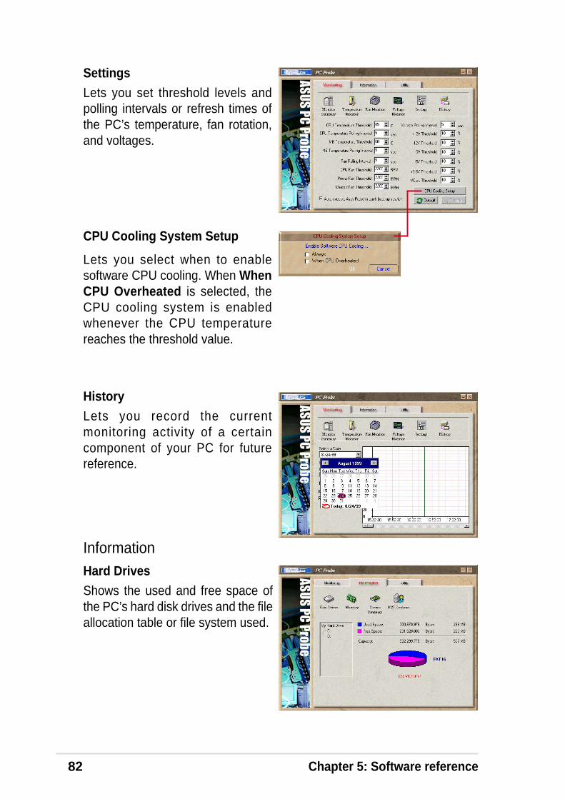
82 Chapter 5: Software reference
Information
SettingsLets you set threshold levels andpolling intervals or refresh times ofthe PC’s temperature, fan rotation,and voltages.
HistoryLets you record the currentmonitoring activity of a certaincomponent of your PC for futurereference.
Hard DrivesShows the used and free space ofthe PC’s hard disk drives and the fileallocation table or file system used.
CPU Cooling System Setup
Lets you select when to enablesoftware CPU cooling. When WhenCPU Overheated is selected, theCPU cooling system is enabledwhenever the CPU temperaturereaches the threshold value.
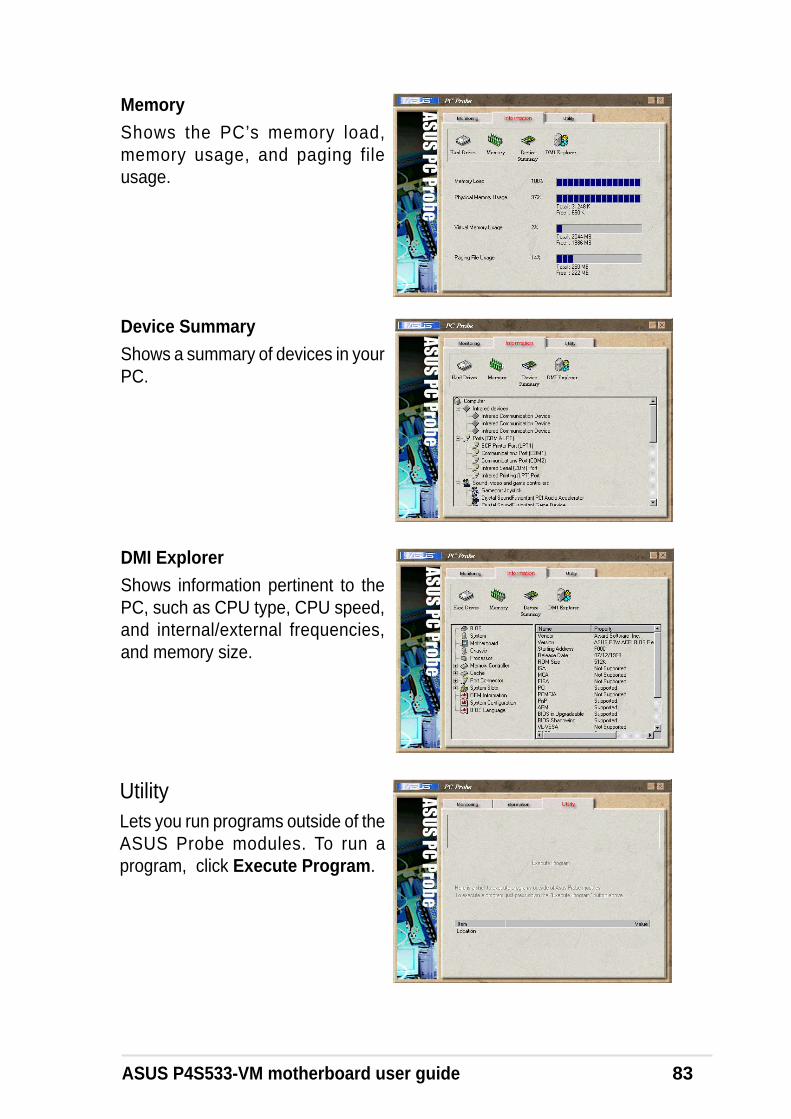
ASUS P4S533-VM motherboard user guide 83
Device SummaryShows a summary of devices in yourPC.
DMI ExplorerShows information pertinent to thePC, such as CPU type, CPU speed,and internal/external frequencies,and memory size.
UtilityLets you run programs outside of theASUS Probe modules. To run aprogram, click Execute Program.
MemoryShows the PC ’s memory load,memory usage, and paging fileusage.

84 Chapter 5: Software reference
5.4.3 ASUS PC Probe Task Bar Icon
When the ASUS PC Probesenses a problem with yourPC, portions of the ASUS PCProbe icon changes to red, thePC speaker beeps, and theASUS PC Probe monitor isdisplayed.
Right-clicking the PC Probeicon will bring up a menu toopen or exit ASUS PC Probeand pause or resume allsystem monitoring.

ASUS P4S533-VM motherboard user guide 85
5.5 ASUS Live UpdateASUS LiveUpdate is a utility that allows you to update your motherboard’sBIOS and drivers. The use of this utility requires that you are properlyconnected to the Internet through an Internet Service Provider (ISP).
1. Start ASUS Update. Launch theutility from your Windows Startmenu:Programs/AsusUpdate.
2. Select an update method.
3. If you selected “downloading fromthe Internet,” you will need to selectan Internet site. Choose the site thatis closest to you or click Auto Select.
4. From the FTP site, select the BIOSversion that you wish to download.Click Next.
5. Follow the instructions on thesucceeding screens to complete theupdate process. If you selected theoption to update the BIOS from a file,a window pops up prompting you tolocate the file. Select the file, clickSave, then follow the screeninstructions to complete the updateprocess.

86 Chapter 5: Software reference
5.6 3Deep Color TunerThe 3-Deep color tuner is designed to match your CRT or LCD colormonitor to maximize the color quality of all graphical applications. Usersmay also tune their internet applications to match “true” internet source colorswith the color displayed on the monitor.
Simply run the setup program from the start menu and follow the instructionson the various setup/test screens.
5.6.1 3Deep Color Tuning
2. Follow the instructions to manuallyadjust the brightness level of themonitor.
3. Select the faintest of the threecolors: blue, red and green.
1. Select the type of monitorconnected to the computer, eitherCRT or LCD.
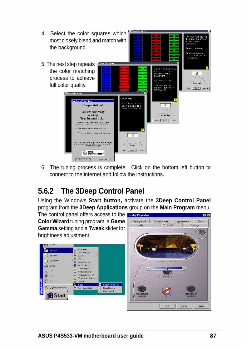
ASUS P4S533-VM motherboard user guide 87
4. Select the color squares whichmost closely blend and match withthe background.
5. The next step repeatsthe color matchingprocess to achievefull color quality.
6. The tuning process is complete. Click on the bottom left button toconnect to the internet and follow the instructions.
5.6.2 The 3Deep Control PanelUsing the Windows Start button, activate the 3Deep Control Panelprogram from the 3Deep Applications group on the Main Program menu.The control panel offers access to theColor Wizard tuning program, a GameGamma setting and a Tweak slider forbrightness adjustment.

88 Chapter 5: Software reference
5.7 ITE GSM EditorThe ITE GSM Editor is a useful application for editing and managing thedata contained on a GSM cell phone SIM card chip. This unique softwaresupports access of the SIM card “phone book.” The editor helps you to addor delete data including new names and phone numbers. The software alsoenables advanced PIN management that includes changing the PIN pluscard-lock unblocking.
Setting Up ITE GSM Editor
Connect a smart card reader to the P4S533-VM; (refer to page 38 in HardwareSetup for the connector location.) Boot-up the PC and enter BIOS (press<del>) to change the configuration to accept smart card hardware: in theAdvanced BIOS menu select the I/O Device Configuration sub-menu, go toUART2 Function Selection and choose Smart Card Read, save and exit.
Finish booting up. Insert the ASUS Support CD and click on the selection:ITE GSM Editor. The software is auto-installed to the program directory.The new program group appears:
Click on the ITE GSM Editor Icon to start-up the program.

ASUS P4S533-VM motherboard user guide 89
The ITE GSM menu:
Using the basic ITE GSM Editor:
1. Carefully remove the SIM chip from your mobile phone. The mostconvenient method to read the SIM chip is to use a conversion card: slipthe SIM chip into the conversion card and then insert it into the cardreader.
2. To access the phone book contained in the SIM card, either click the chipicon:
3. To edit data, select the fieldand double click it, or press<Enter>. Type in the nameand number:
Then click OK
Or, double click the SIM Card:
5. To save data to the SIM chip, click the save icon:
4. The data appearsin the field:
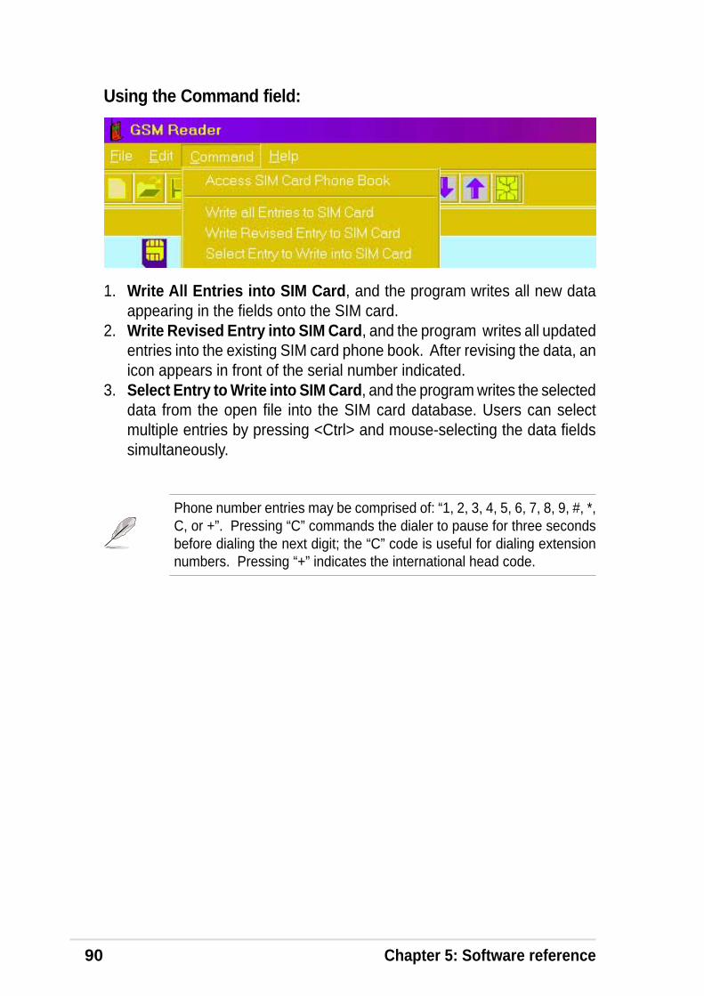
90 Chapter 5: Software reference
Using the Command field:
1. Write All Entries into SIM Card, and the program writes all new dataappearing in the fields onto the SIM card.
2. Write Revised Entry into SIM Card, and the program writes all updatedentries into the existing SIM card phone book. After revising the data, anicon appears in front of the serial number indicated.
3. Select Entry to Write into SIM Card, and the program writes the selecteddata from the open file into the SIM card database. Users can selectmultiple entries by pressing <Ctrl> and mouse-selecting the data fieldssimultaneously.
Phone number entries may be comprised of: “1, 2, 3, 4, 5, 6, 7, 8, 9, #, *,C, or +”. Pressing “C” commands the dialer to pause for three secondsbefore dialing the next digit; the “C” code is useful for dialing extensionnumbers. Pressing “+” indicates the international head code.
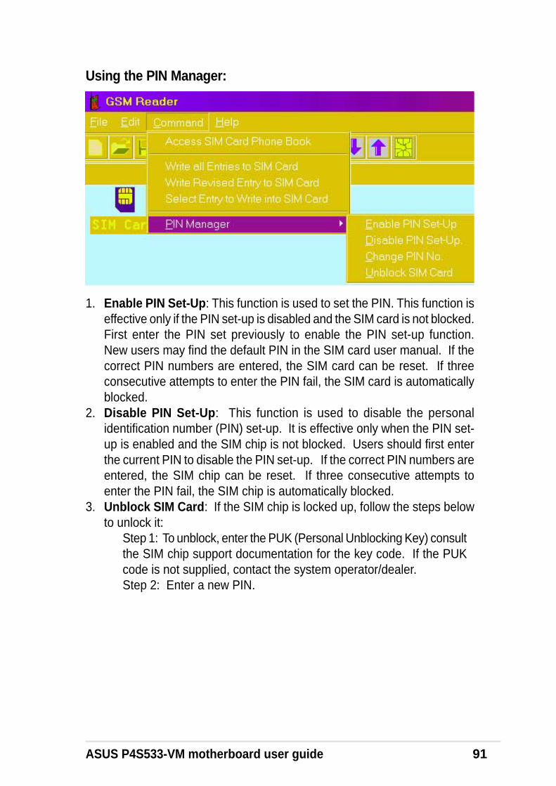
ASUS P4S533-VM motherboard user guide 91
Using the PIN Manager:
1. Enable PIN Set-Up: This function is used to set the PIN. This function iseffective only if the PIN set-up is disabled and the SIM card is not blocked.First enter the PIN set previously to enable the PIN set-up function.New users may find the default PIN in the SIM card user manual. If thecorrect PIN numbers are entered, the SIM card can be reset. If threeconsecutive attempts to enter the PIN fail, the SIM card is automaticallyblocked.
2. Disable PIN Set-Up: This function is used to disable the personalidentification number (PIN) set-up. It is effective only when the PIN set-up is enabled and the SIM chip is not blocked. Users should first enterthe current PIN to disable the PIN set-up. If the correct PIN numbers areentered, the SIM chip can be reset. If three consecutive attempts toenter the PIN fail, the SIM chip is automatically blocked.
3. Unblock SIM Card: If the SIM chip is locked up, follow the steps belowto unlock it:
Step 1: To unblock, enter the PUK (Personal Unblocking Key) consultthe SIM chip support documentation for the key code. If the PUKcode is not supplied, contact the system operator/dealer.Step 2: Enter a new PIN.


Glossary

ASUS P4S533-VM motherboard

ASUS P4S533-VM motherboard user guide 93
13941394 is the IEEE designation for a high performance serial bus tht offers data transfersat 100/200/400 Mbps. This serial bus defines both a back plane physical layer and apoint-to-point cable-connected virtual bus. The primary application of the cable versionis the integration of I/O connectivity at the back panel of personal computers using alow-cost, scalable, high-speed serial interface. The 1394 standard also provides newservices such as live connect/disconnect capability for external devices including diskdrives, printers and hand-held peripherals such as scanners and cameras. This is anew standard to complement the slower USB interface and to compete with the moreexpensive SCSI interface.AC97 (Audio Codec '97)AC '97 is the next step in enabling PCs with audio quality comparable to consumerelectronics devices. The specification defines new cost-effective options to helpintegrate the components necessary to support next-generation auto-intensive PCapplications such as DVD, 3-D multiplayer gaming and interactive music. Thespecification also defines new extensions supporting modem and docking to help bothdesktop and mobile manufacturers adopt these new technologies more quickly andcost-effectively. This specification uses software emulation to compete with the PCISoundBlaster specification.ACPI (Advanced Configuration and Power Interface)The ACPI specification defines a cross-platform interface designed to support manyoperating systems. ACPI defines a flexible and abstract hardware interface thatprovides a standard way to integrate power management features throughout a PCsystem, including hardware, operating system and application software. This enablesthe system to automatically turn ON and OFF peripherals such as CD-ROMs, networkcards, hard disk drives, and printers, as well as consumer devices connected to the PCsuch as VCRs, TVs, phones, and stereos. With this technology, peripherals will also beable to activate the PC. For example, inserting a tape into a VCR can turn on the PC,which could then activate a large-screen TV and high-fidelity sound system.AGP (Accelerated Graphics Port)An interface specification that enables high-performance 3D graphics on mainstreamPCs. AGP was designed to offer the necessary bandwidth and latency to performtexture mapping directly from system memory.
Bus Bus Frequency Bandwidth Data Transfer Rate
PCI 33MHz 33MHz 133MByte/secAGP 1X 66MHz 66MHz 266MByte/secAGP 2X 66MHz 133MHz 512MByte/secAGP 4X 66MHz 266MHz 1024MByte/sec
Backup. A copy of a file, directory, or volume on a separate storage device from theoriginal. This copy is for the purpose of data retrieval in case the original is accidentallyerased, damaged, or destroyed.BIOS (Basic Input/Output System)BIOS is a set of routines that affect how the computer transfers data between computercomponents, such as memory, disks, and the display adapter. The BIOS instructionsare built into the computer’s read-only memory. BIOS parameters can be configured bythe user through the BIOS Setup program. The BIOS can be updated using theprovided utility to copy a new BIOS file into the EEPROM.Bit (Binary Digit)A bit is he basic unit of digital data used by the computer. A bit equals either: 0 or 1.BootBoot means to start the computer operating system by loading it into system memory.When the manual instructs you to “boot” your system (or computer), it means to turn ONyour computer. “Reboot” means to restart your computer. When using Windows 95 orlater, selecting “Restart” from “Start | Shut Down...” will reboot your computer.

94 Appendix: Glossary
Bus Master IDEPIO (Programmable I/O) IDE requires that the CPU be involved in IDE access andwaiting for mechanical events. Bus master IDE transfers data to/from the memorywithout interrupting the CPU. Bus master IDE driver and bus master IDE hard diskdrives are required to support bus master IDE mode.Byte (Binary Term)One byte is a group of eight contiguous bits. A byte is used to represent a singlealphanumeric character, punctuation mark, or other symbol.Cache Memory. A type of RAM that allows a faster from the CPU than a regular RAM.The cache memory eliminates the CPU wait state. When the CPU reads data from themain memory, a copy of this data is stored in the cache memory. The next time thesame address, the data is transferred from the cache memory instead of from the mainmemory.CODEC (Compressor/Decompressor). A software component that translates video oraudio between its uncompressed form and the compressed form in which it is stored.COM PortCOM is a logical device name used by to designate the computer serial ports. Pointingdevices, modems, and infrared modules can be connected to COM ports. Each COMport is configured to use a different IRQ and address assignment.Concurrent PCIConcurrent PCI maximizes system performance with simultaneous CPU, PCI and ISAbus activities. It includes multi-transaction timing, enhanced write performance, apassive release mechanism and support for PCI 2.1 compliant delayed transactions.Concurrent PCI provides increased bandwidth, reduced system latencies, improvesvideo and audio performance, and improves processing of host based applications.CPU (Central Processing Unit)The CPU, sometimes called “Processor,” actually functions as the “brain” of thecomputer. It interprets and executes program commands and processes data stored inmemory. Currently, there are socket 370 (for Pentium III FC-PGA and Celeron-PPGA),socket 7 (for Pentium, AMD, Cyrix, IBM), slot 1 (for Pentium II and III), slot 2 (for Xeon),and slot A (for AMD) processors.Device DriverA device driver is a special set of instructions that allows the computer’s operatingsystem to communicate with devices such as VGA, audio, printer, or modem.DOS (Disk Operating System)DOS is the foundation on which all other programs and software applications operate,including Windows. DOS is responsible for allocating system resources such asmemory, CPU time, disk space, and access to peripheral devices. For this reason, DOSconstitutes the basic interface between you and your computer.DRAM (Dynamic Random Access Memory)A type of RAM that requires refresh cycles to prevent the loss of the data stored in it.There are several different types of DRAM such as, EDO DRAM (Extended Data OutputDRAM), SDRAM (Synchronous DRAM), and RDRAM (Rambus DRAM) and DDRDRAM, (Double-Data Rate DRAM).Flash ROM non-volatile memory device that retains its data even when power is removed. Thisdevice is similar to EPROM, but unlike EPROM which can be erased only using anultra-violet light, flash ROM can be electrically erased. Flash ROM is normally used forsystem BIOS, which initiates hardware devices and sets up necessary parameters forthe OS. Since the flash ROM contents can be modified, users can easily update theBIOS..IDE (Integrated Drive Electronics)IDE devices integrate the drive control circuitry directly on the drive itself, eliminating theneed for a separate adapter card (in the case for SCSI devices). UltraDMA/33 IDEdevices can achieve up to 33MB/Sec transfer.

ASUS P4S533-VM motherboard user guide 95
I/O (Input/Output)The data transfers from the input devices like a keyboard, mouse, or scanner, to theoutput devices like a printer or the monitor screen.I/O AddressThe specific memory location for a particular device. Two devices cannot share thesame I/O address space.IrDA (Infrared Data Association)An internaltional organization that creates and promotes inter-operable, low cost,infrared data interconnection standards that support a walk-up, point-to-point model.The IrDA protocol is designed to support transmission of data between two devices overshort-range point-to-point infrared at speeds between 9.6Kbps and 4Mbps.ISP (Internet Service Provider)A company that provides customer access to the Internet and the World Wide Web for afee. The ISP also provides Internet utilities and services like e-mail, newsgroup,weather reports, and a host of others. The user can connect to the ISP using a modeminstalled in the computer and connected to a phone line.LPT Port (Line Printer Port)Logical device name reserved by DOS for the computer parallel ports. Each LPT port isconfigured to use a different IRQ and address assignment.MMXA set of 57 new instructions designed to accelerate multimedia and communicationsapplications, such as 3D video, 3D sound, video conference.ModemA device that allows a computer to talk to another computer through the phone system.NetworkAn interconnected computer system linked by telephone wires, or other means.OnNowThe OnNow design initiative is a comprehensive, system-wide approach to system anddevice power control. OnNow is a term for PC that is always ON but appears OFF andresponds immediately to user or other requests. The OnNow design initiative involveschanges that will occur in the Microsoft Windows operating system, device drivers,hardware, and applications, and also relies on the changes defined in the AdvancedConfiguration and Power Interface (ACPI) specification.PC100/133This is an industry-standard designation for memory capacity as a measure of thespeed of the memory bus. New platform requirements ensure that memory does notbecome a bottleneck to system performance.PCI Bus (Peripheral Component Interconnect Local Bus)PCI bus is a standard specification that defines a 32-bit data bus interface.PCI Bus MasterThe PCI Bus Master can perform data transfer without local CPU help and the CPU canbe treated as one of the Bus Masters. PCI 2.1 supports concurrent PCI operation toallow the local CPU and bus master to work simultaneously.POST (Power On Self Test)Powering on the computer initiates the POST, a series of software-controlled diagnostictests. The POST checks system memory, the motherboard circuitry, the display, thekeyboard, the diskette drive, and other I/O devices.PS/2 PortPS/2 ports are based on IBM Micro Channel Architecture. This type of architecturetransfers data through a 16-bit or 32-bit bus. A PS/2 mouse and/or keyboard may beused on ATX motherboards.
96 Appendix: Glossary
RDRAM (Rambus DRAM)Developed by Rambus, Inc., this type of memory can deliver up to 1.6GB of data persecond. RDRAM is the first interface standard that can be directly implemented on highperformance VLSI components such as, CMOS DRAMs, memory controllers, andgraphics/video ICs.RAM (Random Access Memory). The computer’s primary storage area used to write,store, and retrieve information and program instructions which are passed to the CPUfor processing. The information in RAM can be repeatedly re-written with new data.Compared to other storage media like magnetic tape, floppy disk, and hard disk, RAMhas an extraordinarily fast access rate. RAM, however, is volatile, which means that thedata stored in it are lost when the system power is turned off, or if power glitches occur.See also DRAM and SDRAM.ROM (Read Only Memory)ROM is nonvolatile memory used to store permanent programs (called firmware) usedin certain computer components. Flash ROM (or EEPROM) can be reprogrammed withnew programs (or BIOS).SCSI (Small Computer System Interface)High speed multi-threaded I/O interface defined by the X3T9.2 committee of theAmerican National Standards Institute (ANSI) for connecting many peripheral devices.The standard started from 10MBytes/sec to 160MBytes/sec available today.SDRAM (Synchronous DRAM)A type of DRAM with access signals that are synchronized with the CPU clock,eliminating the delay associated with data transfers between the CPU and memory.SDRAM takes memory access away from the CPU control; internal registers in thememory accept the request, and lets the CPU do something else while the datarequested is assembled for the next time the CPU talks to the memory.SPD for SDRAM moduleSerial Presence Detect (SPD) is most like an ID detect for SDRAM module, it using aEEPROM component on DIMM module for storing module configuration informationinside. The Serial Presence Detect function is implemented using a 2048 bit EEPROMcomponent. This nonvolatile storage device contains data programmed by the DIMMmanufacturer that identifies the module type and various SDRAM organization andtiming parameters.System DiskA system disk contains the core file of an operating system that boots up the operatingsystem.TCP/IP (Transmission Control Protocol/Internet Protocol). The communicationsprotocol used by the UNIX system and the Internet. TCP checks for lost packets, putsthe data from multiple packets into the correct order, and requests that missing ordamaged packets be resent.USB (Universal Serial Bus)A 4-pin serial cable bus that allows up to 127 plug and play computer peripherals suchas keyboard, mouse, joystick, scanner, printer, modem, and monitor to share abandwidth through a host scheduled token based protocol. This allows attaching ordetaching while the host and other peripherals are in operation. Supports synchronousand asynchronous transfer types over the same set of wires up to 12Mbit/sec. USB 2.0provides twice the transfer rate compared to USB 1.0 and competes with the 1394standard.Wake-On-LANComputer will automatically wake-up upon receiving a wake-up packet through aNetwork interface when it is under power soft-off, suspend or sleep mode.

Index

ASUS P4S533-VM motherboard
ASUS P4S533-VM motherboard user guide 97
Index
Symbols
3Deep Color TunerUsing 86
A
Accelerated Graphics Port 23ASUS PC Probe
Using 80ASUS Update
Using 85ATAPI CD-ROM 72Automatic Power Up 71
B
BIOSAdvanced Menu 57Beep Codes 41Boot Menu 72Boot Sequence 72Exit Menu 74Language 56Legend Bar 48Main Menu 50Menu Bar 48Power Menu 67Setup Defaults, loading 75Setup Program 47Smart BIOS 2Sub-menu launching 49Updating 43
BIOS Beep Codes 41Boot Device
Selection 72Boot Up NumLock Status 55Boot Virus Detection 73
C
Central Processing Unit (CPU) 11External Frequency 25installation 12Speed 57
Chip Configuration 59Clear RTC RAM 28Connectors
chassis alarm 34digital audio 37fan 34floppy disk 34Floppy Disk Drive 9Game/MIDI 9, 31HDD LED 29infrared module 37internal audio 36Parallel Port 30power supply 35primary/secondary IDE 33PS/2 Keyboard 29PS/2 Mouse 29S/PDIF audio 37Serial Port 30Smart Card Reader 38USB 30USB header 36
CPU external freq. jumper 25
D
DDR SDRAM technology 17Digital audio interfaces
S/PDIF 3DIMM
installing 19removing 20

98 Index
E
expansion cardinstallation 21IRQ assigments 22
Expansion slots 21
F
Floppy 3 Mode 50Floppy Disk Drive Connector 9
H
Hard Disk Drives (HDDs)CHS Capacity 53Cylinders 53Heads 53LBA Capacity 53Primary/Secondary Master 51Primary/Secondary Slave 51Sectors 53Types 51
Hardware Monitor 71Heatsink
installation 14
I
Interrupt Assignments 22IRQ assignments 22ITE GSM Editor 88
J
JumperFree™ Mode 24Jumpers
Clear RTC RAM 28CPU external frequency 25JumperFree mode 24
USB device wake-up 26
K
KeyboardAuto-Repeat Delay 55Auto-Repeat Rate 55Connector 29Features 55
L
Legacy Diskette 50LiveUpdate 86
Using 86
M
MotherboardIRQ Table 22layout 8, 9placement 7screws 7
MouseConnector 29
Multi-Sector Transfers 53
O
Operating systeminstallation 77
P
Parallel Port 62Modes 62
Parallel Port Connector 30Password
Supervisor 56User 56
PC ProbeUsing 80
PCI Configuration 64PCI Latency Timer 64PCI/VGA Palette Snoop 64
DIP Switches 24

ASUS P4S533-VM motherboard user guide 99
PIO Mode 54Plug & Play O/S 73Power Management 67Power On Self Test 73PS/2 Keyboard 29PS/2 Keyboard Port 2PS/2 Mouse 29
Function Control 58PS/2 Mouse Port 2
S
SDRAMActive to Precharge Time 59CAS Latency 59Configuration 59RAS to CAS Delay 59
Serial Ports 62Connectors 30
slotsAGP 23PCI 23
Smart Card Reader 38Smart Manager 88SMART Monitoring 54Sony/Philips Digital Interface
(S/PDIF) 3Support CD 77
Welcome screen 77Suspend Mode 68System Date 50System memory
configurations 17System Time 50
U
UART2 64Ultra DMA Mode 54Universal Serial Bus (USB) 30
Ports 30USB Legacy Support 59
Using3Deep Color Tuner 86ASUS Update 85ITE GSM Editor 88LiveUpdate 86PC Probe 80
USWC 60
Z
ZIF socket 11

100 Index