P4000 Manual - Hafler Hafler P4000 is a three rack height, two channel professional power amplifier...
28
® PROFESSIONAL POWER AMPLIFIER P4000 Installation & Operation PROFESSIONAL POWER AMPL nova trans DESIGNED AND ASSEMBLED IN THE USA ®
Transcript of P4000 Manual - Hafler Hafler P4000 is a three rack height, two channel professional power amplifier...

®
PROFESSIONAL POWER AMPLIFIER
P4000Installation & Operation
PROFESSIONAL POWER AMPL
novatrans DESIGNED AND
ASSEMBLED IN THE
USA
®

NOTICE - IMPORTANT SAFETY INFORMATION
1. READ INSTRUCTIONSAll the safety and operating instructions of your Hafler equipmentshould be read before power is applied to the equipment.
2. RETAIN OWNER'S MANUALThese safety and operating instructions should be retained forfuture reference.
3. HEED WARNINGSAll warnings on the equipment and in the operating instructionsare important and should be followed.
4. FOLLOW INSTRUCTIONSAll operating and use instructions are important and should befollowed.
5. HEATThe equipment should be kept away from areas of high tempera-ture, i.e., heater vents, radiators, stoves/ovens, fireplaces, etc.
6. VENTILATIONThe equipment should be used in an area suitable for properventilation. Care should be taken not to impede airflow in andaround the cabinet.
7. WATER AND MOISTUREThe equipment should not be used in or around water, such as abathtub, sink, or swimming area. Also, the equipment should notbe used in areas prone to flooding, such as a basement.
8. POWER SOURCESThe equipment should be connected only to a power source ofthe same voltage and frequency as that listed on the rear panelabove the power cord entry point.
9. POWER CORD PROTECTIONPower cords should be arranged so they do not interfere with themovement of objects in the room: people, fan blades, utility carts,etc. Also, care should be taken that the cord is not pinched or cut,and placed so it is not in danger of being pinched or cut, as inunder a rug, around a tight corner, etc.
10. POWER CORD GROUNDINGThe power supply cord is of a three wire grounded type, designedto reduce the risk of electric shock sustained from a live cabinet.It is assumed to be of suitable length for most uses of theequipment. The use of extension cords and power strips isdiscouraged unless they are of suitable rating to deliver therequired total current for safe operation of all connected equip-ment. Furthermore, extension cords or power strips must provide
the same three wire grounded connection. It is important that theblades of the equipment’s plug be able to fully insert into themating receptacle. Never remove the round grounding pin onthe plug in an attempt to mate to a two wire ungroundedreceptacle: use a grounding adaptor with the grounding tab orwire suitably connected to earth ground.
11. NON-USE PERIODSDuring periods of extended non-use, the power cord should beunplugged from the power source.
12. CLEANINGThe equipment should be cleaned only as detailed in the operat-ing instructions.
13. OBJECT AND LIQUID ENTRYCare should be taken so that objects and/or liquids, such ascleaning fluids or beverages, are not spilled into the enclosure ofthe equipment.
14. DAMAGE REQUIRING SERVICEHafler equipment should be serviced by qualified service person-nel when:
A. The power supply cord or plug has been damaged, or
B. Objects have fallen onto, or liquid has been spilled into theequipment, or
C. The equipment has been exposed to rain, or
D. The equipment does not appear to operate normally orexhibits a marked change in performance, or
E. The equipment has been dropped, or the enclosure hasbeen damaged.
15. SERVICINGThe user should not attempt to service the equipment beyond thatwhich is described in the operating instructions. All other serviceshould be referred to qualified service personnel.
16. CARTS AND STANDSThe equipment should be used with carts or stands only ofsufficient strength and stability for the use intended.
An equipment and cart combination should be moved with care.Quick stops and starts, excessive force, and uneven surfaces maycause the equipment and cart combination to topple.
– i –
The lightning flash with arrowhead symbol within an equilateraltriangle is intended to alert the user to the presence of uninsulated"dangerous voltage" within the product's enclosure, that may be ofsufficient magnitude to constitute a risk of electric shock to persons.
The exclamation point within an equilateral triangle is intended to alertthe user of the presence of important operating and maintenance(servicing) instructions in the literature accompanying the appliance.
C A U T I O NRISK OF ELECTRIC SHOCK
DO NOT OPEN
WARNING: TO PREVENT FIRE OR SHOCK HAZARD DO NOT EXPOSE THIS EQUIPMENT TO RAIN OR MOISTURE.
!

17.00
19.00.724
5.20
10.97
channel 2
BridgedMono
Normal
P 4 0 0 0 t r a n s • n o v a
®
64
2 8
0 10
64
2 8
0 10
signa
lcli
ppin
gth
erm
alsh
ort
ther
mal
clipp
ing
signa
l
shor
t
channel 1
P E R F O R M A N C E S P E C I F I C A T I O N S
P4000
Power Rating: FTC (20Hz-20kHz, 0.2% THD)
200 wpc into 8Ω
275 wpc into 4Ω
550 wpc into 8Ω (bridged mono)
Signal-to-Noise Ratio: 100dB below rated output from 20Hz-20kHz “A” Weighted
Frequency Response: 20Hz-20kHz, ±0.1dB
Bandwidth: 0.2Hz-200kHz, +0/–3dB
Slew Rate: 100 V/µs
CMRR: >75dB at 1kHz
Input Impedance: 47,000Ω per phase balanced
Input Sensitivity Range: 710mV to 4V (@ 8Ω) per phase balanced
592mV to 4V (@ 4Ω) per phase balanced
In/Out Gain: +29dB maximum, –29dB minimum
Gain Control Range: 58dB
Damping Factor: 500 (to 1kHz); 150 (to 10kHz); 18 (to 100kHz)
Power Consumption: 120W / 1A @ 120VAC (Idle Power)
(Both Channels Driven) 250W / 2.1A @ 120 VAC (1/8 Power – 8Ω)
720W / 6A @ 120 VAC (Max. Power – 8Ω)
Controls & Switches: Front Panel Gain Control, Power Switch
Indicators: Signal LED, Clip LED, Thermal LED, Short LED, Line Power LED
Connectors: XLR & 1/4" combo input
5-way Binding Post output
IEC Standard Line input
Dimensions: 19"W x 11"D x 5-1⁄4"H (3-rack spaces)
(48.26cm x 27.94cm x 13.34cm)
Net Weight: 34 lbs. (15.42kg)
– ii –
UL®UL®C

T A B L E O F C O N T E N T S
SAFETY PRECAUTIONS ........................................................................................................................................... i
PERFORMANCE SPECIFICATIONS ......................................................................................................................... ii
INTRODUCTION ................................................................................................................................................... 1
FRONT & REAR PANEL VIEW ................................................................................................................................ 2
INSTALLATIONLocation ........................................................................................................................................................... 3AC Line ............................................................................................................................................................ 3Input ................................................................................................................................................................. 4Output Connections ......................................................................................................................................... 4Monophonic Use .............................................................................................................................................. 4
OPERATIONPower Switch ................................................................................................................................................... 6Level Controls .................................................................................................................................................. 6Input Configuration Switch ............................................................................................................................... 6Ground Switch ................................................................................................................................................. 7Short Circuit Protection .................................................................................................................................... 7LED Indicators .................................................................................................................................................. 7Warm Up ......................................................................................................................................................... 7Cleaning and Maintenance ............................................................................................................................... 7
TECHNICAL REFERENCEField Service Considerations ............................................................................................................................. 8Theory and Operation of trans•nova ................................................................................................................ 8P4000 Functional Block Diagram ..................................................................................................................... 9Schematic Diagram ........................................................................................................................................ 10PC Board Layout ............................................................................................................................................. 10Parts List ......................................................................................................................................................... 13Circuit Operation ........................................................................................................................................... 15Amplifier Module Replacement ...................................................................................................................... 18
WARRANTY ......................................................................................................................................................... 19

I N T R O D U C T I O N
– 1 –
The Hafler P4000 is a three rack height, two channel professional power amplifier suitable for use in any
situation where a moderately powered compact amplifier is required. The P4000 is particularly attractive for
use in monitoring situations. Our trans•nova circuit topology and MOSFET output stage ensures trouble-free,
long term operation and is backed by our five year warranty.
This manual contains information on using the P4000 amplifier. It is organized into three main sections.
“Installation” covers the location and connection of the amplifier in the system. Like many precision
components, careful attention to the initial setup can yield dividends in higher performance and trouble-free
use. “Operation” covers the controls and features of the amplifiers and how to use them to get the best effect.
The “Technical Reference” section contains field service information; in addition to the schematic and parts
list there are block diagrams and circuit operation explanations useful for technicians. We strongly urge
reading over the Installation and Operation portions of this manual before putting the amplifier into service.
The circuitry used in the Hafler Professional power amplifiers is our trans•nova (TRANSconductance Nodal
Voltage Amplifier, U.S. Patent 4,467,288) circuit. The P4000 also utilizes our proprietary DIAMOND
(Dynamically Invariant AMplification Optimized Nodal Drive, patent pending) transconductance driver stage
which combines the linearity of Class A operation with the current headroom of a Class B system. When
combined with the robust output stage used in the P4000, DIAMOND yields lower high frequency distortion
without the sonic degradations associated with increasing the negative feedback. We have been using
MOSFETs in our power amplifiers since the 1970's. During this time they have proven to be extremely fault
tolerant, even in abusive situations. This ruggedness enables the amplifier to drive reactive speaker loads
without the performance and sound degradations imposed by elaborate Safe Operating Area protection
schemes.
Other specialized circuits which prevent damage to the amplifier and speakers have been carefully imple-
mented. A soft start circuit prevents sending potentially destructive turn-on and turn-off transients to the
speakers. A thermal sensing network continuously monitors the heatsink temperature and shuts down the
amplifier to protect it from excessive operating heat. The need for internal fuses has been eliminated; a sensing
circuit monitors the output and shuts down operation when it detects a short at the output.
Each channel of the amplifier has been built as a self-contained module. This modular arrangement simplifies
construction and improves service accessibility. The circuit board assembly makes extensive use of surface
mount components in the low power portion of the audio circuitry. Automated equipment is used to place and
solder the components which yields greater uniformity and reliability.
The front panel has controls for input level adjustment and the power switch. In addition, LED indicators give
a visual representation of the operating status of each channel. The THERMAL and SHORT indicators light to
show when these protection circuits have been activated. The CLIP indicator helps prevent damaging the
speaker by showing when the amplifier is overdriven. The SIGNAL indicator lights to show the presence of an
audio signal.
Fro
nt
Pa
ne
l V
iew
– 2 –
Re
ar
Pa
ne
l V
iew
chan
nel 2
Bri
dged
Mon
o
Nor
mal
P4
00
0 t
r an
s•
no
va®
64
28
010
64
28
010
signa
lcli
pping
therm
al shor
t
therm
al clipp
ingsig
nal
shor
t
chan
nel 1
CH
212
0 V
~60
Hz
520W
CH
1 (
Mon
o)
A D
ivis
ion
of R
ockf
ord
Cor
p.Te
mpe
, AZ
852
81 U
.S.A
.M
ade
in t
he U
.S.A
.
Aud
io G
roun
dC
hass
.Fl
oat
CH
1
–
+
8Ω
CA
UT
I ON
RIS
K O
F E
LE
CT
RIC
SH
OC
KD
O N
OT
OP
EN
WA
RN
ING
: D
O N
OT
RE
MO
VE
CO
VE
RT
O R
ED
UC
E T
HE
RIS
K O
F F
IRE
OR
EL
EC
TR
IC S
HO
CK
DO
NO
T E
XP
OS
E T
HIS
EQ
UIP
ME
NT
TO
RA
IN O
R M
OIS
TU
RE
.
!X
LR C
onne
ctio
ns
3
21
+
–
Phon
e C
onne
ctio
ns
+–
CH
2–
+–
+
Mon
o12
5 V
T15
A
®
4–8Ω
4–8Ω
PU
SH
PU
SH
Att
enti
on: U
tilis
er u
n fu
sibl
e de
rec
hang
e de
mêm
e ty
pe.
CA
UTI
ON
: For
con
tinu
ed p
rote
ctio
n fr
om r
isk
of fi
re,
repl
ace
only
wit
h sa
me
type
and
rat
ing
of fu
se.
Cla
ss 2
Wir
ing
230
V~
50/6
0Hz
510W
T6.3
AL
250V
MO
DEL
P40
00C
E
– 3 –
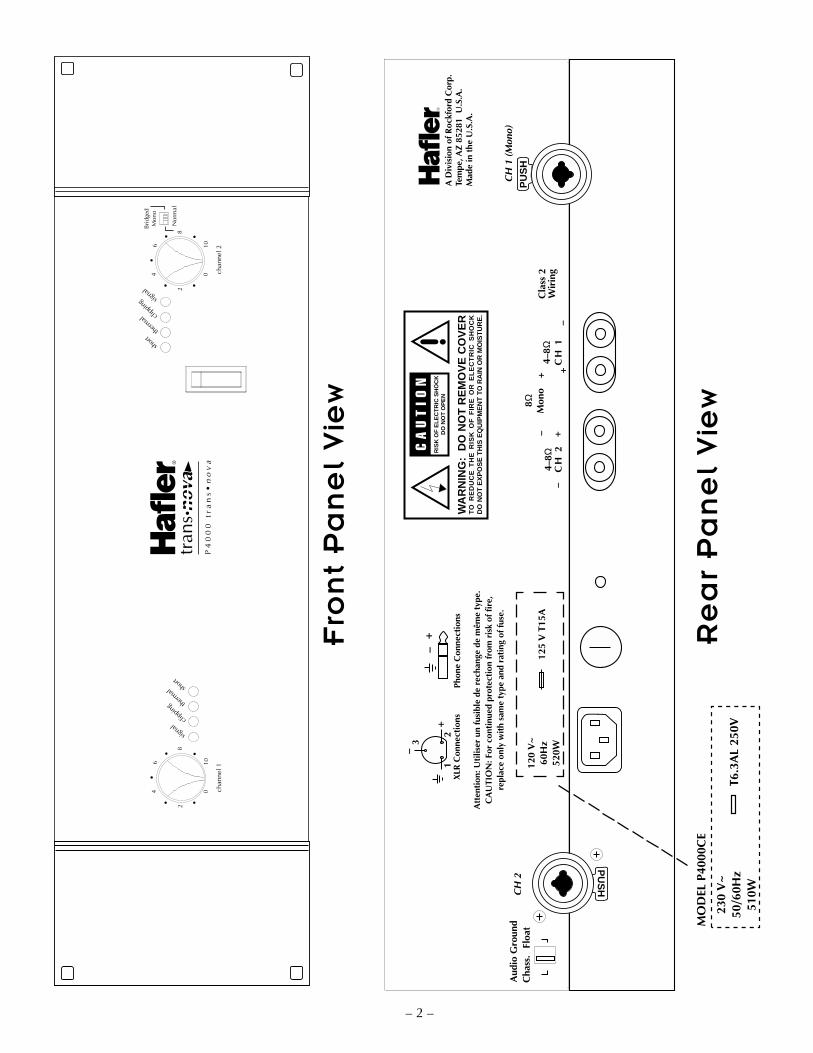
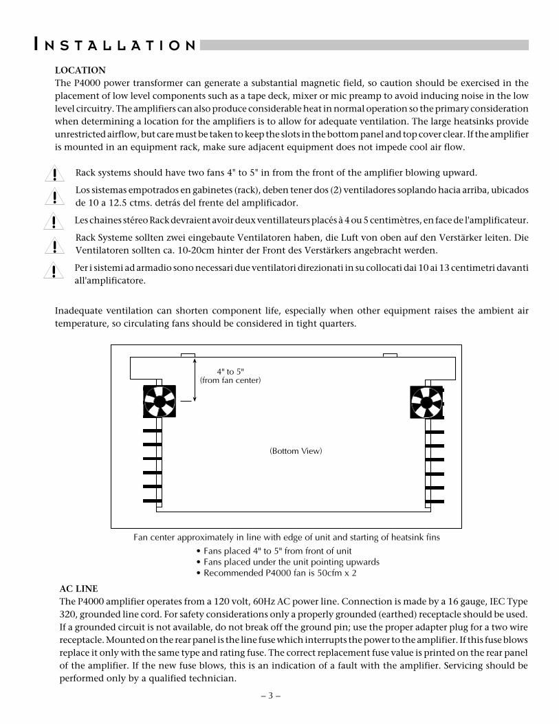
LOCATIONThe P4000 power transformer can generate a substantial magnetic field, so caution should be exercised in theplacement of low level components such as a tape deck, mixer or mic preamp to avoid inducing noise in the lowlevel circuitry. The amplifiers can also produce considerable heat in normal operation so the primary considerationwhen determining a location for the amplifiers is to allow for adequate ventilation. The large heatsinks provideunrestricted airflow, but care must be taken to keep the slots in the bottom panel and top cover clear. If the amplifieris mounted in an equipment rack, make sure adjacent equipment does not impede cool air flow.
Rack systems should have two fans 4" to 5" in from the front of the amplifier blowing upward.
Los sistemas empotrados en gabinetes (rack), deben tener dos (2) ventiladores soplando hacia arriba, ubicadosde 10 a 12.5 ctms. detrás del frente del amplificador.
Les chaines stéreo Rack devraient avoir deux ventillateurs placés à 4 ou 5 centimètres, en face de l'amplificateur.
Rack Systeme sollten zwei eingebaute Ventilatoren haben, die Luft von oben auf den Verstärker leiten. DieVentilatoren sollten ca. 10-20cm hinter der Front des Verstärkers angebracht werden.
Per i sistemi ad armadio sono necessari due ventilatori direzionati in su collocati dai 10 ai 13 centimetri davantiall'amplificatore.
Inadequate ventilation can shorten component life, especially when other equipment raises the ambient airtemperature, so circulating fans should be considered in tight quarters.
I N S T A L L A T I O N
Fan center approximately in line with edge of unit and starting of heatsink fins
• Fans placed 4" to 5" from front of unit• Fans placed under the unit pointing upwards• Recommended P4000 fan is 50cfm x 2
(Bottom View)
4" to 5"(from fan center)
AC LINEThe P4000 amplifier operates from a 120 volt, 60Hz AC power line. Connection is made by a 16 gauge, IEC Type320, grounded line cord. For safety considerations only a properly grounded (earthed) receptacle should be used.If a grounded circuit is not available, do not break off the ground pin; use the proper adapter plug for a two wirereceptacle. Mounted on the rear panel is the line fuse which interrupts the power to the amplifier. If this fuse blowsreplace it only with the same type and rating fuse. The correct replacement fuse value is printed on the rear panelof the amplifier. If the new fuse blows, this is an indication of a fault with the amplifier. Servicing should beperformed only by a qualified technician.
!!!!!
– 4 –
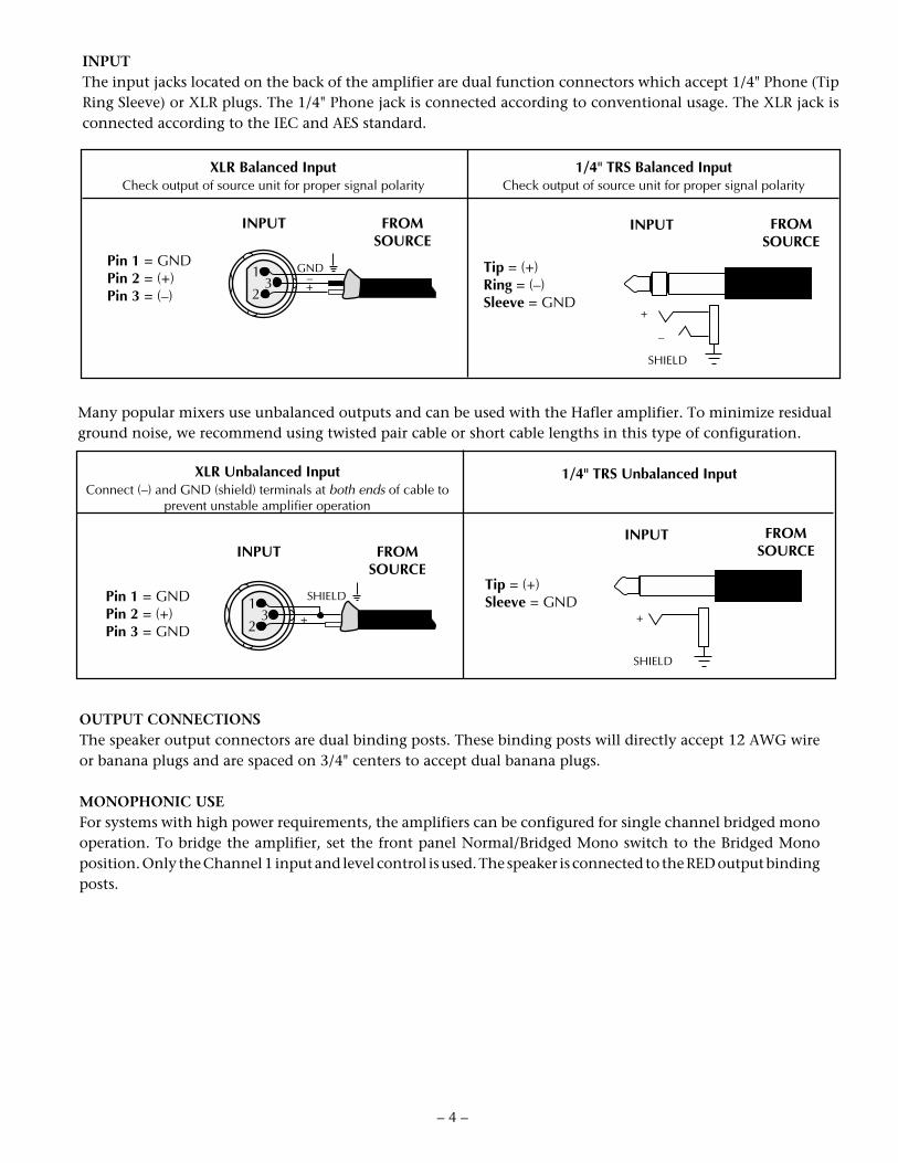
XLR Balanced InputCheck output of source unit for proper signal polarity
1/4" TRS Balanced InputCheck output of source unit for proper signal polarity
Pin 1 = GNDPin 2 = (+)Pin 3 = (–)
INPUT FROMSOURCE
Tip = (+)Ring = (–)Sleeve = GND
INPUT FROMSOURCE
Many popular mixers use unbalanced outputs and can be used with the Hafler amplifier. To minimize residualground noise, we recommend using twisted pair cable or short cable lengths in this type of configuration.
XLR Unbalanced InputConnect (–) and GND (shield) terminals at both ends of cable to
prevent unstable amplifier operation
1/4" TRS Unbalanced Input
Pin 1 = GNDPin 2 = (+)Pin 3 = GND
INPUT FROMSOURCE
Tip = (+)Sleeve = GND
INPUT FROMSOURCE
1
23
GND–+
1
23
SHIELD
+
SHIELD
SHIELD
+
–
+
INPUTThe input jacks located on the back of the amplifier are dual function connectors which accept 1/4" Phone (TipRing Sleeve) or XLR plugs. The 1/4" Phone jack is connected according to conventional usage. The XLR jack isconnected according to the IEC and AES standard.
OUTPUT CONNECTIONSThe speaker output connectors are dual binding posts. These binding posts will directly accept 12 AWG wireor banana plugs and are spaced on 3/4" centers to accept dual banana plugs.
MONOPHONIC USEFor systems with high power requirements, the amplifiers can be configured for single channel bridged monooperation. To bridge the amplifier, set the front panel Normal/Bridged Mono switch to the Bridged Monoposition. Only the Channel 1 input and level control is used. The speaker is connected to the RED output bindingposts.
!
!
– 5 –
When the amplifier is bridged the output is floating. Any speaker which requires a common ground fromthe amplifier output cannot be used in this application.
Cuando el amplificador esté en modo puente (bridge), la salida del mismo es flotante (sin neutro).Cualquier parlante que necesite una tierra común de la salida del amplificador, no puede ser usado cuandoel modo puente esté activado.
Lorsque l'amplificateur est relié, la puissance de rendement est émise. Tout haut-parleur nécessitantl'utilisation d'une même fiche que celle de l'amplificateur, ne peut pas être utilisé dans cette application.
Wenn der Verstärker gebrückt wird, ist der Ausgang schwimmend geerdet. Alle Lautsprecher, dieallgemeine Masse vom Verstärker nutzen, können in dieser Konfiguration nicht eingesetzt werden.
Nel caso di un'amplificatore ostruito, l'uscita é fluttuante non utilizzare in questa applicazione unaltoparlante che richiede la messa a terra in comune con l'uscita dell'amplificatore.
Since a bridged amplifier shares the load between the two channels, each channel will effectively drive halfof the load. Therefore, for bridged mono operation we recommend using an eight ohm load as theminimum impedance.
Ya que un amplificador en puente comparte la carga entre los dos canales, cada canal manejaráefectivamente la mitad de la carga. Por lo que, para la operación en modo puente (mono) recomendamosel uso de una carga de ocho ohmios como la mínima impedancia.
Étant donné que l'amplificateur, une fois connecté, distribue la même charge entre les deux canaux,chaque canal conduira, de façon efficace, la moitié de la charge. C'est pourquoi, pour les opérationsconduites en “mono”, nous recommandons l'utilisation d'une charge de huit ohm comme impédanceminimale.
Wird der Verstärker gebrückt, “sieht” dieser nur die halbe angelegte Last. Aus diesem Grund geben wir fürdie gebrückte mono Operation eine minimale Last von 8 Ohm vor.
Visto che un'amplificatore ostruito divide il carico tra i due canali, ogni singolo canale in effetti conducemeta del carico. Quindi, per il funzionamento monofonico ostruito dell'amplificatore si raccomandal'utilizzo di un carico di 8 ohm impedenza minima.
!
!
!
!
!
!
!
!
– 6 –
O P E R A T I O N
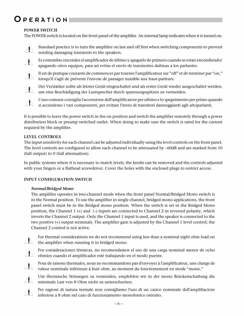
POWER SWITCHThe POWER switch is located on the front panel of the amplifier. An internal lamp indicates when it is turned on.
Standard practice is to turn the amplifier on last and off first when switching components to preventsending damaging transients to the speakers.
Es costumbre encender el amplificador de último y apagarlo de primero cuando se estan encendiendo/apagando otros equipos, para así evitar el envío de transientes dañinas a los parlantes.
Il est de pratique courante de commencer par tourner l'amplificateur sur “off” et de terminer par “on,”lorsqu'il s'agit de prévenir l'envoie de passages nuisible aux haut-parleurs.
Der Verstärker sollte als letztes Gerät eingeschaltet und als erstes Gerät wieder ausgeschaltet werden,um eine Beschädigung der Lautsprecher durch spannungsspitzen zu vermeiden.
L'uso comune consiglia l'accensione dell'amplificatore per ultimo e lo spegnimento per primo quandosi accendono i vari componenti, per evitare l'invio di transitori danneggianti agli altoparlanti.
It is possible to leave the power switch in the on position and switch the amplifier remotely through a powerdistribution block or preamp switched outlet. When doing so make sure the switch is rated for the currentrequired by the amplifier.
LEVEL CONTROLSThe input sensitivity for each channel can be adjusted individually using the level controls on the front panel.The level controls are configured to allow each channel to be attenuated by –60dB and are marked from 10(full output) to 0 (full attenuation).
In public systems where it is necessary to match levels, the knobs can be removed and the controls adjustedwith your fingers or a flathead screwdriver. Cover the holes with the enclosed plugs to restrict access.
INPUT CONFIGURATION SWITCH
Normal/Bridged MonoThe amplifier operates in two-channel mode when the front panel Normal/Bridged Mono switch isin the Normal position. To use the amplifier in single channel, bridged mono applications, the frontpanel switch must be in the Bridged mono position. When the switch is set in the Bridged Monoposition, the Channel 1 (+) and (–) inputs are connected to Channel 2 in reversed polarity, whichinverts the Channel 2 output. Only the Channel 1 input is used, and the speaker is connected to thetwo positive (+) output terminals. The amplifier gain is adjusted by the Channel 1 level control; theChannel 2 control is not active.
For thermal considerations we do not recommend using less than a nominal eight ohm load onthe amplifier when running it in bridged mono.
Por consideraciones térmicas, no recomendamos el uso de una carga nominal menor de ochoohmios cuando el amplificador esté trabajando en el modo puente.
Pour de raisons thermales, nous ne recommandons pas d'envoyer à l'amplificateur, une charge devaleur nominale inférieure à huit ohm, au moment du fonctionement en mode “mono.”
Um thermische Störungen zu vermeiden, empfehlen wir in der mono Brückenschaltung dieminimale Last von 8 Ohm nicht zu unterschreiten.
Per ragioni di natura termale non consigliamo l'uso di un carico nominale dell'amplifiactoreinferiore a 8 ohm nel caso di funzionamento monofonico ostruito.
!
!
!
!
!
!
!
!
!
!

GROUND SWITCHGround loops are characterized by a hum or buzz through the speakers and are caused by a voltage potentialdifference between two points in a ground circuit. Ground loops are aggravated when multiple paths exist fora given circuit. Mounting components in a rack with metal rails may introduce ground loops betweenassociated equipment, because the rails can establish an additional ground path.
The CHASSIS/FLOAT switch allows you to select the amplifier grounding scheme for best system compatibility.With the switch in the CHASSIS position all signal grounds are referred to the chassis and power line ground.
In the FLOAT position the signal ground is decoupled from the chassis. The position of the switch is determinedby the overall noise in the system; choose the position which gives the lowest hum.
SHORT CIRCUIT PROTECTIONDue to the self-protecting properties of the output power MOSFETs there is no need for sonically degradingvoltage and current limiting circuits. To protect the amplifier from problems which may occur in the speakerline there is an overload detection circuit.
In the event of a short in the speaker load or cables, the speaker detection circuit will shut down thatchannel and light the front panel SHORT indicator. If this happens, correct the fault and turn theamplifier off, then back on to reset.
En el caso de un corto circuito en la carga de parlantes ó en los cables, el circuito de protección apagaráel canal correspondiente e iluminará el indicador de corto (SHORT) en el panel frontal. Si esto sucede,corrija la falla y apague el amplificador, luego enciéndalo de nuevo para volver a la condición normalde operación.
En cas de court-circuit de la charge ou des câbles, le circuit de détection du haut-parleur éteindra le canalet allumera le bouton SHORT indiqué à l'avant. Si cela devait se produíre: éteignez l'amplificateur puisréallumez.
Ist ein Kurzschlub in den Lautsprechern oder in den Lautsprecherkabeln, wird eine Schutzschaltungaktiv, die den entsprechenden Kanal abschaltet. Auf der Frontseite wird dies mit einer LED angezeigt.Sollte dies einmal passieren, beheben Sie den Fehler, schalten Sie den Verstärker aus und wieder ein.Dadurch wird in dem Verstärker ein Reset durchgeführt.
Nel caso di un cortocircuito nel carico dei cavi o degli altoparlanti, il circuito rivelatore di sovratensionedell'altoparlante provvedra allo spegnimento del relativo canale e all'accensione dell'indicatoreSHORT sul pannello anteriore. In questo caso rimediare al guasto, spegnere l'amplificatore e poiripristinare.
LED INDICATORSAmplifier operation is monitored internally and each channel has four status LEDs. These indicators can beused for system troubleshooting in case of aberrant behavior.
Signal Monitors the amplifier output and lights when a signal is present. The SIGNAL indicatoris calibrated to activate an equivalent input voltage of 30mV, with the amplifier set forfull gain.
Clipping Monitors the DRIVE SIGNAL and lights when the drive signal voltage exceeds themaximum level for linear operation of the output MOSFETs.
Thermal Indicates when the thermal protection has shut down the amplifier. This occurs whenthe heatsink temperature becomes excessive.
Short Indicates when the output overload monitor detects a potentially damaging short andshuts down amplifier operation. After clearing the fault, restore normal function byturning the amplifier off, then on again.
WARM UPIn order to achieve the best sonic performance and image stability from the amplifier, we recommend lettingit warm up for 1 hour before beginning any critical listening.
CLEANING AND MAINTENANCEThere is no requirement for regular maintenance on the electronic components of the amplifier. If the casebecomes soiled it can be cleaned using a soft cloth and a mild detergent, such as spray window or glass cleaner.If the amplifier is located in a particularly dusty environment cleaning the inside with compressed air orvacuuming every 18 to 24 months is sufficient.
– 7 –
!
!
!
!
!

T E C H N I C A L R E F E R E N C E
– 8 –
FIELD SERVICE CONSIDERATIONS
A primary focus during the design and development of the P4000 was to ensure the dependability of the amplifiers. Theuse of MOSFET output transistors and the low voltage trans•nova input stage combined with careful componentselection for the circuit assembly made the reliability goals achievable. However, a parallel effort was also undertakento make sure any down time caused by an amplifier fault was minimized by making the amplifier technician “friendly.”The modular construction allows exchanging the entire operational portion of either channel quickly and easily withoutthe need for soldering or specialized equipment.
This section of the manual contains descriptions of circuit operation and block diagrams to assist technicians withcomponent level repairs.
THEORY AND OPERATION OF trans•nova
The trans•nova (TRANSconductance Nodal Voltage Amplifier) principle is based on our 1984 U.S. patent 4,467,288.This patent describes the advantages of audio power amplifiers in which a MOSFET output stage is connected in agrounded source configuration. In this connection, the output stage has its full voltage gain of typically 20dB (ten times),instead of the usual 1dB loss of voltage follower designs. The output stage is further refined into a transimpedance stage(current-to-voltage converter), to achieve extremely short loop (fast) negative feedback. The output stage is drivencooperatively by a transconductance stage (voltage-to-current converter).
Using the output stage to supply voltage gain inherently increases the power gain (for the same bandwidth) of the outputstage by typically ten times over the conventional follower connection, using the same MOSFET devices. This increasein efficiency allows the use of a much simpler input section than in the more common high voltage designs. The numberof serial stages, from input to output has been reduced from five or more to only four. This also allows the input sectionto be designed with the criteria of high quality Class A line amp with the characteristic high linearity and wide bandwidth.
The disadvantage of the Class A driver stage is the limited current headroom available. A conventional Class Atransconductance stage has a 2:1 or 6dB limit on peak to quiescent current. The number of MOSFETs used in the P4000imposes a significant capacitive load on the driver stage, enough of a load to strain the ability of the driver to deliverthe required current at the higher audio frequencies.
Since the operation of the transconductance driver stage is a major factor in the reproduction quality of the amplifier,we developed our proprietary DIAMOND (Dynamically Invariant AMplification Optimized Nodal Drive, patentapplication in process) circuit to satisfy the current headroom requirements. DIAMOND does this by smoothly andcontinuously varying the current transfer ratios of the two transconductance paths, under the control of the signal currentitself. This implementation allows the current transfer ration of one path to be smoothly and continuously reduced tozero while the other path is smoothly and continuously increased by a factor of two. This yields an additional 14dB ofcurrent headroom to drive the MOSFETs. The result is a dramatic reduction in high frequency distortion, combined withimproved ultrasonic stability.
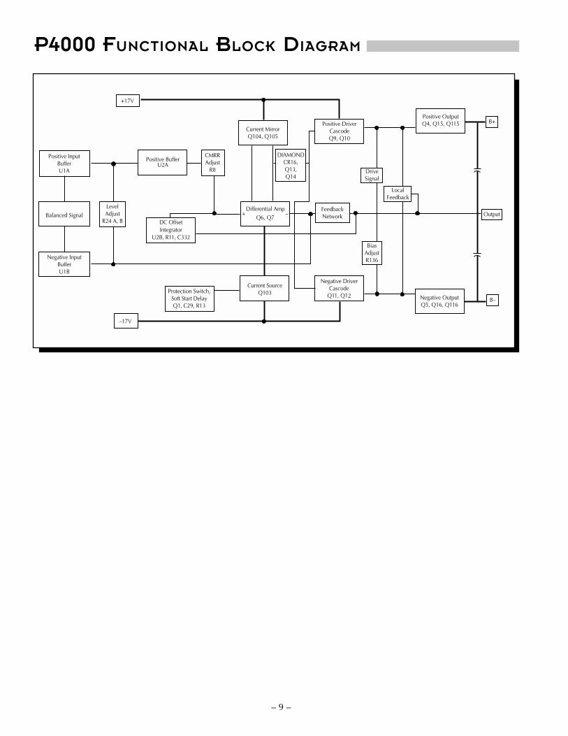
P4000 FUNCTIONAL BLOCK DIAGRAM
+17V
Positive InputBufferU1A
Balanced Signal
Negative InputBufferU1B
LevelAdjust
R24 A, B
Positive BufferU2A
CMRRAdjust
R8
Differential AmpQ6, Q7
Current MirrorQ104, Q105
Positive DriverCascodeQ9, Q10
+ –FeedbackNetwork
DriveSignal
LocalFeedback
BiasAdjustR136
Positive OutputQ4, Q15, Q115 B+
Output
B–Negative OutputQ5, Q16, Q116
Negative DriverCascode
Q11, Q12
Current SourceQ103Protection Switch,
Soft Start DelayQ1, C29, R13
–17V
DIAMONDCR16,Q13,Q14
DC OffsetIntegrator
U2B, R11, C332
– 9 –

S C H E M A T I C D I A G R A M
NOTES: Unless specified otherwise1. All resistors in ohms.2. All capacitors in microfarads.3. Channel 1 only shown.
– 10 –
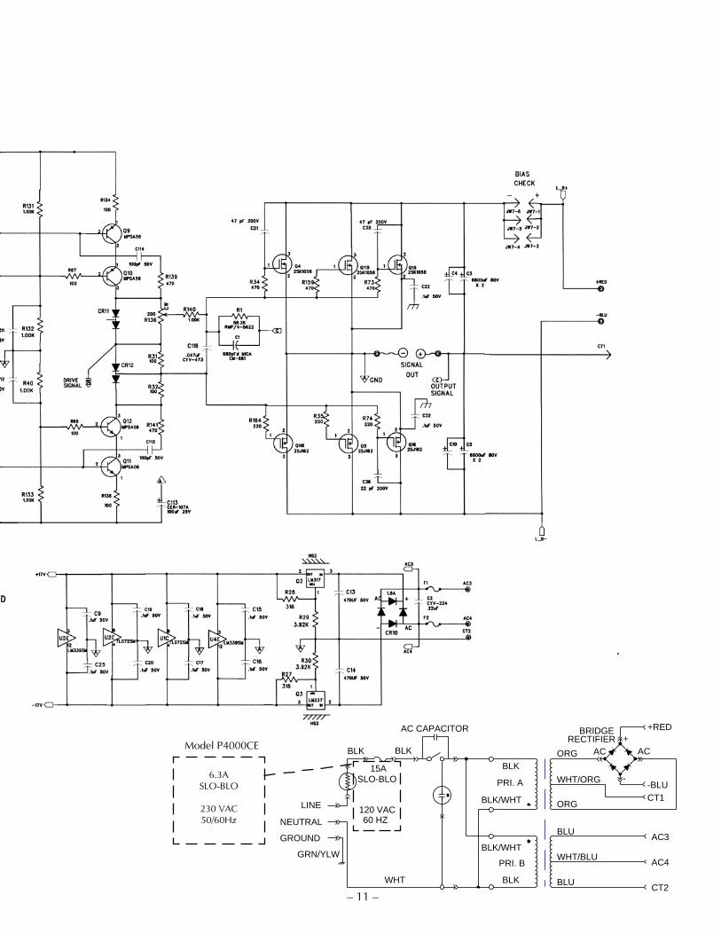
– 11 –BLK
BLK
120 VAC
PRI. B
PRI. A
BLK/WHT
BLK/WHT
60 HZNEUTRAL
LINE
BLKBLK
WHT
15ASLO-BLO
WHT/BLU
BLU
BLU
AC4
AC3
CT2
WHT/ORG
+RED
-BLUCT1
ORG
ORG AC+
AC
-
BRIDGERECTIFIER
GROUND
GRN/YLW
AC CAPACITOR
Model P4000CE
6.3ASLO-BLO
230 VAC50/60Hz

– 12 –
PC BO A R D LA Y O U T
PC-1487-C
– 13 –
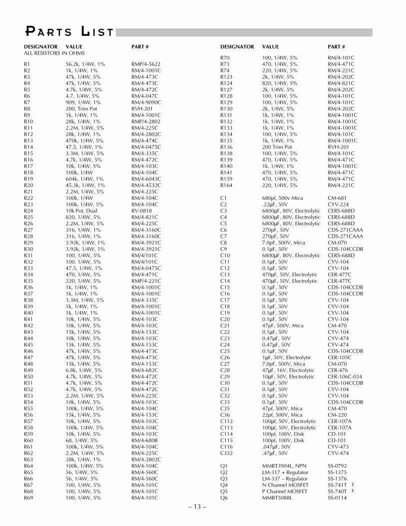
P A R T S L I S TDESIGNATOR VALUE PART #
R70 100, 1/4W, 5% RM/4-101CR73 470, 1/4W, 5% RM/4-471CR74 220, 1/4W, 5% RM/4-221CR123 2k, 1/4W, 5% RM/4-202CR124 820, 1/4W, 5% RM/4-821CR127 2k, 1/4W, 5% RM/4-202CR128 100, 1/4W, 5% RM/4-101CR129 100, 1/4W, 5% RM/4-101CR130 2k, 1/4W, 5% RM/4-202CR131 1k, 1/4W, 1% RM/4-1001CR132 1k, 1/4W, 1% RM/4-1001CR133 1k, 1/4W, 1% RM/4-1001CR134 100, 1/4W, 5% RM/4-101CR135 1k, 1/4W, 1% RM/4-1001CR136 200 Trim Pot RVH-201R138 100, 1/4W, 5% RM/4-101CR139 470, 1/4W, 5% RM/4-471CR140 1k, 1/4W, 1% RM/4-1001CR141 470, 1/4W, 5% RM/4-471CR159 470, 1/4W, 5% RM/4-471CR164 220, 1/4W, 5% RM/4-221C
C1 680pf, 500v Mica CM-681C2 .22µF, 50V CYV-224C3 6800µF, 80V, Electrolytic CERS-688DC4 6800µF, 80V, Electrolytic CERS-688DC5 6800µF, 80V, Electrolytic CERS-688DC6 270pF, 50V CDS-271CAAAC7 270pF, 50V CDS-271CAAAC8 7.0pF, 500V, Mica CM-070C9 0.1µF, 50V CDS-104CCDBC10 6800µF, 80V, Electrolytic CERS-688DC11 0.1µF, 50V CYV-104C12 0.1µF, 50V CYV-104C13 470µF, 50V, Electrolytic CER-477CC14 470µF, 50V, Electrolytic CER-477CC15 0.1µF, 50V CDS-104CCDBC16 0.1µF, 50V CDS-104CCDBC17 0.1µF, 50V CYV-104C18 0.1µF, 50V CYV-104C19 0.1µF, 50V CYV-104C20 0.1µF, 50V CYV-104C21 47pF, 500V, Mica CM-470C22 0.1µF, 50V CYV-104C23 0.47µF, 50V CYV-474C24 0.47µF, 50V CYV-474C25 0.1µF, 50V CDS-104CCDBC26 1µF, 50V, Electrolytic CER-105CC27 7.0pF, 500V, Mica CM-070C28 47µF, 16V, Electrolytic CER-476C29 10µF, 50V, Electrolytic CER-106C-024C30 0.1µF, 50V CDS-104CCDBC31 0.1µF, 50V CYV-104C32 0.1µF, 50V CYV-104C33 0.1µF, 50V CDS-104CCDBC35 47pf, 500V, Mica CM-470C36 22pf, 500V, Mica CM-220C112 100µf, 50V, Electrolytic CER-107AC113 100µf, 50V, Electrolytic CER-107AC114 100pf, 100V, Disk CD-101C115 100pf, 100V, Disk CD-101C116 .047µF, 50V CYV-473C332 .47µF, 50V CYV-474
Q1 MMBT3904L, NPN SS-0792Q2 LM-317 + Regulator SS-1375Q3 LM-337 – Regulator SS-1376Q4 N Channel MOSFET SS-741TQ5 P Channel MOSFET SS-740TQ6 MMBT5088L SS-0114
DESIGNATOR VALUE PART #ALL RESISTORS IN OHMS
R1 56.2k, 1/4W, 1% RMP/4-5622R2 1k, 1/4W, 1% RM/4-1001CR3 47k, 1/4W, 5% RM/4-473CR4 47k, 1/4W, 5% RM/4-473CR5 4.7k, 1/4W, 5% RM/4-472CR6 4.7, 1/4W, 5% RM/4-047CR7 909, 1/4W, 1% RM/4-9090CR8 200, Trim Pot RVH-201R9 1k, 1/4W, 1% RM/4-1001CR10 28k, 1/4W, 1% RMP/4-2802R11 2.2M, 1/4W, 5% RM/4-225CR12 28k, 1/4W, 1% RM/4-2802CR13 470k, 1/4W, 5% RM/4-474CR14 47.5, 1/4W, 1% RM/4-0475CR15 3.3M, 1/4W, 5% RM/4-335CR16 4.7k, 1/4W, 5% RM/4-472CR17 10k, 1/4W, 5% RM/4-103CR18 100k, 1/4W RM/4-104CR19 604k, 1/4W, 1% RM/4-6043CR20 45.3k, 1/4W, 1% RM/4-4532CR21 2.2M, 1/4W, 5% RM/4-225CR22 100k, 1/4W RM/4-104CR23 100k, 1/4W, 5% RM/4-104CR24 10k Pot, Dual RV-0818R25 820, 1/4W, 5% RM/4-821CR26 2.2M, 1/4W, 5% RM/4-225CR27 316, 1/4W, 1% RM/4-3160CR28 316, 1/4W, 1% RM/4-3160CR29 3.92k, 1/4W, 1% RM/4-3921CR30 3.92k, 1/4W, 1% RM/4-3921CR31 100, 1/4W, 5% RM/4/101CR32 100, 1/4W, 5% RM/4/101CR33 47.5, 1/4W, 1% RM/4-0475CR34 470, 1/4W, 5% RM/4-471CR35 220, 1/4W, 5% RMP/4-221CR36 1k, 1/4W, 1% RM/4-1001CR37 1k, 1/4W, 1% RM/4-1001CR38 3.3M, 1/4W, 5% RM/4-335CR39 1k, 1/4W, 1% RM/4-1001CR40 1k, 1/4W, 1% RM/4-1001CR41 10k, 1/4W, 5% RM/4-103CR42 10k, 1/4W, 5% RM/4-103CR43 15k, 1/4W, 5% RM/4-153CR44 10k, 1/4W, 5% RM/4-103CR45 15k, 1/4W, 5% RM/4-153CR46 47k, 1/4W, 5% RM/4-473CR47 47k, 1/4W, 5% RM/4-473CR48 15k, 1/4W, 5% RM/4-153CR49 6.8k, 1/4W, 5% RM/4-682CR50 4.7k, 1/4W, 5% RM/4-472CR51 4.7k, 1/4W, 5% RM/4-472CR52 4.7k, 1/4W, 5% RM/4-472CR53 2.2M, 1/4W, 5% RM/4-225CR54 10k, 1/4W, 5% RM/4-103CR55 100k, 1/4W, 5% RM/4-104CR56 15k, 1/4W, 5% RM/4-153CR57 10k, 1/4W, 5% RM/4-103CR58 100k, 1/4W, 5% RM/4-104CR59 10k, 1/4W, 5% RM/4-103CR60 68, 1/4W, 5% RM/4-680BR61 100k, 1/4W, 5% RM/4-104CR62 2.2M, 1/4W, 5% RM/4-225CR63 28k, 1/4W, 1% RM/4-2802CR64 100k, 1/4W, 5% RM/4-104CR65 56, 1/4W, 5% RM/4-560CR66 56, 1/4W, 5% RM/4-560CR67 100, 1/4W, 5% RM/4-101CR68 100, 1/4W, 5% RM/4-101CR69 100, 1/4W, 5% RM/4-101C
!!

– 14 –
DESIGNATOR VALUE PART #Q7 MMBT5088L SS-0114Q8 MMBT3904L SS-0792Q9 MPS-A56 SS-101AQ10 MPS-A56 SS-101AQ11 MPS-A06 SS-102AQ12 MPS-A06 SS-102AQ13 MMBT5088L SS-0114Q14 MMBT5087L SS-0115Q15 N Channel MOSFET SSH-741TQ16 P Channel MOSFET SSH-740TQ103 MMBTA06L SS-102SMQ104 MMBT3906L SS-0791Q105 MMBT3906L SS-0791Q115 N Channel MOSFET SSH-741TQ116 P Channel MOSFET SSH-740TCR1 LED Red SS-741CR2 LED Red SS-741CR3 LED Red SS-741CR4 LED Green SS-740CR5 MMBD914L Diode SS-803SMCR6 MMBD914L Diode SS-803SMCR7 MMBD914L Diode SS-803SMCR8 MMBD914L Diode SS-803SMCR10 Bridge Rectifier, 1.5 Amp SS-0800CR11 BAV99L Dual Diode SS-260SMCR12 BAV99L Dual Diode SS-260SMCR13 MMBD914L Diode SS-803SMCR14 BAV99L Dual Diode SS-260SMCR15 BAV99L Dual Diode SS-260SMCR16 BAV99L Dual Diode SS-260SM
J1 Input Jack, Combo CC-0588JW1 4-Pin Header CC-0970JW7 6-Pin Dual Header CC-673SW1 DPDT Slide Switch SW-0280SW2 DPDT Slide Switch SW-0280
U1 TL072CD Opamp SS-143SMU2 TL072CD Opamp SS-143SMU4 LM339 Quad Comparator SS-730SMU5 LM339 Quad Comparator SS-730SM
Power Switch SWH-1009IEC Connector CC-0852IEC Line Cord FAH-146Transformer TT-1501-BBridge Rectifier, 25 Amp SSH-609Thermistor, 10k SS-1519-AThermal Insulator HW-1494-ADual Binding Post CC-08672 by 3 Jumper CC-648Gain Knob KN-0838
F1 Fuse, 1A Fast FS-1592F2 Fuse, 1A Fast FS-1592Line Fuse Fuse, 15A Slo Blo FS-1773
Surge Limiter FA-1517-AAC Capacitor FA-1502-A
!!
!
!!
!
!
!
!
! Components marked with this symbol are safety criticaland should only be replaced with identical components.
! Los componentes marcados con el simbolo sonimprescindibles para la protección del equipo, por locual que solo sean reemplazados por los mismoscomponentes.
!
! Les componsants marqués du symbole sont indis-pensables à la sécuritée et ne peuvent être remplacésqu'avec des composants identiques.
!
! Bauteile, die mit einem gekenzeichnet sind, sindsehr wichtig und dürfen nur mit den orginal Ersatzteilenausgetauscht werden.
!
! I componenti contrassegnati da sono critici per lasicurezza e devono essere rimpiazzati solo con ricambidi valore identico.
!
!!!
!
!
Model P4000CE
IEC Line Cord FA-1464-ATransformer TT-1617-A
Fuse, 6.3A Slo Blo (5 x 20mm) FS-1835Fuse Cap FS-1125
!
!
!

CIRCUIT OPERATIONtrans•nova ImplementationThe transistor Q1 is configured to operate as a switch which controls the current source, Q103, of the input differentialamp, Q6 and Q7. When Q1 is off the emitter voltage is low turning off Q103. Timing of the Soft Start function is controlledby the charging time of C29 through R13. The THERMAL and OVERLOAD Protection circuits use Q1 to shut down thechannel when they activate.
U1A and U1B are buffer amps configured as unity gain, non-inverting voltage followers which feed the attenuatornetwork comprised of the level control R24A, and R24B and the resistor R6 which establishes the 60dB adjustmentrange. The output of U2A and U1B is connected to the input of the differential amp. U2B is configured as a DC servointegrator to null the input offset currents.
The output of the differential amp is fed to the driver stage by Q13 and Q14 which perform the DIAMONDtransconductance steering function. The cascode pairs Q9, Q10 and Q11, Q12 supply the signal voltage and currentneeded to drive the output stage Q4, Q115, Q15, and Q116, Q5, Q16.
Class AB bias current is controlled by R136.
Loop feedback is supplied by the network R1 and C1, and global feedback by R10 and C8.
CALIBRATION
WARNING: Only a competent technician should attempt the following procedure.
PRECAUCION: Sólo un técnico competente debe intentar efetuar el siguiente procedimiento.
MISE EN GARDE: Seul un technicien compétent devrait procéder à l'opération suivante.
WARNUNG: Nur ein speziell geschulter Techniker sollte die nachfolgende Prozedur durchführen.
AVVISO: La seguente procedura va eseguita soltanta da un tecnico di competenza.
Bias:The bias control establishes the quiescent Class AB output current of the amplifier. The bias should not needreadjustment from the factory setting; however, if the amplifier is repaired and output devices have been changed, orif the two channels of the amplifier do not run at the same temperature, calibrating the bias is necessary. Disconnectthe power to the amplifier before removing the cover. To adjust the bias, disconnect the input and speakers and removethe jumper JW7. Connect an amp meter across the exposed pins. Adjust R136 to get a current reading of 300 mA.
WARNING: Only a competent technician should attempt the following procedure.
PRECAUCION: Sólo un técnico competente debe intentar efetuar el siguiente procedimiento.
MISE EN GARDE: Seul un technicien compétent devrait procéder à l'opération suivante.
WARNUNG: Nur ein speziell geschulter Techniker sollte die nachfolgende Prozedur durchführen.
AVVISO: La seguente procedura va eseguita soltanta da un tecnico di competenza.
Calibrating Common Mode Rejection:The input common mode null is adjusted by the trim pot R8. The CMRR should be greater than 75dB below rated output.If the CMRR requires adjustment, feed the amplifier input with a common mode signal and adjust R8. Disconnect thepower to the amplifier before removing the cover. Use a sinewave generator set to 1 volt output at 1kHz. Connect thegenerator signal output to the tip and ring of a 1/4" plug and ground to the sleeve. Plug this into the amplifier input.Connect an AC voltmeter to the amplifier output binding posts. Adjust R8 to give the lowest voltage output from theamplifier. For a temporary adjustment when a signal generator and voltmeter are not available, use an FM tuner andtune it to an unused station as your signal source, and connect the signal to the amplifier as described above. Connectthe amplifier output to a small full range speaker. Turn the amplifier level controls full down and turn the amplifier on.Turn up the level control until you hear a signal through the speaker. Alternate between adjusting R8 for the lowest outputsignal and increasing the input control until you have the level control full. There should be very low output from theamplifier if any is detected at all.
– 15 –
– 16 –
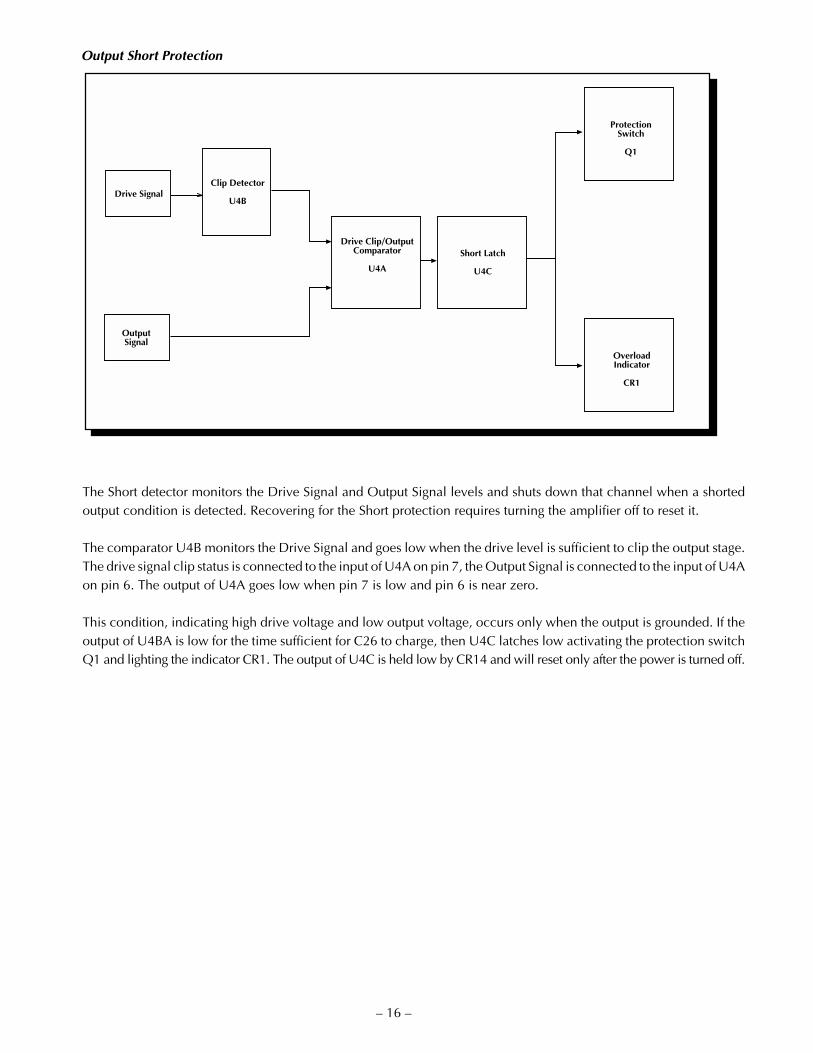
Output Short Protection
The Short detector monitors the Drive Signal and Output Signal levels and shuts down that channel when a shortedoutput condition is detected. Recovering for the Short protection requires turning the amplifier off to reset it.
The comparator U4B monitors the Drive Signal and goes low when the drive level is sufficient to clip the output stage.The drive signal clip status is connected to the input of U4A on pin 7, the Output Signal is connected to the input of U4Aon pin 6. The output of U4A goes low when pin 7 is low and pin 6 is near zero.
This condition, indicating high drive voltage and low output voltage, occurs only when the output is grounded. If theoutput of U4BA is low for the time sufficient for C26 to charge, then U4C latches low activating the protection switchQ1 and lighting the indicator CR1. The output of U4C is held low by CR14 and will reset only after the power is turned off.
Drive Signal
Drive Clip/OutputComparator
U4A
Clip Detector
U4B
OutputSignal
Short Latch
U4C
ProtectionSwitch
Q1
OverloadIndicator
CR1

TempTS1, R25
ComparatorU5B
Soft Start SwitchQ1
THERMAL IndicatorCR2
– 17 –
Thermal Protection
The thermal protection is activated, and shuts down audio operation, when the amplifier heatsink reaches anexcessively high temperature. The voltage divider R22 and R23 establishes the reference voltage on pin 5 of U5B. Thecontrol voltage on pin 4 is established by the voltage divider TS1 and R25. TS1 is a NTC (Negative TemperatureCoefficient) thermistor, mounted on the heatsink. As TS1 warms and the resistance falls, the voltage on pin 4 rises. Whenthe voltage on pin 4 exceeds the voltage on pin 5, the output on pin 2 goes low, shutting down the Soft Start switch Q1and lighting the THERMAL indicator.
Clipping Indicator
SIGNAL Indicator
CR4
LED DriverQ8
SignalDetector
U5D
AmplifierOutput
CLIP IndicatorCR3
LED DriverU5C
Clipping Detector
U5A
DriveSignal
The CLIP indicator is driven by the comparator U5A. The voltage divider R56 and R57 established the reference voltagefor the Clipping detector at pin 7 of U5A. The reference voltage scales the output of U5A to indicate when the DriveSignal, at pin 6, demands in excess of the available voltage or current of the output stage.
Signal Present Indicator
The SIGNAL indicator is controlled by the comparator U5D and the transistor Q8. The amplifier output is connectedto the input pin 9. The voltage divider R58 and R59 scales the output voltage to change the comparator output stageat an equivalent input voltage of 30mV. The output at pin 14 controls the transistor Q8 to shunt across and turn offthe LED CR4.

– 18 –
AMPLIFIER MODULE REPLACEMENTThe amplifier modules have been designed to eliminate the need for a special workplace if a field exchange becomesnecessary. All wire connections are made with quick connect terminals so soldering is not necessary. The followingtools are needed to disassemble the amplifier:
Allen wrench, 9/64Allen wrench, 7/64Phillips screwdriver, #1 tipThin nose pliers
WARNING: Only a competent technician should attempt the following procedure.
PRECAUCION: Sólo un técnico competente debe intentar efetuar el siguiente procedimiento.
MISE EN GARDE: Seul un technicien compétent devrait procéder à l'opération suivante.
WARNUNG: Nur ein speziell geschulter Techniker sollte die nachfolgende Prozedur durchführen.
AVVISO: La seguente procedura va eseguita soltanta da un tecnico di competenza.
1. Locate the 9/64 Allen head screws on the top edge of the amplifier between the heatsink fins. Remove these andthe Phillips head screws holding the input jacks on the rear panel. Lift the rear of the cover and remove it from theamplifier. Take the knobs off the level controls.
2. Remove the 9/64 Allen screw located behind the rack ears and the three 9/64 screws on the bottom edge of theheatsink. This frees the module from the chassis and it can be lifted clear.
3. Unplug the gray Mono cable connecting the two modules. Disconnect the red and black output wires and alltransformer secondary wires from the PC board and bridge rectifier.
4. Prepare a new Channel 1 module for installation by setting the NORMAL/BRIDGED MONO switch to the defaultposition according to the arrow marked on the PC board. Prepare a Channel 2 module by duplicating the switchsetting of the module which was removed.
5. Install the new module and check the position and alignment of the LEDs. Replace the level control knob and checkits alignment while securing the module.
6. After the module is secured, reconnect the wires according to the following chart:
Wire Color Function Terminal Size
Red Audio Output RED 1/4"
Black Output Ground BLK 1/4"
Orange/White Transformer Center Tap CT1 1/4"
Blue (2) Low Voltage Secondary AC3, AC4 1/8"
Blue/White Low Voltage Center Tap CT2 1/8"
+ Red High Voltage DC Bridge Rect. + 1/4"
– Blue High Voltage DC Bridge Rect. – 1/4"
SE R V I C E PO L I C Y A N D LI M I T E D WA R R A N T Y
Rockford Corporation (Hafler Division) offers a limited warranty on Hafler products on the following terms:
• Length of Warranty5 years on P1000, P1500, P3000, P40007 years on P9505 and P700090 days on all B-Stock (receipts are required)
• What is CoveredThis warranty applies only to products sold to the original owner (non-transferable). This only applies to units sold inthe Continental United States. You are required to have a copy of the receipt stating the customer's name, dealer name,product purchased and date of purchase.
• Products found to be defective during the warranty period will be repaired or replaced (with product deemed to beequivalent) at Hafler's discretion.
• What is NOT Covered1. Damage caused by accident, abuse, improper operations, water, theft2. Service performed by anyone other than Hafler or an Authorized Hafler service center3. Any product purchased outside the United States (please contact your local dealer)4. Shipping charges to get the unit to Hafler5. Any product which has had the serial number defaced, altered, or removed
• Limit on Implied WarrantiesAny implied warranties including warranties of fitness for use and merchantability are limited in duration to the periodof the express warranty set forth above. Some states do not allow limitations on the length of an implied warranty, sothis limitation may not apply. No person is authorized to assume for Rockford Fosgate any other liability in connectionwith the sale of the product.
• How to obtain service or technical supportPlease call 1-800-669-9899 for Rockford/Hafler support. You must obtain an RA # (return authorization number) toreturn any products to Hafler. You are responsible for shipment of product to Hafler.
Rockford CorporationHafler Division2055 E. 5th StreetTempe, Arizona 85281
– 19 –

– 20 –
ADVERTENCIA – INFORMACION DE SEGURIDAD IMPORTANTE
1. LEA LAS INSTRUCCIONESTodas las instrucciones de seguidad y operación de su equipoHafler, deben ser leídas antes de que el equipo sea conectadodléctricamente.
2. CONSERVE EL MANUAL DEL PROPIETARIOEstas instrucciones de seguridad y operación, deben serconservadas para futuras referencias.
3. CUADROS DE ADVERTENCIASTodas las advertencias en el equipo y en las instrucciones deoperación, son importantes y deben ser seguidas.
4. SIGA LAS INSTRUCCIONESTodas las instrucciones de uso y operación son importantes ydeben ser seguidas.
5. CALOREl equipo debe ser mantenido lejos de areas de alta temperatura,como por ejemplo: ventilaciones de calentadores, radiadores,estufas/hornos, hogueras, etc.
6. VENTILACIONEl equip debe ser usado en áreas con ventilación adecuada.Deben er tornadas las precauciones necesarias para no impedirel flujo de aire dentro y alrededor del aparato.
7. AGUA Y HUMEDADEl equipo no debe ser usado en el agua ó alrededor de ésta, talescomo en una bañera, tanque o áreas de nado. También, el equpono debe ser usado en áreas propensas a inundaciones, tales comoen un sótano.
8. FUENTES DE PODEREl equipo debe ser conectado a una fuente de poder del mismovoltaje y frecuencia que el indicado en el panel trasero sobre elpunto de entrada del cable de corriente.
9. PROTECCION DEL CABLE DE CORRIENTELos cables de corriente deben ser dispuestos de forma tal que nointerfieran con el movimiento de objetos en la sala: personas,aspas de ventilación, carretillas, etc. También, es necesario tenercuidado de que el cable no esté punzado o cortado, y debe estarubicado de forma tal que esto no ocurra, como podría sucederdebajo de una alfombra o al pasar el cable por una esquinaaguda, etc.
10. ATERRAMIENTO DEL CABLE DE CORRIENTEEl cable de corriente es del tipo aterrado de tres hilos, diseñadopara reducir el riesgo de una descarga eléctrica procendent de unchasis energizado. Se asume que su longitud es suficiente para lamayoría de usos del equipo. El uso de extensiones y multienchufes
no es recomendado, a menos que tengan el amperaje adecuadopara poder suministrar la corrioente requerida pra la operaciónsegura de todo el equipo conectado. Aun más, las extensionesdeben proveer de la misma conección aterrada de tres hiles. Esimportante que el enchufe se pueda introducir comjpletamenteen el receptáculo. Nunca remeva el pin de aterramiento en unintento por conectar el cable en un receptáculo de dos hilos noaterrado: use un adaptador de aterramiento que estéadecuadamente conectado a un punto de tierra.
11. PERIODOS SIN USODurante períodos prolongados sin uso del equipo, el cable decorriente debe ser desconectado de la fuente de electrixidad.
12. LIMPIEZAEl equip debe ser limpiado solo en la forma que se detalla en lasinstruxxiones de operación.
13. INTRODUCCIÓN DE OBJETOS Y LIQUIDODeben ser tornadas precauciones con el fin de que objetos y/ólíquidos, tales como fluidos de limpieza y gaseosas, no seanderramados dentro del chassis del aparato.
14. DAÑOS QUE REQUIEREN DE SERVICIOLos equipos Hafler deben ser llevados a servicio por personalcalificado cuando:
A. El cable de corriente ó el enchufe haya sido dañado, ó
B. Objetos ó líquido hayan sido introducidos ó derramado enel equipo, ó
C. El equipo haya sido expuesto a lluvia, ó
D. El equipo aparenta no operar normalmente ó exhibe unmarcado cambio en su desempeño, ó
E. El equipo se ha caído, o el chassis ha sido golpeado.
15. SERVICIOEl usuario no deberá intentar darle servicio al equipo más allá delo que está descrito en el instructivo de operación. Todo lodemás, deberá ser referido a servicio por personal calificado.
16. CARRETILLAS Y SOPORTESEl equipo podrá ser usado con carretillas y soportes que tenganla fortaleza y estabilidad suficiente para el uso previsto.
La combinación equipo/carretilla deberá ser movida con cuidado.Rápidas paradas y arranques, excesiva fuerza y superficiesimparejas, pueden causar el volcamiento del conjunto de carretilla/equipo.
El símbolo de flecha relámpago dentro de un triángulo equilátero, espara alertar al usario de la presencia de “voltajes peligrosos” no aisladosen el interior del aparato, los cuales pueden ser de suficiente magnitudpara constituir un riesgo de choque eléctrico a las personas.
El símbolo de exclamación dentro de un triángulo equilátero, es paraalertar al usuario de la presencia de instrucciones importantes deoperación y mantenimiento (servicio) en la documentación queacompaña al equipo.
ESPA
ÑO
L
P E L I G R ORIESGO DE DESCARGAELÉCTRICA NO ABRÍR. !
PRECAUCÍON:Para Prevenir el incendio o la descarga electrica, no
exponer este equipo a la lluvia o a la humedad.

– 21 –
ATTENTION: INFORMATIONS IMPORTANTES DE SÉCURITÉ
1. LIRE LES INSTRUCTIONSLe mode d'emploi et les mesures de sécurité de votre équipementHafler devraient être consultés avant sa mise en marche.
2. CONSERVER LE GUIDE DE L'UTILISATEURLe mode e'emploi et les mesures de sécurité devraient êtreconservés pour des références futures.
3. CONSIDÉRATIONS DE MISE EN GARDELe mode d'emploi et les mises en garde concernant cet équipementsont de grande importance et devraient être suivis.
4. SUIVRE LE MODE E'EMPLOILe mode d'emploi et les conseils d'utilisation sont importants etdevraient être suivis.
5. CHALEURLe matériel devrait être préservé loin de toute source de chaleur:radiateurs, cuisinière/fours, cheminées,…etc.
6. VENTILATIONLe matériel devrait être utilisé dans un endroit à bonne ventila-tion. Il reste nécessaire de respecter la circulation de flux d'air àl'intérier et autour du meuble.
7. EAU ET HUMIDITÉLe matériel ne devrait pas être utilisé près d'une source d'eau,telle qu'une baignoire, un évier, ou une aire de baignade. Deplus, le matériel ne devrait pas être utilisé dans des lieux sujetsaux innondations, tels que les sous-sols.
8. SOURCES D'ÉNERGIELe matériel devrait seulement être relié à une source d'énergie demême voltage et fréquence que celle indiquée sur le tableauarrière, au dessus de la fiche d'entrée de la prise de courant.
9. PROTECTION DE LA PRISE DE COURANTLa prise de courant devrait être arrangée de façon à ne pasinterférer avec le déplacement d'objets (chariots, pales deventillateurs…etc.) ou de personnes à l'intérieur de la pièce.D'autre part, il faudrait faire tres attention à ce que la prise ne soitpas percée ou coupée, ou disposée de façon à risquer de l'être,comme sous un tapis, autour d'un angle pointu…etc.
10. PRISE DE COURANT ÀTROIS FICHESLa prise de courant est composée de trois fiches, désignées àréduire le risque de décharge électrique de l'appareil.
Elle devrait être de longueur suffisante pour la plupart desutilisations de ce matériel. L'utilisation de rallonge t d'adaptateurest déconsellée à moins dêtre en mesure de fournir la chargeélectrique requise à un fonctionement sans risque, de toutmatériel relié.
11. PÉRIODES DE NON-UTILISATONDurant les périodes de non-utilisation, la prise de courant nedevrait pas être branchée à une source d'energie.
12. NETTOYAGELe matériel devrait être nettoyé en respectant les instructionsindiquées.
13. PENETRATION DES LIQUIDESUn attention particulière est éxigée quant à la dispersion deliquides tels que les produits de nettoyage et boissons, de façconà éviter toute pénetration dans l'enceinte du matériel.
14. DÉGÂT NÉCESSITANT UNE RÉVISIONLe matériel Hafler devrait être révisé par des personnes qualiféesde service après-vente, lorsque:
A. Les fiches ou la prise de courant ont été endommagé, ou:
B. De objets sont tombés sur le matériel, ou des liquides s'y sontdispersés, ou:
C. Le matériel a été exposé à la pluie, ou:
D. Le matériel ne semble pas fonctioner correctement, ouaffiche un changement de performance, ou:
E. Le matériel a été renversé à terre, ou l'enceinte a étéendommagée.
15. REVISIONL'utilisateur ne devrait pas essayer de réviser le matériel en allantplus loin que ce qui a été décrit dans le mode d'emploi. Touteautre réviion devrait être confiée à un personnel qualifié.
16. CHARRIOTS ET MEUBLESLe matériel devriat être utilisé avec des charriots et meubles dequalité et stabilité suffisante à son utilisation préconçue.
L'ensemble du matériel et du charriot devrait être déplacé avecprécaution. Des mises en marche et arrêts brusques, des colli-sions excessives ainsi que des surfaces inégales peuvent renverserl'ensemble du matériel et du charriot.
La lumière clignotante du symbole de la flêche à l'intérieur d'un triangleéquilatéral, à pour objet d'alerter l'utilisateur de la présence “d'unvoltage dangereux” non-isolé à l'intérieur du produit, qui pourrait êtrede magnitude suffisante au risque d'éléctrocution.
Le point d'exclamation, à l'intériur d'un triangle équilatéral, à pourobjet de prévenir l'utilisateur de l'importance des instructions defonctionement et de maintenance, jointes à l'appareil.
!AVERTISSEMENT:
Afin de prévenir les risques de feu ou de choc, ne pasexposer cet appareil à la pluie ou à l'humidité.
RISQUE DE CHOCÉLECTRIQUE NE PAS OUVRIR
A T T E N T I O NFR
AN
ÇA
IS

ACHTUNG – WICHTIGE SICHERHEITS – INFORMATIONEN
1. INSTSRUKTIONEN LESENAlle Sicherheits- und Operationshinweise Ihres Hafler Equip-ments sollten vor der Inbetriebnahme gelesen werden.
2. BETRIEBSANLEITUNG AUFBEWAHRENBewahren Sie die Bedienungsanleitung sorgfältig auf, damit Siein dieser auch in Zukunft nachschlagen können.
3. WARNUNGEN BEACHTENAlle Warnungen des Gerätes und der Bedienungsanleitung sindextrem wichtig und müssen befolgt werden.
4. INSTRUKTIONEN BEACHTENAlle Operations- und Gebrauchshinweise sind extrem wichtigand müssen beachtet werden.
5. HITZEDas Equipment sollte fern von Hitze ausstrahlenden Gerätenaufgestellt werden, wie z.B. Heizungen, Öfen etc.
6. VENTILATIONDas Equipment sollte so aufgestellt werden, daβ eine ausreichendeVentialition gewährt wird.
7. WASSER UND FEUCHTIGKEITDas Equipment sollte nicht im oder in der Nähe von Wasserbenutzt werden, wie z.B. in Schwimmbädem, Saunen etc. Essollte ebenfalls nicht in Überschwämmungsgefährdeten Gebietenaufgestellt werden, wie z.B. Kellerräumen.
8. STROMANSCHLUβDas Equipment darf nur an eine Stromversorgung angeschlossenwerden, die die gleichen Parameter aufweist, welche auf derRückseite, über em Anschluβterminal des Gerätes, aufgelistetsind.
9. SCHUTZ DER ZULEITUNGDie Zuletungen sollten so verlegt werden, daβ diese nicht in denBewegungsbereich anderer Möbelstücke oder Personenhereinragen. Achten Sie darauf, das das Kabel nicht gequestschtoder durchschnittren wird, wie z.B. unter Schränken oder anscharfen Kanten etc.
10. MASSEANSCHLUβDas dreiadrige Anschlubkabel ist mit einem Erdungsleiterausgestattet, welcher die Risiken eines Elektroschocks verringert.Das Kabel hat eine Länge, welche für die meisten Anwendungenvöllig ausreicht. Wenn Sie Verlängerungskabel benutzen, achtenSie darauf, das dies die erforderlichen Ströme bertragen können.Benutzen Sie immer dreiadrige Verlängerungskable.
11. ZEITRÄUME IN DENE DAS GER¨AT NICHT GENUTZT WIRDWird das Gerät über einen längeren Zeitraum nicht genutzt (z.B.Urlaub), ziehen Sie bitten den Netzstecker aus der Steckdose.
12. REINIGENReinigen Sie das Gerät nur, wie in der Bedienungsanleitungdetailliert beschrieben.
13. EINDRINGEN VON FREMDKÖRPERNAchten Sie darauf, daβ weder Fremdkörper, noch Flüssigkeiten indas Gerät eindringen.
14. ERFORDERLICHER REPARATURSERVICEHafler Equipment sollte nur von qualifizierten Service-Technikerninstand gesetzt werden, wenn:
A. Das Stromversorgungskabel beschädigt wurde
B. Eine Flüssigkeit in das Gerät eingedrimgem ist
C. Das Gerät Regen ausgesetzt wurde
D. Das Gerät nicht mehr ordnungsgemäβ funktioniert, ggf. nichtmehr die volle Leistung abgibt
E. Das Gerät runtergefallen ist oder das Gehäuse beschädigtwurde
15. SERVICEDer Benutzer sollte nur den Service ausführen, der in derBedienungsanleitung für den Benutzer freigegeben wird. Denweiterführenden Service sollte nur von qualifizierten Tevhnikerndurchgeführt werden.
16. AUFSTELLUNGDas Equipment sollte so aufgestellt werden, daβ der gewählteUntergrund die erforderliche Stabilität aufweist, so daβ einegefahrlose Bnutzong gewährleistet wird.
Das Equipment und der Untergrund sollte mit äuberster Vorsichtbewegt werden. Bei schnellen Bewegungen oder starkemAbbremsen, kann es zum Umkippen des Equipments kommen.
Der Blitz mit dem Pfeil, in einem gleihschenkligen Dreieck, soll denbenutzer vor unisolierter “gefährlicher Spannung” innerhalb des Geräteswarnen.
Das Ausrufezeichen, in einem gleichschenkligen Dreieck, soll denBenutzer darauf aufmerksam machen, daβ dem Gerät wichtigeOperaions - und Service - Informationen beigefügt sind.
– 22 –
!WARNUNG:
Um die gefahr eines elektroschocks oder feuer zuvermeiden, setzen sie das gerät keinem regen oder
extremer feuchtigkeitaus.
A C H T U N GGEFAHR EINES
ELEKTRISCHEN SCHLAGSNICHT ÖFFNEN
DEU
TSC
H
– 23 –
NOTARE – IMPORTANTI INFORMAZIONI SULLA SICUREZZA
1. LEGGETE LE ISTRUZIONITutte le istruzioni riguardanti la sicurezza ed il funzionamentodevono essere lette prima di applicare tensione all'apparato.
2. CONSERVATE IL MANUALEQueste istruzioni riguardanti la sicurezza ed il funzionamentodevono essere conservate come riferimento futuro.
3. AVVERTENZETutte le avvertenze poste sull'apparato e sul libretto di istruzionisono importanti e devono essere seguite.
4. SEGUIRE LE ISTRUZIONITuttle le istruzioni operative e di funzionamento devono essereseguite.
5. TEMPERATURAL'apparato deve essere mantenuto lontano da tuttle le zone adalta temperature, termosifoni, termoconvettori, stufe e forni,caminetti ed altro.
6. VENTILAZIONEL'apparato deve essere posizionato in aree convenienti per unacorretta ventilazione. Prestare attenzione che sia consentitacircolazione d'aria attorno e dentro il cabinet.
7. ACQUA E POLVEREL'apparato deve essere posizionato lontano da zone contenentiacqua, come vasche a bagno, acquari e piscine. Inoltre non deveessere impiegato in aree soggette ad allagamento, come lecantine.
8. REQUISITI DI ALIMENTAZIONEL'apparato deve essere connesso solo ad un'alimentazione dellastessa tensione e frequenza di quanto scritto sulla parte posterioredel telaio.
9. PROTEZIONE DEL CAVO DI ALIMENTAZIONEIl cavo di alimentazione deve essere posizionato in modo di noninterferire con il movimento di oggetti nella stanza: persone,ventilatori, carrelli, ecc…prestate attenzione anche che il cavonon sia tagliato o spellato e che non possa tagliarsi e spellarsi.
10. MESSA A TERRAIl cavo di alimentazione è del tipo a tre fili con terra ed èprogettato pr ridurre il rischio di shock elettrici. Si presume chesia della lunghezza sufficiente per la maggior parte degli impieghi.L'impiego di prolunghe e adattatori è sconsigliato se questi nongarantiscono la potenza sufficiente per i corretto fuinzionamentodegli apparati connessi. E altersì importante che vengano sempreimpiegate prolunghe con la configurazaione a tre fili con terra.
11. PERIODI DI NON UTILIZZODurante lunghi periodi di non utilizzo, staccare il cavo dialimentazione.
12. PULIZIAL'apparato deve essere pulito solo come indicato dalle istruzioni.
13. INGRESSO DI OGGETTI E LIQUIDISi deve prestar attenzione che oggetti e liquidi, come fluididetergenti e bibite, non vengano versati all'interno dell'apparato.
14. RIPARAZIONIGli apparati Hafler devono essere riparati da personale qualificatoquando:
A. Il cavo di alimentazione o la spina sono danneggiati
B. Oggetti sono caduti all'interno del telaio o quando delliquido è entrato
C. Quando l'apparato è stato esposto a pioggia
D. Quando l'apparato non sempra funzionare normalmente oquando esibisce un cambiamento di prestazioni o
E. Quando è caduto o il telaio è stato danneggiato
15. ASSISTENZAL'utente non deve tentare di prestare assistenza all'apparato, senon per quanto esposto nelle istruzioni. tutti gli altri interventidevono essere effettuati da un tecnico specializzato.
16. CARRELLI E STANDL'apparato deve essere impiegato su carrelli o stand solo se questisono sufficientemente solidi e stabili per la funzione a cui si vuolededicarli.
La combinazione di carrello ed apparato deve essere mossa concautela. Fermate e partenze improvvise, forze eccessiva e superficiirregolari, possono ribaltare la cominzione carrello e apparato.
Il simbolo del fulmine in un triangolo equilatero vuole avvertire dellapresenza di tensioni elevate non isolate e di valore sufficiente percostituire rischio di shock elettrico alle persone.
Il punto esclamativo contentuto in un triangolo equilatero vuoleavvertire l'utente della presenza di parti di servizio e di manutenzioneche sono dettagliate nel manuale di istruzioni.
!ATTENZIONE:
Per prevenire incendio scariche elettriche, non esporrequesto apparato a pioggia o umiditá.
A T T E N Z I O N ERISCHIO DI SCARICHE
ELETTRICHE NON APRIRE
I TA
LIA
NO

MAN-1498-B6/97
®
HAFLER PROFESSIONAL
A DIVISION OF
ROCKFORD CORPORATION
546 SOUTH ROCKFORD DRIVE
TEMPE, ARIZONA 85281 U.S.A.
IN U.S.A. (602) 967-3565
IN CANADA, (604) 942-1001
IN EUROPE, FAX 8503-9340-14
IN JAPAN, FAX (81) 559-79-01265