p200 Adv Pls Eom 10
28
Advance your process Engineering Operation & Maintenance Advanced ™ Series PLASTIC Pumps P200 WIL-11070-E-10 REPLACES WIL-11070-E-09
-
Upload
ronaldedinson -
Category
Documents
-
view
224 -
download
0
Transcript of p200 Adv Pls Eom 10

8/13/2019 p200 Adv Pls Eom 10
http://slidepdf.com/reader/full/p200-adv-pls-eom-10 1/28
A d v a n c e y o u r p r o c e s s
E n g i n e e r i n gO p e r a t i o n &M a i n t e n a n c eAdvanced™ Series PLASTIC Pumps
P200
WIL-11070-E-10
REPLACES WIL-11070-E-09

8/13/2019 p200 Adv Pls Eom 10
http://slidepdf.com/reader/full/p200-adv-pls-eom-10 2/28
C l a s s
I & I I O z o n e
D e p l e t in g S u
b s t a
n c e s
N O N
U S E U. S. C l e a n A i r A c t
A m e n d m e n t s o f 1 9 9 0
T A B L E O F C O N T E N T S
SECTION 1 CAUTIONS—READ FIRST! . . . . . . . . . . . . . . . . . . . . . . . . . . . . . . . . . . . . . . . . . . . . . . . . . . .1
SECTION 2 WILDEN PUMP DESIGNATION SYSTEM . . . . . . . . . . . . . . . . . . . . . . . . . . . . . . . . . . . .2
SECTION 3 HOW IT WORKS—PUMP & AIR DISTRIBUTION SYSTEM . . . . . . . . . . . . . . . . . .3
SECTION 4 DIMENSIONAL DRAWINGS . . . . . . . . . . . . . . . . . . . . . . . . . . . . . . . . . . . . . . . . . . . . . . . . . .4
SECTION 5 PERFORMANCE
A. P200 Performance CurvesRubber-Fitted . . . . . . . . . . . . . . . . . . . . . . . . . . . . . . . . . . . . . . . . . . . . . . . . . . . . . . . . . . . . . .5
TPE-Fitted . . . . . . . . . . . . . . . . . . . . . . . . . . . . . . . . . . . . . . . . . . . . . . . . . . . . . . . . . . . . . . . . .5
Reduced Stroke PTFE-Fitted . . . . . . . . . . . . . . . . . . . . . . . . . . . . . . . . . . . . . . . . . . . . . . . . . 6
Full Stroke PTFE-Fitted . . . . . . . . . . . . . . . . . . . . . . . . . . . . . . . . . . . . . . . . . . . . . . . . . . . . . . 6
B. Suction Lift Curves . . . . . . . . . . . . . . . . . . . . . . . . . . . . . . . . . . . . . . . . . . . . . . . . . . . . . . . . . . .7
SECTION 6 SUGGESTE D INSTALLATION, OPERATION & TROUBLE SHOOTING . . . . . . . . . 8
SECTION 7 ASSEMBLY / DISASSEMBLY . . . . . . . . . . . . . . . . . . . . . . . . . . . . . . . . . . . . . . . . . . . . . . . . 11
Disassembly, Cleaning, & Inspection . . . . . . . . . . . . . . . . . . . . . . . . . . . . . . . . . . . . . . . . . . . . . 14
Reassembly Hints & Tips . . . . . . . . . . . . . . . . . . . . . . . . . . . . . . . . . . . . . . . . . . . . . . . . . . . . . . . . 16
SECTION 8 EXPLODED VIEW & PARTS LISTING
P200 Plastic Full Stroke Diaphragm-Fitted . . . . . . . . . . . . . . . . . . . . . . . . . . . . . . . . . . . . . . . .18
P200 Plastic Reduced Stroke Diaphragm-Fitted . . . . . . . . . . . . . . . . . . . . . . . . . . . . . . . . . . .20
SECTION 9 ELASTOMER OPTIONS . . . . . . . . . . . . . . . . . . . . . . . . . . . . . . . . . . . . . . . . . . . . . . . . . . . . . . 22

8/13/2019 p200 Adv Pls Eom 10
http://slidepdf.com/reader/full/p200-adv-pls-eom-10 3/28
WIL-11070-E-10 1 WILDEN PUMP & ENGINEERING, LLC
TEMPERATURE LIMITS*
Wetted PathPolypropylene (PP) 0°C to 79.4°C 32 °F to 175°FPolyvinylidene fluoride (PVDF) -12.2°C to 107.2°C 10 °F to 225°FPFA -28.9°C to 87.8°C -20 °F to 190°F
ElastomersNeoprene -17.8°C to 93.3°C 0 °F to 200°FBuna-N -12.2°C to 82.2°C 10 °F to 180°FEPDM -51.1°C to 137.8°C -60 °F to 280°F
Viton ® -40°C to 176.7°C -40 °F to 350°FWil-Flex™ -40°C to 107.2°C -40 °F to 225°FPolyurethane 12.2°C to 65.6°C 10 °F to 150°FTetra-Flex™ PTFE w/Neoprene 4.4°C to 107.2°C 40 °F to 225°FTetra-Flex™ PTFE w/EPDM -10°C to 137°C 14 °F to 280°FPolytetrafluoroethylene (PTFE)
4.4°C to 104.4°C 40 °F to 220°F
*Elastomer choice may change temperature limits
CAUTION: When choosing pump materials, be sureto check the temperature limits for all wetted compo-nents. Example: Viton ® has a maximum limit of 176.7°C(350°F) but polypropylene has a maximum limit of only79.4°C (175°F).
CAUTION: Maximum temperature limits are based uponmechanical stress only. Certain chemicals will sig-nificantly reduce maximum safe operating temperatures.Consult engineering guide for chemical compatibility andtemperature limits.
CAUTION: Always wear safety glasses when operat-ing pump. If diaphragm rupture occurs, material beingpumped may be forced out air exhaust.
WARNING: Prevention of static sparking — If staticsparking occurs, fire or explosion could result. Propergrounding of pump, valves, and containers is criticalwhen handling flammable fluids or whenever dischargeof static electricity is a hazard.
NOTE: Do not exceed 5.2 bar (75 psig) air supply forPFA pumps.
CAUTION: Do not exceed 8.6 bar (125 psig) air supplyon polypropylene and PVDF pumps.
CAUTION: Advanced™ series plastic pumps are madewith plastic that is not UV stabilized. Direct sunlight forprolonged periods can cause deterioration of plastics.
CAUTION: Before any maintenance or repair isattempted, the compressed air line to the pumpshould be disconnected and all air pressure allowed
to bleed from pump. Disconnect all intake, dischargeand air lines. Drain the pump by turning it upsidedown and allowing any fluid to flow into a suitablecontainer.
CAUTION: Blow out air line for 10 to 20 secondsbefore attaching to pump to make sure all pipe linedebris is clear. Use an in-line air filter. A 5µ (micron)air filter is recommended.
NOTE: Tighten all bolts prior to installation. Fittingsmay loosen during transportation. See torque speci-fications on page 15.
NOTE: When installing polytetrafluoroethylene (PTFE)diaphragms, it is important to tighten outer pistons
simultaneously (turning in opposite directions) toensure tight fit.
CAUTION: Verify the chemical compatibility of theprocess and cleaning fluid to the pump’s componentmaterials in the Chemical Resistance Guide (seeE4).
CAUTION: When removing the end cap using com-pressed air, the air valve end cap may come out withconsiderable force. Hand protection such as a pad-ded glove or rag should be used to capture the endcap.
CAUTION: Do not over-tighten the air inlet reducerbushing. Additionally, too much torque on the muf-fler may damage the air valve muffler plate. Do notexceed 0.9 N·m (8 in-lbs).
NOTE: When reinstalling the outer pistons, apply two(2) drops of Loctite ® 246 to the shaft internal threadsbefore the diaphragm assembly.
S e c t i o n 1
C A U T I O N S — R E A D F I R S T !
8/13/2019 p200 Adv Pls Eom 10
http://slidepdf.com/reader/full/p200-adv-pls-eom-10 4/28
WILDEN PUMP & ENGINEERING, LLC 2 WIL-11070-E-10
P200 ADVANCED™
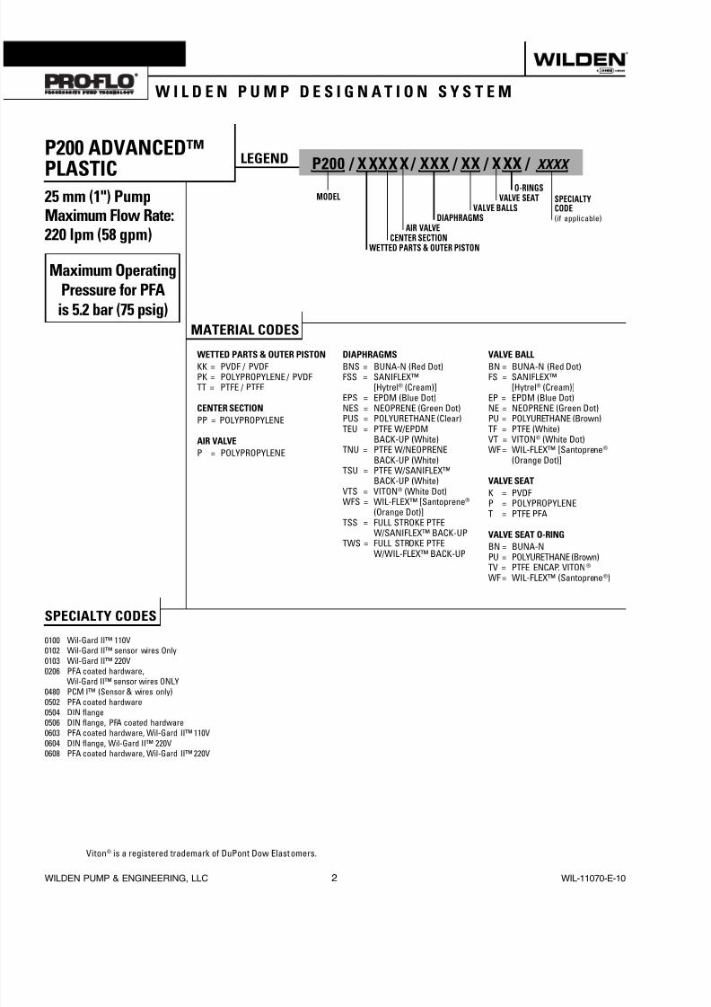
PLASTIC25 mm (1") PumpMaximum Flow Rate:220 lpm (58 gpm)
MATERIAL CODES
WETTED PARTS & OUTER PISTONKK = PVDF / PVDFPK = POLYPROPYLENE / PVDFTT = PTFE / PTFE
CENTER SECTIONPP = POLYPROPYLENE
AIR VALVEP = POLYPROPYLENE
DIAPHRAGMSBNS = BUNA-N (Red Dot)FSS = SANIFLEX™
[Hytrel® (Cream)]EPS = EPDM (Blue Dot)NES = NEOPRENE (Green Dot)PUS = POLYURETHANE (Clear)TEU = PTFE W/EPDM BACK-UP (White)TNU = PTFE W/NEOPRENE BACK-UP (White)TSU = PTFE W/SANIFLEX™ BACK-UP (White)VTS = VITON® (White Dot)WFS = WIL-FLEX™ [Santoprene®
(Orange Dot)]TSS = FULL STROKE PTFE W/SANIFLEX™ BACK-UPTWS = FULL STROKE PTFE W/WIL-FLEX™ BACK-UP
VALVE BALLBN = BUNA-N (Red Dot)FS = SANIFLEX™
[Hytrel® (Cream)]EP = EPDM (Blue Dot)NE = NEOPRENE (Green Dot)PU = POLYURETHANE (Brown)TF = PTFE (White)VT = VITON® (White Dot)WF = WIL-FLEX™ [Santoprene®
(Orange Dot)]
VALVE SEATK = PVDFP = POLYPROPYLENET = PTFE PFA
VALVE SEAT O-RINGBN = BUNA-NPU = POLYURETHANE (Brown)TV = PTFE ENCAP. VITON®
WF = WIL-FLEX™ (Santoprene®)
SPECIALTY CODES
0100 Wil-Gard II™ 110V0102 Wil-Gard II™ sensor wires Only0103 Wil-Gard II™ 220V0206 PFA coated hardware,
Wil-Gard II™ sensor wires ONLY0480 PCM I™ (Sensor & wires only)
0502 PFA coated hardware0504 DIN flange0506 DIN flange, PFA coated hardware0603 PFA coated hardware, Wil-Gard II™ 110V0604 DIN flange, Wil-Gard II™ 220V0608 PFA coated hardware, Wil-Gard II™ 220V
LEGEND P200 / X XXX X / XXX / XX / X XX / XXXX
O-RINGSMODEL VALVE SEAT
VALVE BALLSDIAPHRAGMS
AIR VALVECENTER SECTION
WETTED PARTS & OUTER PISTON
SPECIALTYCODE(if applicable)
Viton® is a registered trademark of DuPont Dow Elast omers.
Maximum OperatingPressure for PFAis 5.2 bar (75 psig)
S e c t i o n 2
W I L D E N P U M P D E S I G N A T I O N S Y S T E M

8/13/2019 p200 Adv Pls Eom 10
http://slidepdf.com/reader/full/p200-adv-pls-eom-10 5/28
WIL-11070-E-10 3 WILDEN PUMP & ENGINEERING, LLC
The Wilden diaphragm pump is an air-operated, positive displacement, self-priming pump. These drawings show the flow pattern through the pump upon its initial stroke. It is assumed the pump has no fluid in it prior to its initial stroke.
FIGURE 1 The air valve directs pressurized air to
the back side of diaphragm A. The compressedair is applied directly to the liquid column sepa-rated by elastomeric diaphragms. The diaphragmacts as a separation membrane between thecompressed air and liquid, balancing the load andremoving mechanical stress from the diaphragm.The compressed air moves the diaphragm awayfrom the center block of the pump. The oppositediaphragm is pulled in by the shaft connected tothe pressurized diaphragm. Diaphragm B is on itssuction stroke; air behind the diaphragm has beenforced out to the atmosphere through the exhaustport of the pump. The movement of diaphragmB toward the center block of the pump creates avacuum within chamber B. Atmospheric pressureforces fluid into the inlet manifold forcing the inletvalve ball off its seat. Liquid is free to move pastthe inlet valve ball and fill the liquid chamber (seeshaded area).
FIGURE 2 When the pressurized diaphragm,
diaphragm A, reaches the limit of its dischargestroke, the air valve redirects pressurized air to theback side of diaphragm B. The pressurized air forcesdiaphragm B away from the center block while pull-ing diaphragm A to the center block. Diaphragm Bis now on its discharge stroke. Diaphragm B forcesthe inlet valve ball onto its seat due to the hydraulicforces developed in the liquid chamber and mani-fold of the pump. These same hydraulic forceslift the discharge valve ball off its seat, while theopposite discharge valve ball is forced onto its seat,forcing fluid to flow through the pump discharge.The movement of diaphragm A toward the centerblock of the pump creates a vacuum within liquidchamber A. Atmospheric pressure forces fluid intothe inlet manifold of the pump. The inlet valve ball isforced off its seat allowing the fluid being pumpedto fill the liquid chamber.
FIGURE 3 At completion of the stroke, the air valve
again redirects air to the back side of diaphragm A,which starts diaphragm B on its exhaust stroke. Asthe pump reaches its original starting point, eachdiaphragm has gone through one exhaust and onedischarge stroke. This constitutes one completepumping cycle. The pump may take several cyclesto completely prime depending on the conditionsof the application.
The Pro-Flo ® patented air distributionsystem incorporates three moving parts:the air valve spool, the pilot spool, andthe main shaft/diaphragm assembly. Theheart of the system is the air valve spooland air valve. As shown in Figure A,this valve design incorporates an unbal-anced spool. The smaller end of the spoolis pressurized continuously, while thelarge end is alternately pressurized thenexhausted to move the spool. The spooldirects pressurized air to one air chamberwhile exhausting the other. The air causesthe main shaft/diaphragm assembly toshift to one side — discharging liquid onthat side and pulling liquid in on the otherside. When the shaft reaches the end of itsstroke, the inner piston actuates the pilotspool, which pressurizes and exhauststhe large end of the air valve spool. Therepositioning of the air valve spool routesthe air to the other air chamber.
Figure A
S e c t i o n 3
H O W I T W O R K S
H O W I T W O R K S — A I R D I S T R I B U T I O N S Y S T E M

8/13/2019 p200 Adv Pls Eom 10
http://slidepdf.com/reader/full/p200-adv-pls-eom-10 6/28
WILDEN PUMP & ENGINEERING, LLC 4 WIL-11070-E-10
6 mm (1/4") FNPT AIR INLET
13 mm(1/2") FNPT
AIR EXHAUST
DIMENSIONSITEM METRIC (mm) STANDARD (inch)
A 457 18.0B 66 2.6C 259 10.2D 381 15.0E 434 17.1F 99 3.9G 104 4.1H 122 4.8J 259 10.2K 231 9.1L 353 13.9
M 310 12.2N 124 4.9P 157 6.2R 10 0.4
DIN FLANGES 85 DIA. 3.3 DIA.T 115 DIA. 4.5 DIA.U 14 DIA. 0.6 DIA.
ANSI FLANGES 79 DIA. 3.1 DIA.T 108 DIA. 4.3 DIA.U 16 DIA. 0.6 DIA.
S e c t i o n 4
D I M E N S I O N A L D R A W I N G S
8/13/2019 p200 Adv Pls Eom 10
http://slidepdf.com/reader/full/p200-adv-pls-eom-10 7/28
WIL-11070-E-10 5 WILDEN PUMP & ENGINEERING, LLC
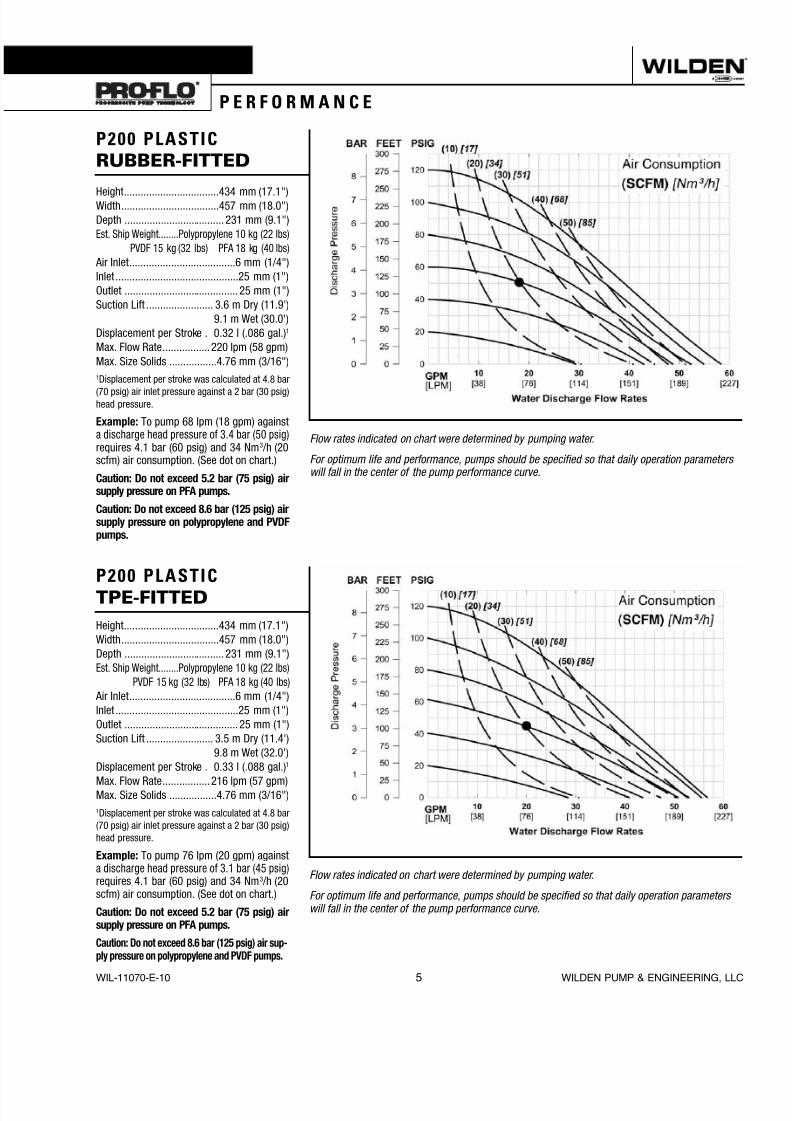
Height ..................................434 mm (17.1")Width ...................................457 mm (18.0")Depth .................................... 231 mm (9.1")Est. Ship Weight........Polypropylene 10 kg (22 lbs)
PVDF 15 kg (32 lbs) PFA 18 kg (40 lbs) Air Inlet ......................................6 mm (1/4")Inlet ............................................25 mm (1")Outlet ......................................... 25 mm (1")Suction Lift ........................ 3.6 m Dry (11.9')
9.1 m Wet (30.0')Displacement per Stroke . 0.32 l (.086 gal.) 1
Max. Flow Rate ................. 220 lpm (58 gpm)Max. Size Solids .................4.76 mm (3/16")1Displacement per stroke was calculated at 4.8 bar
(70 psig) air inlet pressure against a 2 bar (30 psig)head pressure.
Example: To pump 68 lpm (18 gpm) againsta discharge head pressure of 3.4 bar (50 psig) requires 4.1 bar (60 psig) and 34 Nm 3 /h (20scfm) air consumption. (See dot on chart.)
Caution: Do not exceed 5.2 bar (75 psig) airsupply pressure on PFA pumps.
Caution: Do not exceed 8.6 bar (125 psig) airsupply pressure on polypropylene and PVDFpumps.
Flow rates indicated on chart were determined by pumping water.
For optimum life and performance, pumps should be specified so that daily operation parameterswill fall in the center of the pump performance curve.
Height ..................................434 mm (17.1")Width ...................................457 mm (18.0")Depth .................................... 231 mm (9.1")Est. Ship Weight........Polypropylene 10 kg (22 lbs)
PVDF 15 kg (32 lbs) PFA 18 kg (40 lbs) Air Inlet ......................................6 mm (1/4")Inlet ............................................25 mm (1")Outlet ......................................... 25 mm (1")Suction Lift ........................ 3.5 m Dry (11.4')
9.8 m Wet (32.0')Displacement per Stroke . 0.33 l (.088 gal.) 1
Max. Flow Rate ................. 216 lpm (57 gpm)Max. Size Solids .................4.76 mm (3/16")1Displacement per stroke was calculated at 4.8 bar(70 psig) air inlet pressure against a 2 bar (30 psig)head pressure.
Example: To pump 76 lpm (20 gpm) againsta discharge head pressure of 3.1 bar (45 psig) requires 4.1 bar (60 psig) and 34 Nm 3 /h (20scfm) air consumption. (See dot on chart.)
Caution: Do not exceed 5.2 bar (75 psig) airsupply pressure on PFA pumps.
Caution: Do not exceed 8.6 bar (125 psig) air sup-ply pressure on polypropylene and PVDF pumps.
Flow rates indicated on chart were determined by pumping water.
For optimum life and performance, pumps should be specified so that daily operation parameterswill fall in the center of the pump performance curve.
S e c t i o n 5 A
P E R F O R M A N C E
P200 PLASTIC TPE-FITTED
P200 PLASTIC RUBBER-FITTED

8/13/2019 p200 Adv Pls Eom 10
http://slidepdf.com/reader/full/p200-adv-pls-eom-10 8/28
WILDEN PUMP & ENGINEERING, LLC 6 WIL-11070-E-10
Height ..................................434 mm (17.1")Width ...................................457 mm (18.0")Depth .................................... 231 mm (9.1")Est. Ship Weight ........Polypropylene 10 kg (22 lbs)
PVDF 15 kg (32 lbs) PFA 18 kg (40 lbs) Air Inlet ......................................6 mm (1/4")Inlet ............................................25 mm (1")Outlet ......................................... 25 mm (1")Suction Lift .......................... 2.4 m Dry (7.9')
9.4 m Wet (31.0')Displacement per Stroke . 0.22 l (.057 gal.) 1
Max. Flow Rate .................174 lpm (46 gpm)Max. Size Solids .................4.76 mm (3/16")1Displacement per stroke was calculated at 4.8 bar(70 psig) air inlet pressure against a 2.1 bar (30psig) head pressure.
Example: To pump 76 lpm (20 gpm) againsta discharge head pressure of 4.5 bar (65 psig) requires 6.9 bar (100 psig) and 37 Nm 3 /h(40 scfm) air consumption. (See dot onchart.)
Caution: Do not exceed 5.2 bar (75 psig) airsupply pressure on PFA pumps.
Caution: Do not exceed 8.6 bar (125 psig) airsupply pressure on polypropylene and PVDFpumps
Flow rates indicated on chart were determined by pumping water.
For optimum life and performance, pumps should be specified so that daily operation parameterswill fall in the center of the pump performance curve.
S e c t i o n 4
P E R F O R M A N C E
Height ..................................434 mm (17.1”)Width ...................................457 mm (18.0”)Depth .................................... 231 mm (9.1”)Ship Weight .....Polypropylene 10 kg (22 lbs.)..................................... PVDF 15 kg (32 lbs.)
Air Inlet ......................................6 mm (1/4”)Inlet ............................................25 mm (1”)Outlet ......................................... 25 mm (1”)Suction Lift ......................... 3.5m Dry (11.4’)..........................................8.6 m Wet (28.4’)Disp. Per Stroke ...................0.5 l (0.13 gal.) 1
Max. Flow Rate .............. 195 lpm (51.4 gpm)
Max. Size Solids .................4.76 mm (3/16”)1Displacement per stroke was calculated at4.8 bar (70 psig) air inlet pressure against a2.1 bar (30 psig) head pressure
Example: To pump 20 GPM against a dis-charge head of 60 psigrequires 80 psig and29 scfm air consumption.
Caution: Do not exceed 5.2 bar (75 psig) airsupply pressure on PFA pumps.
Caution: Do not exceed 8.6 bar (125 psig) airsupply pressure on polypropylene and PVDFpumps
Flow rates indicated on chart were determined by pumping water.
For optimum life and performance, pumps should be specified so that daily operation parameterswill fall in the center of the pump performance curve.
P200 PLASTIC FULL STROKE PTFE-FITTED
P200 PLASTIC REDUCED STROKE PTFE-FITTED

8/13/2019 p200 Adv Pls Eom 10
http://slidepdf.com/reader/full/p200-adv-pls-eom-10 9/28
WIL-11070-E-10 7 WILDEN PUMP & ENGINEERING, LLC
P 2 0 0 P L A S T I CS U C T I O N L I F T
C A PA B I L I T Y
26
24
22
20
18
16
14
12
10
8
6
4
2
0
7
6
5
4
3
2
1
00 10 20 30 40 50 60 70 80 90 100
[0.7] [1.4] [2.0] [2.7] [3.4] [4.1] [4.8] [5.5] [6.2] [6.9]
S e c t i o n 5 B
S U C T I O N L I F T C U RV E
Suction lift curves are calibrated for pumps operatingat 305 m (1,000') above sea level. This chart is meantto be a guide only. There are many variables whichcan affect your pump’s operating characteristics. The
number of intake and discharge elbows, viscosity ofpumping uid, elevation (atmospheric pressure) andpipe friction loss all affect the amount of suction liftyour pump will attain.

8/13/2019 p200 Adv Pls Eom 10
http://slidepdf.com/reader/full/p200-adv-pls-eom-10 10/28
WILDEN PUMP & ENGINEERING, LLC 8 WIL-11070-E-10
The Pro-Flo ® model P200 Advanced ™ plastic has a 25mm (1") inlet and 25 mm (1") outlet and is designed forflows to 220 lpm (58 gpm). The P200 Advanced ™ plasticpump is manufactured with wetted parts of pure, unpig-mented Polypropylene or PVDF. The P200 Advanced ™plastic pump is constructed with a glass fiber filled PP centersection. A variety of diaphragms and o-rings are availableto satisfy temperature, chemical compatibility, abrasion, andflex concerns.
The suction pipe size should be at least 25 mm (1") diameteror larger if highly viscous material is being pumped. Thesuction hose must be non-collapsible, reinforced type as theP200 Advanced ™ plastic pump is capable of pulling a highvacuum. Discharge piping should be at least 25 mm (1");larger diameter can be used to reduce friction losses. It iscritical that all fittings and connections are airtight or a reduc-tion or loss of pump suction capability will result.
INSTALLATION: Months of careful planning, study, andselection efforts can result in unsatisfactory pump perfor-mance if installation details are left to chance.
Premature failure and long term dissatisfaction can beavoided if reasonable care is exercised throughout the instal-lation process.
LOCATION: Noise, safety, and other logistical factors usuallydictate where equipment should be situated on the produc-tion floor. Multiple installations with conflicting requirementscan result in congestion of utility areas, leaving few choicesfor additional pumps.
Within the framework of these and other existing condi-tions, every pump should be located in such a way that fivekey factors are balanced against each other to maximumadvantage.
ACCESS: First, the location should be accessible. If it iseasy to reach the pump, maintenance personnel will have aneasier time carrying out routine inspections and adjustments.Should major repairs become necessary, ease of access canplay a key role in speeding the repair process and reducingtotal downtime.
AIR SUPPLY: Every pump location should have an air linelarge enough to supply the volume of air necessary to achievethe desired pumping rate (see Section 5). Do not exceed 5.2bar (75 psig) air supply for PFA pumps. Use air pressure upto a maximum of 8.6 bar (125 psig) for polypropylene andPVDF pumps depending on pumping requirements.
For best results, the pumps should use a 5µ (micron) air filter,needle valve and regulator. The use of an air filter before thepump will insure that the majority of any pipeline contami-nants will be eliminated.
SOLENOID OPERATION: When operation is controlled bya solenoid valve in the air line, three-way valves should beused, thus allowing trapped air to bleed off and improvingpump performance. Pumping volume can be set by count-ing the number of strokes per minute and multiplying bydisplacement per stroke.
SOUND: Sound levels are reduced using the standardWilden muffler element. Other mufflers can be used, butusually reduce pump performance.
ELEVATION: Selecting a site that is well within the pump’sdynamic lift capability will assure that loss-of-prime trou-bles will be eliminated. In addition, pump efficiency can beadversely affected if proper attention is not given to sitelocation.
PIPING: Final determination of the pump site should notbe made until the piping problems of each possible loca-tion have been evaluated. The impact of current and futureinstallations should be considered ahead of time to makesure that inadvertent restrictions are not created for anyremaining sites.
The best choice possible will be a site involving the shortestand straightest hook-up of suction and discharge piping.Unnecessary elbows, bends, and fittings should be avoided.Pipe sizes should be selected to keep friction losses withinpractical limits. All piping should be supported independentlyof the pump. In addition, the piping should be aligned toavoid placing stresses on the pump fittings.
Flexible hose can be installed to aid in absorbing the forcescreated by the natural reciprocating action of the pump. Ifthe pump is to be bolted down to a solid location, a mount-ing pad placed between the pump and the foundation willassist in minimizing pump vibration. Flexible connectionsbetween the pump and rigid piping will also assist in mini-mizing pump vibration. If quick-closing valves are installedat any point in the discharge system, or if pulsation within asystem becomes a problem, a surge suppressor should beinstalled to protect the pump, piping and gauges from surgesand water hammer.
The P200 Advanced™ plastic Pro-Flo ® equipped pumpcan be installed in submersible applications only whenboth the wetted and non-wetted portions are compatiblewith the material being pumped. If the pump is to be used
in a submersible application, a hose should be attached tothe air and pilot spool exhaust ports of the pump. Theseshould then be piped above the liquid level. The exhaustarea for the pilot spool is designed to be tapped for a 1/8"NPT fitting.
When pumps are installed in applications involving floodedsuction or suction head pressures, a gate valve should beinstalled in the suction line to permit closing of the line forpump service.
If the pump is to be used in a self-priming application, besure that all connections are airtight and that the suction-liftis within the ability of the model. Note: Materials of construc-tion and elastomer material have an effect on suction liftparameters. Please consult Wilden distributors for specifics.
Pumps in service with a positive suction head are most effi-cient when inlet pressure is limited to 0.5–0.7 bar (7–10 psig).Premature diaphragm failure may occur if positive suction is0.7 bar (10 psig) and higher.
THE MODEL P200 ADVANCED™ PLASTIC WILL PASS4.76 mm (3/16") SOLIDS. WHENEVER THE POSSIBILITYEXISTS THAT LARGER SOLID OBJECTS MAY BE SUCKEDINTO THE PUMP, A STRAINER SHOULD BE USED ON THESUCTION LINE.
CAUTION: DO NOT EXCEED 5.2 BAR (75 PSIG) AIRSUPPLY FOR PFA PUMPS. DO NOT EXCEED 8.6 BAR(125 PSIG) AIR SUPPLY PRESSURE FOR POLYPROPYL-ENE AND PVDF PUMPS.
S e c t i o n 6
S U G G E S T E D I N S T A L L AT I O N
8/13/2019 p200 Adv Pls Eom 10
http://slidepdf.com/reader/full/p200-adv-pls-eom-10 11/28
WIL-11070-E-10 9 WILDEN PUMP & ENGINEERING, LLC
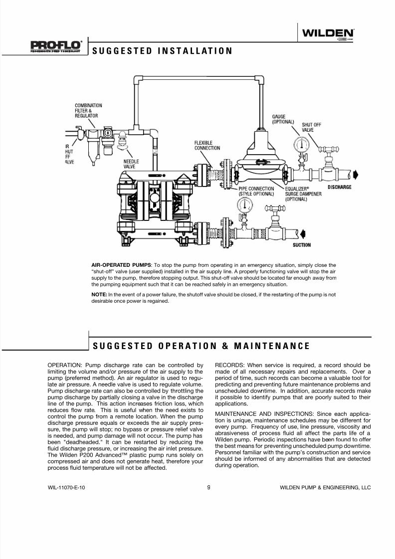
OPERATION: Pump discharge rate can be controlled bylimiting the volume and/or pressure of the air supply to thepump (preferred method). An air regulator is used to regu-late air pressure. A needle valve is used to regulate volume.
Pump discharge rate can also be controlled by throttling thepump discharge by partially closing a valve in the dischargeline of the pump. This action increases friction loss, whichreduces flow rate. This is useful when the need exists tocontrol the pump from a remote location. When the pumpdischarge pressure equals or exceeds the air supply pres-sure, the pump will stop; no bypass or pressure relief valveis needed, and pump damage will not occur. The pump hasbeen "deadheaded." It can be restarted by reducing thefluid discharge pressure, or increasing the air inlet pressure.The Wilden P200 Advanced™ plastic pump runs solely oncompressed air and does not generate heat, therefore yourprocess fluid temperature will not be affected.
RECORDS: When service is required, a record should bemade of all necessary repairs and replacements. Over aperiod of time, such records can become a valuable tool forpredicting and preventing future maintenance problems and
unscheduled downtime. In addition, accurate records makeit possible to identify pumps that are poorly suited to theirapplications.
MAINTENANCE AND INSPECTIONS: Since each applica-tion is unique, maintenance schedules may be different forevery pump. Frequency of use, line pressure, viscosity andabrasiveness of process fluid all affect the parts life of aWilden pump. Periodic inspections have been found to offerthe best means for preventing unscheduled pump downtime.Personnel familiar with the pump’s construction and serviceshould be informed of any abnormalities that are detectedduring operation.
AIR-OPERATED PUMPS : To stop the pump from operating in an emergency situation, simply close the“shut-off” valve (user supplied) installed in the air supply line. A properly functioning valve will stop the airsupply to the pump, therefore stopping output. This shut-off valve should be located far enough away fromthe pumping equipment such that it can be reached safely in an emergency situation.
NOTE: In the event of a power failure, the shutoff valve should be closed, if the restarting of the pump is notdesirable once power is regained.
S U G G E S T E D I N S TA L L AT I O N
S U G G E S T E D O P E R AT I O N & M A I N T E N A N C E

8/13/2019 p200 Adv Pls Eom 10
http://slidepdf.com/reader/full/p200-adv-pls-eom-10 12/28
WILDEN PUMP & ENGINEERING, LLC 10 WIL-11070-E-10
Pump will not run or runs slowly.1. Ensure that the air inlet pressure is at least 0.35 bar
(5 psig) above startup pressure and that the differentialpressure (the difference between air inlet and liquiddischarge pressures) is not less than 0.7 bar (10 psig).
2. Check air inlet filter for debris (see recommended instal-lation).
3. Check for extreme air leakage (blow by) which wouldindicate worn seals/bores in the air valve, pilot spool,main shaft.
4. Disassemble pump and check for obstructions in theair passageways or objects which would obstruct themovement of internal parts.
5. Check for sticking ball check valves. If material beingpumped is not compatible with pump elastomers, swell-ing may occur. Replace ball check valves and sealswith proper elastomers. In addition, valve balls becomesmaller as the wear. This may cause them to becomestuck in the seats. In this case, replace balls and seats.
6. Check for broken inner piston, which will prevent the airvalve spool from shifting.
7. Remove plug from pilot spool exhaust, check pilot spoolexhaust for blockage.
Pump runs but little or no product flows.1. Check for pump cavitation; slow pump speed down to
allow thick material to flow into liquid chambers.2. Verify that vacuum required to lift liquid is not greater
than the vapor pressure of the material being pumped(cavitation).
3. Check for sticking ball check valves. If material beingpumped is not compatible with pump elastomers, swell-ing may occur. Replace ball check valves and sealswith proper elastomers. In addition, valve balls becomesmaller as the wear. This may cause them to becomestuck in the seats. In this case, replace balls and seats.
Pump air valve freezes.1. Check for excessive moisture in compressed air. Install
either a dryer, or hot air generator for compressed air. Alternatively, a coalescing filter may be used to removethe water from the compressed air in some applica-tions.
Air bubbles in pump discharge.1. Check for ruptured diaphragm.
2. Check tightness of outer pistons.3. Check torque of bolts and integrity of o-rings and seals,
especially at intake manifold.4. Ensure pipe connections are airtight.
Product comes out air exhaust.1. Check for diaphragm rupture.2. Check tightness of outer pistons to shaft.
T R O U B L E S H O O T I N G

8/13/2019 p200 Adv Pls Eom 10
http://slidepdf.com/reader/full/p200-adv-pls-eom-10 13/28
WIL-11070-E-10 11 WILDEN PUMP & ENGINEERING, LLC
Figure 1
Step 2. Figure 2
Using the 13 mm (1/2”) box wrench, loosen the dischargemanifold from the liquid chambers.
Step 3. Figure 3
Remove the discharge manifold to expose the valve balls,valve seats and valve seat o-rings.
CAUTION: Before any maintenance or repair is attempted,the compressed air line to the pump should be discon-nected and all air pressure allowed to bleed from the pump.Disconnect all intake, discharge, and air lines. Drain thepump by turning it upside down and allowing any fluid toflow into a suitable container. Be aware of any hazardouseffects of contact with your process fluid.
TOOLS REQUIRED:13 mm (1/2") Box Wrench2 – 25 mm (1") Sockets or Adjustable Wrench
Adjustable Wrench Vise equipped with soft jaws (such as plywood, plasticor other suitable material)
NOTE: The model used for these instructions incorporatesPTFE diaphragms and balls. Models with rubber dia-phragms and balls are the same except where noted.
DISASSEMBLY:
Step 1.
Please see pre-molded alignment marks on the liquid chamberand center section.
S e c t i o n 7
P U M P D I S A S S E M B LY

8/13/2019 p200 Adv Pls Eom 10
http://slidepdf.com/reader/full/p200-adv-pls-eom-10 14/28
WILDEN PUMP & ENGINEERING, LLC 12 WIL-11070-E-10
Step 4. Figure 4
Remove the discharge valve balls, seats and valve seato-rings from the discharge manifold and liquid chamber,inspect for nicks, gouges, chemical attack or abrasivewear. Replace worn parts with genuine Wilden parts forreliable performance.
Step 5. Figure 5
Using a 13 mm (1/2") box wrench, remove the inlet mani-fold.
Step 6. Figure 6
Remove the inlet valve balls, seats andvalve seat o-rings from the liquid cham-ber and discharge manifold, inspectfor nicks, gouges, chemical attack orabrasive wear. Replace worn parts withgenuine Wilden parts for reliable perfor-mance.
Step 7. Figure 7
With a 13 mm (1/2") box wrench, removethe liquid chambers from the centersection.
Step 8. Figure 8
The liquid chamber should be removedto expose the diaphragm and outer pis-ton. Rotate center section and removethe opposite liquid chamber.
S e c t i o n 5 C
P U M P D I S A S S E M B LY

8/13/2019 p200 Adv Pls Eom 10
http://slidepdf.com/reader/full/p200-adv-pls-eom-10 15/28
WIL-11070-E-10 13 WILDEN PUMP & ENGINEERING, LLC
Step 9. Figure 9
Using two crescent wrenches or 25 mm (1") sockets, removediaphragm assembly from center section assembly.
Step 10. Figure 10
After loosening and removing the outer piston the diaphragmassembly can be disassembled.
Step 11. Figure 11
To remove the remaining diaphragmassembly from the shaft, secure shaft withsoft jaws (a vise fitted with plywood orother suitable material) to ensure shaft isnot nicked, scratched, or gouged. Usingan adjustable wrench, remove diaphragmassembly from shaft. Inspect all parts forwear and replace with genuine Wildenparts if necessary.
Step 12. Figure 12
Inspect diaphragms, outer and inner pis-tons for signs of wear. Replace with genu-ine Wilden parts if necessary.
S e c t i o n 5 C
P U M P D I S A S S E M B LY

8/13/2019 p200 Adv Pls Eom 10
http://slidepdf.com/reader/full/p200-adv-pls-eom-10 16/28
WILDEN PUMP & ENGINEERING, LLC 14 WIL-11070-E-10
Step 2. Figure 2
Remove muffler plate and air valve boltsfrom air valve assembly exposing muffler
gasket for inspection . Replace if neces-sary.
Step 3. Figure 3
Lift away air valve assembly and removeair valve gasket for inspection . Replace
if necessary.
Step 4. Figure 4
Remove air valve end cap to expose airvalve spool by simply lifting up on end
cap once air valve bolts are removed.
Step 1. Figure 1
Loosen the air valve bolts utilizing a 3/16" Allen wrench.
AIR VALVE DISASSEMBLY:
CAUTION: Before any maintenance or repair is attempted,the compressed air line to the pump should be discon-
nected and all air pressure allowed to bleed from the pump.Disconnect all intake, discharge, and air lines. Drain thepump by turning it upside down and allowing any fluid toflow into a suitable container. Be aware of hazardous effectsof contact with your process fluid.
The Wilden P200 Advanced™ Plastic Pump utilizes arevolutionary Pro-Flo ® air distribution system. A 6 mm(1/4") air inlet connects the air supply to the center sec-tion. Proprietary composite seals reduce the co efficient offriction and allow the P200 to run lube-free. Constructedof polypropylene, the Pro-Flo ® air distribution system isdesigned to perform in on/off, non-freezing, non-stalling,tough duty applications.
TOOLS REQUIRED:3/16" Allen WrenchSnap Ring PliersO-Ring Pick
S e c t i o n 5 C
D I S A S S E M B L Y , C L E A N I N G , & I N S P E C T I O N

8/13/2019 p200 Adv Pls Eom 10
http://slidepdf.com/reader/full/p200-adv-pls-eom-10 17/28
WIL-11070-E-10 15 WILDEN PUMP & ENGINEERING, LLC
Step 7. Figure 7
Remove pilot spool sleeve from centersection .
Step 8. Figure 8With o-ring pick, gently remove theo-ring from the opposite side of the“center hole” cut on the spool. Gentlyremove the pilot spool from sleeve andinspect for nicks or gouges and othersigns of wear. Replace pilot sleeveassembly or outer sleeve o-rings ifnecessary. During re-assembly neverinsert the pilot spool into the sleeve withthe “center cut” side first, this end incor-porates the urethane o-ring and will bedamaged as it slides over the ports cutin the sleeve.
NOTE: Seals should not be removedfrom pilot spool. Seals are notsold separately.
Step 9. Figure 9
Check center section Glyd™ rings forsigns of wear. If necessary, remove
Glyd™ rings with o-ring pick andreplace.
Step 5. Figure 5
Remove air valve spool from air valve body by threading oneair valve bolt into the end of the spool and gently sliding thespool out of the air valve body . Inspect seals for signs of wearand replace entire assembly if necessary. Use caution whenhandling air valve spool to prevent damaging seals.
NOTE: Seals should not be removed from assembly.Seals are not sold separately.
Step 6. Figure 6
Remove pilot spool sleeve retaining snap ring on both sidesof center section with snap ring pliers .

8/13/2019 p200 Adv Pls Eom 10
http://slidepdf.com/reader/full/p200-adv-pls-eom-10 18/28
WILDEN PUMP & ENGINEERING, LLC 16 WIL-11070-E-10
ASSEMBLY:Upon performing applicable maintenance to the air distributionsystem, the pump can now be reassembled. Please refer to
the disassembly instructions for photos and parts placement.To reassemble the pump, follow the disassembly instructions inreverse order. The air distribution system needs to be assem-bled first, then the diaphragms and finally the wetted path.Please find the applicable torque specifications on this page.The following tips will assist in the assembly process.
• Clean the inside of the center section shaft bore to ensureno damage is done to new seals.
• Stainless bolts should be lubed to reduce the possibility ofseizing during tightening.
• Be sure to tighten outer pistons simultaneously on PTFE-fitted pumps to ensure proper torque values.
• Apply two (2) drops of Loctite ® 246 to the shaft internalthreads before the diaphragm assembly.
• Concave side of disc spring in diaphragm assembly facestoward inner piston.
MAXIMUM TORQUE SPECIFICATIONSPart Description Torque
Pro-Flo® Air Valve 3.1 N•m (27 in-lbs)
Air Inlet Reducer Bushing 0.9 N•m (8 in-lbs)
Outer Piston (rubber, TPE, & PTFEdiaphragm tted)
27.1 N•m (20 ft-lbs)
Top & Bot tom Manifolds (Poly & PVDF) 5.6 N•m (50 in-lbs)
Liquid Chamber (Poly & PVDF) 8.5 N•m (75 in-lbs)
Top & Bottom Manifolds (PFA) 3.4 N•m (30 in-lbs)
Liquid Chamber (PFA) 5.6 N•m (50 in-lbs)
S e c t i o n 5 C
R E A S S E M B LY H I N T S & T I P S

8/13/2019 p200 Adv Pls Eom 10
http://slidepdf.com/reader/full/p200-adv-pls-eom-10 19/28
S e c t i o n 5 C
N O T E S
8/13/2019 p200 Adv Pls Eom 10
http://slidepdf.com/reader/full/p200-adv-pls-eom-10 20/28
WILDEN PUMP & ENGINEERING, LLC 18 WIL-11070-E-10
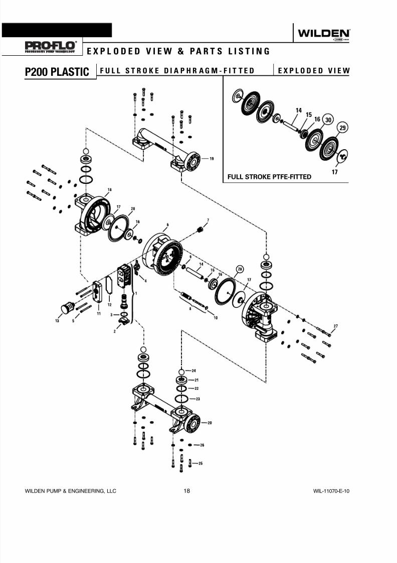
P200 PLASTIC F U L L S T R O K E D I A P H R A G M - F I T T E D E X P L O D E D V I E W
S e c t i o n 8
E X P L O D E D V I E W & PA R T S L I S T I N G
30
29
1514
16
17FULL STROKE PTFE-FITTED

8/13/2019 p200 Adv Pls Eom 10
http://slidepdf.com/reader/full/p200-adv-pls-eom-10 21/28
WIL-11070-E-10 19 WILDEN PUMP & ENGINEERING, LLC
Item Part Description
Qty.PerPump
P200/ PKPPPP/N
P200/ PKPPP/0502P/N
P200/ KKPPPP/N
P200/ KKPPP/0502P/N
1 Pro-Flo® Air Valve Assembly1 1 01-2010-20 01-2010-20 01-2010-20 01-2010-202 End Cap 1 01-2332-20 01-2332-20 01-2332-20 01-2332-203 O-Ring, End Cap 1 01-2395-52 01-2395-52 01-2395-52 01-2395-524 Gasket, Air Valve 1 01-2615-52 01-2615-52 01-2615-52 01-2615-525 Screw, HSHC, Air Valve 1/4-20 4 01-6001-03 01-6001-05 01-6001-03 01-6001-056 Center Section 1 02-3142-20 02-3142-20 02-3142-20 02-3142-207 Bushing, Reducer 1 01-6950-20 01-6950-20 01-6950-20 01-6950-208 Removable Pilot Sleeve Assembly 1 02-3880-99 02-3880-99 02-3880-99 02-3880-999 Glyd™ Ring II 2 02-3210-55-225 02-3210-55-225 02-3210-55-225 02-3210-55-210 Retaining Ring 2 00-2650-03 00-2650-03 00-2650-03 00-2650-0311 Muffler Plate 1 01-3181-20 01-3181-20 01-3181-20 01-3181-20
12 Gasket, Muffler Plate 1 01-3505-52 01-3505-52 01-3505-52 01-3505-5213 Muffler 1 02-3510-99 02-3510-99 02-3510-99 02-3510-9914 Shaft, Pro-Flo® 1 02-3810-03 02-3810-03 02-3810-03 02-3810-0315 Disc Spring (Belleville Washer) 2 02-6802-08 02-6802-08 02-6802-08 02-6802-0816 Inner Piston 2 02-3701-01 02-3701-01 02-3701-01 02-3701-0117 Outer Piston 2 02-4550-21-500 02-4550-21-500 02-4550-21-500 02-4550-21-50018 Liquid Chamber 2 02-5005-20 02-5005-20 02-5005-21 02-5005-2119 Discharge Manifold 1 02-5030-20 02-5030-20 02-5030-21 02-5030-2120 Inlet Manifold 1 02-5090-20 02-5090-20 02-5090-21 02-5090-2121 Valve Seat 4 02-1125-20 02-1125-20 02-1125-21 02-1125-2122 Valve Seat O-Ring 4 * * * *23 Flange O-Ring 4 * * * *24 Valve Ball 4 * * * *25 Flange Bolt 16 02-6181-03 02-6181-05 02-6181-03 02-6181-05
26 Washer 32 02-6731-03 02-6731-05 02-6731-03 02-6731-0527 Chamber Bolt 16 02-6191-03 02-6191-05 02-6191-03 02-6191-0528 Diaphragm 2 * * * *29 Diaphragm, Primary Full Stroke PTFE 2 02-1040-55 02-1040-55 02-1040-55 02-1040-5530 Diaphragm, Backup Full Stroke PTFE 2 * * * *
1 Air Valve Assembly includes items 2 and 3.*Refer to corresponding elastomer chart in Section 10.0502 Specialty Code = PFA Coated, ANSI Flange
All boldface items are primary wear parts.Consult Factory for DIN Flange.
E X P L O D E D V I E W & PA R T S L I S T I N G
P200 PLASTIC F U L L S T R O K E D I A P H R A G M - F I T T E D P A R T S L I S

8/13/2019 p200 Adv Pls Eom 10
http://slidepdf.com/reader/full/p200-adv-pls-eom-10 22/28
WILDEN PUMP & ENGINEERING, LLC 20 WIL-11070-E-10
S e c t i o n 5 C
E X P L O D E D V I E W & PA R T S L I S T I N G
P200 PLASTIC R E D U C E D S T R O K E D I A P H R A G M - F I T T E D E X P L O D E D V I E W
8/13/2019 p200 Adv Pls Eom 10
http://slidepdf.com/reader/full/p200-adv-pls-eom-10 23/28
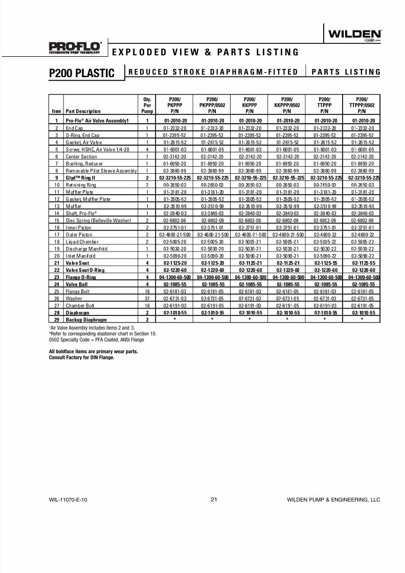
WIL-11070-E-10 21 WILDEN PUMP & ENGINEERING, LLC
Item Part Description
Qty.PerPump
P200/ PKPPPP/N
P200/ PKPPP/0502P/N
P200/ KKPPPP/N
P200/ KKPPP/0502P/N
P200/ TTPPPP/N
P200/ TTPPP/0502P/N
1 Pro-Flo® Air Valve Assembly1 1 01-2010-20 01-2010-20 01-2010-20 01-2010-20 01-2010-20 01-20102 End Cap 1 01-2332-20 01-2332-20 01-2332-20 01-2332-20 01-2332-20 01-2332-23 O-Ring, End Cap 1 01-2395-52 01-2395-52 01-2395-52 01-2395-52 01-2395-52 01-2395-54 Gasket, Air Valve 1 01-2615-52 01-2615-52 01-2615-52 01-2615-52 01-2615-52 01-2615-55 Screw, HSHC, Air Valve 1/4-20 4 01-6001-03 01-6001-05 01-6001-03 01-6001-05 01-6001-03 01-6001-06 Center Section 1 02-3142-20 02-3142-20 02-3142-20 02-3142-20 02-3142-20 02-3142-207 Bushing, Reducer 1 01-6950-20 01-6950-20 01-6950-20 01-6950-20 01-6950-20 01-6950-208 Removable Pilot Sleeve Assembly 1 02-3880-99 02-3880-99 02-3880-99 02-3880-99 02-3880-99 02-3880-999 Glyd™ Ring II 2 02-3210-55-225 02-3210-55-225 02-3210-55-225 02-3210-55-225 02-3210-55-225 02-32110 Retaining Ring 2 00-2650-03 00-2650-03 00-2650-03 00-2650-03 00-2650-03 00-2650-011 Muffler Plate 1 01-3181-20 01-3181-20 01-3181-20 01-3181-20 01-3181-20 01-3181-20
12 Gasket, Muffler Plate 1 01-3505-52 01-3505-52 01-3505-52 01-3505-52 01-3505-52 01-3505-5213 Muffler 1 02-3510-99 02-3510-99 02-3510-99 02-3510-99 02-3510-99 02-3510-914 Shaft, Pro-Flo® 1 02-3840-03 02-3840-03 02-3840-03 02-3840-03 02-3840-03 02-3840-0315 Disc Spring (Belleville Washer) 2 02-6802-08 02-6802-08 02-6802-08 02-6802-08 02-6802-08 02-6802-0816 Inner Piston 2 02-3751-01 02-3751-01 02-3751-01 02-3751-01 02-3751-01 02-3751-0117 Outer Piston 2 02-4600-21-500 02-4600-21-500 02-4600-21-500 02-4600-21-500 02-4600-22 02-4600-218 Liquid Chamber 2 02-5005-20 02-5005-20 02-5005-21 02-5005-21 02-5005-22 02-5005-219 Discharge Manifold 1 02-5030-20 02-5030-20 02-5030-21 02-5030-21 02-5030-22 02-5030-2220 Inlet Manifold 1 02-5090-20 02-5090-20 02-5090-21 02-5090-21 02-5090-22 02-5090-221 Valve Seat 4 02-1125-20 02-1125-20 02-1125-21 02-1125-21 02-1125-55 02-112522 Valve Seat O-Ring 4 02-1220-60 02-1220-60 02-1220-60 02-1220-60 02-1220-60 02-122023 Flange O-Ring 4 04-1300-60-500 04-1300-60-500 04-1300-60-500 04-1300-60-500 04-1300-60-500 04-130024 Valve Ball 4 02-1085-55 02-1085-55 02-1085-55 02-1085-55 02-1085-55 02-108525 Flange Bolt 16 02-6181-03 02-6181-05 02-6181-03 02-6181-05 02-6181-03 02-6181-0
26 Washer 32 02-6731-03 02-6731-05 02-6731-03 02-6731-05 02-6731-03 02-6731-0527 Chamber Bolt 16 02-6191-03 02-6191-05 02-6191-03 02-6191-05 02-6191-03 02-6191-0528 Diaphragm 2 02-1010-55 02-1010-55 02-1010-55 02-1010-55 02-1010-55 02-101029 Backup Diaphragm 2 * * * * * *
1 Air Valve Assembly includes items 2 and 3.*Refer to corresponding elastomer chart in Section 10.0502 Specialty Code = PFA Coated, ANSI Flange
All boldface items are primary wear parts.Consult Factory for DIN Flange.
E X P L O D E D V I E W & PA R T S L I S T I N G
P200 PLASTIC R E D U C E D S T R O K E D I A P H R A G M - F I T T E D PA R T S L I S T I N

8/13/2019 p200 Adv Pls Eom 10
http://slidepdf.com/reader/full/p200-adv-pls-eom-10 24/28
WILDEN PUMP & ENGINEERING, LLC 22 WIL-11070-E-10
P200 Advanced Plastic Pumps
Material
Color
Code
Diaphragm (2)
P/N
Valve Ball (4)
P/N
Valve SeatO-Ring (4)
P/N
FlangeO-Ring (4)
P/N
Reduced StrokeBackup Diaphragm (2)
P/N
Full StrokeBackup Diaphragm (2)
P/NPolyurethane Natural 02-1010-50 02-1085-50 02-1220-50 04-1300-50-500 N/A N/A
Buna-N Red 02-1010-52 02-1085-52 04-2390-52-700 04-1300-52-500 N/A N/APTFE Encapsulated Viton ® None N/A N/A 02-1220-60 04-1300-60-500 N/A N/A
Neoprene Green 02-1010-51 02-1085-51 N/A N/A 02-1060-51 N/AViton® Silver 02-1010-53 02-1085-53 N/A N/A N/A N/A
EPDM Blue 02-1010-54 02-1085-54 N/A N/A 02-1060-541 N/APTFE - Reduced Stroke White 02-1010-55 02-1085-55 N/A N/A N/A N/A
Full Stroke PTFE 02-1040-55 02-1085-55 N/A N/A N/A N/A
Tetra-Flex™ PTFEw/Neoprene White 02-1010-64 N/A N/A N/A N/A N/A
Tetra-Flex™ PTFEw/EPDM White 02-1010-81 N/A N/A N/A N/A N/A
Saniflex™ Off-White 02-1010-56 02-1085-56 N/A N/A 02-1060-561 02-1065-56Wil-Flex™ Orange 02-1010-58 02-1085-58 02-1220-58 02-1370-58 N/A 02-1065-57
1Saniflex™ and EPDM back-up diaphragms are available upon request. Please consult your local distributor.Backup diaphragms for use with PTFE diaphragms only.
S e c t i o n 9
E L A S T O M E R O P T I O N S

8/13/2019 p200 Adv Pls Eom 10
http://slidepdf.com/reader/full/p200-adv-pls-eom-10 25/28
S e c t i o n 5 C
N O T E S

8/13/2019 p200 Adv Pls Eom 10
http://slidepdf.com/reader/full/p200-adv-pls-eom-10 26/28
S e c t i o n 5 C
N O T E S

8/13/2019 p200 Adv Pls Eom 10
http://slidepdf.com/reader/full/p200-adv-pls-eom-10 27/28
Item # Serial #
Company Where Purchased
Company Name
Industry
Name Title
Street Address
City State Postal Code Country
Telephone Fax E-mail Web Address
Number of pumps in facility? Number of Wilden pumps?
Types of pumps in facility (check all that apply): Diaphragm Centrifugal Gear Submersible Lobe
Other
Media being pumped?
How did you hear of Wilden Pump? Trade Journal Trade Show Internet /E-mail Distributor
Other
P U M P I N F O R M AT I O N
PLEASE PRINT OR TYPE AND FAX TO WILDEN
Y O U R I N F O R M AT I O N
ONCE COMPLETE, FAX TO (909) 783-3440NOTE: WARRANTY VOID IF PAGE IS NOT FAXED TO WILDEN
WILDEN PUMP & ENGINEERING, LLC
W A R R A N T Y
Each and every product manufactured by Wilden Pump and Engineering, LLC is built to meet the higheststandards of quality. Every pump is functionally tested to insure integrity of operation.
Wilden Pump and Engineering, LLC warrants that pumps, accessories and parts manufactured or supplied byit to be f ree from defects in material and workmanship for a period of ve (5) years f rom date of installation or
six (6) years from date of manufacture, whichever comes rst. Failure due to normal wear, misapplication, orabuse is, of course, excluded from this warranty.
Since the use of Wilden pumps and parts is beyond our control, we cannot guarantee the suitability of any pumpor part for a par ticular application and Wilden Pump and Engineering, LLC shall not be liable for any consequentialdamage or expense arising from the use or misuse of its products on any application. Responsibility is limitedsolely to replacement or repair of defective Wilden pumps and parts.
All decisions as to the cause of failure are the sole determination of Wilden Pump and Engineering, LLC.
Prior approval must be obtained from Wilden for return of any items for warranty consideration and must beaccompanied by the appropriate MSDS for the product(s) involved. A Return Goods Tag, obtained from anauthorized Wilden distributor, must be included with the items which must be shipped freight prepaid.
The foregoing warranty is exclusive and in lieu of all other warranties expressed or implied (whether written or oral)including all implied warranties of merchantability and tness for any particular purpose. No distributor or otherperson is authorized to assume any liability or obligation for Wilden Pump and Engineering, LLC other than expresslyprovided herein.

8/13/2019 p200 Adv Pls Eom 10
http://slidepdf.com/reader/full/p200-adv-pls-eom-10 28/28
Your Local Authorized Distributor:
Enrich Your Process
Simplicity of design
Unique Technology
Reliable, leak-free & quiet
Validated & certified
Intrinsically safe The result of unique thought
Advance Your Process
Advanced wetted path designs
Lower the cost of operation
Maximize product containment
Longer MTBF(Mean Time Between Failures)
Enhanced internal clearance The result of advanced thought
Refine Your Process
Designed for sanitary applications Minimize product degradation
Improved production yields
Easy to inspect, clean & assemble
Minimized water requirements
The result of progressive thought
Simplify Your Process
Maximize Your Process
Electronic control & monitoring Level control & containment
Pulsation dampening
Drum unloading systems
Complete system solutions
The result of innovative thought
Simplify Your Process
Long standing design simplicity
Portable & submersible
Variable connection options
Fewest parts in industry
Solutions since 1955
The result of original thought