p12xenbr_Lm Tech Spec
12
MiCOM P120, P121, P122 and P123 Universal Overcurrent Relays T & D Energy Automation & Information MiCOM P120, P121, P122 and P123 : Universal Overcurrent Relays
-
Upload
rindarayna -
Category
Documents
-
view
17 -
download
0
Transcript of p12xenbr_Lm Tech Spec

MiCOM P120, P121, P122 and P123Universal Overcurrent Relays
T & DEnergy Automation & Information
MiCOM P120, P121, P122 and P123 :
Universal Overcurrent Relays

2
MiCOM P120, P121, P122 and P123A whole range for a global answer
MiCOM P12x relays providesimple and powerful operatorinterface. The LEDs and LCDdisplay on the front panel are fullyprogrammable to userrequirements.
True RMS current and frequencyvalues are measured by all theMiCOM P12x relays.Measurements are displayed on thefront panel and are available forlocal viewing and remotetransmission.
For each MiCOM P12x relay,inputs and outputs are freelyassignable and combinations ofany thresholds are independentlyprogrammable for each output.
Setting software MiCOM S1combined with the front and rearcommunication ports allow the usereasy access to all storedinformation and ouput of operatingcurves or parameter trends.
The MiCOM P120, P121, P122,P123 relays are housed in thesame drawout 4U metal case forpanel or rack mounting.
The use of MIDOS connectorsallows full compatibility withexisting ALSTOM devices.
CT inputs of any relay of theMiCOM P12x series are 1 and 5Amp dual rated.
DescriptionThe MiCOM P12x series are theuniversal overcurrent relay rangefor ALSTOM. Starting with thesingle phase P120 up to themultifunction three phases andearth P123, MiCOM relays arefully designed to protect andcontrol industrial plants, utilitiessubstations and networks at anyvoltage level.
Protection features of the MiCOM P12x range include 3independent phase overcurrentstages, 3 independent earthovercurrent stages, 12 selectablecurve characteristics, thermaloverload protection, undercurrentand negative-sequence overcurrentprotection.
Flexible automation functionsenable accurate co-ordination withother devices.
Circuit-breaker monitoring isperformed through closing andopening time measurements,breaker failure protection and tripcircuit supervision.
Two setting groups accomodatecomplex protection and controlschemes. Setting commutation isavailable locally or remotely.
The MiCOM P12x relays are fullycompatible with a wide range ofstandard communication protocols(MODBUSTM, IEC 60870-5-103,etc.).
All the information in memory suchas settings, measurements, events,fault or disturbance records areeasily transmitted for better networkmanagement. Remote systemrequests are immediately executedand transmitted to the adjacentswitchgear.
Single phase or earth o/c
3 phases + earth o/c
Advanced 3 phases + earth o/c
Expert 3 phases + earth o/c
P121
P120
P122
P123

3
Functions ANSI MiCOM MiCOM MiCOM MiCOMcodes P120 P121 P122 P123
Single phase or Earth overcurrent 50/51 or X
3 independant stages 50N/51N
Three phase and Earth overcurrent 50/51 and X X X
3 independant stages 50N/51N
High Impedance Restricted Earth Fault 64N X X X X
Thermal overload (True RMS) 49 X X
Undercurrent 37 X X
Negative phase sequence overcurrent 46 X X
2 independant stages
Broken conductor detection (I2/I1) X X
Clock phase and anti-clock phase X X
rotation operation
Cold load pickup X X
Output relay latching 86 X X X X
Setting groups 1 1 2 2
Circuit breaker failure detection 50BF X X
Circuit breaker monitoring X X
Trip circuit supervision X X
Blocking logic X X X X
Selective relay scheme logic X X
Autoreclose (4 shots) 79 X
Measurements (True RMS values) X X X X
Peak and rolling values X X
Instantaneous records X X
Event records X X
Fault records X X
Disturbance records X X
Communication X X X X
Models available
Protection and control
Time-delayed phaseovercurrent (51)
The MiCOM P12x relays providethree phase current inputs (exceptfor the single phase P120 relay).
Three independent stages relay areavailable. For the first stage, theuser may select between 12different shapes of curves(IEEE/ANSI, IEC, RI, RC).
For each curve model, a wideselection of 60 different TMS valuescan be set to optimise detection andshorten tripping time for co-ordination with fuses, motors,feeders, transformers and otherdevices.
The second and third stages haveindependent settings with anadjustable definite time tripping.The time delays are programmablefrom 0 to 150 s thus providingmaximum selectivity.
The phase current range isadjustable independently for eachstage from 0.1 to 40 times therated phase current (0.002 to 40In for the MiCOM P120 model).
All the phase overcurrent settingsare fully programmable using thefront panel HMI, the SettingSoftware front connection or aremote communication controlsystem (e.g. MiCOM S10).

4
Instantaneous phaseovercurrent (50)The MiCOM P12x relays haveseparate phase instantaneousovercurrent information for eachselected stage.
Phase instantaneous trips (with notime delay programmed) areavailable in less than 30 ms.
Each instantaneous trip is fullyassignable to any dedicated outputof the MiCOM relays and/or on thefront panel LEDs.
Time-delayed earth-faultovercurrent (51N)Earth fault detection in the MiCOM P12x range is identical tothe time-delayed phase overcurrent.
Three independent earth-fault stagesare selectable. The user can selectany of the 14 families of curvesand TMS values for the first stage.
Earth current range is adjustable foreach stage from 0.002 to 40 timesthe rated earth current to allowmaximum sensitivity for earth faultdetection.
The earth current input is usuallygenerated by a dedicated earth CTbut may also be derived from theresidual connection of the 3 line CTs.
Instantaneous earth-faultovercurrent (50N)All instantaneous earth fault stagesare fully available. As with theinstantaneous phase fault feature,the instantaneous earth stages areavailable in less than 30 ms.
These indications are assignable toany outputs and/or LEDs on theMiCOM relay front panel.
High impedance restrictedearth-fault (64N)MiCOM P12x range offer the REFfeature applied to enhanced groundfault detection on each transformerwinding.The relays ensure a high degree ofstability against external faultconditions and a reliableperformance against insternal faults.All the stages can be used for thisapplication.
Negative sequenceovercurrent (46)The MiCOM P122 & P123 relaysinclude a programmable functionspecially designed to detectunbalanced fault conditions whenearth fault elements are notoperated or not sufficiently sensitive.Two independant stages areselectable. Instantaneous and time-delayed (DT or IDMT) negativesequence overcurrent stages havethe same functions as the phaseovercurrent and earth-fault settings.
Broken conductorOne type of unbalanced fault whichcan occur on the system is an opencircuit fault. This can arise frombroken conductors, maloperation ofsingle phase switchgear, or theblowing of fuses. MiCOM P122 and P123 relaysincorporate an element whichmeasures the ratio of negative topositive sequence current (I2/I1).This fully programmable functionallows more sensitivity thannegative sequence overcurrentdetection.
Figure 2: MiCOM P122 and P123broken conductor detection.
Thermal overload (49)Transformers and cables must beprotected to account for theirparticular thermal characteristics.MiCOM P122 and P123 relaysinclude a thermal overload elementbased on the true RMS value of thecurrent. Alarm and overloadthresholds are fully programmableto match each device requirement.
Undercurrent (37)MiCOM P122 and P123 relaysprovide an undercurrent function.This function allows typicalapplications such as loss of load,circuit breaker failure or simplebroken conductor detection.
Blocking logicWhen MiCOM P12x relays areused in critical networks,management of protection relaysmust take surrounding devices intoconsideration.Two blocking inputs can beconfigured independently from eachother to block any combination ofthe user selected elements (e.g.current elements, thermal overload,etc.). Each blocking signal freezesits associated memory (timer orthermal state) and, after drop off,re-imposes the pre-blocking value ifconditions are still present.
Cold load pickup
100
200
300
400
0 1 2 3 4 5 6 Time (s)
Curr
ent (
% o
f nom
inal
)
Nominal threshold Figure 3:Typical cold load current.
Figure 1: Phase overcurrent characteristics
I >>> t >>>
t >>I >>
t >
I >
Ith
I<
Current
Tim
e
When a feeder is loaded after along outage, all connected devicessuch as transformers will call for anover energisation current, over thenominal setting, during a short time.To prevent unwanted tripping,MiCOM P122 and P123 have acold load pickup function whichautomatically increases the standardsettings during a dedicatedadjustable time. After a successfulclose, all settings are returned totheir nominal values.

5
Autorecloser (79)MiCOM P123 relays include a 4-shot autorecloser with oneinstantaneous and three time-delayed reclose shots. All theprogrammed protection functionsmay start any of the shotsindependently and the user canprogram which functions areallowed to trip after any of theshots. Dead and reclaim times arefreely adjustable. Associated LEDscan be programmed on the frontLCD display of the MiCOM relay.
A counter stores the number ofreclose commands, incrementedwith each reclose order. Thisinformation can be displayedlocally or remotely.
Selective relay scheme logicReduction of supply outages is aprimary objective in any electricalnetwork. To help the user reducethese non-quality factors, MiCOMP122 and P123 relays includeselective relay scheme logic.
A dedicated input can temporarilyalter the time-delay settings inresponse to a downstream relayphase/earth fault start condition.This function allows the MiCOMrelays to discriminate correctlywhen used in a cascade scheme.
The selective relay scheme logicfunction can be enabled ordisabled by the user as required.
Monitoring functionsand measurements
Circuit-breaker maintenanceCircuit-breaker preventivemaintenance is the advancedfunction provided by the MiCOM P122 and P123 relayswith adjustable closing andopening time measurements andbreaker failure protection.
All phase currents I and I2 duringfaults are memorised and summed.
The MiCOM P122 & P123 relaysallow trip circuit supervision via aspecific input. The result of thismonitoring can be viewed locally orremotely. Figure 4: MiCOM P122 settings in
MiCOM S1 support software
MeasurementsThe MiCOM P12x relays monitorpermanently all the current inputs,calculate the frequency and the linecurrents, display the values on theLCD display and store themeasurements into memory.
The calculation of the averagevalue for each phase during aselectable rolling sub-period is alsoavailable.
The measured values are true RMSup to the 10th harmonic with a0.1% accuracy (nominalconditions). Peak demands with a15-minute window are alsomemorised.
All the measured and derivedvalues can be displayed on thefront panel LCD or transferredlocally or remotely upon userrequest.
Instantaneous recording
Five instantaneous logs are storedin the MiCOM P122 & P123relays.
Each instantaneous record includes:
• instantaneous time (date & duration)
• origin (phase & earth threshold)Instantaneous records give the useruseful information for preventivemaintenance of the electricalsystem.
Event recording
75 logic events are stored in theMiCOM P122 and P123 relays.Events include inputs/outputs, statechanges, alarms and contactoperations.
All events are time-tagged to 1ms.
Setting groupsExternal conditions may call theneed for several setting groups. The MiCOM P122 and P123 relayshave two selectable setting groupsincluding all the protection,automation features and monitoringfunctions.
Commutation between groups 1 and2 can be achieved locally, remotelyor via a dedicated logic input.
Transition from one setting group to the other is achieved only if noprotection or automation function is running to prevent unwantedtripping.
Programmable inputs andouputsMiCOM P12x relays include up to 5logic inputs and 9 logic outputsincluding a watch-dog. All inputsand outputs are freely configurable.
Two of the outputs are change-overtype typically used for trippingcommands.
All programmed thresholds (time- delayed or instantaneous) caneasily be combined onto any of theoutputs.
Output relay latching (86)Any of the outputs, including trip,can be latched.Reset of the outputs is possible froma logic input, the front paneloperator interface or through theremote communications.
Circuit breaker failureprotection (50BF) The circuit breaker failure protectionverifies the effective opening of theCB by a dedicated undercurrentthreshold during a t_BF timer.
The circuit breaker failure function isactivated by the trip of a genericprotection.
Circuit breaker failure protectionmay be used for tripping upstreamcircuit breakers.
6
User interface
Front display and menusAll functions including protectionautomation, communication, LEDs,inputs and outputs can beprogrammed and modified usingthe front panel user interface.
The 32 alphanumerical backlit LCDdisplay (available in a range oflanguages) provides the user withkey information (faults,measurements, settings, etc.).
The menus have a pull-downstructure for easy use and quickaccess to any data.
Dedicated LEDs4 LEDs indicate the state of theMiCOM relays (Trip, Alarm,Warning, Healthy).
Acknowledgement of alarm and tripLEDs can be easily performedlocally or remotely.
Programmable LEDs4 freely programmable LEDs areprovided on all models of theMiCOM P12x series. The user can assign independentlyeach LED to any program functionor combination of thresholds.
KeypadA seven-button tactile keypad on thefront panel allows the user easyaccess to any data in the MiCOM P12x relays.
Communication EIA RS485All models of MiCOM P12x serieshave an EIA RS485 communicationsrear port. This port is available for MODBUSTM, Courier, IEC 60870-5-103, or DNP3protocols. MiCOM relays cantransmit to the local monitoringsystem (e.g. MiCOM S10), orremotely to the SCADA, settings,measurements and alarms, as wellas fault, event and disturbancerecords.
The communications settings (relayaddress, data rate, parity, etc.) canbe programmed using the HumanMachine Interface of the relay.
Communication EIA RS232An EIA RS232 front port isavailable in the MiCOM P12x series.
It allows the user to download anew firmware (update, languagechanging,...) and the link with thesetting software MiCOM S1 (P122 & P123 only).
MiCOM S1support software A dedicated ALSTOM SupportSoftware MiCOM S1 is availablefor the MiCOM P12x relays toallow easy use.
Fully WindowsTM compatible (98 and NT4.0), the SupportSoftware allows easy setting of anyMiCOM P12x model, in addition touploading of event, fault anddisturbance records, settings andmeasurements.
File Configuration Analysis Calculation Window ?
Disturbance Record Analysis
Figure 5: P123 Disturbance record analysis
Figure 6: MiCOM P12x front panel
Disturbance recordingCurrent waveforms are captured bythe MiCOM P122 and P123 relaysat a sampling frequency of 1600Hz.Up to 3 seconds of records arestored inside the relays. The disturbance recording functionis triggered either by any of theprogrammed thresholds or by anexternal input, or through thecommunications.
All logic and analogue informationis stored in memory and can betransferred using the frontcommunication port or the rear LANto an external data analyser.
Fault recordsFive faults are stored inside theMiCOM relays. Each recordincludes:
• Fault indicators
• Current values
• Tripping time
Fault indications help the useridentify clearly the fault and monitorthe MiCOM P122 and P123 relays’settings.

7
HardwareMiCOM P12x models arenumerical protection and controlrelays.
CaseFor all models of the MiCOM P12xseries (P120, P121, P122 andP123), the unit has a drawout metal4U case. All the CT inputs are short-circuited if the active unit iswithdrawn from its case. All MiCOM relays can be panel orrack-mounted.
WiringExternal connections are made viaMIDOS type terminal blocks. Eachconnection includes two 6.35mmFaston and one M4 screw fixing.
The wiring for all the MiCOMP120, P121, P122 and P123relays is standard so as to providemaximum compatibility.
22625.1
Side view, flush mounting
151.2 max.
7851.8
10.5
158168
23.6
All dimensionsin mm.
Panel cut-out flush mountingfixing details
99 4 holes Ø 4.4 (M4 screw)
103 (20 TE)
Trip .
Alarme
Equip.Fail
Auxilliarysupply
AUX. 1
AUX. 2
AUX. 3
AUX. 4
C
MiCOM P121
IA = 214.50 A
177
Front view
4 holes Ø 3.4
Figure 7: MiCOM S10 control system.
Figure 12: Size 20 TECase outlines
8
Auxiliaryvoltage
Programmableinput
Phase rotationC B
29
Port communication
Communicationcable shield
CT shorting links make before (b) and (c) disconnect
(3) Earth terminals are typical only(2) CT connection are typical only
Nota :(1)
(c)
(a)
(b) Short terminals break before (c)
Long terminals
last relay to be connected( : terminating resistor for the*
30
32
*31 _
+
Case earth connection
Programmable output
Programmable trippingoutput
34
P120/P121MiCOM
26
28
24
22
L2
L1
RL4
RL2
RL3
RL1
20
18
108
16
14
12
24
33+
_ 6
Module terminal blocks
(with integral case earth link)
viewed fromp rear
Case earth
Pins terminals (pcb type)(d)
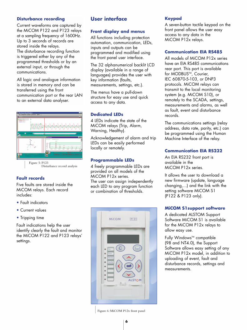
Alternative : The earth current input is connected to the sommation of the three phase CTs.
C
A
B
S1S2
S2
P2 P1 P2 37
S1
P1
5 A
5 A
5 A
5 A
1 A
1 A
48
4746
4544
4342
4156
5554
5253
1 A
1 A5051
49
inputProgrammable
Programmable output
Programmable output
The current inputs are connected to 3 phase CTs + a core balanced CT.
between 30-32)
+
-+
-
(4) Change over contact from Hardware version 4 only
47
55
53
4951
37
45434139
3533
2931
48
56
545250
38
46444240
36343230
2423
27
25
28
26
21
2119
1517
13
2220
1618
14
7
911
53
8
1210
64
only
C
A
B
P2
S2 S1
P1
5 A
48
5 A
4746
4544
5 A
5 A
4342
4156
1 A
1 A
5554
5352
1 A51
1 A50
49
P121
onlyP121
P121
P121
A
Alternative (P121 only): Connection to 2 phases CTs + a core balanced CT.
B
C S2
AP2 P1 P2
S1
S2 S1
P1
41
5 A
5 A
4342
1 A
1 A
56
5554
1 A
1 A
5352
5150
49
45
48
5 A
5 A
4746
44
WD3635 Watch dog (4)
EIA RS485
Figure 8:Typical application diagram M
iCO
M P120/P121.
Scheme representing MiCOM relay off

9
36Auxiliaryvoltage
Programmableinput
Phase rotationC B
29 L3
CT shorting links make before (b) and (c) disconnect
(3) Earth terminals are typical only(2) CT connection are typical only
Nota :(1)
(c)
(a)
(b)
23
27
25 21
19
L5
L4
Short terminals break before (c)
Long terminals
last relay to be connected( : terminating resistor for the*
30
32
*31
Programmable output
Programmable tripping
Watch dog (4)
output
34
P122/P123MiCOM
26
17
28
24
22
L2
L1
RL7
RL813
15
11
RL6
RL5
RL4
RL2
RL3
RL1
5
9
7
1
3
20
18
108
16
14
12
24
33+
_ WD
6
35
Module terminal blocks
(with integral case earth link)
viewed from rear
Pins terminals (pcb type)(d)
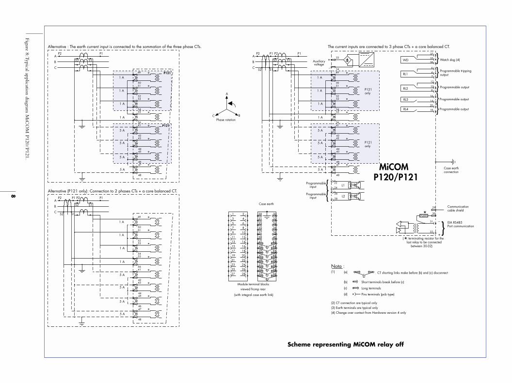
Alternative : The earth current input is connected to the sommation of the three phase CTs.
Alternative : Connection to 2 phases CTs + a core balanced CT.
P123 only
P123 only
inputProgrammable
inputProgrammable
inputProgrammable
inputProgrammable
Programmable output
Programmable output
Programmable output
Programmable output
Programmable output
Programmable output
The current inputs are connected to 3 phase CTs + a core balanced CT.
between 30-32)
+
-+
-+
-+
-+
-
(4) Change over contact from Hardware version 4 only
47
55
53
4951
37
45
434139
35
33
2931
48
56
545250
37
38
46
444240
36
343230
2423
27
25
28
26
21
2119
15
17
13
2220
16
18
14
7911
53
8
1210
64
A
C
A
B
S1S2
S2
P2 P1 P2
S1
P1
5 A
5 A
5 A
5 A
1 A
1 A
48
4746
4544
4342
4156
5554
5253
1 A
1 A5051
49
C
A
B
P2
S2 S1
P1
5 A
48
5 A
4746
4544
5 A
5 A
4342
4156
1 A
1 A
5554
5352
1 A51
1 A50
49
B
C S2
AP2 P1 P2
S1
S2 S1
P1
41
5 A
5 A
4342
1 A
1 A
56
5554
1 A
1 A
5352
5150
49
45
48
5 A
5 A
4746
44
EIA RS485Port communication
Communicationcable shield
_
+
Case earth connection
Case earth
Scheme representing MiCOM relay off
Figure 9:Typical application diagram MiCOM P122/123.
10
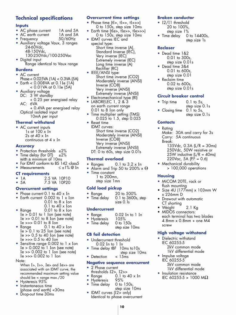
Technical specificationsInputs• AC phase current 1A and 5A• AC earth current 1A and 5A• Frequency 50/60Hz• Auxiliary voltage Vaux, 3 ranges
24-60Vdc, 48-150Vdc, 130-250Vdc/100-250Vac
• Digital inputRange identical to Vaux range
Burdens• AC current
Phase< 0.025VA (1A) < 0.3VA (5A)• Earth < 0.008VA at 0.1Ie (1A)
< 0.01VA at 0.1Ie (5A)• Auxiliary voltage
DC: 3 W standby + 0.25 per energised relay
AC: 6VA + 0.4VA per energised relay
Optical isolated input10mA per input
Thermal withstand• AC current inputs
1s at 100 x In2s at 40 x Incontinuous at 4 x In
Accuracy• Protection thresholds ±2%• Time delay (for DT) ±2%
with a minimum of 10ms• For IDMT conform to BS 142 -class5• Measurements ≤ ±1% @ InCT requirements • 1A 2.5 VA 10P10• 5A 7.5 VA 10P20 Overcurrent settings• Phase current 0.1 to 40 x In• Earth current 0.002 to 1 x Ion
0.01 to 8 x Ion0.1 to 40 x Ion
• Range 0.01 to 8 x IonIe > 0.01 to 1 Ion (see note)Ie >> 0.01 to 8 Ion (see note)Ie >>> 0.01 to 8 Ion
• Range 0.1 to 40 x IonIe > 0.1 to 25 Ion (see note)Ie >> 0.5 to 40 Ion (see note)Ie >>> 0.5 to 40 Ion
• Sensitive range 0.002 to 1 x IonIe > 0.002 to 1 Ion (see note)Ie >> 0.002 to 1 Ion (see note)Ie >>> 0.002 to 1 Ion
Note: When I>, I>>, Ie> and Ie>> areassociated with an IDMT curve, therecommended maximum setting valueshould be < range max./20
• Hysteresis 95% • Instantaneous time
(phase and earth) <30ms• Drop-out time 30ms
Overcurrent time settings• Phase time (tI>, tI>>, tI>>>)
0 to 150s, step size 10ms• Earth time (tIe>, tIe>>, tIe>>>)
0 to 150s, step size 10ms• IDMT curves IEC and
special type: Short time inverse (A),Standard Inverse (IEC),Very inverse (IEC)Extremely inverse (IEC)Long time inverse (A)Rectifier (RC)
• IEEE/ANSI type: Short time inverse (CO2)Moderately inverse (ANSI)Inverse (CO8)Very inverse (ANSI)Extremely inverse (ANSI)
• Electromechanical type (RI)• LABORELEC 1, 2 & 3
on earth current range 0.01 to 8 Ion only
• Time multiplier setting (TMS)0.025 to 1.5, step 0.025
• Reset time IDMT curves:
Short time inverse (CO2)Moderately inverse (ANSI)Inverse (CO8)Very inverse (ANSI)Extremely inverse (ANSI)
DT: 0 to 60s, step size 0.01s
Thermal overload• Ranges 0.1 to 3.2 x In• Alarm and Trip 50 to 200% x Θ• Time constant
1 to 200mn, step size 1mn
Cold load pickup• Range 20 to 500%• Time delay 0.1 to 3600s, step
size 0.1s
Undercurrent• Range 0.02 In to 1 In• Hysteresis 105% • Time delay 0 to 150s
step size 10ms
CB fail detection• Undercurrent threshold
0.02 In to 1 In• Time delay tBF 10ms to10s
step size 10ms• Detection < 15msNegative sequence overcurrent• 2 Phase current
thresholds I2>, I2>>• Range 0.1 to 40 x In• Hysteresis 95% • Time delay 0 to 150s,
step size 10ms• IDMT curves (I2> only)
Identical to phase overcurrent
Broken conductor• I2/I1 threshold
20 to 100%, step size 1%
• Time delay 0 to 14400s, step size 1s
Recloser• Dead time 1&2
0.01 to 300s, step size 0.01s
• Dead time 3&40.01 to 600s, step size 0.01
• Reclaim time0.02 to 600s, step size 0.01s
Circuit breaker control• Trip time 0.1 to 5s,
step size 0.1s• Closing time 0.1 to 5s,
step size 0.1s
Contacts• Rating
Make: 30A and carry for 3sCarry: 5A continuousBreak:
135Vdc, 0.3A (L/R = 30ms)250Vdc, 50W resistive or 25W inductive (L/R = 40ms)220Vac, 5A (P.F = 0.6)
• Mechanical durability> 100,000 operations
Housing• MiCOM 20TE, rack or
flush mounting• Size 4U (177mm) x 103mm W
x 226mm D • Drawout with automatic
CT shorting• Weight 2.1 Kg• MIDOS connectors:
each terminal has two blades 4.8mm x 0.8mm + one M4screw
High voltage withstand• Dielectric withstand
IEC 60255-52kV common mode1kV differential mode
• Impulse voltageIEC 60255-5
5kV common mode1kV differential mode
• Insulation resistanceIEC 60255-5 > 1000 MΩ

11
ABC
AFMTUH
1234
012345678ABC
P 1 2 0MiCOMP 1 2 1MiCOMP 1 2 2MiCOMP 1 2 3MiCOM
0 01
MiCOMEarth current input
Auxiliary supply voltage Digital inputs voltage
0.1-40 Ion0.01-8 Ion0.002-1 Ion
Communication protocol
HMI languages
24-60 Vdc48-150 Vdc130-250 Vdc/100-250 Vac48-150 Vdc130-250 Vdc125-250 Vdc/100-250 Vac
24-60 Vdc48-150 Vdc130-250 Vdc/100-250 Vac48-150 Vdc (special EA)130-250 Vdc (special EA)95-150 Vdc (special application)
FrenchEnglish/AmericanSpanishGermanItalianRussianPolishPortugueseDutchCzechHungarianGreek
MOBDUSK-BUS/CourrierCEI 60870-5-103DNP3
Electrical environment• High frequency disturbance
IEC 61000-4-122.5kV common mode, class 31kV differential mode, class 3
• Fast transient disturbanceIEC 61000-4-4
4kV auxiliary voltage, class 4ANSI C37.90.1
2kV others, class 4• Electrostatic discharge
IEC 61000-4-28kV, class 4
• Radio Frequency Impulse
ANSI C37.90.2 35V/mIEC 61000-4-3 10V/m
Atmospheric environment• Temperature IEC 60255-6
Storage –25°C to +70°COperation –25°C to + 55°C
• Humidity IEC 60068-2-356 days at 93% RH and 40°C
• Enclosure protectionIEC 60529IP 52, IK 07
• VibrationsIEC 60255-21-1Response and endurance, class 2
• Shock IEC 60255-21-2,Response and withstand, class 1 & 2
• SeismicIEC 60255-21-3, class 2
• BumpIEC 60255-21-2, Response and withstand, class 1
Outline descriptionPhase and earth numericalovercurrent relay in drawout 4Umetal case.
The following functions areavailable:• 3 independent phase stages
(instantaneous and tine-delayed)50/51
• 3 independent earth stages(instantaneous and time-delayed)50N/51N
• Tripping curves type IEC (shorttime inverse, standard inverse,very inverse, extremely inverse,long time inverse) and IEEE/ANSI(short time inverse, moderatelyinverse, inverse, very inverse,extremely inverse)
• LABORELEC curves • Rectifier curve• Negative sequence
overcurrent - 46
Information required with order
• Undercurrent - 37• Thermal overload - 49• Output relay latching - 86• Broken conductor detection• 4 shot autorecloser - 79• Circuit breaker failure
detection - 50 BF• Circuit breaker monitoring• Trip circuit supervision
The relay provides completemeasurements and recordingfunctions including:• True RMS values• Event recorder with the last
75 events, 1ms time-tagged.• Fault recorder with the last 5 faults• Instantaneous recorder with the
last 5 instantaneous• Disturbance recorder with storage
of 5 records for 3 seconds each
User interface includes: • A 32-character backlit display• Programmable LEDs • A front panel EIA RS232 for local
settings• A EIA RS485 rear port
compatible with MODBUS,Courier, IEC 60870-5-103, or DNP3
• An easy to use PC setting software

Public
ation:
P12x
/EN
BR/L
m
© 2
003
ALS
TOM
-
0503
00 -
El
ectro
nic
file
- Mar
com
Transmission & Distribution Energy Automation & Information, Le Sextant, 3 avenue André Malraux, 92300 Levallois-Perret. FranceTel: +33 (0) 1 41 49 20 00 Fax: +33 (0) 1 41 49 24 85 [email protected] www.tde.alstom.com
Contact Centre on line 24 hours a day : +44 (0) 1785 25 00 70
ALSTOM, the ALSTOM logo and any alternative version thereof are trademarks and service marks of ALSTOM.MiCOM is a registered trademark of ALSTOM. Other names mentioned, registered or not, are the property of their respective companies.
Our policy is one of continuous development. Accordingly the design of our products may change at any time. Whilst every effort is made to produce up to date literature, thisbrochure should only be regarded as a guide and is intended for information purposes only. Its contents do not constitute an offer for sale or advice on the application of any product
referred to in it. We cannot be held responsible for any reliance on any decisions taken on its contents without specific advice.