P-TRE PULTRUDED PROFILE€¦ · The G.F.R.P. profiles are category E23 (UNI EN 13706-3:2003). LOAD...
19
www.fibrenet.it P-TREX PULTRUDED PROFILE PEDESTRIAN WALKWAY OVER THE ALENTA RIVER (Benevento, Italy) The restoration work on a reinforced concrete bridge over the Alenta river in the town of Ponte in the Italian province of Benevento, which had been damaged by the exceptional rainfalls in October 2015, presented the opportunity to create an adjacent pedestrian walkway in composite material, to house a series of underlying facilities. The flooding, caused by the exceptional rainfall, had damaged the bridge and the infrastructure attached to it, and forced the local council to call for emergency work to be carried out. In addition to repairing the vehicle bridge, it was decided to create a structure, during renovation of the damaged infrastructure, in G.F.R.P. pultruded profiles (Glass Fiber Reinforced Polymers), laid out in parallel to the span of the bridge. The aim was to house the underlying facilities (aqueduct, gas and sewer pipes) and allow them to be safely accessed for maintenance work. Pultruded material was chosen because of its light weight and decrease in the load bearing on the structure. It is also highly resistant to corrosion, adverse weather conditions and UV rays which makes it more durable and effective in the long term. The walkway structure, a double truss in GFRP pultruded profiles (Glass Fiber Reinforced Polymer) was designed in partnership with Fibre Net. The components were manufactured in the production department and fully assembled at the company site for testing. After testing was completed in partnership with the Department of Engineering and Architecture of the University of Trieste, the truss structure was dismantled into three parts and transported to the site for final assembly and installation. WORK SITE DIAGRAM SUBJECT: CLIENT: PROJECT MANAGER: DESIGNER: STRUCTURAL: IMPLEMENTATION GFRP WALKWAY: TIME FRAME: Repair of the bridge on the Alenta river Comune di Ponte (Benevento) Giovanna Colangelo (engineer) Annamaria Zotti (engineer) DESIGN SUPPORT Allen Dudine, Fibre Net S.r.l. Fibre Net S.r.l. Udine, Italy 2017-2018 The walkway in question with indications of its placement next to the existing bridge.
Transcript of P-TRE PULTRUDED PROFILE€¦ · The G.F.R.P. profiles are category E23 (UNI EN 13706-3:2003). LOAD...

www.fibrenet.it
P-TREX PULTRUDED PROFILE
PEDESTRIAN WALKWAY OVER THE ALENTA RIVER (Benevento, Italy) The restoration work on a reinforced concrete bridge over the Alenta river in the town of Ponte in the Italian province of Benevento, which had been damaged by the exceptional rainfalls in October 2015, presented the opportunity to create an adjacent pedestrian walkway in composite material, to house a series of underlying facilities.The flooding, caused by the exceptional rainfall, had damaged the bridge and the infrastructure attached to it, and forced the local council to call for emergency work to be carried out.In addition to repairing the vehicle bridge, it was decided to create a structure, during renovation of the damaged infrastructure, in G.F.R.P. pultruded profiles (Glass Fiber Reinforced Polymers), laid out in parallel to the span of the bridge. The aim was to house the underlying facilities (aqueduct, gas and sewer pipes) and allow them to be safely accessed for maintenance work.Pultruded material was chosen because of its light weight and decrease in the load bearing on the structure. It is also highly resistant to corrosion, adverse weather conditions and UV rays which makes it more durable and effective in the long term.The walkway structure, a double truss in GFRP pultruded profiles (Glass Fiber Reinforced Polymer) was designed in partnership with Fibre Net. The components were manufactured in the production department and fully assembled at the company site for testing. After testing was completed in partnership with the Department of Engineering and Architecture of the University of Trieste, the truss structure was dismantled into three parts and transported to the site for final assembly and installation.
WORK SITE DIAGRAM
SUBJECT :CLIENT:PROJECT MANAGER:DESIGNER:STRUCTURAL:IMPLEMENTATION GFRP WALKWAY:TIME FRAME:
Repair of the bridge on the Alenta riverComune di Ponte (Benevento)Giovanna Colangelo (engineer)Annamaria Zotti (engineer)DESIGN SUPPORT Allen Dudine, Fibre Net S.r.l.Fibre Net S.r.l. Udine, Italy2017-2018
The walkway in question with indications of its placement next to the existing bridge.

www.fibrenet.it
PROFILI PULTRUSI IN GFRPP-TREX PULTRUDED PROFILE
PROJECTThe need for a lightweight, durable structure led to the decision by the designers to use GFRP pultruded material, i.e. produced with continuous glass fibres and resin through an industrial process. This would result in one-dimensional elements shaped like those of traditional composite structures, but much lighter than steel components and more weather and corrosion-resistant. The significant decrease in the loads on the abutments compared to a metal structure simplified the design and facilitated the handling and installation of the structure using less powerful and, therefore, more compact lifting equipment. This was an important prerogative given the limited operating space in the work site.Lastly, the profile joints were sized using plates and bolted connections in steel since there was no requirement for the structure to be amagnetic.
The structure was modelled in three-dimensions, using both one-dimensional beam elements to model the trusses, and two-dimensional shell elements to model the grating.
The walkway grating was modelled as a shell element to distribute the horizontal and gravitational loads on the structural elements making up the framework of the trusses. The horizontal and vertical pultruded elements were inserted as one-dimensional beam elements.The value of the structural mass to calculate the vibration spaces of the structure was introduced based on the mass of the main structural elements, automatically calculated by the program and the permanent bearing loads and a quota of accidental loads.It was decided not to introduce any diaphragm plane constraints which would have linked the horizontal movements to the joints resting on the same plane.A rigid section was added to the supports to simulate the presence of the steel base plate and to allow rotation both in the design and testing phase. The continuity of the tie-rods was maintained where present through the joint as foreseen by the project specification.
Project numeric model, details of supports

www.fibrenet.it
P-TREX PULTRUDED PROFILE
Extruded numeric test model (1) Extruded numeric test model (2)
Extruded numeric test model (3)

www.fibrenet.it
PROFILI PULTRUSI IN GFRPP-TREX PULTRUDED PROFILE
In terms of the design of the structural elements, the loads were defined to obtain separate stresses (axial action, shear and bending moment) on the truss profiles and thus, determine the load capacity and the stresses reaching the foundation piles. This was executed before the handling and installation phase of the trusses and timed to allow consolidation and settling of the foundation blocks before completing the work.
The loads bearing on the main structures were introduced based on the placement of the structure in accordance with the criteria laid down by Italian Technical Regulations for Building 2008 and subsequent amendments in the Italian Ministerial Circular No 617/2009.Finally, during the design phase, the definition of the profiles required to create the supporting structure was carried out using the sizing and verification formulas in accordance with the Italian National Research Council guideline CNR DT 205/2007 “Instructions for the Design, Execution and Control of Structures made with Pultruded Profiles of Fiber-Reinforced Composite Material (FRP)” using a simplified numerical analysis, as is the case for the design of standard composite structures.
Diagram of axial forces due to combined loads

www.fibrenet.it
P-TREX PULTRUDED PROFILE
STRUCTUREThe walkway consists of a single-span truss structure, with a 28700 mm span. In particular, it consists of two adjacent (Warren type) trusses, 1600-mm in height, placed at a distance of 1000 mm and joined together by cross-beams and diagonal tie-rods.The truss is created by assembling G.F.R.P. composite pultruded profiles, connected by steel bolts and plates. There are metal anchoring plates at the base of the end uprights which were attached, on site, to the reinforced concrete foundation blocks by means of steel anchor boltsThe elements making up the upper and lower beams and the end uprights are obtained by joining pairs of C300 pultruded profiles while two C200 pultruded profiles were used for the diagonals. The diagonals were placed at 38° compared to the horizontal beam. Intermediate uprights (two per side), made from 10-mm thick metal tubes with a diameter of 168.3 mm, are also used to make a torsionally rigid structure and facilitate installation. This guarantees a sufficiently rigid section for handling (the structure was designed with the aim of defining the load combination for lifting as well).The bracing system consists of horizontal X-shaped and vertical V-shaped metal tie rods. IPE150 pultruded elements were installed on the upper beam, creating a secondary framework, aimed at supporting the G.F.R.P. walkway grating once installed (not installed in the testing phase and added at the work site).
Detail of the walkway: perspective, view from above and below

www.fibrenet.it
PROFILI PULTRUSI IN GFRPP-TREX PULTRUDED PROFILE
MATERIALSStructures in fibre-reinforced composite material > GFRP pultruded profilesStandard concrete class C28/35 > Reinforced concrete for foundation blocksS275JR grade steel structures > Connection plates and railingsB450C steel bars and mesh > Reinforcement for foundation blocksClass 8.8 bolts > Bolts for joints between pultruded profiles
All the metal elements are made of S275JR grade steel (UNI EN 10027-1:2016) and the joints use M16 Class 8.8 bolts (UNI EN 14399-4:2015). The G.F.R.P. profiles are category E23 (UNI EN 13706-3:2003).
LOAD TESTINGThe walkway in pultruded profiles was fully assembled at the company’s production site and subjected to load testing to assess the deformation capacity to vertical loads.As foreseen for the actual installation, for the load testing, the walkway was installed after assembly on the ground of three different truss sections, two end sections and one central section. The three elements were positioned in the required configuration using lifting and handling machines and joined together at the height of the upper and lower beams using bolted joints fitted with metal plates on the inside and plate covers on the outside in pultruded material. After assembly, the bolted joints were tightened and the wind bracing tie-rods were installed and tensioned.
Detail of the walkway: section

www.fibrenet.it
P-TREX PULTRUDED PROFILE
The walkway assembled for load testing Detail of the interlocking elements and joints
PREPARATION AND ASSEMBLY

www.fibrenet.it
PROFILI PULTRUSI IN GFRPP-TREX PULTRUDED PROFILE
There are metal anchor plates at the base of the end uprights which were secured, in the installation phase, to the foundation blocks prepared on site by means of anchor bolts.Under test conditions, each of the two walkway support bases was installed by placing two concrete blocks (1000x1000x1000 mm3) side by side on the concrete base of the testing laboratory. A base block in cementitious mortar was then made (30-40 mm thick) to even out the support surface and ensure that it was level. A metal plate was then bonded to the base block using epoxy resin. Two steel cylinders were positioned on this and the walkway placed on top via the metal base plates.
During the testing phase, the walkway was subjected to vertical loads on several nodes of the upper beams of the truss. Two different tests were carried out in particular, according to two different load patterns.

www.fibrenet.it
P-TREX PULTRUDED PROFILE
TEST 1 > application of a series of concentrated loads of the same size on the four central nodes of each of the upper two beams.
www.fibrenet.it
PROFILI PULTRUSI IN GFRPP-TREX PULTRUDED PROFILE
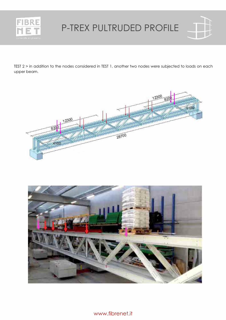
TEST 2 > in addition to the nodes considered in TEST 1, another two nodes were subjected to loads on each upper beam.

www.fibrenet.it
P-TREX PULTRUDED PROFILE
Two double-acting hydraulic cylinders (Hydrafore YG-20300S, 20 tonnes, 300 mm stroke), connected together, were used to apply the load on the four central nodes of each of the upper two beams. For the additional loads introduced in TEST 2, ballast was used (pallets stacked with sacks of mortar).
Detailed illustration of the load application system

www.fibrenet.it
PROFILI PULTRUSI IN GFRPP-TREX PULTRUDED PROFILE
The test set-up included the installation of fourteen displacement transducers and two pressure transducers connected to two Dewe-43 electronic data acquisition systems (8-channel control box), linked to a computer. It was, therefore, possible to monitor the trend over time and based on the load deformation curve of the walkway.
Deformations on the structure, highlighting the maximum bending for the combination of test loads
The results of the two load tests are summarised in the two graphs which show the trend in movement (downward movements, for the sake of simplicity, with a positive sign) based on the total vertical load applied by the cylinders (also with a positive sign).

www.fibrenet.it
P-TREX PULTRUDED PROFILE
TEST 1: Average displacement (ballast + cylinders) based on load applied by the cylinders alone.
TEST 2: Average displacement (ballast + cylinders) based on load applied by the cylinders alone.
Load
[kN
]
Displacements [mm]
Displacements [mm]
Load
[kN
]

www.fibrenet.it
PROFILI PULTRUSI IN GFRPP-TREX PULTRUDED PROFILE
The results obtained from the two experiments showed that the numerical modelling was accurate in predicting the performance of the structure. It also highlighted that the design of the nodes and the joining of the three walkway sections was effective, given that the structure performed in a similar way to a one-dimensional element subject to bending and the hole/bolt tolerances (quantified as residual deformation of structure subsidence) were minimal.
TRANSPORT AND ASSEMBLY ON SITEAfter completing the load tests, the structure was dismantled into three parts for transportation to the site and subsequent assembly.The three separate pieces - called LH, central and RH - were assembled on site directly on the existing reinforced concrete vehicle bridge as indicated in the “Guidelines for the assembly of the structural part of the project” drafted during the design phase.After assembly of the three parts was completed, the composite laminate plates were laid out to join the pultruded profiles, with continuity in terms of mechanical strength, bonded with specific resin. Once the resin had cured and bonded after about 24 hours, the profiles were bolted to the central support of the walkway grating and the two remaining pairs of tie-rods were put in place.
The lifting and installation phase of the structure was carried out using ropes and belts positioned according to the project diagram and with careful handling to avoid abrupt movements of the lifting apparatus.Following installation, checks were carried out to ensure that the structural elements were suitable and the steel tie-rods had been properly tensioned. The nuts of the anchor bolts, which had previously been inserted in the reinforced concrete foundation blocks of the structure using specific templates, were then fastened and closed with a torque wrench to secure the structure to the foundation.
Lastly, to complete the installation process, pipes were inserted under the walkway surface for the installation of the underlying facilities as per the project, and the walkway railings were added. The work was concluded with the installation of the walkway grating which was secured to the structure using appropriate fastening devices.

www.fibrenet.it
P-TREX PULTRUDED PROFILE

www.fibrenet.it
PROFILI PULTRUSI IN GFRPP-TREX PULTRUDED PROFILE
Assembly phases of the three parts of the walkway transported on site for assembly
Final assembly stages of the structure before installation

www.fibrenet.it
P-TREX PULTRUDED PROFILE
Lifting and installation on site

www.fibrenet.it
PROFILI PULTRUSI IN GFRPP-TREX PULTRUDED PROFILE
Securing the structure to the foundation blocks
Article by Engineer Allen DudineFiber Net technical office

www.fibrenet.it
P-TREX PULTRUDED PROFILE
Fibre Net S.r.l Via Jacopo Stellini, 3 - Z.I.U.
33050 Pavia di Udine (Ud) ITALY Tel. +39 0432 600918
www.fibrenet.it - [email protected]