P r o j e c t 4 - R e d F e a th e r T h e r m a l E n e r ...
54
Project 4 - Red Feather Thermal Energy for Homes Final Report Jeffrey Macauley Jake Shaw Edwin Beraud Will Legrand 2018-2019 Project Sponsor: Mark Hall Faculty Advisor: Dr. Carson Pete Instructor: Dr. David Willy 1
Transcript of P r o j e c t 4 - R e d F e a th e r T h e r m a l E n e r ...

Project 4 - Red Feather Thermal Energy for Homes
Final Report
Jeffrey Macauley Jake Shaw
Edwin Beraud Will Legrand
2018-2019
Project Sponsor: Mark Hall
Faculty Advisor: Dr. Carson Pete
Instructor: Dr. David Willy
1

DISCLAIMER This report was prepared by students as part of a university course requirement. While considerable effort has been put into the project, it is not the work of licensed engineers and has not undergone the extensive verification that is common in the profession. The information, data, conclusions, and content of this report should not be relied on or utilized without thorough, independent testing and verification. University faculty members may have been associated with this project as advisors, sponsors, or course instructors, but as such they are not responsible for the accuracy of results or conclusions.
2

EXECUTIVE SUMMARY Currently, a major health and energy crisis affects the Navajo and Hopi Native American reservations in Northern Arizona and New Mexico. The winter months bring cold temperatures to these regions, and to keep warm, residents often use coal and wood stoves. The pollution created by burning these fuels causes high rates of asthma and other respiratory diseases in inadequately ventilated homes. Additionally, the recent closure of the Kayenta Coal Mine, located on the reservation, prevents many residents from having ample access to coal, and wood resources are becoming strained as all coal-burning residents are forced to switch to wood. The lack of disposable income available to many residents in these regions further limits options for alternative heating methods.
The team’s goal for this project is to work with a Flagstaff non-profit organization, Red Feather Development Group, to provide an analysis of potential solutions to these issues. The team addressed a variety of potential options to eliminate or reduce the usage of fuel. One initial consideration was the usage of a solar furnace as a means of collecting the solar thermal energy available from the sun during the day. The lack of available energy at night necessitated the use of energy storage, in the form of Phase Change Material (PCM), as a means of continuing to use the energy provided during the day at night. Team members also considered structural modifications, such as insulation and double pane windows, as means of reducing the energy needed to heat the home, therefore reducing fuel consumption.
Upon extensive technical analysis and research covering a concept system with a PCM battery and solar furnace, team members concluded that the amount of PCM required to provide a noticeable impact was too large to be financially feasible for this project. Therefore, a PCM battery was deemed not viable in the context of this project. While solar thermal energy collection through a solar furnace has viable benefits even when used in conjunction with a fuel-burning stove without a PCM battery, these benefits are not substantial enough to justify the extensive cost of installation. Further analysis using energy storage calculations and the energy modeling software eQUEST, led team members to the conclusion that insulation is the most effective mean of reducing energy consumption for the type of home specified.
Moving forward with the analysis, the team seeks to further assess the effectiveness of various improvements in building construction. These include the most effective amount of insulation compared to the cost of the design, the point at which double pane windows become a reasonable investment, and other potential improvements to structures which would reduce fuel consumption without creating a prohibitively large overnight cost. Alternative heating sources such as a propane furnace are being researched as a means to cut back on the pollutants produced by a coal furnace as well. The team is also considering means to test these parameters using an actual physical model.
3

ACKNOWLEDGEMENTS After the extensive work completed this semester, Team 4 would like to give thanks to multiple individuals in the Engineering Department of NAU for their assistance and contributions to the success of this project. The first person to recognize is the team’s Capstone sponsor, David Willy, who provided feedback at every step of this project, always looking for ways to help the team improve. The second faculty member to commend is Dr. Carson Pete for his continued assistance and knowledge in heat transfer-related matters for the project. Finally, the last faculty member to acknowledge is Grey Fowles, who assisted the team significantly with the usage of eQUEST to help develop the home energy models for this project.
4

TABLE OF CONTENTS
Contents DISCLAIMER 2
EXECUTIVE SUMMARY 2
ACKNOWLEDGEMENTS 3
TABLE OF CONTENTS 4
BACKGROUND 9 Introduction 9 Project Description 9
REQUIREMENTS 10 Customer Requirements (CRs) 10
Cannot Pose a Safety Hazard 10 Must be an Improvement From Current Heating Solution 10 Keeps Home at a Comfortable Temperature in Winter 10 Must Account for Heat Loss from Home 10 Must be Reliable with Temperature and Weather Fluctuations 10
Engineering Requirements (ERs) 11 Amount of Product Pollutants Produced 11 Thermal Efficiency of Heat Source 11 Temperature Maintained Inside Home 11 Thermal Resistance of Structure 11 Lifespan 11 Cost of Materials and Installation 12
Testing Procedures (TPs) 12 House of Quality (HoQ) 12
DESIGN SPACE RESEARCH 13 Literature Review 13
Team Member 1 (Edwin Beraud) 13 “Thermal Energy Storage Using Phase Change Materials” [3] 13 “Fundamentals of heat and mass transfer” [4] 13 “Report: High-Temperature Phase Change Materials (PCM) Candidates for Thermal Energy Storage (TES) Applications” [5] 13 “Thermal Energy Storage with Phase Change Material” [6] 13 “Phase change materials for solar thermal energy storage in residential buildings in cold climate” [7] 13 “Cost Analysis of Simple Phase Change Material-Enhanced Building Envelopes” [8] 14
5
“Insulation R-13 Vs. R-19” [9] 14 "Which Loose Fill Insulation is Best, Cellulose or Fiberglass?" [10] 14 "Recommended Home Insulation R– Values | ENERGY STAR" [11] 14 "Blown-In Insulation for Attics, Sidewalls, 19 lb. Bag | Greenfiber" [12] 14 “Insulating a Flat Roof” [13] 14 “2019 Average Blown-in Insulation Cost (with Price Factors)” [14] 14 "Attic Insulation | How Much Do I Need?" [15] 15 "What You Should Know About Blow-In Cellulose Insulation" [16] 15
Team Member 2 (Legrand William) 15 “Navajo Home Heating Practices, Their Impacts on Air Quality and Human Health, and a Framework to Identify Sustainable Solutions” [17] 15 “NAAQS Table” [1] 15 “Home Insulation Types: Advantages and Disadvantages” [18] 15 “Alternative Energy Systems and Applications” [19] 15 “Solar Energy: Fundamentals, Technology, and Systems” [20] 16
Team Member 3 (Jeff Macauley) 16 “Renewable energy technologies for sustainable development of energy efficient building” [21] 16 “Thermal analysis of a natural circulation solar air heater with phase change material energy storage” [22] 16 “Impact factors analysis on the thermal performance of hollow block wall” [23] 16 “Solar Energy Applications in Houses” [24] 16 “Types of Insulation" [25] 16 “Are space heaters more efficient than central heating" [26] 16 “Active solar heating" [27] 16
Team Member 4 (Jake Shaw) 17 “PreHeat: controlling home heating using occupancy prediction” [28] 17 "Cost-effective methods to improve the power output of a solar panel: An experimental investigation” [29] 17 “Radiant Heating” [30] 17 “Fundamentals of engineering thermodynamics” [31] 17 “Audel HVAC fundamentals” [32] 17 “Solar Heating and Cooling Technologies” [33] 18
Benchmarking 18 System Level Benchmarking 18
Existing Design #1: Solar Thermix Solar Air Heating System 18 Subsystem Level Benchmarking 20
Subsystem #1: Heat Source 20 Existing Design #1: Coal Furnace 21 Existing Design #2: Wood Stove 21
6

Existing Design #3: Propane Furnace 22 Existing Design #4: Solar Air Heaters 23
Subsystem #2: Air Circulation within Solar Furnace 24 Existing Design #1: Free Convection 24 Existing Design #2: Forced Convection 24
Functional Decomposition 25 Black Box Model 25 Functional Model/Work-Process Diagram/Hierarchical Task Analysis 25
CONCEPT GENERATION 27 Full System Concepts 27
Full System Design #1: Add Insulation, Leave Existing Furnace 27 Full System Design #2: Solar Furnace with Propane Space Heater 27 Full System Design #3: Solar Furnace With PCM and PV Panels 27 Full System Design #4: Solar Furnace With PV Panels and PCM Battery 28
Subsystem Concepts 29 Subsystem #1: Insulation [25] 29
Rolls and Loose Fills 29 Foam 29 Reflective Systems 30
Subsystem #2: Phase Change Materials 30 Design Option #1: Inorganic PCMs 30 Design Option #2: Organic PCMs 30 Design Option 3: Encapsulated PCMs 30
Subsystem #3: Solar Furnace Circulation Systems 31 Design #1: Turbine Fan 31 Design #2: Free Convection 31 Design #3: In-Wall Radiant Heating 31
CONCEPT SELECTION - FIRST SEMESTER 32 Technical Selection Criteria 32 Rationale for Design Selection 33 Analytical Summaries 34
Thermal Battery Geometry: Will Legrand 34 Effects of Mass Flow Rate on Heat Transfer: Jeff Macauley 34 PCM Analysis and Integration in eQUEST : Edwin Beraud 35 Solar Furnace Selection Process: Jake Shaw 37
Design Description 37 Qualitative Design Description 37 CAD Models 38
7

Bill of Materials (BOM) 38 eQUEST Models 39
ACCURATE MODELING IMPLEMENTATION PLAN 42
REFERENCES 43
APPENDICES 47 Appendix A: Calculations for PCM 47 Appendix B: eQUEST Calculations 48 Appendix C: Bill of Materials 49 Appendix D: CAD Models 50 Appendix E: House of Quality 53 Appendix F: Written Notes 54 Appendix G: Decision Matrix 54
8

1 BACKGROUND 1.1 Introduction This report addresses the current state of Team four’s Capstone Project at the end of the first semester, Spring 2019. This project fulfills the course requirement for ME476C, Mechanical Engineering Capstone I. The project is titled “Red Feather Thermal Energy for Homes,” and it was created by the client Mark Hall, the Executive Director of the Red Feather Development Group. The goal of the project is to provide efficient and low-cost heating solutions for homes on the Navajo and Hopi reservations during the winter. It is meant to benefit Navajo and Hopi communities by substituting or significantly reducing the burning of fuel, to reduce air pollution inside and outside the homes. The project intends to maintain the overall health of reservation members who have been negatively affected by the use of coal. Completion of this project will introduce a safer and more efficient heating option for reservation communities. It also pushes the Red Feather Development Group closer to their goal of creating sustainable solutions to the housing needs of people living on the reservation. The project will address issues such as eco-friendly energy production and energy efficient heating systems. The main objective of this project is to implement a heating system that is an improvement from current options available to residents in terms of air quality, thermal efficiency, and cost.
1.2 Project Description The Red Feather Development Group, a non-profit organization based in Flagstaff, works with the Navajo and Hopi Tribes to develop and implement sustainable solutions to these communities’ housing needs. Currently, the majority of these tribes use coal or wood to heat their homes during the cold winters due to their lack of access to electricity and natural gas. Wood and coal smoke is one of the leading contributors to the higher respiratory disease rates on American Indian Reservation. With the closure of the coal-fired electric plant and the mine that supplies it, coal is expected to become very scarce over the next couple years for the reservation. It is expected that the majority of households using primarily coal to heat their homes will switch to wood, since it can be burned in the same stove, and historically has been reasonably abundant. Unfortunately, tribal officials expect that this increase in the demand for wood will strain local woodlands and rapidly create a similar scarcity for both fuels. This capstone project tasks a team of four students to research and develop sustainable and lasting solutions to the heating issue being faced by the reservations. Factors such as yearly climate and weather patterns, methods of insulation, costs of heating systems and fuel types, and available resources will be analyzed to determine a final solution for the client. Solar thermal air heating systems and Phase Change Material thermal energy storage will be considered primarily per client’s request; however, all possible solutions will be analyzed for viability and cost-effectiveness. This project will begin as an analytical project where the team's final deliverables are in-depth theoretical models of the proposed solutions thoroughly backed by analyses and research. While not currently guaranteed, potential to procure extra sponsorship to provide resources for prototyping and testing may become available.
9

2 REQUIREMENTS The team compiled customer requirements after meeting with Mark Hall. Customer requirements were constructed from project deliverables and goals mentioned during team meetings with the client. Team members then produced engineering requirements to quantitatively evaluate the customer needs.
2.1 Customer Requirements (CRs) The five customer requirements below encompass the most important needs of the team’s client. Each requirement was selected due to its importance in fulfilling the final goals and constraints for the design. The team relies on customer requirements to ensure the final design is satisfactory to the client. 2.1.1 Cannot Pose a Safety Hazard The system must not pose a safety hazard to the occupants of the home or surrounding area. A current problem with home heating systems on the reservation is the toxicity of pollutants from burning coal, wood, and trash being released into homes. Particulates created by wood and coal stoves have the potential to vent back into the home, causing residents to breathe in the smoke and experience health problems. In the context of this project, it is also important to account for the effect on surrounding air quality in the community, as even adequately ventilated systems can cause health problems if they are concentrated in a single area. 2.1.2 Must be an Improvement From Current Heating Solution The design the team creates must be an improvement from the original design in terms of cost, air quality, and efficiency. To justify the expense and difficulty of a widespread overhaul of home heating systems across the reservation, the new system must provide enough of a benefit over the original that the results are substantial. 2.1.3 Keeps Home at a Comfortable Temperature in Winter The system must heat the home adequately enough to keep it at a comfortable temperature throughout the day during the cold winter months. Regardless of the weather or temperature conditions in the region, the system should be able to heat the home to a constant temperature. 2.1.4 Must Account for Heat Loss from Home A home loses heat through walls, windows, and doors when these features are poorly insulated. The final design must provide enough well-placed insulating features to reduce the heat loss through the home. Using these metrics, the final design must optimize heating power and insulation to minimize costs and energy usage. 2.1.5 Must be Reliable with Temperature and Weather Fluctuations The system should be able to function in variable temperatures caused by different weather conditions and seasons. The system should not experience damage or wear under conditions of extreme temperature and should continue to heat the home under these conditions. It must have a backup system or redundancy if its operation is dependent on certain conditions or times of day.
10

2.2 Engineering Requirements (ERs) The engineering requirements are quantifiable parameters that can be measured and tested on the final design. They allow the team to relate the qualitative information from the customer requirements to the quantitative measurements from the design. The values of these parameters help determine the degree to which the design achieves the customer needs. 2.2.1 Amount of Product Pollutants Produced The EPA and other organizations assess the relative ‘cleanness’ of a type of fuel by determining the number potentially hazardous particles contained in the smoke generated by burning a certain amount of fuel. This is an important factor as it can be used to gauge the health impact generated from burning different types of fuel. These types of particles include NO2, NO3, SO2, and SO3 when comparing results to an EPA generated standard. According to the EPA, the amount of product pollutants generated must be less than about 10 µg/m3 annually and 35 µg/m3 maximum within 24 hours as to not cause respiratory health risk [1]. 2.2.2 Thermal Efficiency of Heat Source The thermal efficiency of the system is the extent to which thermal energy is preserved throughout the system’s operation. A system with a low thermal efficiency will waste the energy resource, whether it is in the form of solar energy or chemical energy from a fuel. Based on the assumption that a wood or coal stove usually has an efficiency of around 70%, the heat source must have a thermal efficiency of 70% +/-10% [2]. 2.2.3 Temperature Maintained Inside Home An important parameter of the system is the temperature it is able to maintain inside the home. Regardless of conditions, the system must be able to maintain a temperature comfortable to residents to be an effective substitute for the current systems. Therefore, a target for the temperature to be maintained inside the home is 72 degrees Fahrenheit, +/- 3 degrees. 2.2.4 Thermal Resistance of Structure To analyze the heat the home loses to the outside air, one can treat the home as a thermal resistive network. Heat can escape through any parts of the home exposed to both the inside and outside of the structure, such as walls, doors, windows, and roofs. The equivalent thermal resistance can be calculated as one value that reflects the extent to which the structure as a whole resists the flow of heat in and out of the home. To keep a more stable temperature inside the home, the team should strive to create a design with as high of a resistance as possible. For a standard cinder block home, the thermal resistance is equal to R ~2.2 K/W+0.3 K/W, the team’s initial target value. 2.2.5 Lifespan To be financially viable, the system must be operational without replacement for a long enough time to recoup the initial investment of purchasing and installing the system. The life span encompasses the amount of time the system can function at its full potential without increased need for maintenance. The target lifespan for this system is 10 years, +/- 2 years, though this may vary depending on the up front cost of the system.
11
2.2.6 Cost of Materials and Installation The cost of materials and installation is the initial cost the residents or sponsors must pay to have the system installed in their home. This cost must be low enough such that reservation communities are able to afford it. It also must be justified by potential energy savings and cost reduction. The target cost for this design, specified by the client, is $1,200, +/- $300. 2.3 Testing Procedures (TPs) Testing procedure data for benchmarked designs, including solar furnaces and phase change materials, have been obtained from specification sheets provided by manufacturers. For budgeting reasons, the team chose to rely on this information rather than engage in original testing procedures. Factors taken into consideration during the manufacturers’ testing procedures included air quality, cost, thermal efficiency, heat output or heat retention per the design considered, and safety. More accurate results of these tests can be determined by using the specified technique in the allotted space of the house of quality diagram. Since the team does not have the physical budget to perform the necessary testing there is a moderate amount of uncertainty in these. 2.4 House of Quality (HoQ) The house of quality was used to break down the project description into specific customer needs and associated engineering requirements, and allow the team to evaluate the needs and constraints of the project into specific focus areas. The team’s house of quality can be found in Appendix A. The most important engineering requirements, as determined through correlations with weighted customer requirements, are thermal efficiency, cost, and thermal resistance value. Thermal efficiency relates to almost all customer needs and provides a basis for how effectively the system uses energy. Using this information, the team is able to identify the areas of the project which require the most attention. The house of quality also allows the team to outline the final design based on target values for the engineering requirements. For example, the thermal resistance value of the home must be above 2.2 which is the K
W resistance of cinder block used in many reservation homes. The team will continue to utilize the HoQ for the duration of the project to ensure that target values are met and customer needs are followed.
12

3 DESIGN SPACE RESEARCH To begin the development of a design concept, Team 4 researched a variety of articles, websites, and books, which are listed below. These sources all provided specific information crucial to the project development and understanding of the systems involved in it. Additionally, benchmarks to compare the usefulness of the system are shown in these sources; hence this broadens the scope of the project by introducing varied systems that offer potential solutions through multiple approaches. 3.1 Literature Review This section presents the literary research conducted by each team member. Each team member’s research focused on a different aspect of the project. These sources will have a brief description of their contents followed after their citation. 3.1.1 Team Member 1 (Edwin Beraud) This team member’s main focus was researching Phase Change Materials to come up with a decision for a final PCM to use in the Capstone Project. This team member was also responsible for finding information on how to model PCM with software. Team members use energy modeling to analyze the extent to which PCM applications have an effect on the overall energy consumption . Additionally, the team member researched insulation types to use in models along with their prices. 3.1.1.1 “Thermal Energy Storage Using Phase Change Materials” [3] This book has in-depth data about Phase Change materials. It covers different uses of PCMs, their operation, and their incorporation into different applications ranging from electronics, constructions, etc. 3.1.1.2 “Fundamentals of heat and mass transfer” [4] This book contains data regarding heat transfer. It is useful to understand the theoretical functioning of Phase Change Materials. It also covers methods of heat transfer and specific terminology to the subject. 3.1.1.3 “Report: High-Temperature Phase Change Materials (PCM) Candidates for
Thermal Energy Storage (TES) Applications” [5] This article contains information on High-Temperature Phase change materials with corrosive properties. The article tests different kinds of PCMs and finds discrepancies between the data reported by the PCM manufacturer and experimental data. While the PCM used here are unlikely to be used due to their corrosive properties, they are not ruled out entirely in the design process since the temperature of operation for the final Capstone design might require them. 3.1.1.4 “Thermal Energy Storage with Phase Change Material” [6] This article provides insight into the different types of PCMs. It explains their differences and provides tables with properties of the materials. Additionally, this article does not only give properties but explains the pros and cons of every type of PCM. It will come handy in the PCM selection process. 3.1.1.5 “Phase change materials for solar thermal energy storage in residential
13
buildings in cold climate” [7] This article has a detailed explanation of an experiment conducted using PCM’s to heat residential buildings exposed to cold weathers in China. It contains plenty of information of the PCM selection criteria that was considered, as well as modeling data of the which can come handy to the projects as a way to approach the problem. 3.1.1.6 “Cost Analysis of Simple Phase Change Material-Enhanced Building Envelopes”
[8] This report provides data on modeling PCMs with DOE, Energy Plus. and also costs related to the improvements that can be achieved with these materials. The report also states the estimated costs PCMs should have to pay back their cost in benefit over the period of 10 years. Additionally, the article suggests improvements to reduce costs of PCMs while increasing their effectiveness. This document is useful to determine appropriate PCMs based on their costs. It will also give insight into how to simulate PCMs. 3.1.1.7 “Insulation R-13 Vs. R-19” [9] This article provides a comparison, done by the US Department of Energy between insulations R19 and R13. This was a useful information source since the team had to mainly consider advantages and affordability for these types of insulation. Thanks to this R13 was set as the insulation to use. 3.1.1.8 "Which Loose Fill Insulation is Best, Cellulose or Fiberglass?" [10] This source does a comparison between loose fill insulation vs loose fill fiberglass as insulation in homes and determines that fiberglass tends to prevail as the preferred insulation type due to its cheap cost; however cellulose benefits, while a bit more expensive, tend to be greater.
3.1.1.9 "Recommended Home Insulation R– Values | ENERGY STAR" [11] This source provides US weather zones and the best insulation types to use for each in uninsulated attics . While a brief informational source it helps determine the best insulations to use for the weather zone that is being considered for this project. 3.1.1.10 "Blown-In Insulation for Attics, Sidewalls, 19 lb. Bag | Greenfiber" [12] This source is specific to green fiber loose-fill insulation specification for cellulose Blow in insulation. It provides important values to use to insulate homes depending on the resistance value desired by installer. This source was very useful for calculation to determine the amounts of cellulose needed to insulate the home in an attic and walls. 3.1.1.11 “Insulating a Flat Roof” [13] This source provides helpful insight into how to insulate a flat roof specifically. It discussed the types of insulation needed to be used depending on the rafter size of the roofing and explains that regardless of size, loose-fill cellulose can be used in most cases described.
3.1.1.12 “2019 Average Blown-in Insulation Cost (with Price Factors)” [14] This source provided a very detailed comparison between cellulose insulation, fiberglass and rock wool. It goes in depth into its benefits and what Resistance value each provides on average. This is very helpful to determine the insulation types
14

3.1.1.13 "Attic Insulation | How Much Do I Need?" [15] This source provides the weather zones in the US and tables providing the best insulation types per region. This was helpful to set the insulation types that could be used in the eQUEST model. 3.1.1.14 "What You Should Know About Blow-In Cellulose Insulation" [16] This article provides insight into insulation applications for attics and walls. It also provides information about cellulose blow in insulation and compares it to fiberglass batt insulation. Overall, the article explains the pros and cons of each insulation type, along with the ease of installation for do-it-yourself installation. 3.1.2 Team Member 2 (Legrand William) This team member’s research focused on the air quality impacts of fuel burning, and potential renewable energy solutions that do not generate pollution. This research also evaluated the advantages and disadvantages of different types of insulation. 3.1.2.1 “Navajo Home Heating Practices, Their Impacts on Air Quality and Human
Health, and a Framework to Identify Sustainable Solutions” [17] This article focuses specifically on heating homes on the Navajo Nation reservation. It explains many of the problems of current heating practices in terms of pollution and demographic health and explains where experts currently stand in formulating solutions to this problem. 3.1.2.2 “NAAQS Table” [1] This table, provided by the EPA, provides government standards and limits for levels of air particulates. An excessive level of exposure to course or fine particulates over an amount of time can create an impact on human respiratory health. In this table, the EPA specifies the limits of different particles that have been calculated as the maximum amount a human can breathe over specified amounts of time without facing health risks. Using these limits, along with measurements of the particulate output of the fuel burned in the system, the team can formulate the impact the system will have on improving air quality and health standards if applied on the reservation. 3.1.2.3 “Home Insulation Types: Advantages and Disadvantages” [18] This webpage lists several types of insulation, along with their respective costs and R values. R values determine how much heat loss insulation will be prevented across walls. Using software and calculations, the team is able to determine how much of what type of insulation will provide the ideal improvements at the lowest cost. 3.1.2.4 “Alternative Energy Systems and Applications” [19] This textbook overviews renewable forms of energy, including solar and wind energy, along with how they can be applied to generate power. It also considers how existing forms of energy generation can be modified to increase their efficiency. It provides applications of energy that have the potential to be used on the Navajo Nation Reservation.
15

3.1.2.5 “Solar Energy: Fundamentals, Technology, and Systems” [20] This book focuses on solar energy specifically and includes sections on the types of Solar Thermal Energy the team is researching for potential use in the project. 3.1.3 Team Member 3 (Jeff Macauley)
3.1.3.1 “Renewable energy technologies for sustainable development of energy efficient
building” [21] Since this project lies within the realm of energy-efficient building techniques, this article is a great source of information. It contains various environmentally friendly methods of reducing a home’s energy requirements when it comes to heating and cooling, while also touching on the economics of such methods. 3.1.3.2 “Thermal analysis of a natural circulation solar air heater with phase change
material energy storage” [22] This article proves useful in that it provides insight into how a solar furnace operates with PCMs with data on its results. This is of particular interest to the client, as a means to determine ways to heat a home without producing extra pollution, health, and safety risks. 3.1.3.3 “Impact factors analysis on the thermal performance of hollow block wall” [23] This article is an important resource because it provides information on the thermal performance of a hollow block wall. Modeling a cinder block home for testing purposes and benchmarking is an important part within the scope of this project, as cinder block is the construction material specified by the client. 3.1.3.4 “Solar Energy Applications in Houses” [24] This is an old textbook that covers a wide range of important topics in regards to applications of solar energy in homes. This book gives information on space heating requirements and different uses of solar energy, as well as the performance and economics of these applications and much more. 3.1.3.5 “Types of Insulation" [25] This website contains information on the various forms of insulation, their applications and notes briefly on resistance values. It also makes comments on effectiveness in different climates and cost efficiency, whether insulating a home undergoing construction or working with an existing structure. 3.1.3.6 “Are space heaters more efficient than central heating" [26] This article considers two different forms of heating, including central heating and space heaters. Both of these systems are assumed to run off propane in the context of this article. This article describes which propane system would likely be the best option for several given situations. For example, if a small room is being heated, a space heater will work perfectly, while if heating a home, central heating or HVAC systems are always more efficient. 3.1.3.7 “Active solar heating" [27] This article published by the department of energy focuses on the difference between passive and active
16
solar air heaters. Active solar heaters have a forced air flow or a fan that is regulating the mass flow through the heater. Passive heaters let natural convective currents circulate air into the home. The article also describes the benefits and negatives of air and water radiant heating systems. 3.1.4 Team Member 4 (Jake Shaw) 3.1.4.1 “PreHeat: controlling home heating using occupancy prediction” [28] This peer-reviewed article discusses a method for improving energy usage by using occupancy sensing and occupancy prediction when heating the home. Many homes have a scheduling feature on the thermostat but most Americans do not utilize this feature. The authors of this article experimented with this method in five different homes. Results found a 6x-12x reduction in miss time, which is defined as the time when the home is occupied but not warm. This article could be useful for the project because one of the main customer needs is regulating the home at a constant temperature to keep the occupants comfortable. This method could potentially be used to ensure that the temperature inside the home is comfortable and the system is energy efficient.
3.1.4.2 "Cost-effective methods to improve the power output of a solar panel: An
experimental investigation” [29] This peer-reviewed article discusses a method to improve the power generated by photovoltaic solar panels. The method uses a four-mirror system to direct sunlight onto the panel without any tracking of the sun. Experiments with this system showed a 30.54% increase in short-circuit current. Solar PV panels may be implemented into the final design of this project to power a small fan and a thermostat system. The team wants to ensure that the fan will always have a power supply or else, the home will not be heated with this system. The method described in this article is also very cheap because it only requires four mirrors directed at the correct angle.
3.1.4.3 “Radiant Heating” [30] This webpage was created by the department of energy. It discusses a method for heat dispersal involving panels placed in the walls, ceiling, or flooring of the homes. The panels are heated up by tubes which run along the surface. The tubes may carry either hot water or air. The advantage of using air as the working fluid is that it can be implemented with a solar air heating system. However, air does not retain heat as well as water. Using water as the working fluid is the most popular and cost-effective radiant heating system. Most reservation homes also have access to running water so the team would only need to implement some sort of boiler to heat the water. The main disadvantage of this method is that it has high installation costs due to the invasive procedure of removing the walls or flooring. The design may have potential as a type of heat dispersal method associated with the solar furnace.
3.1.4.4 “Fundamentals of engineering thermodynamics” [31] This book is used for many undergraduate thermodynamic classes. It covers a range of thermodynamic topics including efficiency, cycles, and heat transfer. The equations in this book may be useful to analyze a boiler or furnace in the home to find out heat transfer and work input. Multiple team members own the book so it will not be hard to acquire.
3.1.4.5 “Audel HVAC fundamentals” [32] This book covers the basics of HVAC systems. It discusses the best climates and households for certain
17
types of HVAC systems and explains how they work. The book will be useful if the team decides to implement an HVAC system in the future.
3.1.4.6 “Solar Heating and Cooling Technologies” [33] This government web page describes several types of solar thermal collectors. Each description covers how the collector works and the best climate/building for optimal performance. This source will certainly be helpful in the concept generation stage of the project when the team begins researching solar furnaces as an eco-friendly heat source. 3.2 Benchmarking Benchmarking data was acquired primarily by means of online research. This was done to establish a healthy base of information for proper evaluation of processes during functional decomposition, concept generation, technical selection and for other various uses throughout the project. 3.2.1 System Level Benchmarking In order to benchmark system level designs of heating devices, the team decided to evaluate potential heating sources related to the primary design objective. These include a combination of solar designs with plausible circulation systems. Data gathered here will be useful in the selection of a final design during and after concept generation phases. 3.2.1.1 Existing Design #1: Solar Thermix Solar Air Heating System Solar Thermix is a company that develops sustainable solutions to minimize the dependence of fossil fuels in society. It is the creator of the concept of solar air heating which heats air using the sun's radiation along with a fan which produces an air flow in the thermal system to cycle the air [34]. These solar thermal systems allow for the migration of 1000 square feet of carbon yearly and have an estimated ability to pay for themselves in operational cost reduction after 3 years [34]. The system relates to the capstone team’s design since the idea of solar air heating will be used to warm homes at the Navajo and Hopi reservations due to its affordability and environmentally friendly operation. 3.2.1.2 Existing Design #2: Solar Furnace EcoSolaris’ design on a solar furnace was used as a benchmark to rate the final design [35]. The solar furnace works by absorbing solar radiation throughout the day and warming the air within it. Once this air is warm enough to provide sufficient heat to the home, a fan will then circulate the warm air from the furnace into the home and draw the cooler air from the home into the furnace. This design is very similar to the designs presented in the concept generation section of this document.
18

Figure 1 - Solar Furnace [35]
3.2.1.3 Existing Design #3: Radiant Heating System The most popular form of the radiant heating system involves panels placed in the flooring or walls of homes [30]. The panels have tubing that runs along their surface. The tubes carry hot water which then radiates heat into the home. The water is heated using a boiler running off of electricity. This method is a highly efficient way to heat the home but it is expensive to install. This system is more efficient than coal burning and does not release any pollutants to the air which is a huge improvement from the current heating systems on the reservation. The main downside of this design is the cost and the fact that a solar panel will need to be installed to power the boiler.
19

Figure 2 - Radiant Heating System [36]
3.2.1.4 Existing Design #4: Common Furnaces Furnaces are a common method of heating homes throughout the world. Furnaces’ popularity is due to the fact that they are inexpensive to run and easy to use. Most furnaces are designed to work by combusting materials within itself and then radiating that heat outwards into its surroundings, which would be the home. This inherently poses a fire safety hazard, which can be avoided with proper care and maintenance. Due to the popularity of using combustables to heat a home, chimney fires are fairly common and can cause remarkable amounts of damage to a home. This form of heating method also poses an air quality risk. Without adequate air circulation throughout the home, it is easy for particulate matter in the air to reach hazardous conditions. While furnaces come with some attractive benefits such as cost and effectiveness, they also come with some potentially dangerous negative effects. This system does have some advantages but the potential risk to one’s health are moderate.
3.2.2 Subsystem Level Benchmarking To thoroughly understand the benchmarked designs, the team has broken down system level benchmarks into smaller components or subsystems for further evaluation. This is important in understanding the complex functions of design and each components specific purpose in the final product. 3.2.2.1 Subsystem #1: Heat Source The following sections compare subsystems of common furnaces described previously in further detail. Furnaces are currently the main source of heat in many parts of the world, establishing a healthy base for benchmarking.
20

3.2.2.1.1 Existing Design #1: Coal Furnace
Coal furnaces are popular due to their ease of use and effectiveness. These work by burning coal loaded into the metal furnace to then radiate heat throughout the home. Once the coal fire has been started these take little upkeep for next to twelve hours. While the coal burns heat, smoke and ash are produced which is mostly directed up through the chimney. These systems are not completely sealed and can let some smoke and particulate matter into the home which can cause poor air quality conditions without proper ventilation. Regular maintenance is also required to reduce the risk of a chimney fire.
Figure 3 - Coal Stove [37]
3.2.2.1.2 Existing Design #2: Wood Stove
Wood stoves are popular in forested areas due to the availability of fuel. These work similar to a coal stove by burning wood loaded into the metal stove and radiating heat into the home and come with similar health and safety risks. These do take more effort to keep a consistent temperature than a coal stove because wood burns more quickly. Regulating these stoves can also be difficult without experience, it is easy to load to much fuel or too little which will make the home uncomfortably warm or put the fire out respectively.
21

Figure 4 - Wood Stove [38]
3.2.2.1.3 Existing Design #3: Propane Furnace
Propane provides a clean, efficient and sustainable method of heating. It also provides a number of different options depending on the capital investment with varying levels of effectiveness and operation cost. Indoor space heaters are relatively cheap, can be used to heat small rooms, and can be quite effective when used in that way. Though multiple space heaters used to heat an entire home is not as efficient as central heating systems. Central heating or HVAC systems are a far more efficient and effective way to heat an entire home using propane when compared to space heaters [26]. Yet to integrate a central heating system is far more expensive than a space heater unit or even several units. However, space heaters can pose a fire hazard if used improperly or left unattended and are responsible for roughly 25,000 home fires every year [26].
22

Figure 5 - Propane Furnace [39]
3.2.2.1.4 Existing Design #4: Solar Air Heaters
Solar air heaters are great methods for producing heat during the day though they function more as a supplemental heat source than as a primary. Solar air heaters obviously cannot produce heat when there is no solar resource, so this method will only reduce the energy load on a current systems primary method of heating. Once installed, there is little to no maintenance involved in operation and no fuel costs. Unfortunately solar air heaters are rather expensive to manufacture and install. Depending on the space heating requirements they can also become large, take up a lot of space and are not the most physically appealing.
23

Figure 6 - Solar Air Heater [40]
3.2.2.2 Subsystem #2: Air Circulation within Solar Furnace Generally solar air heaters are more or less made up of similar components. A glazed flat plate collector is made from copper tubing resting on an aluminum plate and iron tempered glass enclosing the collector. Ducting creating an inlet and outlet into the home and depending on the system it may have a integrated fan and differential temperature controlled to regulate convection or it may use natural convective currents to cycle air though the home.
3.2.2.2.1 Existing Design #1: Free Convection
Circulation inside of a solar furnace can be accomplished in two distinct ways. One of which is using natural convective currents produced by the heated air exchange inside of the solar furnace, known as passive solar heating [27]. This comes with some benefits and drawbacks to this design, using free convection means that additional power for circulation will not be required yet that also implies that the air flow through the heat exchanger is not regulated and therefore neither is temperature. Due to the lack of forced air it can be deduced that the this furnace will retain heat longer though not substantially.
3.2.2.2.2 Existing Design #2: Forced Convection
Integrating a fan into the ducting and a differential temperature controller to regulate temperature control allows for better heat exchange between the air heater and the home. This is known as an active system as it requires electricity to operate both the fan and the thermostat. Active solar heaters are most effective in cold climates with a large solar resource and are typically used to offset a primary method of heating such as coal or propane [27].
24

3.3 Functional Decomposition The black box model described below is an optimal and brief description of the system a system operating externally to collect air from the interior of the home and warm it up with an exterior source of heat. The functional model goes more in-depth into what this system will be using. The base of the project will be using a solar furnace to cycle cold air from within the home and warm it up by using fans to cycle this air and heat it up through the furnace. Moreover, an alternative generation of electric power will be desired as part of the project's goal to power the fans cycling the air in the system; hence photovoltaic (PV) panels are to be integrated in the design. What is being strived is to create a user-independent system so residents do not have to work to operate the system, as the home is automatically being heated over the winter. 3.3.1 Black Box Model The black box model for the design is shown below. It starts with the main functional process of the design, heating the home. Then, it determines the inputs and outputs, as materials, energy, and signals, that contribute to this purpose. This model assumes the system uses a solar furnace to collect solar thermal energy to directly heat the home, as this is the design the team is most likely to select. The black box model helps team members to define and break down the key inputs and outputs of the final design. It facilitates the development of a hypothetical or actual functional model by setting the parameters within which it must be built.
Figure 7 - Black Box Model
3.3.2 Functional Model/Work-Process Diagram/Hierarchical Task Analysis The functional model for heating the home can be found below. The functional model essentially breaks down the black box model into the specific sub-functions that lead to the outputs of the design. The team found it difficult to generalize the functional model because all the designs for heating a home are fairly unique. To make the process simpler, it was assumed that the team’s design would use a solar furnace to heat air which would be circulated around the house using a small fan during the day. At night, the coal furnace would be used for heating. The circulating fan can be automatically turned on during daylight hours with a scheduling feature while powered with the Photovoltaic(PV) panel. This will ensure that the fan is only using power when the solar furnace is generating heat. The furnace along with the PV panel are also assumed to be on the top of the home’s roof at 50.13 degrees for optimal performance based on the solar redbook data [41].
25

Figure 8 - Functional Decomposition Model
This functional decomposition has helped the team visualize the design’s essential functions needed to satisfy the project’s requirements for testing and analysis. Inspecting the figure reveals how the energy of the system is being used and converted. The diagram will be useful in the concept generation stage of the project because it will outline the exact sub-functions that need to be completed to achieve the desired outputs. It is important to note that the model here is still subject to change as the team researches and implements new ideas to meet customer requests.
26

4 CONCEPT GENERATION After extensive research and benchmarking of existing designs, team members entered the concept generation process. Based on research and brainstorming, the team defined three full system designs to research further. Each system can be comprised of different types of subsystems for which the team selected what they considered as the best designs. 4.1 Full System Concepts Three full system heating sources were conceived during concept generation. This includes various insulation types, a solar furnace with a propane space heater, and an integrated combination of a solar furnace with phase change materials. 4.1.1 Full System Design #1: Add Insulation, Leave Existing Furnace One design option for the structure is to leave the heating system intact as it is and focus on adding insulation to the house. This option has the potential benefits of low cost, low invasiveness of the installation, and no change to the resident who is assumed to have been using this system for an extended amount of time. However, this design also has many potential disadvantages. It continues to use coal and wood furnaces, which have substantial health risk, and these resources may become limited as the Kayenta Coal Mine closes. Insulating a home can be a tedious process that largely depends on the construction of the home and proper installation. The goal of insulating a home is to increase the overall thermal resistivity (R) of that space. There are many different forms of insulation including but not limited to: rolls or blankets, various foams, loose-fill, and even reflective systems [16]. If building a home, insulating concrete blocks or spray foams are good options to consider but if insulating an existing home loose fills and rolls are available. 4.1.2 Full System Design #2: Solar Furnace with Propane Space Heater Another full system design considered is to make use of a solar furnace during the day. This would take advantage of the free solar resource during the day and would help eliminate some fuel costs. Still a solar furnace will not produce enough heat to be a primary source of heating especially at night. For this purpose a supplemental heat source is needed in this case a propane space heater is considered. Space heaters are generally not designed to heat a whole home but a portion of it which makes this more efficient than a central heating system [26]. Yet does not meet the customer requirement of keeping the home a comfortable temperature, still this option is economically feasible and should therefore be considered. 4.1.3 Full System Design #3: Solar Furnace With PCM and PV Panels A solar furnace with phase change material (PCM) and photovoltaic (PV) panels shown in Figure 3, is a standalone heating system concept, generated by combining heat absorbers, PCMs and PV Panels. The PV panels along with the heat absorbers are lying in the surface of the furnace that receives sunlight. In this way, the PV panels generate power for a battery that supplies energy to a fan which takes in cold air from the environment to cycle inside the solar furnace. This air is then released back into the environment to heat up a home. This solution is intended to work with a thermostat to set up a temperature regulating system and will have PCMs integrated to retain heat collected by the absorbers inside the system. The
27

system’s PCMs are intended to have the heating system operate efficiently when the sun is not out.
Figure 9 - To the left, there is a side view of the Solar furnace with PCM and PV Integration, while a front view of the design is presented to the right
4.1.4 Full System Design #4: Solar Furnace With PV Panels and PCM Battery Just as in the previous design, this full system design has a solar furnace with a blackbody and PV panels integrated into the surface that gets radiation from the sun. A regular inlet and outlet are attached in the back of the panel for air to cycle inside the home, with the help of a fan operated with the PV energy. In addition to this, there is a second exit which leads hot air to a PCM battery for the sake of heat storage purposes. When the night comes, the user would just have to close off a valve from the exit pipe in order for the cold air to cycle through the PCM battery and collect heat that would then be used at the home. The schematic for this design is shown in Figure 4 below.
28

Figure 10 - To the left, there is a side view of the Solar furnace PV Integration, while a front view of the design is presented to the right. The system on the left has a regular inlet and outlet but has also a pipe attached to its bottom
which connects to a PCM battery for heat storage purposes.
4.2 Subsystem Concepts In order to provide the best design regarding heating sources, the team has broken down system level concepts into smaller components or subsystems for further evaluation. This is important for technical selection due to the similarities between designs but also to make sure that the appropriate design is selected for the task of heating a home. 4.2.1 Subsystem #1: Insulation [25] The following section compares various types of insulation, including prices and potential uses. 4.2.1.1 Rolls and Loose Fills Rolls and loose-fill insulation are used to fill walls and attics providing a thicker barrier to the outside and increasing thermal resistivity. Different materials are available such as fiberglass, plastic, cellulose and natural fibers like cotton or sheep's wool. Manufacturers are responsible for creating charts of resistance values with thickness for loose-fills since resistance does not change proportionally with thickness. These are relatively cheap and are easy enough for the homeowner to install without professional help. 4.2.1.2 Foam Foam can be used in several ways to insulate a home such as foam boards, liquid foam and spray foam. Foam boards can be used to line walls giving an added layer of resistance. Liquid foam can be sprayed or injected into hard to reach areas reducing air leaks. Certain foams called closed cell foams are used for hard to reach areas because it is filled with a gas that helps the foam to expand to fit an area.
29

4.2.1.3 Reflective Systems Reflective systems work by reflecting radiant heat. These are primarily installed in attics to reduce summer heat gain and lower cooling costs. Aluminum lined panels reduce radiant heat transfer from the underside of the roof to surfaces in the attic. These are most effective for warm climates and have little effect in cool climates. 4.2.2 Subsystem #2: Phase Change Materials Phase change materials (PCMs) are materials that undergo the solid-liquid phase transformation, at a temperature within the operating range of a selected thermal application [3]. As this material changes phase from a solid to a liquid state, it absorbs energy from its surroundings while remaining at a constant temperature [3]. At the melting temperature, the atomic bonds in the PCM loosen and the materials transitions from a solid to a liquid and in this process release the energy stored from its surroundings [3]. It is due to these properties that PCMs were being considered for integration in the heating system that is being designed in this project as a method to retain heat at homes without relying directly on electric power. Among the main PCM considerations are inorganic, organic and microencapsulated PCMs. 4.2.2.1 Design Option #1: Inorganic PCMs Inorganic PCMs have the benefits of high latent heat (heat that can be stored before temperature in PCM changes) and higher thermal conductivity [6]. These materials are not flammable and have lower cost in comparison to organic compounds, due to their high water content [6]. However, the downside to these PCMs is their corrosiveness, instability, and improper re-solidification [6]. On top of this, their properties can change due to decomposition or if the PCM is supercooled, but these two negative aspects can be avoided with nucleating agents applied to the PCMs [6]. 4.2.2.2 Design Option #2: Organic PCMs Organic PCMs made usually with paraffin, fatty acids, and sugar alcohols [8] which are more chemically stable than inorganic PCMs [6]. They are non-corrosive, have a high latent heat per unit weight, are recyclable, melt congruently, and have minimum susceptibility to supercooling [6]. Organic PCMs are suitable for heat absorption in building material [6]. Among their downsides are low thermal conductivity, high changes in volume during phase change, inflammability and they may generate harmful fumes on combustion [6]. Other problems that can arise from their use are reaction with the products of hydration in concrete, thermal oxidative aging, odor and an appreciable volume change [6]. 4.2.2.3 Design Option 3: Encapsulated PCMs The encapsulation of PCM material is done to increase the conductivity of PCMs in general. This can be a microencapsulation, where PCM of any state is stored within tiny particles with diameters smaller than 1 mm and larger than 1μm [6,42]. The microencapsulated PCM particles can then be incorporated in any matrix that is compatible with the encapsulating film, and this makes it so that low thermal conductivity is not a problem due to the ratio of surface area to volume being very high [6]. The main downside to microencapsulation is that capsules do not withstand very high temperatures[4]. The second type of containment is macro-encapsulation, which sets the PCMs in packaging in the forms of tubes, pouches, spheres, panels, etc [6]. These containers can serve directly as heat exchangers, but previous experiments with large volume containment have failed in the past due to poor conductivity of the PCM [6]. This occurred when the heat in the liquid phase was to be recovered since the PCM material
30

would solidify around the edges of its container, preventing heat transfer [6]. Based on these 3 types of design options, organic PCMs encapsulated in compact storage modules were believed to be the best option to work with for efficient heat conductivity in a system. Further testing revealed that modeling PCMs to retain heat in a home has a good effect in the reduction of heat losses, however not as significant as expected for the project to be affordable. Further details will be discussed in section 5. 4.2.3 Subsystem #3: Solar Furnace Circulation Systems One drawback to using a solar furnace to heat a home is the variability of the heat in the system at a given time. Additionally, heat from solar thermal energy may be unlikely to make its way into the air of the house when solar energy sources are along the exterior walls. To harness the heat obtained from a solar furnace, it is necessary to employ a circulation system that is able to use the thermal energy from the solar furnace to heat the structure. A circulation system can also be used to vary the amount of air being heated and keep the temperatures within the home stable. 4.2.3.1 Design #1: Turbine Fan An electrically powered fan is a simple and effective means of circulation for the design, as it provides a maximum amount of air movement while using a minimal amount of space and energy. Combined with an integrated duct system, it can provide the necessary circulation to cycle air from the solar furnace to the air in the home. It also is easy to control electrically through a simple module or computer system, making it easy to control temperatures within the home. 4.2.3.2 Design #2: Free Convection Instead of complicating the solar heating method, potentially the team could implement a natural convective solar air heater. This relies entirely on density changes in air when heated to circulate air throughout the home. Though the effectiveness of this is questionable and there the possibility of this process reversing during the evening which would require a baffle to suppress this thermosiphoning [27]. Advantages to this include, no additional power sources needed for operation and less costly than turbine and pv model. 4.2.3.3 Design #3: In-Wall Radiant Heating As described above, this circulation system involved in-wall panels which radiate heat into the home. The method is very efficient, but installation costs would be high. Depending on the size of the home, it may be worthwhile to integrate this system with the solar furnace. This subsystem would drive up costs but also may be the most effective heat dispersal method [30].
31

5 CONCEPT SELECTION - FIRST SEMESTER Using engineering techniques learned to determine the most appropriate design the team has selected the following models and will eliminate them in this section. Using back of the envelope calculations for numerical approximations and organizing these in a quantitative decision matrix to rate our designs. 5.1 Technical Selection Criteria To determine the design criteria for the project, back of the envelope calculations were conducted to determine temperature, mass and resistance values that would be needed to evaluate different parameter of the models developed. The back of the envelope calculations used were the following:
(1)A(Ts a)q = h − T Equation (1), Neumann’s Law of Cooling, was used to find the surface temperature required on the solar furnace to maintain a comfortable temperature in the home. This number is used to determine the feasibility of solar furnaces for offsetting the output of a coal furnace. If the number is too high, then the team can eliminate solar furnaces as a feasible design for the heating system. Maintaining a comfortable temperature in the home is also directly related to the engineering requirements for the project. The heat output of the solar furnace was assumed to be half of the output of a typical coal furnace because the solar furnace will only be in operation during the day. The output required from the furnace is about 5000 Btus/hour [2]. A heat transfer coefficient of 25 W/(m^2.K) was assumed from the engineering toolbox using forced convection of air [43]. Area was assumed to 1 m^2. The required surface temperature of the furnace is about 79.61 °C or 175.3 °F. This is a reasonable temperature for a glazed black surface in direct sunlight, so the team will move forward with the solar furnace.
(2) Aq = − K dxdT
Since resistance (R) values vary across different types of insulation and materials due to their varying thermal coefficient (K) values and their cross-sectional areas(A) in materials the following equations were considered:
(3) R i = LKA
ΣR) Rtotal = (
(4) Shown below is a thermal resistive network displaying the ways the home loses heat to its surroundings.
32

Figure 11 - Thermal Resistance of a Cinder Block Home
From the thermal resistance calculations performed (Figure 11), it is estimated that the thermal resistance of a 500 square foot cinder block home is roughly 1.9-2.3K/W. 3) The third back of the envelope calculation involved using equation (5) to determine the amount of PCM needed to release a specific amount of heat over time.
(5)LE = m Equation 5, where L is the specific latent heat of a PCM and m is its mass can be used to determine the mass of PCM that will be needed to release a specific amount of latent heat energy(E). This equation can be modified and set to determine the mass needed to release latent heat energy over time as follows:
(6)dtdE = m dt
dL To use Equation 6 it is possible to set the arbitrary coal furnace heat generation value in between the actual specifications used for the home models of 15,000 Btu/hr = 15825.6 kJ/hr as dE/dt. On top of this, the maximum specific latent heat value of Rubitherm’s PCM [44] is assumed to be set per hour; hence dL/dt = 260 kJ/kg*h. With these values in consideration, it is estimated that to release 15000 Btu in an hour, 60 kg of PCM with a specific heat capacity of 260 kJ/kg*h will be needed. Further analysis with this back of the envelope calculation is shown in Table 1 in section 5.3.3. It is expected that the use of this calculation will help the team determine the cost of PCM materials based on the price per weight that will be provided by Rubitherm in the course of the semester. By getting cost for this material, the team will determine if the ER of affordability is met with the use of PCMs.
33

5.2 Rationale for Design Selection Based off of budget constraints, solar furnaces are not feasible. From the team’s decision matrix (Appendix G) it apparent that insulation provides the best result and is the most cost effective per our requirements. In addition to insulation reducing the amount of BTUs required to heat the home it leaves some of the teams budget to account for a supplemental heating source. The leftover budget could be used to purchase and operate a propane space heater designed to heat a small home such as the one considered in this report. This appears to be the most practical option at this point and will be further investigated in the second half of the semester. 5.3 Analytical Summaries The analytical reports helped the team gain an in-depth understanding of different aspects of the project. The goal of these reports was to develop meaningful conclusions that would help create a more realistic model of the home in Equest. Each member conducted their own unique analytical research. Succinct summaries of each are provided below.
5.3.1 Thermal Battery Geometry: Will Legrand In order to derive the maximum effectiveness from a thermal battery, especially when this thermal battery is in the form of a bulk energy storage such as in a Phase Change Material, it is necessary to design the battery with the correct location and geometry as to maximize heat transfer in and out of the material. This analysis assumes the context of the concept design initially selected including a solar furnace and phase change material battery encompassed in a system of ducts using forced convection to circulate heated air through the home. It evaluates various means of affecting heat transfer in and out of the thermal battery, including multiple types of extended surfaces, types of battery supports, and ways of modifying materials to increase their heat transfer coefficient. Through calculation of systems including different amounts and sizes of extended surfaces, it can be observed that systems with fewer, longer fins are more effective than systems with a large array of short fins. These systems with fewer, larger fins exhibited the highest fin effectiveness, up to around 1.5, while the larger arrays of smaller fins exhibited effectiveness values below 1, defining them as insulators and not effective for this design [4]. Another approach for increasing heat transfer is a previously researched means of embedding aluminum foam in the phase change material. This approach differs substantially from extended surfaces as it alters the chemical properties of the material itself. Previous research observes this method as being able to double the convective heat transfer coefficient of the Phase Change Material itself. Additionally, this design does not require the high cost of implementing complex geometries into the thermal battery enclosure. These reasons make the aluminum foam without extended geometries the ideal placement of phase change materials in a thermal battery for this concept design. 5.3.2 Effects of Mass Flow Rate on Heat Transfer: Jeff Macauley The analytical research summarized here was done to investigate the effects of mass flow rate on heat transfer through a PCM heated duct. This information will be useful in determining the duration of which the PCM retains heat and is thereby able to heat a home. In order to better understand the underlying physical processes mass flow rate was plotted against Reynold’s number, Nusselt number, heat transfer rates and outlet temperatures for free convection processes [4].
34

As should be expected as mass flow increases as does velocity and momentum showing an increasing relationship between inertial and viscous forces. From the concluded research it can be said that for free convection processes mass flow rate has no effect on the relationship between convective and conductive methods of heat transfer. It could be argued that for higher ranges of mass flow this may have a larger impact on this ratio but under the scope of the analytical report that cannot be determined.
Outlet temperatures of the PCM heated duct were calculated by assuming heat transfer rate is constant. As mass flow rate increases there is a corresponding drop in outlet temperature of the duct. This makes sense intuitively due to the fact that as airspeed increases it has less time for the heat transfer process to take place and would then lead to decreased outlet temperatures.
From conclusions formed in this report and the calculator developed during research, the capstone team will be able to reliably say what sort of geometry a PCM thermal battery may require in order to get desired outlet temperatures at specified temperatures. From the calculator developed the team will also be able to make educated guesses on heat released from the thermal battery there by calculating the physical time it would take for the PCM to reach ambient temperatures. While also recording the outlet temperatures at the duct as the surface temperature decays. This information can then be utilized to calculate temperatures inside the home and hopefully creating a habitable environment.
5.3.3 PCM Analysis and Integration in eQUEST : Edwin Beraud The analytical summary conducted by this team member involved modeling Phase Change Material(PCM) in eQUEST and also determining the Biot number of paraffin wax, a type of PCM, to understand the temperature distribution in a PCM.
In this analysis, paraffin wax ended up with a Biot number of approximately 9 assuming it was set as a flat plate with air flowing on its upper surface at 3 m/s. The setup was in 1-D and Equations A1,A2,A3, and A4 were used. The excel calculation sheet with analysis specifications is provided in Appendix A in Table A.1. Based on the Biot number calculated for this it was possible to determine that the temperature distribution between the paraffin flat plate surface and its body temperature differ significantly. This was expected since paraffin is supposed to be changing phase as heat increases within it. Five models were also created in eQUEST. All of them had the following assumptions when set up: The model home is a 500 square foot 1 story home made with red masonry brick. It has 3 single paned windows and a door. The home has minimal access to electricity, and all electrical systems were removed in subsequent models. All models are operating with a coal furnace which produces 10,000-30,000 Btu/hr and has an efficiency of 77% [2].
Each of the 5 models had their own specific assumptions as well. The different assumptions per model are the following:
Model 1: Coal Furnace with No Insulation in Walls or Ceiling and Minimal Electrical Systems
- Thermostat and fan are the only electrical systems being read. - Five people inhabit the home and produce 450 Btu/hr-person - No ground floor finish
Model 2: Coal Furnace with No Insulation, people or Electrical Systems - Model 1 assumptions with no people or electrical systems
Model 3: Coal Furnace with Insulation and Minimal Electrical Systems - Thermostat and fan are the only electrical systems being read.
35
- Five people inhabit the home and produce 450 Btu/hr-person - R-13 Insulation in Walls (Fiberglass 3 5/8 in is an option) - Vinyl floor finish on the ground base and ceiling insulation - R-3(Mineral Wool of about an inch)
Model 4: Coal Furnace with Insulation and no people or Electrical Systems. - Model 3 assumption with no people or electrical systems
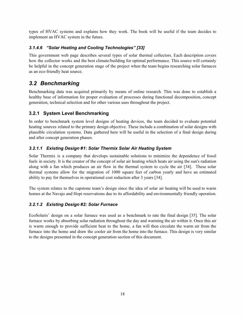
Model 5: Coal Furnace with Insulation, PCM heated airflow, and no people or electrical systems. - Thermostat and fan are the only electrical systems to our knowledge being read. - Six people inhabit the home and produce 2500 Btu/hr-person for 6 hours after 6 PM when
the sun is expected to go out. These people are in fact the model representing PCM releasing latent heat for 6 hours.
- R-13 Insulation in Walls (Fiberglass 3 5/8 is an option) - Vinyl floor finish on the ground base and ceiling insulation - R-3(Mineral Wool of about an inch)
By using equation B1 with the maximum commercial PCM heat capacity of 260 kJ/kg per [44] for model 5, six people who release approximately 2500 BTU/hr-person were used to model a PCM for them to produce about 15,000 BTUs per hour overnight for 6 hours at full capacity and not accounting for losses. Note that the 15,000 BTUs were picked arbitrarily as the midpoint of the coal furnace heat generation.
Also note that models 1 and 3 were only created to compare values between the models with electricity and people and no electricity and people, or for short with models 2 and 4 respectively; however, for cost comparison purposes, models which can be compared due to having like conditions are 2, 4 and 5. While model 5 has theoretical people, this people are being used as a PCM model, hence they are not really accounted for as persons.
Under these characteristics, a cost analysis shown in Appendix B was conducted and it was found out that PCMs do not really reduce the fuel consumption required for heating purposes by a significant amount on the months of December, January and February when compared to model 4 which relies merely on insulation in ceilings and walls.
Additionally, through the use of the initial back of the envelope equations and pricing provided by Rubitherm, it was found that the cost per bulk PCM to heat up the home with 15,000 Btu/hr under ideal conditions over time would require not only significant amounts of PCM, but also their cost would increase rapidly. Depending on the number of hours set for heating a home, PCM weight and value would increase as can be seen in Table 1 below. The table’s prices were based on Rubitherm’s RT 50 due to ease of pricing access. This PCM has a cost of $4.58/kg without including surcharges for ordering less than 150 kg of PCM or installation costs[44]. Moreover, RT 50 has a slightly lower heat capacity than 260 kJ/kg; hence, prices are expected to be higher than those provided in the Table, yet the table serves a good purpose to show PCm’s are expensive materials to use for this project.
Table 1- Price Comparison of PCM with heat Capacity of 260 kJ/kg under optimal heat release(no losses) in bulk configuration to release 15,000 Btus over time [44]
36

Due to all these reasons, PCM integration as a bulk in a heating system was removed as a potential solution, since its costs would exceed the threshold of budget set by our client for small heating efficiency return that could be better achieved with a cheaper alternative such as insulation. 5.3.4 Solar Furnace Selection Process: Jake Shaw The solar furnace was selected based on specification sheets provided by the Solar Rating and Certification Corporation (SRCC) [45]. Solar furnaces were compared based on size and heat output. Glazed flat plate collectors were determined to be the most suitable for this sized home [33]. The required heat output of the collector was found by assuming that the collector would offset half of the power provided by the coal furnace. A typical navajo coal furnace outputs 10,000 Btus/hr to heat up a 500 sq. ft. home [2]. To offset half of this power the furnace will need to output an average of 120,000 Btus for any given day. To find the heat output of the collectors, a certain climate must be specified based on the amount of solar radiation and the difference in temperature between the inside of the home and ambient air. Using solar redbook data in Flagstaff for the coldest month of the year assuming below average sunlight, the amount of solar radiation is 4.7 Kwh/m^2/day [41]. The maximum temperature difference was found to be 23.8 °C, assuming the lowest ambient air temperature is -1.8 °C and the home is maintained at 22 °C [41]. Based on these values, the Fresco glazed flat plate collector manufactured by Trigo Energies was selected. This collector required the least amount of panels and area to meet the required heat output. These panels output 33,029.53 Btus/panel/day and have a gross area of 5.25 m^2 [46]. There would need to be four of these panels to meet the required heat output. Solar redbook data also specifies that maximum solar radiation will be achieved with a south-facing panel at an angle of 50.13° [32]. An approximate price for this panel was found by researching available collectors with a similar output and size. A similar collector was found with an output of 33,500 Btus/panel/day; this collector costs $950 per panel [47]. To offset 50% of the coal furnace output, the solar furnaces alone would cost about $3800. This is obviously much higher than the budget specified by the client. As expected, solar furnaces are very expensive, however the team may consider implementing a single panel to alleviate some of the heat output load from the coal furnace. The results of this analysis provided useful inputs for the home in Equest and also helped prove the impracticality of solar furnaces for implementation in the final design. 5.4 Design Description Per the team’s decision matrix it was found that the most practical solution is to fully insulate the home. This includes ceiling and wall insulation and provides a number of benefits. This would increase the thermal resistance of the home and therefore decrease the amount of BTUs required to heat the space. The reduction in BTUs also correlates to a decreased fuel cost which then translates to higher air quality due to the reduction of fuel costs. This design also leaves some budget left over to the homeowner which can then be used for fuel costs or supplemental heating systems.
37

5.4.1 Qualitative Design Description Initially, team members selected the full-system concept including a Phase Change Material thermal battery incorporated with a fan powered by a photovoltaic panel to circulate air from a solar furnace and eliminate the need for a fuel-burning furnace entirely during standard operating conditions. Team members conducted technical analyses on this design, producing values for the occupancy of the home to accurately convey the results of this design when modeling it in eQUEST. As shown in Edwin Beraud’s technical analyses, the results of the modeling showed a much more substantial drop in energy consumption from insulating the home, compared to the Phase Change Materials. Additionally, analyzing the economic aspects of this design showed a massive cost increase for the design when considering the installation of a PCM-based system, including duct work, materials cost, and the potential need for a backup system. Ultimately, this research led the team to the conclusion that a PCM-based system is not financially viable for this application. In the failure of the initial concept selection to fulfill project financial constraints, the team chose to focus future design work on insulating the home and looking at possible alternative heating sources. This work focuses primarily on producing multiple eligible eQUEST models to compare the effectiveness of different types and locations of insulation, and the consumption and cost of various types of fuel for the main heating source. The current set of models to encapsulate the final design are shown in the CAD Models, bill of materials, and eQUEST models shown below. 5.4.2 CAD Models During modeling phases of this project the team has created many different models of a 500 square foot cinder block home with a coal furnace, considered the datum. The models include, the datum plus wall insulation, the datum plus ceiling insulation, the datum plus fully insulating the home, and the datum plus a solar furnace. For the sake of space the full insulation model (Figure 12) is shown below and will be further discussed in this section of the report.
38

Figure 12 - Full Insulation Model 5.4.3 Bill of Materials (BOM) Based off the materials and tools required to fully insulate a home (Figure 13) the bill of materials was created (Figure 13). This includes the cellulose insulation to be installed in the ceiling and walls, the insulation blower used to install the cellulose and the cost to have a contractor install the insulation. Based off this it is estimated that it would take roughly 1000 dollars to fully insulate a 500 square foot cinder block home assuming that drywall patches are lumped into the cost of the contractor. Bills of Materials for alternative models are available in the Appendix.
Figure 13 - Bill of Materials for Full Insulation Model(Ceiling and Wall)
5.4.4 eQUEST Models The team finalized energy modeling with eQUEST to accurately model energy loss through the home and corroborate this information with local weather data. eQUEST models include inputs including the occupancy schedule of the home, the construction of the home, such as window types, insulation location and amount, and construction materials, and project location, and use embedded weather data and software to output data for the amount of energy required to heat the home. Core assumptions for the datum model in eQUEST are the same as the assumptions for the datum CAD model. The given structure is a 500 square foot home constructed from 6-inch concrete block according to the client’s specifications. The roof includes composite shingles and a construction with 1.2 foot rafters. 3 windows and 1 door are present on the structure, with only one opening on each side of the building. As is clear above, a few assumptions change in these final models from the initial models created in Section 5.3.3. First, the final models specify that the building is constructed out of concrete block as opposed to the red masonry brick in the initial models. The team chose to change this value to best suit the client’s specifications. While budget concerns limit the types of insulation available for use, the team must specify a type of insulation that does not have health and safety risks to fulfill the customer needs. Although fiberglass insulation is the cheapest insulation available commercially, it is subject to convective air movement, which results in degradation of its cumulative R-Value [10]. Fiberglass is not an effective insecticide or pest preventative, can be a a skin and lung irritant, and can be dangerous if not handled properly [10, 32]. With respect to these health and safety concerns in addition to the price constraints, the second cheapest commercial insulation, loose fill cellulose insulation, has been selected as the main insulation type to model in further systems. While cellulose can be damaged by moisture, if pre-treated with borate and
39

installed with vapor retardant material, it has low environmental impact, high energy efficiency, and resistance to airflow [14]. In light of these factors, the team has found that the most effective option for insulation is loose-fill cellulose for cavities in the model home walls and its flat ceiling. The cavities in the walls are assumed to be of 3.5 inches thick in the walls while in the ceiling it is about a foot thick. Using the selected insulation type and thicknesses, the insulation has an R-Value of R-13 on the walls of the home, and an R-Value of around R-42 for the ceiling. These values are based on the specified insulation, which has an R-Value of around R-3.7 per inch, over the specified fill thicknesses of 3.5 inches for the wall and 1 foot for the ceiling. To additionally corroborate this data, weather data research indicates that in a 5B weather zone, the location of the project, the total R-Values obtained are within the expected ranges for this region[11, 33]. After the software receives inputs for all building parameters, it displays a simple 2D and 3D model of the building being evaluated. The 3D model below displays the simple design for the datum the team is using. One window and door can be observed in the rendering, and the other two windows are obscured by the building but present in the model.
Figure 14 - eQUEST Model
eQUEST displays the design’s consumption models in the form of a graph and a table, monthly over the course of a year of operation. The consumption models shown below represent a fully insulated structure, with the required 1 foot of loose fill cellulose insulation in the ceiling and 3.5 inches of loose fill insulation inside the walls. Further information regarding the location and placement of the insulation can be viewed in the CAD model above. Additionally, eQUEST model results for the datum system, the system with insulation only on the ceiling, the system with insulation on the walls, and the fully insulated system with a solar furnace can be viewed in the appendix.
40

Figure 15 - BTU Usage for Full Insulation Model
Figure 16 - Numerical BTU Usage for Full Insulation Model
41

6 IMPLEMENTATION PLAN The CAD and eQUEST models in section 5.4 represent the most current rendition of models used to provide calculations for the project design. The main focus of the project currently is on determining the effectiveness and importance of various building parameters, such as insulation, building materials, and window types The team has been able to create a set of models to compare a design with no insulation to designs with insulation only on the walls, insulation only on the ceiling, and insulation on both surfaces. The insulation type and amount incorporated in these models is the same as that described in section 5.4.4. Additionally, an extra model includes a solar furnace, eliminating coal consumption to heat the home during the day. Bills of Materials for each of these models are available in Appendix C. Specifications from the BOMs and the model consumption graphs allowed team members to create a Decision Matrix (Appendix G), which defines the most viable and effective option as the application of insulation on both the walls and roof. Future modeling goals include comparing double pane and single pane windows and further evaluating potential applications of the specified designs. Additional models could focus on applications of alternate fuels to solar thermal energy and coal, such as wood or propane. The team may attempt to conduct actual testing on a home if it is necessary to obtain accurate values. Securing funding from sponsors is also necessary if the team is to work with Red Feather Development Group to implement the design ideas across the reservation in people’s homes. While the currently emphasized design ideas do not exceed the team’s cost constraint of $1,500 based on their bills of materials, installation and labor costs could be higher than expected due to potential complications such as inconsistencies in home designs and the remote nature of many communities in the region. Work by volunteers or residents themselves could lower these costs and reduce the need for funding. Exploring this possibility is another area for future consideration by team members. Ultimately, future applications of the project depend on the client’s needs at the time, as many factors are currently changing on the reservation due to the recent closure of the Kayenta Coal Mine and Navajo Generating Station. The team will continue to work with the client as closely as possible to account for any future needs or changes in the project goals. In the meantime, the team will focus on continuing to provide accurate models and scenarios that explore and evaluate all possible options for retrofitting homes on the reservation.
42

7 REFERENCES [1] “NAAQS Table”, Clean Air Act, US Environmental Protection Agency. 2018. [Online] [2] M. King, "NAVAJO NATION EPA AIR QUALITY CONTROL PROGRAM INDOOR AIR
QUALITY", [Presentation], 2016. [3] Fleischer, A. (2015). Thermal Energy Storage Using Phase Change Materials. Cham: Springer
International Publishing. [4] Bergman, T., Lavine, A. and Incropera, F. (2017). Fundamentals of heat and mass transfer. 8th ed.
WileyPLUS. [5] J. C. Gomez, “Report: High-Temperature Phase Change Materials (PCM) Candidates for
Thermal Energy Storage (TES) Applications,” Natl. Renew. Energy Lab., vol. 303, no. September 2011, pp. 1–31, 2011.
[6] Lavinia Gabriela SOCACIU, “Thermal Energy Storage with Phase Change Material,” Leonardo
Electron. J. Pract. Technol., no. 20, pp. 75–98, 2012. [7] Z. Zhou, Z. Zhang, J. Zuo, K. Huang, and L. Zhang, “Phase change materials for solar thermal
energy storage in residential buildings in cold climate,” Renew. Sustain. Energy Rev., vol. 48, pp. 692–703, 2015.
[8] S. U. S. Climates, J. Kosny, N. Shukla, and A. Fallahi, “Cost Analysis of Simple Phase Change
Material-Enhanced Building Envelopes in,” no. January, 2013. [9]J. Young, "Insulation R-13 Vs. R-19", Hunker, 2019. [Online]. Available:
https://www.hunker.com/13429493/insulation-r-13-vs-r-19. [Accessed: 27- Apr- 2019]. [10]E. Novotny, "Which Loose Fill Insulation is Best, Cellulose or Fiberglass?",
Windowsonwashington.net, 2019. [Online].Available: https://www.windowsonwashington.net/blog-full/bid/151452/which-loose-fill-insulation-is-best-cellulose-or-fiberglass. [Accessed: 27- Apr- 2019].
[11]"Recommended Home Insulation R– Values | ENERGY STAR", Energystar.gov, 2019. [Online].
Available: https://www.energystar.gov/index.cfm?c=home_sealing.hm_improvement_insulation_table. [Accessed: 27- Apr- 2019].
[12]"Blown-In Insulation for Attics, Sidewalls, 19 lb. Bag | Greenfiber", Greenfiber, 2019. [Online].
Available: https://www.greenfiber.com/products/541-blow-in-low-dust-insulation. [Accessed: 27-Apr- 2019].
[13]E. Guild, "Insulating a Flat Roof", Dengarden, 2019. [Online]. Available:
https://dengarden.com/home-improvement/Insulating-A-Flat-Roof. [Accessed: 27- Apr- 2019].
43

[14]"2019 Average Blown-in Insulation Cost (with Price Factors)", Thumbtack, 2018. [Online]. Available: https://www.thumbtack.com/p/blown-in-insulation-cost. [Accessed: 27- Apr- 2019].
[15]"Attic Insulation | How Much Do I Need?", Insulation Institute, 2019. [Online]. Available:
https://insulationinstitute.org/im-a-homeowner/about-insulation/how-much-do-i-need/. [Accessed: 27- Apr-2019].
[16]L. Wallender, "What You Should Know About Blow-In Cellulose Insulation", The Spruce, 2019.
[Online]. Available: https://www.thespruce.com/cellulose-insulation-basics-1821904. [Accessed: 27-Apr-2019].
[17] W.M. Champion, “Navajo Home Heating Practices, Their Impacts on Air Quality and Human
Health,and a Framework to Identify Sustainable Solutions”. University of Colorado Boulder. 2017. [Online]
[18] HouseLogic, “Home Insulation Types: Advantages and Disadvantages”, REALTORS. [Online] [19] B. K. Hodge, Alternative Energy Systems and Applications. Second edition. Wiley. 2010. [20] K. Jager, O. Isabella, et al., Solar Energy: Fundamentals, Technology, and Systems. Delft University
of Technology. 2014 [21] A. Chel and G. Kaushik, "Renewable energy technologies for sustainable development of energy
efficient building", 2017. [Online]. [22] S. Enibe, "Thermal analysis of a natural circulation solar air heater with phase change material
energy storage", Renewable Energy, vol. 28, no. 14, pp. 2269-2299, 2003. [23] Y. Zhang, K. Du, J. He, L. Yang, Y. Li and S. Li, "Impact factors analysis on the thermal
performance of hollow block wall", Energy and Buildings, vol. 75, pp. 330-341, 2014. [24] F. Jager, Solar Energy Applications in Houses, 1st ed. Luxembourg: A. Wheaton & Co. Ltd., Exeter, 1981. [25] "Types of Insulation", Energy.gov, 2019. [Online]. Available:
https://www.energy.gov/energysaver/weatherize/insulation/types-insulation. [26] S. Partners, "Are Space Heaters More Efficient Than Central Heating | Star",
Starenergypartners.com, 2019. [Online]. Available: https://www.starenergypartners.com/blog/energy-efficiency/are-space-heaters-more-efficient-than-central-heating/. [Accessed: 28- Apr- 2019].
[27] "Active Solar Heating", Energy.gov, 2019. [Online]. Available:
https://www.energy.gov/energysaver/home-heating-systems/active-solar-heating. [Accessed: 28- Apr- 2019].
[28] J. Scott, A. B. Brush, J. Krumm, B. Meyers, M. Hazas, S. Hodges, and N. Villar,“PreHeat:
controlling home heating using occupancy prediction,” Proceedings of the 13th international
44

conference on Ubiquitous computing - UbiComp 11, pp. 281–290, Sep. 2011. [29] M. Gopinath, R. Balaji and V. Kirubakaran, "Cost effective methods to improve the power output of
a solar panel: An experimental investigation," 2014 POWER AND ENERGY SYSTEMS: TOWARDS SUSTAINABLE ENERGY, Bangalore, pp. 1-4, 2014.
[30] “Radiant Heating,” Department of Energy. [Online].Available:
https://www.energy.gov/energysaver/home-heating-systems/radiant-heating.[Accessed: 03-Feb-2019].
[31] M. J. Moran, H. N. Shapiro, D. D. Boettner, and M. B. Bailey, Fundamentals of engineering
thermodynamics, 8th ed. Hoboken, NJ: John Wiley & Sons, Inc., 2018. [32] J. E. Brumbaugh, Audel HVAC fundamentals. Indianapolis, IN: Wiley Pub., 2004. [33] “Solar Heating and Cooling Technologies,” EPA, 19-Dec-2016. [Online]. Available:
https://www.epa.gov/rhc/solar-heating-and-cooling-technologies#Unglazed-Solar-Collectors. [Accessed: 31-Mar-2019].
[34] S. Mazumdar, “Revolutionizing Building Efficiency with Solar ThermiX”, Greenlight Solutions,
2017. [Online]. Available:http://www.glsolutions.org/projects/solarthermix/. [Accessed 04-28-2019].
[35] Solar Air Heater, EcoSolaris, 2018. [Online]. Available: https://ecosolaris.com/en/solar-air-heater/.
[Accessed 04-28-2019]. [36] Radiant Heat, Davis Oil. [Online]. Available:https://www.davisoilkeene.com/radiant-heat/.
[Accessed 04-28-2019]. [37] Buck Stove Model 24 Coal Stove, eFireplaceStore. 2018. [Online].
Available:https://www.efireplacestore.com/bsc-fp24.html. [Accessed 04-28-2019]. [38] Pleasant Hearth LWS-130291 2,200 Sq. Ft. Large Wood Burning Stove. GHP Group. 2018.
[Online]. Available: https://www.ghpgroupinc.com/product-details/LWS-130291.html. [Accessed 04-28-2019]
[39] “Heating a Home with a Propane Furnace”, Propane North Carolina. [Online].
Available:https://www.propanenorthcarolina.com/heat-your-home-propane-vs-electric/propane-furnace/. [Accessed 04-28-2019].
[40] “Screen Absorber Solar Air Heater,” [Online]. 2016. [Accessed 04-28-2019]. [41] “Solar Redbook, AZ” NREL.gov. [Online]. [Accessed: 02-Apr-2019]. [42] L. Cao, D. Su, Y. Tang, G. Fang, and F. Tang, “Properties evaluation and applications of thermal
energy storage materials in buildings,” Renew. Sustain. Energy Rev., vol. 48, pp. 500–522, 2015 [43] https://www.engineeringtoolbox.com/convective-heat-transfer-d_430.html
45

[44]"Rubitherm GmbH", Rubitherm.eu, 2019. [Online]. Available:
https://www.rubitherm.eu/en/index.php/productcategory/organische-pcm-rt. [Accessed: 08- Apr-2019].
[45] “Ratings Summary Page,” SRCC. [Online]. Available:
https://secure.solar-rating.org/Certification/Ratings/RatingsSummaryPage.aspx?type=1. [Accessed: 01-Apr-2019].
[46] ICC-SRCC, “OG-100 ICC-SRCCTM Certified Solar Collector #10002050,” Jul. 2017. [47] “TitanPower-ALDH29 Flat Plate Solar Collector Shop Solar,” Silicon Solar Store, 25-Jun-2018.
[Online]. Available: http://www.siliconsolar.com/product/titanpower-aldh29-flat-plate-solar-collector/. [Accessed: 25-Apr-2019].
[48]"Metabolic Heat Gain from Persons", Engineeringtoolbox.com, 2019. [Online]. Available:
https://www.engineeringtoolbox.com/metabolic-heat-persons-d_706.html. [Accessed: 07- Apr- 2019].
[49] “Grape Solar 1-Module 41.0-in x 27.0-in100-Watt Solar Panel” Available:
[https://www.lowes.com/pd/grape-solar-1-module-41-0-in-x-27-0-in100-watt-solar-panel/1000597657?cm_mmc=shp-_-c-_-prd-_-rpe-_-google-_-pla-_-173-_-sosrenewableenergy-_-1000597657-_-0&kpid&k_clickID=go_625671316_69205550394_330404193807_pla-403529565004_c_1013406&gclid=Cj0KCQjwnpXmBRDUARIsAEo71tTRZ86np1fijtYd7l9zBaGfGNm6FBD1g7KSsG_EMWoDP40gaFvIJ54aAq5CEALw_wcB]
[50] “TitanPower-ALDH29 Flat Plate Solar Collector” Available:
[http://www.siliconsolar.com/product/titanpower-aldh29-flat-plate-solar-collector/] [51] “VIVOSUN 8 inch Inline Duct Booster Fan 420 CFM, Low Noise & Extra Long 5.5' Grounded
Power Cord” Available: [https://www.amazon.com/dp/B01C82T0QC/ref=twister_B07KKCJJ3R?_encoding=UTF8&psc=1]
[52] “MYLAR FLEXIBLE DUCT, 12" DIA., 25 FT., WIRE REINFORCED” Available:
[https://www.spycor.com/Mylar-Flexible-Duct-12-dia-25-ft-wire-reinfo-p/oad12.htm?gclid=Cj0KCQjwnpXmBRDUARIsAEo71tRTS1EwxY1Kr4DZUXPPkD_9j0lW-X3GOTcRWSttLRVJ4i6PrnPmUgAaAhgGEALw_wcB]
[53]"Home : Occupational Outlook Handbook: : U.S. Bureau of Labor Statistics", Bls.gov, 2019.
[Online]. Available: https://www.bls.gov/ooh/construction-and-extraction/insulation-workers.htmhttps://www.bls.gov/ooh/construction-and-extraction/insulation-workers.htm. [Accessed: 28- Apr- 2019].
[53]"Low Dust Cellulose Blown-In Insulation 19 lbs", Homedepot.com, 2019. [Online]. Available:
https://www.homedepot.com/p/GreenFiber-Low-Dust-Cellulose-Blown-In-Insulation-19-lbs-INS541LD/100318635. [Accessed: 28- Apr- 2019].
46

8 APPENDICES 8.1 Appendix A: Calculations for PCM Table A.1 - Properties for PCM flat Plate Biot Number calculation. Note Equations are provided below.
Air Properties @ Film Temperature
Viscosity (Ns/m^2) -μ Density(kg/m^2)- ρ
Prandtl Number (Pr)
0.00001971 1.073 0.703
Parameter Magnitude Units
Initial Temperature (Ti) 27.0 C
Fluid Temperature (To) 80.0 C
Film Temperature (Tf) 53.5 C
Plate Length(L) 0.1035 m
Characteristic Length of Plate (Lc): 0.05175 -
Airflow Speed(u) 3.0 m/s
Thermal Conductivity of Air(kf) 0.02826 W/mK
Thermal Conductivity of Paraffin(kp) 0.24 W/mK
Reynolds Number(Re) 16903.42466 Laminar Flow
Nusselt Number(Nu) 76.76098497
Thermal Coefficient of Air (h) 41.91817266 W/m^2K
Paraffin Plate's Biot Number(Bi) 9.03860598 -
47

Equations A1, A2,A3 and A4 below were used to find the Reynolds(Re) and Nusselt(Nu) values of air along with heat the transfer(h) coefficient and Biot number of paraffin set as a flat plate.
(A1)
(A2)
(A3)
(A4)
8.2 Appendix B: eQUEST Calculations Table B.1 - This is a Btu cost Analysis for the 5 models created. Only blue values can be compared due to similarity in conditions. Model 1 and 3 just serve to be compared with model 2 and 4 respectively, to show that people in thee home have an effect of reducing Btu consumption as well.
(B1) Equation B1 assumes the heat storage capacity of PCMs provided by [44] is set in an hour period and that an average person weighs 160 pounds. Additionally, it is assumed that in a room Temperature of 72F a person in the model home would be at rest producing a heat gain of approximately 350 BTU/hr[48]. This equation was developed to convert PCM Heat Capacity (X) to Btu/(hr-person) for eQUEST Modeling. Note that value of desired energy release per hour should
48

be divided by the result of this equation to set the number of people that will model the PCM.
8.3 Appendix C: Bill of Materials Table C.1 - BOM Model 1 - Wall Insulation
Table C.2 - BOM Model 2 - Ceiling Insulation
Table C.3 - BOM Model 3 - Fully Insulated(Ceiling and Wall)
Table C.4 - BOM Model 4 - Solar Furnace
Note that BOM costs for all models came from multiple sources
49

[10],[32],[14],[11],[49],[50],[51],[52],[53],[54].
8.4 Appendix D: CAD Models
Figure 17 - CAD Model 0 - Datum
50

Figure 18 - CAD Model 1 - Wall Insulation
Figure 19 - CAD Model 2 - Ceiling Insulation
51

Figure 20 - CAD Model 3 - Full Insulation
52

Figure 21 - CAD Model 4 - Solar Furnace
8.5 Appendix E: House of Quality
Figure 22 - House of quality
53
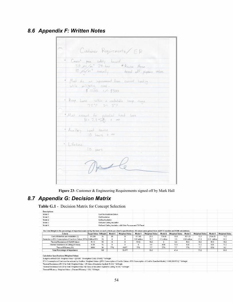
8.6 Appendix F: Written Notes
Figure 23- Customer & Engineering Requirements signed off by Mark Hall
8.7 Appendix G: Decision Matrix Table G.1 - Decision Matrix for Concept Selection
54