
p process - Siemens · p process OPTICHROM ADVANCE PLUS ... Before plugging in a ribbon connectors...
46
GAS CHROMATOGRAPHY p process OPTICHROM ADVANCE PLUS UPGRADE INSTRUCTIONS Installation Manual Edition 1/2007
Transcript of p process - Siemens · p process OPTICHROM ADVANCE PLUS ... Before plugging in a ribbon connectors...

GAS CHROMATOGRAPHY p process
OPTICHROM ADVANCE PLUS UPGRADE INSTRUCTIONS
Installation Manual Edition 1/2007

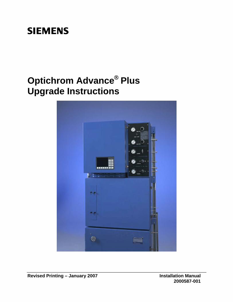
Optichrom Advance® Plus Upgrade Instructions
Revised Printing – January 2007 Installation Manual 2000587-001
Copyright Notice
© 2000-2007 by Siemens
All rights reserved.
This publication is for information only. The contents are subject to change without notice and should not be construed as a commitment, representation, warranty, or guarantee of any method, product, or device by Siemens.
Reproduction or translation of any part of this publication beyond that permitted by Sections 107 and 109 of the United States Copyright Act without the written consent of the copyright owner is unlawful.
Inquiries regarding this manual should be addressed to:
Siemens Energy & Automation, Inc. 7101 Hollister Road Houston, TX 77040 U.S.A.
Trademarks
Advance Maxum is a trademark of Siemens Optichrom Advance is a trademark of Siemens
Table of Contents
Technical Support iiiSafety Practices and Precautions iv
Introduction 1Chapter 1: Overview 1
Hardware Installation 3Chapter 2: Overview 3EC Door Removal and Replacement 4
Database Upgrade 9Chapter 3: Overview 9Setup Analyzer IP Address 11Define Configurable Detectors 12Define an Application 17Hardware ID Address 23Method Development 30
2000587-001 Table of Contents • i/ii

Technical Support
Contacts for Help Siemens provides support for the Maxum System worldwide. Contact information is provided on all Siemens products at the websites noted below. This page provides contact information for Maxum System technical support, training, spare parts, and field service callout. Worldwide e-mail requests can be submitted 24 hours a day, 7 days a week. Service contracts can be established for direct remote phone service for products or for regular field service visits to the site. When the analyzer is mounted and all of the connections are made, a specialist can be sent to assist you in starting up the equipment and preparing it for use. To schedule, contact Customer Service.
To Contact Us:
Siemens AG A&D PI 2 MIS Process Analytics Oestliche Rheinbrueckenstr. 50 76187 Karlsruhe Germany Tel: +49 721 595 4234 Fax: +49 721 595 6375 E-mail: [email protected] www.siemens.com/processanalytics Training Tel: +49 721 595 4035 E-mail: [email protected] Spares Tel: +49 721 595 4288 E-mail: [email protected] Support Tel: +49 721 595 7216 E-mail: [email protected]
Siemens Energy & Automation, Inc. 7101 Hollister Road Houston, TX 77040 USA Tel: +1 713 939 7400 Fax: +1 713 939 9050 E-mail: [email protected] www.usa.siemens.com/ia Training Tel: +1 800 448 8224 (USA) Tel. +1 918 662 7030 (International) E-mail: [email protected] Spares Tel: +1 800 448 8224 (USA) Tel: +1 918 662 7030 (International) Fax: +1 918 662 7482 E-mail: [email protected] Support Tel: +1 800 448 8224 (USA) Tel: +1 918 662 7030 (International) E-mail: [email protected]
Siemens Pte. Limited A&D PI 2 Regional Headquarters The Siemens Center 60 MacPherson Road Singapore 348615 Tel: +65 6490 8702 Fax: +65 6490 8703 E-mail: [email protected] www.siemens.com/processanalytics
Siemens Industrial Automation Shanghai Siemens Process Analytics Ltd., Shanghai PI and Analytics Technical Service Center 12 workshops, 175 XiMaoJing Road Export Processing Zone, SongJiang Shanghai, 201611 Peoples Republic of China Tel: +86-21-5774 9977 Fax: +86-21-6774 7181 E-mail: [email protected] www.ad.siemens.com.cn
Before You Call When contacting Siemens Customer Service for installation technical assistance, the user will need to provide the unit serial number and a detailed description of the problem.
Indicate the installation problem encountered and provide any other information that will aid the customer service representative in correcting the problem.
2000587-001 Safety Practices and Precautions • iii
Safety Practices and Precautions
This product has been designed and tested in accordance with IEC Publication 1010-1, Safety Requirements for Electronic Measuring Apparatus, and has been supplied in a safe condition. This manual contains information and warnings, which have to be followed by the user to ensure safe operation and to retain the product in a safe condition.
Safety First
WARNING statements identify conditions or practices that could result in personal injury or loss of life.
Terms in This Manual
CAUTION statements identify conditions or practices that could result in damage to the equipment or other property.
DANGER indicates a personal injury hazard immediately accessible as one reads the markings.
Terms as Marked on Equipment
CAUTION indicates a personal injury hazard not immediately accessible as one reads the markings, or a hazard to property, including the equipment itself.
This symbol indicates where applicable cautionary or other information is to be found.
Symbols in This Manual
DANGER - High voltage
Protective ground (earth) terminal
ATTENTION - Refer to Manual
Symbols Marked on Equipment
2000587-001 Safety Practices and Precautions • iv
Safety Practices and Precautions, Continued
Before switching on the power, check that the operating voltage listed on the equipment agrees with the available line voltage. Ensure that the power supply switch is to the correct input voltage.
Correct Operating Voltage
Any interruption of the grounding conductor inside or outside the equipment or loose connection of the grounding conductor can result in a dangerous unit. Intentional interruption of the grounding conductor is not permitted.
Danger Arising from Loss of Ground
If it is determined that the equipment cannot be operated safely, it should be taken out of operation and secured against unintentional usage.
Safe Equipment
To avoid fire hazard, use only a fuse of the correct type, voltage rating and current rating as specified in the parts list for your product. Use of repaired fuses or short-circuiting of the fuse switch is not permitted.
Use the Proper Fuse
DO NOT open the equipment to perform any adjustment, measurements, maintenance, parts replacement or repairs until all power supplies have been disconnected.
Safety Guidelines
Only a properly trained technician should work on any equipment with power still applied.
When opening covers or removing parts, exercise extreme care "live parts or connections can be exposed".
2000587-001 Safety Practices and Precautions • v

2000587-001 Introduction • 1/2
Chapter 1
Introduction
Overview
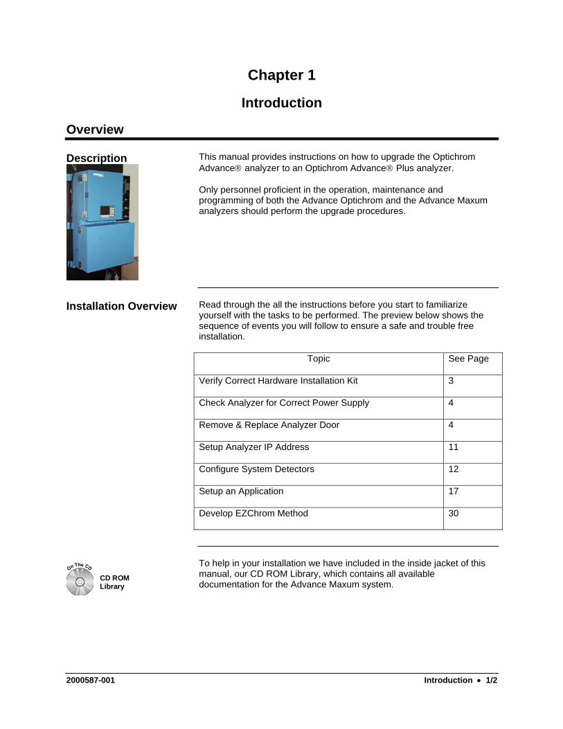
This manual provides instructions on how to upgrade the Optichrom Advance® analyzer to an Optichrom Advance® Plus analyzer.
Description
Only personnel proficient in the operation, maintenance and programming of both the Advance Optichrom and the Advance Maxum analyzers should perform the upgrade procedures.
Read through the all the instructions before you start to familiarize yourself with the tasks to be performed. The preview below shows the sequence of events you will follow to ensure a safe and trouble free installation.
Installation Overview
Topic See Page
Verify Correct Hardware Installation Kit 3
Check Analyzer for Correct Power Supply 4
Remove & Replace Analyzer Door 4
Setup Analyzer IP Address 11
Configure System Detectors 12
Setup an Application 17
Develop EZChrom Method 30
To help in your installation we have included in the inside jacket of this manual, our CD ROM Library, which contains all available documentation for the Advance Maxum system.
CD ROMLibrary
2000587-001 Introduction • 1/2

Chapter 2
Hardware Installation
Overview
This section shows you how to install your new Advance Plus door. Description
Read through the all the instructions before you start to familiarize your self with the tasks to be performed.
Before You Begin
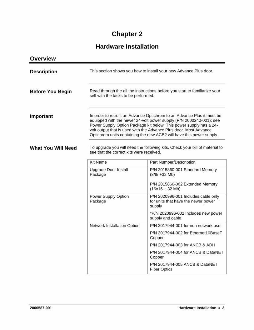
In order to retrofit an Advance Optichrom to an Advance Plus it must be equipped with the newer 24-volt power supply (P/N 2000240-001); see Power Supply Option Package kit below. This power supply has a 24-volt output that is used with the Advance Plus door. Most Advance Optichrom units containing the new ACB2 will have this power supply.
Important
To upgrade you will need the following kits. Check your bill of material to see that the correct kits were received.
What You Will Need
Kit Name Part Number/Description
Upgrade Door Install Package
P/N 2015860-001 Standard Memory (8/8/ +32 Mb) P/N 2015860-002 Extended Memory (16x16 + 32 Mb)
Power Supply Option Package
P/N 2020996-001 Includes cable only for units that have the newer power supply
*P/N 2020996-002 Includes new power supply and cable
Network Installation Option P/N 2017944-001 for non network use
P/N 2017944-002 for Ethernet10BaseT Copper
P/N 2017944-003 for ANCB & ADH
P/N 2017944-004 for ANCB & DataNET Copper
P/N 2017944-005 ANCB & DataNET Fiber Optics
2000587-001 Hardware Installation • 3
EC Door Removal and Replacement
In this section you will remove the Advance Optichrom EC Door and replace with the new Advance Plus door.
Description
When the EC door is opened voltages are present that can cause serious injury to service personnel. Before removing or replacing any component turn off the primary AC power to the analyzer.
Warning
Instructions Step Procedure
1. Shut off all AC primary power to the analyzer,
2. Open the EC door by unsnapping the door’s latches
3. If using a Flame Photometric Detector (FPD) turn off the bias supply switch on the FPD card.
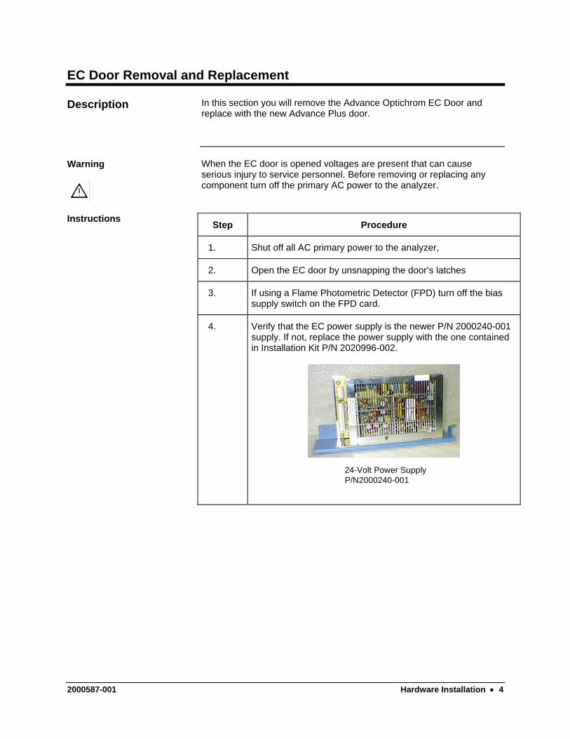
4. Verify that the EC power supply is the newer P/N 2000240-001 supply. If not, replace the power supply with the one contained in Installation Kit P/N 2020996-002.
24-Volt Power SupplyP/N2000240-001
2000587-001 Hardware Installation • 4
EC Door Removal and Replacement, Continued
Step Procedure
5. Remove the metal shield protecting the ACB by first removing the two side mounted thumbscrews and then lefting the shield outward.
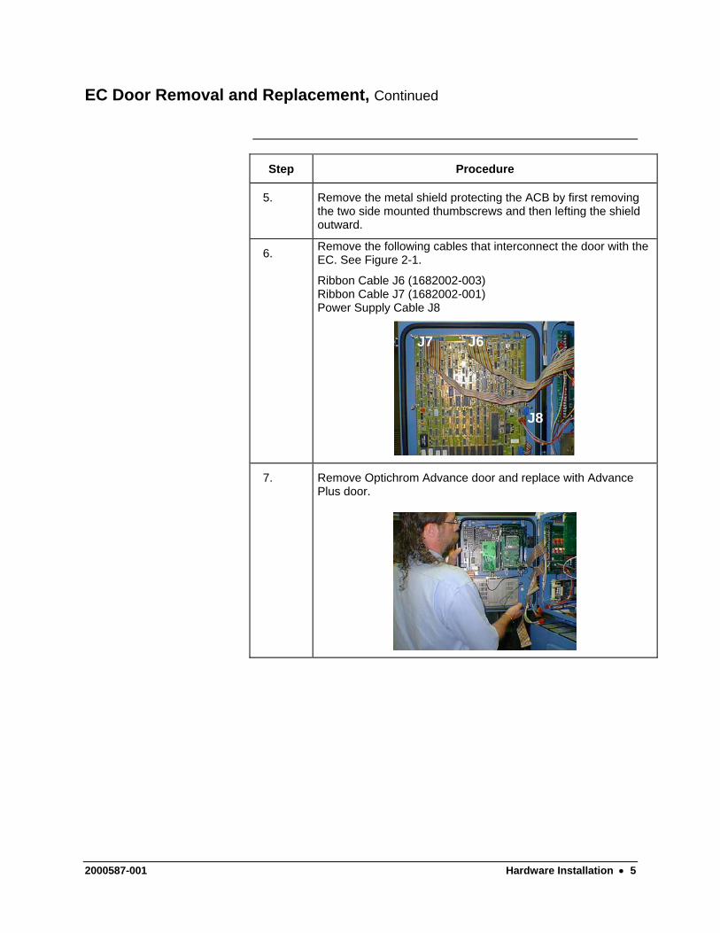
6. Remove the following cables that interconnect the door with the EC. See Figure 2-1.
Ribbon Cable J6 (1682002-003) Ribbon Cable J7 (1682002-001) Power Supply Cable J8
J7J7 J6
J8
7. Remove Optichrom Advance door and replace with Advance Plus door.
2000587-001 Hardware Installation • 5
EC Door Removal and Replacement, Continued
Step Procedure
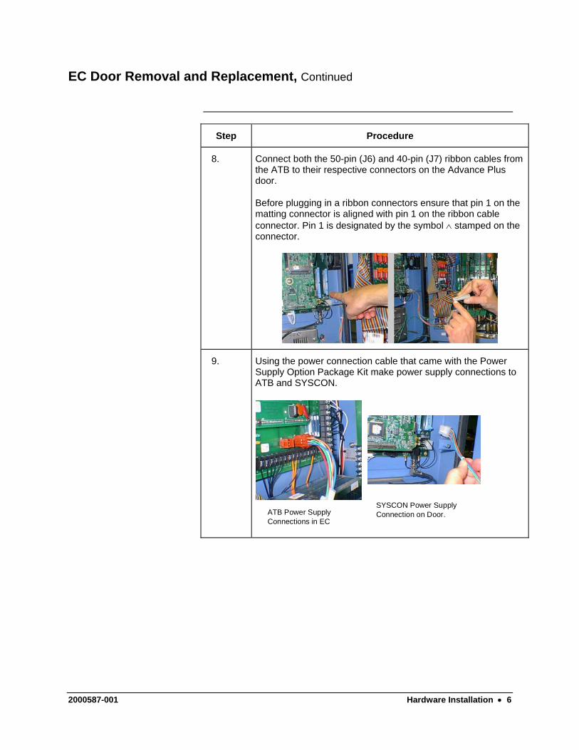
8. Connect both the 50-pin (J6) and 40-pin (J7) ribbon cables from the ATB to their respective connectors on the Advance Plus door.
Before plugging in a ribbon connectors ensure that pin 1 on the matting connector is aligned with pin 1 on the ribbon cable connector. Pin 1 is designated by the symbol ∧ stamped on the connector.
9. Using the power connection cable that came with the Power Supply Option Package Kit make power supply connections to ATB and SYSCON.
ATB Power SupplyConnections in EC
SYSCON Power SupplyConnection on Door.
2000587-001 Hardware Installation • 6
EC Door Removal and Replacement, Continued
Step Procedure
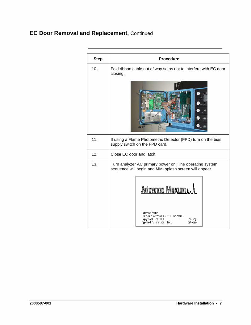
10. Fold ribbon cable out of way so as not to interfere with EC door closing.
11. If using a Flame Photometric Detector (FPD) turn on the bias supply switch on the FPD card.
12. Close EC door and latch.
13. Turn analyzer AC primary power on. The operating system sequence will begin and MMI splash screen will appear.
2000587-001 Hardware Installation • 7
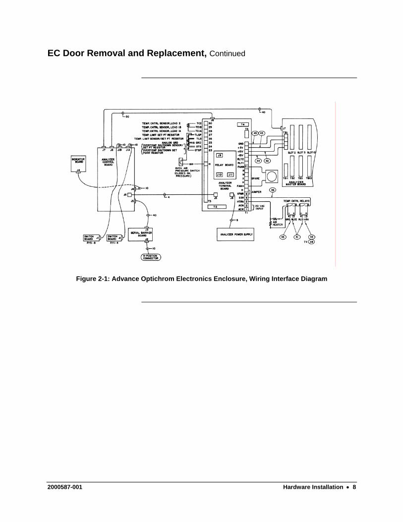
EC Door Removal and Replacement, Continued
Figure 2-1: Advance Optichrom Electronics Enclosure, Wiring Interface Diagram
2000587-001 Hardware Installation • 8
Chapter 3
Database Upgrade
Overview
In this section you will define the Optichrom Advance Plus application data base tables. After completing this section you will be ready to use EZChrom for configuring hardware, and method development.
Description
Only personnel proficient in the operation, maintenance and programming of both the Advance Optichrom and the Advance Maxum analyzers should perform the software upgrade procedures.
Prerequisite Skills
In case you forget how to use the MMI or System Manager a symbol will tell you where to find the information either by looking on the Advance Maxum Library CD or by using the System Manager Help button.
Chapter 3.MaintenanceManual
SystemManager
If you require additional assistance call:
In the United States: (800) 448-8224 Internationally: 001-918-662-7030
What You Will Need • Advance Plus Analyzer networked to PC running the Advance Maxum System Manager Software
• Analyzer’s Custom Documentation Package
• Printout of the Analyzer’s Application Database
• Advance Plus I/O Mapping Chart, Table 3-1 page 22
2000587-001 Database Upgrade • 9
Database Upgrade, Continued
Read through the all the instructions before you start to familiarize your self with the tasks to be performed.
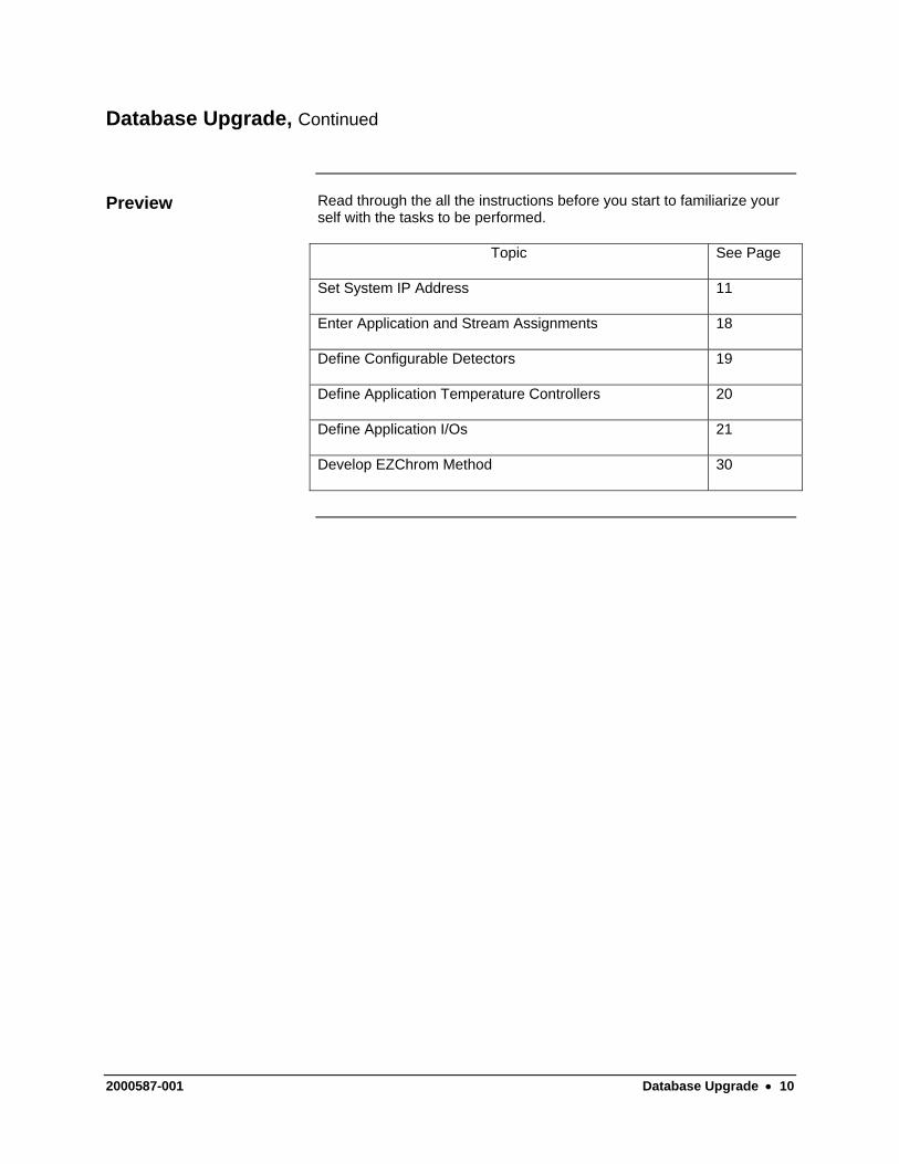
Preview
Topic See Page
Set System IP Address 11
Enter Application and Stream Assignments 18
Define Configurable Detectors 19
Define Application Temperature Controllers 20
Define Application I/Os 21
Develop EZChrom Method 30
2000587-001 Database Upgrade • 10
Setup Analyzer IP Address
In this section you can change the factory default IP Address, and also enter a name for the Advance Plus Analyzer.
Description
All units are shipped with a valid TCP/ICP address. Ask your Network Administrator if you should use this address or use a company assigned address.
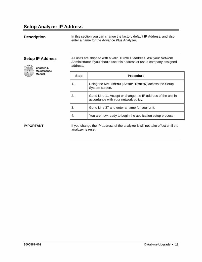
Setup IP Address
Chapter 3.MaintenanceManual Step Procedure
1. Using the MMI (MENU | SETUP | SYSTEM) access the Setup System screen.
2. Go to Line 11 Accept or change the IP address of the unit in accordance with your network policy.
3. Go to Line 37 and enter a name for your unit.
4. You are now ready to begin the application setup process.
If you change the IP address of the analyzer it will not take effect until the analyzer is reset.
IMPORTANT
2000587-001 Database Upgrade • 11
Define Configurable Detectors
In this section you will assign support I/O channels to the analyzer’s spare detector inputs located on the Adapter board or backplane AI boards being used as detector inputs. This assignment is done prior to defining an application detector using that detector channel.
Description
The Advance Plus Analyzer must be networked to a PC running the Advance Maxum System Manager Software
Chapter 3.MaintenanceManual
The MMI can also be used in place of the System Manager to define the Detector Hardware IDs.
The System Detector Configuration dialog box is used to assign support I/O Channels to the spare detector inputs located on the Adapter Board or AI boards located on the back plane. The dialog box allows you to assign various I/O channels reported by the system to a specific hardware ID that corresponds to a system detector channel. Once defined, this new hardware IDs will appear in the detector list when defining application detectors.
Learning Hint
To learn the components of the hardware ID address, see page 23, Hardware ID Address.
The following procedure assigns support I/O channels to a Detectors’ data acquisition inputs.
Instructions
SystemManager
Step Procedure
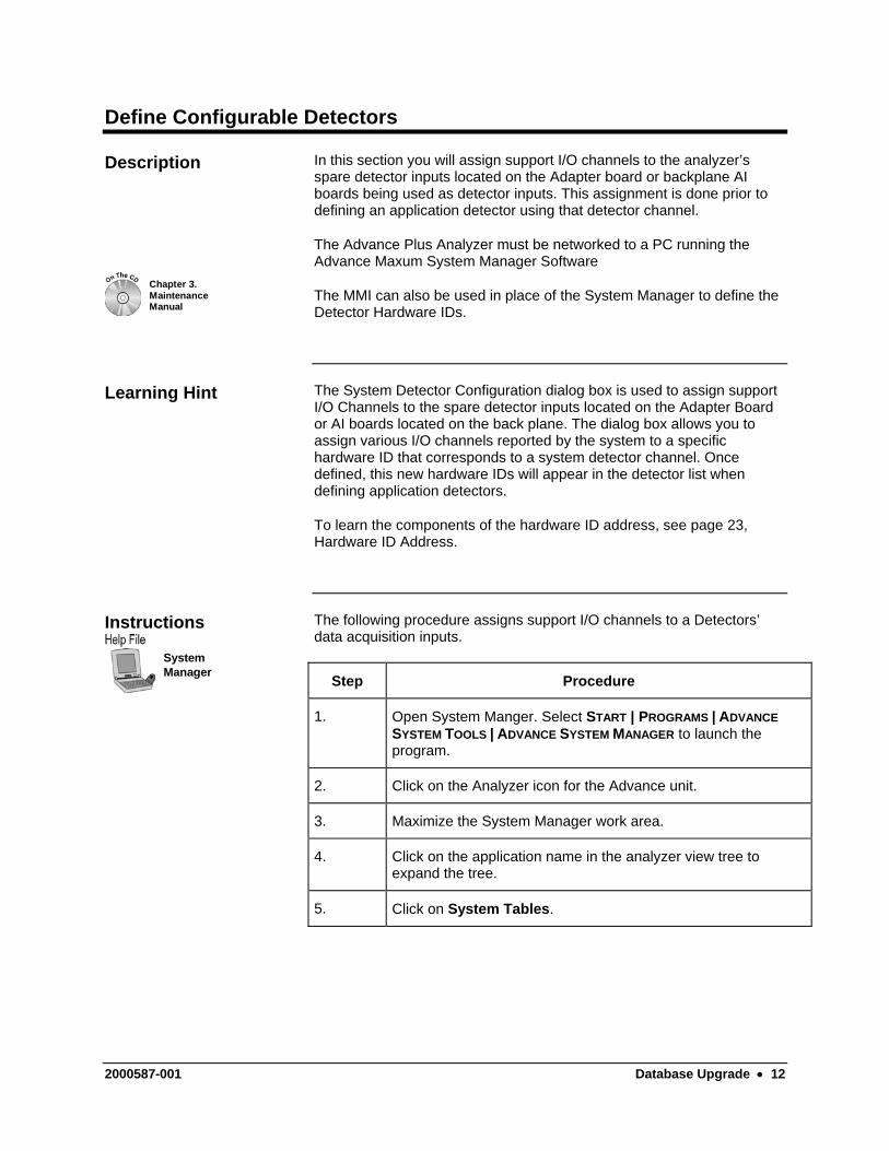
1. Open System Manger. Select START | PROGRAMS | ADVANCE SYSTEM TOOLS | ADVANCE SYSTEM MANAGER to launch the program.
2. Click on the Analyzer icon for the Advance unit.
3. Maximize the System Manager work area.
4. Click on the application name in the analyzer view tree to expand the tree.
5. Click on System Tables.
2000587-001 Database Upgrade • 12
Define Configurable Detectors, Continued
Step Procedure
6. In the Table Name window click on Sys_Detector_Cfg. The password dialog box will appear.
7. Enter password information. For first time users the default is:
Login: Super Password 555.
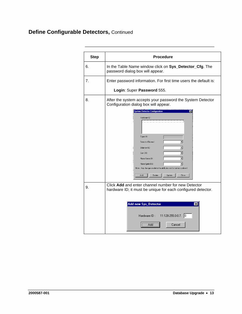
8. After the system accepts your password the System Detector Configuration dialog box will appear.
9. Click Add and enter channel number for new Detector hardware ID; it must be unique for each configured detector.
2000587-001 Database Upgrade • 13
Define Configurable Detectors, Continued
Step Procedure
10. Click Add. The System Detector Configuration dialog box will appear. The Hardware ID window will show the new Detector ID.
11. Click the down ↓ arrow in the Detector Channel window. From the drop down list select the hardware ID string with the correct channel identifier for the detector input.
To determine the correct channel you must be able to interpret the hardware ID number string. Use the Optichrom to Advance Plus I/O Mapping Chart (Table 3-1) and reference page 23, Hardware ID Address. Refer also to your analyzer's Application Drawing Package and Database Tables to determine other identifiers i.e. detector and I/O type, slot and channel ID.
12. Repeat steps 1 through 11 for all detectors that use the spare detector inputs or back plane AI boards for data acquisition.
2000587-001 Database Upgrade • 14
Define Configurable Detectors, Continued
The following examples should aid you in your setup. Examples
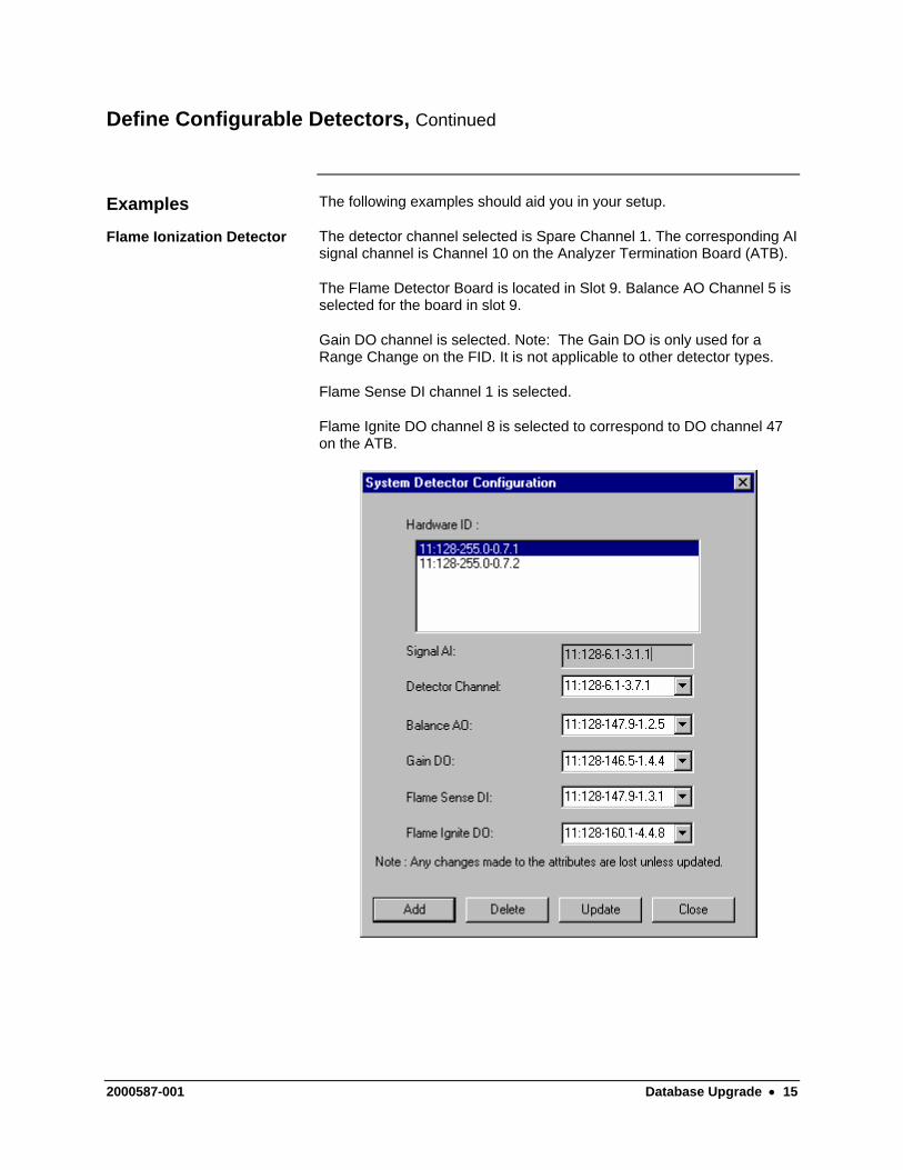
The detector channel selected is Spare Channel 1. The corresponding AI signal channel is Channel 10 on the Analyzer Termination Board (ATB).
Flame Ionization Detector
The Flame Detector Board is located in Slot 9. Balance AO Channel 5 is selected for the board in slot 9.
Gain DO channel is selected. Note: The Gain DO is only used for a Range Change on the FID. It is not applicable to other detector types.
Flame Sense DI channel 1 is selected.
Flame Ignite DO channel 8 is selected to correspond to DO channel 47 on the ATB.
2000587-001 Database Upgrade • 15
Define Configurable Detectors, Continued
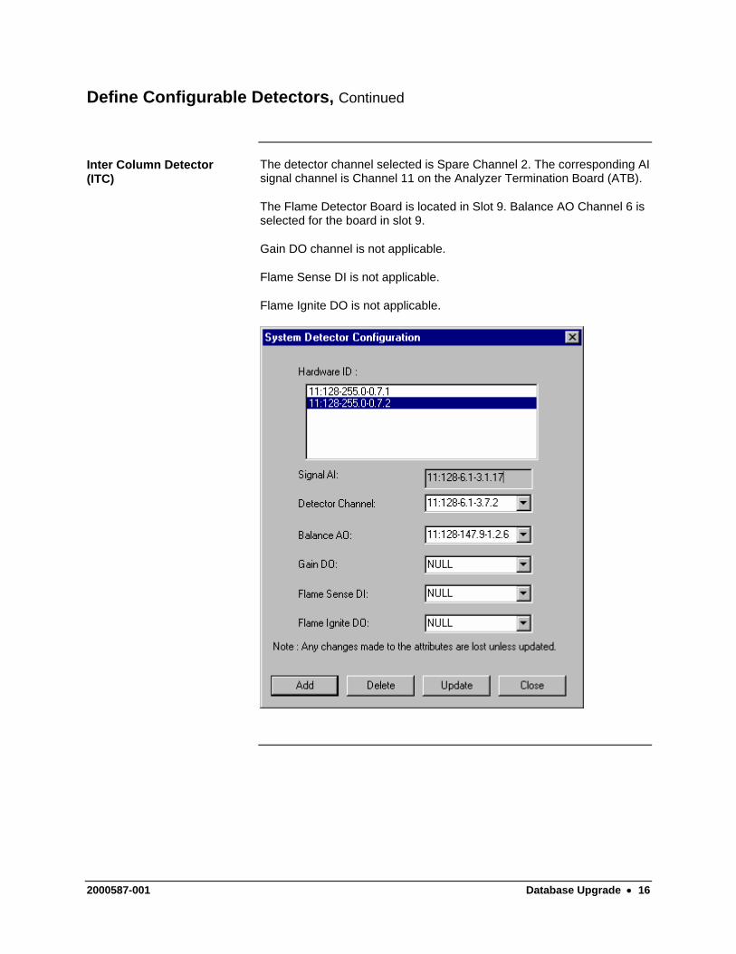
The detector channel selected is Spare Channel 2. The corresponding AI signal channel is Channel 11 on the Analyzer Termination Board (ATB).
Inter Column Detector (ITC)
The Flame Detector Board is located in Slot 9. Balance AO Channel 6 is selected for the board in slot 9.
Gain DO channel is not applicable.
Flame Sense DI is not applicable.
Flame Ignite DO is not applicable.
2000587-001 Database Upgrade • 16
Define an Application
The following procedure uses the System Manager to setup an application and assign streams, detectors, temperature controllers and application I/Os. In the next section you will tie an EZChrom method the application.
Description
The Advance Plus Analyzer must be networked to a PC running the Advance Maxum System Manager Software.
Definitions An application is equivalent to the supporting hardware and consists of hardware channels: detector channel (AI), Solenoid Valve Control Module channel (AO), Electronic Pressure Control channel (DI), Temperature Controller (DO). Streams are defined per application, and are paired up with methods in a sequence. Applications can run only one method at a time and define a single cycle clock. The number of cycle clocks in an Advance Maxum analyzer depends on the number of defined applications. Applications are created in the Advance System Manager.
Application Setup
SystemManager
Step Procedure
1. Open System Manger. Select START | PROGRAMS | ADVANCE SYSTEM TOOLS | ADVANCE SYSTEM MANAGER to launch the program.
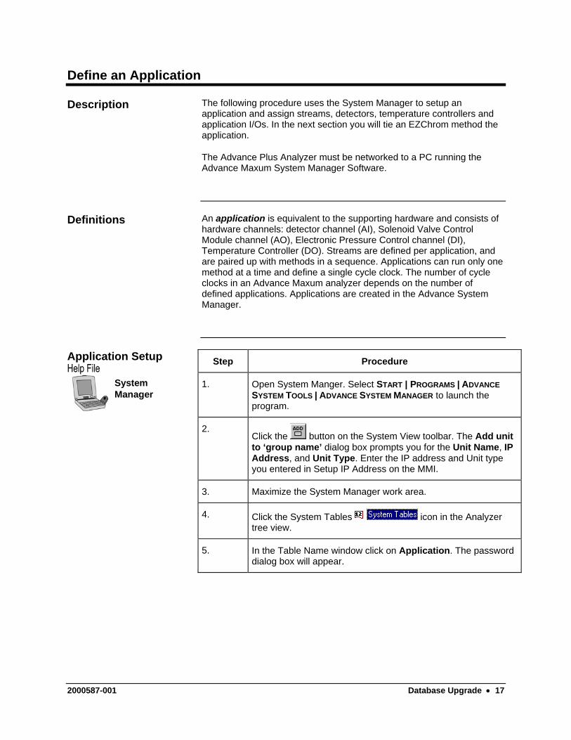
2. Click the button on the System View toolbar. The Add unit to ‘group name’ dialog box prompts you for the Unit Name, IP Address, and Unit Type. Enter the IP address and Unit type you entered in Setup IP Address on the MMI.
3. Maximize the System Manager work area.
4. Click the System Tables icon in the Analyzer tree view.
5. In the Table Name window click on Application. The password dialog box will appear.
2000587-001 Database Upgrade • 17
Define an Application, Continued
Step Procedure
6. Enter password information. For first time users the default is:
Login: Super Password 555.
Tip: To Set Login default:
1. On the main menu bar click System. 2. From the drop down window select Set Default Login and
enter the information 3. Click on ‘Save login and password as default’. 4. Click on Set to exit.
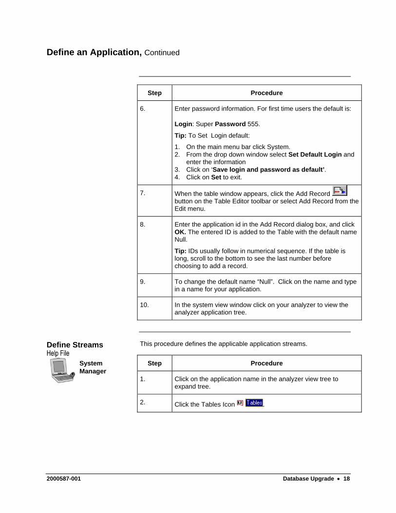
7. When the table window appears, click the Add Record button on the Table Editor toolbar or select Add Record from the Edit menu.
8. Enter the application id in the Add Record dialog box, and click OK. The entered ID is added to the Table with the default name Null.
Tip: IDs usually follow in numerical sequence. If the table is long, scroll to the bottom to see the last number before choosing to add a record.
9. To change the default name “Null”. Click on the name and type in a name for your application.
10. In the system view window click on your analyzer to view the analyzer application tree.
This procedure defines the applicable application streams. Define Streams
SystemManager
Step Procedure
1. Click on the application name in the analyzer view tree to expand tree.
2. Click the Tables Icon .
2000587-001 Database Upgrade • 18
Define an Application, Continued
Step Procedure
3. In the Table Name window click on Streams. The password dialog box will appear.
4. Enter password information. For first time users the default is:
Login: Super Password 555.
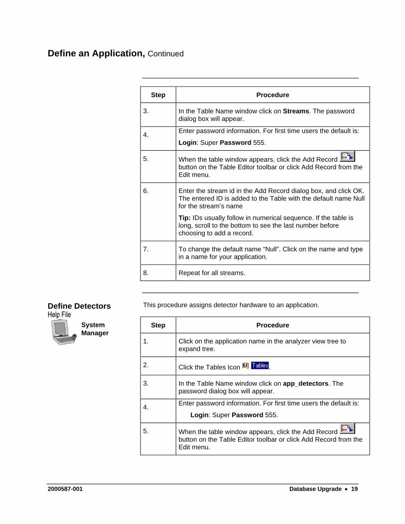
5. When the table window appears, click the Add Record button on the Table Editor toolbar or click Add Record from the Edit menu.
6. Enter the stream id in the Add Record dialog box, and click OK. The entered ID is added to the Table with the default name Null for the stream’s name
Tip: IDs usually follow in numerical sequence. If the table is long, scroll to the bottom to see the last number before choosing to add a record.
7. To change the default name “Null”. Click on the name and type in a name for your application.
8. Repeat for all streams.
This procedure assigns detector hardware to an application. Define Detectors
SystemManager
Step Procedure
1. Click on the application name in the analyzer view tree to expand tree.
2. Click the Tables Icon .
3. In the Table Name window click on app_detectors. The password dialog box will appear.
4. Enter password information. For first time users the default is:
Login: Super Password 555.
5. When the table window appears, click the Add Record button on the Table Editor toolbar or click Add Record from the Edit menu.
2000587-001 Database Upgrade • 19
Define an Application, Continued
Step Procedure
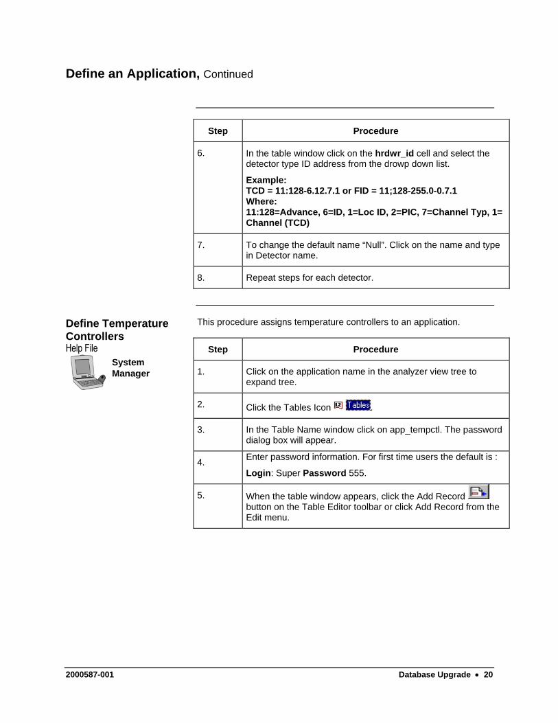
6. In the table window click on the hrdwr_id cell and select the detector type ID address from the drowp down list.
Example: TCD = 11:128-6.12.7.1 or FID = 11;128-255.0-0.7.1 Where: 11:128=Advance, 6=ID, 1=Loc ID, 2=PIC, 7=Channel Typ, 1= Channel (TCD)
7. To change the default name “Null”. Click on the name and type in Detector name.
8. Repeat steps for each detector.
This procedure assigns temperature controllers to an application. Define Temperature Controllers
SystemManager
Step Procedure
1. Click on the application name in the analyzer view tree to expand tree.
2. Click the Tables Icon .
3. In the Table Name window click on app_tempctl. The password dialog box will appear.
4. Enter password information. For first time users the default is :
Login: Super Password 555.
5. When the table window appears, click the Add Record button on the Table Editor toolbar or click Add Record from the Edit menu.
2000587-001 Database Upgrade • 20
Define an Application, Continued
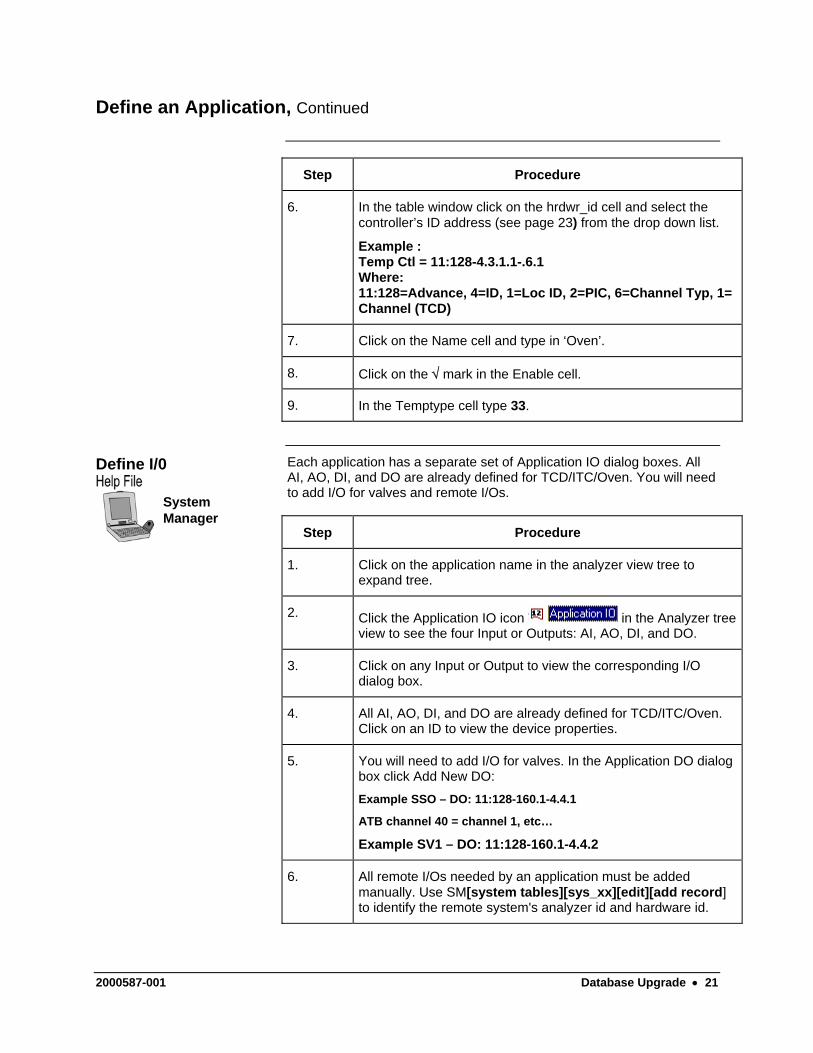
Step Procedure
6. In the table window click on the hrdwr_id cell and select the controller’s ID address (see page 23) from the drop down list.
Example : Temp Ctl = 11:128-4.3.1.1-.6.1 Where: 11:128=Advance, 4=ID, 1=Loc ID, 2=PIC, 6=Channel Typ, 1= Channel (TCD)
7. Click on the Name cell and type in ‘Oven’.
8. Click on the √ mark in the Enable cell.
9. In the Temptype cell type 33.
Each application has a separate set of Application IO dialog boxes. All AI, AO, DI, and DO are already defined for TCD/ITC/Oven. You will need to add I/O for valves and remote I/Os.
Define I/0
SystemManager
Step Procedure
1. Click on the application name in the analyzer view tree to expand tree.
2. Click the Application IO icon in the Analyzer tree view to see the four Input or Outputs: AI, AO, DI, and DO.
3. Click on any Input or Output to view the corresponding I/O dialog box.
4. All AI, AO, DI, and DO are already defined for TCD/ITC/Oven. Click on an ID to view the device properties.
5. You will need to add I/O for valves. In the Application DO dialog box click Add New DO:
Example SSO – DO: 11:128-160.1-4.4.1
ATB channel 40 = channel 1, etc…
Example SV1 – DO: 11:128-160.1-4.4.2
6. All remote I/Os needed by an application must be added manually. Use SM[system tables][sys_xx][edit][add record] to identify the remote system's analyzer id and hardware id.
2000587-001 Database Upgrade • 21
Define an Application, Continued
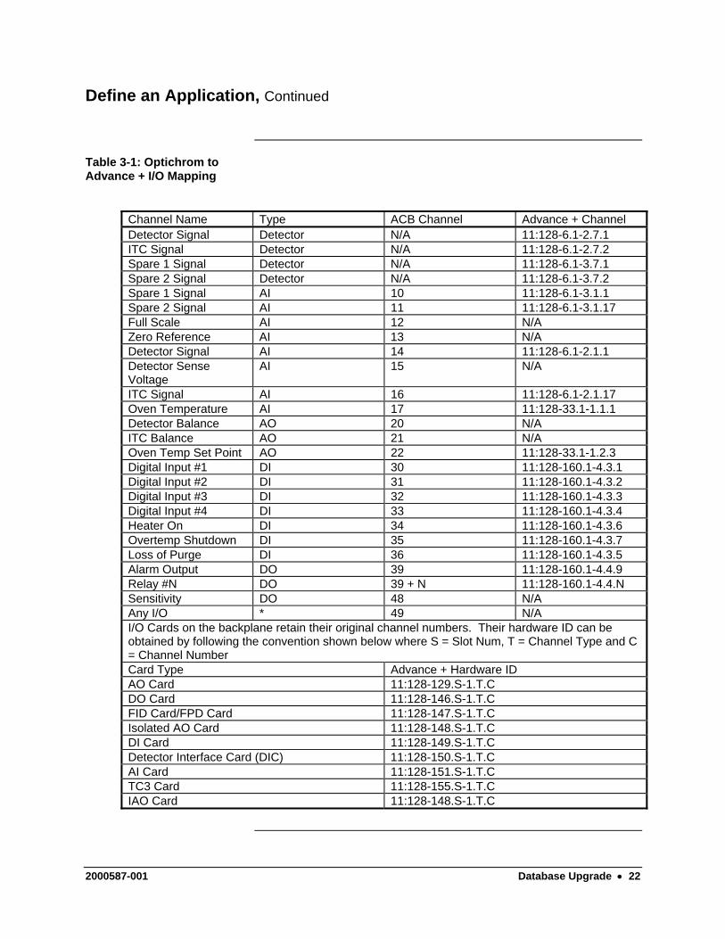
Table 3-1: Optichrom to Advance + I/O Mapping
Channel Name Type ACB Channel Advance + Channel Detector Signal Detector N/A 11:128-6.1-2.7.1 ITC Signal Detector N/A 11:128-6.1-2.7.2 Spare 1 Signal Detector N/A 11:128-6.1-3.7.1 Spare 2 Signal Detector N/A 11:128-6.1-3.7.2 Spare 1 Signal AI 10 11:128-6.1-3.1.1 Spare 2 Signal AI 11 11:128-6.1-3.1.17 Full Scale AI 12 N/A Zero Reference AI 13 N/A Detector Signal AI 14 11:128-6.1-2.1.1 Detector Sense Voltage
AI 15 N/A
ITC Signal AI 16 11:128-6.1-2.1.17 Oven Temperature AI 17 11:128-33.1-1.1.1 Detector Balance AO 20 N/A ITC Balance AO 21 N/A Oven Temp Set Point AO 22 11:128-33.1-1.2.3 Digital Input #1 DI 30 11:128-160.1-4.3.1 Digital Input #2 DI 31 11:128-160.1-4.3.2 Digital Input #3 DI 32 11:128-160.1-4.3.3 Digital Input #4 DI 33 11:128-160.1-4.3.4 Heater On DI 34 11:128-160.1-4.3.6 Overtemp Shutdown DI 35 11:128-160.1-4.3.7 Loss of Purge DI 36 11:128-160.1-4.3.5 Alarm Output DO 39 11:128-160.1-4.4.9 Relay #N DO 39 + N 11:128-160.1-4.4.N Sensitivity DO 48 N/A Any I/O * 49 N/A I/O Cards on the backplane retain their original channel numbers. Their hardware ID can be obtained by following the convention shown below where S = Slot Num, T = Channel Type and C = Channel Number Card Type Advance + Hardware ID AO Card 11:128-129.S-1.T.C DO Card 11:128-146.S-1.T.C FID Card/FPD Card 11:128-147.S-1.T.C Isolated AO Card 11:128-148.S-1.T.C DI Card 11:128-149.S-1.T.C Detector Interface Card (DIC) 11:128-150.S-1.T.C AI Card 11:128-151.S-1.T.C TC3 Card 11:128-155.S-1.T.C IAO Card 11:128-148.S-1.T.C
2000587-001 Database Upgrade • 22
Hardware ID Address
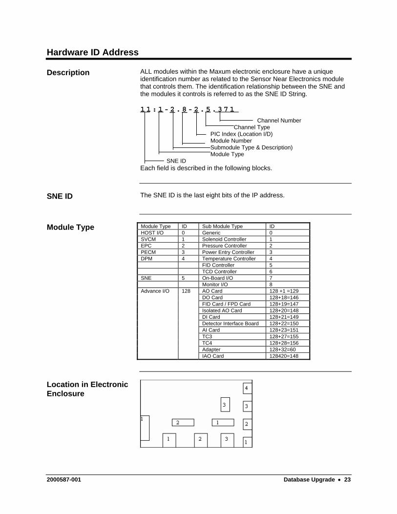
ALL modules within the Maxum electronic enclosure have a unique identification number as related to the Sensor Near Electronics module that controls them. The identification relationship between the SNE and the modules it controls is referred to as the SNE ID String.
Description
11:1-2.8-2.5.371
Channel Number Channel Type PIC Index (Location I/D) Module Number Submodule Type & Description) Module Type
SNE ID Each field is described in the following blocks.
The SNE ID is the last eight bits of the IP address. SNE ID
Module Type Module Type ID Sub Module Type ID HOST I/O 0 Generic 0 SVCM 1 Solenoid Controller 1 EPC 2 Pressure Controller 2 PECM 3 Power Entry Controller 3 DPM 4 Temperature Controller 4 FID Controller 5 TCD Controller 6 SNE 5 On-Board I/O 7 Monitor I/O 8 Advance I/O 128 AO Card 128 +1 =129 DO Card 128+18=146 FID Card / FPD Card 128+19=147 Isolated AO Card 128+20=148 DI Card 128+21=149 Detector Interface Board 128+22=150 AI Card 128+23=151 TC3 128+27=155 TC4 128+28=156 Adapter 128+32=60 IAO Card 128420=148
Location in Electronic Enclosure
2000587-001 Database Upgrade • 23
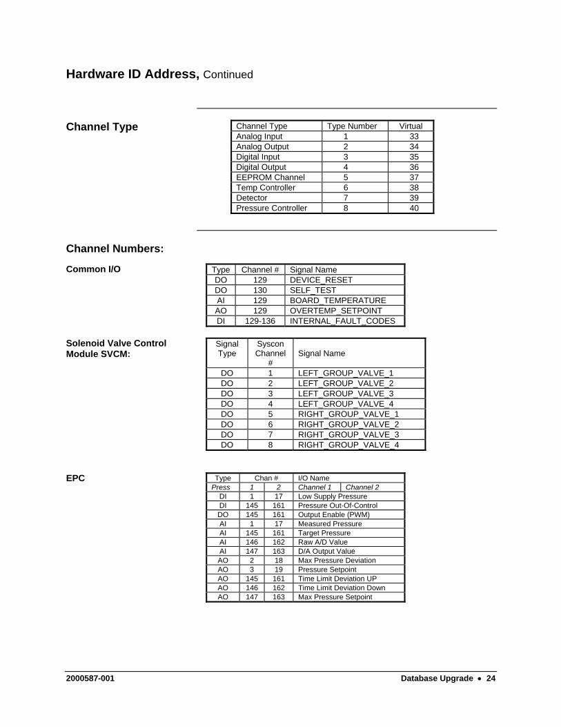
Hardware ID Address, Continued
Channel Type Channel Type Type Number Virtual Analog Input 1 33 Analog Output 2 34 Digital Input 3 35 Digital Output 4 36 EEPROM Channel 5 37 Temp Controller 6 38 Detector 7 39 Pressure Controller 8 40
Channel Numbers:
Common I/O Type Channel # Signal Name DO 129 DEVICE_RESET DO 130 SELF_TEST AI 129 BOARD_TEMPERATURE AO 129 OVERTEMP_SETPOINT DI 129-136 INTERNAL_FAULT_CODES
Solenoid Valve Control Module SVCM:
Signal Type
Syscon Channel
#
Signal Name
DO 1 LEFT_GROUP_VALVE_1 DO 2 LEFT_GROUP_VALVE_2 DO 3 LEFT_GROUP_VALVE_3 DO 4 LEFT_GROUP_VALVE_4 DO 5 RIGHT_GROUP_VALVE_1 DO 6 RIGHT_GROUP_VALVE_2 DO 7 RIGHT_GROUP_VALVE_3 DO 8 RIGHT_GROUP_VALVE_4
EPC Type Chan # I/O Name Press 1 2 Channel 1 Channel 2
DI 1 17 Low Supply Pressure DI 145 161 Pressure Out-Of-Control DO 145 161 Output Enable (PWM) AI 1 17 Measured Pressure AI 145 161 Target Pressure AI 146 162 Raw A/D Value AI 147 163 D/A Output Value AO 2 18 Max Pressure Deviation AO 3 19 Pressure Setpoint AO 145 161 Time Limit Deviation UP AO 146 162 Time Limit Deviation Down AO 147 163 Max Pressure Setpoint
2000587-001 Database Upgrade • 24
Hardware ID Address, Continued
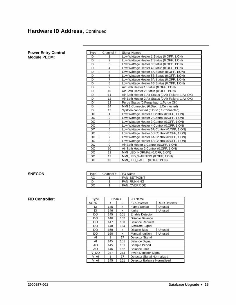
Power Entry Control Module PECM:
Type Channel # Signal Names DI 1 Low Wattage Heater 1 Status (0:OFF, 1:ON) DI 2 Low Wattage Heater 2 Status (0:OFF, 1:ON) DI 3 Low Wattage Heater 3 Status (0:OFF, 1:ON) DI 4 Low Wattage Heater 4 Status (0:OFF, 1:ON) DI 5 Low Wattage Heater 5A Status (0:OFF, 1:ON) DI 6 Low Wattage Heater 5B Status (0:OFF, 1:ON) DI 7 Low Wattage Heater 6A Status (0:OFF, 1:ON) DI 8 Low Wattage Heater 6B Status (0:OFF, 1:ON) DI 9 Air Bath Heater 1 Status (0:OFF, 1:ON) DI 10 Air Bath Heater 2 Status (0:OFF, 1:ON) DI 11 Air Bath Heater 1 Air Status (0:Air Failure; 1:Air OK) DI 12 Air Bath Heater 2 Air Status (0:Air Failure; 1:Air OK) DI 13 Purge Status (0:Purge bad; 1:Purge OK) DI 14 MMI 1 Connected (0:Disc.; 1:Connected) DI 15 SysCon connected (0:Disc.; 1:Connected) DO 1 Low Wattage Heater 1 Control (0:OFF, 1:ON) DO 2 Low Wattage Heater 2 Control (0:OFF, 1:ON) DO 3 Low Wattage Heater 3 Control (0:OFF, 1:ON) DO 4 Low Wattage Heater 4 Control (0:OFF, 1:ON) DO 5 Low Wattage Heater 5A Control (0:OFF, 1:ON) DO 6 Low Wattage Heater 5B Control (0:OFF, 1:ON) DO 7 Low Wattage Heater 6A Control (0:OFF, 1:ON) DO 8 Low Wattage Heater 6B Control (0:OFF, 1:ON) DO 9 Air Bath Heater 1 Control (0:OFF, 1:ON) DO 10 Air Bath Heater 2 Control (0:OFF, 1:ON) DO 11 MMI_LED_NORMAL (0:OFF; 1:ON) DO 12 MMI_LED_WARNING (0:OFF; 1:ON) DO 13 MMI_LED_FAULT (0:OFF; 1:ON)
SNECON: Type Channel # I/O Name AO 1 FAN_SETPOINT DI 1 FAN_RUNNING DO 1 FAN_OVERRIDE
FID Controller: Type Chan # I/O Name DETR 1 2 FID Detector TCD Detector
DI 145 x Flame Sense Unused DI 146 x Ignite Unused DO 145 161 Enable Detector DO 146 162 Disable Balance DO 147 163 Balance Request DO 148 164 Simulate Signal DO 159 x Disable Bias Unused DO 160 x Manual Ignition Unused AI 1 17 Detector Signal AI 145 161 Balance Signal AO 145 161 Sample Period AO 146 162 Balance Limit
V_DO 257 273 Invert Detector Signal V_AI 1 17 Detector Signal Normalized V_AI 145 161 Detector Balance Normalized
2000587-001 Database Upgrade • 25
Hardware ID Address, Continued
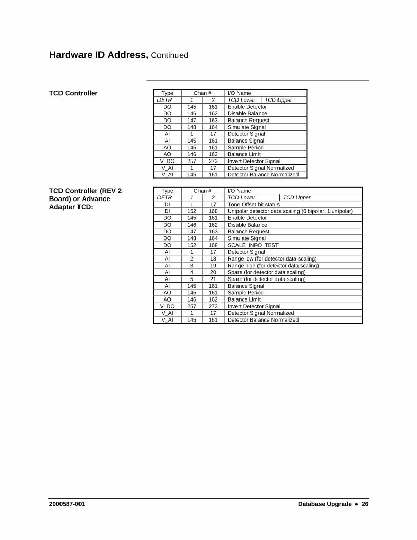
TCD Controller Type Chan # I/O Name DETR 1 2 TCD Lower TCD Upper
DO 145 161 Enable Detector DO 146 162 Disable Balance DO 147 163 Balance Request DO 148 164 Simulate Signal AI 1 17 Detector Signal AI 145 161 Balance Signal AO 145 161 Sample Period AO 146 162 Balance Limit
V_DO 257 273 Invert Detector Signal V_AI 1 17 Detector Signal Normalized V_AI 145 161 Detector Balance Normalized
TCD Controller (REV 2 Board) or Advance Adapter TCD:
Type Chan # I/O Name DETR 1 2 TCD Lower TCD Upper
DI 1 17 Tone Offset bit status DI 152 168 Unipolar detector data scaling (0:bipolar, 1:unipolar) DO 145 161 Enable Detector DO 146 162 Disable Balance DO 147 163 Balance Request DO 148 164 Simulate Signal DO 152 168 SCALE_INFO_TEST AI 1 17 Detector Signal AI 2 18 Range low (for detector data scaling) AI 3 19 Range high (for detector data scaling) AI 4 20 Spare (for detector data scaling) AI 5 21 Spare (for detector data scaling) AI 145 161 Balance Signal AO 145 161 Sample Period AO 146 162 Balance Limit
V_DO 257 273 Invert Detector Signal V_AI 1 17 Detector Signal Normalized V_AI 145 161 Detector Balance Normalized
2000587-001 Database Upgrade • 26
Hardware ID Address, Continued
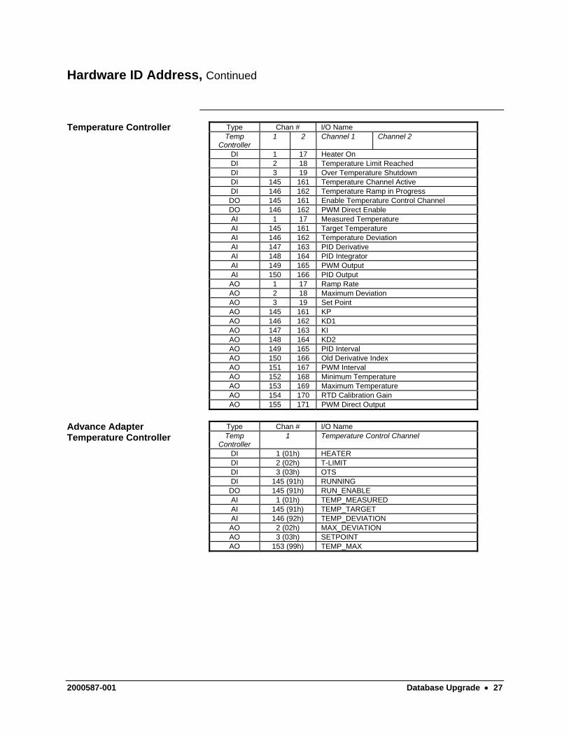
Temperature Controller Type Chan # I/O Name Temp
Controller 1 2 Channel 1 Channel 2
DI 1 17 Heater On DI 2 18 Temperature Limit Reached DI 3 19 Over Temperature Shutdown DI 145 161 Temperature Channel Active DI 146 162 Temperature Ramp in Progress DO 145 161 Enable Temperature Control Channel DO 146 162 PWM Direct Enable AI 1 17 Measured Temperature AI 145 161 Target Temperature AI 146 162 Temperature Deviation AI 147 163 PID Derivative AI 148 164 PID Integrator AI 149 165 PWM Output AI 150 166 PID Output AO 1 17 Ramp Rate AO 2 18 Maximum Deviation AO 3 19 Set Point AO 145 161 KP AO 146 162 KD1 AO 147 163 KI AO 148 164 KD2 AO 149 165 PID Interval AO 150 166 Old Derivative Index AO 151 167 PWM Interval AO 152 168 Minimum Temperature AO 153 169 Maximum Temperature AO 154 170 RTD Calibration Gain AO 155 171 PWM Direct Output
Advance Adapter Temperature Controller
Type Chan # I/O Name Temp
Controller 1 Temperature Control Channel
DI 1 (01h) HEATER DI 2 (02h) T-LIMIT DI 3 (03h) OTS DI 145 (91h) RUNNING DO 145 (91h) RUN_ENABLE AI 1 (01h) TEMP_MEASURED AI 145 (91h) TEMP_TARGET AI 146 (92h) TEMP_DEVIATION AO 2 (02h) MAX_DEVIATION AO 3 (03h) SETPOINT AO 153 (99h) TEMP_MAX
2000587-001 Database Upgrade • 27
Hardware ID Address, Continued
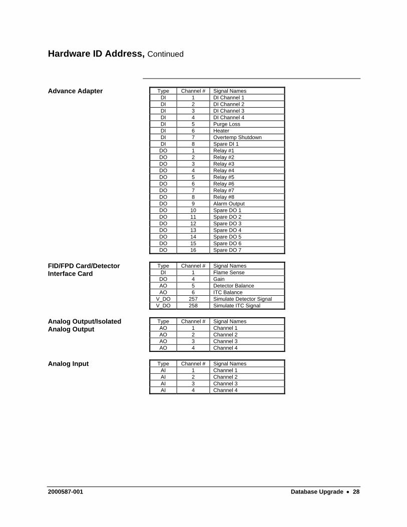
Advance Adapter Type Channel # Signal Names DI 1 DI Channel 1 DI 2 DI Channel 2 DI 3 DI Channel 3 DI 4 DI Channel 4 DI 5 Purge Loss DI 6 Heater DI 7 Overtemp Shutdown DI 8 Spare DI 1 DO 1 Relay #1 DO 2 Relay #2 DO 3 Relay #3 DO 4 Relay #4 DO 5 Relay #5 DO 6 Relay #6 DO 7 Relay #7 DO 8 Relay #8 DO 9 Alarm Output DO 10 Spare DO 1 DO 11 Spare DO 2 DO 12 Spare DO 3 DO 13 Spare DO 4 DO 14 Spare DO 5 DO 15 Spare DO 6 DO 16 Spare DO 7
FID/FPD Card/Detector Interface Card
Type Channel # Signal Names DI 1 Flame Sense DO 4 Gain AO 5 Detector Balance AO 6 ITC Balance
V_DO 257 Simulate Detector Signal V_DO 258 Simulate ITC Signal
Analog Output/Isolated Analog Output
Type Channel # Signal Names AO 1 Channel 1 AO 2 Channel 2 AO 3 Channel 3 AO 4 Channel 4
Analog Input Type Channel # Signal Names
AI 1 Channel 1 AI 2 Channel 2 AI 3 Channel 3 AI 4 Channel 4
2000587-001 Database Upgrade • 28
Hardware ID Address, Continued
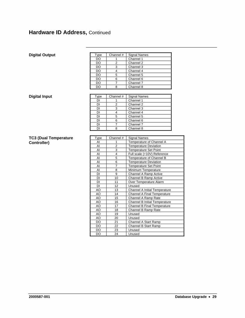
Digital Output Type Channel # Signal Names DO 1 Channel 1 DO 2 Channel 2 DO 3 Channel 3 DO 4 Channel 4 DO 5 Channel 5 DO 6 Channel 6 DO 7 Channel 7 DO 8 Channel 8
Digital Input Type Channel # Signal Names
DI 1 Channel 1 DI 2 Channel 2 DI 3 Channel 3 DI 4 Channel 4 DI 5 Channel 5 DI 6 Channel 6 DI 7 Channel 7 DI 8 Channel 8
TC3 (Dual Temperature Controller)
Type Channel # Signal Names AI 1 Temperature of Channel A AI 2 Temperature Deviation AI 3 Temperature Set Point AI 4 Full scale (+10V) Reference AI 5 Temperature of Channel B AI 6 Temperature Deviation AI 7 Temperature Set Point AI 8 Minimum Temperature DI 9 Channel A Ramp Active DI 10 Channel B Ramp Active DI 11 Over Temperature Alarm DI 12 Unused AO 13 Channel A Initial Temperature AO 14 Channel A Final Temperature AO 15 Channel A Ramp Rate AO 16 Channel B Initial Temperature AO 17 Channel B Final Temperature AO 18 Channel B Ramp Rate AO 19 Unused AO 20 Unused DO 21 Channel A Start Ramp DO 22 Channel B Start Ramp DO 23 Unused DO 24 Unused
2000587-001 Database Upgrade • 29
Method Development
Description
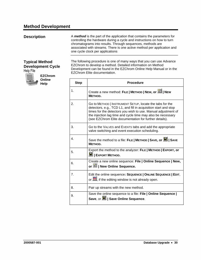
A method is the part of the application that contains the parameters for controlling the hardware during a cycle and instructions on how to turn chromatograms into results. Through sequences, methods are associated with streams. There is one active method per application and one cycle clock per applications
The following procedure is one of many ways that you can use Advance EZChrom to develop a method. Detailed information on Method Development can be found in the EZChrom Online Help Manual or in the EZChrom Elite documentation.
Typical Method Development Cycle
EZChromOnlineHelp Step Procedure
1. Create a new method: FILE | METHOD | NEW, or | NEW METHOD.
2. Go to METHOD | INSTRUMENT SETUP, locate the tabs for the detectors, e.g., TCD L1, and fill in acquisition start and stop times for the detectors you wish to use. Manual adjustment of the injection lag time and cycle time may also be necessary (see EZChrom Elite documentation for further details).
3. Go to the VALVES and EVENTS tabs and add the appropriate valve switching and event execution scheduling.
4. Save the method to a file: FILE | METHOD | SAVE, or | SAVE METHOD.
5. Export the method to the analyzer: FILE | METHOD | EXPORT, or | EXPORT METHOD.
6. Create a new online sequence: File | Online Sequence | New, or | New Online Sequence.
7. Edit the online sequence: SEQUENCE | ONLINE SEQUENCE | EDIT, or , if the editing window is not already open.
8. Pair up streams with the new method.
9. Save the online sequence to a file: File | Online Sequence | Save, or | Save Online Sequence.
2000587-001 Database Upgrade • 30
Method Development, Continued
Step Procedure
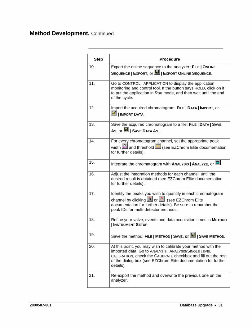
10. Export the online sequence to the analyzer: FILE | ONLINE
SEQUENCE | EXPORT, or | EXPORT ONLINE SEQUENCE.
11. Go to CONTROL | APPLICATION to display the application monitoring and control tool. If the button says HOLD, click on it to put the application in Run mode, and then wait until the end of the cycle.
12. Import the acquired chromatogram: FILE | DATA | IMPORT, or | IMPORT DATA.
13. Save the acquired chromatogram to a file: FILE | DATA | SAVE
AS, or | SAVE DATA AS.
14. For every chromatogram channel, set the appropriate peak width and threshold (see EZChrom Elite documentation for further details).
15. Integrate the chromatogram with ANALYSIS | ANALYZE, or .
16. Adjust the integration methods for each channel, until the desired result is obtained (see EZChrom Elite documentation for further details).
17. Identify the peaks you wish to quantify in each chromatogram channel by clicking or (see EZChrom Elite documentation for further details). Be sure to renumber the peak IDs for multi-detector methods.
18. Refine your valve, events and data acquisition times in METHOD | INSTRUMENT SETUP.
19. Save the method: FILE | METHOD | SAVE, or | SAVE METHOD.
20. At this point, you may wish to calibrate your method with the imported data. Go to ANALYSIS | ANALYSIS/SINGLE LEVEL CALIBRATION, check the CALIBRATE checkbox and fill out the rest of the dialog box (see EZChrom Elite documentation for further details).
21. Re-export the method and overwrite the previous one on the analyzer.
2000587-001 Database Upgrade • 31


Siemens Energy & Automation, Inc. 7101 Hollister Road, Houston, TX 77040 Phone 713-939-7400, Fax 713-939-9050


1/2007 Edition 2000587-001
Siemens Energy & Automation, Inc.
7101 Hollister Road, Houston, TX 77040United StatesPhone +1 (713) 939-7400Fax +1 (713) 939-9050
www.usa.siemens.com/ia


![[06]Image Composition and Matting](https://static.fdocuments.in/doc/165x107/552899da55034675588b47fd/06image-composition-and-matting.jpg)


