p NATIONAL ADVISORY COMMITTEE FOR AERONAUTICS · NATIONAL ADVISORY COMMITTEE FOR AERONAUTICS...
34
p NATIONAL ADVISORY COMMITTEE FOR AERONAUTICS TECHNICAL NOTE 1987 AN ANALYSIS OF SUPERSONIC AERODYNAMIC REATIIG WITH CONTflNUOUS FLUID INJECTION By E. B. Kiunker and H. Reese Ivey Langley Aeronautical Laboratory Langley Air Force Base, Va. Washington December 1949 https://ntrs.nasa.gov/search.jsp?R=19930082730 2018-07-17T07:48:46+00:00Z
-
Upload
vuongxuyen -
Category
Documents
-
view
223 -
download
0
Transcript of p NATIONAL ADVISORY COMMITTEE FOR AERONAUTICS · NATIONAL ADVISORY COMMITTEE FOR AERONAUTICS...

p
NATIONAL ADVISORY COMMITTEE
FOR AERONAUTICS
TECHNICAL NOTE 1987
AN ANALYSIS OF SUPERSONIC AERODYNAMIC REATIIG
WITH CONTflNUOUS FLUID INJECTION
By E. B. Kiunker and H. Reese Ivey
Langley Aeronautical Laboratory Langley Air Force Base, Va.
Washington
December 1949
https://ntrs.nasa.gov/search.jsp?R=19930082730 2018-07-17T07:48:46+00:00Z

NATIONAL ADVISORY COMMITTEE FOR AERONAUTICS
CBi\IICAL NOTE 1987
ø w- 4 AN ANALYSIS OF SUPERSONIC AERODYNAMIC 1
WITH CONTThUOUS FLUID INJECTION 4. By E. B. Kiunker and. H. Reese Ivey
SUMMARY
An analysis of the steady-state aerodynamic heating problem at high-supersonic speeds is made for two-dimensional flows with laminar boundary layers. The aerodynamic heating is shown to be reduced substantially by injecting a small amount of coolant through a porous surface into the boundary layer. The coolant Injection acts in two ways to decrease the aerodynamic heating: First, and most important, the velocity profile is altered such that the rate at which heat is conducted to the surface is reduced and, second, the coolant absorbs an amount of heat which is a function of the difference In temperature between the surface and the coolant. The first effect provides the advantage of cooling by injection over that of simply using a coolant to absorb heat from the surface. Calculations of the stability of the laminar boundary layer show that for a wide range of high-speed flight conditions the boundary layer would remain laminar at all Reynolds numbers according to the stability-theory consideration. The analysis Includes calculations of the cooling requirements and equilibrium surface temperatures for flat plates and for flat porous surfaces with several rates of fluid injection at Mach numbers from 5 to 15 and alti-tudes from sea level to 200,000 feet. Some calculations of the skin friction are also Included.
IWIRODUC TION
The aerodynamic heating problem assumes considerable importance at high-supersonic speeds. S.nger and. edt (reference 1) have calculated the high-speed aerodynamic forces and. equilibrium surface temperatures at extremely high altitudes where the molecular mean free path Is large (free-molecule-flow region) compared with a characteristic body dimension. Although under these conditions the surface temperatures are low, the maximum lift-drag ratios become very small. Consequently, flight at these altitudes may be satisfactory for nonlifting missiles but would be unsatisfactory for steady level flight. On the other hand in the lower atmosphere (say, sea level to 200,000 ft) the lift-drag ratios a.re

2 NACATN1987
considerably larger, but the aerodynamic heating is most acute and some means of surface cooling must be employed at very high speeds. The scope of the present paper is limited to a consideration of the steady-state aerodynamic heating problem at altitudes where the air may be considered a continuum, and particular emphasis is placed on a means of cooling the surface by continuous injection of a fluid in the boundary layer.
Both the heat transfer and the drag coefficients are known to be lower for laminar than for turbulent flows. At supersonic speeds it may be possible to maintain a laminar boundary layer and thus alleviate the aerodynamic heating somewhat. The theoretical investigation of Lees (reference 2) on the stability of the laminar boundary layer in compres-sible flow indicates that the laminar layer is completely stable at all Reynolds numbers at supersonic speeds for a sufficiently low ratio of surface temperature to stream,temperature. Thus, for flow over smooth surfaces small disturbances are damped and a turbulent boundary layer does not develop even at high Reynolds numbers. The possibility of maintaining a laminar flow under these conditions with finite but small disturbances in the boundary layer - that is, maintaining a laminar boundary layer over surfaces that may be employed on a high-speed aircraft - has not been verified experimentally. Experimental verifica-tion of this question aa well as the general conclusions of Lees' work is therefore desirable. Nevertheless, in view of the conclusion of laminar stability for infinitesimal disturbances, it is desirable to investigate theoretically methods of decreasing the aerodynamic heating for laminar flows.
The aerodynamic heating is alleviated somewhat with increasing altitude, but even with laminar flow at altitudes of 200,000 feet the surface temperatures may be excessive, at high-supersonic speeds. An investigation of means of cooling the surface is therefore desirable. .One possible method of cooling is that of injection of a cool fluid through a porous surface into the boundary layer (reference 3). This coolant injection acts in two ways to decrease the aerodynamic heating: First, it alters the velocity profile such that the heat-transfer rate from the fluid'to the surface is reduced and, second, the coolant absorbs an amount of heat which is a function of the difference in temperature between the surface and the coolant. The first effect provides the advantage of cooling by fluid injection over that of simply using.a coolant to absorb heat from the surface.
Injection of the coolant through a porous surface affects the boundary-layer stability in two ways. The direct effect of injecting a fluid in the boundary layer is to alter the velocity profile such that the flow is less stable. The indirect effect is to give a lower surface temperature which in turn tends to make the flow more stable. Actual calculations must determine whether the flow would be stable for given conditions. This question will be discussed in more detail. The blowing

NACATN19870 3
rate should be kept as low as possible, consistent with adequate cooling, since the coolant will probably be carried by the aircraft. Consideration of storage would probably dictate the use of a liquid, and a coolant which has a low temperature and a high heat capacity would be most efficient.
In the present paper, calculations of the steady-state heating of laminar flows are presented for several altitudes from sea level to 200,000 feet; Mach numbers of 5, 10, and 15; and several different surface lengths. Results are presented for a flat porous surface with three rates of coolant injection as well as 'for a flat plate (no blowing). For the case of continuous injection (injection through a porous surface) the calculations were based on a theory for Prandtl number of 1.0, and in all cases the results apply to a flat surface at zero incidence. Included, in the present paper are calculations of the stability of the laminar layer and some calculations of the skin' friction.
- ' , SYMBOLS
Hc average heat transfer rate at surface, Btu/(sq ft)(sec)
Hr . rate at which heat is radiated from surface, Btu/(sq ft)(sec)
Ha ' rate at which heat is absorbed by coolant, Btu/(sq ft)(sec)
heat rate to vaporize coolant, Btu/(sq ft)(sec)
heat-removal rate, Btu/(sq ft)(sec)
T temperature, 0F absolute
x length of surface from leading edge, feet
y coordinate normal to 'surface,. feet
V
k . conductivity, Btu/(sec)(ft)(°F abs.)
Cp heat capacity at constant pressure, Btu/(slug)( OF abs.)
coefficient of viscosity, slugs/(ft)(sec)

11. .NACA TN 1987
p mass density, slugs per cubic foot
L latent heat of vaporization, Btu/slug
Stefan-Boltznirnn constant
(lf.8 x 10-13 Btu/(sec)(sq ft)(°F abs.)1)
u velocity parallel to surface, feet per second
v velocity normal to surface, feet per second.
U1
ratio of heat capacities
M stream Mach number
B Reynolds number
fcI.L Pr Prandtl number (—.
coolant parameterp5v5 iciu1x (-2- \
\)1U1 \J l
nondimensional stream function
D skin friction drag, pounds
skin-friction drag coefficient
Subscripts:
s value at surface
i coolant value
1 stream value
iso isothermal value

NACA TN 1987
5
t stagnation value
re recovery value
ANALYSIS
In order to determine the equilibrium surface temperature of a body in motion through a fluid, a balance between the heat brought to and that removed from the surface must be made. This transfer of enerr occurs mainly through the processes of convection and radiation. The analysis is simplified by considering only nighttime operation. Thus the effects of solar and atmospheric radiation are neglected and only radiation from the aircraft surface is considered. With these restric-tions, then, the heat balance may be written as
+ 11r + EH = 0
(1)
where H is the average heat-transfer rate between the fluid and the surface, Hr is the rate at which ener&y is radiated from the surface, and tH is the rate at which heat is absorbed by the surface. The temperature at which LH = 0 is termed the natural equilibrium temperature. The radiant enerr for a grey body Is readily calculated for a given surface temperature T5 (°F abs.) from the expression
Hr = 0. 9aT 6 ' (2)
where a is the Stefan-Boltzniann constant and the factor 0.9 is chosen as the emissivity for the present calculations. The rate of heat radiation is given as a function of surface temperature in figure 1. The determination of the conductive heat rate requires the solution of the boundary-layer equations. The numerical solutions for high-speed flows are lengthy and tedious, and in order to expedite the work approximate solutions were used. Although this procedure affects the absolute accuracy somewhat, the comparison between the flat plate and a flat surface with fluid injection is unaffected. The solutions for the flat plate and the surface with coolant injection differ in some respects and are, therefore, discussed separately. Specifically, the steady-state heat transfer at supersonic speeds for a flat plate and for a flat porous surface with fluid injection, both at a constant temperature over the.entire surface, are considered herein.
6 NACA TN 1987
Conductive heat transfer. - Throughout the analysis the flow is considered laminar, and the temperatures thus calculated. are later compared with the results of the stability theory of the laminar boundary layer to determine their validity. The average heat rate between the fluid and a surface of unit width and of length x may be written
according to Fourier's law of heat transfer as -
Hc =
(k) dx ()
where k is the conductivity of the fluid, T is the temperature, y is the coordinate normal to the surface, and the subscript a denotes the value at the surface. The quantity T/y is found by solving the dynamic and enerr equations of the boundary layer. Even for a simple configuration such as a flat plate the problem as stated becomes very difficult for high-speed gas flows. Several investigators have calculated velocity and temperature profiles from the boundary-layer equations by various numerical Integration methods (reference 14., for example); however, these calculations are insufficient for the present analysis. The usual method of determining the high-speed heat transfer (references 5 and 6) is to modify the low-speed solutions. This practice is followed herein.
Conductive heat transfer - flat plate. - The usual generalization of the low-speed heat-transfer equations results by employing values of density, viscosity, conductivity, and heat capacity based on surface conditions instead of stream values and by modifying. the temperature potential (reference 5). For laminar flow over a flat plate then the average heat-transfer rate between the fluid and surface is
H = 0 66ks(Psuix 1/2 1/3
c0 ) (Pr) (T5 - Tre) ()
where the subscript 0 denotes the value for a flat plate, p5 is the density at the surface, 1i5 is the viscosity at the surface, Pr is the Prandtl number (taken as 0.7 2), u1 is the stream velocity, and Tre is the recovery (or adiabatic wail) temperature, that is, the temperature an insulated nonradiating surface would assume in an adiabatic flow. •This form of the heat-transfer equation has proved satisfactory at moderate-supersonic speeds, however, it has not been verified experimentally at the high speeds considered herein.

NACATTl987 . 7
The ratio of the temperature rise with no heat transfer to the stagnation-temperature rise is termed the recovery factor. A knowledge of this factor permits the determination of the recovery temperature. In general this factor is dependent upon the geometry of the body and the Prandtl number and is found from experiment or calculation. A value Qf 0.9 - is used herein and the recovery temperature then is found from the relation
Tre = T1 + 0.9(Tt - Ti)
where T1 is the stream temperature and Tt is the stagnation tempera-ture. In order to allow for the variation in the ratio of specific heats with temperature, the stagnation temperature was calculated from a relation derived by quantum statistical methods (reference 6)
M2+STt 1.13 + 0.2(6)
6060 1212 exp[2.2l - 1 exp[21 - i
LTtJ LTtJ
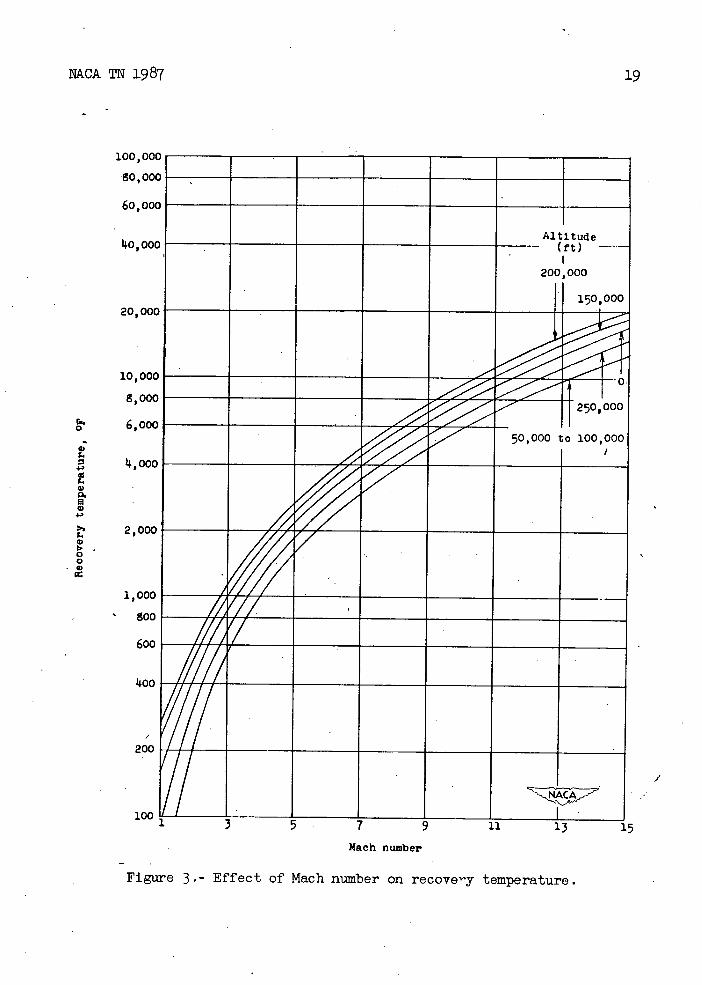
where M is the stream Mach number. Figures 2 and 3 present the variation of stagnation and recovery temperatures, respectively, with Mach number for several altitudes.
The heat balance for laminar flow over a flat plate at several altitudes and Mach numbers was determined from equation (1). The altitude tables of reference 7 were used to determine the stream temperature and density and the viscosity and conductivity coefficients were calculated from Sutherland's equation. The heat absorbed by the surface (iH) for a 10-foot surface length is given as a function of the surface tempera-ture in figure 1 for several altitudes. The natural equilibrium temperature is found from the condition that tH 0. This temperature, for the flat plate (c = o), is given in figure 5 for several altitudes, Mach numbers, and surface lengths. In gneral the equilibrium temperature is found graphically or by trial and error.
Heat balance with continuous fluid injection. - The high natural equilibrium temperatures .of a flat plate at high-supersonic speeds emphasize the need for some adequate means to cool the surface. Injection of a fluid through a porous surface into the boundary layer changes the
velocity profile such that the velocity gradient - at the surface
8 NACATN1987
is decreased. Since the temperature gradient, and thus the heat-transfer rate, is approximately proportional to the velocity gradient, the rate at which heat is conducted to the surface is reduced. A very small rate of fluid injection decreases the aerodynamic heating significantly. Since the quantity of fluid injected is small, the usual boundary-layer equations apply.
If the initial temperature of the fluid injected into the boundary layer is lower than the surface temperature, the coolant will absorb an amount of heat proportional to the temperature difference; furthermore, if the coolant is a liquid, it will absorb. an additional amount of heat proportional to the heat of vaporization. The change in the velocity profile also alters the stability of the boundary layer. In reference 3 it is shown that the fluid injection is destabilizing, but on the other band the effect of the heat transfer is stabilizing. Thus, the net effect of injection and cooling must be accounted for in the stability consideration. For a wide range of conditions the flow is stable in the laminar form. See section entitled "Stability considerations of the laminar boundary layer.'t
For the present analysis it is assumed that the coolant is liquid air and that part of the heat in the boundary layer Is utilized to vaporize the coolant. The heat balance then may be written as
Hc +Ha +Hv +Hr O (7)
where Ha is the rate at which heat is absorbed by the coolant and 11v is the heat rate required to vaporize the coolant. The heat radiated from the porous surface is given by equation (2) and the average value of H is 0
x xdx = ____
Hv = f Lp8V dx = 2x 10 VU1P1X -L0 (8)
where L is the latent heat of vaporization (taken as 2834 Btu/slug), R is the Reynolds number based on stieam condition, p5 is the density
of the coolant, v5 is the velocity normal to the surface, and c a nondimensional flow parameter defined as
= \pll ll

NkCATN1987 9
The parameter arises in the treatment of the dynamic and enerr equations (reference 3). The condition of constant temperature over the surface is satisfied for = Constant.
In a similar manner the average rate at which heat is absorbed by the coolant is found as
Ha =
P5V5c.(Ts - T)dx -
or
Ha = TOT cPi (T s - T) (10)
where c is the specific heat and T is the temperature of the vaporized.
coolt. 'The heat capacity Cpj s taken as 7.712 Btu/(s1)( abs.)
and the temperature T 1 , as li-7° F absolute.
As in the case of the flat plate, the calculition of the heat transfer between the boundary layer and the surface requires a solution of the boundary-layer equations. However, for the case of continuous injection a solution with certain simplifying assumptions is readily determined from known isothermal solutions by a simple quadrature
(reference 3). Then the quantity may be evaluated in terms of
the slope of the velocity profile for the isothermal problem, and the average heat-transfer rate between the boundary layer and surface is readily found from equation (3).
With the assumption that the Prandtl number is unity, the dynamic and energy equations have the same integral in the absence of a pressure gradient and the temperature is related.to the velocity by
= - r - [1 + - - - 22 (11) T1 p T1 LT1 \ 2 2

10
NACA TN 1987
where w is defined as u/u1 and 7 is the ratio of specific heats.
Reference 3 shows that, for flow over a porous surface of uniform temperature with continuous injection, the equations of the compressible flow are of the same form as the isothermal case provided the Prandtl number is unity and the'viscosity varies linearly with temperature. The coordinate then is related to the isothermal value by
ju1P1
-) Y2jw d (12)
where the subscript iso refers to the isothermal value and is a nonditnensional stream function. From equations (11) and (12) the
quantity - (the value at w = 0) can be expressed in terms of the
isothermal values of the slope of the velocity profile and the average convective heat rate is then found as
= -2k3T1 + 7 - 12) - ]
l( 8iso (13a)
or
(dw
dr1J. ' 180
Hc = (Hc) (13b) °•
Ith L' iso
o=0
A quantity equal to four times is tabulated for several values \ di1 J iso
of in reference 8. The quantity (Hc) Is the convective heat
rate for no blowing - that is, for a flat plate. This relation, however,

NACA TN 1987
11
does not give exact agreement with the results previously given for the fiat plate. In order to provide a better basis for comparison of the equilibrium temperatures with and without blowing, the quantity (Hc)p -
- ....- so0
may be- replaced by. H0; therefore, theconvective heat rate with blowing
may be written as
fdw\
= ilco
[1 dw\ (i1)
L isoi
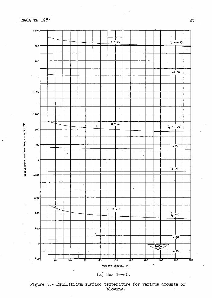
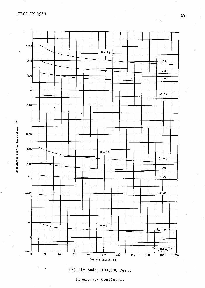
The heat balance for surfaces with coolant injection is determined from equation (7) by employing the foregoing relations. The equilibrium temperatures for several blowing rates, altitudes, and Mach numbers are given as a function of surface length in figure 5.
Throughout this paper, the boundary layer is assumed to be laminar, and this condition may not be fulfilled for some temperatures calculated. The results should then be checked against the stability criterions for laminar boundary layers.
- Stability considerations of the laminar boundary layer.- The direct effect of injection of a fluid in the boundary layer is to destabilize the-flow; whereas, the effect of removing heat is stabilizing. The stability problem then is to determine the minimum critical Reynolds number (that is the Reynolds number at which the flow first becomes unstable) for a given surface temperature, Mach number, and amount of coolant injection. The range in which the heat-transfer calculations are valid can therefore be determined by comparing them with the results of such stability calculations. In reference 2, a detailed consideration of the stability problem is presented for compressible viscous fluids, and in reference 3, an analysis is presented for the specific case of flows over a porous surface with continuous injection.
Instead of determining the minimum critical Reynolds number, it is more convenient to determine the surface temperature required to make the flow stable at all Reynolds numbers for a given Mach number and fluid injection rate. Because of the extreme curvature of the velocity profiles with injection of gas at the wall, the approximate formulas of reference 2 for the minimum critical Reynolds number are not applicable and the iteration method of that paper must be employed. An estimate of the value

12 NACA TN 1987
of mininiuin critical Reynolds number, which will serve as a stability criterion, is obtained by taking the phase velocity to have its maximum possible value. This condition occurs when j (z) = 0.580. (See refer-
ence 2 for the definition of the stability parameters.) For that value of 'p 1 (z), the two branches of the curve of wave number a against R
coincide and hence the phase velocity for each branch approaches the
same value (c = 1 - as R -> ,. M/
The actual calculation consists of choosing a stream Mach number
and fluid injection rate. The vaLue of c is taken as 1 - and. a
trial value of T5/T1 is assumed. Equations (2 li-) and (25) of refer-
ence 2 are used to obtain a zeroeth approximation to the values of
and 'r(z). Figure 9 and equations (28) and (29) of reference 2 are used to determine successive approximations to j(Z). If the final value of 1 (z) 0.580 the assumed value of T 5/T1 was incorrect and a new value must be tried with the corresponding new velocity profile.
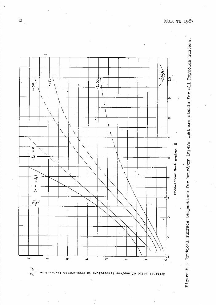
The surface temperature for stability is given as a function of Mach number for a given amount of injection in figure 6, and those temperatures may be compared directly with those found from the heat-transfer calculations. If the calculated surface temperatures are equal to or less than those found from the stability considerations for a given Mach number and coolant injection rate, the flow is stable for all Reynolds numbers. For finite values of the minimum critical Reynolds number somewhat higher Burface temperatures for stability would be allowed.
Skin friction. L The skin friction is readily determined once the velocity profile is known. The skin friction drag is given by
D =tf dx -
= 2ui1.Ls()
CDf= 1 2 --p1u1 x
- 1.I
- i)si5o(15)
NACA TN 1987
13
or, in terms of drag coefficient,
For a linear variation of viscosity with temperature, equation (is) reduces to
CD = 14. fdw
(i6)
iso
The skin-friction drag coefficient calculated from equation (16) is presented in figure 7. This quantity is independent of Mach number because of the linear viscosity-temperature relationship. The skin-friction coefficient decreases with Mach number (Prandtl number less
I-i fTW76 than 1.0) for a viscosity-temperature relation given by - = f -
'kL T1
(See reference 14..) The actual variation with Mach number, however, depends to a large extent on the nature of the viscosity-temperature relation. In general the variation of the drag coefficient with Mach number is small compared to the change due to fluid injection.
DISCUSSION
The results of the steady-state heating analysis for laminar boundary layers are shown in figures 14. and 5. Although the analysis refers specifically to a flat surface at zero incidence, the calculations are indicative of the high-speed heating problem in general. The calculations show that the steady-state temperatures are significantly dependent on the Mach number and altitude and to a lesser extent on the surface length, and that continuous injection of a cool fluid in the boundary layer reduces the equilibrium temperatures substantially.
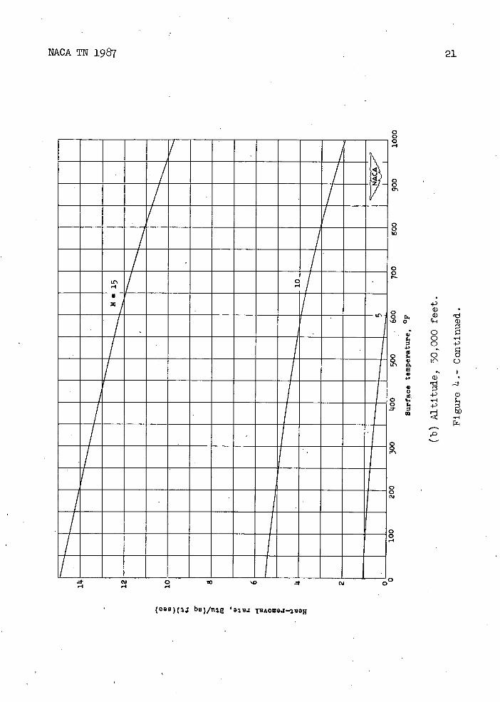
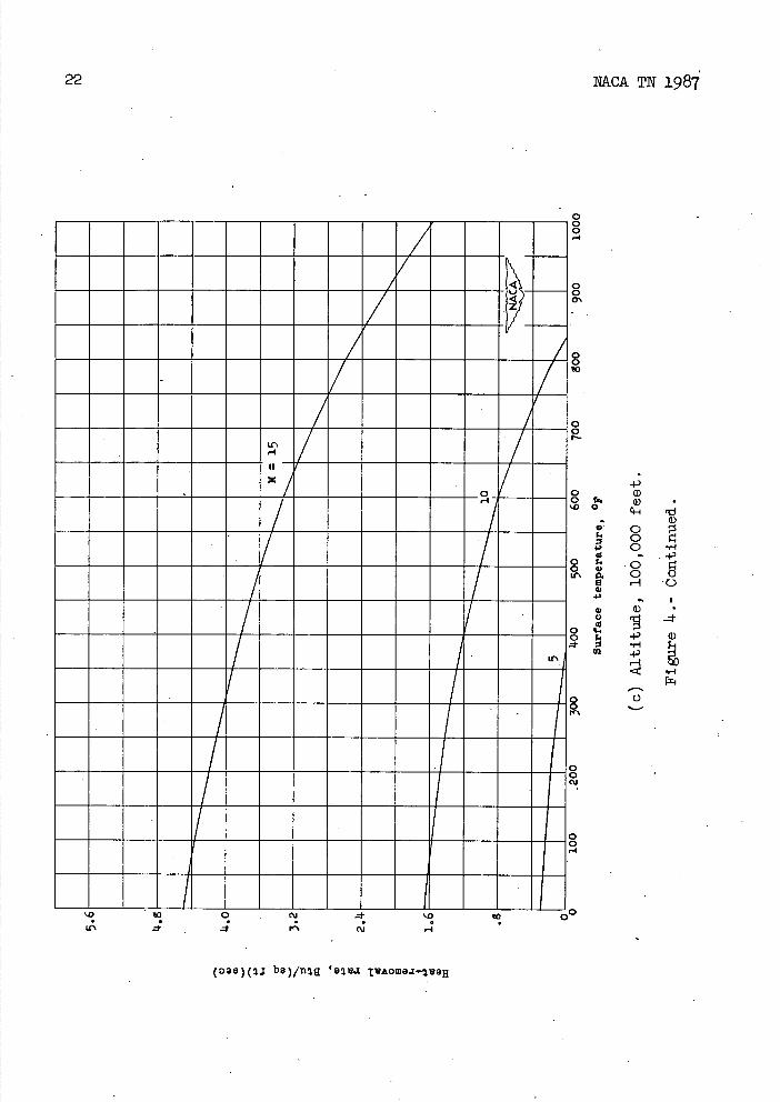
The average amount of heat that must be removed from the surface of a flat plate 10 feet long to maintain a given equilibrium surface temperature is shown in figure 14.. It is readily apparent that the cooling requirements are increased with high speeds and low altitudes. Similar calculations for.other surface lengths indicate that the aero-&ynamnic heating is alleviated somewhat for longer surfaces.

NACA TIc 1987
The calculated equilibrium surface temperatures are presented in figure 5 as a function of the length of -the surface 'for several altitudes, Mach numbers, and coolant injection rates. It is apparent that the temperatures of the surfaces with coolant injection are appreciably lower than those of th flat plate (c1 = 0). For these calculations the coolant was assumed to be liquid air. By choosing a coolant with a higher heat capacity, even, lower temperatures would result. From consideration of a high heat capacity and a low vapor temperature, liquid hydrogen would be a logical choice for the coolant. The injection of foreign gas may alter the stability considerations somewhat, and for that reason no calculations for the case in which hydrogen is used as the coolant are included. Figures i- and 5 indicate that the equilibrium temperatures increase rapidly with Mach number and are highest for low altitudes. The effect of surface length on tIie equilibrium temperatures is hot. very significant. At the lower values of the coolant parameter the short lengths are somewhat hotter, but at the larger values of 'D
there is little variation with length. The amount of coolant injection required to provide a sizeable decrease in the convective heat rate is relatively small. For example, for the most extreme condition considered here (10-ft surface length, sea level, M 15, , = -1), the average mass flow is 0.00l22'slug/(sq ft')(sec). At an altitude of 100,000 feet this value reduces to 0.00012 slug/(sq ft)(sec). At a Mach number of 5 the mass flow is 0.0007 slug/(sq ft)(sec) and 0.00007 slug/(sq ft)(sec) at altitudes of sea level and 100,000 feet, respectively. For a flow parameter of = -0.5 the mass flow would be one-half of those given. The average coolant mass flow decreases for increased surface lengths.
The primary effect of coolant injection is the reduction in the amount of heat transferred from the boundary layer to the surface. This effect may be seen from equation (1 11-). The heat-transfer rate with injection is equal to that for the flat plate times the ratio of the slopes of the velocity profiles, and this ratio is 0.1l92, 0.282, and 0.107 for equal to -0 .5, -0. 75, and -1.0, respectively. Thus, the heat rates at the surface for = -0.5 and -1.0 are approximately 1/2, and. 1/10, respectively, of that of the flat plate.
The fact that the heat-transfer rate with injection is appreciably lower than that of the flat plate suggests the possibility that part , of the boundary layer near the trailing edge could be suckedoff and usedas the fluid to be injected in the boundary layer. This air, of course, is hot and would heat up the boundary layer, but it might be expected that the net effect would be a reduction in surface temperature over that of' a flat plate. A few calculations were made on this basis, but for all conditions calculated the heat added' was found to be large and the net effect was to produce equilibrium surface temperatures slightly higher than those for a flat plate.

NACA 1987. 15
The critical ratio of surface temperature to stream temperature for stability of the boundary layer for all Reynolds numbers is given as a function of the stream Mach number in figure 6. Accurate calculation of the stability at high Mach numbers is difficult and for that reason the results are shown with dashed curves above a Mach number of 5. For all the results in figure 5, however, the stability analysis indicates that the boundary layer is laminar for all Reynolds numbers. The effect of injection on the stability is clearly shown in figure 6. At high-supersonic speeds (say M> 3) the surface radiation alone provides adequate cooling to maintain a laminar boundary layer over smooth surfaces.
The variation of skin-friction drag coefficient with Reynolds number is shown in figure 7. The fact that the skin friction is independent of Mach number arises from the assumption of a linear viscosity-temperature relationship. For other viscosity-temperature relations the skin friction shows some variation with Mach number, and the actual variation depends on the nature of the viscosity-temperature relation. The skin friction is relatively small and decreases with increased blowing rates as long as the boundary layer is laminar.
CONCLUDING REMARKS
• An analysis of the steady-state aerodynamic heating problem at high-supersonic speeds for two-dimensional flows with laminar boundary layers shows that the aerodynamic heating is reduced substantially by injecting a small amount of coolant through a porous surface into the boundary layer. Calculations of the stability of the laminar layer show that for moderate rates of injection the boundary layer Is stable at all Reynolds numbers, and these injection rates provide adequate cooling for many high-speed flight conditions. The calculations show that the equilibrium surface temperatures are significantly dependent on the Mach number and altitude and to a lesser extent on the surface length. In view of the conclusion of laminar stability and the large decrease in aerodynamic heating with a small amount of coolant injection, it is desirable to investigate the problem further both experimentally and analytically since the method appears practical far some high-speed flight applications. Further investigations should include a study of the effectiveness of injecting a fluid into the laminar sublayer to decrease turbulent aerodynamic heating.
Langley Aeronautical Laboratory National Advisory Committee for Aeronautics
Langley Air Force Base, Va., September 29, 191#9

16
NACA TN 1987
REFERENCES
1. S.nger, E., and Bredt, J.: A Rocket Drive for Long Range Bombers. Translation GD-32, Tech. Information Branch, Bur. Aero., Navy Dept., Aug. 191iJ#.
2. Lees, Lester:' The Stability of the Laminar Boundary Layer in a Compressible Fluid. NACA Rep. 876, 1914-7.
3. Lees, Lester: Stability of the Laminar Boundary Layer with Injection of Cool Gas at the Wall. Jep. No. 139, Princeton Univ., Aero. Eng. Lab., May 20, l918.
14-. Von Krmn, Th., and Tsien, H. S.: Boundary Layer in Compressible Fluids. Jour. Aero. Sci., vol. 5, no. 6, April 1938, pp. 227-232.
5. Johnson, H. A., Rubesin, M. W., Sauer, F. M., Slack, E. G., and Possner, L.: A Design Manual for Determining the Thermal Characteristics of High Speed Aircraft. AAF TR No. 5632, Air Materiel Command, Army Air Forces, Sept. 10, 1911.1.
6. Wood, George P.': Calculation of Surface Temperatures in Steady Supersonic Flight. NACA TN 111 11., 1911.6.
7. Warfield, Calvin N.: Tentative Tables for the Properties of the Upper Atmosphere. NACA TN 1200, 1911.7.
8. Schlichting, H., and Bussmann, K.: Exakte Lösungen fir die laminare Grenzschicht mit Absaugung mad Ausbiasen. Bericht 11.2/10, Aero-dynaniisches Institut der T. H. Braunschweig, July 29, 19142.

NACA TN 1987 17
c-i 0
r2.
4-, 0
: 0 .1-I
4-,
Ii 4
G)
c—i 0
pz
0 9 C
Cu -I
(Oa8)(J be)/fl3g 'UOfl8TpB.I JO
C C
C
C C
0 0
I0 —10
Ire,
II. II

18
NACA TN 1987
100,00(
go,00c
6o,00c
, 00c
20,00C
200
100
—A1tjtde (rt)
200,00o
150,000
• _
0-
250,000
100,000
________ ________ ________
50,000 to
• ______
L 1 c a
10,000
g,000 0
6,000
4,
14,000
4,
0
J2,000
1,000
goo
600
11.00
Mach number
Figure 2.- Effect of Mach number on stagnation temperature.
vu
00
00 _________ _________ _________Altitude
DO
_________(rt) -
200,000 _______ ________ H 150,000 DO___
_______ ________ ________ ____ )O_______
, 1250,000 I
______
50,000 to 100,000
/ ______ z ___ ___ of:
3 5 7 9
l0O,C
60, C
110, C
20,0
10,0
g , o
0
6,0
4, 1l, 0
p. A
4.,
2,01
0 C) 0)
1, 0(
6c
1c
2C
10
/
NACA TN 1987
19
Mach number
FIgure 3.- Effect of Mach number on recovery temperature.

NACA TN 1987
0 '-I
(oas)( j be)/fl tAOw.I—aH
IIIIIIIIIII:I
-- 2--- 0
XE
0 0 0
8
ci) H
o 0 00
0 H
8 N- 0
ci) + cii
0 0 0
0 0
0 0
0 0 C',
0 0 '-4
0 0 N-
0 o r. (I) 'd '.00 Il 1)
•.? ° . 0 '-1
0 4-'
6
a, 4,•'
ci) a, zf 0 4-' ci)
o .
u
,0
0 0
NACA TN 1987
21
CU 0 '.0 o -4
(oeB)( b9)/fli 'a.x TAowaz-3eH
22
NACA TN 1987
0 iiiiiiiiiiiiTi IIIIIIIII/IIIII! iiiiiiiiiiiii0 0 Lr
0 0
/U-.'
0 — — 0
0 0 c'J
0 0 -I
iiiiiiiiii iii'.0 10 0 C '.0 10 0'' U-.' - CU
(o38)(1J bB)/n2a 'oz A0waJ—fl
4.)
o ei 'd ci)
• 0 0 c
4.' 0 '-.4
- •4.)
. 0 0 a H '0
4.'.' S
• a)
. .4.) ci)
U) .4.)
'-4 ftc F-.
0

NACA TN 1987
23
0 0 0
0 0
0 0
L(\JJ
0 0
-4-) a) a) ii 'd
'00
0 N1 .' 4-)
0 tr 0 o o w H C)
U ..' I
a) 'd -
C) Q) o '-o -4-)
H U)
fri
0 - 0
U-'
S.
0
0 0 Cu
0 0 -1
0 C Cu Cu
(398)(3J bB)/n '9j1.I IO..t-aH

2
NACA TN 1987
0 0
4
-
-v
0
-.
-
7
/ 0 ____________________7•_____________ 7/
0
/-
IIIIZIIIIIII7II
a) a).
r. 44
o a) o 'd 0 0 H
-' C.) 0
. 0 0 (\J C)
a
+ a)
-1-a 0)
4)
U)
a)
(oae)(2J bB)/n TAOW3.I-2&aH
-koC0 20 '0 bO 80 1u0 120 IbU 180
Surface length, ft -
(a) Sea level.
FIgure 5 . - Equi1Ibri surface temperature for various amounts of blowing.
NACATN 1987
120C
goG
koc.
-k0
-----
-- - --.75
-1.00
------- - - - I410
EEEEEEEEET -1. 0
-14-5
EE
-1
200
120C
0
; goc
4,
0
koc
S 0 0 '4
IC r • -';oc
120C
goc
koC

26
NACA TN 1987
120
go
kG
120
0
go S 0.
S C> 0
S
.4
.0
'4 .4
—kG
go
kG
____._ __ M15
:EEEE 0 -
-1.00
0 - - - - - - - - - - -
-
1111111111111111 20 kO 60 50 100 120 1kG 160 150 200
Surface length, ft
('b) Altltud.e, 50,000 feet.
FIgure 5.- ContInued.
NACA TN 198727
r.. 0
S
S
E 4, 4.
S U 4,
-I 4.
'-4 .4
0
-
__ _____ 11.15
-
-
--
-.50
-
- .-.- - - - -- - -- .75
0 •— ----- ---
- ---
-
- ___ - _±00
-'o------------------------------------_________
1200----- ---------- --_ - -
11-10 - - - - -
iii - - -
- - -
=
- -.50
-.75
11.5-
- - - - = = = - - - Jo = 0_
--
-
IIIIIIIIIIIIIIII 7100 120 140 160 10 200
Surraoe length, rt
(c) Altitude, 100,000 feet.
Figure 5.- Continued.

1200
800
Ioo
0
0
I,
•3
800
p.
a, 0 ' 00
a.0
'-I -.4
—00
koo
0
28
NACA TN 1987
-koo i-0
20 kO 60 80 100 120 1I0 160 180 200
Surtace length, ft
(d) Altitude, 150,000 feet.
Figure 5.- Continued.

NACA TN 1987
29
120C - - - - - - - - - - - -
- - - - - - -
goG - - - - - - - - - - - - - - -
koc —M10
--
- - -. - - - - - - - -
ZOC - - -- - - - - -
---------
- - - - - - -
ll_ -20 0 60 0 100 120 1L40 1,0 1O 2
8urface length, ft
(e) Altitude, 200,000 feet.
Figure 5 . - Conclude&.
D -4
7'
0
.0 a C
.0 0
x a
-' Q)
4.,
£
1!J
NACA TN 1987
4 '-I
----8 '- -I-\- ______;;____ ---- h--
\ \
- - \ \
------
N -
--- -- \ \
-- -N
\ \
-
\
-
---- -\
-
'.0 r4 0
TL r- 'a i.iadwa aeaIa-aazj o ano.iadwa aoeJ.zn8 ;o oa.z

11
NACA TN 1987 31
/0 .? J4 8iO° 234 68/0 234 68/08 234 68/0 Re a/c/s nun7ber, R
Figure 7.- Skin-friction drag coefficient.
NACA-Langley - 12-2-49 - - 900
Abstract
An analysis of the steady-state aerodynamic heating problem at high-supersonic speeds for laminar flows with no pressure gradient shows that the aero-dynamic heating is reduced substantially by injecting a small quantity of coolant into the boundary layer. Consideration of the boundary-layer stability indicates that the laminar boundary layer may be maintained at high-supersonic speeds and. high Reynolds numbers even with fluid injections.
Abstract
An analysis of the steady-state aerodynamic heating problem at high-supersonic speeds for laminar flows with no pressure g:radient shows that the aero-dynamic heating is reduced substantially by injecting a small quantity of coolant into the boundary layer. Consideration of the boundary-layer stability Indicates that the laminar boundary layer may be maintained at high-supersonic speeds and high Reynolds numbers even with fluid injections.
Abstract
An analysis of the steady-state aerodynamic heating problem at high-supersonic speeds for laminar flows with no pressure gradient shows that the aero-dynamic heating is reduced substantially by injecting a small quantity of coolant into the boundary layer. Consideration of the boundary-layer stability indicates that the laminar boundary layer may be maintained at high-supersonic speeds and high Reynolds numbers even with fluid injections.
Abstract
An anaiysis of the steady-state aerodynamic heating problem at high-supersonic speeds for laminar flows with no pressure gradient shows that the aero-dynamic heating Is reduced substantIally by injecting a small quantity of coolant into the boundary layer. Consideration of the boundary-layer stability indicates that the laminar boundary layer may be maintained at high-supersonic speeds and high Reynolds numbers even with fluid Injections.
NACA TN 1987

Mach Number Effects - Wing Sections 1.2.1.8
S
An Analysis of Supersonic Aerod.ynainic Heating with Continuous Fluid. Injection.
By E. B. Kiunicer an1 H. Reese Ivey.
NACA TN 1987
December 1911.9
(Abstract on Reverse Side
Xlunker, E. B., and. Ivey, H. Reese S
An Analysis of Supersonic Aero&ynanLic Heating with Continuous Fluid Injection.
By E. B. Kiunker and. H. Reese Ivey
NACA TN 1987
Decenixer 1911-9
Abstract on Reverse Side
-7-