P E C TRU S M MICROWAVE INC. - RF, Microwave ...micro.apitech.com/pdf/databook_dro.pdfpulling in ppm...
15
MICROWAVE A Spectrum Control Business S P E C T R U M INC.
Transcript of P E C TRU S M MICROWAVE INC. - RF, Microwave ...micro.apitech.com/pdf/databook_dro.pdfpulling in ppm...
MICROWAVEA Spectrum Control Business
SPECTRUM
INC
.

DIELECTRIC RESONATOR OSCILLATORS
779
SPECTRUM MICROWAVE • 2144 Franklin Drive N.E. • Palm Bay, Florida 32905 • Phone: (888) 553-7531 • Fax: (888) 553-7532 SPECTRUM CONTROL GmbH • Hansastrasse 6 • 91126 Schwabach, Germany • Phone: (49)-9122-795-0 • Fax: (49)-9122-795-58
DR
Os
MICROWAVEA Spectrum Control Business
SPE
CTRUM
INC
.
www.specwave.com
Free Running, Mechanically Tuned
MechanicalTuning BW(MHz)
Model Number Frequency
MDR2100 +10+20
2.5 - 6.06.0 - 21.0
AFC Voltage Tunable
MDR3100 2.5 - 6.06.0 - 21.0
+10+20
AFC Voltage Tunable - For Fiber Optic Clock Recovery Applications
MDR30019.9532810.667
+25
Phase Locked, Internal Reference
+10+20
3.0 - 6.06.0 - 21.0MDR5100
MDR6100 3.0 - 6.06.0 - 21.0
+10+20
Free Running, Mechanically Tuned, Moisture Sealed
MDR2560 4.5 - 16.0 +10
Phase Locked, Internal Reference - For LMDS Applications
MDR5530 9.0 - 13.0 -
12 GHz
-118
-117
-116
-110
-114
-110
-114
OutputPower(dBm)
+10
+10
+10
+11
+13
+17
+13
2.5 GHz
-130
-125
-128
-
-120
-
-124
6 GHz
-124
-122
-122
-
-120
-
-120
20 GHz
-113
-111
-108
-
-105
-
-105
Phase Locked, External Reference
OperatingTemp (oC)
-20 to +65
-40 to +85
-20 to +65
-10 to +80
-20 to +65
-40 to +85
-20 to +65
Phase Noise @ 100kHz offset
DRO Selection Guide

SPECTRUM MICROWAVE • 2144 Franklin Drive N.E. • Palm Bay, Florida 32905 • Phone: (888) 553-7531 • Fax: (888) 553-7532 SPECTRUM CONTROL GmbH • Hansastrasse 6 • 91126 Schwabach, Germany • Phone: (49)-9122-795-0 • Fax: (49)-9122-795-58
780
MICROWAVEA Spectrum Control Business
SPECTRUM
INC
.
www.specwave.com
Dielectric Resonator Oscillator
The following pages contain the specifications for Spectrum Microwave stabilized signal sources.Shown are basic free-running oscillators, oscillators with electronic tuning that can be modulated orphase-locked by the user, and phase-locked oscillators using both internal and external referencesources. The Spectrum Microwave line of stabilized oscillators is designed for use in systems requiringhigh frequency stability with low phase noise, low microphonics, small size, and low power drain.Typical applications include microwave radio links, satellite terminals, radar beacons, transponders,ECM receivers, BITE oscillators, and frequency synthesizers. The following paragraphs discuss the general characteristics of these oscillators. We urge you to call us to discuss your needs or e-mail us at [email protected] so that we may work together to provide the best oscillator solution.
Design ApproachSpectrum Microwave stabilized oscillators use a bipolar transistor or GaAs FET in conjunction with aresonator made from a low loss ceramic. In an oscillator design, the transistor and resonator can generate stable, fixed-frequency signals from 2.5 to 26 GHz. The oscillators are available in various configurations. Free-running DROs are mechanically tunable. Voltage tunable DROs are available formodulation, AFC, or phase-locking applications. The units are also available phase-locked to either aninternal crystal or external reference. Phase-locked units exhibit excellent phase noise performance andtemperature stability.
Mechanical TunabilityFree-running DROs can be mechanically tuned over as much as a 5 percent bandwidth before competing modes become a problem. For communication uses, frequency stability requirements typically limit the tuning range to 0.2 to 0.3 percent.
Power OutputTypical power outputs are 20 to l00 mW in the 2.5 MHz to 6 GHz range, decreasing to 10-20 mW inthe 15 to 26 GHz range. Higher output powers can be achieved either by using higher powertransistors in the oscillator or by following the oscillator with an internal amplifier.
Power variation over a 0 to +50°C range at a fixed frequency is typically ± 1 dB without an oven and± a few tenths of a dB in an ovenized oscillator.
Frequency Stability with Temperature VariationFree running oscillators exhibit temperature coefficients on the order of 5 ppm/°C for wide mechanicaltuning ranges and 3 ppm/°C for narrow mechanical tuning ranges of a few tenths of a percent.
Ovenized free running oscillators can be built with ± 10 ppm stability or better over -20ºC to +65°Cambient temperature range.
Phase locked units have stabilities related to the crystal reference and are typically ±10 to ± 20 ppmfor standard crystals. Ovenized crystals can reduce stability variation to less than ±5 ppm.
DRO Introduction
781
SPECTRUM MICROWAVE • 2144 Franklin Drive N.E. • Palm Bay, Florida 32905 • Phone: (888) 553-7531 • Fax: (888) 553-7532 SPECTRUM CONTROL GmbH • Hansastrasse 6 • 91126 Schwabach, Germany • Phone: (49)-9122-795-0 • Fax: (49)-9122-795-58
DR
Os
MICROWAVEA Spectrum Control Business
SPE
CTRUM
INC
.
www.specwave.com
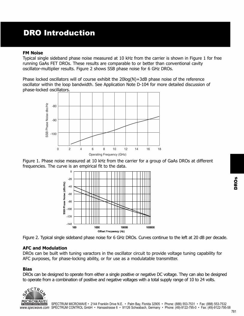
Figure 2. Typical single sideband phase noise for 6 GHz DROs. Curves continue to the left at 20 dB per decade.
AFC and ModulationDROs can be built with tuning varactors in the oscillator circuit to provide voltage tuning capability forAFC purposes, for phase-locking ability, or for use as a modulatable transmitter.
BiasDROs can be designed to operate from either a single positive or negative DC voltage. They can also be designedto operate from a combination of positive and negative voltages with a total supply range of 10 to 24 volts.
FM NoiseTypical single sideband phase noise measured at 10 kHz from the carrier is shown in Figure 1 for freerunning GaAs FET DROs. These results are comparable to or better than conventional cavity oscillator-multiplier results. Figure 2 shows SSB phase noise for 6 GHz DROs.
Phase locked oscillators will of course exhibit the 20log(N)+3dB phase noise of the reference oscillator within the loop bandwidth. See Application Note D-104 for more detailed discussion of phase-locked oscillators.
Figure 1. Phase noise measured at 10 kHz from the carrier for a group of GaAs DROs at differentfrequencies. The curve is an empirical fit to the data.
-80
-90
-100
SS
B P
hase
Noi
se d
bc/H
z
0 2 4 6 8 10 12 14 16 18
Operating Frequency (GHz)
DRO Introduction

SPECTRUM MICROWAVE • 2144 Franklin Drive N.E. • Palm Bay, Florida 32905 • Phone: (888) 553-7531 • Fax: (888) 553-7532 SPECTRUM CONTROL GmbH • Hansastrasse 6 • 91126 Schwabach, Germany • Phone: (49)-9122-795-0 • Fax: (49)-9122-795-58
782
MICROWAVEA Spectrum Control Business
SPECTRUM
INC
.
www.specwave.com
PushingThe pushing factor of a stabilized oscillator quantifies its susceptibility to variations in supply voltage.Frequency pushing refers to the change in output frequency due to a variation in supply voltage.Spectrum Microwave specifies frequency pushing in ppm/Volt due to a small change in supply voltage. Pushing can also be stated as the change caused by a specific variation in supply voltage.Voltage regulators are usually integrated into the oscillator to minimize pushing.
The pushing factor cannot necessarily be used to calculate the susceptibility of the oscillator to powersupply ripple. The susceptibility to ripple will depend on the frequency of the ripple, and the amountof filtering and regulation within the oscillator.
PullingThe pulling factor of a stabilized oscillator quantifies its susceptibility to output load variations.Frequency pulling (or power pulling) specifies the change in output frequency (or power) caused byoperating the unit into all phases of a specified mismatch. Spectrum Microwave specifies frequencypulling in ppm into all phases of a 12 dB return loss (1.67:1 VSWR). Many Spectrum Microwave stabilized oscillators contain integral buffer amplifier stages or isolators which increase output isolation and reduce pulling characteristics.
MicrophonicsThe basic oscillator circuit is extremely rugged and non-microphonic. Most frequency deviation isassociated with variations in the cable and connectors. Vibration sensitivity of f/fc = 4x10 /g hasbeen measured at 2000 Hz vibration frequency in a narrow tuning range oscillator. This is not a typical number, but demonstrates what is achievable.
High Reliability Options:The design and construction techniques employed in Spectrum Microwave mixers provide excellentperformance over a wide operating temperature range. In addition to commercial applications, theproducts are suitable for applications in military electronics systems. Contact Spectrum Microwave forprice and availability.
Commercial Products: Unless otherwise specified by the customer, Spectrum Microwave commercial DROs are tested 100% at room, hot, and cold temperatures for key performance parameters. Additional parameters are tested at room temperature only. Units are individually serialized. Charges for specialized testing can be requested and a special model number code will beassigned if required.
Military Grade: Unless otherwise specified by the customer specifications or purchase order, commercial products will be supplied for military application with special attention given to temperature range and other environmental requirements. Customer specification control drawingrequirements can be quoted and usually result in the assignment of a special model number. Thisinsures that unique manufacturing documentation will be created for the specified product and thatchanges will not be made without customer approval. Spectrum Microwave "A" Screening: Adding an"A" to a Spectrum Microwave model number will designate customer specified screening which willbe added to the manufacturing procedures for the DRO specified.
-10
DRO Introduction
783
SPECTRUM MICROWAVE • 2144 Franklin Drive N.E. • Palm Bay, Florida 32905 • Phone: (888) 553-7531 • Fax: (888) 553-7532 SPECTRUM CONTROL GmbH • Hansastrasse 6 • 91126 Schwabach, Germany • Phone: (49)-9122-795-0 • Fax: (49)-9122-795-58
DR
Os
MICROWAVEA Spectrum Control Business
SPE
CTRUM
INC
.
www.specwave.com
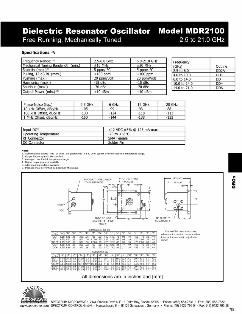
Dielectric Resonator Oscillator Free Running, Mechanically Tuned 2.5 to 21.0 GHz
Specifications (1):
Frequency Range: (2) 2.5-6.0 GHz 6.0-21.0 GHzMechanical Tuning Bandwidth (min.) ±10 MHz ±20 MHzStability (max.)(3) 5 ppm/ °C 5 ppm/ °CPulling, 12 dB RL (max.) ±100 ppm ±100 ppmPushing (max.) 20 ppm/Volt 20 ppm/VoltHarmonics (max.) -15 dBc -15 dBcSpurious (max.) -70 dBc -70 dBcOutput Power (min.) (4) +10 dBm +10 dBm
Model MDR2100
Input DC(5) +12 VDC ±3% @ 125 mA max.Operating Temperature -20 to +65°CRF Connector SMA FemaleDC Connector Solder Pin
Phase Noise (typ.) 2.5 GHz 6 GHz 12 GHz 20 GHz10 kHz Offset, dBc/Hz -105 -99 -93 -88100 kHz Offset, dBc/Hz -130 -124 -118 -1131 MHz Offset, dBc/Hz -150 -144 -138 -133
Frequency(GHz) Outline2.5 to 6.0 DD2A4.0 to 10.0 DD16.0 to 14.0 DD10.0 to 14.0 DD414.0 to 21.0 DD6
Notes:1. Specifications labeled “min.” or “max.” are guaranteed in a 50 Ohm system over the specified temperature range.2. Output frequency must be specified.3. Averaged over the full temperature range.4. Higher output power is available.5. Alternate input voltage available. 6. Package must be verified by Spectrum Microwave.
"J" DIA. THRU
"DD6" 41.9 18.4434.2937.1 3.8 9.1 25.48.1 3.6 21.1
"DD1""DD2A""DD4"
DIM.
"DD"OUTLINE
41.9
41.944.544.5
"A"
"DD6"
DIM.
"DD4""DD2A""DD1""DD"OUTLINE
1.65
1.751.65
"A"
1.651.75
VDC
GND
.726
DIMENSIONS: MM
DIMENSIONS: INCHES
19.0525.4025.4018.44"F"
"F"
.7261.0001.000.750
1.350
34.2938.1038.1034.29
1.3501.5001.5001.350
37.140.650.830.0
"B"3.8
3.83.03.0
"C"
1.461.182.001.601.46
"B"
.15
.15
.12
"C"
.15
.12
5.612.77.69.1"E""D"
.36
"E"
.36
.30
.50
.22
"D"
1.00
25.431.831.825.4"H"
"H"
1.001.251.251.00
8.16.46.48.1"G"
.32
"G"
.32
.25
.25
.32
3.6
3.23.23.2
"J"19.3
21.321.121.1
"K"
.140
.125
.125
"J"
.140
.125
.83
.83
.84
"K"
.76
.83
"D"
FREQ ADJUSTCOARSE
"A"
FINE
THIS SURFACEPRODUCT LABEL AREA
"C" MAX"S"
39.44.018.0 43.2 9.7 10.2
"N" MAX
"P" MAX
"G"
"H"
1.55
39.444.543.239.4"N"
"N"
1.551.701.751.55
4.84.84.84.0"M"
23.4
19.624.424.9
"L"
.16
"M"
.16
.19
.19
.19.96.77.71
"L"
.92
.98
43.250.850.843.2"P"
9.79.79.79.7
"R"
1.70
"P"
1.702.002.001.70
.38
.38
.38
.38
.38
"R"
"B" "R"
10.210.210.210.2
"S"
.40
.40
.40
.40
.40
"S"
SMA-FEMALERF OUTPUT
4 PLACES
"F" "E"
"K"
"L"
"M"
Note 1
1. Outline DD4 uses a separateadjustment screw for coarse and finetune vs. the concentric adjustmentshown.
All dimensions are in inches and [mm].
SPECTRUM MICROWAVE • 2144 Franklin Drive N.E. • Palm Bay, Florida 32905 • Phone: (888) 553-7531 • Fax: (888) 553-7532 SPECTRUM CONTROL GmbH • Hansastrasse 6 • 91126 Schwabach, Germany • Phone: (49)-9122-795-0 • Fax: (49)-9122-795-58
784
MICROWAVEA Spectrum Control Business
SPECTRUM
INC
.
www.specwave.com
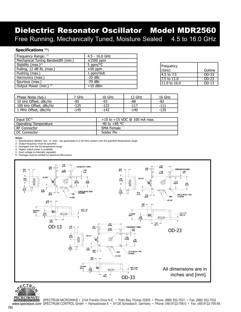
OD-13OD-23
OD-33
All dimensions are ininches and [mm].
Dielectric Resonator Oscillator Free Running, Mechanically Tuned, Moisture Sealed
Notes:1. Specifications labeled “min.” or “max.” are guaranteed in a 50 Ohm system over the specified temperature range.2. Output frequency must be specified.3. Averaged over the full temperature range.4. Higher output power is available.5. Input voltage is internally regulated. 6. Package must be verified by Spectrum Microwave.
Specifications (1):Frequency Range: (2) 4.5 - 16.0 GHzMechanical Tuning Bandwidth (min.) ±1500 ppmStability (max.)(3) 5 ppm/°CPulling, 12 dB RL (max.) ±50 ppmPushing (max.) 1 ppm/VoltHarmonics (max.) -20 dBcSpurious (max.) -70 dBcOutput Power (min.) (4) +10 dBm
Model MDR2560 4.5 to 16.0 GHz
Input DC(5) +10 to +15 VDC @ 100 mA max.Operating Temperature -40 to +85 °CRF Connector SMA FemaleDC Connector Solder Pin
Phase Noise (typ.) 7 GHz 10 GHz 12 GHz 16 GHz10 kHz Offset, dBc/Hz -95 -93 -88 -82100 kHz Offset, dBc/Hz -125 -122 -117 -1111 MHz Offset, dBc/Hz -145 -142 -140 -135
Frequency(GHz) Outline4.5 to 7.5 OD-337.5 to 11.0 OD-2311.0 to 16.0 OD-13
785
SPECTRUM MICROWAVE • 2144 Franklin Drive N.E. • Palm Bay, Florida 32905 • Phone: (888) 553-7531 • Fax: (888) 553-7532 SPECTRUM CONTROL GmbH • Hansastrasse 6 • 91126 Schwabach, Germany • Phone: (49)-9122-795-0 • Fax: (49)-9122-795-58
DR
Os
MICROWAVEA Spectrum Control Business
SPE
CTRUM
INC
.
www.specwave.com
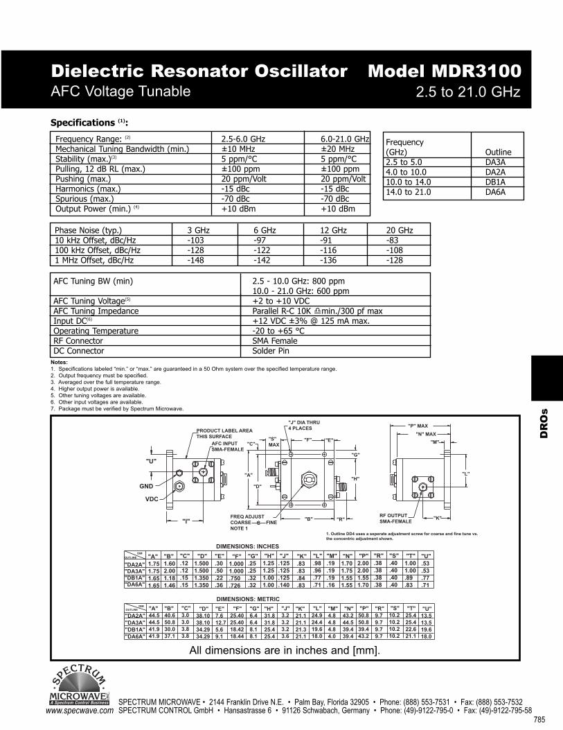
Dielectric Resonator OscillatorAFC Voltage Tunable 2.5 to 21.0 GHz
Notes:1. Specifications labeled “min.” or “max.” are guaranteed in a 50 Ohm system over the specified temperature range.2. Output frequency must be specified.3. Averaged over the full temperature range.4. Higher output power is available.5. Other tuning voltages are available.6. Other input voltages are available.7. Package must be verified by Spectrum Microwave.
Specifications (1):
Frequency Range: (2) 2.5-6.0 GHz 6.0-21.0 GHzMechanical Tuning Bandwidth (min.) ±10 MHz ±20 MHzStability (max.)(3) 5 ppm/°C 5 ppm/°CPulling, 12 dB RL (max.) ±100 ppm ±100 ppmPushing (max.) 20 ppm/Volt 20 ppm/VoltHarmonics (max.) -15 dBc -15 dBcSpurious (max.) -70 dBc -70 dBcOutput Power (min.) (4) +10 dBm +10 dBm
Model MDR3100
AFC Tuning BW (min) 2.5 - 10.0 GHz: 800 ppm10.0 - 21.0 GHz: 600 ppm
AFC Tuning Voltage(5) +2 to +10 VDCAFC Tuning Impedance Parallel R-C 10K �min./300 pf maxInput DC(6) +12 VDC ±3% @ 125 mA max.Operating Temperature -20 to +65 °CRF Connector SMA FemaleDC Connector Solder Pin
Phase Noise (typ.) 3 GHz 6 GHz 12 GHz 20 GHz10 kHz Offset, dBc/Hz -103 -97 -91 -83100 kHz Offset, dBc/Hz -128 -122 -116 -1081 MHz Offset, dBc/Hz -148 -142 -136 -128
Frequency(GHz) Outline2.5 to 5.0 DA3A4.0 to 10.0 DA2A10.0 to 14.0 DB1A14.0 to 21.0 DA6A
"U"
GND
VDC
"I"
PRODUCT LABEL AREATHIS SURFACE
AFC INPUTSMA-FEMALE
"A"
"D"
"C""S"MAX
"J" DIA THRU4 PLACES
"F" "E"
"G"
"H"
"R""B"FREQ ADJUSTCOARSE FINENOTE 1
"K"RF OUTPUTSMA-FEMALE
"L"
"M"
"N" MAX
"P" MAX
1. Outline DD4 uses a seperate adjustment screw for coarse and fine tune vs.the concentric adjustment shown.
"DA2A""DA3A""DB1A""DA6A"
"A"1.75 1.75 1.65 1.65
"B"1.60 2.00 1.18 1.46
"C".12 .12 .15 .15
"D"1.500 1.500 1.350 1.350
"E".30 .50 .22 .36
"F"1.000 1.000 .750 .726
"G".25 .25 .32 .32
"H"1.25 1.25 1.00 1.00
"J".125 .125 .125 .140
"K".83 .83 .84 .83
"L".98 .96 .77 .71
"M".19 .19 .19 .16
"N"1.70 1.75 1.55 1.55
"P"2.00 2.00 1.55 1.70
"R".38 .38 .38 .38
"S".40 .40 .40 .40
"T"1.00 1.00 .89 .83
"U".53 .53 .77 .71
DIMENSIONS: INCHES
DIMENSIONS: METRIC
"DA2A""DA3A""DB1A""DA6A"
"A"44.5 44.5 41.9 41.9
"B"40.6 50.8 30.0 37.1
"C"3.0 3.0 3.8 3.8
"D"38.10 38.10 34.29 34.29
"E"7.6 12.7 5.6 9.1
"F"25.40 25.40 18.42 18.44
"G" 6.4 6.4 8.1 8.1
"H"31.8 31.8 25.4 25.4
"J"3.2 3.2 3.2 3.6
"K"21.1 21.1 21.3 21.1
"L"24.9 24.4 19.6 18.0
"M"4.8 4.8 4.8 4.0
"N"43.2 44.5 39.4 39.4
"P"50.8 50.8 39.4 43.2
"R"9.7 9.7 9.7 9.7
"S"10.2 10.2 10.2 10.2
"T"25.4 25.4 22.6 21.1
"U"13.5 13.5 19.6 18.0
OUTLINEDIM
OUTLINE
DIM
All dimensions are in inches and [mm].
SPECTRUM MICROWAVE • 2144 Franklin Drive N.E. • Palm Bay, Florida 32905 • Phone: (888) 553-7531 • Fax: (888) 553-7532 SPECTRUM CONTROL GmbH • Hansastrasse 6 • 91126 Schwabach, Germany • Phone: (49)-9122-795-0 • Fax: (49)-9122-795-58
786
MICROWAVEA Spectrum Control Business
SPECTRUM
INC
.
www.specwave.com
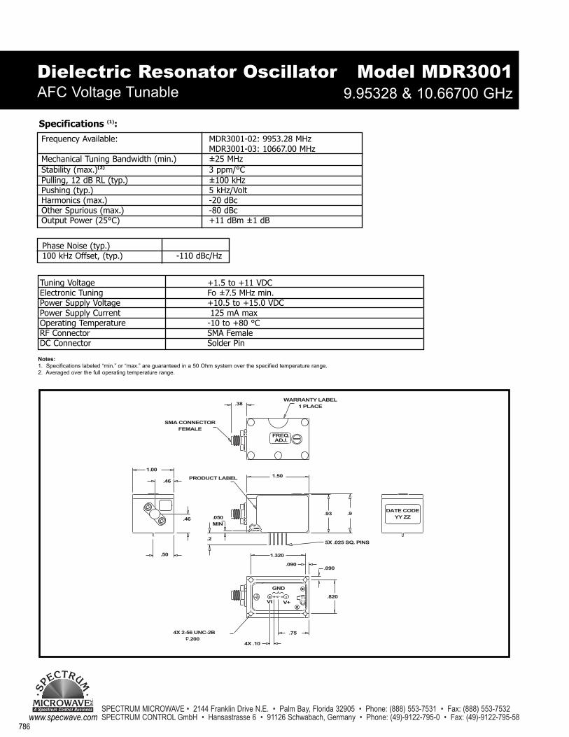
Dielectric Resonator Oscillator AFC Voltage Tunable
Notes:1. Specifications labeled “min.” or “max.” are guaranteed in a 50 Ohm system over the specified temperature range.2. Averaged over the full operating temperature range.
Specifications (1):Frequency Available: MDR3001-02: 9953.28 MHz
MDR3001-03: 10667.00 MHzMechanical Tuning Bandwidth (min.) ±25 MHzStability (max.)(2) 3 ppm/°C Pulling, 12 dB RL (typ.) ±100 kHz Pushing (typ.) 5 kHz/Volt Harmonics (max.) -20 dBcOther Spurious (max.) -80 dBcOutput Power (25°C) +11 dBm ±1 dB
Model MDR3001
Tuning Voltage +1.5 to +11 VDCElectronic Tuning Fo ±7.5 MHz min. Power Supply Voltage +10.5 to +15.0 VDCPower Supply Current 125 mA maxOperating Temperature -10 to +80 °CRF Connector SMA FemaleDC Connector Solder Pin
Phase Noise (typ.)100 kHz Offset, (typ.) -110 dBc/Hz
9.95328 & 10.66700 GHz
787
SPECTRUM MICROWAVE • 2144 Franklin Drive N.E. • Palm Bay, Florida 32905 • Phone: (888) 553-7531 • Fax: (888) 553-7532 SPECTRUM CONTROL GmbH • Hansastrasse 6 • 91126 Schwabach, Germany • Phone: (49)-9122-795-0 • Fax: (49)-9122-795-58
DR
Os
MICROWAVEA Spectrum Control Business
SPE
CTRUM
INC
.
www.specwave.com
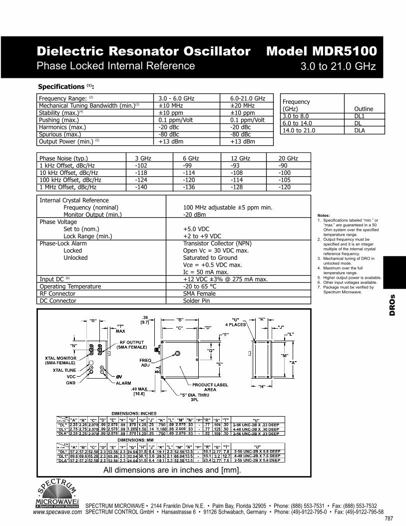
Phase Noise (typ.) 3 GHz 6 GHz 12 GHz 20 GHz1 kHz Offset, dBc/Hz -102 -99 -93 -9010 kHz Offset, dBc/Hz -118 -114 -108 -100100 kHz Offset, dBc/Hz -124 -120 -114 -1051 MHz Offset, dBc/Hz -140 -136 -128 -120
Dielectric Resonator OscillatorPhase Locked Internal Reference 3.0 to 21.0 GHz
Notes:1. Specifications labeled “min.” or
“max.” are guaranteed in a 50 Ohm system over the specified temperature range.
2. Output frequency must be specified and it is an integer multiple of the internal crystal reference frequency.
3. Mechanical tuning of DRO in unlocked mode.
4. Maximum over the full temperature range.
5. Higher output power is available.6. Other input voltages available. 7. Package must be verified by
Spectrum Microwave.
Specifications (1):
Frequency Range: (2) 3.0 - 6.0 GHz 6.0-21.0 GHzMechanical Tuning Bandwidth (min.)(3) ±10 MHz ±20 MHzStability (max.)(4) ±10 ppm ±10 ppmPushing (max.) 0.1 ppm/Volt 0.1 ppm/VoltHarmonics (max.) -20 dBc -20 dBcSpurious (max.) -80 dBc -80 dBcOutput Power (min.) (5) +13 dBm +13 dBm
Model MDR5100
Internal Crystal ReferenceFrequency (nominal) 100 MHz adjustable ±5 ppm min.Monitor Output (min.) -20 dBm
Phase VoltageSet to (nom.) +5.0 VDCLock Range (min.) +2 to +9 VDC
Phase-Lock Alarm Transistor Collector (NPN)Locked Open Vc = 30 VDC max.Unlocked Saturated to Ground
Vce = +0.5 VDC max.Ic = 50 mA max.
Input DC (6) +12 VDC ±3% @ 275 mA max.Operating Temperature -20 to 65 °CRF Connector SMA FemaleDC Connector Solder Pin
Frequency(GHz) Outline3.0 to 8.0 DL16.0 to 14.0 DL14.0 to 21.0 DLA
All dimensions are in inches and [mm].

SPECTRUM MICROWAVE • 2144 Franklin Drive N.E. • Palm Bay, Florida 32905 • Phone: (888) 553-7531 • Fax: (888) 553-7532 SPECTRUM CONTROL GmbH • Hansastrasse 6 • 91126 Schwabach, Germany • Phone: (49)-9122-795-0 • Fax: (49)-9122-795-58
788
MICROWAVEA Spectrum Control Business
SPECTRUM
INC
.
www.specwave.com
Dielectric Resonator OscillatorPhase Locked Internal Reference 9.0 to 13.0 GHz
Notes:1. Specifications labeled “min.” or “max.”
are guaranteed in a 50 Ohm system over the specified temperature range.
2. Exact output frequency must be specified.
Specifications (1):
Frequency Available: (2) 9.0 - 13.0 GHz CoverageStability (max.) ±2 ppm max.Harmonics (max.) -40 dBcSpurious (max.) -85 dBcOutput Power (min.) +17 dBm ±2dB
Model MDR5530
Internal Crystal ReferenceFrequency 100 MHz nominal
Phase VoltageSet to (nom.) +5.0 VDCLock Range (min.) +2 to +9 VDC
Phase-Lock Alarm TTL CompatibleLocked TTL HighUnlocked TTL LowInput DC +12 ±1 VDC @ 725 mA max. quiescent
1 A max. at cold startOperating Temperature -40 to +85°CRF Connector SMA MaleDC Connector Solder Pin
Phase Noise (typ.)100 Hz Offset -70 dBc/Hz max.1 kHz Offset -95 dBc/Hz max10 kHz Offset -105 dBc/Hz max100 kHz Offset -110 dBc/Hz max1 MHz Offset -130 dBc/Hz max
SPECTRUM
789
SPECTRUM MICROWAVE • 2144 Franklin Drive N.E. • Palm Bay, Florida 32905 • Phone: (888) 553-7531 • Fax: (888) 553-7532 SPECTRUM CONTROL GmbH • Hansastrasse 6 • 91126 Schwabach, Germany • Phone: (49)-9122-795-0 • Fax: (49)-9122-795-58
DR
Os
MICROWAVEA Spectrum Control Business
SPE
CTRUM
INC
.
www.specwave.com
Frequency(GHz) Outline3.0 to 8.0 DL16.0 to 14.0 DL14.0 to 21.0 DLA
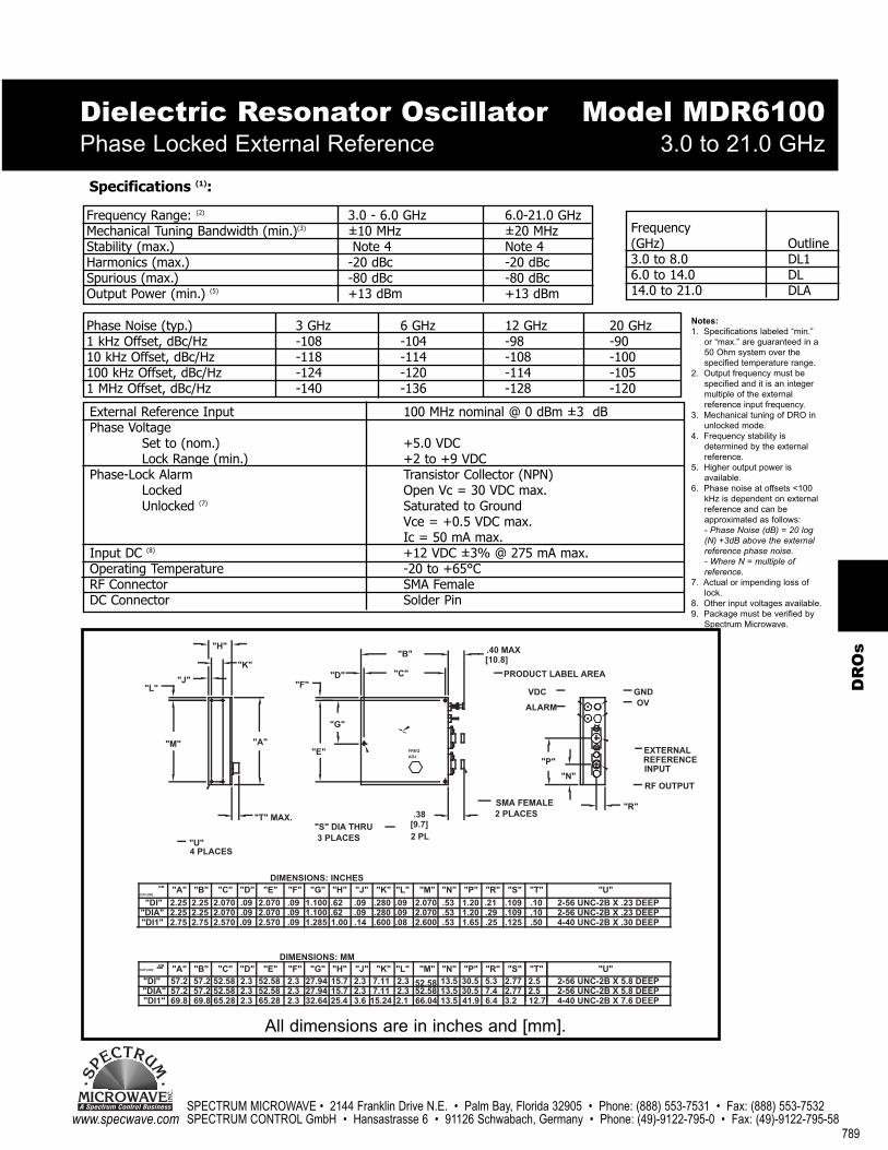
Dielectric Resonator Oscillator Phase Locked External Reference 3.0 to 21.0 GHz
Notes:1. Specifications labeled “min.”
or “max.” are guaranteed in a 50 Ohm system over the specified temperature range.
2. Output frequency must be specified and it is an integer multiple of the external reference input frequency.
3. Mechanical tuning of DRO in unlocked mode.
4. Frequency stability is determined by the external reference.
5. Higher output power is available.
6. Phase noise at offsets <100 kHz is dependent on external reference and can be approximated as follows:- Phase Noise (dB) = 20 log (N) +3dB above the external reference phase noise. - Where N = multiple of reference.
7. Actual or impending loss of lock.
8. Other input voltages available. 9. Package must be verified by
Spectrum Microwave.
Specifications (1):
Frequency Range: (2) 3.0 - 6.0 GHz 6.0-21.0 GHzMechanical Tuning Bandwidth (min.)(3) ±10 MHz ±20 MHzStability (max.) Note 4 Note 4Harmonics (max.) -20 dBc -20 dBcSpurious (max.) -80 dBc -80 dBcOutput Power (min.) (5) +13 dBm +13 dBm
Model MDR6100
External Reference Input 100 MHz nominal @ 0 dBm ±3 dBPhase Voltage
Set to (nom.) +5.0 VDCLock Range (min.) +2 to +9 VDC
Phase-Lock Alarm Transistor Collector (NPN)Locked Open Vc = 30 VDC max.Unlocked (7) Saturated to Ground
Vce = +0.5 VDC max.Ic = 50 mA max.
Input DC (8) +12 VDC ±3% @ 275 mA max.Operating Temperature -20 to +65°CRF Connector SMA FemaleDC Connector Solder Pin
Phase Noise (typ.) 3 GHz 6 GHz 12 GHz 20 GHz1 kHz Offset, dBc/Hz -108 -104 -98 -9010 kHz Offset, dBc/Hz -118 -114 -108 -100100 kHz Offset, dBc/Hz -124 -120 -114 -1051 MHz Offset, dBc/Hz -140 -136 -128 -120
2.32.1
2.3"L"
.09
"B"
"C"
"L"
.09
.08
7.112.315.727.942.352.582.352.5857.257.2"DIA""DI1" 69.8 2.365.2869.8 65.282.3 25.432.64 3.6 15.24
"J"
2.25"DI"
DIM.OUTLINE
"DI"
"DIA""DI1"
57.2"A"
2.252.75
DIM.
OUTLINE"A"
"M"
"L"
2.3"F"
DIMENSIONS: MM
.09
"T" MAX.
DIMENSIONS: INCHES"F"
.09
.09
2.0702.25
52.58
2.0702.570
"B"57.2
2.252.75
"C"
4 PLACES
"B"
"U"
"C"
2.070.09
52.58"E"
2.0702.570
2.3"D"
.09.09
"E""D"
"A"
15.7"H"
3 PLACES
"H"
1.00
.621.100
27.94"G"
1.1001.285
.62
"G"
.280.09
2.3"J"
.09
.14
7.11"K"
.280
.600
"J" "K"
"S" DIA THRU
"E"
"G"
"K"
"H"
"F""D"
2.5 2-56 UNC-2B X 5.8 DEEP7.4 2.7730.513.552.584-40 UNC-2B X 7.6 DEEP13.566.04 41.9 6.4 3.2 12.7
2-56 UNC-2B X 5.8 DEEP"U"
2-56 UNC-2B X .23 DEEP
"U"
2-56 UNC-2B X .23 DEEP
4-40 UNC-2B X .30 DEEP
PRODUCT LABEL AREA
2 PLACESSMA FEMALE
2 PL
13.5"N"
.53
"N"
.53
.53
2.070
52.58
"M"
2.0702.600
"M"
.211.20
30.5"P"
1.201.65
"R"5.3
.29
.25
"P" "R"
[9.7].38
FREQ
ADJ
.10.109
"S"2.77
.109
.125
2.5"T"
.50
.10
"S" "T"
ALARM
"P"
"N"
.40 MAX[10.8]
VDC
EXTERNAL
RF OUTPUT
REFERENCEINPUT
"R"
GNDOV
All dimensions are in inches and [mm].

SPECTRUM MICROWAVE • 2144 Franklin Drive N.E. • Palm Bay, Florida 32905 • Phone: (888) 553-7531 • Fax: (888) 553-7532 SPECTRUM CONTROL GmbH • Hansastrasse 6 • 91126 Schwabach, Germany • Phone: (49)-9122-795-0 • Fax: (49)-9122-795-58
790
MICROWAVEA Spectrum Control Business
SPECTRUM
INC
.
www.specwave.com
DRO Application Notes
DRO Application Note D-104
Phase-Locked DRO CharacteristicsThe Spectrum Microwave line of Phase-locked Dielectric Resonator Oscillators consists of the following series:
MDR 5100 Series - Phase-locked DRO, Internal Crystal Reference.MDR 6100 Series - Phase-locked DRO, External Crystal Reference.
These low-cost microwave oscillators exhibit excellent frequency stability and phase noise characteristics. The most common application for these microwave sources is as local oscillators in microwave radios. Other applications include frequency synthesizers, satellite converters, BITE oscillators, and frequency multipliers. The following paragraphs review the general characteristics of these oscillators. For detailed specifications or specific requirements, please contact SpectrumMicrowave.
GeneralSpectrum Microwave’s line of phase-locked DROs cover 3.0-26 GHz with output power of +13 dBm at26 GHz. They consist of an electronically tuned DRO, phase-locked to a reference crystal oscillator viaa sampling phase detector and loop amplifier/filter. This technique maintains the excellent frequencystability of the crystal oscillator and low phase noise characteristics of the crystal oscillator/DRO combination. The MDR 5100 Series contains an internal crystal oscillator reference, whereas, the MDR6100 Series requires an external reference. The output frequency is an exact integral multiple of thereference frequency.
DescriptionFigure 1 shows a simplified block diagram of a phase-locked DRO. The sampling phase detectorcreates an error signal corresponding to any attempted phase difference between the DRO andthe nth harmonic of the reference. This error signal is fed through the loop amplifier/filter to theDRO voltage tuning port, where it corrects for the attempted phase error. This feedback processallows the DRO to maintain the phase (and frequency) stability of the reference to the limits ofthe phase lock loop gain/bandwidth.
Figure 1

791
SPECTRUM MICROWAVE • 2144 Franklin Drive N.E. • Palm Bay, Florida 32905 • Phone: (888) 553-7531 • Fax: (888) 553-7532 SPECTRUM CONTROL GmbH • Hansastrasse 6 • 91126 Schwabach, Germany • Phone: (49)-9122-795-0 • Fax: (49)-9122-795-58
DR
Os
MICROWAVEA Spectrum Control Business
SPE
CTRUM
INC
.
www.specwave.com
The correction voltage applied to the DRO tuning port is referred to as the Phase Voltage (OV) and isgenerally accessible for monitoring. Under ambient conditions, the DC level of the phase voltage is setto a specified voltage, nominally the center of the DRO tuning voltage range (Lock Range). As theDRO frequency attempts to drift due to temperature or aging, the phase voltage DC level will changeas the phase lock loop corrects for the attempted drift. The phase voltage DC level will also change(and is initially set) by mechanically tuning the DRO Frequency Adjust. It should be noted that as theDRO is mechanically tuned over its specified mechanical tuning range, it will phase lock to each harmonic of the reference as they appear within the lock range.
The phase lock loop circuitry contains a search function to help in achieving phase lock when DCpower is first applied to the unit. The search function will voltage tune the DRO over the full lockrange until phase-lock is achieved. If the DRO is mechanically tuned off frequency, or the referenceinput is removed, the DRO will continue to sweep (search) over the full voltage tuning range. TheLock Range of a phase-locked DRO is typically 10 VDC, corresponding to a nominal frequency changeof 1000 ppm.
Crystal Oscillator ReferenceThe MDR 5100 Series uses an internal crystal oscillator reference. The crystal used is a 5th overtone,AT-cut crystal at 100 MHz nominal frequency. Standard frequency stability is ±10 ppm over the -20 to+65°C operating temperature range. Higher stabilities of ±5 ppm are consistently achieved over -10to +65°C using temperature compensation on the crystal oscillator. Further improvement is possible byovenizing the crystal. A screwdriver adjustment (Xtal tune) is available for resetting the frequency tocorrect for crystal aging.
Phase Lock AlarmThe phase lock alarm is a lock limit alarm which indicates when the phase lock loop has lost, or isabout to lose phase lock. The phase-locked DROs typically provide an open transistor collector to thealarm output. Loss of lock (or impending loss of lock) is indicated by the transistor collector being saturated to ground. This alarm circuit, when used with an appropriate pull-up resistor, is compatiblewith TTL and CMOS, or can be used directly with an LED or other types of panel indicators.
DRO Application Notes
SPECTRUM MICROWAVE • 2144 Franklin Drive N.E. • Palm Bay, Florida 32905 • Phone: (888) 553-7531 • Fax: (888) 553-7532 SPECTRUM CONTROL GmbH • Hansastrasse 6 • 91126 Schwabach, Germany • Phone: (49)-9122-795-0 • Fax: (49)-9122-795-58
792
MICROWAVEA Spectrum Control Business
SPECTRUM
INC
.
www.specwave.com
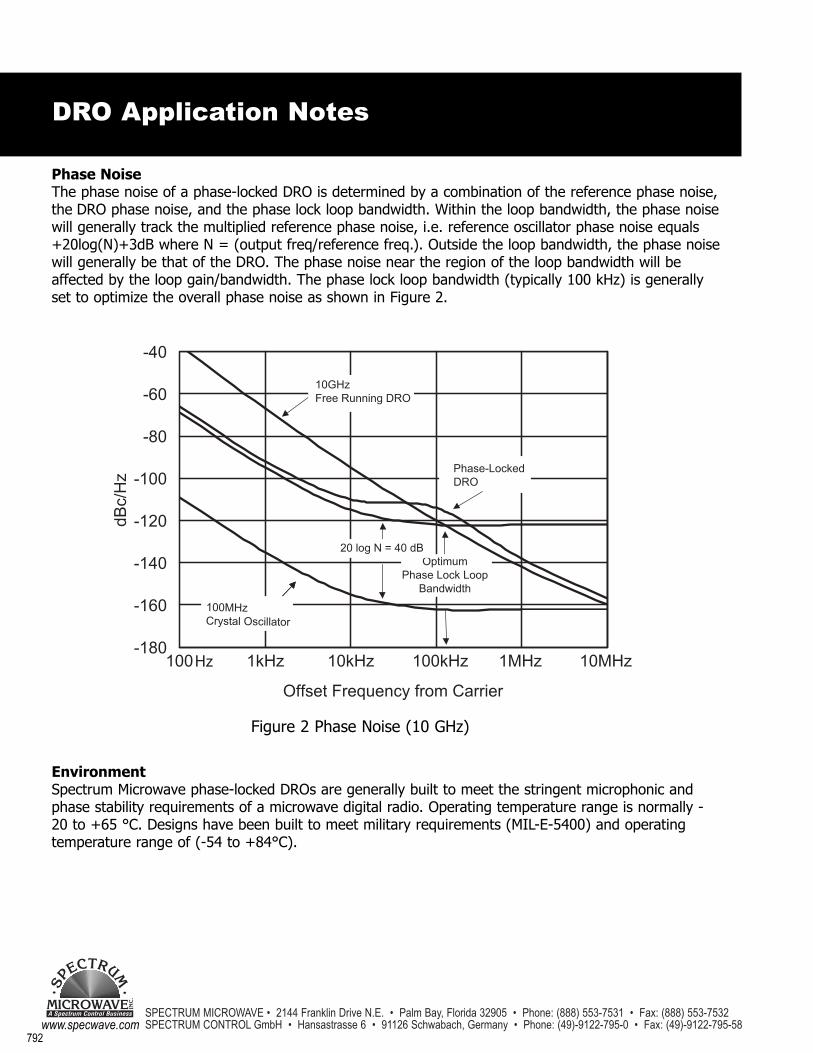
Phase NoiseThe phase noise of a phase-locked DRO is determined by a combination of the reference phase noise,the DRO phase noise, and the phase lock loop bandwidth. Within the loop bandwidth, the phase noisewill generally track the multiplied reference phase noise, i.e. reference oscillator phase noise equals+20log(N)+3dB where N = (output freq/reference freq.). Outside the loop bandwidth, the phase noisewill generally be that of the DRO. The phase noise near the region of the loop bandwidth will beaffected by the loop gain/bandwidth. The phase lock loop bandwidth (typically 100 kHz) is generallyset to optimize the overall phase noise as shown in Figure 2.
EnvironmentSpectrum Microwave phase-locked DROs are generally built to meet the stringent microphonic andphase stability requirements of a microwave digital radio. Operating temperature range is normally -20 to +65 °C. Designs have been built to meet military requirements (MIL-E-5400) and operatingtemperature range of (-54 to +84°C).
Figure 2 Phase Noise (10 GHz)
DRO Application Notes