P-Channel Power MOSFETs Selector Guide Power MOSFETs Selector Guide Vishay Siliconix 2201 Laurelwood...
20
P-Channel Power MOSFETs Selector Guide Vishay Siliconix 2201 Laurelwood Road P.O. Box 54951 Santa Clara, CA 95056 Phone: +1 408 988 8000 Fax: +1 408 567 8950 www.vishay.com
Transcript of P-Channel Power MOSFETs Selector Guide Power MOSFETs Selector Guide Vishay Siliconix 2201 Laurelwood...

P-Channel Power MOSFETsSelector Guide
Vishay Siliconix2201 Laurelwood Road
P.O. Box 54951
Santa Clara, CA 95056
Phone: +1 408 988 8000
Fax: +1 408 567 8950
www.vishay.com

NOTICE Specifications of the products displayed herein are subject to change without notice. Vishay Intertechnology, Inc., or anyone on its behalf, assumes no
responsibility or liability for any errors or inaccuracies. Information contained herein is intended to provide a product description only. No license, express or implied,
by estoppel or otherwise, to any intellectual property rights is granted by this document. Except as provided in Vishay’s terms and conditions of sale for such
products, Vishay assumes no liability whatsoever, and disclaims any express or implied warranty, relating to sale and/or use of Vishay products including liability
or warranties relating to fitness for a particular purpose, merchantability, or infringement of any patent, copyright, or other intellectual property right. The products
shown herein are not designed for use in medical, life-saving, or life-sustaining applications. Customers using or selling these products for use in such applications
do so at their own risk and agree to fully indemnify Vishay for any damages resulting from such improper use or sale.

Power MOSFETs Selector GuideVishay Siliconix
For technical support, contact [email protected]
www.vishay.com/mosfets�
Document Number: 70972Revision 08-�0-07
Vishay Siliconix leads the industry in the development of power MOS silicon and packaging technologies that boost power management, power conversion efficiency and greatly reducing the board area in computers, laptops, notebooks, PDAs, cellular phones, automotive electronics, consumer electronics, and many other systems.
Vishay Siliconix continually innovates to meet the increasing demands of applications such as dc-to-dc conversion and load switching. For example, our TrenchFET® Gen II power MOSFET silicon technology enables the first power MOSFETs in the SO-8 footprint with a maximum on-resistance of less than 4 milliohms at a 4.5-V gate drive. In another breakthrough, our WFET® power MOSFETs combine the ultra low on-resistance capabilities of TrenchFET
technology with extraordinarily low gate-drain capacitance to maximize dc-to-dc converter efficiency. A complete new family of p-channel power MOSFETs, built on a patent-pending TrenchFET technology, offers a reduction in on-resistance up to 45% compared with the previous state-of-the-art and signifies a new opportunity to reduce system power consumption.
Vishay Siliconix packaging innovations include the small-outline LITTLE FOOT, the thermally enhanced PowerPAK and PolarPAK, and the chipscale MICRO FOOT families, each of which provides designers with a range of surface-mount options to ensure efficient use of space in power management, power conversion, and other power MOSFET applications.
Vishay Siliconix Power MOSFETs – Compact and Efficient
Getting the Most Out of Your Selection and Design Process
This Selector Guide is organized by functionality, packaging (largest to smallest), breakdown voltage, and on-resistance (rDS(on) at 4.5 V). There is also an alphanumerically ordered listing with specifications. Although this Selector Guide is a convenient way to view the entire Vishay Siliconix Power MOSFET portfolio, we highly recommend that you visit our website, that is refreshed at least weekly, for the most up to date information.
Additionally, the power of the web allows us to enhance your selection and design-in process. Besides being able to click on the function, key specifications and size of MOSFET that you are looking for, there is also a parametric search engine. Either will give you a list of possible datasheets
integrated with a table of key specifications. From here you can click on any of the datasheets and “bundle” it with the related documents and drawings that you will need such as package, tape and reel and pad drawings, SPICE models, reliability information, and part marking.
Other web information includes application notes, a list of technical papers, and Selector Guides. Further, samples can be ordered and technical questions can be asked through the website.
Please take the time to review our web features on page 10, and visit http://www.vishay.com/mosfets.
Learn more about http:www.vishay.com/mosfets on page 10
Note: TrenchFET WFET are registered trademarks of Siliconix incorporated.
Introduction

Power MOSFETs Selector GuideVishay Siliconix
For technical support, contact [email protected]
Document Number: 70972Revision 08-�0-07
www.vishay.com/mosfets4
Next-Generation P-Channel TrenchFET®
Power MOSFETs Offer Industry-Low On-Resistance in Tiny Footprints to Extend Battery Life • Industry-low on-resistance in compact footprints
•Down to 29 milliohms in the PowerPAK SC-70 package (2.05 mm by 2.05 mm)
•Down to 80 milliohms in the standard SC-70 (2 mm by 2.1 mm)
•Down to 1�0 milliohms in the SC-89 (1.6 mm by 1.6 mm).
• -12-V, -20-V, and -�0-V devices available
Built on a new-generation TrenchFET® silicon technology, specifications for these p-channel devices represent an improvement of up to 6� % when compared to the next-best power MOSFETs on the market. The new p-channel TrenchFETs will be used for load switching, PA switching, and battery switching in portable end products including cell phones, MP� players, PDAs, and digital still cameras, where their low conduction losses will help to extend battery run times and their miniaturized packages will help to save valuable board space, allowing increased functionality. Siliconix was the first manufacturer to supply TrenchFET power MOSFETs, and with these new-generation devices reaffirms its leadership in Trench and p-channel power MOSFET technology.
The next-generation p-channel TrenchFET power MOSFETs include the Si1065X, Si1067X, Si1071X, and Si107�X in the SC-89 package; the Si1469DH, Si1471DH, and Si147�DH in the SC-70 package; and the SiA41�DJ and SiA421DJ in the PowerPAK SC-70. For latest devices in this family, visit the p-channel MOSFET gateway page www.vishay.com/mosfets/p-channel.
PowerPAK ChipFET Power MOSFETs Replace P-Channel TSOP-6 and N-Channel SO-8 Devices with Lower Thermal Resistance and Smaller FootprintVisit http://www.vishay.com/mosfets/powerpack-chipfet-package for the most updated list of devices
•Advanced thermal performance in a compact �-mm by 1.8-mm footprint
•�-W maximum power dissipation for high thermal efficiency
•Available in single, dual, co-packaged n- and p-channel and MOSFET + Schottky versions
•Breakdown voltage ratings from 8 V to 20 V
PowerPAK ChipFET provides a smaller-footprint alternative to MOSFETs in the TSOP-6 and SO-8 packages.
Compared to devices in the TSOP-6, new PowerPAK ChipFETs feature 75 % lower thermal resistance values, a �� % smaller footprint area, and a 25 % thinner height profile (0.8 mm). Enabling longer on-times in portable devices, p-channel PowerPAK ChipFETs will be used to replace load, PA, charger, and battery MOSFET switches in the TSOP-6.
The �-W maximum power dissipation of the PowerPAK ChipFET package is actually the same as the much larger SO-8, allowing n-channel PowerPAK ChipFETs to replace SO-8 MOSFETs in certain point-of load, fixed telecom synchronous rectification, and low-power computer dc-to-dc conversion applications. Additionally, the p-channel plus Schottky diode version will be used in asynchronous dc-to-dc applications, such as those found in hard disk drives and game consoles, to replace devices in the SO-8.
With their low conduction losses and enhanced thermal efficiency, power MOSFETs in Vishay’s new PowerPAK ChipFET family are pin-compatible with products in the standard ChipFET package.
PowerPAK ChipFET MOSFETs can be identified with Si5xxxDU part numbers.

Power MOSFETs Selector GuideVishay Siliconix
For technical support, contact [email protected]
www.vishay.com/mosfets5
Document Number: 70972Revision 08-�0-07
TrenchFET WFET are registered trademarks of Siliconix incorporated.
Breakthrough PolarPAK Package Brings High Reliability to Double-Sided CoolingVisit http://www.vishay.com/ref/polarpak-package for the most updated list of devices
• Dual thermal paths
– Top (1 °C/W) and bottom (1 °C/W) cooling provides dual heat dissipation paths for forced air applications – Double the current density (>60 A) of the SO-8 in same footprint area for space and cost savings
• Leadframe-based surface-mount packaging
– Easy handling enables high assembly yield – Plastic encapsulation provides good die protection and reliability – Fixed footprint and pad layout, independent of die size, across range of family
PolarPAK is the first power MOSFET package to combine double-sided cooling with an industry-standard leadframe and plastic encapsulation construction. Easy handling and mounting onto the PCB provides high assembly yields in mass-volume production. With multiple sources available, PolarPAK is well on its way to becoming an industry standard.
PolarPAK devices can be identified with the SiExxx prefix.
Industry’s First Load Switches Designed for On-Resistance Ratings at 1.2 V and 1.5 V• Optimized for use with the low-voltage core ICs in portable electronic systems
•Allow the driver voltage to turn on the switch from a lower output voltage than 1.8 V, reducing the need for level shift circuitry
•Help reduce power consumption and increase battery life
•Offer choice of on-resistance and package options with footprints as small as 1.5 mm by 1.5 mm
To help minimize power consumption and increase battery life, many of the ASICs found in portable electronics systems are designed to operate at core supply voltages between 1.5 and 1.65 V. Until now, however, the lack of power MOSFETs with guaranteed turn-on operation below 1.8 V has made it difficult for designers to take advantage of these low core supply voltages without the use of level-shifting circuitry, which adds complexity while increasing power consumption.
Vishay addresses this problem with breakthrough power MOSFETs that work directly from 1.2-V and 1.5-V core supply voltages with on-resistance as low as 4� milliohms. With their low threshold voltage and guaranteed specifications at a 1.2-V or 1.5-V gate drive, the new devices eliminate the need for level-shifting circuitry and maximize the power-saving benefits of low operating voltages in battery-operated systems.
Vishay’s 1.2-V and 1.5-V MOSFET families include n-channel and p-channel devices in packages as small as SC-70 packages, as well as in the chipscale MICRO FOOT format. For device selection, see www.vishay.com/mosfets.

Power MOSFETs Selector GuideVishay Siliconix
For technical support, contact [email protected]
Document Number: 70972Revision 08-�0-07
www.vishay.com/mosfets6
New ThermaSim™ is First On-Line Thermal Simulation Tool to Use Finite Element Analysis Models for Increased Accuracy•Available on http://www.vishay.com/thermal-modelling with exhaustive library of
Vishay Siliconix MOSFET models
•Can include effects of other heat dissipating components
•Allows user to configure:
– Power dissipation profiles
– Heat sink size, material, and attachment method
– PCB size, layers, material, copper spreading, vias, etc.
– Component placements and solder quality
– System temperature and air flow
•Simulation results are emailed directly to the designer and can be downloaded into Excel.
Vishay’s new ThermaSim™ is a free tool that helps designers speed time to market by allowing detailed thermal simulations of Vishay Siliconix power MOSFETs to be performed before prototyping. Applicable to any power MOSFET application, ThermaSim will be especially useful in high-current, high-temperature applications such as automotive, fixed telecom, desktop and laptop computers, and industrial systems.
Simulation results are emailed directly to the designer and can be downloaded into Excel. Multiple results with varying product, package, or other input data can be merged within Excel to compare and examine trends. Thermal images are provided, and a MPEG video clip of the thermal image with transient simulation is also available. Simulations can be saved for modifications at a later date.
Combining Advanced Thermal Conductivity, Excellent Electrical Performance and Ultimate MiniaturizationVisit http://www.vishay.com/powerpak-sc70-package for the most updated list of devices Visit http://www.vishay.com/powerpak-sc75-package for the most updated list of devices
• PowerPAK SC-70 & PowerPAK SC-75 provide performances of bigger packages in smaller footprints
– 55% smaller than TSOP-6 with better thermal performance and similar on-resistance
•Footprint compatible to TSOP-6 and SC-70 (PowerPAK SC-70), SC-75 and SC-89 (PowerPAK SC-75)
•Better performance than existing small footprints
– Half the thermal impedance while more than half the on-resistance of the industry standard SC-70 and SC-75 – Higher current density, higher power dissipation, increased junction temperature
•Capable of larger die sizes
•Ultra-compact, leadless 2.0 mm x 2.1 mm (PowerPAK SC-70) and 1.6 mm x 1.6 mm (PowerPAK SC-75) outline and low 0.7 mm profile are ideal for space-constrained portable devices
•Single and dual configurations
•For load switches in portable devices such as mobile phones, notebooks and computers, PDAs, digital cameras, MP� players

Power MOSFETs Selector GuideVishay Siliconix
For technical support, contact [email protected]
www.vishay.com/mosfets7
Document Number: 70972Revision 08-�0-07
Check out http://www.vishay.com/mosfets:• New features
• More content
• Refreshed weekly
Overview of Website
Selectors and datasheets for latest products
Related drawings and documents
Parametric SearchOn-line datasheet search engine by user-customized parameters
Online Selector Guide
Additional selectors and datasheets for latest products

Power MOSFETs Selector GuideVishay Siliconix
For technical support, contact [email protected]
Document Number: 70972Revision 08-�0-07
www.vishay.com/mosfets8
Sample Datasheet List
Key parameters help you choose which datasheet to click on
button gives you option of “bundling” the datasheet with related documents into one pdf. Menus also available while hovering over button.

Power MOSFETs Selector GuideVishay Siliconix
For technical support, contact [email protected]
www.vishay.com/mosfets9
Document Number: 70972Revision 08-�0-07
Order samples
One PDF with all documents
Ask a technical question
Sample of Datasheet with Related Documents

Power MOSFETs Selector GuideVishay Siliconix
For technical support, contact [email protected]
Document Number: 70972Revision 08-�0-07
www.vishay.com/mosfets10
1. Select desired parameters
2. Go to list of datasheets with key specification table
Example of Parametric Search
Power MOSFETs Selector GuideVishay Siliconix
For technical support, contact [email protected]
www.vishay.com/mosfets11
Document Number: 70972Revision 08-�0-07
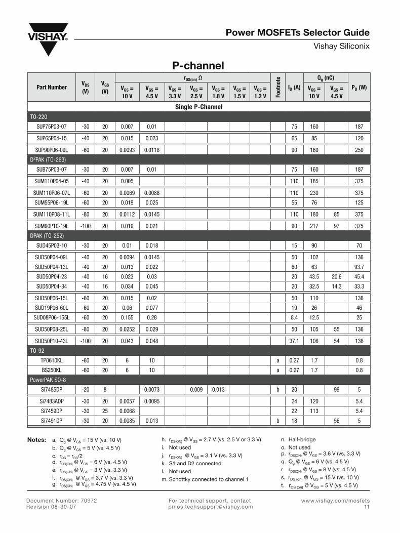
Notes: a. Qg @ VGS = 15 V (vs. 10 V)
b. Qg @ VGS = 5 V (vs. 4.5 V)
c. rDS = rSS/2 d. rDS(ON) @ VGS = 6 V (vs. 4.5 V)
e. rDS(ON) @ VGS = � V (vs. �.� V)
f. rDS(ON) @ VGS = �.7 V (vs. �.� V) g. rDS(ON) @ VGS = 4.75 V (vs. 4.5 V)
h. rDS(ON) @ VGS = 2.7 V (vs. 2.5 V or �.� V)
i. Not used
j. rDS(ON) @ VGS = �.1 V (vs. �.� V)
k. S1 and D2 connected
l. Not used
m. Schottky connected to channel 1
n. Half-bridge
o. Not used p. rDS(ON) @ VGS = �.6 V (vs. �.� V)
q. Qg @ VGS = 6 V (vs. 4.5 V)
r. rDS(ON) @ VGS = 8 V (vs. 4.5 V)
s. rDS (on) @ VGS = 15 V (vs. 10 V)
t. rDS (on) @ VGS = 5 V (vs. 4.5 V)
Part NumberVDS (V)
VGS (V)
rDS(on) Ω
Foot
note
ID (A)
Qg (nC)
PD (W)VGS = 10 V
VGS = 4.5 V
VGS = 3.3 V
VGS = 2.5 V
VGS = 1.8 V
VGS = 1.5 V
VGS = 1.2 V
VGS = 10 V
VGS = 4.5 V
Single P-ChannelTO-220
SUP75P03-07 -30 20 0.007 0.01 75 160 187
SUP65P04-15 -40 20 0.015 0.023 65 85 120
SUP90P06-09L -60 20 0.0093 0.0118 90 160 250
D2PAK (TO-263)
SUB75P03-07 -30 20 0.007 0.01 75 160 187
SUM110P04-05 -40 20 0.005 110 185 375
SUM110P06-07L -60 20 0.0069 0.0088 110 230 375
SUM55P06-19L -60 20 0.019 0.025 55 76 125
SUM110P08-11L -80 20 0.0112 0.0145 110 180 85 375
SUM90P10-19L -100 20 0.019 0.021 90 217 97 375
DPAK (TO-252)
SUD45P03-10 -30 20 0.01 0.018 15 90 70
SUD50P04-09L -40 20 0.0094 0.0145 50 102 136
SUD50P04-13L -40 20 0.013 0.022 60 63 93.7
SUD50P04-23 -40 16 0.023 0.03 20 43.5 20.6 45.4
SUD50P04-34 -40 16 0.034 0.045 20 32.5 14.3 33.3
SUD50P06-15L -60 20 0.015 0.02 50 110 136
SUD19P06-60L -60 20 0.06 0.077 19 26 46
SUD08P06-155L -60 20 0.155 0.28 8.4 12.5 25
SUD50P08-25L -80 20 0.0252 0.029 50 105 55 136
SUD50P10-43L -100 20 0.043 0.048 37.1 106 54 136
TO-92
TP0610KL -60 20 6 10 a 0.27 1.7 0.8
BS250KL -60 20 6 10 a 0.27 1.7 0.8
PowerPAK SO-8
Si7485DP -20 8 0.0073 0.009 0.013 b 20 99 5
Si7483ADP -30 20 0.0057 0.0095 24 120 5.4
Si7459DP -30 25 0.0068 22 113 5.4
Si7491DP -30 20 0.0085 0.013 b 18 56 5
P-channel

Power MOSFETs Selector GuideVishay Siliconix
For technical support, contact [email protected]
Document Number: 70972Revision 08-�0-07
www.vishay.com/mosfets12
Notes: a. Qg @ VGS = 15 V (vs. 10 V)
b. Qg @ VGS = 5 V (vs. 4.5 V)
c. rDS = rSS/2 d. rDS(ON) @ VGS = 6 V (vs. 4.5 V)
e. rDS(ON) @ VGS = � V (vs. �.� V)
f. rDS(ON) @ VGS = �.7 V (vs. �.� V) g. rDS(ON) @ VGS = 4.75 V (vs. 4.5 V)
h. rDS(ON) @ VGS = 2.7 V (vs. 2.5 V or �.� V)
i. Not used
j. rDS(ON) @ VGS = �.1 V (vs. �.� V)
k. S1 and D2 connected
l. Not used
m. Schottky connected to channel 1
n. Half-bridge
o. Not used p. rDS(ON) @ VGS = �.6 V (vs. �.� V)
q. Qg @ VGS = 6 V (vs. 4.5 V)
r. rDS(ON) @ VGS = 8 V (vs. 4.5 V)
s. rDS (on) @ VGS = 15 V (vs. 10 V)
t. rDS (on) @ VGS = 5 V (vs. 4.5 V)
P-channel, continued
Part NumberVDS (V)
VGS (V)
rDS(on) Ω
Foot
note
ID (A)
Qg (nC)
PD (W)VGS = 10 V
VGS = 4.5 V
VGS = 3.3 V
VGS = 2.5 V
VGS = 1.8 V
VGS = 1.5 V
VGS = 1.2 V
VGS = 10 V
VGS = 4.5 V
PowerPAK SO-8 (Continued)
Si7463DP -40 20 0.0092 0.014 18.6 121 5.4
Si7461DP -60 20 0.0145 0.019 14.4 121 5.4
Si7465DP -60 20 0.064 0.08 5 26 3.5
Si7469DP -80 20 0.025 0.029 28 105 55 83
Si7489DP -100 20 0.041 0.047 28 106 54 83
Si7439DP -150 20 0.09 0.095 d 5.2 88 5.4
Si7431DP -200 20 0.174 0.18 d 3.8 88 5.4
SO-8
Si4465ADY -8 8 0.009 0.011 0.016 13.7 55 3
Si4423DY -20 8 0.0075 0.009 0.0115 14 116 3
Si4421DY -20 8 0.00875 0.01075 0.0135 14 82 3
Si4463BDY -20 12 0.011 0.014 0.02 13.7 37 3
Si4403BDY -20 8 0.017 0.023 0.032 b 9.9 33 2.5
Si9424BDY -20 9 0.025 0.033 7.1 24 2
Si9433BDY -20 12 0.04 0.06 h 6.2 8.8 2.5
Si9434BDY -20 8 0.04 0.055 6.3 12 2.5
Si4803DY -20 12 0.065 0.105 5 9.7 4.5 3
Si4413ADY -30 20 0.0075 0.011 b 15 61 3
Si4427BDY -30 12 0.0105 0.0125 0.0195 12.6 47.2 2.5
Si4483EDY -30 25 0.0085 0.014 14 3
Si4425BDY -30 20 0.012 0.019 11.4 64 3
Si4825DY -30 25 0.014 0.022 11.5 55 3
Si4835BDY -30 25 0.018 0.03 b 9.6 25 2.5
Si4435BDY -30 20 0.02 0.035 9.1 33 2.5
Si4431BDY -30 20 0.03 0.05 7.5 11 2.5
Si9435BDY -30 20 0.042 0.07 d 5.7 16 2.5
Si4401BDY -40 20 0.014 0.021 b 10.5 40 2.9
Si4447DY -40 16 0.054 0.072 4.5 9 2
Si4409DY -150 20 1.2 1.3 d 1.3 7.7 4.8 4.6
TSSOP-8
Si6423DQ -12 8 0.0085 0.0106 0.014 b 9.5 74 1.5

Power MOSFETs Selector GuideVishay Siliconix
For technical support, contact [email protected]
www.vishay.com/mosfets1�
Document Number: 70972Revision 08-�0-07
Notes: a. Qg @ VGS = 15 V (vs. 10 V)
b. Qg @ VGS = 5 V (vs. 4.5 V)
c. rDS = rSS/2 d. rDS(ON) @ VGS = 6 V (vs. 4.5 V)
e. rDS(ON) @ VGS = � V (vs. �.� V)
f. rDS(ON) @ VGS = �.7 V (vs. �.� V) g. rDS(ON) @ VGS = 4.75 V (vs. 4.5 V)
h. rDS(ON) @ VGS = 2.7 V (vs. 2.5 V or �.� V)
i. Not used
j. rDS(ON) @ VGS = �.1 V (vs. �.� V)
k. S1 and D2 connected
l. Not used
m. Schottky connected to channel 1
n. Half-bridge
o. Not used p. rDS(ON) @ VGS = �.6 V (vs. �.� V)
q. Qg @ VGS = 6 V (vs. 4.5 V)
r. rDS(ON) @ VGS = 8 V (vs. 4.5 V)
s. rDS (on) @ VGS = 15 V (vs. 10 V)
t. rDS (on) @ VGS = 5 V (vs. 4.5 V)
P-channel, continued
Part NumberVDS (V)
VGS (V)
rDS(on) Ω
Foot
note
ID (A)
Qg (nC)
PD (W)VGS = 10 V
VGS = 4.5 V
VGS = 3.3 V
VGS = 2.5 V
VGS = 1.8 V
VGS = 1.5 V
VGS = 1.2 V
VGS = 10 V
VGS = 4.5 V
Si6467BDQ -12 8 0.0125 0.0155 0.02 8 46 1.5
Si6433BDQ -12 8 0.04 0.07 4.8 10 1.5
Si6463BDQ -20 8 0.015 0.02 0.027 7.4 40 1.5
Si6443DQ -30 20 0.012 0.019 8.8 38 1.5
Si6415DQ -30 20 0.019 0.03 6.5 47 1.5
Si6435ADQ -30 20 0.03 0.055 5.5 15 1.5
Si6459BDQ -60 20 0.115 0.15 2.7 14.5 1.5
PowerPAK 1212-8
Si7107DN -20 8 0.0108 0.015 0.02 15.3 34 3.8
Si7413DN -20 8 0.015 0.02 0.029 13.2 34 3.8
Si7411DN -20 8 0.019 0.025 0.034 11.4 27 3.6
Si7601DN -20 12 0.019 0.031 16 16.2 52
Si7403BDN -20 8 0.074 0.11 8 5.6 9.6
Si7409ADN -30 12 0.019 0.031 11 25 3.8
Si7423DN -30 20 0.018 0.03 11.7 37.5 3.8
Si7421DN -30 20 0.025 0.043 9.8 26.2 3.6
Si7415DN -60 20 0.065 0.11 5.7 15 3.8
Si7309DN -60 20 0.115 0.146 8 14.5 7.5 19.8
Si7113DN -100 20 0.113 0.145 13.2 35 16.5 52
Si7115DN -150 20 0.295 0.315 d 8.9 27.5 23.2 52
Si7117DN -150 20 1.2 1.3 d 2.17 7.7 12.5
Si7119DN -200 20 1.05 1.1 d 3.8 16.2 10.6 52
TSOP-6
Si3499DV -8 5 0.023 0.029 0.036 0.045 7 28 2
Si3473DV -12 8 0.023 0.029 0.041 7.9 22 2
Si3447BDV -12 8 0.04 0.053 0.072 6 9.3 2
Si3495DV -20 5 0.024 0.03 0.038 0.047 7 25 2
Si3493BDV -20 8 0.0275 0.034 0.045 8 26.2 2.97
Si3433BDV -20 8 0.042 0.057 0.08 5.6 12 2
Si3867DV -20 12 0.051 0.067 0.1 5.1 7 2
Si3469DV -20 20 0.03 0.051 6.7 20 2

Power MOSFETs Selector GuideVishay Siliconix
For technical support, contact [email protected]
Document Number: 70972Revision 08-�0-07
www.vishay.com/mosfets14
Notes: a. Qg @ VGS = 15 V (vs. 10 V)
b. Qg @ VGS = 5 V (vs. 4.5 V)
c. rDS = rSS/2 d. rDS(ON) @ VGS = 6 V (vs. 4.5 V)
e. rDS(ON) @ VGS = � V (vs. �.� V)
f. rDS(ON) @ VGS = �.7 V (vs. �.� V) g. rDS(ON) @ VGS = 4.75 V (vs. 4.5 V)
h. rDS(ON) @ VGS = 2.7 V (vs. 2.5 V or �.� V)
i. Not used
j. rDS(ON) @ VGS = �.1 V (vs. �.� V)
k. S1 and D2 connected
l. Not used
m. Schottky connected to channel 1
n. Half-bridge
o. Not used p. rDS(ON) @ VGS = �.6 V (vs. �.� V)
q. Qg @ VGS = 6 V (vs. 4.5 V)
r. rDS(ON) @ VGS = 8 V (vs. 4.5 V)
s. rDS (on) @ VGS = 15 V (vs. 10 V)
t. rDS (on) @ VGS = 5 V (vs. 4.5 V)
P-channel, continued
Part NumberVDS (V)
VGS (V)
rDS(on) Ω
Foot
note
ID (A)
Qg (nC)
PD (W)VGS = 10 V
VGS = 4.5 V
VGS = 3.3 V
VGS = 2.5 V
VGS = 1.8 V
VGS = 1.5 V
VGS = 1.2 V
VGS = 10 V
VGS = 4.5 V
TSOP-6 (Continued)
Si3443BDV -20 12 0.06 0.09 0.1 h 4.7 6 2
Si3441BDV -20 8 0.09 0.13 2.9 5.2 1.25
Si3467DV -20 20 0.054 0.094 5 8.7 2
Si3451DV -20 12 0.115 0.205 2.8 3.2 2.1
Si3465DV -20 20 0.08 0.17 b 4 3.5 2
Si3483DV -30 20 0.035 0.053 6.2 23 2
Si3481DV -30 20 0.048 0.079 5.3 15.5 2
Si3457BDV -30 20 0.054 0.1 5 12.5 2
Si3455ADV -30 20 0.1 0.17 3.5 8.5 2
Si3459DV -60 20 0.22 0.31 2.2 7 2
Si3437DV -150 20 0.75 0.79 d 1.4 12.2 8 3.2
Si3475DV -200 20 1.61 1.65 d 0.95 11.7 7.8 3.2
SOT-23
Si2305DS -8 8 0.052 0.071 0.108 3.5 10 1.25
Si2333DS -12 8 0.032 0.042 0.059 5.3 11.5 1.25
Si2315BDS -12 8 0.05 0.065 0.1 3.85 8 1.19
Si2323DS -20 8 0.039 0.052 0.068 4.7 12.5 1.25
Si2301BDS -20 8 0.1 0.15 2.4 4.5 0.9
Si2351DS -20 12 0.115 0.205 2.8 3.2 2.1
TP0101K -20 8 0.65 0.85 0.58 1.4 0.35
Si2343DS -30 20 0.053 0.086 4 14 1.25
Si2307BDS -30 20 0.078 0.13 3.2 9 1.25
Si2303BDS -30 20 0.2 0.38 1.64 4.3 0.9
TP0202K -30 1.4 3.5 0.385 1 0.35
Si2319DS -40 20 0.082 0.13 3 11.3 1.25
Si2309DS -60 20 0.34 0.55 1.25 5.4 1.25
TP0610K -60 20 5 10 0.4 1.2 0.25
Si2337DS -80 20 0.27 0.303 d, q 2.2 11 7 2.5
Si2325DS -150 20 1.2 1.3 d 0.69 7.7 1.25
Si2327DS -200 20 2.35 2.45 d 0.49 8 1.25

Power MOSFETs Selector GuideVishay Siliconix
For technical support, contact [email protected]
www.vishay.com/mosfets15
Document Number: 70972Revision 08-�0-07
Notes: a. Qg @ VGS = 15 V (vs. 10 V)
b. Qg @ VGS = 5 V (vs. 4.5 V)
c. rDS = rSS/2 d. rDS(ON) @ VGS = 6 V (vs. 4.5 V)
e. rDS(ON) @ VGS = � V (vs. �.� V)
f. rDS(ON) @ VGS = �.7 V (vs. �.� V) g. rDS(ON) @ VGS = 4.75 V (vs. 4.5 V)
h. rDS(ON) @ VGS = 2.7 V (vs. 2.5 V or �.� V)
i. Not used
j. rDS(ON) @ VGS = �.1 V (vs. �.� V)
k. S1 and D2 connected
l. Not used
m. Schottky connected to channel 1
n. Half-bridge
o. Not used p. rDS(ON) @ VGS = �.6 V (vs. �.� V)
q. Qg @ VGS = 6 V (vs. 4.5 V)
r. rDS(ON) @ VGS = 8 V (vs. 4.5 V)
s. rDS (on) @ VGS = 15 V (vs. 10 V)
t. rDS (on) @ VGS = 5 V (vs. 4.5 V)
P-channel, continued
Part NumberVDS (V)
VGS (V)
rDS(on) Ω
Foot
note
ID (A)
Qg (nC)
PD (W)VGS = 10 V
VGS = 4.5 V
VGS = 3.3 V
VGS = 2.5 V
VGS = 1.8 V
VGS = 1.5 V
VGS = 1.2 V
VGS = 10 V
VGS = 4.5 V
PowerPAK ChipFET
Si5481DU -20 8 0.022 0.029 0.041 12 20 17.8
Si5485DU -20 12 0.025 0.042 12 14 31
1206-8 ChipFET
Si5445BDC -8 8 0.033 0.043 0.06 7.1 14 2.5
Si5499DC -8 5 0.036 0.045 0.056 0.077 6 14 6.2
Si5473DC -12 8 0.027 0.0335 0.045 8.1 21 2.5
Si5401DC -20 8 0.032 0.04 0.053 7.1 16.5 2.5
Si5433BDC -20 8 0.037 0.05 0.07 6.7 15 2.5
Si5441BDC -20 12 0.045 0.052 0.08 6.1 11.5 2.5
Si5463EDC -20 12 0.062 0.085 0.12 5.1 9.7 2.3
Si5447DC -20 8 0.076 0.11 0.16 4.8 6.5 2.5
Si5435BDC -30 20 0.045 0.08 5.9 16 2.5
SC-70
Si1499DH -8 5 0.078 0.095 0.115 0.153 0.424 1.6 10.5 2.78
Si1305EDL -8 0.28 0.38 0.53 0.92 0.34
Si1305DL -8 8 0.28 0.38 0.53 0.92 2.6 0.34
Si1417EDH -12 12 0.085 0.115 0.16 3.3 5.8 1.56
Si1307EDL -12 8 0.29 0.435 0.58 0.91 3.2 0.34
Si1469DH -20 12 0.08 0.1 0.155 1.6 5.5 2.78
Si1413EDH -20 12 0.115 0.155 0.22 2.9 5.6 1.56
Si1403BDL -20 12 0.15 0.175 0.265 p 1.5 2.9 0.625
Si1303DL -20 12 0.43 0.48 0.7 0.72 1.7 0.34
Si1303EDL -20 12 0.43 0.48 0.7 0.72 0.34
Si1471DH -30 12 0.1 0.12 0.175 1.6 6.5 2.78
Si1473DH -30 20 0.1 0.145 1.6 4.1 2.78
Si1433DH -30 20 0.15 0.26 2.2 3.1 1.45
Si1411DH -150 20 2.6 2.7 d 0.52 4.2 1.56
Si1419DH -200 20 5 5.1 d 0.38 4.1 1.56
PowerPAK SC-70
SiA417DJ -8 5 0.023 0.031 0.04 0.058 0.095 12 19 19

Power MOSFETs Selector GuideVishay Siliconix
For technical support, contact [email protected]
Document Number: 70972Revision 08-�0-07
www.vishay.com/mosfets16
Notes: a. Qg @ VGS = 15 V (vs. 10 V)
b. Qg @ VGS = 5 V (vs. 4.5 V)
c. rDS = rSS/2 d. rDS(ON) @ VGS = 6 V (vs. 4.5 V)
e. rDS(ON) @ VGS = � V (vs. �.� V)
f. rDS(ON) @ VGS = �.7 V (vs. �.� V) g. rDS(ON) @ VGS = 4.75 V (vs. 4.5 V)
h. rDS(ON) @ VGS = 2.7 V (vs. 2.5 V or �.� V)
i. Not used
j. rDS(ON) @ VGS = �.1 V (vs. �.� V)
k. S1 and D2 connected
l. Not used
m. Schottky connected to channel 1
n. Half-bridge
o. Not used p. rDS(ON) @ VGS = �.6 V (vs. �.� V)
q. Qg @ VGS = 6 V (vs. 4.5 V)
r. rDS(ON) @ VGS = 8 V (vs. 4.5 V)
s. rDS (on) @ VGS = 15 V (vs. 10 V)
t. rDS (on) @ VGS = 5 V (vs. 4.5 V)
P-channel, continued
Part NumberVDS (V)
VGS (V)
rDS(on) Ω
Foot
note
ID (A)
Qg (nC)
PD (W)VGS = 10 V
VGS = 4.5 V
VGS = 3.3 V
VGS = 2.5 V
VGS = 1.8 V
VGS = 1.5 V
VGS = 1.2 V
VGS = 10 V
VGS = 4.5 V
PowerPAK SC-70 (Continued)
SiA413DJ -12 8 0.029 0.034 0.044 12 23 19
SiA419DJ -20 5 0.03 0.039 0.051 0.066 0.113 12 17.5 19
SiA411DJ -20 8 0.03 0.041 0.056 12 15 19
SiA443DJ -20 8 0.045 0.063 0.088 9 9 15
SiA421DJ -30 20 0.035 0.056 12 19 10 19
SC75A
Si1013R -20 1.2 1.6 2.7 0.37 1.5 0.25
Si1031R -20 8 12 15 0.14 1.5 0.25
Si1021R -60 5 10 a 0.17 1.7 0.25
PowerPAK SC-75
SiB417DK -8 5 0.052 0.07 0.093 0.13 0.222 9 7.78 13
SiB419DK -12 8 0.06 0.082 0.114 9 7.15 13.1
SiB411DK -20 8 0.066 0.094 0.13 9 6 13
SiB413DK -20 12 0.075 0.143 9 4.56 13
SiB415DK -30 20 0.087 0.158 9 6.7 3.5 13
SC89-6
Si1051X -8 5 0.122 0.141 0.168 0.198 1.2 5.91 0.236
Si1065X -12 8 0.13 0.158 0.205 1.18 6.7 0.236
Si1039X -12 8 0.165 0.22 0.28 0.95 3.8 0.21
Si1067X -20 8 0.15 0.166 0.214 1.06 6 0.236
Si1069X -20 12 0.184 0.268 0.94 4.23 0.236
Si1013X -20 1.2 1.6 2.7 0.4 1.5 0.3
Si1071X -30 12 0.167 0.188 0.244 0.96 8.87 4.43 0.236
Si1073X -30 20 0.173 0.243 0.98 6.3 3.25 0.236
MICRO FOOT
Si8429DB -8 5 0.035 0.042 0.052 0.069 0.098 11.7 21 6.25
Si8417DB -12 8 0.021 0.026 0.033 14.5 35 6.57
Si8415DB -12 8 0.037 0.046 0.06 7.3 19 2.77
Si8405DB -12 8 0.055 0.07 0.09 4.9 14 2.77
Si8407DB -20 8 0.027 0.032 0.045 8.2 32 2.9
Si8435DB -20 6 0.041 0.048 0.058 0.075 10 22 6.25

Power MOSFETs Selector GuideVishay Siliconix
For technical support, contact [email protected]
www.vishay.com/mosfets17
Document Number: 70972Revision 08-�0-07
Notes: a. Qg @ VGS = 15 V (vs. 10 V)
b. Qg @ VGS = 5 V (vs. 4.5 V)
c. rDS = rSS/2 d. rDS(ON) @ VGS = 6 V (vs. 4.5 V)
e. rDS(ON) @ VGS = � V (vs. �.� V)
f. rDS(ON) @ VGS = �.7 V (vs. �.� V) g. rDS(ON) @ VGS = 4.75 V (vs. 4.5 V)
h. rDS(ON) @ VGS = 2.7 V (vs. 2.5 V or �.� V)
i. Not used
j. rDS(ON) @ VGS = �.1 V (vs. �.� V)
k. S1 and D2 connected
l. Not used
m. Schottky connected to channel 1
n. Half-bridge
o. Not used p. rDS(ON) @ VGS = �.6 V (vs. �.� V)
q. Qg @ VGS = 6 V (vs. 4.5 V)
r. rDS(ON) @ VGS = 8 V (vs. 4.5 V)
s. rDS (on) @ VGS = 15 V (vs. 10 V)
t. rDS (on) @ VGS = 5 V (vs. 4.5 V)
P-channel, continued
Part NumberVDS (V)
VGS (V)
rDS(on) Ω
Foot
note
ID (A)
Qg (nC)
PD (W)VGS = 10 V
VGS = 4.5 V
VGS = 3.3 V
VGS = 2.5 V
VGS = 1.8 V
VGS = 1.5 V
VGS = 1.2 V
VGS = 10 V
VGS = 4.5 V
Si8413DB -20 12 0.048 0.063 6.5 14 2.77
Si8401DB -20 12 0.065 0.095 4.9 11 2.77
Si8409DB -30 12 0.046 0.065 6.3 17 2.77
Dual P-ChannelPowerPAK SO-8
Si7983DP -20 8 0.017 0.02 0.024 12 49 3.5
Si7945DP -30 20 0.02 0.031 10.9 49 3.5
Si7949DP -60 20 0.064 0.08 5 26 3.5
SO-8
Si4933DY -12 8 0.014 0.017 0.022 9.8 46 2
Si4931DY -12 8 0.018 0.022 0.028 8.9 34.5 2
Si9934BDY -12 8 0.035 0.056 6.4 13 2
Si4913DY -20 8 0.015 0.019 0.024 9.4 43 2
Si4943BDY -20 20 0.019 0.031 b 8.4 17 2
Si4963BDY -20 12 0.032 0.05 6.5 14 2
Si9933BDY -20 12 0.06 0.1 4.7 6 2
Si4973DY -30 25 0.023 0.029 d 7.6 37 2
Si4941EDY -30 20 0.021 0.031 10 46 26 3.6
Si4971DY -30 25 0.026 0.033 d 7.2 30 2
Si4925BDY -30 20 0.025 0.041 7.1 33 2
Si4953ADY -30 20 0.053 0.09 4.9 15 2
Si4947ADY -30 20 0.08 0.135 3.9 5.8 2
Si4948BEY -60 20 0.12 0.15 3.1 14.5 2.4
TSSOP-8
Si6913DQ -12 8 0.021 0.028 0.037 5.8 18.5 1.14
Si6969BDQ -12 8 0.03 0.04 0.055 4.6 16.5 1.14
Si6943BDQ -12 8 0.08 0.105 2.5 5.7 1.1
Si6983DQ -20 8 0.024 0.03 0.042 5.4 20 1.14
Si6981DQ -20 8 0.031 0.041 0.058 4.8 15 1.14
Si6963BDQ -20 12 0.045 0.08 3.9 8.6 1.13
Si6993DQ -30 20 0.031 0.048 4.7 13 1.14

Power MOSFETs Selector GuideVishay Siliconix
For technical support, contact [email protected]
Document Number: 70972Revision 08-�0-07
www.vishay.com/mosfets18
P-channel, continued
Part NumberVDS (V)
VGS (V)
rDS(on) Ω
Foot
note
ID (A)
Qg (nC)
PD (W)VGS = 10 V
VGS = 4.5 V
VGS = 3.3 V
VGS = 2.5 V
VGS = 1.8 V
VGS = 1.5 V
VGS = 1.2 V
VGS = 10 V
VGS = 4.5 V
PowerPAK 1212-8
Si7913DN -20 8 0.037 0.048 0.066 7.4 15.3 2.8
Si7911DN -20 8 0.051 0.067 0.094 5.7 9.5 2.5
Si7923DN -30 20 0.047 0.075 6.4 14 2.8
TSOP-6
Si3983DV -20 8 0.11 0.145 0.22 2.5 5 1.15
Si3951DV -20 12 0.115 0.205 2.7 3.2 2
Si3911DV -20 8 0.145 0.2 0.3 2.2 5 1.15
Si3981DV -20 8 0.185 0.26 0.385 1.9 3.2 1.08
Si3993DV -30 20 0.133 0.245 2.2 3.1 1.15
PowerPAK ChipFET
Si5943DU -12 8 0.064 0.089 0.12 6 6 8.3
Si5947DU -20 12 0.058 0.1 6 11 5.5 10.4
1206-8 ChipFET
Si5915BDC -8 8 0.07 0.086 0.145 4 5 3.1
Si5905BDC -8 8 0.08 0.117 0.17 4 4 3.1
Si5935DC -20 8 0.086 0.121 0.171 4.1 5.5 2.1
Si5933DC -20 8 0.11 0.16 0.24 3.6 5.1 2.1
Si5903DC -20 12 0.155 0.18 0.26 2.9 3 2.1
SC70
Si1917EDH -12 12 0.37 0.575 0.8 1.15 1.3 0.73
Si1913DH -20 8 0.49 0.75 1.1 1 1.2 0.74
Si1913EDH -20 12 0.49 0.75 1.1 1 1.2 0.74
Si1903DL -20 12 0.995 1.19 1.8 0.44 1.2 0.3
PowerPAK SC-70
SiA913DJ -12 8 0.07 0.1 0.14 4.5 5 6.5
SiA911DJ -20 8 0.094 0.131 0.185 4.5 4.9 6.5
SiA917DJ -20 12 0.11 0.185 4.5 6 3 6.5
SiB911DK -20 8 0.295 0.42 0.56 2.6 1.6 3.1
SC89-6
Si1023X -20 1.2 1.6 2.7 0.4 1.5 0.3
Si1033X -20 8 12 15 0.16 1.5 0.3
Si1025X -60 4 8 a 0.2 1.7 0.28
Notes: a. Qg @ VGS = 15 V (vs. 10 V)
b. Qg @ VGS = 5 V (vs. 4.5 V)
c. rDS = rSS/2 d. rDS(ON) @ VGS = 6 V (vs. 4.5 V)
e. rDS(ON) @ VGS = � V (vs. �.� V)
f. rDS(ON) @ VGS = �.7 V (vs. �.� V) g. rDS(ON) @ VGS = 4.75 V (vs. 4.5 V)
h. rDS(ON) @ VGS = 2.7 V (vs. 2.5 V or �.� V)
i. Not used
j. rDS(ON) @ VGS = �.1 V (vs. �.� V)
k. S1 and D2 connected
l. Not used
m. Schottky connected to channel 1
n. Half-bridge
o. Not used p. rDS(ON) @ VGS = �.6 V (vs. �.� V)
q. Qg @ VGS = 6 V (vs. 4.5 V)
r. rDS(ON) @ VGS = 8 V (vs. 4.5 V)
s. rDS (on) @ VGS = 15 V (vs. 10 V)
t. rDS (on) @ VGS = 5 V (vs. 4.5 V)

Power MOSFETs Selector GuideVishay Siliconix
For technical support, contact [email protected]
www.vishay.com/mosfets19
Document Number: 70972Revision 08-�0-07
Packaging Information
* To view drawings of any of the products above in PDF form, go to http://www.vishay.com/mosfets/related#pkgdrw
Power MOSFET Packages*Max
Length(mm)
Max Width(mm)
Max Footprint
Area (mm2)
Max Height(mm)
Max Current
(A)
Max Temp(°C)
RthJF or RthJC
(°C/W)
TO-220 10.41 4.7 48.93 29.71 85 175 0.6
TO-262 10.41 4.7 48.93 25.27 85 175 0.6
D2PAK15.88 10.41 165.37 4.83
110 175 0.4
85 175 0.6
D2PAK-5 60 175 0.5
DPAK 10.41 6.73 70.06 2.38 70 175 1.2
TO-92/T0-92S 4.7 3.68 17.30 19.94 0.67 150 1.2
PolarPAK 6.3 5.31 33.45 0.85 45 150 1.0 + 1.0
PowerPAK SO-8 6.2 5.26 32.61 1.2 29 150 1.5
SO-16 10 6.2 62.00 1.75 13.5 150 20
SO-8 5 6.2 31.00 1.75 25 150 16
TSSOP-8 3.1 6.6 20.46 1.2 11 150 52
PowerPAK 1212-8 3.4 3.4 11.56 1.2 14.4 150 2.4
PowerPAK 2 x 5 5.10 2.15 10.97 0.84 7 150 6
TSOP-6 3.1 2.98 9.24 1.1 6.8 150 30
PowerPAK ChipFET 3.08 1.98 6.10 0.85 11.6 150 4
ChipFET 1206-8 3.1 1.915 5.58 1.1 9.5 150 20
SOT-23 3.04 2.64 8.03 1.12 4.9 150 50
PowerPAK SC-70 2.15 2.15 4.62 0.8 12 150 6.5
SC-70 2.2 2.4 5.28 1.1 3.9 150 45

Power MOSFETs Selector GuideVishay Siliconix
For technical support, contact [email protected]
Document Number: 70972Revision 08-�0-07
www.vishay.com/mosfets20
* To view drawings of any of the products above in PDF form, go to http://www.vishay.com/mosfets/related#pkgdrw
Packaging Information, continued
Power MOSFET Packages*Max
Length(mm)
Max Width(mm)
Max Footprint
Area (mm2)
Max Height(mm)
Max Current
(A)
Max Temp(°C)
RthJF or RthJC
(°C/W)
MICRO FOOT See individual datasheet 0.65 7 150 20
PowerPAK SC-75 1.7 1.7 2.89 0.8 8 150 9.5
SC-75A 1.6 1.7 2.72 0.8 0.5 150
SC-89 1.7 1.7 2.89 0.6 0.5 150


![[06] Chapter06_Electrical Characteristic of MOSFETs](https://static.fdocuments.in/doc/165x107/55cf968e550346d0338c45ba/06-chapter06electrical-characteristic-of-mosfets.jpg)