P a t r i o t Wood Stove - Lopi · PDF file2 Introduction © Travis Industries 93508039...
34
Patriot Wood Stove Owner's Manual • Freestanding Stove • Mobile-Home Approved • Alcove Approved • Hearth-Stove Approved Save these instructions for future reference SAFETY NOTICE: If this appliance is not properly installed, a house fire may result. For your safety, follow the installation directions. Contact local building or fire officials about restrictions and installation inspection requirements in your area. Copyright 2006, T.I. $10.00 93508039 4040820 Listed Tested to: U.L. 1482
Transcript of P a t r i o t Wood Stove - Lopi · PDF file2 Introduction © Travis Industries 93508039...

P a t r i o t Wood StoveOwner's Manual
• Freestanding Stove
• Mobile-Home Approved
• Alcove Approved
• Hearth-Stove Approved
Save these instructions
for future reference
SAFETY NOTICE:If this appliance is not properly installed, a house fire mayresult. For your safety, follow the installation directions.Contact local building or fire officials about restrictions andinstallation inspection requirements in your area.
Copyright 2006, T.I.$10.00 93508039
4040820 Listed
Tested to: U.L. 1482

2 Introduction
© Travis Industries 93508039 4040820
IntroductionWe welcome you as a new owner of a Lopi Patriot wood-burning stove. In purchasing a Patriot you havejoined the growing ranks of concerned individuals whose selection of an energy system reflects both aconcern for the environment and aesthetics. The Patriot is one of the finest appliances the world over.This manual will explain the installation, operation, and maintenance of this appliance. Please familiarizeyourself with the Owner's Manual before operating your appliance and save the manual for futurereference. Included are helpful hints and suggestions which will make the installation and operation ofyour new appliance an easier and more enjoyable experience. We offer our continual support andguidance to help you achieve the maximum benefit and enjoyment from your appliance.
Important Information
No other Lopi Patriot appliance has the same serialnumber as yours. The serial number is stamped ontothe label on the back of the appliance.
This serial number will be needed in case you requireservice of any type.
Model: Lopi Patriot
Serial Number:
Purchase Date:
Purchased From:
Mail your Warranty Card Today, and Save Your Billof Sale.
To receive full warranty coverage, you will need toshow evidence of the date you purchased yourappliance. Do not mail your Bill of Sale to us.
We suggest that you attach your Bill of Sale to thispage so that you will have all the information you needin one place should the need for service or informationoccur.

Table of Contents 3
© Travis Industries 93508039 4040820
General Information
Introduction & Important Information...................... 2
Safety Precautions ............................................ 4
Features & Specifications.................................... 6
Stove Installation
Planning The Installation..................................... 7
Floor Protection Requirements ............................. 8
Stove Placement Requirements ........................... 8
Clearances ...................................................... 8
Chimney Requirements ...................................... 10
Chimney Termination Requirements...................... 11
Outside Air Requirements ................................... 11
Alcove Installation Requirements .......................... 12
Mobile Home Requirements ................................ 13
INSTALLATION DIAGRAMS
Standard Ceiling with a Factory Built Chimney......... 14
Cathedral Ceiling with a Factory Built Chimney........ 14
Exterior Factory Built Chimney ............................. 15
Hearth Stove Positive Connection......................... 15
Hearth Stove Direct Connection ........................... 16
Interior Masonry Chimney ................................... 16
Operating Your Appliance
Safety Notice.................................................... 17
Before Your First Fire ......................................... 17
Opening the Door .............................................. 17
Starting a Fire................................................... 18
Adjusting the Burn Rate ...................................... 19
Ash Removal.................................................... 19
Optional Blower Operation .................................. 20
Re-Loading the Stove......................................... 20
Overnight Burn ................................................. 20
Normal Operating Sounds ................................... 20
Hints for Burning ............................................... 21
Selecting Wood................................................. 21
Troubleshooting ................................................ 22
Maintaining Your Appliance
Daily Maintenance ............................................. 23
Remove Ash .................................................... 23
Clean The Glass ............................................... 23
Monthly Maintenance ......................................... 24
Door and Glass Inspection .................................. 24
Check For Creosote Buildup ................................ 24
Yearly Maintenance ........................................... 25
Touch Up Paint ................................................. 25
Blower Cleaning................................................ 25
Firebrick and Baffle Inspection ............................. 25
Door Parts ....................................................... 26
Replacing the Glass........................................... 26
Replacing the Door Gasket.................................. 26
Replacing the Door Handle.................................. 26
Firebox Parts.................................................... 27
Floor & Side Firebrick Removal & Replacement....... 27
Baffle Removal and Replacement ......................... 28
Air Tube Removal and Replacement ..................... 28
Warranty
Warranty ......................................................... 29
Listing Information
Listing Information ............................................. 30
Optional Equipment
Rear Blower Installation ...................................... 31
Outside Air Boot Installation................................. 32
Index
Index .............................................................. 34

4 Safety Precautions
© Travis Industries 93508039 4040820
The viewing door must beclosed and latched duringoperation.
Never block free airflow throughthe air vents on this appliance.
Gas
Gasoline or other flammableliquids must never be used tostart the fire or "Freshen Up" thefire. Do not store or usegasoline or other flammableliquids in the vicinity of thisappliance.
This appliance is designed andapproved for the burning of cordwood only. Do not attempt toburn any other type of fuel otherthan cord wood in thisappliance, it will void allwarranties and safety listings.
ASHES
Ashes must be disposed in ametal container with a tight lidand placed on a non-combustible surface well awayfrom the home or structure.
Do not touch the appliance whileit is hot and educate all childrenof the danger of a high-temperature appliance. Youngchildren should be supervisedwhen they are in the same roomas the appliance.
36"
Keep furniture, drapes, curtains,wood, paper, and othercombustibles a minimum of 36"away from the front of theappliance.
This appliance must be properlyinstalled to prevent thepossibility of a house fire. Theinstructions must be strictlyadhered to. Do not usemakeshift methods orcompromise in the installation.
Ok
Contact your local buildingofficials to obtain a permit andinformation on any installationrestrictions or inspectionrequirements in your area.Notify your insurance companyof this appliance as well.
Inspect the chimney connectorand chimney at least twicemonthly and clean if necessary.Creosote may build up andcause a house fire.
Do not connect this appliance toany chimney serving anotherappliance.
Type HT
Clay Liner
This appliance must beconnected to a listed hightemperature (UL 103 HT)residential type chimney or anapproved masonry chimney witha standard clay tile, or stainlesssteel liner.

Safety Precautions 5
© Travis Industries 93508039 4040820
MobileHome
When installed in a mobilehome, this appliance must bebolted to the floor, have outsideair, and not be installed in thebedroom (Per H.U.D.requirements). Check with localbuilding officials.
Do not place clothing or otherflammable items on or near thisappliance.
Never try to repair or replaceany part of this appliance unlessinstructions are given in thismanual. All other work must bedone by a trained technician.
Do not make any changes ormodifications to an existingmasonry fireplace or chimney toinstall this appliance.
Do not make any changes to theappliance to increasecombustion air.
AAAA Allow the appliance to cool
before carrying out anymaintenance or cleaning. Overfiring the appliance may
cause a house fire. If a unit orchimney connector glows, youare overfiring.
Maintain the door and glass sealand keep them in goodcondition.
Avoid placing wood against theglass when loading. Do notslam the door or strike the glass.
Do not use a grate or otherdevice to elevate the fire off ofthe firebox floor. Burn the firedirectly on the bricks.
ThisManual
Do not throw this manual away.This manual has importantoperating and maintenanceinstructions that you will need ata later time. Always follow theinstructions in this manual.
Travis Industries, Inc. grantsno warranty, implied orstated, for the installation ormaintenance of yourappliance, and assumes noresponsibility of anyconsequential damage(s).
6 Features & Specifications
© Travis Industries 93508039 4040820
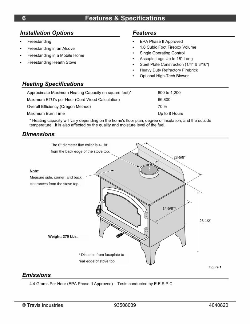
Installation Options• Freestanding
• Freestanding in an Alcove
• Freestanding in a Mobile Home
• Freestanding Hearth Stove
Features• EPA Phase II Approved• 1.6 Cubic Foot Firebox Volume• Single Operating Control• Accepts Logs Up to 18" Long• Steel Plate Construction (1/4" & 3/16")• Heavy Duty Refractory Firebrick• Optional High-Tech Blower
Heating SpecificationsApproximate Maximum Heating Capacity (in square feet)* 600 to 1,200
Maximum BTU's per Hour (Cord Wood Calculation) 66,800
Overall Efficiency (Oregon Method) 70 %
Maximum Burn Time Up to 8 Hours
* Heating capacity will vary depending on the home's floor plan, degree of insulation, and the outsidetemperature. It is also affected by the quality and moisture level of the fuel.
Dimensions
Note:
Measure side, corner, and back
clearances from the stove top.
The 6" diameter flue collar is 4-1/8"
from the back edge of the stove top.
23-5/8"
26-1/2"
14-5/8"*
* Distance from faceplate to
rear edge of stove top
Weight: 270 Lbs.
Figure 1
Emissions4.4 Grams Per Hour (EPA Phase II Approved) – Tests conducted by E.E.S.P.C.

Stove Installation (for qualified installers only) 7
© Travis Industries 93508039 4040820
SAFETY NOTICE:Please read this entire manual before you install and use your new room heater. Failureto follow instructions may result in property damage, bodily injury, or even death.Contact local building or fire officials about restrictions and installation inspectionrequirements in your area.
Planning The InstallationWe suggest that you have an authorized Travis Industries dealer install your stove. If you install thestove yourself, your authorized dealer should review your installation plans.
Check with local building officials for any permits required for installation of this stove and notify yourinsurance company before proceeding with installation.
Preparation for Installation
• Check for damage to the exterior of the stove (dents should be reported, scratches can be fixed byapplying touch up paint).
• Check the interior of the firebox (replace cracked firebrick and make sure baffle is in place).
The stove can be lightened by removing the firebricks and baffle (pg 27) - replace before operation.
Stove Leg Installation
Raise the stove 8" (use lumber) and attach the included legs following the directions in Figure 2.
Attach each leg to the stove by inserting a bolt and washer through the hole or slot in the leg and into the threaded hole on the stove.
9/16" Socket WrenchThese rubber-tipped bolts are for leveling the stove. Make sure they contact the floor. Do not adjust with weight on the legs, the rubber tips may tear.
Figure 2
Pipe Heat Shield Installation
Install the pipe heat shield following thedirections in Figure 3.
The pipe heat shield is
shipped inside the
stove. Install it by
sliding this joggle over
the back heat shield.
Figure 3

8 Stove Installation (for qualified installers only)
© Travis Industries 93508039 4040820
Floor Protection Requirements• Floor protection must extend 6" to the sides and rear of the stove and 16" to the front of the stove
(35-5/8" wide by 36-5/8" deep - see Figure 4 and Figure 5).
• Floor protection must be non-combustible and at least .018" thick (26 guage).
Stove Placement RequirementsClearances may be reduced by methods specified in NFPA 211, listed wall shields, pipe shields, orother means approved by local building or fire officials.
• Stove must be placed so that no combustibles are within, or can swing within (e.g. drapes, doors), 36"of the front of the stove
• If the stove is placed in a location where the ceiling height is less than 7', it must follow therequirements in the section "Alcove Installation Requirements"
• Must maintain the clearances to combustibles listed below (drywall, furniture, etc.):
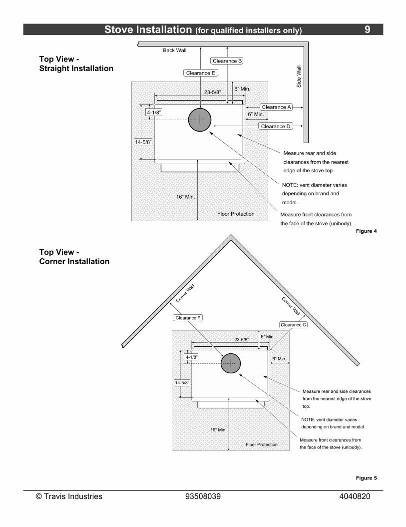
Clearances• The following clearances must be met (see Figure 4 and Figure 5)
Minimum Clearance Singlewall Connector Reduced Clearance*
A Sidewall to stove 18" 18"
B Backwall to stove 18” 10-1/2"
C Cornerwall to stove 10" 10"
D Connector to sidewall 27" 26-1/2"
E Connector to backwall 19-1/4" 11-1/4"
F Connector to cornerwall 17-3/4" 17-1/4"
*Reduced clearance installations require one of the chimneys and connectors listed below:AMERI-TEC model DCC with model HS chimneyDURAVENT model DVL with DURATEC or DURA-PLUS chimneyGSW Super Chimney Twenty-One connected directly to applianceI.C.C. Excel (2100-2 Can.) (103-HT USA) chimney with HP connectorMETALFAB model DW connector with TG chimneyOLIVER MACLEOD PROVENT model PV connector with model 3103 chimneySECURITY model DP connector with SECURITY model ASHT or S2100 chimneySELKIRK METALBESTOS model DS connector with model SSII chimneyStandard Masonry Chimney with any one of the above listed connectorsNOTE: Reduced clearance connectors may not connect to the flue collar – an appliance adapter may be required.
NOTE: Standard residential installations with reduced clearance connector may use the clearancedetermined by the manufacturer of the connector for the connector to wall clearance or the clearancelisted in this manual. Offsets must be used to maintain the stove to wall clearance.
Stove Installation (for qualified installers only) 9
© Travis Industries 93508039 4040820
Top View -Straight Installation
AAAAAAAAAAAAAAAAAAAAAAAAAAAAAAAAAAAAAAAAAAAAAAAAAAAAAAAAAAAAAAAAAAAAAAAAAAAAAAAAAAAAAAAAAAAAAAAAAAAAAAAAAAAAAAAAAAAAAAAAA
Measure rear and side
clearances from the nearest
edge of the stove top.
Floor Protection
23-5/8”
14-5/8”
16” Min.
Measure front clearances from
the face of the stove (unibody).
6” Min.
6” Min.
Clearance A
NOTE: vent diameter varies
depending on brand and
model.
Clearance D
Clearance E
Clearance B
Back Wall
Sid
e W
all
4-1/8”
Figure 4
Top View -Corner Installation
AAAAAAAAAAAAAAAAAAAAAAAAAAAAAAAAAAAAAAAAAAAAAAAAAAAAAAAAAAAAAAAAAAAAAAAAAAAAAAAAAAAAAAAAAAAAAAAAAAAAAAAAAAAAAAAAAAAAAAAAA
Measure rear and side clearances
from the nearest edge of the stove
top.
Floor Protection
23-5/8”
14-5/8”
16” Min.
Measure front clearances from
the face of the stove (unibody).
6” Min.
6” Min.
NOTE: vent diameter varies
depending on brand and model.
4-1/8”
Corne
r Wall
Corner Wall
Clearance C
Clearance F
Figure 5

10 Stove Installation (for qualified installers only)
© Travis Industries 93508039 4040820
Chimney Requirements• DO NOT CONNECT THIS UNIT TO A CHIMNEY FLUE SERVING ANOTHER APPLIANCE.
• Chimney connector must be a minimum 24 MSG black or 26 MSG blued steel (6" diameter). Chimneymust be used from the first floor or wall penetration to the chimney cap.
• Use 6" diameter type UL 103 HT chimney from one manufacturer (do not mix brands) or codeapproved masonry chimney with a flue liner.
• Chimney connector and chimney must be fastened to the stove and each adjoining section.
• Follow the chimney manufacturer's clearances and requirements.
• Use the chimney manufacturer's fire stops, attic guards, roof supports, and flashings when passingthrough a ceiling or thimble when passing through a combustible wall.
• No more than 180o of elbows (two 90o elbows, or two 45o & one 90o elbow, etc.).
• NOTE: Additional elbows may be allowed if draft is sufficient. Whenever elbows are used the draft isadversely affected. Additional chimney height may be required to boost draft.
AA
AA
AAAAAAAAAAAAAAAAAAAAAAA
Chimney Cap(See the section "Chimney Termination Requirements" for more details)
AA
AA
AAAAAAAA
AAAA
Factory Built Chimney Sections
Minimum Air Space to Combustibles (See Chimney Manufacturer's Instructions - usually 2")
Floor Penetration Equipment (Attic Radiation Shield with Chimney Support)
Reduceced Clearance Chimney Connector Sections
Roof Penetration Equipment (Roof Radiation Shield, Flashing, Storm Collar)}
}
AAAAA
Floor Protection
AAAAAAAA
Stove Clearance (as outlined in this manual)
AAAA
AAAAAAAAAAAAAAAAAAAA}
Standard residential installations with reduced clearance connector may use the clearance determined by the manufacturer of the connector for the connector to wall clearance or the clearance listed in this manual.
Mobile home installations must use the the reduced clearance connector clearances listed in this manual under “Additional Requirements for Mobile Home Installations”.
Minimum System 15' Maximum System 33'
AAAA
Figure 6
DraftingPerformance
This appliance relies upon natural draft to operate. External forces, such as wind,barometric pressure, topography, or factors of the home (negative pressure from exhaustfans, chimneys, air infiltration, etc.), may adversely affect draft. Travis Industries can not beresponsible for external forces leading to less than optimal performance.
Standard residential installations may use single-wall connector (Mobile-Homes may not)
• Standard residential installations with reduced clearance connector may use the clearancedetermined by the manufacturer of the connector for the connector to wall clearance or the clearancelisted in this manual. Offsets must be used to maintain the stove to wall clearance. Mobile homesmust use the clearances listed in this manual under "Mobile Home Requirements" on page 13.
Stove Installation (for qualified installers only) 11
© Travis Industries 93508039 4040820
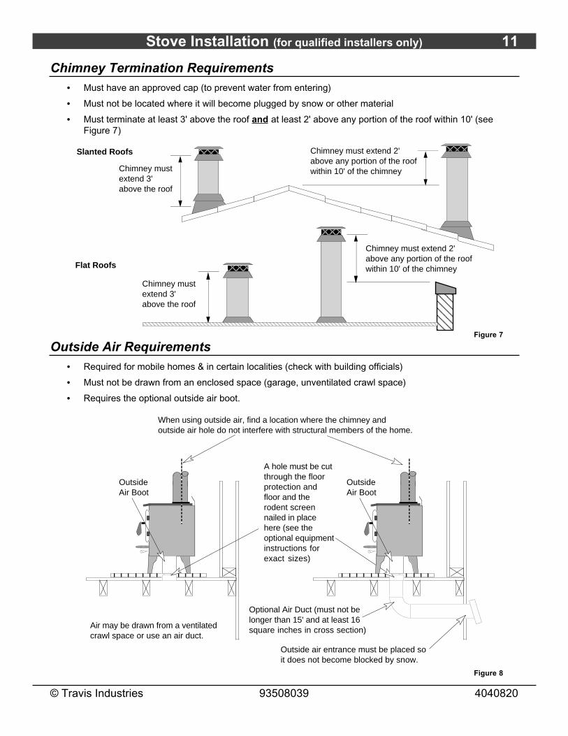
Chimney Termination Requirements• Must have an approved cap (to prevent water from entering)
• Must not be located where it will become plugged by snow or other material
• Must terminate at least 3' above the roof and at least 2' above any portion of the roof within 10' (seeFigure 7)
Slanted Roofs
Flat Roofs AA
AAAChimney must
extend 3' above the roof
AAAAAAAAAAAAAAA
Chimney must extend 2' above any portion of the roof within 10' of the chimney
AAAA
A AAAA
Chimney must extend 3' above the roof
Chimney must extend 2' above any portion of the roof within 10' of the chimney
Figure 7
Outside Air Requirements• Required for mobile homes & in certain localities (check with building officials)
• Must not be drawn from an enclosed space (garage, unventilated crawl space)
• Requires the optional outside air boot.
Optional Air Duct (must not be longer than 15' and at least 16 square inches in cross section)
A hole must be cut through the floor protection and floor and the rodent screen nailed in place here (see the optional equipment instructions for exact sizes)
Outside air entrance must be placed so it does not become blocked by snow.
When using outside air, find a location where the chimney and outside air hole do not interfere with structural members of the home.
Outside Air Boot
Air may be drawn from a ventilated crawl space or use an air duct.
Outside Air Boot
Figure 8
12 Stove Installation (for qualified installers only)
© Travis Industries 93508039 4040820
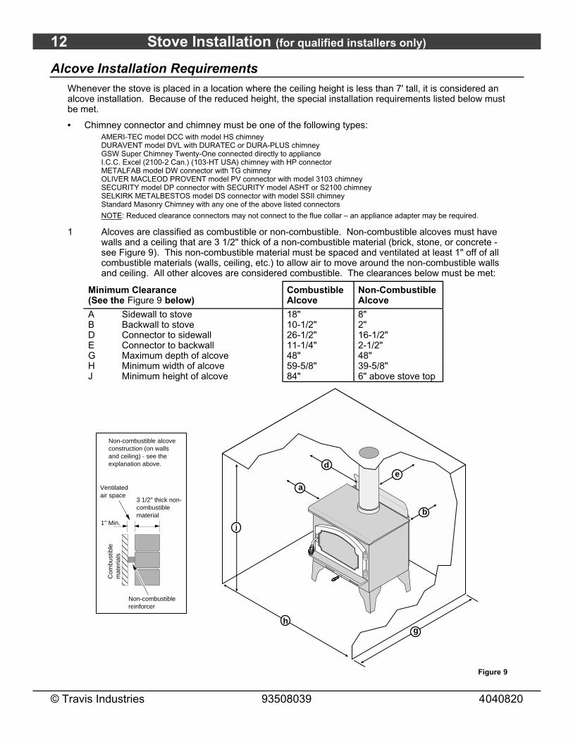
Alcove Installation RequirementsWhenever the stove is placed in a location where the ceiling height is less than 7' tall, it is considered analcove installation. Because of the reduced height, the special installation requirements listed below mustbe met.
• Chimney connector and chimney must be one of the following types:AMERI-TEC model DCC with model HS chimneyDURAVENT model DVL with DURATEC or DURA-PLUS chimneyGSW Super Chimney Twenty-One connected directly to applianceI.C.C. Excel (2100-2 Can.) (103-HT USA) chimney with HP connectorMETALFAB model DW connector with TG chimneyOLIVER MACLEOD PROVENT model PV connector with model 3103 chimneySECURITY model DP connector with SECURITY model ASHT or S2100 chimneySELKIRK METALBESTOS model DS connector with model SSII chimneyStandard Masonry Chimney with any one of the above listed connectors
NOTE: Reduced clearance connectors may not connect to the flue collar – an appliance adapter may be required.
1 Alcoves are classified as combustible or non-combustible. Non-combustible alcoves must havewalls and a ceiling that are 3 1/2" thick of a non-combustible material (brick, stone, or concrete -see Figure 9). This non-combustible material must be spaced and ventilated at least 1" off of allcombustible materials (walls, ceiling, etc.) to allow air to move around the non-combustible wallsand ceiling. All other alcoves are considered combustible. The clearances below must be met:
Minimum Clearance(See the Figure 9 below)
CombustibleAlcove
Non-CombustibleAlcove
A Sidewall to stove 18" 8"B Backwall to stove 10-1/2" 2"D Connector to sidewall 26-1/2" 16-1/2"E Connector to backwall 11-1/4" 2-1/2"G Maximum depth of alcove 48" 48"H Minimum width of alcove 59-5/8" 39-5/8"J Minimum height of alcove 84" 6" above stove top
Non-combustible alcove construction (on walls and ceiling) - see the explanation above.
AAAA
3 1/2" thick non-combustible material
Com
bust
ible
m
ater
ials
1" Min.
Ventilated air space
Non-combustible reinforcer
a
b
de
h
j
g
Figure 9
Stove Installation (for qualified installers only) 13
© Travis Industries 93508039 4040820
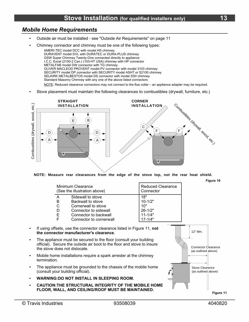
Mobile Home Requirements• Outside air must be installed - see "Outside Air Requirements" on page 11
• Chimney connector and chimney must be one of the following types:AMERI-TEC model DCC with model HS chimneyDURAVENT model DVL with DURATEC or DURA-PLUS chimneyGSW Super Chimney Twenty-One connected directly to applianceI.C.C. Excel (2100-2 Can.) (103-HT USA) chimney with HP connectorMETALFAB model DW connector with TG chimneyOLIVER MACLEOD PROVENT model PV connector with model 3103 chimneySECURITY model DP connector with SECURITY model ASHT or S2100 chimneySELKIRK METALBESTOS model DS connector with model SSII chimneyStandard Masonry Chimney with any one of the above listed connectors
NOTE: Reduced clearance connectors may not connect to the flue collar – an appliance adapter may be required.
• Stove placement must maintain the following clearances to combustibles (drywall, furniture, etc.)
STRAIGHT INSTALLATION
CORNER INSTALLATION
A
B
D
E
A
D FF
Com
bust
ible
s (d
ryw
all,
woo
d, e
tc.) Com
bustibles (drywall, wood, etc.)
NOTE: Measure rear clearances from the edge of the stove top, not the rear heat shield.
C
Figure 10
Minimum Clearance(See the illustration above)
Reduced ClearanceConnector
A Sidewall to stove 18"B Backwall to stove 10-1/2"C Cornerwall to stove 10"D Connector to sidewall 26-1/2"E Connector to backwall 11-1/4"F Connector to cornerwall 17-1/4"
• If using offsets, use the connector clearance listed in Figure 11, notthe connector manufacturer's clearance.
• The appliance must be secured to the floor (consult your buildingofficial). Secure the outside air boot to the floor and stove to insurethe stove does not dislocate.
• Mobile home installations require a spark arrester at the chimneytermination.
• The appliance must be grounded to the chassis of the mobile home(consult your building official).
• WARNING:DO NOT INSTALL IN SLEEPING ROOM.
• CAUTION:THE STRUCTURAL INTEGRITY OF THE MOBILE HOMEFLOOR, WALL, AND CEILING/ROOF MUST BE MAINTAINED.
12” Min.
Connector Clearance (as outlined above)
Stove Clearance (as outlined above)
AAAA
Figure 11
14 Stove Installation (for qualified installers only)
© Travis Industries 93508039 4040820
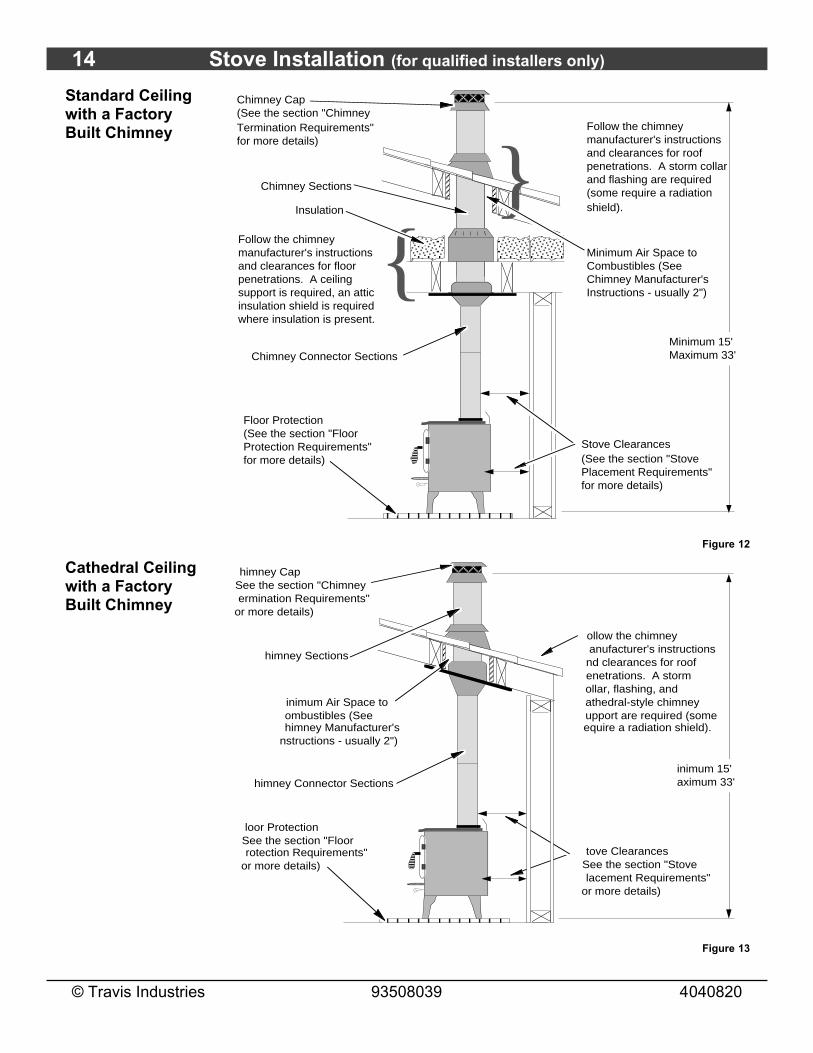
Standard Ceilingwith a FactoryBuilt Chimney
Chimney Cap(See the section "Chimney Termination Requirements" for more details)
Chimney Sections
Minimum Air Space to Combustibles (See Chimney Manufacturer's Instructions - usually 2")
Chimney Connector Sections
Follow the chimney manufacturer's instructions and clearances for roof penetrations. A storm collar and flashing are required (some require a radiation shield).}
}Minimum 15' Maximum 33'
Stove Clearances(See the section "Stove Placement Requirements" for more details)
Floor Protection(See the section "Floor Protection Requirements" for more details)
Follow the chimney manufacturer's instructions and clearances for floor penetrations. A ceiling support is required, an attic insulation shield is required where insulation is present.
Insulation
Figure 12
Cathedral Ceilingwith a FactoryBuilt Chimney
himney CapSee the section "Chimney ermination Requirements"
or more details)
himney Sections
inimum Air Space to ombustibles (See himney Manufacturer's
nstructions - usually 2")
himney Connector Sections
ollow the chimney anufacturer's instructions nd clearances for roof enetrations. A storm ollar, flashing, and athedral-style chimney upport are required (some equire a radiation shield).
inimum 15' aximum 33'
tove ClearancesSee the section "Stove lacement Requirements"
or more details)
loor ProtectionSee the section "Floor rotection Requirements"
or more details)
Figure 13

Stove Installation (for qualified installers only) 15
© Travis Industries 93508039 4040820
Exterior FactoryBuilt Chimney
NOTE:Exterior chimneys aresubject to greatermoisture and creosoteaccumulation due to thelower temperatures. Aninsulated chase willreduce theseaccumulations (theproper clearances to thechimney must bemaintained).
Chimney Cap(See the section "Chimney Termination Requirements" for more details)
Chimney Sections
Minimum Air Space to Combustibles (See Chimney Manufacturer's Instructions - usually 2")
Chimney Connector Sections
Floor Protection(See the section "Floor Protection Requirements" for more details)
Follow the chimney manufacturer's instructions and clearances for roof penetrations. A storm collar and flashing are required (some require a radiation shield).
}
tove ClearancesSee the section "Stove lacement Requirements"
or more details)
} ollow the chimney anufacturer's
nstructions and learances for wall enetrations. A wall adiation shield thimble) is required.
ptional nsulated hase
Wall Bands and Supports
Insulated Tee(with cleanout )
Minimum 15' Maximum 33'
Min. 18" clearance to ceiling
Figure 14
Hearth StovePositiveConnection
NOTE:
Most factory-builtchimney manufacturersmake stainless steelchimney liners, eitherflexible or rigid. Thisprovides a wide varietyof installation options.Make sure to follow themanufacturer'sinstructions forinstallation and support.
Remove damper or wire it open
Airtight Insulated Clean-Out
Min. 18"
Combustible Mantle
NOTE: This installation may be used with a masonry or zero clearance (metal) fireplace. The requirements in the section "Masonry Fireplace Requirements" or "Zero Clearance (metal) Fireplace Requirements" must be fulfilled prior to installation.
Flue Liner
Floor Protection(See the section "Floor Protection Requirements" for more details)
See the section "Stove Placement Requirements" for minimum clearances required.
The liner must be stainless steel connector or flexible vent. Follow the liner manufacturer's instructions for installation and support.
Cap (prevents water from entering)
Figure 15
16 Stove Installation (for qualified installers only)
© Travis Industries 93508039 4040820
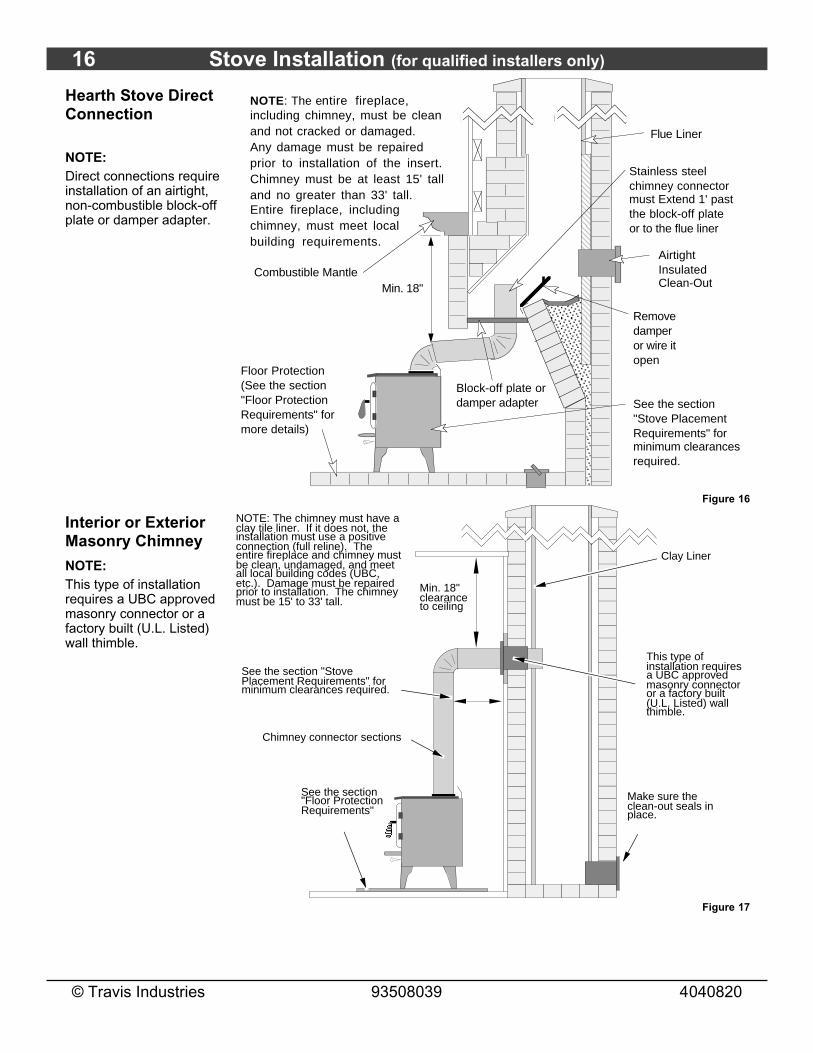
Hearth Stove DirectConnection
NOTE:Direct connections requireinstallation of an airtight,non-combustible block-offplate or damper adapter.
Block-off plate or damper adapter
Remove damper or wire it open
Airtight Insulated Clean-Out
Stainless steel chimney connector must Extend 1' past the block-off plate or to the flue liner
Min. 18" Combustible Mantle
Flue Liner
Floor Protection(See the section "Floor Protection Requirements" for more details)
See the section "Stove Placement Requirements" for minimum clearances required.
NOTE: The entire fireplace, including chimney, must be clean and not cracked or damaged. Any damage must be repaired prior to installation of the insert. Chimney must be at least 15' tall and no greater than 33' tall. Entire fireplace, including chimney, must meet local building requirements.
Figure 16
Interior or ExteriorMasonry Chimney
NOTE:This type of installationrequires a UBC approvedmasonry connector or afactory built (U.L. Listed)wall thimble.
Make sure the clean-out seals in place.
Clay Liner
See the section "Stove Placement Requirements" for minimum clearances required.
Min. 18" clearance to ceiling
This type of installation requires a UBC approved masonry connector or a factory built (U.L. Listed) wall thimble.
Chimney connector sections
NOTE: The chimney must have a clay tile liner. If it does not, the installation must use a positive connection (full reline). The entire fireplace and chimney must be clean, undamaged, and meet all local building codes (UBC, etc.). Damage must be repaired prior to installation. The chimney must be 15' to 33' tall.
See the section "Floor Protection Requirements"
AAAA
Figure 17

Operating Your Appliance 17
© Travis Industries 93508039 4040820
Safety NoticeIf this appliance is not properly installed, a house fire may result. For your safety, follow the installationdirections. Contact local building or fire officials about restrictions and installation inspectionrequirements in your area.
Read and follow all of the warnings on pages 4 and 5 of this manual.
Before Your First Fire
Verify the Installation
Before starting the stove, verify that the stove is properly installed and all of the requirements in thismanual have been followed.
Keep all flammable materials 36" away from the front of the stove (drapes, furniture, clothing, etc.).
Curing the Paint
This heater uses a heat-activated paint that will emit some fumes while startingthe first fire. Open doors and windows to the room to vent these fumes. Thistypically lasts two to four hours. You may also notice oil burning off of theinterior of the heater. This rust-stopping agent will soon dissipate.
Door Gasket - The door gasket might adhere to the paint on the front of theheater. Leave the door slightly ajar for the first fire and be careful when openingthe door after the first fire.
AAAAAAAAA
2 to 4 hours
Over-Firing the Stove
This stove was designed to operate at a high temperature. But due to differences in vent configuration,fuel, and draft, this appliance can be operated at an excessive temperature. If the stove top or other areastarts to glow red, you are over-firing the stove. Shut the air control down to low and allow the stove tocool before proceeding.
Over-firing may lead to damage of plated surfaces. If you are uncertain of over-firing conditions, wesuggest placing a stove thermometer (e.g. Rutland® Model 710) directly over the door on the stove top -temperatures exceeding 800° are generally considered over-firing and will void the warranty.
Opening the Door
Rotate
the door
handle.
Swing
the door
open.
The door becomes hot during use. Use a glove to open the door if the handle is hot.

18 Operating Your Appliance
© Travis Industries 93508039 4040820
Starting a FireSince the dawn of time man has debated the best way to start a fire. Some use the boy-scout "tee-pee",some prefer the "tic-tac-toe" stack. Either way, review the hints and warnings below to ensure proper firestarting.
• Make sure the air control is pushed in. If additional air is needed, open the doors 1/4" during the firstfive minutes of start-up.
Never use gasoline, gasoline-type lantern fuel, kerosene, charcoal lighter fluid, or similar liquids to startor "freshen up" a fire in this stove. Keep all such liquids well away from the stove while it is in use.
If using a firestarter, use only products specifically designed for stoves - follow the manufacturer'sinstructions carefully.
If the smoke does not pass up the chimney, ball up one sheet of newspaper, place it in the center of thefirebox and light it. This should start the chimney drafting (this eliminates "cold air blockage").
Use plenty of kindling to ensure the stove reaches a proper temperature. Once the kindling is burningrapidly, place a few larger pieces of wood onto the fire.

Operating Your Appliance 19
© Travis Industries 93508039 4040820
Adjusting the Burn RateUse the air control slider to control the burn rate of the stove. See the illustration below for details.
Low Burn(air control closed)
High Burn (air control open)
Use the air control to change the burn rate.
AAAAAAAA
Approximate Air Control SettingsOvernight Burn Fully out to 9/32" open
Medium Burn 9/32" to 5/16" open
Medium High Burn 5/16" to 7/16" open
High Burn 7/16" open top pushed fully in
The air control becomes hot during operation - use gloves or a tool to prevent burns.
The air control may take several minutes to influence the burn rate. When making adjustments, youmay wish to let the stove burn for 10 minutes to gauge performance.
Ash Removal
ASHES
Ashes should be placed in a metal container with a tight fitting lid. The closed container of ashesshould be placed on a noncombustible floor or on the ground, away from all combustiblematerials, pending final disposal. If the ashes are disposed of by burial in soil or otherwise locallydispersed, they should be retained in the closed container until all cinders have thoroughlycooled.
20 Operating Your Appliance
© Travis Industries 93508039 4040820
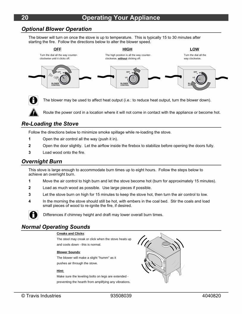
Optional Blower OperationThe blower will turn on once the stove is up to temperature. This is typically 15 to 30 minutes afterstarting the fire. Follow the directions below to alter the blower speed.
OFFTurn the dial all the way counter-clockwise until it clicks off.
BLOWER CONTROLAAAAAAAAAA
AAA
LO
OFF HI
HIGHThe high position is all the way counter-clockwise, without clicking off.
BLOWER CONTROLAAAAAAAAAA
AAA
LO
OFF HI
LOWTurn the dial all the way clockwise.
BLOWER CONTROLAAAAAAAAAA
AAA
LO
OFF HI
The blower may be used to affect heat output (i.e.: to reduce heat output, turn the blower down).
Route the power cord in a location where it will not come in contact with the appliance or become hot.
Re-Loading the StoveFollow the directions below to minimize smoke spillage while re-loading the stove.
1 Open the air control all the way (push it in).
2 Open the door slightly. Let the airflow inside the firebox to stabilize before opening the doors fully.
3 Load wood onto the fire.
Overnight BurnThis stove is large enough to accommodate burn times up to eight hours. Follow the steps below toachieve an overnight burn.
1 Move the air control to high burn and let the stove become hot (burn for approximately 15 minutes).
2 Load as much wood as possible. Use large pieces if possible.
3 Let the stove burn on high for 15 minutes to keep the stove hot, then turn the air control to low.
4 In the morning the stove should still be hot, with embers in the coal bed. Stir the coals and loadsmall pieces of wood to re-ignite the fire, if desired.
Differences if chimney height and draft may lower overall burn times.
Normal Operating SoundsCreaks and Clicks:
The steel may creak or click when the stove heats up
and cools down - this is normal.
Blower Sounds:
The blower will make a slight "humm" as it
pushes air through the stove.
Hint:
Make sure the leveling bolts on legs are extended -
preventing the hearth from amplifying any vibrations.
Operating Your Appliance 21
© Travis Industries 93508039 4040820
Hints for Burning• Get the appliance hot before adjusting to low burn
• Use smaller pieces of wood during start-up and high burns to increase temperature
• Use larger pieces of wood for overnight or sustained burns
• Stack the wood tightly together to establish a longer burn
• Leave a bed of ashes (1/2" deep) to allow for longer burns
• Be considerate of neighbors & the environment: burn dry wood only
• Burn small, intense fires instead of large, slow burning fires when possible
• Learn your appliance's operating characteristics to obtain optimum performance
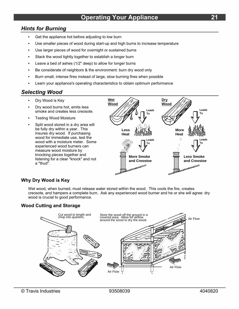
Selecting Wood• Dry Wood is Key
• Dry wood burns hot, emits lesssmoke and creates less creosote.
• Testing Wood Moisture
• Split wood stored in a dry area willbe fully dry within a year. Thisinsures dry wood. If purchasingwood for immediate use, test thewood with a moisture meter. Someexperienced wood burners canmeasure wood moisture byknocking pieces together andlistening for a clear "knock" and nota "thud".
Wet Wood
Leads To
Leads To
Dry Wood
Leads To
Leads To
Less Heat
More Heat
More Smoke and Creostoe
Less Smoke and Creostoe
Why Dry Wood is Key
Wet wood, when burned, must release water stored within the wood. This cools the fire, createscreosote, and hampers a complete burn. Ask any experienced wood burner and he or she will agree: drywood is crucial to good performance.
Wood Cutting and Storage
Cut wood to length and chop into quarters.
Store the wood off the ground in a covered area. Allow for airflow around the wood to dry the wood.
Air Flow
Air Flow
Air Flow
22 Operating Your Appliance
© Travis Industries 93508039 4040820
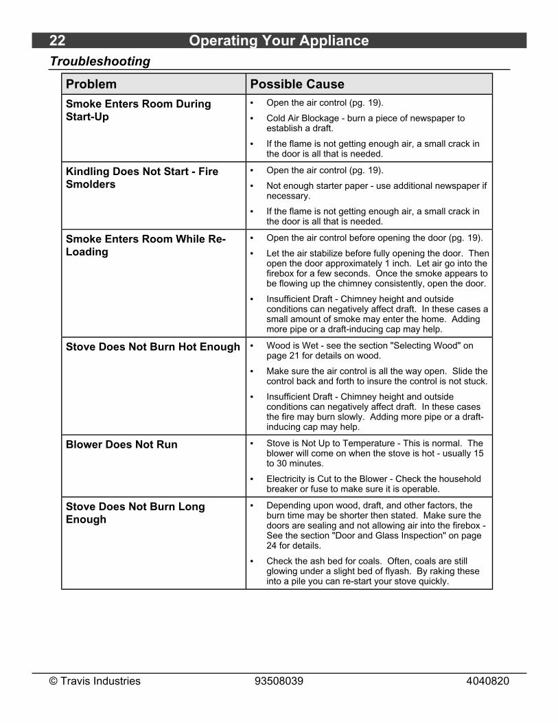
Troubleshooting
Problem Possible Cause
Smoke Enters Room DuringStart-Up
• Open the air control (pg. 19).
• Cold Air Blockage - burn a piece of newspaper toestablish a draft.
• If the flame is not getting enough air, a small crack inthe door is all that is needed.
Kindling Does Not Start - FireSmolders
• Open the air control (pg. 19).
• Not enough starter paper - use additional newspaper ifnecessary.
• If the flame is not getting enough air, a small crack inthe door is all that is needed.
Smoke Enters Room While Re-Loading
• Open the air control before opening the door (pg. 19).
• Let the air stabilize before fully opening the door. Thenopen the door approximately 1 inch. Let air go into thefirebox for a few seconds. Once the smoke appears tobe flowing up the chimney consistently, open the door.
• Insufficient Draft - Chimney height and outsideconditions can negatively affect draft. In these cases asmall amount of smoke may enter the home. Addingmore pipe or a draft-inducing cap may help.
Stove Does Not Burn Hot Enough • Wood is Wet - see the section "Selecting Wood" onpage 21 for details on wood.
• Make sure the air control is all the way open. Slide thecontrol back and forth to insure the control is not stuck.
• Insufficient Draft - Chimney height and outsideconditions can negatively affect draft. In these casesthe fire may burn slowly. Adding more pipe or a draft-inducing cap may help.
Blower Does Not Run • Stove is Not Up to Temperature - This is normal. Theblower will come on when the stove is hot - usually 15to 30 minutes.
• Electricity is Cut to the Blower - Check the householdbreaker or fuse to make sure it is operable.
Stove Does Not Burn LongEnough
• Depending upon wood, draft, and other factors, theburn time may be shorter then stated. Make sure thedoors are sealing and not allowing air into the firebox -See the section "Door and Glass Inspection" on page24 for details.
• Check the ash bed for coals. Often, coals are stillglowing under a slight bed of flyash. By raking theseinto a pile you can re-start your stove quickly.

Maintaining Your Appliance 23
© Travis Industries 93508039 4040820
Failure to properly maintain and inspect your appliance may reduce the performance and life of theappliance, void your warranty, and create a fire hazard.
Daily Maintenance (while stove is in use)
Remove Ash (if necessary)
• Ash removal is not required once it builds up. 1/2" to 1" of ash may be desirable because it slows theburn rate. Generally, remove ash once it has built up over 1". Follow the directions below to removeash.
1 Let the stove cool completely (at least two hours after the last coal has extinguished).
2 Place a cloth or cardboard protector over the hearth to catch ash and protect againstscratching.
3 Open the doors and scoop the ash into a metal container with a tight fitting lid. Theclosed container of ashes should be placed on a noncombustible floor or on theground, away from all combustible materials, pending final disposal.
ASHES
Improperly disposed ashes lead to fires. Hot ashes placed in cardboard boxes, dumped in back yards,or stored in garages, are recipes for disaster.
Wood-burning stoves are inherently dirty. During cleaning have a vacuum ready to catch spilled ash(make sure ash is entirely extinguished).
There are vacuum cleaners specifically made to remove ash (even if the ash is warm). Contact yourdealer for details.
Clean the Glass (if necessary)
This appliance has an airwash to keep the glass clean. However, burning un-seasoned wood or burningon lower burn rates leads to dirtier glass (especially on the sides). Clean the glass by following thedirections below.
For Stubborn Creosote:Dip newspaper or a paper towel in cool ashes and wipe it on the glass. The ash acts as a light abrasive.
Allow the stove to fully cool. Apply glass cleaner or soapy water to the inside of the glass. Wipe with newspaper or a paper towel.
AAAA
AAAA
The glass will develop a very slight haze over time. This is normal and will not affect viewing of the fire.
24 Maintaining Your Appliance
© Travis Industries 93508039 4040820
Monthly Maintenance (while appliance is in use)
Make sure the appliance has fully cooled prior to conducting service.
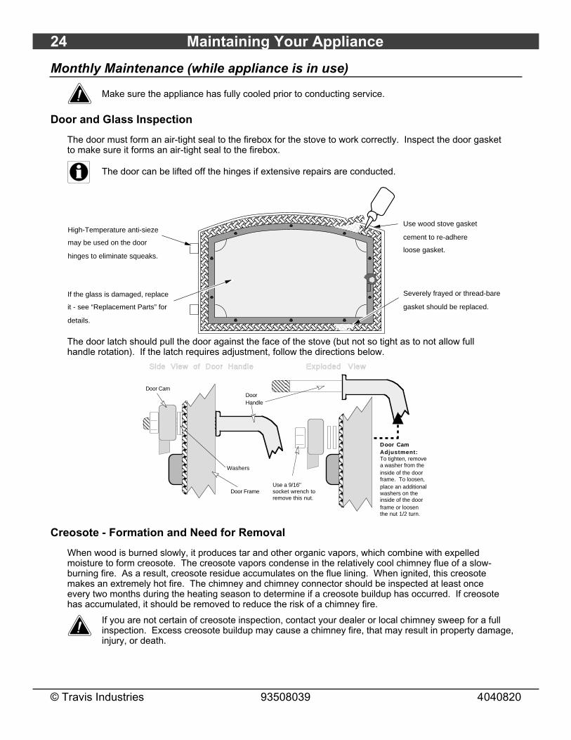
Door and Glass Inspection
The door must form an air-tight seal to the firebox for the stove to work correctly. Inspect the door gasketto make sure it forms an air-tight seal to the firebox.
The door can be lifted off the hinges if extensive repairs are conducted.
AAAAAAAAAAAAAAAAAAAAAAAAAAAAAAAAAAAAAAAAAAAAAAAAAAAAAAAAAAAAAAAAAAAAAA
AAAA
AA
Severely frayed or thread-bare
gasket should be replaced.
Use wood stove gasket
cement to re-adhere
loose gasket.
If the glass is damaged, replace
it - see “Replacement Parts” for
details.
High-Temperature anti-sieze
may be used on the door
hinges to eliminate squeaks.
AAAA
The door latch should pull the door against the face of the stove (but not so tight as to not allow fullhandle rotation). If the latch requires adjustment, follow the directions below.
Door CamDoor Handle
Washers
Door FrameUse a 9/16" socket wrench to remove this nut.
Side View of Door Handle
Door Cam Adjustment:To tighten, remove a washer from the inside of the door frame. To loosen, place an additional washers on the inside of the door frame or loosen the nut 1/2 turn.
Exploded View
Creosote - Formation and Need for Removal
When wood is burned slowly, it produces tar and other organic vapors, which combine with expelledmoisture to form creosote. The creosote vapors condense in the relatively cool chimney flue of a slow-burning fire. As a result, creosote residue accumulates on the flue lining. When ignited, this creosotemakes an extremely hot fire. The chimney and chimney connector should be inspected at least onceevery two months during the heating season to determine if a creosote buildup has occurred. If creosotehas accumulated, it should be removed to reduce the risk of a chimney fire.
If you are not certain of creosote inspection, contact your dealer or local chimney sweep for a fullinspection. Excess creosote buildup may cause a chimney fire, that may result in property damage,injury, or death.

Maintaining Your Appliance 25
© Travis Industries 93508039 4040820
Yearly MaintenanceMake sure the appliance has fully cooled prior to conducting service.
Touch Up Paint
Included with the owner's pack of this appliance is a can of Stove-Brite®paint. To touch up nicks or dulled paint, apply the paint while the appliance iscool. Sand rusted or damaged areas before preparation (use 120 gritsandpaper). Clean and dry the area to prepare the surface. Wait at least onehour before starting the appliance. The touched up area will appear darkerthan the surrounding paint until it cures from heat. Curing will give off somefumes while curing – open windows to ventilate.
Touch-Up
P a i n t
Cleaning the Air Duct and Blower (if applicable)
Use a vacuum to clean the air ducts (channels). This prevents dust from burning and creating odors.
The optional blower should be vacuumed every year to remove any buildup of dust, lint, etc.
Use a vacuum cleaner to remove any
buildup on the screens of the blower.
BOTTOM OF STOVE
Firebrick and Baffle Inspection
Use the illustration on page 27 as a reference for checking the following items. Make sure the applianceis cool before proceeding.
Baffle Firebricks - check the bricks along the ceiling of the firebox to make sure they are intact and haveno gaps between them. Slide the bricks to eliminate any gaps.
Baffle Supports - make sure the front and back baffle supports in are place and not degraded. Slightscaling or rusting of the metal is normal.
Secondary Air Tubes - Check the two air tubes and collars to make sure they are intact and not severelydeteriorated. Slight scaling or rusting of the metal is normal. Make sure the push pins hold the air tubesin place.
Floor and Wall Firebricks - replace any severely damaged firebrick along the side or floor of the firebox.

26 Maintaining Your Appliance
© Travis Industries 93508039 4040820
Door Parts
9/16" Wrench
5
10
8
912
7
6
3
4
AAAAAAAAAAAAAAAAAAAAAAAAAAAAAAAAAAAAAAAAAAAAAAAAA
1
2
11
NOTE: Place the glass gasket around the perimeter of the door retainer.
NOTE: Glue the door gasket to the door retainer.
# 20 Torx Driver
13
AAAAAAAAAAAAAAAAAAAAAAAAAAAAAA
14
1/8” Hex Wrench
ID # Description Qty Part # ID # Description Qty Part #1 Door Shell - Black
Door Shell - BrassDoor Shell - Pewter
1 230-00570230-00572230-00568
2 Glass (15-3/8" x 8-7/8") 1 173-01002
3 Glass Gasket 1 224-11086 4 Door Retainer (w gasket) 1 224-230205 Gasket Cement 1 99900409 6 Door Gasket 1 999004077 Door Handle Asbly - Black
Door Handle Asbly - BrassDoor Handle Asbly - Pewter
1 224-1404299900410224-14052
8 Spring - BlackSpring - BrassSpring - Pewter
1 100-1412299300100100-04103
9 Washers 2 100-03501 10 Cam 1 9990041711 Nut, Brass 1 101-00007 12 Glass Clips - Top
Glass Clip - Bottom21
224-230022224-230021
13 #8-32 3/8" Type F Screw 8 225-20039 14 Set Screw 2 225-20038
Replacing the Glass
The glass must not contact the door retainer or glass clips directly. The glass gasket and glass clipgaskets insulate the glass to prevent cracking. Do not over-tighten the glass clips.
See the illustration above for details on removing the door handle and shell. NOTE: The glass gasket isplaced in the grove along the inside perimeter of the door retainer. Make sure the glass clip screws areall fully tightened - they must be flush with the door retainer for the door shell to install.
Replacing the Door Gasket
The door gasket inserts into the outer groove of the door retainer. Stove gasket cement holds it in place.Before installing, remove any residual cement. Lay the gasket in place (start at the lower left corner) andcut off any excess gasket (do not stretch the gasket. The cement fully cures with heat from the stove.You may need to open and close the door repeatedly to get the gasket to seat fully.
Replacing the Door Handle
See the illustration above for a component list (see pg. 24 for details on adjusting the door).
Maintaining Your Appliance 27
© Travis Industries 93508039 4040820
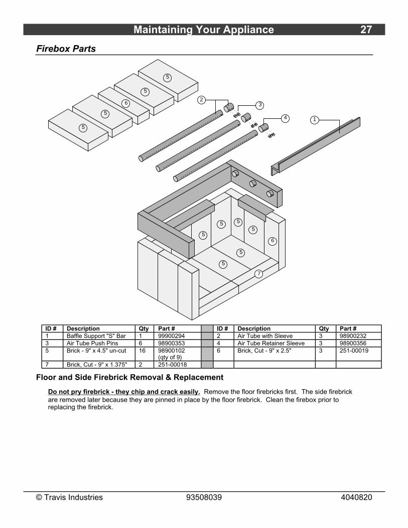
Firebox Parts
32
14
5
6
7
5
555
5
5
5
5
5
6
ID # Description Qty Part # ID # Description Qty Part #1 Baffle Support "S" Bar 1 99900294 2 Air Tube with Sleeve 3 989002323 Air Tube Push Pins 6 98900353 4 Air Tube Retainer Sleeve 3 989003565 Brick - 9" x 4.5" un-cut 16 98900102
(qty of 9)6 Brick, Cut - 9" x 2.5" 3 251-00019
7 Brick, Cut - 9" x 1.375" 2 251-00018
Floor and Side Firebrick Removal & Replacement
Do not pry firebrick - they chip and crack easily. Remove the floor firebricks first. The side firebrickare removed later because they are pinned in place by the floor firebrick. Clean the firebox prior toreplacing the firebrick.
28 Maintaining Your Appliance
© Travis Industries 93508039 4040820
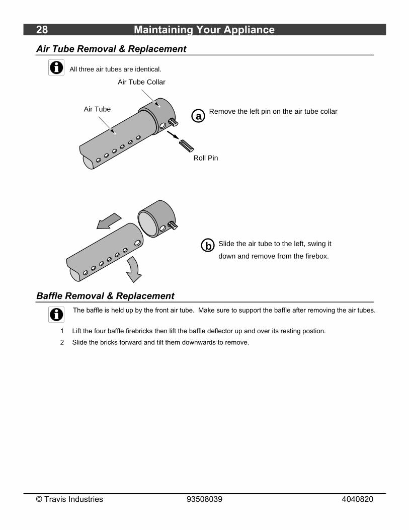
Air Tube Removal & Replacement
All three air tubes are identical.
a
b
Remove the left pin on the air tube collar
Air Tube Collar
Air Tube
Slide the air tube to the left, swing it
down and remove from the firebox.
Roll Pin
Baffle Removal & ReplacementThe baffle is held up by the front air tube. Make sure to support the baffle after removing the air tubes.
1 Lift the four baffle firebricks then lift the baffle deflector up and over its resting postion.
2 Slide the bricks forward and tilt them downwards to remove.

Limited 7 Year Warranty 29
© Travis Industries 93508039 4040820
To register your TRAVIS INDUSTRIES, INC. 7 Year Warranty, complete the enclosed warranty card and mail it within ten (10) days of the appliance purchasedate to: TRAVIS INDUSTRIES, INC., 4800 Harbour Pointe Blvd. SW, Mukilteo, WA 98275. TRAVIS INDUSTRIES, INC. warrants this gas appliance (appliance isdefined as the equipment manufactured by Travis Industries, Inc.) to be defect-free in material and workmanship to the original purchaser from the date ofpurchase as follows:
Check with your dealer in advance for any costs to you when arranging a warranty call.Mileage or service charges are not covered by this warranty. This charge can vary from store to store.
Years 1 & 2 - COVERAGE: PARTS & LABORFirebox Assembly:
Firebox, Baffle Supports, Air Tubes, Air Channels, Convection Chamber
Door Assembly:Solid Brass or Cast Door, Latch Assembly, Glass Retainers
Plated FinishPlated Door, Legs, etc… See "Conditions & Exclusions" # 9 below.
Air Control AssemblySlider Plate, Pressure Plate
Ceramic GlassGlass (breakage from thermal shock)
FirebrickBreakage from thermal shock
AccessoriesLegs, Pedestal, Panels, Blower
Re-Installation AllowanceIn cases where heater must be removed from homefor repairs, a partial cost of re-installation is covered(pre-authorization required)
One-Way Freight AllowanceOne-way freight allowance on pre-authorized repairdone at factory is covered.
Exclusions: Paint, Gasketing
Years 3 Through 5 - COVERAGE: PARTS & LABORFirebox Assembly:
Firebox, Baffle Supports, Air Tubes, Air Channels, Convection Chamber
Air Control AssemblySlider Plate, Pressure Plate
Door Assembly:Solid Brass or Cast Door, LatchAssembly, Glass Retainers
One-Way Freight AllowanceOne-way freight allowance on pre-authorizedrepair done at factory is covered.
Exclusions: Paint, Gasketing, Plated Finish, Accessories (Legs, Pedestal, Panels, Blower), Glass, Firebrick, Re-Installation Allowance
Years 6 & 7 - COVERAGE: PARTS ONLYFirebox Assembly:
Firebox, Baffle Supports, Air Tubes, Air Channels, Convection Chamber
Door Assembly:Solid Brass or Cast Door, Latch Assembly, Glass Retainers
Air Control AssemblySlider Plate, Pressure Plate
Exclusions: Paint, Gasketing, Plated Finish, Accessories (Legs, Pedestal, Panels, Blower), Glass, Firebrick, Re-Installation Allowance, One-Way Freight Allowance, Labor
CONDITIONS & EXCLUSIONS1. This new appliance must be installed by a qualified installer. It must be installed, operated, and maintained at all times in accordance with the instructions in the
Owner’s Manual. Any alteration, willful abuse, accident, neglect, or misuse of the product shall nullify this warranty.2. This warranty is nontransferable, and is made to the ORIGINAL purchaser, provided that the purchase was made through an authorized Travis dealer.3. Discoloration and some minor expansion, contraction, or movement of certain parts and resulting noise, is normal and not a defect and, therefore, not covered
under warranty. Over-firing (operation where the steel may glow red) of this appliance can cause serious damage and will nullify this warranty.4. The warranty, as outlined within this document, does not apply to the chimney components or other Non-Travis accessories used in conjunction with the
installation of this product. If in doubt as to the extent of this warranty, contact your authorized Travis retailer before installation.5. Travis Industries will not be responsible for inadequate performance caused by environmental conditions such as nearby trees, buildings, roof tops, wind, hills or
mountains or negative pressure or other influences from mechanical systems such as furnaces, fans, clothes dryers, etc.6. This Warranty is void if:
a. The unit has been operated in atmospheres contaminated by chlorine, fluorine or other damaging chemicals.b. The unit is subject to submersion in water or prolonged periods of dampness or condensation.c. Any damage to the unit, combustion chamber, heat exchanger or other components due to water, or weather damage which is the result of, but not
limited to, improper chimney/venting installation.7. Exclusions to this 7 Year Warranty include: injury, loss of use, damage, failure to function due to accident, negligence, misuse, improper installation, alteration or
adjustment of the manufacturer's settings of components, lack of proper and regular maintenance, damage incurred while the appliance is in transit, alteration, oract of God.
8. This 7 Year warranty excludes damage caused by normal wear and tear, such as paint discoloration or chipping, worn or torn gasketing, chipped or crackedfirebrick, etc. Also excluded is damage to the unit caused by abuse, improper installation, modification of the unit, or the use of fuel other than that for which theunit is configured (use cord wood only).
9. Damage to brass or plated surfaces caused by fingerprints, scratches, melted items, or other external sources left on the surfaces from the use of abrasivecleaners is not covered in this warranty. Damage to the surfaces from over-firing (operation where the steel may glow red) is not covered in this warranty.
10. TRAVIS INDUSTRIES, INC. is free of liability for any damages caused by the appliance, as well as inconvenience expenses and materials. Incidental orconsequential damages are not covered by this warranty. In some states, the exclusion of incidental or consequential damage may not apply.
11. This warranty does not cover any loss or damage incurred by the use or removal of any component or apparatus to or from the Travis appliance without theexpress written permission of TRAVIS INDUSTRIES, INC. and bearing a TRAVIS INDUSTRIES, INC. label of approval.
12. Any statement or representation of Travis products and their performance contained in Travis advertising, packaging literature, or printed material is not part ofthis 7 year warranty.
13. This warranty is automatically voided if the appliance’s serial number has been removed or altered in any way. If the appliance is used for commercial purposes,it is excluded from this warranty.
14. No dealer, distributor, or similar person has the authority to represent or warrant Travis products beyond the terms contained within this warranty. TRAVISINDUSTRIES, INC. assumes no liability for such warranties or representations.
15. Travis Industries will not cover the cost of the removal or re-installation of hearths, facing, mantels, venting or other components.16. If for any reason any section of this warranty is declared invalid, the balance of the warranty remains in effect and all other clauses shall remain in effect.17. This 7 year warranty is the only warranty supplied by Travis Industries, Inc., the manufacturer of the appliance. All other warranties, whether express or implied,
are hereby expressly disclaimed and purchaser’s recourse is expressly limited to the warranties set forth herein.
IF WARRANTY SERVICE IS NEEDED:1. If you discover a problem that you believe is covered by this warranty, you MUST REPORT it to your Travis dealer WITHIN 30 DAYS, giving them proof of
purchase, the purchase date, and the model name and serial number.2. Travis Industries has the option of either repairing or replacing the defective component.3. If your dealer is unable to repair your appliance’s defect, he may process a warranty claim through TRAVIS INDUSTRIES, INC., including the name of
the dealership where you purchased the appliance, a copy of your receipt showing the date of the appliance’s purchase, and the serial number on yourappliance. At that time, you may be asked to ship your appliance, freight charges prepaid, to TRAVIS INDUSTRIES, INC. TRAVIS INDUSTRIES, INC.,at its option, will repair or replace, free of charge, your appliance if it is found to be defective in material or workmanship within the time frame statedwithin this 7 year warranty. TRAVIS INDUSTRIES, INC. will return your appliance, freight charges (years 1 to 5) prepaid by TRAVIS INDUSTRIES,INC., to your regional distributor, or dealership.
4. Check with your dealer in advance for any costs to you when arranging a warranty call. Mileage or service charges are not covered by this warranty. This chargecan vary from store to store.
30 Listing Label
© Travis Industries 93508039 4040820
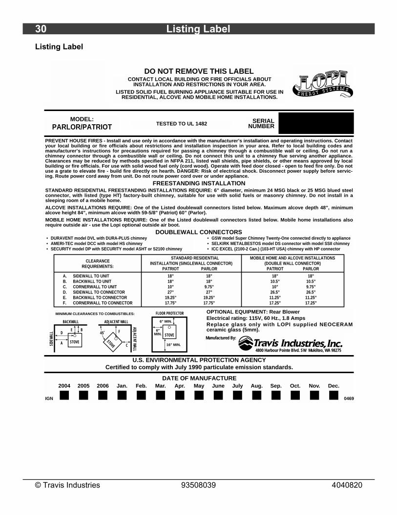
Listing Label
CONTACT LOCAL BUILDING OR FIRE OFFICIALS ABOUT INSTALLATION AND RESTRICTIONS IN YOUR AREA.
LISTED SOLID FUEL BURNING APPLIANCE SUITABLE FOR USE IN RESIDENTIAL, ALCOVE AND MOBILE HOME INSTALLATIONS.
PREVENT HOUSE FIRES - Install and use only in accordance with the manufacturer’s installation and operating instructions. Contactyour local building or fire officials about restrictions and installation inspection in your area. Refer to local building codes andmanufacturer’s instructions for precautions required for passing a chimney through a combustible wall or ceiling. Do not run achimney connector through a combustible wall or ceiling. Do not connect this unit to a chimney flue serving another appliance.Clearances may be reduced by methods specified in NFPA 211, listed wall shields, pipe shields, or other means approved by localbuilding or fire officials. For use with solid wood fuel only (cord wood). Operate with feed door closed - open to feed fire only. Do notuse a grate to elevate fire - build fire directly on hearth. DANGER: Risk of electrical shock. Disconnect power supply before servic-ing. Route power cord away from unit. Do not route power cord over or under appliance.
DO NOT REMOVE THIS LABEL
• DURAVENT model DVL with DURA-PLUS chimney• AMERI-TEC model DCC with model HS chimney• SECURITY model DP with SECURITY model ASHT or S2100 chimney
• GSW model Super Chimney Twenty-One connected directly to appliance• SELKIRK METALBESTOS model DS connector with model SSII chimney• ICC EXCEL (2100-2 Can.) (103-HT USA) chimney with HP connector
MODEL:PARLOR/PATRIOT TESTED TO UL 1482 SERIAL
NUMBER
FREESTANDING INSTALLATION
CLEARANCEREQUIREMENTS:
A. SIDEWALL TO UNITB. BACKWALL TO UNITC. CORNERWALL TO UNITD. SIDEWALL TO CONNECTORE. BACKWALL TO CONNECTORF. CORNERWALL TO CONNECTOR
STANDARD RESIDENTIALINSTALLATION (SINGLEWALL CONNECTOR)
PATRIOT PARLOR
18” 18”18” 18”10” 9.75”27” 27”
19.25” 19.25”17.75” 17.75”
MOBILE HOME AND ALCOVE INSTALLATIONS(DOUBLE WALL CONNECTOR)
PATRIOT PARLOR
18” 18”10.5” 10.5”10” 9.75”
26.5” 26.5”11.25” 11.25”17.25” 17.25”
STOVE
FLOOR PROTECTOR
6"MIN.
6" MIN.
16" MIN.
45˚
STOVE
ADJACENT WALL
ADJACENT WALL
F
CSTOVE
BACKWALL
SIDE
WALL
ED
B
A
MINIMUM CLEARANCES TO COMBUSTIBLES:
4800 Harbour Pointe Blvd. SW Mukilteo, WA 98275
Manufactured By:
STANDARD RESIDENTIAL FREESTANDING INSTALLATIONS REQUIRE: 6” diameter, minimum 24 MSG black or 25 MSG blued steelconnector, with listed (type HT) factory-built chimney, suitable for use with solid fuels or masonry chimney. Do not install in asleeping room of a mobile home.ALCOVE INSTALLATIONS REQUIRE: One of the Listed doublewall connectors listed below. Maximum alcove depth 48”, minimumalcove height 84”, minimum alcove width 59-5/8" (Patriot) 60” (Parlor).MOBILE HOME INSTALLATIONS REQUIRE: One of the Listed doublewall connectors listed below. Mobile home installations alsorequire outside air - use the Lopi optional outside air boot.
OPTIONAL EQUIPMENT: Rear Blower Electrical rating: 115V, 60 Hz., 1.8 AmpsReplace glass only with LOPI supplied NEOCERAMceramic glass (5mm).
U.S. ENVIRONMENTAL PROTECTION AGENCYCertified to comply with July 1990 particulate emission standards.
DOUBLEWALL CONNECTORS
2004 2005 2006 Jan. Feb. Mar. Apr. May June July Aug. Sep. Oct. Nov. Dec.DATE OF MANUFACTURE
0469IGN
Optional Equipment 31
© Travis Industries 93508039 4040820
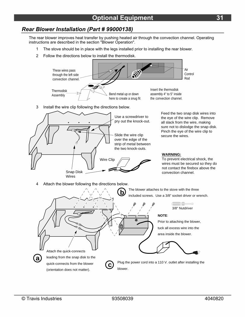
Rear Blower Installation (Part # 99000138)The rear blower improves heat transfer by pushing heated air through the convection channel. Operatinginstructions are described in the section "Blower Operation".
1 The stove should be in place with the legs installed prior to installing the rear blower.
2 Follow the directions below to install the thermodisk.
Air Control Rod
These wires pass through the left side convection channel.
Bend metal up or down here to create a snug fit
Thermodisk Assembly
Insert the thermodisk assembly 4" to 5" inside the convection channel.
3 Install the wire clip following the directions below.
Slide the wire clip over the edge of the strip of metal between the two knock-outs.
Feed the two snap disk wires into the eye of the wire clip. Remove all slack from the wire, making sure not to dislodge the snap disk. Pinch the eye of the wire clip to secure the wires.
Wire Clip
Snap Disk Wires
WARNING:To prevent electrical shock, the wires must be secured so they do not contact the firebox above the convection channel.
Use a screwdriver to pry out the knock-out.
4 Attach the blower following the directions below.
NOTE:
Prior to attaching the blower,
tuck all excess wire into the
area inside the blower.
The blower attaches to the stove with the three
included screws. Use a 3/8” socket driver or wrench.
Plug the power cord into a 110 V. outlet after installing the
blower.
Attach the quick-connects
leading from the snap disk to the
quick-connects from the blower
(orientation does not matter).
3/8" Nutdriver
a
b
c
AAAA

32 Optional Equipment
© Travis Industries 93508039 4040820
Outside Air Boot Installation (Part number 99200134)
The outside air boot routes outside air to the stove for combustion. Refer to the section "Outside AirRequirements" for installation concerns. The directions below detail installation.
1 Refer to the illustration below to determine the location and size of the hole penetrating the floorand hearth. The knock-out (which is pre-removed) is 5-13/16" behind the face of the stove. Markthe hole location after temporarily placing the stove, making sure all clearances and otherrequirements are met.
2 Attach gasket to the bottom edge of the lower air boot section (near the screen). Attach gasketon top of the flanges on the upper air boot section. Slide the two sections together with bothseams facing the rear (do not attach the two sections at this time).
3 Follow the directions below for attaching the upper section of the air boot (with gasket) to thestove.
4 Slide the lower section down until it contacts the hearth. Attach the two sections togetherfollowing the directions below
AAAA
AAAA
Bottom of Stove
8-7/8”
5-1/8”
Attach the air boot with
the two screws included
with the kit.
1/4" Nutdriver
Attach gasket to the bottom
edge of the air boot.
AAAAA
Attach the included
gasket to all four top
edges of the air boot.
Use the included screws to attach
the two telescoping portions of air
boot together. The included drill bit
should be used to drill the hole.
Make sure the air boot is expanded
to the correct size before drilling.
5/16" Nutdriver9/64” Drill Bit
AAAAAAAAAAAAAAAAAAAAAAAAAAAAAAAAAAAAAAAAAAAAAAAAAAAAAAA
AAAAAAAAAA
Floor (and hearth)
The hole in the floor (and hearth)
must be a minimum 16 square
inches. It should be 1/2” smaller
than the footprint of the air boot in
each dimension to allow for the
gasket to seal.
Use a
screwdriver to
pry out the
knock-out (if
applicable).

Optional Equipment 33
© Travis Industries 93508039 4040820

34 Index
© Travis Industries 93508039 4040820
Air Control ...................................................19Air Tube Part Number ....................................27Air Tube Removal & Replacement ....................28Alcove.........................................................12Ash Disposal ................................................23Baffle Parts ..................................................27Baffle Removal and Replacement .....................28Blower Cleaning............................................25Blower Does Not Run (Troubleshooting) ............22Blower Installation (rear) .................................31Blower Operation (optional) .............................20Burn Rate ....................................................19Cathedral Ceiling...........................................14Ceiling Penetration ........................................10Chimney Cleaning .........................................24Chimney Inspection (Creosote) ........................24Chimney Requirements ..................................10Chimney Termination Requirements..................11Cleaning the Ash...........................................23Cleaning the Glass ........................................23Clearances (stove) ........................................8Close Clearance Connectors ...........................8Connector Requirements ................................10Creosote Check ............................................24Daily Maintenance .........................................23Dimensions ..................................................6Door and Glass Inspection ..............................24Door Assembly .............................................26Door Gasket Replacement ..............................26Door Handle Replacement ..............................26Door Opening ...............................................17Door Parts ...................................................26Draft Performance .........................................10Elbows (Chimney) .........................................10Emissions ....................................................6EPA Approval ...............................................6Exterior Chimney...........................................11Features......................................................6Fire Starting .................................................18Firebox Assembly..........................................27Firebox Parts................................................27Firebrick and Baffle Inspection .........................25Firebrick Removal & Replacement ....................27Floor Protection Requirements (stove) ...............8Glass Cleaning .............................................23Glass Replacement .......................................26Hearth (Floor Protection - Stove) ......................8Hearth Stove ................................................16Heating Specifications ....................................6Hints for Burns..............................................21Installation Options ........................................6Installation (stove) .........................................7Leg Installation .............................................7Listing Label.................................................30Maintenance ................................................23Mobile Home Requirements ............................13
Monthly Maintenance .....................................24Noise (Normal Operating Sounds) ....................20Non-Combustible Alcove.................................12Opening the Door ..........................................17Operation ....................................................17Outside Air Boot Installation.............................32Outside Air...................................................11Over-Firing the Stove .....................................17Overnight Burn .............................................20Paint (Touch-Up Paint) ...................................25Paint Curing .................................................17Rear Blower Installation ..................................31Re-Loading the Stove.....................................20Safety Label .................................................30Safety Precautions ........................................4Smell (from paint curing) .................................17Smoke Enters Room (Troubleshooting)..............22Sounds (Normal Operating Sounds) ..................20Starting a Fire...............................................18Stove Does Not Burn Long Enough...................22Stove is Not Hot Enough (Troubleshooting) ........22Table of Contents ..........................................3Touch-Up Paint.............................................25Troubleshooting (Operation) ............................22Warranty Card ..............................................2Warranty .....................................................29Wood..........................................................21Yearly Maintenance .......................................25