Ozzi Kleen Owners Manual 16.10.09 · CONGRATULATIONS We would like to thank you for investing in an...
24
RP10 RP10A R
Transcript of Ozzi Kleen Owners Manual 16.10.09 · CONGRATULATIONS We would like to thank you for investing in an...

RP10RP10A
R

CONGRATULATIONS
We would like to thank you for investing in an Ozzi Kleen package sewage treatment plant.
An Ozzi Kleen treatment plant consists of a single tank using a cyclic aerobic biological treatment process, designed to take all of your household wastewater; i.e. toilets, bathrooms, kitchen and laundry. The effluent is then disinfected and may be reused on your garden.
Consider your Ozzi Kleen treatment plant as a small farm of micro-organisms consuming the waste that is discharged into it. Normal household wastewater will be biologically treated to produce high quality treated water which may be reused.
Suncoast Waste Water Management specialise in domestic and commercial waste water solutions.
Page 1
Document No: P002Revision: LRevision Date: 08/08/2008

TABLE OF CONTENTS Interpretation......................................................................................................... 3 Statement .............................................................................................................. 3 Models Available................................................................................................... 3 Manufacturer’s Warranty..................................................................................... 4 Installation Instructions....................................................................................... 5 Plumber’s Installation Certificate........................................................................ 7 Electrical Requirements....................................................................................... 8 How the Ozzi Kleen Treatment Plant Works....................................................... 10 Operating Instructions....................................................................................... 12 Vacation of Premises ......................................................................................... 14 Treatment Plant Servicing ................................................................................. 14 Troubleshooting Guide...................................................................................... 15 Specifications ..................................................................................................... 17 System Drawing.................................................................................................. 18 Safety Information.............................................................................................. 19
Page 2
Optional Rapid Sand Filtration System Operating Instructions................... 19
Document No: P002Revision: LRevision Date: 08/08/2008

INTERPRETATION
(i) 'Manufacturer' includes Neatport Pty. Ltd. A.C.N. 063 770 534 trading as Suncoast Waste Water Management.
(ii) 'Purchaser/Owner' shall mean the registered proprietor of the property where the Ozzi Kleen Sewage treatment plant has been installed.
STATEMENT
We, the manufacturer of the OZZI KLEEN sewage treatment systems, confirm that our treatment plants meet the requirements of the State Regulatory Authorities.
This equipment is covered under a manufacturer's warranty as per the warranty conditions on page 4 of the Owner's Manual.
This system has been designed to treat normal household sewage to the required standards as set by the State Regulatory Authorities. This also precludes any use of garbage grinders connected to the system.
The wastewater discharged to the system should not contain foreign matter such as: disposable nappies, tampons, sanitary napkins, condoms, plastics, paint, thinners, contents of a portable chemical toilet, or waste from garbage grinders, etc. The wastewater should not contain excessive amounts of harsh cleaners, disinfectants, fats, oils or grease.
This manual is for owners of the OZZI KLEEN system, which describes the proper function of the treatment plant, operating and maintenance responsibilities of the Owner and authorised personnel, and any service-related obligations of the Manufacturer.
MODELS AVAILABLE
RP10 (Standard)RP10A (Advanced - Nutrient Removal)
OptionalSand Filtration (Effluent Polishing)U.V. Disinfection
Page 3
Document No: P002Revision: LRevision Date: 08/08/2008

OZZI KLEEN MANUFACTURER'S WARRANTY
Warranty is subject to the return of a signed PLUMBER'S INSTALLATION CERTIFICATE.This Certificate is to be filled out and returned to the manufacturer as part of the Owner's Warranty Registration.
1. Suncoast Waste Water Management warrants to the original purchaser that all equipment manufactured by Suncoast Waste Water Management is free from defect in material and construction at the time of despatch from the premises of Suncoast Waste Water Management.
2. This warranty is a return to base warranty which means the item must be returned to the manufacturer for repair. An exchange unit may be provided in this case. If replacement or service under this warranty policy is required and distance prevents you calling personally, forward your product freight prepaid to your nearest Service Provider.
3. This warranty does not extend to any claim made after a fixed period from the date of purchase for the following equipment:� Air Blower 24 months� Effluent Pump 24 months� Electrical components 12 months� Electronic Control Box 12 months� Main Tank 15 years
4. All claims for warranty must be done through the retailer or supplier from whom the product was purchased. Proof of purchase must be supplied.
5. Any claim made in relation to this warranty is limited to the cost of replacement or repair of the equipment or such parts thereof claim defective.
.6. In the case of ancillary parts not manufactured by Suncoast Waste Water Management such as pumps, motors, starters, switches etc.,
the guarantee or warranty extended to the purchaser will be limited to the guarantee or warranty available from the manufacturer of that part.
7. This warranty is valid only when the equipment has been used in a normal manner and in accordance with the Owner's Manual and serviced by a duly authorised Ozzi Kleen Service Provider every 3 months.
8. This warranty does not cover any equipment that has been improperly installed, misused, neglected, damaged in transport, repaired without the authorisation of Suncoast Waste Water Management or altered in any way from its original condition at the date of purchase.
9. Adverse operating conditions beyond the control of Suncoast Waste Water Management such as improper voltage, water pressure, excessive ambient temperature, water damage, flooding, or any condition that adversely affects the performance or life of the equipment will render this warranty null and void.
10. Any costs incurred to repair a unit that is not covered by warranty will be passed on to the consumer including costs incurred to remove the faulty unit and replace with an exchange unit. Suncoast Waste Water Management is not responsible for any costs for goods not covered by this warranty.
11. Warranty work will not be performed until the customer has accepted the price quoted for the service call. Suncoast Waste Water Management will designate a minimum charge.
Warranty does not cover:
� Cleaning sprinklers of any blockages or damage to equipment caused by not clearing blockages.� Any operational problems due to extraneous matter, fats or chemical spills in the sewage.� Any parts broken or stolen from within the system due to transport or installation or misuse by any unauthorised persons.� Any changes that are made to the treatment plant system from the original manufacture that is not
approved by the manufacturer including components that maybe modified removed or replaced that alters the treatment processes.
� Service Provider's time for replacement of any faulty parts or cleaning out of treatment system.� Service Provider's travel expenses (vehicle and travel time).� Service callout costs.� No warranty if the system has been used as an external power supply for other electrical appliances.� No warranty if the seal on the control box has been broken.
Page 4
Document No: P002Revision: LRevision Date: 08/08/2008

INSTALLATION INSTRUCTIONS
* Extract from Installation Manual - supplied with system, found in motor box.
PLUMBER'S INSTALLATION INSTRUCTIONS
� A hole for installation will have to be excavated approximately 2.5 m across and 2.4 m deep with a sound base.
� A layer of bedding sand is required (refer to drawing).� If the hole is over excavated, extra bedding sand will be required.� A normal installation of the treatment plant will locate the level of the sewer invert at 700 mm
below natural ground level and 1600 mm above the sand base.
1. Install the treatment plant so that the tank is located central in the excavated hole with no less than 250 mm to the nearest side. Ensure that the backfill is placed evenly around the tank (see drawing).
If the system is placed unevenly in the hole so that the tank is near to touching a side of the hole this will not allow for even backfill and cause tank instability and will have to be rectified by the installer.
2. Install the treatment plant so that the base of the green motor box is no less than 50 mm above the natural ground level to avoid surface water entry.
If the system is installed too low it will have to be rectified by the installer.
3. The Ozzi Kleen treatment plant is to be completely filled with water (approximately 4,500 litres) or up to the sewer inlet before any backfill is placed around the tank. All compartments including sludge waste and effluent compartments must be filled.
Failure to do so will cause tank instability and any deflection to the tank will have to be rectified by the installer.
4. The system is to be installed in a position where local storm water flooding and ponding around the tank will not occur.
If the system is installed in a watercourse or a flood prone area the system will have to be relocated by the installer.
5. Landscaping or the importation of topsoil that is placed around the system after it is installed, which would cause the tank to be too low in the ground is to be avoided. No rocks are to be placed on top of the system or within 1 m of the system.
Imported topsoil that may be placed on the system after the installation will be the responsibility of the installer or owner.
6. When installing the system underneath a building ensures that there is sufficient head room for servicing.
A minimum of 1200 mm head room is needed for the service removal of some parts and retrieving of water samples at time of service.
Page 5
Document No: P002Revision: LRevision Date: 08/08/2008

IMPORTANT: TANK IS TO BE CENTRALLY LOCATED IN THE EXCAVATED HOLE WITH NO LESS THAN 250 mm CLEARANCE AT THE NEAREST POINT.
GROUND LEVELDO NOT BURY TANK BELOW THIS LEVEL
EFFLUENTDISCHARGE
MINIMUMWATER LEVEL SEWER INLET
100 mm BEDDING SAND
16
00
mm
70
0 m
m
POWER CONNECTION
SEWER INLET
EFFLUENTDISCHARGE
250 mm
250 mmMINIMUM
CLEARANCE
EDGE OF HOLE
HOLE EXCAVATION NO LESS THAN 2.5 m APPROX
TANK 1
TANK 2
MAIN TANK
TANK 1TANK 2MAIN TANK
24
00
mm
HOLE EXCAVATION NO LESS THAN 2.5 m APPROX
Top View
Side View
IMPORTANT: FILL TANKS 1 & 2 FOLLOWED BY MAIN TANK WITH WATER, (APPROXIMATELY 4,500 LITRES) PRIOR TO BACKFILLING.
INSTALLATION INSTRUCTIONS (continued)
Page 6
Document No: P002Revision: LRevision Date: 08/08/2008

PLUMBER'S INSTALLATION CERTIFICATE
The Ozzi Kleen System must be installed as per the following instructions. This form is to be filled out and returned to the manufacturer or their agent as part of the Owner's warranty registration.
PLEASE TICK ALL THE BOXES DURING THE INSTALLATION
1. Excavate hole - 2.5 m diameter and approximately 2.4 m deep
2. Place a layer of bedding sand in the hole
3. Check depth from sand bed to natural ground level no greater than 2300 mm
4. Check depth from sewer invert to bedding sand no greater than 1600 mm
5. Check depth of sewer invert to natural ground level no greater than 700 mm
6. Check that motor box hinges are at least 50 mm above the natural ground level
7. Fill tanks 1 & 2 followed by main tank to sewer inlet with water (approximately 4,500 litres)
8. Connect sewer piping to the sewer inlet
9. Backfill around tank with clean earth only, (free from large lumps of clay, stones, bricks, foreign objects, or dumped rubbish from other trades persons)
10. The irrigation system could be of several different formats, check for Council requirements
INSTALLATION CERTIFICATION
The Ozzi Kleen system has been installed according to the above procedures by an approved installer.
OZZI KLEEN SERIAL No:
NAME OF INSTALLER:
INSTALLER'S LICENCE No:
INSTALLER'S SIGNATURE:
DATE OF INSTALLATION:
LOCATION OF INSTALLATION:
Page 7
Document No: P002Revision: LRevision Date: 08/08/2008
Page 8
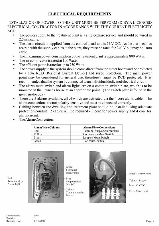
ELECTRICAL REQUIREMENTS
INSTALLATION OF POWER TO THIS UNIT MUST BE PERFORMED BY A LICENCED ELECTRICAL CONTRACTOR IN ACCORDANCE WITH THE CURRENT ELECTRICITY ACT.� The power supply to the treatment plant is a single-phase service and should be wired in
2.5mm cable.� The alarm circuit is supplied from the control board and is 24 V DC. As the alarm cables
are run with the supply cables to the plant, they must be rated for 240 V but may be 1mm cable.
� The maximum power consumption of the treatment plant is approximately 800 Watts.� The air compressor is rated at 100 Watts.� The effluent pump is rated at up to 750 Watts.� The power supply to the system should come direct from the meter board and be protected
by a 10A RCD (Residual Current Device) and surge protection. The main power point may be considered for general use, therefore it must be RCD protected. It is recommended that the system be connected to an individual dedicated electrical circuit.
� The alarm mute switch and alarm lights are on a common switch plate, which is to be mounted in the Owner's house at an appropriate point. (The switch plate is found in the green motor box).
� There are 3 alarms available, all of which are activated via the 4 core alarm cable. The alarm connections are not polarity sensitive and must be connected correctly.
� Cabling between the dwelling and treatment plant should be installed using adequate protection/conduit. 2 cables will be required - 3 core for power supply and 4 core for alarm circuit.
� The Alarm Connections
Alarm Wire Colours Alarm Plate ConnectionsRed Terminal Strip on Alarm PanelYellow Common on Mute SwitchBlue Loop on Mute SwitchGreen 1 on Mute Switch
Document No: P002Revision: LRevision Date: 08/08/2008
RedTerminal stripAlarm light
Green1 terminalBuzzer mute
Blue Loop terminalO V DC
Yellow Common terminalBuzzer
Green - Buzzer mute
Yellow - Buzzer
Blue - O V DC
Red - Alarm light

ELECTRICAL REQUIREMENTS (cont)
The power supply cable is brought into the treatment plant through the side of the square tank turret at the top of the tank, referred to as the access manhole, and up through the floor of the motor box housed in the flexible conduit provided. The 240 V supply is to be connected to the main power outlet inside the motor box. The low voltage alarm wires are to be connected to the terminals inside the small round junction box below the main power outlet. The external electrical conduit to the system is to be 25mm.
Note: The motor compartment on the top of the treatment plant is on a hinged lid and the wiring to this compartment passes through a flexible conduit provided. No external conduit or rigid conduit is to be fastened to the outside of the motor box. If extra flexible conduit is used for wire connection to the system, ensure that there is sufficient length to allow for the tilting of the motor box when it is opened.
The power supply cable is to be connected to the weatherproof outlet provided and alarm cable to be connected to the terminal strip inside the PVC junction box provided. No other connections are required. High voltage and low voltage wires can share a common conduit providing the insulation on the low voltage wires are equal to the high voltage wires.
Page 9
Document No: P002Revision: LRevision Date: 08/08/2008

HOW THE OZZI KLEEN TREATMENT PLANT WORKS
OZZI KLEEN works with a cycled aeration process which consists of a single tank designed to accept and treat all the household sewage; i.e. sewage from toilets, bathrooms, kitchen and laundry. The process is similar to the tried and tested method used in municipal treatment plants. The waste products in the sewage are completely consumed by naturally occurring bacteria in the oxygen-rich environment in the aeration tank. The system treats the organic waste to produce treated water of a high standard.
The cycled aeration system process consists of three main cycles, i.e:
Aeration CycleThe incoming sewage is aerated and oxygenated with air supplied by the air blower. As aeration takes place, an aerobic environment is provided for micro-organisms. These organisms grow and establish an “activated sludge”. The activated sludge will oxidise the organic waste as long as a balance between the air feed and the organic/hydraulic load is maintained.
Settling CycleAfter the aeration cycle, aeration ceases for approximately 30 minutes, allowing the activated sludge to settle to the bottom of the aeration tank. A layer of clear water is then formed at the top of the aeration tank.
Decanting CycleAfter a predetermined settling period, a decanting operation takes place. The decanter device draws off effluent from the top of the aeration tank. The decanting cycle continues until either the liquid level in the tank reaches the minimum level, or the process timer puts the system back into the aeration cycle, which in turn stops the decanting cycle.
While decanting, the effluent is chlorinated and stored in the effluent holding tank for a short period to ensure disinfection of pathogenic organisms prior to discharge. When the liquid level is sufficient, the effluent pump will pump out the disinfected effluent (through the Sand Filter, if fitted) to the irrigation area. This water is then used for irrigating lawns and gardens, etc.
Optional Sand FiltrationIf a sand filter is fitted to the system, the chlorinated effluent is pumped from the effluent holding tank through the sand filter. The sand filter operates under pressure, which is normally around 80 kPa. If the operating pressure goes higher than this, it could indicate that the filter needs a backwash.
The sand filter should only need a backwash at the time of each service every three months. In some circumstances, backwashing may be required more frequently.
When the filter is backwashed the dirty water is recycled back to the inlet of the treatment plant.
Advanced Nutrient Removal RP10ANutrient removal is achieved by chemical dosing and is checked by the Service Provider at each treatment plant service.
Page 10
Document No: P002Revision: LRevision Date: 08/08/2008

HOW THE OZZI KLEEN TREATMENT PLANT WORKS (continued)
Inhouse Remote Alarm PanelThe alarm panel’s primary purpose is to indicate a high water alarm, low air alarm or power failure. When the alarm light is on continually this indicates there is power to the system and the system is healthy. If the alarm light is not on this would indicate that there is no power to the system. If the buzzer is muted the light will still indicate an alarm.
High Water AlarmIf the alarm light flashes fast (every ½ sec) this indicates that there is a high water alarm.
Low Air AlarmIf the alarm flashes slow (every 3sec) this indicates that there is a low air alarm.
Buzzer Mute FunctionThe buzzer mute function is activated when the alarm is on and the mute button is pressed on the alarm panel. Once the mute button has been pressed the buzzer will be muted for 10 hours or until the reset button on the OK 1 controller has been pressed.
Page 11
Document No: P002Revision: LRevision Date: 08/08/2008

OPERATING INSTRUCTIONS
The treatment plant has to be commissioned to ensure that the system is set up correctly and is operating and ready for use. The system must not be used until it is fully commissioned. The Service Provider or duly authorised personnel will carry out commissioning.
The Ozzi Kleen treatment plant should operate normally and may require a few simple regular checks that should be performed.
� Check that the irrigation system is working properly (if sprinklers are fitted). Check and clean regularly, making sure they are operating. This may be a weekly occurrence.
� The chlorine tablets supplied should be sufficient for the period between services. Normally two kilograms of chlorine is placed in the system at each service. If the tablets have been consumed before the next service, more chlorine tablets will have to be added. Contact the Service Provider for replacement tablets, or obtain your own from a local supermarket or pool shop (jumbo pool chlorine tablets).
� Keep the area around the treatment plant in a clean state, to avoid any damage to the treatment plant from fires, vehicular traffic etc.
� The ground level around the irrigation outlet pipe may subside, causing a load on the pipe. Please ensure that the pipe is not pulled out of the tank by soil movement.
DON'TS: For your own convenience there are a number of DON'TS that you should be made aware of:
Do not discharge any items to the treatment plant that cannot be biologically broken down or are not a source of food for the micro-organisms i.e:
� Disposable nappies, tampons, sanitary napkins, condoms, plastics, paint, thinners, contents of a portable chemical toilet, or any other foreign matter.
� Large quantities of harsh cleaners, disinfectants, or any other substances or poisons that would be harmful to your system's ecology. Preferably use bio-degradable products as this will also help the environment).
� Excessive amounts of fats, oils or grease, as this may cause problems within the biological treatment process. Fats have a calorific value of over 5,700 times that of normal sewage.
� Food scraps or the use of a garbage grinder, as this will increase the biological load on the system and could cause overloading.
As the owner of your treatment plant, it is to your advantage to understand the operating principles of the system and be observant as to what is happening from day to day. Look after your treatment plant and it will serve you well.
Page 12
Document No: P002Revision: LRevision Date: 08/08/2008

OPERATING INSTRUCTIONS (continued)
Note:� If the Treatment Plant process has been disinfected, power disconnected or any of
the above “Don'ts” put into the system, charges may apply for the Service Provider to rectify the problem.
� The Treatment Plant is never to be emptied without prior consent by the Manufacturer /Service Provider.
� Unplug Air Compressor before tilting motor box to avoid internal damage to the Air Compressor.
� The Main Switch is to be left on at all times.
In the event of power failure, you should avoid using your household amenities in excess, as there would be no effluent pumped out and the system will overflow. Storage volume is approximately 1000 litres.
In the event of operational problems you should contact your Service Provider who will ensure that the situation is corrected after determining the fault or cause.
Foaming: Foaming may occur with a new system due to laundry suds. The system operates initially with aeration of clean water, so with the addition of soaps it can sometimes cause a foaming effect. The system requires bio-solids and this will take effect in a few days after normal household use and will overcome foaming.
This may be avoided by reducing excessive washing activity on a newly commissioned system.
As a suggestion you may wish to put a sign in your toilet room for others that do not know the type of treatment system, warning them of the items that cannot be placed in the system. It may help to provide a small bin for foreign matter, such as sanitary items.
If you are at any time renting out your property, please advise the tenants of the operating procedures.
Page 13
Document No: P002Revision: LRevision Date: 08/08/2008
VACATION OF PREMISES
If you are vacating your premises for a period greater than 6 months, please contact your local authorised Ozzi Kleen Service Provider. Your Service Provider will be able to advise you of the appropriate measures to take on vacating your premises.
On your return, contact your authorised Ozzi Kleen Service Provider for re-commissioning of the system.
Page 14
Document No: P002Revision: LRevision Date: 08/08/2008
TREATMENT PLANT SERVICING
The Ozzi Kleen system is to be serviced every 3 months, in accordance with State and Territory regulatory authorities. A test report is to be completed by an authorised Ozzi Kleen Service Provider on each service, and supplied to the Purchaser/Owner and Local Authority. This report outlines water quality tests performed, plant operation and condition of the irrigation area.
The Purchaser/Owner is required to enter into a twelve month maintenance agreement for the servicing of the Ozzi Kleen Sewage treatment plant. The authorised representative must inform the Owner of their obligations to maintain a service contract.
All servicing should be carried out by the authorised Ozzi Kleen Service Provider, holding a green card, or by any person or persons duly authorised in writing by the Manufacturer.
The Purchaser/Owner shall provide reasonable access to the treatment plant as necessary to carry out the regular servicing as described in this clause.
Chlorine tablets are replenished with each service.
The amount of chlorine replaced is dependant on the consumption, so that at the time of each service the chlorinator will be topped up so that there will be at least two kilograms of tablets left in the system.
If the chlorine usage is higher, there is provision to hold up to four kilograms in the system.
Sludge levels are monitored by the Service Provider, who will carry out removal of sludge if required.
Note: In the event of any service queries, please refer directly to your local authorised Ozzi Kleen Service Provider.

TROUBLESHOOTING GUIDE
Note: Check that the sprinkler system is not blocked before requesting a service call. Sprinklers must operate at all times.
The treatment plant has an audio-visual in-house alarm panel mounted inside your home. The alarm has a mute switch which can be turned off until the problem is rectified. If the alarm situation is not addressed within 10 hours, the alarm will reactivate.
In the event of any troubleshooting query, please refer directly to your local authorised Ozzi Kleen Service Provider.
Page 15
Document No: P002Revision: LRevision Date: 08/08/2008
a) The plant will automatically go into settling and then decant mode. After approximately 30 minutes, the effluent pump should start and then the alarm should cancel.
b) Clear any blockages.
c) Clear any blockages.
d) Clear any blockages.
e) Pump checks:
i) Check plug and power supply.
ii) Check that float switch is free to operate in pump well.
iii) Call Service Provider.
f) Check sprinklers. Clear any blockages.
g) Backwash filter as per backwash procedure.
a) Call Service Provider.
b) Call Service Provider.
c) Call Service Provider.
d) Call Service Provider.
REMEDY
a) High sewage flow discharging into treatment plant. High wash load, draining of spa bath, etc.
b) Basket strainer blocked.
c) Decant pipe blocked.
d) Chlorinator blocked.
e) Effluent pump fails to run when pump well is full.
i) No power supply.
ii) Float switch stuck.
iii) Electrical fault in motor.
f) Blocked sprinklers.
g) (Optional) Sand filter may need backwashing.
a) Broken or damaged air lines causing low air pressure.
b) Air diffusers ruptured.
c) Faulty blower components.
d) Blower protection switch activated (Yasunaga Blower only).
CAUSE
1. High Water Alarm - buzz will sound and the LED will flash fast
OPERATION PROBLEM
2. Blower Alarm buzzer will sound and the LED will flash slow (see following page for further details)

TROUBLESHOOTING GUIDE (continued)
Page 16
Document No: P002Revision: LRevision Date: 08/08/2008
a) Always leave power on.
b) Pump out aeration tank and refill with clean water. The biomass may be killed-of by toxic chemicals discharged to the system; i.e. harsh cleaners, portable chemical toilet contents, excessive antibiotics, etc.
c) Check sprinklers. Clear any blockages. An ongoing high level alarm condition will stop the treatment process. Extended alarm periods will result in loss of treatment, causing odours.
d) Call Service Provider.
e) Call Service Provider.
f) Do not use treatment plant before commissioning. Septic, anaerobic conditions in the treatment plant will cause
REMEDY
a) Power turned off due to alarm being activated.
b) Plant biomass killed-off.
c) Blocked sprinklers causing ongoing high level alarm condition.
d) Diffusers blocked causing loss of aeration.
e) Diffuser partly ruptured causing poor aeration.
f) Plant put into use prior to commissioning.
CAUSE
3. Treatment Plant Smelling
OPERATION PROBLEM
Blower Alarm Note:Red LED will remain constant when there is power to the system and no faults.If the red alarm LED is off, this will indicate that there is no power to the system
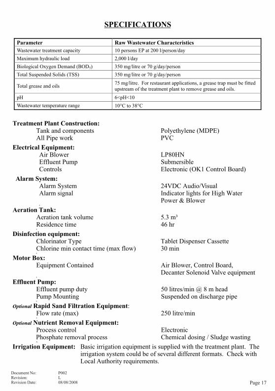
SPECIFICATIONS
Treatment Plant Construction:Tank and components Polyethylene (MDPE)All Pipe work PVC
Electrical Equipment:Air Blower LP80HNEffluent Pump SubmersibleControls Electronic (OK1 Control Board)
Alarm System:Alarm System 24VDC Audio/VisualAlarm signal Indicator lights for High Water
Power & Blowera
Aeration Tank:Aeration tank volume 5.3 m³Residence time 46 hra
Disinfection equipment:Chlorinator Type Tablet Dispenser CassetteChlorine min contact time (max flow) 30 mina
Motor Box:Equipment Contained Air Blower, Control Board,
Decanter Solenoid Valve equipmenta
Effluent Pump:Effluent pump duty 50 litres/min @ 8 m headPump Mounting Suspended on discharge pipea
Optional Rapid Sand Filtration Equipment:Flow rate (max) 250 litre/mina
Optional Nutrient Removal Equipment:Process control ElectronicPhosphate removal process Chemical dosing / Sludge wastingA
Irrigation Equipment: Basic irrigation equipment is supplied with the treatment plant. The irrigation system could be of several different formats. Check with Local Authority requirements.
a
A
Page 17
Parameter Raw Wastewater Characteristics
Wastewater treatment capacity 10 persons EP at 200 l/person/day
Maximum hydraulic load 2,000 l/day
Biological Oxygen Demand (BOD5) 350 mg/litre or 70 g/day/person
Total Suspended Solids (TSS) 350 mg/litre or 70 g/day/person
Total grease and oils 75 mg/litre. For restaurant applications, a grease trap must be fitted upstream of the treatment plant to remove grease and oils.
pH 6<pH<10
Wastewater temperature range 10°C to 38°C
Document No: P002Revision: LRevision Date: 08/08/2008

Page 18
Document No: P002Revision: LRevision Date: 08/08/2008
R
SYSTEM DRAWING
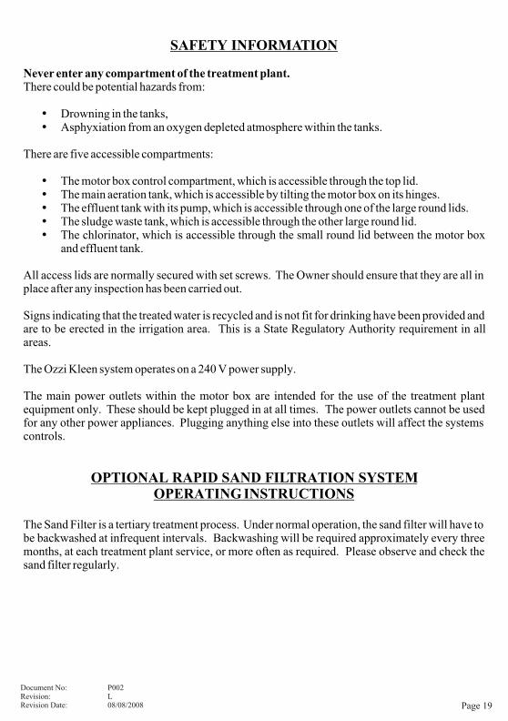
SAFETY INFORMATION
Never enter any compartment of the treatment plant.There could be potential hazards from:
� Drowning in the tanks,� Asphyxiation from an oxygen depleted atmosphere within the tanks.
There are five accessible compartments:
� The motor box control compartment, which is accessible through the top lid.� The main aeration tank, which is accessible by tilting the motor box on its hinges.� The effluent tank with its pump, which is accessible through one of the large round lids.� The sludge waste tank, which is accessible through the other large round lid.� The chlorinator, which is accessible through the small round lid between the motor box
and effluent tank.
All access lids are normally secured with set screws. The Owner should ensure that they are all in place after any inspection has been carried out.
Signs indicating that the treated water is recycled and is not fit for drinking have been provided and are to be erected in the irrigation area. This is a State Regulatory Authority requirement in all areas.
The Ozzi Kleen system operates on a 240 V power supply.
The main power outlets within the motor box are intended for the use of the treatment plant equipment only. These should be kept plugged in at all times. The power outlets cannot be used for any other power appliances. Plugging anything else into these outlets will affect the systems controls.
OPTIONAL RAPID SAND FILTRATION SYSTEMOPERATING INSTRUCTIONS
The Sand Filter is a tertiary treatment process. Under normal operation, the sand filter will have to be backwashed at infrequent intervals. Backwashing will be required approximately every three months, at each treatment plant service, or more often as required. Please observe and check the sand filter regularly.
Page 19
Document No: P002Revision: LRevision Date: 08/08/2008


Please contact your Ozzi Kleen Service Provider with any queries:
Manufactured by: Suncoast Waste Water Management
59 Industrial Avenue, Kunda Park, QLD, 4556
Head Office: 07 5459 4900 Sales: 07 5459 4944 Service: 07 5459 4955
Fax: 07 5456 4677 Email:
www.ozzikleen.com
RP10RP10A
R