Ozgur Ates Hampton University HUGS 2009-JLAB TREK Experiment “Tracking and Baseline Design”
23
Ozgur Ates Hampton University HUGS 2009-JLAB TREK Experiment “Tracking and Baseline Design”
-
Upload
franklin-bumstead -
Category
Documents
-
view
213 -
download
0
Transcript of Ozgur Ates Hampton University HUGS 2009-JLAB TREK Experiment “Tracking and Baseline Design”

Ozgur AtesHampton University
HUGS 2009-JLAB
TREK Experiment“Tracking and Baseline
Design”
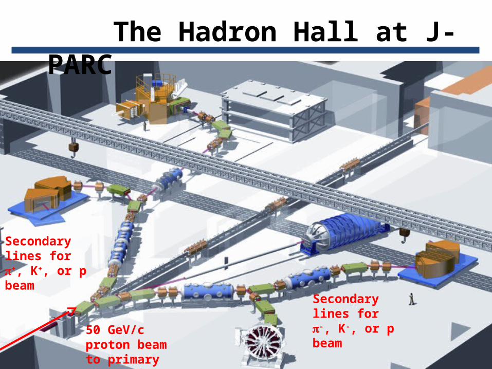
Secondary lines for +, K+, or p beam
50 GeV/c proton beam to primary production target
Secondary lines for -, K-, or p beam
The Hadron Hall at J-PARC
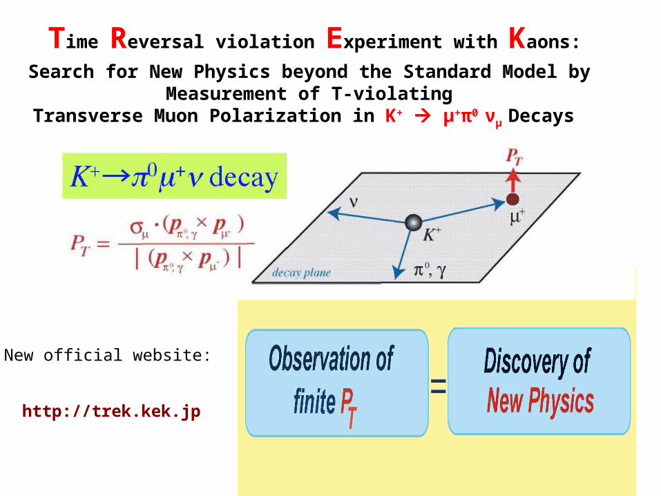
Time Reversal violation Experiment with Kaons:
Search for New Physics beyond the Standard Model by Measurement of T-violating
Transverse Muon Polarization in K+ μ+π0 νμ Decays
New official website:
http://trek.kek.jp

• Planar GEMs “C1” between CsI and C2, or in replacement of C2
• Cylindrical device “C0” in replacement of C1

C1: Planar GEMs for TREK
•“C1” To cover CsI gaps on the outside

Target and Tracking
Better kinematical resolution
Addition of C0 and C1 GEM chambers with- high position resolution - higher rate performance Larger C3-C4
distance
Use of He bags
New target
E246 J-PARC

Upgraded Trek Detector Apparatus


Geant4 Simulation
9
Geant4 studies initiated in Summer 2008
GOALS:
Realistic geometry of upgraded TREK apparatusRealistic tracking performance
Obtain design criteria for
Sizes and locations of new elementsAngular and spatial resolution of tracks at detector elementsWhich spatial detector resolution is adequate?Optimization of material budget
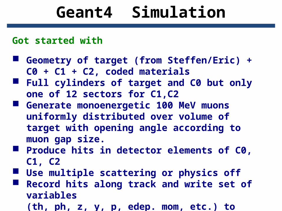
Got started with
Geometry of target (from Steffen/Eric) + C0 + C1 + C2, coded materials
Full cylinders of target and C0 but only one of 12 sectors for C1,C2
Generate monoenergetic 100 MeV muons uniformly distributed over volume of target with opening angle according to muon gap size.
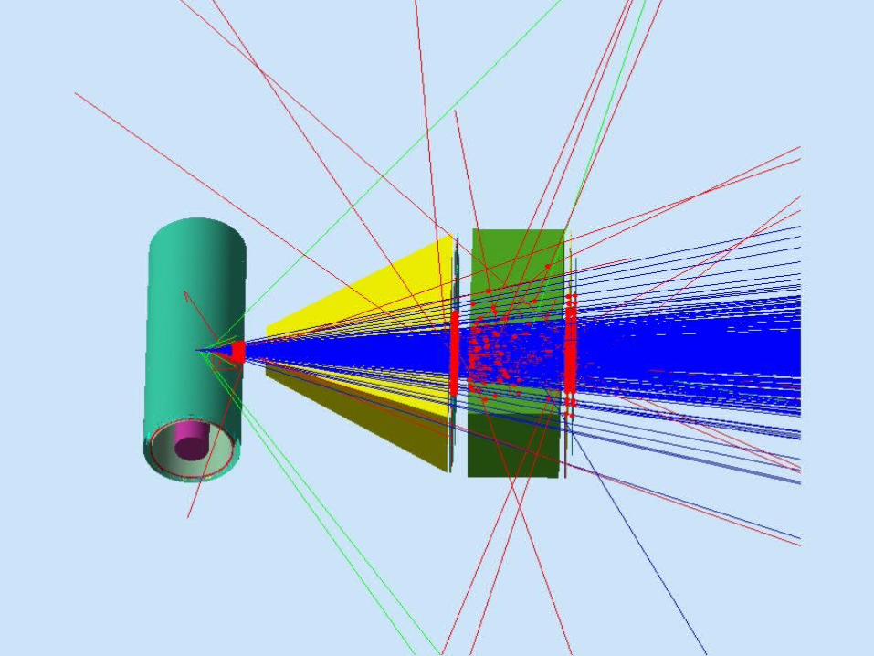
Produce hits in detector elements of C0, C1, C2
Use multiple scattering or physics off Record hits along track and write set of
variables (th, ph, z, y, p, edep. mom, etc.) to ROOT TREE
Geant4 Simulation


Root Analyses
• Studied acceptance of tracks in C0, C1, C2.
•From this study, determined required geometric sizes of C0 and C1.
•Found out that;
•Length of C0 should be: 300 mm•Width of C1 should be: 200 mm•Length of C1 should be: 480 mm

Determination of Length of C0


Determination of Width of C1

Determination of Length of C1

Straight-Line Fit in 3D
• Recorded hit locations of Readout layers of C0, C1 and C2. •Applied straight-line fit in 3D for each generated event.
•Reconstruct straight track from recorded hits with 3D straight-line fit•Recorded fit parameters for each track, and locations of fitted track at each 3 readout layers.
•Closest distance of reconstructed track to origin of generated track (vertex difference)(1st column)•Difference of generated hit position at detectors(C0,C1,C2) and that of the recons. track (2nd to 4th column)

RESIDUALS

Systematic Study of Resolution


Backup Slides•Sanity check: Residuals for Phys=OFF and perfect detectors
•Intrinsic tracking resolution: Explicit Gaussian smearing of hits
•Study effect of physics (MS, Bremss., Ionization, Pairprod. ) separately from intrinsic resolution, use balancing as criterion for design resolution
•studied residuals, i.e. difference of generated and reconstructed hit locations at each readout layer, and at target vertex (closest point with respect to generated vertex)
•studied residuals with and without physics activated in Geant4 (multiple scattering and energy loss)
•concluded lower limits the required intrinsic resolution (<<residual)

High Rate Chamber – Gas Electron Multiplier (GEM) Still Gas Ionization and Avalanche, again, but… A different way to get an intense electric field, Without dealing with fragile tiny wires, and Release + ions much faster
-V
~400v0.002”
GEM
To computer http://gdd.web.cern.ch/GDD/