

Oxygen Sensor - אגרולן · Theory of Operation The SO series are galvanic-cell type sensors...
12
Oxygen Sensor SO-100 & 200 Series
Transcript of Oxygen Sensor - אגרולן · Theory of Operation The SO series are galvanic-cell type sensors...
Oxy
gen
Sen
sor
SO
-100
& 2
00 S
erie
s
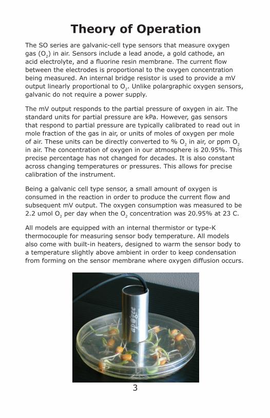
Theory of OperationThe SO series are galvanic-cell type sensors that measure oxygen gas (O2) in air. Sensors include a lead anode, a gold cathode, an acid electrolyte, and a fluorine resin membrane. The current flow between the electrodes is proportional to the oxygen concentration being measured. An internal bridge resistor is used to provide a mV output linearly proportional to O2. Unlike polargraphic oxygen sensors, galvanic do not require a power supply.
The mV output responds to the partial pressure of oxygen in air. The standard units for partial pressure are kPa. However, gas sensors that respond to partial pressure are typically calibrated to read out in mole fraction of the gas in air, or units of moles of oxygen per mole of air. These units can be directly converted to % O2 in air, or ppm O2 in air. The concentration of oxygen in our atmosphere is 20.95%. This precise percentage has not changed for decades. It is also constant across changing temperatures or pressures. This allows for precise calibration of the instrument.
Being a galvanic cell type sensor, a small amount of oxygen is consumed in the reaction in order to produce the current flow and subsequent mV output. The oxygen consumption was measured to be 2.2 umol O2 per day when the O2 concentration was 20.95% at 23 C.
All models are equipped with an internal thermistor or type-K thermocouple for measuring sensor body temperature. All models also come with built-in heaters, designed to warm the sensor body to a temperature slightly above ambient in order to keep condensation from forming on the sensor membrane where oxygen diffusion occurs.
3
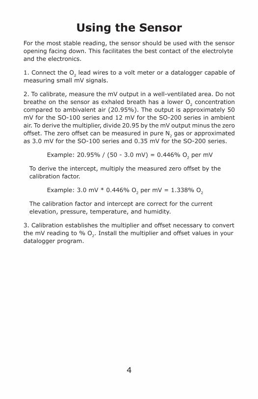
Using the SensorFor the most stable reading, the sensor should be used with the sensor opening facing down. This facilitates the best contact of the electrolyte and the electronics.
1. Connect the O2 lead wires to a volt meter or a datalogger capable of measuring small mV signals.
2. To calibrate, measure the mV output in a well-ventilated area. Do not breathe on the sensor as exhaled breath has a lower O2 concentration compared to ambivalent air (20.95%). The output is approximately 50 mV for the SO-100 series and 12 mV for the SO-200 series in ambient air. To derive the multiplier, divide 20.95 by the mV output minus the zero offset. The zero offset can be measured in pure N2 gas or approximated as 3.0 mV for the SO-100 series and 0.35 mV for the SO-200 series.
Example: 20.95% / (50 - 3.0 mV) = 0.446% O2 per mV
To derive the intercept, multiply the measured zero offset by the calibration factor.
Example: 3.0 mV * 0.446% O2 per mV = 1.338% O2
The calibration factor and intercept are correct for the current elevation, pressure, temperature, and humidity.
3. Calibration establishes the multiplier and offset necessary to convert the mV reading to % O2. Install the multiplier and offset values in your datalogger program.
4
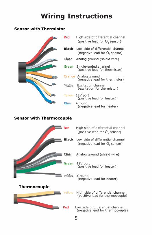
Wiring Instructions
Red High side of differential channel (positive lead for O2 sensor)
Black Low side of differential channel (negative lead for O2 sensor)
Analog ground (shield wire)
Green Single-ended channel (positive lead for thermistor)
Orange Analog ground (negative lead for thermistor)
White Excitation channel (excitation for thermistor)
Yellow 12V port (positive lead for heater)
Blue Ground (negative lead for heater)
Sensor with Thermistor
Yellow High side of differential channel (positive lead for thermocouple)
Red Low side of differential channel (negative lead for thermocouple)
Thermocouple
Red High side of differential channel (positive lead for O2 sensor)
Green 12V port (positive lead for heater)
White Ground (negative lead for heater)
Sensor with Thermocouple
Black Low side of differential channel (negative lead for O2 sensor)
Analog ground (shield wire)
5
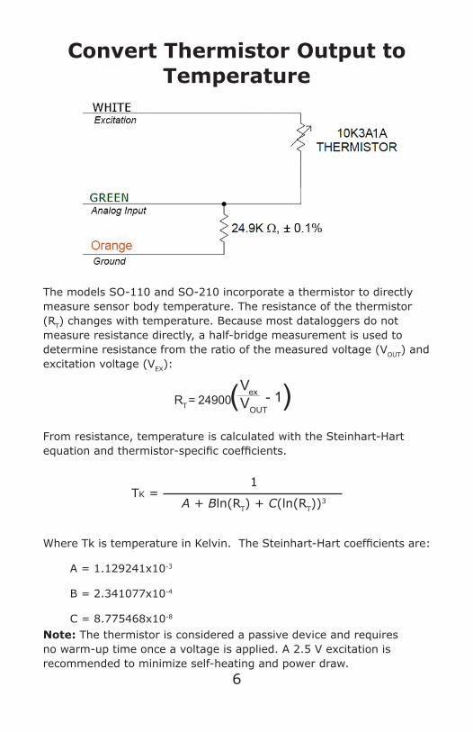
Convert Thermistor Output to Temperature
VexVOUT
RT = 24900 ( )- 1
From resistance, temperature is calculated with the Steinhart-Hart equation and thermistor-specific coefficients.
Tk =1
A + Bln(RT) + C(ln(RT))3
Where Tk is temperature in Kelvin. The Steinhart-Hart coefficients are:
A = 1.129241x10⁻³
B = 2.341077x10⁻⁴
C = 8.775468x10⁻⁸
The models SO-110 and SO-210 incorporate a thermistor to directly measure sensor body temperature. The resistance of the thermistor (RT) changes with temperature. Because most dataloggers do not measure resistance directly, a half-bridge measurement is used to determine resistance from the ratio of the measured voltage (VOUT) and excitation voltage (VEX):
Note: The thermistor is considered a passive device and requires no warm-up time once a voltage is applied. A 2.5 V excitation is recommended to minimize self-heating and power draw.
6
CharacteristicsZero OffsetThe mV output in ultra-pure nitrogen gas (0.000% O2) is typically 6% of the ambient (20.95%) output for the SO-100 series and 3% of the ambient output for the SO-200 series. Precise measurements of hypoxic and anaerobic conditions can be made by making a periodic zero calibration of the sensor with ultra-pure nitrogen gas.
Life ExpectancyThe life expectancy of the sensor is expressed in %-years as follows:
[Oxygen Concentration (%) * Exposure Time (years)]
The life of the SO-100 series is approximately 10 years of continuous use at 21% oxygen and 20 C. Under the same conditions the life of the SO-200 series is approximately 5 years.
Storage TemperatureThe life of the sensor can be extended by storage at a lower temperature. For example, a sensor stored at 0 C will have a life expectancy approximately twice that of a sensor stored at 20 C. The minimum storage temperature is -20 C. Below -20 C, the electrolyte will freeze. This does not damage the sensor, but to resume measurement the electrolyte must be thawed. Maximum storage temperature is 60 C.
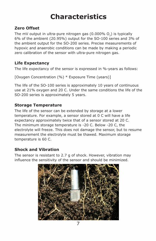
Shock and VibrationThe sensor is resistant to 2.7 g of shock. However, vibration may influence the sensitivity of the sensor and should be minimized.
7
8
Factors Affecting OutputInfluence from Various GasesThe sensor is unaffected by CO, CO2, NO, NO2, H2S, H2, and CH4. There is a small effect (approximately 1%) from NH3, HCI, and C6H6 (benzene). The sensor is sensitive to SO2 and can be damaged by O3.
Temperature SensitivityA change in temperature changes the amount of O2 available to the sensor and therefore changes the mV output that correlates to the atmospheric constant of 20.95%. Additionally, the sensor electronics have a small temperature dependence. To eliminate temperature effects, simply recalibrate or use the correction equations detailed in the write-up, “Understanding Oxygen in Air”, located in the Knowledge Base of the Apogee website.
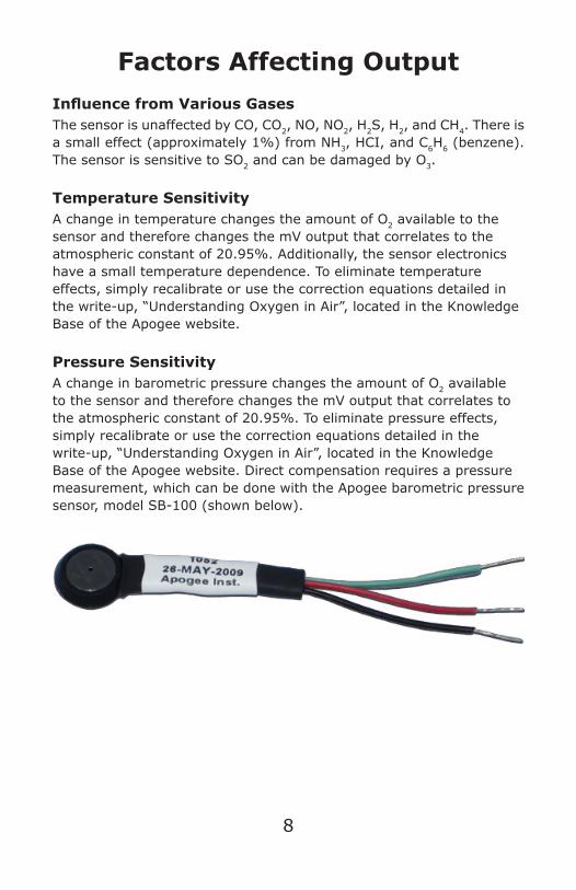
Pressure SensitivityA change in barometric pressure changes the amount of O2 available to the sensor and therefore changes the mV output that correlates to the atmospheric constant of 20.95%. To eliminate pressure effects, simply recalibrate or use the correction equations detailed in the write-up, “Understanding Oxygen in Air”, located in the Knowledge Base of the Apogee website. Direct compensation requires a pressure measurement, which can be done with the Apogee barometric pressure sensor, model SB-100 (shown below).
9
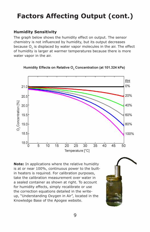
Humidity SensitivityThe graph below shows the humidity effect on output. The sensor chemistry is not influenced by humidity, but its output decreases because O2 is displaced by water vapor molecules in the air. The effect of humidity is larger at warmer temperatures because there is more water vapor in the air.
Note: In applications where the relative humidity is at or near 100%, continuous power to the built-in heaters is required. For calibration purposes, take the calibration measurement over water in a sealed container as shown at right. To account for humidity effects, simply recalibrate or use the correction equations detailed in the write-up, “Understanding Oxygen in Air”, located in the Knowledge Base of the Apogee website.
Factors Affecting Output (cont.)
Accessories
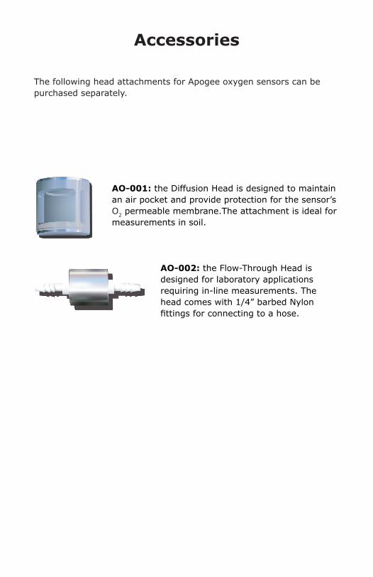
AO-001: the Diffusion Head is designed to maintain an air pocket and provide protection for the sensor’s O2 permeable membrane.The attachment is ideal for measurements in soil.
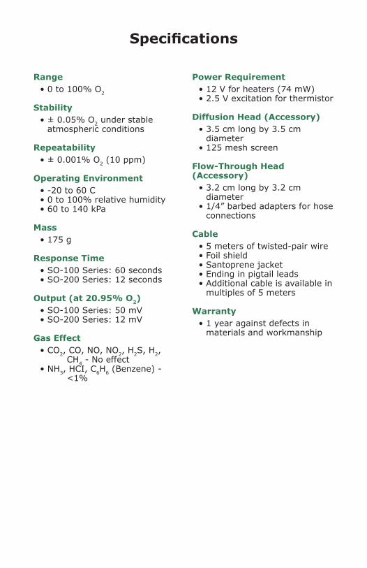
AO-002: the Flow-Through Head is designed for laboratory applications requiring in-line measurements. The head comes with 1/4” barbed Nylon fittings for connecting to a hose.
The following head attachments for Apogee oxygen sensors can be purchased separately.
Range• 0 to 100% O2
Stability• ± 0.05% O2 under stable
atmospheric conditions
Repeatability• ± 0.001% O2 (10 ppm)
Operating Environment• -20 to 60 C• 0 to 100% relative humidity• 60 to 140 kPa
Mass• 175 g
Response Time• SO-100 Series: 60 seconds• SO-200 Series: 12 seconds
Output (at 20.95% O2)• SO-100 Series: 50 mV• SO-200 Series: 12 mV
Gas Effect• CO2, CO, NO, NO2, H2S, H2,
CH4 - No effect• NH3, HCI, C6H6 (Benzene) -
<1%
Specifications
Power Requirement• 12 V for heaters (74 mW)• 2.5 V excitation for thermistor
Diffusion Head (Accessory)• 3.5 cm long by 3.5 cm
diameter• 125 mesh screen
Flow-Through Head (Accessory)
• 3.2 cm long by 3.2 cm diameter
• 1/4” barbed adapters for hose connections
Cable• 5 meters of twisted-pair wire• Foil shield• Santoprene jacket• Ending in pigtail leads• Additional cable is available in
multiples of 5 meters
Warranty• 1 year against defects in
materials and workmanship