oxygen (LO2)/liquid methane (LCH4) Integrated … Institute of Aeronautics and Astronautics 092407 1...
14
In support of NASA’s former Propulsion and Cryogenic Advanced Development (PCAD) project, a liquid oxygen (LO 2 )/liquid methane (LCH 4 ) Integrated Propulsion System Test Bed (IPSTB) was conceived, designed, and advanced to the Critical Design Review (CDR) stage at the Johnson Space Center. The IPSTB’s primary objective is to study LO 2 /LCH 4 propulsion system steady state and transient performance, operational characteristics and to validate computer models of a LO2/LCH4 propulsion system for use in future flight design work. The baseline configuration was designed to accommodate one 6,050 lbf main engine, four 100 lbf reaction control engines (RCE’s), and several cold flow simulators providing flow rates representative of 25 to 200 lbf thrusters. The IPSTB feed system includes four ground based, spherical propellants tanks capable of supporting up to 240 seconds of main engine firing and simultaneous RCE profiles, four RCE pods housing the RCE engines and simulators, and a Thermodynamic Vent System (TVS) for thermal conditioning of the lines and tanks. Additionally, a liquid nitrogen/liquid methane heat exchanger, to be used in conjunction with the TVS and aerogel insulation, were planned to give the system the capability to deliver densified/sub-cooled cryogenic methane to the engine inlets. Figure 1 Two phase thermal and dynamic fluid flow models of the IPSTB were built to predict the system performance characteristics under a variety of operating modes and to aid in the overall system design work. While at ambient temperature and simulated altitude conditions at the White Sands Test Facility, the IPSTB and its approximately 600 channels of system instrumentation would be operated to perform a variety of integrated main engine and RCE hot fire tests. The pressure, temperature, and flow rate data collected during this testing would then be used to validate the analytical models of the IPSTB’s https://ntrs.nasa.gov/search.jsp?R=20110012829 2018-07-11T14:09:20+00:00Z
Transcript of oxygen (LO2)/liquid methane (LCH4) Integrated … Institute of Aeronautics and Astronautics 092407 1...

In support of NASA’s former Propulsion and Cryogenic Advanced Development (PCAD) project, a liquid oxygen (LO2)/liquid methane (LCH4) Integrated Propulsion System Test Bed (IPSTB) was conceived, designed, and advanced to the Critical Design Review (CDR) stage at the Johnson Space Center.
The IPSTB’s primary objective is to study LO2/LCH4 propulsion system steady state and transient performance, operational characteristics and to validate computer models of a LO2/LCH4 propulsion system for use in future flight design work.
The baseline configuration was designed to accommodate one 6,050 lbf main engine, four 100 lbf reaction control engines (RCE’s), and several cold flow simulators providing flow rates representative of 25 to 200 lbf thrusters. The IPSTB feed system includes four ground based, spherical propellants tanks capable of supporting up to 240 seconds of main engine firing and simultaneous RCE profiles, four RCE pods housing the RCE engines and simulators, and a Thermodynamic Vent System (TVS) for thermal conditioning of the lines and tanks. Additionally, a liquid nitrogen/liquid methane heat exchanger, to be used in conjunction with the TVS and aerogel insulation, were planned to give the system the capability to deliver densified/sub-cooled cryogenic methane to the engine inlets.
Figure 1
Two phase thermal and dynamic fluid flow models of the IPSTB were built to predict the system performance characteristics under a variety of operating modes and to aid in the overall system design work. While at ambient temperature and simulated altitude conditions at the White Sands Test Facility, the IPSTB and its approximately 600 channels of system instrumentation would be operated to perform a variety of integrated main engine and RCE hot fire tests. The pressure, temperature, and flow rate data collected during this testing would then be used to validate the analytical models of the IPSTB’s
https://ntrs.nasa.gov/search.jsp?R=20110012829 2018-07-11T14:09:20+00:00Z

thermal and dynamic fluid flow performance. An overview of the IPSTB design and analytical model development will be presented.

American Institute of Aeronautics and Astronautics
092407
1
Liquid Oxygen / Liquid Methane Integrated Propulsion System Test Bed
Howard Flynn NASA - Lyndon B. Johnson Space Center, Houston, Texas, 77058
Brian Lusby NASA - Lyndon B. Johnson Space Center, Houston, Texas, 77058
In support of NASA’s Propulsion and Cryogenic Advanced Development (PCAD) project, a liquid oxygen (LO2)/liquid methane (LCH4) Integrated Propulsion System Test Bed (IPSTB) was designed and advanced to the Critical Design Review (CDR) stage at the Johnson Space Center. The IPSTB’s primary objectives are to study LO2/LCH4 propulsion system steady state and transient performance, operational characteristics and to validate fluid and thermal models of a LO2/LCH4 propulsion system for use in future flight design work. Two phase thermal and dynamic fluid flow models of the IPSTB were built to predict the system performance characteristics under a variety of operating modes and to aid in the overall system design work. While at ambient temperature and simulated altitude conditions at the White Sands Test Facility, the IPSTB and its approximately 600 channels of system instrumentation would be operated to perform a variety of integrated main engine and reaction control engine hot fire tests. The pressure, temperature, and flow rate data collected during this testing would then be used to validate the analytical models of the IPSTB’s thermal and dynamic fluid flow performance. An overview of the IPSTB design and analytical model development will be presented.
Nomenclature AME = Ascent Main Engine ASME = American Society of Mechanical Engineers CDR = critical design review CTFE = chlorotrifluoroethylene ECLSS = Environmental Control and Life Support Systems GHe = gaseous helium GN2 = gaseous nitrogen IPSTB = Integrated Propulsion System Test Bed ISRU = in-situ resource utilization lbf = pound force lbm = pound mass LCH4 = liquid methane LN2 = liquid nitrogen LO2 = liquid oxygen MAWP = maximum allowable working pressure PLRD = project level requirements document PSIA = pounds per square inch absolute PSIG = pounds per square inch gauge PTFE = polytetraflouroethylene RCE = reaction control engine TRL = technology readiness level TS-401 = test stand 401 WSTF = White Sands Test Facility

American Institute of Aeronautics and Astronautics
092407
2
I. Introduction
In recent years, NASA has performed significant work to investigate the use of advanced cryogenic propellants (LO2, LCH4, LH2) to be used for in-space orbital maneuvering, reaction and control, and lander descent/ascent propulsion systems. Compared to current state of the art earth storable propellants, they offer the advantage of increased performance, can be integrated with other spacecraft subsystems, such as power and ECLSS, and are much easier to work because they are non-toxic.
Of specific interest at the Johnson Space Center for on-orbit and lander propulsion systems is the use of cryogenic LO2/LCH4. While no propellant combination is ideal for all applications, LO2/LCH4 offers a number of advantages compared to other candidate in-space propellants:
• High vehicle performance (Isp) • Clean burning with no residue • Long duration storability • Commonality with other spacecraft subsystem fluids (fuel cell power, ECLSS) • Compatibility with Lunar and Mars ISRU propellant manufacturing technologies
And while much work has been done to increase the technology readiness level of the feed system and thruster
components that make up a LO2/LCH4 propulsion system, less work has been done to study, characterize and model the integrated operation of those components in an end to end propulsion system. The IPSTB was conceived with this purpose in mind.
Its primary objectives include designing, assembling and testing a LO2/LCH4 propulsion system to understand its transient and steady state performance, operational characteristics and to validate computer models of a LO2/LCH4 propulsion system for use in flight design work. Secondary objectives include:
• Demonstrating a successful up-firing RCS engine • Demonstrating reliable simultaneous RCS and main engine hot-fire tests running conceptual mission
duty cycles • Gaining understanding of any potential interactions between RCS engines and main engine • Providing ground test data pertinent to the Altair and Orion projects regarding the use of Lox/LCH4
propellants
II. IPSTB Description The baseline IPSTB configuration design is a ground based, modular representation of a pressure fed Lox/LCH4
propulsion system for a conceptual lunar ascent stage. Four insulated, spherical propellant tanks are pressurized with facility provided GHe and feed one 6,050 lbf main engine, up to four 100 lbf reaction control engines (RCE’s), and up to four cold flow simulators providing flow rates representative of 25 to 200 lbf thrusters. Commercial cryogenic valves and actuators are used throughout the IPSTB and all lines and tanks are insulated with CryogelTM insulation of varying thicknesses. The modularity of the design allows for alternate propulsion stage configurations including the use of a main engine with a vacuum thrust rating of up to 10,000 lbf. The IPSTB is designed for installation into the WSTF test stand 401 where it will be used to perform a variety of RCS hot fires and cold flows combined with main engine hot fire tests as an integrated system and at a simulated altitude of 70,000 to 100,000 feet and ambient temperature. Operating pressure is 450 psig and MAWP for system is 515 psig. Primary insulating material is Cryogel-Z.
System wetted metal materials for tanks, fittings, tubing, valves and flanges are limited to 304 and 316 stainless
steel (L version when welded), 17-4PH stainless steel for PTFE coated Grayloc seals, and copper nose seals in AN fittings and VCR fitting gaskets. Wetted non-metallic materials are limited to Teflon/PTFE and CTFE

American Institute of Aeronautics and Astronautics
092407
3
Figure 1 The IPSTB feed system starts with four 50” diameter, thermally insulated propellants tanks of the same type – 2
for Lox and 2 for fuel. All four tanks are identical in design to reduce procurement costs and the tanks are plumbed in parallel pairs but can accommodate series flow with a bolt-on modification. Tank material is 304/304L stainless steel and the vessels are ASME pressure vessel compliant. Each tank has an internal volume of 36 ft3, an MAWP of 515 psig and provides a minimum usable propellant storage volume capability of 21ft3 after accounting for ullage volume, test operating limits and additional margin. At the densest propellant conditions anticipated, the total propellant available for tests is 1,900 lbm liquid methane and 5,000 lbm Lox which meets the IPSTB’s requirement for 240 seconds of main engine and RCE firings.
Figure 2

American Institute of Aeronautics and Astronautics
092407
4
Incorporated within each tank are two level sensor probes for determining tank propellant level, a vortex
preventer to mitigate ingestion of pressurant gas into the engine feedlines, various pressure/temperature instrumentation ports, a propellant outlet, and a GHe pressurant inlet. The outlet of each tank is oversized to allow changeout of the tank’s vortex preventer, provide access to the tank’s interior for cleaning and instrumentation installation and to accommodate the use of a 10,000 lbf main engine.
A motor operated, proportionally controlled cryogenic tank isolation valve isolates each propellant tank and is
located just downstream of the outlet of each tank. Valve proportional control allows the capability to offset any imbalanced flow within a propellant tank pair during engine firings. The outlet of each tank isolation valve feeds either the Lox or LCH4 propellant manifold which then feeds the main engine and four RCE pods. Great care was taken in the design to eliminate/reduce pressure drop from the propellant tanks to the main engine and RCE inlets and in order to meet the IPSTB design requirement of < XX psi from tank outlet to engine inlet.
Figure XX All cryogenic propellant fluid lines are 304L or 316L stainless steel tubing. Valves will be attached to structure
with thermally insulated brackets and welded joints will be used where field-joints are not required. Where field joints are required, VCR or AN fittings with nose seals will be used with the exception of the tank to tube interface which will use a Grayloc connector.
The IPSTB feedsystem supplies propellant to the main engine through two pneumatically operated manifold
isolation valves – one for oxidizer and one for fuel. Downstream of each valve is a turbine and venturi flowmeter for measuring steady state and transient propellant flow rates during main engine operation. The main engine is hard mounted to the IPSTB main engine welded structure which is bolted to the IPSTB bridge structure. This design allows access clearance above the injector for the engine ignition electronics, plumbing and instrumentation and can be removed to accommodate alternate main engine configurations. No thruster measurement capability is currently provided as it was envisioned that this measurement would be performed during main engine thruster testing prior to integrated IPSTB testing. Flow rate and chamber pressure readings during IPSTB main engine firings could be used to estimate main engine thrust if necessary.
American Institute of Aeronautics and Astronautics
092407
5
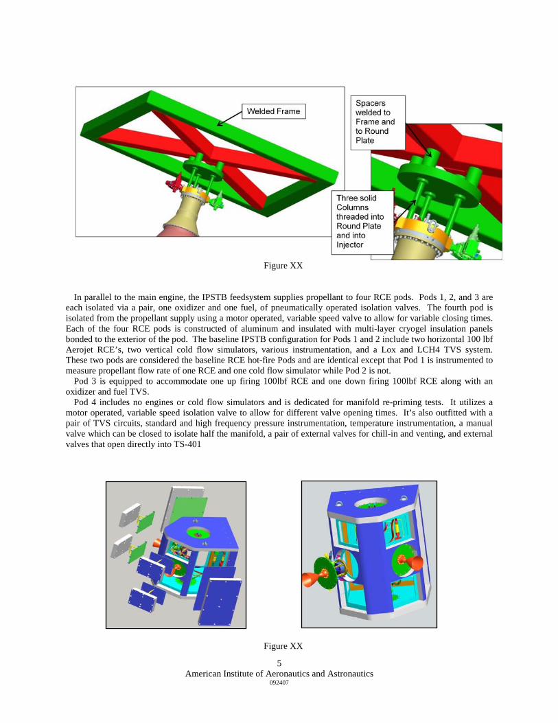
Figure XX
In parallel to the main engine, the IPSTB feedsystem supplies propellant to four RCE pods. Pods 1, 2, and 3 are
each isolated via a pair, one oxidizer and one fuel, of pneumatically operated isolation valves. The fourth pod is isolated from the propellant supply using a motor operated, variable speed valve to allow for variable closing times. Each of the four RCE pods is constructed of aluminum and insulated with multi-layer cryogel insulation panels bonded to the exterior of the pod. The baseline IPSTB configuration for Pods 1 and 2 include two horizontal 100 lbf Aerojet RCE’s, two vertical cold flow simulators, various instrumentation, and a Lox and LCH4 TVS system. These two pods are considered the baseline RCE hot-fire Pods and are identical except that Pod 1 is instrumented to measure propellant flow rate of one RCE and one cold flow simulator while Pod 2 is not.
Pod 3 is equipped to accommodate one up firing 100lbf RCE and one down firing 100lbf RCE along with an oxidizer and fuel TVS.
Pod 4 includes no engines or cold flow simulators and is dedicated for manifold re-priming tests. It utilizes a motor operated, variable speed isolation valve to allow for different valve opening times. It’s also outfitted with a pair of TVS circuits, standard and high frequency pressure instrumentation, temperature instrumentation, a manual valve which can be closed to isolate half the manifold, a pair of external valves for chill-in and venting, and external valves that open directly into TS-401
Figure XX

American Institute of Aeronautics and Astronautics
092407
6
The IPSTB structural design consists of 4 major subassemblies – the bridge, the core, the main engine mount and the RCE support. All four assemblies use hollow, box section structural steel beams varying in size from 6” x 12” x 3/8” (bridge beams) to 6” x 6” x ¼” (core, main engine thrust frame) to 4” x 4” x 1/4” (RCS pod supports). In order to meet requirements for alternate configurations, bolted joints connect the welded sub-assemblies to one another.
Requirements for the IPSTB structural capability include an unlimited number of 200 lbf RCE pulses at up to
6.25 Hz and five thousand 10,000 lbf main engine firings. Finite element analysis of the major structural components was performed to confirm the structure lowest frequency is greater than 9Hz (14.8 Hz) and that all analyzed parts and assemblies have positive margins with respect to required factors of safety.

American Institute of Aeronautics and Astronautics
092407
7
Figure XX
Figure XX The bridge structure is an all welded assembly and carries the weight of the entire IPSTB which has a maximum
weight requirement of no more than 36,000 lbs when fully loaded with propellant. Four support pads incorporating ball and socket assemblies and welded to the bridge are clamped to the WSTF facility’s Western Gear lift for raising and lowering the IPSTB within the test stand.
Figure XX Bridge Structure
The core structure is bolted to the top of the bridge sub-assembly and carries the weight of the propellant tanks,
RCS pods and plumbing. The lower x-box and vertical corner posts are one welded assembly while the top and center x-boxes are bolted in to facilitate propellant tank change-out. The four propellant tanks are each suspended from either the central or upper x-boxes with a U-joint assembly bolted to a structural attach flange on the top of each tank. An upper strut, a torsion control strut, an x-axis strut and a y- axis strut provide lateral and torsional support to the tanks and increase the natural frequency of the tank/structure system to prevent low frequency coupling.

American Institute of Aeronautics and Astronautics
092407
8
The IPSTB thermal control system is required to condition and maintain the IPSTB propellants between 275 and
375 psia, 163 R and 224R for Lox, 170 R and 224 R for LCH4, and provide a temperature increase of no more than 10oF from the propellant tanks to the engine valve inlets. To do this, the system consists of passive insulation overwrapping the system tanks, piping and components to minimize system heat leak and an active cooling loop, known as the TVS, to maintain propellant temperatures after initial chill-in of the system. The insulation and TVS systems are sized to an ambient pressure ranging from 5 torr to 760 torr and an environment temperature of 100F. Additional active cooling via a facility provided LN2 heat exchanger will be required to reach the IPSTB project minimum temperature requirement of 170 R since the LCH4 saturation pressure at ambient pressure is 197 R.
System initial chill-in requires approx 550 lbs of LCh4 for the methane propellant tanks and approx 1500 lbs of
Lox for the oxygen tanks plus another approximately 200 lbs of propellant required for the system lines, fittings and components. Estimates of the propellant hold time/prediction of boil-off have also been performed and show acceptable passive system thermal performance (i.e. insulation thickness).
Once initially temperature conditioned, the IPSTB tanks, components and lines utilize the TVS to remove heat
from the fluid system and maintain propellant temperatures before and between engine firings. The TVS lines are brazed to the propellant tanks and lines and clamped or thermally epoxied to system components to provide a conduction path for cooling. The TVS operates by expanding small amounts of Lox or LCh4 propellant, supplied from the IPSTB propellant tanks, through an orifice to an ambient pressure ranging from 12.4 psia to 5 torr. The TVS is sized to maintain the coldest expected propellant temperatures at environmental temperatures up to 100F and atmospheric pressure between 12.4 psia and 5 torr. It consists of fourteen individually controlled TVS circuits, seven Lox and seven LCh4, with a user defined set-pt and dead-band. Each circuit consists of a controller, tubing, valve and orifice and each controller cycles a valve open/closed to start stop TVS flow in its zone/circuit. Thermal analysis of TVS performance at 12.4 psia (WSTF ambient pressure) shows that vacuum eduction of the TVS outlets is required to maintain propellant temperatures at the lower end of the required ranges. Additional LN2 cooling may be required to maintain LCH4 temperatures below 185F.

American Institute of Aeronautics and Astronautics
092407
9
Figure XX 14 independent TVS circuits (7 Lox and 7 LCH4) are planned for the IPSTB design and are designed to operate at
test stand pressures from 12.4 psia (WSTF ambient) to 5 torr. Each circuit contains its own temperature control system (controller and temp sensor) and cycles a valve open or closed automatically based on the sensed temperature. TVS operation is required for use pre-test, between tests, during tests, and during cold soaks and chill-in periods. TVS sizing computations predict that the TVS can maintain a TIR < 10 R from tanks to engines if the tanks temperatures are higher than 180R for Lox and 220R for LCh4 with ambient TVS operation. To keep the TIR < 10R, vacuum educators must be included in the design to lower the TVS temperature low tank temperature tests. The LCH4 TVS vent loop [ressure needs to be reduced down to 95 torr (1.8 psia at 165R) or 165 torr (3.2 psia at 140 R) for Lox.
Since the primary objective of the IPSTB is to validate the analytical models of the IPSTB’s thermal and dynamic
fluid flow performance, the IPSTB design is heavily instrumented. A total of 603 analog channels of instrumentation are planned for the IPSTB with 558 measurements dedicated to the test article along with another 45 channels planned for the WSTF test facility to safely operate the IPSTB. See table XX for a breakdown of the test article instrumentation.

American Institute of Aeronautics and Astronautics
092407
10
Table XX
III. Modeling Activity
Two physics based analytical tools, an EASY5 fluids only model and a Sinda/Fluint thermodynamics model,
were built to assess the IPSTB’s thermodynamic and fluid system characteristics before, during and after IPSTB testing. These models were also used to help determine the IPSTB instrumentation requirements for model validation. The use of these models included pre-test analytical support to assess steady state pressure drop predictions, water hammer peak pressure and time predictions, transient pressure droop, environment heat loads, insulation performance, TVS flowrate and orifice requirements, system propellant temperature deltas and verify the feasibility of planned operations. During testing, the models will be used to compare test results with pre-test predictions. Post test use of the models will include correlation and validation with the test data to provide guidance for follow on testing configurations.
A two phase, one dimensional flow EASY5 fluid model of the IPSTB was built to assess the steady state and
transient flow characteristics of the system. EASY5 is a general mathematical engineering tool that provides time and frequency domain analyses. The 3-D Pro/E model of the IPSTB was used to develop the fluid model and determine line lengths, valve positions, line bends, height changes, etc. Validation of the model’s components was performed using previous Lox/LCH4 engine test data. Steady state models of the IPSTB were generated for both propellant feed systems and these models were then modified to provide transient analysis capability. For both steady state and transient analyses, two sets of initial propellant conditions were used.
POD 1 POD 2 POD 3 POD 4 LOX TANKS FUEL TANKS LOX TVS FUEL TVS MAIN ENG TOTALS
Accels and Dynamic Pressures 7 7
Delta Pressures (for Venturi measurements)
4 3 7
Valve Currents 8 8 4 7 27
Voltage measurements 8 8 8 8 32
High Level Pressures 6 6 6 2 2 4 4 7 37
Bridge Pressures 20 14 10 10 7 7 2 2 16 88
Thermocouple temperatures 9 8 8 2 26 53
RTD Temperatures 8 6 4 8 32 32 5 95
Silicon Diode Temperatures 16 14 12 8 7 11 7 7 82
Pyrometer Temperatures 6 6 6 2 20
Position Measurements 2 10 10 22
Mass Flow Rate Measurements 1 1 2 2 6
Volume Flow Measurements 2 2
Allocated Spares 8 8 8 24
Allocated Strain Gage Channels 56
Total Analog Channel Count: 558

American Institute of Aeronautics and Astronautics
092407
11
Figure XX EASY5 Fuel Top Level Model Schematic
Cases specifically modeled with EASY5 include the system steady state flow and pressure drop of various
engine firing combinations, the system start-up and shutdown transients assuming main engine operation only, single RCE operation only, single cold flow simulator operation only and a combination of main engine, RCE and cold flow simulator operation with varying duty cycles. Of specific interest, is the IPSTB feedsystem’s capability to meet requirements for total pressure drop from tank to engine for RCE and main engine firing scenarios. Additionally, the system natural frequencies were determined to assess possible coupling between the planned RCE duty cycles and the system .
A one dimensional flow Sinda/Fluint model made up of approximately 3,000 fluid nodes and more than 96,000
thermal nodes was also developed to assess the thermodynamic and steady state fluid characteristics of the system. The model geometry is based on the Pro/E model of the IPSTB and is capable of characterizing single phase compressible liquids as well as 2 phase and supercritical fluid flow with built in external thermal environments. Data from 100 lbf RCE and AME testing performed at WSTF was used to characterize engine performance within the model.

American Institute of Aeronautics and Astronautics
092407
12
Figure XX Sinda/Fluint Model
The Sinda/Fluint model characterized the steady state system pressure drop from tank to engine inlet for
numerous cases of engine hot fires and cold flows operating under various propellant tank conditions, the quiescent system temperature rise and system temperature deltas, and TVS performance. All steady state cases operated as expected though some steady state pressure drop reconciliation work between the EASY5 and Sinda/Fluint model activity remains to be performed.