OXFORD CAMBRIDGE AND RSA EXAMINATIONS ...mei.org.uk/files/papers/m206ju_rw67.pdfOXFORD CAMBRIDGE AND...
14
This question paper consists of 6 printed pages and 2 blank pages. OXFORD CAMBRIDGE AND RSA EXAMINATIONS Advanced Subsidiary General Certificate of Education Advanced General Certificate of Education MEI STRUCTURED MATHEMATICS 4762 Mechanics 2 Monday 19 JUNE 2006 Morning 1 hour 30 minutes Additional materials: 8 page answer booklet Graph paper MEI Examination Formulae and Tables (MF2) TIME 1 hour 30 minutes INSTRUCTIONS TO CANDIDATES • Write your name, centre number and candidate number in the spaces provided on the answer booklet. • Answer all the questions. • You are permitted to use a graphical calculator in this paper. • Final answers should be given to a degree of accuracy appropriate to the context. • The acceleration due to gravity is denoted by g ms –2 . Unless otherwise instructed, when a numerical value is needed, use g = 9.8. INFORMATION FOR CANDIDATES • The number of marks is given in brackets [ ] at the end of each question or part question. • You are advised that an answer may receive no marks unless you show sufficient detail of the working to indicate that a correct method is being used. • The total number of marks for this paper is 72. HN/4 © OCR 2006 [A/102/2654] Registered Charity 1066969 [Turn over
Transcript of OXFORD CAMBRIDGE AND RSA EXAMINATIONS ...mei.org.uk/files/papers/m206ju_rw67.pdfOXFORD CAMBRIDGE AND...
This question paper consists of 6 printed pages and 2 blank pages.
OXFORD CAMBRIDGE AND RSA EXAMINATIONS
Advanced Subsidiary General Certificate of EducationAdvanced General Certificate of Education
MEI STRUCTURED MATHEMATICS 4762Mechanics 2
Monday 19 JUNE 2006 Morning 1 hour 30 minutes
Additional materials:8 page answer bookletGraph paperMEI Examination Formulae and Tables (MF2)
TIME 1 hour 30 minutes
INSTRUCTIONS TO CANDIDATES
• Write your name, centre number and candidate number in the spaces provided on the answerbooklet.
• Answer all the questions.
• You are permitted to use a graphical calculator in this paper.
• Final answers should be given to a degree of accuracy appropriate to the context.
• The acceleration due to gravity is denoted by g m s–2. Unless otherwise instructed, when anumerical value is needed, use g = 9.8.
INFORMATION FOR CANDIDATES
• The number of marks is given in brackets [ ] at the end of each question or part question.
• You are advised that an answer may receive no marks unless you show sufficient detail of theworking to indicate that a correct method is being used.
• The total number of marks for this paper is 72.
HN/4© OCR 2006 [A/102/2654] Registered Charity 1066969 [Turn over
4762 June 2006 [Turn over
3
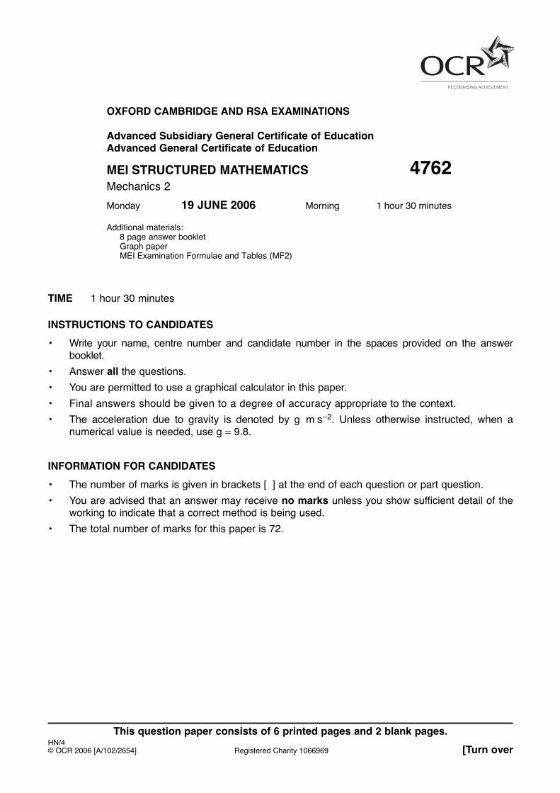
1 (a) Two small spheres, P of mass 2 kg and Q of mass 6 kg, are moving in the same straight linealong a smooth, horizontal plane with the velocities shown in Fig. 1.1.
Fig. 1.1
Consider the direct collision of P and Q in the following two cases.
(i) The spheres coalesce on collision.
(A) Calculate the common velocity of the spheres after the collision. [3]
(B) Calculate the energy lost in the collision. [2]
(ii) The spheres rebound with a coefficient of restitution of in the collision.
(A) Calculate the velocities of P and Q after the collision. [6]
(B) Calculate the impulse on P in the collision. [2]
(b) A small ball bounces off a smooth, horizontal plane. The ball hits the plane with a speed of
at an angle of to it. The ball rebounds at an angle of to the plane, as
shown in Fig. 1.2.
Fig. 1.2
Calculate the speed with which the ball rebounds from the plane.
Calculate also the coefficient of restitution in the impact. [6]
arcsin 1213 arcsin 3
5
arcsin 35arcsin 121326 m s–1
23
Q6kg
2ms–1
P2kg
4ms–1
4
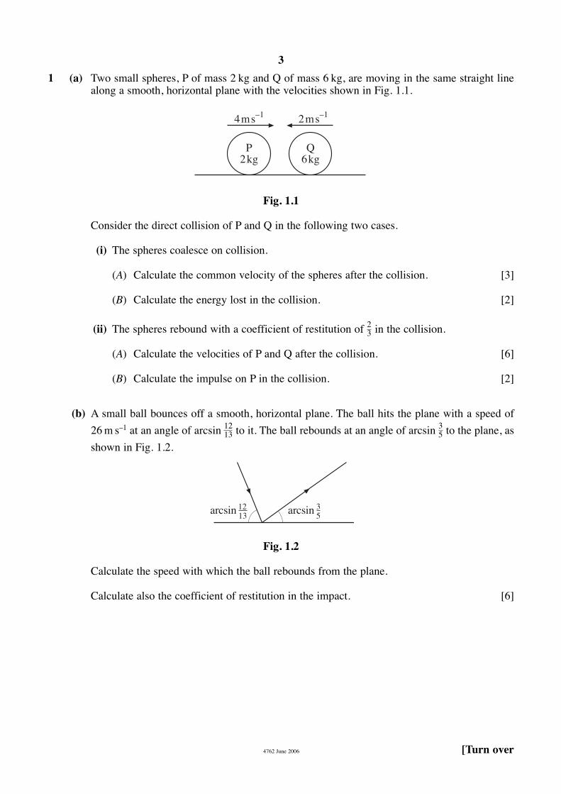
2 Two heavy rods AB and BC are freely jointed together at B and to a wall at A. AB has weight 90 Nand centre of mass at P; BC has weight 75 N and centre of mass at Q. The lengths of the rods andthe positions of P and Q are shown in Fig. 2.1, with the lengths in metres.
Initially, AB and BC are horizontal. There is a support at R, as shown in Fig. 2.1. The system isheld in equilibrium by a vertical force acting at C.
Fig. 2.1
(i) Draw diagrams showing all the forces acting on rod AB and on rod BC.
Calculate the force exerted on AB by the hinge at B and hence the force required at C. [6]
The rods are now set up as shown in Fig. 2.2. AB and BC are each inclined at 60° to the verticaland C rests on a rough horizontal table. Fig. 2.3 shows all the forces acting on AB, including theforces X N and Y N due to the hinge at A and the forces U N and V N in the hinge at B. The rodsare in equilibrium.
(ii) By considering the equilibrium of rod AB, show that [3]
(iii) Draw a diagram showing all the forces acting on rod BC. [1]
(iv) Find a further equation connecting U and V and hence find their values. Find also the frictionalforce at C. [8]
60 3 3= +U V .
A
B
Q
C
P60∞60∞
P
90NXN
YN
V N
UN
60∞B
A
Fig. 2.3Fig. 2.2
A P R
12 2
B
10.5
Q C
90N 75N
4762 June 2006
5
3 (a) A car of mass 900 kg is travelling at a steady speed of up a hill inclined at to the horizontal. The power required to do this is 20 kW.
Calculate the resistance to the motion of the car. [4]
(b) A small box of mass 11 kg is placed on a uniform rough slope inclined at arccos 12––13 to thehorizontal. The coefficient of friction between the box and the slope is m.
(i) Show that if the box stays at rest then [3]
For the remainder of this question, the box moves on a part of the slope where .
The box is projected up the slope from a point P with an initial speed of It travels adistance of 1.5 m along the slope before coming instantaneously to rest. During this motion,the work done against air resistance is 6 joules per metre.
(ii) Calculate the value of v. [5]
As the box slides back down the slope, it passes through its point of projection P and laterreaches its initial speed at a point Q. During this motion, once again the work done against airresistance is 6 joules per metre.
(iii) Calculate the distance PQ. [6]
[Question 4 is printed overleaf.]
v m s–1.
m � 0.2
m � 512 .
arcsin 0.116 m s–1
4762 June 2006
6
4762 June 2006
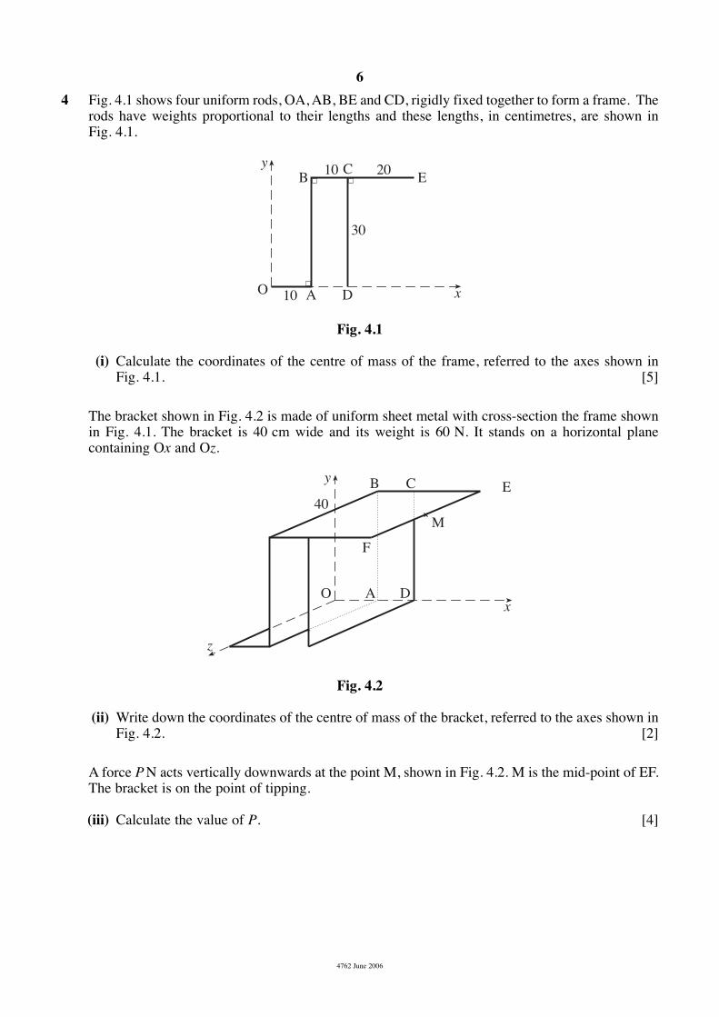
4 Fig. 4.1 shows four uniform rods, OA, AB, BE and CD, rigidly fixed together to form a frame. Therods have weights proportional to their lengths and these lengths, in centimetres, are shown in Fig. 4.1.
Fig. 4.1
(i) Calculate the coordinates of the centre of mass of the frame, referred to the axes shown in Fig. 4.1. [5]
The bracket shown in Fig. 4.2 is made of uniform sheet metal with cross-section the frame shownin Fig. 4.1. The bracket is 40 cm wide and its weight is 60 N. It stands on a horizontal planecontaining Ox and Oz.
Fig. 4.2
(ii) Write down the coordinates of the centre of mass of the bracket, referred to the axes shown inFig. 4.2. [2]
A force P N acts vertically downwards at the point M, shown in Fig. 4.2. M is the mid-point of EF.The bracket is on the point of tipping.
(iii) Calculate the value of P. [4]
40
O
B
F
C
xA D
yE
M
z
10
10 20
30
O
B ECy
xA D
7
4762 June 2006
In another situation, a horizontal force Q N acts through M parallel to EB and in the direction fromE to B. The value of Q is increased from zero with the bracket in equilibrium at all times.
(iv) Draw a diagram showing the forces acting on the bracket when it is on the point of tipping.[1]
(v) If the limiting frictional force between the bracket and the plane is 30 N, does the bracket slideor tip first as Q is increased? [5]
Mark Scheme 4762June 2006
4762 Mark Scheme June 2006
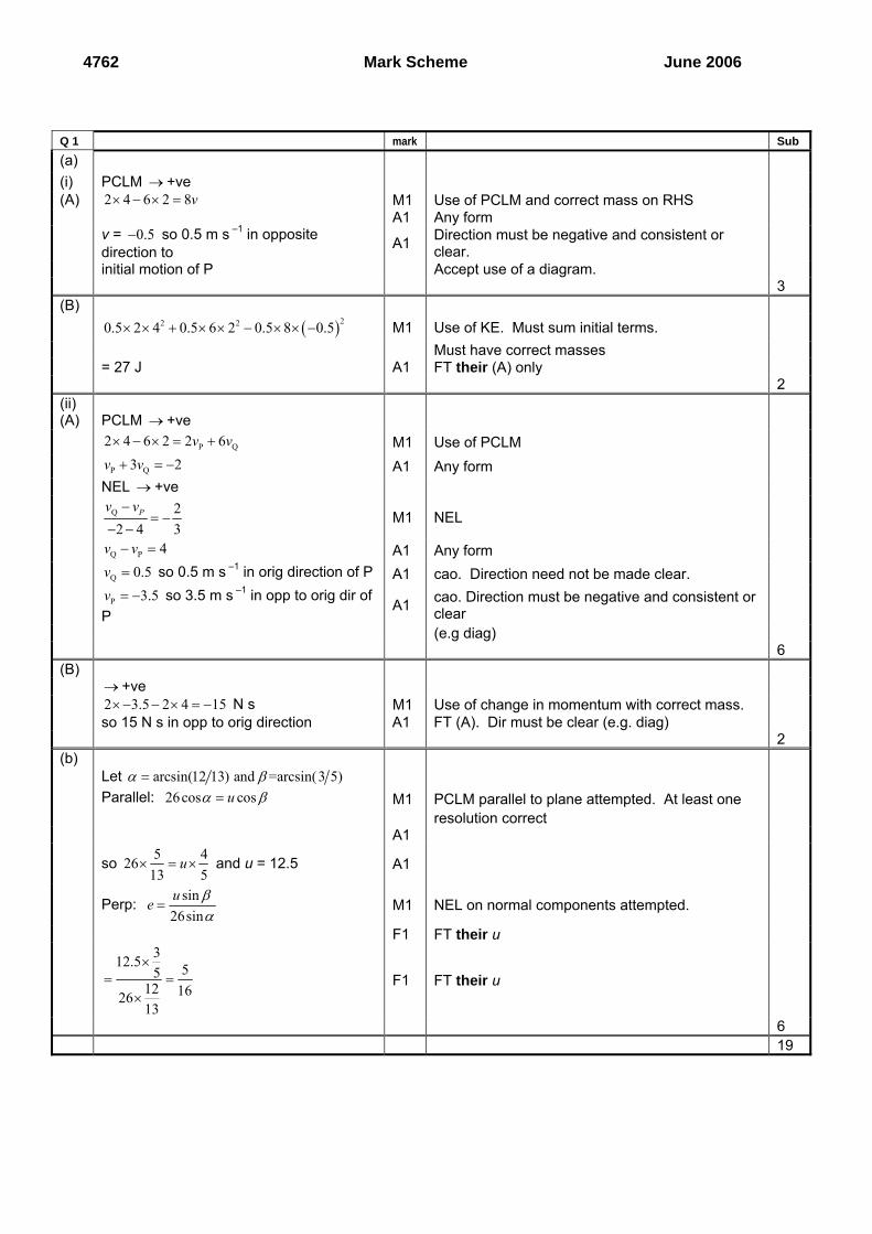
Q 1 mark Sub (a) (i) PCLM → +ve (A) 2 4 6 2 8v× − × = M1 Use of PCLM and correct mass on RHS A1 Any form v = 0.5− so 0.5 m s –1 in opposite
direction to A1 Direction must be negative and consistent or clear.
initial motion of P Accept use of a diagram. 3 (B) ( )22 20.5 2 4 0.5 6 2 0.5 8 0.5× × + × × − × × − M1 Use of KE. Must sum initial terms. Must have correct masses = 27 J A1 FT their (A) only 2 (ii) (A) PCLM → +ve
P Q2 4 6 2 2 6v v× − × = + M1 Use of PCLM P Q3 2v v+ = − A1 Any form NEL → +ve Q 2
2 4 3Pv v−
= −− −
M1 NEL
Q P 4v v− = A1 Any form Q 0.5v = so 0.5 m s –1 in orig direction of P A1 cao. Direction need not be made clear. P 3.5v = − so 3.5 m s –1 in opp to orig dir of
P A1 cao. Direction must be negative and consistent or
clear
(e.g diag) 6 (B) → +ve 2 3.5 2 4 15× − − × = − N s M1 Use of change in momentum with correct mass. so 15 N s in opp to orig direction A1 FT (A). Dir must be clear (e.g. diag) 2 (b) Let arcsin(12 13) and =arcsin(3 5)α β= Parallel: 26cos cosuα β= M1 PCLM parallel to plane attempted. At least one resolution correct A1
so 5 42613 5
u× = × and u = 12.5 A1
Perp: sin
26sinue β
α= M1 NEL on normal components attempted.
F1 FT their u 312.5 55
12 162613
×= =
× F1 FT their u
6 19
4762 Mark Scheme June 2006
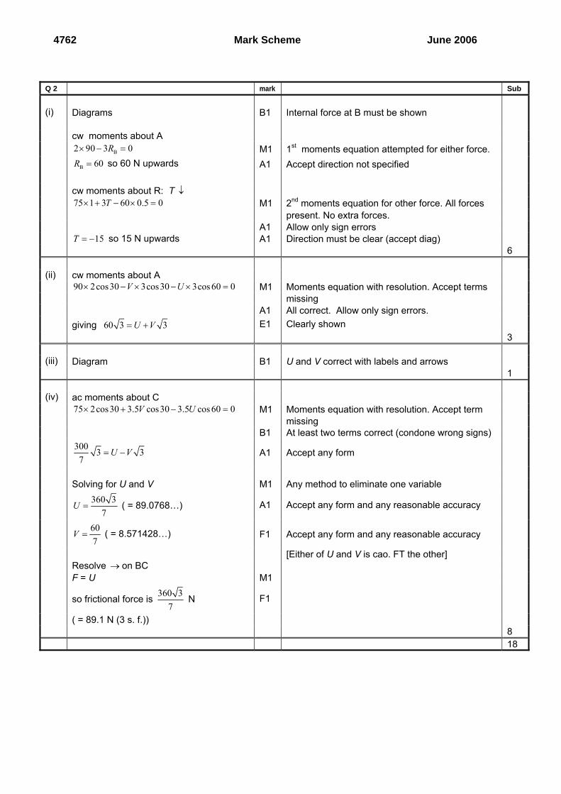
Q 2 mark Sub
(i) Diagrams B1 Internal force at B must be shown cw moments about A B2 90 3 0R× − = M1 1st moments equation attempted for either force. B 60R = so 60 N upwards A1 Accept direction not specified cw moments about R: T ↓ 75 1 3 60 0.5 0T× + − × = M1 2nd moments equation for other force. All forces present. No extra forces. A1 Allow only sign errors 15T = − so 15 N upwards A1 Direction must be clear (accept diag) 6 (ii) cw moments about A 90 2cos30 3cos30 3cos 60 0V U× − × − × = M1 Moments equation with resolution. Accept terms missing A1 All correct. Allow only sign errors. giving 60 3 3U V= + E1 Clearly shown 3 (iii) Diagram B1 U and V correct with labels and arrows 1 (iv) ac moments about C 75 2cos30 3.5 cos30 3.5 cos 60 0V U× + − = M1 Moments equation with resolution. Accept term missing B1 At least two terms correct (condone wrong signs) 300 3 3
7U V= − A1 Accept any form
Solving for U and V M1 Any method to eliminate one variable 360 3
7U = ( = 89.0768…) A1 Accept any form and any reasonable accuracy
607
V = ( = 8.571428…) F1 Accept any form and any reasonable accuracy
[Either of U and V is cao. FT the other] Resolve → on BC F = U M1
so frictional force is 360 37
N F1
( = 89.1 N (3 s. f.)) 8 18
4762 Mark Scheme June 2006
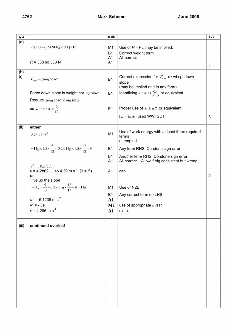
Q 3 mark Sub (a) ( )20000 900 0.1 16R g= + × × M1 Use of P = Fv, may be implied. B1 Correct weight term A1 All correct R = 368 so 368 N A1 4 (b) (i)
max cosF mgμ α= B1 Correct expression for maxF or wt cpt down slope
(may be implied and in any form) Force down slope is weight cpt sinmg α B1 Identifying 5sin as 13α or equivalent Require cos sinmg mgμ α α≥
so 5tan12
μ α≥ = E1 Proper use of F Rμ≤ or equivalent.
[ tanμ α= used WW; SC1] 3 (ii) either 20.5 11 v× × M1 Use of work energy with at least three required
terms
attempted 5 1211 1.5 0.2 11 1.5 9
13 13g g= × × + × × × + B1 Any term RHS. Condone sign error.
B1 Another term RHS. Condone sign error. A1 All correct . Allow if trig consistent but wrong 2 18.3717...v = v = 4.2862… so 4.29 m s –1 (3 s. f.) A1 cao or 5 + ve up the slope 5 1211 0.2 11 6 11
13 13g g a− × − × × − = M1 Use of N2L
B1 Any correct term on LHS a = - 6.1239 m s-2 A1 v2 = - 3a M1 use of appropriate uvast v = 4.286 m s-1 A1 c.a.o. (iii) continued overleaf
4762 Mark Scheme June 2006
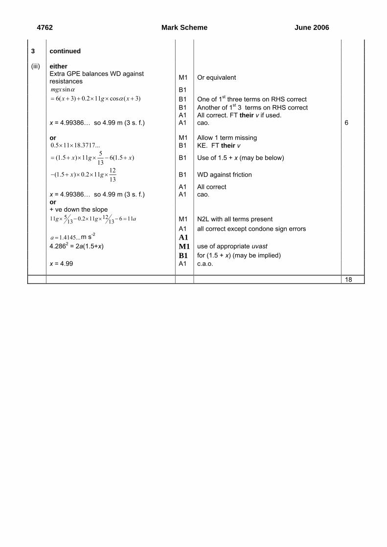
3 continued (iii) either Extra GPE balances WD against
resistances M1 Or equivalent
sinmgx α B1 6( 3) 0.2 11 cos ( 3)x g xα= + + × × + B1 One of 1st three terms on RHS correct B1 Another of 1st 3 terms on RHS correct A1 All correct. FT their v if used. x = 4.99386… so 4.99 m (3 s. f.) A1 cao. 6 or M1 Allow 1 term missing 0.5 11 18.3717...× × B1 KE. FT their v 5(1.5 ) 11 6(1.5 )
13x g x= + × × − + B1 Use of 1.5 + x (may be below)
12(1.5 ) 0.2 1113
x g− + × × × B1 WD against friction
A1 All correct x = 4.99386… so 4.99 m (3 s. f.) A1 cao. or + ve down the slope 5 1211 0.2 11 6 1113 13g g a× − × × − = M1 N2L with all terms present A1 all correct except condone sign errors 1.4145...a = m s-2 A1 4.2862 = 2a(1.5+x) M1 use of appropriate uvast B1 for (1.5 + x) (may be implied) x = 4.99 A1 c.a.o. 18
4762 Mark Scheme June 2006
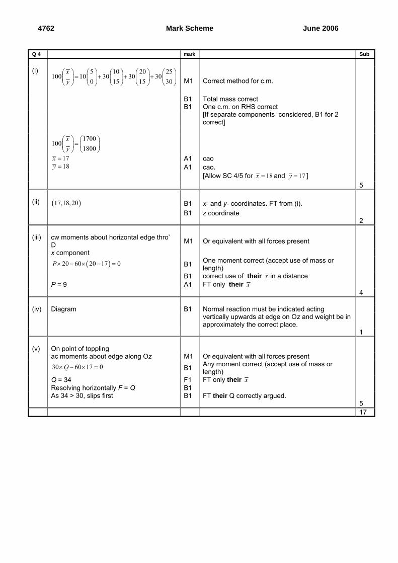
Q 4 mark Sub (i) 5 10 20 25
100 10 30 30 300 15 15 30
xy
⎛ ⎞ ⎛ ⎞ ⎛ ⎞ ⎛ ⎞ ⎛ ⎞= + + +⎜ ⎟ ⎜ ⎟ ⎜ ⎟ ⎜ ⎟ ⎜ ⎟
⎝ ⎠ ⎝ ⎠ ⎝ ⎠ ⎝ ⎠ ⎝ ⎠
M1 Correct method for c.m.
B1 Total mass correct B1 One c.m. on RHS correct [If separate components considered, B1 for 2
correct]
1700
1001800
xy
⎛ ⎞ ⎛ ⎞=⎜ ⎟ ⎜ ⎟
⎝ ⎠ ⎝ ⎠
17x = A1 cao 18y = A1 cao. [Allow SC 4/5 for 18x = and 17y = ] 5 (ii) ( )17,18, 20 B1 x- and y- coordinates. FT from (i). B1 z coordinate 2 (iii) cw moments about horizontal edge thro’
D M1 Or equivalent with all forces present
x component ( )20 60 20 17 0P × − × − = B1 One moment correct (accept use of mass or
length)
B1 correct use of their x in a distance P = 9 A1 FT only their x 4 (iv) Diagram B1 Normal reaction must be indicated acting vertically upwards at edge on Oz and weight be in approximately the correct place. 1 (v) On point of toppling ac moments about edge along Oz M1 Or equivalent with all forces present 30 60 17 0Q× − × = B1 Any moment correct (accept use of mass or
length)
Q = 34 F1 FT only their x Resolving horizontally F = Q B1 As 34 > 30, slips first B1 FT their Q correctly argued. 5 17
Report on the Units taken in June 2006
4762 - Mechanics 2 General Comments Many candidates could make some progress with at least some part of every question and gain some credit for their work. There were many candidates who had more difficulty with questions 2 and/or 3 than with questions 1 or 4. The standard of presentation of most scripts was pleasing but, as has happened in other sessions, in some cases diagrams were too poor to be useful. Many candidates do not appreciate the value of a diagram in finding a solution or in conveying to an examiner information relevant to the answer. Labelling of forces should be clear and unambiguous and the diagram large enough for the information to be clearly shown. Candidates who state in a solution which process or principle is being employed tend to be more successful than those who omit this information – stating the principle being employed seems to help the candidate to use it properly. The standard of algebraic manipulation was, for some candidates, so low as to make it hard for the candidate to demonstrate knowledge of mechanics; this was seen particularly in the attempts to solve simultaneous equations or to rearrange formulae. Efforts were not helped by the use of some clumsy notation with regard to trigonometric functions. e.g. it was common to see expressions such as cos( 12arcsin 13 ) with no attempt being made to simplify this.
Comments on Individual Questions 1 Impulse and Momentum Many candidates gained good marks on this question. The main cause of error was in
failure to indicate clearly the direction of the vector answer. (a) (i) (A) This part posed few problems for the majority of candidates.
(B) Many completely correct solutions were seen to this part. Errors were mainly arithmetic.
(ii) (A) It was pleasing to see many completely correct solutions to this part. Candidates who did not draw a fully labelled diagram were less successful than those who did. Without a diagram, the sign convention was not always as clear as it had to be and errors occurred, usually in the application of Newton’s experimental law.
(B) Only the most able (identified by their success on the paper overall) gained full credit for this part. Many candidates failed to indicate direction and a few thought that impulse was equal to change in kinetic energy.
(b) A large number of candidates did well on this part of the question. Most appreciated that there would be no change in speed parallel to the plane and could hence calculate the speed of the rebound. Almost as many could find the coefficient of restitution either by analysing the motion perpendicular to the plane and applying Newton’s experimental law or by using tanβ = e tanα.
2 Moments and Resolving Unfortunately many candidates did not apply Newton’s third law properly, hence they
could not gain the credit for the diagrams required in part (i) and part (iii). However, the majority of candidates understood that moments were required along with some resolution of forces and could gain at least some credit in the other parts of the question.
(i) Many candidates could correctly calculate the force exerted on AB by the hinge at B and could go on to use this to attempt to evaluate the force at C. Of those candidates who failed to obtain the correct answer those who tackled the problem by looking at rods AB and BC separately tended to gain more credit than those who treated AC initially as a single rigid rod.
(ii) The majority of candidates encountered little difficulty with this part.
29
Report on the Units taken in June 2006
(iii) Many candidates applied Newton’s third law correctly in the horizontal direction giving
U in the opposite direction to the diagram for rod AB but failed to do so in the vertical direction and drew a diagram in which V acted vertically upwards as in the diagram for rod AB.
(iv) A large number of candidates made a good attempt at setting up a second equation in U and V and then went on to try to find a solution to the simultaneous equations. The majority of these then correctly deduced the size of the frictional force.
3 Work and Energy It was very satisfying to see that the majority of candidates tried to use work-energy
methods throughout this question and did so with some success. Correct solutions were not obtained in some cases because of the absence of a diagram or the omission of an indication about the sign convention adopted.
(a) Almost all of the candidates appreciated the need to use P = Fv and very many of them obtained full credit for that part.
(b) (i) The amount of explanation required to establish the given result was not appreciated by the majority of candidates. It was common to see 5 hence 12 12μ μ= 5≥ without any
supporting reasoning. Persistent use of the notation 12sin(arccos )13 without showing or
stating that this was 513 meant that many candidates presented an incomplete argument
in support of their answers. Very few candidates mentioned the maximum value of the frictional force either implicitly or explicitly and some used rounded decimal fractions throughout and then claimed this was 5
12 .
(ii) Many good attempts were seen to this part of the question. Errors usually involved one of the terms in the work-energy equation. Those candidates who used Newton’s second law and the constant acceleration formulae were not usually as successful as those using the work- energy principle.
(iii) Again, some attempts worthy of significant credit were seen for this part, with errors of a similar type to those in part (ii). Candidates who made their method clear usually gained more credit than those who attempted to write down single terms independently and then use these in an equation. Sign errors were common.
4 Centres of Mass This question was attempted well by almost all candidates with a large number of
candidates gaining significant credit. Some excellent solutions were seen. (i) Most candidates had little or no difficulty with this part. (ii) Few encountered problems with this part. (iii) The majority of candidates could obtain some credit for this part with errors being
mainly arithmetic. A few candidates attempted to take moments about the edge through O rather than the edge through D but forgot to include the term containing the reaction at the edge through D.
(iv) Many of the diagrams offered here were poor with forces either omitted or unlabelled. A large number of candidates did not appreciate that the reaction would act vertically upwards at some point on the edge through Oz but showed it acting along the edge through A. Others omitted it altogether.
(v) Errors in this part tended to be only arithmetic and it was pleasing to see that many candidates could produce a coherent argument to support their conclusion.
30


![OXFORD CAMBRIDGE AND RSA EXAMINATIONS | ililI ill] llill ...](https://static.fdocuments.in/doc/165x107/627195b46bffa50d6f572f23/oxford-cambridge-and-rsa-examinations-ilili-ill-llill-.jpg)