Owners’s Manual MG2000 Tachometer - Faria Beede · Page 1 Volvo MG2000™ Tachometer Manual FARIA...
22
MG2000 ™ Tachometer IS0208 rev. A ecr#5028 11/17/04 Owners’s Manual
Transcript of Owners’s Manual MG2000 Tachometer - Faria Beede · Page 1 Volvo MG2000™ Tachometer Manual FARIA...

MG2000™ Tachometer
IS0208 rev. A ecr#5028 11/17/04
Owners’s Manual
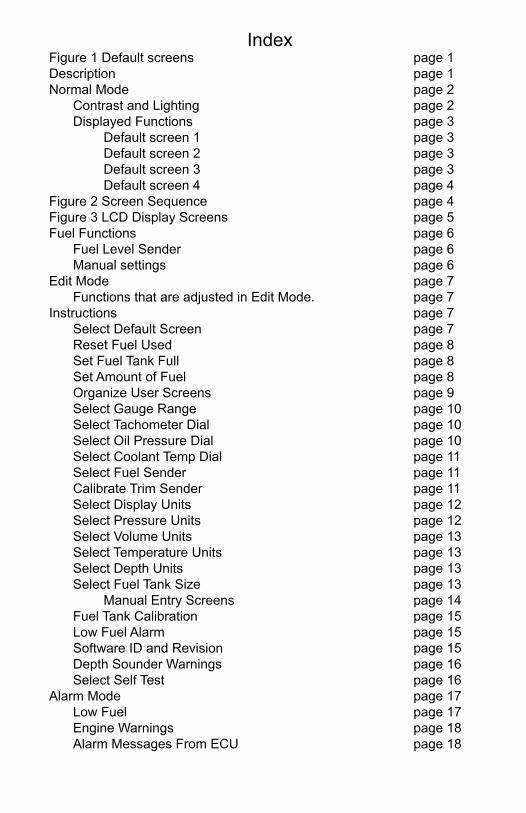
IndexFigure 1 Default screens page 1Description page 1Normal Mode page 2 Contrast and Lighting page 2 Displayed Functions page 3 Default screen 1 page 3 Default screen 2 page 3 Default screen 3 page 3 Default screen 4 page 4Figure 2 Screen Sequence page 4Figure 3 LCD Display Screens page 5Fuel Functions page 6 Fuel Level Sender page 6 Manual settings page 6Edit Mode page 7 Functions that are adjusted in Edit Mode. page 7Instructions page 7 Select Default Screen page 7 Reset Fuel Used page 8 Set Fuel Tank Full page 8 Set Amount of Fuel page 8 Organize User Screens page 9 Select Gauge Range page 10 Select Tachometer Dial page 10 Select Oil Pressure Dial page 10 Select Coolant Temp Dial page 11 Select Fuel Sender page 11 Calibrate Trim Sender page 11 Select Display Units page 12 Select Pressure Units page 12 Select Volume Units page 13 Select Temperature Units page 13 Select Depth Units page 13 Select Fuel Tank Size page 13 Manual Entry Screens page 14 Fuel Tank Calibration page 15 Low Fuel Alarm page 15 Software ID and Revision page 15 Depth Sounder Warnings page 16 Select Self Test page 16 Alarm Mode page 17 Low Fuel page 17 Engine Warnings page 18 Alarm Messages From ECU page 18

Page 1
Volvo MG2000™ Tachometer ManualFARIA MG2000™ tachometer combines the features of an ECU serial bus gateway and several instruments into one unit:• The tachometer is analog in appear-
ance but is but driven by a stepper motor for digital accuracy.
• The high resolution LCD screen dis-plays information for many other func-tions and the various “screens” can be configured as the user wishes. As received, the screens are configured as shown in Figure 1.
Figure 1
DecriptionThe MG2000™ tachometer receives digital engine data from the Engine Control Unit (ECU) via the Volvo SAE J1708/J1587 bus and can receive GPS information via a NMEA 0183 connection to a suitable GPS unit. GPS information is displayed in the MG2000™ speedometer. Analog inputs are provided for two non-engine sensors; fuel level and trim position. A direct pressure port allows monitoring of engine water pressure.
The MG2000™ provides a Faria Bus output to allow use of various 5, 4, and 2 inch instruments with the MG2000™.
The Faria MG2000™ tachometer will turn on when the ignition key is turned on and will turn off when the ignition key is turned off. The unit will power up showing the last screen selected by the user prior to shut off. The default screens are shown in Figure 1.
The instrument has three push buttons; “M” (Mode), “DOWN”, and “UP”; that control the functions available. The “M” (Mode) button is used to change the function of the LCD display and to access submenus and adjustable settings. The “DOWN” and “UP” buttons are used to modify the settings.
In “NORMAL” operation mode, pressing the “Mode” button and then pressing “DOWN” or “UP” causes the display to cycle between the available screens (see Figure 2).

Page 2
Press the “Mode” button to exit the “screen selection mode” and return to normal mode or do not push any buttons for 4 seconds and the current screen will stay selected and the unit will return to normal mode (see Figure 3).
In “NORMAL” operation mode, press the “Mode” and “UP” buttons to change to the “EDIT” menus (see Figure 3 and EDIT mode below).
When the “Edit” menus have been selected, press the “Mode” button to return to normal mode.
Press the “DOWN” or “UP” buttons to cycle between the available “Edit” functions.
Press and hold the “DOWN” and “UP” buttons for two (2) seconds to select an “Edit” function to change. Within each “editing” function the “DOWN” or “UP” buttons select settings or sub-functions.
Follow the instructions in the “Edit” mode section of this manual to save the new settings after you select / adjust them.
Normal ModeWhen the MG2000™ is turned on, the unit enters “Self Test” mode. The screen will display “The Self Test Mode Is In Operation” for 10 sec. The horn will sound once, the warning lights and back lights will flash.
When this is complete, the software Id and revision screen will show for two seconds, then the user selected “Default” screen will appear. The information below applies to the MG2000™ as received with no user changes to the screen selections. When the unit is turned on, the lighting defaults to off.
Contrast and LightingIn the “NORMAL” operating mode the instrument LCD contrast can be adjusted by pressing either the “UP” or “DOWN” buttons.
This adjustment is helpful as lighting conditions and viewing angles change.
To adjust the lighting level intensity of all instruments in the system, both the “UP” and “DOWN” buttons must be held for three seconds.
The lighting intensity of all instruments can now be adjusted by pressing the “DOWN” or “UP” buttons.
Return to “NORMAL” mode by pressing and holding both the “UP” and “DOWN”
Page 3
buttons.
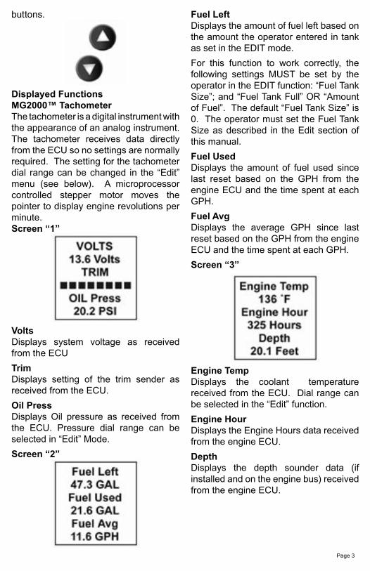
Displayed Functions MG2000™ TachometerThe tachometer is a digital instrument with the appearance of an analog instrument. The tachometer receives data directly from the ECU so no settings are normally required. The setting for the tachometer dial range can be changed in the “Edit” menu (see below). A microprocessor controlled stepper motor moves the pointer to display engine revolutions per minute.Screen “1”
VoltsDisplays system voltage as received from the ECU
TrimDisplays setting of the trim sender as received from the ECU.
Oil PressDisplays Oil pressure as received from the ECU. Pressure dial range can be selected in “Edit” Mode.
Screen “2”
Fuel LeftDisplays the amount of fuel left based on the amount the operator entered in tank as set in the EDIT mode.
For this function to work correctly, the following settings MUST be set by the operator in the EDIT function: “Fuel Tank Size”; and “Fuel Tank Full” OR “Amount of Fuel”. The default “Fuel Tank Size” is 0. The operator must set the Fuel Tank Size as described in the Edit section of this manual.
Fuel UsedDisplays the amount of fuel used since last reset based on the GPH from the engine ECU and the time spent at each GPH.
Fuel AvgDisplays the average GPH since last reset based on the GPH from the engine ECU and the time spent at each GPH.
Screen “3”
Engine TempDisplays the coolant temperature received from the ECU. Dial range can be selected in the “Edit” function.
Engine HourDisplays the Engine Hours data received from the engine ECU.
DepthDisplays the depth sounder data (if installed and on the engine bus) received from the engine ECU.

Page 4
Screen “4”
This screen displays fault conditions based on engine data received from the ECU or alarms based on internally set alarm points. Engine alarms from the ECU will be displayed as “Check Engine !” or “Engine Emergency Stop !”. Accessing the “View“ mode when the Alarm screen appears will allow more information to be displayed about the alarm, if provided by the engine.
Internal alarm values can be set for “Low Fuel” and other functions. Alarms for these settings will appear as required.
LCD Display Screens:In the “NORMAL” mode, press “Mode” once to enter screen “Select” mode,
press “UP” or “Down” to move between screens.
Press “Mode” once to return to “NORMAL” mode.
Screen “1”
Screen “2”
Screen “3”
Screen “4”Alarms
Figure 2

Page 5

Page 6
Fuel FunctionsFuel Level SenderThe FUEL LEVEL SENDER provides the information displayed in the Fuel Level bar graph. This display is the equivalent of a standard fuel gauge and should be used as the reference for the fuel remaining.
Each filled block represents 1/8 of a tank and when the fuel tank is empty only empty blocks will be displayed. For best accuracy, the fuel level sender should be calibrated as described in Edit Mode section of this manual.
Manual settingsThe “Fuel Left” and “Range” display values are dependant on accurately setting the values for “Fuel Tank Size” and either “Fuel Tank Full” or “Amount of Fuel” in the MG2000™ Tachometer.
“Fuel Left” is calculated based on the amount of fuel entered in these settings (the amount of fuel the operator indicates is in the fuel tank) and the fuel flow of the engine. “Range” is calculated based on “Fuel Left”, fuel flow, and current speed
Fuel Level Sender
Speedometer
�����������������������������������������
������������
�������������
�������������
��
���� ������

Page 7
Edit ModeThe “Edit” mode is used to adjust or set the values of numerous functions and options in the MG2000. The procedure below specifies the steps to be taken in the “Edit” mode to adjust / set each option.
To enter “EDIT” mode, press the “Mode” and “UP” buttons while in “NORMAL” modeTo return to “NORMAL” mode, press “Mode” button once while in “EDIT” mode
Instructions – Function LINE DISPLAY
Select Default Screen
1 Select
2 Default
3 Screen
Press & Hold “UP” & “DOWN” for 2 sec to select the “default screen”
Press “UP” or “DOWN” to select another function or “Mode” to return to “Normal” mode
(Display Screen 1 is the “default” at first turn on)
1DisplayScreen
12
3
Press & Hold “UP” & “DOWN” for 2 sec to select screen 1 as the “default screen” and exit
1Display
NextScreen
Press “UP” or “DOWN” to select another screen 2
3
Press & Hold “UP” & “DOWN” for 2 sec to select this screen as the “default screen” and exit
Press “UP” or “DOWN” to select another screenRepeat until desired “default screen” is selected
Press “UP” or “DOWN” to select another function or “Mode” to return to “Normal” mode
Functions that are set or adjusted in the “Edit” mode
1. Select Default Screen.2. Reset Fuel Used.3. Set Fuel Tank Full.4. Set Amount Of Fuel.5. Organize User Screens.6. Select Gauge Range.7. Select Fuel Sender.8. Calibrate Trim Sender.9. Select Display Units.10. Select Fuel Tank Size.11. Fuel Tank Calibrate.12. Low Fuel Alarm.13. Software Id and Revision.14. Depth Sounder Warnings.15. Select Self Test.

Page 8
Reset Fuel Used
1 Reset
2 Fuel
3 Used
Press & Hold “UP” & “DOWN” for 2 sec to reset “fuel used” to zero (0) Automatically resets fuel used to zero and returns to “Edit mode”
Press “UP” or “DOWN” to select another function or “Mode” to return to “Normal” mode
Set Fuel Tank Full
1 Set
2 Fuel Tank
3 Full
NOTE: In order to use the “Fuel Left” function, the owner must set this function when the fuel tank is filled or use the set current amount of fuel below. In addition, if “set fuel tank full” function is used, the “fuel tank size” must be set correctly to the size of the fuel tank in this application. The computer will monitor fuel usage and calculate the fuel left in the tank. This function does not replace the fuel level function provided by the fuel sender and should be used with caution.
Press & Hold “UP” & “DOWN” for 2 sec to set “fuel tank full”Automatically sets the fuel available to the tank size selected by the user and returns to “Edit mode”
Press “UP” or “DOWN” to select another function or “Mode” to return to “Normal” mode
Set Amount of Fuel
1 Set
2 Amount
3 Of Fuel
NOTE: If a known amount of fuel is in the fuel tank but it is not full, this function can be used to indicate the amount of fuel available. The “fuel left” function will then use the amount of fuel entered to calculate the “fuel left”
Press & Hold “UP” & “DOWN” for 2 sec to select “current amount of fuel”
Press “UP” or “DOWN” to select another function or “Mode” to return to “NORMAL” mode
Page 9
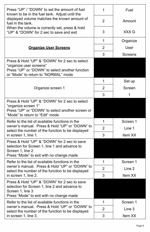
Press “UP” / “DOWN” to set the amount of fuel known to be in the fuel tank. Adjust until the displayed volume matches the known amount of fuel in the tank.When the volume is correctly set, press & hold “UP” & “DOWN” for 2 sec to save and exit
1 Fuel
2 Amount
3 XXX G
Organize User Screens
1 Organize
2 User
3 Screens
Press & Hold “UP” & “DOWN” for 2 sec to select “organize user screens”Press “UP” or “DOWN” to select another function or “Mode” to return to “NORMAL” mode
Organize screen 1
1 Set up
2 Screen
3 1
Press & Hold “UP” & “DOWN” for 2 sec to select “organize screen 1”Press “UP” or “DOWN” to select another screen or “Mode” to return to “Edit” mode
Refer to the list of available functions in the owner’s manual. Press & Hold “UP” or “DOWN” to select the number of the function to be displayed in screen 1, line 1.
1 Screen 1
2 Line 1
3 Item XX
Press & Hold “UP” & “DOWN” for 2 sec to save selection for Screen 1, line 1 and advance to Screen 1, line 2Press “Mode” to exit with no change made
Refer to the list of available functions in the owner’s manual. Press & Hold “UP” or “DOWN” to select the number of the function to be displayed in screen 1, line 2.
1 Screen 1
2 Line 2
3 Item XX
Press & Hold “UP” & “DOWN” for 2 sec to save selection for Screen 1, line 2 and advance to Screen 1, line 3Press “Mode” to exit with no change made
Refer to the list of available functions in the owner’s manual. Press & Hold “UP” or “DOWN” to select the number of the function to be displayed in screen 1, line 3.
1 Screen 1
2 Line 3
3 Item XX

Page 10
Press & Hold “UP” & “DOWN” for 2 sec to save selection for Screen 1, line 3 and advance to view new screen 1.Press “Mode” to exit with no change made
Press & Hold “UP” & “DOWN” for 2 sec to save new Screen 1 an exit to Press “Mode” to exit with no change made
1Display
Customer’sNew screen 1
2
3
Repeat for remaining screens (2, 3)
Press “UP” or “DOWN” to select another function or “Mode” to return to “NORMAL” mode
Select Gauge Range
1 Select
2 Gauge
3 Range
Press & Hold “UP” & “DOWN” for 2 sec to select “gauge range”Press “UP” or “DOWN” to select another function
Select Tachometer Dial
1 Select
2 Tachometer
3 Dial
Press & Hold “UP” & “DOWN” for 2 sec to select “tachometer dial”Press “UP” or “DOWN” to select another “gauge range”
Press “UP” / “DOWN” to select.When selected, press & hold “UP” & “DOWN” for 2 sec to save and return to “gauge range” selection
1 > 4000 RPM
2 6000 RPM
3 7000 RPM
Select Oil Pressure Dial
1 Select
2 Oil Pressure
3 Dial
Press & Hold “UP” & “DOWN” for 2 sec to select “oil pressure dial”Press “UP” or “DOWN” to select another “gauge range”

Page 11
Press “UP” / “DOWN” to select.When selected, press & hold “UP” & “DOWN” for 2 sec to save and return to “gauge range” selection
1 > 60 psi
2 80 psi
3 100 psi
Select Coolant Temp Dial
1 Select
2 Coolant Temp
3 Dial
Press & Hold “UP” & “DOWN” for 2 sec to select “coolant temp dial”Press “UP” or “DOWN” to select another “gauge range”
Press “UP” / “DOWN” to select.When selected, press & hold “UP” & “DOWN” for 2 sec to save and return to “gauge range” selection
1 > 60 –220 F
2 100 – 250 F
3
Select Fuel Sender
1 Select
2 Fuel
3 Sender
Press & Hold “UP” & “DOWN” for 2 sec to select “fuel sender”Press “UP” or “DOWN” to select another function
Press “UP” / “DOWN” to select.When selected, press & hold “UP” & “DOWN” for 2 sec to save and return to select “fuel sender”
1 > USA 240 - 33
2 EU 10 - 180
3
Calibrate Trim Sender
1 Calibrate
2 Trim
3 Sender
Press & Hold “UP” & “DOWN” for 2 sec to select “calibrate trim sender”Press “UP” or “DOWN” to select another function
Using the Trim control, set the trim to the full “UP” position
1 Set Trim
2 UP
3 Press UP
Press “UP” button to save “UP” setting 4 TRIM
5

Page 12
Using the Trim control, set the trim to the full “DOWN” positionPress “DOWN” button to save “DOWN” setting
1 Set Trim
2 DOWN
3 Press DOWN
4 TRIM
5
Press “UP” to recal “UP” if desiredRepeat as necessaryWhen complete, press & hold “UP” & “DOWN” for 2 sec to save and return to “Calibrate Trim Sender”
Select Display Units
1 Select
2 Display
3 Units
Press & Hold “UP” & “DOWN” for 2 sec to select “units”Press “UP” or “DOWN” to select another function
Select Pressure Units
1 Select
2 Pressure
3
Press & Hold “UP” & “DOWN” for 2 sec to select “pressure units”Press “UP” or “DOWN” to select another choice of “units”
Press “UP” / “DOWN” to select.When selected, press & hold “UP” & “DOWN” for 2 sec to save and return to select “units”
1 > PSI
2 BAR
3
Select Volume Units
1 Select
2 Volume
3 Units
Press & Hold “UP” & “DOWN” for 2 sec to select “volume units”Press “UP” or “DOWN” to select another choice of “units

Page 13
Press “UP” / “DOWN” to select.When selected, press & hold “UP” & “DOWN” for 2 sec to save and return to select “units”
1 > GAL
2 LITERS
3
Select Temperature Units
1 Select
2 Temperature
3 Units
Press & Hold “UP” & “DOWN” for 2 sec to select “temperature units”Press “UP” or “DOWN” to select another choice of “units
Press “UP” / “DOWN” to select.When selected, press & hold “UP” & “DOWN” for 2 sec to save and return to select “units”
1 > °F
2 °C
3
Select Depth Units
1 Select
2 Depth
3 Units
Press & Hold “UP” & “DOWN” for 2 sec to select “depth units”Press “UP” or “DOWN” to select another choice of “units
Press “UP” / “DOWN” to select.When selected, press & hold “UP” & “DOWN” for 2 sec to save and return to select “units”
1 > Feet
2 Meters
3 Fathoms
Press “UP” or “DOWN” to select another function or “Mode” to return to “NORMAL” mode
Select Fuel Tank Size
1 Select
2 Fuel Tank
3 Size
Press & Hold “UP” & “DOWN” for 2 sec to select “fuel tank size”Press “UP” or “DOWN” to select another function
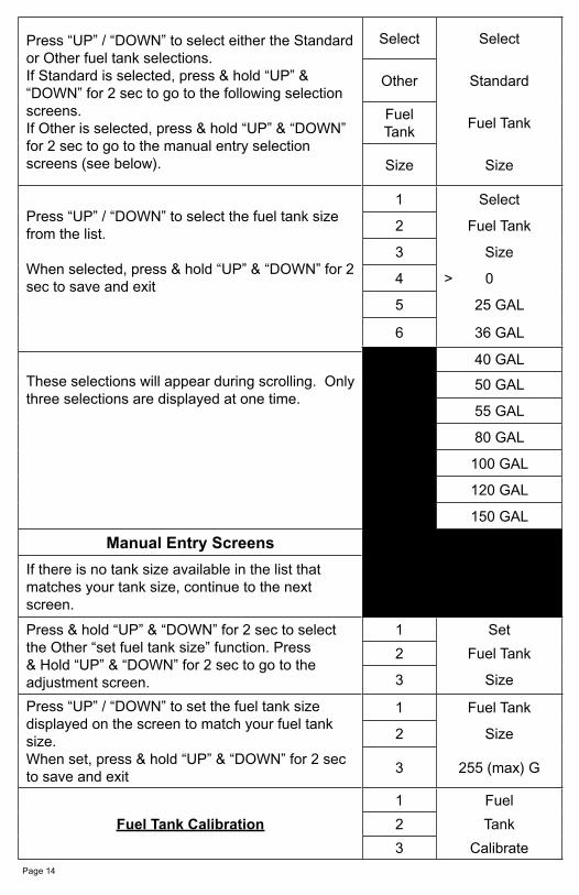
Press “UP” / “DOWN” to select either the Standard or Other fuel tank selections. If Standard is selected, press & hold “UP” & “DOWN” for 2 sec to go to the following selection screens.If Other is selected, press & hold “UP” & “DOWN” for 2 sec to go to the manual entry selection screens (see below).
Select Select
Other Standard
Fuel Tank
Fuel Tank
Size Size
Press “UP” / “DOWN” to select the fuel tank size from the list.
When selected, press & hold “UP” & “DOWN” for 2 sec to save and exit
1 Select
2 Fuel Tank
3 Size
4 > 0
5 25 GAL
6 36 GAL
40 GAL
These selections will appear during scrolling. Only three selections are displayed at one time.
50 GAL
55 GAL
80 GAL
100 GAL
120 GAL
150 GAL
Manual Entry Screens
If there is no tank size available in the list that matches your tank size, continue to the next screen.
Press & hold “UP” & “DOWN” for 2 sec to select the Other “set fuel tank size” function. Press & Hold “UP” & “DOWN” for 2 sec to go to the adjustment screen.
1 Set
2 Fuel Tank
3 Size
Press “UP” / “DOWN” to set the fuel tank size displayed on the screen to match your fuel tank size.When set, press & hold “UP” & “DOWN” for 2 sec to save and exit
1 Fuel Tank
2 Size
3 255 (max) G
Fuel Tank Calibration
1 Fuel
2 Tank
3 Calibrate
Page 14

Press & Hold “UP” & “DOWN” for 2 sec to select “fuel tank calibration”Press “UP” or “DOWN” to select another function
Ensure that fuel tank is as empty as possible1 Calibrate
2 Fuel
3 EMPTY
Press & Hold “UP” & “DOWN” for 2 sec to set empty calibration. Press & Hold “UP” & “DOWN” for 2 sec to save data and return to “Fuel Tank Calibration”.
Press & Hold “UP” & “DOWN” for 2 sec to set Half calibration. Press & Hold “UP” & “DOWN” for 2 sec to save data and return to “Fuel Tank Calibration”.
1 Calibrate
2 Fuel
3 HALF FULL
Press & Hold “UP” & “DOWN” for 2 sec to set Full calibration. Press & Hold “UP” & “DOWN” for 2 sec to save data and return to “Fuel Tank Calibration”.
1 Calibrate
2 Fuel
3 Full
Press “UP” or “DOWN” to select another function or “Mode” to return to “NORMAL” mode
Low Fuel Alarm
1 Low
2 Fuel
3 Alarm
Press & Hold “UP” & “DOWN” for 2 sec to select “low fuel alarm”Press “UP” or “DOWN” to select another function
Adjust low fuel alarm settingPress “UP” or “DOWN” to set desired “low fuel alarm” setting. Line 3 value will adjust.Press & Hold “UP” & “DOWN” for 2 sec to save “low fuel alarm” and exit
1 Low
2 Fuel
3 XX.X G
Press “UP” or “DOWN” to select another function or “Mode” to return to “NORMAL” mode
Software Id
&
Software Id and Revision Revision
Minigateway
PGFXXXX-X
Page 15

Depth Sounder Warnings
1 Shallow warning
2 Deep warning
3 Keel Offset
Press & Hold “UP” & “DOWN” for 2 sec to select “warning or offset”. Press “UP” or “DOWN” to adjust the functionPress & Hold “UP” & “DOWN” for 2 sec to select “warning or offset”. Press “UP” or “DOWN” to adjust the functionPress & Hold “UP” & “DOWN” for 2 sec to return to setting warnings or offset.Press “UP” or “DOWN” to select another “warning” or “offset”.
Press the “MODE” button to return to the “EDIT” mode. Press “MODE” button to return to normal mode.
Select Self Test
1 Select
2 Self
3 Test
Press & Hold “UP” & “DOWN” for 2 sec to select “self test”Press “UP” or “DOWN” to select another function
This screen will display for 10 sec.The horn will sound once.The warning lights will flash three timesThe backlights will flash three times
1 The
1a Self
2 Test
2a Mode
3 Is in
3a Operation
When “self test” is complete the unit will return to the “Edit mode”Press “UP” or “DOWN” to select another function or “Mode” to return to “NORMAL” mode
Page 16

Available Functions for Display in J1708 / J1587 MG2000 Tachometer Screens
The functions listed below can be displayed in the user configurable screens. All of the functions may not be available in your installation. If a function is selected for display and that function does not appear on the screen, the function does not exist in this installation. A function is selected for display by selecting it’s number from the list below.
1. Volts 2. Trim3. Oil pressure4. Engine Temp5. Engine Hour6. Fuel Left7. Fuel Used8. Fuel avg9. Depth Alarm Mode
The “alarm” screen appears only if an alarm condition exists. The alarm condition may be a warning sent from the engine ECU or a “local” alarm such as “Low Fuel”. When an alarm condition occurs, the “Alarm Screen” will appear and the screens described below will be displayed.
The descriptions below also explain how to temporarily override the alarm screen and audible / visual warnings and return to “NORMAL” mode. In all cases, the alarm will re-occur after a period of time to ensure that the user remembers the alarm condition. Once an alarm condition has been corrected, the alarm screen, horn, and warning lights will no longer be displayed. An “ALARMS CLEAR !” screen will be displayed until the MODE then either UP or DOWN buttons are pressed.
ALARM MODE LINE DISPLAY
The “Alarm” screen will only appear if a local alarm or an engine alarm occurs.Local alarm is “low fuel”.”Only two engine alarms appear automatically, “Check Engine” and“Engine Emergency Stop”. Follow the instructions provided to view more information about engine alarms.
LOW FUEL
Displays “low fuel” warningRed LED blinksHorn “beeps”
1 Low
2 Fuel
3 !
Page 17

Press “Mode” to turn off LED, silence alarm horn, and return to “Run” mode. Alarm will reactivate in 15 minutes but can continue to be deactivated as required.
ENGINE WARNINGS
Any engine alarm except “Engine Emergency Stop”Red LED blinksHorn “beeps”
1 CHECK
2 ENGINE
3 !
“Engine Emergency Stop” alarmRed LED on continuouslyHorn on continuously
1 ENGINE
2 EMERGENCY
3 STOP !
Press & Hold “UP” & “DOWN” for 2 sec to view alarm messagesPress “Mode” to silence alarm horn and return to “Run” mode. LED will continue to function as stated until engine alarm(s) is no longer sent by ECU
Alarm MessagesFrom the Engine ECU
CHECK ENGINE
1 CHECK
2 ENGINE
3 !
OVER TEMPERATURE
1 HIGH
2 ENGINE
3 TEMP
LOW OIL PRESSURE
1 LOW
2 OIL
3 PRESSURE
LOW OIL LEVEL
1 LOW
2 OIL
3 LEVEL
LOW FUEL PRESSURE
1 LOW
2 FUEL
3 PRESSURE
LOW SYSTEM VOLTAGE
1 LOW
2 SYSTEM
3 VOLTAGE
Page 18

LOW COOLANT LEVEL
1 LOW
2 COOLANT
3 LEVEL
WATER FLOW
1 WATER
2 FLOW
3
WATER IN FUEL
1 WATER
2 IN
3 FUEL
CHARGE INDICATOR
1 CHARGE
2 INDICATOR
3
PREHEAT INDICATOR
1 PREHEAT
2 INDICATOR
3
HIGH BOOST PRESSURE
1 HIGH
2 BOOST
3 PRESSURE
REV LIMIT EXCEEDED
1 REV
2 LIMIT
3 EXCEEDED
EGR SYSTEM
1 EGR
2 SYSTEM
3
THROTTLE POSITION SENSOR
1 THROTTLE
2 POSITION
3 SENSOR
ENGINE EMERGENCY STOP
1 ENGINE
2 EMERGENCY
3 STOP !
Page 19

Copyright 2005 by the Thomas G. Faria Corporation, Uncasville CT No part of this publication may be reproduced in any form, in an electronic retrieval system or otherwise, withoutthe prior written permission of the company.Faria® is the trademark of the Thomas G. Faria Corporation