Owner’s Manual - Yetti Fish Houses - Yetti Outdoors · This limited warranty applies to houses...
42
Rev.2016 Yetti Fish House Owner’s Manual Manufactured by: Voyager Industries, Inc. 803 Central Ave N PO Box 566 Brandon, MN 56315 www.yettifishhouse.com 800-980-4940 This Manual contains safety information and instructions for your Yetti. You must read this manual before loading or towing. WARNING
Transcript of Owner’s Manual - Yetti Fish Houses - Yetti Outdoors · This limited warranty applies to houses...
Rev.2016
Yetti Fish House
Owner’s Manual
Manufactured by:
Voyager Industries, Inc.
803 Central Ave N
PO Box 566
Brandon, MN 56315
www.yettifishhouse.com
800-980-4940
This Manual contains safety information and instructions
for your Yetti.
You must read this manual before loading or towing.
WARNING
2
5 YEAR-LIMITED STRUCTURAL WARRANTY Available on product manufactured after April 1st, 2016
Voyager Industries, Inc., here by known as Manufacturer, warrants to the original Purchaser for five (5) YEARS from date of purchase, the body structure (aluminum shell, frame and roof) shall be free of substantial defects in materials and workmanship. It is transferable one time from the Purchaser to the next subsequent owner via a dealer trade in (see Warranty Transferability section for details). This warranty is valid on all products manufactured/sold after April 1st, 2016 to original Purchaser. Product manufactured prior to this date will be covered by the warranty in place at time of purchase. All claims under this Limited Warranty must be submitted pursuant to the following warranty process. Voyager Industries reserves the right to deny any claim not submitted pursuant to the following. Warranty Limitations: 1. No warranty or guarantee, express or implied, including no warranty of fitness for a particular purpose; no warranty of design capability; and/or no warranty of merchantability regarding the Manufacturer’s products, all of which warranties are specifically disclaimed.
2. Under no circumstances shall Manufacturer be liable for special, incidental, consequential, exemplary or punitive damages including, but not limited to having no liability for damages for personal injury, loss of life, property damage, damage to or loss of product, loss of profits and/or loss of revenue. The price at which the product is supplied to a Purchaser is in consideration of the limiting of Manufacturer’s liability and the Purchaser’s remedies.
3. This limited Warranty shall not apply to any product which has been subject to misuse and/or abuse or is due to common negligence or accident, nor shall this limited warranty apply to any product made by the Manufacturer not used in accordance with the printed instructions and specifications of Manufacturer or that has been exposed to conditions beyond the represented and rated capacity of the product.
4. This limited Warranty shall not apply to issues related to interior finish, appliances, furniture, accessories or running gear (including suspension and hydraulic systems), which shall be warranted by its respective manufacturer, and is administered separately from this Limited Warranty. 5. This limited Warranty shall not apply to products deemed a prototype or Manufacturer demo unless otherwise specified.
Warranty Process: All materials (product) for which a claim is made that is defective in breach of this limited warranty concerning materials or workmanship, if so determined by the Manufacturer, will be repaired, replaced at the sole discretion of Manufacturer. The original Purchaser will be responsible for freight charges and/or transportation to and from Manufacturer. The Manufacturer will not be liable for any transportation costs. A Purchaser may apply for the benefit of this warranty using the following procedure: 1. Proper warranty registration paperwork submitted to Manufacturer within 15 days of original purchase.
2. All claims shall have clear photos showing the defect, and a photo of the VIN number of the unit.
3. Manufacturer may request the product to be returned for inspection prior to acceptance of the claim. Warranty Transferability: This limited warranty applies to houses traded in to an authorized Yetti dealer by the original Purchaser
that submitted all applicable warranty documentation upon original purchase, and is only transferable to
the next subsequent owner. This limited warranty may be transferred once during the five (5) year
warranty period. The subsequent owner must submit a warranty transfer form to Manufacturer along with
the applicable processing fee to make the warranty transfer effective. Contact an authorized dealer for
details. All rights and limitations within this warranty are applicable to the original owner and the
subsequent owner of the product. The subsequent owner’s warranty coverage period is the remaining
balance of the warranty coverage period that prior owner was entitled to under this limited warranty.

3
Warranty 2General Safety Information 5
Safety Alert Symbols and Signal Words 5
Major Hazards 5
Improper Sizing of the Yetti to the Tow Vehicle 6
Driving Too Fast 6
Failure to Adjust Driving Behavior When Towing 6
Use An Adequate Tow Vehicle and Hitch 7
Yetti With Ball-Hitch Coupler 7
Coupling to the Tow Vehicle 8
Coupling and Uncoupling the Trailer 8
Proper Use of Safety Chains (rig the safety chains) 9
Worn Tires, Loose Wheels and Lug Nuts 9
Improper Loading 10
Unsafe Load Distribution 10
Shifting Cargo 11
Innappropriate Cargo 12
Inoperable Brakes, Lights or Mirrors 12
Hazards From Modifying Your Yetti 12
Hazards From Accessories 13
LP Gas Fuel System 14
Safety Warning Labels on Your Trailer 15
Yetti Towing Guide 15
Reporting Safety Defects 16
Safe Yetti Towing Guidelines 17
Tire Safety Information 17
Steps for Determining Correct Load Limit - Trailer 18
Trailers 10,000 Pounds GVWR or Less 18
Steps for Determining Correct Load Limit - Tow Vehicle 18
Tire Safety - Everything Rides on It 19
Safety First - Basic Tire Maintenance 19
Finding Your Vehicles Recommended Tire Pressure and
Load Limits 19
Understanding Tire Pressure and Load Limits 20
Checking Tire Pressure 20
Steps for Maintaining Proper Tire Pressure 20
Tire Size 20
Tire Tread 21
Tire Balance and Wheel Alignment 21
Tire Repair 21
Tire Fundamentals 21
Table of Contents

4
UTQGS Information 22
Additional Information on Light Truck Tires 23
Tire Safety Tips 23
Certification/VIN Tag Locations 24
Definitions 25
Before Coupling the Trailer to the Tow Vehicle 28
Lowering Your Manual Yetti 26
Raising Your Manual Yetti 27
Lowering Your Hydraulic Yetti 28
Raising Your Hydraulic Yetti 29
Loading the Trailer 31
Recharging the Wireless Remote 30
Tongue Weight 31
Securing the Cargo 33
Loading the Cargo 33
Checking the Yetti Before and During Each Tow 33
Pre-tow Checklist 33
Make Regular Stops 34
Retighten Lug Nuts at First 10,25 & 50 Miles 34
Inspection, Service & Maintenance Summary Charts 35
Inspection and Service Instructions 36
Axle Bolts, Frame, Suspension & Structure 36
Yetti Structure 36
Fasteners and Frame Members 36
Welds 36
Yetti Connection to Tow Vehicle 37
Coupler and Ball 37
Landing Leg or Jack 37
Lights and Signals 37
Tires 37
Wheel Rims 38
Wheels, Bearings & Lug Nuts 38
Wheel Bearings 39
Lug Nuts (bolts) 39
Yetti Wiring Connectors 40
Wireless Remote Error Code Chart 41
Table of Contents
5
GENERAL SAFETY INFORMATION
Safety Alert Symbols and Signal Words
An Owner’s Manual that provides general Yetti information cannot cover all of the specific details
necessary for the proper combination of every Yetti, tow vehicle and hitch. Therefore, you must read,
understand and follow the instructions given by the tow vehicle and Yetti hitch manufacturers, as well as
the instructions in this manual.
Our Yetti fish houses are built with components produced by various manufacturers. Some of these
items have separate instruction manuals. Where this manual indicates that you should read another
manual or standard, you may call Voyager Industries, Inc. at 800-980-4940 for a free copy.
The safety information in this manual is denoted by the safety alert symbol:
The level of risk is indicated by the following signal words.
MAJOR HAZARDS
Loss of control of the Yetti or Yetti/tow vehicle combination can result in death or serious injury. The most
common causes for loss of control of the Yetti are:
Improper sizing the Yetti for the tow vehicle, or vice versa. Excessive Speed: Driving too fast for the conditions. Failure to adjust driving behavior when towing a Yetti. Overloading and/or improper weight distribution. Improper or mis-coupling of the Yetti to the hitch. Improper braking and steering under sway conditions. Not maintaining proper tire pressure. Not keeping lug nuts tight.
DANGER WARNING
Immediate hazards which WILL result in
severe personal injury or death if the
warning is ignored.
Hazards or unsafe practices which COULD
result in severe personal injury or death if
the warning is ignored.
CAUTION NOTICE
Hazards or unsafe practices which could
result in minor or moderate injury if the
warning is ignored.
Hazards that could result in damage to the
trailer or other property if ignored.
6
Improper Sizing of the Yetti to the Tow Vehicle
Yetti’s that weigh too much for the towing vehicle can cause stability problems, which can lead to death
or serious injury. Furthermore, the additional strain put on the engine and drive-train may lead to serious
tow vehicle maintenance problems. For these reasons the maximum towing capacity of your towing
vehicle should not be exceeded. The towing capacity of your tow vehicle, in terms of maximum Gross
Yetti Weight (GTW) and maximum Gross Combined Weight Rating (GCWR) can be found in the tow
vehicles Owner’s Manual.
Driving Too Fast
With ideal road conditions, the maximum recommended speed for safely towing a Yetti is 60 mph. If you
drive too fast, the Yetti is more likely to sway, thus increasing the possibility for loss of control. Also your
tires may overheat, thus increasing the possibility of a blowout.
Failure to Adjust Driving Behavior When Towing
When towing a Yetti, you will have decreased acceleration, increased stopping distance, and increased
turning radius (which means you must make wider turns to keep from hitting curbs, vehicles, and anything
else that is on the inside corner). Furthermore, the Yetti will change the handling characteristics of your
towing vehicle, making it more sensitive to steering inputs and more likely to be pushed around in windy
conditions or when being passed by large vehicles. In addition, you will need a longer distance to pass,
due to slower acceleration and increased length. With these caveats in mind:
Be alert for slippery conditions. You are more likely to be affected by slippery road surfaces when driving
a tow vehicle with a Yetti, than driving a tow vehicle without a Yetti.
Anticipate the Yetti “swaying.” Swaying can be caused by excessive steering, wind gusts, roadway
edges, or by the Yetti reaction to the pressure wave created by passing trucks and busses.
When encountering Yetti sway take your foot off the gas, and steer as little as possible in order to stay on
the road. Use small “trim-like” steering adjustments. Do not attempt to steer out of the sway; you’ll only
make it worse. Also do not apply the tow vehicle brakes to correct Yetti swaying. On the other hand,
application of the Yetti brakes, if so equipped, alone will tend to straighten out the combination, especially
when going downhill.
Check rearview mirrors frequently to observe the Yetti and traffic.
Use lower gear when driving down steep or long grades. Use the engine and transmission as a brake.
Do not ride the brakes, as they can overheat and become ineffective.
Be aware of your Yetti height, especially when approaching bridges, roofed areas and around trees.
DANGER
Use of a tow vehicle with a towing capacity less than the Gross Vehicle Weight Rating of
the trailer can result in loss of control, and may lead to death or serious injury.
Be sure your hitch and tow vehicle are rated for the GVWR of your trailer.
WARNING
Driving too fast for conditions can result in loss of control and cause death or serious
injury.
Decrease your speed as road, weather and lighting conditions deteriorate.
7
Use an Adequate Tow Vehicle and Hitch
If the vehicle or hitch is not properly selected and matched to the Gross Vehicle Weight Rating (GVWR) of
your Yetti, you can cause an accident that could lead to death or serious injury. If you already have a tow
vehicle, know your vehicle tow rating, and Gross Combination Weight Rating (GCWR) and make certain
the Yetti’s rated capacity is less than or equal to the tow vehicle’s rated towing capacity. If you already
have (or plan to buy) a Yetti, make certain that the tow rating of the tow vehicle is equal to or greater than
the GVWR of the Yetti, and that the GCWR will be within limits
Yetti with Ball-Hitch Coupler A ball hitch coupler connects to a ball that is located on or under the rear bumper of tow vehicle. This
system of coupling a Yetti to a tow vehicle is sometimes referred to as “bumper pull.”
THE TOW VEHICLE, HITCH AND BALL MUST HAVE A RATED TOWING CAPACITY EQUAL TO OR
GREATER THAN THE YETTI GROSS VEHICLE WEIGHT RATING (GVWR).
DANGER
Use of a hitch with a load rating less than the load rating of the trailer can result in loss of
control and may lead to death or serious injury.
Use of a tow vehicle with a towing capacity less than the load rating of the trailer can
result in loss of control, and may lead to death or serious injury.
Be sure your hitch and tow vehicle are rated for the Gross Vehicle Weight Rating
(GVWR) of your trailer.
An improperly coupled trailer can result in death or serious injury.
Do not move the trailer until:
The coupler is secured and locked to hitch; the safety chains are secured to the tow
vehicle; and the trailer jack(s) are fully retracted.
Do not tow the trailer on the road until:
The trailer brakes are checked; the tires and wheels are checked; the breakaway switch
is connected to the tow vehicle; the load is secured to the trailer and the trailer lights are
connected and checked.
WARNING
Coupler-to-hitch mismatch can result in uncoupling, leading to death or serious injury.
Be sure the LOAD RATING of the hitch ball is equal or greater than the load rating of the
coupler.
Be sure the SIZE of the hitch ball matches the size of the coupler.
WARNING
A worn, cracked or corroded hitch ball can fail while towing, and may result in death or serious
injury.
Before coupling trailer, inspect the hitch ball for wear, corrosion or cracks. Replace worn or
damaged hitch ball.
WARNING

8
Couple the Yetti to the tow vehicle If your Yetti does not have a jack, you will have to lift the coupler and place it over the ball.
If you have a jack, lower the Yetti tow tube until the coupler fully engages the hitch ball. If the coupler
does not line up with the hitch ball, adjust the position of the tow vehicle.
Engage the coupler locking mechanism. In the engaged position, the locking mechanism securely holds
the coupler to the hitch ball.
Insert a pin or lock through the hole in the locking mechanism.
Be sure the coupler is all the way on the hitch ball and the locking mechanism is engaged. A properly
engaged locking mechanism will allow the coupler to raise the rear of the tow vehicle. Using the Yetti
jack, test to see that you can raise the rear of the tow vehicle by 1 inch, after the coupler is locked to the
hitch
Lower the Yetti so that its entire tongue weight is held by the hitch, and continue retracting the jack to its
fully retracted position.
Uncoupling the Ball Hitch Yetti with Tongue Jack Block tires to prevent rolling, before jacking the Yetti up.
Disconnect the electrical connector; safety chains; and unlock the coupler and open it
Before extending jack, make certain the ground surface below the jack pad will support the tongue load.
Slowly extend the jack and transfer the weight of the Yetti tongue to the jack.
Yetti Not Properly Coupled to the Hitch It is critical that the Yetti be securely coupled to the hitch ball, and that the safety chains and emergency
break-away brake cable are correctly attached. Uncoupling may result in death or serious injury to you
and to others.
Overloading can damage the tongue jack. Do not use the tongue jack to raise the tow vehicle
more than one inch.
NOTICE
A loose hitch ball nut can result in uncoupling, leading to death or serious injury.
Be sure the hitch ball is tight to the hitch before coupling the trailer.
WARNING

9
Rig the safety chains Visually inspect the safety chains and hooks for wear or damage. Replace worn or damaged safety
chains and hooks before towing.
Rig the safety chains as shown
Worn Tires, Loose Wheels and Lug Nuts If a tire has a bald spot, bulge, cut, cracks, or is showing any cords, replace the tire before towing. If a
tire has uneven tread wear, take the Yetti to a dealer service center for diagnosis. Uneven tread wear
can be caused by tire imbalance, axle misalignment or incorrect inflation.
Tires with too little tread will not provide adequate frictional forces on wet roadways and can result in loss
of control, leading to death or serious injury.
Improper tire pressure causes increased tire wear and may reduce Yetti stability, which can result in a tire
blowout or possible loss of control. Therefore, before each tow you must also check the tire pressure.
Remember, the proper tire pressure is listed on the Certification / VIN label, and should be checked when
tires are cold. Allow 3 hours cool-down after driving as much as 1 mile at 40 mph before checking tire
pressure.
The tightness of the lug nuts is very important in keeping the wheels properly seated to the hub.
Before each tow, check to make sure they are tight.
The proper tightness (torque) for lug nuts is listed in the “breaking-in a new trailer section of this manual.
If you do not have a torque wrench, use a lug wrench (from your tow vehicle) and tighten the nuts as
much as you can. At the first opportunity, have a service garage or Yetti dealer tighten the lug nuts to the
proper torque.
Improper rigging of the safety chains can result in loss of control of the trailer and tow
vehicle, leading to death or serious injury, if the trailer uncouples from the tow vehicle.
Fasten chains to the frame of the tow vehicle. Do not fasten chains to any part of the
hitch unless the hitch has holes or loops specifically for that purpose.
Cross chains underneath hitch and coupler with enough slack to permit turning and to
hold tongue jack up, if the Yetti comes loose.
WARNING
Improper tire pressure can result in a blowout and loss of control, which can lead to death
or serious injury.
Be sure that tires are inflated to pressure indicated on sidewall before towing
WARNING
10
Failure to perform this check can result in a wheel separating from the Yetti and a crash, leading to death
or serious injury.
Improper Loading
The total weight of the load you put in, plus the empty weight of the Yetti itself, must not exceed
the Gross Vehicle Weight Rating (GVWR). If you do not know the empty weight plus the cargo
weight, you must weigh the loaded Yetti at a commercial scale. In addition, you must distribute
the load in the Yetti such that the load on any axle does not exceed the Gross Axle Weight
Rating (GAWR). If your Yetti is equipped with a Tire & Loading Information Placard, mounted
next to the Certification / VIN label, the cargo capacity weight stated on that placard is only a
close estimate. The GVWR and GAWR’s are listed on the Certification / VIN label mounted on
the front left side of the Yetti.
Unsafe Load Distribution
Improper front / rear load distribution can lead to poor sway stability or poor tow vehicle
handling. Poor sway stability results from tongue weights that are too low, and poor tow vehicle
stability results from tongue weights that are too high. Refer to Chapter heading “Loading the
Yetti” for more information.
In the table below, the second column shows the rule of thumb percentage of total weight of the
Yetti plus its cargo (Gross Yetti Weight, or “GTW”) that appears on the tongue of the Yetti.
Lug nuts are prone to loosen after initial installation, which can lead to death or serious
injury.
Check lug nuts for tightness on a new Yetti or when wheel(s) have been remounted after
the
first 10, 25 and 50 miles of driving.
WARNING
Improper lug nut torque can cause a wheel separating from the trailer, leading to death
or serious injury.
Be sure lug nuts are tight before each tow
WARNING
An overloaded trailer can result in loss of control of the trailer, leading to death or serious
injury.
Do not exceed the trailer Gross Vehicle Weight Rating (GVWR) or the Gross Axle Weight
Rating (GAWR).
Do not load a trailer so that the weight on any tire exceeds its rating.
WARNING

11
After loading, be sure to check that none of the axles are overloaded.
Tongue Weight as a Percentage of Loaded Yetti Weight
Type of Hitch Percentage
Ball Hitch (or Bumper Hitch) 10–15%for large Trailers
6-10% for smaller utility and cargo Trailers
The numbers quoted above are for example purposes only and should be tailored to the specific
Yetti. For questions regarding the actual percent of tongue weight for the Yetti, check with the
manufacturer for specifics.
Uneven left / right load distribution can cause tire, wheel, axle or structural failure. Be sure your
Yetti is evenly loaded left / right. Towing stability also depends on keeping the center of gravity
as low as possible.
Shifting Cargo Since the Yetti “ride” can be bumpy and rough, you must secure your cargo so that it does not shift while
the Yetti is being towed.
If the door latch is equipped with a deadbolt, use the deadbolt to prevent the door latch from opening.
Improper tongue weight (load distribution) can result in loss of control of the trailer,
leading to death or serious injury.
Make certain that tongue weight is within the allowable range.
Be sure to:
Distribute the load front-to-rear to provide proper tongue weight (see chart); Distribute the
load evenly, right and left, to avoid tire overload and keep the center of gravity low.
WARNING
Shifting cargo can result in loss of control of the trailer, and can lead to death or serious
injury.
Tie down all loads with proper sized fasteners, ropes, straps, etc.
WARNING
If the door opens, your cargo may be ejected onto the road, resulting in death or serious
injury to other drivers.
Always secure the door latch after closing. Use the door’s deadbolt.
WARNING

12
Inappropriate Cargo A utility Yetti must not be used to carry certain items, such as people, containers of hazardous substances or containers of
flammable substances.
Inoperable Brakes, Lights or Mirrors Be sure that the electric brakes, if so equipped, and all of the lights on your Yetti are functioning properly
before towing. Electric brakes and lights on a Yetti are controlled via a connection to the tow vehicle,
generally a multi-pin electrical connector. Check the Yetti’s tail lights by turning on your tow vehicle
headlights. Check the Yetti brake lights by having someone step on the tow vehicle brake pedal while
you look at Yetti lights. Do the same thing to check the turn signal lights.
If your Yetti has electric brakes, your tow vehicle will have an electric brake controller that sends power to
the Yetti’s brakes. Before towing, you must operate the brake controller while trying to pull the Yetti in
order to confirm that the electric brakes operate. While towing the Yetti at less than 5 mph, manually
operate the electric brake controller in the tow vehicle cab. You should feel the operation of the Yetti
brakes.
Standard mirrors usually do not provide adequate visibility for viewing traffic to the sides and rear a towed
Yetti. You must provide mirrors that allow you to safely observe approaching traffic.
Hazards From Modifying Your Yetti Essential safety items can be damaged by altering your Yetti. Even simply driving a nail or screw to hang
something can damage an electrical circuit, LP gas line or other feature.
Before making any alteration, contact your dealer and describe the alteration you are contemplating.
Do not transport people inside the trailer, even if it has living quarters. The transport of
people puts their lives at risk and may be illegal.
WARNING
Do not transport flammable, explosive, poisonous or other dangerous materials in your
trailer.
Exceptions: Fuel stored in proper containers used in trailer living quarters for cooking.
WARNING
Improper electrical connection between the tow vehicle and the Yetti will result in
inoperable lights and electric brakes, and can lead to collision.
Before each tow:
Check the taillights, brake lights and turn signals, check the electric brakes work by
operating the brake controller inside the tow vehicle.
WARNING
13
Alteration of the Yetti structure or modification of mechanical, electrical, plumbing, heating or other
systems must be performed only by qualified technicians who are familiar with the system as installed.
Hazards from Accessories
Read and follow all of these instructions before operating the accessories. The major hazards from some
of these accessories are:
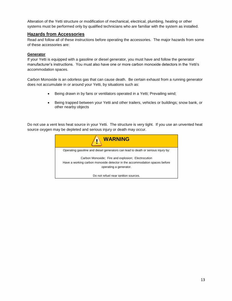
Generator
If your Yetti is equipped with a gasoline or diesel generator, you must have and follow the generator
manufacturer’s instructions. You must also have one or more carbon monoxide detectors in the Yetti's
accommodation spaces.
Carbon Monoxide is an odorless gas that can cause death. Be certain exhaust from a running generator
does not accumulate in or around your Yetti, by situations such as:
Being drawn in by fans or ventilators operated in a Yetti; Prevailing wind;
Being trapped between your Yetti and other trailers, vehicles or buildings; snow bank, or other nearby objects
Do not use a vent less heat source in your Yetti. The structure is very tight. If you use an unvented heat
source oxygen may be depleted and serious injury or death may occur.
Operating gasoline and diesel generators can lead to death or serious injury by:
Carbon Monoxide; Fire and explosion; Electrocution
Have a working carbon monoxide detector in the accommodation spaces before
operating a generator.
Do not refuel near ignition sources.
WARNING

14
LP Gas Fuel System
Risk of death due to fire or explosion
Only connect an LP gas system to a supply of LP gas, NOT natural gas.
Do not store LP gas tanks inside the trailer.
Only fill an LP gas tank 80% full.
Only fill the tank with LP gas (butane or propane)
Overfilled tanks can release gas and cause an explosion.
WARNING
Risk of fire or explosion
If LP gas is detected (by smell or the LP Gas detector):
Do not touch electrical switches
Extinguish flames and pilot lights
Open doors for ventilation
Shut off LP gas supply at the LP tank
Leave the area until odor clears
Correct the source of LP gas leakage before using LP appliances
Do Not Use a Flame to Locate the source of an LP Gas Leak
WARNING
Risk of fire or explosion
Never use a flame, heat lamp or hair dryer to thaw an LP Gas regulator. Use an
incandescent light bulb.
Do not remove the regulator cover or attempt to service the LP Gas regulator.
WARNING
You can die or be brain damaged by Carbon Monoxide
Make certain that the exhaust from LP appliances is directed to the outdoors
Have a working carbon monoxide detector in the accommodation spaces of your trailer
before operating an LP gas appliance. Do not operate portable grills or stoves inside the
trailer
WARNING

15
Safety Warning Labels on Your Yetti
Yetti Towing Guide
Driving a vehicle with a Yetti in tow is vastly different from driving the same vehicle without one in tow.
Acceleration, maneuverability and braking are all diminished with a Yetti in tow. It takes longer to get up
to speed; you need more room to turn and pass, and more distance to stop when towing. You will need
to spend time adjusting to the different feel and maneuverability of the tow vehicle with a loaded Yetti.
Because of the significant differences in all aspects of maneuverability when towing, the hazards and
risks of injury are also much greater than when driving without a Yetti. You are responsible for keeping
your vehicle and Yetti in control, and for all the damage that is caused if you lose control of your vehicle
and Yetti.
As you did when learning to drive an automobile, find an open area with little or no traffic for your first
practice Yetti towing. Of course, before you start towing the Yetti, you must follow all of the instructions
for inspection, testing, loading and coupling. Also, before you start towing, adjust the mirrors so you can
see the Yetti as well as the area to the rear of it.
Drive slowly at first, 5 mph or so, and turn the wheel to get the feel of how the tow vehicle and Yetti
combination responds. Next, make some right and left hand turns. Watch in your side mirrors to see how
the Yetti follows the tow vehicle. Turning with a Yetti attached requires more room.
To protect you and others against death or serious injury, all of the labels shown above
must be on the trailer and must be legible.
If any of these labels are missing or cannot be read, call Voyager Industries at
800-980-4840 for replacement labels.
WARNING

16
Stop the rig a few times from speeds no greater than 10 mph. If your Yetti is equipped with brakes, try
using different combinations of Yetti/electric brake and tow vehicle brake. Note the effect that the Yetti
brakes have when they are the only brakes used. When properly adjusted, the Yetti brakes will come on
just before the tow vehicle brakes.
It will take practice to learn how to back up a tow vehicle with a Yetti attached. Take it slow. Before
backing up, get out of the tow vehicle and look behind the Yetti to make sure that there are no obstacles.
Some drivers place their hands at the bottom of the steering wheel, and while the tow vehicle is in
reverse, “think” of the hands as being on the top of the wheel. When the hands move to the right
(counter-clockwise, as you would do to turn the tow vehicle to the left when moving forward), the rear of
the Yetti moves to the right. Conversely, rotating the steering wheel clockwise with your hands at the
bottom of the wheel will move the rear of the Yetti to the left, while backing up. If you are towing a
bumper hitch rig, be careful not to allow the Yetti to turn too much, because it will hit the rear of the tow
vehicle. To straighten the rig, either pull forward, or turn the steering wheel in the opposite direction.
Reporting Safety Defects If you believe that your vehicle has a defect that could cause a crash or could cause injury or death, you
should immediately inform the National Highway Traffic Safety Administration (NHTSA) in addition to
notifying Voyager Industries Inc.
If NHTSA receives similar complaints, it may open an investigation, and if it finds that a safety defect
exists in a group of vehicles, it may order a recall and remedy campaign. However, NHTSA cannot
become involved in individual problems between you, your dealer, or Voyager Industries.
To contact NHTSA, you may either call the Vehicle Safety Hotline toll-free at 1-888-327-4236 (TTY: 1-
800-424-9153), go tohttp://www.safecar.gov; or write to: Administrator, NHTSA, 1200 New Jersey Ave.
SE., Washington, DC 20590. You can also obtain other information about motor vehicle safety from
http://www.safecar.gov.
17
Safe Yetti Towing Guidelines
Recheck the load tie downs to make sure the load will not shift during towing.
Before towing, check coupling, safety chain, safety brake, tires, wheels and lights.
Check the lug nuts or bolts for tightness.
Check coupler tightness after towing 50 miles.
Use your mirrors to verify that you have room to change lanes or pull into traffic.
Use your turn signals well in advance.
Allow plenty of stopping space for your trailer and tow vehicle.
Do not drive so fast that the trailer begins to sway due to speed. Generally never drive faster than 55 m.p.h.
Allow plenty of room for passing. A rule of thumb is that the passing distance can be 4 times the passing distance without towing a Yetti.
Shift your automatic transmission into a lower gear for city driving.
Use lower gears for climbing and descending grades.
Do not ride the brakes while descending grades, they may get so hot that they stop working. Then you will potentially have a runaway tow vehicle and Yetti.
To conserve fuel, don't use full throttle to climb a hill. Instead, build speed on the approach.
Slow down for bumps in the road. Take your foot off the brake when crossing the bump.
Do not brake while in a curve unless absolutely necessary. Instead, slow down before you enter the curve.
Do not apply the tow vehicle brakes to correct extreme Yetti swaying. Instead, lightly apply the trailer brakes with the hand controller.
Make regular stops, about once each hour.
Confirm that the coupler is secure to the hitch and is locked,
Electrical connectors are made.
There is appropriate slack in the safety chains.
There is appropriate slack in the breakaway switch pull pin cable.
The tires are not visibly low on pressure.
The cargo is secure and in good condition.
If the coupler cannot be secured to the hitch ball, do not tow the trailer
Tire Safety Information This portion of the User’s Manual contains tire safety information as required by 49 CFR 575.6.
“Steps for Determining Correct Load Limit - Trailer”.
“Steps for Determining Correct Load Limit – Tow Vehicle”.
Information from the NHTSA brochure entitled “Tire Safety – Everything Rides On It”.
This brochure describes the following items;
Tire labeling, including a description and explanation of each marking on the tires, and information about the DOT Tire Identification Number (TIN).
Recommended tire inflation pressure, including a description and explanation of: o Cold inflation pressure. o Vehicle Placard and location on the vehicle. o Adverse safety consequences of under inflation (including tire failure). o Measuring and adjusting air pressure for proper inflation.
Tire Care, including maintenance and safety practices.
Vehicle load limits, including a description and explanation of the following items: o Locating and understanding the load limit information, total load capacity, and cargo
capacity.

18
o Calculating total and cargo capacities with varying seating configurations including quantitative examples showing / illustrating how the vehicles cargo and luggage capacity decreases as combined number and size of occupants’ increases. This item is also discussed in Section 3.
o Determining compatibility of tire and vehicle load capabilities. o Adverse safety consequences of overloading on handling and stopping on tires.
Steps for Determining Correct Load Limit - Yetti
Trailers 10,000 Pounds GVWR or Less
Locate the statement, “The weight of cargo should never exceed XXX kg or XXX lbs.,” on your vehicle’s placard. See figure below. This figure equals the available amount of cargo and luggage load capacity.
Determine the combined weight of luggage and cargo being loaded on the vehicle. That weight may not safely exceed the available cargo and luggage load capacity.
The trailer’s placard refers to the Tire Information Placard attached adjacent to or near the trailer’s VIN
(Certification) label at the left front of the trailer.
Steps for Determining Correct Load Limit – Tow Vehicle Locate the statement, “The combined weight of occupants and cargo should never exceed XXX lbs.,” on your vehicle’s placard. Determine the combined weight of the driver and passengers who will be riding in your vehicle.
Subtract the combined weight of the driver and passengers from XXX kilograms or XXX pounds.
The resulting figure equals the available amount of cargo and luggage capacity. For example, if the “XXX” amount equals 1400 lbs. and there will be five 150 lb. passengers in your vehicle, the amount of available cargo and luggage capacity is 650 lbs. (1400-750 (5 x 150) = 650 lbs.).
Determine the combined weight of luggage and cargo being loaded on the vehicle. That weight may not safely exceed the available cargo and luggage capacity calculated in Step # 4.
If your vehicle will be towing a trailer, load from your trailer will be transferred to your vehicle. Consult the
tow vehicle’s manual to determine how this weight transfer reduces the available cargo and luggage
capacity of your vehicle

19
Tire Safety - Everything Rides On It
The National Traffic Safety Administration (NHTSA) has published a brochure (DOT HS 809 361) that
discusses all aspects of Tire Safety, as required by CFR 575.6. This brochure is reproduced in part
below. It can be obtained and downloaded from NHTSA, free of charge, from the following web site:
http://www.nhtsa.dot.gov/cars/rules/TireSafety/ridesonit/tires_index.html
Studies of tire safety show that maintaining proper tire pressure, observing tire and vehicle load limits (not
carrying more weight in your vehicle than your tires or vehicle can safely handle), avoiding road hazards,
and inspecting tires for cuts, slashes, and other irregularities are the most important things you can do to
avoid tire failure, such as tread separation or blowout and flat tires. These actions, along with other care
and maintenance activities, can also:
Improve vehicle handling
Help protect you and others from avoidable breakdowns and accidents
Improve fuel economy
Increase the life of your tires
This booklet presents a comprehensive overview of tire safety, including information on the following
topics:
Basic tire maintenance
Uniform Tire Quality Grading System
Fundamental characteristics of tires
Tire safety tips
Use this information to make tire safety a regular part of your vehicle maintenance routine. Recognize
that the time you spend is minimal compared with the inconvenience and safety consequences of a flat
tire or other tire failure.
Safety First–Basic Tire Maintenance Properly maintained tires improve the steering, stopping, traction, and load-carrying capability of your
vehicle. Underinflated tires and overloaded vehicles are a major cause of tire failure. Therefore, as
mentioned above, to avoid flat tires and other types of tire failure, you should maintain proper tire
pressure, observe tire and vehicle load limits, avoid road hazards, and regularly inspect your tires.
Finding Your Vehicle's Recommended Tire Pressure and Load Limits
Tire information placards and vehicle certification labels contain information on tires and load limits.
These labels indicate the vehicle manufacturer's information including:
Recommended tire size Recommended tire inflation pressure Vehicle capacity weight (VCW–the maximum occupant and cargo weight a vehicle is designed to carry) Front and rear gross axle weight ratings (GAWR– the maximum weight the axle systems are designed to carry).
Both placards and certification labels are permanently attached to the trailer near the left front.

20
Understanding Tire Pressure and Load Limits Tire inflation pressure is the level of air in the tire that provides it with load-carrying capacity and affects
the overall performance of the vehicle. The tire inflation pressure is a number that indicates the amount of
air pressure– measured in pounds per square inch (psi)–a tire requires to be properly inflated. (You will
also find this number on the vehicle information placard expressed in kilopascals (kPa), which is the
metric measure used internationally.)
Manufacturers of passenger vehicles and light trucks determine this number based on the vehicle's
design load limit, that is, the greatest amount of weight a vehicle can safely carry and the vehicle's tire
size. The proper tire pressure for your vehicle is referred to as the "recommended cold inflation
pressure." (As you will read below, it is difficult to obtain the recommended tire pressure if your tires are
not cold.)
Because tires are designed to be used on more than one type of vehicle, tire manufacturers list the
"maximum permissible inflation pressure" on the tire sidewall. This number is the greatest amount of air
pressure that should ever be put in the tire under normal driving conditions.
Checking Tire Pressure It is important to check your vehicle's tire pressure at least once a month for the following reasons:
Most tires may naturally lose air over time. Tires can lose air suddenly if you drive over a pothole or other object or if you strike the curb when parking. With radial tires, it is usually not possible to determine under inflation by visual inspection.
For convenience, purchase a tire pressure gauge to keep in your vehicle. Gauges can be purchased at
tire dealerships, auto supply stores, and other retail outlets.
The recommended tire inflation pressure that vehicle manufacturers provide reflects the proper psi when
a tire is cold. The term cold does not relate to the outside temperature. Rather, a cold tire is one that has
not been driven on for at least three hours. When you drive, your tires get warmer, causing the air
pressure within them to increase. Therefore, to get an accurate tire pressure reading, you must measure
tire pressure when the tires are cold or compensate for the extra pressure in warm tires.
Steps for Maintaining Proper Tire Pressure Step 1: Locate the recommended tire pressure on the vehicle's tire information placard, certification label,
or in the owner's manual. Step 2: Record the tire pressure of all tires. Step 3: If the tire pressure is too high in any of the tires, slowly release air by gently pressing on the tire
valve stem with the edge of your tire gauge until you get to the correct pressure. Step 4: If the tire pressure is too low, note the difference between the measured tire pressure and the
correct tire pressure. These "missing" pounds of pressure are what you will need to add. Step 5: At a service station, add the missing pounds of air pressure to each tire that is underinflated. Step 6: Check all the tires to make sure they have the same air pressure (except in cases in which the
front and rear tires are supposed to have different amounts of pressure).
If you have been driving your vehicle and think that a tire is underinflated, fill it to the recommended cold
inflation pressure indicated on your vehicle's tire information placard or certification label. While your tire
may still be slightly underinflated due to the extra pounds of pressure in the warm tire, it is safer to drive
with air pressure that is slightly lower than the vehicle manufacturer's recommended cold inflation
pressure than to drive with a significantly underinflated tire. Since this is a temporary fix, don't forget to
recheck and adjust the tire's pressure when you can obtain a cold reading.
21
Tire Size To maintain tire safety, purchase new tires that are the same size as the vehicle's original tires or another
size recommended by the manufacturer. Look at the tire information placard, the owner's manual, or the
sidewall of the tire you are replacing to find this information. If you have any doubt about the correct size
to choose, consult with the tire dealer.
Tire Tread The tire tread provides the gripping action and traction that prevent your vehicle from slipping or sliding,
especially when the road is wet or icy. In general, tires are not safe and should be replaced when the
tread is worn down to 1/16 of an inch. Tires have built-in tread wear indicators that let you know when it is
time to replace your tires. These indicators are raised sections spaced intermittently in the bottom of the
tread grooves. When they appear "even" with the outside of the tread, it is time to replace your tires.
Another method for checking tread depth is to place a penny in the tread with Lincoln's head upside down
and facing you. If you can see the top of Lincoln's head, you are ready for new tires.
Tire Balance and Wheel Alignment
To avoid vibration or shaking of the vehicle when a tire rotates, the tire must be properly balanced. This
balance is achieved by positioning weights on the wheel to counterbalance heavy spots on the wheel-
and-tire assembly. A wheel alignment adjusts the angles of the wheels so that they are positioned
correctly relative to the vehicle's frame. This adjustment maximizes the life of your tires. These
adjustments require special equipment and should be performed by a qualified technician.
Tire Repair
The proper repair of a punctured tire requires a plug for the hole and a patch for the area inside the tire
that surrounds the puncture hole. Punctures through the tread can be repaired if they are not too large,
but punctures to the sidewall should not be repaired. Tires must be removed from the rim to be properly
inspected before being plugged and patched.
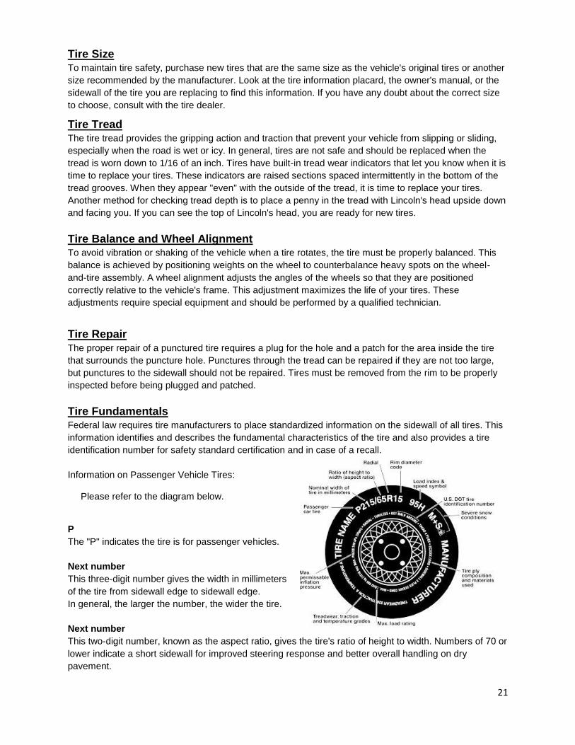
Tire Fundamentals Federal law requires tire manufacturers to place standardized information on the sidewall of all tires. This
information identifies and describes the fundamental characteristics of the tire and also provides a tire
identification number for safety standard certification and in case of a recall.
Information on Passenger Vehicle Tires: Please refer to the diagram below.
P
The "P" indicates the tire is for passenger vehicles.
Next number
This three-digit number gives the width in millimeters
of the tire from sidewall edge to sidewall edge.
In general, the larger the number, the wider the tire.
Next number
This two-digit number, known as the aspect ratio, gives the tire's ratio of height to width. Numbers of 70 or
lower indicate a short sidewall for improved steering response and better overall handling on dry
pavement.

22
R
The "R" stands for radial. Radial ply construction of tires has been the industry standard for the past 20
years.
Next number
This two-digit number is the wheel or rim diameter in inches. If you change your wheel size, you will have
to purchase new tires to match the new wheel diameter.
Next number
This two- or three-digit number is the tire's load index. It is a measurement of how much weight each tire
can support. You may find this information in your owner's manual. If not, contact a local tire dealer. Note:
You may not find this information on all tires because it is not required by law.
M+S
The "M+S" or "M/S" indicates that the tire has some mud and snow capability. Most radial tires have
these markings; hence, they have some mud and snow capability.
U.S. DOT Tire Identification Number
This begins with the letters "DOT" and indicates that the tire meets all federal standards. The next two
numbers or letters are the plant code where it was manufactured, and the last four numbers represent the
week and year the tire was built. For example, the numbers 3197 means the 31st week of 1997. The
other numbers are marketing codes used at the manufacturer's discretion. This information is used to
contact consumers if a tire defect requires a recall.
Tire Ply Composition and Materials Used
The number of plies indicates the number of layers of rubber-coated fabric in the tire. In general, the
greater the number of plies, the more weight a tire can support. Tire manufacturers also must indicate the
materials in the tire, which include steel, nylon, polyester, and others.
Maximum Load Rating
This number indicates the maximum load in kilograms and pounds that can be carried by the tire.
Maximum Permissible Inflation Pressure
This number is the greatest amount of air pressure that should ever be put in the tire under normal driving
conditions.
UTQGS Information Tread wear Number This number indicates the tire's wear rate. The higher the tread wear number is, the longer it should take for the tread to wear down. For example, a tire graded 400 should last twice as long as a tire graded 200.
Traction Letter
This letter indicates a tire's ability to stop on wet pavement. A higher graded tire should allow you to stop
your car on wet roads in a shorter distance than a tire with a lower grade. Traction is graded from highest
to lowest as "AA","A", "B", and "C".
23
Temperature Letter
This letter indicates a tire's resistance to heat. The temperature grade is for a tire that is inflated properly
and not overloaded. Excessive speed, under inflation or excessive loading, either separately or in
combination, can cause heat build-up and possible tire failure. From highest to lowest, a tire's resistance
to heat is graded as "A", "B", or "C".
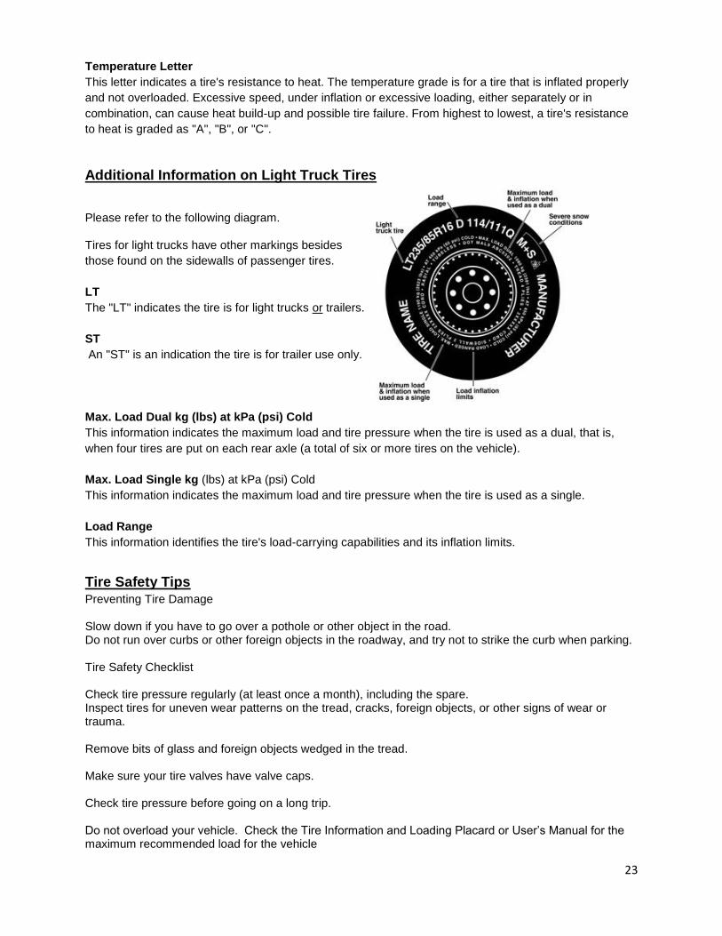
Additional Information on Light Truck Tires
Please refer to the following diagram.
Tires for light trucks have other markings besides
those found on the sidewalls of passenger tires.
LT
The "LT" indicates the tire is for light trucks or trailers.
ST
An "ST" is an indication the tire is for trailer use only.
Max. Load Dual kg (lbs) at kPa (psi) Cold
This information indicates the maximum load and tire pressure when the tire is used as a dual, that is,
when four tires are put on each rear axle (a total of six or more tires on the vehicle).
Max. Load Single kg (lbs) at kPa (psi) Cold
This information indicates the maximum load and tire pressure when the tire is used as a single.
Load Range
This information identifies the tire's load-carrying capabilities and its inflation limits.
Tire Safety Tips Preventing Tire Damage Slow down if you have to go over a pothole or other object in the road. Do not run over curbs or other foreign objects in the roadway, and try not to strike the curb when parking. Tire Safety Checklist Check tire pressure regularly (at least once a month), including the spare. Inspect tires for uneven wear patterns on the tread, cracks, foreign objects, or other signs of wear or trauma. Remove bits of glass and foreign objects wedged in the tread. Make sure your tire valves have valve caps. Check tire pressure before going on a long trip. Do not overload your vehicle. Check the Tire Information and Loading Placard or User’s Manual for the maximum recommended load for the vehicle

24
Trailer Information—Certification / VIN Label
Certification / VIN tag contains the following, critical, safety information for the use of your trailer:
MANUFACTURER: Name of trailer manufacturer
DATE OF MANUFACTURE: Month and year
the trailer was manufactured.
GVWR: The Gross Vehicle Weight Rating is the maximum allowable gross weight of the trailer and its
contents. The gross weight of the trailer includes the weight of the trailer and all of the items within it
(such as cargo, water, food and other supplies).
GAWR: The Gross Axle Weight Rating is the maximum gross weight that an axle can support. It is the
lowest of axle, wheel, or tire rating. Sometimes the tire or wheel rating is lower than the axle
manufacturers rating, and will then determine GAWR.
The sum total of the GAWR for all trailer axles may be less than the GVWR for the trailer, because some
of the trailer load is carried by the tow vehicle, rather than by the trailer axle(s). The total weight of the
cargo and trailer must not exceed the GVWR, and the load on an axle must not exceed its GAWR.
TIRE SIZE: The tire size recommended for your trailer and load range.
PSIC: The “pounds per square inch- cold” is the tire pressure (Kilopascals / Pounds per Square Inch)
measured when Cold.
CERTIFICATION STATEMENT: “This trailer meets all the Federal Motor Vehicle Safety Standards in
effect on the date of manufacture shown above”.
VIN: The Vehicle Identification Number.
VEHICLE TYPE: Generally the word “trailer” is used. However, after this you may put a Model #, or
additional descriptor.

25
Definitions
Tow Vehicle: When equipping a new vehicle or an older vehicle to tow your trailer, ask the vehicle dealer
for advice on how to outfit the towing vehicle. Discuss the following information and equipment with the
vehicle dealer.
Overall Carrying and Towing Capacity of Vehicle: Vehicle manufacturers will provide you with the
maximum towing capacities of their various models, as well as the GCWR. No amount of reinforcement
will give a 100 horsepower, 2,500 pound truck the towing capacity that a 300 horsepower, 5,000 pound
truck has.
Towing Hitch: The towing hitch attached to your tow vehicle must have a capacity equal to or greater
than the load rating of the trailer you intend to tow. The hitch capacity must also be matched to the tow
vehicle capacity.
Brake Controller: The brake controller is part of the tow vehicle and is essential in the operation of the
electric brakes on the trailer. If your trailer has electric brakes it requires a brake controller be installed at
the driver’s position. The brake controller is not the same as the safety breakaway brake system that is
installed on the trailer.
Side View Mirrors: The size of the trailer that is being towed and your state law regulations determine
the size of the mirrors. However, some states prohibit extended mirrors on a tow vehicle, except while a
trailer is actually being towed. In this situation, detachable extended mirrors are necessary. Check with
your dealer or the appropriate state agency for mirror requirements.
Heavy Duty Flasher: A Heavy Duty Flasher is an electrical component that may be required when your
trailer turn signal lights are attached to the tow vehicle flasher circuit.
Electrical Connector: An Electrical Connector connects the light and brake systems on the trailer to the
light and brake controls on the towing vehicle.
Fire Extinguisher: It is sensible to have a fire extinguisher in the tow vehicle.
Emergency Flares and Emergency Triangle Reflectors: It is wise to carry these warning devices even
if you are not towing a trailer. It is particularly important to have these when towing a trailer because the
hazard flashers of your towing vehicle will not operate for as long a period of time when the battery is
running both the trailer lights and tow vehicle lights.
Jack: A device on the trailer that is used to raise and lower the trailer tongue. On larger trailers the jack is
sometimes called the “landing gear.”

26
Lowering Your Manual Yetti
When lowering, it is recommended to use a surface that is as flat and level as possible. You may lower
your Yetti onto blocks to accomplish this. Increased pressure (side pressure) on the frame structure will
cause the safety pins to be difficult to remove. Side pressure can be caused by the use of tongue jacks;
uneven ground; and tow vehicles that are not in line with the Yetti
Start the lowering process at the tongue. With the ratchet lever engaged, slightly rotate the winch until the
top pin is loose. Remove the safety clip and pin. Move the ratchet lever to its downward position. Do not
lose control, while unwinding the winch until the front of the fish house has been fully lowered.
Move to the driver’s side wheel assembly, and ensure that the ratchet is engaged by moving the ratchet
lever to its upward position. Wind the winch until there is no pressure on the leaf spring/shackle and make
sure the pin is loose. Remove the safety clip and pin. Move the ratchet lever to its downward position. Do
not lose control while unwinding the winch. Continue until the Yetti is approximately half-way down.
Engage ratchet by moving ratchet lever to its upward position.
Move to passenger’s side wheel assembly, and ensure that the ratchet is engaged by moving the ratchet
lever to its upward position. Wind the winch until there is no pressure on the leaf spring/shackle and make
sure the pin is loose. Remove the safety clip and pin. Move the ratchet lever to its downward position. Do
not lose control while unwinding the winch. Continue until the Yetti is on the surface
Move back to the driver’s side wheel assembly. Move the ratchet lever to its downward position Do not
lose control while unwinding the winch. Continue until the Yetti is on the surface
If you wish to uncouple your Yetti from the vehicle; remove the safety chains, unplug the trailer lights and
remove the coupler (see coupler instructions).
When lowering or raising, make sure your hands and feet are not under the fish house!
WARNING
If you should lose control of the winch handle during the raising or lowering process DO
NOT try to catch or stop the freewheeling winch handle. Serious bodily injury may occur.
Allow the handle to spin freely until the Yetti is completely lowered to the ground or ice.
WARNING
DANGER
27
Raising Your Manual Yetti
Start the raising process at the tongue. Connect the coupler to the tow vehicle. Do not raise the front at
this time.
Move to the driver’s side wheel assembly, and ensure that the ratchet is engaged by moving the ratchet
lever to its upward position. Review that the cable is correctly positioned on the cable rollers. Wind the
winch until the Yetti is half way raised
Move to passenger’s side wheel assembly, and ensure that the ratchet is engaged by moving the ratchet
lever to its upward position. Review that the cable is correctly positioned on the cable rollers. Wind the
winch until the holes in the shackle and leaf spring line up. Insert the safety pin and safety clip. Move
the ratchet lever to the downward position and unwind the winch until there is no pressure on the
cables. You need to leave enough slack in the cables to pinch them together. Move the ratchet
lever to the upward position for towing.
Move back to the driver side wheel assembly and complete the raising process as you did on the
passenger’s side.
Move back to the tongue. Wind the winch until the top pin holes line up. Insert the safety pin and clip.
Move the ratchet lever to the downward position and slightly unwind the winch to produce a small amount
of slack in the cable. Reconnect the safety chains; light connection; brake connections (as needed) and
engage the coupler locking mechanism. In the engaged position, the locking mechanism securely holds
the coupler to the hitch ball.
Insert a pin or lock through the hole in the locking mechanism.
Be sure the coupler is all the way on the hitch ball and the locking mechanism is engaged.

28
29
Lowering Your Hydraulic Yetti
When lowering, it is recommended to use a surface that is as flat and level as possible. You may lower your Yetti onto blocks to accomplish this. Increased pressure (side pressure) on the frame structure will cause the safety pins to be difficult to remove. Side pressure can be caused by the use of tongue jacks; uneven ground; and tow vehicle that are not in line with the Yetti
1) Turn on the wireless remote by pressing the red power button until both indicator lights flash. a) Green LED will flash rapidly when communication is established. The LED will blink slowly if the
receiver is off or there is no communication. b) The Red LED is for diagnostics and battery. The LED will blink once every second when the battery is
low and requires charging. It also blinks when there is a problem with the system in the form of an error code. Refer to the Wireless Remote ERROR CODE CHART table for more information.
Note: To check for low battery, turn the receiver off and leave the transmitter on. If the red LED continues
to blink, the battery is low and requires charging. If the red LED blinks only when the receiver is on, count the number of blinks and refer to the ERROR CODE CHART tables for additional information. Note: Transmitters will stay on as long as the receiver is on, then turn off automatically ten minutes after
the receiver is turned off, in order to save power.
2) Starting at the tongue, remove the safety clip and pin. You may need to use the Tongue Raise/Lower buttons to remove pressure from the pin. Unlock the coupler from the tow vehicle.
3) Move to the driver’s (left) side wheel assembly. Remove the safety clip and pin. You may need to
use the Left Raise/Lower buttons to remove pressure from the pin.
4) Move to passenger’s (right) side wheel assembly. Remove the safety clip and pin. You may need to use the Right Raise/Lower buttons to remove pressure from the pin.
5) Press and hold the Lower All button until the Yetti is on the surface.
Raising Your Hydraulic Yetti
1) Turn on the wireless remote.
2) Press and hold the Raise All button until the Yetti is fully raised.
3) Start at the driver’s (left) side wheel assembly. Insert the safety pin and clip. You may need to use the Left Raise/Lower buttons to line up the holes to insert the pin.
4) Move to the passenger’s (right) side wheel assembly. Insert the safety pin and clip. You may need to use the Right Raise/Lower buttons to line up the holes to insert the pin.
5) Finish at the tongue, you may need to use the Tongue Raise/Lower Buttons to line up the holes to insert the pin. Insert the safety pin and clip. Be sure the coupler is all the way on the hitch ball and the locking mechanism is engaged.
6) After all safety pins and clips are installed, press and hold the Lower All button until the Yetti is resting on the pins.
When lowering or raising, make sure your hands and feet are not under the fish house!
WARNING DANGER
30
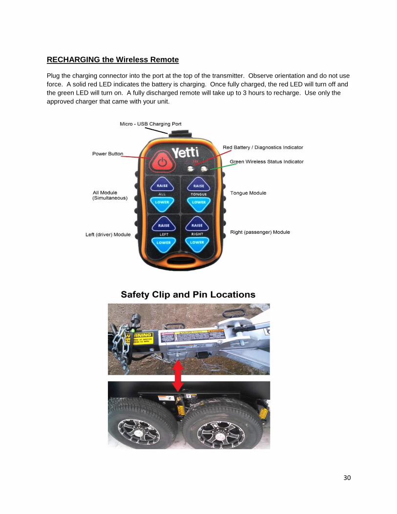
RECHARGING the Wireless Remote
Plug the charging connector into the port at the top of the transmitter. Observe orientation and do not use
force. A solid red LED indicates the battery is charging. Once fully charged, the red LED will turn off and
the green LED will turn on. A fully discharged remote will take up to 3 hours to recharge. Use only the
approved charger that came with your unit.

31
LOADING THE YETTI
Improper trailer loading causes many accidents and deaths. To safely load a trailer, you must consider:
Overall load weight; Load weight distribution;
Proper tongue weight; and Securing the load properly.
To determine that you have loaded the trailer within its rating, you must consider the distribution of
weight, as well as the total weight of the trailer and its contents. The trailer axles carry most of the total
weight of the trailer and its contents (Gross Vehicle Weight, or “GVW”). The remainder of the total weight
is carried by the tow vehicle hitch. It is essential for safe towing that the trailer-tongue and tow vehicle
hitch carry the proper amount of the loaded trailer weight, otherwise the trailer can develop an
undesirable sway at towing speeds, or the rear of the towing vehicle can be overloaded. Read the
“Tongue Weight” section below.
The load distribution must be such that no component part of the trailer is loaded beyond its rating. This
means that you must consider the rating of the tires, wheels and axles. For tandem and triple axle
trailers, you must make sure that the front-to-rear load distribution does not result in overloading any axle.
Towing stability also depends on keeping the center of gravity as low as possible. Load heavy items on
the floor and over the axles. When loading additional items, be sure to maintain even side-to-side weight
distribution and proper tongue weight. The total weight of the trailer and its contents must never exceed
the total weight rating of the trailer (Gross Vehicle Weight Rating, or the Gross Axle Weight Rating)
Tongue Weight It is critical to have a portion of the trailer load carried by the tow vehicle. That is, the trailer tongue must
exert a downward force on the hitch. This is necessary for two reasons. First, the proper amount of
tongue weight is necessary for the tow vehicle to be able to maintain control of the tow vehicle/trailer
system. If, for example, the tongue exerts an upward pull on the hitch, instead of pushing down on it
(because the trailer is overloaded behind its axle(s), the rear wheel of the tow vehicle can lose traction or
grip and cause loss of control. Also, even if there is some weight on the tongue, but not enough weight
on the tongue, the trailer can become unstable at high speeds. Remember, the faster you go the more
likely the trailer is to sway.
If, on the other hand, there is too much tongue weight, the tow vehicle is prone to jack-knife. Furthermore,
the front wheels of the tow vehicle can be too lightly loaded and cause loss of steering control and
traction, if the front wheels are driving.
In addition to tow vehicle control, tongue weight is necessary to insure that the trailer axle(s) do not
exceed their Gross Axle Weight Rating (GAWR).
An overloaded trailer can result in loss of control of the trailer, leading to death or serious injury.
Do not exceed the trailer Gross Vehicle Weight Rating (GVWR) or the Gross Axle Weight
Rating (GAWR). Do not load the trailer so that the weight on any tire exceeds its rating.
WARNING

32
The table below has “rules of thumb” for proper tongue weight.
In the table below, the second column notes the rule of thumb percentage of total weight of the trailer plus
its cargo (Gross Vehicle Weight, or “GVW”) that should appear on the tongue of the trailer. For example,
a trailer with a gooseneck hitch, with a loaded weight of 12,000 pounds, should have 20-25% (of 12,000
pounds) on the tongue. That is, the example trailer would have 2,400 to 3,000 pounds on its tongue.
Tongue Weight as a Percentage of Loaded Trailer Weight
Type of Hitch Percentage
Ball Hitch (or Bumper Hitch) 10–15%for large trailers
6-10% for smaller utility and cargo trailers
The numbers quoted above are for example purposes only and should be tailored to the specific trailer.
For questions regarding the actual percent of tongue weight for the trailer, check with the manufacturer
for specifics.
For heavier trailers it is easier to go to a truck stop where there is a “certified” scale. Pull only the tow
vehicle onto the scale and get the weight. This weight must be less than your tow vehicle’s GVWR. Pull
the trailer onto the scale and decouple it from the tow vehicle, leaving just the trailer on the scale. Get a
“ticket”, which lists the total trailer weight. Re-connect the trailer to your tow vehicle and the drive the tow
vehicle wheels off the scale, just leaving the trailer axles on the scale. Get a second “ticket”, which lists
the trailer’s axle weight. Simple subtract the axle weight from the total weight to determine the hitch
weight.
While you are at the scale, you should weigh the entire combination vehicle. This result should be less
than the Gross Combined Weight Rating (GCWR) for your towing vehicle. Some scales allow you to get
individual axle weights also. If this is possible, get the tow vehicles front and rear axle weights to make
sure they are in the same proportion as the tow vehicle alone, and that the rear axle is not overloaded.
This is the best way to check that a weight distribution (or load leveling) hitch is adjusted properly, i.e.,
you have the proper number of chain links attached to the snap-up brackets.
Improper tongue weight (load distribution) can result in loss of control of the trailer, leading to
death or serious injury.
Make certain that the tongue weight is within allowable range.
Be sure to:
Distribute the load front-to-rear to provide proper tongue weight (see chart)
Distribute the load evenly right and left to avoid tire overload, and keep the center of gravity low.
WARNING
33
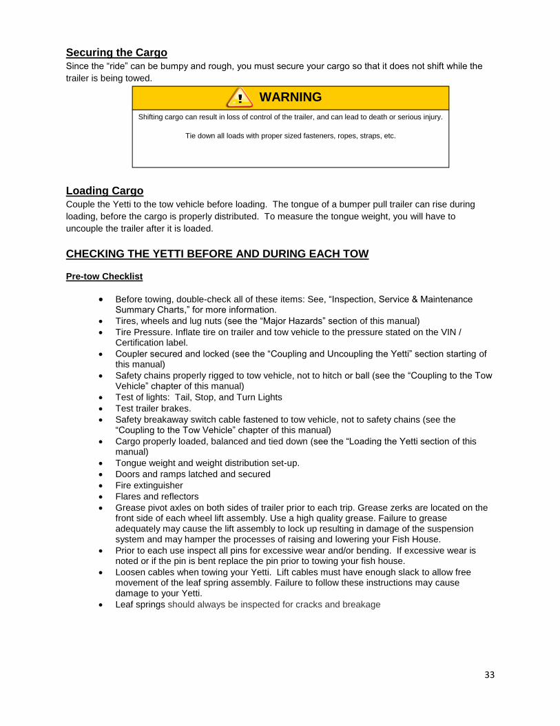
Securing the Cargo
Since the “ride” can be bumpy and rough, you must secure your cargo so that it does not shift while the
trailer is being towed.
Loading Cargo
Couple the Yetti to the tow vehicle before loading. The tongue of a bumper pull trailer can rise during
loading, before the cargo is properly distributed. To measure the tongue weight, you will have to
uncouple the trailer after it is loaded.
CHECKING THE YETTI BEFORE AND DURING EACH TOW
Pre-tow Checklist
Before towing, double-check all of these items: See, “Inspection, Service & Maintenance Summary Charts,” for more information.
Tires, wheels and lug nuts (see the “Major Hazards” section of this manual)
Tire Pressure. Inflate tire on trailer and tow vehicle to the pressure stated on the VIN / Certification label.
Coupler secured and locked (see the “Coupling and Uncoupling the Yetti” section starting of this manual)
Safety chains properly rigged to tow vehicle, not to hitch or ball (see the “Coupling to the Tow Vehicle” chapter of this manual)
Test of lights: Tail, Stop, and Turn Lights
Test trailer brakes.
Safety breakaway switch cable fastened to tow vehicle, not to safety chains (see the “Coupling to the Tow Vehicle” chapter of this manual)
Cargo properly loaded, balanced and tied down (see the “Loading the Yetti section of this manual)
Tongue weight and weight distribution set-up.
Doors and ramps latched and secured
Fire extinguisher
Flares and reflectors
Grease pivot axles on both sides of trailer prior to each trip. Grease zerks are located on the front side of each wheel lift assembly. Use a high quality grease. Failure to grease adequately may cause the lift assembly to lock up resulting in damage of the suspension system and may hamper the processes of raising and lowering your Fish House.
Prior to each use inspect all pins for excessive wear and/or bending. If excessive wear is noted or if the pin is bent replace the pin prior to towing your fish house.
Loosen cables when towing your Yetti. Lift cables must have enough slack to allow free movement of the leaf spring assembly. Failure to follow these instructions may cause damage to your Yetti.
Leaf springs should always be inspected for cracks and breakage
Shifting cargo can result in loss of control of the trailer, and can lead to death or serious injury.
Tie down all loads with proper sized fasteners, ropes, straps, etc.
WARNING
34
Make Regular Stops
After each 50 miles, or one hour of towing, stop and check the following items:
Coupler secured
Safety chains are fastened and not dragging
Cargo secured
Cargo door latched and secured
BREAKING-IN A NEW TRAILER Retighten Lug Nuts at First 10, 25 & 50 Miles
Wheel lugs can shift and settle quickly after being first assembled, and must be checked after the first 10,
25 and 50 miles of driving. Failure to perform this check may result in a wheel coming loose from the
trailer, causing a crash leading to death or serious injury.
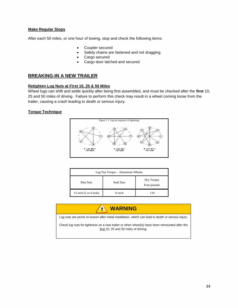
Torque Technique
Figure 7-1 Lug nut sequence of tightening
Lug Nut Torque – Aluminum Wheels
Rim Size Stud Size Dry Torque
Foot-pounds
15 inch (5 or 6 hole) ½ inch 110
Lug nuts are prone to loosen after initial installation, which can lead to death or serious injury.
Check lug nuts for tightness on a new trailer or when wheel(s) have been remounted after the
first 10, 25 and 50 miles of driving.
WARNING
35
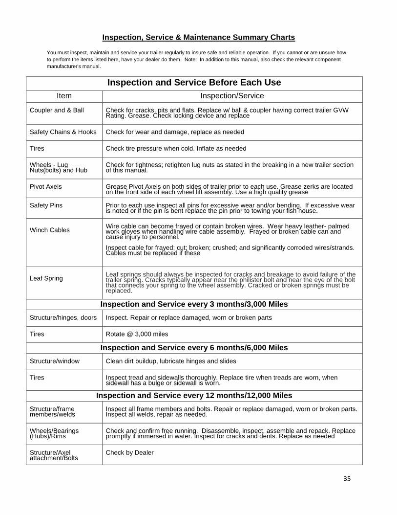
Inspection, Service & Maintenance Summary Charts
You must inspect, maintain and service your trailer regularly to insure safe and reliable operation. If you cannot or are unsure how
to perform the items listed here, have your dealer do them. Note: In addition to this manual, also check the relevant component
manufacturer's manual.
Inspection and Service Before Each Use
Item Inspection/Service Coupler and & Ball
Check for cracks, pits and flats. Replace w/ ball & coupler having correct trailer GVW Rating. Grease. Check locking device and replace
Safety Chains & Hooks
Check for wear and damage, replace as needed
Tires
Check tire pressure when cold. Inflate as needed
Wheels - Lug Nuts(bolts) and Hub
Check for tightness; retighten lug nuts as stated in the breaking in a new trailer section of this manual.
Pivot Axels
Grease Pivot Axels on both sides of trailer prior to each use. Grease zerks are located on the front side of each wheel lift assembly. Use a high quality grease
Safety Pins
Prior to each use inspect all pins for excessive wear and/or bending. If excessive wear is noted or if the pin is bent replace the pin prior to towing your fish house.
Winch Cables
Wire cable can become frayed or contain broken wires. Wear heavy leather- palmed work gloves when handling wire cable assembly. Frayed or broken cable can and cause injury to personnel. Inspect cable for frayed; cut; broken; crushed; and significantly corroded wires/strands. Cables must be replaced if these
Leaf Spring
Leaf springs should always be inspected for cracks and breakage to avoid failure of the trailer spring. Cracks typically appear near the philister bolt and near the eye of the bolt that connects your spring to the wheel assembly. Cracked or broken springs must be replaced.
Inspection and Service every 3 months/3,000 Miles Structure/hinges, doors
Inspect. Repair or replace damaged, worn or broken parts
Tires
Rotate @ 3,000 miles
Inspection and Service every 6 months/6,000 Miles Structure/window
Clean dirt buildup, lubricate hinges and slides
Tires
Inspect tread and sidewalls thoroughly. Replace tire when treads are worn, when sidewall has a bulge or sidewall is worn.
Inspection and Service every 12 months/12,000 Miles Structure/frame members/welds
Inspect all frame members and bolts. Repair or replace damaged, worn or broken parts. Inspect all welds, repair as needed.
Wheels/Bearings (Hubs)/Rims
Check and confirm free running. Disassemble, inspect, assemble and repack. Replace promptly if immersed in water. Inspect for cracks and dents. Replace as needed
Structure/Axel attachment/Bolts
Check by Dealer

36
Inspection and Service Instructions
Axle Bolts, Frame, Suspension, & Structure
YETTI STRUCTURE
Fasteners and Frame Members Inspect all of the fasteners and structural frame members for bending and other damage, cracks, or failure. Repair or replace any damaged fastener and repair the frame member. If you have any questions about the condition or method of repair of fasteners or frame members, get the recommendation of, or have the repair done by, your dealer.
Welds All welds can crack or fail when subjected to heavy loads or movement of cargo that was not properly tied to prevent movement. Any time that you know or suspect that the trailer has been subjected to heavy loads or movement of cargo, immediately inspect the welds and fasteners for damage. To prevent severe damage to your trailer, inspect all of the welds for cracks or failure at least once a year.
Worn or broken suspension parts can cause loss of control and injury may result
Have your trailer professionally inspected annually and after any impact
WARNING
Never crawl under your trailer unless it is on firm and level ground and resting on properly
placed and secured jack stands.
WARNING
Broken or damaged fasteners or welds can cause injury or damage to trailer and contents.
Inspect for, and repair all, damaged parts at least once a year.
WARNING
Improper weld repair will lead to early failure of the trailer structure and can cause serious injury
or death.
Do not repair cracked or broken welds unless you have the skills and equipment to make a
proper repair. If not, have the welds repaired by your dealer.
WARNING

37
Yetti Connection to Tow Vehicle
Coupler and Ball
The coupler on the trailer connects to the ball attached to the hitch on the tow vehicle. The coupler, ball
and hitch transfer the towing forces between the tow vehicle and the trailer. Before each tow, coat the
ball with a thin layer of automotive bearing grease to reduce wear and ensure proper operation; and
check the locking device that secures the coupler to the ball for proper operation.
See the coupler manufacturer’s manual for other inspection and maintenance activities. If you do not
have this manual, call Voyager Industries 800-980-4940 for a free copy.
If you see or feel evidence of wear, such as flat spots, deformations, pitting or corrosion, on the ball or
coupler, immediately have your dealer inspect them to determine the proper action to prevent possible
failure of the ball and coupler system. All bent or broken coupler parts must be replaced before towing the
trailer.
The coupler handle lever must be able to rotate freely and automatically snap into the latched position.
Oil the pivot points, sliding surfaces, and spring ends with SAE 30W motor oil. Keep the ball pocket and
latch mechanism clean. Dirt or contamination can prevent proper operation of the latching mechanism.
When replacing a ball, the load rating must match or exceed the GVWR of the trailer.
Landing Leg or Jack If a grease fitting is present, you must use a grease gun to lubricate the jack mechanism. Grease the gears in the top of hand-cranked jacks once a year, by removing the top of the jack and pumping or hand packing grease into the gears.
Lights and Signals Before each tow, check the trailer taillights, stoplights, turn signals and any clearance lights for proper operation
Tires Trailer tires may be worn out even though they still have plenty of tread left. This is because trailer tires have to carry a lot of weight all the time, even when not in use. It is actually better for the tire to be rolling down the road than to be idle. During use, the tire releases lubricants that are beneficial to tire life. Using the trailer tires often also helps prevent flat spots from developing.
The main cause of tire failure is improper inflation. Check the cold tire inflation pressures at least once a
week for proper inflation levels. “Cold” means that the tires are at the same temperature as the
surrounding air, such as when the vehicle has been parked overnight. Wheel and tire manufacturers
recommend adjusting the air pressure to the trailer manufacturer’s recommended cold inflation pressure,
in pounds per square inch (PSI) stated on the vehicle’s Federal Certification Label or Tire Placard when
the trailer is loaded to its gross vehicle weight rating (GVWR). If the tires are inflated to less than the
recommended inflation level or the GVWR of the trailer is exceeded, the load carrying capacity of the tire
Improperly operating taillights, stoplights and turn signals can cause collisions.
Check all lights before each tow.
WARNING

38
could be dramatically affected. If the tires are inflated more than the recommended inflation level,
handling characteristics of the tow vehicle/trailer combination could be affected. Refer to the owner’s
manual or talk to your dealer or vehicle manufacturer if you have any questions regarding proper inflation
practices.
Tires can lose air over a period of time. In fact, tires can lose 1 to 3 PSI per month. This is because molecules of air, under pressure, weave their way from the inside of the tire, through the rubber, to the outside. A drop in tire pressure could cause the tire to become overloaded, leading to excessive heat build-up. If a trailer tire is under-inflated, even for a short period of time, the tire could suffer internal damage.
High speed towing in hot conditions degrades trailer tires significantly. As heat builds up during driving, the tire’s internal structure starts to breakdown, compromising the strength of the tire. It is recommended to drive at moderate speeds.
Statistics indicate the average life of a trailer tire is about five years under normal use and maintenance conditions. After three years, replacing the trailer tires with new ones should be considered, even if the tires have adequate tread depth. Some experts claim that after five years, trailer tires are considered worn out and should be replaced, even if they have had minimal or no use. This is such a general statement that it may not apply in all cases. It is best to have your tires inspected by a tire supplier to determine if your tires need to be replaced.
If you are storing your trailer for an extended period, make sure the tires are fully inflated to the maximum rated pressure and that you store them in a cool, dry place, such as a garage. Use tire covers to protect the trailer tires from the harsh effects of the sun.
Wheel Rims
If the trailer has been struck, or impacted, on or near the wheels, or if the trailer has struck a curb, inspect
the rims for damage (i.e. being out of round); and replace any damaged wheel. Inspect the wheels for
damage every year, even if no obvious impact has occurred.
Wheels, Bearings and Lug Nuts
To check your bearings, jack trailer and check wheels for side-to-side looseness. If the wheels are loose,
or spin with a wobble, the bearings must be serviced or replaced.
Wheel Bearings
Wheel Bearings Should be inspected and lubricated once a year or 12,000 miles to insure safe operation.
If a wheel bearing is immersed in water, it must be replaced.
If your Yetti has not been used for an extended amount of time, have the bearings inspected and packed
more frequently, at least every six months and prior to use.
Lug Nuts (Bolts)
Being sure wheel mounting nuts (lug nuts) on trailer wheels are tight and properly torque is an important
responsibility that trailer owners and users need to be familiar with and practice. Inadequate and/or
inappropriate wheel nut torque (tightness) is a major reason that lug nuts loosen in service. Loose lug
nuts can rapidly lead to a wheel separation with potentially serious safety consequences.
Worn, damaged or under-inflated tires can cause loss of control, resulting in damage, serious
injury and possibly death.
Inspect tires before each tow.
WARNING
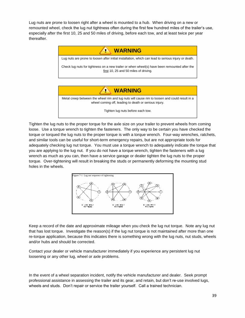
39
Lug nuts are prone to loosen right after a wheel is mounted to a hub. When driving on a new or
remounted wheel, check the lug nut tightness often during the first few hundred miles of the trailer’s use,
especially after the first 10, 25 and 50 miles of driving, before each tow, and at least twice per year
thereafter.
Tighten the lug nuts to the proper torque for the axle size on your trailer to prevent wheels from coming
loose. Use a torque wrench to tighten the fasteners. The only way to be certain you have checked the
torque or torqued the lug nuts to the proper torque is with a torque wrench. Four-way wrenches, ratchets,
and similar tools can be useful for short-term emergency repairs, but are not appropriate tools for
adequately checking lug nut torque. You must use a torque wrench to adequately indicate the torque that
you are applying to the lug nut. If you do not have a torque wrench, tighten the fasteners with a lug
wrench as much as you can, then have a service garage or dealer tighten the lug nuts to the proper
torque. Over-tightening will result in breaking the studs or permanently deforming the mounting stud
holes in the wheels.
Figure 7-1 Lug nut sequence of tightening
Keep a record of the date and approximate mileage when you check the lug nut torque. Note any lug nut
that has lost torque. Investigate the reason(s) if the lug nut torque is not maintained after more than one
re-torque application, because this indicates there is something wrong with the lug nuts, nut studs, wheels
and/or hubs and should be corrected.
Contact your dealer or vehicle manufacturer immediately if you experience any persistent lug nut
loosening or any other lug, wheel or axle problems.
In the event of a wheel separation incident, notify the vehicle manufacturer and dealer. Seek prompt
professional assistance in assessing the trailer and its gear, and retain, but don’t re-use involved lugs,
wheels and studs. Don’t repair or service the trailer yourself. Call a trained technician.
Lug nuts are prone to loosen after initial installation, which can lead to serious injury or death.
Check lug nuts for tightness on a new trailer or when wheel(s) have been remounted after the
first 10, 25 and 50 miles of driving.
WARNING
Metal creep between the wheel rim and lug nuts will cause rim to loosen and could result in a
wheel coming off, leading to death or serious injury.
Tighten lug nuts before each tow.
WARNING
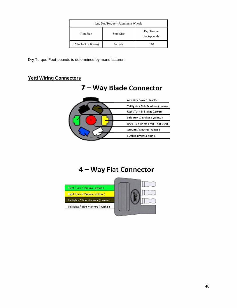
40
Lug Nut Torque – Aluminum Wheels
Rim Size Stud Size Dry Torque
Foot-pounds
15 inch (5 or 6 hole) ½ inch 110
Dry Torque Foot-pounds is determined by manufacturer.
Yetti Wiring Connectors

41
Wireless Remote Error Code CHART TABLE
Error Code PROBABLE CAUSE 1 RECEIVER TO TRANSMITTER COMMUNICATION PROBLEM 2 FAULTY CIRCUIT TO SV1 3 FAULTY CIRCUIT TO SV2 ( Tongue Raise ) 4 FAULTY CIRCUIT TO SV3 ( Tongue Lower ) 5 FAULTY CIRCUIT TO SV4 ( Left/Drivers Raise and Lower ) 6 FAULTY CIRCUIT TO SV5 ( Right/Passengers Raise and Lower ) 7 FAULTY CIRCUIT TO SV6 ( Left/Drivers & Right/Passengers Raise and Lower ) 8 FAULTY CIRCUIT TO SV7 ( Left/Drivers & Right/Passengers Lower ) 9 FAULTY CIRCUIT TO POWER UNIT
10 TX NOT IN NEUTRAL MODE
ERROR CODE NUMBER IS THE NUMBER OF RED LIGHT BLINKS BETWEEN EVERY PAUSE

42
NOTES: