OWNER’S MANUAL - seat.com Leon_EN.pdf · and part replacements. If selling the vehicle, give all...
284
OWNER’S MANUAL Leon
-
Upload
hoangkhanh -
Category
Documents
-
view
214 -
download
0
Transcript of OWNER’S MANUAL - seat.com Leon_EN.pdf · and part replacements. If selling the vehicle, give all...

OWNER’S MANUAL
Leon
5F0012720BC
Ingl
és 5
F001
2720
BC
(11
.14)
(G
T9)
Leon
In
glés
(11
.14)

SEAT S.A. is permanently concerned about continuous development of its types and models. For this reason we ask you to under-stand, that at any given time, changes regarding shape, equipment and technique may take place on the car delivered. For this reason no right at all may derive based on the data, drawings and descriptions in this current handbook.
All texts, illustrations and standards in this handbook are based on the status of information at the time of printing. Except for error or omission, the information included in the current handbook is valid as of the date of closing print.
Re-printing, copying or translating, whether total or partial is not allowed unless SEAT allows it in written form.
SEAT reserves all rights in accordance with the “Copyright” Act.
All rights on changes are reserved.
❀ This paper has been manufactured using bleached non-chlorine cellulose.
© SEAT S.A. - Reprint: 15.11.14
About this manual
This manual contains a description of the equipment supplied with the vehicle at the time this manual was published. Some of the units described herein will not be available until a later date or are only available in cer-tain markets.
Because this is a general manual for the LEON range, some of the equipment and functions that are described in this manual are not in-cluded in all types or variants of the model; they may vary or be modified depending on the technical requirements and on the mar-ket; this is in no way deceptive advertising.
The illustrations are intended as a general guide and may vary from the equipment fitted in your vehicle in some details.
The steering indications (left, right, forward, reverse) appearing in this manual refer to the normal driving movements of the vehicle ex-cept when otherwise indicated.
* The equipment marked with an aster-isk* is fitted as standard only in certain versions, and is only supplied as op-tional extras for some versions, or are only offered in certain countries.
® All registered marks are indicated with ®. Although the copyright symbol does not appear, it is a copyrighted mark.
>> The section is continued on the follow-ing page.
Important warnings on a given page
Detailed contents on a given page
General information on a given page
Emergency information on a given page
WARNING
Texts preceded by this symbol contain infor-mation on safety. They warn you about possi-ble dangers of accident or injury.
CAUTION
Texts with this symbol draw your attention to potential sources of damage to your vehicle.
For the sake of the environment
Texts preceded by this symbol contain rele-vant information concerning environmental protection.
Note
Texts preceded by this symbol contain additio-nal information.
This manual is divided into five large parts, which are:
1. Safety
2. Operation
3. Tips
4. Technical data
5. Alphabetical index
At the end of this manual, there is a detailed alphabetical index that will help you quickly find the information you require.
ForewordThis Instruction Manual and its correspond-ing supplements should be read carefully tofamiliarise yourself with your vehicle.
Besides the regular care and maintenance ofthe vehicle, its correct handling will help pre-serve its value.
For safety reasons, always note the informa-tion concerning accessories, modificationsand part replacements.
If selling the vehicle, give all of the on-boarddocumentation to the new owner, as itshould be kept with the vehicle.
You can access the information in this man-ual using:
● Thematic table of contents that follows themanual’s general chapter structure.
● Visual table of contents that uses graphicsto indicate the pages containing “essential”
information, which is detailed in correspond-ing chapters.
● Alphabetical index with many terms andsynonyms to help you find information.
WARNING
Read and always observe safety informa-tion concerning the passenger's front air-bag ››› page 57, Important informationregarding the front passenger's airbag.


Table of Contents
Table of ContentsThe essentials . . . . . . . . . . . . . . . . . . . . . . . . 5Exterior view . . . . . . . . . . . . . . . . . . . . . . . . . . . . 5Interior view . . . . . . . . . . . . . . . . . . . . . . . . . . . . 7How it works . . . . . . . . . . . . . . . . . . . . . . . . . . . . 9Unlocking and locking . . . . . . . . . . . . . . . . . . . . 9Before driving . . . . . . . . . . . . . . . . . . . . . . . . . . . 11Starting the vehicle . . . . . . . . . . . . . . . . . . . . . . 14Lights and visibility . . . . . . . . . . . . . . . . . . . . . . 15Easy Connect . . . . . . . . . . . . . . . . . . . . . . . . . . . 17Driver information system . . . . . . . . . . . . . . . . . 19Cruise control . . . . . . . . . . . . . . . . . . . . . . . . . . . 21Warning lamps . . . . . . . . . . . . . . . . . . . . . . . . . . 22Gearbox lever . . . . . . . . . . . . . . . . . . . . . . . . . . . 24Air conditioning . . . . . . . . . . . . . . . . . . . . . . . . . 26Level control . . . . . . . . . . . . . . . . . . . . . . . . . . . . 31Action in the event of a puncture . . . . . . . . . . . 33Emergency towing of the vehicle . . . . . . . . . . . 35
Safety . . . . . . . . . . . . . . . . . . . . . . . . . . . . . . . . 37Safe driving . . . . . . . . . . . . . . . . . . . . . . . . . . . . 37Safety first! . . . . . . . . . . . . . . . . . . . . . . . . . . . . . 37Advice about driving . . . . . . . . . . . . . . . . . . . . . 37Sitting position for vehicle occupants . . . . . . . 38Pedal area . . . . . . . . . . . . . . . . . . . . . . . . . . . . . . 42Seat belts . . . . . . . . . . . . . . . . . . . . . . . . . . . . . . 43The reasons why we should wear seat belts . . 43How to properly adjust your seatbelt . . . . . . . . 46Seat belt tensioners . . . . . . . . . . . . . . . . . . . . . . 47Airbag system . . . . . . . . . . . . . . . . . . . . . . . . . . 48Brief introduction . . . . . . . . . . . . . . . . . . . . . . . . 48Airbag overview . . . . . . . . . . . . . . . . . . . . . . . . . 50Deactivating airbags . . . . . . . . . . . . . . . . . . . . . 54Transporting children safety . . . . . . . . . . . . . . . 56Safety for children . . . . . . . . . . . . . . . . . . . . . . . 56Child seats . . . . . . . . . . . . . . . . . . . . . . . . . . . . . 58
Operation . . . . . . . . . . . . . . . . . . . . . . . . . . . . . 65Controls and displays . . . . . . . . . . . . . . . . . . . . 65Overview . . . . . . . . . . . . . . . . . . . . . . . . . . . . . . . 64Instruments and warning/control lamps . . . . . 66Instruments . . . . . . . . . . . . . . . . . . . . . . . . . . . . 66Control lamps . . . . . . . . . . . . . . . . . . . . . . . . . . . 71Driver information system . . . . . . . . . . . . . . . . . 72Information system . . . . . . . . . . . . . . . . . . . . . . 72Driving data . . . . . . . . . . . . . . . . . . . . . . . . . . . . 76Speed warning function . . . . . . . . . . . . . . . . . . . 79Service interval display . . . . . . . . . . . . . . . . . . . 80Introduction to the Easy Connect system* . . . . 81System Settings (CAR)* . . . . . . . . . . . . . . . . . . . 81Opening and closing . . . . . . . . . . . . . . . . . . . . . 82Central locking system . . . . . . . . . . . . . . . . . . . . 82Anti-theft alarm system* . . . . . . . . . . . . . . . . . . 87Rear lid (luggage compartment) . . . . . . . . . . . . 89Electric windows . . . . . . . . . . . . . . . . . . . . . . . . . 90Panoramic sliding sunroof* . . . . . . . . . . . . . . . . 92Lights and visibility . . . . . . . . . . . . . . . . . . . . . . 94Lights . . . . . . . . . . . . . . . . . . . . . . . . . . . . . . . . . 94Visibility . . . . . . . . . . . . . . . . . . . . . . . . . . . . . . . 101Windscreen wiper and window wiper systems . 102Rear vision mirror . . . . . . . . . . . . . . . . . . . . . . . . 104Seats and head restraints . . . . . . . . . . . . . . . . . 106Adjusting the seats and headrests . . . . . . . . . . 106Seat functions . . . . . . . . . . . . . . . . . . . . . . . . . . 107Transport and practical equipment . . . . . . . . . 111Storage compartments . . . . . . . . . . . . . . . . . . . 111Storing objects . . . . . . . . . . . . . . . . . . . . . . . . . . 114Roof carrier . . . . . . . . . . . . . . . . . . . . . . . . . . . . . 122Air conditioning . . . . . . . . . . . . . . . . . . . . . . . . . 124Heating, ventilation and cooling . . . . . . . . . . . . 124Driving . . . . . . . . . . . . . . . . . . . . . . . . . . . . . . . . 129Ignition lock . . . . . . . . . . . . . . . . . . . . . . . . . . . . 129Braking and parking . . . . . . . . . . . . . . . . . . . . . 131Manual gearbox . . . . . . . . . . . . . . . . . . . . . . . . . 132
Automatic gearbox/DSG automatic gearbox* . 132Run-in and economical driving . . . . . . . . . . . . . 140Driver assistance systems . . . . . . . . . . . . . . . . . 143Braking and stability systems . . . . . . . . . . . . . . 143Start-Stop system* . . . . . . . . . . . . . . . . . . . . . . . 148Cruise control system (CCS)* . . . . . . . . . . . . . . . 150Adaptive Cruise Control ACC* . . . . . . . . . . . . . . 151Monitoring system Front Assist* . . . . . . . . . . . . 161Lane Assist system* . . . . . . . . . . . . . . . . . . . . . . 166SEAT driving modes (SEAT Drive Profile)* . . . . . 169Tiredness detection (break recommendation)* 172Parking aid . . . . . . . . . . . . . . . . . . . . . . . . . . . . . 173Towing bracket device . . . . . . . . . . . . . . . . . . . . 177Trailer towing . . . . . . . . . . . . . . . . . . . . . . . . . . . 177
Advice . . . . . . . . . . . . . . . . . . . . . . . . . . . . . . . . 182Care and maintenance . . . . . . . . . . . . . . . . . . . . 182Accessories and modifications to the vehicle . 182Care and cleaning . . . . . . . . . . . . . . . . . . . . . . . 183Vehicle exterior care . . . . . . . . . . . . . . . . . . . . . . 183Care of the vehicle interior . . . . . . . . . . . . . . . . . 187Intelligent technology . . . . . . . . . . . . . . . . . . . . 190Electro-mechanical steering . . . . . . . . . . . . . . . 190Progressive steering . . . . . . . . . . . . . . . . . . . . . 190Four-wheel drive . . . . . . . . . . . . . . . . . . . . . . . . . 191Power Management . . . . . . . . . . . . . . . . . . . . . . 191Checking and refilling levels . . . . . . . . . . . . . . . 193Refuelling . . . . . . . . . . . . . . . . . . . . . . . . . . . . . . 193Fuel . . . . . . . . . . . . . . . . . . . . . . . . . . . . . . . . . . . 195Bonnet . . . . . . . . . . . . . . . . . . . . . . . . . . . . . . . . 198Engine oil . . . . . . . . . . . . . . . . . . . . . . . . . . . . . . 200Cooling system . . . . . . . . . . . . . . . . . . . . . . . . . . 203Brake fluid . . . . . . . . . . . . . . . . . . . . . . . . . . . . . 204Windscreen washer reservoir . . . . . . . . . . . . . . 204Battery . . . . . . . . . . . . . . . . . . . . . . . . . . . . . . . . . 205Wheels . . . . . . . . . . . . . . . . . . . . . . . . . . . . . . . . 208Wheels and tyres . . . . . . . . . . . . . . . . . . . . . . . . 208Tyre monitoring systems . . . . . . . . . . . . . . . . . . 212
3
Table of Contents
Compact temporary spare wheel . . . . . . . . . . . . 214Winter service . . . . . . . . . . . . . . . . . . . . . . . . . . . 215Emergencies . . . . . . . . . . . . . . . . . . . . . . . . . . . . 217Changing a wheel . . . . . . . . . . . . . . . . . . . . . . . 217Tyre repair . . . . . . . . . . . . . . . . . . . . . . . . . . . . . . 220Jump starting . . . . . . . . . . . . . . . . . . . . . . . . . . . 223Towing and tow-starting the vehicle . . . . . . . . . 224Emergency locking and unlocking . . . . . . . . . . 227Fuses and bulbs . . . . . . . . . . . . . . . . . . . . . . . . . 231Fuses . . . . . . . . . . . . . . . . . . . . . . . . . . . . . . . . . . 231Bulbs . . . . . . . . . . . . . . . . . . . . . . . . . . . . . . . . . . 233Changing bulbs in headlight unit . . . . . . . . . . . 235Changing bulb for front fog light* . . . . . . . . . . . 236Changing tail light bulbs (on side panel) . . . . . 237Changing tail light bulbs (on rear lid) . . . . . . . . 239
Technical specifications . . . . . . . . . . . . . . . 241Technical specifications . . . . . . . . . . . . . . . . . . 241Important . . . . . . . . . . . . . . . . . . . . . . . . . . . . . . 241Vehicle identification data . . . . . . . . . . . . . . . . . 241Information on fuel consumption . . . . . . . . . . . 242Towing a trailer . . . . . . . . . . . . . . . . . . . . . . . . . . 243Wheels . . . . . . . . . . . . . . . . . . . . . . . . . . . . . . . . 243Engine specifications . . . . . . . . . . . . . . . . . . . . . 245Dimensions . . . . . . . . . . . . . . . . . . . . . . . . . . . . . 267Filling capacities . . . . . . . . . . . . . . . . . . . . . . . . 268
Index . . . . . . . . . . . . . . . . . . . . . . . . . . . . . . . . . 269
4

The essentials
Exterior view
Fig. 1 »
5
Tech
nical
spec
ificati
ons
Adv
ice
Ope
rati
onS
afet
yTh
e es
sent
ials

The essentials
Fig. 2
6

The essentials
Interior view
Fig. 3 Left hand drive »
7
Tech
nical
spec
ificati
ons
Adv
ice
Ope
rati
onS
afet
yTh
e es
sent
ials
The essentials
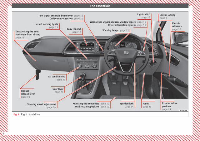
Fig. 4 Right hand drive
8

The essentials
How it worksUnlocking and locking
Doors
Fig. 5
Fig. 6 See Fig. 3 for positioning
Locking and unlocking the vehicle using thekey
● Locking: press the ››› Fig. 5 button.
● Locking the vehicle without activating theanti-theft system: Press the ››› Fig. 5 buttonfor a second time for the next 2 seconds.
● Unlocking: press the ››› Fig. 5 button.
● Unlocking the rear lid: Hold down the ››› Fig. 5 button for at least 1 second.
Locking and unlocking with the centrallocking switch
● Locking: press the ››› Fig. 6 button. Noneof the doors can be opened from the outside.The doors can be opened from the inside bypulling the inside door handle.
● Unlocking: press the ››› Fig. 6 button.
››› in Description on page 82
››› page 82
››› page 227
Rear lid
Fig. 7
● Opening the rear lid: Pull on the releaselever and lift it up ››› Fig. 7. The rear lid opensautomatically.
● Closing the rear lid: Hold it by one of thehandles on the interior lining and close it bypushing gently.
››› in Rear lid on page 90
››› page 89
››› page 229
9
Tech
nical
spec
ificati
ons
Adv
ice
Ope
rati
onS
afet
yTh
e es
sent
ials

The essentials
Bonnet
Fig. 8 See Fig. 3 for positioning
Fig. 9
● Opening the bonnet: Pull the lever underthe dashboard ››› Fig. 8 1 .
● Lift up the bonnet. Press the release catchunder the bonnet upwards ››› Fig. 9 2 . Thearrester hook under the bonnet is released.
● The bonnet can be opened. Release thebonnet stay and secure it in the fixture de-signed for this in the bonnet.
››› in Work in the engine compartmenton page 198
››› page 198
Electric windows*
Fig. 10 See Fig. 3 for positioning
● Opening the window: Press the button.
● Closing the window: Pull the button.
Buttons on the driver door
Window on the front left door1
Window on the front right door
Window on the rear left door (only 5-doorvehicles)
Window on the right rear door (only 5-door vehicles)
Safety switch for deactivating the electricwindow buttons on the rear doors (only 5-door vehicles)
››› in Opening and closing of the elec-tric windows* on page 91
››› page 90
2
3
4
5
10

The essentials
Sunroof*
Fig. 11
Fig. 12
● Opening: Turn the switch to position››› Fig. 11 3 .
● Convenience position: Turn the switch toposition ››› Fig. 11 2 .
● Closing: Turn the switch to position››› Fig. 11 1 .
● To tilt open: Push the switch to position››› Fig. 12 4 . For an intermediate position,hold down the switch until you reach the de-sired position.
● Lowering: Pull the switch to position››› Fig. 12 5 . For an intermediate position,hold down the switch until you reach the de-sired position.
››› in Opening or closing the panoramicsliding sunroof on page 92
››› page 92
Before driving
Deactivating the front passenger frontairbag
Fig. 13
To deactivate the front passenger frontairbag:
● Open the glove compartment on the frontpassenger side.
● Insert the key into the slot provided in thedeactivation switch.
● Approximately ¾ of the length of the keyremains inserted (the maximum).
● Turn the key, changing its position to .Do not force it. If you have difficulty, ensurethat you have inserted the key as far as it willgo.
● Finally, check the control lamp on the in-strument panel where it shows the following should appear .
››› in Disabling the front airbag onpage 55
››› page 54
11
Tech
nical
spec
ificati
ons
Adv
ice
Ope
rati
onS
afet
yTh
e es
sent
ials

The essentials
Manually adjusting the front seats
Fig. 14
Forward/back: pull the lever and movethe seat forwards or backwards.
Raising/lowering: pull/push the lever.
Tilting the backrest: turn the hand wheel.
Lumbar support: Press the button in thecorresponding position.
Folding down the backrest (only 3-doorvehicles): pull the lever and push thebackrest forward.
››› in Manual adjustment of seats onpage 106
1
2
3
4
5
Electric adjustment of the driver'sseat*
Fig. 15
Adjusting the lumbar support: press thebutton according to the desired position.
Seat up/down: Press the buttonup/down. To adjust the front of the seatcushion, press the front of the buttonup/down. To adjust the rear of the seatcushion, press the rear of the buttonup/down.
Seat forwards/backwards: press the but-ton forwards/backwards.
Backrest further upright/further reclined:press the button forwards/backwards.
››› in Electric driver seat adjustment*on page 106
A
B
C
Adjusting the head restraints
Fig. 16
Grab the sides of the head restraints withboth hands and push upwards to the desiredposition. To lower it, repeat the same action,pressing the 1 button on the side.
››› in Correct adjustment of front headrestraints on page 41
››› page 41 ››› page 107
12
The essentials
Adjusting the seat belt
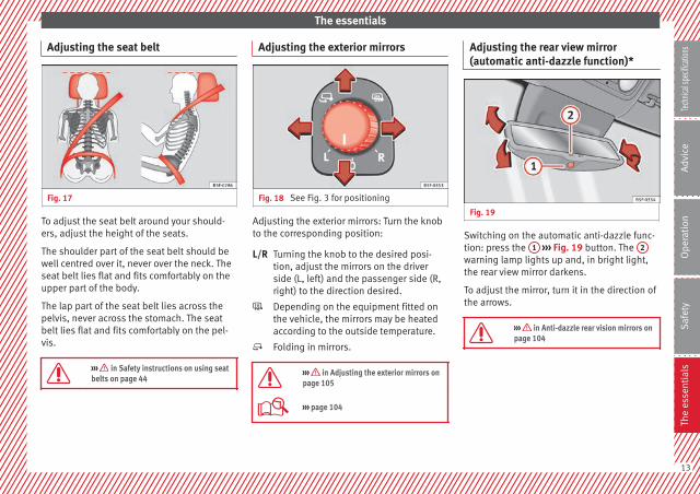
Fig. 17
To adjust the seat belt around your should-ers, adjust the height of the seats.
The shoulder part of the seat belt should bewell centred over it, never over the neck. Theseat belt lies flat and fits comfortably on theupper part of the body.
The lap part of the seat belt lies across thepelvis, never across the stomach. The seatbelt lies flat and fits comfortably on the pel-vis.
››› in Safety instructions on using seatbelts on page 44
Adjusting the exterior mirrors
Fig. 18 See Fig. 3 for positioning
Adjusting the exterior mirrors: Turn the knobto the corresponding position:
Turning the knob to the desired posi-tion, adjust the mirrors on the driverside (L, left) and the passenger side (R,right) to the direction desired.
Depending on the equipment fitted onthe vehicle, the mirrors may be heatedaccording to the outside temperature.
Folding in mirrors.
››› in Adjusting the exterior mirrors onpage 105
››› page 104
L/R
Adjusting the rear view mirror(automatic anti-dazzle function)*
Fig. 19
Switching on the automatic anti-dazzle func-tion: press the 1 ››› Fig. 19 button. The 2
warning lamp lights up and, in bright light,the rear view mirror darkens.
To adjust the mirror, turn it in the direction ofthe arrows.
››› in Anti-dazzle rear vision mirrors onpage 104
13
Tech
nical
spec
ificati
ons
Adv
ice
Ope
rati
onS
afet
yTh
e es
sent
ials

The essentials
Adjusting the steering wheel
Fig. 20
Adjusting the position of the steering wheel:Pull the ››› Fig. 20 1 lever down, move thesteering wheel to the desired position and liftthe lever back up until it locks.
››› in Adjusting the steering wheel po-sition on page 39
Starting the vehicle
Ignition lock
Fig. 21 See Fig. 3 for positioning
Switch ignition on: Place the key in the igni-tion and start the engine.
Locking and unlocking the steering wheel
● Engaging the steering wheel lock: Removethe key from the ignition and turn the wheeluntil it locks. In vehicles with an automaticgearbox, the gear lever must be in the P posi-tion in order to remove the key. If necessary,press the locking key on the selector leverand release it again.
● Unlocking the steering wheel: Put the keyinto the ignition and turn it at the same timeas the steering wheel in the direction indica-ted by the arrow. If it is not possible to turnthe steering wheel, it may be because it islocked.
Turning on/switching off the ignition, glowplugs reheating
● Switch ignition on: Turn the key to the 2
position.
● Switch ignition off. Turn the key to the 1
position.
● Diesel vehicles : The glow plugs reheatwhen the ignition is switched on
Starting the engine
● Manual gearbox: press the clutch pedal allthe way down and move the gearbox lever in-to neutral.
● Automatic gearbox: Press the brake pedaland move the selector lever to the P positionor into N.
● Turn the key to the 3 position. The key au-tomatically returns to the 2 position. Do notpress the accelerator.
Start-Stop System*
When you stop and release the clutch pedal,the Start-Stop system* turns off the engine.The ignition remains switched on.
››› in Switching on the ignition andstarting the engine with the key onpage 130
››› page 129
14
The essentials
Lights and visibility
Light switch
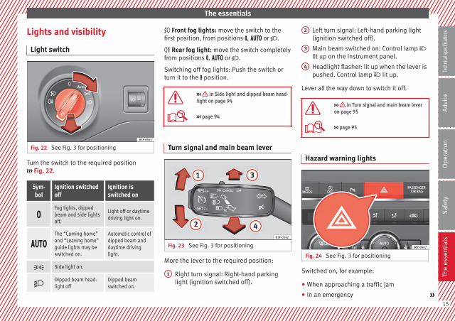
Fig. 22 See Fig. 3 for positioning
Turn the switch to the required position››› Fig. 22.
Sym-bol
Ignition switchedoff
Ignition isswitched on
Fog lights, dippedbeam and side lightsoff.
Light off or daytimedriving light on.
The “Coming home”and “Leaving home”guide lights may beswitched on.
Automatic control ofdipped beam anddaytime drivinglight.
Side light on.
Dipped beam head-light off
Dipped beamswitched on.
Front fog lights: move the switch to thefirst position, from positions , or .
Rear fog light: move the switch completelyfrom positions , or .
Switching off fog lights: Push the switch orturn it to the position.
››› in Side light and dipped beam head-light on page 94
››› page 94
Turn signal and main beam lever
Fig. 23 See Fig. 3 for positioning
More the lever to the required position:
Right turn signal: Right-hand parkinglight (ignition switched off).
1
Left turn signal: Left-hand parking light(ignition switched off).
Main beam switched on: Control lamp lit up on the instrument panel.
Headlight flasher: lit up when the lever ispushed. Control lamp lit up.
Lever all the way down to switch it off.
››› in Turn signal and main beam leveron page 95
››› page 95
Hazard warning lights
Fig. 24 See Fig. 3 for positioning
Switched on, for example:
● When approaching a traffic jam
● In an emergency »
2
3
4
15
Tech
nical
spec
ificati
ons
Adv
ice
Ope
rati
onS
afet
yTh
e es
sent
ials

The essentials
● The vehicle has broken down
● When towing or being towed
››› in Hazard warning lights onpage 99
››› page 99
Interior lights
Fig. 25
Knob Function
Switches interior lights off.
Switches interior lights on.
Knob Function
Switches door contact control on (central po-sition).The interior lights come on automaticallywhen the vehicle is unlocked, a door isopened or the key is removed from the igni-tion.The lights go off a few seconds after all thedoors are closed, the vehicle is locked or theignition is switched on.
Turning the reading light on and off
Ambient light: in the door panel, it changescolour (white or red) depending on the driv-ing mode.
››› page 101
Windscreen wipers and window wiperblade
Fig. 26
More the lever to the required position:
0 Windscreen wiper off.
1
Windscreen wipers interval wipe.Using the control ››› Fig. 26 A adjust theinterval (vehicles without rain sensor), orthe sensitivity of the rain sensor.
2 Slow wipe.
3 Continuous wipe.
4 Short wipe. Brief press, short clean. Holdthe lever down for more time to increasethe wipe frequency.
5
Automatic wipe. The windscreen washerfunction is activated by pushing the leverforwards, and simultaneously the wind-screen wipers start.
16

The essentials
More the lever to the required position:
6 Interval wipe for rear window. The wiperwill wipe the window approximately everysix seconds.
More the lever to the required position:
7 The rear window wash function is activa-ted by pressing the lever, and the rearwiper starts simultaneously.
››› page 102
››› page 230
Easy Connect
CAR menu Setup
Fig. 27 See Fig. 3 for positioning Fig. 28 See Fig. 3 for positioning
● Switch the ignition on.
● Switch on the Easy Connect system.
● Press the Easy Connect button ››› Fig. 27.
● Press the function button Setup to open themenu Vehicle settings ››› Fig. 28.
● To select a function in the menu, keep thedesired button pressed down. »
17
Tech
nical
spec
ificati
ons
Adv
ice
Ope
rati
onS
afet
yTh
e es
sent
ials
The essentials
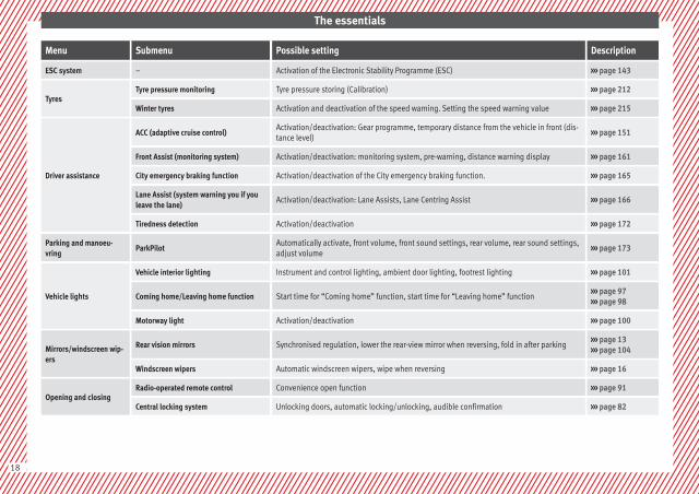
Menu Submenu Possible setting Description
ESC system – Activation of the Electronic Stability Programme (ESC) ››› page 143
TyresTyre pressure monitoring Tyre pressure storing (Calibration) ››› page 212
Winter tyres Activation and deactivation of the speed warning. Setting the speed warning value ››› page 215
Driver assistance
ACC (adaptive cruise control)Activation/deactivation: Gear programme, temporary distance from the vehicle in front (dis-tance level)
››› page 151
Front Assist (monitoring system) Activation/deactivation: monitoring system, pre-warning, distance warning display ››› page 161
City emergency braking function Activation/deactivation of the City emergency braking function. ››› page 165
Lane Assist (system warning you if youleave the lane)
Activation/deactivation: Lane Assists, Lane Centring Assist ››› page 166
Tiredness detection Activation/deactivation ››› page 172
Parking and manoeu-vring
ParkPilotAutomatically activate, front volume, front sound settings, rear volume, rear sound settings,adjust volume
››› page 173
Vehicle lights
Vehicle interior lighting Instrument and control lighting, ambient door lighting, footrest lighting ››› page 101
Coming home/Leaving home function Start time for “Coming home” function, start time for “Leaving home” function››› page 97››› page 98
Motorway light Activation/deactivation ››› page 100
Mirrors/windscreen wip-ers
Rear vision mirrors Synchronised regulation, lower the rear-view mirror when reversing, fold in after parking››› page 13››› page 104
Windscreen wipers Automatic windscreen wipers, wipe when reversing ››› page 16
Opening and closingRadio-operated remote control Convenience open function ››› page 91
Central locking system Unlocking doors, automatic locking/unlocking, audible confirmation ››› page 82
18
The essentials
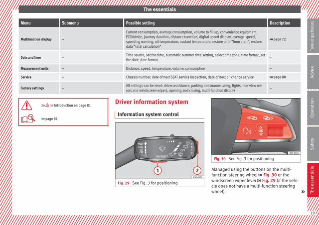
Menu Submenu Possible setting Description
Multifunction display –
Current consumption, average consumption, volume to fill up, convenience equipment,ECOAdvice, journey duration, distance travelled, digital speed display, average speed,speeding warning, oil temperature, coolant temperature, restore data “from start”, restoredata “total calculation”
››› page 72
Date and time –Time source, set the time, automatic summer time setting, select time zone, time format, setthe date, date format
–
Measurement units – Distance, speed, temperature, volume, consumption –
Service – Chassis number, date of next SEAT service inspection, date of next oil change service ››› page 80
Factory settings –All settings can be reset: driver assistance, parking and manoeuvring, lights, rear view mir-rors and windscreen wipers, opening and closing, multi-function display
–
››› in Introduction on page 81
››› page 81
Driver information system
Information system control
Fig. 29 See Fig. 3 for positioning
Fig. 30 See Fig. 3 for positioning
Managed using the buttons on the multi-function steering wheel ››› Fig. 30 or thewindscreen wiper lever ››› Fig. 29 (if the vehi-cle does not have a multi-function steeringwheel). »
19
Tech
nical
spec
ificati
ons
Adv
ice
Ope
rati
onS
afet
yTh
e es
sent
ials
The essentials
Windscreen wiper lever
Press to select and confirm ››› Fig. 29
Press up or down to view the submenu››› Fig. 29
Multifunction steering wheel
● : press to select and confirm ››› Fig. 30
● / : press to view the submenu››› Fig. 30
››› in Introduction on page 72
››› page 72
1
2
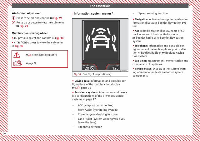
Information system menus*
Fig. 31 See Fig. 3 for positioning
● Driving data: Information and possible con-figurations of the multifunction display››› page 76
● Assistance systems: information and possi-ble configurations of the driver assistancesystems ››› page 17
ACC (adaptive cruise control)
Front Assist (monitoring system)
City emergency braking function
Lane Assist (system warning you if youleave the lane)
Tiredness detection
–
–
–
–
–
Speed warning function
● Navigation: Activated navigation system in-formation display ››› Booklet Navigation sys-tem
● Audio: Radio station display, name of CDtrack or name of track in Media mode››› Booklet Radio or ››› Booklet Navigationsystem
● Telephone: Information and possible con-figurations of the mobile phone preinstalla-tion ››› Booklet Radio or ››› Booklet Naviga-tion system
● Lap timer: measurement, memorisation andcomparison of lap times
● Vehicle status: Display of the current warn-ing or information texts and other systemcomponents
–
20
The essentials
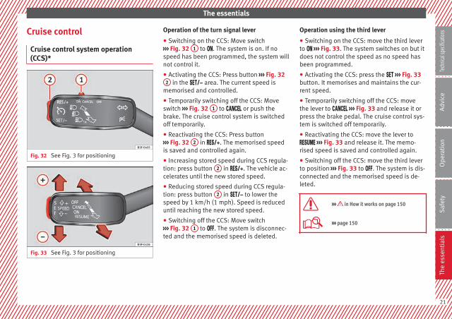
Cruise control
Cruise control system operation(CCS)*
Fig. 32 See Fig. 3 for positioning
Fig. 33 See Fig. 3 for positioning
Operation of the turn signal lever
● Switching on the CCS: Move switch››› Fig. 32 1 to . The system is on. If nospeed has been programmed, the system willnot control it.
● Activating the CCS: Press button ››› Fig. 322 in the area. The current speed is
memorised and controlled.
● Temporarily switching off the CCS: Moveswitch ››› Fig. 32 1 to or push thebrake. The cruise control system is switchedoff temporarily.
● Reactivating the CCS: Press button››› Fig. 32 2 in . The memorised speedis saved and controlled again.
● Increasing stored speed during CCS regula-tion: press button 2 in . The vehicle ac-celerates until the new stored speed.
● Reducing stored speed during CCS regula-tion: press button 2 in to lower thespeed by 1 km/h (1 mph). Speed is reduceduntil reaching the new stored speed.
● Switching off the CCS: Move switch››› Fig. 32 1 to . The system is disconnec-ted and the memorised speed is deleted.
Operation using the third lever
● Switching on the CCS: move the third leverto ››› Fig. 33. The system switches on but itdoes not control the speed as no speed hasbeen programmed.
● Activating the CCS: press the ››› Fig. 33button. It memorises and maintains the cur-rent speed.
● Temporarily switching off the CCS: movethe lever to ››› Fig. 33 and release it orpress the brake pedal. The cruise control sys-tem is switched off temporarily.
● Reactivating the CCS: move the lever to ››› Fig. 33 and release it. The memo-rised speed is saved and controlled again.
● Switching off the CCS: move the third leverto position ››› Fig. 33 to . The system is dis-connected and the memorised speed is de-leted.
››› in How it works on page 150
››› page 150
21
Tech
nical
spec
ificati
ons
Adv
ice
Ope
rati
onS
afet
yTh
e es
sent
ials

The essentials
Warning lamps
On the instrument panel
Fig. 34 See Fig. 3 for positioning
Red warning lamps
Central warning lamp: additionalinformation on the instrument pan-el display
–
Parking brake on. ››› page 131››› page 146
Do not continue driving!The brake fluid level is too low orthere is a fault in the brake system.
Lit up or flashing: Do not continue driving!Fault in the steering.
››› page 190
Driver or passenger has not fas-tened seat belt.
››› page 43
Use the foot brake!
Yellow warning lamps
Central warning lamp: additionalinformation on the instrument pan-el display
–
22
The essentials
Front brake pads worn.
››› page 143
it lights up: Fault in the ESC, or dis-connection caused by the system.
flashes: ESC or ASR activated.
ASR manually deactivated.
ABS faulty or does not work.
Rear fog light switched on.››› page 94
lights up or flashes: fault in theemission control system.
–
it lights up: pre-ignition of dieselengine. ››› page
71flashes: fault in the diesel enginemanagement.
fault in the petrol engine manage-ment.
››› page 71
lights up or flashes: fault in thesteering system.
››› page 190
Tyre pressure too low, or fault inthe tyre pressure monitoring sys-tem.
››› page 212
Fuel tank almost empty.››› page 66
Fault in airbag system and seatbelt tensioners.
››› page 48
Lane Assist is switched on, but notactive.
››› page 166
Other warning lamps
Left or right turn signal.
››› page 94
Hazard warning lights on.››› page 99
Trailer turn signals››› page 177
it lights up: Press the foot brake!flashes: the selector lever lockingbutton has not engaged.
››› page 132
it lights up: cruise control activatedor speed limiter switched on andactive. ››› page
150flashes: the speed set by thespeed limiter has been exceeded.
Lane Assist is switched on and ac-tive.
››› page 166
Main beam on or flasher on.››› page 94
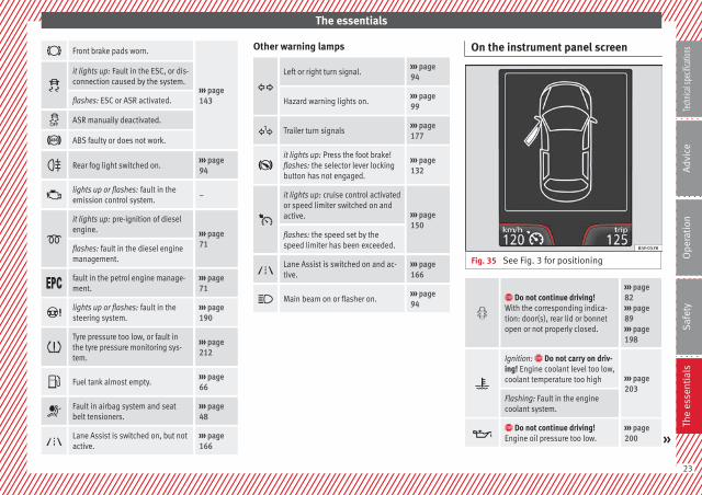
On the instrument panel screen
Fig. 35 See Fig. 3 for positioning
Do not continue driving!With the corresponding indica-tion: door(s), rear lid or bonnetopen or not properly closed.
››› page 82››› page 89››› page 198
Ignition: Do not carry on driv-ing! Engine coolant level too low,coolant temperature too high ››› page
203Flashing: Fault in the enginecoolant system.
Do not continue driving!Engine oil pressure too low.
››› page 200 »
23
Tech
nical
spec
ificati
ons
Adv
ice
Ope
rati
onS
afet
yTh
e es
sent
ials

The essentials
Fault in the battery.››› page 205
Driving light totally or partiallyfaulty.
››› page 233
Fault in the cornering light sys-tem.
››› page 94
Diesel particulate filter blocked››› page 141
Level of windscreen washer fluidtoo low.
››› page 102
Flashing: Fault in the oil level de-tection. Control manually. ››› page
200Ignition: Insufficient engine oil.
Fault in the gearbox.››› page 139
Light Assist on.››› page 96
Immobiliser active.
Service interval display››› page 80
Mobile telephone is connectedvia Bluetooth to the original tele-phone device.
››› Book-let Radioor››› Book-let Navi-gationsystem
Mobile telephone battery chargemeter. Available only for devicespre-installed in factory.
Freezing warning. The outsidetemperature is lower than +4°C(+39°F).
››› page 74
Start-Stop system activated. ››› page 148
Start-Stop system unavailable.
Low consumption driving status››› page 74
On the instrument panel
Fig. 36 See Fig. 3 for positioning
Front passenger front airbag isdisabled ( ).
››› page 48
The front passenger front airbagis activated ( ).
››› page 48
››› in Control and warning lamps onpage 71
››› page 71
Gearbox lever
Manual gearbox
Fig. 37
The position of the gears is indicated on thegearbox lever ››› Fig. 37.
● Press the clutch pedal and keep your footright down.
● Move the gearbox lever to the required po-sition.
● Release the clutch.
24
The essentials
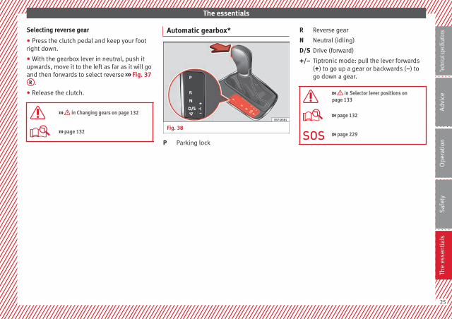
Selecting reverse gear
● Press the clutch pedal and keep your footright down.
● With the gearbox lever in neutral, push itupwards, move it to the left as far as it will goand then forwards to select reverse ››› Fig. 37R .
● Release the clutch.
››› in Changing gears on page 132
››› page 132
Automatic gearbox*
Fig. 38
Parking lockP
Reverse gear
Neutral (idling)
Drive (forward)
Tiptronic mode: pull the lever forwards(+) to go up a gear or backwards (–) togo down a gear.
››› in Selector lever positions onpage 133
››› page 132
››› page 229
R
N
D/S
+/–
25
Tech
nical
spec
ificati
ons
Adv
ice
Ope
rati
onS
afet
yTh
e es
sent
ials

The essentials
Air conditioning
How does Climatronic* work?
Fig. 39 See Fig. 3 for positioning
To switch a specific function on, press the ap-propriate button. Press the button again toswitch off the function.
The LED on each control lights up to indicatethat the respective function of a control hasbeen switched on.
1
TemperatureThe left and right sides can be adjusted separately: Turn the control to adjust the temperature
2
FanThe power of the fan is automatically adjusted. The fan is also adjusted manually by turning the control.
3
Air distributionThe airflow adjusts automatically for comfort. You can also switch it on manually using the buttons 3 .
4 Indications on the temperature display screen selected for the right and left sides.
26
The essentials
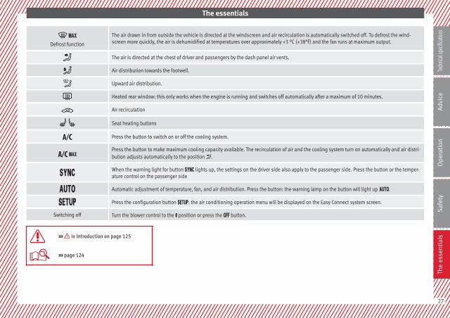
Defrost function
The air drawn in from outside the vehicle is directed at the windscreen and air recirculation is automatically switched off. To defrost the wind-screen more quickly, the air is dehumidified at temperatures over approximately +3 °C (+38°F) and the fan runs at maximum output.
The air is directed at the chest of driver and passengers by the dash panel air vents.
Air distribution towards the footwell.
Upward air distribution.
Heated rear window: this only works when the engine is running and switches off automatically after a maximum of 10 minutes.
Air recirculation
Seat heating buttons
Press the button to switch on or off the cooling system.
Press the button to make maximum cooling capacity available. The recirculation of air and the cooling system turn on automatically and air distri-bution adjusts automatically to the position .
When the warning light for button lights up, the settings on the driver side also apply to the passenger side. Press the button or the temper-ature control on the passenger side
Automatic adjustment of temperature, fan, and air distribution. Press the button: the warning lamp on the button will light up .
Press the configuration button : the air conditioning operation menu will be displayed on the Easy Connect system screen.
Switching off Turn the blower control to the position or press the button.
››› in Introduction on page 125
››› page 124
27
Tech
nical
spec
ificati
ons
Adv
ice
Ope
rati
onS
afet
yTh
e es
sent
ials
The essentials
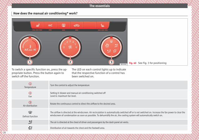
How does the manual air conditioning* work?
Fig. 40 See Fig. 3 for positioning
To switch a specific function on, press the ap-propriate button. Press the button again toswitch off the function.
The LED on each control lights up to indicatethat the respective function of a control hasbeen switched on.
1
TemperatureTurn the control to adjust the temperature
2
FanSetting 0: blower and manual air conditioning switched offLevel 6: maximum fan level.
3
Air distributionRotate the continuous control to direct the airflow to the desired area.
Defrost function
The airflow is directed at the windscreen. Air recirculation is automatically switched off or is not switched on. Increase the fan power to clear thewindscreen of condensation as soon as possible. To dehumidify the air, the cooling system will automatically switch on.
The air is directed at the chest of driver and passengers by the dash panel air vents.
Distribution of air towards the chest and the footwell area.
28

The essentials
Air distribution towards the footwell.
Air distribution towards the windscreen and the footwell.
Heated rear window: this only works when the engine is running and switches off automatically after a maximum of 10 minutes.
Air recirculation
Seat heating buttons
Maximum cooling power. The recirculation of air and the cooling system turn on automatically and air distribution adjusts automatically to theposition
››› in Introduction on page 125
››› page 124
How does the heating and the fresh air system work?
Fig. 41 See Fig. 3 for positioning »29
Tech
nical
spec
ificati
ons
Adv
ice
Ope
rati
onS
afet
yTh
e es
sent
ials

The essentials
To switch a specific function on, press the ap-propriate button. Press the button again toswitch off the function.
The LED on each control lights up to indicatethat the respective function of a control hasbeen switched on.
1
TemperatureTurn the control to adjust the temperature. The temperature cannot be lower than that of the exterior air temperature, as this system cannot coolor dehumidify the air
2
FanSetting 0: blower, heating and fresh air systems switched offLevel 6: maximum fan level
3
Air distributionRotate the continuous control to direct the airflow to the desired area.
Defrost function
The airflow is directed at the windscreen.
The air is directed at the chest of driver and passengers by the dash panel air vents.
Distribution of air towards the chest and the footwell area.
Air distribution towards the footwell.
Air distribution towards the windscreen and the footwell.
Heated rear window: this only works when the engine is running and switches off automatically after a maximum of 10 minutes
Air recirculation ››› page 128
Seat heating buttons
››› in Introduction on page 125
››› page 124
30
The essentials
Level control
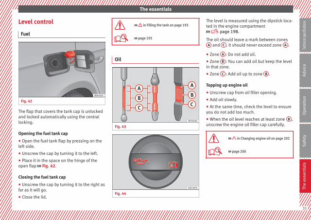
Fuel
Fig. 42
The flap that covers the tank cap is unlockedand locked automatically using the centrallocking.
Opening the fuel tank cap
● Open the fuel tank flap by pressing on theleft side.
● Unscrew the cap by turning it to the left.
● Place it in the space on the hinge of theopen flap ››› Fig. 42.
Closing the fuel tank cap
● Unscrew the cap by turning it to the right asfar as it will go.
● Close the lid.
››› in Filling the tank on page 193
››› page 193
Oil
Fig. 43
Fig. 44
The level is measured using the dipstick loca-ted in the engine compartment››› page 198.
The oil should leave a mark between zonesA and C . It should never exceed zone A .
● Zone A : Do not add oil.
● Zone B : You can add oil but keep the levelin that zone.
● Zone C : Add oil up to zone B .
Topping up engine oil
● Unscrew cap from oil filler opening.
● Add oil slowly.
● At the same time, check the level to ensureyou do not add too much.
● When the oil level reaches at least zone B ,unscrew the engine oil filler cap carefully.
››› in Changing engine oil on page 202
››› page 200
31
Tech
nical
spec
ificati
ons
Adv
ice
Ope
rati
onS
afet
yTh
e es
sent
ials
The essentials
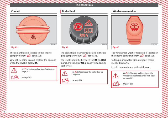
Coolant
Fig. 45
The coolant tank is located in the enginecompartment ››› page 198.
When the engine is cold, replace the coolantwhen the level is below .
››› in Engine coolant specifications onpage 203
››› page 203
Brake fluid
Fig. 46
The brake fluid reservoir is located in the en-gine compartment ››› page 198.
The level should be between the and marks. If it is below , please visit a Techni-cal Service.
››› in Topping up the brake fluid onpage 204
››› page 204
Windscreen washer
Fig. 47
The windscreen washer reservoir is located inthe engine compartment ››› page 198.
To top up, mix water with a product recom-mended by SEAT.
In cold temperatures, add anti-freeze.
››› in Checking and topping up thewindscreen washer reservoir with wateron page 205
››› page 204
32

The essentials
Fuses
Fig. 48
Fig. 49
Underneath the instrument panel
The fuse box is located behind the storagecompartment ››› Fig. 48.
In the engine compartment
Press the locking tabs to release the fuse boxcover ››› Fig. 49.
››› in Introduction on page 231
››› page 231
Battery
The battery is located in the engine compart-ment ››› page 198. It does not requiremaintenance. It is checked as part of the In-spection Service.
››› in Important safety warnings forhandling a vehicle battery on page 206
››› page 205
Action in the event of apuncture
With anti-puncture kit
Fig. 50
The anti-puncture kit is located under thefloor panel in the luggage compartment.
Sealing the tyre
● Unscrew the tyre valve cap and insert. Usethe ››› Fig. 50 1 tool to remove the insert.Place it on a clean surface.
● Shake the tyre sealant bottle vigorously››› Fig. 50 10 .
● Screw the inflator tube ››› Fig. 50 3 intothe sealant bottle. The bottle's seal will breakautomatically. »
33
Tech
nical
spec
ificati
ons
Adv
ice
Ope
rati
onS
afet
yTh
e es
sent
ials

The essentials
● Remove the lid from the filling tube››› Fig. 50 3 and screw the open end of thetube into the tyre valve.
● With the tyre sealant bottle upside down,fill the tyre with the contents of the sealantbottle.
● Remove the bottle from the valve.
● Place the insert back into the tyre valve us-ing the tool ››› Fig. 50 1 .
Inflating the tyre
● Screw the compressor tyre inflator tube››› Fig. 50 5 into the tyre valve.
● Check that the air bleed screw is closed››› Fig. 50 7 .
● Start the engine and leave it running.
● Insert the connector ››› Fig. 50 9 into thevehicle's 12-volt socket ››› page 113.
● Turn the air compressor on with the ON/OFFswitch ››› Fig. 50 8 .
● Keep the air compressor running until itreaches 2.0 to 2.5 bar(29-36 psi/200-250 kPa). a maximum of 8minutes.
● Disconnect the air compressor.
● If it does not reach the pressure indicated,unscrew the tyre inflator tube from the valve.
● Move the vehicle 10m so that the sealant isdistributed throughout the tyre.
● Screw the compressor tyre inflator into thevalve.
● Repeat the inflation process.
● If the indicated pressure still cannot bereached, the tyre is too badly damaged. Stopand request assistance from an authorisedtechnician.
● Disconnect the air compressor. Unscrewthe tyre inflator tube from the tyre valve.
● When the tyre pressure is between 2.5 and2.0 bars, continue driving without exceeding80 km/h (50 mph).
● Check the pressure again after 10 minutes››› page 222.
››› in TMS (Tyre Mobility System)* onpage 221
››› page 221
With spare wheel
Fig. 51 See Fig. for positioning 2
Fig. 52 Jack anchor points
An adapter for the anti-theft wheel bolts*
Towline anchorage
Box spanner for wheel bolts*
Crank handle for jack
Jack*
1
2
3
4
5
34

The essentials
Wire hook for pulling off the wheel cov-ers*/wheel bolt cap clip.
● Take out the spare wheel and the tools thatare located under the floor panel in the lug-gage compartment.
● Take out the wheel cover or the bolt caps.
● Loosen the bolts with the box spanner (1turn to the left).
● Mount the jack on the support points de-signed for this purpose on the strut››› Fig. 52.
● Raise the vehicle, turning the jack until it isslightly lifted off the ground.
● Unscrew the bolts completely and removethe punctured wheel.
● Put the spare wheel in place. Screw on thebolts and tighten them loosely with the boxspanner.
● Lower the vehicle with the jack. Finish tight-ening the bolts with the box spanner.
››› in What to do first on page 217
››› page 217
6 Emergency towing of thevehicle
Towing
Fig. 53
Fig. 54
The towline anchorages are located underthe floor panel in the luggage compartment.
Switch on the ignition so that the turn sig-nals, windscreen wipers and windscreenwasher can work. Ensure that the steeringwheel is unlocked and moves freely.
Place the gear lever in neutral on vehicleswith a manual gearbox. With an automaticgearbox, place the lever in N.
To brake, press the brake pedal firmly. Thebrake servo does not work when the engineis switched off.
The power steering only works when the igni-tion is switched on and the vehicle is moving,provided that the battery is sufficiently charg-ed. Otherwise, it will need more force.
Ensure that the tow rope remains taut at alltimes.
Tow rope or tow bar
The tow bar offers increased safety and alower risk of damage.
The tow rope is recommended when there isno tow bar. It must be elastic so that it doesnot damage the vehicle.
Towline anchorages
Attach the bar or rope to the towline ancho-rages.
It is located with the vehicle's tools››› page 220. »
35
Tech
nical
spec
ificati
ons
Adv
ice
Ope
rati
onS
afet
yTh
e es
sent
ials
The essentials
Screw the towline anchorage into the screwconnection ››› Fig. 53 o ››› Fig. 54 and tightenit with the wheel brace.
››› in General information on page 225
››› page 224
36

Safe driving
Safety
Safe driving
Safety first!
WARNING
● This manual contains important informa-tion about the operation of the vehicle, bothfor the driver and the passengers. The othersections of the on-board documentation alsocontain further information that you shouldbe aware of for your own safety and for thesafety of your passengers.
● Ensure that the on-board documentation iskept in the vehicle at all times. This is espe-cially important when lending or selling thevehicle to another person.
Advice about driving
Before starting every trip
For your own safety and the safety of yourpassengers, always note the following pointsbefore every trip:
– Make sure that the vehicle's lights and turnsignals are working properly.
– Check tyre pressure.
– Ensure that all windows provide a clear andgood view of the surroundings.
– Make sure all luggage is secured››› page 114.
– Make sure that no objects can interferewith the pedals.
– Adjust front seat, head restraint and rear vi-sion mirrors properly according to yoursize.
– Ensure that the passengers in the rearseats always have the head restraints inthe in-use position ››› page 41.
– Instruct passengers to adjust the head re-straints according to their height.
– Protect children with appropriate childseats and properly applied seat belts››› page 56.
– Assume the correct sitting position. Instructyour passengers also to assume a propersitting position. ››› page 38.
– Fasten your seat belt securely. Instruct yourpassengers also to fasten their seat beltsproperly. ››› page 43.
What affects driving safety?
As a driver, you are responsible for yourselfand your passengers. When your concentra-tion or driving safety is affected by any cir-
cumstance, you endanger yourself as well asothers on the road ››› , for this reason:
– Always pay attention to traffic and do notget distracted by passengers or telephonecalls.
– Never drive when your driving ability is im-paired (e.g. by medication, alcohol, drugs).
– Observe traffic laws and speed limits.
– Always reduce your speed as appropriatefor road, traffic and weather conditions.
– When travelling long distances, takebreaks regularly - at least every two hours.
– If possible, avoid driving when you are tiredor stressed.
WARNING
When driving safety is impaired during a trip,the risk of injury and accidents increases.
Safety equipment
Never put your safety or the safety of yourpassengers in danger. In the event of an acci-dent, the safety equipment may reduce therisk of injury. The following list includes mostof the safety equipment in your SEAT:
● Three-point seat belts
● belt tension limiters for the front and rearside seats, »
37
Tech
nical
spec
ificati
ons
Adv
ice
Ope
rati
onS
afet
yTh
e es
sent
ials
Safety
● Belt tensioners for the front seats
● Front airbags
● knee airbags,
● Side airbags in the front seat backrests
● Side airbags in the rear seat backrests*
● Head-protection airbags
● “ISOFIX” anchor points for child seats inthe rear side seats with the “ISOFIX” system,
● Height-adjustable front head restraints
● Rear head restraints with in-use positionand non-use position
● Adjustable steering column
The safety equipment mentioned aboveworks together to provide you and your pas-sengers with the best possible protection inthe event of an accident. However, thesesafety systems can only be effective if youand your passengers are sitting in a correctposition and use this equipment properly.
Safety is everyone's business!
Sitting position for vehicleoccupants
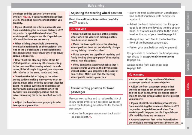
Correct sitting position for driver
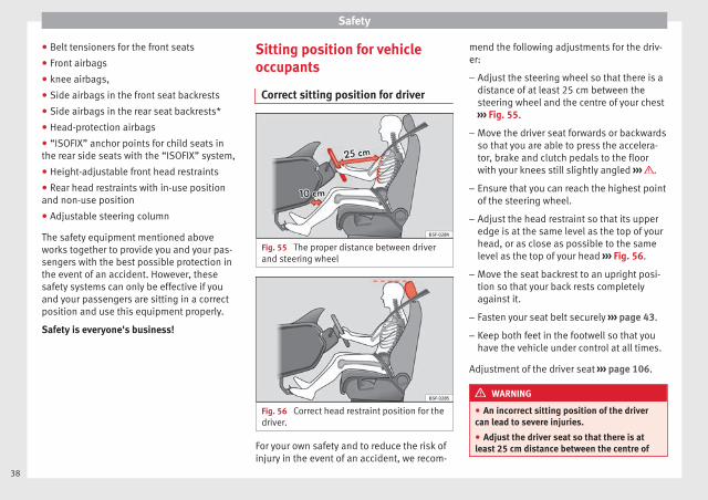
Fig. 55 The proper distance between driverand steering wheel
Fig. 56 Correct head restraint position for thedriver.
For your own safety and to reduce the risk ofinjury in the event of an accident, we recom-
mend the following adjustments for the driv-er:
– Adjust the steering wheel so that there is adistance of at least 25 cm between thesteering wheel and the centre of your chest››› Fig. 55.
– Move the driver seat forwards or backwardsso that you are able to press the accelera-tor, brake and clutch pedals to the floorwith your knees still slightly angled ››› .
– Ensure that you can reach the highest pointof the steering wheel.
– Adjust the head restraint so that its upperedge is at the same level as the top of yourhead, or as close as possible to the samelevel as the top of your head ››› Fig. 56.
– Move the seat backrest to an upright posi-tion so that your back rests completelyagainst it.
– Fasten your seat belt securely ››› page 43.
– Keep both feet in the footwell so that youhave the vehicle under control at all times.
Adjustment of the driver seat ››› page 106.
WARNING
● An incorrect sitting position of the drivercan lead to severe injuries.
● Adjust the driver seat so that there is atleast 25 cm distance between the centre of
38
Safe driving
the chest and the centre of the steeringwheel ››› Fig. 55. If you are sitting closer than25 cm, the airbag system cannot protect youproperly.
● If your physical constitution prevents youfrom maintaining the minimum distance of 25cm, contact a specialised workshop. Theworkshop will help you decide if special spe-cific modifications are necessary.
● When driving, always hold the steeringwheel with both hands on the outside of thering at the 9 o'clock and 3 o'clock positions.This reduces the risk of injury when the driverairbag is triggered.
● Never hold the steering wheel at the 12o'clock position, or in any other manner (e.g.in the centre of the steering wheel). In suchcases, if the airbag is triggered, you may sus-tain injuries to the arms, hands and head.
● To reduce the risk of injury to the driverduring sudden braking manoeuvres or an ac-cident, never drive with the backrest tilted farback! The airbag system and seat belts canonly provide optimal protection when thebackrest is in an upright position and thedriver is wearing his or her seat belt correct-ly.
● Adjust the head restraint properly to ach-ieve optimal protection.
Adjusting the steering wheel position
Read the additional information carefully››› page 14.
WARNING
● Never adjust the position of the steeringwheel when the vehicle is moving, as thiscould cause an accident.
● Move the lever up firmly so the steeringwheel position does not accidentally changeduring driving. risk of accident!
● Make sure you are capable of reaching andfirmly holding the upper part of the steeringwheel: risk of accident!
● If you adjust the steering wheel so that itpoints towards your face, the driver airbagwill not protect you properly in the event ofan accident. Make sure that the steeringwheel points towards your chest.
Correct sitting position for frontpassenger
For your own safety and to reduce the risk ofinjury in the event of an accident, we recom-mend the following adjustments for the frontpassenger:
– Move the front passenger seat back as faras possible ››› .
– Move the seat backrest to an upright posi-tion so that your back rests completelyagainst it.
– Adjust the head restraint so that its upperedge is at the same level as the top of yourhead, or as close as possible to the samelevel as the top of your head ››› page 41.
– Always keep both feet in the footwell infront of the front passenger seat.
– Fasten your seat belt securely ››› page 43.
It is possible to deactivate the front passen-ger airbag in exceptional circumstances››› page 54.
Adjusting the front passenger seat››› page 106.
WARNING
● An incorrect sitting position of the frontpassenger can lead to severe injuries.
● Adjust the front passenger seat so thatthere is at least 25 cm between your chestand the dash panel. If you are sitting closerthan 25 cm, the airbag system cannot protectyou properly.
● If your physical constitution prevents youfrom maintaining the minimum distance of 25cm, contact a specialised workshop. Theworkshop will help you decide if special spe-cific modifications are necessary.
● Always keep your feet in the footwell whenthe vehicle is moving; never rest them on the »
39
Tech
nical
spec
ificati
ons
Adv
ice
Ope
rati
onS
afet
yTh
e es
sent
ials
Safety
dash panel, out the window or on the seat. Anincorrect sitting position exposes you to anincreased risk of injury in case of a suddenbraking or an accident. If the airbag is trig-gered, you could sustain severe injuries dueto an incorrect sitting position.
● To reduce the risk of injury to the front pas-senger in events such as sudden braking ma-noeuvres or an accident, never travel with thebackrest tilted far back! The airbag systemand seat belts can only provide optimal pro-tection when the backrest is in an upright po-sition and the front passenger is wearing hisor her seat belt properly. The further the seatbackrests are tilted to the rear, the greaterthe risk of injury due to incorrect positioningof the belt web or to the incorrect sitting po-sition!
● Adjust the head restraint correctly in orderto achieve maximum protection.
Correct sitting position for passengersin the rear seats
To reduce the risk of injury in the event of asudden braking manoeuvre or an accident,passengers on the rear seat bench must con-sider the following:
– Sit up straight.
– Adjust the head restraint to the correct po-sition ››› page 41.
– Always keep both feet in the footwell infront of the rear seat.
– Fasten your seat belt securely ››› page 43.
– Use an appropriate child restraint systemwhen you take children in the vehicle››› page 56.
WARNING
● If the passengers in the rear seats are notsitting properly, they could sustain severe in-juries.
● Adjust the head restraint correctly in orderto achieve maximum protection.
● Seat belts can only provide optimal protec-tion when seat backrests are in an uprightposition and the vehicle occupants are wear-ing their seat belts correctly. If passengers Inthe rear seats are not sitting in an upright po-sition, the risk of injury due to incorrect posi-tioning of the seat belt increases.
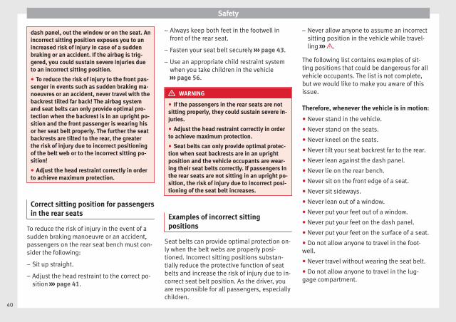
Examples of incorrect sittingpositions
Seat belts can provide optimal protection on-ly when the belt webs are properly posi-tioned. Incorrect sitting positions substan-tially reduce the protective function of seatbelts and increase the risk of injury due to in-correct seat belt position. As the driver, youare responsible for all passengers, especiallychildren.
– Never allow anyone to assume an incorrectsitting position in the vehicle while travel-ling ››› .
The following list contains examples of sit-ting positions that could be dangerous for allvehicle occupants. The list is not complete,but we would like to make you aware of thisissue.
Therefore, whenever the vehicle is in motion:
● Never stand in the vehicle.
● Never stand on the seats.
● Never kneel on the seats.
● Never tilt your seat backrest far to the rear.
● Never lean against the dash panel.
● Never lie on the rear bench.
● Never sit on the front edge of a seat.
● Never sit sideways.
● Never lean out of a window.
● Never put your feet out of a window.
● Never put your feet on the dash panel.
● Never put your feet on the surface of a seat.
● Do not allow anyone to travel in the foot-well.
● Never travel without wearing the seat belt.
● Do not allow anyone to travel in the lug-gage compartment.
40
Safe driving
WARNING
● Any incorrect sitting position increases therisk of severe injuries. Sitting in an incorrectposition exposes the vehicle occupants to se-vere injuries if airbags are triggered, by strik-ing a vehicle occupant who has assumed anincorrect sitting position.
● Before the vehicle moves, assume the prop-er sitting position and maintain it throughoutthe trip. Before every trip, instruct your pas-sengers to sit properly and to stay in this po-sition during the trip ››› page 38, Sitting posi-tion for vehicle occupants.
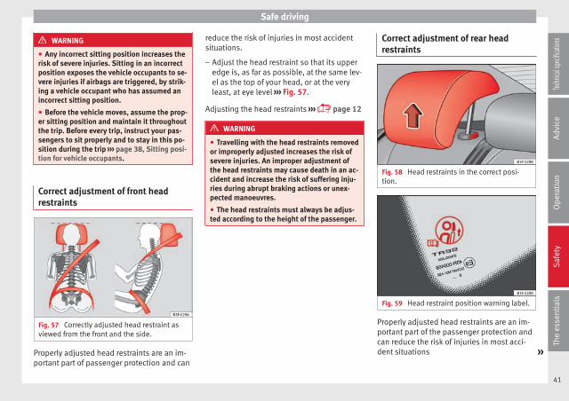
Correct adjustment of front headrestraints
Fig. 57 Correctly adjusted head restraint asviewed from the front and the side.
Properly adjusted head restraints are an im-portant part of passenger protection and can
reduce the risk of injuries in most accidentsituations.
– Adjust the head restraint so that its upperedge is, as far as possible, at the same lev-el as the top of your head, or at the veryleast, at eye level ››› Fig. 57.
Adjusting the head restraints ››› page 12
WARNING
● Travelling with the head restraints removedor improperly adjusted increases the risk ofsevere injuries. An improper adjustment ofthe head restraints may cause death in an ac-cident and increase the risk of suffering inju-ries during abrupt braking actions or unex-pected manoeuvres.
● The head restraints must always be adjus-ted according to the height of the passenger.
Correct adjustment of rear headrestraints
Fig. 58 Head restraints in the correct posi-tion.
Fig. 59 Head restraint position warning label.
Properly adjusted head restraints are an im-portant part of the passenger protection andcan reduce the risk of injuries in most acci-dent situations »
41
Tech
nical
spec
ificati
ons
Adv
ice
Ope
rati
onS
afet
yTh
e es
sent
ials

Safety
Rear head restraints
– The rear head restraints have 2 positions:use and non-use.
– One position for use (head restraint raised)››› Fig. 58. In this position, the head re-straints are used normally, protecting pas-sengers along with the rear seat belts.
– And one position for non-use (head re-straint lowered).
– To fit the head restraints in position for use,pull on the edges with both hands in thedirection of the arrow.
WARNING
● Under no circumstances should the rearpassengers travel while the head restraintsare in the non-use position. See the warninglabel located on the rear side fixed window››› Fig. 59.
● Do not swap the centre rear head restraintwith either of the outer seat rear head re-straints. Risk of injury in case of an accident!
CAUTION
Note the instructions on the adjustment ofthe head restraints ››› page 107.
Pedal area
Pedals
– Ensure that you can always press the accel-erator, brake and clutch pedals unimpairedto the floor.
– Ensure that the pedals can return unim-paired to their initial positions.
– Ensure that the floor mats are securely fas-tened during the trip and do not obstructthe pedals ››› .
Only use floor mats which leave the pedalarea free and can be secured to prevent themfrom slipping. You can obtain suitable floormats from a specialised dealership. Fasten-ers* for floor mats are fitted in the footwells.
If a brake circuit fails, the brake pedal mustbe pressed down thoroughly in order to stopthe vehicle.
Wearing suitable shoes
Always wear shoes which support your feetproperly and give you a good feeling for thepedals.
WARNING
● Restricting pedal operation can lead to crit-ical situations while driving.
● Never lay or fit floor mats or other floor cov-erings over the original floor mats. Thiswould reduce the pedal area and could ob-struct the pedals. Risk of accident.
● Never place objects in the driver footwell.An object could move into the pedal area andimpair pedal operation. In the event of a sud-den driving or braking manoeuvre, you willnot be able to operate the brake, clutch or ac-celerator pedal. Risk of accident!
42

Seat belts
Seat belts
The reasons why we shouldwear seat belts
Number of seats
Your vehicle has five seats, two in the frontand three in the rear. Each seat is equippedwith a three-point seat belt.
In some versions, your vehicle is approvedonly for four seats. Two front seats and tworear seats.
WARNING
● Never transport more than the permittedamount of people in your vehicle.
● Every vehicle occupant must properly fas-ten and wear the seat belt belonging to his orher seat. Children must be protected with anappropriate child restraint system.
Seat belt warning lamp*
Fig. 60 Instrument panel: right rear seat oc-cupied and corresponding seat belt fasteneddisplay.
The control lamp illuminates to remind thedriver to fasten his seat belt.
Before starting the vehicle:
– Fasten your seat belt securely.
– Instruct your passengers to fasten theirseat belts properly before driving off.
– Protect children by using a child seat ac-cording to the child's height and weight.
When the ignition is switched on, the controllamp in the instrument panel lights up (de-pending on the model version) if the driver orpassenger have not fastened their seat belts.
An audible warning signal will sound for afew seconds if the seat belts are not fastenedas the vehicle drives off and reaches a speed
of more than approximately 25 km/h(15 mph) or if the seat belts are unfastenedwhile the vehicle is in motion. The warninglight will also flash .
The lamp goes out when the driver andpassenger seat belts are fastened with the ig-nition switched on.
Rear seat belts fastened display.*
Depending on the model version, when theignition is switched on, the seat belt statusdisplay ››› Fig. 60 on the instrument panel in-forms the driver whether the passengers inthe rear seats have fastened their seat belts.The symbol indicates that the passenger inthis seat has fastened “his or her” seat belt.
When a seat belt in the rear seats is fastenedor unfastened, the seat belt status is dis-played for approximately 30 seconds. The in-dication can be hidden by pressing the0.0/SET button on the dash panel.
The seat belt status flashes for a maximum of30 seconds when a seat belt in the rear seatsis unfastened while the vehicle is in motion.An audible warning will also be heard if thevehicle is travelling at over 25 km/h(15 mph).
43
Tech
nical
spec
ificati
ons
Adv
ice
Ope
rati
onS
afet
yTh
e es
sent
ials
Safety
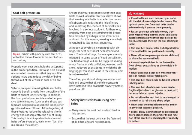
Seat belt protection
Fig. 61 Drivers with properly worn seat beltswill not be thrown forward in the event of sud-den braking
Properly worn seat belts hold the occupantsin the proper position. They also help preventuncontrolled movements that may result inserious injury and reduce the risk of beingthrown out of the vehicle in case of an acci-dent.
Vehicle occupants wearing their seat beltscorrectly benefit greatly from the ability of thebelts to absorb kinetic energy. In addition,the front part of your vehicle and other pas-sive safety features (such as the airbag sys-tem) are designed to absorb the kinetic ener-gy released in a collision. Taken together, allthese features reduce the releasing kineticenergy and consequently, the risk of injury.This is why it is so important to fasten seatbelts before every trip, even when "just driv-ing around the corner".
Ensure that your passengers wear their seatbelts as well. Accident statistics have shownthat wearing seat belts is an effective meansof substantially reducing the risk of injuryand improving the chances of survival wheninvolved in a serious accident. Furthermore,properly worn seat belts improve the protec-tion provided by airbags in the event of anaccident. For this reason, wearing a seat beltis required by law in most countries.
Although your vehicle is equipped with air-bags, the seat belts must be fastened andworn. The front airbags, for example, are onlytriggered in some cases of head-on collision.The front airbags will not be triggered duringminor frontal or side collisions, rear-end colli-sions, rollovers or accidents in which the air-bag trigger threshold value in the control unitis not exceeded.
Therefore, you should always wear your seatbelt and ensure that all vehicle occupantshave fastened their seat belts properly beforeyou drive off!
Safety instructions on using seatbelts
– Always wear the seat belt as described inthis section.
– Ensure that the seat belts can be fastenedat all times and are not damaged.
WARNING
● If seat belts are worn incorrectly or not atall, the risk of severe injuries increases. Theoptimal protection from seat belts can beachieved only if you use them properly.
● Fasten your seat belt before every trip -even when driving in town. Other vehicle oc-cupants must also wear the seat belts at alltimes, otherwise they run the risk of being in-jured.
● The seat belt cannot offer its full protectionif the seat belt is not positioned correctly.
● Never allow two passengers (even children)to share the same seat belt.
● Always keep both feet in the footwell infront of your seat as long as the vehicle is inmotion.
● Never unbuckle a seat belt while the vehi-cle is in motion. Risk of fatal injury.
● The seat belt must never be twisted while itis being worn.
● The seat belt should never lie on hard orfragile objects (such as glasses or pens, etc.)because this can cause injuries.
● Do not allow the seat belt to be damaged orjammed, or to rub on any sharp edges.
● Never wear the seat belt under the arm orin any other incorrect position.
● Loose, bulky clothing (such as an overcoatover a jacket) impairs the proper fit and func-tion of the seat belts, reducing their capacityto protect.
44
Seat belts
● The slot in the seat belt buckle must not beblocked with paper or other objects, as thiscan prevent the latch plate from engaging se-curely.
● Never use seat belt clips, fastening rings orsimilar items to alter the position of the beltwebbing.
● Frayed or torn seat belts or damage to theconnections, belt retractors or parts of thebuckle could cause severe injuries in theevent of an accident. Therefore, you mustcheck the condition of all seat belts at regularintervals.
● Seat belts which have been worn in an acci-dent and stretched must be replaced by aspecialised workshop. Renewal may be nec-essary even if there is no apparent damage.The belt anchorage should also be checked.
● Do not attempt to repair a damaged seatbelt yourself. The seat belts must not be re-moved or modified in any way.
● The belts must be kept clean, otherwise theretractors may not work properly.
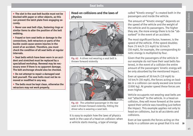
Head-on collisions and the laws ofphysics
Fig. 62 A driver not wearing a seat belt isthrown forward violently
Fig. 63 The unbelted passenger in the rearseat is thrown forward violently, hitting thedriver who is wearing a seat belt.
It is easy to explain how the laws of physicswork in the case of a head-on collision: whena vehicle starts moving, a type of energy
called “kinetic energy” is created both in thepassengers and inside the vehicle.
The amount of “kinetic energy” depends onthe speed of the vehicle and the weight ofthe vehicle and its passengers. The higherthey are, the more energy there is to be “ab-sorbed” in the event of an accident.
The most significant factor, however, is thespeed of the vehicle. If the speed doublesfrom 25 km/h (15 mph) to 50 km/h(30 mph), for example, the corresponding ki-netic energy is multiplied by four.
Given that the passengers of the vehicle inour example do not have their seat belts fas-tened, in the event of a collision the entireamount of the passengers' kinetic energy willbe only absorbed by the mentioned impact.
Even at speeds of 30 km/h (19 mph) to50 km/h (30 mph), the forces acting on bod-ies in a collision can easily exceed one tonne(1000 kg). At greater speed these forces areeven higher.
Vehicle occupants not wearing seat belts arenot “attached” to the vehicle. In a head-oncollision, they will move forward at the samespeed their vehicle was travelling just beforethe impact. This example applies not only tohead-on collisions, but to all accidents andcollisions.
Even at low speeds the forces acting on thebody in a collision are so great that it is not »
45
Tech
nical
spec
ificati
ons
Adv
ice
Ope
rati
onS
afet
yTh
e es
sent
ials
Safety
possible to brace oneself with one's hands.In a frontal collision, unbelted passengersare thrown forward and will make violent con-tact with the steering wheel, dash panel,windscreen or whatever else is in the way››› Fig. 62.
It is also important for rear passengers towear seat belts properly, as they could other-wise be thrown forward violently through thevehicle interior in an accident. Passengers inthe rear seats who do not use seat belts en-danger not only themselves but also the frontoccupants ››› Fig. 63.
How to properly adjust yourseatbelt
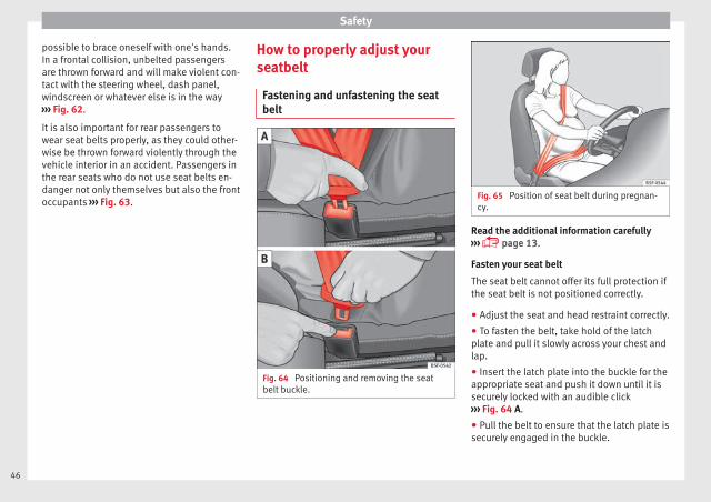
Fastening and unfastening the seatbelt
Fig. 64 Positioning and removing the seatbelt buckle.
Fig. 65 Position of seat belt during pregnan-cy.
Read the additional information carefully››› page 13.
Fasten your seat belt
The seat belt cannot offer its full protection ifthe seat belt is not positioned correctly.
● Adjust the seat and head restraint correctly.
● To fasten the belt, take hold of the latchplate and pull it slowly across your chest andlap.
● Insert the latch plate into the buckle for theappropriate seat and push it down until it issecurely locked with an audible click››› Fig. 64 A.
● Pull the belt to ensure that the latch plate issecurely engaged in the buckle.
46

Seat belts
The seat belts are equipped with an automat-ic retractor on the shoulder strap. Full free-dom of movement is permitted when theshoulder belt is pulled slowly. However, dur-ing sudden braking, during travel in steepareas or bends and during acceleration, theautomatic retractor on the shoulder belt islocked.
The automatic belt retractors on the frontseats are fitted with seat belt tensioners››› page 47.
Releasing the seat belt
● Press the red button on the belt buckle››› Fig. 64 B. The latch plate is released andsprings out ››› .
● Guide the belt back by hand so that it rollsup easily and the trim is not damaged.
Adjusting the seat belt
Seat belts offer their maximum protection on-ly when they are properly positioned››› Fig. 65.
WARNING
● The seat belts offer best protection onlywhen the backrests are in an upright positionand the seat belts have been fastened prop-erly.
● Never put the latch plate in the buckle ofanother seat. If you do this, the seat belt will
not protect you properly and the risk of injuryis increased.
● Never unbuckle a seat belt while the vehi-cle is in motion. If you do, you increase therisk of sustaining severe or fatal injuries.
● An incorrectly worn seat belt can cause se-vere injuries in the event of an accident.
● For pregnant women, the lap part of theseat belt must lie as low as possible over thepelvis, never across the stomach, and alwayslie flat so that no pressure is exerted on theabdomen ››› Fig. 65.
● Always engage the retractor lock when youare securing a child seat in group 0, 0+ or 1››› page 56.
● Read and observe the warnings ››› page 44.
Seat belt tensioners
How the seat belt tensioner works
During a frontal collision, the seat belts onthe front seats are retracted automatically.
The seat belts for the occupants in the frontseats are equipped with belt tensioners. Sen-sors will trigger the belt tensioners only dur-ing severe head-on, lateral and rear-end colli-sions and only if the seat belt is worn. Thisretracts and tightens the seat belts, reducingthe forward motion of the occupants.
The seat belt tensioner can be triggered onlyonce.
The seat belt tensioners will not be triggeredin the event of a light frontal, side or rear col-lision, if the vehicle overturns or in situationswhere no large forces act on the front, side orrear of the vehicle.
Note
● If the seat belt tensioners are triggered, afine dust is produced. This is normal and it isnot an indication of fire in the vehicle.
● The relevant safety requirements must beobserved when the vehicle or components ofthe system are scrapped. Specialised work-shops are familiar with these regulations,which are also available to you.
Service and disposal of belttensioners
The belt tensioners are components of theseat belts that are installed in the seats ofyour vehicle. If you work on the belt tension-ers or remove and install parts of the systemwhen performing other repair work, the seatbelt may be damaged. The consequence maybe that, in the event of an accident, the belttensioners function incorrectly or may notfunction at all.
So that the effectiveness of the seat belt ten-sioner is not reduced and that removed parts »
47
Tech
nical
spec
ificati
ons
Adv
ice
Ope
rati
onS
afet
yTh
e es
sent
ials

Safety
do not cause any injuries or environmentalpollution, regulations, which are known tothe specialised workshops, must be ob-served.
WARNING
● Improper use or repairs not carried out byqualified mechanics increase the risk of se-vere or fatal injuries. The belt tensioners mayfail to trigger or may trigger in the wrong cir-cumstances.
● Never attempt to repair, adjust, remove orinstall parts of the belt tensioners or seatbelts.
● The seat belt tensioner, seat belt and auto-matic retractor cannot be repaired.
● Any work on the belt tensioners and seatbelts, including the removal and refitting ofsystem parts in conjunction with other repairwork, must be performed by a specialisedworkshop only.
● The belt tensioners will only provide pro-tection for one accident and must be changedif they have been activated.
Airbag system
Brief introduction
Why wear a seat belt and assume thecorrect sitting position?
For the inflating airbags to achieve the bestprotection, the seat belt must always be wornproperly and the correct sitting position mustbe assumed.
The airbag system is not a substitute for seatbelts, but it is an integral part of the vehicle'soverall passive safety system. Please bear inmind that the airbag system can only work ef-fectively when the vehicle occupants arewearing their seat belts correctly and haveadjusted the head restraints properly. There-fore, it is most important to properly wear theseat belts at all times, not only because thisis required by law in most countries, but alsofor your safety ››› page 43, The reasons whywe should wear seat belts.
The airbag inflates in a matter of seconds, soif you are not properly seated when the air-bag is triggered, you may sustain fatal inju-ries. Therefore, it is essential that all vehicleoccupants assume a correct sitting positionwhile travelling.
Sharp braking before an accident may causea passenger not wearing a seat belt to bethrown forward into the area of the deploying
airbag. In this case, the inflating airbag mayinflict critical or fatal injuries on the occu-pant. This also applies to children.
Always maintain the greatest possible dis-tance between yourself and the front airbag.This way, the front airbags can completelydeploy when triggered, providing their maxi-mum protection.
The most important factors that will triggeran airbag are: the type of accident, the angleof collision and the speed of the vehicle.
Whether or not the airbags are triggered de-pends primarily on the vehicle decelerationrate resulting from the collision and detectedby the control unit. If the vehicle decelerationoccurring during the collision and measuredby the control unit remains below the speci-fied reference values, the front, side and/orcurtain airbags will not be triggered. Take in-to account that the visible damage in a vehi-cle involved in an accident, no matter howserious, is not a determining factor for theairbags to have been triggered.
WARNING
● Wearing the seat belt incorrectly or assum-ing an incorrect sitting position can lead tocritical or fatal injuries.
● All vehicle occupants, including children,who are not properly belted can sustain criti-cal or fatal injuries if the airbag is triggered.Children up to 12 years old should always
48
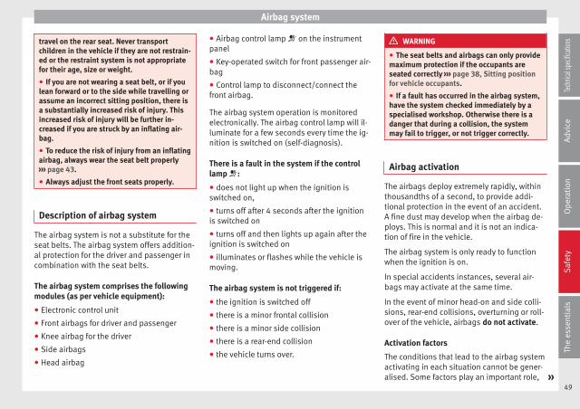
Airbag system
travel on the rear seat. Never transportchildren in the vehicle if they are not restrain-ed or the restraint system is not appropriatefor their age, size or weight.
● If you are not wearing a seat belt, or if youlean forward or to the side while travelling orassume an incorrect sitting position, there isa substantially increased risk of injury. Thisincreased risk of injury will be further in-creased if you are struck by an inflating air-bag.
● To reduce the risk of injury from an inflatingairbag, always wear the seat belt properly››› page 43.
● Always adjust the front seats properly.
Description of airbag system
The airbag system is not a substitute for theseat belts. The airbag system offers addition-al protection for the driver and passenger incombination with the seat belts.
The airbag system comprises the followingmodules (as per vehicle equipment):
● Electronic control unit
● Front airbags for driver and passenger
● Knee airbag for the driver
● Side airbags
● Head airbag
● Airbag control lamp on the instrumentpanel
● Key-operated switch for front passenger air-bag
● Control lamp to disconnect/connect thefront airbag.
The airbag system operation is monitoredelectronically. The airbag control lamp will il-luminate for a few seconds every time the ig-nition is switched on (self-diagnosis).
There is a fault in the system if the controllamp :
● does not light up when the ignition isswitched on,
● turns off after 4 seconds after the ignitionis switched on
● turns off and then lights up again after theignition is switched on
● illuminates or flashes while the vehicle ismoving.
The airbag system is not triggered if:
● the ignition is switched off
● there is a minor frontal collision
● there is a minor side collision
● there is a rear-end collision
● the vehicle turns over.
WARNING
● The seat belts and airbags can only providemaximum protection if the occupants areseated correctly ››› page 38, Sitting positionfor vehicle occupants.
● If a fault has occurred in the airbag system,have the system checked immediately by aspecialised workshop. Otherwise there is adanger that during a collision, the systemmay fail to trigger, or not trigger correctly.
Airbag activation
The airbags deploy extremely rapidly, withinthousandths of a second, to provide addi-tional protection in the event of an accident.A fine dust may develop when the airbag de-ploys. This is normal and it is not an indica-tion of fire in the vehicle.
The airbag system is only ready to functionwhen the ignition is on.
In special accidents instances, several air-bags may activate at the same time.
In the event of minor head-on and side colli-sions, rear-end collisions, overturning or roll-over of the vehicle, airbags do not activate.
Activation factors
The conditions that lead to the airbag systemactivating in each situation cannot be gener-alised. Some factors play an important role, »
49
Tech
nical
spec
ificati
ons
Adv
ice
Ope
rati
onS
afet
yTh
e es
sent
ials
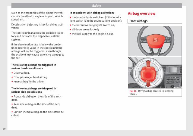
Safety
such as the properties of the object the vehi-cle hits (hard/soft), angle of impact, vehiclespeed, etc.
Deceleration trajectory is key for airbag acti-vation.
The control unit analyses the collision trajec-tory and activates the respective restraintsystem.
If the deceleration rate is below the prede-fined reference value in the control unit theairbags will not be triggered, even thoughthe accident may cause extensive damage tothe car.
The following airbags are triggered inserious head-on collisions
● Driver airbag.
● Front passenger front airbag
● Knee airbag for the driver.
The following airbags are triggered inserious side-on collisions
● Front side airbag on the side of the acci-dent.
● Rear side airbag on the side of the acci-dent.
● Curtain (head) airbag on the side of the ac-cident.
In an accident with airbag activation:
● the interior lights switch on (if the interiorlight switch is in the courtesy light position);
● the hazard warning lights switch on;
● all doors are unlocked;
● the fuel supply to the engine is cut.
Airbag overview
Front airbags
Fig. 66 Driver airbag located in steeringwheel.
50
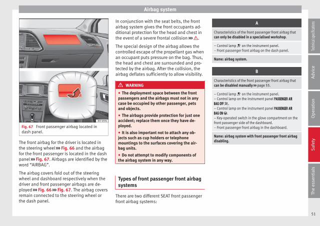
Airbag system
Fig. 67 Front passenger airbag located indash panel.
The front airbag for the driver is located inthe steering wheel ››› Fig. 66 and the airbagfor the front passenger is located in the dashpanel ››› Fig. 67. Airbags are identified by theword “AIRBAG”.
The airbag covers fold out of the steeringwheel and dashboard respectively when thedriver and front passenger airbags are de-ployed ››› Fig. 66 ››› Fig. 67. The airbag coversremain connected to the steering wheel orthe dash panel.
In conjunction with the seat belts, the frontairbag system gives the front occupants ad-ditional protection for the head and chest inthe event of a severe frontal collision ››› .
The special design of the airbag allows thecontrolled escape of the propellant gas whenan occupant puts pressure on the bag. Thus,the head and chest are surrounded and pro-tected by the airbag. After the collision, theairbag deflates sufficiently to allow visibility.
WARNING
● The deployment space between the frontpassengers and the airbags must not in anycase be occupied by other passenger, petsand objects.
● The airbags provide protection for just oneaccident; replace them once they have de-ployed.
● It is also important not to attach any ob-jects such as cup holders or telephonemountings to the surfaces covering the air-bag units.
● Do not attempt to modify components ofthe airbag system in any way.
Types of front passenger front airbagsystems
There are two different SEAT front passengerfront airbag systems:
A
Characteristics of the front passenger front airbag thatcan only be disabled in a specialised workshop.
– Control lamp on the instrument panel.– Front passenger front airbag on the dash panel.
Name: airbag system.
B
Characteristics of the front passenger front airbag thatcan be disabled manually ››› page 55.
– Control lamp on the instrument panel.– Control lamp on the instrument panel .– Control lamp on the instrument panel .– Key-operated switch in the glove compartment on thefront passenger side of the dashboard.– Front passenger front airbag in the dashboard.
Name: airbag system with front passenger front airbagdisabling.
51
Tech
nical
spec
ificati
ons
Adv
ice
Ope
rati
onS
afet
yTh
e es
sent
ials

Safety
Knee airbag*
Fig. 68 On the driver side: location of theknee airbag
Fig. 69 On the driver side: radius of action ofthe knee airbag.
The knee airbag is located on the driver sidebelow the dash panel ››› Fig. 68. Airbags areidentified by the word “AIRBAG”.
The area framed in red ››› Fig. 69 is coveredby the knee airbag when it is deployed (de-
ployment area). Therefore, objects shouldnever be placed or mounted in these areas.
WARNING
● The knee airbag is deployed in front of thedriver's knees. Always keep the deploymentareas of the knee airbags free.
● Never not fix objects to the cover or in thedeployment area of the knee airbag.
● Adjust the driver seat so that there is a dis-tance of at least 10 cm (4 inches) betweenyour knees and the location of the this air-bag. If your physical constitution preventsyou from meeting these requirements, makesure you contact a specialised workshop.
Side airbags*
Fig. 70 Side airbag in driver seat.
Fig. 71 Illustration of completely inflated sideairbags on the left side of the vehicle.
The side airbags are located in the backrestcushions of the driver seat ››› Fig. 70 and thefront passenger seat as well as in the back-rest of the side rear seats*. The locations areidentified by the text “AIRBAG” in the upperregion of the backrests.
Together with the seat belts, the side airbagsystem gives the front seat occupants addi-tional protection for the upper body in theevent of a severe side collision ››› .
In a side collision, the side airbags reducethe risk of injury to passengers on the frontseats to the areas of the body facing the im-pact. In addition to their normal function ofprotecting the occupants in a collision, theseat belts also hold the passengers in thefront seats and the outer rear seats in a posi-tion where these airbags can provide maxi-mum protection.
52

Airbag system
WARNING
● If you do not wear a seat belt, if you leanforward, or are not seated correctly while thevehicle is in motion, you are at a greater riskof injury if the side airbag system is triggeredin an accident.
● In order for the side airbags to provide theirmaximum protection, the prescribed sittingposition must always be maintained withseat belts fastened while travelling.
● In a side-on collision the side airbags willnot work if the sensors do not correctly meas-ure the pressure increase on the interior ofthe doors, due to air escaping through theareas with holes or openings in the door pan-el.
● Never drive if the interior door panels havebeen removed or if the panels have not beencorrectly fitted.
● Never drive the vehicle if the loudspeakersin the door panels have been removed, un-less the holes left by the loudspeakers havebeen closed properly.
● Always check that the openings are closedor covered if loudspeakers or other equip-ment are fitted inside the door panels.
● Occupants of the outer seats must nevercarry any objects or pets in the deploymentspace between them and the airbags, or al-low children or other passengers to travel inthis position. It is also important not to at-tach any accessories (such as cup holders) to
the doors. This would impair the protectionoffered by the side airbags.
● The built-in coat hooks should be used onlyfor lightweight clothing. Do not leave anyheavy or sharp-edged objects in the pockets.
● Great forces, such as hard blows or kicks,must not be exerted upon the backrest bol-ster because the system may be damaged. Inthis case, the side airbags would not be trig-gered.
● Under no circumstances should protectivecovers be fitted over seats with side airbagsunless the covers have been approved for usein your vehicle. Because the airbag deploysfrom the side of the backrest, the use of con-ventional seat covers would obstruct the sideairbag, seriously reducing the airbag's effec-tiveness.
● Any damage to the original seat upholsteryor around the seams of the side airbag unitsmust be repaired immediately by a special-ised workshop.
● The airbags provide protection for just oneaccident; replace them once they have de-ployed.
● Any work on the side airbag system or re-moval and installation of the airbag compo-nents for other repairs (such as removal ofthe front seat) should only be performed by aspecialised workshop. Otherwise, faults mayoccur during the airbag system operation.
● Do not attempt to modify components ofthe airbag system in any way.
Head-protection airbags*
Fig. 72 Location of head-protection airbags.
The head-protection airbags are located onboth sides in the interior above the doors››› Fig. 72 and are identified with the text“AIRBAG”.
In conjunction with the seat belts, the head-protection airbag system gives the vehicleoccupants additional protection for the headand upper body in the event of a severe sidecollision ››› .
WARNING
● In order for the head-protection airbags toprovide their maximum protection, the pre-scribed sitting position must always be main-tained with seat belts fastened while travel-ling.
● For safety reasons, the curtain airbag mustbe disabled in those vehicles fitted with ascreen dividing the interior of the vehicle. »
53
Tech
nical
spec
ificati
ons
Adv
ice
Ope
rati
onS
afet
yTh
e es
sent
ials

Safety
See your technical service to make this ad-justment.
● There must be no other persons, animals orobjects between the occupants of the outerseats and the deployment space of the head-protection airbags so that the head-protec-tion airbag can deploy completely without re-striction and provide the greatest possibleprotection. Therefore, sun blinds which havenot been expressly approved for use in yourvehicle may not be attached to the side win-dows
● The built-in coat hooks should be used onlyfor lightweight clothing. Do not leave anyheavy or sharp-edged objects in the pockets.Please, do not hang the clothes on coat hang-ers.
● The airbags provide protection for just oneaccident; replace them once they have de-ployed.
● Any work on the head-protection airbagsystem or removal and installation of the air-bag components for other repairs (such as re-moval of the roof lining) should only be per-formed by a specialised workshop. Other-wise, faults may occur during the airbag sys-tem operation.
● Do not attempt to modify components ofthe airbag system in any way.
● The side and head airbags are managedthrough sensors located in the interior of thefront doors. To ensure the correct operation ofthe side and curtain airbags neither thedoors nor the door panels should be modifiedin any way (e.g. fitting loudspeakers). If the
front door is damaged, the airbag systemmay not work correctly. All work carried outon the front door must be done in a special-ised workshop.
Deactivating airbags
Disabling the front airbag
Fig. 73 Control lamp for disabling the frontpassenger front airbag on the dash panel
It lights up on the combi-in-strument
Fault in airbagsystem and seatbelt tensioners.
Have the system checked immedi-ately by a specialised workshop.
It lights up on the dash panel
Fault in the air-bag system.
Have the system checked immedi-ately by a specialised workshop.
Front passengerfront airbag dis-abled.
Check whether the airbag should re-main disabled.
It lights up on the dash panel
Front passengerfront airbag ena-bled.
The control lamp switches off about60 seconds after the ignition isturned on or after enabling of thefront passenger front airbag with thekey lock switch.
Several warning and control lamps light upfor a few seconds when the ignition is switch-ed on, signalling that the function is beingverified. They will switch off after a few sec-onds.
If the front passenger airbag is deactivated,the lamp does not re-main lit, or if it is lit together with the controllamp on the dash panel, there may be afault in the airbag system ››› .
The disabling of airbags is only carried out incertain cases, i.e. if:
● a child seat is required in the front passen-ger seat with the child facing in the oppositedirection to the direction of travel (in some
54
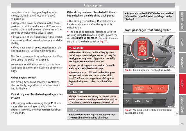
Airbag system
countries, due to divergent legal require-ments, facing in the direction of travel)››› page 58;
● despite the driver seat being in the correctposition, a minimum distance of 25 cm can-not be maintained between the centre of thesteering wheel and the driver's torso,
● installation of special devices is required inthe steering wheel area due to a physical dis-ability,
● if you have special seats installed (e.g. anorthopaedic seat without side airbags).
The front passenger front airbag can be disa-bled using the switch ››› page 55.
We recommend that you contact an author-ised SEAT dealer for the disabling of other air-bags.
Airbag system control
The airbag system availability is controlledelectronically, regardless of whether an air-bag is disabled.
If an airbag was disabled using a diagnosticssystem:
● the airbag system warning lamp illumi-nates after switching on the ignition forabout 4 seconds, and then flashes for about12 seconds.
If the airbag has been disabled with the air-bag switch on the side of the dash panel:
● the airbag control lamp will illuminatefor about 4 seconds after the ignition isswitched on,
● The airbag is disabled, signalled with thewarning lamp which lights up with theword placed in the cen-tre part of the dash panel ››› Fig. 74.
WARNING
In the event of a fault in the airbag system,the airbag may not trigger correctly, may failto trigger or may even trigger unexpectedly,leading to severe or fatal injuries.
● Have the airbag system checked immedi-ately by a specialised workshop.
● Never mount a child seat in the front pas-senger seat or remove the mounted childseat! The front passenger front airbag maydeploy during an accident in spite of thefault.
CAUTION
Always pay attention to any lit control lampsand to the corresponding descriptions and in-structions to avoid damage to the vehicle.
Note
● Follow the current legislation in your coun-try regarding the disabling of airbags.
● At your authorised SEAT dealer you can findinformation on which vehicle airbags can bedisabled.
Front passenger front airbag switch
Fig. 74 Front passenger front airbag switch.
Fig. 75 Warning lamp for disabling the frontpassenger airbag. »
55
Tech
nical
spec
ificati
ons
Adv
ice
Ope
rati
onS
afet
yTh
e es
sent
ials
Safety
Read the additional information carefully››› page 11.
The switch disables only the front passengerfront airbag.
Switching on the airbag
– Switch the ignition off.
– Open the glove compartment on the frontpassenger side.
– Insert the key into the slot of the switch fordeactivating the front passenger airbag››› Fig. 74. About 3/4 of the key should en-ter, as far as it will go.
– Then turn the key gently to the ON position.Do not force it if you feel resistance, andmake sure you have inserted the key fully.
– Close the passenger side storage compart-ment.
– Check, with the ignition switched on, thatthe control lamp ››› Fig. 75 does notlight up, with the word in the centre part of the dash panel.
– The warning lamp is illuminated for60 seconds in the centre part of the dashpanel.
Control lamp with the word (front passenger airbag disabled)
If the front passenger front airbag is disa-bled, after switching on the ignition, the con-
trol lamp will light up for several seconds,then it will switch off for about 1 s and thenswitch on again.
If the control lamp is flashing, there is a faultin the disabling of the airbag system ››› .Please go immediately to an Official Service.
WARNING
● The driver of the vehicle is responsible fordisabling or switching on the airbag.
● Always switch off the ignition before disa-bling the front passenger airbag! Failure to doso could result in a fault in the airbag deacti-vation system.
● Never leave the key in the airbag disablingswitch as it could get damaged or enable ordisable the airbag during driving.
● If the (airbag disabled) control lampflashes, the front passenger front airbag willnot trigger in the event of an accident! Havethe system immediately checked by an Offi-cial Service.
Transporting children safety
Safety for children
Introduction
For safety reasons, as we have learned fromaccident statistics, we recommend that chil-dren under 12 years of age travel in the rearseats. Depending on their age, height andweight, children travelling in rear seats mustuse a child seat or a seat belt. For safety rea-sons, the child seat should be installed in therear seat, behind the front passenger seat orin the centre back seat.
The physical laws involved and the forcesacting in a collision apply also to children››› page 45. But unlike adults, children do nothave fully developed muscle and bone struc-tures. This means that children are subject toa greater risk of injury.
To reduce the risk of injuries, children mustalways use special child restraint systemswhen travelling in the vehicle.
We recommend the use of child safety prod-ucts from the SEAT Original Accessories Pro-gramme, which includes systems for all agesmade by “Peke” (not for all countries).
These systems have been especially de-signed and approved, complying with theECE-R44. regulation.
56
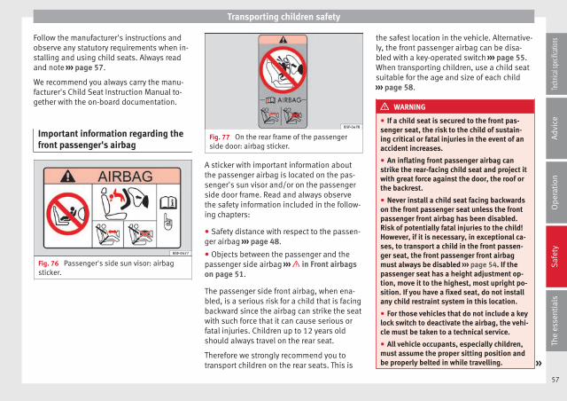
Transporting children safety
Follow the manufacturer's instructions andobserve any statutory requirements when in-stalling and using child seats. Always readand note ››› page 57.
We recommend you always carry the manu-facturer's Child Seat Instruction Manual to-gether with the on-board documentation.
Important information regarding thefront passenger's airbag
Fig. 76 Passenger's side sun visor: airbagsticker.
Fig. 77 On the rear frame of the passengerside door: airbag sticker.
A sticker with important information aboutthe passenger airbag is located on the pas-senger's sun visor and/or on the passengerside door frame. Read and always observethe safety information included in the follow-ing chapters:
● Safety distance with respect to the passen-ger airbag ››› page 48.
● Objects between the passenger and thepassenger side airbag ››› in Front airbagson page 51.
The passenger side front airbag, when ena-bled, is a serious risk for a child that is facingbackward since the airbag can strike the seatwith such force that it can cause serious orfatal injuries. Children up to 12 years oldshould always travel on the rear seat.
Therefore we strongly recommend you totransport children on the rear seats. This is
the safest location in the vehicle. Alternative-ly, the front passenger airbag can be disa-bled with a key-operated switch ››› page 55.When transporting children, use a child seatsuitable for the age and size of each child››› page 58.
WARNING
● If a child seat is secured to the front pas-senger seat, the risk to the child of sustain-ing critical or fatal injuries in the event of anaccident increases.
● An inflating front passenger airbag canstrike the rear-facing child seat and project itwith great force against the door, the roof orthe backrest.
● Never install a child seat facing backwardson the front passenger seat unless the frontpassenger front airbag has been disabled.Risk of potentially fatal injuries to the child!However, if it is necessary, in exceptional ca-ses, to transport a child in the front passen-ger seat, the front passenger front airbagmust always be disabled ››› page 54. If thepassenger seat has a height adjustment op-tion, move it to the highest, most upright po-sition. If you have a fixed seat, do not installany child restraint system in this location.
● For those vehicles that do not include a keylock switch to deactivate the airbag, the vehi-cle must be taken to a technical service.
● All vehicle occupants, especially children,must assume the proper sitting position andbe properly belted in while travelling. »
57
Tech
nical
spec
ificati
ons
Adv
ice
Ope
rati
onS
afet
yTh
e es
sent
ials
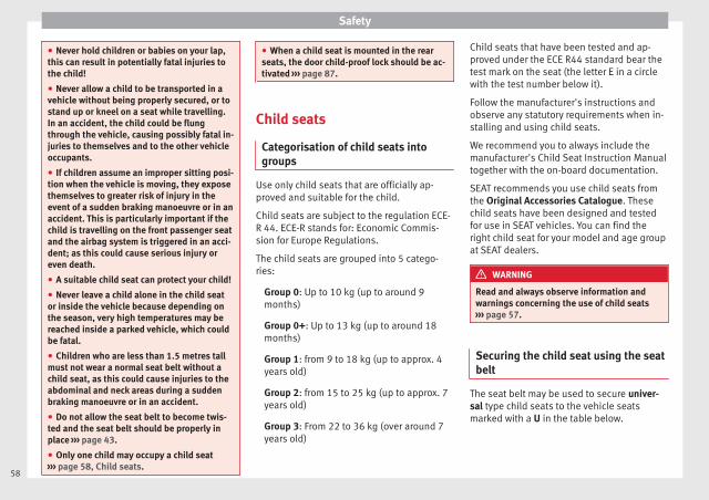
Safety
● Never hold children or babies on your lap,this can result in potentially fatal injuries tothe child!
● Never allow a child to be transported in avehicle without being properly secured, or tostand up or kneel on a seat while travelling.In an accident, the child could be flungthrough the vehicle, causing possibly fatal in-juries to themselves and to the other vehicleoccupants.
● If children assume an improper sitting posi-tion when the vehicle is moving, they exposethemselves to greater risk of injury in theevent of a sudden braking manoeuvre or in anaccident. This is particularly important if thechild is travelling on the front passenger seatand the airbag system is triggered in an acci-dent; as this could cause serious injury oreven death.
● A suitable child seat can protect your child!
● Never leave a child alone in the child seator inside the vehicle because depending onthe season, very high temperatures may bereached inside a parked vehicle, which couldbe fatal.
● Children who are less than 1.5 metres tallmust not wear a normal seat belt without achild seat, as this could cause injuries to theabdominal and neck areas during a suddenbraking manoeuvre or in an accident.
● Do not allow the seat belt to become twis-ted and the seat belt should be properly inplace ››› page 43.
● Only one child may occupy a child seat››› page 58, Child seats.
● When a child seat is mounted in the rearseats, the door child-proof lock should be ac-tivated ››› page 87.
Child seats
Categorisation of child seats intogroups
Use only child seats that are officially ap-proved and suitable for the child.
Child seats are subject to the regulation ECE-R 44. ECE-R stands for: Economic Commis-sion for Europe Regulations.
The child seats are grouped into 5 catego-ries:
Group 0: Up to 10 kg (up to around 9months)
Group 0+: Up to 13 kg (up to around 18months)
Group 1: from 9 to 18 kg (up to approx. 4years old)
Group 2: from 15 to 25 kg (up to approx. 7years old)
Group 3: From 22 to 36 kg (over around 7years old)
Child seats that have been tested and ap-proved under the ECE R44 standard bear thetest mark on the seat (the letter E in a circlewith the test number below it).
Follow the manufacturer's instructions andobserve any statutory requirements when in-stalling and using child seats.
We recommend you to always include themanufacturer's Child Seat Instruction Manualtogether with the on-board documentation.
SEAT recommends you use child seats fromthe Original Accessories Catalogue. Thesechild seats have been designed and testedfor use in SEAT vehicles. You can find theright child seat for your model and age groupat SEAT dealers.
WARNING
Read and always observe information andwarnings concerning the use of child seats››› page 57.
Securing the child seat using the seatbelt
The seat belt may be used to secure univer-sal type child seats to the vehicle seatsmarked with a U in the table below.
58
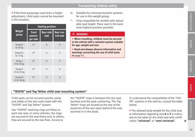
Transporting children safety
● If the front passenger seat lacks a heightadjustment, child seats cannot be mountedis this location.
Weightgroup
Seating position
Frontpassen-ger seat
Rear sideseat
Rear cen-tral seat
Group 0to 10 kg
U* U U
Group 0+to 13 kg
U* U U
Group I9 to 18 kg
U* U U
Group II15 to 25 kg
U* U U
Group III22 to 36 kg
U* U U
Suitable for universal restraint systemsfor use in this weight group.
Only compatible for models with adjust-able seat height. Place seat in the back-most highest position possible.
WARNING
● When travelling, children must be securedin the vehicle with a restraint system suitablefor age, weight and size.
● Read and always observe information andwarnings concerning the use of child seats››› page 57.
U:
*:
“ISOFIX” and Top Tether child seat mounting system*
Child seats can be secured quickly, easilyand safely on the rear outer seats with the“ISOFIX” and Top Tether* system.
Two “ISOFIX” retaining rings are fitted oneach rear seat. In some vehicles, the ringsare secured to the seat frame and, in others,they are secured to the rear floor. Access to
the “ISOFIX” rings is between the rear seatbackrest and the seat cushioning. The TopTether* rings are located at the rear of thebackrests of the rear seats (behind the seatbackrest or in the boot).
To understand the compatibility of the "ISO-FIX" systems in the vehicle, consult the tablebelow.
● The allowed body weight for the child seator information regarding size A to F is indica-ted on the label on the child seat with certifi-cation “universal” or “semi-universal”. »
59
Tech
nical
spec
ificati
ons
Adv
ice
Ope
rati
onS
afet
yTh
e es
sent
ials
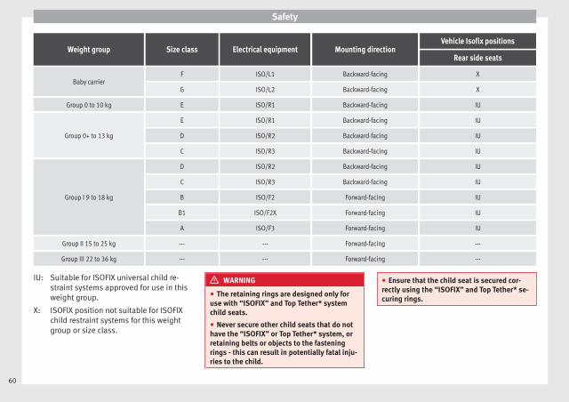
Safety
Weight group Size class Electrical equipment Mounting directionVehicle Isofix positions
Rear side seats
Baby carrierF ISO/L1 Backward-facing X
G ISO/L2 Backward-facing X
Group 0 to 10 kg E ISO/R1 Backward-facing IU
Group 0+ to 13 kg
E ISO/R1 Backward-facing IU
D ISO/R2 Backward-facing IU
C ISO/R3 Backward-facing IU
Group I 9 to 18 kg
D ISO/R2 Backward-facing IU
C ISO/R3 Backward-facing IU
B ISO/F2 Forward-facing IU
B1 ISO/F2X Forward-facing IU
A ISO/F3 Forward-facing IU
Group II 15 to 25 kg --- --- Forward-facing ---
Group III 22 to 36 kg --- --- Forward-facing ---
Suitable for ISOFIX universal child re-straint systems approved for use in thisweight group.
ISOFIX position not suitable for ISOFIXchild restraint systems for this weightgroup or size class.
IU:
X:
WARNING
● The retaining rings are designed only foruse with “ISOFIX” and Top Tether* systemchild seats.
● Never secure other child seats that do nothave the “ISOFIX” or Top Tether* system, orretaining belts or objects to the fasteningrings - this can result in potentially fatal inju-ries to the child.
● Ensure that the child seat is secured cor-rectly using the “ISOFIX” and Top Tether* se-curing rings.
60
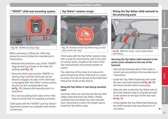
Transporting children safety
“ISOFIX” child seat mounting system
Fig. 78 ISOFIX securing rings.
When removing or fitting the child seat,please be sure to follow the manufacturer'sinstructions.
– Remove the protective caps of the “ISOFIX”rings by placing a finger in the hole andpulling up ››› Fig. 78.
– Press the child seat onto the “ISOFIX” re-taining rings until the child seat can beheard to engage securely. If the child seatis equipped with Top Tether* anchor points,secure it to the correspondent ring››› Fig. 79. Observe the manufacturer's in-structions.
– Do a test by pulling both sides of the childseat to ensure that it is properly anchored.
Child seats with the “ISOFIX” and Top Tether*attachment system are available from Techni-cal Services.
Top Tether* retainer straps
Fig. 79 Position of the Top Tether rings on theback of the rear seat.
Child seats with the Top Tether system comewith a strap for securing the seat to the vehi-cle anchor point, located at the back of therear seat backrest and provide greater re-straint.
The objective of this strap is to reduce for-ward movements of the child seat in a crash,to reduce the risk of injuries to the head fromhitting the inside of the vehicle.
Using the Top Tether in rear-facing mountedseats
Currently, there are very few rear-facing childsafety seats that have Top Tether. Pleasecarefully read and follow the seat manufac-turer instructions to learn the proper way toinstall the Top Tether strap.
Fitting the Top Tether child restraint tothe anchoring point
Fig. 80 Retainer strap: correct adjustmentand fitting.
Securing the Top Tether child restraint to theanchor point situated on the rear of thebackrest
– Pull out the fastening belt of the child re-straint seat according to the manufacturer'sinstructions.
– Guide the Top Tether fastening belt underthe rear seat head restraint ››› Fig. 80 (liftthe head restraint where necessary).
– Slide the belt so that the Top Tether belt ofthe child restraint seat is correctly securedto the anchor on the back of the rear seat››› Fig. 79.
– Firmly tighten the Top Tether belt followingthe child restraint seat manufacturer's in-structions. »
61
Tech
nical
spec
ificati
ons
Adv
ice
Ope
rati
onS
afet
yTh
e es
sent
ials
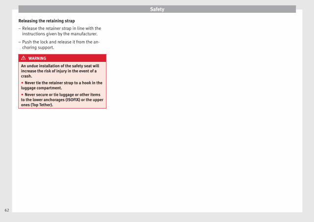
Safety
Releasing the retaining strap
– Release the retainer strap in line with theinstructions given by the manufacturer.
– Push the lock and release it from the an-choring support.
WARNING
An undue installation of the safety seat willincrease the risk of injury in the event of acrash.
● Never tie the retainer strap to a hook in theluggage compartment.
● Never secure or tie luggage or other itemsto the lower anchorages (ISOFIX) or the upperones (Top Tether).
62


Operation
Fig. 81 Instruments and controls.
64
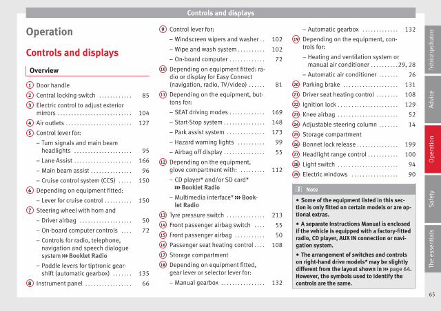
Controls and displays
Operation
Controls and displays
Overview
Door handle
Central locking switch . . . . . . . . . . . . 85
Electric control to adjust exteriormirrors . . . . . . . . . . . . . . . . . . . . . . . . . . . 104
Air outlets . . . . . . . . . . . . . . . . . . . . . . . . 127
Control lever for:
– Turn signals and main beamheadlights . . . . . . . . . . . . . . . . . . . . . 95
– Lane Assist . . . . . . . . . . . . . . . . . . . . . 166
– Main beam assist . . . . . . . . . . . . . . . 96
– Cruise control system (CCS) . . . . . 150
Depending on equipment fitted:
– Lever for cruise control . . . . . . . . . . 150
Steering wheel with horn and
– Driver airbag . . . . . . . . . . . . . . . . . . . 50
– On-board computer controls . . . . 72
– Controls for radio, telephone,navigation and speech dialoguesystem ››› Booklet Radio
– Paddle levers for tiptronic gear-shift (automatic gearbox) . . . . . . . 135
Instrument panel . . . . . . . . . . . . . . . . . 66
1
2
3
4
5
6
7
8
Control lever for:
– Windscreen wipers and washer . . 102
– Wipe and wash system . . . . . . . . . . 102
– On-board computer . . . . . . . . . . . . . 72
Depending on equipment fitted: ra-dio or display for Easy Connect(navigation, radio, TV/video) . . . . . . 81
Depending on the equipment, but-tons for:
– SEAT driving modes . . . . . . . . . . . . . 169
– Start-Stop system . . . . . . . . . . . . . . . 148
– Park assist system . . . . . . . . . . . . . . 173
– Hazard warning lights . . . . . . . . . . 99
– Airbag off display . . . . . . . . . . . . . . . 55
Depending on the equipment,glove compartment with: . . . . . . . . . 112
– CD player* and/or SD card*››› Booklet Radio
– Multimedia interface* ››› Book-let Radio
Tyre pressure switch . . . . . . . . . . . . . . 213
Front passenger airbag switch . . . . 55
Front passenger airbag . . . . . . . . . . . 50
Passenger seat heating control . . . . 108
Storage compartment
Depending on equipment fitted,gear lever or selector lever for:
– Manual gearbox . . . . . . . . . . . . . . . . 132
9
10
11
12
13
14
15
16
17
18
– Automatic gearbox . . . . . . . . . . . . . 132
Depending on the equipment, con-trols for:
– Heating and ventilation system ormanual air conditioner . . . . . . . . . .29, 28
– Automatic air conditioner . . . . . . . 26
Parking brake . . . . . . . . . . . . . . . . . . . . 131
Driver seat heating control . . . . . . . . 108
Ignition lock . . . . . . . . . . . . . . . . . . . . . . 129
Knee airbag . . . . . . . . . . . . . . . . . . . . . . 52
Adjustable steering column . . . . . . . 14
Storage compartment
Bonnet lock release . . . . . . . . . . . . . . . 199
Headlight range control . . . . . . . . . . . 100
Light switch . . . . . . . . . . . . . . . . . . . . . . 94
Electric windows . . . . . . . . . . . . . . . . . 90
Note
● Some of the equipment listed in this sec-tion is only fitted on certain models or are op-tional extras.
● A separate Instructions Manual is enclosedif the vehicle is equipped with a factory-fittedradio, CD player, AUX IN connection or navi-gation system.
● The arrangement of switches and controlson right-hand drive models* may be slightlydifferent from the layout shown in ››› page 64.However, the symbols used to identify thecontrols are the same.
19
20
21
22
23
24
25
26
27
28
29
65
Tech
nical
spec
ificati
ons
Adv
ice
Ope
rati
onS
afet
yTh
e es
sent
ials
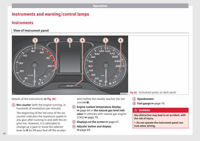
Operation
Instruments and warning/control lamps
Instruments
View of instrument panel
Fig. 82 Instrument panel, on dash panel
Details of the instruments ››› Fig. 82:
Rev counter (with the engine running, inhundreds of revolutions per minute).
The beginning of the red zone of the revcounter indicates the maximum speed inany gear after running-in and with the en-gine hot. However, it is advisable tochange up a gear or move the selectorlever to D (or lift your foot off the acceler-
1
ator) before the needle reaches the redzone ››› .
Engine coolant temperature display››› page 69 or the natural gas level indi-cator in vehicles with natural gas engine(CNG) ››› page 70.
Displays on the screen ››› page 67.
Adjuster button and display››› page 69.
2
3
4
Speedometer.
Fuel gauge ››› page 70.
WARNING
Any distraction may lead to an accident, withthe risk of injury.
● Do not operate the instrument panel con-trols when driving.
5
6
66

Instruments and warning/control lamps
CAUTION
● To prevent damage to the engine, the revcounter needle should only remain in the redzone for a short period of time.
● When the engine is cold, avoid high revsand heavy acceleration and do not make theengine work hard.
For the sake of the environment
Changing up a gear in time reduces fuel con-sumption and noise.
Rev counter
The rev counter indicates the number of en-gine revolutions per minute ››› Fig. 82 1 .
Together with the gear-change indicator, therev counter offers you the possibility of usingthe engine of your vehicle at a suitablespeed.
The start of the red zone on the dial indicatesthe maximum engine speed which may beused briefly when the engine is warm and af-ter it has been run in properly. Before reach-ing this range, you should change to a highergear for vehicles with a manual gearbox or forautomatic gearboxes put the selector lever in“D” or take your foot off the accelerator ped-al.
We recommend that you avoid high revs andthat you follow the recommendations on thegear-change indicator. Consult the additionalinformation in ››› page 74, Gear-change in-dicator.
CAUTION
Never allow the rev counter needle 1
››› Fig. 82 to go into the red zone on the scalefor more than a very brief period, otherwisethere is a risk of engine damage.
For the sake of the environment
Changing up a gear early will help you to savefuel and minimise emissions and enginenoise.
Displays on screen
Fig. 83 A: bonnet open; B: rear lid open; C:front left door open; D: rear right door open(5-door vehicles only).
A variety of information can be viewed on theinstrument panel display ››› Fig. 82 3 de-pending on the vehicle equipment:
● Bonnet, rear lid and doors open ››› Fig. 83.
● Information and warning texts.
● Mileage. »
67
Tech
nical
spec
ificati
ons
Adv
ice
Ope
rati
onS
afet
yTh
e es
sent
ials
Operation
● Time.
● Navigation instructions.
● Outside temperature.
● Compass.
● Shift lever position ››› page 133.
● Recommended gear (manual gearbox)››› page 74.
● Multifunction display (MFD) and menuswith different setting options ››› page 72.
● Service interval display ››› page 80.
● Second speed display ››› page 72.
● Speed warning function ››› page 79.
● Start-Stop system status display››› page 148.
● Low consumption driving status (ECO)››› page 69
● Identifying letters on engine (MKB).
● Active cylinder management display(ACT®)* ››› page 142
Mileage
The odometer registers the total distancetravelled by the car.
The odometer (trip) shows the distance trav-elled since the last odometer reset. The lastdigit of the trip recorder indicates distancesof 100 metres or one tenths of a mile.
● Briefly press the button ››› Fig. 82 4 to re-set the trip recorder to 0.
● Keep the button 4 pressed for about 3seconds and the previous value will be dis-played.
Time
● To set the time, keep the button ››› Fig. 824 pressed for more than 3 seconds to select
the hour or minute display.
● To continue setting the time, press the up-per or lower part of the button 4 . Hold but-ton down to scroll through the numbersquickly.
● Press the button 4 again in order to finishsetting the time.
The time can also be set via the key andSetup function button in the Easy Connect
system ››› page 81.
Compass
With the ignition on and the navigation sys-tem on, the cardinal point corresponding tothe direction of travel of the vehicle is dis-played on the instrument panel.
Selector lever position
The selected gear is displayed on the side ofthe selector lever and on the instrument pan-el display. In positions D and S, and with theTiptronic, the corresponding gear is also dis-played.
Recommended gear (manual gearbox)
The recommended gear in order to save fuelis displayed on the instrument panel whileyou are driving ››› page 74.
Second speed display (mph or km/h)
In addition to the speedometer, the speedcan also be displayed in a different unit ofmeasurement (in miles or in km per hour).
This option cannot be deactivated in modelsdestined for countries in which the secondspeed must always be visible.
The second speed display can be adjusted inthe Easy Connect system via the key andthe Setup function button ››› page 81.
Speed warning
When the speed setting is exceeded, this willbe indicated on the instrument panel display.This is very useful, for example when usingwinter tyres that are not designed for drivingat the maximum speed of the vehicle››› page 79.
The speed warning settings can be adjustedin the Easy Connect system via the keyand the Setup function button ››› page 81.
Start-Stop operating display.
Updated information relating to the status isdisplayed on the instrument panel››› page 148.
68
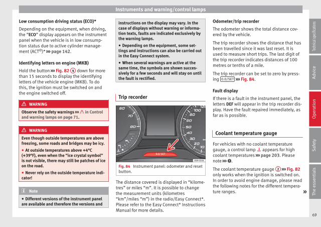
Instruments and warning/control lamps
Low consumption driving status (ECO)*
Depending on the equipment, when driving,the “ECO” display appears on the instrumentpanel when the vehicle is in low consump-tion status due to active cylinder manage-ment (ACT®)* ››› page 142.
Identifying letters on engine (MKB)
Hold the button ››› Fig. 82 4 down for morethan 15 seconds to display the identifyingletters of the vehicle engine (MKB). To dothis, the ignition must be switched on andthe engine switched off.
WARNING
Observe the safety warnings ››› in Controland warning lamps on page 71.
WARNING
Even though outside temperatures are abovefreezing, some roads and bridges may be icy.
● At outside temperatures above +4°C(+39°F), even when the “ice crystal symbol”is not visible, there may still be patches of iceon the road.
● Never rely on the outside temperature indi-cator!
Note
● Different versions of the instrument panelare available and therefore the versions and
instructions on the display may vary. In thecase of displays without warning or informa-tion texts, faults are indicated exclusively bythe warning lamps.
● Depending on the equipment, some set-tings and instructions can also be carried outin the Easy Connect system.
● When several warnings are active at thesame time, the symbols are shown succes-sively for a few seconds and will stay on untilthe fault is rectified.
Trip recorder
Fig. 84 Instrument panel: odometer and resetbutton.
The distance covered is displayed in “kilome-tres” or miles “m”. It is possible to changethe measurement units (kilometres“km”/miles “m”) in the radio/Easy Connect*.Please refer to the Easy Connect* InstructionsManual for more details.
Odometer/trip recorder
The odometer shows the total distance cov-ered by the vehicle.
The trip recorder shows the distance that hasbeen travelled since it was last reset. It isused to measure short trips. The last digit ofthe trip recorder indicates distances of 100metres or tenths of a mile.
The trip recorder can be set to zero by press-ing 0.0/SET ››› Fig. 84.
Fault display
If there is a fault in the instrument panel, theletters DEF will appear in the trip recorder dis-play. Have the fault repaired immediately, asfar as is possible.
Coolant temperature gauge
For vehicles with no coolant temperaturegauge, a control lamp appears for highcoolant temperatures ››› page 203. Pleasenote ››› .
The coolant temperature gauge 2 ››› Fig. 82only works when the ignition is switched on.In order to avoid engine damage, please readthe following notes for the different tempera-ture ranges. »
69
Tech
nical
spec
ificati
ons
Adv
ice
Ope
rati
onS
afet
yTh
e es
sent
ials
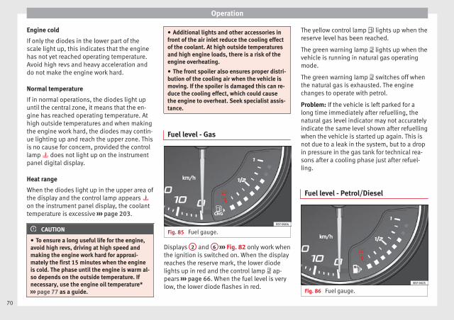
Operation
Engine cold
If only the diodes in the lower part of thescale light up, this indicates that the enginehas not yet reached operating temperature.Avoid high revs and heavy acceleration anddo not make the engine work hard.
Normal temperature
If in normal operations, the diodes light upuntil the central zone, it means that the en-gine has reached operating temperature. Athigh outside temperatures and when makingthe engine work hard, the diodes may contin-ue lighting up and reach the upper zone. Thisis no cause for concern, provided the controllamp does not light up on the instrumentpanel digital display.
Heat range
When the diodes light up in the upper area ofthe display and the control lamp appears on the instrument panel display, the coolanttemperature is excessive ››› page 203.
CAUTION
● To ensure a long useful life for the engine,avoid high revs, driving at high speed andmaking the engine work hard for approxi-mately the first 15 minutes when the engineis cold. The phase until the engine is warm al-so depends on the outside temperature. Ifnecessary, use the engine oil temperature*››› page 77 as a guide.
● Additional lights and other accessories infront of the air inlet reduce the cooling effectof the coolant. At high outside temperaturesand high engine loads, there is a risk of theengine overheating.
● The front spoiler also ensures proper distri-bution of the cooling air when the vehicle ismoving. If the spoiler is damaged this can re-duce the cooling effect, which could causethe engine to overheat. Seek specialist assis-tance.
Fuel level - Gas
Fig. 85 Fuel gauge.
Displays 2 and 6 ››› Fig. 82 only work whenthe ignition is switched on. When the displayreaches the reserve mark, the lower diodelights up in red and the control lamp ap-pears ››› page 66. When the fuel level is verylow, the lower diode flashes in red.
The yellow control lamp lights up when thereserve level has been reached.
The green warning lamp lights up when thevehicle is running in natural gas operatingmode.
The green warning lamp switches off whenthe natural gas is exhausted. The enginechanges to operate with petrol.
Problem: If the vehicle is left parked for along time immediately after refuelling, thenatural gas level indicator may not accuratelyindicate the same level shown after refuellingwhen the vehicle is started up again. This isnot due to a leak in the system, but to a dropin pressure in the gas tank for technical rea-sons after a cooling phase just after refuel-ling.
Fuel level - Petrol/Diesel
Fig. 86 Fuel gauge.
70

Instruments and warning/control lamps
The display 6 ››› Fig. 82 only works whenthe ignition is switched on. When the displayreaches the reserve mark, the lower diodelights up in red and the control lamp ap-pears ››› page 66. When the fuel level is verylow, the lower diode flashes in red.
The distance to empty fuel level is displayedon the instrument panel 3 ››› Fig. 82.
The capacity of the fuel tank of your vehicle isgiven in the Technical data section››› page 268.
CAUTION
Never run the fuel tank completely dry. An ir-regular fuel supply could cause misfiring. Inthis way the unburned fuel can reach the ex-haust system, which could cause the catalyticconverter to overheat resulting in damage.
Control lamps
Control and warning lamps
Read the additional information carefully››› page 22.
The control and warning lamps are indicatorsof warnings, ››› , faults ››› or certain func-tions. Some control and warning lamps comeon when the ignition is switched on, andswitch off when the engine starts running, orwhile driving.
Depending on the model, additional textmessages may be viewed on the instrumentpanel display. These may be purely informa-tive or they may be advising of the need foraction ››› page 66, Instruments.
Depending upon the equipment fitted in thevehicle, instead of a warning lamp, some-times a symbol may be displayed on the in-strument panel.
When certain control and warning lamps arelit, an audible warning is also heard.
WARNING
If the warning lamps and messages are ignor-ed, the vehicle may stall in traffic, or maycause accidents and severe injuries.
● Never ignore the warning lamps or textmessages.
● Stop the vehicle safely as soon as possible.
● Park the vehicle away from traffic and en-sure that there are no highly flammable ma-terials under the vehicle that could come intocontact with the exhaust system (e.g. drygrass, fuel).
● A faulty vehicle represents a risk of acci-dent for the driver and for other road users. Ifnecessary, switch on the hazard warninglamps and put out the warning triangle to ad-vise other drivers.
● Before opening the bonnet, switch off theengine and allow it to cool.
● In any vehicle, the engine compartment is ahazardous area and could cause severe inju-ries ››› page 198.
CAUTION
Failure to heed the control lamps and textmessages when they appear may result infaults in the vehicle.
Engine management*
This warning lamp monitors the engine man-agement system for petrol engines.
The warning lamp (Electronic Power Con-trol) lights up when the ignition is switchedon while system operation is being verified. Itshould go out once the engine is started.
If there is a fault in the electronic enginemanagement system while you are driving,this warning lamp will light up. Stop the vehi-cle and seek technical assistance.
Glow plug system/Engine fault*
The warning lamp lights up to show that theglow plugs are preheating the diesel engine.
The control lamp lights up
If the control lamp lights up when the en-gine is started it means that the glow plugs »
71
Tech
nical
spec
ificati
ons
Adv
ice
Ope
rati
onS
afet
yTh
e es
sent
ials

Operation
are preheating. When the warning lamp goesoff, the engine should be started straightaway.
Control lamp flashes
If a fault develops in the engine managementsystem while you are driving, the glow plugsystem lamp will flash . Take the vehicle toa specialised workshop as soon as possibleand have the engine checked.
Driver information system
Information system
Introduction
With the ignition switched on, it is possibleto read the different functions of the displayby scrolling through the menus.
In vehicles with multifunction steering wheel,the multifunction display can only be operat-ed with the steering wheel buttons.
The number of menus displayed on the in-strument panel will vary according to the ve-hicle electronics and equipment.
A specialised workshop will be able to pro-gramme or modify additional functions, ac-cording to the vehicle equipment. SEAT rec-ommends visiting a SEAT Official Service.
Some menu options can only be read whenthe vehicle is at a standstill.
As long as a priority 1 warning is displayed, itwill not be possible to read the menus. Somewarning messages can be confirmed andmade to disappear with the windscreen wiperlever button or the multifunction steeringwheel button.
The information system also provides the fol-lowing information and displays (dependingon the vehicle's equipment):
Driving data ››› page 76
■ Vehicle status■ MFD from departure■ MFD from refuelling■ MFD total calculation
Assist systems ››› table on page 74
■ Activate/deactivate Lane Assist■ Reverse (optional)
Navigation ››› Booklet Navigation system
Audio ››› Booklet Radio or ››› Booklet Naviga-tion system
Telephone ››› Booklet Radio or ››› Book-let Navigation system
Vehicle ››› table on page 74
WARNING
Any distraction may lead to an accident, withthe risk of injury.
● Do not operate the instrument panel con-trols when driving.
72

Driver information system
Operating the instrument panelmenus
Fig. 87 Windscreen wiper lever: control but-tons.
Fig. 88 Right side of multifunction steeringwheel: control buttons.
Read the additional information carefully››› page 19
The driver information system is controlledwith the multifunction steering wheel buttons
››› Fig. 88 or with the windscreen wiper lever››› Fig. 87 (if the vehicle is not equipped withmultifunction steering wheel).
Enabling the main menu
● Switch the ignition on.
● If a message or vehicle pictogram appears,press button ››› Fig. 87 1 on the windscreenwiper lever or button on the multifunctionsteering wheel ››› Fig. 88.
● If managed from the windscreen wiper lev-er: to display the main screen ››› page 74 orto return to the main menu from anothermenu hold down the rocker button ››› Fig. 87
2 .
● If managed from the multifunction steeringwheel: the main menu list is not displayed.To go from point to point in the main menu,press button or several times››› Fig. 88.
Select a submenu
● Press the rocker switch ››› Fig. 87 2 on thewindscreen wiper lever up or down or turnthe thumbwheel of the multifunction steeringwheel ››› Fig. 88 until the desired option ap-pears marked on the menu.
● The selected option is displayed betweentwo horizontal lines. In addition, a triangle isdisplayed on the right:
● To consult the submenu option, press but-ton ››› Fig. 87 1 on the windscreen wiper
lever or button on the multifunction steer-ing wheel ››› Fig. 88.
Making changes according to the menu
● With the rocker switch on the windscreenwiper lever or the thumbwheel of the multi-function steering wheel, make the desiredchanges. To increase or decrease the valuesmore quickly, turn the thumbwheel faster.
● Mark or confirm the selection with button››› Fig. 87 1 on the windscreen wiper leveror button on the multifunction steeringwheel ››› Fig. 88.
Button for the driving assistancesystems*
Fig. 89 On the turn signal and main beamheadlight lever: button for the driving assis-tance systems »
73
Tech
nical
spec
ificati
ons
Adv
ice
Ope
rati
onS
afet
yTh
e es
sent
ials
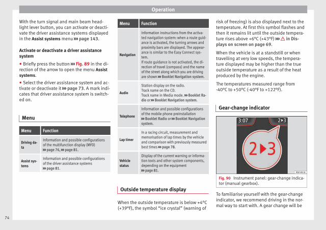
Operation
With the turn signal and main beam head-light lever button, you can activate or deacti-vate the driver assistance systems displayedin the Assist systems menu ››› page 143.
Activate or deactivate a driver assistancesystem
● Briefly press the button ››› Fig. 89 in the di-rection of the arrow to open the menu Assistsystems.
● Select the driver assistance system and ac-tivate or deactivate it ››› page 73. A mark indi-cates that driver assistance system is switch-ed on.
Menu
Menu Function
Driving da-ta
Information and possible configurationsof the multifunction display (MFD)››› page 76, ››› page 81.
Assist sys-tems
Information and possible configurationsof the driver assistance systems››› page 81.
Menu Function
Navigation
Information instructions from the activa-ted navigation system: when a route guid-ance is activated, the turning arrows andproximity bars are displayed. The appear-ance is similar to the Easy Connect sys-tem.If route guidance is not activated, the di-rection of travel (compass) and the nameof the street along which you are drivingare shown ››› Booklet Navigation system.
Audio
Station display on the radio.Track name on the CD.Track name in Media mode. ››› Booklet Ra-dio or ››› Booklet Navigation system.
Telephone
Information and possible configurationsof the mobile phone preinstallation››› Booklet Radio or ››› Booklet Navigationsystem.
Lap timer
In a racing circuit, measurement andmemorisation of lap times by the vehicleand comparison with previously measuredbest times ››› page 78.
Vehiclestatus
Display of the current warning or informa-tion texts and other system components,depending on the equipment››› page 81.
Outside temperature display
When the outside temperature is below +4°C(+39°F), the symbol “ice crystal” (warning of
risk of freezing) is also displayed next to thetemperature. At first this symbol flashes andthen it remains lit until the outside tempera-ture rises above +6°C (+43°F) ››› in Dis-plays on screen on page 69.
When the vehicle is at a standstill or whentravelling at very low speeds, the tempera-ture displayed may be higher than the trueoutside temperature as a result of the heatproduced by the engine.
The temperatures measured range from-40°C to +50°C (-40°F to +122°F).
Gear-change indicator
Fig. 90 Instrument panel: gear-change indica-tor (manual gearbox).
To familiarise yourself with the gear-changeindicator, we recommend driving in the nor-mal way to start with. A gear change will be
74

Driver information system
recommended if the gear you are in is not themost economical choice.
If no gear-change is recommended, it meansthat you are already in the most economicalgear.
Vehicles with a manual gearbox
The following display symbols ››› Fig. 90mean:
● Change to a higher gear: the suggestedgear appears to the right of the current gearwhen a higher gear is recommended.
● Change to a lower gear: the suggestedgear appears to the left of the current gearwhen a lower gear is recommended.
The gear recommendation may occasionallyskip a gear (2nd 4th).
Vehicles with an automatic gearbox*
The display is only visible in tiptronic mode››› page 135.
The following display symbols mean:
● Shifting up a gear
● Shifting down a gear
CAUTION
The gear-change indicator is intended to helpsave fuel, but it is not intended to recom-mend the right gear for all driving situations.
In certain situations, only the driver canchoose the correct gear (for instance whenovertaking, driving up a steep gradient ortowing a trailer).
Note
The display disappears from the instrumentpanel when you press the clutch pedal.
Bonnet, rear lid and doors open
When the ignition is switched on or whendriving, the bonnet, rear lid or doors that areopen will be indicated on the instrument pan-el display, and if it should be the case, thiswill also be indicated audibly. The displaymay vary according to the type of instrumentpanel fitted.
Illustra-tion
Key to ››› Fig. 83
A Do not continue driving!The bonnet is open or is not properlyclosed ››› page 198.
B Do not continue driving!The rear lid is open or is not properlyclosed ››› page 89.
C, D Do not continue driving!A vehicle door is open or is not properlyclosed ››› page 82.
Warning and information texts
The system runs a check on certain compo-nents and functions when the ignition isswitched on and while the vehicle is moving.Faults in the operation are displayed on thescreen using red and yellow symbols andmessages on the instrument panel display(››› page 71) and, in some cases, with audiblewarnings. The display may vary according tothe type of instrument panel fitted.
Priority 1 warning (red symbols)
Symbol flashing or lit; partly combined with audiblewarnings. Stop the vehicle! It is dangerous ››› in Control andwarning lamps on page 71 !Check the function that is faulty and repair it. If necessa-ry, request assistance from specialised personnel.
Priority 2 warning (yellow symbols)
Symbol flashing or lit; partly combined with audiblewarnings.A faulty function, or fluids which are below the correctlevels may cause damage to the vehicle! ››› in Controland warning lamps on page 71Check the faulty function as soon as possible. If neces-sary, request assistance from specialised personnel.
Informative text
Information relating to different vehicle processes.
75
Tech
nical
spec
ificati
ons
Adv
ice
Ope
rati
onS
afet
yTh
e es
sent
ials
Operation
Assist systems submenu
Assistsystemsmenu
Function
Lane As-sist*
Switching the Lane Assist system on or off››› page 168.
Tirednessdetection*
Switching the tiredness detection on or off(pause recommendation) ››› page 172.
Driving data
Presets
The MFD (multifunction display) shows differ-ent values for the journey and the consump-tion.
Changing between display modes on theMFD
● In vehicles without multifunction steeringwheel: Press the rocker switch on thewindscreen wiper lever ››› Fig. 87.
● Vehicles with a multifunction steeringwheel: turn the thumbwheel ››› Fig. 88.
Multifunction display memory
The multifunction display is equipped withthree memories that work automatically: MFDfrom departure, MFD from refuelling, MFD to-
tal calculation. On the screen display, youcan read which memory is currently dis-played.
To change between memories with the igni-tion on and the memory shown, press thebutton on the windscreen wiper leveror you can also change between memoriesusing the button on the multifunctionsteering wheel.
Menu Function
MFD fromdepar-ture
Display and storage of the values for thejourney and the consumption from when theignition is switched on to when it is switch-ed off.If the journey is continued in less than 2hours after the ignition is switched off, thenew data is added to the data already stor-ed in the memory. The memory will auto-matically be deleted if the journey is inter-rupted for more than 2 hours.
MFD fromrefuelling
Display and storage of the values for thejourney and the consumption. By refuelling,the memory will be erased automatically.
MFD totalcalcula-tion
The memory records the values for a specif-ic number of partial trips, up to a total of 19hours and 59 minutes or 99 hours and 59minutes, or 1999.9 km or 9999 km, de-pending on the model of instrument panel.On reaching either of these limitsa), thememory is automatically erased and startsto count from 0 again.
a) It varies according to the type of instrument panel fitted.
Erasing a memory manually
● Select the memory that you wish to erase.
● Hold the button of the multifunctionsteering wheel or the button of the multi-function wheel pressed down for about 2 sec-onds.
Personalising the displays
In the Easy Connect system you can adjustwhich of the possible displays of the MFD canbe shown on the instrument panel displaywith the button and the function buttonSetup ››› page 81.
Data summary
Menu Function
Current fuelconsumption
The current fuel consumption displayoperates throughout the journey, in li-tres/100 km; and with the engine run-ning and the vehicle stopped, in li-tres/hour.
Average fuelconsumptiona)
After turning on the ignition, averagefuel consumption in litres/100 km willbe displayed after travelling about 100metres. Otherwise horizontal lines aredisplayed. The value shown is updatedapproximately every 5 seconds.ACT®*: Depending on the equipment,number of active cylinders.
76

Driver information system
Menu Function
Operatingrangea)
Approximate distance in km that canstill be travelled with the fuel remain-ing in the tank, assuming the samestyle of driving is maintained. This iscalculated using the current fuel con-sumption.
Journey dura-tion
This indicates the hours (h) and mi-nutes (min) since the ignition wasswitched on.
Distance cov-ered
Distance covered in km (m) afterswitching on the ignition.
CNG quality
Whenever you refuel the quality of thenatural gas is automatically verifiedand is displayed when the ignition isswitched on. The display is made in apercentage of between 70% and100%. The greater the percentage dis-played the lower the consumption maybe.
Average speed
The average speed will be shown aftera distance of about 100 metres hasbeen travelled. Otherwise horizontallines are displayed. The value shown isupdated approximately every 5 sec-onds.
Digital displayof speed
Current speed displayed in digital for-mat.
Speed warn-ing at --- km/hor Speedwarning at ---mph
If the stored speed is exceeded (be-tween 30 - 250 km/h, or 19 -155 mph), an audible warning is giventogether with a visual warning.
Menu Function
Oil tempera-ture
Updated engine oil temperature digitaldisplay
Coolant tem-peraturegauge
Digital display of the current tempera-ture of the liquid coolant.
a) In vehicles with a natural gas engine, range and average con-sumption refer only to data or natural gas consumption. If youare in “petrol mode”, the information of both data only appearson the dash panel and not on the multifunction screen.
Storing a speed for the speed warning
● Select the display Speed warning at --- km/h(--- mph)
● Press the button on the windscreenwiper lever or the button on the multifunc-tion steering wheel to store the current speedand activate the warning.
● If necessary, adjust the desired speed with-in 5 seconds using the rocker switch onthe windscreen wiper lever or by turning thethumbwheel on the multifunction steeringwheel. Next, press the button or again or wait several seconds. The speed isstored and the warning activated.
● To deactivate it press the button orthe button . The stored speed is deleted.
Engine oil temperature display
Vehicles without multifunction steeringwheel
– To view the temperature, press the rockerbutton ››› Fig. 87 2 until the main menucomes up. Enter into Journey data. With thebutton 2 move to the oil temperaturegauge.
Vehicles with multifunction steering wheel
– To display the engine oil temperature, enterthe submenu Journey data and turn thethumbwheel until the oil temperature dis-play appears.
The engine reaches its operating temperaturewhen in normal driving conditions, the oiltemperature is between 80°C (180°F) and120°C (250°F). If the engine is required towork hard and the outside temperature ishigh, the engine oil temperature can in-crease. This does not present any problemsas long as the warning lamps ››› ta-ble on page 23 or ››› table on page 23do not appear on the display.
Additional electrical appliances3 Not available in vehicles equipped with naturalgas engine (CNG).
– Operation with the windscreen wiper lev-er*: Press the rocker switch ››› Fig. 87 2 »
77
Tech
nical
spec
ificati
ons
Adv
ice
Ope
rati
onS
afet
yTh
e es
sent
ials
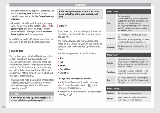
Operation
until the main menu appears. Enter into thesection Journey data. With the rockerswitch, move to the display Convenience ap-pliances.
– Operation with the multifunction steeringwheel*: Move with the buttons 1 or 2 toJourney data and enter with OK. Turn thethumbwheel to the right until the Conven-ience appliances display appears.
In addition, a scale will inform you of the cur-rent sum of all the additional appliances.
Saving tips
Tips on how to save fuel will be displayed incertain conditions that contribute to in-creased consumption. Following these tipscould reduce the fuel consumption of yourvehicle. The displays appear automaticallyand will only be shown with the efficiencyprogramme. After a time, the saving tips willdisappear automatically.
– If you wish to hide a saving tip immediatelyafter it appears, press any button on thewindscreen wiper lever*/multifunctionsteering wheel*.
Note
● If you hide a saving tip, it will reappear af-ter you switch the ignition on again.
● The saving tips do not appear in all situa-tions, but rather with a large separation oftime.
Timer*
If you have the corresponding equipment youcan access the timer via the selection menu››› page 74.
The timer allows you to manually time laptimes on a racing circuit, memorise them andcompare then to the vehicle's previous besttimes.
The following menus can be displayed:
● Stop
● Lap
● Pause
● Partial time
● Statistics
Change from one menu to another
● Vehicles without multifunction steeringwheel: press the rocker switch in thewindscreen wiper lever.
● Vehicles with multifunction steering wheel:press or .
Menu “Stop”
Start
The timer starts.If there are existing laps and they are in-cluded in the statistics, it will begin withthe number of laps in question.It is only possible to begin with a new firstlap if the statistics have been reset first inthe Statistics menu.
Since start
The timer begins when the vehicle setsoff.If the vehicle is already moving, the timerbegins once the vehicle has stopped.
StatisticsThe Statistics menu is displayed on thescreen.
Menu “Lap”
New lap
The timer of the current lap stops and anew lap starts immediately. The time forthe lap you have just completed is inclu-ded in the statistics.
Partial timeFor about 5 seconds a partial time is dis-played. The timer continues in parallel.
StopThe current lap timer will be interrupted.The lap does not end. The Pause menu isdisplayed.
Menu “Pause”
Continue The interrupted timer continues.
New lapA new timer starts. The halted lap endsand is included in the statistics.
78
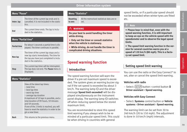
Driver information system
Menu “Pause”
Interr. lapThe timer of the current lap ends and iscancelled. It is not included in the statis-tics.
EndThe current timer ends. The lap is inclu-ded in the statistics.
Menu “Partial time”
Partial timeFor about 5 seconds a partial time is dis-played. The timer continues in parallel.
New lap
The timer of the current lap stops and anew lap starts immediately. The time forthe lap you have just completed is inclu-ded in the statistics.
StopThe current lap timer will be interrupted.The lap does not end. The Pause menu isdisplayed.
Menu “Statistics”
View of the latest lap times:– total time– best lap time– worst lap time– average lap durationA maximum of 10 laps is possible, and atotal duration of 99 hours, 59 minutesand 59 seconds.If one of the 2 limits is reached, you willhave to reset the statistics in order to be-gin a new timer.
Back This returns to the previous menu.
Menu “Statistics”
Resettingto zero
All the memorised statistical data are re-set.
WARNING
Do your best to avoid handling the timerwhile driving.
● Only set the timer or consult statisticswhen the vehicle is stationary.
● While driving, do not handle the timer incomplicated driving situations.
Speed warning function
Introduction
The speed warning function will warn thedriver if a pre-set maximum speed is excee-ded. The system gives an warning buzzer sig-nal if the set speed is exceeded by about 3km/h. The warning lamp and the drivermessage Speed limit exceeded! will be dis-played simultaneously on the instrumentpanel display. The warning lamp switchesoff when reducing speed below the storedmaximum limit.
You are recommended to store this speedlimit warning if you always wish to be re-minded of a particular speed limit. This couldbe when driving in countries with general
speed limits, or if a particular speed shouldnot be exceeded when winter tyres are fittedetc.
Note
● Please bear in mind that, even with thespeed warning function, it is still importantto keep an eye on the vehicle speed with thespeedometer and to observe the legal speedlimits.
● The speed limit warning function in the ver-sion for several countries warns you at aspeed of 120 km/h (80 mph). This is a facto-ry-set speed limit.
Setting speed limit warning
You can use the radio or the Easy Connect* toset, alter or cancel the speed limit warning.
Vehicles with radio
– Select: SETUP button > control button Driver assistant > Speed warning.
Vehicles with Easy Connect
– Select: Systems control button or Vehiclesystems > Driver assistant > Speed warning.
The warning limit can be set from 30 to240 km/h (20 to 150 mph). The adjustmentis done in 10 km/h (mph) intervals.
79
Tech
nical
spec
ificati
ons
Adv
ice
Ope
rati
onS
afet
yTh
e es
sent
ials

Operation
Service interval display
Service interval display
The service interval indication appears on theinstrument panel display ››› Fig. 82 4 .
SEAT distinguishes between services with en-gine oil change (e.g. Oil change service) andservices without engine oil change (e.g. In-spection).
In vehicles with Services established by timeor mileage, the service intervals are alreadypre-defined.
In vehicles with LongLife Service, the inter-vals are determined individually. Technicalprogress has made it possible to considera-bly reduce servicing requirements. The tech-nology used by SEAT ensures that your vehi-cle only has an Oil Servicing when it is neces-sary. To establish when the oil servicing isdue (max. 2 years), the vehicle's conditionsof use and individual driving styles are con-sidered. The service pre-warning first ap-pears 20 days before the date established forthe corresponding service. The kilometres(miles) remaining until the next service arealways rounded up to the nearest 100 km(miles) and the time is given in completedays. The current service message cannot beviewed until 500 km after the last service. Pri-or to this only lines are visible on the display.
Inspection reminder
When the Service date is approaching, whenthe ignition is switched on a Service remind-er is displayed.
In vehicles without text messages, a spanneris displayed on the instrument panel witha figure given in km. The number of kilome-tres shown is the maximum number that maybe driven until the next service. After a fewseconds, the display mode changes. A clocksymbol appears and the number of days untilthe next service appointment is due.
In vehicles with text messages, Service in ---km (miles) or --- days is displayed on the in-strument panel.
Service due
After the service date, an audible warning isgiven when the ignition is switched on andthe spanner displayed on the screen flashesfor a few seconds . In vehicles with textmessages, Service in --- km or --- days is dis-played on the instrument panel.
Reading a service notification
With the ignition switched on, the engine offand the vehicle at a standstill, the currentservice notification can be read:
Press and hold the button ››› Fig. 82 4 formore than 5 seconds to consult the servicemessage.
When the service date has past, a minus signis displayed in front of the number of kilome-tres or days. In vehicles with text messagesthe following is displayed: Service --- km(miles) or --- days ago.
The time can also be set via the key andSetup function button in the Easy Connect
system ››› page 81.
Resetting service interval display
If the service was not carried out by a SEATdealership, the display can be reset as fol-lows:
● To reset the service interval display, turnthe ignition off and press and hold the but-ton ››› Fig. 82 4 .
● Switch the ignition back on.
● Release the button ››› Fig. 82 4 and pressthe button 4 again for the next 20 seconds.
Note
● The service message disappears after a fewseconds, when the engine is started or whenOK/RESET is pressed on the windscreen wiper
lever, or OK on the multifunction steeringwheel.
● In vehicles with the LongLife system inwhich the battery has been disconnected fora long period of time, it is not possible to cal-culate the date of the next service. Thereforethe service interval display may not be cor-rect. In this case, bear in mind the maximum
80
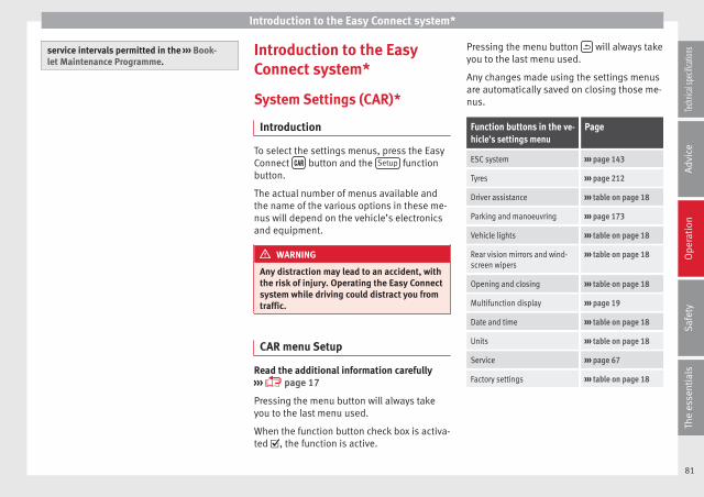
Introduction to the Easy Connect system*
service intervals permitted in the ››› Book-let Maintenance Programme.
Introduction to the EasyConnect system*
System Settings (CAR)*
Introduction
To select the settings menus, press the EasyConnect button and the Setup functionbutton.
The actual number of menus available andthe name of the various options in these me-nus will depend on the vehicle’s electronicsand equipment.
WARNING
Any distraction may lead to an accident, withthe risk of injury. Operating the Easy Connectsystem while driving could distract you fromtraffic.
CAR menu Setup
Read the additional information carefully››› page 17
Pressing the menu button will always takeyou to the last menu used.
When the function button check box is activa-ted , the function is active.
Pressing the menu button will always takeyou to the last menu used.
Any changes made using the settings menusare automatically saved on closing those me-nus.
Function buttons in the ve-hicle’s settings menu
Page
ESC system ››› page 143
Tyres ››› page 212
Driver assistance ››› table on page 18
Parking and manoeuvring ››› page 173
Vehicle lights ››› table on page 18
Rear vision mirrors and wind-screen wipers
››› table on page 18
Opening and closing ››› table on page 18
Multifunction display ››› page 19
Date and time ››› table on page 18
Units ››› table on page 18
Service ››› page 67
Factory settings ››› table on page 18
81
Tech
nical
spec
ificati
ons
Adv
ice
Ope
rati
onS
afet
yTh
e es
sent
ials
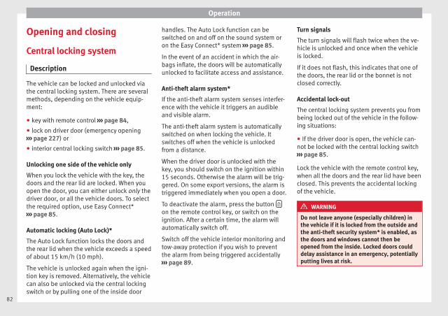
Operation
Opening and closing
Central locking system
Description
The vehicle can be locked and unlocked viathe central locking system. There are severalmethods, depending on the vehicle equip-ment:
● key with remote control ››› page 84,
● lock on driver door (emergency opening››› page 227) or
● interior central locking switch ››› page 85.
Unlocking one side of the vehicle only
When you lock the vehicle with the key, thedoors and the rear lid are locked. When youopen the door, you can either unlock only thedriver door, or all the vehicle doors. To selectthe required option, use Easy Connect*››› page 85.
Automatic locking (Auto Lock)*
The Auto Lock function locks the doors andthe rear lid when the vehicle exceeds a speedof about 15 km/h (10 mph).
The vehicle is unlocked again when the igni-tion key is removed. Alternatively, the vehiclecan also be unlocked via the central lockingswitch or by pulling one of the inside door
handles. The Auto Lock function can beswitched on and off on the sound system oron the Easy Connect* system ››› page 85.
In the event of an accident in which the air-bags inflate, the doors will be automaticallyunlocked to facilitate access and assistance.
Anti-theft alarm system*
If the anti-theft alarm system senses interfer-ence with the vehicle it triggers an audibleand visible alarm.
The anti-theft alarm system is automaticallyswitched on when locking the vehicle. Itswitches off when the vehicle is unlockedfrom a distance.
When the driver door is unlocked with thekey, you should switch on the ignition within15 seconds. Otherwise the alarm will be trig-gered. On some export versions, the alarm istriggered immediately when you open a door.
To deactivate the alarm, press the button on the remote control key, or switch on theignition. After a certain time, the alarm willautomatically switch off.
Switch off the vehicle interior monitoring andtow-away protection if you wish to preventthe alarm from being triggered accidentally››› page 89.
Turn signals
The turn signals will flash twice when the ve-hicle is unlocked and once when the vehicleis locked.
If it does not flash, this indicates that one ofthe doors, the rear lid or the bonnet is notclosed correctly.
Accidental lock-out
The central locking system prevents you frombeing locked out of the vehicle in the follow-ing situations:
● If the driver door is open, the vehicle can-not be locked with the central locking switch››› page 85.
Lock the vehicle with the remote control key,when all the doors and the rear lid have beenclosed. This prevents the accidental lockingof the vehicle.
WARNING
Do not leave anyone (especially children) inthe vehicle if it is locked from the outside andthe anti-theft security system* is enabled, asthe doors and windows cannot then beopened from the inside. Locked doors coulddelay assistance in an emergency, potentiallyputting lives at risk.
82
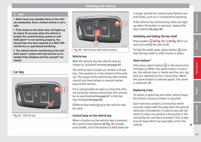
Opening and closing
Note
● Never leave any valuable items in the vehi-cle unattended. Even a locked vehicle is not asafe.
● If the diode on the driver door sill lights upfor about 30 seconds when the vehicle islocked, the central locking system or anti-theft alarm* is not working properly. Youshould have the fault repaired at a SEAT Offi-cial Service or specialised workshop.
● The vehicle interior monitoring of the anti-theft alarm* system will only function as in-tended if the windows and the sunroof* areclosed.
Car key
Fig. 91 Vehicle key
Fig. 92 Vehicle key with alarm button
Vehicle key
With the vehicle key the vehicle may belocked or unlocked remotely ››› page 82.
The vehicle key includes an emitter and bat-tery. The receiver is in the interior of the vehi-cle. The range of the vehicle key with remotecontrol and new battery is several metresaround the vehicle.
If it is not possible to open or close the vehi-cle using the remote control key, this shouldbe re-synchronised ››› page 87 or the bat-tery changed ››› page 86.
Different keys belonging to the vehicle maybe used.
Control lamp on the vehicle key
When a button on the vehicle key is pressed,the control lamp flashes ››› Fig. 91 (arrow)once briefly, but if the button is held down for
a longer period the control lamp flashes sev-eral times, such as in convenience opening.
If the vehicle key control lamp does not lightup when the button is pressed, replace thekey's battery ››› page 86.
Unfolding and folding the key shaft
Press button 1 ››› Fig. 91 or ››› Fig. 92 to un-lock and unfold the key shaft.
To fold the shaft away, press button 1 andfold the key shaft in until it locks in place.
Alarm button*
Only press alarm button 2 in the event of anemergency! When the alarm button is press-ed, the vehicle horn is heard and the turn sig-nals are switched on for a short time. Whenthe alarm button is pressed again, the alarmis switched off.
Replacing a key
To obtain a spare key and other vehicle keys,the vehicle chassis number is required.
Each new key contains a microchip whichmust be coded with the data from the vehicleelectronic immobiliser. A vehicle key will notwork if it does not contain a microchip or themicrochip has not been encoded. This is alsotrue for keys which are specially cut for thevehicle. »
83
Tech
nical
spec
ificati
ons
Adv
ice
Ope
rati
onS
afet
yTh
e es
sent
ials

Operation
The vehicle keys or new spare keys can beobtained from a SEAT Official Service, a spe-cialised workshop or an approved key servicequalified to create this kind of key.
New keys or spare keys must be synchron-ised before use ››› page 87.
CAUTION
All of the vehicle keys contain electronic com-ponents. Protect them from damage, impactsand humidity.
Note
● Only use the key button when you requirethe corresponding function. Pushing the but-ton unnecessarily could accidentally unlockthe vehicle or trigger the alarm. It is also pos-sible even when you are outside the radius ofaction.
● Key operation can be greatly influenced byoverlapping radio signals close to the vehicleworking in the same range of frequencies, forexample, radio transmitters or mobile tele-phones.
● Obstacles between the remote control andthe vehicle, bad weather conditions and dis-charged batteries can considerably reducethe range of the remote control.
● If the buttons of the vehicle key are press-ed ››› Fig. 91 or ››› Fig. 92 or one of the centrallocking buttons ››› page 85 is pressed re-peatedly in short succession, the centrallocking briefly disconnects as protection
against overloading. The vehicle is then un-locked. Lock it if necessary.
Remote unlock/lock
Read the additional information carefully››› page 9
The vehicle will be locked again automatical-ly if you do not open one of the doors or therear lid within 30 seconds after unlocking thecar. This function prevents the vehicle fromremaining unlocked if the unlocking button ispressed by mistake. This does not apply ifyou press the button for at least one sec-ond.
In vehicles with a security central lockingfeature (selective unlocking of side doors)››› page 84, when the button is pressedonce, only the driver door and the fuel tankflap are unlocked. When the button is press-ed a second time, all the vehicle doors areunlocked.
WARNING
Observe the safety warnings ››› in Descrip-tion on page 82.
Note
● Do not use the remote control key until thevehicle is visible.
● Other functions of the remote control key››› page 91, Convenience opening/closing.
Selective unlocking system
The selective unlocking system allows you toonly unlock the driver door and the fuel tankflap. All other doors and the rear lid remainlocked.
Unlocking the driver door and tank flap
– Press button on the remote control keyonce, or turn the key once to open.
Unlocking all the doors, the rear lid and thetank flap simultaneously.
– Within 5 seconds, press button on theremote control key twice, or turn the key toopen twice within 5 seconds.
The anti-theft security system* and the anti-theft alarm* are immediately disabled if youunlock only the driver door, without unlock-ing the other doors.
In vehicles with Easy Connect*, you can pro-gramme the security central locking systemdirectly ››› page 85.
84
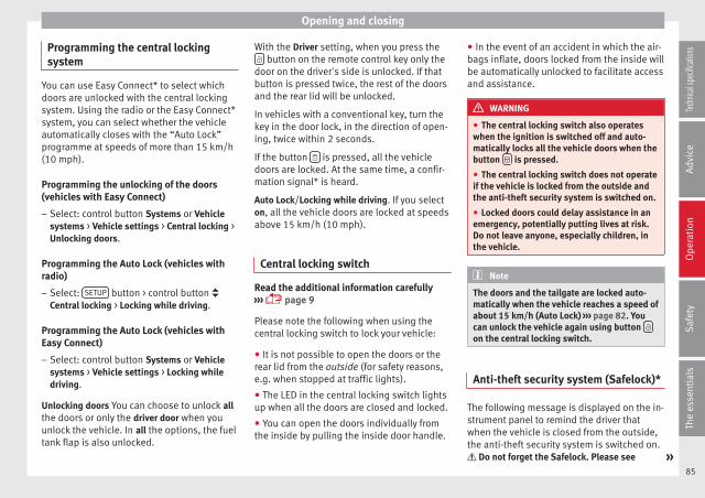
Opening and closing
Programming the central lockingsystem
You can use Easy Connect* to select whichdoors are unlocked with the central lockingsystem. Using the radio or the Easy Connect*system, you can select whether the vehicleautomatically closes with the “Auto Lock”programme at speeds of more than 15 km/h(10 mph).
Programming the unlocking of the doors(vehicles with Easy Connect)
– Select: control button Systems or Vehiclesystems > Vehicle settings > Central locking >Unlocking doors.
Programming the Auto Lock (vehicles withradio)
– Select: SETUP button > control button Central locking > Locking while driving.
Programming the Auto Lock (vehicles withEasy Connect)
– Select: control button Systems or Vehiclesystems > Vehicle settings > Locking whiledriving.
Unlocking doors You can choose to unlock allthe doors or only the driver door when youunlock the vehicle. In all the options, the fueltank flap is also unlocked.
With the Driver setting, when you press the button on the remote control key only the
door on the driver's side is unlocked. If thatbutton is pressed twice, the rest of the doorsand the rear lid will be unlocked.
In vehicles with a conventional key, turn thekey in the door lock, in the direction of open-ing, twice within 2 seconds.
If the button is pressed, all the vehicledoors are locked. At the same time, a confir-mation signal* is heard.
Auto Lock/Locking while driving. If you selecton, all the vehicle doors are locked at speedsabove 15 km/h (10 mph).
Central locking switch
Read the additional information carefully››› page 9
Please note the following when using thecentral locking switch to lock your vehicle:
● It is not possible to open the doors or therear lid from the outside (for safety reasons,e.g. when stopped at traffic lights).
● The LED in the central locking switch lightsup when all the doors are closed and locked.
● You can open the doors individually fromthe inside by pulling the inside door handle.
● In the event of an accident in which the air-bags inflate, doors locked from the inside willbe automatically unlocked to facilitate accessand assistance.
WARNING
● The central locking switch also operateswhen the ignition is switched off and auto-matically locks all the vehicle doors when thebutton is pressed.
● The central locking switch does not operateif the vehicle is locked from the outside andthe anti-theft security system is switched on.
● Locked doors could delay assistance in anemergency, potentially putting lives at risk.Do not leave anyone, especially children, inthe vehicle.
Note
The doors and the tailgate are locked auto-matically when the vehicle reaches a speed ofabout 15 km/h (Auto Lock) ››› page 82. Youcan unlock the vehicle again using button on the central locking switch.
Anti-theft security system (Safelock)*
The following message is displayed on the in-strument panel to remind the driver thatwhen the vehicle is closed from the outside,the anti-theft security system is switched on. Do not forget the Safelock. Please see »
85
Tech
nical
spec
ificati
ons
Adv
ice
Ope
rati
onS
afet
yTh
e es
sent
ials

Operation
Instruction Manual. The vehicle cannot beopened from inside. This makes it more diffi-cult for unauthorised persons to break intothe vehicle ››› in Description on page 82.
The anti-theft security system can be switch-ed off each time the vehicle is locked:
● Turn the key a second time to the lock posi-tion, in the door lock, for the next two sec-onds. If necessary, remove the protective cov-er on the driver door handle ››› page 227 orelse
● Press on the remote control key for asecond time for the following 2 seconds.
The flashing frequency of the diode in thedoor sill immediately confirms the process.Initially, the diode flashes in a fast sequencefor a brief period, then it stops for approxi-mately 30 seconds and, lastly continuesflashing slowly.
Changing the battery
Fig. 93 Vehicle key: opening the battery com-partment
Fig. 94 Vehicle key: removing the battery
SEAT recommends you ask a specialisedworkshop to replace the battery.
The battery is located to the rear of the vehi-cle key, under a cover.
Changing the battery
● Unfold the vehicle key shaft ››› page 83.
● Remove the cover from the back of the ve-hicle key ››› Fig. 93 in the direction of the ar-row ››› .
● Extract the battery from the compartmentusing a suitable thin object ››› Fig. 94.
● Place the new battery in the compartmentas shown ››› Fig. 94, pressing in the oppositedirection to that shown by the arrow ››› .
● Fit the cover as shown ››› Fig. 93, pressingit onto the vehicle key casing in the oppositedirection to that shown by the arrow until itclicks into place.
CAUTION
● If the battery is not changed correctly, thevehicle key may be damaged.
● Use of unsuitable batteries may damagethe vehicle key. For this reason, always re-place the dead battery with another of thesame voltage, size and specifications.
● When fitting the battery, check that the po-larity is correct.
For the sake of the environment
Please dispose of your used batteries correct-ly and with respect for the environment.
86
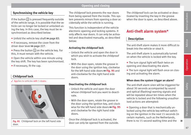
Opening and closing
Synchronising the vehicle key
If the button is pressed frequently outsideof the vehicle range, it is possible that the ve-hicle can no longer be locked or unlocked us-ing the key. In this case, the key must be re-synchronised as described below:
● Unfold the vehicle key shaft ››› page 83.
● If necessary, remove the cover from thedriver door lever ››› page 227.
● Press the button on the vehicle key. Forthis, it must remain with the vehicle.
● Open the vehicle within one minute usingthe key shift. The key has been synchronised.
● If necessary, fit the cap.
Childproof lock3 Applies to vehicles with 5 doors:
Fig. 95 Childproof lock on the left hand sidedoor.
The childproof lock prevents the rear doorsfrom being opened from the inside. This sys-tem prevents minors from opening a door ac-cidentally while the vehicle is running.
This function is independent of the vehicleelectronic opening and locking systems. Itonly affects rear doors. It can only be activa-ted and deactivated manually, as describedbelow:
Activating the childproof lock
– Unlock the vehicle and open the door inwhich you wish to activate the childprooflock.
– With the door open, rotate the groove inthe door using the ignition key, clockwisefor the left hand side doors ››› Fig. 95 andanti-clockwise for the right hand sidedoors.
Deactivating the childproof lock
– Unlock the vehicle and open the doorwhose childproof lock you want to deacti-vate.
– With the door open, rotate the groove inthe door using the ignition key, anti-clock-wise for the left hand side doors ››› Fig. 95and clockwise for the right hand sidedoors.
Once the childproof lock is activated, thedoor can only be opened from the outside.
The childproof lock can be activated or deac-tivated by inserting the key in the groovewhen the door is open, as described above.
Anti-theft alarm system*
Description
The anti-theft alarm makes it more difficult tobreak into the vehicle or steal it.
The anti-theft alarm is automatically turnedon when the vehicle is locked with the key.
● The turn signal light will flash twice onopening and deactivating the alarm.
● The turn signal light will flash once on clos-ing and activating the alarm.
When does the system trigger an alarm?
The anti-theft alarm siren will be triggered forabout 30 seconds accompanied by soundand optical (flashing) warning signals andwill be repeated about ten times when thevehicle is locked and the following unauthor-ised actions are attempted:
● Opening a door that is mechanically un-locked using the vehicle key without switch-ing on the ignition in the next 15 seconds (incertain markets, such as the Netherlands,there is no 15 second waiting time and the »
87
Tech
nical
spec
ificati
ons
Adv
ice
Ope
rati
onS
afet
yTh
e es
sent
ials
Operation
alarm is activated immediately on openingthe door).
● A door is opened.
● The bonnet is opened.
● The rear lid is opened.
● When the ignition is switched on with anon-authorised key.
● When the vehicle battery is disconnected.
● Movement inside the vehicle (in vehicleswith interior monitoring ››› page 89).
● When the vehicle is towed (in vehicles withanti-tow system ››› page 89).
● When the vehicle is raised (in vehicles withanti-tow system ››› page 89).
● When the vehicle is transported on a ferryor by rail (vehicles with an anti-tow system orvehicle interior monitoring ››› page 89).
● When a trailer connected to the anti-theftalarm system is disconnected.
How to turn OFF the alarm
Unlock the vehicle with the unlocking buttonon the key or turn on the ignition with a validkey.
Note
● After 28 days, the indicator light will beswitched off to prevent the battery from ex-hausting if the vehicle has been left parked
for a long period of time. The alarm systemremains activated.
● If, after the audible warning goes off, an-other monitored area is accessed (e.g. therear lid is opened after a door has beenopened), the alarm is triggered again.
● The anti-theft alarm is not activated whenthe vehicle is locked from within using thecentral locking button .
● If the driver door is unlocked mechanicallywith the key, only the driver door is unlocked,the rest of the doors remain locked. Onlywhen the ignition has been turned on will theother doors be available - but not unlocked -and the central lock button will be activated.
● If the vehicle battery is run down or flatthen the anti-theft alarm will not operate cor-rectly.
● Vehicle monitoring remains active even ifthe battery is disconnected or not working forany reason.
● The alarm is triggered immediately if one ofthe battery cables is disconnected while thealarm system is active.
Vehicle interior monitoring and anti-tow system*
It is a monitoring or control function incorpo-rated in the anti-theft alarm* which detectsunauthorized vehicle entry by means of ultra-sound.
Activation
– It is automatically switched on when theanti-theft alarm is activated.
Deactivation
– Open the vehicle with the key, either me-chanically or by pressing the button onthe remote control. The time period fromwhen the door is opened until the key is in-serted in the contact should not exceed 15seconds, otherwise the alarm will be trig-gered.
– Press the button on the remote controltwice. The volumetric sensor and tilt sen-sors will be deactivated. The alarm systemremains activated.
The vehicle interior monitoring and the anti-tow system are automatically switched onagain next time the vehicle is locked.
The vehicle interior monitoring and anti-towsensor (tilt sensor) are automatically switch-ed on when the anti-theft alarm is switchedon. In order to activate it, all the doors andthe rear lid must be closed.
If you wish to switch off the vehicle interiormonitoring and the anti-tow system, it mustbe done each time that the vehicle is locked;if not, they will be automatically switched on.
The vehicle interior monitoring and the anti-tow system should be switched off if animalsare left inside the locked vehicle (otherwise,
88

Opening and closing
their movements will trigger the alarm) orwhen, for example, the vehicle is transportedor has to be towed with only one axle on theground.
False alarms
Interior monitoring will only operate correctlyif the vehicle is completely closed. Please ob-serve related legal requirements.
The following cases may cause a false alarm:
● Open windows (partially or fully).
● Panoramic/tilting sunroof open (partially orcompletely).
● Movement of objects inside the vehicle,such as loose papers, items hanging fromthe rear vision mirror (air fresheners), etc.
Note
● If the vehicle is relocked and the alarm isactivated without the volumetric sensor func-tion, relocking will activate the alarm with allits functions, except the volumetric sensor.This function is reactivated when the alarm isswitched on again, unless it is deliberatelyswitched off.
● If the alarm has been triggered by the volu-metric sensor, this will be indicated by aflashing of the warning lamp on the driverdoor when the vehicle is opened. The flash isdifferent to the flash indicating the alarm isactivated.
● The vibration of a mobile phone left insidethe vehicle may cause the vehicle interiormonitoring alarm to trigger, as both sensorsreact to movements and shakes inside the ve-hicle.
● If on activating the alarm, any door or therear lid is open, only the alarm will be activa-ted. The vehicle interior monitoring and theanti-tow system will only be activated onceall the doors are closed (including the rearlid).
Deactivating the vehicle interiormonitoring and tow-away protection*
Fig. 96 Vehicle interior monitoring/tow-awayprotection button.
When the vehicle is locked, the alarm will betriggered if movements are detected in theinterior (e.g. by animals) or if the vehicle's in-clination is changed (e.g. during transport).You can prevent the alarm from being trig-
gered accidentally by switching off the vehi-cle interior monitoring and/or tow-away pro-tection.
– To switch off the vehicle interior monitoringand tow-away protection, switch off the ig-nition and press button ››› Fig. 96. The indi-cator on the button will light up.
– When the vehicle is locked now, the vehicleinterior monitoring and the tow-away pro-tection are switched off until the next timethe door is opened.
If the anti-theft security system (Safelock)*››› page 85 is switched off, the vehicle interiormonitoring and the tow-away protection areautomatically switched off.
WARNING
Observe the safety warnings ››› in Descrip-tion on page 82.
Rear lid (luggagecompartment)
Rear lid
Read the additional information carefully››› page 9
The rear lid opening system operates electri-cally. It is activated by using the handle onthe boot lid. »
89
Tech
nical
spec
ificati
ons
Adv
ice
Ope
rati
onS
afet
yTh
e es
sent
ials
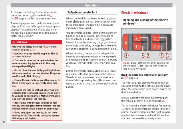
Operation
To change the locking / unlocking status,press the button or the button 1
››› page 9 on the remote control key.
A warning appears on the instrument paneldisplay if the rear lid is open or not properlyclosed.* An audible warning is also given ifthe rear lid is open when the car is drivenfaster than 6 km/h*.
WARNING
Observe the safety warnings ››› in Intro-duction on page 227.
● Always close the rear lid properly. Risk ofaccident or injury.
● The rear lid must not be opened when thereverse or rear fog lights are lit. This maydamage the tail lights.
● Do not close the rear lid by pushing it downwith your hand on the rear window. The glasscould smash. Risk of injury!
● Ensure the rear lid is locked after closing it.If not, it may open unexpectedly while driv-ing.
● Closing the rear lid without observing andensuring it is clear could cause serious injuryto you and to third parties. Make sure that noone is in the path of the rear lid.
● Never drive with the rear lid open or half-closed, exhaust gases may penetrate into theinterior of the vehicle. Danger of poisoning!
● If you only open the rear lid, do not leavethe key inside. The vehicle cannot be openedif the key is left inside.
Tailgate automatic lock
Where the vehicle has been locked by press-ing the button on the remote control withthe rear lid open, the rear lid will lock auto-matically when closed.
The automatic tailgate locking time extensionfunction can be activated. Where this func-tion is activated and once the rear lid hasbeen unlocked by pressing the button onthe remote control key ››› page 84, the rear lidcan be re-opened for a certain length of time.
Where required, the automatic tailgate lock-ing time extension function can be activatedor deactivated at an Authorised SEAT Service,which will provide all the necessary informa-tion.
Before the vehicle locks automatically, thereis a risk of intruders getting into the vehicle.Therefore, we recommend you always lockthe vehicle by pressing the button on theremote control or by using the central lockingbutton.
Electric windows
Opening and closing of the electricwindows*
Fig. 97 Detail of the driver door: controls forthe windows (5-door vehicle with front andrear electric windows).
Read the additional information carefully››› page 10
The front and rear electric windows can beoperated by using the controls on the driverdoor. The other doors each have a switch fortheir own window.
Always close the windows fully if you parkthe vehicle or leave it unattended ››› .
You can use the electric windows for approx.10 minutes after switching off the ignition ifneither the driver door nor the front passen-ger door has been opened and the key hasnot been removed from the ignition.
90
Opening and closing
Safety switch * (only in 5-door vehicles)
Safety switch 5 on the driver door can beused to disable the electric window buttonsin the rear doors.
Safety switch not pressed: buttons on reardoors are activated.
Safety switch pressed: buttons on rear doorsare deactivated.
The safety control symbol lights up in yel-low if the buttons on the rear door are switch-ed off.
WARNING
Observe the safety warnings ››› in Intro-duction on page 227.
● Incorrect use of the electric windows canresult in injury.
● Never close the rear lid without observingand ensuring it is clear, to do otherwise couldcause serious injury to you and third parties.Make sure that no one is in the path of a win-dow.
● The engine may accidentally be started andbe out of control.
● If the ignition is switched on, the electricequipment could be activated with risk of in-jury, for example, in the electric windows.
● The doors can be locked using the remotecontrol key. This could become an obstaclefor assistance in an emergency situation.
● Always take the key with you when youleave the vehicle.
● The electric windows will work until the ig-nition has been switched off and one of thefront doors has been opened.
● If necessary, use the safety switch to disa-ble the rear electric windows. Make sure thatthey have been disabled.
Note
If the window is not able to close because itis stiff or because of an obstruction, the win-dow will automatically open again››› page 91. If this happens, check why thewindow could not be closed before attempt-ing to close it again.
Roll-back function
The roll-back function reduces the risk of in-jury when the electric windows close.
● If a window is obstructed when closing au-tomatically, the window stops at this pointand lowers immediately ››› .
● Next, check why the window does not closebefore attempting it again.
● If you try within the following 10 secondsand the window closes again with difficultyor there is an obstruction, the automatic clos-ing will stop working for 10 seconds.
● If the window is still obstructed, the win-dow will stop at this point.
● If there is no obvious reason why the win-dow cannot be closed, try to close it again bypulling the tab within ten seconds. The win-dow closes with maximum force. The roll-back function is now deactivated.
● If more than 10 seconds pass, the windowwill open fully when you operate one of thebuttons. One-touch closing is reactivated.
WARNING
Observe the safety warnings ››› in Openingand closing of the electric windows* onpage 91.
● The roll-back function does not prevent fin-gers or other parts of the body gettingpinched against the window frame. Risk ofaccident.
Convenience opening/closing
Use the convenience opening/closing func-tion to easily open/close all the windows andthe sliding/tilting sunroof* from the outside.
Convenience open function
– Press and hold button on the remotecontrol key until all the windows and thesliding/tilting sunroof* have reached thedesired position, or »
91
Tech
nical
spec
ificati
ons
Adv
ice
Ope
rati
onS
afet
yTh
e es
sent
ials
Operation
– First unlock the vehicle using button onthe remote control key and then keep thekey in the driver door lock until all the win-dows and the sliding/tilting sunroof* havereached the required position.
Convenience close function
– Press and hold button on the remotecontrol key until all the windows and thesliding/tilting sunroof* are closed ››› , or
– Keep the key in the driver door in the "lock"position until all the windows and the slid-ing/tilting sunroof* are closed.
Programming convenience opening in theEasy Connect*
– Select: function button CAR > control but-ton Vehicle systems* > Car settings > Centrallocking > Open the window by holding buttondown or else > Front window on/off or elseRoof on/off*.
WARNING
● Take care when closing the sliding/tiltingsunroof* and windows. There is a risk of suf-fering injury.
● For safety reasons, you should only use theremote control open and close functions with-in about 2 metres of the vehicle. To avoid in-juries, always keep an eye on the windowsand the sliding/tilting sunroof* when press-ing the button to close them. The windows
stop moving as soon as the button is re-leased.
One-touch opening and closing*
One-touch opening and closing means youdo not have to hold down the button.
Buttons ››› Fig. 97 1 , 2 , 3 and 4 havetwo positions for opening windows and twofor closing them. This makes it easier to openand close windows to the desired position.
One-touch closing
– Pull up the window button briefly up to thesecond position. The window closes fully.
One-touch opening
– Push down the window button briefly up tothe second position. The window opensfully.
Restoring one-touch opening and closing
The automatic open and close function willnot work if the battery has been temporarilydisconnected. The function can be restoredas follows:
– Close the window as far as it will go by lift-ing and holding the electric window switch.
– Release the switch and then lift it again for1 second. This will re-enable the automaticfunction.
If you push (or pull) a button to the firststage, the window will open (or close) untilyou release the button. If you push or lift thebutton briefly to the second stage, the win-dow will open (one-touch opening) or close(one-touch closing) automatically. If you op-erate the button while the window is openingor closing, it stops at this position.
Panoramic sliding sunroof*
Opening or closing the panoramicsliding sunroof
Read the additional information carefully››› page 11
The panoramic sliding sunroof will only workwith the ignition on. It can be opened orclosed for a few minutes after the ignitionhas been switched off, provided the driverdoor and the front passenger door are notopened.
WARNING
Careless or uncontrolled use of the panoram-ic sliding sunroof can cause serious injuries.
92
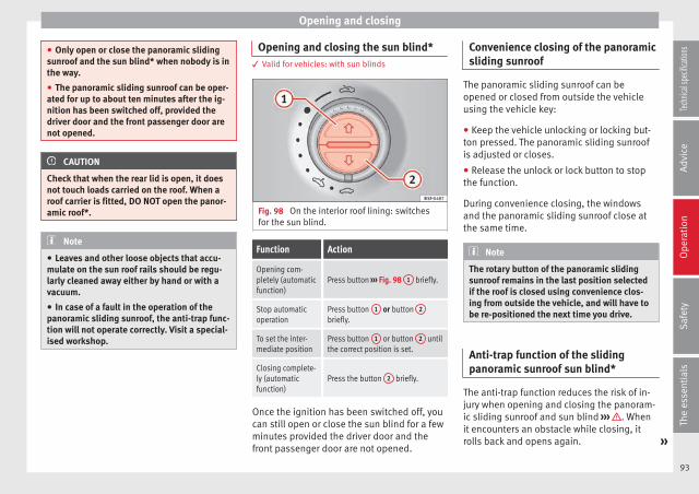
Opening and closing
● Only open or close the panoramic slidingsunroof and the sun blind* when nobody is inthe way.
● The panoramic sliding sunroof can be oper-ated for up to about ten minutes after the ig-nition has been switched off, provided thedriver door and the front passenger door arenot opened.
CAUTION
Check that when the rear lid is open, it doesnot touch loads carried on the roof. When aroof carrier is fitted, DO NOT open the panor-amic roof*.
Note
● Leaves and other loose objects that accu-mulate on the sun roof rails should be regu-larly cleaned away either by hand or with avacuum.
● In case of a fault in the operation of thepanoramic sliding sunroof, the anti-trap func-tion will not operate correctly. Visit a special-ised workshop.
Opening and closing the sun blind*3 Valid for vehicles: with sun blinds
Fig. 98 On the interior roof lining: switchesfor the sun blind.
Function Action
Opening com-pletely (automaticfunction)
Press button ››› Fig. 98 1 briefly.
Stop automaticoperation
Press button 1 or button 2
briefly.
To set the inter-mediate position
Press button 1 or button 2 untilthe correct position is set.
Closing complete-ly (automaticfunction)
Press the button 2 briefly.
Once the ignition has been switched off, youcan still open or close the sun blind for a fewminutes provided the driver door and thefront passenger door are not opened.
Convenience closing of the panoramicsliding sunroof
The panoramic sliding sunroof can beopened or closed from outside the vehicleusing the vehicle key:
● Keep the vehicle unlocking or locking but-ton pressed. The panoramic sliding sunroofis adjusted or closes.
● Release the unlock or lock button to stopthe function.
During convenience closing, the windowsand the panoramic sliding sunroof close atthe same time.
Note
The rotary button of the panoramic slidingsunroof remains in the last position selectedif the roof is closed using convenience clos-ing from outside the vehicle, and will have tobe re-positioned the next time you drive.
Anti-trap function of the slidingpanoramic sunroof sun blind*
The anti-trap function reduces the risk of in-jury when opening and closing the panoram-ic sliding sunroof and sun blind ››› . Whenit encounters an obstacle while closing, itrolls back and opens again. »
93
Tech
nical
spec
ificati
ons
Adv
ice
Ope
rati
onS
afet
yTh
e es
sent
ials
Operation
● Check why the panoramic sliding sunroofor the sun blind does not close.
● Try and close them again.
● If the panoramic sliding sunroof or sunblind is still obstructed, it will stop at the cor-responding position. Close it without the an-ti-trap function.
Closing without the roll-back function
● The switch should be in the “closed posi-tion” ››› page 11 1 .
● Panoramic sliding sunroof: Within five sec-onds of triggering the anti-trap function, pullthe control all the way back ››› page 11(arrow 5 ) until the panoramic sliding sun-roof closes fully.
● Sun blind: Within five seconds of triggeringthe anti-trap function, press button ››› Fig. 98
2 until the sun blind closes fully.
● The panoramic sliding sunroof and sunblind close without the anti-trap function.
● If the panoramic sliding sunroof still cannotbe closed, visit a specialised workshop.
WARNING
Closing the panoramic sliding sunroof or sunblind without the anti-trap function can causeserious injuries.
● Always close the panoramic sliding sunroofcarefully.
● Nobody should be in the way of the panor-amic sliding sunroof or sun blind, especiallywhen they are closed without the anti-trapfunction.
● The anti-trap function does not prevent fin-gers or other parts of the body gettingpinched against the window frame and caus-ing injury.
Note
The anti-trap function is activated if the win-dows and the panoramic sliding sunroof areclosed from the outside of the vehicle usingthe ignition key for convenience closing››› page 91.
Lights and visibility
Lights
Side light and dipped beam headlight
Read the additional information carefully››› page 15
The legal requirements regarding the use ofvehicle lights in each country must be ob-served.
The driver is personally responsible for thecorrect use and adjustment of the lights in allsituations.
Audible warnings to advise the driver thatthe lights have not been switched off
If the key is not in the ignition and the driverdoor is open, an audible warning signal isheard in the following cases: this is a remind-er to turn off the lights.
● When the parking light is on ››› page 95.
● When the light switch is in position or.
WARNING
The side lights or daytime driving lights arenot bright enough to illuminate the roadahead and to ensure that other road users areable to see you.
94

Lights and visibility
● Always use your dipped beam head lights ifit is raining or if visibility is poor.
WARNING
If the headlights are set too high and notused correctly, there is a risk of dazzling ordistracting other road users. This could resultin a serious accident.
● Always make sure that the headlights arecorrectly adjusted.
Daytime driving light
The daytime driving lights consist of individu-al lights, integrated in the front headlights.With the daylight driving lights on, only theselights switch on ››› .
The daytime driving lights switch on everytime the ignition is switched on, if the switchis in positions or , according to the levelof exterior lighting.
When the light switch is in position , alight sensor automatically switches dippedbeam on and off (including the control andinstrument lighting) or the daytime drivinglights depending on the level of exteriorlighting.
WARNING
● Never drive with daytime lights if the roadis not well lit due to weather or lighting con-ditions. Daytime lights do not provideenough light to illuminate the road properlyor be seen by other road users.
● The rear lights do not come on with thedaytime driving light. A vehicle which doesnot have the rear lights on may not be visibleto other drivers in the darkness, in the caseof heavy rain or in conditions of poor visibili-ty.
Turn signal and main beam lever
Read the additional information carefully››› page 15
Push the lever all the way down to turn offthe corresponding function.
Convenience turn signals
For the convenience turn signals, move thelever as far as possible upwards or down-wards and release the lever. The turn signalwill flash three times.
The convenience turn signals are activatedand deactivated in the Easy Connect systemvia the key and the Setup function button››› page 81.
In vehicles that do not have the correspond-ing menu, this function can be deactivated ina specialised workshop.
WARNING
Improper or lack of use of the turn signals, orforgetting to deactivate them can confuseother road users. This could result in a seri-ous accident.
● Always give warning when you are going tochange lane, overtake or when turning, acti-vating the turn signal in good time.
● As soon as you have finished changinglane, overtaking or turning, switch the turnsignal off.
WARNING
Incorrect use of the headlights may cause ac-cidents and serious injury, as the main beammay distract or dazzle other drivers.
Note
● The turn signal only works when the igni-tion is switched on. The hazard warninglights also work when the ignition is switch-ed off.
● If a trailer turn signal malfunctions, thecontrol lamp will stop flashing (trailer turnsignals) and the vehicle turn signal will flashat double speed.
● The main beam headlights can only beswitched on if the dipped beam headlightsare already on. »
95
Tech
nical
spec
ificati
ons
Adv
ice
Ope
rati
onS
afet
yTh
e es
sent
ials

Operation
Note
In cold or damp weather conditions, theheadlights, tail lights and turn signals maymist up inside temporarily. This is normal andin no way effects the useful life of the vehiclelighting system.
Automatic dipped beam control
The automatic dipped beam control is merelyintended as an aid and is not able to recog-nise all driving situations.
When the light switch is in position , thevehicle lights and the instrument panel andswitch lighting switch on and off automatical-ly in the following situations ››› in Daytimedriving light on page 95:
Automatic switchingon
Automatic switchingoff
The photo sensor detectsdarkness, for example,when driving through atunnel.
When adequate lighting isdetected.
The rain sensor detectsrain and activates thewindscreen wipers.
When the windscreen wip-ers have been inactive fora few minutes.
WARNING
If the road is not well lit and other road userscannot see the vehicle well enough or at all,accidents may occur.
● The automatic dipped beam control ()only switches on the dipped beam whenthere are no changes in brightness, and not,for example when it is foggy.
Main beam assist*
Main beam assist (Light Assist)
The main beam assist operates, within thelimits of the system and depending on theenvironmental and traffic conditions, as of aspeed of 60 km/h (37 mph) when it switcheson automatically, and is then deactivatedagain below 30 km/h (18 mph) ››› . This ismanaged via a camera situated on the baseof the interior mirror.
The main beam assist generally detects illu-minated areas and deactivates the mainbeam when passing through a town, for ex-ample.
Switching the main beam assist on and off
Func-tion
Action
Acti-vate:
– Switch the ignition on and turn the lightswitch to position .– From the base position, move the mainbeam and turn signal lever forwards››› page 95. When the warning lamp is dis-played on the instrument panel display, themain beam assist is switched on.
Toswitchsystem
off:
– Switch off the ignition.– OR: turn the light switch to a different posi-tion to ››› page 94.– OR: with main beam on, move the mainbeam and turn signal lever backwards.– OR: move the main beam and turn the sig-nal lever forwards to manually switch themain beam on. The main beam assist will thenbe deactivated.
Malfunctions
The following conditions may prevent themain beam headlight control from turning offthe headlights in time or from turning off al-together:
● In poorly lit towns with highly reflectivesigns.
● Other insufficiently lit road users (such aspedestrians or cyclists).
● On tight bends and steep slopes (bumps)and when oncoming vehicles are partially ob-scured.
96
Lights and visibility
● When the drivers of other oncoming vehi-cles (such as a truck) can see over a guardrail in the centre of the road.
● If the camera is damaged or the power sup-ply is cut off.
● In fog, snow and heavy rain.
● With dust and sand turbulence.
● With loose gravel in the field of vision ofthe camera.
● When the field of vision of the camera ismisted up, dirty or covered by stickers, snow,ice, etc.
WARNING
The convenience features of the main beamassist should not encourage the taking ofrisks. The system is not a replacement fordriver concentration.
● You are always in control of the main beamand adapting it to the light, visibility and traf-fic conditions.
● It is possible that the main beam headlightcontrol does not recognise all driving situa-tions and is limited under certain circumstan-ces.
● When the field of vision of the camera isdirty, covered or damaged, operation of themain beam control may be affected. This alsoapplies when changes are made to the vehi-
cle lighting system, for example, if additionalheadlights are installed.
CAUTION
To avoid affecting the operation of the sys-tem, take the following points into considera-tion:
● Clean the field of vision of the camera regu-larly and make sure it is free of snow and ice.
● Do not cover the field of vision of the cam-era.
● Check that the windscreen is not damagedin the area of the field of vision of the camera.
Note
Main beam and headlight flasher can beturned on and off manually at any time withthe turn signal and main beam lever››› page 95.
Fog lights
The warning lamps or also show, on thelight switch or instrument panel, when thefog lights are on.
● Switching on front fog lights* : pull thelight switch to the first point 1 , from posi-tions , or .
● Switching on the rear fog light : com-pletely pull the light switch 2 from position, or .
● To switch off the fog lights, press the lightswitch or turn it to position .
Cornering lights*1)
When turning slowly or on very tight bends,the cornering lights are activated automati-cally. The cornering lights may be integratedin the fog lights and are switched on only atspeeds of less than 40 km/h (25 mph).
When reverse gear is engaged, the corneringlights on both sides of the vehicle switch on,in order to better illuminate the area for park-ing.
Coming home “function”
This function may be connected/disconnec-ted through the radio menu. The “ComingHome” and/or “Leaving Home” delay timemay also be set (default: 30 sec). »
1) This function is not available on vehicles equippedwith full-LED headlights.
97
Tech
nical
spec
ificati
ons
Adv
ice
Ope
rati
onS
afet
yTh
e es
sent
ials

Operation
Vehicle withhalogenheadlights
In the “Coming Home” function, the day-time running lights (DRL), the rear sidelights and the licence plate lights areturned on.
Vehicle withfull-LEDheadlights
In the “Coming Home” function, the dip-ped beams and the daytime runninglights (DRL), the rear side lights and thelicence plate lights are switched on.
Automatic* activation of “Coming Home”
For vehicles with a light and rain sensor (rota-ry light switch in position ).
● Switch off the engine and remove the keyfrom the ignition with the rotary light switchin position ››› page 15.
● The automatic “Coming Home” function isonly active when the light sensor detectsdarkness.
● When the car door is opened, the “ComingHome” lighting comes on.
Manual “Coming Home” activation
For vehicles with a light and rain sensor (rota-ry light switch without position ).
● Switch off the engine and remove the keyfrom the ignition.
● Activate the headlight flashers for approxi-mately 1 second.
● Activated for any position of the rotary lightswitch.
● When the car door is opened, the “ComingHome” lighting comes on. The headlights areturned off 60 seconds after the vehicle dooris opened.
Deactivation
● If no door has been closed, they go out au-tomatically after 60 seconds.
● After the last door has been closed, theheadlights will be switched off after the“Coming Home” delay (as established in theradio menu) has elapsed.
● On turning the light switch to position ››› page 15.
● When the ignition is switched on (whenstarting the engine).
“Leaving Home” function
The “Leaving Home” function is only availa-ble for vehicles with a light and rain sensor(rotary light switch in position ).
This function may be connected/disconnec-ted through the radio menu. The “LeavingHome” function switch-off delay may also beset (default: 30 sec).
Vehicle withhalogenheadlights
In the “Leaving Home” function, the day-time running lights (DRL), the rear sidelights and the licence plate lights areswitched on.
Vehicle withfull-LEDheadlights
In the “Leaving Home” function, the dip-ped beams, the daytime running lights(DRL), the rear side lights and the li-cence plate lights are switched on.
Activation
● When the vehicle is unlocked using the re-mote control.
● The “Leaving Home” function is only activa-ted when the rotary light switch is in position and the light sensor detects darkness.
Deactivation
● When the “Leaving Home” delay periodends (default: 30 sec).
● When the vehicle is locked using the re-mote control.
● When the light control is switched into aposition other than .
● With the ignition is switched on.
98
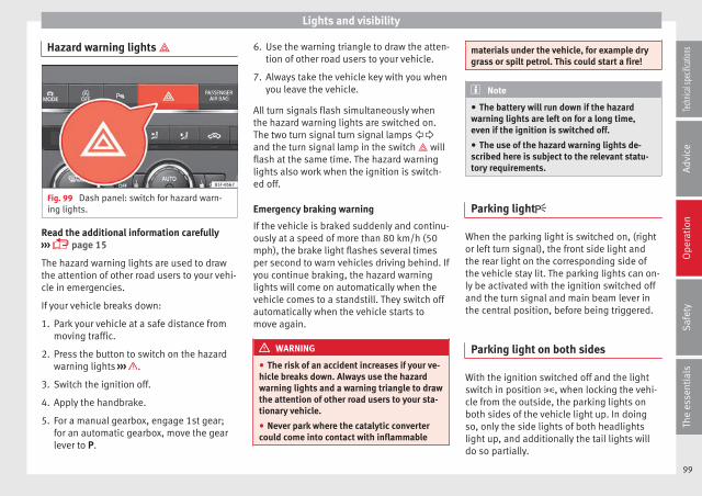
Lights and visibility
Hazard warning lights
Fig. 99 Dash panel: switch for hazard warn-ing lights.
Read the additional information carefully››› page 15
The hazard warning lights are used to drawthe attention of other road users to your vehi-cle in emergencies.
If your vehicle breaks down:
1. Park your vehicle at a safe distance frommoving traffic.
2. Press the button to switch on the hazardwarning lights ››› .
3. Switch the ignition off.
4. Apply the handbrake.
5. For a manual gearbox, engage 1st gear;for an automatic gearbox, move the gearlever to P.
6. Use the warning triangle to draw the atten-tion of other road users to your vehicle.
7. Always take the vehicle key with you whenyou leave the vehicle.
All turn signals flash simultaneously whenthe hazard warning lights are switched on.The two turn signal turn signal lamps and the turn signal lamp in the switch willflash at the same time. The hazard warninglights also work when the ignition is switch-ed off.
Emergency braking warning
If the vehicle is braked suddenly and continu-ously at a speed of more than 80 km/h (50mph), the brake light flashes several timesper second to warn vehicles driving behind. Ifyou continue braking, the hazard warninglights will come on automatically when thevehicle comes to a standstill. They switch offautomatically when the vehicle starts tomove again.
WARNING
● The risk of an accident increases if your ve-hicle breaks down. Always use the hazardwarning lights and a warning triangle to drawthe attention of other road users to your sta-tionary vehicle.
● Never park where the catalytic convertercould come into contact with inflammable
materials under the vehicle, for example drygrass or spilt petrol. This could start a fire!
Note
● The battery will run down if the hazardwarning lights are left on for a long time,even if the ignition is switched off.
● The use of the hazard warning lights de-scribed here is subject to the relevant statu-tory requirements.
Parking light
When the parking light is switched on, (rightor left turn signal), the front side light andthe rear light on the corresponding side ofthe vehicle stay lit. The parking lights can on-ly be activated with the ignition switched offand the turn signal and main beam lever inthe central position, before being triggered.
Parking light on both sides
With the ignition switched off and the lightswitch in position , when locking the vehi-cle from the outside, the parking lights onboth sides of the vehicle light up. In doingso, only the side lights of both headlightslight up, and additionally the tail lights willdo so partially.
99
Tech
nical
spec
ificati
ons
Adv
ice
Ope
rati
onS
afet
yTh
e es
sent
ials
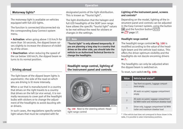
Operation
Motorway lights*
The motorway light is available on vehiclesequipped with full-LED lights.
The function is connected/disconnected viathe corresponding Easy Connect systemmenu.
● Activation: when going above 110 km/h formore than 30 seconds, the dipped beam rai-ses slightly to increase the distance of visibil-ity of the driver.
● Deactivation: when reducing the speed ofthe car below 100 km/h, the dipped beam re-turns to its normal position.
Driving abroad
The light beam of the dipped beam lights isasymmetric: the side of the road on whichyou are driving is lit more intensely.
When a car that is manufactured in a countrythat drives on the right travels to a countrythat drives on the left (or vice versa), it is nor-mally necessary to cover part of the headlightbulbs with stickers or to change the adjust-ment of the headlights to avoid dazzling oth-er drivers.
In such cases, the regulations specify certainlight values that must be complied with for
designated points of the light distribution.This is known as “Tourist light”.
The light distribution that the halogen andfull-LED headlights of the SEAT Leon rangehave allows the specific “tourist light” valuesto be met without the need for stickers orchanges in the settings.
Note
“Tourist light” is only allowed temporarily. Ifyou are planning a long stay in a country thatdrives on the other side, you should take thevehicle to an Authorised Technical Service tochange the headlights.
Headlight range control, lighting ofthe instrument panel and controls
Fig. 100 Next to the steering wheel: Head-light range control
Lighting of the instrument panel, screensand controls*
Depending on the model, lighting of the in-strument panel and controls can be adjustedin the Easy Connect system, using the button and the function button SETUP
››› page 17.
Headlight range control
The headlight range control ››› Fig. 100 ismodified according to the value of the head-light beam and the vehicle load status. Thisoffers the driver optimum visibility and theheadlights do not dazzle oncoming drivers››› .
The headlights can only be adjusted whenthe dipped beam is switched on.
To reset, turn switch ››› Fig. 100:
Value Vehicle load statusa)
–Two front occupants, luggage compart-ment empty
1All seats occupied, luggage compartmentempty
2All seats occupied, luggage compartmentfull With trailer and minimum drawbar load
3Driver only, luggage compartment full Withtrailer and maximum drawbar load
a) If the vehicle load does not correspond to those shown in thetable, it is possible to select intermediary positions.
100
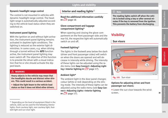
Lights and visibility
Dynamic headlight range control
The control is not mounted in vehicles withdynamic headlight range control. The head-light range is automatically adjusted accord-ing to the vehicle load status when they areswitched on.
Instrument panel lighting
With the ignition on and without light activa-tion, the instrument panel lighting remainsactivated in daytime light conditions. Thelighting is reduced as the exterior light di-minishes. In some cases, e.g. when drivingthrough a tunnel without the functionactive, the instrument panel lighting mayeven switch off. The objective of this functionis to provide the driver with a visual indica-tion that he or she should activate the dip-ped beam.
WARNING
Heavy objects in the vehicle may mean thatthe headlights dazzle and distract other driv-ers. This could result in a serious accident.
● Adjust the light beam to the vehicle loadstatus so that it does not blind other drivers.
Interior and reading lights1)
Read the additional information carefully››› page 16
Glove compartment and luggagecompartment lighting*
When opening and closing the glove com-partment on the front passenger side and therear lid, the respective light will automaticallyswitch on and off.
Footwell lighting*
The lights in the footwell area below the dash(driver and front passenger sides) will switchon when the doors are opened and will de-crease in intensity while driving. The intensityof these lights can be adjusted using the ra-dio menu (see Easy Connect > Adjusting Light-ing > Interior lighting ››› page 17).
Ambient light*
The ambient light in the door panel changescolour (white or red) depending on the driv-ing mode. The intensity of these lights can beadjusted using the radio menu (see Easy Con-nect > Adjusting Lights > Interior lighting››› page 17).
Note
The reading lights switch off when the vehi-cle is locked using a key or after several mi-nutes if the key is removed from the ignition.This prevents the battery from discharging.
Visibility
Sun visors
Fig. 101 Sun visor
Options for adjusting driver and frontpassenger sun visors:
● Lower the sun visor towards the wind-screen. »
1) Depending on the level of equipment fitted in thevehicle, LEDs can be used for the following interiorlights: front courtesy light, rear courtesy light, foot-well light and sun visor light.
101
Tech
nical
spec
ificati
ons
Adv
ice
Ope
rati
onS
afet
yTh
e es
sent
ials
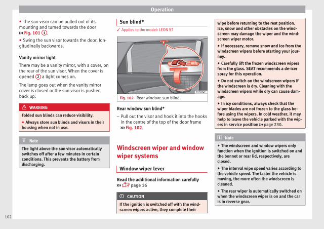
Operation
● The sun visor can be pulled out of itsmounting and turned towards the door››› Fig. 101 1 .
● Swing the sun visor towards the door, lon-gitudinally backwards.
Vanity mirror light
There may be a vanity mirror, with a cover, onthe rear of the sun visor. When the cover isopened 2 a light comes on.
The lamp goes out when the vanity mirrorcover is closed or the sun visor is pushedback up.
WARNING
Folded sun blinds can reduce visibility.
● Always store sun blinds and visors in theirhousing when not in use.
Note
The light above the sun visor automaticallyswitches off after a few minutes in certainconditions. This prevents the battery fromdischarging.
Sun blind*3 Applies to the model: LEON ST
Fig. 102 Rear window: sun blind.
Rear window sun blind*
– Pull out the visor and hook it into the hooksin the centre of the top of the door frame››› Fig. 102.
Windscreen wiper and windowwiper systems
Window wiper lever
Read the additional information carefully››› page 16
CAUTION
If the ignition is switched off with the wind-screen wipers active, they complete their
wipe before returning to the rest position.Ice, snow and other obstacles on the wind-screen may damage the wiper and the wind-screen wiper motor.
● If necessary, remove snow and ice from thewindscreen wipers before starting your jour-ney.
● Carefully lift the frozen windscreen wipersfrom the glass. SEAT recommends a de-icerspray for this operation.
● Do not switch on the windscreen wipers ifthe windscreen is dry. Cleaning with thewindscreen wipers while dry can cause dam-age.
● In icy conditions, always check that thewiper blades are not frozen to the glass be-fore using the wipers. In cold weather, it mayhelp to leave the vehicle parked with the wip-ers in service position ››› page 230.
Note
● The windscreen and window wipers onlyfunction when the ignition is switched on andthe bonnet or rear lid, respectively, areclosed.
● The interval wipe speed varies according tothe vehicle speed. The faster the vehicle ismoving, the more often the windscreen iscleaned.
● The rear wiper is automatically switched onwhen the windscreen wiper is on and the caris in reverse gear.
102
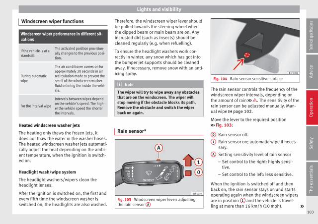
Lights and visibility
Windscreen wiper functions
Windscreen wiper performance in different sit-uations
If the vehicle is at astandstill
The activated position provision-ally changes to the previous posi-tion.
During automaticwipe
The air conditioner comes on forapproximately 30 seconds in airrecirculation mode to prevent thesmell of the windscreen washerfluid entering the inside the vehi-cle.
For the interval wipe
Intervals between wipes dependon the vehicle's speed. The high-er the vehicle speed the shorterthe intervals.
Heated windscreen washer jets
The heating only thaws the frozen jets, itdoes not thaw the water in the washer hoses.The heated windscreen washer jets automati-cally adjust the heat depending on the ambi-ent temperature, when the ignition is switch-ed on.
Headlight wash/wipe system
The headlight washers/wipers clean theheadlight lenses.
After the ignition is switched on, the first andevery fifth time the windscreen washer isswitched on, the headlights are also washed.
Therefore, the windscreen wiper lever shouldbe pulled towards the steering wheel whenthe dipped beam or main beam are on. Anyincrusted dirt (such as insects) should becleaned regularly (e.g. when refuelling).
To ensure the headlight washers work cor-rectly in winter, any snow which has got intothe bumper jet supports should be cleanedaway. If necessary, remove snow with an anti-icing spray.
Note
The wiper will try to wipe away any obstaclesthat are on the windscreen. The wiper willstop moving if the obstacle blocks its path.Remove the obstacle and switch the wiperback on again.
Rain sensor*
Fig. 103 Windscreen wiper lever: adjustingthe rain sensor A
Fig. 104 Rain sensor sensitive surface
The rain sensor controls the frequency of thewindscreen wiper intervals, depending onthe amount of rain ››› . The sensitivity of therain sensor can be adjusted manually. Man-ual wipe ››› page 102.
Move the lever to the required position››› Fig. 103:
Rain sensor off.
Rain sensor on; automatic wipe if neces-sary.
Setting sensitivity level of rain sensor
– Set control to the right: highly sensi-tive.
– Set control to the left: less sensitive.
When the ignition is switched off and thenback on, the rain sensor stays on and startsoperating again when the windscreen wipersare in position 1 and the vehicle is travel-ling at more than 16 km/h (10 mph). »
0
1
A
103
Tech
nical
spec
ificati
ons
Adv
ice
Ope
rati
onS
afet
yTh
e es
sent
ials
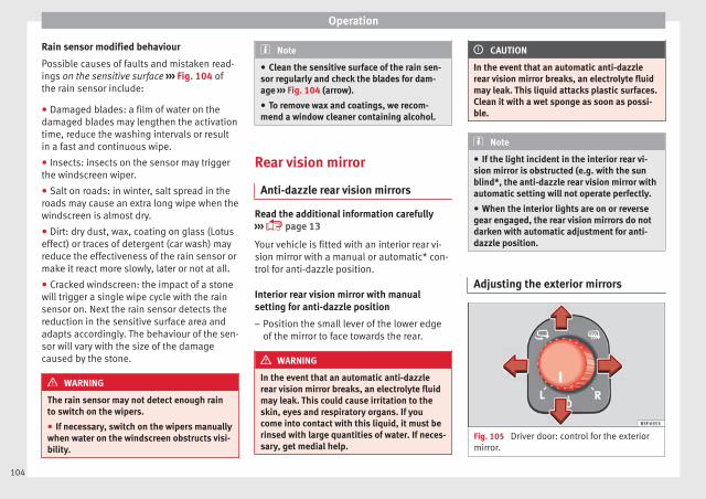
Operation
Rain sensor modified behaviour
Possible causes of faults and mistaken read-ings on the sensitive surface ››› Fig. 104 ofthe rain sensor include:
● Damaged blades: a film of water on thedamaged blades may lengthen the activationtime, reduce the washing intervals or resultin a fast and continuous wipe.
● Insects: insects on the sensor may triggerthe windscreen wiper.
● Salt on roads: in winter, salt spread in theroads may cause an extra long wipe when thewindscreen is almost dry.
● Dirt: dry dust, wax, coating on glass (Lotuseffect) or traces of detergent (car wash) mayreduce the effectiveness of the rain sensor ormake it react more slowly, later or not at all.
● Cracked windscreen: the impact of a stonewill trigger a single wipe cycle with the rainsensor on. Next the rain sensor detects thereduction in the sensitive surface area andadapts accordingly. The behaviour of the sen-sor will vary with the size of the damagecaused by the stone.
WARNING
The rain sensor may not detect enough rainto switch on the wipers.
● If necessary, switch on the wipers manuallywhen water on the windscreen obstructs visi-bility.
Note
● Clean the sensitive surface of the rain sen-sor regularly and check the blades for dam-age ››› Fig. 104 (arrow).
● To remove wax and coatings, we recom-mend a window cleaner containing alcohol.
Rear vision mirror
Anti-dazzle rear vision mirrors
Read the additional information carefully››› page 13
Your vehicle is fitted with an interior rear vi-sion mirror with a manual or automatic* con-trol for anti-dazzle position.
Interior rear vision mirror with manualsetting for anti-dazzle position
– Position the small lever of the lower edgeof the mirror to face towards the rear.
WARNING
In the event that an automatic anti-dazzlerear vision mirror breaks, an electrolyte fluidmay leak. This could cause irritation to theskin, eyes and respiratory organs. If youcome into contact with this liquid, it must berinsed with large quantities of water. If neces-sary, get medial help.
CAUTION
In the event that an automatic anti-dazzlerear vision mirror breaks, an electrolyte fluidmay leak. This liquid attacks plastic surfaces.Clean it with a wet sponge as soon as possi-ble.
Note
● If the light incident in the interior rear vi-sion mirror is obstructed (e.g. with the sunblind*, the anti-dazzle rear vision mirror withautomatic setting will not operate perfectly.
● When the interior lights are on or reversegear engaged, the rear vision mirrors do notdarken with automatic adjustment for anti-dazzle position.
Adjusting the exterior mirrors
Fig. 105 Driver door: control for the exteriormirror.
104
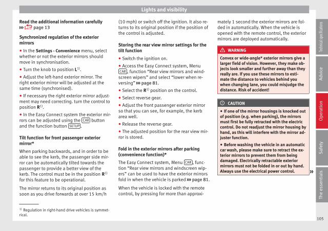
Lights and visibility
Read the additional information carefully››› page 13
Synchronized regulation of the exteriormirrors
● In the Settings - Convenience menu, selectwhether or not the exterior mirrors shouldmove in synchronisation.
● Turn the knob to position L1).
● Adjust the left-hand exterior mirror. Theright exterior mirror will be adjusted at thesame time (synchronised).
● If necessary the right exterior mirror adjust-ment may need correcting. turn the control toposition R1).
● In the Easy Connect system the exterior mir-rors can be adjusted using the CAR buttonand the function button SETUP .
Tilt function for front passenger exteriormirror*
When parking backwards, and in order to beable to see the kerb, the passenger side mir-ror can be automatically tilted towards thepassenger to provide a better view of thekerb. The control must be in the position R1)
for this feature to be operational.
The mirror returns to its original position assoon as you drive forwards at over 15 km/h
(10 mph) or switch off the ignition. It also re-turns to its original position if the position ofthe control is adjusted.
Storing the rear view mirror settings for thetilt function
● Switch the ignition on.
● Access the Easy Connect system, MenuCAR , function “Rear view mirrors and wind-
screen wipers” and select “lower when re-versing” ››› page 81.
● Select the R1) position on the control.
● Select reverse gear.
● Adjust the front passenger exterior mirrorso that you can see, for example, the kerbarea well.
● Release the reverse gear.
● The adjusted position for the rear view mir-ror is stored.
Fold in the exterior mirrors after parking(convenience function)*
The Easy Connect system, Menu CAR , func-tion “Rear view mirrors and windscreen wip-ers” can be used to have the exterior mirrorsfold in when the vehicle is parked ››› page 81.
When the vehicle is locked with the remotecontrol, by pressing for more than approxi-
mately 1 second the exterior mirrors are fol-ded in automatically. When the vehicle isopened with the remote control, the exteriormirrors are deployed automatically.
WARNING
Convex or wide-angle* exterior mirrors give alarger field of vision. However, they make ob-jects look smaller and further away than theyreally are. If you use these mirrors to esti-mate the distance to vehicles behind youwhen changing lane, you could misjudge thedistance. Risk of accident!
CAUTION
● If one of the mirror housings is knocked outof position (e.g. when parking), the mirrorsmust first be fully retracted with the electriccontrol. Do not readjust the mirror housing byhand, as this will interfere with the mirror ad-juster function.
● Before washing the vehicle in an automaticcar wash, please make sure to retract the ex-terior mirrors to prevent them from beingdamaged. Electrically retractable exteriormirrors must not be folded in or out by hand.Always use the electrical power control. »
1) Regulation in right-hand drive vehicles is symmet-rical.
105
Tech
nical
spec
ificati
ons
Adv
ice
Ope
rati
onS
afet
yTh
e es
sent
ials
Operation
Note
If the electrical adjustment should fail to op-erate, both of the mirrors can be adjusted byhand by lightly pressing the edge of the mir-ror glass.
Seats and head restraints
Adjusting the seats andheadrests
Manual adjustment of seats
Read the additional information carefully››› page 12
WARNING
The safe driving chapter contains importantinformation, tips, suggestions and warningsthat you should read and observe for yourown safety and the safety of your passengers››› page 37.
WARNING
● Adjust the front seats only when the vehi-cle is stationary. Failure to follow this instruc-tion could result in an accident.
● Be careful when adjusting the seat height.Careless or uncontrolled adjustment cancause injuries.
● The front seat backrests must not be re-clined for driving. Otherwise, seat belts andthe airbag system might not protect as theyshould, with the subsequent danger of injury.
Electric driver seat adjustment*
Read the additional information carefully››› page 12
WARNING
● If the electric front seats are used negli-gently or without paying due attention, it cancause serious injury.
● The front seats can also be electrically ad-justed when the ignition is switched off. Nev-er leave a child or any other person who mayneed help in the vehicle.
● In the event of an emergency, electrical ad-justment can be stopped by pressing anycontrol.
CAUTION
To avoid damaging the electrical componentsof the front seats, please refrain from kneel-ing on the seat or applying sharp pressure ata single point to the seat cushion and back-rest.
Note
● It may not be possible to electrically adjustthe seat if the vehicle battery is very low.
● If the engine is started while the seats arebeing electrically adjusted, the adjustmentwill stop.
106
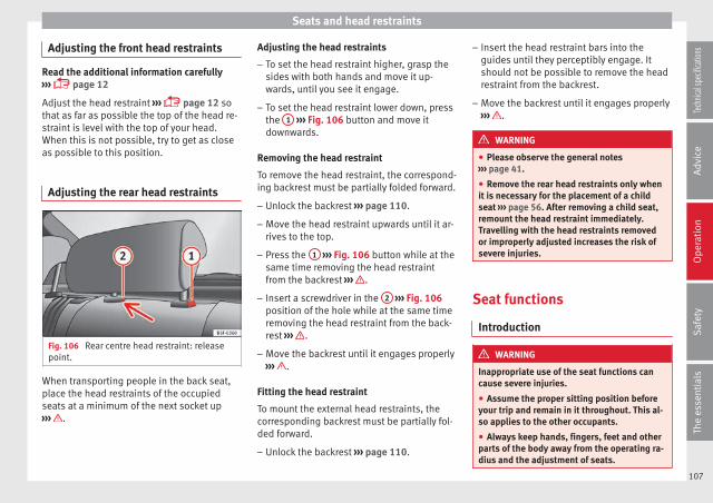
Seats and head restraints
Adjusting the front head restraints
Read the additional information carefully››› page 12
Adjust the head restraint ››› page 12 sothat as far as possible the top of the head re-straint is level with the top of your head.When this is not possible, try to get as closeas possible to this position.
Adjusting the rear head restraints
Fig. 106 Rear centre head restraint: releasepoint.
When transporting people in the back seat,place the head restraints of the occupiedseats at a minimum of the next socket up››› .
Adjusting the head restraints
– To set the head restraint higher, grasp thesides with both hands and move it up-wards, until you see it engage.
– To set the head restraint lower down, pressthe 1 ››› Fig. 106 button and move itdownwards.
Removing the head restraint
To remove the head restraint, the correspond-ing backrest must be partially folded forward.
– Unlock the backrest ››› page 110.
– Move the head restraint upwards until it ar-rives to the top.
– Press the 1 ››› Fig. 106 button while at thesame time removing the head restraintfrom the backrest ››› .
– Insert a screwdriver in the 2 ››› Fig. 106position of the hole while at the same timeremoving the head restraint from the back-rest ››› .
– Move the backrest until it engages properly››› .
Fitting the head restraint
To mount the external head restraints, thecorresponding backrest must be partially fol-ded forward.
– Unlock the backrest ››› page 110.
– Insert the head restraint bars into theguides until they perceptibly engage. Itshould not be possible to remove the headrestraint from the backrest.
– Move the backrest until it engages properly››› .
WARNING
● Please observe the general notes››› page 41.
● Remove the rear head restraints only whenit is necessary for the placement of a childseat ››› page 56. After removing a child seat,remount the head restraint immediately.Travelling with the head restraints removedor improperly adjusted increases the risk ofsevere injuries.
Seat functions
Introduction
WARNING
Inappropriate use of the seat functions cancause severe injuries.
● Assume the proper sitting position beforeyour trip and remain in it throughout. This al-so applies to the other occupants.
● Always keep hands, fingers, feet and otherparts of the body away from the operating ra-dius and the adjustment of seats.
107
Tech
nical
spec
ificati
ons
Adv
ice
Ope
rati
onS
afet
yTh
e es
sent
ials

Operation
Seat heating
Fig. 107 In the centre console: front seatsheating switch
The seat cushions can be heated electricallywhen the ignition is switched on. The back-rest is also heated in some versions.
The seat heating should not be engaged inany of the following conditions:
● The seat is unoccupied.
● The seat has a covering.
● There is a child seat installed in the seat.
● The seat cushion is wet or damp.
● The indoor or outdoor temperature is great-er than 25°C (77°F).
Activate
Press the button or . Seat heating isswitched on fully.
Adjusting the heating output
Press the button or repeatedly until thedesired intensity level is reached.
Deactivating
Press the button or until all warninglamps switch off.
WARNING
People who, because of medications, paraly-sis or chronic diseases (e.g. diabetes) cannotperceive pain or temperature, or have a limi-ted perception thereof, may suffer burns tothe back, buttocks or legs when using seatheating, an occurrence that may entail a verylengthy recovery period or from which it maynot be possible to recover fully. Seek medicaladvice if you have doubts regarding yourhealth.
● People with limited pain and temperaturethresholds must never use seat heating.
WARNING
If the fabric of the cushion is wet, this can ad-versely affect the operation of the seat heat-ing, increasing the risk of burns.
● Make sure the seat cushion is dry prior tousing the seat heater.
● Do not sit on the seat with clothing that iswet or damp.
● Do not leave clothing that is wet or dampon the seat.
● Do not spill liquid on the seat.
CAUTION
● To avoid damaging the heating elements ofthe seat heaters, please do not kneel on theseat or apply sharp pressure to a single pointon the seat cushion or backrest.
● Liquids, sharps objects and insulating ma-terials (e.g. covers or child seats) can damagethe seat heating.
● In the event of smells, switch off the seatheating immediately and have it inspected bya specialised workshop.
For the sake of the environment
The seat heating should remain on only whenneeded. Otherwise, it is an unnecessary fuelwaste.
Front centre armrest
The centre armrest can be adjusted to variouslevels.
Adjusting the centre armrest
– To adjust the tilt, lift the armrest from thestarting position so that it is engaged.
– To return the armrest to the starting posi-tion, remove the armrest from the upperfixed position and lower it.
108
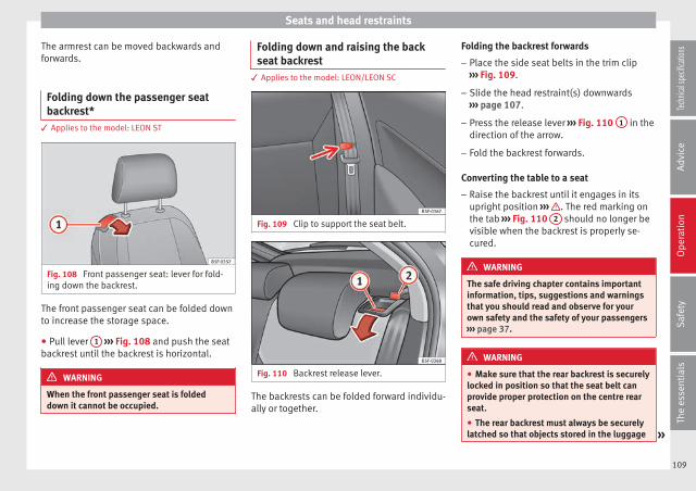
Seats and head restraints
The armrest can be moved backwards andforwards.
Folding down the passenger seatbackrest*
3 Applies to the model: LEON ST
Fig. 108 Front passenger seat: lever for fold-ing down the backrest.
The front passenger seat can be folded downto increase the storage space.
● Pull lever 1 ››› Fig. 108 and push the seatbackrest until the backrest is horizontal.
WARNING
When the front passenger seat is foldeddown it cannot be occupied.
Folding down and raising the backseat backrest
3 Applies to the model: LEON/LEON SC
Fig. 109 Clip to support the seat belt.
Fig. 110 Backrest release lever.
The backrests can be folded forward individu-ally or together.
Folding the backrest forwards
– Place the side seat belts in the trim clip››› Fig. 109.
– Slide the head restraint(s) downwards››› page 107.
– Press the release lever ››› Fig. 110 1 in thedirection of the arrow.
– Fold the backrest forwards.
Converting the table to a seat
– Raise the backrest until it engages in itsupright position ››› . The red marking onthe tab ››› Fig. 110 2 should no longer bevisible when the backrest is properly se-cured.
WARNING
The safe driving chapter contains importantinformation, tips, suggestions and warningsthat you should read and observe for yourown safety and the safety of your passengers››› page 37.
WARNING
● Make sure that the rear backrest is securelylocked in position so that the seat belt canprovide proper protection on the centre rearseat.
● The rear backrest must always be securelylatched so that objects stored in the luggage »
109
Tech
nical
spec
ificati
ons
Adv
ice
Ope
rati
onS
afet
yTh
e es
sent
ials

Operation
compartment will not fly forward through theinterior during sudden braking.
CAUTION
● With the backrest inclined there is a dangerof damaging the rear head restraints whenadjusting the front seats backwards.
● When folding the backrest forwards, makesure to place the side seat belts in the trimclip to prevent them from being damaged bybecoming trapped in the backrest lock.
Folding down and lifting the rear seatbackrest
3 Applies to the model: LEON ST
Fig. 111 On the rear seat backrest: releasecatch 1 ; red mark 2 .
Fig. 112 In the luggage compartment: leversfor remote release of the left part 1 and rightpart 2 of the rear seat backrest.
The rear seat backrest is split and each partbe lowered separately to extend the luggagecompartment.
When the rear seat backrest is lowered no-body else can travel in the correspondingseats (not even a child).
Lowering the rear seat backrest with theunlock button
● Lower the head restraint properly.
● Push the unlock button ››› Fig. 111 1 for-wards and at the same time lift the backrest.
● The rear seat backrest is not engaged whenthe red marking of the button 2 is visible.
Lowering the rear seat backrest with theremote release lever
● Lower the head restraint properly.
● Open the rear lid.
● Pull the remote release lever of the left part››› Fig. 112 1 or right part 2 of the backrestin the direction of the arrow. The releasedpart of the rear seat backrest is folded auto-matically down and forwards.
● If this occurs, close the rear lid.
The rear seat backrest is not engaged whenthe red marking of the button ››› Fig. 111 2
is visible.
Folding up the rear seat backrest
● Lift the backrest and press it firmly into thelock until it engages ››› .
● It should not be possible to see the redmark of the unlock button 2 .
● The backrest must be properly engaged.
WARNING
Serious injuries can be caused if the rear seatbackrest is lowered or lifted without due careand attention.
● Never lower or lift the rear seat backrestwhile driving.
● Do no trap or damage the seat belt whenraising the rear seat backrest.
● When lowering or lifting the rear seat back-rest, keep your hands, fingers, feet and otherbody parts out of its path.
110

Transport and practical equipment
● For the rear seat seat belts to offer the nec-essary protection all the parts of the rearbackrest must be properly engaged. This isparticularly important in the case of the cen-tre rear seat. If someone is seated in a seatwhose backrest is not properly engaged theywill fly forward, along with the backrest, dur-ing an accident or a sudden driving or brakingmanoeuvre.
● A red signal on the button 2 warns thatthe backrest is not engaged. Always checkthat the red marking is not visible when thebackrest is in the upright position.
● When the rear seat backrest is lowered or isnot properly engaged nobody else can travelin the corresponding seats (not even a child).
CAUTION
Serious damage can be caused to the vehicleand other objects if the rear seat backrest islowered or lifted without due care and atten-tion.
● Before lowering the rear seat backrest, al-ways adjust the front seats so that neitherthe head restraints nor the cushions of therear backrest can hit them.
Transport and practicalequipment
Storage compartments
Storage areas under the front seats*
Fig. 113 Storage compartment under thefront seats.
There is a storage compartment with a coverunder each front seat.
The drawer* is opened by pulling on the cov-er ››› Fig. 113.
To close the drawer, press the cover until itlocks into position.
WARNING
● The drawers will hold a maximum weight of1.5 kg.
● Do not drive with the drawer cover open.There is an injury risk for passengers if thecargo is released in case of sudden braking oran accident.
Folding table*3 Applies to the model: LEON ST
Fig. 114 Left-hand front seat: folding table.
– To open the tray, open it up in the directionof the arrow ››› Fig. 114.
WARNING
● The folding trays may not be folded downwhilst the vehicle is in motion and anyone isseated on the second row of seats. There is arisk of injury during a sudden braking ma-noeuvre! The tray must therefore be closedand properly secured whilst the vehicle is inmotion. »
111
Tech
nical
spec
ificati
ons
Adv
ice
Ope
rati
onS
afet
yTh
e es
sent
ials

Operation
● Do not put hot drinks in the drink holders.During normal or sudden driving manoeuvres,sudden braking or an accident, the hot drinkcould be spilled. Danger of scalding.
CAUTION
When driving, do not leave open cans in thecup holders. The drink might be spilt on brak-ing, for example, and could damage the vehi-cle.
Drink holders
Fig. 115 Centre console: front drink holders.
Front drink holders
– Place drinks in the holder ››› Fig. 115.Placement of two drinks is possible. Thereis also the possibility of placing larger plas-tic bottles in the trims of the doors.
WARNING
● Do not place any hot drinks in the drinkholder while the vehicle is moving. Hot drinkscould spill and cause burns, which may causean accident.
● Do not use hard china cups or glasses.These could cause injury in the event of anaccident.
CAUTION
You should avoid putting open drinks con-tainers in the cup holders. The drinks couldotherwise spill over and cause damage to e.g.the electrical equipment or the seat covers.
Glove box
Fig. 116 Glove compartment
Opening/closing
– To open the glove compartment, pull thehandle in the direction of the arrow.
– To close the glove compartment, move thecover upwards until it engages.
Depending on the vehicle equipment, the CDplayer is located in the glove compartment.Separate operating instructions are enclosedfor this equipment in the corresponding In-struction Manual.
WARNING
The cover of the glove compartment shouldalways be closed while driving. Failure to fol-low this instruction could result in an acci-dent.
Other storage compartments
You will find more object holders, compart-ments and supports in other parts of the ve-hicle:
● In the top of the glove compartment in ve-hicles that do not have a CD reader. The loadof the compartment should not exceed1.2 kg.
● In the centre console under the centre arm-rest*.
● In the driver side panel there is a remova-ble box for access to fuses and relays. The
112
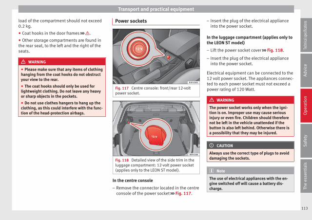
Transport and practical equipment
load of the compartment should not exceed0.2 kg.
● Coat hooks in the door frames ››› .
● Other storage compartments are found inthe rear seat, to the left and the right of theseats.
WARNING
● Please make sure that any items of clothinghanging from the coat hooks do not obstructyour view to the rear.
● The coat hooks should only be used forlightweight clothing. Do not leave any heavyor sharp objects in the pockets.
● Do not use clothes hangers to hang up theclothing, as this could interfere with the func-tion of the head-protection airbags.
Power sockets
Fig. 117 Centre console: front/rear 12-voltpower socket.
Fig. 118 Detailed view of the side trim in theluggage compartment: 12-volt power socket(applies only to the LEON ST model).
In the centre console
– Remove the connector located in the centreconsole of the power socket ››› Fig. 117.
– Insert the plug of the electrical applianceinto the power socket.
In the luggage compartment (applies only tothe LEON ST model)
– Lift the power socket cover ››› Fig. 118.
– Insert the plug of the electrical applianceinto the power socket.
Electrical equipment can be connected to the12 volt power socket. The appliances connec-ted to each power socket must not exceed apower rating of 120 Watt.
WARNING
The power socket works only when the igni-tion is on. Improper use may cause seriousinjury or even fire. Children should thereforenot be left in the vehicle unattended if thebutton is also left behind. Otherwise there isa possibility that they may be injured.
CAUTION
Always use the correct type of plugs to avoiddamaging the sockets.
Note
The use of electrical appliances with the en-gine switched off will cause a battery dis-charge.
113
Tech
nical
spec
ificati
ons
Adv
ice
Ope
rati
onS
afet
yTh
e es
sent
ials

Operation
Storing objects
Loading the luggage compartment
All luggage and other loose objects must besafely secured in the luggage compartment.Unsecured objects which shift back and forthcould impair the driving safety or drivingcharacteristics of the vehicle by shifting thecentre of gravity.
– Distribute the load evenly in the luggagecompartment.
– Place heavy objects as far forward as possi-ble in the luggage compartment.
– Place the heavy objects first.
– Secure heavy objects to the fitted fasteningrings ››› page 119.
WARNING
● Loose luggage and other objects in the lug-gage compartment could cause serious inju-ries.
● Always stow objects in the luggage com-partment and secure them on the fasteningrings.
● Use suitable straps to secure heavy ob-jects.
● During sudden manoeuvres or accidents,loose objects can be thrown forward, injuringvehicle occupants or passers-by. This in-creased risk of injury will be further increased
if a loose object is struck by an inflating air-bag. If this happens, objects may shoot out-ward like a missile. Risk of fatal injury.
● Please note that the centre of gravity mayshift when transporting heavy objects; thismay affect vehicle handling and lead to an ac-cident. Therefore, it is essential to adjustyour speed and driving style accordingly, toavoid accidents.
● Never exceed the allowed axle weights orallowed maximum weight. If said weights areexceeded, the driving characteristics of thevehicle may change, leading to accidents, in-juries and damage to the vehicle.
● Never leave your vehicle unattended, espe-cially when the rear lid is open. Childrencould climb into the luggage compartment,closing the door behind them; they will betrapped and run the risk of death.
● Never allow children to play in or aroundthe vehicle. Close and lock all the doors andrear lid when you leave the vehicle. Beforeyou lock the vehicle, make sure that there areno adults or children in the vehicle.
Note
● Air circulation in the vehicle helps reducefogging of the windows. Used air escapesthrough ventilation slits in the side trim ofthe luggage compartment. Ensure that theventilation slots are never covered.
● Straps for securing the load to the fasten-ing rings are commercially available.
Luggage compartment cover3 Applies to the model: LEON/LEON SC
Fig. 119 Rear lid open with the luggage com-partment cover.
The luggage compartment cover blocks theview into the luggage compartment.
Removing
– Remove the straps A and unfasten thecover of the support B by pressing up-wards in the direction of arrow 1 .
Fitting
– Insert the cover horizontally so that it coin-cides with the “plate” on the axis of thesupports B and press down until it engag-es.
– Attach the straps to the rear lid A ››› .
114
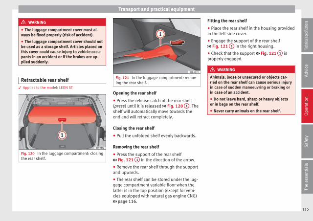
Transport and practical equipment
WARNING
● The luggage compartment cover must al-ways be fixed properly (risk of accident).
● The luggage compartment cover should notbe used as a storage shelf. Articles placed onthis cover could cause injury to vehicle occu-pants in an accident or if the brakes are ap-plied suddenly.
Retractable rear shelf3 Applies to the model: LEON ST
Fig. 120 In the luggage compartment: closingthe rear shelf.
Fig. 121 In the luggage compartment: remov-ing the rear shelf.
Opening the rear shelf
● Press the release catch of the rear shelf(press) until it is released ››› Fig. 120 1 . Theshelf will automatically move towards theend and will retract completely.
Closing the rear shelf
● Pull the unfolded shelf evenly backwards.
Removing the rear shelf
● Press the support of the rear shelf››› Fig. 121 1 in the direction of the arrow.
● Remove the rear shelf through the supportand upwards.
● The rear shelf can be stored under the lug-gage compartment variable floor when thelatter is in the top position (except for vehi-cles equipped with natural gas engine CNG)››› page 116.
Fitting the rear shelf
● Place the rear shelf in the housing providedin the left side cover.
● Engage the support of the rear shelf››› Fig. 121 1 in the right housing.
● Check that the support ››› Fig. 121 1 isproperly engaged.
WARNING
Animals, loose or unsecured or objects car-ried on the rear shelf can cause serious injuryin case of sudden manoeuvring or braking orin case of an accident.
● Do not leave hard, sharp or heavy objectsor in bags on the rear shelf.
● Never carry animals on the rear shelf.
115
Tech
nical
spec
ificati
ons
Adv
ice
Ope
rati
onS
afet
yTh
e es
sent
ials
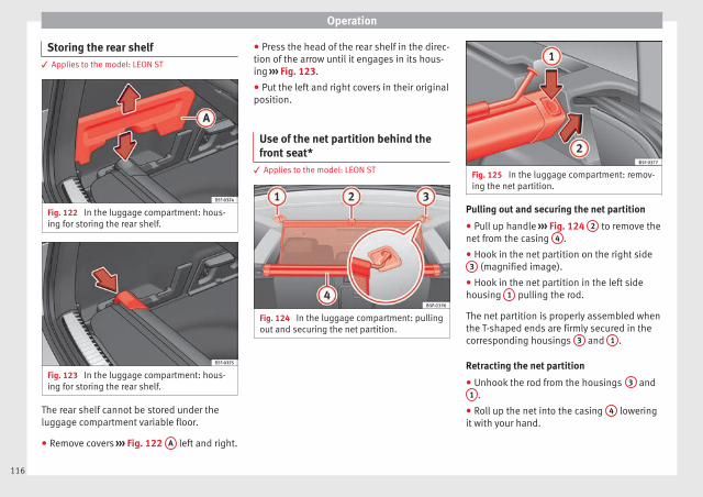
Operation
Storing the rear shelf3 Applies to the model: LEON ST
Fig. 122 In the luggage compartment: hous-ing for storing the rear shelf.
Fig. 123 In the luggage compartment: hous-ing for storing the rear shelf.
The rear shelf cannot be stored under theluggage compartment variable floor.
● Remove covers ››› Fig. 122 A left and right.
● Press the head of the rear shelf in the direc-tion of the arrow until it engages in its hous-ing ››› Fig. 123.
● Put the left and right covers in their originalposition.
Use of the net partition behind thefront seat*
3 Applies to the model: LEON ST
Fig. 124 In the luggage compartment: pullingout and securing the net partition.
Fig. 125 In the luggage compartment: remov-ing the net partition.
Pulling out and securing the net partition
● Pull up handle ››› Fig. 124 2 to remove thenet from the casing 4 .
● Hook in the net partition on the right side3 (magnified image).
● Hook in the net partition in the left sidehousing 1 pulling the rod.
The net partition is properly assembled whenthe T-shaped ends are firmly secured in thecorresponding housings 3 and 1 .
Retracting the net partition
● Unhook the rod from the housings 3 and1 .
● Roll up the net into the casing 4 loweringit with your hand.
116

Transport and practical equipment
Removing the net partition
● Fold the rear seat backrests forward.
● Press the left or right release catch››› Fig. 125 in the direction of the arrow 1 .
● Remove the casing from the support in thedirection of the arrow ››› Fig. 125 2 .
Fitting the net partition
● Fold the rear seat backrests forward.
● Fit the casing in the right and left supports.
● Press the casing into the left and right sup-ports in the opposite direction to the arrow››› Fig. 125 2 until it engages.
The red markings on the release buttonsshould no longer be visible.
WARNING
● Always secure objects, even when the netpartition is properly assembled.
● There should be nobody behind the assem-bled partition when the vehicle is moving.
CAUTION
Incorrect handling of the net partition couldcause damage.
● Do not “release” the net partition whenlowering it, as the net and other vehicle partscould be damaged. Roll down the net parti-tion by hand.
Use of the net partition with the rearseat backrests lowered
3 Applies to the model: LEON ST
Fig. 126 Assembling the net partition in therear seat backrests.
Fig. 127 In the luggage compartment: netpartition hooked into the rear seat backrests.
Fitting the net partition
● Fold the rear seat backrests forward.
● Remove the net partition from the side sup-ports.
● Place the net casing in the rail slots in thedirection of the arrows ››› Fig. 126 1 .
● Push the casing towards the left side of thevehicle in the direction of arrow ››› Fig. 126
2 and as far as it will go.
● Check that the net is secure.
Pulling out and securing the net partition
● Pull up handle ››› Fig. 127 2 to remove thenet from the casing ››› Fig. 127 4 .
● Hook in the net partition on the right side››› Fig. 127 3 (magnified image).
● Hook in the net partition in the left sidehousing ››› Fig. 127 1 pulling the rod.
The net partition is properly assembled whenthe T-shaped ends are firmly secured in thecorresponding housings ››› Fig. 127 3 and
1 .
Retracting the net partition
● Remove the rod from the housings in thetrims of the roof side members.
● Roll up the net into the casing ››› Fig. 1274 lowering it with your hand. »
117
Tech
nical
spec
ificati
ons
Adv
ice
Ope
rati
onS
afet
yTh
e es
sent
ials
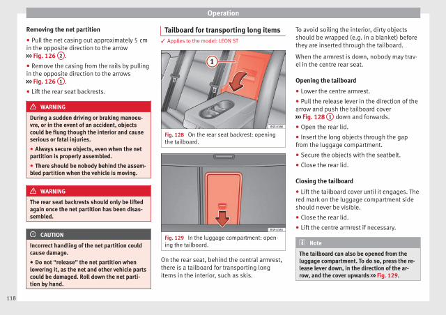
Operation
Removing the net partition
● Pull the net casing out approximately 5 cmin the opposite direction to the arrow››› Fig. 126 2 .
● Remove the casing from the rails by pullingin the opposite direction to the arrows››› Fig. 126 1 .
● Lift the rear seat backrests.
WARNING
During a sudden driving or braking manoeu-vre, or in the event of an accident, objectscould be flung though the interior and causeserious or fatal injuries.
● Always secure objects, even when the netpartition is properly assembled.
● There should be nobody behind the assem-bled partition when the vehicle is moving.
WARNING
The rear seat backrests should only be liftedagain once the net partition has been disas-sembled.
CAUTION
Incorrect handling of the net partition couldcause damage.
● Do not “release” the net partition whenlowering it, as the net and other vehicle partscould be damaged. Roll down the net parti-tion by hand.
Tailboard for transporting long items3 Applies to the model: LEON ST
Fig. 128 On the rear seat backrest: openingthe tailboard.
Fig. 129 In the luggage compartment: open-ing the tailboard.
On the rear seat, behind the central armrest,there is a tailboard for transporting longitems in the interior, such as skis.
To avoid soiling the interior, dirty objectsshould be wrapped (e.g. in a blanket) beforethey are inserted through the tailboard.
When the armrest is down, nobody may trav-el in the centre rear seat.
Opening the tailboard
● Lower the centre armrest.
● Pull the release lever in the direction of thearrow and push the tailboard cover››› Fig. 128 1 down and forwards.
● Open the rear lid.
● Insert the long objects through the gapfrom the luggage compartment.
● Secure the objects with the seatbelt.
● Close the rear lid.
Closing the tailboard
● Lift the tailboard cover until it engages. Thered mark on the luggage compartment sideshould never be visible.
● Close the rear lid.
● Lift the centre armrest if necessary.
Note
The tailboard can also be opened from theluggage compartment. To do so, press the re-lease lever down, in the direction of the ar-row, and the cover upwards ››› Fig. 129.
118

Transport and practical equipment
Fastening rings*
Fig. 130 In the luggage compartment: fasten-ing rings (LEON/LEON SC model except ver-sions with spare wheel and CNG).
Fig. 131 In the luggage compartment: fasten-ing rings (LEON ST model).
In the front and rear part of the luggage com-partment there are fastening rings to securethe luggage ››› Fig. 131.
In order to use the fastening rings, they mustbe lifted beforehand1).
WARNING
If unsuitable or damaged belts or retainingstraps are used, they could break in the eventof braking or an accident. Objects could thenbe launched across the passenger compart-ment and cause serious or fatal injuries.
● Always use belts or retaining straps thatare suitable and in a good condition.
● Belts and retaining straps should be se-curely fastened to the fastening rings.
● Objects in the luggage compartment thatare unsecured could move suddenly and mod-ify the handling of the vehicle.
● Secure all objects, little and large.
● Never exceed the maximum tensile load ofthe fastening ring when securing objects.
● Never secure a child seat to the fasteningrings.
Note
● The maximum tensile load that the fasten-ing rings can support is 3.5 kN.
● Belts and securing systems for the appro-priate load can be obtained from specialiseddealerships. SEAT recommends visiting aSEAT dealership for this.
● The fastening rings are rendered unusablefor versions with spare wheel and CNG.
1) Valid only for the LEON ST model.119
Tech
nical
spec
ificati
ons
Adv
ice
Ope
rati
onS
afet
yTh
e es
sent
ials
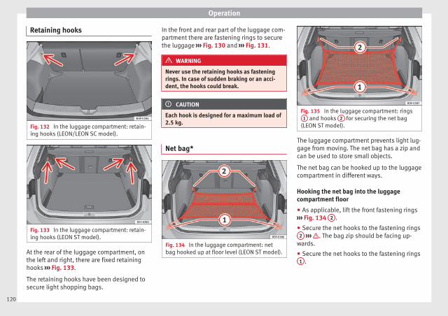
Operation
Retaining hooks
Fig. 132 In the luggage compartment: retain-ing hooks (LEON/LEON SC model).
Fig. 133 In the luggage compartment: retain-ing hooks (LEON ST model).
At the rear of the luggage compartment, onthe left and right, there are fixed retaininghooks ››› Fig. 133.
The retaining hooks have been designed tosecure light shopping bags.
In the front and rear part of the luggage com-partment there are fastening rings to securethe luggage ››› Fig. 130 and ››› Fig. 131.
WARNING
Never use the retaining hooks as fasteningrings. In case of sudden braking or an acci-dent, the hooks could break.
CAUTION
Each hook is designed for a maximum load of2.5 kg.
Net bag*
Fig. 134 In the luggage compartment: netbag hooked up at floor level (LEON ST model).
Fig. 135 In the luggage compartment: rings1 and hooks 2 for securing the net bag
(LEON ST model).
The luggage compartment prevents light lug-gage from moving. The net bag has a zip andcan be used to store small objects.
The net bag can be hooked up to the luggagecompartment in different ways.
Hooking the net bag into the luggagecompartment floor
● As applicable, lift the front fastening rings››› Fig. 134 2 .
● Secure the net hooks to the fastening rings2 ››› . The bag zip should be facing up-
wards.
● Secure the net hooks to the fastening rings1 .
120

Transport and practical equipment
Hook the net bag next to the load threshold
● Secure the short net hooks to the fasteningrings ››› Fig. 135 1 ››› . The bag zip shouldbe facing upwards.
● Secure the straps in the bag hooks 2 .
Removing the net bag
The hooked up net bag is taut ››› .
● Remove the hooks and the net bag strapsfrom the fastening rings and from the baghooks.
● Store the net bag in the luggage compart-ment.
WARNING
To secure the elastic net bag on the fasteningrings it must be stretched out. Once hookedup it is taut. If the net bag is hooked up or un-hooked incorrectly the hooks could cause in-juries.
● Always secure the net hooks properly sothat they do not suddenly release from thefastening rings when hooking or unhookingthem.
● On hooking or unhooking them, protectyour eyes and face in case the hooks are re-leased suddenly.
● Always hook up the net bag hooks in thedescribed order. If a hook is unexpectedly re-leased the risk of injury is increased.
Luggage compartment variable floor3 Applies to the model: LEON ST
Fig. 136 Luggage compartment variablefloor: positions.
Fig. 137 Luggage compartment variablefloor: grooves tilted.
Variable floor in the high position
● Lift the floor using handle ››› Fig. 136 1
and pull it back until the front of the floor hasfully passed the supports 2 .
● Move the floor forward over the supports asfar as the rear seat backrest and then lowerthe floor with the handle 1 .
Variable floor in the low position
● Lift the floor using handle ››› Fig. 136 1
and pull it back until the front of the floor hasfully passed the supports 2 .
● Now match the front part with the lowergrooves of the supports and slide the floorforwards as far as the rear seat backrest andlower the floor at the same time with the han-dle 1 .
Variable floor in the tilted position
When the variable floor is tilted you can ac-cess the spare wheel/anti-puncture kit area.
● Lift the variable floor using handle››› Fig. 136 1 and pull it back until the frontof the floor has fully passed the tiltedgrooves ››› Fig. 137 3 .
● Run the floor through these grooves withthe help of handle 1 as the rear seat back-rest and until the floor is resting in thegrooves.
WARNING
During a sudden driving or braking manoeu-vre, or in the event of an accident, objectscould be flung though the interior and causeserious or fatal injuries. »
121
Tech
nical
spec
ificati
ons
Adv
ice
Ope
rati
onS
afet
yTh
e es
sent
ials

Operation
● Always secure objects, even when the lug-gage compartment floor is properly lifted.
● Only objects that do not protrude morethan 2/3 the height of the floor may be car-ried between the rear seat and the raised lug-gage compartment floor.
● Only objects that do not weigh than ap-proximately 7.5 kg may be carried betweenthe rear seat and the raised luggage compart-ment floor.
CAUTION
● The maximum weight that can be loaded onthe luggage compartment variable floor inthe top position is 150 kg.
● Do not let the luggage compartment floorfall when closing it. Always carefully guide itdownwards in a controlled manner. Other-wise, the lining and the floor of the luggagecompartment could be damaged.
Note
SEAT recommends the use of straps to secureobjects to retaining rings.
Roof carrier
Introduction
The vehicle roof has been designed to opti-mise aerodynamics. For this reason, cross
bars or conventional roof carrier systems can-not be secured to the roof water drains.
As the roof water drains are integrated in theroof to reduce air resistance, only SEAT-ap-proved cross bars and roof carrier systemscan be used.
Cases in which cross bars and the roofcarrier system should be disassembled.
● When they are not used.
● When the vehicle is washed in a car wash.
● When the vehicle height exceeds the maxi-mum height, for example, in some garages.
WARNING
When heavy or bulky loads are transportedon the roof carrier system, car driving per-formance is affected, as the centre of gravityshifts and there is greater wind resistance.
● Always secure the load properly using beltsor retaining straps that are suitable and in agood condition.
● Bulky, heavy, long or flat loads have a neg-ative effect on aerodynamics, the centre ofgravity and driving performance.
● Avoid sudden braking and manoeuvres.
● Adapt your speed and driving style at alltimes to suit visibility, weather, road and traf-fic conditions.
CAUTION
● Remove the cross bars and the roof carriersystem before entering a car wash.
● Vehicle height is increased by the installa-tion of cross bars or a roof carrier system andthe load secured on them. For this purpose,check that your vehicle's height does not sur-pass the headspace limit, for example, for un-derpasses or for entering garage doors.
● Cross bars, a roof carrier system and theload secured on them should not interferewith the roof aerial or hamper the path of thepanoramic sun roof ››› page 92 and the rearlid.
● On opening the rear lid make sure that itdoes not knock into the roof load.
For the sake of the environment
When cross bars and a roof carrier system areinstalled, the increased air resistance meansthat the vehicle uses more fuel.
122
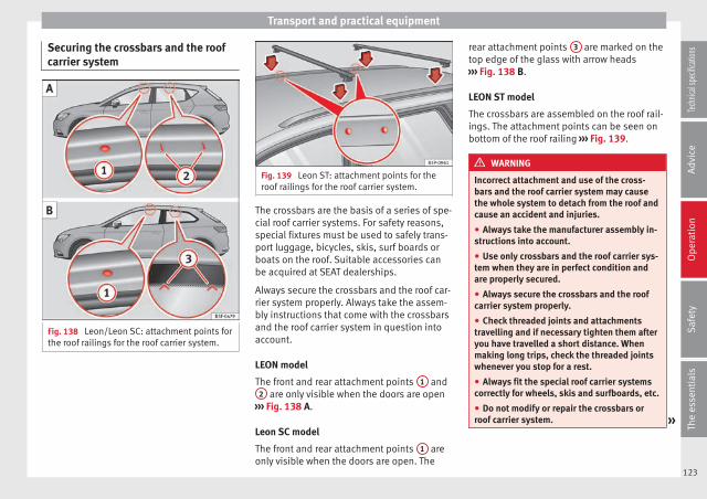
Transport and practical equipment
Securing the crossbars and the roofcarrier system
Fig. 138 Leon/Leon SC: attachment points forthe roof railings for the roof carrier system.
Fig. 139 Leon ST: attachment points for theroof railings for the roof carrier system.
The crossbars are the basis of a series of spe-cial roof carrier systems. For safety reasons,special fixtures must be used to safely trans-port luggage, bicycles, skis, surf boards orboats on the roof. Suitable accessories canbe acquired at SEAT dealerships.
Always secure the crossbars and the roof car-rier system properly. Always take the assem-bly instructions that come with the crossbarsand the roof carrier system in question intoaccount.
LEON model
The front and rear attachment points 1 and2 are only visible when the doors are open
››› Fig. 138 A.
Leon SC model
The front and rear attachment points 1 areonly visible when the doors are open. The
rear attachment points 3 are marked on thetop edge of the glass with arrow heads››› Fig. 138 B.
LEON ST model
The crossbars are assembled on the roof rail-ings. The attachment points can be seen onbottom of the roof railing ››› Fig. 139.
WARNING
Incorrect attachment and use of the cross-bars and the roof carrier system may causethe whole system to detach from the roof andcause an accident and injuries.
● Always take the manufacturer assembly in-structions into account.
● Use only crossbars and the roof carrier sys-tem when they are in perfect condition andare properly secured.
● Always secure the crossbars and the roofcarrier system properly.
● Check threaded joints and attachmentstravelling and if necessary tighten them afteryou have travelled a short distance. Whenmaking long trips, check the threaded jointswhenever you stop for a rest.
● Always fit the special roof carrier systemscorrectly for wheels, skis and surfboards, etc.
● Do not modify or repair the crossbars orroof carrier system. »
123
Tech
nical
spec
ificati
ons
Adv
ice
Ope
rati
onS
afet
yTh
e es
sent
ials
Operation
Note
Always read the assembly instructions thatcome with the crossbars and the roof carriersystem carefully and keep them in the vehi-cle.
Loading the roof carrier system
The load can only be secured if the crossbarsand the roof carrier system are properly in-stalled ››› .
Maximum authorised roof load
The maximum permissible roof load is 75 kg.This figure comes from the combined weightof the roof carrier, the cross bars and the loaditself on the roof ››› .
Always check the weight of the roof carriersystem, the cross bars and the weight of theload to be transported and weigh them ifnecessary. Never exceed the maximum au-thorised roof load.
If you are using cross bars and a roof carrierwith a lower weight rating, you will not beable to carry the maximum authorised roofload. In this case, do not exceed the maxi-mum weight limit for the roof carrier which islisted in the fitting instructions.
Distributing a load
Distribute loads uniformly and secure themcorrectly ››› .
Check attachments
Once the cross bars and roof carrier systemhave been installed, check the bolted con-nections and attachments after a short jour-ney and subsequently with a certain frequen-cy.
WARNING
Exceeding the maximum authorised roof loadcan result in accidents and considerable vehi-cle damage.
● Never exceed the maximum authorisedload on the roof and on the axles or the vehi-cle's maximum authorised weight.
● Never exceed the load capacity of the crossbars and the roof carrier system, even if themaximum authorised roof load has not beenreached.
● Secure heavy items as far forward as possi-ble and distribute the vehicle load uniformly.
WARNING
If the load is loose or not secured, it could fallfrom the roof carrier system or cause acci-dents and injuries.
● Always use belts or retaining straps thatare suitable and in a good condition.
● Secure the load properly.
Air conditioning
Heating, ventilation andcooling
Introduction
Read the additional information carefully››› page 26
Viewing Climatronic information
On the screen of Climatronic control unit andon the screen of the factory-fitted Easy Con-nect system, the theoretical values of thetemperature zones are shown.
The unit of temperature measurement can bechanged in the Easy Connect system.
Dust and pollen filter
The dust and pollen filter with its activatedcharcoal cartridge serves as a barrier againstimpurities in the air taken into the vehicle in-terior.
The dust and pollen filter must be changedregularly so that air conditioner performanceis not adversely affected.
If the filter loses efficiency prematurely dueto use in areas with very high levels of airpollution, the filter must be changed morefrequently than stated in the Service Sched-ule.
124

Air conditioning
WARNING
Reduced visibility through the windows in-creases the risk of serious accidents.
● Always ensure that all windows are free ofice and snow, and that they are not fogged,so as to maintain good visibility of everythingoutside.
● The maximum heat output required to de-frost windows as quickly as possible is onlyavailable when the engine has reached itsnormal running temperature. Only drive whenyou have good visibility.
● Always ensure that you use the heatingsystem, fresh air system, air conditioner andthe heated rear window to maintain good visi-bility to the outside.
● Never leave the air recirculation on for along period of time. If the cooling system isswitched off and air recirculation modeswitched on, the windows can mist over veryquickly, considerably limiting visibility.
● Switch air recirculation mode off when it isnot required.
WARNING
Stuffy or used air will increase fatigue and re-duce driver concentration possibly resultingin a serious accident.
● Never leave the fresh air fan turned off oruse the air recirculation for long periods oftime; the air in the vehicle interior will not berefreshed.
CAUTION
● Switch the air conditioner off if you think itmay be broken. This will avoid additionaldamage. Have the air conditioner checked bya specialised workshop.
● Repairs to the air conditioner require spe-cialist knowledge and special tools. SEAT rec-ommends visiting a SEAT Official Service.
Note
● When the cooling system is turned off, aircoming from the outside will not be dried. Toprevent fogging of the windows, SEAT recom-mends leaving the cooling system (compres-sor) turned on. To do this, press the button . The button lamp should light up.
● The maximum heat output required to de-frost windows as quickly as possible is onlyavailable when the engine has reached itsnormal running temperature.
● Keep the air intake slots in front of thewindscreen free of snow, ice and leaves to en-sure heating and cooling are not impaired,and to prevent the windows from mistingover.
Adjust using the Easy Connectsystem*
3 Applies to vehicles with a Touch/Colour MediaSystem.
In the Easy Connect system it is also possibleto perform various adjustments to the Clima-tronic.
Open the air conditioner menu
● Press the Setup button.
● OR: press the MENU button in Easy Con-nect. With the rotating switch select the airconditioner menu and open it.
On the touch screen you can see and changethe current settings, for example, the temper-ature set for the driver and passenger sides,the air distribution and the fan speed. Withbutton the driver and passenger sidetemperatures are synchronised ››› Book-let Media System Touch/Colour, chapter Airconditioning.
To switch a function on or off, or to select asubmenu, you must press the correspondingfunction button.
For more information about functions››› page 81. »
125
Tech
nical
spec
ificati
ons
Adv
ice
Ope
rati
onS
afet
yTh
e es
sent
ials

Operation
Func-tion
buttonFunction
OFF Switch off and switch on the Climatronic.
SETTINGS
The air conditioning settings submenu isopened. It is possible to make the followingadjustments:Function button Air conditioning profile. : to ad-just the level of the fan in AUTO mode. Youcan choose between low, medium andhigh.Function button Automatic air recirculation toswitch on and off automatic air recircula-tion ››› page 128.BACK function button to close the sub-
menu.
Adjust using the Easy Connectsystem*
3 Applies to vehicles with a Media System Plus/NaviSystem.
In the Easy Connect system it is also possibleto perform various adjustments to the Clima-tronic.
Open the air conditioner menu
● Press the Setup button.
On the top of the screen you can see andchange the current settings, such as, for ex-ample, the temperature set for the driver sideand for that of passenger. Temperatures up
to +22°C (+72°F) are shown with blue arrows,and temperatures over +22°C (+72°F) withred arrows.
To switch a function on or off, or to select asubmenu, you must press the correspondingfunction button.
Functionbutton
Function
Air condi-tioning pro-
file
Adjust the fan level in AUTO mode. Youcan choose between low, medium andhigh.
OFF Climatronic is switched off.
ON Climatronic is switched on.
SETTINGS
The air conditioning settings submenuis opened. It is possible to make the fol-lowing adjustments:Function button Air conditioning profile. : toadjust the level of the fan in AUTOmode. You can choose between low, me-dium and high.Function button Automatic air recirculation
to switch on and off automatic air recir-culation ››› page 128.BACK function button to close the
submenu.
Automaticsupplemen-tary heating
Activate/deactivate the automatic acti-vation of the supplementary heating forcolder countries (only for engines withsupplementary heating). With the optiondeactivated, depending on the outsidetemperature the heating may need moretime than normal to reach a comfortabletemperature.
Instructions for use of the airconditioner
The interior cooling system only works whenthe engine is running and fan is switched on.
The air conditioner operates most effectivelywith the windows and the panoramic slidingsunroof closed. However, if the vehicle hasheated up after standing in the sun for sometime, the air inside can be cooled more quick-ly by opening the windows and the panoram-ic sliding sunroof briefly.
Climatronic: change the temperature unit onthe screen of the radio or on the factory-fitted navigation system
Changing the temperature display from Cel-sius to Fahrenheit on radio or on the factory-fitted navigation system is done using themenu on the instrument panel ››› page 72.
The cooling system cannot be activated
If the air conditioning system cannot beswitched on, this may be caused by the fol-lowing:
● The engine is not running.
● The fan is switched off.
● The air conditioner fuse has blown.
● The outside temperature is lower than ap-proximately +3°C (+38°F).
126

Air conditioning
● The air conditioner compressor has beentemporarily switched off because the enginecoolant temperature is too high.
● Another fault in the vehicle. Have the airconditioner checked by a specialised work-shop.
Special Characteristics
If the humidity and temperature outside thevehicle are high, condensation can drip offthe evaporator in the cooling system andform a pool underneath the vehicle. This isnormal and does not indicate a leak!
Note
After starting the engine, any residual humid-ity in the air conditioner could mist over thewindscreen. Switch on the defrost function assoon as possible to clear the windscreen ofcondensation.
Air vents
Fig. 140 On the dash panel: air vents
Air vents
To ensure proper heating, cooling and venti-lation in the vehicle interior, air vents››› Fig. 140 1 should remain open.
● Turn the corresponding thumbwheel (de-tail) in the required direction to open andclose the air vents. When the thumbwheel is
in the position, the corresponding air ventis closed.
● Change the air direction using the ventila-tion grille lever.
There are other additional, non-adjustable airvents in the dash panel 2 , in the footwelland in the rear area of the interior.
Note
Food, medicine and other heat or cold sensi-tive objects should never be placed in front ofthe air outlets as they may be damaged ormade unsuitable for use by the air comingfrom the air vents.
127
Tech
nical
spec
ificati
ons
Adv
ice
Ope
rati
onS
afet
yTh
e es
sent
ials
Operation
Air recirculation
Basic points
Air recirculation:
Manual recirculation
Air recirculation mode prevents the ambientair from entering the interior.
When the outside temperature is very high,selecting manual air recirculation mode for ashort period refreshes the vehicle interiormore quickly.
For safety reasons, air recirculation mode isswitched off when the button is press-ed or the air distributor turned to .
Switching the manual air recirculation modeon and off
To switch system on: press the button un-til the warning lamp lights up.
To switch system off: press the button un-til the warning lamp goes off.
Functioning mode of automatic airrecirculation (air conditioning menu)
With the automatic air recirculation mode ac-tivated, the entry of fresh air into the cabininterior is enabled. If the system detects ahigh concentration of hazardous substancesin the ambient air, air recirculation mode isswitched on automatically. When the level of
impurities drops to within a normal range, re-circulation mode is switched off.
The system is unable to detect unpleasantsmells.
The air recirculation will not connect auto-matically in versions without humidity sensorand in the following external conditions:
● The outside temperature is lower than +3°C(+38°F).
● The cooling system is switched off and theoutside temperature is below +10°C (+50°F).
● The cooling system is switched off, the out-side temperature is below +15°C (+59°F) andthe windscreen wipers are switched on.
Activation/deactivation of automatic air recir-culation is done in the air conditioner menu,under Configuration.
WARNING
Observe the safety warnings ››› in Intro-duction on page 125.
● If the cooling system is switched off and airrecirculation mode switched on, the windowscan mist over very quickly, considerably limit-ing visibility.
● Switch air recirculation mode off when it isnot required.
CAUTION
Do not smoke when air recirculation isswitched on in vehicles with an air condition-er. The smoke taken in could lie on the cool-ing system vaporiser and on the activatedcharcoal cartridge of the dust and pollen fil-ter, leading to a permanently unpleasantsmell.
Note
Climatronic: air recirculation mode is activa-ted to prevent exhaust gas or unpleasantodours from entering the vehicle interiorwhen it is in reverse and while the automaticwindscreen wiper is working.
128

Driving
Driving
Ignition lock
Switching on the ignition and startingthe engine with the key
Fig. 141 Ignition key positions.
Read the additional information carefully››› page 14
Diesel engines can take a few seconds longerthan usual to start on cold days. Thereforethe clutch pedal (manual gearbox) or thebrake pedal (automatic gearbox) must re-main pressed until the engine starts up. Dur-ing preheating, the warning lamp remainslit.
The preheating time depends on the coolantand exterior temperatures. With the engine atoperating temperature, or at outside temper-atures above +8°C, the warning lamp will
light up for about one second. This meansthat the engine starts immediately.
If the engine does not immediately start up,interrupt the starting process and try againafter 30 seconds. To start the engine again,return the key to position 1 .
Start-Stop System*
If the vehicle is stopped and the Start-Stopsystem* switches off the engine, the ignitionremains switched on.
Automatic gearbox: before leaving the vehi-cle, make sure that the ignition is switchedoff and the selector lever is in position P.
Driver messages on the instrument paneldisplay
Press the clutch
This message appears on vehicles with amanual gearbox if the driver tries to start theengine without having the clutch pedalpressed. The engine will only start if youpress the clutch pedal.
Press the brake
This message appears on vehicles with anautomatic gearbox if the driver tries to startthe engine without having the brake pedalpressed.
Select N or P
This message appears if you try to start orstop the engine when the selector lever ofthe automatic gearbox is not in position P orN. The engine can only start or stop in certainpositions.
Engage position P; the vehicle can move; doorscan only close in position P.
For safety reasons, this driver message ap-pears and an audible warning sounds if theselector lever of the automatic gearbox is notin position P after you switch off the ignition.Put the selector lever in position P, otherwisethe vehicle could roll away.
Gear change: selector lever in the driveposition!
This driver message is displayed when theselector lever is not in the position P whenthe driver door is opened. Additionally, abuzzer will sound. Put the selector lever inposition P, otherwise the vehicle could rollaway.
Ignition is switched on
This driver message is displayed and a buz-zer is sounded when the driver door isopened with the ignition switched on. »
129
Tech
nical
spec
ificati
ons
Adv
ice
Ope
rati
onS
afet
yTh
e es
sent
ials
Operation
WARNING
● Never run the engine in confined spaces, asthe exhaust gases are poisonous.
CAUTION
Avoid high engine speeds, full throttle andextreme load conditions until the engine hasreached its normal operating temperature,otherwise this can damage the engine.
For the sake of the environment
Do not warm up the engine by idling it. Youshould drive off as soon as you start the en-gine. This will help avoid unnecessary ex-haust emissions.
Note
● If it is difficult to turn the ignition key tothe position 1 , turn the steering wheel toboth sides to release the steering lock.
● When starting from cold, the engine may bea little noisy for the first few seconds until oilpressure has built up in the hydraulic valvelifters. This is quite normal, and no cause forconcern.
● If the vehicle battery is disconnected andreconnected, the key must remain in the posi-tion 1 for around 5 seconds before startingup.
● Vehicles with automatic gearbox: afterswitching off the ignition, you can only re-move the ignition key if the selector lever is
in position “P” (parking lock). Next, the se-lector lever is locked.
Switching off the engine with the key
Switching off the engine
– Stop the vehicle.
– Turn the ignition key to position 1
››› Fig. 141.
Engaging the steering wheel lock
In vehicles with automatic gearbox, the igni-tion key can only be removed when the selec-tor lever is in position P.
– Remove the key from the ignition in posi-tion 1 ››› Fig. 141 ››› .
– Turn the steering wheel until you hear it en-gage.
Possible vehicle theft is prevented with thesteering lock engaged.
WARNING
● Never switch the engine off until the vehi-cle is stationary. The brake servo and powersteering functions will not be completely cov-ered under warranty. More force may also beneeded to turn the steering wheel or to brake.As you cannot steer and brake in the normalmanner, there is a greater risk of accidentsand serious injury.
● Never remove the key from the ignition ifthe vehicle is in motion. Otherwise, the steer-ing could suddenly lock, making it impossibleto steer the vehicle: risk of accident!
● Always take the key with you when youleave the vehicle. This is particularly impor-tant if there are children in the vehicle, asthey might otherwise be able to start the en-gine or use power-operated equipment (e.g.the electric windows), which could cause in-juries.
CAUTION
If the engine has been running under highload for a long time, there is a risk of heatbuilding up in the engine compartment afterit has been switched off; this could cause en-gine damage. For this reason, you should idlethe engine for approximately 2 minutes be-fore you switch it off.
Note
● After the engine is switched off the radiatorfan may run on for up to 10 minutes, even ifthe ignition is switched off. It is also possiblethat the fan turns itself on once more if thecoolant temperature increases due to theheat accumulated in the engine compartmentor due to its prolonged exposure to solar ra-diation.
● If the vehicle is stopped and the Start-Stopsystem* switches off the engine, the ignition
130
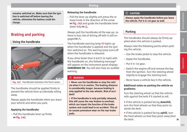
Driving
remains switched on. Make sure that the igni-tion is switched off before leaving thevehicle, otherwise the battery could dis-charge.
Braking and parking
Using the handbrake
Fig. 142 Handbrake between the front seats.
The handbrake should be applied firmly toprevent the vehicle from accidentally rollingaway.
Always apply the handbrake when you leaveyour vehicle and when you park.
Applying the handbrake
– Pull the handbrake lever up firmly››› Fig. 142.
Releasing the handbrake
– Pull the lever up slightly and press the re-lease knob in the direction of the arrow››› Fig. 142 and guide the handbrake leverdown fully ››› .
Always pull the handbrake all the way up, sothere is less risk of driving off with it still en-gaged ››› .
The handbrake warning lamp lights upwhen the handbrake is applied and the igni-tion switched on. The warning lamp turns offwhen the handbrake is released.
If you drive faster than 6 km/h (4 mph) withthe handbrake on, the following message*will appear on the instrument panel display:HANDBRAKE ON. You will also hear an audiblewarning.
WARNING
● Never use the handbrake to stop the vehi-cle when it is in motion. The braking distanceis considerably longer, because braking isonly applied to the rear wheels. Risk of acci-dent!
● If the handbrake is only partially released,this will cause the rear brakes to overheat,which can impair the function of the brakesystem and could lead to an accident. This al-so causes premature wear on the rear brakepads.
CAUTION
Always apply the handbrake before you leavethe vehicle. Put it in 1st gear as well.
Parking
The handbrake should always be firmly ap-plied when the vehicle is parked.
Always note the following points when park-ing the vehicle:
– Use the brake pedal to stop the vehicle.
– Apply the handbrake.
– Put it in 1st gear.
– Switch the engine off and remove the keyfrom the ignition. Turn the steering wheelslightly to engage the steering lock.
– Never leave a vehicle key in the vehicle.
Additional notes on parking the vehicle ongradients:
Turn the steering wheel so that the vehiclerolls against the kerb if it started to roll.
● If the vehicle is parked facing downhill,turn the front wheels so that they point to-wards the kerb.
● If the vehicle is parked facing uphill, turnthe front wheels so that they point away fromthe kerb. »
131
Tech
nical
spec
ificati
ons
Adv
ice
Ope
rati
onS
afet
yTh
e es
sent
ials
Operation
● Secure the vehicle as usual by applying thehandbrake firmly and putting it in 1st gear.
WARNING
● Take measures to reduce the risk of injurywhen you leave your vehicle unattended.
● Never park where the hot exhaust systemcould ignite inflammable materials, such asdry grass, low bushes, spilt fuel etc.
● Never allow vehicle occupants to remain inthe vehicle when it is locked. They would beunable to open the vehicle from the inside,and could become trapped in the vehicle inan emergency. In the event of an emergency,locked doors will delay assistance to vehicleoccupants.
● Never leave children alone in the vehicle.They could set the vehicle in motion, for ex-ample, by releasing the handbrake or thegearbox lever.
● Depending on weather conditions, it maybecome extremely hot or cold inside the vehi-cle. This can be fatal.
Manual gearbox
Changing gears
Read the additional information carefully››› page 24
In some countries the clutch pedal must befully pressed down for the engine to start.
Selecting reverse gear
● Engage reverse gear only when the vehicleis stopped.
Changing down gears
While driving, changing down a gear must al-ways be done gradually, i.e. to the gear di-rectly below and when the engine speed isnot too high ››› . Changing down while by-passing one or various gears at high speedsor at high engine speeds can damage theclutch and the gearbox, even if the clutchpedal remains depressed ››› .
WARNING
When the engine is running, the vehicle willstart to move as soon as a gear is engagedand the clutch released. This is also the casewith the electro-mechanical parking brakeswitched on.
● Never engage reverse gear when the vehi-cle is moving.
WARNING
If the gear is changed down inappropriatelyby selecting a gear that is too low, you maylose control of the vehicle, causing an acci-dent and serious injuries.
CAUTION
When travelling at high speeds or at high en-gine speeds, selecting a gear that is too low
can cause considerable damage to the clutchand the gearbox. This can also occur if theclutch pedal is pressed and held and it doesnot engage.
CAUTION
To prevent damage and avoid prematurewear, please observe the following:
● Do not rest your hand on the gear leverwhile driving. The pressure applied by yourhand is transmitted to the gearbox selectorforks.
● Always ensure that the vehicle is complete-ly stopped before engaging the reverse gear.
● Always press the clutch to the floor whenchanging gears.
● Never hold the vehicle “on the clutch” onhills with the engine on.
Automatic gearbox/DSGautomatic gearbox*
Introduction
Your vehicle is equipped with an electronical-ly controlled manual gearbox. Torque be-tween the engine and the gearbox is trans-mitted via two independent clutches. They re-place the torque converter found on conven-tional automatic gearboxes and allow for
132

Driving
smooth, uninterrupted acceleration of thevehicle.
The tiptronic system allows the driver tochange gears manually if desired››› page 135, Changing gears in tiptronicmode*.
Selector lever positions
Read the additional information carefully››› page 25
The selector lever position engaged is high-lighted on the display in the instrument clus-ter. With the selector lever in the manualgearbox positions G, D, E and S, the engagedgear is also indicated on the display.
P – Parking lock
When the selector lever is in this position,the driven wheels are locked mechanically.The parking lock must be engaged only whenthe vehicle is stationary ››› .
The interlock button (the button on the selec-tor lever handle) must be pressed in and si-multaneously the brake pedal must be de-pressed before moving the selector lever ei-ther in or out of position P.
R – Reverse gear
Reverse gear must be engaged only when thevehicle is stationary and the engine is idling››› .
To move the selector lever to position R, theinterlock button must be pressed in and atthe same time the brake pedal must be de-pressed. The reverse lights come on whenthe selector lever is in the R position with theignition on.
N – Neutral (idling)
With the selector lever in this position, thegear is in neutral.
D/S – Permanent drive (forward) position
The selector lever in the D/S position enablesthe gears to be controlled in normal mode (D)or Sport (S). To select Sport mode (S), movethe selector lever backwards. Moving the lev-er again will select normal mode (D). The se-lected driving mode is shown on the instru-ment panel display.
In normal mode (D), the gearbox automatical-ly selects the best gear ratio. This dependson the engine load, the road speed and thedynamic gear control programme (DCP).
Sport mode (S) must be selected for a sportydriving style. This setting makes use of theengine's maximum power output. When ac-celerating the gear shifts will be noticeable.
The brake pedal must be pressed when mov-ing the selector lever from D/S to N if the ve-hicle is stationary or at speeds below 5 km/h(3 mph) ››› .
Under certain circumstances (e.g. when driv-ing in mountains) it can be advantageous toswitch temporarily to tiptronic mode››› page 135, in order to manually select gearratios to suit the driving conditions.
WARNING
● Take care not to accidentally press the ac-celerator pedal when the vehicle is stopped.The vehicle could otherwise start moving im-mediately (in some cases even if the parkingbrake is engaged) resulting in the risk of anaccident.
● Never move the selector lever to R or Pwhen driving. Failure to follow this instruc-tion could result in an accident.
● With selector lever in any position (exceptP) the vehicle must always be held with thefoot brake when the engine is running. This isbecause an automatic gearbox still transmitspower even at idling speed, and the vehicletends to “creep”). The accelerator pedal muston no account be pressed inadvertently whena gear is engaged with the vehicle stationary.The vehicle could otherwise start moving im-mediately (in some cases even if the parkingbrake is engaged) resulting in the risk of anaccident. »
133
Tech
nical
spec
ificati
ons
Adv
ice
Ope
rati
onS
afet
yTh
e es
sent
ials

Operation
● While you are selecting a gear and the vehi-cle is stopped with the engine running, donot accelerate. Failure to follow this instruc-tion could result in an accident.
● As a driver you should never leave your ve-hicle if the engine is running and a gear is en-gaged. If you have to leave your vehicle whilethe engine is running, you must apply thehandbrake and engage the parking lock (P).
● To avoid accidents, apply the handbrakeand put the selector lever in position P beforeopening the bonnet and working on the vehi-cle with the engine running. Please alwaysobserve the important safety warnings››› page 198, Work in the engine compart-ment.
Note
● If the selector lever is moved accidentallyto N when driving, release the accelerator andlet the engine speed drop to idling before se-lecting gear range D or S again.
● Should the power supply to the selectorlever be interrupted in position P, the selectorlever will be locked. If this should happen themanual release can be used ››› page 229.
Selector lever lock
Fig. 143 Selector lever lock.
The selector lever lock prevents gears frombeing engaged inadvertently, so that the ve-hicle is not set in motion unintentionally.
The selector lever lock is released as follows:
– Switch the ignition on.
– Press the brake pedal and at the same timepress in the interlock button.
Automatic selector lever lock
With the ignition switched on, the selectorlever is locked in the positions P and N. Thebrake pedal must be pressed to release thelever while pressing the release button if theselector lever is in the position P. As a re-minder for the driver, with the lever in posi-tions P or N the following message will beshown on the display:
When stationary, apply footbrake while se-lecting a gear.
The selector lever lock only works if the vehi-cle is stationary or driving at speeds up to 5km/h. At higher speeds the selector leverlock in the N position is disengaged automat-ically.
The selector lever lock is not engaged if theselector lever is moved quickly through posi-tion N (e.g. when shifting from R to D). Thismakes it possible, for instance, to rock thevehicle “backwards and forwards” if it isstuck. The selector lever lock engages auto-matically if the brake pedal is not depressedand the lever is in position N for more thanabout two seconds.
Interlock button
The interlock button on the selector leverhandle prevents the driver from inadvertentlyengaging certain gears. Press the button into disengage the selector lever lock. The se-lector lever positions in which the interlockbutton has to be pressed are shown in the il-lustration, highlighted in colour ››› Fig. 143.
Safety interlock for ignition key
Once the ignition has been turned off, thekey may be removed only if the gear selectoris in position P. While the key is not in the ig-nition, the selector lever is locked in positionP.
134
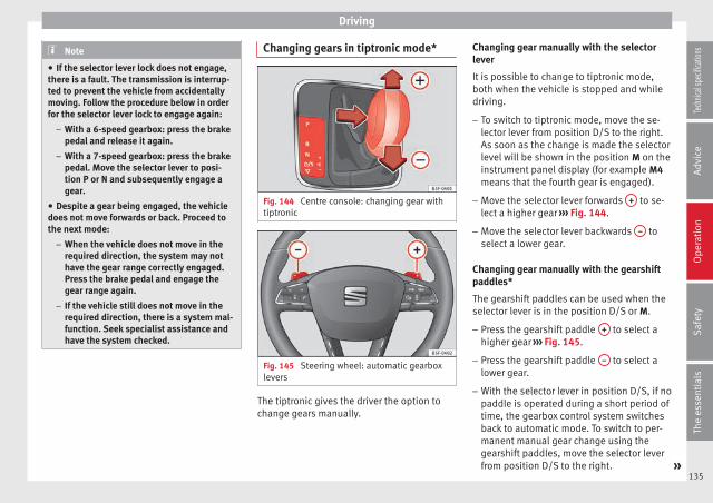
Driving
Note
● If the selector lever lock does not engage,there is a fault. The transmission is interrup-ted to prevent the vehicle from accidentallymoving. Follow the procedure below in orderfor the selector lever lock to engage again:
– With a 6-speed gearbox: press the brakepedal and release it again.
– With a 7-speed gearbox: press the brakepedal. Move the selector lever to posi-tion P or N and subsequently engage agear.
● Despite a gear being engaged, the vehicledoes not move forwards or back. Proceed tothe next mode:
– When the vehicle does not move in therequired direction, the system may nothave the gear range correctly engaged.Press the brake pedal and engage thegear range again.
– If the vehicle still does not move in therequired direction, there is a system mal-function. Seek specialist assistance andhave the system checked.
Changing gears in tiptronic mode*
Fig. 144 Centre console: changing gear withtiptronic
Fig. 145 Steering wheel: automatic gearboxlevers
The tiptronic gives the driver the option tochange gears manually.
Changing gear manually with the selectorlever
It is possible to change to tiptronic mode,both when the vehicle is stopped and whiledriving.
– To switch to tiptronic mode, move the se-lector lever from position D/S to the right.As soon as the change is made the selectorlevel will be shown in the position M on theinstrument panel display (for example M4means that the fourth gear is engaged).
– Move the selector lever forwards + to se-lect a higher gear ››› Fig. 144.
– Move the selector lever backwards – toselect a lower gear.
Changing gear manually with the gearshiftpaddles*
The gearshift paddles can be used when theselector lever is in the position D/S or M.
– Press the gearshift paddle + to select ahigher gear ››› Fig. 145.
– Press the gearshift paddle – to select alower gear.
– With the selector lever in position D/S, if nopaddle is operated during a short period oftime, the gearbox control system switchesback to automatic mode. To switch to per-manent manual gear change using thegearshift paddles, move the selector leverfrom position D/S to the right. »
135
Tech
nical
spec
ificati
ons
Adv
ice
Ope
rati
onS
afet
yTh
e es
sent
ials
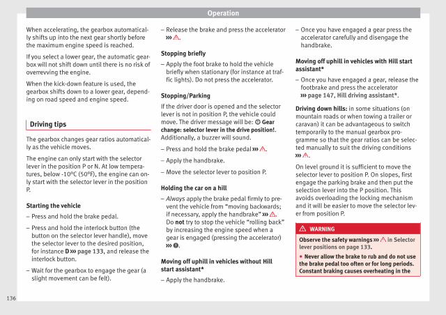
Operation
When accelerating, the gearbox automatical-ly shifts up into the next gear shortly beforethe maximum engine speed is reached.
If you select a lower gear, the automatic gear-box will not shift down until there is no risk ofoverrevving the engine.
When the kick-down feature is used, thegearbox shifts down to a lower gear, depend-ing on road speed and engine speed.
Driving tips
The gearbox changes gear ratios automatical-ly as the vehicle moves.
The engine can only start with the selectorlever in the position P or N. At low tempera-tures, below -10°C (50°F), the engine can on-ly start with the selector lever in the positionP.
Starting the vehicle
– Press and hold the brake pedal.
– Press and hold the interlock button (thebutton on the selector lever handle), movethe selector lever to the desired position,for instance D ››› page 133, and release theinterlock button.
– Wait for the gearbox to engage the gear (aslight movement can be felt).
– Release the brake and press the accelerator››› .
Stopping briefly
– Apply the foot brake to hold the vehiclebriefly when stationary (for instance at traf-fic lights). Do not press the accelerator.
Stopping/Parking
If the driver door is opened and the selectorlever is not in position P, the vehicle couldmove. The driver message will be: Gearchange: selector lever in the drive position!.Additionally, a buzzer will sound.
– Press and hold the brake pedal ››› .
– Apply the handbrake.
– Move the selector lever to position P.
Holding the car on a hill
– Always apply the brake pedal firmly to pre-vent the vehicle from “moving backwards;if necessary, apply the handbrake” ››› .Do not try to stop the vehicle “rolling back”by increasing the engine speed when agear is engaged (pressing the accelerator)››› .
Moving off uphill in vehicles without Hillstart assistant*
– Apply the handbrake.
– Once you have engaged a gear press theaccelerator carefully and disengage thehandbrake.
Moving off uphill in vehicles with Hill startassistant*
– Once you have engaged a gear, release thefootbrake and press the accelerator››› page 147, Hill driving assistant*.
Driving down hills: in some situations (onmountain roads or when towing a trailer orcaravan) it can be advantageous to switchtemporarily to the manual gearbox pro-gramme so that the gear ratios can be selec-ted manually to suit the driving conditions››› .
On level ground it is sufficient to move theselector lever to position P. On slopes, firstengage the parking brake and then put theselection lever into the P position. Thisavoids overloading the locking mechanismand it will be easier to move the selector lev-er from position P.
WARNING
Observe the safety warnings ››› in Selectorlever positions on page 133.
● Never allow the brake to rub and do not usethe brake pedal too often or for long periods.Constant braking causes overheating in the
136
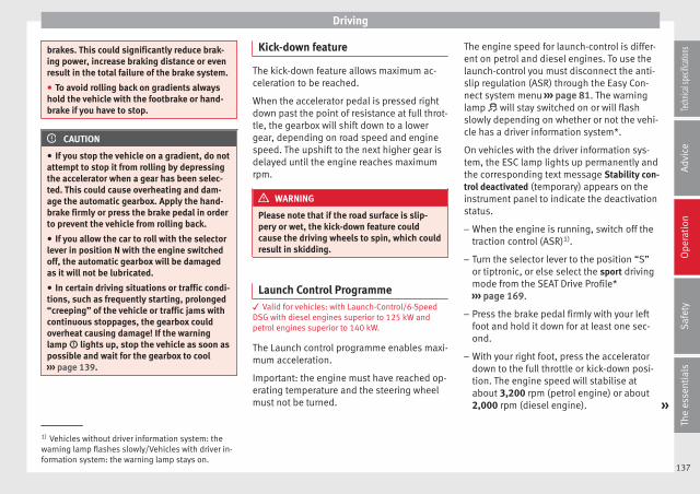
Driving
brakes. This could significantly reduce brak-ing power, increase braking distance or evenresult in the total failure of the brake system.
● To avoid rolling back on gradients alwayshold the vehicle with the footbrake or hand-brake if you have to stop.
CAUTION
● If you stop the vehicle on a gradient, do notattempt to stop it from rolling by depressingthe accelerator when a gear has been selec-ted. This could cause overheating and dam-age the automatic gearbox. Apply the hand-brake firmly or press the brake pedal in orderto prevent the vehicle from rolling back.
● If you allow the car to roll with the selectorlever in position N with the engine switchedoff, the automatic gearbox will be damagedas it will not be lubricated.
● In certain driving situations or traffic condi-tions, such as frequently starting, prolonged“creeping” of the vehicle or traffic jams withcontinuous stoppages, the gearbox couldoverheat causing damage! If the warninglamp lights up, stop the vehicle as soon aspossible and wait for the gearbox to cool››› page 139.
Kick-down feature
The kick-down feature allows maximum ac-celeration to be reached.
When the accelerator pedal is pressed rightdown past the point of resistance at full throt-tle, the gearbox will shift down to a lowergear, depending on road speed and enginespeed. The upshift to the next higher gear isdelayed until the engine reaches maximumrpm.
WARNING
Please note that if the road surface is slip-pery or wet, the kick-down feature couldcause the driving wheels to spin, which couldresult in skidding.
Launch Control Programme3 Valid for vehicles: with Launch-Control/6-SpeedDSG with diesel engines superior to 125 kW andpetrol engines superior to 140 kW.
The Launch control programme enables maxi-mum acceleration.
Important: the engine must have reached op-erating temperature and the steering wheelmust not be turned.
The engine speed for launch-control is differ-ent on petrol and diesel engines. To use thelaunch-control you must disconnect the anti-slip regulation (ASR) through the Easy Con-nect system menu ››› page 81. The warninglamp will stay switched on or will flashslowly depending on whether or not the vehi-cle has a driver information system*.
On vehicles with the driver information sys-tem, the ESC lamp lights up permanently andthe corresponding text message Stability con-trol deactivated (temporary) appears on theinstrument panel to indicate the deactivationstatus.
– When the engine is running, switch off thetraction control (ASR)1).
– Turn the selector lever to the position “S”or tiptronic, or else select the sport drivingmode from the SEAT Drive Profile*››› page 169.
– Press the brake pedal firmly with your leftfoot and hold it down for at least one sec-ond.
– With your right foot, press the acceleratordown to the full throttle or kick-down posi-tion. The engine speed will stabilise atabout 3,200 rpm (petrol engine) or about2,000 rpm (diesel engine). »
1) Vehicles without driver information system: thewarning lamp flashes slowly/Vehicles with driver in-formation system: the warning lamp stays on.
137
Tech
nical
spec
ificati
ons
Adv
ice
Ope
rati
onS
afet
yTh
e es
sent
ials

Operation
– Take your left foot off the brake pedal.
WARNING
● Always adapt your driving style to the traf-fic conditions.
● Only use the launch control programmewhen road and traffic conditions permit, andmake sure your manner of driving and accel-erating the vehicle does not inconvenience orendanger other road users.
● Make sure that the ESC remains switchedon. Please note that when the ASR and ESCare deactivated, the wheels may start to spin,causing the vehicle to lose grip. Risk of acci-dent!
● After putting the vehicle into gear, the“sport” mode of the ESC should be deactiva-ted again by briefly pressing the OFF but-ton.
Note
● After using the Launch control programme,the temperature in the gearbox may have in-creased considerably. In this case, the pro-gramme could be disabled for several mi-nutes. The programme can be used again af-ter the cooling phase.
● Accelerating with the Launch control pro-gramme places a heavy load on all parts ofthe vehicle. This can result in increased wearand tear.
Downhill speed control*
The downhill speed control function helpsthe driver when driving down steep gradi-ents.
Downhill speed control is activated when theselector lever is in D/S and the driver appliesthe foot brake. The automatic gearbox auto-matically engages a lower gear that is suita-ble for the slope. The downhill speed controlfunction attempts to maintain the speed atwhich the vehicle was travelling when thefoot brake was applied (subject to the laws ofphysics and technical drive limitations). Itmay be necessary to adjust the speed againusing the foot brake in certain situations. Giv-en that the downhill speed control can onlychange down to 3rd gear, on very steep de-scents the tiptronic mode may be required. Inthis case, manually reduce the tiptronic to2nd or 1st gear to use the engine brake andreduce the charge on the brakes.
Downhill speed control is deactivated assoon as the road levels out again or youpress the accelerator pedal.
On vehicles with cruise control system*››› page 150, downhill speed control is acti-vated when you set a cruising speed.
WARNING
The downhill speed control cannot defy thelaws of physics. Therefore, speed cannot be
maintained constant in all situations. Alwaysbe prepared to use the brakes!
Inertia mode
The inertia mode enables the kinetic energyof the vehicle to be harnessed enabling cer-tain stretches to be driven without using theaccelerator. This enables fuel to be saved.Use the inertia mode to “let the vehicle roll”before, for example, arriving in a town.
Switching on inertia mode
Important: selector lever must be in positionD, gradients below 12 %.
– Select, in SEAT Drive Profile*, Eco mode››› page 169.
– Take your foot off the accelerator.
The driver message Inertia will be displayed.At speeds higher than 20 km/h (12 mph), thegearbox will automatically disengage and thevehicle will roll freely, without the effect ofthe engine brake. While the vehicle rolls, theengine runs at idling speed.
Stopping inertia mode
– Press the brake or the accelerator pedal.
To make use of the braking force and switchoff the engine again, simply press the brakepedal briefly.
138

Driving
Applying both the inertia mode (= prolongedsection with less energy) and the switchingoff using inertia (= shorter section withoutthe need for fuel) facilitates improved fuelconsumption and emission balance.
WARNING
● If the inertia mode has been switched on,take into account, when approaching an ob-stacle and releasing the accelerator pedal,that the vehicle will not decelerate in the usu-al manner: risk of accident!
● When using inertia mode while travellingdown hills, the vehicle can increase speed:risk of accident!
● If other users drive your vehicle, warn themabout inertia mode.
Note
● Inertia mode is only available in eco (SEATDrive Profile*) driving mode.
● The driver message Inertia is only displayedwith the current consumption. In inertiamode the gear will no longer be displayed(for example “E” will appear instead of “E7”).
● On downhill sections with gradients above15 %, the inertia mode will automatically beswitched off temporarily.
Backup programme
A backup programme is in place if a faultshould occur in the control system.
If all the positions of the selector lever areshown over a light background on the instru-ment panel display, there is a system faultand the automatic gearbox will operate inwith the backup programme. When the back-up programme is activated, it is possible todrive the vehicle, however, at low speeds andwithin a selected range of gears. In some ca-ses driving in reverse gear may not be possi-ble.
CAUTION
If the gearbox operates with the backup pro-gramme, take the vehicle to a specialisedworkshop and have the fault repaired withoutdelay.
Clutch
Clutch overheating! Please stop!
The clutch has overheated and could be dam-aged. Stop the vehicle and wait for the gear-box to cool with the engine at idling speedand the selector lever in position P. When thewarning lamp and the driver message switchoff, have the fault corrected by a specialisedworkshop without delay. If the warning lampand the driver message do not switch off, do
not continue driving. Seek specialist assis-tance.
Faults in the gearbox
Gearbox: Fault! Stop the vehicle and placethe lever in the position P.
There is a fault in the gearbox. Stop the vehi-cle in a safe place and do not continue driv-ing. Seek specialist assistance.
Gearbox: System fault! You may continuedriving.
Have the fault corrected by a specialisedworkshop without delay.
Gearbox: System fault! You can continuedriving with restrictions. Reverse gear disa-bled
Take the vehicle to a specialised workshopand have the fault repaired without delay.
Gearbox: System fault! You can continuedriving in D until switching off the engine
Stop the vehicle in a safe place well awayfrom moving traffic. Seek specialist assis-tance.
Gearbox: too hot. Adapt your driving ac-cordingly
Continue driving at moderate speeds. Whenthe warning lamp switches off, you can con-tinue driving in a normal manner. »
139
Tech
nical
spec
ificati
ons
Adv
ice
Ope
rati
onS
afet
yTh
e es
sent
ials

Operation
Gearbox: press the brake and engage agear again.
If the fault was caused by a gearbox with ahigh temperature, this driver message will bedisplayed when the gearbox has cooledagain.
Run-in and economical driving
Running in the engine
A new vehicle should be run in over a dis-tance of 1500 km (1000 miles). For the first1,000 km the engine speed should not ex-ceed 2/3 of the maximum permissible enginespeed. In doing so, do not accelerate at fullthrottle and do not drive with a trailer! From1000 to 1500 km (600 to 1000 miles) youcan gradually increase the engine rpm androad speed.
During its first few hours of running, the in-ternal friction in the engine is greater thanlater on when all the moving parts have bed-ded down.
How the vehicle is driven for the first 1,500km influences the future engine perform-ance. Subsequently, also drive at a moderaterate, especially when the engine is still cold:this will lead to less engine wear and tearand will prolong its useful life.
You should also avoid driving with the enginespeed too low. Change down to a lower gearwhen the engine no longer runs “smoothly”.If the engine revs too much, cut fuel injectionto protect the engine.
Environmental friendliness
Environmental protection is a top priority inthe design, choice of materials and manufac-ture of your new SEAT.
Constructive measures to encouragerecycling
● Joints and connections designed for easydismantling
● Modular construction to facilitate disman-tling
● Increased use of single-grade materials.
● Plastic parts and elastomers are marked inaccordance with ISO 1043, ISO 11469 andISO 1629.
Choice of materials
● Use of recycled materials.
● Use of compatible plastics in the same partif its components are not easily separated.
● Use of recycled materials and/or materialsoriginating from renewable sources.
● Reduction of volatile components, includ-ing odour, in plastic materials.
● Use of CFC-free coolants.
Ban on heavy metals, with the exceptionsdictated by law (Annex II of ELV Directive2000/53/EC): cadmium, lead, mercury, hexa-valent chromium.
Manufacturing methods
● Reduction of the quantity of thinner in theprotective wax for cavities.
● Use of plastic film as protection during ve-hicle transport.
● Use of solvent-free adhesives.
● Use of CFC-free coolants in cooling sys-tems.
● Recycling and energy recovery from resi-dues (RDF).
● Improvement in the quality of waste water.
● Use of systems for the recovery of residualheat (thermal recovery, enthalpy wheels,etc.).
● The use of water-soluble paints.
140
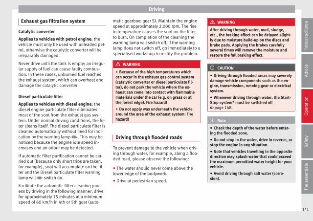
Driving
Exhaust gas filtration system
Catalytic converter
Applies to vehicles with petrol engine: thevehicle must only be used with unleaded pet-rol, otherwise the catalytic converter will beirreparably damaged.
Never drive until the tank is empty; an irregu-lar supply of fuel can cause faulty combus-tion. In these cases, unburned fuel reachesthe exhaust system, which can overheat anddamage the catalytic converter.
Diesel particulate filter
Applies to vehicles with diesel engine: thediesel engine particulate filter eliminatesmost of the soot from the exhaust gas sys-tem. Under normal driving conditions, the fil-ter cleans itself. The diesel particulate filter iscleaned automatically without need for indi-cation by the warning lamp . This may benoticed because the engine idle speed in-creases and an odour may be detected.
If automatic filter purification cannot be car-ried out (because only short trips are taken,for example), soot will accumulate on the fil-ter and the Diesel particulate filter warninglamp will switch on.
Facilitate the automatic filter cleaning proc-ess by driving in the following manner: drivefor approximately 15 minutes at a minimumspeed of 60 km/h in 4th or 5th gear (auto-
matic gearbox: gear S). Maintain the enginespeed at approximately 2,000 rpm. The risein temperature causes the soot on the filterto burn. On completion of the cleaning thewarning lamp will switch off. If the warninglamp does not switch off, go immediately to aspecialised workshop to rectify the problem.
WARNING
● Because of the high temperatures whichcan occur in the exhaust gas control system(catalytic converter or diesel particulate fil-ter), do not park the vehicle where the ex-haust can come into contact with flammablematerials under the car (e.g. on grass or atthe forest edge). Fire hazard!
● Do not apply wax underneath the vehiclearound the area of the exhaust system: Firehazard!
Driving through flooded roads
To prevent damage to the vehicle when driv-ing through water, for example, along a floo-ded road, please observe the following:
● The water should never come above thelower edge of the bodywork.
● Drive at pedestrian speed.
WARNING
After driving through water, mud, sludge,etc., the braking effect can be delayed slight-ly due to moisture build-up on the discs andbrake pads. Applying the brakes carefullyseveral times will remove the moisture andrestore the full braking effect.
CAUTION
● Driving through flooded areas may severelydamage vehicle components such as the en-gine, transmission, running gear or electricalsystem.
● Whenever driving through water, the Start-Stop system* must be switched off››› page 148.
Note
● Check the depth of the water before enter-ing the flooded zone.
● Do not stop in the water, drive in reverse, orstop the engine in any situation.
● Note that vehicles travelling in the oppositedirection may splash water that could exceedthe maximum permitted water height for yourvehicle.
● Avoid driving through salt water (corro-sion).
141
Tech
nical
spec
ificati
ons
Adv
ice
Ope
rati
onS
afet
yTh
e es
sent
ials
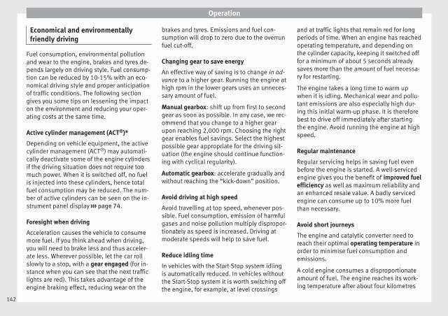
Operation
Economical and environmentallyfriendly driving
Fuel consumption, environmental pollutionand wear to the engine, brakes and tyres de-pends largely on driving style. Fuel consump-tion can be reduced by 10-15% with an eco-nomical driving style and proper anticipationof traffic conditions. The following sectiongives you some tips on lessening the impacton the environment and reducing your oper-ating costs at the same time.
Active cylinder management (ACT®)*
Depending on vehicle equipment, the activecylinder management (ACT®) may automati-cally deactivate some of the engine cylindersif the driving situation does not require toomuch power. When it is switched off, no fuelis injected into these cylinders, hence totalfuel consumption may be reduced. The num-ber of active cylinders can be seen on the in-strument panel display ››› page 74.
Foresight when driving
Acceleration causes the vehicle to consumemore fuel. If you think ahead when driving,you will need to brake less and thus acceler-ate less. Wherever possible, let the car rollslowly to a stop, with a gear engaged (for in-stance when you can see that the next trafficlights are red). This takes advantage of theengine braking effect, reducing wear on the
brakes and tyres. Emissions and fuel con-sumption will drop to zero due to the overrunfuel cut-off.
Changing gear to save energy
An effective way of saving is to change in ad-vance to a higher gear. Running the engine athigh rpm in the lower gears uses an unneces-sary amount of fuel.
Manual gearbox: shift up from first to secondgear as soon as possible. In any case, we rec-ommend that you change to a higher gearupon reaching 2,000 rpm. Choosing the rightgear enables fuel savings. Select the highestpossible gear appropriate for the driving sit-uation (the engine should continue function-ing with cyclical regularity).
Automatic gearbox: accelerate gradually andwithout reaching the “kick-down” position.
Avoid driving at high speed
Avoid travelling at top speed, whenever pos-sible. Fuel consumption, emission of harmfulgases and noise pollution multiply dispropor-tionately as speed is increased. Driving atmoderate speeds will help to save fuel.
Reduce idling time
In vehicles with the Start-Stop system idlingis automatically reduced. In vehicles withoutthe Start-Stop system it is worth switching offthe engine, for example, at level crossings
and at traffic lights that remain red for longperiods of time. When an engine has reachedoperating temperature, and depending onthe cylinder capacity, keeping it switched offfor a minimum of about 5 seconds alreadysaves more than the amount of fuel necessa-ry for restarting.
The engine takes a long time to warm upwhen it is idling. Mechanical wear and pollu-tant emissions are also especially high dur-ing this initial warm-up phase. It is thereforebest to drive off immediately after startingthe engine. Avoid running the engine at highspeed.
Regular maintenance
Regular servicing helps in saving fuel evenbefore the engine is started. A well-servicedengine gives you the benefit of improved fuelefficiency as well as maximum reliability andan enhanced resale value. A badly servicedengine can consume up to 10% more fuelthan necessary.
Avoid short journeys
The engine and catalytic converter need toreach their optimal operating temperature inorder to minimise fuel consumption andemissions.
A cold engine consumes a disproportionateamount of fuel. The engine reaches its work-ing temperature after about four kilometres
142

Driver assistance systems
(2.5 miles), when fuel consumption will re-turn to a normal level.
Check tyre pressure
Always make sure the tyres are inflated to thecorrect pressures ››› page 208 to save fuel. Ifthe pressure is below half bar, fuel consump-tion may increase by 5%. Due to the greaterrolling resistance, under-inflation also increa-ses tyre wear and impairs handling.
Do not use winter tyres all year round as theyincrease fuel consumption by up to 10%.
Avoid carrying unnecessary loads
Given that every kilo of extra weight will in-crease the fuel consumption, it is advisableto always check the luggage compartment tomake sure that no unnecessary loads are be-ing transported.
Since the luggage rack increases the aerody-namic drag of the vehicle, you should removeit when not needed. This will save, at a speedof 100-120 km/h (60-75 mph), 12% of fuel.
Save electrical energy
The engine drives the alternator, thereby gen-erating electricity. This implies that any in-crease in power consumption also increasesfuel consumption! For this reason, switch offany unneeded electrical devices. Devices thatuse a lot of electricity includes the blower at
a high setting, the rear window heating orthe seat heating*.
Driver assistance systems
Braking and stability systems
Electronic Stability Control (ESC)
The ESC helps to improve safety. It reducesthe tendency to skid and improves the stabil-ity and roadholding of the vehicle. The ESCdetects critical handling situations, such asvehicle understeer or oversteer, or wheelspinon the driving wheels. It stabilises the vehi-cle by braking individual wheels or by reduc-ing the engine torque. The warning lamp willflash on the instrument panel when the ESCis intervening .
ESC includes the Anti-lock brake system(ABS), the brake assist system, the tractioncontrol system (ASR), electronic differentiallock (EDL), electronic self-locking*, selectivetorque control* and tractor-trailer sway miti-gation*. ESC also helps stabilise the vehicleby changing the torque.
Anti-lock brake system (ABS)
ABS prevents the wheels from locking up un-der braking until the vehicle has reached avirtual standstill. You can continue to steerthe vehicle even when the brakes are on full.Keep your foot on the brake pedal and do notpump the brakes. You will feel the brake ped-al pulsate while the ABS is working. »
143
Tech
nical
spec
ificati
ons
Adv
ice
Ope
rati
onS
afet
yTh
e es
sent
ials

Operation
Brake assist system
The brake assist system can reduce the re-quired braking distance. The braking force isautomatically boosted if you press the brakepedal quickly in an emergency. You mustkeep pressing the brake pedal until the dan-ger has passed.
Traction control system (ASR)
In the event of wheelspin, the traction controlsystem reduces the engine torque to matchthe amount of grip available. This helps thecar to start moving, accelerate or climb a gra-dient.
Electronic differential lock (EDL)
When the EDL detects wheelspin, it brakesthe spinning wheel and directs the power tothe other driven wheel. This function is activeup to approximately 100 km/h.
To prevent the disc brake of the braked wheelfrom overheating, the EDL cuts out automati-cally if subjected to excessive loads. The ve-hicle can still be driven. The EDL will switchon again automatically when the brake hascooled down.
Tractor-trailer sway mitigation*
If the vehicle is pulling a trailer, it will controlthe following: Tractor-trailers tend to sway.When the swaying of the trailer is felt by thevehicle and detected by the ESC, it will auto-
matically brake the towing vehicle within thelimits of the system and mitigate the sway.Tractor-trailer sway mitigation is not availablein all countries.
Electronic self-locking*/Selective torquecontrol*
When driving around bends, an electronicself-locking intervenes. The front wheel onthe inside of the curve, or the two insidewheels, respectively, are selectively brakedas required. This minimises the traction ofthe front wheels, allowing you to take bendswith greater precision and neutrality. In cer-tain circumstances, where roads are wet orsnow-covered, the respective system may notintervene.
Multi-collision brake
In an accident, the multi-collision brake canhelp the driver by braking to avoid the risk ofskidding during the accident, which couldlead to further collisions.
The multi-collision brake works for front, sideor rear accidents, when the airbag controlunit records its activation level and the acci-dent takes place at a speed of over 10 km/h(6 mph). The ESC automatically brakes thevehicle, as long as the accident has not dam-aged the ESC, the brake hydraulics or the on-board network.
The following actions control automatic brak-ing during the accident:
● When the driver presses the accelerator,the automatic braking does not take place.
● When the braking pressure through press-ing the brake pedal is greater than the sys-tem’s braking pressure the vehicle will brakeautomatically.
● Multi-collision braking will not be availableif ESC is malfunctioning.
WARNING
● The ESC, ABS, ASR, EDL, electronic self-locking differential or selective torque controlsystems cannot exceed the limits imposed bythe laws of physics. Always bear this in mind,especially on wet or slippery roads. If you no-tice the systems cutting in, you should re-duce your speed immediately to suit the roadand traffic conditions. Do not be encouragedto take risks by the presence of more safetysystems. If you do, an accident may occur.
● Please remember that the accident risk al-ways increases if you drive fast, especially incorners or on a slippery road, or if you followtoo close behind the vehicle in front of you.The ESC, ABS, brake assist, EDL, electronicself-locking and selective torque control sys-tems cannot prevent accidents: risk of acci-dents!
144

Driver assistance systems
● Accelerate with caution on slippery surfa-ces (for example, icy or snow-covered). De-spite the control systems, the driven wheelscould spin, affecting the stability of the vehi-cle: risk of accident!
Note
● The ABS and ASR will only operate correctlyif the four wheels have identical tyres. Anydifferences in the rolling radius of the tyrescan cause the system to reduce engine powerwhen this is not desired.
● The regulating processes of the systemscan make noises when they intervene.
● If the warning lamp lights up, or alter-natively, there could be a fault ››› page 71.
Switching on/off the ESC and ASR
Fig. 146 Centre console: Button for switchingon/off the ESC and ASR
The ESC is switched on automatically whenthe engine is started, and only works whenthe engine is running and includes the ABS,EDS and ASR systems.
The ASR and ESC function should only beswitched off in situations in which traction isinsufficient, among others:
● When driving in deep snow or on surfacesthat are not very firm.
● To “free” the vehicle if it gets stuck.
Then switch the ASR and ESC function backon.
Depending on finishes and versions, it ispossible either to disconnect only the ASR orelse activate ESC Sport mode.
ESC in “Sport” mode
Sport mode can be connected via the EasyConnect ››› page 81 system menu. The abilityof the ESC to stabilise the vehicle is limited;the traction control system (ASR) becomesdisabled ››› .
The control lamp lights up. For vehicleswith a driver information system*, the driverwill be shown the electronic stability control(ESC) option: sport. Warning! Limited stability.
Disable ESC “Sport” mode
Through the Easy Connect system menu››› page 81. The warning lamp will switch
off. For vehicles with a driver information sys-tem*, the driver will be shown the electronicstability control (ESC) option: on.
Disable ASR
The Easy Connect system is used to switch offthe ASR ››› page 81. The traction control sys-tem will be disabled.
The control lamp lights up. For vehicleswith a driver information system* the driverwill be informed that ASR is disabled.
Activate ASR
The Easy Connect system ››› page 81 is usedto switch on the ASR. The traction control sys-tem will be enabled.
The control lamp switches off. For vehicleswith a driver information system* the driverwill be informed that ASR is enabled.
Disconnection of the ESC
In some versions of the model, besides thetraction control system (ASR), the electronicstability programme (ESC) can also beswitched off.
● Press the button ››› Fig. 146 for approxi-mately 1 second to switch off the ASR func-tion.
● Press the button ››› Fig. 146 for approxi-mately 3 seconds to switch off the Electronic »
145
Tech
nical
spec
ificati
ons
Adv
ice
Ope
rati
onS
afet
yTh
e es
sent
ials

Operation
Stability programme (ESC), including the ASRfunction.
● The ASR and ESC function are reconnectedby pressing the button ››› Fig. 146.
● OR: activate or deactivate the ASR or ESCfunction in the Easy Connect system bymeans of the button and the functionbuttons Setup and ESC System .
WARNING
You should switch on the ESC Sport mode on-ly if the traffic conditions and your drivingability allow you to do so safely: risk of skid-ding!
● With ESC in Sport mode, the stabilisingfunction will be limited to allow for a sportierdrive. The driving wheels could spin and thevehicle could skid.
● If the ESC/ASR is deactivated, the vehiclestabilisation function is not available.
Note
If the ASR is disconnected or the ESC’s Sportmode is selected, cruise control* will beswitched off.
Brakes
New brake pads
For the first 400 km (250 miles), new brakepads have not yet reached their maximum
braking capacity, and need to be “run in”first. However, you can compensate for theslightly reduced braking effect by applyingmore pressure on the brake pedal. Avoidoverloading the brakes while running themin.
Wear
The rate of wear on the brake pads dependsa great deal on how you drive and the condi-tions in which the vehicle is operated. This isa particular problem in urban traffic andshort stretches, or with very sporty driving.
Depending on the speed, the braking force,and the environmental conditions (for exam-ple, the temperature, air humidity, etc.)noises may be produced on braking.
Wet roads or road salt
In certain situations (for example, on drivingthrough flooded areas, in severe downpoursor after washing the vehicle) the braking ac-tion could be delayed if the discs and padsare damp, or frozen in winter. In this case thebrakes should be “dried” by pressing thebrake pedal several times.
At high speed and with the windscreen wip-ers activated, the brake pads will brieflytouch the brake discs. This takes place, al-though unnoticeable to the driver, at regularintervals to improve the response time of thebrakes when they are wet.
The effectiveness of the brakes can also betemporarily reduced if the vehicle is drivenfor some distance without using the brakeswhen there is a lot of salt on the road in win-ter. The layer of salt that accumulates on thediscs and pads can be removed by gently ap-plying the brakes a few times.
Corrosion
There may be a tendency for corrosion toform on the discs and dirt to build up on thebrake pads if the vehicle is used infrequentlyor the brakes are not used very often.
If the brakes are not used frequently, or ifrust has formed on the disks, it is advisableto clean off the pads and disks by brakingfirmly a few times at a moderately high speed››› .
Fault in the brake system
If the brake pedal travel should ever increasesuddenly, this may mean that one of the twobrake circuits has failed. Drive immediatelyto the nearest specialised workshop andhave the fault repaired. Drive there slowlyand remember that you will have to applymore pressure on the brake pedal and allowfor longer stopping distances.
146

Driver assistance systems
Low brake fluid level
Malfunctions can occur in the brake system ifthe brake fluid level is too low. The brake flu-id level is monitored electronically.
Brake servo
The brake servo increases the pressure youapply to the brake pedal. It works only whenthe engine is running.
WARNING
● Apply the brakes heavily to clean the brakesystem only in a suitable traffic situation. Donot put other road users in danger: there isrisk of causing an accident.
● Ensure the vehicle does not move while inneutral, when the engine is stopped. Failureto follow this instruction could result in anaccident.
● If the brake fluid loses its viscosity and issubjected to heavy use, vapour bubbles canform in the brake system. This reduces the ef-ficiency of the brakes.
CAUTION
● Never let the brakes “drag” by leaving yourfoot on the pedal when it is not necessary tobrake. This overheats the brakes, resulting inlonger stopping distances and greater wear.
● Before driving down a long, steep gradient,it is advisable to reduce speed and select alower gear. This makes use of engine braking
and relieves the brakes. If you still have touse the brakes, it is better to brake firmly atintervals than to apply the brakes continu-ously.
Note
● If the brake servo is out of action, for exam-ple when the car is being towed, you willhave to press the brake pedal considerablyharder than normal to make up for the lack ofservo assistance.
● If you wish to equip the vehicle with acces-sories such as a front spoiler or wheel covers,it is important that the flow of air to the frontwheels is not obstructed, otherwise thebrakes can overheat.
Hill driving assistant*
This function is only included in vehicles withESC.
The hill driving assistant helps the driver tomove off and upward on a hill when the vehi-cle is stationary.
The system maintains brake pressure for ap-proximately two seconds after the drivertakes his foot off the brake pedal to preventthe vehicle from lurching backward when it isstarted. During these 2 seconds, the driverhas enough time to release the clutch pedaland accelerate without the vehicle movingand without having to use the handbrake,
making start-up easier, more comfortableand safer.
These are the basic operation conditions:
● being on a ramp or hill/slope,
● doors closed,
● vehicle completely stationary,
● engine running and foot on the brake,
● besides having a gear engaged or being inneutral for manual gear change and with theselector lever at position S, D or R for an au-tomatic gearbox.
This system is also active when reversing up-hill.
WARNING
● If you do not start the vehicle immediatelyafter taking your foot off the brake pedal, thevehicle may start to roll back under certainconditions. Depress the brake pedal or usethe hand brake immediately.
● If the engine stalls, depress the brake ped-al or use the hand brake immediately.
● When following a line of traffic uphill, if youwant to prevent the vehicle from rolling backaccidentally when starting off, hold the brakepedal down for a few seconds before startingoff. »
147
Tech
nical
spec
ificati
ons
Adv
ice
Ope
rati
onS
afet
yTh
e es
sent
ials

Operation
Note
The Official Service or a specialist workshopcan tell you if your vehicle is equipped withthis system.
Start-Stop system*
Description and operation
The Start-Stop system helps save fuel and re-duce CO2 emissions.
In Start-Stop mode, the engine will automati-cally switch off when the vehicle stops, whenstopping at traffic lights for example. The ig-nition remains switched on during the stop-ping phase. The engine automaticallyswitches back on when required.
As soon as the ignition is switched on, theStart-Stop function is automatically activa-ted.
Basic requirements for the Start-Stop mode
● The driver door must be closed.
● The driver must have their seat belt fas-tened.
● The bonnet must be closed.
● The vehicle must have travelled at morethan 4 km/h (2 mph) since the last stop.
● The vehicle cannot be towing a trailer.
WARNING
● Never switch the engine off until the vehi-cle is stationary. The brake servo and powersteering functions will not be completely cov-ered under warranty. More force may also beneeded to turn the steering wheel or to brake.As you cannot steer and brake in the normalmanner, there is a greater risk of accidentsand serious injury.
● Never remove the key from the ignition ifthe vehicle is in motion. Otherwise, the steer-ing could lock making it impossible to steerthe vehicle.
● To avoid injury, make sure that the Start-Stop system is switched off when working inthe engine compartment ››› page 149.
CAUTION
The Start-Stop system must always beswitched off when driving through floodedareas ››› page 149.
Stop/Start the engine
Vehicles with a manual gearbox
– When the vehicle is stopped, put it intoneutral and release the clutch pedal. Theengine will switch off. The warning lamp will appear on the instrument panel dis-play.
– When the clutch pedal is pressed the en-gine will start up again. The warning lampwill switch off.
Vehicles with an automatic gearbox
– Use the foot brake to bring the vehicle to astop and keep the brake pedal presseddown with your foot. The engine will switchoff. The warning lamp will appear in thedisplay.
– When you take your foot off the brake pedalthe engine will start up again. The warninglamp will switch off.
Additional information related to theautomatic gearbox
The engine stops when the selector lever is inthe positions P, D, N and S, in addition towhen in manual mode. With the selector lev-er in position P, the engine will also remainswitched off when you take your foot off thebrake pedal. In order to start the engine upagain the accelerator must be pressed, or an-other gear engaged or the brake released.
If the selector lever is placed in position Rduring the stopping phase, the engine willstart up again.
Change from position D to P to prevent theengine from accidentally starting whenchanging and passing by position R.
148

Driver assistance systems
Note
● You can control whether the engine shouldswitch off or not by reducing or increasing thebrake force applied. While the vehicle re-mains stopped, the engine will not stop if thebrake pedal is slightly pressed, in traffic jamswith frequent stopping and starting for exam-ple. As soon as strong pressure is applied tothe brake pedal, the engine will stop.
● In vehicles with manual gearbox, duringthe stopping phases the brake pedal must re-main depressed to prevent the vehicle frommoving.
● If the engine “stalls” in vehicles with man-ual gearbox, it can be directly started upagain by immediately pressing the clutchpedal.
General notes
The system can interrupt the Start-Stop modefrequently for different reasons.
The engine does not switch off
Before the stopping phase, the system veri-fies whether certain conditions are met. Theengine does not switch off, in the followingsituations for example:
● The engine has not yet reached the mini-mum required temperature for the Start-Stopmode.
● The interior temperature selected for the airconditioner has not yet been reached.
● The interior temperature is very high/low.
● Defrost function button activated››› page 26.
● The parking aid* is switched on.
● The battery is very low.
● The steering wheel is overly turned or is be-ing turned.
● If there is a danger of misting.
● After engaging reverse gear.
● In case of a very steep gradient.
The indication is shown on the instrumentpanel display, and in addition, the driver in-formation system* shows, .
The engine starts by itself
During a stopping phase the normal Start-Stop mode can be interrupted in the follow-ing situations: The engine restarts by itselfwithout involvement from the driver.
● The interior temperature differs from thevalue selected on the air conditioner.
● Defrost function button activated››› page 26.
● The brake has been pressed several timesconsecutively.
● The battery is too low.
● High power consumption.
Note
In vehicles with an automatic gearbox, if theselector lever is placed in position D, N or Safter engaging reverse gear, the vehicle mustbe driven at a speed faster than 10 km/h (5mph) for the system to return to conditions inwhich the engine can be stopped.
Manually switching on/off the Start-Stop system
Fig. 147 Centre console: Start-Stop systembutton
If you do not wish to use the system, you canswitch it off manually.
– To manually switch on/off the Start-Stopsystem, press the button . The buttonsymbol remains lit up yellow when the sys-tem is switched off. »
149
Tech
nical
spec
ificati
ons
Adv
ice
Ope
rati
onS
afet
yTh
e es
sent
ials
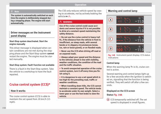
Operation
Note
The system is automatically switched on eachtime the engine is deliberately stopped dur-ing a stopping phase. The engine will startautomatically.
Driver messages on the instrumentpanel display
Start-Stop system deactivated. Start theengine manually
This driver message is displayed when cer-tain conditions are not met during the stop-ping phase and the Start-Stop system cannotrestart the engine. The engine must be star-ted manually.
Start-Stop system: Fault! Function not available
There is a fault in the Start-Stop system. Takethe vehicle to a workshop to have the faultrepaired.
Cruise control system (CCS)*
How it works
The cruise control system (CCS) is able tomaintain the set speed from 20 km/h (15mph).
The CSS only reduces vehicle speed by ceas-ing to accelerate, not by actively braking thevehicle ››› .
WARNING
Use of the cruise control could cause acci-dents and severe injuries if it is not possibleto drive at a constant speed maintaining thesafety distance.
● Do not use the cruise control in heavy traf-fic, if the distance from the vehicle in front isinsufficient, on steep roads, with severalbends or in slippery circumstances (snow,ice, rain or loose gravel), or on flooded roads.
● Never use the CCS when driving off-road oron unpaved roads.
● Always adapt your speed and the distanceto the vehicles ahead in line with visibility,weather conditions, the condition of the roadand the traffic situation.
● To avoid unexpected operation of the cruisecontrol system, turn it off every time you fin-ish using it.
● It is dangerous to use a set speed which istoo high for the prevailing road, traffic orweather conditions.
● When travelling down hills, the CCS cannotmaintain a constant speed. The vehicle tendsto accelerate under its own weight. Select alower gear or use the foot brake to slow thevehicle.
Warning and control lamp
Fig. 148 Instrument panel display: CCS statusindications
Control lamp
When the warning lamp is lit, cruise con-trol is active.
Several warning and control lamps light upfor a few seconds when the ignition is switch-ed on, signalling that the function is beingverified. They will switch off after a few sec-onds.
Displayed on the CCS screen
Status Fig. 148:
CCS temporarily switched off. The setspeed is displayed in small figures.
A
150
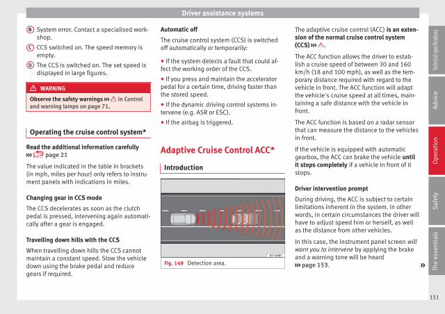
Driver assistance systems
System error. Contact a specialised work-shop.
CCS switched on. The speed memory isempty.
The CCS is switched on. The set speed isdisplayed in large figures.
WARNING
Observe the safety warnings ››› in Controland warning lamps on page 71.
Operating the cruise control system*
Read the additional information carefully››› page 21
The value indicated in the table in brackets(in mph, miles per hour) only refers to instru-ment panels with indications in miles.
Changing gear in CCS mode
The CCS decelerates as soon as the clutchpedal is pressed, intervening again automati-cally after a gear is engaged.
Travelling down hills with the CCS
When travelling down hills the CCS cannotmaintain a constant speed. Slow the vehicledown using the brake pedal and reducegears if required.
B
C
D
Automatic off
The cruise control system (CCS) is switchedoff automatically or temporarily:
● If the system detects a fault that could af-fect the working order of the CCS.
● If you press and maintain the acceleratorpedal for a certain time, driving faster thanthe stored speed.
● If the dynamic driving control systems in-tervene (e.g. ASR or ESC).
● If the airbag is triggered.
Adaptive Cruise Control ACC*
Introduction
Fig. 149 Detection area.
The adaptive cruise control (ACC) is an exten-sion of the normal cruise control system(CCS) ››› .
The ACC function allows the driver to estab-lish a cruise speed of between 30 and 160km/h (18 and 100 mph), as well as the tem-porary distance required with regard to thevehicle in front. The ACC function will adaptthe vehicle's cruise speed at all times, main-taining a safe distance with the vehicle infront.
The ACC function is based on a radar sensorthat can measure the distance to the vehiclesin front.
If the vehicle is equipped with automaticgearbox, the ACC can brake the vehicle untilit stops completely if a vehicle in front of itstops.
Driver intervention prompt
During driving, the ACC is subject to certainlimitations inherent in the system. In otherwords, in certain circumstances the driver willhave to adjust speed him or herself, as wellas the distance from other vehicles.
In this case, the instrument panel screen willwarn you to intervene by applying the brakeand a warning tone will be heard››› page 153. »
151
Tech
nical
spec
ificati
ons
Adv
ice
Ope
rati
onS
afet
yTh
e es
sent
ials
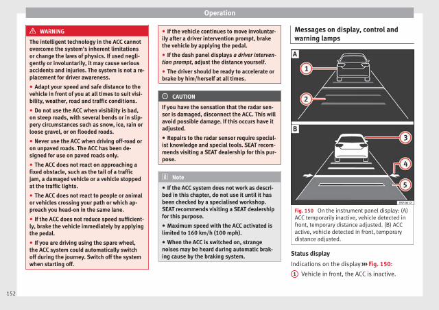
Operation
WARNING
The intelligent technology in the ACC cannotovercome the system's inherent limitationsor change the laws of physics. If used negli-gently or involuntarily, it may cause seriousaccidents and injuries. The system is not a re-placement for driver awareness.
● Adapt your speed and safe distance to thevehicle in front of you at all times to suit visi-bility, weather, road and traffic conditions.
● Do not use the ACC when visibility is bad,on steep roads, with several bends or in slip-pery circumstances such as snow, ice, rain orloose gravel, or on flooded roads.
● Never use the ACC when driving off-road oron unpaved roads. The ACC has been de-signed for use on paved roads only.
● The ACC does not react on approaching afixed obstacle, such as the tail of a trafficjam, a damaged vehicle or a vehicle stoppedat the traffic lights.
● The ACC does not react to people or animalor vehicles crossing your path or which ap-proach you head-on in the same lane.
● If the ACC does not reduce speed sufficient-ly, brake the vehicle immediately by applyingthe pedal.
● If you are driving using the spare wheel,the ACC system could automatically switchoff during the journey. Switch off the systemwhen starting off.
● If the vehicle continues to move involuntar-ily after a driver intervention prompt, brakethe vehicle by applying the pedal.
● If the dash panel displays a driver interven-tion prompt, adjust the distance yourself.
● The driver should be ready to accelerate orbrake by him/herself at all times.
CAUTION
If you have the sensation that the radar sen-sor is damaged, disconnect the ACC. This willavoid possible damage. If this occurs have itadjusted.
● Repairs to the radar sensor require special-ist knowledge and special tools. SEAT recom-mends visiting a SEAT dealership for this pur-pose.
Note
● If the ACC system does not work as descri-bed in this chapter, do not use it until it hasbeen checked by a specialised workshop.SEAT recommends visiting a SEAT dealershipfor this purpose.
● Maximum speed with the ACC activated islimited to 160 km/h (100 mph).
● When the ACC is switched on, strangenoises may be heard during automatic brak-ing cause by the braking system.
Messages on display, control andwarning lamps
Fig. 150 On the instrument panel display: (A)ACC temporarily inactive, vehicle detected infront, temporary distance adjusted. (B) ACCactive, vehicle detected in front, temporarydistance adjusted.
Status display
Indications on the display ››› Fig. 150:
Vehicle in front, the ACC is inactive.1
152
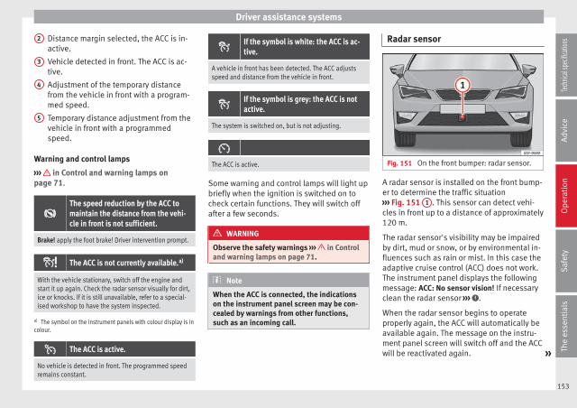
Driver assistance systems
Distance margin selected, the ACC is in-active.
Vehicle detected in front. The ACC is ac-tive.
Adjustment of the temporary distancefrom the vehicle in front with a program-med speed.
Temporary distance adjustment from thevehicle in front with a programmedspeed.
Warning and control lamps
››› in Control and warning lamps onpage 71.
The speed reduction by the ACC tomaintain the distance from the vehi-cle in front is not sufficient.
Brake! apply the foot brake! Driver intervention prompt.
The ACC is not currently available.a)
With the vehicle stationary, switch off the engine andstart it up again. Check the radar sensor visually for dirt,ice or knocks. If it is still unavailable, refer to a special-ised workshop to have the system inspected.
a) The symbol on the instrument panels with colour display is incolour.
The ACC is active.
No vehicle is detected in front. The programmed speedremains constant.
2
3
4
5
If the symbol is white: the ACC is ac-tive.
A vehicle in front has been detected. The ACC adjustsspeed and distance from the vehicle in front.
If the symbol is grey: the ACC is notactive.
The system is switched on, but is not adjusting.
The ACC is active.
Some warning and control lamps will light upbriefly when the ignition is switched on tocheck certain functions. They will switch offafter a few seconds.
WARNING
Observe the safety warnings ››› in Controland warning lamps on page 71.
Note
When the ACC is connected, the indicationson the instrument panel screen may be con-cealed by warnings from other functions,such as an incoming call.
Radar sensor
Fig. 151 On the front bumper: radar sensor.
A radar sensor is installed on the front bump-er to determine the traffic situation››› Fig. 151 1 . This sensor can detect vehi-cles in front up to a distance of approximately120 m.
The radar sensor's visibility may be impairedby dirt, mud or snow, or by environmental in-fluences such as rain or mist. In this case theadaptive cruise control (ACC) does not work.The instrument panel displays the followingmessage: ACC: No sensor vision! If necessaryclean the radar sensor ››› .
When the radar sensor begins to operateproperly again, the ACC will automatically beavailable again. The message on the instru-ment panel screen will switch off and the ACCwill be reactivated again. »
153
Tech
nical
spec
ificati
ons
Adv
ice
Ope
rati
onS
afet
yTh
e es
sent
ials

Operation
ACC operation may be affected by a strong ra-dar reverse reflection. This may occur, for ex-ample, in a closed car park or due to thepresence of metallic objects (e.g. rails on theroad or sheets used in road works).
The area in front of and around the radar sen-sor should not be covered with adhesives,additional or similar headlights, as this maynegatively affect ACC operation.
If structural modifications are made to the ve-hicle, for example, if the suspension is low-ered or the front spoiler is modified, ACC op-eration may be affected. So structural modifi-cations should only be made by specialisedworkshops. SEAT recommends visiting a SEATdealership for this purpose.
If work is done incorrectly on the front of thevehicle, the radar sensor could be damagedor lose its settings, and ACC operation maybe affected. So repair work should only bemade by specialised workshops. SEAT recom-mends visiting a SEAT dealership for this pur-pose.
CAUTION
If you have the sensation that the radar sen-sor is damaged or has lost its settings, dis-connect the ACC. This will avoid possibledamage. If this occurs have it adjusted.
● The sensor may become damaged or loseits settings when knocked, for example, dur-
ing a parking manoeuvre. This may compro-mise the system's efficacy or disconnect it.
● Repairs to the radar sensor require special-ist knowledge and special tools. SEAT recom-mends visiting a SEAT dealership for this pur-pose.
● Clean away the snow with a brush and theice preferably with a solvent-free de-icerspray.
Operating the Adaptive Cruise ControlACC
Fig. 152 On the left of the steering column:third lever for operating the Adaptive CruiseControl.
Fig. 153 On the left of the steering column:third lever for operating the Adaptive CruiseControl.
When the Adaptive Cruise Control (ACC) isconnected, the green control lamp willlight up on the instrument panel, and theprogrammed speed and ACC status will bedisplayed ››› Fig. 150.
Conditions for the adaptive cruise control tobe activated
● The selector lever must be at the D or S po-sition or in the tiptronic selection track. Inmanual gearbox any forward gear must beengaged, except the 1st gear.
● In vehicles with manual gearbox, if there isno programmed speed, drive at least at30 km/h (18 mph).
Speed control
When the ACC is connected, speed can beprogrammed and adjusted. The programmed
154
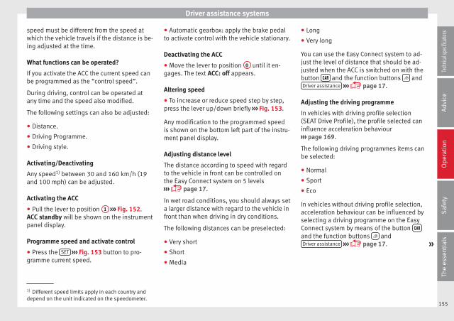
Driver assistance systems
speed must be different from the speed atwhich the vehicle travels if the distance is be-ing adjusted at the time.
What functions can be operated?
If you activate the ACC the current speed canbe programmed as the “control speed”.
During driving, control can be operated atany time and the speed also modified.
The following settings can also be adjusted:
● Distance.
● Driving Programme.
● Driving style.
Activating/Deactivating
Any speed1) between 30 and 160 km/h (19and 100 mph) can be adjusted.
Activating the ACC
● Pull the lever to position 1 ››› Fig. 152.ACC standby will be shown on the instrumentpanel display.
Programme speed and activate control
● Press the SET ››› Fig. 153 button to pro-gramme current speed.
● Automatic gearbox: apply the brake pedalto activate control with the vehicle stationary.
Deactivating the ACC
● Move the lever to position 0 until it en-gages. The text ACC: off appears.
Altering speed
● To increase or reduce speed step by step,press the lever up/down briefly ››› Fig. 153.
Any modification to the programmed speedis shown on the bottom left part of the instru-ment panel display.
Adjusting distance level
The distance according to speed with regardto the vehicle in front can be controlled onthe Easy Connect system on 5 levels››› page 17.
In wet road conditions, you should always seta larger distance with regard to the vehicle infront than when driving in dry conditions.
The following distances can be preselected:
● Very short
● Short
● Media
● Long
● Very long
You can use the Easy Connect system to ad-just the level of distance that should be ad-justed when the ACC is switched on with thebutton and the function buttons andDriver assistance ››› page 17.
Adjusting the driving programme
In vehicles with driving profile selection(SEAT Drive Profile), the profile selected caninfluence acceleration behaviour››› page 169.
The following driving programmes items canbe selected:
● Normal
● Sport
● Eco
In vehicles without driving profile selection,acceleration behaviour can be influenced byselecting a driving programme on the EasyConnect system by means of the button and the function buttons andDriver assistance ››› page 17. »
1) Different speed limits apply in each country anddepend on the unit indicated on the speedometer.
155
Tech
nical
spec
ificati
ons
Adv
ice
Ope
rati
onS
afet
yTh
e es
sent
ials

Operation
The following conditions may lead the ACCnot to react:
● If the accelerator is pressed.
● If there is no gear engaged.
● If the ESC is controlling.
● If the driver is not wearing his/her seatbelt.
● If several brake lights of the vehicle or elec-trically connected trailer are damaged.
● If the vehicle is reversing.
● Driving faster than 160 km/h (100 mph).
WARNING
There is a danger of rear collision when theminimum distance to the vehicle in front isexceeded and the speed difference betweenboth vehicles is so great that a speed reduc-tion by the ACC will not suffice. In this casethe brake pedal should be applied immedi-ately.
● The ACC may not be able to detect all situa-tions properly.
● “Stepping” on the accelerator may causethe ACC not to intervene in braking. Driverbraking will have priority over intervention bythe speed control or adaptive cruise control.
● Always be ready to use the brakes!
● Observe country-specific provisions gov-erning obligatory minimum distances be-tween vehicles.
Note
● The programmed speed is erased once theignition or the ACC are switched off.
● When the traction control system (ASR) isdeactivated during acceleration or else theESC is activated in Sport* Mode (››› page 81),the ACC switches off automatically.
● In vehicles with the Start-Stop system, theengine switches off automatically during theACC stopping phase and restarts automatical-ly to begin driving.
Vehicles with an automatic gearbox
If the vehicle is equipped with automaticgearbox, the ACC can brake the vehicle untilit stops completely if a vehicle in front of itstops.
The ACC will still be available for a few sec-onds. The vehicle will restart by itself if thevehicle in front moves (traffic jam assistant).
Disconnection criteria
The ACC will switch off if the driver appliesthe brake pedal or the driver's door isopened.
If the vehicle in front remains stationary formore than 3 seconds, the ACC will alsoswitch off for safety reasons. In this case thedriver should take control and apply thebrake.
In the latter case, when the ACC is switchedoff with the vehicle stationary, the vehiclehas to be braked by the pedal, since al-though the car is idling it can move, as thereis a gear engaged.
Restarting the vehicle with the ACC manually
The ACC can be activated again by movingthe lever to position 2 ››› Fig. 154.
WARNING
Your vehicle can start up even if there is anobstacle between your vehicle and the vehi-cle detected in front. Risk of accident!
CAUTION
● If your vehicle with ACC does not start upas expected, you can drive off by briefly step-ping on the accelerator.
● The Start-Stop system usually acts if youare driving with ACC.
156
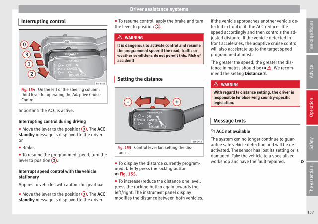
Driver assistance systems
Interrupting control
Fig. 154 On the left of the steering column:third lever for operating the Adaptive CruiseControl.
Important: the ACC is active.
Interrupting control during driving
● Move the lever to the position 3 . The ACCstandby message is displayed to the driver.or
● Brake.
● To resume the programmed speed, turn thelever to position 2 .
Interrupt speed control with the vehiclestationary
Applies to vehicles with automatic gearbox:
● Move the lever to the position 3 . The ACCstandby message is displayed to the driver.
● To resume control, apply the brake and turnthe lever to position 2 .
WARNING
It is dangerous to activate control and resumethe programmed speed if the road, traffic orweather conditions do not permit this. Risk ofaccident!
Setting the distance
Fig. 155 Control lever for: setting the dis-tance.
● To display the distance currently program-med, briefly press the rocking button››› Fig. 155.
● To increase/reduce the distance one level,press the rocking button again towards theleft/right. The instrument panel displaymodifies the distance between both vehicles.
If the vehicle approaches another vehicle de-tected in front of it, the ACC reduces thespeed accordingly and then controls the ad-justed distance. If the vehicle detected infront accelerates, the adaptive cruise controlwill also accelerate up to the target speedprogrammed at most.
The greater the speed, the greater the dis-tance in metres should be ››› . We recom-mend the setting Distance 3.
WARNING
With regard to distance setting, the driver isresponsible for observing country-specificlegislation.
Message texts
ACC not available
The system can no longer continue to guar-antee safe vehicle detection and will be de-activated. The sensor has lost its setting or isdamaged. Take the vehicle to a specialisedworkshop and have the fault repaired. »
157
Tech
nical
spec
ificati
ons
Adv
ice
Ope
rati
onS
afet
yTh
e es
sent
ials
Operation
ACC: currently not available. No sensorvision
ACC and Front Assist: currently notavailable. No sensor vision
This message will be displayed to the driver ifthe radar sensor's vision is impaired due, forexample, to leaves, snow, heavy fog or dirt.Clean the sensor.
ACC: currently not available. Gradient toosteep
The maximum road slope has been excee-ded, hence safe ACC operation cannot beguaranteed. The ACC cannot be switched on.
ACC: only available in D, S or M
Select the D/S or M position on the selectorlever.
ACC: parking brake applied
The ACC is deactivated if the parking brake isapplied. The ACC is available once again afterthe parking brake is released.
ACC: currently not available. Interventionof stability control
The message for the driver is displayed whenthe electronic stability control (ESC) inter-venes. In this case, the ACC is automaticallyswitched off.
ACC: Take action!
The message for the driver is displayed if,when the vehicle starts up on a hill with amild slope, the vehicle rolls back even al-though the ACC is activated. Apply the braketo stop the vehicle from moving/collidingwith another vehicle.
ACC: speed limit
The message for the driver is displayed if, invehicles with manual gearbox, the currentspeed is too low for the ACC mode.
The speed to be stored must be at least 30km/h. The cruise control system switches offif the speed falls below 20 km/h.
ACC: available as of the 2nd gear
The ACC is operational as of the 2nd gear(manual gearbox).
ACC: engine speed
The message for the driver is displayed if,when the AAC accelerates or brakes, the driv-er does not shift up or down a gear in time,which means exceeding or not reaching thepermissible engine speed. The AAC switchesitself off. A buzzer warning is heard.
ACC: clutch pressed
Vehicles with a manual gearbox: pressing theclutch pedal for longer abandons controlmode.
Three white dots appear if a setting madewith the control lever cannot be performed.For example, if when the vehicle is stationarythe ACC cannot be activated because thedriver is not wearing the seat belt.
Door open
Vehicles with automatic gearbox: the ACCcannot be activated with the vehicle station-ary and the door open.
Deactivating the Adaptive CruiseControl ACC temporarily in certainsituations
In the following situations the AdaptiveCruise Control (ACC) should be deactivateddue to the system's limitations ››› :
● When changing lanes, on tight bends androundabouts, in acceleration and decelera-tion lanes on motorways or in sections withroad works to prevent involuntary accelera-tion to reach the programmed speed.
● When going through a tunnel, as operationcould be affected.
● On roads with several lanes, when other ve-hicles are driving more slowly in the overtak-ing lane. In this case, slower vehicles will beovertaken on the right.
158

Driver assistance systems
● In case of heavy rain, snow or spray, as thevehicle in front might not be detected proper-ly or, in certain circumstances, might not bedetected at all.
WARNING
If the ACC does not switch off in the situa-tions described, serious accidents and inju-ries may occur.
● Always switch off the ACC in critical situa-tions.
Note
If you do not switch off the ACC in the afore-mentioned situations, you may commit a le-gal offence.
Special driving situations
Fig. 156 (A) Vehicle on a bend. (B) Motorcy-clist ahead out of range of the radar sensor.
Fig. 157 (C) Vehicle changing lanes. (D) Onevehicle turning and another stationary.
The adaptive cruise control (ACC) has certainphysical limitations inherent in the system.For example, certain reactions of the ACC, incertain circumstances, may be unexpected orcome late from the driver's point of view. Sopay attention in order to intervene if necessa-ry.
For example, the following traffic situationscall for the utmost attention: »
159
Tech
nical
spec
ificati
ons
Adv
ice
Ope
rati
onS
afet
yTh
e es
sent
ials

Operation
Deceleration until the vehicle has stopped(only vehicles with automatic gearbox)
If the vehicle in front slows down and stops,the ACC will also slow down and halt the ve-hicle. After approximately 3 seconds the sys-tem will inform the driver that he or sheshould take control of the vehicle by meansof an audible and visual warning on the in-strument panel.
Starting driving after a stopping phase (onlyvehicles with automatic gearbox)
After a stopping phase the ACC may begindriving automatically when the vehicle infront drives off.
Overtaking
When the turn signal lights up before the ve-hicle begins an overtaking manoeuvre, theACC accelerates the vehicle automaticallyand thus reduces the distance from the vehi-cle in front.
When the vehicle enters the overtaking lane,if the ACC does not detect another vehicle infront, it accelerates until it reaches the pro-grammed speed and maintains it.
System acceleration can be interrupted atany time by pressing the brake or moving thethird lever backwards ››› page 154.
Driving through a bend
On entering or exiting bends, the radar sen-sor may no longer determine the vehicle infront or react to a vehicle in the adjacent lane››› Fig. 156 A. In these situations the vehiclemay brake unnecessarily or fail to react to re-act to the vehicle in front. In this case, thedriver has to intervene by accelerating or in-terrupting the braking process by applyingthe brake or pushing the third lever back-wards ››› page 154.
Driving in tunnels
When driving through tunnels the radar sen-sor may be limited. Switch off the ACC in tun-nels.
Narrow or misaligned vehicles
The radar sensor can only detect narrow ormisaligned vehicles when they are withinrange ››› Fig. 156 B. This applies particularlyto narrow vehicles such as motorbikes. Inthese cases, you should brake as necessary.
Vehicles with special loads and accessories
Special loads and accessories of other vehi-cles that jut out over the sides, backwards orover the top may be out of the ACC's range.
Switch off the ACC when driving behind vehi-cles with special loads and accessories orwhen overtaking them. In these cases, youshould brake as necessary.
Other vehicles changing lanes
Vehicles changing lanes a short distanceaway from your own can only be detectedwhen they are within range of the sensors.Consequently, the ACC will take longer to re-act ››› Fig. 157 C. In these cases, you shouldbrake as necessary.
Stationary vehicles
The ACC does not detect stationary objectswhile driving, such as traffic tails or damagedvehicles.
If a vehicle detected by the ACC turns ormoves over and there is a stationary vehiclein front of it, the ACC will not react to it››› Fig. 157 D. In these cases, you shouldbrake as necessary.
Vehicles driving in the opposite directionand vehicles crossing your path
The ACC does not react to vehicles approach-ing from the opposite direction or vehiclescrossing your path.
Metal objects
Metal objects, e.g. rails on the road or sheetsused in road works, can confuse the radarsensor and cause the ACC to react wrongly.
160

Driver assistance systems
Factors that may affect how the radar sensoroperates
If laser sensor operation is impaired, due toheavy rain, spray, snow or mud, the ACC isdeactivated temporarily. The relevant textmessage will appear in the dash panel dis-play. If necessary, clean the radar sensor.
When the radar sensor begins to operateproperly again, the ACC will automatically beavailable again. The message on the instru-ment panel screen will switch off and the ACCwill be reactivated again.
ACC operation may be affected by a strong ra-dar reverse reflection, for example in a closedcar park.
Trailer towing
When driving with trailer the ACC controlsless dynamically.
Overheated brakes
If the brakes overheat, for example afterabrupt braking or in long and steep slopes,the ACC may be deactivated temporarily. Therelevant text message will appear in the dashpanel display. In this case, adaptive cruisecontrol cannot be activated.
Adaptive cruise control can be reactivatedonce brake temperature has cooled suffi-ciently. The message will disappear from theinstrument panel display. If the message ACCnot available remains on for quite a long time
it means that there is a fault. Contact a speci-alised workshop. SEAT recommends visitinga SEAT dealership.
WARNING
If the message ACC ready to start appears onthe instrument panel display and the vehiclein front starts up, the vehicle will start up au-tomatically. In this case the radar sensor maynot detect obstacles on the road. This couldcause an accident and serious injuries.
● Before driving off, check that the road isclear. If necessary, apply the brake.
Monitoring system FrontAssist*
Introduction
The Front Assist Monitoring system helps toprevent rear collisions.
The Front Assist can warn the driver of colli-sion hazards, prepare the vehicle for emer-gency braking in case of danger, assist thedriver on braking and cause automatic brak-ing.
The Front Assist is not a replacement fordriver awareness.
Distance warning
If the system detects that safety is endan-gered by the proximity of the vehicle in front,it may warn the driver by means of a messageon the instrument panel when driving at aspeed of between approximately 60 km/h(37 mph) and 210 km/h (130 mph)››› Fig. 158.
The warning moment varies depending onthe traffic situation and driver behaviour.
Pre-warning
If the system detects a possible collision withthe vehicle in front, it may warn the driver bymeans of an audible warning and an indica-tion on the instrument panel when driving ata speed of between approximately 30 km/h(18 mph) and 210 km/h (130 mph)››› Fig. 158.
The warning moment varies depending onthe traffic situation and driver behaviour. Atthe same time, the vehicle will prepare for apossible emergency braking ››› .
Critical warning
If the driver fails to react to the pre-warning,the system may actively intervene in thebrakes when driving at a speed of betweenapproximately 30 km/h (18 mph) and210 km/h (130 mph), generating a brief joltto warn of the imminent collision. »
161
Tech
nical
spec
ificati
ons
Adv
ice
Ope
rati
onS
afet
yTh
e es
sent
ials
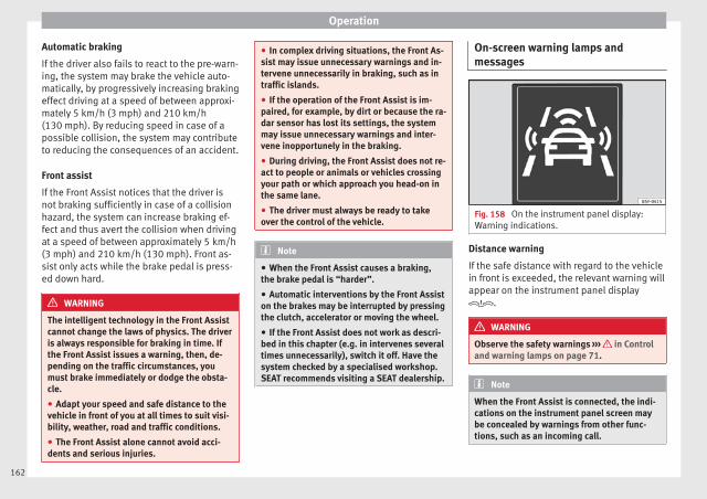
Operation
Automatic braking
If the driver also fails to react to the pre-warn-ing, the system may brake the vehicle auto-matically, by progressively increasing brakingeffect driving at a speed of between approxi-mately 5 km/h (3 mph) and 210 km/h(130 mph). By reducing speed in case of apossible collision, the system may contributeto reducing the consequences of an accident.
Front assist
If the Front Assist notices that the driver isnot braking sufficiently in case of a collisionhazard, the system can increase braking ef-fect and thus avert the collision when drivingat a speed of between approximately 5 km/h(3 mph) and 210 km/h (130 mph). Front as-sist only acts while the brake pedal is press-ed down hard.
WARNING
The intelligent technology in the Front Assistcannot change the laws of physics. The driveris always responsible for braking in time. Ifthe Front Assist issues a warning, then, de-pending on the traffic circumstances, youmust brake immediately or dodge the obsta-cle.
● Adapt your speed and safe distance to thevehicle in front of you at all times to suit visi-bility, weather, road and traffic conditions.
● The Front Assist alone cannot avoid acci-dents and serious injuries.
● In complex driving situations, the Front As-sist may issue unnecessary warnings and in-tervene unnecessarily in braking, such as intraffic islands.
● If the operation of the Front Assist is im-paired, for example, by dirt or because the ra-dar sensor has lost its settings, the systemmay issue unnecessary warnings and inter-vene inopportunely in the braking.
● During driving, the Front Assist does not re-act to people or animals or vehicles crossingyour path or which approach you head-on inthe same lane.
● The driver must always be ready to takeover the control of the vehicle.
Note
● When the Front Assist causes a braking,the brake pedal is “harder”.
● Automatic interventions by the Front Assiston the brakes may be interrupted by pressingthe clutch, accelerator or moving the wheel.
● If the Front Assist does not work as descri-bed in this chapter (e.g. in intervenes severaltimes unnecessarily), switch it off. Have thesystem checked by a specialised workshop.SEAT recommends visiting a SEAT dealership.
On-screen warning lamps andmessages
Fig. 158 On the instrument panel display:Warning indications.
Distance warning
If the safe distance with regard to the vehiclein front is exceeded, the relevant warning willappear on the instrument panel display.
WARNING
Observe the safety warnings ››› in Controland warning lamps on page 71.
Note
When the Front Assist is connected, the indi-cations on the instrument panel screen maybe concealed by warnings from other func-tions, such as an incoming call.
162

Driver assistance systems
Radar sensor
Fig. 159 On the front bumper: radar sensor.
A radar sensor is installed on the front bump-er to determine the traffic situation››› Fig. 159 1 . This sensor can detect vehi-cles in front up to a distance of approximately120 m.
The radar sensor's visibility may be impairedby dirt, mud or snow, or by environmental in-fluences such as rain or mist. In this case theFront Assist monitoring system does notwork. The instrument panel displays the fol-lowing message: Front Assist: No sensor vi-sion! If necessary clean the radar sensor ››› .
When the radar sensor begins to operateproperly again, the Front Assist will automati-cally be available again. The message willdisappear from the instrument panel display.
Front Assist operation may be affected by astrong radar reverse reflection. This may oc-cur, for example, in a closed car park or due
to the presence of metallic objects (e.g. railson the road or sheets used in road works).
The area in front of and around the radar sen-sor should not be covered with adhesives,additional or similar headlights, as this maynegatively affect Front Assist operation.
If structural modifications are made to the ve-hicle, for example, if the suspension is low-ered or the front spoiler is modified, Front As-sist operation may be affected. So structuralmodifications should only be made by speci-alised workshops. SEAT recommends visitinga SEAT dealership for this purpose.
If work is done incorrectly on the front of thevehicle, the radar sensor could be damagedor lose its settings, and Front Assist opera-tion may be affected. So repair work shouldonly be made by specialised workshops.SEAT recommends visiting a SEAT dealershipfor this purpose.
CAUTION
If you have the sensation that the radar sen-sor is damaged or has lost its settings, dis-connect the Front Assist. This will avoid pos-sible damage. If this occurs have it adjusted.
● The sensor may become damaged or loseits settings when knocked, for example, dur-ing a parking manoeuvre. This may compro-mise the system's efficacy or disconnect it.
● Repairs to the radar sensor require special-ist knowledge and special tools. SEAT recom-
mends visiting a SEAT dealership for this pur-pose.
● Clean away the snow with a brush and theice preferably with a solvent-free de-icerspray.
Operating the Front Assist monitoringsystem
Fig. 160 On the instrument panel display:Front Assist switched off message.
The Front Assist monitoring system is activewhenever the ignition is switched on.
When the Front Assist is switched off, so tooare the pre-warning function (pre warning)and the distance warning.
SEAT recommends leaving the Front Assist al-ways switched on. Exceptions ››› page 164,Switching the Front Assist Monitoring Sys-tem off in the following situations. »
163
Tech
nical
spec
ificati
ons
Adv
ice
Ope
rati
onS
afet
yTh
e es
sent
ials
Operation
Switching the Front Assist monitoringsystem on and off
With the ignition switched on, the Front As-sist can be switched on and off as follows:
● Select the corresponding menu option us-ing the button for the driver assist systems››› page 73.
● OR: switch the system on or off in the EasyConnect system with the button and thefunction buttons and Driver Assist
››› page 17.
When the Front Assist monitoring system isswitched off, the instrument panel will informthat it has been switched off with the follow-ing indicator ››› Fig. 160.
Switching the pre-warning function on or off
The pre-warning function can be switched onor off in the Easy Connect system with thebutton and the function buttons andDriver Assist ››› page 17.
The system will store the setting for the nexttime the ignition is switched on.
SEAT recommends keeping the pre-warningfunction switched on at all times.
Switching distance warning on and off
If the safe distance with regard to the vehiclein front is exceeded, the relevant warning willappear on the instrument panel display
. In this case, increase the safe dis-tance.
The distance warning function can be activa-ted or deactivated in the Easy Connect sys-tem with the button and the function but-tons and Driver Assist ››› page 17.
The system will store the setting for the nexttime the ignition is switched on.
SEAT recommends keeping the distancewarning switched on at all times.
Switching the Front Assist MonitoringSystem off in the following situations
In the following situations the Front AssistMonitoring System should be deactivateddue to the system's limitations ››› :
● When the vehicle is to be towed.
● If the vehicle is on a test bed.
● When the radar sensor is damaged.
● If the radar sensor takes a heavy knock, forexample in a rear collision.
● If it intervenes several times unnecessarily.
● If the radar sensor is covered temporarilywith some kind of accessory, such as an ad-ditional headlight or the like.
● When the vehicle is to be loaded on a lorry,ferry or train.
WARNING
If the Front Assist is not switched off in thesituations described, serious accidents andinjuries may occur.
● Switch off the Front Assist in critical situa-tions.
System limitations
The Front Assist Monitoring System has cer-tain physical limitations inherent in the sys-tem. Thus, in certain circumstances some ofthe system's reactions may be inopportuneor be delayed from the driver's standpoint.So pay attention in order to intervene if nec-essary.
The following conditions may cause the FrontAssist Monitoring System not to react or doso too late:
● On taking tight bends.
● Pressing the accelerator all the way down.
● If the Front Assist is switched off or dam-aged.
● If the ASR has been manually disconnec-ted.
● If the ESC is controlling.
● If several brake lights of the vehicle or elec-trically connected trailer are damaged.
● If the radar sensor is dirty or covered.
164
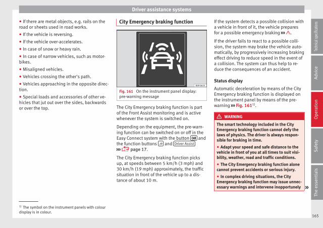
Driver assistance systems
● If there are metal objects, e.g. rails on theroad or sheets used in road works.
● If the vehicle is reversing.
● If the vehicle over-accelerates.
● In case of snow or heavy rain.
● In case of narrow vehicles, such as motor-bikes.
● Misaligned vehicles.
● Vehicles crossing the other's path.
● Vehicles approaching in the opposite direc-tion.
● Special loads and accessories of other ve-hicles that jut out over the sides, backwardsor over the top.
City Emergency braking function
Fig. 161 On the instrument panel display:pre-warning message
The City Emergency braking function is partof the Front Assist monitoring and is activewhenever the system is switched on.
Depending on the equipment, the pre-warn-ing function can be switched on or off in theEasy Connect system with the button andthe function buttons and Driver Assist
››› page 17.
The City Emergency braking function picksup, at speeds between 5 km/h (3 mph) and30 km/h (19 mph) approximately, the trafficsituation in front of the vehicle up to a dis-tance of about 10 m.
If the system detects a possible collision witha vehicle in front of it, the vehicle preparesfor a possible emergency braking ››› .
If the driver fails to react to a possible colli-sion, the system may brake the vehicle auto-matically, by progressively increasing brakingeffect driving to reduce speed in the event ofa collision. The system can thus help to re-duce the consequences of an accident.
Status display
Automatic deceleration by means of the CityEmergency braking function is displayed onthe instrument panel by means of the pre-warning ››› Fig. 1611).
WARNING
The smart technology included in the CityEmergency braking function cannot defy thelaws of physics. The driver is always respon-sible for braking in time.
● Adapt your speed and safe distance to thevehicle in front of you at all times to suit visi-bility, weather, road and traffic conditions.
● The City Emergency braking function alonecannot prevent accidents or serious injury.
● In complex driving situations, the CityEmergency braking function may issue unnec-essary warnings and intervene inopportunely »
1) The symbol on the instrument panels with colourdisplay is in colour.
165
Tech
nical
spec
ificati
ons
Adv
ice
Ope
rati
onS
afet
yTh
e es
sent
ials

Operation
in braking, such as in work areas or if thereare metal rails.
● If the operation of the City Emergency brak-ing function is impaired, for example, by dirtor because the radar sensor has lost its set-tings, the system may issue unnecessarywarnings and intervene inopportunely in thebraking.
● During driving, the City Emergency brakingfunction does not react to people or animalsor vehicles crossing your path or which ap-proach you head-on in the same lane.
Note
● When the City Emergency braking functioncauses a braking, the brake pedal is “hard-er”.
● Automatic interventions on the brakes bythe City Emergency braking function may beinterrupted by pressing the clutch, accelera-tor or moving the wheel.
● The City Emergency braking function canbrake the vehicle until it stops completely.However, the brake system does not halt thevehicle permanently. Use the foot brake!
● If several inopportune intervenes occur,switch off the Front Assist and with it the CityEmergency braking function. Take it to a spe-cialised workshop, SEAT recommends visitinga SEAT dealership.
● If numerous unnecessary interventions oc-cur, the City Emergency braking function mayswitch off automatically.
Lane Assist system*
Introduction
WARNING
The intelligent technology in the Lane Assistsystem cannot change the limits imposed bythe laws of physics and by the very nature ofthe system. Careless or uncontrolled use ofthe Lane Assist system may cause accidentsand injury. The system is not a replacementfor driver awareness.
● Always adapt your speed and the distanceto the vehicles ahead in line with visibility,weather conditions, the condition of the roadand the traffic situation.
● Always keep your hands on the steeringwheel so it can be turned at any time.
● The Lane Assist system does not detect allroad markings. The road surfaces, road struc-tures or objects in poor condition can be in-correctly detected as road markings undercertain circumstances by the Lane Assist sys-tem. In such situations, switch the Lane As-sist system off immediately.
● Please observe the indications on the in-strument panel and act as is necessary.
● Always pay attention to the vehicle's sur-roundings.
● When the area of vision of the camera be-comes dirty, covered or is damaged, the LaneAssist system function can be affected.
CAUTION
In order to avoid influencing the operation ofthe system, the following points must be tak-en into account:
● Regularly clean the area of vision of thecamera and keep it in a clean state, withoutsnow or ice.
● Do not cover the area of vision of the cam-era.
● Check that the area of vision of the wind-screen camera is not damaged.
Note
● The Lane Assist system has been exclusive-ly developed for driving on paved roads only.
● If the Lane Assist system does not work asdescribed in this chapter, do not use it andcontact a specialised workshop.
● If there is a fault in the system, have itchecked by a specialised workshop.
166
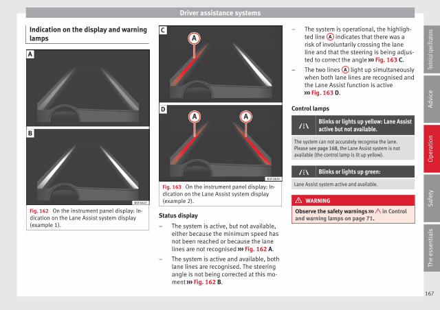
Driver assistance systems
Indication on the display and warninglamps
Fig. 162 On the instrument panel display: In-dication on the Lane Assist system display(example 1).
Fig. 163 On the instrument panel display: In-dication on the Lane Assist system display(example 2).
Status display
The system is active, but not available,either because the minimum speed hasnot been reached or because the lanelines are not recognised ››› Fig. 162 A.
The system is active and available, bothlane lines are recognised. The steeringangle is not being corrected at this mo-ment ››› Fig. 162 B.
–
–
The system is operational, the highligh-ted line A indicates that there was arisk of involuntarily crossing the laneline and that the steering is being adjus-ted to correct the angle ››› Fig. 163 C.
The two lines A light up simultaneouslywhen both lane lines are recognised andthe Lane Assist function is active››› Fig. 163 D.
Control lamps
Blinks or lights up yellow: Lane Assistactive but not available.
The system can not accurately recognise the lane.Please see page 168, the Lane Assist system is notavailable (the control lamp is lit up yellow).
Blinks or lights up green:
Lane Assist system active and available.
WARNING
Observe the safety warnings ››› in Controland warning lamps on page 71.
–
–
167
Tech
nical
spec
ificati
ons
Adv
ice
Ope
rati
onS
afet
yTh
e es
sent
ials
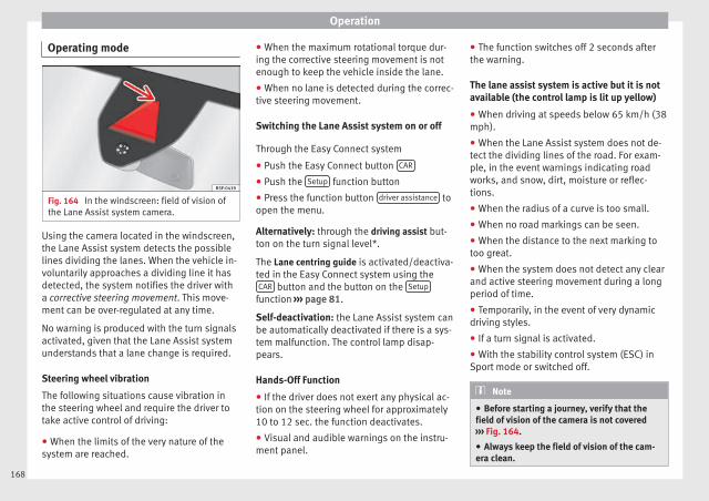
Operation
Operating mode
Fig. 164 In the windscreen: field of vision ofthe Lane Assist system camera.
Using the camera located in the windscreen,the Lane Assist system detects the possiblelines dividing the lanes. When the vehicle in-voluntarily approaches a dividing line it hasdetected, the system notifies the driver witha corrective steering movement. This move-ment can be over-regulated at any time.
No warning is produced with the turn signalsactivated, given that the Lane Assist systemunderstands that a lane change is required.
Steering wheel vibration
The following situations cause vibration inthe steering wheel and require the driver totake active control of driving:
● When the limits of the very nature of thesystem are reached.
● When the maximum rotational torque dur-ing the corrective steering movement is notenough to keep the vehicle inside the lane.
● When no lane is detected during the correc-tive steering movement.
Switching the Lane Assist system on or off
Through the Easy Connect system
● Push the Easy Connect button CAR
● Push the Setup function button
● Press the function button driver assistance toopen the menu.
Alternatively: through the driving assist but-ton on the turn signal level*.
The Lane centring guide is activated/deactiva-ted in the Easy Connect system using theCAR button and the button on the Setup
function ››› page 81.
Self-deactivation: the Lane Assist system canbe automatically deactivated if there is a sys-tem malfunction. The control lamp disap-pears.
Hands-Off Function
● If the driver does not exert any physical ac-tion on the steering wheel for approximately10 to 12 sec. the function deactivates.
● Visual and audible warnings on the instru-ment panel.
● The function switches off 2 seconds afterthe warning.
The lane assist system is active but it is notavailable (the control lamp is lit up yellow)
● When driving at speeds below 65 km/h (38mph).
● When the Lane Assist system does not de-tect the dividing lines of the road. For exam-ple, in the event warnings indicating roadworks, and snow, dirt, moisture or reflec-tions.
● When the radius of a curve is too small.
● When no road markings can be seen.
● When the distance to the next marking totoo great.
● When the system does not detect any clearand active steering movement during a longperiod of time.
● Temporarily, in the event of very dynamicdriving styles.
● If a turn signal is activated.
● With the stability control system (ESC) inSport mode or switched off.
Note
● Before starting a journey, verify that thefield of vision of the camera is not covered››› Fig. 164.
● Always keep the field of vision of the cam-era clean.
168
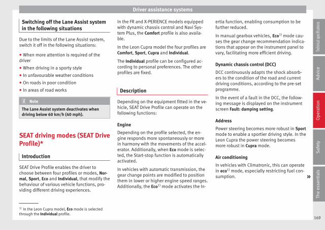
Driver assistance systems
Switching off the Lane Assist systemin the following situations
Due to the limits of the Lane Assist system,switch it off in the following situations:
● When more attention is required of thedriver
● When driving in a sporty style
● In unfavourable weather conditions
● On roads in poor condition
● In areas of road works
Note
The Lane Assist system deactivates whendriving below 60 km/h (40 mph).
SEAT driving modes (SEAT DriveProfile)*
Introduction
SEAT Drive Profile enables the driver tochoose between four profiles or modes, Nor-mal, Sport, Eco and Individual, that modify thebehaviour of various vehicle functions, pro-viding different driving experiences.
In the FR and X-PERIENCE models equippedwith dynamic chassis control and Navi Sys-tem Plus, the Comfort profile is also availa-ble.
In the Leon Cupra model the four profiles areComfort, Sport, Cupra and Individual.
The Individual profile can be configured ac-cording to personal preferences. The otherprofiles are fixed.
Description
Depending on the equipment fitted in the ve-hicle, SEAT Drive Profile can operate on thefollowing functions:
Engine
Depending on the profile selected, the en-gine responds more spontaneously or morein harmony with the movements of the accel-erator. Additionally, when Eco mode is selec-ted, the Start-stop function is automaticallyactivated.
In vehicles with automatic transmission, thegear change points are modified to positionthem in lower or higher engine speed ranges.Additionally, the Eco1) mode activates the In-
ertia function, enabling consumption to befurther reduced.
In manual gearbox vehicles, Eco1) mode cau-ses the gear change recommendation indica-tions that appear on the instrument panel tovary, facilitating more efficient driving.
Dynamic chassis control (DCC)
DCC continuously adapts the shock absorb-ers to the condition of the road and currentdriving conditions, according to the pre-setprogramme.
In the event of a fault in the DCC, the follow-ing message is displayed on the instrumentscreen Fault: damping setting.
Address
Power steering becomes more robust in Sportmode to enable a sportier driving style. In theLeon Cupra the power steering becomesmore robust in Cupra mode.
Air conditioning
In vehicles with Climatronic, this can operatein eco1) mode, especially restricting fuel con-sumption. »
1) In the Leon Cupra model, Eco mode is selectedthrough the Individual profile.
169
Tech
nical
spec
ificati
ons
Adv
ice
Ope
rati
onS
afet
yTh
e es
sent
ials
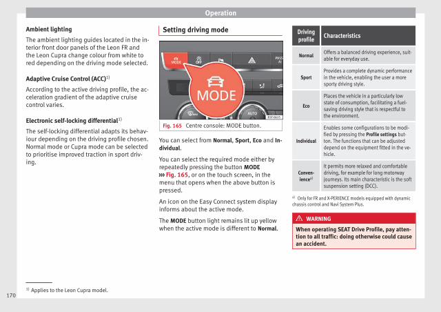
Operation
Ambient lighting
The ambient lighting guides located in the in-terior front door panels of the Leon FR andthe Leon Cupra change colour from white tored depending on the driving mode selected.
Adaptive Cruise Control (ACC)1)
According to the active driving profile, the ac-celeration gradient of the adaptive cruisecontrol varies.
Electronic self-locking differential1)
The self-locking differential adapts its behav-iour depending on the driving profile chosen.Normal mode or Cupra mode can be selectedto prioritise improved traction in sport driv-ing.
Setting driving mode
Fig. 165 Centre console: MODE button.
You can select from Normal, Sport, Eco and In-dividual.
You can select the required mode either byrepeatedly pressing the button MODE››› Fig. 165, or on the touch screen, in themenu that opens when the above button ispressed.
An icon on the Easy Connect system displayinforms about the active mode.
The MODE button light remains lit up yellowwhen the active mode is different to Normal.
Drivingprofile
Characteristics
NormalOffers a balanced driving experience, suit-able for everyday use.
SportProvides a complete dynamic performancein the vehicle, enabling the user a moresporty driving style.
Eco
Places the vehicle in a particularly lowstate of consumption, facilitating a fuel-saving driving style that is respectful tothe environment.
Individual
Enables some configurations to be modi-fied by pressing the Profile settings but-ton. The functions that can be adjusteddepend on the equipment fitted in the ve-hicle.
Conven-iencea)
It permits more relaxed and comfortabledriving, for example for long motorwayjourneys. Its main characteristic is the softsuspension setting (DCC).
a) Only for FR and X-PERIENCE models equipped with dynamicchassis control and Navi System Plus.
WARNING
When operating SEAT Drive Profile, pay atten-tion to all traffic: doing otherwise could causean accident.
1) Applies to the Leon Cupra model.170
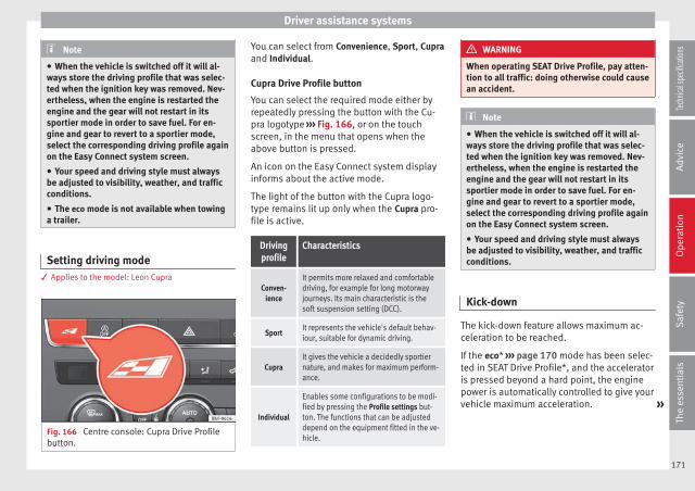
Driver assistance systems
Note
● When the vehicle is switched off it will al-ways store the driving profile that was selec-ted when the ignition key was removed. Nev-ertheless, when the engine is restarted theengine and the gear will not restart in itssportier mode in order to save fuel. For en-gine and gear to revert to a sportier mode,select the corresponding driving profile againon the Easy Connect system screen.
● Your speed and driving style must alwaysbe adjusted to visibility, weather, and trafficconditions.
● The eco mode is not available when towinga trailer.
Setting driving mode3 Applies to the model: Leon Cupra
Fig. 166 Centre console: Cupra Drive Profilebutton.
You can select from Convenience, Sport, Cupraand Individual.
Cupra Drive Profile button
You can select the required mode either byrepeatedly pressing the button with the Cu-pra logotype ››› Fig. 166, or on the touchscreen, in the menu that opens when theabove button is pressed.
An icon on the Easy Connect system displayinforms about the active mode.
The light of the button with the Cupra logo-type remains lit up only when the Cupra pro-file is active.
Drivingprofile
Characteristics
Conven-ience
It permits more relaxed and comfortabledriving, for example for long motorwayjourneys. Its main characteristic is thesoft suspension setting (DCC).
SportIt represents the vehicle's default behav-iour, suitable for dynamic driving.
CupraIt gives the vehicle a decidedly sportiernature, and makes for maximum perform-ance.
Individual
Enables some configurations to be modi-fied by pressing the Profile settings but-ton. The functions that can be adjusteddepend on the equipment fitted in the ve-hicle.
WARNING
When operating SEAT Drive Profile, pay atten-tion to all traffic: doing otherwise could causean accident.
Note
● When the vehicle is switched off it will al-ways store the driving profile that was selec-ted when the ignition key was removed. Nev-ertheless, when the engine is restarted theengine and the gear will not restart in itssportier mode in order to save fuel. For en-gine and gear to revert to a sportier mode,select the corresponding driving profile againon the Easy Connect system screen.
● Your speed and driving style must alwaysbe adjusted to visibility, weather, and trafficconditions.
Kick-down
The kick-down feature allows maximum ac-celeration to be reached.
If the eco* ››› page 170 mode has been selec-ted in SEAT Drive Profile*, and the acceleratoris pressed beyond a hard point, the enginepower is automatically controlled to give yourvehicle maximum acceleration. »
171
Tech
nical
spec
ificati
ons
Adv
ice
Ope
rati
onS
afet
yTh
e es
sent
ials

Operation
WARNING
Please note that if the road surface is slip-pery or wet, the kick-down feature couldcause the driving wheels to spin, which couldresult in skidding.
Tiredness detection (breakrecommendation)*
Introduction
The Tiredness detection informs the driverwhen their driving behaviour shows signs offatigue.
WARNING
Do not let the comfort afforded by the Tired-ness detection system tempt you into takingany risks when driving. Take regular breaks,sufficient in length when making long jour-neys.
● The driver always assumes the responsibil-ity of driving to their full capacity.
● Never drive if you are tired.
● The system does not detect the tiredness ofthe driver in all circumstances. Consult the in-formation in the section ››› page 172, Systemlimitations.
● In some situations, the system may incor-rectly interpret an intended driving manoeu-vre as driver tiredness.
● No warning is given in the event of the ef-fect called microsleep!
● Please observe the indications on the in-strument panel and act as is necessary.
Note
● Tiredness detection has been developed fordriving on motorways and well paved roadsonly.
● If there is a fault in the system, have itchecked by a specialised workshop.
Function and operation
Fig. 167 On the instrument panel display:tiredness detection symbol.
Tiredness detection determines the drivingbehaviour of the driver when starting a jour-ney, making a calculation of tiredness. This isconstantly compared with the current drivingbehaviour. If the system detects that the driv-
er is tired, an audible warning is given with asound and an optic warning is shown with asymbol and complementary message on theinstrument panel display ››› Fig. 167. Themessage on the instrument panel display isshown for approximately 5 seconds, and de-pending on the case, is repeated. The systemstores the last message displayed.
The message on the instrument panel displaycan be switched off by pressing the button on the windscreen wiper lever or thebutton on the multi function steeringwheel ››› page 72.
The message can be recalled to the instru-ment panel display using the multifunctiondisplay ››› page 72.
Conditions of operation
Driving behaviour is only calculated onspeeds above about 65 km/h (40 mph) up toaround 200 km/h (125 mph).
Switching on and off
Tiredness detection can be activated or deac-tivated in the Easy Connect system with thebutton and the function button ››› page 81. A mark indicates that the adjust-ment has been activated.
System limitations
The Tiredness detection has certain limita-tions inherent to the system. The following
172
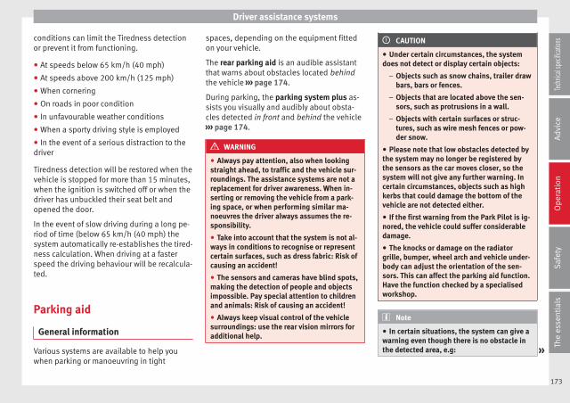
Driver assistance systems
conditions can limit the Tiredness detectionor prevent it from functioning.
● At speeds below 65 km/h (40 mph)
● At speeds above 200 km/h (125 mph)
● When cornering
● On roads in poor condition
● In unfavourable weather conditions
● When a sporty driving style is employed
● In the event of a serious distraction to thedriver
Tiredness detection will be restored when thevehicle is stopped for more than 15 minutes,when the ignition is switched off or when thedriver has unbuckled their seat belt andopened the door.
In the event of slow driving during a long pe-riod of time (below 65 km/h (40 mph) thesystem automatically re-establishes the tired-ness calculation. When driving at a fasterspeed the driving behaviour will be recalcula-ted.
Parking aid
General information
Various systems are available to help youwhen parking or manoeuvring in tight
spaces, depending on the equipment fittedon your vehicle.
The rear parking aid is an audible assistantthat warns about obstacles located behindthe vehicle ››› page 174.
During parking, the parking system plus as-sists you visually and audibly about obsta-cles detected in front and behind the vehicle››› page 174.
WARNING
● Always pay attention, also when lookingstraight ahead, to traffic and the vehicle sur-roundings. The assistance systems are not areplacement for driver awareness. When in-serting or removing the vehicle from a park-ing space, or when performing similar ma-noeuvres the driver always assumes the re-sponsibility.
● Take into account that the system is not al-ways in conditions to recognise or representcertain surfaces, such as dress fabric: Risk ofcausing an accident!
● The sensors and cameras have blind spots,making the detection of people and objectsimpossible. Pay special attention to childrenand animals: Risk of causing an accident!
● Always keep visual control of the vehiclesurroundings: use the rear vision mirrors foradditional help.
CAUTION
● Under certain circumstances, the systemdoes not detect or display certain objects:
– Objects such as snow chains, trailer drawbars, bars or fences.
– Objects that are located above the sen-sors, such as protrusions in a wall.
– Objects with certain surfaces or struc-tures, such as wire mesh fences or pow-der snow.
● Please note that low obstacles detected bythe system may no longer be registered bythe sensors as the car moves closer, so thesystem will not give any further warning. Incertain circumstances, objects such as highkerbs that could damage the bottom of thevehicle are not detected either.
● If the first warning from the Park Pilot is ig-nored, the vehicle could suffer considerabledamage.
● The knocks or damage on the radiatorgrille, bumper, wheel arch and vehicle under-body can adjust the orientation of the sen-sors. This can affect the parking aid function.Have the function checked by a specialisedworkshop.
Note
● In certain situations, the system can give awarning even though there is no obstacle inthe detected area, e.g: »
173
Tech
nical
spec
ificati
ons
Adv
ice
Ope
rati
onS
afet
yTh
e es
sent
ials

Operation
– for roads with certain surfaces, or withlong grass,
– for external ultrasound sources, such ascleaning vehicles,
– In downpours, intense snow or dense ex-haust gases
● In order to familiarise yourself with the sys-tem, it is advised that you practice parking inan area or car park that is free from traffic.There must be good weather and light condi-tions.
● The volume and tone of the warnings canbe modified, in addition to the indications››› page 176.
● In vehicles without a driver informationsystem, these parameters can be modified ina SEAT Official Service or in a specialisedworkshop.
● Please observe information on towing atrailer ››› page 177.
● The display on the Easy Connect screenshows a slight time delay.
● To ensure that the parking aid works prop-erly, the sensors must be kept clean and freeof ice and snow.
Rear parking aid*
The rear parking aid is an audible assistant.
Description
There are sensors integrated in the rearbumper. When the sensors detect an obsta-cle, you are alerted by audible warnings.
Make sure that the sensors are not coveredby adhesives, residues and the like, giventhat this could affect the system operation.Cleaning instructions ››› page 185.
The approximate measurement range of thesensors is:
rearside 0.90 m
centre 1.60 m
As you approach the obstacle, the time inter-val between the audible warnings will be re-duced. When you reach around 0.30 m thewarning will be constant: Do not continue tomove forward (or backward) ››› in Generalinformation on page 173, ››› in General in-formation on page 173 !
If you maintain separation from the obstacle,the volume of the warning begins to reduceafter four seconds (does not affect the toneof the constant warning).
Activate
When engaging reverse gear, the parking aidis automatically switched on. This is con-firmed with a short warning.
Parking system plus*
Fig. 168 Represented area.
Parking system plus assists you audibly andvisually when parking.
There are sensors integrated in the front andrear bumpers. When the sensors detect anobstacle, audible and visual warnings aregiven.
Make sure that the sensors are not coveredby adhesives, residues and the like, giventhat this could affect the system operation.Cleaning instructions ››› page 185.
The approximate measurement range of thesensors is:
1.20 m
0.90 m
1.60 m
0.90 m
A
B
C
D
174
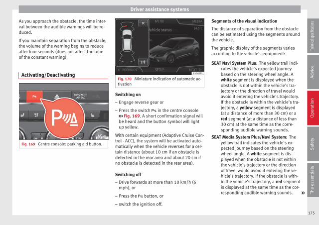
Driver assistance systems
As you approach the obstacle, the time inter-val between the audible warnings will be re-duced.
If you maintain separation from the obstacle,the volume of the warning begins to reduceafter four seconds (does not affect the toneof the constant warning).
Activating/Deactivating
Fig. 169 Centre console: parking aid button.
Fig. 170 Miniature indication of automatic ac-tivation
Switching on
– Engage reverse gear or
– Press the switch in the centre console››› Fig. 169. A short confirmation signal willbe heard and the button symbol will lightup yellow.
With certain equipment (Adaptive Cruise Con-trol - ACC), the system will be activated auto-matically when the vehicle reverses for a cer-tain distance (about 10 cm if an obstacle isdetected in the rear area and about 20 cm ifno obstacle is detected in the rear area).
Switching off
– Drive forwards at more than 10 km/h (6mph), or
– Press the button, or
– switch the ignition off.
Segments of the visual indication
The distance of separation from the obstaclecan be estimated using the segments aroundthe vehicle.
The graphic display of the segments variesaccording to the vehicle's equipment:
The yellow trail indi-cates the vehicle's expected journeybased on the steering wheel angle. Awhite segment is displayed when theobstacle is not within the vehicle's tra-jectory or the direction of travel wouldavoid it entering the vehicle's trajectory.If the obstacle is within the vehicle’s tra-jectory, a yellow segment is displayed(at a distance of more than 30 cm) or ared segment (at a distance of less than30 cm) at the same time as the corre-sponding audible warning sounds.
Theyellow trail indicates the vehicle's ex-pected journey based on the steeringwheel angle. A white segment is dis-played when the obstacle is not withinthe vehicle's trajectory or the directionof travel would avoid it entering the ve-hicle's trajectory. If the obstacle is with-in the vehicle’s trajectory, a red segmentis displayed at the same time as the cor-responding audible warning sounds. »
SEAT Navi System Plus:
SEAT Media System Plus/Navi System:
175
Tech
nical
spec
ificati
ons
Adv
ice
Ope
rati
onS
afet
yTh
e es
sent
ials
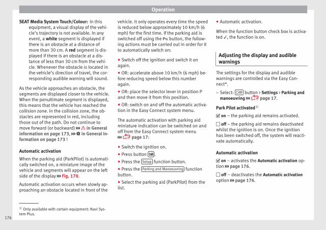
Operation
In thisequipment, a visual display of the vehi-cle’s trajectory is not available. In anyevent, a white segment is displayed ifthere is an obstacle at a distance ofmore than 30 cm. A red segment is dis-played if there is an obstacle at a dis-tance of less than 30 cm from the vehi-cle. Whenever the obstacle is located inthe vehicle’s direction of travel, the cor-responding audible warning will sound.
As the vehicle approaches an obstacle, thesegments are displayed closer to the vehicle.When the penultimate segment is displayed,this means that the vehicle has reached thecollision zone. In the collision zone, the ob-stacles are represented in red, includingthose out of the path. Do not continue tomove forward (or backward) ››› in Generalinformation on page 173, ››› in General in-formation on page 173 !
Automatic activation
When the parking aid (ParkPilot) is automati-cally switched on, a miniature image of thevehicle and segments will appear on the leftside of the display ››› Fig. 170.
Automatic activation occurs when slowly ap-proaching an obstacle located in front of the
SEAT Media System Touch/Colour: vehicle. It only operates every time the speedis reduced below approximately 10 km/h (6mph) for the first time. If the parking aid isswitched off using the button, the follow-ing actions must be carried out in order for itto automatically switch on:
● Switch off the ignition and switch it onagain.
● OR: accelerate above 10 km/h (6 mph) be-fore reducing speed below this numberagain.
● OR: place the selector lever in position Pand then move it from this position.
● OR: switch on and off the automatic activa-tion in the Easy Connect system menu.
The automatic activation with parking aidminiature indication can be switched on andoff from the Easy Connect system menu››› page 17:
● Switch the ignition on.
● Press button .
● Press the Setup function button.
● Press the Parking and Manoeuvring functionbutton.
● Select the parking aid (ParkPilot) from thelist.
● Automatic activation.
When the function button check box is activa-ted , the function is on.
Adjusting the display and audiblewarnings
The settings for the display and audiblewarnings are controlled via the Easy Con-nect*.
– Select: CAR button > Settings > Parking andmanoeuvring ››› page 17.
Park Pilot activated1)
on – the parking aid remains activated.
off – the parking aid remains deactivatedwhilst the ignition is on. Once the ignitionhas been switched off, the system will reacti-vate automatically.
Automatic activation
on – activates the Automatic activation op-tion ››› page 176.
off – deactivates the Automatic activationoption ››› page 176.
1) Only available with certain equipment: Navi Sys-tem Plus.
176

Towing bracket device
Front volume
Volume in the front and rear area.
Front sound settings/sharpness
Frequency (tone) of the sound in the frontarea.
Rear volume
Volume in the rear area.
Rear sound settings/sharpness
Frequency (tone) of the sound in the reararea.
Adjust volume
With the parking aid switched on, the activeaudio/video source volume will be reducedto the intensity of the selected setting.
You will hear a short test tone from the corre-sponding speaker each time you make a newsetting.
Error messages
When the parking aid is activated or whenswitching it on, if a continuous warning canbe heard over several seconds (additionally,in the case of Parking system plus the LED ofthe button flashes), there is a fault in thesystem. If the fault does not disappear beforeswitching off the ignition, the next time the
parking aid is switched on by engaging re-verse gear the fault will only be indicatedwith the flashing LED on the button.
Parking system plus*
If there is a fault in a sensor, the symbol isdisplayed on the Easy Connect display infront of/behind the vehicle. If a rear sensor isfaulty, only the obstacles in the areas A andB are displayed ››› Fig. 168. If a front sensor
is faulty, only the obstacles in the areas C
and D are displayed.
Have the fault corrected by a specialisedworkshop without delay.
Towing bracket
If the trailer power socket is occupied, therear parking aid sensors will not activatewhen reverse gear is engaged, or when thebutton is pressed. This function may notbe covered under warranty if the towingbracket is not factory-fitted. This causes thefollowing limitations:
Parking system plus*
There will be no warning about the presenceof obstacles in the rear area. The monitoringin the front area remains active. The opticaldisplay changes to towing mode.
Towing bracket device
Trailer towing
What do you need to bear in mindwhen towing a trailer?
Your vehicle may be used to tow a trailerwhen fitted with the correct equipment.
If you wish to retrofit a towing bracket, con-sult ››› page 180.
Connectors
Your vehicle is fitted with a 13-pin connectorfor the electrical connection between thetrailer and the vehicle.
If the trailer has a 7-pin plug you will need touse an adapter cable. It is available at anyTechnical Service.
Trailer weight/drawbar load
Never exceed the authorised trailer weight. Ifyou do not load the trailer up to the maxi-mum permitted trailer weight, you can thenclimb correspondingly steeper slopes.
The maximum trailer weights listed are onlyapplicable for altitudes up to 1000 m abovesea level. With increasing altitude the enginepower and therefore the vehicle climbingability are impaired because of the reducedair density. The maximum trailer weight has »
177
Tech
nical
spec
ificati
ons
Adv
ice
Ope
rati
onS
afet
yTh
e es
sent
ials

Operation
to be reduced accordingly. The weight of thevehicle and trailer combination must be re-duced by 10% for every further 1000 m (orpart thereof). The gross combination weightis the actual weight of the laden vehicle plusthe actual weight of the laden trailer. Whenpossible, operate the trailer with the maxi-mum permitted drawbar load on the ball jointof the towing bracket, but do not exceed thespecified limit.
The figures for trailer weights and drawbarloads that are given on the data plate of thetowing bracket are for certification purposesonly. The correct figures for your specificmodel, which may be lower than these fig-ures for the towing bracket, are given in thevehicle documentation or in ››› chapter Tech-nical Data.
Distributing the load
Distribute loads in the trailer so that heavyobjects are as near to the axle as possible.Loads carried in the trailer must be securedto prevent them moving.
Tyre pressure
Set tyre pressure to the maximum permissi-ble pressure shown on the sticker on the in-side of the fuel tank flap. Set the tyre pres-sure of the trailer tyres in accordance with thetrailer manufacturer's recommendations.
Exterior mirrors
Check whether you can see enough of theroad behind the trailer with the standard rearvision mirrors. If this is not the case, youshould have additional exterior mirrors fitted.Both exterior mirrors should be mounted onhinged extension brackets. Adjust the mirrorsto give sufficient vision to the rear.
Tow rope
Always use a cable between the vehicle andthe trailer ››› page 178.
Trailer rear lights
The trailer's rear lights should comply withthe statutory safety regulations ››› page 178.
WARNING
Never transport people in a trailer. This couldresult in fatal accidents.
Note
● Towing a trailer places additional demandson the vehicle. We recommend additionalservices between the normal inspection inter-vals if the vehicle is used frequently for tow-ing a trailer.
● Find out whether special regulations applyto towing a trailer in your country.
Hitching and connecting the trailer
Fig. 171 Schematic diagram: assignment ofthe pins of the trailer's electrical socket.
Key of the Schematic diagram ››› Fig. 171:
Pin Meaning
1 Left turn signal
2 Rear fog light
3 Earth, pins 1, 2, 4 to 8
4 Right turn signal
5 Tail light, right
6 Brake lights
7 Tail light, left
8 Reverse lights
9 Permanent live
10 Cable without positive charge
11 Earth, pin 10178
Towing bracket device
Key of the Schematic diagram ››› Fig. 171:
Pin Meaning
12 Unassigned
13 Earth, pin 9
Electrical socket for trailer
The vehicle is fitted with a 13-pole powersocket for the electrical connection betweenthe trailer and the vehicle. If the system de-tects that a trailer has been connected elec-trically, the electrical equipment on the trailerwill receive voltage through this connection.
Pin 9 has a permanent live. This powers, forexample, the trailer's interior lighting. Pin 10is only powered when the engine is running.The charge wire (pin 10) charges, for exam-ple, a caravan battery.
Pin 9 and 10 should not be connected toeach other to avoid discharging or damagingthe vehicle's battery.
The earth wires, pin 3, pin 11 and pin 13,should never be connected to each other toavoid overloading the electrical system.
If the trailer has a 7-contact connector, youwill need to use an adapter cable. In this casethe function corresponding to pin 10 will notbe available.
Trailer maximum electricity consumption
Brake lights (total) 84 Watts
Turn signal, on each side 42 Watts
Side lights (total) 100 Watts
Rear lights (total) 42 Watts
Rear fog light 42 Watts
Never exceed the values indicated!
Note
● If the rear lights of the trailer are not cor-rectly connected, the vehicle electronics maybe damaged.
● If the trailer absorbs excessive electric cur-rent, the vehicle electronics may be dam-aged.
● Never connect the trailer's electric systemdirectly to the electrical connections of thetail lights or any other power sources. Onlyuse the connections intended for providingelectric current to the trailer.
Ball coupling of towing bracket*
The ball coupling is provided with instruc-tions on fitting and removing the ball cou-pling of the towing bracket.
WARNING
The towing bracket ball coupling must bestored securely in the luggage compartmentto prevent them being flung through the vehi-cle and causing injury.
Note
● By law, the ball coupling must be removedif a trailer is not being towed if it obscuresthe number plate.
Driving tips
Driving with a trailer always requires extracare.
Weight distribution
The weight distribution of a loaded trailerwith an unladen vehicle is very unfavourable.However, if this cannot be avoided, drive ex-tra slowly to allow for the unbalanced weightdistribution.
Speed
The stability of the vehicle and trailer is re-duced with increasing speed. For this reason,it is advisable not to drive at the maximumpermissible speed in an unfavourable road,weather or wind conditions. This applies es-pecially when driving downhill. »
179
Tech
nical
spec
ificati
ons
Adv
ice
Ope
rati
onS
afet
yTh
e es
sent
ials
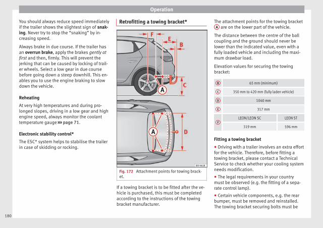
Operation
You should always reduce speed immediatelyif the trailer shows the slightest sign of snak-ing. Never try to stop the “snaking” by in-creasing speed.
Always brake in due course. If the trailer hasan overrun brake, apply the brakes gently atfirst and then, firmly. This will prevent thejerking that can be caused by locking of trail-er wheels. Select a low gear in due coursebefore going down a steep downhill. This en-ables you to use the engine braking to slowdown the vehicle.
Reheating
At very high temperatures and during pro-longed slopes, driving in a low gear and highengine speed, always monitor the coolanttemperature gauge ››› page 71.
Electronic stability control*
The ESC* system helps to stabilise the trailerin case of skidding or rocking.
Retrofitting a towing bracket*
Fig. 172 Attachment points for towing brack-et.
If a towing bracket is to be fitted after the ve-hicle is purchased, this must be completedaccording to the instructions of the towingbracket manufacturer.
The attachment points for the towing bracketA are on the lower part of the vehicle.
The distance between the centre of the ballcoupling and the ground should never belower than the indicated value, even with afully loaded vehicle and including the maxi-mum drawbar load.
Elevation values for securing the towingbracket:
B 65 mm (minimum)
C 350 mm to 420 mm (fully laden vehicle)
D 1040 mm
E 317 mm
FLEON/LEON SC LEON ST
319 mm 596 mm
Fitting a towing bracket
● Driving with a trailer involves an extra effortfor the vehicle. Therefore, before fitting atowing bracket, please contact a TechnicalService to check whether your cooling systemneeds modification.
● The legal requirements in your countrymust be observed (e.g. the fitting of a sepa-rate control lamp).
● Certain vehicle components, e.g. the rearbumper, must be removed and reinstalled.The towing bracket securing bolts must be
180
Towing bracket device
tightened using a torque wrench, and a pow-er socket must be connected to the vehicleelectrical system. This requires specialisedknowledge and tools.
● Figures in the illustration show the eleva-tion value and the attachment points whichmust be considered if you are retrofitting atowing bracket.
WARNING
The towing brackets should be fitted at a spe-cialised workshop.
● If the towing bracket is incorrectly instal-led, there is a serious danger of accident.
● For your own safety, please observe the towbracket manufacturer's instructions.
CAUTION
● If the power socket is incorrectly installed,this could cause damage to the vehicle elec-trical system.
Note
● SEAT recommends that the towing hooksbe fitted at a specialised workshop. Consultyour SEAT dealer in case additional modifica-tions to your vehicle are necessary.
● Due to the specific design of the exhaust,the fitting of a conventional towing hook isnot recommended for some sportier versions.Please consult your Technical Service.
181
Tech
nical
spec
ificati
ons
Adv
ice
Ope
rati
onS
afet
yTh
e es
sent
ials

Advice
Advice
Care and maintenance
Accessories and modificationsto the vehicle
Accessories, replacement parts andrepairs
Always ask your dealer or specialist retailerfor advice before purchasing accessories andreplacement parts.
Your vehicle is designed to offer a highstandard of active and passive safety. For thisreason, we recommend that you ask a SEATOfficial Service for advice before fitting ac-cessories or replacement parts. Your SEAT Of-ficial Service has the latest information fromthe manufacturer and can recommend acces-sories and replacement parts which are suita-ble for your requirements. They can also an-swer any questions you might have regardingofficial regulations.
We recommend you to use only SEAT acces-sories and Genuine SEAT parts®. SEAT hastested these parts and accessories for suita-bility, reliability and safety. SEAT OfficialServices have the necessary experience andfacilities to ensure that the parts are installedcorrectly and professionally.
Any retro-fitted equipment which has a directeffect on the vehicle and/or the way it is driv-en, such as a cruise control system or elec-tronically-controlled suspension, must beapproved for use in your vehicle and bear thee mark (the European Union's authorisationsymbol).
If any additional electrical devices are fittedwhich do not serve to control the vehicle it-self (for instance a refrigerator box, laptop orventilator fan, etc.), they must bear the sign (manufacturer conformity declaration inthe European Union).
WARNING
Accessories, for example telephone holdersor cup holders, should never be fitted on thecovers, or within the working range of the air-bags. Otherwise, there is a danger of injury ifthe airbag is triggered in an accident.
Technical modifications
Modifications must always be carried out ac-cording to our specifications.
Unauthorised modifications to the electroniccomponents, software, wiring or data transferin the vehicle may cause malfunctioning. Dueto the way the electronic components arelinked together in networks, other indirectsystems may be affected by the faults. Thiscan seriously impair safety, lead to excessive
wear of components, and also invalidate yourvehicle registration documents.
You will appreciate that your SEAT dealershipcannot be held liable for any damage causedby modifications and/or work performed in-correctly.
We therefore recommend that all work shouldbe performed by a SEAT Official Service usinggenuine SEAT parts®.
WARNING
Incorrectly performed modifications or otherwork on your vehicle can lead to malfunctionsand cause accidents.
Two-way radios and office equipment
Radio transmitters (fixed installation)
Any retrofit installations of radio transmittersin the vehicle require prior approval. SEATgenerally authorises in-vehicle installationsof approved types of radio transmitters provi-ded that:
● The aerial is installed correctly.
● The aerial is installed on the exterior of thevehicle (and shielded cables are used togeth-er with non-reflective aerial trimming).
● The effective transmitting power does notexceed 10 Watts at the aerial base.
182
Care and maintenance
A SEAT Official Service and specialised work-shop will be able to inform you about optionsfor installing and operating radio transmitterswith a higher transmitting power.
Mobile radio transmitters
Commercial mobile telephones or radioequipment might interfere with the electron-ics of your vehicle and cause malfunctions.This may be due to:
● No external aerial.
● External aerial incorrectly installed.
● Transmitting power more than 10 W.
You must, therefore, do not operate portablemobile telephones or radio equipment insidethe vehicle without a properly installed exter-nal aerial ››› .
Please note also that the maximum range ofthe equipment can only be achieved with anexternal aerial.
Business equipment
Retrofit installation of business or privateequipment in the vehicle is permitted, provi-ded the equipment cannot interfere with thedriver's immediate control of the vehicle andthat any such equipment carries the mark.Any retrofit equipment that could influencethe driver's control of the vehicle must have atype approval for your vehicle and must carrythe e mark.
WARNING
Mobile telephones or radio equipment whichis operated inside the vehicle without a prop-erly installed external aerial can create exces-sive magnetic fields that could cause a healthhazard.
Note
● The posterior fitting of electric and elec-tronic equipment in this vehicle affects its li-cence and could lead to the withdrawal of thevehicle registration document under certaincircumstances.
● Please use the mobile telephone/radio op-erating instructions.
Care and cleaning
General information
Regular and careful care helps to maintainthe value of the vehicle. This may also be oneof the requirements for upholding any war-ranty claims in the event of corrosion or paintdefects.
SEAT Official Services and specialist retailerscarry stocks of suitable car care materials.Please follow the instructions for use on thepackaging.
WARNING
● Cleaning products and other materials usedfor car care can be damaging to your health ifmisused.
● Always keep care products in a safe place,out of the reach of children. Failure to complycould result in poisoning.
For the sake of the environment
● If possible, use environmentally friendlyproducts.
● The remains of car care products should notbe disposed of with ordinary householdwaste.
Vehicle exterior care
Washing the vehicle
The longer substances such as insects, birddroppings, resinous tree sap, road dirt, in-dustrial deposits, tar, soot or road salt andother aggressive materials remain on the ve-hicle, the more damage they do to the paint-work. High temperatures (for instance due tostrong sunlight) further intensify the corro-sive effect.
After the period when salt is put on the roadsit is important to have the underside of thevehicle washed thoroughly. »
183
Tech
nical
spec
ificati
ons
Adv
ice
Ope
rati
onS
afet
yTh
e es
sent
ials
Advice
Automatic car washes
Before going through a car wash, be sure totake the usual precautions such as closingthe windows and roof. If the vehicle has spe-cial accessories such as spoilers or a roofrack or two-way radio aerial, etc., it is advisa-ble to consult the car wash tunnel operator.
It is best to use a car wash without revolvingbristles if possible.
Washing the vehicle with a high pressurecleaner
When washing the vehicle with a high-pres-sure cleaner, always follow the operating in-structions for the equipment. This appliesparticularly to the operating pressure and thespraying distance. Do not hold the nozzle tooclose to soft materials such as rubber hosesor seals. The same applies to the parking aidsensors*, which are located in the rear bump-er.
Do not use a nozzle that sprays the water outin a direct stream or one that has a rotatingjet for forcing off dirt.
Washing the car by hand
When washing the car by hand, use plenty ofwater to soften the dirt first, and rinse off aswell as possible.
Then clean the vehicle with a soft sponge,glove or brush using only slight pressure.You should start on the roof and work down.
Special car soap should only be used for verypersistent dirt.
Rinse the sponge or glove thoroughly and of-ten.
Wheels, sills and similar should be cleanedlast. Use a second sponge for this.
WARNING
● The vehicle should only be washed with theignition switched off. Failure to follow this in-struction could result in an accident.
● Do not clean the underside of chassis, theinside of wheel arches or wheel trims withoutprotecting your hands and arms. You may cutyourself on sharp-edged metal parts. Other-wise, there is a risk of sustaining cuts.
● When washing the car during the winterseason: water and ice in the brake systemcan reduce braking effectiveness: risk of acci-dent!
CAUTION
● Do not wash the vehicle in direct sunlight –otherwise the paint can be damaged.
● Do not use sponges, abrasive householdsponges or similar to clean insect remains.This could damage the surface.
● Clean off stubborn dirt (insects, etc.) fromthe headlights at regular intervals, for in-stance when filling the fuel tank. The head-lights should only be washed with water, do
not wipe them with a dry cloth or sponge. Itis best to use soapy water.
● Never wash tyres with a jet that sprays thewater out in a direct stream. This could dam-age the tyres even if the spray is kept at adistance and only used for a very short time.
● Before washing the vehicle in an automaticcar wash, please make sure to retract the ex-terior mirrors to prevent them from beingdamaged. Electrically retractable exteriormirrors must not be folded in or out by hand,always use the electrical power control.
CAUTION
● Before washing the vehicle in an automaticcar wash, please proceed as follows to lockthe wiper arms so that they are not moved to-wards the top of the windscreen:
– the bonnet must be closed.
– switch the ignition on and off.
– press the windscreen wiper lever forwardbriefly (windscreen washer function).This will lock the wiper arms.
For the sake of the environment
The car should only be washed in specialwash bays. These areas are prepared to pre-vent oily water from getting into the publicdrains. In some places, washing vehicles out-side the areas intended for this purpose isprohibited.
184

Care and maintenance
Camera sensors and lenses
● Use a small brush to remove snow and ade-icer spray to remove ice.
● Clean the sensors with a solvent-free prod-uct and a soft, dry cloth.
● Moisten the camera lens using a standardalcohol-based glass cleaning agent andclean the lens with a dry cloth. In the activelane assist*, the area in front of the lens isnormally cleaned with the windscreen wash-er.
CAUTION
● When you clean the vehicle with a pressurewasher:
– Stay a suitable distance from the sensorson the front and rear bumpers.
– Do not clean the camera lenses or sur-rounding area with the pressure washer.
● Never use warm or hot water to removesnow and ice from the reverse camera lens,as it could crack the lens.
● Never use abrasive cleaning agents on thelens.
Care and polishing
Care
Waxing protects the paintwork. It is time toapply a coat of good wax when water no lon-
ger forms droplets and rolls off the cleanpaintwork.
Even if a wax solution is used regularly in thevehicle washing tunnel, it is advisable to pro-tect the paint with a hard wax coating at leasttwice a year.
In the summer, you will find it is much easierto remove dead insects (which accumulateon the bumper and the front of the bonnet) ifthe car has been treated with care productsrecently.
Polishing
Polishing is only necessary if the paint haslost its shine, and the gloss cannot bebrought back by putting on wax.
If the polish does not contain wax, a waxproduct should be applied after polishing.
CAUTION
● Do not use polishes and hard wax on pain-ted parts with a matt finish or on plasticparts.
● Do not apply paint polishes to the side trimthat runs around the panoramic roof and endson the windscreen. However, it can be treatedwith hard wax.
Trims
In respect for the environment, the silver-plated trims on the body are made of purealuminium (they do not contain chrome).
Dirt or marks on the trim mouldings shouldbe removed with a cleaning product with aneutral PH (do not use a chrome cleaner).Body polish is also unsuitable for use on trimmouldings. The intensive cleaning fluids of-ten used before the car goes into a car washmay contain alkaline substances, which cancause dull or milky patches when they dryout.
SEAT Official Services carry stocks of cleaningproducts which have been tested for use onyour vehicle and are not harmful to the envi-ronment.
Plastic parts
Plastic parts are cleaned with a power wash-er. If this is not sufficient, plastic partsshould only be treated with a special solvent-free plastic cleaning agent. Do not use paint-work cleaners, polishes or wax on plasticparts.
185
Tech
nical
spec
ificati
ons
Adv
ice
Ope
rati
onS
afet
yTh
e es
sent
ials

Advice
Carbon components
The carbon parts on your vehicle have a pain-ted surface. They do not need any specialcare and are cleaned just like any other pain-ted part ››› page 183.
Paint damage
Minor damage to the paint, such as scratchesor stone chips, should be touched up withoutdelay before the metal starts to corrode. Suit-able touch-up brushes or sprays for your carcan be obtained from a SEAT Official Service.
The number of the original paint finish on thevehicle is given on the data sticker››› page 241.
If corrosion is already visible it must be thor-oughly removed by a specialised workshop.
Windows
Clear vision is an essential safety factor.
The windscreen must not be cleaned with in-sect remover or wax, otherwise the wind-screen wipers will not function properly (jud-dering).
Traces of rubber, oil, grease or silicone canbe removed with a window cleaning solutionor a silicone remover. Wax residue can only
be removed with a special cleaner. Your SEATOfficial Service will be able to provide youwith more detailed information.
The windows should also be cleaned on theinside at regular intervals.
Use a separate cloth or chamois to dry thewindows. Cloths used for waxing and polish-ing contain residues that will cause smearson the glass.
WARNING
Do not use water-repellent coatings on thewindscreen. In bad visibility conditions (e.g.in the rain, dark or with a low sun), thesecoatings may cause dazzle: risk of accident!Such coatings can also cause the windscreenwiper blades to make noise.
CAUTION
● Remove snow and ice from windows and ex-terior mirrors with a plastic scraper only. Toavoid scratches caused by dirt on the glass,the scraper should only be pushed in one di-rection and not moved to and fro.
● The heating element for the rear window islocated on the inner side of the window. Toavoid damaging them, do not apply stickersto these heating elements.
● Never use warm or hot water to removesnow and ice from windows and mirrors. Thiscould cause the glass to crack!
Wheels
The wheels require regular attention to pre-serve their appearance. It is important to re-move road salt and brake dust by washingthe wheels at regular intervals, otherwise thefinish will be impaired.
After washing, the wheels should only becleaned with an "acid-free" cleaning agentfor alloy wheels. This is available from SEATOfficial Services and specialist retailers. Nev-er leave the cleaning agent on the rims forany longer than specified in the instructionsbefore rinsing it off. If the wheel cleaner fluidcontains acid it can attack the surfaces of thewheel bolts.
Car polish or other abrasive agents shouldnot be used for maintaining the rims. If theprotective coating is damaged, e.g. by flyingstones, the damaged area should be re-paired immediately.
WARNING
Please note when cleaning the wheels thatwater, ice and road salt can impair the effec-tiveness of the brakes; this can cause an acci-dent.
Exhaust tail pipe
It is important to remove road salt and brakedust by washing the wheels at regular
186
Care and maintenance
intervals, otherwise the exhaust tail pipe ma-terial could be damaged. To remove impuri-ties, do not use rim, paint or chrome cleanersor other abrasive products. Clean the exhausttail pipes with cleaning products that aresuitable for stainless steel.
SEAT Official Services carry stocks of cleaningproducts that have been tested and ap-proved for use on your vehicle.
Care of the vehicle interior
Radio display/Easy Connect* andcontrol panel*
The display can be cleaned with a soft clothand a professionally available “LCD cleaner”.Moisten the cloth with a small amount of thecleaning fluid.
The Easy Connect control panel* should firstbe cleaned with a brush so that no dirt goesinto the device or between the keys andhousing. Next, we recommend cleaning theEasy Connect control panel* using a clothdampened with water and washing-up liquid.
CAUTION
● To avoid scratching the screen, do not wipethe display with a dry cloth.
● To avoid damage, ensure that no liquidgoes into the Easy Connect control panel*.
Plastic and leatherette parts
Plastic parts and leatherette can be cleanedwith a damp cloth. If this is not sufficient,plastic parts and leatherette should only betreated with a special solvent-free plasticcleaner.
Textile covers and trim parts
Textile covers and trim parts (e.g. seats, doortrim) should be cleaned regularly with a vac-uum cleaner. This will remove surface dirtwhich could otherwise be rubbed into thetextile material during use. Do not use steamcleaners, as the steam could carry the dirtdeeper into the textile material.
Normal cleaning
We recommend that you use a soft sponge ora commercially available lint-free, micro-fibrecloth for normal cleaning. Only use brusheson floor coverings and mats, as other textilesurfaces could become damaged.
In the case of normal surface dirt you can usea foam cleaner. Use a sponge to spread thefoam on the textile surface and to work it intothe material lightly. However, make sure thatthe textile material does not become soakingwet. Then dab off the foam with a dry and ab-sorbent cloth (e.g. a micro-fibre cloth) and
vacuum off any residue once the surface iscompletely dry.
Cleaning stains
Treat drink stains (such as coffee or fruitjuice, etc.) with a cleaning solution for deli-cate fabrics. This solution should be appliedwith a sponge. If the stains are difficult to re-move, a washing paste can be applied direct-ly onto the stain and worked into the fabric.The surface will then have to be wiped withclear water to remove any residue left by thepaste. To do so, use a damp cloth or spongeand then dab the stain with an absorbentcloth.
Remove chocolate or make-up stains with acleaning paste (for e.g., soft soap). Then re-move the soap with water (wet sponge).
A spirit-based cleaner can be used to removegrease, oil, lipstick or ball point pen. Thendab the dissolved grease or colour particlesoff with an absorbent cloth or similar. Youmay also have to treat the stain once moreusing washing paste and water.
If the covers or textile trim panels are badlysoiled we recommend that you have themcleaned by a professional cleaning companywith a shampoo and spray. »
187
Tech
nical
spec
ificati
ons
Adv
ice
Ope
rati
onS
afet
yTh
e es
sent
ials

Advice
Note
Open Velcro fasteners on clothes can damagethe seat upholstery. Make sure they areclosed.
Natural leather
General information
Our range of leathers is large. The main typeused is particularly nappa in various forms,that is, leather with a smooth surface in dif-ferent colours.
The amount of dye used determines the ap-pearance and properties of leather. If theleather is left in a more natural state, it re-tains its typical natural napped appearanceand confers excellent all-weather propertiesto the seats. Fine veins, healed scars, insectbites, wrinkles and a subtle variation in shad-ing remain visible; these are the characteris-tic features of genuine natural leather.
Natural napped leather does not have a pro-tective surface coating of dye. It is thereforesomewhat more prone to damage. Thisshould be borne in mind if children or petsoften travel in the car, or if there are otherfactors that could lead to damage.
Types of leather with a coloured surface coat-ing are likely to be more resistant to damage.This has a great advantage for day-to-dayuse. However, this means that the typical
natural characteristics of the surface are lessapparent, though this does not affect quality.
Cleaning and care
Due to the natural properties of the speciallyselected hides employed, the finished leath-er has a certain sensitivity to grease and dirt,etc. so a degree of care is required in every-day use and when looking after the leather.Dark clothing (especially if damp or incorrect-ly dyed) may stain leather upholstery on theseats. Dust and grit in the pores and seamscan scratch and damage the surface. There-fore leather should be cleaned at regular in-tervals, depending on the actual amount ofuse. When they have been in use for a certaintime, your car seats will acquire a typical andunmistakable patina. This is characteristic forleather as a natural product and is a sign ofgenuine quality.
To maintain the value of natural leather youshould note the following points:
CAUTION
● Avoid exposing leather to direct sunlightfor long periods, otherwise it may tend tolose some of its colour. If the car is left for aprolonged period in the bright sun, it is bestto cover the leather.
● Sharp-edged objects on clothing, such asbelts, zip fasteners, rivets or similar, can alsoleave permanent scratches and rough markson the surface of the leather.
Note
● Use a suitable impregnating cream with ul-tra-violet protection at regular intervals andafter cleaning. The cream nourishes andmoisturises the leather, keeps it supple andable to breathe. A protective film will alsoform.
● Clean the leather every 2 to 3 months andremove fresh dirt as soon as possible.
● Remove stains from fresh ball-pen and oth-er inks, lipstick, shoe cream and similarstains as soon as possible.
● Preserve the colour of the leather. A specialcoloured cream will renew the colour of theleather when required and will eliminate dif-ferences in colour.
Cleaning and care of leatherupholstery
Natural leather requires an extra degree of at-tention and care.
Normal cleaning
– Moisten a cotton or woollen cloth with wa-ter and wipe over the leather surfaces.
More stubborn dirt
– More stubborn dirt can be removed using amild soap solution (pure liquid soap: two
188

Care and maintenance
tablespoons dissolved in one litre ofwater).
– Do not let the water soak through the leath-er or penetrate into the seams.
– Then wipe off with a soft, dry cloth.
Removal of stains
– Remove fresh water-based stains such ascoffee, tea, juices, blood etc. with an ab-sorbent cloth or kitchen roll, or use thecleaning agent from the care set for dried-on stains.
– Remove fresh grease-based stains thathave not penetrated the surface such asbutter, mayonnaise, chocolate, etc. with anabsorbent cloth or kitchen roll or with thecleaning agent from the care set.
– Treat fat-based, dried-in stains with grease-dissolving spray.
– Treat less common stains on leather, suchas ball-pen and other inks, felt-tip pens,nail polish, dispersion paint, shoe creametc. with a special leather stain remover.
Leather maintenance
– The leather should be treated regularly(about twice a year) with a special leather-care product.
– Apply these products very sparingly.
– Then wipe off with a soft, dry cloth.
Should you have questions regarding thecare and cleaning of the leather upholstery inyour vehicle, we recommend that you contactyour SEAT Official Service. Our representa-tives will be happy to advise you and tell youabout the product range for leather conserva-tion, for example:
● Cleaning and care set.
● Coloured leather-care cream.
● Stain remover for ball-pen inks, shoe creametc.
● Grease dissolving spray.
● New products and further developments
CAUTION
On no account use solvents (such as petrol,turpentine), wax polish, shoe cream or simi-lar materials.
Cleaning Alcantara upholstery
Removing dust and dirt
– Moisten a cloth just a little and wipe downthe seat covers.
Removing stains
– Moisten a cloth with lukewarm water or di-luted white spirits.
– Dab at the stain. Start at the outside andwork inwards.
– Dry the clean area with a soft cloth.
Do not use leather cleaning products on Al-cantara seat covers.
You may use a suitable soap on dust and dirt.
Dust and grit in the pores and seams canscratch and damage the surface. If the car isleft standing in the sun for long periods, Al-cantara leather should be protected againstdirect sunlight to prevent it from fading. How-ever, slight colour variations will arise in nor-mal use.
CAUTION
● Do not use solvents, wax polish, shoecream, stain removers, leather cleaning prod-ucts or any similar products on Alcantara.
● To avoid damage, stubborn stains shouldbe removed by a specialised workshop.
● On no account use brushes, hard spongesor similar utensils.
Seat belts
– Keep the seat belts clean.
– For cleaning, use a mild solution of soapand water.
– Check the condition of the seat belts at reg-ular intervals. »
189
Tech
nical
spec
ificati
ons
Adv
ice
Ope
rati
onS
afet
yTh
e es
sent
ials
Advice
The retract function may not operate properlyin very dirty belts. Make sure that the inertiareel seat belts are completely dry before al-lowing them to retract.
CAUTION
● Do not remove the seat belts from the vehi-cle to clean them.
● Do not use chemical cleaning agents on theseat belts, as this can damage the webbing.Ensure that the seat belts do not come intocontact with corrosive fluids.
● If you find any damage to the belt webbing,belt fittings, the belt retractor or the buckle,the belt in question must be replaced by aspecialised workshop.
Intelligent technology
Electro-mechanical steering
Electro-mechanical power steering assiststhe driver when steering.
Electro-mechanical power steering adaptselectronically to the speed of the car, torqueand turning angle.
If the power steering should fail at any timeor the engine is switched off (for instancewhen being towed), the car can still besteered. However, more effort than normalwill be required to turn the steering wheel.
Driver warning lamps and messages
(in red) Faulty steering! To park the vehicle
If the warning lamp remains on and the driverindication appears, the power steering couldbe faulty.
Do not continue driving. Seek specialist as-sistance.
(in yellow) Steering: System fault! Youmay continue driving.
If the warning lamp comes on, the steeringcould react with more difficultly or more sen-sitivity than normal. In addition, when drivingin a straight line the steering wheel may beoff-centre.
Drive slowly to a specialised workshop andhave the fault repaired.
(in yellow) Steering lock: fault! Go to anOfficial Service
The electronic steering lock is malfunction-ing.
Go to a specialised workshop as soon aspossible and have the fault repaired.
WARNING
Take it immediately to a specialised work-shop and have the fault repaired: risk of acci-dent!
Note
If the lamp (in red) or else (in yellow)lights up briefly, you may continue driving.
Progressive steering
Depending on the vehicle equipment, theprogressive steering can adapt steering hard-ness to the current driving situation. Thepower steering only works when the engineis running.
In city traffic you do not need to turn so muchon parking, manoeuvring or in very tightturns.
On the road or on the motorway, progressivesteering transmits, for example, in bends, a
190
Intelligent technology
sportier, more direct and noticeably more dy-namic driving sensation.
Four-wheel drive3 Valid for vehicles: with four-wheel drive
On all-wheel drive models, the engine poweris distributed to all four wheels
General notes
On four-wheel drive vehicles, the enginepower is distributed to all four wheels. Thedistribution of power is controlled automati-cally according to your driving style and theroad conditions. Also see ››› page 143, Brak-ing and stability systems.
The all-wheel drive is specially designed tocomplement the superior engine power. Thiscombination gives the vehicle exceptionalhandling and performance capabilities, bothon normal roads and in more difficult condi-tions, such as snow and ice. Even so (or per-haps especially for this reason), it is impor-tant to observe certain safety points ››› .
Winter tyres
Thanks to all-wheel drive, your vehicle willhave plenty of traction in winter conditions,even with the standard tyres. Nevertheless,we still recommend that winter tyres or all-season tyres be fitted on all four wheels togive even better braking response.
Snow chains
On roads where snow chains are mandatory,this also applies to cars with four-wheel drive››› page 216.
Changing tyres
On vehicles with four-wheel drive, all fourtyres must have the same rolling circumfer-ence. Also avoid using tyres with varyingtread depths ››› page 210.
Off-roader?
Your SEAT is not an off-road vehicle: it doesnot have enough ground clearance to beused as such. It is therefore best to avoidrough tracks and uneven terrain as much aspossible.
WARNING
● Even with all-wheel drive, you should al-ways adjust your speed to suit the condi-tions. Do not let the extra safety featurestempt you into taking any risks when driving.Risk of accident!
● The braking capability of your vehicle islimited by the tyres' grip. It is therefore nodifferent from a car without four-wheel drive.So do not be tempted to drive too fast on firmor slippery roads just because the vehiclestill has good acceleration in these condi-tions. Risk of accident!
● On wet roads bear in mind that the frontwheels may start to “aquaplane” and lose
contact with the road if the car is driven toofast. If this should happen, there will be nosudden increase in engine speed to warn thedriver, as occurs with a front-wheel drive car.For this reason you should always choose adriving speed suitable for the road condi-tions. Risk of accident!
Power Management
This system helps to ensure reliablestarting
The power management controls the distribu-tion of electrical energy and thus helps to en-sure that there is always enough power avail-able to start the engine.
If a vehicle with a conventional electrical sys-tem is left parked for a long time, the batterywill gradually lose its charge because certainelectrical devices, such as the electronicgearbox lock continues to draw current evenwhen the ignition is off. In some cases theremay not be enough power available to startthe engine.
Your vehicle is equipped with an intelligentpower management system to control thedistribution of electrical energy. This signifi-cantly improves reliability when starting theengine, and also prolongs the useful life ofthe battery. »
191
Tech
nical
spec
ificati
ons
Adv
ice
Ope
rati
onS
afet
yTh
e es
sent
ials
Advice
The main functions incorporated in the powermanagement system are battery diagnosis,residual current management and dynamicpower management.
Battery diagnosis
The battery diagnosis function constantlyregisters the condition of the battery. Sen-sors detect the battery voltage, battery cur-rent and battery temperature. This enablesthe system to calculate the current power lev-el and charge condition of the battery.
Residual current management
The residual current management reducespower consumption while the vehicle isparked. It controls the supply of power to thevarious electrical devices while the ignition isswitched off. The system takes the battery di-agnosis data into consideration.
Depending on the power level of the battery,switch off the individual electrical devicesone after the other to prevent the batteryfrom losing too much charge and to ensurethat the engine can be started reliably.
Dynamic power management
While the vehicle is moving, this function dis-tributes the available power to the variouselectrical devices and systems according totheir requirements. The power managementensures that on-board systems do not con-
sume more electrical power than the alterna-tor can supply, and thus maintains the maxi-mum possible battery power level.
Note
● Neither is the power management systemable to overcome the given physical limits.Please remember that the power and usefullife of the battery are limited.
● When there is a risk that the vehicle willnot start, the alternator power failure or lowbattery charge level warning lamp will beshown ››› page 71.
Flat battery
Starting ability has first priority.
Short trips, city traffic and low temperaturesall place a heavy load on the battery. In theseconditions a large amount of power is con-sumed, but only a small amount is supplied.The situation is also critical if electrical devi-ces are in use when the engine is not run-ning. In this case power is consumed whennone is being generated.
In these situations you will be aware that thepower management system is intervening tocontrol the distribution of electrical power.
When the vehicle is parked for long periods
If you do not drive your vehicle for a period ofseveral days or weeks, the power manage-ment will gradually shut off the electrical de-vices one by one or reduce the amount of cur-rent they are using. This limits the amount ofpower consumed and helps to ensure relia-ble starting even after a long period. Someconvenience functions, such as remote vehi-cle opening, may not be available under cer-tain circumstances. These functions will berestored when you switch on the ignition andstart the engine.
With the engine switched off
For example, if you listen to the sound sys-tem with the engine switched off the batterywill run down.
If the energy consumption means there is arisk that the engine will not start, a text willappear in vehicles with a driver informationsystem*.
This driver indicator tells you that you muststart the engine so that the battery can re-charge.
When the engine is running
Although the alternator generates electricalpower, the battery can still become dis-charged while the vehicle is being driven.This can occur when a lot of power is beingconsumed but only a small amount supplied,
192

Checking and refilling levels
especially if the battery is not fully chargedinitially.
To restore the necessary energy balance, thesystem will then temporarily shut off the elec-trical devices that are using a lot of power, orreduce the current they are consuming. Heat-ing systems in particular use a large amountof electrical power. If you notice, for instance,that the seat heating* or the rear windowheater is not working, they may have beentemporarily switched off or regulated to alower heat output. These systems will beavailable again as soon as sufficient electri-cal power is available.
You may also notice that the engine runs at aslightly faster idling speed when necessary.This is quite normal, and no cause for con-cern. The increased idling speed allows thealternator to meet the greater power require-ment and charge the battery at the sametime.
Checking and refilling levels
Refuelling
Filling the tank
Read the additional information carefully››› page 31
If the automatic filler nozzle is operated cor-rectly, it will switch itself off as soon as thefuel tank is “full”. Do not try to put in morefuel after the nozzle cuts out, as this will fillthe expansion chamber in the fuel tank.
The correct fuel grade for your vehicle is giv-en on a sticker on the inside of the fuel tankflap. Further notes on fuel can be found at››› page 195.
The capacity of the fuel tank is listed in thevehicle technical specifications ››› page 268.
WARNING
Fuel is highly flammable and can cause seri-ous burns and other injuries.
● Do not smoke when filling the fuel tank or acanister. Naked flames are forbidden in thevicinity due to the risk of explosion.
● Observe legislation governing the use,storage and carrying of a spare fuel canisterin the vehicle.
● For safety reasons we do not recommendcarrying a spare fuel canister in the vehicle.
In an accident the canister could be damagedand could leak.
● If, in exceptional circumstances, you haveto carry a spare fuel canister, please observethe following points:
– Never fill fuel into the spare fuel canisterif it is inside or on top of the vehicle. Anelectrostatic charge could build up duringfilling, causing the fuel vapour to ignite.Danger of explosion. Always place thecanister on the ground to fill it.
– Insert the filling nozzle as far as possibleinto the spare fuel canister.
– If the spare fuel canister is made of met-al, the filling nozzle must be in contactwith the canister during filling. Thishelps prevent an electrostatic chargebuilding up.
– Never spill fuel in the vehicle or in theluggage compartment. Fuel vapour is ex-plosive. Risk of fatal accident!
CAUTION
● If any fuel is spilt onto the vehicle, itshould be removed immediately. It could oth-erwise damage the paintwork.
● Never run the tank completely dry. An irreg-ular fuel supply could cause misfiring. As aresult, unburnt fuel could enter the exhaustsystem and damage the catalytic converter.
● When filling the fuel tank after having run itcompletely dry on a vehicle with a diesel en-gine, the ignition must be switched on for at »
193
Tech
nical
spec
ificati
ons
Adv
ice
Ope
rati
onS
afet
yTh
e es
sent
ials

Advice
least 30 seconds before starting the engine.When you then start the engine it may takelonger than normal (up to one minute) tostart firing. This is because air needs to bebled from the fuel system while starting.
For the sake of the environment
Do not overfill the fuel tank, it may cause thefuel to overflow if it becomes warm.
Note
Diesel vehicles are fitted with a protective de-vice that prevents the insertion of the wrongfuel hose1). It is only possible to refuel withDiesel nozzles.
● If the pump nozzle is worn, damaged, or ifit is very small, it is possible that it will notbe able to open the protective device. Beforetrying to insert the pump nozzle by turning it,try a different pump or request specialisthelp.
● If you fill the tank from a reserve fuel canis-ter, the protective device will not open. Oneway to resolve this is to pour the fuel in veryslowly.
Refuelling with natural gas
Fig. 173 Tank flap open: gas filler mouth 1 ,filler mouth retainer 2
Before refuelling, the engine and the igni-tion, mobile telephone and heating must beswitched off separately ››› .
Read the instructions on how to use the natu-ral gas pump carefully.
The vehicle is not prepared for refuelling withliquefied natural gas (LNG) ››› . Before refu-elling with natural gas, make sure you addthe appropriate type of fuel ››› page 195.
Opening the fuel tank cap
The natural gas filler mouth is behind the fueltank cap, next to the petrol filler mouth.
● Unlock the vehicle with the key or with thecentral locking button situated on the driv-er door ››› page 82.
● Press on the rear area of the flap and openit.
Refuelling
Things to note: if the ambient temperature isvery high, the natural gas pump protectionagainst overheating disconnects this auto-matically.
● Remove the plug from the gas filler mouth››› Fig. 173 1 .
● Connect the pump filling nozzle to the gasfiller mouth.
● The fuel tank will be full when the pumpcompressor automatically cuts the supply.
● If you wish to finish refuelling in advance,press the button on the pump to stop theflow.
Closing the fuel tank cap
● Check that the gas filler mouth retainer 2
is not trapped with the filler nozzle. If neces-sary, place it in the filler mouth again.
● Insert the plug in the filler mouth.
● Close the tank flap. Make sure you hear itclick into place.
1) Depending on country194
Checking and refilling levels
WARNING
Natural gas is a highly explosive, easily flam-mable substance. Incorrect handling of thenatural gas can cause accidents seriousburns and other injuries.
● Before refuelling with natural gas, engagethe filling mouth correctly. If you can smellgas, stop refuelling immediately.
WARNING
The vehicle is not prepared to use liquefiednatural gas (LNG), and this fuel must not beadded under any circumstances. Liquefiednatural gas can cause the natural gas tank toexplode, resulting in serious injury.
Note
● The filling nozzles of natural gas pumpscan differ in the way they are operated. If youdo not know, ask a qualified employee at thepetrol station to do the refuelling.
● Noises heard when refuelling are normaland do not indicate the presence of a fault inthe system.
● The vehicle natural gas system is preparedboth for refuelling with a small compressor(slow refuel) and a large compressor (fast re-fuel) in natural gas service stations.
Fuel
Types of petrol
The correct grade of petrol is listed inside thefuel tank flap.
The vehicle is equipped with a catalytic con-verter and must only be run on unleaded pet-rol. The petrol must comply with EuropeanStandard EN 228 or German standard DIN51626-1 and must be unleaded. You can re-fuel with a maximum ethanol proportion of10 % (E10). The types of petrol are differenti-ated by their octane rating (RON).
The following titles appear on the corre-sponding adhesive on the fuel tank flap:
Super unleaded 95 octane or normal 91octane unleaded petrol
We recommend you use super 95 octane pet-rol. If this is not available: normal 91 octanepetrol, with a slight decrease in power.
Super unleaded petrol with a minimum of 95octanes
You should use super petrol with a minimumof 95 octanes.
If super is not available, in an emergency youmay refuel with normal 91 octane petrol. Inthis case only use moderate engine speedsand a light throttle. Refuel with super as soonas possible.
Super unleaded 98 octane or super 95octane unleaded petrol
We recommend you use super plus 98 octanepetrol. If this is not available: super 95 oc-tane petrol, with a slight decrease in power.
If super is not available, in an emergency youmay refuel with normal 91 octane petrol. Inthis case only use moderate engine speedsand a light throttle. Refuel with super as soonas possible.
Petrol additives
The quality of the fuel influences the behav-iour, power and service life of the engine.This is why the petrol you use should carrysuitable additives already included by thepetrol industry, free of metals. These addi-tives will help to prevent corrosion, keep thefuel system clean and prevent deposits frombuilding up in the engine.
If good-quality petrol with metal-free addi-tives is not available or engine problemsarise, the necessary additives must be addedwhen refuelling ››› .
Not all petrol additives have been shown tobe effective. The use of unsuitable petrol ad-ditives may cause significant damage to theengine and the catalytic converter. Metal ad-ditives should never be used. Metal additivesmay also be contained in petrol additives forimproving anti-detonation ratings or octaneratings ››› . »
195
Tech
nical
spec
ificati
ons
Adv
ice
Ope
rati
onS
afet
yTh
e es
sent
ials

Advice
SEAT recommends “genuine VolkswagenGroup Fuel Additives for petrol engines”.These additives can be bought at SEAT deal-ers, where information on how to use themcan also be obtained.
CAUTION
● Do not refuel if the filler indicates that thefuel contains metal. LRP (lead replacementpetrol) fuels contain high concentrations ofmetal additives. Using them may damage theengine!
● Never refuel with fuels containing a largeproportion of ethanol (for example, E50, E85).This could damage the fuel system.
● Just filling one full tank of leaded fuel orfuel containing other metal additives wouldseriously impair the efficiency of the catalyticconverter.
● Only use fuel additives that have been ap-proved by SEAT. Octane boosting or anti-knock additives may contain metal additivesthat could seriously damage the engine orthe catalytic converter. These additives mustnot be used.
● High engine speed and full throttle candamage the engine when using petrol with anoctane rating lower than the correct grade forthe engine.
Note
● You may use petrol with a high octane num-ber than the one recommended for your en-gine.
● In those countries where unleaded petrol isnot available, you may refuel with a fuel witha low lead content.
Diesel Fuel
Please note the information on the inside ofthe fuel tank flap.
We recommend the use of diesel fuel whichcomplies to European standard EN 590. Ifdiesel fuel which meets European standardEN 590 is not available, the Cetane number(CZ) must, at minimum, be 51. If the engineis equipped with a particulate filter, the sul-phur content of the fuel must be below 50parts per million.
Winter-grade diesel
Summer fuel becomes thicker in winter and itis more difficult to start the engine. For thisreason, petrol stations in some countries al-so offer winter diesel with improved fluiditywhen cold (winter-grade diesel).
Water in the fuel filter1)
If your vehicle has a diesel engine and isequipped with a fuel filter with a water sepa-rator, the instrument panel may display the
following warning: Water in the fuel filter.If this is the case, take the vehicle to a speci-alised workshop so that they can drain thefuel filter.
CAUTION
● The vehicle is not designed for the use ofFAME fuel (biodiesel). The fuel system wouldbe damaged if you used biodiesel.
● Do not mix fuel additives, the so-called“thinners”, petrol or similar additives withdiesel fuel.
● If poor-quality diesel fuel is used, it may benecessary to drain the fuel filter more fre-quently than is specified in the MaintenanceProgramme. We recommend having this doneby a specialised workshop. If water is allowedto collect in the filter, this can cause engineperformance problems.
Natural gas
Natural gas
Natural gas can be compressed or in liquidform, addition to others.
1) Valid for the market: Algeria.196

Checking and refilling levels
Liquefied natural gas (LNG) is the result ofheavy cooling of natural gas. Therefore itsvolume is considerably reduced comparedwith compressed natural gas (CNG). In vehi-cles with a natural gas engine, liquefied nat-ural gas cannot be directly refilled, as the gaswould expand excessively in the vehicle gastank.
Therefore, vehicles with a natural gas enginemust only be refuelled using compressednatural gas ››› .
Natural gas quality and consumption
Natural gas is divided into the groups H andL depending on its quality.
Gas type H has a superior heating power andinferior nitrogen and carbon dioxide contentthan type L. The higher the heating power ofthe natural gas, the lower the consumptionwill be.
However, the heating power and the propor-tion of nitrogen and carbon dioxide can fluc-tuate within the quality groups. Therefore, ve-hicle consumption can also vary when usinga single type of gas only.
The engine management automaticallyadapts to the natural gas used according toits quality. Therefore, different quality gasescan be mixed in the tank, without the needfor comprehensive draining before applying adifferent quality gas.
Updated information relating to natural gasquality is displayed on the instrument panel››› page 72.
Natural gas and safety
If you can smell gas or suspect that there is aleak ››› :
● Stop the vehicle immediately.
● Switch the ignition off.
● Open the doors to appropriately ventilatethe vehicle.
● Extinguish cigarettes immediately.
● Move away from the vehicle or switch offobjects that may cause sparks or a fire.
● If you continue to smell gas, do not contin-ue driving!
● Seek specialist assistance. Have the faultrepaired.
WARNING
Failure to act when you can smell gas in thevehicle or when refuelling can cause seriousinjuries.
● Carry out the necessary operations.
● Leave the danger zone.
● If necessary, warn the emergency services.
WARNING
The vehicle is not prepared to use liquefiednatural gas (LNG) and this fuel must not beadded under any circumstances. Liquefiednatural gas can cause the natural gas tank toexplode, resulting in serious injury.
Note
Have the natural gas system checked regular-ly by a specialised workshop, according tothe Maintenance Programme.
197
Tech
nical
spec
ificati
ons
Adv
ice
Ope
rati
onS
afet
yTh
e es
sent
ials
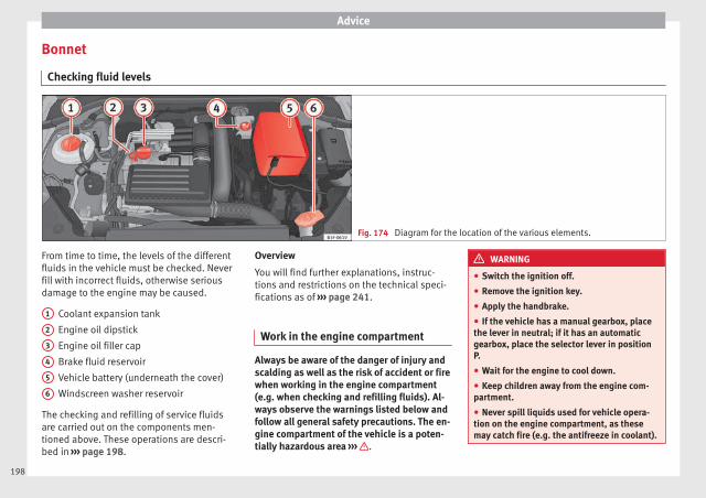
Advice
Bonnet
Checking fluid levels
Fig. 174 Diagram for the location of the various elements.
From time to time, the levels of the differentfluids in the vehicle must be checked. Neverfill with incorrect fluids, otherwise seriousdamage to the engine may be caused.
Coolant expansion tank
Engine oil dipstick
Engine oil filler cap
Brake fluid reservoir
Vehicle battery (underneath the cover)
Windscreen washer reservoir
The checking and refilling of service fluidsare carried out on the components men-tioned above. These operations are descri-bed in ››› page 198.
1
2
3
4
5
6
Overview
You will find further explanations, instruc-tions and restrictions on the technical speci-fications as of ››› page 241.
Work in the engine compartment
Always be aware of the danger of injury andscalding as well as the risk of accident or firewhen working in the engine compartment(e.g. when checking and refilling fluids). Al-ways observe the warnings listed below andfollow all general safety precautions. The en-gine compartment of the vehicle is a poten-tially hazardous area ››› .
WARNING
● Switch the ignition off.
● Remove the ignition key.
● Apply the handbrake.
● If the vehicle has a manual gearbox, placethe lever in neutral; if it has an automaticgearbox, place the selector lever in positionP.
● Wait for the engine to cool down.
● Keep children away from the engine com-partment.
● Never spill liquids used for vehicle opera-tion on the engine compartment, as thesemay catch fire (e.g. the antifreeze in coolant).
198

Checking and refilling levels
● Take care not to cause short circuits in theelectrical system, especially when workingon the battery.
● If working inside the engine compartment,remember that, even when the ignition isswitched off, the radiator fan may start up au-tomatically, and therefore there is a risk of in-jury.
● Never cover the engine with additional in-sulating materials such as a blanket. Risk offire!
● Do not unscrew the cap on the coolant ex-pansion tank when the engine is hot. Thecooling system is under pressure.
● Protect face, hands and arms by coveringthe cap with a large, thick rag to protectagainst escaping coolant and steam.
● If it is necessary to work in the engine com-partment while the engine is running, the ro-tating components (for example, poly-V belt,alternator, radiator fan) and the high voltageignition system are an additional hazard.
● Observe the following additional warningsif work on the fuel system or the electricalsystem is necessary:
– Always disconnect the battery from theon-board network.
– Do not smoke.
– Never work near naked flames.
– Always keep an approved fire extinguish-er immediately available.
CAUTION
When topping up fluids make sure the correctfluid is put into the correct filler opening, oth-erwise this can cause serious malfunctions orengine damage.
For the sake of the environment
Inspect the ground underneath your vehicleregularly so that any leaks are detected at anearly stage. If you find spots of oil or otherfluids in the area where it was parked, haveyour vehicle inspected at the workshop.
Note
On right-hand drive vehicles* some of thecontainers/reservoirs mentioned below arelocated on the other side of the engine com-partment.
Opening the bonnet
Read the additional information carefully››› page 10
The bonnet is released from inside the vehi-cle.
Check that the windscreen wiper arms arenot unfolded. Otherwise the paint may bedamaged.
The bonnet can only be unlocked when thedriver door is open.
WARNING
Never open the bonnet if you see steam ordrips of coolant being released from the en-gine compartment. Failure to comply couldresult in burns. Wait until no steam or coolantcan be seen before opening the bonnet.
Closing the bonnet
– Slightly lift the bonnet.
– Release the bonnet stay before pressing itback into its support.
– Carefully close the bonnet.
– Press the bonnet down until it locks intoplace.
– Make sure that the bonnet catches onto itsclasp. Do not press down too hard ››› .
WARNING
● For safety reasons the bonnet must alwaysbe completely closed when the vehicle ismoving. Therefore, after closing the bonnet,always check that the locking element isproperly engaged. This is the case if the bon-net is flush with the adjacent body panels.
● Should you notice that the bonnet is notsafely secured when the vehicle is moving,stop the vehicle immediately and close thebonnet. Failure to follow this instructioncould result in an accident.
199
Tech
nical
spec
ificati
ons
Adv
ice
Ope
rati
onS
afet
yTh
e es
sent
ials

Advice
Engine oil
General notes
The engine comes with a special, multi-gradeoil that can be used all year round.
Because the use of high-quality oil is essen-tial for the correct operation of the engineand its long useful life, when topping up orchanging oil, use only those oils that complywith VW standards.
The specifications (VW standards) set out inthe following page should appear on the con-tainer of the service oil; when the containerdisplays the specific standards for petrol anddiesel engines together, it means that the oilcan be used for both types of engines.
We recommend that the oil change indicatedin the Maintenance Programme, be per-formed by a technical service or specialisedworkshop.
The correct oil specifications for your engineare listed in the ››› page 201, Oil properties.
Service intervals
Service intervals can be flexible (LongLifeservice) or fixed (dependent on time/dis-tance travelled).
If the PR code that appears on the back of theMaintenance Programme booklet is PR QI6,this means that your vehicle has the LongLife
service programmed. If it lists the codes QI1,QI2, QI3, QI4 or QI7, the interval service isdependent on time/distance travelled.
Flexible service intervals (LongLife serviceintervals*)
Special oils and processes have been devel-oped which, depending on the characteris-tics and individual driving profiles, enablethe extension of the oil change service (Long-Life service intervals).
Because this oil is essential for extending theservice intervals, it must only be used ob-serving the following indications:
● Avoid mixing it with oil for fixed service in-tervals.
● Only in exceptional circumstances, if theengine oil level is too low ››› page 201 andLongLife oil is not available, it is permitted totop up (once) with oil for fixed service inter-vals ››› page 201 (up to a maximum of 0.5 li-tres).
Fixed service intervals*
If your vehicle does not have the “LongLifeservice interval” or it has been disabled (byrequest), you may use oils for fixed serviceintervals, which also appear in ››› page 201,Oil properties. In this case, your vehicle mustbe serviced after a fixed interval of 1year/15,000 km (10,000 miles)(whatever
comes first) ››› Booklet Maintenance Pro-gramme.
● In exceptional circumstances, if the engineoil level is too low ››› page 201 and you can-not obtain the oil specified for your vehicle,you can add a small quantity of oil conform-ing to the specification ACEA A2 or ACEA A3(petrol engines) or ACEA B3 or ACEA B4 (die-sel engines) (up to 0.5 l).
Vehicles with diesel particulate filter*
The Maintenance Programme states whetheryour vehicle is fitted with a diesel particulatefilter.
Only VW 507 00 engine oil, with reduced ashformation, may be used in diesel enginesequipped with particulate filter. Using othertypes of oil will cause a higher soot concen-tration and reduce the life of the DPF. There-fore:
● Avoid mixing this oil with other engine oils.
● Only in exceptional circumstances, if theengine oil level is too low ››› page 201 andyou cannot obtain the oil specified for yourvehicle, you can use a small quantity of oil(once) conforming to the VW 506 00,VW 506 01, VW 505 00, VW 505 01 orACEA B3/ACEA B4 specification. (up to 0.5 l).
200
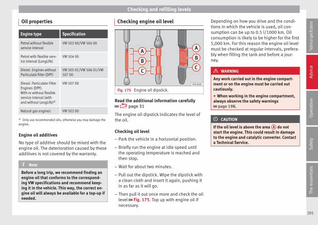
Checking and refilling levels
Oil properties
Engine type Specification
Petrol without flexibleservice interval
VW 502 00/VW 504 00
Petrol with flexible serv-ice interval (LongLife)
VW 504 00
Diesel. Engines withoutParticulate filter (DPF)
VW 505 01/VW 506 01/VW507 00
Diesel. Particulate FilterEngines (DPF).With or without flexibleservice interval (withand without LongLife)a)
VW 507 00
Natural gas engines VW 502 00
a) Only use recommended oils, otherwise you may damage theengine.
Engine oil additives
No type of additive should be mixed with theengine oil. The deterioration caused by theseadditives is not covered by the warranty.
Note
Before a long trip, we recommend finding anengine oil that conforms to the correspond-ing VW specifications and recommend keep-ing it in the vehicle. This way, the correct en-gine oil will always be available for a top-up ifneeded.
Checking engine oil level
Fig. 175 Engine oil dipstick.
Read the additional information carefully››› page 31
The engine oil dipstick indicates the level ofthe oil.
Checking oil level
– Park the vehicle in a horizontal position.
– Briefly run the engine at idle speed untilthe operating temperature is reached andthen stop.
– Wait for about two minutes.
– Pull out the dipstick. Wipe the dipstick witha clean cloth and insert it again, pushing itin as far as it will go.
– Then pull it out once more and check the oillevel ››› Fig. 175. Top up with engine oil ifnecessary.
Depending on how you drive and the condi-tions in which the vehicle is used, oil con-sumption can be up to 0.5 l/1000 km. Oilconsumption is likely to be higher for the first5,000 km. For this reason the engine oil levelmust be checked at regular intervals, prefera-bly when filling the tank and before a jour-ney.
WARNING
Any work carried out in the engine compart-ment or on the engine must be carried outcautiously.
● When working in the engine compartment,always observe the safety warnings››› page 198.
CAUTION
If the oil level is above the area A do notstart the engine. This could result in damageto the engine and catalytic converter. Contacta Technical Service.
201
Tech
nical
spec
ificati
ons
Adv
ice
Ope
rati
onS
afet
yTh
e es
sent
ials
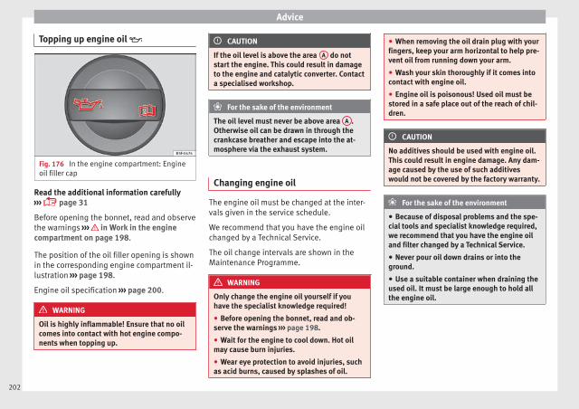
Advice
Topping up engine oil
Fig. 176 In the engine compartment: Engineoil filler cap
Read the additional information carefully››› page 31
Before opening the bonnet, read and observethe warnings ››› in Work in the enginecompartment on page 198.
The position of the oil filler opening is shownin the corresponding engine compartment il-lustration ››› page 198.
Engine oil specification ››› page 200.
WARNING
Oil is highly inflammable! Ensure that no oilcomes into contact with hot engine compo-nents when topping up.
CAUTION
If the oil level is above the area A do notstart the engine. This could result in damageto the engine and catalytic converter. Contacta specialised workshop.
For the sake of the environment
The oil level must never be above area A .Otherwise oil can be drawn in through thecrankcase breather and escape into the at-mosphere via the exhaust system.
Changing engine oil
The engine oil must be changed at the inter-vals given in the service schedule.
We recommend that you have the engine oilchanged by a Technical Service.
The oil change intervals are shown in theMaintenance Programme.
WARNING
Only change the engine oil yourself if youhave the specialist knowledge required!
● Before opening the bonnet, read and ob-serve the warnings ››› page 198.
● Wait for the engine to cool down. Hot oilmay cause burn injuries.
● Wear eye protection to avoid injuries, suchas acid burns, caused by splashes of oil.
● When removing the oil drain plug with yourfingers, keep your arm horizontal to help pre-vent oil from running down your arm.
● Wash your skin thoroughly if it comes intocontact with engine oil.
● Engine oil is poisonous! Used oil must bestored in a safe place out of the reach of chil-dren.
CAUTION
No additives should be used with engine oil.This could result in engine damage. Any dam-age caused by the use of such additiveswould not be covered by the factory warranty.
For the sake of the environment
● Because of disposal problems and the spe-cial tools and specialist knowledge required,we recommend that you have the engine oiland filter changed by a Technical Service.
● Never pour oil down drains or into theground.
● Use a suitable container when draining theused oil. It must be large enough to hold allthe engine oil.
202
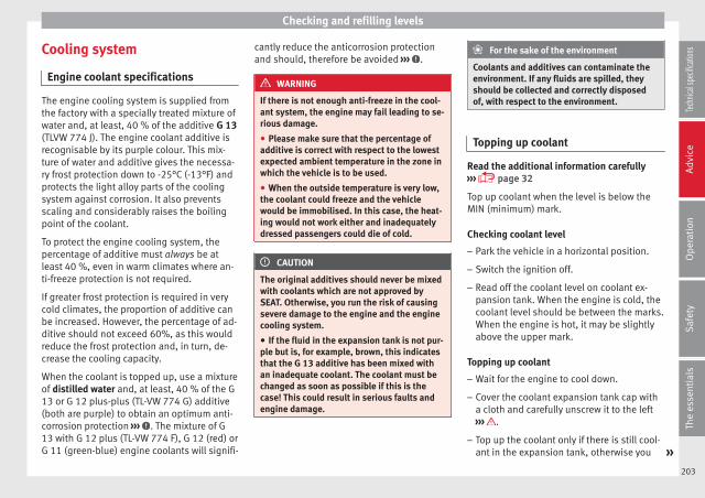
Checking and refilling levels
Cooling system
Engine coolant specifications
The engine cooling system is supplied fromthe factory with a specially treated mixture ofwater and, at least, 40 % of the additive G 13(TLVW 774 J). The engine coolant additive isrecognisable by its purple colour. This mix-ture of water and additive gives the necessa-ry frost protection down to -25°C (-13°F) andprotects the light alloy parts of the coolingsystem against corrosion. It also preventsscaling and considerably raises the boilingpoint of the coolant.
To protect the engine cooling system, thepercentage of additive must always be atleast 40 %, even in warm climates where an-ti-freeze protection is not required.
If greater frost protection is required in verycold climates, the proportion of additive canbe increased. However, the percentage of ad-ditive should not exceed 60%, as this wouldreduce the frost protection and, in turn, de-crease the cooling capacity.
When the coolant is topped up, use a mixtureof distilled water and, at least, 40 % of the G13 or G 12 plus-plus (TL-VW 774 G) additive(both are purple) to obtain an optimum anti-corrosion protection ››› . The mixture of G13 with G 12 plus (TL-VW 774 F), G 12 (red) orG 11 (green-blue) engine coolants will signifi-
cantly reduce the anticorrosion protectionand should, therefore be avoided ››› .
WARNING
If there is not enough anti-freeze in the cool-ant system, the engine may fail leading to se-rious damage.
● Please make sure that the percentage ofadditive is correct with respect to the lowestexpected ambient temperature in the zone inwhich the vehicle is to be used.
● When the outside temperature is very low,the coolant could freeze and the vehiclewould be immobilised. In this case, the heat-ing would not work either and inadequatelydressed passengers could die of cold.
CAUTION
The original additives should never be mixedwith coolants which are not approved bySEAT. Otherwise, you run the risk of causingsevere damage to the engine and the enginecooling system.
● If the fluid in the expansion tank is not pur-ple but is, for example, brown, this indicatesthat the G 13 additive has been mixed withan inadequate coolant. The coolant must bechanged as soon as possible if this is thecase! This could result in serious faults andengine damage.
For the sake of the environment
Coolants and additives can contaminate theenvironment. If any fluids are spilled, theyshould be collected and correctly disposedof, with respect to the environment.
Topping up coolant
Read the additional information carefully››› page 32
Top up coolant when the level is below theMIN (minimum) mark.
Checking coolant level
– Park the vehicle in a horizontal position.
– Switch the ignition off.
– Read off the coolant level on coolant ex-pansion tank. When the engine is cold, thecoolant level should be between the marks.When the engine is hot, it may be slightlyabove the upper mark.
Topping up coolant
– Wait for the engine to cool down.
– Cover the coolant expansion tank cap witha cloth and carefully unscrew it to the left››› .
– Top up the coolant only if there is still cool-ant in the expansion tank, otherwise you »
203
Tech
nical
spec
ificati
ons
Adv
ice
Ope
rati
onS
afet
yTh
e es
sent
ials
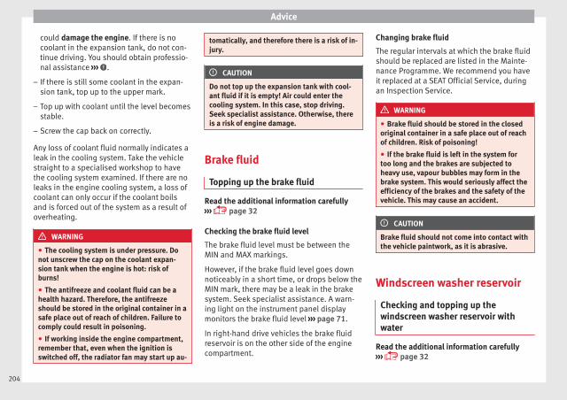
Advice
could damage the engine. If there is nocoolant in the expansion tank, do not con-tinue driving. You should obtain professio-nal assistance ››› .
– If there is still some coolant in the expan-sion tank, top up to the upper mark.
– Top up with coolant until the level becomesstable.
– Screw the cap back on correctly.
Any loss of coolant fluid normally indicates aleak in the cooling system. Take the vehiclestraight to a specialised workshop to havethe cooling system examined. If there are noleaks in the engine cooling system, a loss ofcoolant can only occur if the coolant boilsand is forced out of the system as a result ofoverheating.
WARNING
● The cooling system is under pressure. Donot unscrew the cap on the coolant expan-sion tank when the engine is hot: risk ofburns!
● The antifreeze and coolant fluid can be ahealth hazard. Therefore, the antifreezeshould be stored in the original container in asafe place out of reach of children. Failure tocomply could result in poisoning.
● If working inside the engine compartment,remember that, even when the ignition isswitched off, the radiator fan may start up au-
tomatically, and therefore there is a risk of in-jury.
CAUTION
Do not top up the expansion tank with cool-ant fluid if it is empty! Air could enter thecooling system. In this case, stop driving.Seek specialist assistance. Otherwise, thereis a risk of engine damage.
Brake fluid
Topping up the brake fluid
Read the additional information carefully››› page 32
Checking the brake fluid level
The brake fluid level must be between theMIN and MAX markings.
However, if the brake fluid level goes downnoticeably in a short time, or drops below theMIN mark, there may be a leak in the brakesystem. Seek specialist assistance. A warn-ing light on the instrument panel displaymonitors the brake fluid level ››› page 71.
In right-hand drive vehicles the brake fluidreservoir is on the other side of the enginecompartment.
Changing brake fluid
The regular intervals at which the brake fluidshould be replaced are listed in the Mainte-nance Programme. We recommend you haveit replaced at a SEAT Official Service, duringan Inspection Service.
WARNING
● Brake fluid should be stored in the closedoriginal container in a safe place out of reachof children. Risk of poisoning!
● If the brake fluid is left in the system fortoo long and the brakes are subjected toheavy use, vapour bubbles may form in thebrake system. This would seriously affect theefficiency of the brakes and the safety of thevehicle. This may cause an accident.
CAUTION
Brake fluid should not come into contact withthe vehicle paintwork, as it is abrasive.
Windscreen washer reservoir
Checking and topping up thewindscreen washer reservoir withwater
Read the additional information carefully››› page 32
204
Checking and refilling levels
Check the water level in the windscreenwasher reservoir regularly and top up as re-quired.
The container for the windscreen washer con-tains the cleaning fluid for the windscreen,the rear window and the headlight washersystem*.
● Open the bonnet ››› page 198.
● The windscreen washer reservoir is markedwith the symbol on the cap.
● Check there is enough windscreen water inthe reservoir.
Recommended windscreen wipers
● For the hottest seasons we recommendsummer G 052 184 A1 for clear glass. Propor-tions of the mixture in the washer fluid tank:1:100 (1 part concentrate per 100 parts wa-ter).
● All year round, G 052 164 A2 for clearglass. Approximate proportion of the wintermixture, up to -18°C (0°F): 1:2 (1 part con-centrate per 2 parts water); otherwise, a 1:4proportion of mixture in the washer fluidtank.
Top-up quantities
The reservoir holds approximately 3 litres inversions without headlight washer and 5 li-tres in versions with headlight washer.
WARNING
If the water from the windscreen washer doesnot contain enough anti-freeze, it may freezeon the windscreen and rear window, reducingforward and rear visibility.
● In winter, ensure the windscreen washercontains enough anti-freeze.
● In cold conditions, you should not use thewindscreen washer system unless you havewarmed the windscreen with the ventilationsystem. The antifreeze could freeze on thewindscreen and reduce visibility.
WARNING
Never mix an unsuitable antifreeze or othersimilar additives with the windscreen washerwater. A greasy layer may be formed on thewindscreen which will impair visibility.
● Use clean water with a window cleaner rec-ommended by SEAT.
● If necessary, add a suitable antifreeze tothe water in the reservoir.
CAUTION
● Do not mix cleaning products recommen-ded by SEAT with other products. This couldlead to flocculation and may block the wind-screen washer jets.
● When topping up service fluids, make abso-lutely certain that you fill the fluids into thecorrect reservoirs. Using the wrong fluids
could cause serious malfunctions and enginedamage!
● Not having windscreen wiper fluid reducesvisibility through the windscreen, and leadsto loss of visibility in headlights in modelswith headlight washer.
Battery
General information
The battery is located in the engine compart-ment and is almost maintenance-free. It ischecked as part of the Inspection Service.Nevertheless, check the terminals are cleanand have the correct tightening torque, espe-cially in summer and winter.
Disconnecting the battery
The battery should only be disconnected inexceptional cases. When the battery is dis-connected, some of the vehicle's functionsare “lost” (››› table on page 206). Thesefunctions will require resetting after the bat-tery is reconnected.
Deactivate the anti-theft alarm* before youdisconnect the battery Otherwise the alarmwill be triggered. »
205
Tech
nical
spec
ificati
ons
Adv
ice
Ope
rati
onS
afet
yTh
e es
sent
ials
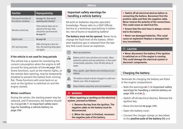
Advice
Function Reprogramming
One-touch function ofthe electric windows
››› page 92, One-touchopening and closing*.
Remote control key
If the vehicle does not re-spond to the key, theyshould be synchronised››› page 87.
Digital clock ››› page 68.
ESC warning lampAfter driving for a few me-tres, the warning lamp goesout again.
If the vehicle is not used for long periods
The vehicle has a system for monitoring thecurrent consumption when the engine is leftunused for long periods of time ››› page 191.Some functions, such as the interior lights, orthe remote door opening, may be temporarilydisabled to prevent the battery from runningflat. These functions will come back on assoon as the ignition is switched on and theengine started.
Winter conditions
During the winter, the starting power may bereduced, and if necessary, the battery shouldbe charged ››› in Important safety warn-ings for handling a vehicle battery onpage 206
Important safety warnings forhandling a vehicle battery
All work on batteries requires specialistknowledge. Please refer to a SEAT OfficialService or a workshop specialising in batter-ies: risk of burns or exploding battery!
The battery must not be opened. Never try tochange the fluid level of the battery. Other-wise explosive gas is released from the bat-tery that could cause an explosion.
Wear eye protection.
Battery acid is very corrosive and caustic. Wearprotective gloves and eye protection. In the eventof electrolyte splashes, rinse off with plenty ofwater.
Fires, sparks, open flames and smoking are pro-hibited.
The battery should only be charged in a well-ven-tilated zone. Risk of explosion!
Keep children away from acid and batteries!
WARNING
● When repairing or working on the electricalsystem, proceed as follows:
– 1. Remove the key from the ignition. Thenegative cable on the battery must bedisconnected.
– 2. When the repair is finished, reconnectthe negative pole of the battery.
● Switch off all electrical devices before re-connecting the battery. Reconnect first thepositive cable and then the negative cable.Never reverse the polarity of the connections.This could cause an electrical fire.
● Ensure that the vent hose is always connec-ted to the battery.
● Never use damaged batteries. This couldcause an explosion! Replace a damaged bat-tery immediately.
CAUTION
● Never disconnect the battery if the ignitionis switched on or if the engine is running.This could damage the electrical system orelectronic components.
Charging the battery
Terminals for charging the battery are fittedin the engine compartment.
– Note the warnings ››› in Important safetywarnings for handling a vehicle battery onpage 206 and ››› .
– Switch off all electrical devices. Remove theignition key.
– Raise the bonnet ››› page 199.
– Open the battery cover.
– Connect the charger clamps as describedto the positive pole of the battery (+) and
206

Checking and refilling levels
exclusively to an earth on the bodywork(–).
– Only use a charger which is compatible foruse with 12 V nominal voltage batteries.The charge must not exceed a voltage of 15V.
– Now connect the battery charger to thepower socket and switch on.
– After charging the battery: switch off thebattery charger and disconnect the powersocket cable.
– Finally disconnect the charger cables fromthe battery.
– Replace the battery cover correctly.
– Close the bonnet ››› page 199.
Important: Before you charge the batterymake sure you read the manufacturer's in-structions for using the battery charger.
WARNING
Never charge a battery that has frozen: re-place battery! Failure to do so may lead to anexplosion.
Note
Use only the terminals in the engine compart-ment to charge the battery.
Replacing the battery
The new battery should have the same speci-fications (amperage, load and voltage) as theused battery.
Your vehicle is equipped with an intelligentpower management system to control thedistribution of electrical energy ››› page 191.The power management function ensuresthat the battery is charged much more effi-ciently than on vehicles without a powermanagement system. To maintain this func-tion after replacing the battery, we recom-mend that the replacement battery used is ofthe same make and type as the original fittedbattery. To make proper use of the powermanagement function after the battery hasbeen changed, have the battery coded to thepower management mode at a specialisedworkshop.
CAUTION
● Some vehicles, for example those with theStart-Stop system* are fitted with a specialbattery (AGM-type or EFB-type battery). If anyother type of battery is fitted, the Start-Stopfunction may be considerably reduced andthe vehicle may not stop on repeated occa-sions.
● Make sure that the vent hose is always at-tached to the original opening on the side ofthe battery. Gases or battery acid can other-wise escape and possibly cause damage.
● The battery holder and clamps must alwaysbe correctly secured.
● Before starting any work on the battery, al-ways observe the warnings listed under››› page 206, Important safety warnings forhandling a vehicle battery.
● Do not forget to replace the battery cover-ings, where applicable. It is a protection forhigh temperatures. This in turn extends thevehicle service life.
For the sake of the environment
Batteries contain toxic substances includ-ing sulphuric acid and lead. They must bedisposed of appropriately and must not bedisposed of with ordinary household waste.Make sure disconnected batteries cannot tipover. Sulphuric acid could be spilt!
207
Tech
nical
spec
ificati
ons
Adv
ice
Ope
rati
onS
afet
yTh
e es
sent
ials

Advice
Wheels
Wheels and tyres
General notes
– When driving with new tyres, be especiallycareful during the first 500 km (300 miles).
– If you have to drive over a kerb or similarobstacle, drive very slowly and as near aspossible at a right angle to the obstacle.
– Check from time to time if the tyres aredamaged (punctures, cuts, cracks ordents). Remove any foreign objects embed-ded in the treads.
– Damaged wheels and tyres must be re-placed immediately.
– Keep grease, oil and fuel off the tyres.
– Replace any missing valve caps as soon aspossible.
– Mark the wheels before taking them off sothat they rotate in the same direction whenput back.
– When removed, the wheels or tyres shouldbe stored in a cool, dry and preferably darkplace.
New tyres
New tyres do not give maximum grip straightaway and should therefore be “run in” by
driving carefully and at moderate speeds forabout the first 500 km (300 miles). This willalso increase the useful life of the tyres.
The tread depth of new tyres may vary, ac-cording to the type and make of tyre and thetread pattern.
Concealed damage
Damage to tyres and rims is often not readilyvisible. If you notice unusual vibration or thecar pulling to one side, this may indicate thatone of the tyres is damaged. Reduce speedimmediately if there is any reason to suspectthat damage may have occurred. Inspect thetyres for damage. If no external damage isvisible, drive slowly and carefully to the near-est specialised workshop and have the carinspected.
Tyres with directional tread pattern
An arrow on the tyre sidewall indicates the di-rection of rotation on single drive tyres. Al-ways note the direction of rotation indicatedwhen mounting the wheel. This guaranteesoptimum grip and helps to avoid aquaplan-ing, excessive noise and wear.
Retrofitting Accessories
If you wish to change or fit wheels, rims orwheel trims, we recommend that you consultwith a SEAT Official Service centre for adviceregarding current techniques.
Useful life of tyres
Correct inflation pressures and sensible driv-ing habits will increase the useful life of yourtyres.
– Check tyre pressure at least once a month,and also prior to any long trip.
– The tyre pressure should only be checkedwhen the tyres are cold. Do not reduce thepressure of warm tyres.
– Adjust tyre pressure to the load being car-ried by the vehicle.
– In vehicles with a tyre pressure indicator,save the pressure of modified tyres››› page 212, ››› page 208.
– Avoid fast cornering and hard acceleration.
– Inspect the tyres for irregular wear fromtime to time.
The useful life of your tyres depends on thefollowing factors:
Tyre pressure
Tyre pressure values are indicated on thesticker on the inside of the fuel tank flap.
Insufficient or excessive pressure greatly re-duces the useful life of the tyres and adverse-ly affects vehicle performance and ride. Cor-rect inflation pressures are very important,especially at high speeds.
208

Wheels
Depending on the vehicle, tyre pressure canbe adjusted (“comfort” tyre pressure) to in-crease driving comfort. When driving withcomfort tyre pressure fuel consumption mayincrease slightly.
The tyre pressure must be adjusted accordingto the load the vehicle is carrying. If the vehi-cle is going to carry the maximum load, thetyre pressure should be increased to maxi-mum value indicated on the sticker on the in-side of the fuel tank flap.
Do not forget the spare wheel when checkingthe tyre pressures: Keep this spare wheel in-flated to the highest pressure required for theroad wheels.
In the case of a minimised temporary sparewheel (125/70 R16 or 125/70 R18) inflate toa pressure of 4.2 bar as indicated on the tyrepressure label on the fuel tank flap.
Driving style
Fast cornering, heavy acceleration and hardbraking (squealing tyres) all increase tyrewear.
Wheel balance
The wheels on new vehicles are balanced.However, certain circumstances may lead toimbalance (run-out), which is detected as vi-brations in the steering wheel.
Unbalanced wheels should be rebalanced, asthey otherwise cause excessive wear onsteering, suspension and tyres. A wheel mustalso be rebalanced when a new tyre is fittedor if a tyre is repaired.
Incorrect wheel alignment
Incorrect wheel alignment causes excessivetyre wear, impairing the safety of the vehicle.If you notice excessive tyre wear, you shouldcheck wheel alignment at a SEAT OfficialService.
WARNING
● Always adapt the tyre pressure accordinglywhen the vehicle load changes.
● A tyre with low air pressure has to flex a lotmore when the vehicle is heavily loaded or athigh speeds, therefore causing overheatingto occur. Under these conditions, the tyrebead may be released or the tyre may burst.Risk of accident!
For the sake of the environment
Under-inflated tyres will increase fuel con-sumption.
Wear indicators
Fig. 177 Tyre tread: tread wear indicators
Tread wear indicators indicate if a tyre isworn.
The original tyres on your vehicle have1.6 mm high “tread wear indicators” runningacross the tread. Depending on the manufac-turer, there will be 6 to 8 of them spaced atequal distances around the tyre. Markings onthe tyre sidewall (for instance the letters“TWI” or a triangle) indicate the positions ofthe tread wear indicators.
The minimum tread depth required by law is1.6 mm (measured in the tread grooves nextto the tread wear indicators). (Different fig-ures may apply in other countries.) »
209
Tech
nical
spec
ificati
ons
Adv
ice
Ope
rati
onS
afet
yTh
e es
sent
ials

Advice
WARNING
The tyres must be replaced at the latest whenthe tread is worn down to the tread wear indi-cators. Failure to follow this instruction couldresult in an accident.
● Especially in difficult driving conditionssuch as wet or icy roads. It is important thatthe tyre tread be as deep as possible and beapproximately the same on the tyres of boththe front and the rear axles.
● The scant driving safety due to insufficienttread depth is particularly evident in vehiclehandling, when there is a risk of “aquaplan-ing” in deep puddles of water and when driv-ing through corners, and braking is also ad-versely affected.
● The speed has to be adapted accordingly,otherwise there is a risk of losing control overthe vehicle.
Changing wheels
Fig. 178 Interchanging tyres.
To ensure that the wear is equal on all tyresthe wheels should be changed round fromtime to time according to the system››› Fig. 178. The useful life of all the tyres willthen be about the same time.
Replacing wheels and tyres
– All four wheels must be fitted with tyres ofthe same type, size (rolling circumference)and preferably the same tread pattern.
– Tyres should be replaced at least in pairsand not individually (i.e. both front tyres orboth rear tyres together).
– Do not use tyres whose effective size ex-ceeds the dimensions of the factory-ap-proved makes of tyre.
– If you wish to fit the vehicle with rims ortyres different to those installed in manu-facture, it is advisable to consult a SEAT Of-ficial Service before purchasing them.
The tyres and wheel rims are an essentialpart of the vehicle's design. The tyres andrims approved by SEAT are specially matchedto the characteristics of the vehicle and makea major contribution to good roadholdingand safe handling ››› .
The sizes of the rims and tyres approved foryour vehicle are listed in the vehicle docu-mentation (e.g. EC Certificate of Conformity orCOC document1)). The vehicle documentationvaries depending on the country of resi-dence.
Note for Italy: A SEAT Service Centre shouldbe consulted whether different sized wheelsor tyres to those originally fitted by SEAT maybe fitted, as well as the combinations al-lowed between the front axle (axle 1) andback axle (axle 2).
A knowledge of tyre designations makes iteasier to choose the correct tyres. The follow-ing wording can be read on the sides of thetyre:
1) COC = certificate of conformity.210
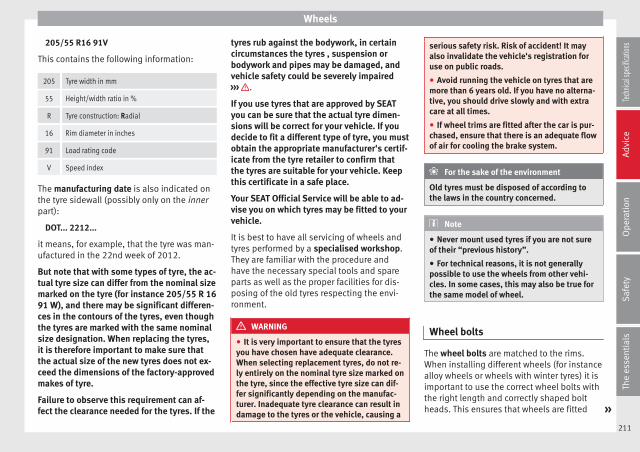
Wheels
205/55 R16 91V
This contains the following information:
205 Tyre width in mm
55 Height/width ratio in %
R Tyre construction: Radial
16 Rim diameter in inches
91 Load rating code
V Speed index
The manufacturing date is also indicated onthe tyre sidewall (possibly only on the innerpart):
DOT... 2212...
it means, for example, that the tyre was man-ufactured in the 22nd week of 2012.
But note that with some types of tyre, the ac-tual tyre size can differ from the nominal sizemarked on the tyre (for instance 205/55 R 1691 W), and there may be significant differen-ces in the contours of the tyres, even thoughthe tyres are marked with the same nominalsize designation. When replacing the tyres,it is therefore important to make sure thatthe actual size of the new tyres does not ex-ceed the dimensions of the factory-approvedmakes of tyre.
Failure to observe this requirement can af-fect the clearance needed for the tyres. If the
tyres rub against the bodywork, in certaincircumstances the tyres , suspension orbodywork and pipes may be damaged, andvehicle safety could be severely impaired››› .
If you use tyres that are approved by SEATyou can be sure that the actual tyre dimen-sions will be correct for your vehicle. If youdecide to fit a different type of tyre, you mustobtain the appropriate manufacturer's certif-icate from the tyre retailer to confirm thatthe tyres are suitable for your vehicle. Keepthis certificate in a safe place.
Your SEAT Official Service will be able to ad-vise you on which tyres may be fitted to yourvehicle.
It is best to have all servicing of wheels andtyres performed by a specialised workshop.They are familiar with the procedure andhave the necessary special tools and spareparts as well as the proper facilities for dis-posing of the old tyres respecting the envi-ronment.
WARNING
● It is very important to ensure that the tyresyou have chosen have adequate clearance.When selecting replacement tyres, do not re-ly entirely on the nominal tyre size marked onthe tyre, since the effective tyre size can dif-fer significantly depending on the manufac-turer. Inadequate tyre clearance can result indamage to the tyres or the vehicle, causing a
serious safety risk. Risk of accident! It mayalso invalidate the vehicle's registration foruse on public roads.
● Avoid running the vehicle on tyres that aremore than 6 years old. If you have no alterna-tive, you should drive slowly and with extracare at all times.
● If wheel trims are fitted after the car is pur-chased, ensure that there is an adequate flowof air for cooling the brake system.
For the sake of the environment
Old tyres must be disposed of according tothe laws in the country concerned.
Note
● Never mount used tyres if you are not sureof their “previous history”.
● For technical reasons, it is not generallypossible to use the wheels from other vehi-cles. In some cases, this may also be true forthe same model of wheel.
Wheel bolts
The wheel bolts are matched to the rims.When installing different wheels (for instancealloy wheels or wheels with winter tyres) it isimportant to use the correct wheel bolts withthe right length and correctly shaped boltheads. This ensures that wheels are fitted »
211
Tech
nical
spec
ificati
ons
Adv
ice
Ope
rati
onS
afet
yTh
e es
sent
ials

Advice
securely and that the brake system functionscorrectly.
The wheel bolts must be clean and turn easi-ly.
A special adapter is required to turn the anti-theft wheel bolts* ››› page 218.
Tyre monitoring systems
Introduction
WARNING
Unsuitable handling of the wheels and tyresmay lead to sudden tyre pressure losses, totread separation or even to a blow-out.
● Check tyre pressures regularly and ensurethey are maintained at the pressures indica-ted. Tyre pressure that is too low could causeoverheating, resulting in tread detachment oreven burst tyres.
● Tyre pressure should be that indicated onthe label when the tyres are cold at all times››› page 243.
● Regularly check the cold inflation pressureof the tyres. If necessary, change the tyrepressure of the vehicle tyres while they arecold.
● Regularly check your tyres for damage andwear.
● Never exceed the maximum permittedspeed or loads specified for the type of tyrefitted on your vehicle.
For the sake of the environment
Under-inflated tyres lead to increased fuelconsumption and tyre wear.
Note
● Driving for the first time with new tyres at ahigh speed can cause them to slightly ex-pand, which could then produce an air pres-sure warning.
● Only replace used tyres with those author-ised by SEAT for the corresponding type vehi-cle.
● Do not only rely on the tyre monitoring sys-tem. Regularly check your tyres to ensurethat the tyre pressure is correct and that thetyres are not damaged due to puncture, cuts,tears and impacts/dents. Remove objectsfrom the tyres only when they have notpierced the tyres.
Tyre monitor indicator warning lamp
If a light appears
The pressure in one or more tyres hasclearly reduced in comparison to thetyre pressure set by the driver or thetyre has structural damage.
Additionally, an audible warning can be heard and a textmessage can be seen on the instrument panel display.Stop the vehicle! Reduce speed immediately! Stopthe vehicle safely as soon as possible. Avoid suddenmanoeuvres and braking! Check all tyres and pressures.Replace any damaged tyres.
If flashing
System malfunction
The control lamp flashes for approximately one minuteand then lights up permanently.If tyre pressure is correct, switch the ignition off and onagain. If the control lamp remains lit up, the tyre moni-toring indicator can be calibrated. Have the systemchecked by a specialised workshop.
Several warning and control lamps light upfor a few seconds when the ignition is switch-ed on while the function is verified. They willswitch off after a few seconds.
WARNING
When the tyres are inflated at different pres-sures or at a pressure that is too low then atyre may be damaged resulting in a loss of
212
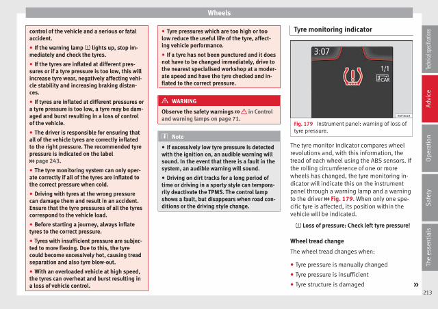
Wheels
control of the vehicle and a serious or fatalaccident.
● If the warning lamp lights up, stop im-mediately and check the tyres.
● If the tyres are inflated at different pres-sures or if a tyre pressure is too low, this willincrease tyre wear, negatively affecting vehi-cle stability and increasing braking distan-ces.
● If tyres are inflated at different pressures ora tyre pressure is too low, a tyre may be dam-aged and burst resulting in a loss of controlof the vehicle.
● The driver is responsible for ensuring thatall of the vehicle tyres are correctly inflatedto the right pressure. The recommended tyrepressure is indicated on the label››› page 243.
● The tyre monitoring system can only oper-ate correctly if all of the tyres are inflated tothe correct pressure when cold.
● Driving with tyres at the wrong pressurecan damage them and result in an accident.Ensure that the tyre pressures of all the tyrescorrespond to the vehicle load.
● Before starting a journey, always inflatetyres to the correct pressure.
● Tyres with insufficient pressure are subjec-ted to more flexing. Due to this, the tyrecould become excessively hot, causing treadseparation and also tyre blow-out.
● With an overloaded vehicle at high speed,the tyres can overheat and burst resulting ina loss of vehicle control.
● Tyre pressures which are too high or toolow reduce the useful life of the tyre, affect-ing vehicle performance.
● If a tyre has not been punctured and it doesnot have to be changed immediately, drive tothe nearest specialised workshop at a moder-ate speed and have the tyre checked and in-flated to the correct pressure.
WARNING
Observe the safety warnings ››› in Controland warning lamps on page 71.
Note
● If excessively low tyre pressure is detectedwith the ignition on, an audible warning willsound. In the event that there is a fault in thesystem, an audible warning will sound.
● Driving on dirt tracks for a long period oftime or driving in a sporty style can tempora-rily deactivate the TPMS. The control lampshows a fault, but disappears when road con-ditions or the driving style change.
Tyre monitoring indicator
Fig. 179 Instrument panel: warning of loss oftyre pressure.
The tyre monitor indicator compares wheelrevolutions and, with this information, thetread of each wheel using the ABS sensors. Ifthe rolling circumference of one or morewheels has changed, the tyre monitoring in-dicator will indicate this on the instrumentpanel through a warning lamp and a warningto the driver ››› Fig. 179. When only one spe-cific tyre is affected, its position within thevehicle will be indicated.
Loss of pressure: Check left tyre pressure!
Wheel tread change
The wheel tread changes when:
● Tyre pressure is manually changed
● Tyre pressure is insufficient
● Tyre structure is damaged »213
Tech
nical
spec
ificati
ons
Adv
ice
Ope
rati
onS
afet
yTh
e es
sent
ials

Advice
● The vehicle is unbalanced because of aload
● The wheels on an axle are subject to aheavier load (e.g. with a heavy load).
● The vehicle is fitted with snow chains
● The temporary spare wheel is fitted
● The wheel on one axle is changed
There may be a delay in the reaction of thetyre monitoring indicator or it may not in-dicate anything under certain circumstances(e.g. sporty driving, snow-covered or un-paved roads, or when driving with snowchains).
Calibrating the tyre monitoringindicator
Fig. 180 Glove compartment: tyre controlswitch.
After changing the tyre pressure or replacingone or more wheels, the tyre monitoring indi-cator must be recalibrated. Do the same, forexample, when the front and rear wheels areswapped.
● Switch the ignition on.
● Store the new tyre pressure in the EasyConnect system with the button and thefunction button Setup ››› page 17 or us-ing the switch located in the glove compart-ment* ››› Fig. 180.
When driving, the system self-calibrates thetyre pressure provided by the driver and thewheels fitted. After a long journey with variedspeeds the programmed values are collectedand monitored.
With the wheels under very heavy loads, thetyre pressure must be increased to the totalrecommended tyre pressure before the cali-bration ››› page 243.
Note
● The tyre monitoring indicator does notfunction when there is a fault in the ESC orABS ››› page 143.
● An erroneous indication may be given whensnow chains are in use because they increasethe tread of the wheel.
Compact temporary sparewheel
General information
Fig. 181 Compact temporary spare wheel:raised floor panel.
The temporary spare wheel has been de-signed to be used for short periods of time.Have the tyres checked, and if necessary, re-placed as soon as possible at a SEAT OfficialService or at a specialised workshop.
Please note the following restrictions whenusing the compact temporary spare wheel.The compact temporary spare wheel is de-signed specifically for this model. For thisreason, do not use a temporary spare wheelfrom a different type of vehicle.
214
Wheels
Removing the temporary spare wheel
– Lift and hold up the floor panel to removethe temporary spare wheel ››› Fig. 181.
– Turn the thumb wheel anti-clockwise.
– Take out the temporary spare wheel.
Chains
For technical reasons, snow chains must notbe used on the temporary spare wheel.
If you have a puncture on one of the frontwheels when using snow chains, fit the tem-porary spare wheel in place of one of the rearwheels. Fit the snow chains on the rear wheelthat you have removed and replace the punc-tured front wheel with this wheel.
WARNING
● After fitting the temporary spare wheel,check the tyre pressures as soon as possible.Failure to do so may cause an accident. Thetyre pressures are listed on the inside of thefuel tank flap.
● Do not drive at over 80 km/h (50 mph)when the temporary spare wheel is fitted onthe vehicle: risk of accident!
● Avoid heavy acceleration, hard braking andfast cornering: risk of accident!
● Never use more than one temporary sparewheel at the same time, risk of accident.
● No other type of tyre (normal summer orwinter tyre) may be fitted on the compacttemporary spare wheel rim.
● If you are driving using the spare wheel,the ACC system could automatically switchoff during the journey. Switch off the systemwhen starting off.
Extraction of the spare wheel invehicles with SEAT SOUND 10speakers (with subwoofer)*
– Disassemble the subwoofer's floor panel(carpet) as follows:
– LEON/LEON SC model: first, pull the carpetin the direction of the backrest and thenpull it upwards to remove it. LEON ST mod-el: lift and secure the floor storage com-partment as explained in ››› page 121.
– Disconnect the subwoofer's speaker cable.
– Turn the securing wheel anti-clockwise.
– Remove the subwoofer speaker and thespare wheel.
– When replacing the spare wheel, place thesubwoofer speaker in the direction indica-ted by the arrow and with the word“FRONT” facing forward.
– Reconnect the speaker cable and firmly ro-tate the securing wheel clockwise so that
the subwoofer system and wheel are firmlyin place.
Winter service
Winter tyres
– Winter tyres must be fitted on all fourwheels.
– Only use winter tyres that are approved foryour vehicle.
– Please note that the maximum permissiblespeed for winter tyres may be lower thanfor summer tyres.
– Also note that winter tyres are no longer ef-fective when the tread is worn down.
– After fitting the wheels you must alwayscheck the tyre pressures. The correct tyrepressures are listed on the sticker on theinside of the fuel tank flap ››› page 208.
In winter road conditions winter tyres willconsiderably improve vehicle handling. Thedesign of summer tyres (width, rubber com-pound, tread pattern) gives less grip on iceand snow. This applies particularly to vehi-cles equipped with wide section tyres or withhigh speed tyres (code letters H, V or Y onthe sidewall). »
215
Tech
nical
spec
ificati
ons
Adv
ice
Ope
rati
onS
afet
yTh
e es
sent
ials

Advice
Only use winter tyres of the correct type ap-proved for your vehicle. The sizes of thesetyres are specified in the vehicle's docu-ments (e.g. EC Certificate of Conformity orCOC1)). The vehicle documentation varies de-pending on the country of residence. See al-so ››› page 210.
Winter tyres lose a great deal of their proper-ties when the tread is worn down to a depthof 4 mm.
The performance of winter tyres is also se-verely impaired by ageing, even if the tread isstill much deeper than 4 mm.
Winter tyres are subject to the following max-imum speed limits according to speed ratingcode letter: ›››
Speed ratingcode letter››› page 210
Maximum speed limit
Q 160 km/h
S 180 km/h
T 190 km/h
H 210 km/h
V240 km/h (150 mph)(note restrictions)
W 270 km/h
Speed ratingcode letter››› page 210
Maximum speed limit
Y 300 km/h
Vehicles capable of exceeding these speedsmust have an appropriate sticker attached sothat it is visible to the driver. Suitable stickersare available from the SEAT Official Serviceand specialised workshop. Please note theregulations to this effect in your country.
“All-weather” tyres can also be used insteadof winter tyres.
Using winter tyres with V-rating
Please note that the generally applicable240 km/h (150 mph) speed rating for wintertyres with the letter V is subject to technicalrestrictions; the maximum permissiblespeed for your vehicle may be significantlylower. The maximum speed limit for thesetyres depends directly on the maximum axleweights for your car and on the listed weightrating of the tyres being used.
It is best to contact a SEAT Official Service tocheck the maximum speed which is permissi-ble for the V-rated tyres fitted on your car onthe basis of this information.
WARNING
Exceeding the maximum speed permitted forthe winter tyres fitted on your car can causetyre failure, resulting in a loss of control ofthe vehicle – risk of accident.
For the sake of the environment
Summer tyres should be fitted again as soonas possible after the winter period; they givebetter handling on roads which are free ofsnow and ice. Summer tyres perform withless rolling noise, tyre wear and – most im-portant – reduce fuel consumption.
Snow chains
– Snow chains can be used on the frontwheels only.
– Check that they are correctly seated afterdriving for a few yards; correct the positionif necessary. Always take the manufacturerassembly instructions into account.
– Keep your speed below 50 km/h.
– If there is a danger of being trapped de-spite having mounted the chains, it is bestto disable the driving wheels (ASR) in theESC ››› page 145, Switching on/off the ESCand ASR.
1) COC = certificate of conformity.216
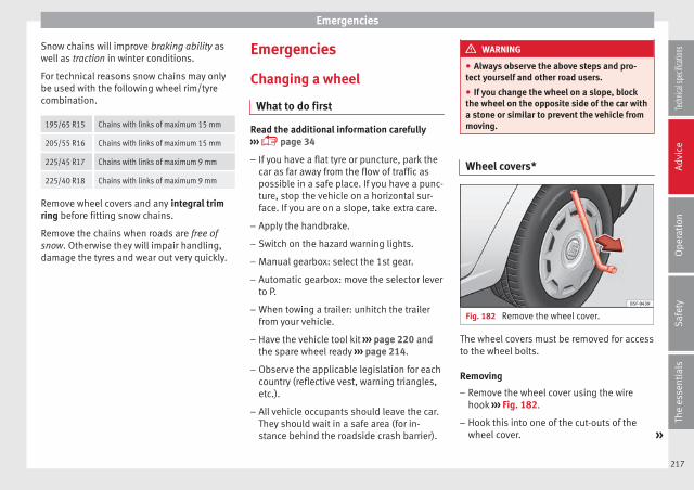
Emergencies
Snow chains will improve braking ability aswell as traction in winter conditions.
For technical reasons snow chains may onlybe used with the following wheel rim/tyrecombination.
195/65 R15 Chains with links of maximum 15 mm
205/55 R16 Chains with links of maximum 15 mm
225/45 R17 Chains with links of maximum 9 mm
225/40 R18 Chains with links of maximum 9 mm
Remove wheel covers and any integral trimring before fitting snow chains.
Remove the chains when roads are free ofsnow. Otherwise they will impair handling,damage the tyres and wear out very quickly.
Emergencies
Changing a wheel
What to do first
Read the additional information carefully››› page 34
– If you have a flat tyre or puncture, park thecar as far away from the flow of traffic aspossible in a safe place. If you have a punc-ture, stop the vehicle on a horizontal sur-face. If you are on a slope, take extra care.
– Apply the handbrake.
– Switch on the hazard warning lights.
– Manual gearbox: select the 1st gear.
– Automatic gearbox: move the selector leverto P.
– When towing a trailer: unhitch the trailerfrom your vehicle.
– Have the vehicle tool kit ››› page 220 andthe spare wheel ready ››› page 214.
– Observe the applicable legislation for eachcountry (reflective vest, warning triangles,etc.).
– All vehicle occupants should leave the car.They should wait in a safe area (for in-stance behind the roadside crash barrier).
WARNING
● Always observe the above steps and pro-tect yourself and other road users.
● If you change the wheel on a slope, blockthe wheel on the opposite side of the car witha stone or similar to prevent the vehicle frommoving.
Wheel covers*
Fig. 182 Remove the wheel cover.
The wheel covers must be removed for accessto the wheel bolts.
Removing
– Remove the wheel cover using the wirehook ››› Fig. 182.
– Hook this into one of the cut-outs of thewheel cover. »
217
Tech
nical
spec
ificati
ons
Adv
ice
Ope
rati
onS
afet
yTh
e es
sent
ials
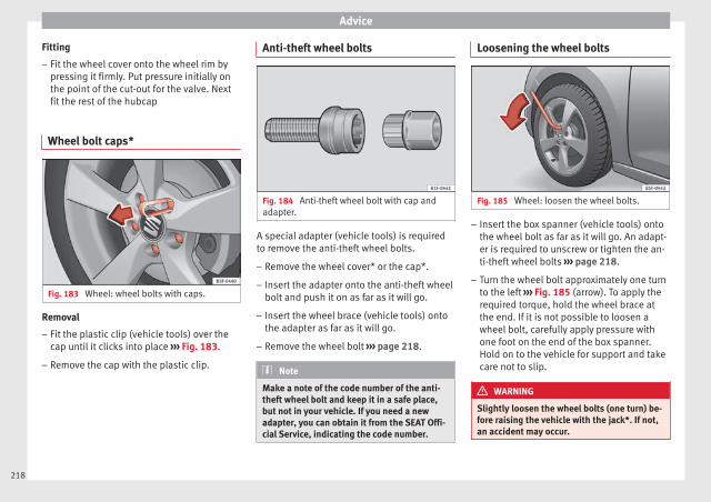
Advice
Fitting
– Fit the wheel cover onto the wheel rim bypressing it firmly. Put pressure initially onthe point of the cut-out for the valve. Nextfit the rest of the hubcap
Wheel bolt caps*
Fig. 183 Wheel: wheel bolts with caps.
Removal
– Fit the plastic clip (vehicle tools) over thecap until it clicks into place ››› Fig. 183.
– Remove the cap with the plastic clip.
Anti-theft wheel bolts
Fig. 184 Anti-theft wheel bolt with cap andadapter.
A special adapter (vehicle tools) is requiredto remove the anti-theft wheel bolts.
– Remove the wheel cover* or the cap*.
– Insert the adapter onto the anti-theft wheelbolt and push it on as far as it will go.
– Insert the wheel brace (vehicle tools) ontothe adapter as far as it will go.
– Remove the wheel bolt ››› page 218.
Note
Make a note of the code number of the anti-theft wheel bolt and keep it in a safe place,but not in your vehicle. If you need a newadapter, you can obtain it from the SEAT Offi-cial Service, indicating the code number.
Loosening the wheel bolts
Fig. 185 Wheel: loosen the wheel bolts.
– Insert the box spanner (vehicle tools) ontothe wheel bolt as far as it will go. An adapt-er is required to unscrew or tighten the an-ti-theft wheel bolts ››› page 218.
– Turn the wheel bolt approximately one turnto the left ››› Fig. 185 (arrow). To apply therequired torque, hold the wheel brace atthe end. If it is not possible to loosen awheel bolt, carefully apply pressure withone foot on the end of the box spanner.Hold on to the vehicle for support and takecare not to slip.
WARNING
Slightly loosen the wheel bolts (one turn) be-fore raising the vehicle with the jack*. If not,an accident may occur.
218

Emergencies
Raising the vehicle
Fig. 186 Crossbar: marks.
Fig. 187 Strut: mounting the jack on the vehi-cle.
– Place the jack* (vehicle tools) on a firm sur-face. If necessary use a large, strong boardor similar support. On a slippery surface(such as tiles) place the jack on a rubbermat or similar to prevent it from slipping.››› .
– Find the support point on the strut (sunkenarea) closest to the wheel to be changed››› Fig. 186. The jack* support point is be-hind the mark on the strut.
– Turn the jack*, located below the strut sup-port point, to raise it until tab 1
››› Fig. 187 is below the housing provided.
– Align the jack* so that tab 1 “grips” ontothe housing provided on the strut and themobile base 2 is resting on the ground.The base plate 2 should fall vertically withrespect to the support point 1 .
– Continue turning the jack* until the wheelis slightly lifted off the ground.
WARNING
● Make sure that the jack* remains stable. Ifthe surface is slippery or soft, the jack* couldslip or sink, respectively, with the resultantrisk of injury.
● Only raise the vehicle with the jack* sup-plied by the manufacturer. Other vehiclescould slip, with the consequent risk of injury.
● Only mount the jack* on the support pointsdesigned for this purpose on the strut, andalways align the jack correctly. If you do not,the jack* could slip as it does not have an ad-equate grip on the vehicle: risk of injury!
● The height of the parked vehicle canchange as a result of variations in tempera-ture and loading.
CAUTION
The vehicle must not be raised on the cross-bar. Only place the jack* on the points de-signed for this purpose on the strut. Other-wise, the vehicle may be damaged.
Removing and fitting a wheel
Change the wheel as described below afterloosening the wheel bolts and raising the ve-hicle with the jack.
Taking off the wheel
– Unscrew the wheel bolts using the boxspanner and place them on a clean surface.
– Take off the wheel ››› .
Putting on the spare wheel
When fitting tyres with a compulsory rotationdirection, observe the instructions in››› page 220.
– Mount the wheel.
– Screw on the wheel bolts in position andtighten them loosely with a box spanner.
– Carefully lower the vehicle using the jack*.
– Tighten the wheel bolts in diagonal pairsusing the wheel brace.
The wheel bolts should be clean and turneasily. Before fitting the spare wheel, inspect »
219
Tech
nical
spec
ificati
ons
Adv
ice
Ope
rati
onS
afet
yTh
e es
sent
ials

Advice
the wheel condition and hub mounting surfa-ces. These surfaces must be clean before fit-ting the wheel.
CAUTION
When removing/fitting the wheel, the rimmay hit and damage the brake disc. For thisreason, please take care and get a secondperson to assist you.
Tyres with compulsory direction ofrotation
A directional tread pattern can be identifiedby arrows on the sidewall that point in the di-rection of rotation. Always observe the direc-tion of rotation indicated when mounting thewheel. This is important so that these tyrescan give maximum grip and avoid excessivenoise, tread wear and aquaplaning.
If, exceptionally, it is necessary to mount thespare wheel* in the opposite direction of ro-tation, please drive carefully, as in this casethe tyre does not have optimum conditions ofuse. This is particularly important when driv-ing on wet roads.
To benefit from the advantages of tyres withthis type of tread pattern, the defective tyreshould be replaced as soon as possible sothat all tyres again rotate in the correct direc-tion.
After changing a wheel
– On alloy wheels: replace the wheel boltcaps.
– On plate wheels: replace the wheel hubcap››› page 217.
– Put the tools and jack back in the luggagecompartment.
– If the replaced wheel does not fit in thespare wheel housing, store it safely in theluggage compartment ››› page 114.
– Check the tyre pressure of the newly moun-ted tyre as soon as possible.
– In vehicles fitted with a tyre pressure indi-cator, adjust the pressure and store thereading in the radio/ Easy Connect system*››› page 212.
– The wheel bolts should be tightened to 120Nm. Check the torque as soon as possiblewith a torque wrench. Meanwhile, drivecarefully.
– Have the flat tyre replaced as quickly aspossible.
Tyre repair
Tools, anti-puncture kit*
The tools and anti-puncture kit* are storedunder the floor panel in the luggage compart-ment.
To access the vehicle tools:
– Lift up the floor surface by the plastic han-dle until it is fastened to the tabs on bothsides.
Depending on the vehicle equipment, thetyre repair kit* is located under the floor pan-el in the luggage compartment.
The tool kit includes:
● Jack*
● Wire hook for pulling off the wheel cov-er* /wheel bolt cap clip.
● Box spanner for wheel bolts*
● Towline anchorage
● Adapter for the anti-theft wheel bolts*
Some of the items listed are only provided incertain model versions, or are optional ex-tras.
Note
The jack does not generally require any main-tenance. If required, it should be greased us-ing universal type grease.
220

Emergencies
TMS (Tyre Mobility System)*
Read the additional information carefully››› page 33
The Anti-puncture kit* (Tyre Mobility System)will reliably seal punctures caused by thepenetration of a foreign body of up to about4 mm in diameter. Do not remove foreign ob-jects, e.g. screws or nails, from the tyre.
After inserting the sealant residue in the tyre,you must again check the tyre pressure about10 minutes after starting the engine.
You should only use the tire mobility set ifthe vehicle is parked in a safe place, you arefamiliar with the procedure and you have thenecessary tire mobility set! Otherwise, youshould seek professional assistance.
The tyre sealant must not be used in thefollowing cases:
● If the wheel rim has been damaged.
● In outside temperatures below -20°C (-4°F).
● In the event of cuts or perforations in thetyre greater than 4 mm.
● If you have been driving with very low pres-sure or a completely flat tyre.
● If the sealant bottle has passed its use bydate.
WARNING
Using the tyre mobility system can be dan-gerous, especially when filling the tyre at theroadside. Please observe the following rulesto minimise the risk of injury:
● Stop the vehicle safely as soon as possible.Park it at a safe distance from surroundingtraffic to fill the tyre.
● Ensure the ground on which you park is flatand solid.
● All passengers and particularly childrenmust keep a safe distance from the work area.
● Turn on the hazard warning lights to warnother road users.
● Use the tyre mobility system only if you arefamiliar with the necessary procedures. Oth-erwise, you should seek professional assis-tance.
● The tyre mobility set is intended for tempo-rary emergency use only until you can reachthe nearest specialised workshop.
● Replace the repaired tyre with the tire mo-bility set as soon as possible.
● The sealant is a health hazard and must becleaned immediately if it comes into contactwith the skin.
● Always keep the tire mobility set out of thereach of small children.
● Never use an equivalent jack, even if it hasbeen approved for your vehicle.
● Always stop the engine, apply the hand-brake lever firmly and engage gear if using a
manual gearbox, in order to reduce the risk ofvehicle involuntary movement.
WARNING
A tyre filled with sealant does not have thesame performance properties as a conven-tional tyre.
● Never drive faster than 80 km/h (50 mph).
● Avoid heavy acceleration, hard braking andfast cornering.
● Drive for only 10 minutes at a maximumspeed of 80 km/h (50 mph) and then checkthe tyre.
For the sake of the environment
Dispose of used or expired sealant observingany legal requirements.
Note
A new bottle of sealant can be purchased atSEAT dealerships.
Note
Take into account the separate instructionmanual of the tyre mobility set* manufactur-er.
221
Tech
nical
spec
ificati
ons
Adv
ice
Ope
rati
onS
afet
yTh
e es
sent
ials

Advice
Contents of the tyre mobility system*
Fig. 188 Standard representation: Contentsof the tyre mobility system.
The tyre mobility set is located underneaththe floor covering in the luggage compart-ment. It includes the following components››› Fig. 188:
Tyre valve remover
Sticker indicating maximum speed “max.80 km/h” or “max. 50 mph”
Filler tube with cap
Air compressor
Tube for inflating tyres
Warning provided by tyre pressure moni-toring system (it can also be integrated inthe compressor).
1
2
3
4
5
6
Air bleed screw (in its place, the compres-sor may have a button).
ON/OFF switch
12 volt connector
Bottle of sealant
Spare tyre valve
The valve insert remover 1 has a gap at thelower end for a valve insert. The valve insertcan only be screwed or unscrewed in thisway. This also applies to its replacement part11 .
WARNING
When inflating the wheel, the air compressorand the inflator tube may become hot.
● Protect hands and skin from hot parts.
● Do not place the hot flexible inflator tube orhot air compressor on flammable material.
● Allow them to cool before storing the de-vice.
● If it is not possible to inflate the tyre to atleast 2.0 bars (29 psi / 200 kPa), the tyre istoo badly damaged. The sealant is not in agood condition to seal the tyre. Do not con-tinue driving. Seek specialist assistance.
CAUTION
Switch off the air compressor after a maxi-mum of 8 operational minutes to avoid over-heating! Before switching on the air compres-sor again, let it cool for several minutes.
7
8
9
10
11
Check after 10 minutes of driving
Screw the inflator tube ››› Fig. 188 5 againand check the pressure on the gauge 6 .
1.3 bar (19 psi / 130 kPa) and lower:
● Stop the vehicle! The tyre cannot be sealedsufficiently with the tyre mobility set.
● You should obtain professional assistance››› .
1.4 bar (20 psi / 140 kPa) and higher:
● Set the tyre pressure to the correct valueagain.
● Carefully resume your journey until youreach the nearest specialised workshop with-out exceeding 80 km/h (50 mph).
● Have the damaged tyre replaced.
WARNING
Driving with an unsealed tyre is dangerousand can cause accidents and serious injury.
● Do not continue driving if the tyre pressureis 1.3 bar (19 psi / 130 kPa) and lower.
● Seek specialist assistance.
222
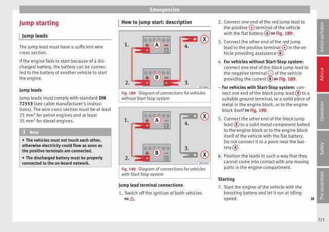
Emergencies
Jump starting
Jump leads
The jump lead must have a sufficient wirecross section.
If the engine fails to start because of a dis-charged battery, the battery can be connec-ted to the battery of another vehicle to startthe engine.
Jump leads
Jump leads must comply with standard DIN72553 (see cable manufacturer's instruc-tions). The wire cross section must be at least25 mm2 for petrol engines and at least35 mm2 for diesel engines.
Note
● The vehicles must not touch each other,otherwise electricity could flow as soon asthe positive terminals are connected.
● The discharged battery must be properlyconnected to the on-board network.
How to jump start: description
Fig. 189 Diagram of connections for vehicleswithout Start Stop system
Fig. 190 Diagram of connections for vehicleswith Start Stop system
Jump lead terminal connections
1. Switch off the ignition of both vehicles››› .
2. Connect one end of the red jump lead tothe positive + terminal of the vehiclewith the flat battery A ››› Fig. 189.
3. Connect the other end of the red jumplead to the positive terminal + in the ve-hicle providing assistance B .
4. For vehicles without Start-Stop system:connect one end of the black jump lead tothe negative terminal – of the vehicleproviding the current B ››› Fig. 189.
– For vehicles with Start-Stop system: con-nect one end of the black jump lead X to asuitable ground terminal, to a solid piece ofmetal in the engine block, or to the engineblock itself ››› Fig. 190.
5. Connect the other end of the black jumplead X to a solid metal component boltedto the engine block or to the engine blockitself of the vehicle with the flat battery.Do not connect it to a point near the bat-tery A .
6. Position the leads in such a way that theycannot come into contact with any movingparts in the engine compartment.
Starting
7. Start the engine of the vehicle with theboosting battery and let it run at idlingspeed. »
223
Tech
nical
spec
ificati
ons
Adv
ice
Ope
rati
onS
afet
yTh
e es
sent
ials

Advice
8. Start the engine of the vehicle with the flatbattery and wait 2 or 3 minutes until theengine is “running”.
Removing the jump leads
9. Before you remove the jump leads, switchoff the dipped beam headlights (if theyare switched on).
10.Turn on the heater blower and heated rearwindow in the vehicle with the flat battery.This helps minimise voltage peaks whichare generated when the leads are discon-nected.
11.When the engine is running, disconnectthe leads in reverse order to the detailsgiven above.
Connect the battery clamps so they havegood metal-to-metal contact with the batteryterminals.
If the engine fails to start, switch off the start-er after about 10 seconds and try again afterabout 1 minute.
WARNING
● Please note the safety warnings referring toworking in the engine compartment››› page 198.
● The battery providing assistance must havethe same voltage as the flat battery (12V) andapproximately the same capacity (see imprint
on battery). Failure to comply could result inan explosion.
● Never use jump leads when one of the bat-teries is frozen. Danger of explosion! Even af-ter the battery has thawed, battery acid couldleak and cause chemical burns. If a batteryfreezes, it should be replaced.
● Keep sparks, flames and lighted cigarettesaway from batteries, danger of explosion.Failure to comply could result in an explo-sion.
● Observe the instructions provided by themanufacturer of the jump leads.
● Do not connect the negative cable from theother vehicle directly to the negative terminalof the flat battery. The gas emitted from thebattery could be ignited by sparks. Danger ofexplosion.
● Do not attach the negative cable from theother vehicle to parts of the fuel system or tothe brake line.
● The non-insulated parts of the batteryclamps must not be allowed to touch. Thejump lead attached to the positive batteryterminal must not touch metal parts of the ve-hicle, this can cause a short circuit.
● Position the leads in such a way that theycannot come into contact with any movingparts in the engine compartment.
● Do not lean on the batteries. This could re-sult in chemical burns.
Note
The vehicles must not touch each other, oth-erwise electricity could flow as soon as thepositive terminals are connected.
Towing and tow-starting thevehicle
General information
Read the additional information carefully››› page 35
Points to observe when tow-starting or tow-ing away
If you use a tow rope:
Notes for the driver of the towing vehicle
– The tow rope must be taut before you driveoff.
– Release the clutch very carefully when start-ing the vehicle (manual gearbox), or accel-erate gently (automatic gearbox).
Driving style
Towing requires some experience, especiallywhen using a tow rope. Both drivers shouldbe familiar with the technique required fortowing. Inexperienced drivers should not at-tempt to tow.
224
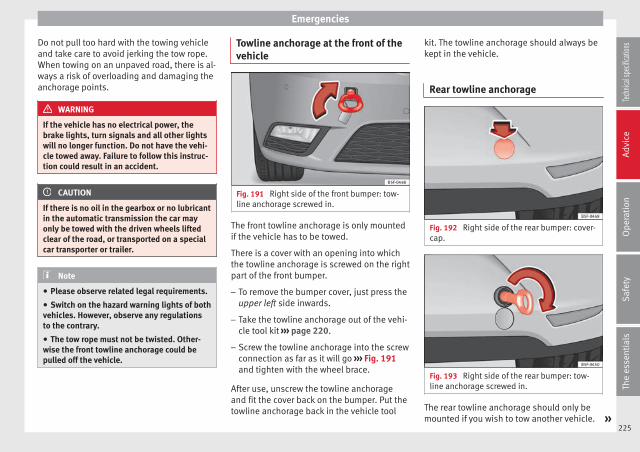
Emergencies
Do not pull too hard with the towing vehicleand take care to avoid jerking the tow rope.When towing on an unpaved road, there is al-ways a risk of overloading and damaging theanchorage points.
WARNING
If the vehicle has no electrical power, thebrake lights, turn signals and all other lightswill no longer function. Do not have the vehi-cle towed away. Failure to follow this instruc-tion could result in an accident.
CAUTION
If there is no oil in the gearbox or no lubricantin the automatic transmission the car mayonly be towed with the driven wheels liftedclear of the road, or transported on a specialcar transporter or trailer.
Note
● Please observe related legal requirements.
● Switch on the hazard warning lights of bothvehicles. However, observe any regulationsto the contrary.
● The tow rope must not be twisted. Other-wise the front towline anchorage could bepulled off the vehicle.
Towline anchorage at the front of thevehicle
Fig. 191 Right side of the front bumper: tow-line anchorage screwed in.
The front towline anchorage is only mountedif the vehicle has to be towed.
There is a cover with an opening into whichthe towline anchorage is screwed on the rightpart of the front bumper.
– To remove the bumper cover, just press theupper left side inwards.
– Take the towline anchorage out of the vehi-cle tool kit ››› page 220.
– Screw the towline anchorage into the screwconnection as far as it will go ››› Fig. 191and tighten with the wheel brace.
After use, unscrew the towline anchorageand fit the cover back on the bumper. Put thetowline anchorage back in the vehicle tool
kit. The towline anchorage should always bekept in the vehicle.
Rear towline anchorage
Fig. 192 Right side of the rear bumper: cover-cap.
Fig. 193 Right side of the rear bumper: tow-line anchorage screwed in.
The rear towline anchorage should only bemounted if you wish to tow another vehicle. »
225
Tech
nical
spec
ificati
ons
Adv
ice
Ope
rati
onS
afet
yTh
e es
sent
ials
Advice
Vehicles with towline anchorage
On the right of the rear bumper there is a cov-er which covers a threaded hole.
– Take the towline anchorage out of the vehi-cle tool set ››› page 220.
– To remove the bumper cover, just press theupper side of the cover inwards (arrow) andremove the cover by levering on the lower››› Fig. 192 side.
– Screw the towline anchorage into the screwconnection as far as it will go ››› Fig. 193and tighten with the wheel brace.
After use, unscrew the towline anchorageand put it back in the vehicle tool kit. Replacethe cover on the bumper. The towline anchor-age should always be kept in the vehicle.
WARNING
● If the towline anchorage is not screwed inas far as the stop, there is a risk of the screwconnection shearing off during towing (acci-dent risk).
● If your car has a towing bracket, only usespecial towing ropes. Risk of accident!
CAUTION
In vehicles fitted with a towing bracket, onlyuse special tow bars to prevent damage tothe ball joint. These tow bars have been spe-cially approved for use with towing brackets.
Tow-starting
As a general rule, tow-starting is not recom-mended.
– Engage 2nd or 3rd gear before moving off.
– Press the clutch and hold the pedal down.
– Switch the ignition on.
– Once both vehicles are moving, release theclutch.
– As soon as the engine has started, pressthe clutch and move the gear lever to neu-tral.
If the engine will not start, it is best to trystarting it using the battery of another vehi-cle ››› page 223 before attempting to towstart. You should only try to tow-start the en-gine if jump starting is not successful. Tow-starting is an attempt to start the engine viathe movement of the wheels.
When tow-starting a vehicle with a petrol en-gine, do not tow it more than a short dis-tance, otherwise unburned fuel can enter thecatalytic converter.
WARNING
The risk of accidents is high when tow-start-ing, for example, the towed vehicle can easilybe driven into the towing vehicle.
CAUTION
Do not tow vehicles for more than 50 km. Riskof damage to the catalytic converter.
Towing vehicles with a manualgearbox
Towing is relatively straightforward.
Please observe the relevant instructions››› page 224.
The vehicle can be towed using a tow bar ortow rope in the normal way, with all fourwheels on the road; it can also be towed witheither the front or rear wheels lifted off theroad. The maximum towing speed is 50 km/h(30 mph).
Towing a vehicle equipped withautomatic gearbox
Certain restrictions must be observed whentowing your vehicle.
Please observe the relevant instructions››› page 224.
The vehicle can be towed with a tow bar ortow rope in the normal way, with all fourwheels on the ground. When doing so,please note the following points:
226
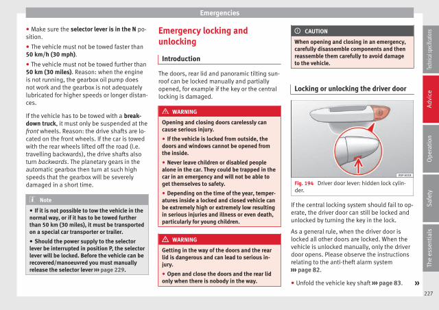
Emergencies
● Make sure the selector lever is in the N po-sition.
● The vehicle must not be towed faster than50 km/h (30 mph).
● The vehicle must not be towed further than50 km (30 miles). Reason: when the engineis not running, the gearbox oil pump doesnot work and the gearbox is not adequatelylubricated for higher speeds or longer distan-ces.
If the vehicle has to be towed with a break-down truck, it must only be suspended at thefront wheels. Reason: the drive shafts are lo-cated on the front wheels. If the car is towedwith the rear wheels lifted off the road (I.e.travelling backwards), the drive shafts alsoturn backwards. The planetary gears in theautomatic gearbox then turn at such highspeeds that the gearbox will be severelydamaged in a short time.
Note
● If it is not possible to tow the vehicle in thenormal way, or if it has to be towed furtherthan 50 km (30 miles), it must be transportedon a special car transporter or trailer.
● Should the power supply to the selectorlever be interrupted in position P, the selectorlever will be locked. Before the vehicle can berecovered/manoeuvred you must manuallyrelease the selector lever ››› page 229.
Emergency locking andunlocking
Introduction
The doors, rear lid and panoramic tilting sun-roof can be locked manually and partiallyopened, for example if the key or the centrallocking is damaged.
WARNING
Opening and closing doors carelessly cancause serious injury.
● If the vehicle is locked from outside, thedoors and windows cannot be opened fromthe inside.
● Never leave children or disabled peoplealone in the car. They could be trapped in thecar in an emergency and will not be able toget themselves to safety.
● Depending on the time of the year, temper-atures inside a locked and closed vehicle canbe extremely high or extremely low resultingin serious injuries and illness or even death,particularly for young children.
WARNING
Getting in the way of the doors and the rearlid is dangerous and can lead to serious in-jury.
● Open and close the doors and the rear lidonly when there is nobody in the way.
CAUTION
When opening and closing in an emergency,carefully disassemble components and thenreassemble them carefully to avoid damageto the vehicle.
Locking or unlocking the driver door
Fig. 194 Driver door lever: hidden lock cylin-der.
If the central locking system should fail to op-erate, the driver door can still be locked andunlocked by turning the key in the lock.
As a general rule, when the driver door islocked all other doors are locked. When thevehicle is unlocked manually, only the driverdoor opens. Please observe the instructionsrelating to the anti-theft alarm system››› page 82.
● Unfold the vehicle key shaft ››› page 83. »227
Tech
nical
spec
ificati
ons
Adv
ice
Ope
rati
onS
afet
yTh
e es
sent
ials

Advice
● Insert the key shaft into the opening in thecover on the driver door handle from below››› Fig. 194 (arrow) then remove the cover up-wards.
● Insert the key shaft into the lock cylinder tounlock or lock the vehicle.
Unlocking notes:
● The anti-theft alarm will remain active whenvehicles are unlocked. However, the alarmwill not yet be triggered ››› page 82.
● After the driver door is opened, you have15 seconds to switch on the ignition. After 15seconds, the alarm is triggered.
● Switch the ignition on. When the ignition isswitched on, the electronic immobiliser rec-ognises a valid vehicle key and deactivatesthe anti-theft alarm system.
Note
The anti-theft alarm is not activated when thevehicle is locked manually using the keyshaft ››› page 82.
Manual locking of the doors with nolock cylinder
Fig. 195 Locking the door manually.
If the central locking system should fail towork at any time, the doors with no lock cyl-inder will have to be locked separately.
A mechanical locking device (only visiblewhen the door is open) is provided on thefront passenger door.
– Pull the cap out of the opening.
– Insert the key in the inside slot and turn itto the right as far as it will go (if the door ison the right side) or to the left (if the dooris on the left side).
Once the door has been closed it can no lon-ger be opened from the outside. Pull the inte-rior door handle once to unlock and open thedoor.
Manual release of the rear lid3 Applies to the model: LEON/LEON SC
Fig. 196 Luggage compartment: access tomanual release.
The rear lid can be unlocked manually frominside in the event of an emergency.
– Insert the key in the opening in the liningof the tail gate 1 and move the key in thedirection of the arrow until the lock is re-leased.
228
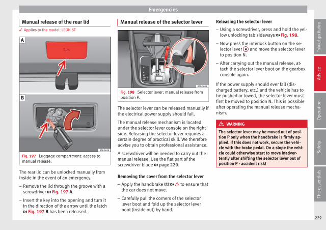
Emergencies
Manual release of the rear lid3 Applies to the model: LEON ST
Fig. 197 Luggage compartment: access tomanual release.
The rear lid can be unlocked manually frominside in the event of an emergency.
– Remove the lid through the groove with ascrewdriver ››› Fig. 197 A.
– Insert the key into the opening and turn itin the direction of the arrow until the latch››› Fig. 197 B has been released.
Manual release of the selector lever
Fig. 198 Selector lever: manual release fromposition P.
The selector lever can be released manually ifthe electrical power supply should fail.
The manual release mechanism is locatedunder the selector lever console on the rightside. Releasing the selector lever requires acertain degree of practical skill. We thereforeadvise you to obtain professional assistance.
A screwdriver will be needed to carry out themanual release. Use the flat part of thescrewdriver blade ››› page 220.
Removing the cover from the selector lever
– Apply the handbrake ››› to ensure thatthe car does not move.
– Carefully pull the corners of the selectorlever boot and fold up the selector leverboot (inside out) by hand.
Releasing the selector lever
– Using a screwdriver, press and hold the yel-low unlocking tab sideways ››› Fig. 198.
– Now press the interlock button on the se-lector lever A and move the selector leverto position N.
– After carrying out the manual release, at-tach the selector lever boot on the gearboxconsole again.
If the power supply should ever fail (dis-charged battery, etc.) and the vehicle has tobe pushed or towed, the selector lever mustfirst be moved to position N. This is possibleafter operating the manual release mecha-nism.
WARNING
The selector lever may be moved out of posi-tion P only when the handbrake is firmly ap-plied. If this does not work, secure the vehi-cle with the brake pedal. On a slope the vehi-cle could otherwise start to move inadver-tently after shifting the selector lever out ofposition P - accident risk!
229
Tech
nical
spec
ificati
ons
Adv
ice
Ope
rati
onS
afet
yTh
e es
sent
ials
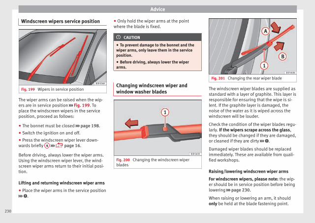
Advice
Windscreen wipers service position
Fig. 199 Wipers in service position
The wiper arms can be raised when the wip-ers are in service position ››› Fig. 199. Toplace the windscreen wipers in the serviceposition, proceed as follows:
● The bonnet must be closed ››› page 198.
● Switch the ignition on and off.
● Press the windscreen wiper lever down-wards briefly 4 ››› page 16.
Before driving, always lower the wiper arms.Using the windscreen wiper lever, the wind-screen wiper arms return to their initial posi-tion.
Lifting and returning windscreen wiper arms
● Place the wiper arms in the service position››› .
● Only hold the wiper arms at the pointwhere the blade is fixed.
CAUTION
● To prevent damage to the bonnet and thewiper arms, only leave them in the serviceposition.
● Before driving, always lower the wiperarms.
Changing windscreen wiper andwindow washer blades
Fig. 200 Changing the windscreen wiperblades
Fig. 201 Changing the rear wiper blade
The windscreen wiper blades are supplied asstandard with a layer of graphite. This layer isresponsible for ensuring that the wipe is si-lent. If the graphite layer is damaged, thenoise of the water as it is wiped across thewindscreen will be louder.
Check the condition of the wiper blades regu-larly. If the wipers scrape across the glass,they should be changed if they are damaged,or cleaned if they are dirty ››› .
Damaged wiper blades should be replacedimmediately. These are available from quali-fied workshops.
Raising/lowering windscreen wiper arms
For windscreen wipers, please note: the wip-er should be in service position before beinglowering ››› page 230.
When raising or lowering an arm, it shouldonly be held at the blade fastening point.
230

Fuses and bulbs
Cleaning windscreen wiper blades
● Raising the wiper arms.
● Use a soft cloth to remove dust and dirtfrom the windscreen wiper blades.
● If the blades are very dirty, a sponge ordamp cloth may be used ››› .
Changing the windscreen wiper blades
● Raising/lowering wiper arms
● Hold down the release button››› Fig. 200 1 while gently pulling the bladein the direction of the arrow.
● Fit a new wiper blade of the same lengthand design on to the wiper arm and hook itinto place.
● Rest the wiper arms back onto the wind-screen.
Changing the rear wiper blade
● Raising/lowering the wiper arm.
● Turn the blade slightly ››› Fig. 201 (arrowA ).
● Hold down the release button 1 whilegently pulling the blade in the direction ofthe arrow B .
● Insert a new blade of the same length andtype in the rear wiper arm in the opposite di-rection to the arrow B and hook into placebutton 1 .
● Replace the wiper arm on the rear window.
WARNING
Worn or dirty wiper blades reduce visibilityand increase the risk of accident and seriousinjury.
● Always replace damaged or worn blades orblades which do not clean the windscreencorrectly.
CAUTION
● Damaged or dirty windscreen wipers couldscratch the glass.
● If products containing solvents, roughsponges or sharp objects are used to cleanthe blades, the graphite layer will be dam-aged.
● Never use fuel, nail varnish remover, paintthinner or similar products to clean the win-dows.
● In icy conditions, always check that thewiper blades are not frozen to the glass be-fore using the wipers. In cold weather, it mayhelp to leave the vehicle parked with the wip-ers in service position ››› page 230.
Fuses and bulbs
Fuses
Introduction
Due to the constant updating of vehicles,fuse assignments based on equipment andthe use of the same fuse for various electricalcomponents, it is not possible to provide anup-to-date summary of the fuse positions forthe electrical components at the time thismanual was printed. For detailed informationabout the fuse positions, please consult atechnical service.
In general, a fuse can be assigned to variouselectrical components. Likewise, an electricalcomponent can be protected by severalfuses.
Only replace fuses when the cause of theproblem has been solved. If a newly insertedfuse blows after a short time, you must havethe electrical system checked by a special-ised workshop as soon as possible.
WARNING
The high voltages in the electrical system cangive serious electrical shocks, causing burnsand even death!
● Never touch the electrical wiring of the igni-tion system. »
231
Tech
nical
spec
ificati
ons
Adv
ice
Ope
rati
onS
afet
yTh
e es
sent
ials
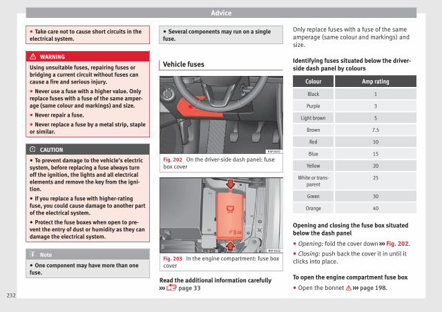
Advice
● Take care not to cause short circuits in theelectrical system.
WARNING
Using unsuitable fuses, repairing fuses orbridging a current circuit without fuses cancause a fire and serious injury.
● Never use a fuse with a higher value. Onlyreplace fuses with a fuse of the same amper-age (same colour and markings) and size.
● Never repair a fuse.
● Never replace a fuse by a metal strip, stapleor similar.
CAUTION
● To prevent damage to the vehicle's electricsystem, before replacing a fuse always turnoff the ignition, the lights and all electricalelements and remove the key from the igni-tion.
● If you replace a fuse with higher-ratingfuse, you could cause damage to another partof the electrical system.
● Protect the fuse boxes when open to pre-vent the entry of dust or humidity as they candamage the electrical system.
Note
● One component may have more than onefuse.
● Several components may run on a singlefuse.
Vehicle fuses
Fig. 202 On the driver-side dash panel: fusebox cover
Fig. 203 In the engine compartment: fuse boxcover
Read the additional information carefully››› page 33
Only replace fuses with a fuse of the sameamperage (same colour and markings) andsize.
Identifying fuses situated below the driver-side dash panel by colours
Colour Amp rating
Black 1
Purple 3
Light brown 5
Brown 7.5
Red 10
Blue 15
Yellow 20
White or trans-parent
25
Green 30
Orange 40
Opening and closing the fuse box situatedbelow the dash panel
● Opening: fold the cover down ››› Fig. 202.
● Closing: push back the cover it in until itclicks into place.
To open the engine compartment fuse box
● Open the bonnet ››› page 198.232
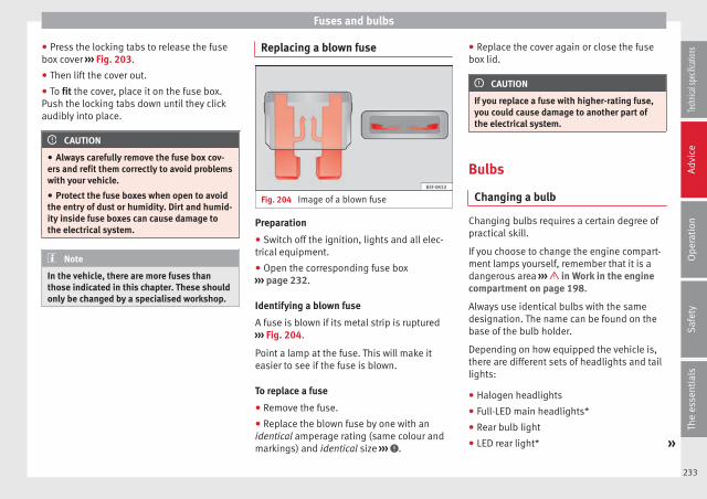
Fuses and bulbs
● Press the locking tabs to release the fusebox cover ››› Fig. 203.
● Then lift the cover out.
● To fit the cover, place it on the fuse box.Push the locking tabs down until they clickaudibly into place.
CAUTION
● Always carefully remove the fuse box cov-ers and refit them correctly to avoid problemswith your vehicle.
● Protect the fuse boxes when open to avoidthe entry of dust or humidity. Dirt and humid-ity inside fuse boxes can cause damage tothe electrical system.
Note
In the vehicle, there are more fuses thanthose indicated in this chapter. These shouldonly be changed by a specialised workshop.
Replacing a blown fuse
Fig. 204 Image of a blown fuse
Preparation
● Switch off the ignition, lights and all elec-trical equipment.
● Open the corresponding fuse box››› page 232.
Identifying a blown fuse
A fuse is blown if its metal strip is ruptured››› Fig. 204.
Point a lamp at the fuse. This will make iteasier to see if the fuse is blown.
To replace a fuse
● Remove the fuse.
● Replace the blown fuse by one with anidentical amperage rating (same colour andmarkings) and identical size ››› .
● Replace the cover again or close the fusebox lid.
CAUTION
If you replace a fuse with higher-rating fuse,you could cause damage to another part ofthe electrical system.
Bulbs
Changing a bulb
Changing bulbs requires a certain degree ofpractical skill.
If you choose to change the engine compart-ment lamps yourself, remember that it is adangerous area ››› in Work in the enginecompartment on page 198.
Always use identical bulbs with the samedesignation. The name can be found on thebase of the bulb holder.
Depending on how equipped the vehicle is,there are different sets of headlights and taillights:
● Halogen headlights
● Full-LED main headlights*
● Rear bulb light
● LED rear light* »
233
Tech
nical
spec
ificati
ons
Adv
ice
Ope
rati
onS
afet
yTh
e es
sent
ials
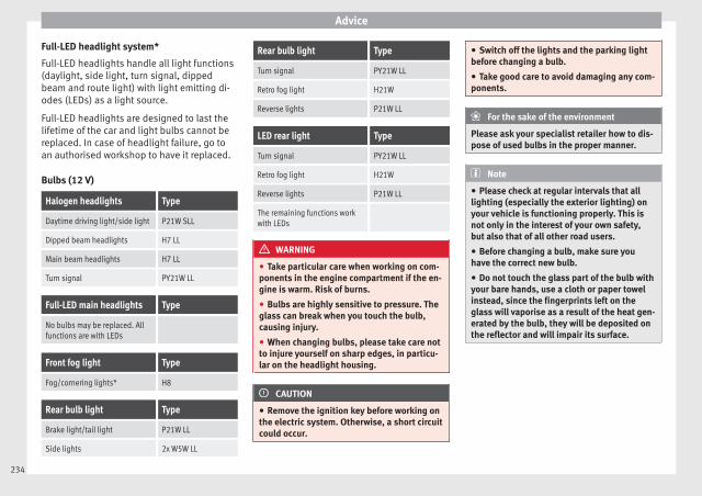
Advice
Full-LED headlight system*
Full-LED headlights handle all light functions(daylight, side light, turn signal, dippedbeam and route light) with light emitting di-odes (LEDs) as a light source.
Full-LED headlights are designed to last thelifetime of the car and light bulbs cannot bereplaced. In case of headlight failure, go toan authorised workshop to have it replaced.
Bulbs (12 V)
Halogen headlights Type
Daytime driving light/side light P21W SLL
Dipped beam headlights H7 LL
Main beam headlights H7 LL
Turn signal PY21W LL
Full-LED main headlights Type
No bulbs may be replaced. Allfunctions are with LEDs
Front fog light Type
Fog/cornering lights* H8
Rear bulb light Type
Brake light/tail light P21W LL
Side lights 2x W5W LL
Rear bulb light Type
Turn signal PY21W LL
Retro fog light H21W
Reverse lights P21W LL
LED rear light Type
Turn signal PY21W LL
Retro fog light H21W
Reverse lights P21W LL
The remaining functions workwith LEDs
WARNING
● Take particular care when working on com-ponents in the engine compartment if the en-gine is warm. Risk of burns.
● Bulbs are highly sensitive to pressure. Theglass can break when you touch the bulb,causing injury.
● When changing bulbs, please take care notto injure yourself on sharp edges, in particu-lar on the headlight housing.
CAUTION
● Remove the ignition key before working onthe electric system. Otherwise, a short circuitcould occur.
● Switch off the lights and the parking lightbefore changing a bulb.
● Take good care to avoid damaging any com-ponents.
For the sake of the environment
Please ask your specialist retailer how to dis-pose of used bulbs in the proper manner.
Note
● Please check at regular intervals that alllighting (especially the exterior lighting) onyour vehicle is functioning properly. This isnot only in the interest of your own safety,but also that of all other road users.
● Before changing a bulb, make sure youhave the correct new bulb.
● Do not touch the glass part of the bulb withyour bare hands, use a cloth or paper towelinstead, since the fingerprints left on theglass will vaporise as a result of the heat gen-erated by the bulb, they will be deposited onthe reflector and will impair its surface.
234

Fuses and bulbs
Changing bulbs in headlightunit
Dipped light bulb
Fig. 205 Dipped beam headlights.
Fig. 206 Dipped beam headlights.
– Raise the bonnet.
– Move the loops ››› Fig. 205 1 in the direc-tion of the arrow and remove the cover.
– Remove connector ››› Fig. 206 2 from thebulb.
– Unclip the retainer spring ››› Fig. 206 3
pressing inwards to the right.
– Extract the bulb and fit the replacement sothat the lug on the base fits into the recesson the reflector.
Day light bulb
Fig. 207 Day light bulb.
– Raise the bonnet.
– Turn the bulb holder ››› Fig. 207 1 to theleft and pull.
– Remove the bulb by pressing on the bulbholder and turning it anti-clockwise at thesame time.
– Installation involves all of the above stepsin reverse sequence.
Turn signal bulb
Fig. 208 Turn signal bulb.
Fig. 209 Turn signal bulb.
– Raise the bonnet.
– Move the loop ››› Fig. 208 1 in the direc-tion of the arrow and remove the cover.
– Turn the bulb holder ››› Fig. 209 2 anti-clockwise and pull. »
235
Tech
nical
spec
ificati
ons
Adv
ice
Ope
rati
onS
afet
yTh
e es
sent
ials

Advice
– Remove the bulb by pressing on the bulbholder and turning it anti-clockwise at thesame time.
– Installation involves all of the above stepsin reverse sequence.
Main beam headlight bulb
Fig. 210 Main beam headlight bulb.
Fig. 211 Main beam headlight bulb.
– Raise the bonnet.
– Move the loop ››› Fig. 210 1 in the direc-tion of the arrow and remove the cover.
– Slide connector ››› Fig. 211 2 to the left orright and pull.
– Remove the bulb by disconnecting the con-nector.
– Installation involves all of the above stepsin reverse sequence.
Changing bulb for front foglight*
Front fog light bulb
Fig. 212 Front fog light.
Fig. 213 Front fog light.
– Remove the bolt ››› Fig. 212 1 from the foglight grille with a screwdriver.
– Remove the bolts (3x) ››› Fig. 213 2 to re-move the fog light.
– Remove the fog light.
Note
Due to the difficulty of accessing fog lightbulbs, have them replaced at a TechnicalService or specialised workshop.
236

Fuses and bulbs
Fog light, FR version
Fig. 214 Fog light: access to the connectorand to the light bulb holder.
Fig. 215 Fog light: access to the connectorand to the light bulb holder.
– Remove the 3 bolts 1 ››› Fig. 214 from theinside of the wheel housing and the 2 bot-tom bolts 2 ››› Fig. 214 from the bumperwith the help of a screwdriver.
– Pull the wheel housing 3 ››› Fig. 215 ac-cess the 2 hidden screws 4 ››› Fig. 215 ofthe bumper.
– Remove the screws using a screwdriver.
– Pull the bumper to release it from its an-chorages to access the connector and thelight bulb holder.
Note
Due to the difficulty of accessing fog lightbulbs, have them replaced at a TechnicalService or specialised workshop.
Remove the bulb holder
Fig. 216 Front fog light.
– Remove connector ››› Fig. 216 1 from thebulb.
– Turn the bulb holder ››› Fig. 216 2 anti-clockwise and pull.
– Remove the bulb by pressing on the bulbholder and turning it anti-clockwise at thesame time.
– Installation involves all of the above stepsin reverse sequence.
– Check that the bulb works properly.
Changing tail light bulbs (onside panel)
Overview of tail lights
Rear lights on the side panel
Turn signal PY21W NA LL
Side light and brake light P21W LL
237
Tech
nical
spec
ificati
ons
Adv
ice
Ope
rati
onS
afet
yTh
e es
sent
ials

Advice
Removing tail light
Fig. 217 Luggage compartment: location ofthe bolt securing the tail light unit.
Fig. 218 Remove the rear light unit from sidepanel.
– Check which of the bulbs is defective.
– Open the rear lid.
– Remove the cover by prying the flat side ofa screwdriver into the recess and removethe cover from the opening ››› Fig. 217 1 .
– Carefully loosen the screw located behindthe cover with a screwdriver, turning it anti-clockwise (arrows) ››› Fig. 217 2 .
– Tilt the light in the direction of the arrowsuntil it comes out (positions 3 and 4
››› Fig. 218).
– Remove the bulb holder ››› page 238.
CAUTION
Take care when removing the rear light unit tomake sure there is no damage to the paint-work or any of its components.
Note
Make sure you have a soft cloth ready toplace under the glass on the rear light unit, toavoid any scratches.
Remove the bulb holder
Fig. 219 Retaining tabs on reverse side of taillight.
– Remove the bulb holder ››› Fig. 219 unlock-ing the retaining tabs 1 .
– Raise the bulb holder.
– Change the defective bulb.
– To refit follow the steps in reverse order,taking special care when fitting the bulbholder. And especially that all retainingtabs are properly secured.
– Place the light back into place and tightenwith a screwdriver.
Note
In the case of LED lights, change only the turnsignal bulb.
238

Fuses and bulbs
Changing tail light bulbs (onrear lid)
Overview of tail lights
Rear lights on tailgate
Left side
Side lights 2x W5W LL
Fog lights H21 W
Right side
Side lights 2x W5W LL
Reverse light P21W LL
The table corresponds to a right-hand trafficvehicle. The position of lights may vary ac-cording to the country.
Remove the bulb holder
Fig. 220 Remove the cover from the boot lid.
Fig. 221 Remove the lamp holder
The rear lid must be open to change thebulbs.
– Remove the rear lid cover in the directionindicated ››› Fig. 220.
– Unlock the retaining tabs A of the bulbholder, following the direction of arrows 1
and 2 ››› Fig. 221.
– Remove the bulb holder by turning it in thedirection of arrow 3 ››› Fig. 221.
Changing bulbs
Fig. 222 Position of the bulbs in the bulbholder
– Lightly press the defective bulb into thebulb holder ››› Fig. 222 1 , then turn it tothe left 2 and remove it.
– Fit the new bulb, pressing it into the bulbholder and turn it to the right as far as itwill go.
– Use a cloth to remove any fingerprints fromthe glass part of the bulb.
– Check that the new bulb works properly.
– Replace the bulb holder. »
239
Tech
nical
spec
ificati
ons
Adv
ice
Ope
rati
onS
afet
yTh
e es
sent
ials
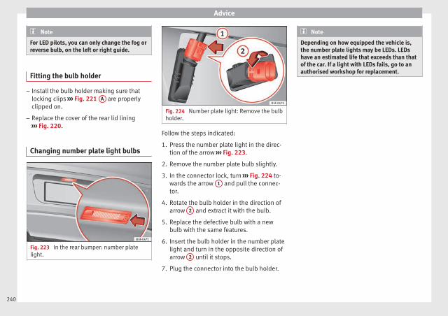
Advice
Note
For LED pilots, you can only change the fog orreverse bulb, on the left or right guide.
Fitting the bulb holder
– Install the bulb holder making sure thatlocking clips ››› Fig. 221 A are properlyclipped on.
– Replace the cover of the rear lid lining››› Fig. 220.
Changing number plate light bulbs
Fig. 223 In the rear bumper: number platelight.
Fig. 224 Number plate light: Remove the bulbholder.
Follow the steps indicated:
1. Press the number plate light in the direc-tion of the arrow ››› Fig. 223.
2. Remove the number plate bulb slightly.
3. In the connector lock, turn ››› Fig. 224 to-wards the arrow 1 and pull the connec-tor.
4. Rotate the bulb holder in the direction ofarrow 2 and extract it with the bulb.
5. Replace the defective bulb with a newbulb with the same features.
6. Insert the bulb holder in the number platelight and turn in the opposite direction ofarrow 2 until it stops.
7. Plug the connector into the bulb holder.
Note
Depending on how equipped the vehicle is,the number plate lights may be LEDs. LEDshave an estimated life that exceeds than thatof the car. If a light with LEDs fails, go to anauthorised workshop for replacement.
240
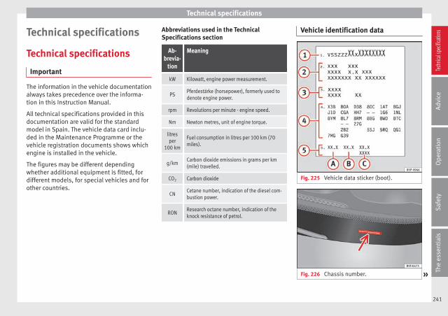
Technical specifications
Technical specifications
Technical specifications
Important
The information in the vehicle documentationalways takes precedence over the informa-tion in this Instruction Manual.
All technical specifications provided in thisdocumentation are valid for the standardmodel in Spain. The vehicle data card inclu-ded in the Maintenance Programme or thevehicle registration documents shows whichengine is installed in the vehicle.
The figures may be different dependingwhether additional equipment is fitted, fordifferent models, for special vehicles and forother countries.
Abbreviations used in the TechnicalSpecifications section
Ab-brevia-
tion
Meaning
kW Kilowatt, engine power measurement.
PSPferdestärke (horsepower), formerly used todenote engine power.
rpm Revolutions per minute - engine speed.
Nm Newton metres, unit of engine torque.
litresper
100 km
Fuel consumption in litres per 100 km (70miles).
g/kmCarbon dioxide emissions in grams per km(mile) travelled.
CO2 Carbon dioxide
CNCetane number, indication of the diesel com-bustion power.
RONResearch octane number, indication of theknock resistance of petrol.
Vehicle identification data
Fig. 225 Vehicle data sticker (boot).
Fig. 226 Chassis number. »
241
Tech
nical
spec
ificati
ons
Adv
ice
Ope
rati
onS
afet
yTh
e es
sent
ials
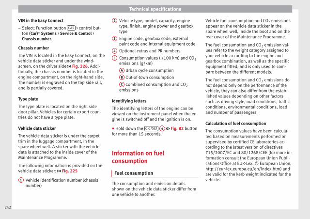
Technical specifications
VIN in the Easy Connect
– Select: Function button CAR > control but-ton (Car)* Systems > Service & Control >Chassis number.
Chassis number
The VIN is located in the Easy Connect, on thevehicle data sticker and under the wind-screen, on the driver side ››› Fig. 226. Addi-tionally, the chassis number is located in theengine compartment, on the right-hand side.The number is engraved on the top side rail,and is partially covered.
Type plate
The type plate is located on the right sidedoor pillar. Vehicles for certain export coun-tries do not have a type plate.
Vehicle data sticker
The vehicle data sticker is under the carpettrim in the luggage compartment, in thespare wheel well. A sticker with the vehicledata is attached to the inside cover of theMaintenance Programme.
The following information is provided on thevehicle data sticker: ››› Fig. 225
Vehicle identification number (chassisnumber)
1
Vehicle type, model, capacity, enginetype, finish, engine power and gearboxtype
Engine code, gearbox code, externalpaint code and internal equipment code
Optional extras and PR numbers
Consumption values (l/100 km) and CO2
emissions (g/km)
A Urban cycle consumption
B Out-of-town consumption
C Combined consumption and CO2
emissions
Identifying letters
The identifying letters of the engine can beviewed on the instrument panel when the en-gine is switched off and the ignition is on.
● Hold down the 0.0/SET 4 ››› Fig. 82 buttonfor more than 15 seconds.
Information on fuelconsumption
Fuel consumption
The consumption and emission detailsshown on the vehicle data sticker differ fromone vehicle to another.
2
3
4
5
Vehicle fuel consumption and CO2 emissionsappear on the vehicle data sticker in thespare wheel well, inside the boot and on therear cover of the Maintenance Programme.
The fuel consumption and CO2 emission val-ues refer to the weight category assigned toyour vehicle according to the engine andgearbox combination, as well as the specificequipment fitted, and is only used to com-pare between the different models.
The fuel consumption and CO2 emissions donot depend only on the performance of thevehicle, they can also differ from the estab-lished values depending on other factorssuch as driving style, road conditions, trafficconditions, environmental conditions, loadand number of passengers.
Calculation of fuel consumption
The consumption values have been calcula-ted based on measurements performed orsupervised by certified CE laboratories ac-cording to the latest version of directives715/2007/EC and 80/1268/CEE (for more in-formation consult the European Union Publi-cations Office at EUR-Lex: © European Union,http://eur-lex.europa.eu/en/index.htm) andare valid for the kerb weight indicated for thevehicle.
242
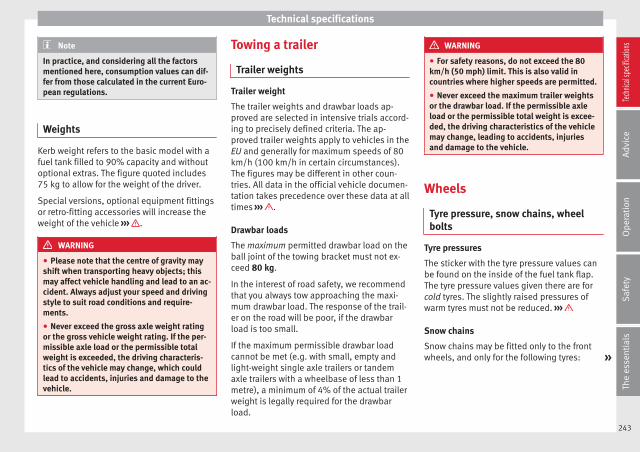
Technical specifications
Note
In practice, and considering all the factorsmentioned here, consumption values can dif-fer from those calculated in the current Euro-pean regulations.
Weights
Kerb weight refers to the basic model with afuel tank filled to 90% capacity and withoutoptional extras. The figure quoted includes75 kg to allow for the weight of the driver.
Special versions, optional equipment fittingsor retro-fitting accessories will increase theweight of the vehicle ››› .
WARNING
● Please note that the centre of gravity mayshift when transporting heavy objects; thismay affect vehicle handling and lead to an ac-cident. Always adjust your speed and drivingstyle to suit road conditions and require-ments.
● Never exceed the gross axle weight ratingor the gross vehicle weight rating. If the per-missible axle load or the permissible totalweight is exceeded, the driving characteris-tics of the vehicle may change, which couldlead to accidents, injuries and damage to thevehicle.
Towing a trailer
Trailer weights
Trailer weight
The trailer weights and drawbar loads ap-proved are selected in intensive trials accord-ing to precisely defined criteria. The ap-proved trailer weights apply to vehicles in theEU and generally for maximum speeds of 80km/h (100 km/h in certain circumstances).The figures may be different in other coun-tries. All data in the official vehicle documen-tation takes precedence over these data at alltimes ››› .
Drawbar loads
The maximum permitted drawbar load on theball joint of the towing bracket must not ex-ceed 80 kg.
In the interest of road safety, we recommendthat you always tow approaching the maxi-mum drawbar load. The response of the trail-er on the road will be poor, if the drawbarload is too small.
If the maximum permissible drawbar loadcannot be met (e.g. with small, empty andlight-weight single axle trailers or tandemaxle trailers with a wheelbase of less than 1metre), a minimum of 4% of the actual trailerweight is legally required for the drawbarload.
WARNING
● For safety reasons, do not exceed the 80km/h (50 mph) limit. This is also valid incountries where higher speeds are permitted.
● Never exceed the maximum trailer weightsor the drawbar load. If the permissible axleload or the permissible total weight is excee-ded, the driving characteristics of the vehiclemay change, leading to accidents, injuriesand damage to the vehicle.
Wheels
Tyre pressure, snow chains, wheelbolts
Tyre pressures
The sticker with the tyre pressure values canbe found on the inside of the fuel tank flap.The tyre pressure values given there are forcold tyres. The slightly raised pressures ofwarm tyres must not be reduced. ›››
Snow chains
Snow chains may be fitted only to the frontwheels, and only for the following tyres: »
243
Tech
nical
spec
ificati
ons
Adv
ice
Ope
rati
onS
afet
yTh
e es
sent
ials
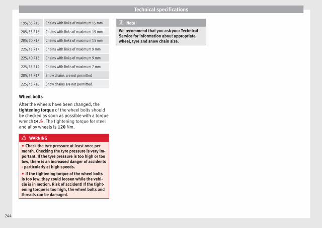
Technical specifications
195/65 R15 Chains with links of maximum 15 mm
205/55 R16 Chains with links of maximum 15 mm
205/50 R17 Chains with links of maximum 15 mm
225/45 R17 Chains with links of maximum 9 mm
225/40 R18 Chains with links of maximum 9 mm
225/35 R19 Chains with links of maximum 7 mm
205/55 R17 Snow chains are not permitted
225/45 R18 Snow chains are not permitted
Wheel bolts
After the wheels have been changed, thetightening torque of the wheel bolts shouldbe checked as soon as possible with a torquewrench ››› . The tightening torque for steeland alloy wheels is 120 Nm.
WARNING
● Check the tyre pressure at least once permonth. Checking the tyre pressure is very im-portant. If the tyre pressure is too high or toolow, there is an increased danger of accidents- particularly at high speeds.
● If the tightening torque of the wheel boltsis too low, they could loosen while the vehi-cle is in motion. Risk of accident! If the tight-ening torque is too high, the wheel bolts andthreads can be damaged.
Note
We recommend that you ask your TechnicalService for information about appropriatewheel, tyre and snow chain size.
244
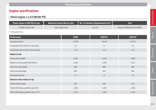
Technical specifications
Engine specifications
Petrol engine 1.2 63 kW (85 PS)
Power output in kW (PS) at rpm Maximum torque (Nm at rpm) No. of cylinders/displacement (cm3) Fuel
63 (86)/4,300-5,300 160/1,400-3,500 4/1,197 Super 95 RON/Normal 91 RONa)
a) Slight power loss.
Performance LEON LEON SC LEON ST
Top speed (km/h) 178 (V) 178 (V) 178 (V)
Acceleration from 0-80 km/h (seconds) 7.6 7.5 7.8
Acceleration from 0-100 km/h (seconds) 11.9 11.8 12.1
Weights (in kg)
Gross vehicle weight 1,690 1,700 1,800
Weight in running order (with driver) 1,188 1,168 1,233
Gross front axle weight 880 880 890
Gross rear axle weight 860 870 960
Permitted roof load 75 75 75
Maximum trailer weights (in kg)
Trailer without brakes 590 580 610
Trailer with brakes, gradients up to 8% 1,300 1,300 1,300
Trailer with brakes, gradients up to 12% 1,100 1,100 1,100
245
Tech
nical
spec
ificati
ons
Adv
ice
Ope
rati
onS
afet
yTh
e es
sent
ials

Technical specifications
Petrol engine 1.2 77 kW (105 PS)
Power output in kW (PS) at rpm Maximum torque (Nm at rpm) No. of cylinders/displacement (cm3) Fuel
77 (105)/4,500-5,500 175/1,400-4,000 4/1,197 Super 95 RON/Normal 91 RONa)
a) Slight power loss.
PerformanceLEON
ManualLEON
Start-StopLEON
AutomaticLEON SCManual
LEON SCStart-Stop
LEON SCAutomatic
LEON STManual
LEON STStart-Stop
LEON STAutomatic
Top speed (km/h) 191 (V) 191 (V) 191 (VI) 191 (V) 191 (V) 191 (V) 191 (V) 191 (V) 191 (VI)
Acceleration from 0-80 km/h (sec-onds)
6.8 6.8 6.8 6.7 6.7 6.7 6.9 6.8 7.0
Acceleration from 0-100 km/h (sec-onds)
10.2 10.2 10.2 10 10 10 10.4 10.3 10.3
Weights (in kg)
Gross vehicle weight 1,720 1,720 1,750 1,710 1,710 1,730 1,810 1,820 1,850
Weight in running order (with driv-er)
1,199 1,209 1,235 1,179 1,189 1,215 1,244 1,254 1,280
Gross front axle weight 890 890 920 880 890 920 880 890 920
Gross rear axle weight 880 880 880 880 870 860 980 980 980
Permitted roof load 75 75 75 75 75 75 75 75 75
Maximum trailer weights (in kg)
Trailer without brakes 590 600 610 580 590 600 620 620 640
Trailer with brakes, gradients up to8%
1,500 1,500 1,500 1,500 1,500 1,500 1,500 1,500 1,500
Trailer with brakes, gradients up to12%
1,300 1,300 1,300 1,300 1,300 1,300 1,300 1,300 1,300
246

Technical specifications
Petrol engine 1.2 TSI 81 kW (110 PS)
Power output in kW (PS) at rpm Maximum torque (Nm at rpm) No. of cylinders/displacement (cm3) Fuel
81 (110)/4,600-5,600 175/1,400-4,000 4/1,197 Super 95 RON/Normal 91 RONa)
a) Slight power loss.
PerformanceLEON LEON SC LEON ST
Manual Start-Stop Automatic Manual Start-Stop Automatic Manual Start-Stop Automatic
Top speed (km/h) 194 (V) 194 (V) 194 (V) 194 (V) 194 (V) 194 (VI) 194 (V) 194 (V) 194 (VI)
Acceleration from 0-80 km/h (seconds) 6.6 6.6 6.6 6.5 6.5 6.5 6.7 6.7 6.7
Acceleration from 0-100 km/h (seconds) 9.9 9.9 9.9 9.7 9.7 9.7 10.1 10.1 10.1
Weights (in kg)
Gross vehicle weight 1,740 1,740 1,760 1,710 1,720 1,750 1,790 1,800 1,820
Weight in running order (with driver) 1,206 1,213 1,241 1,186 1,193 1,221 1,240 1,247 1,275
Gross front axle weight 900 900 930 890 890 920 890 890 920
Gross rear axle weight 890 890 880 870 880 880 950 960 950
Permitted roof load 75 75 75 75 75 75 75 75 75
Maximum trailer weights (in kg)
Trailer without brakes 600 600 620 590 590 610 620 620 630
Trailer with brakes, gradients up to 8% 1,500 1,500 1,500 1,500 1,500 1,500 1,500 1,500 1,500
Trailer with brakes, gradients up to 12% 1,300 1,300 1,300 1,300 1,300 1,300 1,300 1,300 1,300
247
Tech
nical
spec
ificati
ons
Adv
ice
Ope
rati
onS
afet
yTh
e es
sent
ials

Technical specifications
Petrol engine 1.4 90 kW (122 PS) Start-Stop
Power output in kW (PS) at rpm Maximum torque (Nm at rpm) No. of cylinders/displacement (cm3) Fuel
90 (122)/5,000-6,000 200/1,400-4,000 4/1,395 Super 95 RON/Normal 91 RONa)
a) Slight power loss.
PerformanceLEON
Start-StopLEON SC
Start-StopLEON ST
Start-Stop
Top speed (km/h) 202 (V&VI) 202 (V&VI) 202 (V&VI)
Acceleration from 0-80 km/h (seconds) 6.3 6.2 6.5
Acceleration from 0-100 km/h (seconds) 9.3 9.1 9.6
Weights (in kg)
Gross vehicle weight 1,740 1,710 1,840
Weight in running order (with driver) 1,224 1,204 1,269
Gross front axle weight 910 910 910
Gross rear axle weight 880 850 980
Permitted roof load 75 75 75
Maximum trailer weights (in kg)
Trailer without brakes 610 600 630
Trailer with brakes, gradients up to 8% 1,700 1,700 1,700
Trailer with brakes, gradients up to 12% 1,400 1,400 1,400
248

Technical specifications
Petrol engine 1.4 92 kW (125 PS) Start-Stop
Power output in kW (PS) at rpm Maximum torque (Nm at rpm) No. of cylinders/displacement (cm3) Fuel
92 (125)/5,000-6,000 200/1,400-4,000 4/1,395 Super 95 RON/Normal 91 RONa)
a) Slight power loss.
Performance LEON LEON SC LEON ST
Top speed (km/h) 203 (V&VI) 203 (V&VI) 203 (V&VI)
Acceleration from 0-80 km/h (seconds) 6.2 6.1 6.4
Acceleration from 0-100 km/h (seconds) 9.1 8.9 9.4
Weights (in kg)
Gross vehicle weight 1,770 1,750 1,840
Weight in running order (with driver) 1,233 1,213 1,267
Gross front axle weight 920 910 910
Gross rear axle weight 900 890 970
Permitted roof load 75 75 75
Maximum trailer weights (in kg)
Trailer without brakes 610 600 630
Trailer with brakes, gradients up to 8% 1,700 1,700 1,700
Trailer with brakes, gradients up to 12% 1,400 1,400 1,400
249
Tech
nical
spec
ificati
ons
Adv
ice
Ope
rati
onS
afet
yTh
e es
sent
ials

Technical specifications
Petrol engine 1.4 103 kW (140 PS) Start-Stop
Power output in kW (PS) at rpm Maximum torque (Nm at rpm) No. of cylinders/displacement (cm3) Fuel
103 (140)/4,500-6,000 250/1,500-3,500 4/1,395 Super 95 RON/Normal 91 RONa)
a) Slight power loss.
PerformanceLEON
Start-StopLEON
AutomaticLEON SC
Start-StopLEON SC
AutomaticLEON ST
Start-StopLEON ST
Automatic
Top speed (km/h) 211 (VI) 211 (VI) 211 (VI) 211 (VI) 211 (VI) 211 (VI)
Acceleration from 0-80 km/h (seconds) 5.7 5.7 5.6 5.6 5.9 5.9
Acceleration from 0-100 km/h (seconds) 8.2 8.2 8.1 8.1 8.4 8.4
Weights (in kg)
Gross vehicle weight 1,730 1,730 1,740 1,740 1,840 1,860
Weight in running order (with driver) 1,231 1,246 1,211 1,226 1,275 1,291
Gross front axle weight 920 930 910 930 910 930
Gross rear axle weight 860 850 880 860 980 980
Permitted roof load 75 75 75 75 75 75
Maximum trailer weights (in kg)
Trailer without brakes 610 620 600 610 630 640
Trailer with brakes, gradients up to 8% 1,700 1,700 1,800 1,700 1,800 1,700
Trailer with brakes, gradients up to 12% 1,500 1,500 1,500 1,500 1,500 1,500
250

Technical specifications
Petrol engine 1.4 TSI 110 kW (150 hp) ACT®
Power output in kW (PS) at rpm Maximum torque (Nm at rpm) No. of cylinders/displacement (cm3) Fuel
110 (150)/5,000-6,000 250/1,500-3,500 4/1,395 Super 95 RON/Normal 91 RONa)
a) Slight power loss.
PerformanceLEON LEON SC LEON ST
manual automatic manual automatic manual automatic
Top speed (km/h) 215 (V&VI) 215 (V&VI) 215 (V&VI) 215 (V&VI) 215 (V&VI) 215 (V&VI)
Acceleration from 0-80 km/h (seconds) 5.6 5.6 5.5 5.5 5.5 5.5
Acceleration from 0-100 km/h (seconds) 8 8 7.9 7.9 7.9 7.9
Weights (in kg)
Gross vehicle weight 1,760 1,780 1,740 1,760 1,830 1,840
Weight in running order (with driver) 1,241 1,263 1,223 1,243 1,277 1,297
Gross front axle weight 920 940 920 940 920 940
Gross rear axle weight 890 890 870 870 960 950
Permitted roof load 75 75 75 75 75 75
Maximum trailer weights (in kg)
Trailer without brakes 620 630 610 620 630 640
Trailer with brakes, gradients up to 8% 1,700 1,700 1,700 1,700 1,800 1,700
Trailer with brakes, gradients up to 12% 1,500 1,500 1,500 1,500 1,500 1,500
251
Tech
nical
spec
ificati
ons
Adv
ice
Ope
rati
onS
afet
yTh
e es
sent
ials
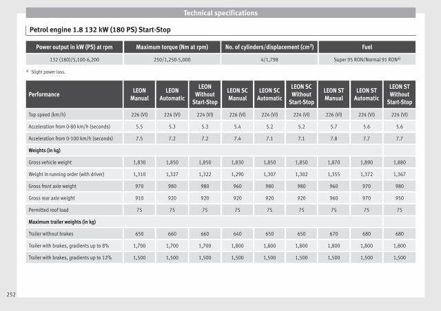
Technical specifications
Petrol engine 1.8 132 kW (180 PS) Start-Stop
Power output in kW (PS) at rpm Maximum torque (Nm at rpm) No. of cylinders/displacement (cm3) Fuel
132 (180)/5,100-6,200 250/1,250-5,000 4/1,798 Super 95 RON/Normal 91 RONa)
a) Slight power loss.
PerformanceLEON
ManualLEON
Automatic
LEONWithout
Start-Stop
LEON SCManual
LEON SCAutomatic
LEON SCWithout
Start-Stop
LEON STManual
LEON STAutomatic
LEON STWithout
Start-Stop
Top speed (km/h) 226 (VI) 224 (VI) 224 (VI) 226 (VI) 224 (VI) 224 (VI) 226 (VI) 224 (VI) 224 (VI)
Acceleration from 0-80 km/h (seconds) 5.5 5.3 5.3 5.4 5.2 5.2 5.7 5.6 5.6
Acceleration from 0-100 km/h (seconds) 7.5 7.2 7.2 7.4 7.1 7.1 7.8 7.7 7.7
Weights (in kg)
Gross vehicle weight 1,830 1,850 1,850 1,830 1,850 1,850 1,870 1,890 1,880
Weight in running order (with driver) 1,310 1,327 1,322 1,290 1,307 1,302 1,355 1,372 1,367
Gross front axle weight 970 980 980 960 980 980 960 970 980
Gross rear axle weight 910 920 920 920 920 920 960 970 950
Permitted roof load 75 75 75 75 75 75 75 75 75
Maximum trailer weights (in kg)
Trailer without brakes 650 660 660 640 650 650 670 680 680
Trailer with brakes, gradients up to 8% 1,700 1,700 1,700 1,800 1,800 1,800 1,800 1,800 1,800
Trailer with brakes, gradients up to 12% 1,500 1,500 1,500 1,500 1,500 1,500 1,500 1,500 1,500
252

Technical specifications
Petrol engine 1.8 TSI 132 kW (180 hp) All-wheel drive
Power output in kW (PS) at rpm Maximum torque (Nm at rpm) No. of cylinders/displacement (cm3) Fuel
132 (180)/4,500-6,200 280/1,350-4,500 4/1,798 Super 95 RON/Normal 91 RONa)
a) Slight power loss.
PerformanceLEON ST
X-PERIENCE 4WD
Top speed (km/h) 221 (V&VI)
Acceleration from 0-80 km/h (seconds) 4.9
Acceleration from 0-100 km/h (seconds) 7.2
Weights (in kg)
Gross vehicle weight 2,010
Weight in running order (with driver) 1,486
Gross front axle weight 1010
Gross rear axle weight 1050
Permitted roof load 75
Maximum trailer weights (in kg)
Trailer without brakes 750
Trailer with brakes, gradients up to 8% 2,000
Trailer with brakes, gradients up to 12% 2,000
253
Tech
nical
spec
ificati
ons
Adv
ice
Ope
rati
onS
afet
yTh
e es
sent
ials
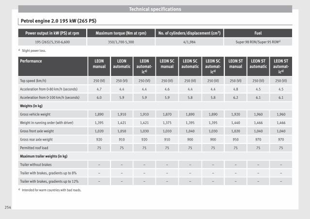
Technical specifications
Petrol engine 2.0 195 kW (265 PS)
Power output in kW (PS) at rpm Maximum torque (Nm at rpm) No. of cylinders/displacement (cm3) Fuel
195 (265)/5,350-6,600 350/1,700-5,300 4/1,984 Super 98 RON/Super 95 RONa)
a) Slight power loss.
Performance LEONmanual
LEONautomatic
LEONautomat-
ica)
LEON SCmanual
LEON SCautomatic
LEON SCautomat-
ica)
LEON STmanual
LEON STautomatic
LEON STautomat-
ica)
Top speed (km/h) 250 (VI) 250 (VI) 250 (VI) 250 (VI) 250 (VI) 250 (VI) 250 (VI) 250 (VI) 250 (VI)
Acceleration from 0-80 km/h (seconds) 4.7 4.4 4.4 4.6 4.4 4.4 4.8 4.5 4.5
Acceleration from 0-100 km/h (seconds) 6.0 5.9 5.9 5.9 5.8 5.8 6.2 6.1 6.1
Weights (in kg)
Gross vehicle weight 1,890 1,910 1,910 1,870 1,890 1,890 1,920 1,960 1,960
Weight in running order (with driver) 1,395 1,421 1,421 1,375 1,395 1,395 1,440 1,466 1,466
Gross front axle weight 1,020 1,050 1,030 1,010 1,040 1,030 1,020 1,040 1,040
Gross rear axle weight 920 910 920 910 900 900 950 970 970
Permitted roof load 75 75 75 75 75 75 75 75 75
Maximum trailer weights (in kg)
Trailer without brakes – – – – – – – – –
Trailer with brakes, gradients up to 8% – – – – – – – – –
Trailer with brakes, gradients up to 12% – – – – – – – – –
a) Intended for warm countries with bad roads.
254

Technical specifications
Petrol engine 2.0 206 kW (280 PS)
Power output in kW (PS) at rpm Maximum torque (Nm at rpm) No. of cylinders/displacement (cm3) Fuel
206 (280)/5,600-6,500 350/1,700-5,600 4/1,984 Super 98 RON/Super 95 RONa)
a) Slight power loss.
Performance LEONmanual
LEONautomatic
LEON SCmanual
LEON SCautomatic
LEON STmanual
LEON STautomatic
Top speed (km/h) 250 (VI) 250 (VI) 250 (VI) 250 (VI) 250 (VI) 250 (VI)
Acceleration from 0-80 km/h (seconds) 4.7 4.5 4.6 4.3 4.8 4.5
Acceleration from 0-100 km/h (seconds) 5.9 5.8 5.8 5.7 6.1 6.0
Weights (in kg)
Gross vehicle weight 1,890 1,910 1,870 1,890 1,920 1,950
Weight in running order (with driver) 1,395 1,421 1,375 1,395 1,440 1,466
Gross front axle weight 1,020 1,050 1,010 1,040 1,020 1,040
Gross rear axle weight 920 910 910 900 950 960
Permitted roof load 75 75 75 75 75 75
Maximum trailer weights (in kg)
Trailer without brakes – – – – – –
Trailer with brakes, gradients up to 8% – – – – – –
Trailer with brakes, gradients up to 12% – – – – – –
255
Tech
nical
spec
ificati
ons
Adv
ice
Ope
rati
onS
afet
yTh
e es
sent
ials

Technical specifications
Petrol/CNG engine 1.4 TSI 81 kW (110 hp)
Power output in kW (PS) at rpm Maximum torque (Nm at rpm) No. of cylinders/displacement (cm3) Fuel
81 (110)/4,800-6,000 200/1,500-3,500 4/1,395 CNGSuper 95 RON/Nor-
mal 91 RONa)
a) Slight power loss.
Performance LEON LEON ST
Top speed (km/h) 194 (V) 194 (VI)
Acceleration from 0-80 km/h (seconds) 7.1 7.3
Acceleration from 0-100 km/h (seconds) 10.9 11
Weights (in kg)
Gross vehicle weight 1,840 1,880
Weight in running order (with driver) 1,359 1,395
Gross front axle weight 910 910
Gross rear axle weight 980 1,020
Permitted roof load 75 75
Maximum trailer weights (in kg)
Trailer without brakes 670 690
Trailer with brakes, gradients up to 8% 1,700 1,700
Trailer with brakes, gradients up to 12% 1,400 1,400
256
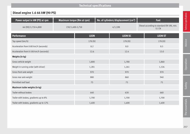
Technical specifications
Diesel engine 1.6 66 kW (90 PS)
Power output in kW (PS) at rpm Maximum torque (Nm at rpm) No. of cylinders/displacement (cm3) Fuel
66 (90)/2,750-4,800 230/1,400-2,750 4/1,598Diesel according to standard EN 590, min.
51 CN
Performance LEON LEON SC LEON ST
Top speed (km/h) 178 (IV) 178 (IV) 178 (IV)
Acceleration from 0-80 km/h (seconds) 8.2 8.0 8.5
Acceleration from 0-100 km/h (seconds) 12.6 12.4 13.0
Weights (in kg)
Gross vehicle weight 1,800 1,780 1,860
Weight in running order (with driver) 1,281 1,261 1,326
Gross front axle weight 970 970 970
Gross rear axle weight 880 860 940
Permitted roof load 75 75 75
Maximum trailer weights (in kg)
Trailer without brakes 640 630 660
Trailer with brakes, gradients up to 8% 1,700 1,700 1,700
Trailer with brakes, gradients up to 12% 1,400 1,400 1,400
257
Tech
nical
spec
ificati
ons
Adv
ice
Ope
rati
onS
afet
yTh
e es
sent
ials
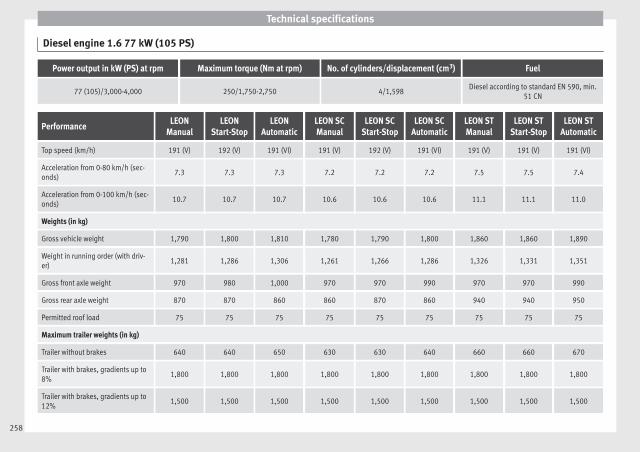
Technical specifications
Diesel engine 1.6 77 kW (105 PS)
Power output in kW (PS) at rpm Maximum torque (Nm at rpm) No. of cylinders/displacement (cm3) Fuel
77 (105)/3,000-4,000 250/1,750-2,750 4/1,598Diesel according to standard EN 590, min.
51 CN
PerformanceLEON
ManualLEON
Start-StopLEON
AutomaticLEON SCManual
LEON SCStart-Stop
LEON SCAutomatic
LEON STManual
LEON STStart-Stop
LEON STAutomatic
Top speed (km/h) 191 (V) 192 (V) 191 (VI) 191 (V) 192 (V) 191 (VI) 191 (V) 191 (V) 191 (VI)
Acceleration from 0-80 km/h (sec-onds)
7.3 7.3 7.3 7.2 7.2 7.2 7.5 7.5 7.4
Acceleration from 0-100 km/h (sec-onds)
10.7 10.7 10.7 10.6 10.6 10.6 11.1 11.1 11.0
Weights (in kg)
Gross vehicle weight 1,790 1,800 1,810 1,780 1,790 1,800 1,860 1,860 1,890
Weight in running order (with driv-er)
1,281 1,286 1,306 1,261 1,266 1,286 1,326 1,331 1,351
Gross front axle weight 970 980 1,000 970 970 990 970 970 990
Gross rear axle weight 870 870 860 860 870 860 940 940 950
Permitted roof load 75 75 75 75 75 75 75 75 75
Maximum trailer weights (in kg)
Trailer without brakes 640 640 650 630 630 640 660 660 670
Trailer with brakes, gradients up to8%
1,800 1,800 1,800 1,800 1,800 1,800 1,800 1,800 1,800
Trailer with brakes, gradients up to12%
1,500 1,500 1,500 1,500 1,500 1,500 1,500 1,500 1,500
258

Technical specifications
Diesel engine 1.6 77 kW (105 HP) All-Wheel Drive
Power output in kW (PS) at rpm Maximum torque (Nm at rpm) No. of cylinders/displacement (cm3) Fuel
77 (105)/3,000-4,000 250/1,750-2,750 4/1,598Diesel according to standard EN 590, min.
51 CN
PerformanceLEON ST
manual gearbox
Top speed (km/h) 187 (VI)
Acceleration from 0-80 km/h (seconds) 7.5
Acceleration from 0-100 km/h (seconds) 12
Weights (in kg)
Gross vehicle weight 1,980
Weight in running order (with driver) 1,455
Gross front axle weight 1,010
Gross rear axle weight 1,020
Permitted roof load 75
Maximum trailer weights (in kg)
Trailer without brakes 720
Trailer with brakes, gradients up to 8% 1,900
Trailer with brakes, gradients up to 12% 1,700
259
Tech
nical
spec
ificati
ons
Adv
ice
Ope
rati
onS
afet
yTh
e es
sent
ials
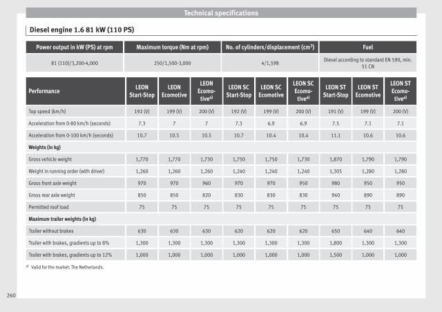
Technical specifications
Diesel engine 1.6 81 kW (110 PS)
Power output in kW (PS) at rpm Maximum torque (Nm at rpm) No. of cylinders/displacement (cm3) Fuel
81 (110)/3,200-4,000 250/1,500-3,000 4/1,598Diesel according to standard EN 590, min.
51 CN
PerformanceLEON
Start-StopLEON
Ecomotive
LEONEcomo-
tivea)
LEON SCStart-Stop
LEON SCEcomotive
LEON SCEcomo-
tivea)
LEON STStart-Stop
LEON STEcomotive
LEON STEcomo-
tivea)
Top speed (km/h) 192 (V) 199 (V) 200 (V) 192 (V) 199 (V) 200 (V) 191 (V) 199 (V) 200 (V)
Acceleration from 0-80 km/h (seconds) 7.3 7 7 7.3 6.9 6.9 7.5 7.1 7.1
Acceleration from 0-100 km/h (seconds) 10.7 10.5 10.5 10.7 10.4 10.4 11.1 10.6 10.6
Weights (in kg)
Gross vehicle weight 1,770 1,770 1,730 1,750 1,750 1,730 1,870 1,790 1,790
Weight in running order (with driver) 1,260 1,260 1,260 1,240 1,240 1,240 1,305 1,280 1,280
Gross front axle weight 970 970 960 970 970 950 980 950 950
Gross rear axle weight 850 850 820 830 830 830 940 890 890
Permitted roof load 75 75 75 75 75 75 75 75 75
Maximum trailer weights (in kg)
Trailer without brakes 630 630 630 620 620 620 650 640 640
Trailer with brakes, gradients up to 8% 1,300 1,300 1,300 1,300 1,300 1,300 1,800 1,300 1,300
Trailer with brakes, gradients up to 12% 1,000 1,000 1,000 1,000 1,000 1,000 1,500 1,000 1,000
a) Valid for the market: The Netherlands.
260
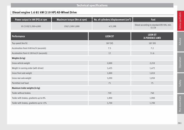
Technical specifications
Diesel engine 1.6 81 kW (110 HP) All-Wheel Drive
Power output in kW (PS) at rpm Maximum torque (Nm at rpm) No. of cylinders/displacement (cm3) Fuel
81 (110)/3,200-4,000 250/1,500-3,000 4/1,598Diesel according to standard EN 590, min.
51 CN
Performance LEON STLEON ST
X-PERIENCE 4WD
Top speed (km/h) 187 (VI) 187 (VI)
Acceleration from 0-80 km/h (seconds) 7.5 7.2
Acceleration from 0-100 km/h (seconds) 12 11.6
Weights (in kg)
Gross vehicle weight 2,000 2,210
Weight in running order (with driver) 1,455 1,472
Gross front axle weight 1,000 1,010
Gross rear axle weight 1,050 1,050
Permitted roof load 75 75
Maximum trailer weights (in kg)
Trailer without brakes 720 740
Trailer with brakes, gradients up to 8% 1,900 1,900
Trailer with brakes, gradients up to 12% 1,700 1,700
261
Tech
nical
spec
ificati
ons
Adv
ice
Ope
rati
onS
afet
yTh
e es
sent
ials
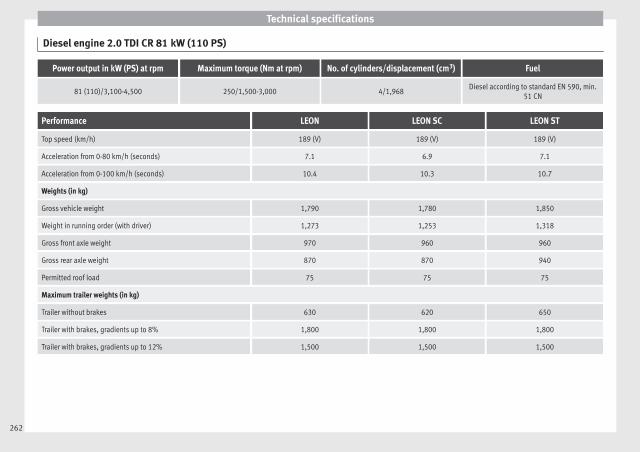
Technical specifications
Diesel engine 2.0 TDI CR 81 kW (110 PS)
Power output in kW (PS) at rpm Maximum torque (Nm at rpm) No. of cylinders/displacement (cm3) Fuel
81 (110)/3,100-4,500 250/1,500-3,000 4/1,968Diesel according to standard EN 590, min.
51 CN
Performance LEON LEON SC LEON ST
Top speed (km/h) 189 (V) 189 (V) 189 (V)
Acceleration from 0-80 km/h (seconds) 7.1 6.9 7.1
Acceleration from 0-100 km/h (seconds) 10.4 10.3 10.7
Weights (in kg)
Gross vehicle weight 1,790 1,780 1,850
Weight in running order (with driver) 1,273 1,253 1,318
Gross front axle weight 970 960 960
Gross rear axle weight 870 870 940
Permitted roof load 75 75 75
Maximum trailer weights (in kg)
Trailer without brakes 630 620 650
Trailer with brakes, gradients up to 8% 1,800 1,800 1,800
Trailer with brakes, gradients up to 12% 1,500 1,500 1,500
262
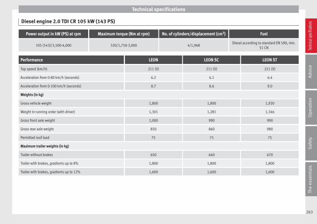
Technical specifications
Diesel engine 2.0 TDI CR 105 kW (143 PS)
Power output in kW (PS) at rpm Maximum torque (Nm at rpm) No. of cylinders/displacement (cm3) Fuel
105 (143)/3,500-4,000 320/1,750-3,000 4/1,968Diesel according to standard EN 590, min.
51 CN
Performance LEON LEON SC LEON ST
Top speed (km/h) 211 (V) 211 (V) 211 (V)
Acceleration from 0-80 km/h (seconds) 6.2 6.1 6.4
Acceleration from 0-100 km/h (seconds) 8.7 8.6 9.0
Weights (in kg)
Gross vehicle weight 1,800 1,800 1,920
Weight in running order (with driver) 1,301 1,281 1,346
Gross front axle weight 1,000 990 990
Gross rear axle weight 850 860 980
Permitted roof load 75 75 75
Maximum trailer weights (in kg)
Trailer without brakes 650 640 670
Trailer with brakes, gradients up to 8% 1,800 1,800 1,800
Trailer with brakes, gradients up to 12% 1,600 1,600 1,600
263
Tech
nical
spec
ificati
ons
Adv
ice
Ope
rati
onS
afet
yTh
e es
sent
ials
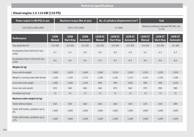
Technical specifications
Diesel engine 2.0 110 kW (150 PS)
Power output in kW (PS) at rpm Maximum torque (Nm at rpm) No. of cylinders/displacement (cm3) Fuel
110 (150)/3,500-4,000 320/1,750-3,000 4/1,968Diesel according to standard EN 590, min.
51 CN
PerformanceLEON
ManualLEON
Start-StopLEON
AutomaticLEON SCManual
LEON SCStart-Stop
LEON SCAutomatic
LEON STManual
LEON STStart-Stop
LEON STAutomatic
Top speed (km/h) 215 (VI) 215 (VI) 211 (VI) 215 (VI) 215 (VI) 211 (VI) 215 (VI) 215 (VI) 211 (VI)
Acceleration from 0-80 km/h (sec-onds)
6.1 6.1 6.0 6.0 6.0 6.0 6.2 6.2 6.2
Acceleration from 0-100 km/h (sec-onds)
8.4 8.4 8.4 8.3 8.3 8.3 8.6 8.6 8.6
Weights (in kg)
Gross vehicle weight 1,800 1,810 1,840 1,800 1,810 1,830 1,910 1,920 1,950
Weight in running order (with driver) 1,300 1,305 1,335 1,280 1,285 1,315 1,345 1,350 1,380
Gross front axle weight 1,000 1,000 1,030 990 990 1020 990 990 1,020
Gross rear axle weight 850 860 860 860 870 860 970 980 980
Permitted roof load 75 75 75 75 75 75 75 75 75
Maximum trailer weights (in kg)
Trailer without brakes 650 650 660 640 640 650 670 650 690
Trailer with brakes, gradients up to8%
1,800 1,800 1,800 1,800 1,800 1,800 1,800 1,800 1,800
Trailer with brakes, gradients up to12%
1,600 1,600 1,600 1,600 1,600 1,600 1,600 1,600 1,600
264

Technical specifications
Diesel engine 2.0 110 kW (150 HP) All-Wheel Drive
Power output in kW (PS) at rpm Maximum torque (Nm at rpm) No. of cylinders/displacement (cm3) Fuel
110 (150)/3,500-4,000 320/1,750-3,000 4/1,968Diesel according to standard EN 590, min.
51 CN
Performance LEON STLEON ST
X-PERIENCE 4WD
Top speed (km/h) 211 (VI) 208 (VI)
Acceleration from 0-80 km/h (seconds) 6.3 6.3
Acceleration from 0-100 km/h (seconds) 8.7 8.7
Weights (in kg)
Gross vehicle weight 1,960 2,020
Weight in running order (with driver) 1,474 1,484
Gross front axle weight 1,020 1,020
Gross rear axle weight 1,050 1,050
Permitted roof load 75 75
Maximum trailer weights (in kg)
Trailer without brakes 730 740
Trailer with brakes, gradients up to 8% 1,900 2,000
Trailer with brakes, gradients up to 12% 1,700 2,000
265
Tech
nical
spec
ificati
ons
Adv
ice
Ope
rati
onS
afet
yTh
e es
sent
ials
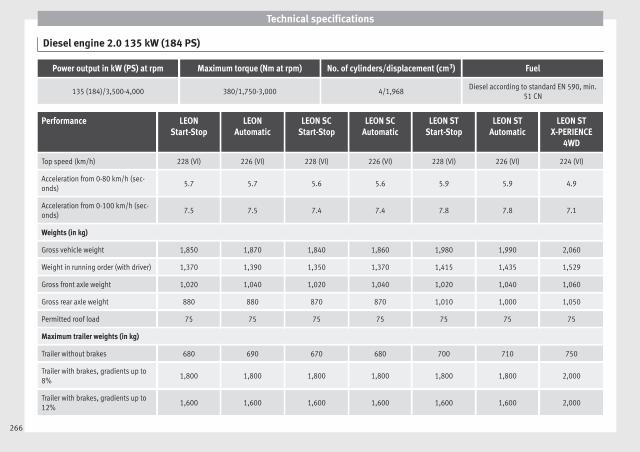
Technical specifications
Diesel engine 2.0 135 kW (184 PS)
Power output in kW (PS) at rpm Maximum torque (Nm at rpm) No. of cylinders/displacement (cm3) Fuel
135 (184)/3,500-4,000 380/1,750-3,000 4/1,968Diesel according to standard EN 590, min.
51 CN
Performance LEONStart-Stop
LEONAutomatic
LEON SCStart-Stop
LEON SCAutomatic
LEON STStart-Stop
LEON STAutomatic
LEON STX-PERIENCE
4WD
Top speed (km/h) 228 (VI) 226 (VI) 228 (VI) 226 (VI) 228 (VI) 226 (VI) 224 (VI)
Acceleration from 0-80 km/h (sec-onds)
5.7 5.7 5.6 5.6 5.9 5.9 4.9
Acceleration from 0-100 km/h (sec-onds)
7.5 7.5 7.4 7.4 7.8 7.8 7.1
Weights (in kg)
Gross vehicle weight 1,850 1,870 1,840 1,860 1,980 1,990 2,060
Weight in running order (with driver) 1,370 1,390 1,350 1,370 1,415 1,435 1,529
Gross front axle weight 1,020 1,040 1,020 1,040 1,020 1,040 1,060
Gross rear axle weight 880 880 870 870 1,010 1,000 1,050
Permitted roof load 75 75 75 75 75 75 75
Maximum trailer weights (in kg)
Trailer without brakes 680 690 670 680 700 710 750
Trailer with brakes, gradients up to8%
1,800 1,800 1,800 1,800 1,800 1,800 2,000
Trailer with brakes, gradients up to12%
1,600 1,600 1,600 1,600 1,600 1,600 2,000
266

Technical specifications
Dimensions
Fig. 227 Dimensions
LEON LEON SC LEON ST LEON ST X-PERIENCE
A/B Front and rear projection (mm) 853/774 853/774 853/1,046 853/1,060
C Wheelbase (mm) 2,636 2,601 2,636 2,630
D Length (mm) 4,263 4,228 4,535 4,543
E/F Front/reara) track width (mm)1,533/1,5041,549/1,520
1,541/1,5471,504/1,510
G Width (mm) 1,816 1,810 1,816 1,816
H Height at kerb weight (mm) 1,459 1,446 1,454b) 1,481b)
Turning radius (m) 10.9
a) This data will change depending on the type of wheel rim.b) Dimension to the roof bars.
267
Tech
nical
spec
ificati
ons
Adv
ice
Ope
rati
onS
afet
yTh
e es
sent
ials

Technical specifications
Filling capacities
Tank level
Petrol and diesel engines50 l, of which, approx. 7 l reserve
Vehicles with all-wheel-drive:55 l, of which, approx. 8.5 l reserve
Natural gas enginea) approx. 15 kg
Windscreen washer fluid containerapprox. 3 litres in versions without headlight washers
approx. 5 litres in versions with headlight washers
Tyre pressure
Summer tyres:Correct tyre pressure can be seen on the sticker on the inside of the fuel tank flap.
Winter tyres:The pressure of these tyres is 0.2 bar higher than that of summer tyres (2.9 psi / 20 kPa).
a) The capacity depends on the efficacy and characteristics of the natural gas pumps. The capacity indicated is based on a minimum loading pressure of 200 bar.
268

Index
Index
AABS
see Anti-lock brake system . . . . . . . . . . . . . . . 143ACC . . . . . . . . . . . . . . . . . . . . . . . . . . . . . . . . . . . . 151
radar sensor . . . . . . . . . . . . . . . . . . . . . . . . . . . 153Accessories . . . . . . . . . . . . . . . . . . . . . . . . . . . . . . 113Acoustic parking aid . . . . . . . . . . . . . . . . . . . . . . 173Adaptive cruise control
control lamp . . . . . . . . . . . . . . . . . . . . . . . . . . . 152malfunction . . . . . . . . . . . . . . . . . . . . . . . . . . . . 152messages on the display . . . . . . . . . . . . . . . . . 152radar sensor . . . . . . . . . . . . . . . . . . . . . . . . . . . 153special driving situations . . . . . . . . . . . . . . . . . 159warning lamp . . . . . . . . . . . . . . . . . . . . . . . . . . 152
Adaptive Cruise Control . . . . . . . . . . . . . . . . . . . . 151deactivating temporarily . . . . . . . . . . . . . . . . . 158operating . . . . . . . . . . . . . . . . . . . . . . . . . . . . . . 154
Additional electrical appliances (efficiency pro-gramme) . . . . . . . . . . . . . . . . . . . . . . . . . . . . . . . 77
Adjustingfront head restraints . . . . . . . . . . . . . . . . . . . . . 107front seats . . . . . . . . . . . . . . . . . . . . . . . . . . . . . 106rear head restraints . . . . . . . . . . . . . . . . . . . . . 107
Adjusting the head restraintsFront head restraints . . . . . . . . . . . . . . . . . . . . 107
Airbag . . . . . . . . . . . . . . . . . . . . . . . . . . . . . . . . . . . 48Airbag covers . . . . . . . . . . . . . . . . . . . . . . . . . . . . . 50Airbags
description . . . . . . . . . . . . . . . . . . . . . . . . . . . . . 49Airbag system . . . . . . . . . . . . . . . . . . . . . . . . . . . . . 48
activation . . . . . . . . . . . . . . . . . . . . . . . . . . . . . . 49Differences between front passenger front air-
bag systems . . . . . . . . . . . . . . . . . . . . . . . . . . 51disabling the front airbag . . . . . . . . . . . . . . . . . 54
front airbags . . . . . . . . . . . . . . . . . . . . . . . . . . . . 50functioning . . . . . . . . . . . . . . . . . . . . . . . . . . . . . 49head-protection airbags . . . . . . . . . . . . . . . . . . 53Knee airbag . . . . . . . . . . . . . . . . . . . . . . . . . . . . . 52side airbags . . . . . . . . . . . . . . . . . . . . . . . . . . . . 52
Air conditioning . . . . . . . . . . . . . . . . . . . . . . . . 26, 28Air pressure (tyres) . . . . . . . . . . . . . . . . . . . . . . . . 208Alarm system . . . . . . . . . . . . . . . . . . . . . . . . . . . . . 87Alcantara: cleaning . . . . . . . . . . . . . . . . . . . . . . . 189All-wheel drive
Snow chains . . . . . . . . . . . . . . . . . . . . . . . . . . . 191Winter tyres . . . . . . . . . . . . . . . . . . . . . . . . . . . . 191
Ambient lighting . . . . . . . . . . . . . . . . . . . . . . . . . 101Anti-dazzle interior mirror . . . . . . . . . . . . . . . . . . 104Anti-dazzle rear vision mirror . . . . . . . . . . . . . . . . 104Anti-lock brake system . . . . . . . . . . . . . . . . . . . . . 143Anti-puncture . . . . . . . . . . . . . . . . . . . . . . . . . . . . . 33Anti-puncture kit . . . . . . . . . . . . . . . . . . . . . . . . . . . 33Anti-theft alarm . . . . . . . . . . . . . . . . . . . . . . . . 82, 87
see also Anti-theft alarm system . . . . . . . . . . . . 82Anti-theft alarm system
Interior monitoring . . . . . . . . . . . . . . . . . . . . . . . 89Tow-away protection . . . . . . . . . . . . . . . . . . . . . . 89
Anti-theft security system . . . . . . . . . . . 82, 85, 227Anti-theft wheel bolts . . . . . . . . . . . . . . . . . . . . . 218Anti-trap function
Sliding panoramic sunroof . . . . . . . . . . . . . . . . 93sun blind . . . . . . . . . . . . . . . . . . . . . . . . . . . . . . . 93
Anti-trap function slidingAnti-trap function . . . . . . . . . . . . . . . . . . . . . . . . 93
Antifreeze . . . . . . . . . . . . . . . . . . . . . . . . . . . . . . . 203Aspects to take into account before starting the
vehicle . . . . . . . . . . . . . . . . . . . . . . . . . . . . . . . . . 37ASR
see Traction control system . . . . . . . . . . . . . . . 143Assistance systems . . . . . . . . . . . . . . . . . . . . . . . 150
ACC . . . . . . . . . . . . . . . . . . . . . . . . . . . . . . . . . . 151adaptive cruise control . . . . . . . . . . . . . . . . . . . 151
Cruise control . . . . . . . . . . . . . . . . . . . . . . . . . . 150Parking aid . . . . . . . . . . . . . . . . . . . . . . . . . . . . 174
Assisted starting . . . . . . . . . . . . . . . . . . . . . . . . . 223Assist systems
Tyre monitoring indicator . . . . . . . . . . . . . . . . . 213Audible warnings
Lights . . . . . . . . . . . . . . . . . . . . . . . . . . . . . . . . . 94Audible warning signal . . . . . . . . . . . . . . . . . . . . . 43Auto Lock (central locking) . . . . . . . . . . . . . . . . . . 82Automatic car washes
see Washing . . . . . . . . . . . . . . . . . . . . . . . . . . . 183Automatic dipped beam control . . . . . . . . . . . . . . 96Automatic gearbox . . . . . . . . . . . . . . . . . . . . . . . . 132
Backup programme . . . . . . . . . . . . . . . . . . . . . 139Downhill speed control . . . . . . . . . . . . . . . . . . 138Driving tips . . . . . . . . . . . . . . . . . . . . . . . . . . . . 136Kick-down feature . . . . . . . . . . . . . . . . . . . . . . . 137Launch Control Programme . . . . . . . . . . . . . . . 137Manual release of selector lever . . . . . . . . . . . 229Safety interlock for ignition key . . . . . . . . . . . . 129Selector lever lock . . . . . . . . . . . . . . . . . . . . . . 134Selector lever positions . . . . . . . . . . . . . . . . . . 133Steering wheel with gearshift paddles . . . . . . 135tiptronic . . . . . . . . . . . . . . . . . . . . . . . . . . 132, 135
Automatic gear change . . . . . . . . . . . . . . . . . . . . . 25
BBalanced (wheels) . . . . . . . . . . . . . . . . . . . . . . . . 208Ball coupling . . . . . . . . . . . . . . . . . . . . . . . . . . . . . 179Battery . . . . . . . . . . . . . . . . . . . . . . . . . . . 33, 86, 205
Assisted starting . . . . . . . . . . . . . . . . . . . . . . . . 223Charge Level . . . . . . . . . . . . . . . . . . . . . . . . . . . 191Charging . . . . . . . . . . . . . . . . . . . . . . . . . . . . . . 206Disconnecting/Connecting . . . . . . . . . . . . . . . 205Power Management . . . . . . . . . . . . . . . . . . . . . 191Replacement . . . . . . . . . . . . . . . . . . . . . . . . . . . 207Winter conditions . . . . . . . . . . . . . . . . . . . . . . . 205
269

Index
Before starting the vehicle . . . . . . . . . . . . . . . . . . 37Belt tightening . . . . . . . . . . . . . . . . . . . . . . . . . . . . 47Bench seat . . . . . . . . . . . . . . . . . . . . . . . . . . . . . . 110Biodiesel . . . . . . . . . . . . . . . . . . . . . . . . . . . . . . . . 196Bonnet . . . . . . . . . . . . . . . . . . . . . . . . . . . . . 10, 198Brake fluid . . . . . . . . . . . . . . . . . . . . . . . . . . . . . . . 32Brakes . . . . . . . . . . . . . . . . . . . . . . . . . . . . . . . . . . 146
Brake fluid . . . . . . . . . . . . . . . . . . . . . . . . . . . . . 204Brake servo . . . . . . . . . . . . . . . . . . . . . . . . . . . . 146New brake pads . . . . . . . . . . . . . . . . . . . . . . . . 146
BrakingBrake assist system . . . . . . . . . . . . . . . . . . . . . 143Moving off on hills . . . . . . . . . . . . . . . . . . . . . . 147
CCarbon components: Cleaning . . . . . . . . . . . . . . 186Care . . . . . . . . . . . . . . . . . . . . . . . . . . . . . . . . . . . . 183Care of vehicle . . . . . . . . . . . . . . . . . . . . . . . . . . . 183Care (paint care) . . . . . . . . . . . . . . . . . . . . . . . . . . 185CAR menu Setup . . . . . . . . . . . . . . . . . . . . . . . . . . . 17Catalytic converter . . . . . . . . . . . . . . . . . . . . . . . . 141CCS . . . . . . . . . . . . . . . . . . . . . . . . . . . . . . . . . . . . . 21CD-ROM player (navigation) . . . . . . . . . . . . . . . . 112Central locking
Anti-theft alarm . . . . . . . . . . . . . . . . . . . . . . . . . . 87Central locking switch . . . . . . . . . . . . . . . . . . . . 85Electric windows . . . . . . . . . . . . . . . . . . . . . . . . . 91Manual locking . . . . . . . . . . . . . . . . . . . . . . . . . 228Programming . . . . . . . . . . . . . . . . . . . . . . . . . . . 85Rear lid . . . . . . . . . . . . . . . . . . . . . . . . . . . . . . . . 89Remote control key . . . . . . . . . . . . . . . . . . . . . . . 84Selective unlocking system . . . . . . . . . . . . . . . . 84Sliding/tilting sunroof . . . . . . . . . . . . . . . . . . . . 91
Central locking system . . . . . . . . . . . . . . . . . . . . . . 82Cetane number (diesel fuel) . . . . . . . . . . . . . . . . 196
Changingof windscreen wiper and window washer
blades . . . . . . . . . . . . . . . . . . . . . . . . . . . . . . 230Changing a bulb . . . . . . . . . . . . . . . . . . . . . . . . . . 233
Bulb sizes . . . . . . . . . . . . . . . . . . . . . . . . . . . . . 233Changing gear
Engaging gears (manual gearbox) . . . . . . . . . 132Manual gearbox . . . . . . . . . . . . . . . . . . . . . . . . 132
Changing main headlightturn signal . . . . . . . . . . . . . . . . . . . . . . . . . . . . . 235
Changing the batteryof the vehicle key . . . . . . . . . . . . . . . . . . . . . . . . 86
Changing the main beam headlight bulbmain beam headlight . . . . . . . . . . . . . . . . . . . . 236
Changing the main headlight bulbday light . . . . . . . . . . . . . . . . . . . . . . . . . . . . . . 235dipped light . . . . . . . . . . . . . . . . . . . . . . . . . . . 235
Chassis number . . . . . . . . . . . . . . . . . . . . . . . . . . 241Child-proof lock
Electric windows . . . . . . . . . . . . . . . . . . . . . . . . . 90Child safety . . . . . . . . . . . . . . . . . . . . . . . . . . . . . . . 56Child seat
Categorisation in groups . . . . . . . . . . . . . . . . . . 58Child seats . . . . . . . . . . . . . . . . . . . . . . . . . . . . . . . 58
ISOFIX system . . . . . . . . . . . . . . . . . . . . . . . . . . . 59safety instructions . . . . . . . . . . . . . . . . . . . . . . . 57Top Tether system . . . . . . . . . . . . . . . . . . . . . 59, 61
City Emergency braking function . . . . . . . . . . . . . 165Cleaning . . . . . . . . . . . . . . . . . . . . . . . . . . . . . . . . 183
Alcantara . . . . . . . . . . . . . . . . . . . . . . . . . . . . . . 189Carbon components . . . . . . . . . . . . . . . . . . . . . 186Display/Easy Connect control panel . . . . . . . . 187Exhaust pipe . . . . . . . . . . . . . . . . . . . . . . . . . . . 186Leather . . . . . . . . . . . . . . . . . . . . . . . . . . . . . . . 188of Changing windscreen wiper and window
washer blades . . . . . . . . . . . . . . . . . . . . . . . . 230Plastic parts . . . . . . . . . . . . . . . . . . . . . . 185, 187Radio display . . . . . . . . . . . . . . . . . . . . . . . . . . 187
Seat belts . . . . . . . . . . . . . . . . . . . . . . . . . . . . . 189Trim parts . . . . . . . . . . . . . . . . . . . . . . . . . . . . . 187Trims . . . . . . . . . . . . . . . . . . . . . . . . . . . . . . . . . 185Washing the vehicle . . . . . . . . . . . . . . . . . . . . . 183Wheels . . . . . . . . . . . . . . . . . . . . . . . . . . . . . . . 186Windows . . . . . . . . . . . . . . . . . . . . . . . . . . . . . . 186
Cleaning/De-icing the windows . . . . . . . . . . . . . 186Cleaning the upholstery
Natural leather . . . . . . . . . . . . . . . . . . . . . . . . . 188Climatronic . . . . . . . . . . . . . . . . . . . . . . . . . . . . . . . 26Close . . . . . . . . . . . . . . . . . . . . . . . . . . . . . . . . . . . . 82
Panoramic sunroof . . . . . . . . . . . . . . . . . . . . . . . 92Windows . . . . . . . . . . . . . . . . . . . . . . . . . . . . . . . 90
Closing . . . . . . . . . . . . . . . . . . . . . . . . . . . . . . . . . . 82Bonnet . . . . . . . . . . . . . . . . . . . . . . . . . . . . . . . . 199Panoramic sliding sunroof . . . . . . . . . . . . . . . . . 92Panoramic sunroof . . . . . . . . . . . . . . . . . . . . . . . 92Windows . . . . . . . . . . . . . . . . . . . . . . . . . . . . . . . 90
Clutch (warning lamp) . . . . . . . . . . . . . . . . . . . . . 139Coming Home . . . . . . . . . . . . . . . . . . . . . . . . . . . . . 97Control lamp
Cruise control . . . . . . . . . . . . . . . . . . . . . . . . . . 150Tyre monitor indicator warning lamp . . . . . . . 212Tyre monitoring systems . . . . . . . . . . . . . . . . . 212
Control lampsAdaptive cruise control . . . . . . . . . . . . . . . . . . 152
Control of functionRain sensor . . . . . . . . . . . . . . . . . . . . . . . . . . . . 104
Controls and displays (overview) . . . . . . . . . . . . . 65Convenience closing
Panoramic sliding sunroof . . . . . . . . . . . . . . . . . 93Convenience opening
Panoramic sliding sunroof . . . . . . . . . . . . . . . . . 93Convenience opening/closing . . . . . . . . . . . . . . . 91Coolant . . . . . . . . . . . . . . . . . . . . . . . . . . . . . . . . . . 32
270

Index
Cooling systemChecking the coolant . . . . . . . . . . . . . . . . . . . . 203Coolant temperature gauge . . . . . . . . . . . . . . . . 69Topping up coolant . . . . . . . . . . . . . . . . . . . . . . 203
Cornering lights . . . . . . . . . . . . . . . . . . . . . . . . . . . 97Correct adjustment of front head restraints . . . . . 41Correct adjustment of rear head restraints
In-use and non-use positions of rear head re-straints . . . . . . . . . . . . . . . . . . . . . . . . . . . . . . 41
Correct sitting positionfront passenger . . . . . . . . . . . . . . . . . . . . . . . . . 39Incorrect sitting position . . . . . . . . . . . . . . . . . . 40passenger . . . . . . . . . . . . . . . . . . . . . . . . . . . . . . 40
Cruise control . . . . . . . . . . . . . . . . . . . . . . . . 21, 150Control lamp . . . . . . . . . . . . . . . . . . . . . . . . . . . 150Operation . . . . . . . . . . . . . . . . . . . . . . . . . . . . . 151Warning lamp . . . . . . . . . . . . . . . . . . . . . . . . . . 150
Cruise control system . . . . . . . . . . . . . . . . . . . . . . 150
DDangers in not using the seat belt . . . . . . . . . . . . 45Daytime driving light . . . . . . . . . . . . . . . . . . . . . . . 95Deactivating the front passenger front airbag . . . 11DEF (instrument panel) . . . . . . . . . . . . . . . . . . . . . 69Diesel
Diesel particulate filter . . . . . . . . . . . . . . . . . . . 141Engine oil . . . . . . . . . . . . . . . . . . . . . . . . . . . . . 200Pre-heating . . . . . . . . . . . . . . . . . . . . . . . . . . . . 129
Digital clock . . . . . . . . . . . . . . . . . . . . . . . . . . . . . . 66Dimensions . . . . . . . . . . . . . . . . . . . . . . . . . . . . . . 267Dipped beam headlight . . . . . . . . . . . . . . . . . . . . . 94Direction of rotation (tyres) . . . . . . . . . . . . . . . . . 220Disabling the front airbag . . . . . . . . . . . . . . . . . . . 54Display . . . . . . . . . . . . . . . . . . . . . . . . . . . . . . . 66, 67Display/Easy Connect control panel: cleaning . . 187Disposal
Seat belt tensioners . . . . . . . . . . . . . . . . . . . . . . 47
Distance controlsee Adaptive cruise control . . . . . . . . . . . . . . . 151
Door/rear lid warning . . . . . . . . . . . . . . . . . . . . . . . 72Door cylinder . . . . . . . . . . . . . . . . . . . . . . . . . . . . 227Door handle . . . . . . . . . . . . . . . . . . . . . . . . . . . . . 227Door lock . . . . . . . . . . . . . . . . . . . . . . . . . . . . . . . . 227Doors
Childproof locks . . . . . . . . . . . . . . . . . . . . . . . . . 87Opening and closing . . . . . . . . . . . . . . . . . . . . . . 9
Downhill speed control . . . . . . . . . . . . . . . . . . . . 138Drawer . . . . . . . . . . . . . . . . . . . . . . . . . . . . . . . . . . 111Drink holders . . . . . . . . . . . . . . . . . . . . . . . . . . . . 112Driver
see Correct sitting position . . . . . . . . . 38, 39, 40Driver information system . . . . . . . . . . . . . . . . . . . 19
CD/radio display . . . . . . . . . . . . . . . . . . . . . . . . . 72Control . . . . . . . . . . . . . . . . . . . . . . . . . . . . . . . . . 19Door/rear lid warning . . . . . . . . . . . . . . . . . . . . . 72Engine oil temperature display . . . . . . . . . . . . . 77Menu . . . . . . . . . . . . . . . . . . . . . . . . . . . . . . . . . . 20Operation via the windscreen wiper lever . . . . . 72Outside temperature display . . . . . . . . . . . . . . . 72
DrivingWith a trailer . . . . . . . . . . . . . . . . . . . . . . 177, 179
Driving abroadHeadlights . . . . . . . . . . . . . . . . . . . . . . . . . . . . 100
Driving mode . . . . . . . . . . . . . . . . . . . . . . . 170, 171Driving profile . . . . . . . . . . . . . . . . . . . . . . . 170, 171Driving safety . . . . . . . . . . . . . . . . . . . . . . . . . . . . . 37Driving through water . . . . . . . . . . . . . . . . . . . . . 141Dynamic headlight range control . . . . . . . . . . . . 100
EE10
see Ethanol (fuel) . . . . . . . . . . . . . . . . . . . . . . . 195Easy Connect . . . . . . . . . . . . . . . . . . . . . . . . . . 17, 81Economic driving . . . . . . . . . . . . . . . . . . . . . . . . . 142
EDLsee Electronic differential lock . . . . . . . . . . . . . 143
Efficiency programmeAdditional electrical appliances . . . . . . . . . . . . 77Saving tips . . . . . . . . . . . . . . . . . . . . . . . . . . . . . 78
ElectricWindows . . . . . . . . . . . . . . . . . . . . . . . . . . . . . . . 90
Electrical accessoriessee Power socket . . . . . . . . . . . . . . . . . . . . . . . 113
Electrical socketstrailer . . . . . . . . . . . . . . . . . . . . . . . . . . . . . . . . . 179
Electric seatAdjustment . . . . . . . . . . . . . . . . . . . . . . . . . . . . . 12
Electric windows . . . . . . . . . . . . . . . . . . . . . . . . 10, 90Convenience opening/closing . . . . . . . . . . . . . . 91
Electro-mechanical steering . . . . . . . . . . . . . . . . 190Warning lamp . . . . . . . . . . . . . . . . . . . . . . . . . . 190
Electronic differential lock . . . . . . . . . . . . . . . . . . 143Electronic self-locking . . . . . . . . . . . . . . . . . . . . . 143Electronic Stability Control (ESC) . . . . . . . . . . . . 143Emergencies . . . . . . . . . . . . . . . . . . . . . . . . . . . . . 217
Automatic gearbox Backup programme . . . . . 139Replacing the battery . . . . . . . . . . . . . . . . . . . . 207
Emergency braking warning . . . . . . . . . . . . . . . . . 99Emergency locking and unlocking . . . . . . . . . . . 227Emergency towing . . . . . . . . . . . . . . . . . . . . . . . . . 35Engine
Assisted starting . . . . . . . . . . . . . . . . . . . . . . . . 223Pre-heating . . . . . . . . . . . . . . . . . . . . . . . . . . . . 129Start-Stop system . . . . . . . . . . . . . . . . . . . . . . . 148Starting . . . . . . . . . . . . . . . . . . . . . . . . . . . . . . . 129Starting up (driver messages with the me-
chanical contact) . . . . . . . . . . . . . . . . . . . . . 129Switching off (engine) . . . . . . . . . . . . . . . . . . . 130
Engine compartment . . . . . . . . . . . . . . . . . . 10, 198Closing the bonnet . . . . . . . . . . . . . . . . . . . . . . 199Opening the bonnet . . . . . . . . . . . . . . . . . . . . . 199Safety notes . . . . . . . . . . . . . . . . . . . . . . . . . . . 198
271

Index
Engine coolant . . . . . . . . . . . . . . . . . . . . . . . . . . . 203G 12 plus-plus . . . . . . . . . . . . . . . . . . . . . . . . . 203G 13 . . . . . . . . . . . . . . . . . . . . . . . . . . . . . . . . . . 203Specifications . . . . . . . . . . . . . . . . . . . . . . . . . . 203
Engine faultcontrol lamp . . . . . . . . . . . . . . . . . . . . . . . . . . . . 71
Engine managementcontrol lamp . . . . . . . . . . . . . . . . . . . . . . . . . . . . 71
Engine oil . . . . . . . . . . . . . . . . . . . . . . . . . . . . . . . 200Changing . . . . . . . . . . . . . . . . . . . . . . . . . . . . . . 202Checking oil level . . . . . . . . . . . . . . . . . . . . . . . 201Consumption . . . . . . . . . . . . . . . . . . . . . . . . . . 201Engine oil dipstick . . . . . . . . . . . . . . . . . . . . . . 201Inspection service . . . . . . . . . . . . . . . . . . . . . . 200Longlife inspection service . . . . . . . . . . . . . . . 200Oil properties . . . . . . . . . . . . . . . . . . . . . . . . . . 201Replace . . . . . . . . . . . . . . . . . . . . . . . . . . . . . . . 200Service intervals . . . . . . . . . . . . . . . . . . . . . . . . 200Specifications . . . . . . . . . . . . . . . . . . . . . . . . . . 200Temperature display . . . . . . . . . . . . . . . . . . . . . . 77Topping up . . . . . . . . . . . . . . . . . . . . . . . . . . . . 202
EnvironmentEcological driving . . . . . . . . . . . . . . . . . . . . . . . 142Environmental friendliness . . . . . . . . . . . . . . . 140
Environmental tipLeaks . . . . . . . . . . . . . . . . . . . . . . . . . . . . . . . . . 199
Environmental tipsFilling the tank . . . . . . . . . . . . . . . . . . . . . . . . . 194Refuelling . . . . . . . . . . . . . . . . . . . . . . . . . . . . . 193
Environment warning . . . . . . . . . . . . . . . . . . . . . . 174Equipment . . . . . . . . . . . . . . . . . . . . . . . . . . . . . . 113ESC
Electronic stability control . . . . . . . . . . . . . . . . 143Multi-collision brake . . . . . . . . . . . . . . . . . . . . . 144Sport Mode . . . . . . . . . . . . . . . . . . . . . . . . . . . . 145
Ethanol (fuel) . . . . . . . . . . . . . . . . . . . . . . . . . . . . 195
Exhaust gas filtration systemCatalytic converter . . . . . . . . . . . . . . . . . . . . . . 141
Exhaust tail pipe: Cleaning . . . . . . . . . . . . . . . . . 186Extending
the luggage compartment . . . . . . . . . . . . . . . . 109Exterior lighting
Changing a bulb . . . . . . . . . . . . . . . . . . . . . . . . 233Exterior mirrors
adjusting . . . . . . . . . . . . . . . . . . . . . . . . . . . . . . 104Adjusting . . . . . . . . . . . . . . . . . . . . . . . . . . . . . . . 13
Exterior view . . . . . . . . . . . . . . . . . . . . . . . . . . . . . . . 5
FFastening rings . . . . . . . . . . . . . . . . . . . . . . . . . . . 119Fault in the gearbox (warning lamp) . . . . . . . . . . 139Faults
Panoramic sliding sunroof . . . . . . . . . . . . . . . . . 93Faults in the gearbox (warning lamps) . . . . . . . . 139Faulty bulbs
Changing a bulb . . . . . . . . . . . . . . . . . . . . . . . . 233Filling the fuel tank . . . . . . . . . . . . . . . . . . . . . . . 193Floor mats . . . . . . . . . . . . . . . . . . . . . . . . . . . . . . . . 42Fog light . . . . . . . . . . . . . . . . . . . . . . . . . . . . . . . . . 97Folding down the back seats . . . . . . . . . . . . . . . . 109Folding table . . . . . . . . . . . . . . . . . . . . . . . . . . . . . 111Four wheel drive . . . . . . . . . . . . . . . . . . . . . . . . . . 191Front airbags . . . . . . . . . . . . . . . . . . . . . . . . . . . . . 50Front armrest . . . . . . . . . . . . . . . . . . . . . . . . . . . . 108Front Assist
City Emergency braking function . . . . . . . . . . . 165malfunction . . . . . . . . . . . . . . . . . . . . . . . . . . . . 162on-screen messages . . . . . . . . . . . . . . . . . . . . 162operating . . . . . . . . . . . . . . . . . . . . . . . . . . . . . . 163radar sensor . . . . . . . . . . . . . . . . . . . . . . . . . . . 163switching off temporarily . . . . . . . . . . . . . . . . . 164system limitations . . . . . . . . . . . . . . . . . . . . . . 164see also Front Assist Monitoring system . . . . . 161
Front Assist monitoring systemmalfunction . . . . . . . . . . . . . . . . . . . . . . . . . . . . 162on-screen messages . . . . . . . . . . . . . . . . . . . . 162operating . . . . . . . . . . . . . . . . . . . . . . . . . . . . . . 163
Front Assist Monitoring system . . . . . . . . . . . . . . 161City Emergency braking function . . . . . . . . . . . 165radar sensor . . . . . . . . . . . . . . . . . . . . . . . . . . . 163
Front Assist Monitoring Systemswitching off temporarily . . . . . . . . . . . . . . . . . 164system limitations . . . . . . . . . . . . . . . . . . . . . . 164
Front head restraints . . . . . . . . . . . . . . . . . . . . . . . 41Front headrests . . . . . . . . . . . . . . . . . . . . . . . . . . . 41Front passenger front airbag
Deactivating . . . . . . . . . . . . . . . . . . . . . . . . . . . . 11Front seats
Manually adjusting . . . . . . . . . . . . . . . . . . . . . . . 12Fuel . . . . . . . . . . . . . . . . . . . . . . . . . . . . . . . . 31, 195
Consumption . . . . . . . . . . . . . . . . . . . . . . . . . . 241diesel . . . . . . . . . . . . . . . . . . . . . . . . . . . . . . . . . 196Ethanol . . . . . . . . . . . . . . . . . . . . . . . . . . . . . . . 195Fuel gauge . . . . . . . . . . . . . . . . . . . . . . . . . . . . . 70natural gas . . . . . . . . . . . . . . . . . . . . . . . . . . . . 196
Fuel consumption . . . . . . . . . . . . . . . . . . . . . . . . . 242Fuel tank cap
Opening and closing . . . . . . . . . . . . . . . . . . . . . 31Fuel tank flap
Opening and closing . . . . . . . . . . . . . . . . . . . . . 31Full-LED headlights . . . . . . . . . . . . . . . . . . . . . . . 233Fuses . . . . . . . . . . . . . . . . . . . . . . . . . . . . . . . 33, 231
Fuse box . . . . . . . . . . . . . . . . . . . . . . . . . . . . . . 232Identifying blown fuses . . . . . . . . . . . . . . . . . . 233Identifying by colours . . . . . . . . . . . . . . . . . . . . 232Preparation before replacing . . . . . . . . . . . . . . 233Replacement . . . . . . . . . . . . . . . . . . . . . . . . . . . 233
272
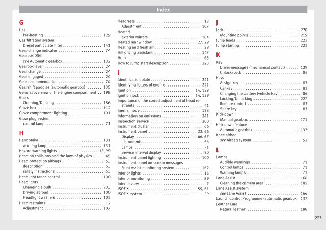
Index
GGas
Pre-heating . . . . . . . . . . . . . . . . . . . . . . . . . . . . 129Gas filtration system
Diesel particulate filter . . . . . . . . . . . . . . . . . . . 141Gear-change indicator . . . . . . . . . . . . . . . . . . . . . . 74Gearbox DSG
see Automatic gearbox . . . . . . . . . . . . . . . . . . . 132Gearbox lever . . . . . . . . . . . . . . . . . . . . . . . . . . . . . 24Gear change . . . . . . . . . . . . . . . . . . . . . . . . . . . . . . 24Gear engaged . . . . . . . . . . . . . . . . . . . . . . . . . . . . . 24Gear recommendation . . . . . . . . . . . . . . . . . . . . . . 74Gearshift paddles (automatic gearbox) . . . . . . . 135General overview of the engine compartment . . 198Glass
Cleaning/De-icing . . . . . . . . . . . . . . . . . . . . . . 186Glove box . . . . . . . . . . . . . . . . . . . . . . . . . . . . . . . 112Glove compartment lighting . . . . . . . . . . . . . . . . 101Glow plug system
control lamp . . . . . . . . . . . . . . . . . . . . . . . . . . . . 71
HHandbrake . . . . . . . . . . . . . . . . . . . . . . . . . . . . . . 131
warning lamp . . . . . . . . . . . . . . . . . . . . . . . . . . 131Hazard warning lights . . . . . . . . . . . . . . . . . . . 15, 99Head-on collisions and the laws of physics . . . . . 45Head-protection airbags . . . . . . . . . . . . . . . . . . . . 53
description . . . . . . . . . . . . . . . . . . . . . . . . . . . . . 53safety instructions . . . . . . . . . . . . . . . . . . . . . . . 53
Headlight range control . . . . . . . . . . . . . . . . . . . . 100Headlights
Changing a bulb . . . . . . . . . . . . . . . . . . . . . . . . 233Driving abroad . . . . . . . . . . . . . . . . . . . . . . . . . 100Headlight washers . . . . . . . . . . . . . . . . . . . . . . 103
Head restraints . . . . . . . . . . . . . . . . . . . . . . . . . . . . 12Adjustment . . . . . . . . . . . . . . . . . . . . . . . . . . . . 107
Headrests . . . . . . . . . . . . . . . . . . . . . . . . . . . . . . . . 12Adjustment . . . . . . . . . . . . . . . . . . . . . . . . . . . . 107
Heatedexterior mirrors . . . . . . . . . . . . . . . . . . . . . . . . . 104
Heated rear window . . . . . . . . . . . . . . . . . . . . . 27, 29Heating and fresh air . . . . . . . . . . . . . . . . . . . . . . . 29Hill driving assistant . . . . . . . . . . . . . . . . . . . . . . 147Horn . . . . . . . . . . . . . . . . . . . . . . . . . . . . . . . . . . . . 65How to jump start description . . . . . . . . . . . . . . . 223
IIdentification plate . . . . . . . . . . . . . . . . . . . . . . . . 241Identifying letters of engine . . . . . . . . . . . . . . . . 241Ignition . . . . . . . . . . . . . . . . . . . . . . . . . . . . . 14, 129Ignition lock . . . . . . . . . . . . . . . . . . . . . . . . . 14, 129Importance of the correct adjustment of head re-
straints . . . . . . . . . . . . . . . . . . . . . . . . . . . . . . . . 41Inertia mode . . . . . . . . . . . . . . . . . . . . . . . . . . . . . 138Information on emissions . . . . . . . . . . . . . . . . . . 241Inspection service . . . . . . . . . . . . . . . . . . . . . . . . 200Instrument cluster . . . . . . . . . . . . . . . . . . . . . . . . . 66Instrument panel . . . . . . . . . . . . . . . . . . . . . . . 22, 66
Display . . . . . . . . . . . . . . . . . . . . . . . . . . . . . 66, 67Instruments . . . . . . . . . . . . . . . . . . . . . . . . . . . . . 66Lamps . . . . . . . . . . . . . . . . . . . . . . . . . . . . . . . . . 71Service interval display . . . . . . . . . . . . . . . . . . . 80
Instrument panel lighting . . . . . . . . . . . . . . . . . . 100Instrument panel on-screen messages
Front Assist monitoring system . . . . . . . . . . . . 162Interior lights . . . . . . . . . . . . . . . . . . . . . . . . . . . . . 16Interior monitoring . . . . . . . . . . . . . . . . . . . . . . . . . 89Interior view . . . . . . . . . . . . . . . . . . . . . . . . . . . . . . . 7ISOFIX . . . . . . . . . . . . . . . . . . . . . . . . . . . . . . . . 59, 61ISOFIX system . . . . . . . . . . . . . . . . . . . . . . . . . . . . . 59
JJack . . . . . . . . . . . . . . . . . . . . . . . . . . . . . . . . . . . . 220
Mounting points . . . . . . . . . . . . . . . . . . . . . . . . 219Jump leads . . . . . . . . . . . . . . . . . . . . . . . . . . . . . . 223Jump starting . . . . . . . . . . . . . . . . . . . . . . . . . . . . 223
KKey
Driver messages (mechanical contact) . . . . . . 129Unlock/Lock . . . . . . . . . . . . . . . . . . . . . . . . . . . . 84
KeysAssign key . . . . . . . . . . . . . . . . . . . . . . . . . . . . . . 83Car key . . . . . . . . . . . . . . . . . . . . . . . . . . . . . . . . . 83Changing the battery (vehicle key) . . . . . . . . . . 86Locking/Unlocking . . . . . . . . . . . . . . . . . . . . . . 227Remote control . . . . . . . . . . . . . . . . . . . . . . . . . . 83Spare key . . . . . . . . . . . . . . . . . . . . . . . . . . . . . . 83
Kick-downManual gearbox . . . . . . . . . . . . . . . . . . . . . . . . 171
Kick-down featureAutomatic gearbox . . . . . . . . . . . . . . . . . . . . . . 137
Knee airbagsee Airbag system . . . . . . . . . . . . . . . . . . . . . . . 52
LLamps
Audible warnings . . . . . . . . . . . . . . . . . . . . . . . . 71Control lamps . . . . . . . . . . . . . . . . . . . . . . . . . . . 71Warning lamps . . . . . . . . . . . . . . . . . . . . . . . . . . 71
Lane Assist . . . . . . . . . . . . . . . . . . . . . . . . . . . . . . 166Cleaning the camera area . . . . . . . . . . . . . . . . 185
Lane Assist systemsee Lane Assist . . . . . . . . . . . . . . . . . . . . . . . . . 166
Launch Control Programme (automatic gearbox) 137Leather Care
Natural leather . . . . . . . . . . . . . . . . . . . . . . . . . 188
273
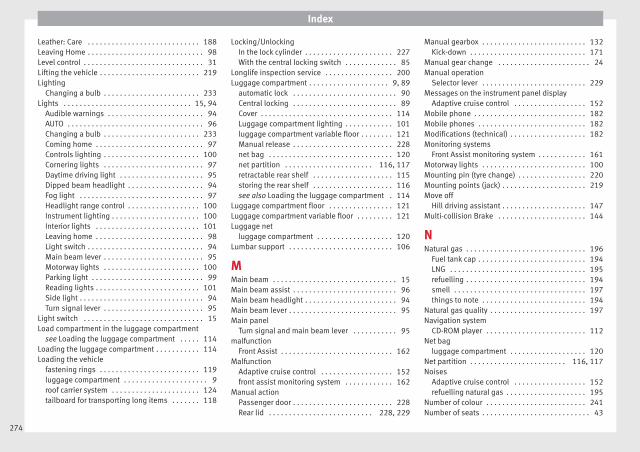
Index
Leather: Care . . . . . . . . . . . . . . . . . . . . . . . . . . . . 188Leaving Home . . . . . . . . . . . . . . . . . . . . . . . . . . . . . 98Level control . . . . . . . . . . . . . . . . . . . . . . . . . . . . . . 31Lifting the vehicle . . . . . . . . . . . . . . . . . . . . . . . . . 219Lighting
Changing a bulb . . . . . . . . . . . . . . . . . . . . . . . . 233Lights . . . . . . . . . . . . . . . . . . . . . . . . . . . . . . . . 15, 94
Audible warnings . . . . . . . . . . . . . . . . . . . . . . . . 94AUTO . . . . . . . . . . . . . . . . . . . . . . . . . . . . . . . . . . 96Changing a bulb . . . . . . . . . . . . . . . . . . . . . . . . 233Coming home . . . . . . . . . . . . . . . . . . . . . . . . . . . 97Controls lighting . . . . . . . . . . . . . . . . . . . . . . . . 100Cornering lights . . . . . . . . . . . . . . . . . . . . . . . . . 97Daytime driving light . . . . . . . . . . . . . . . . . . . . . 95Dipped beam headlight . . . . . . . . . . . . . . . . . . . 94Fog light . . . . . . . . . . . . . . . . . . . . . . . . . . . . . . . 97Headlight range control . . . . . . . . . . . . . . . . . . 100Instrument lighting . . . . . . . . . . . . . . . . . . . . . . 100Interior lights . . . . . . . . . . . . . . . . . . . . . . . . . . 101Leaving home . . . . . . . . . . . . . . . . . . . . . . . . . . . 98Light switch . . . . . . . . . . . . . . . . . . . . . . . . . . . . . 94Main beam lever . . . . . . . . . . . . . . . . . . . . . . . . . 95Motorway lights . . . . . . . . . . . . . . . . . . . . . . . . 100Parking light . . . . . . . . . . . . . . . . . . . . . . . . . . . . 99Reading lights . . . . . . . . . . . . . . . . . . . . . . . . . . 101Side light . . . . . . . . . . . . . . . . . . . . . . . . . . . . . . . 94Turn signal lever . . . . . . . . . . . . . . . . . . . . . . . . . 95
Light switch . . . . . . . . . . . . . . . . . . . . . . . . . . . . . . 15Load compartment in the luggage compartment
see Loading the luggage compartment . . . . . 114Loading the luggage compartment . . . . . . . . . . . 114Loading the vehicle
fastening rings . . . . . . . . . . . . . . . . . . . . . . . . . 119luggage compartment . . . . . . . . . . . . . . . . . . . . . 9roof carrier system . . . . . . . . . . . . . . . . . . . . . . 124tailboard for transporting long items . . . . . . . 118
Locking/UnlockingIn the lock cylinder . . . . . . . . . . . . . . . . . . . . . . 227With the central locking switch . . . . . . . . . . . . . 85
Longlife inspection service . . . . . . . . . . . . . . . . . 200Luggage compartment . . . . . . . . . . . . . . . . . . . . 9, 89
automatic lock . . . . . . . . . . . . . . . . . . . . . . . . . . 90Central locking . . . . . . . . . . . . . . . . . . . . . . . . . . 89Cover . . . . . . . . . . . . . . . . . . . . . . . . . . . . . . . . . 114Luggage compartment lighting . . . . . . . . . . . . 101luggage compartment variable floor . . . . . . . . 121Manual release . . . . . . . . . . . . . . . . . . . . . . . . . 228net bag . . . . . . . . . . . . . . . . . . . . . . . . . . . . . . . 120net partition . . . . . . . . . . . . . . . . . . . . . . 116, 117retractable rear shelf . . . . . . . . . . . . . . . . . . . . 115storing the rear shelf . . . . . . . . . . . . . . . . . . . . 116see also Loading the luggage compartment . 114
Luggage compartment floor . . . . . . . . . . . . . . . . 121Luggage compartment variable floor . . . . . . . . . 121Luggage net
luggage compartment . . . . . . . . . . . . . . . . . . . 120Lumbar support . . . . . . . . . . . . . . . . . . . . . . . . . . 106
MMain beam . . . . . . . . . . . . . . . . . . . . . . . . . . . . . . . 15Main beam assist . . . . . . . . . . . . . . . . . . . . . . . . . . 96Main beam headlight . . . . . . . . . . . . . . . . . . . . . . . 94Main beam lever . . . . . . . . . . . . . . . . . . . . . . . . . . . 95Main panel
Turn signal and main beam lever . . . . . . . . . . . 95malfunction
Front Assist . . . . . . . . . . . . . . . . . . . . . . . . . . . . 162Malfunction
Adaptive cruise control . . . . . . . . . . . . . . . . . . 152front assist monitoring system . . . . . . . . . . . . 162
Manual actionPassenger door . . . . . . . . . . . . . . . . . . . . . . . . . 228Rear lid . . . . . . . . . . . . . . . . . . . . . . . . . . 228, 229
Manual gearbox . . . . . . . . . . . . . . . . . . . . . . . . . . 132Kick-down . . . . . . . . . . . . . . . . . . . . . . . . . . . . . 171
Manual gear change . . . . . . . . . . . . . . . . . . . . . . . 24Manual operation
Selector lever . . . . . . . . . . . . . . . . . . . . . . . . . . 229Messages on the instrument panel display
Adaptive cruise control . . . . . . . . . . . . . . . . . . 152Mobile phone . . . . . . . . . . . . . . . . . . . . . . . . . . . . 182Mobile phones . . . . . . . . . . . . . . . . . . . . . . . . . . . 182Modifications (technical) . . . . . . . . . . . . . . . . . . . 182Monitoring systems
Front Assist monitoring system . . . . . . . . . . . . 161Motorway lights . . . . . . . . . . . . . . . . . . . . . . . . . . 100Mounting pin (tyre change) . . . . . . . . . . . . . . . . . 220Mounting points (jack) . . . . . . . . . . . . . . . . . . . . . 219Move off
Hill driving assistant . . . . . . . . . . . . . . . . . . . . . 147Multi-collision Brake . . . . . . . . . . . . . . . . . . . . . . 144
NNatural gas . . . . . . . . . . . . . . . . . . . . . . . . . . . . . . 196
Fuel tank cap . . . . . . . . . . . . . . . . . . . . . . . . . . . 194LNG . . . . . . . . . . . . . . . . . . . . . . . . . . . . . . . . . . 195refuelling . . . . . . . . . . . . . . . . . . . . . . . . . . . . . . 194smell . . . . . . . . . . . . . . . . . . . . . . . . . . . . . . . . . 197things to note . . . . . . . . . . . . . . . . . . . . . . . . . . 194
Natural gas quality . . . . . . . . . . . . . . . . . . . . . . . . 197Navigation system
CD-ROM player . . . . . . . . . . . . . . . . . . . . . . . . . 112Net bag
luggage compartment . . . . . . . . . . . . . . . . . . . 120Net partition . . . . . . . . . . . . . . . . . . . . . . . . 116, 117Noises
Adaptive cruise control . . . . . . . . . . . . . . . . . . 152refuelling natural gas . . . . . . . . . . . . . . . . . . . . 195
Number of colour . . . . . . . . . . . . . . . . . . . . . . . . . 241Number of seats . . . . . . . . . . . . . . . . . . . . . . . . . . . 43
274
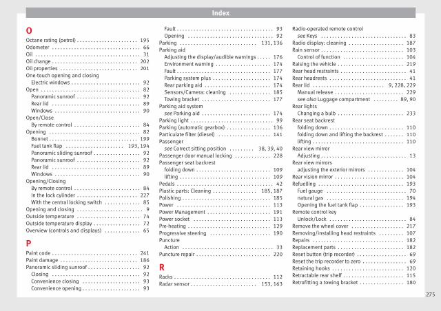
Index
OOctane rating (petrol) . . . . . . . . . . . . . . . . . . . . . . 195Odometer . . . . . . . . . . . . . . . . . . . . . . . . . . . . . . . . 66Oil . . . . . . . . . . . . . . . . . . . . . . . . . . . . . . . . . . . . . . 31Oil change . . . . . . . . . . . . . . . . . . . . . . . . . . . . . . . 202Oil properties . . . . . . . . . . . . . . . . . . . . . . . . . . . . 201One-touch opening and closing
Electric windows . . . . . . . . . . . . . . . . . . . . . . . . . 92Open . . . . . . . . . . . . . . . . . . . . . . . . . . . . . . . . . . . . 82
Panoramic sunroof . . . . . . . . . . . . . . . . . . . . . . . 92Rear lid . . . . . . . . . . . . . . . . . . . . . . . . . . . . . . . . 89Windows . . . . . . . . . . . . . . . . . . . . . . . . . . . . . . . 90
Open/CloseBy remote control . . . . . . . . . . . . . . . . . . . . . . . . 84
Opening . . . . . . . . . . . . . . . . . . . . . . . . . . . . . . . . . 82Bonnet . . . . . . . . . . . . . . . . . . . . . . . . . . . . . . . . 199Fuel tank flap . . . . . . . . . . . . . . . . . . . . . 193, 194Panoramic sliding sunroof . . . . . . . . . . . . . . . . . 92Panoramic sunroof . . . . . . . . . . . . . . . . . . . . . . . 92Rear lid . . . . . . . . . . . . . . . . . . . . . . . . . . . . . . . . 89Windows . . . . . . . . . . . . . . . . . . . . . . . . . . . . . . . 90
Opening/ClosingBy remote control . . . . . . . . . . . . . . . . . . . . . . . . 84In the lock cylinder . . . . . . . . . . . . . . . . . . . . . . 227With the central locking switch . . . . . . . . . . . . . 85
Opening and closing . . . . . . . . . . . . . . . . . . . . . . . . 9Outside temperature . . . . . . . . . . . . . . . . . . . . . . . 74Outside temperature display . . . . . . . . . . . . . . . . . 72Overview (controls and displays) . . . . . . . . . . . . . 65
PPaint code . . . . . . . . . . . . . . . . . . . . . . . . . . . . . . . 241Paint damage . . . . . . . . . . . . . . . . . . . . . . . . . . . . 186Panoramic sliding sunroof . . . . . . . . . . . . . . . . . . . 92
Closing . . . . . . . . . . . . . . . . . . . . . . . . . . . . . . . . 92Convenience closing . . . . . . . . . . . . . . . . . . . . . 93Convenience opening . . . . . . . . . . . . . . . . . . . . . 93
Fault . . . . . . . . . . . . . . . . . . . . . . . . . . . . . . . . . . . 93Opening . . . . . . . . . . . . . . . . . . . . . . . . . . . . . . . 92
Parking . . . . . . . . . . . . . . . . . . . . . . . . . . . . 131, 136Parking aid
Adjusting the display/audible warnings . . . . . 176Environment warning . . . . . . . . . . . . . . . . . . . . 174Fault . . . . . . . . . . . . . . . . . . . . . . . . . . . . . . . . . . 177Parking system plus . . . . . . . . . . . . . . . . . . . . . 174Rear parking aid . . . . . . . . . . . . . . . . . . . . . . . . 174Sensors/Camera: cleaning . . . . . . . . . . . . . . . 185Towing bracket . . . . . . . . . . . . . . . . . . . . . . . . . 177
Parking aid systemsee Parking aid . . . . . . . . . . . . . . . . . . . . . . . . . 174
Parking light . . . . . . . . . . . . . . . . . . . . . . . . . . . . . . 99Parking (automatic gearbox) . . . . . . . . . . . . . . . . 136Particulate filter (diesel) . . . . . . . . . . . . . . . . . . . 141Passenger
see Correct sitting position . . . . . . . . . 38, 39, 40Passenger door manual locking . . . . . . . . . . . . . 228Passenger seat backrest
folding down . . . . . . . . . . . . . . . . . . . . . . . . . . . 109lifting . . . . . . . . . . . . . . . . . . . . . . . . . . . . . . . . . 109
Pedals . . . . . . . . . . . . . . . . . . . . . . . . . . . . . . . . . . . 42Plastic parts: Cleaning . . . . . . . . . . . . . . . . 185, 187Polishing . . . . . . . . . . . . . . . . . . . . . . . . . . . . . . . . 185Power . . . . . . . . . . . . . . . . . . . . . . . . . . . . . . . . . . 113Power Management . . . . . . . . . . . . . . . . . . . . . . . 191Power socket . . . . . . . . . . . . . . . . . . . . . . . . . . . . 113Pre-heating . . . . . . . . . . . . . . . . . . . . . . . . . . . . . . 129Progressive steering . . . . . . . . . . . . . . . . . . . . . . 190Puncture
Action . . . . . . . . . . . . . . . . . . . . . . . . . . . . . . . . . 33Puncture repair . . . . . . . . . . . . . . . . . . . . . . . . . . . 220
RRacks . . . . . . . . . . . . . . . . . . . . . . . . . . . . . . . . . . . 112Radar sensor . . . . . . . . . . . . . . . . . . . . . . . . 153, 163
Radio-operated remote controlsee Keys . . . . . . . . . . . . . . . . . . . . . . . . . . . . . . . 83
Radio display: cleaning . . . . . . . . . . . . . . . . . . . . 187Rain sensor . . . . . . . . . . . . . . . . . . . . . . . . . . . . . . 103
Control of function . . . . . . . . . . . . . . . . . . . . . . 104Raising the vehicle . . . . . . . . . . . . . . . . . . . . . . . . 219Rear head restraints . . . . . . . . . . . . . . . . . . . . . . . . 41Rear headrests . . . . . . . . . . . . . . . . . . . . . . . . . . . . 41Rear lid . . . . . . . . . . . . . . . . . . . . . . . . . . 9, 228, 229
Manual release . . . . . . . . . . . . . . . . . . . . . . . . . 229see also Luggage compartment . . . . . . . . . 89, 90
Rear lightsChanging a bulb . . . . . . . . . . . . . . . . . . . . . . . . 233
Rear seat backrestfolding down . . . . . . . . . . . . . . . . . . . . . . . . . . . 110folding down and lifting the backrest . . . . . . . 110lifting . . . . . . . . . . . . . . . . . . . . . . . . . . . . . . . . . 110
Rear view mirrorAdjusting . . . . . . . . . . . . . . . . . . . . . . . . . . . . . . . 13
Rear view mirrorsadjusting the exterior mirrors . . . . . . . . . . . . . 104
Rear vision mirror . . . . . . . . . . . . . . . . . . . . . . . . . 104Refuelling . . . . . . . . . . . . . . . . . . . . . . . . . . . . . . . 193
Fuel gauge . . . . . . . . . . . . . . . . . . . . . . . . . . . . . 70natural gas . . . . . . . . . . . . . . . . . . . . . . . . . . . . 194Opening the fuel tank flap . . . . . . . . . . . . . . . . 193
Remote control keyUnlock/Lock . . . . . . . . . . . . . . . . . . . . . . . . . . . . 84
Remove the wheel cover . . . . . . . . . . . . . . . . . . . 217Removing/installing head restraints . . . . . . . . . 107Repairs . . . . . . . . . . . . . . . . . . . . . . . . . . . . . . . . . 182Replacement parts . . . . . . . . . . . . . . . . . . . . . . . . 182Reset button (trip recorder) . . . . . . . . . . . . . . . . . . 69Reset the trip recorder to zero . . . . . . . . . . . . . . . . 69Retaining hooks . . . . . . . . . . . . . . . . . . . . . . . . . . 120Retractable rear shelf . . . . . . . . . . . . . . . . . . . . . . 115Retrofitting a towing bracket . . . . . . . . . . . . . . . . 180
275
Index
Rev counter . . . . . . . . . . . . . . . . . . . . . . . . . . . . 66, 67Reverse gear (automatic gearbox) . . . . . . . . . . . 133RME (fuel) . . . . . . . . . . . . . . . . . . . . . . . . . . . . . . . 196Roll-back function
Windows . . . . . . . . . . . . . . . . . . . . . . . . . . . . . . . 91Roof carrier . . . . . . . . . . . . . . . . . . . . . . . . . . . . . . 122Roof carrier system . . . . . . . . . . . . . . . . . . . . . . . . 122Roof load . . . . . . . . . . . . . . . . . . . . . . . . . . . . . . . . 124
technical data . . . . . . . . . . . . . . . . . . . . . . . . . . 124Roof rack . . . . . . . . . . . . . . . . . . . . . . . . . . . . . . . . 122Running in
New brake pads . . . . . . . . . . . . . . . . . . . . . . . . 146New engine . . . . . . . . . . . . . . . . . . . . . . . . . . . . 140New tyres . . . . . . . . . . . . . . . . . . . . . . . . . . . . . 208
SSafe driving . . . . . . . . . . . . . . . . . . . . . . . . . . . . . . 37Safelock . . . . . . . . . . . . . . . . . . . . . . . . . . . . . . . . . 85
see also Anti-theft security system . . . . . . . . . . 82Safety . . . . . . . . . . . . . . . . . . . . . . . . . . . . . . . . . . . 37
child safety . . . . . . . . . . . . . . . . . . . . . . . . . . . . . 56child seats . . . . . . . . . . . . . . . . . . . . . . . . . . . . . . 56
Safety equipment . . . . . . . . . . . . . . . . . . . . . . . . . . 37Safety instructions
head-protection airbags . . . . . . . . . . . . . . . . . . 53side airbags . . . . . . . . . . . . . . . . . . . . . . . . . . . . 53using child seats . . . . . . . . . . . . . . . . . . . . . . . . 57
Safety interlock for ignition key . . . . . . . . . . . . . . 129Safety notes
Seat belt tensioners . . . . . . . . . . . . . . . . . . . . . . 47Using seat belts . . . . . . . . . . . . . . . . . . . . . . . . . 44
Saving fuelConscientious driving . . . . . . . . . . . . . . . . . . . . 142Inertia mode . . . . . . . . . . . . . . . . . . . . . . . . . . . 138
Saving tips (efficiency programme) . . . . . . . . . . . 78Seat adjuster . . . . . . . . . . . . . . . . . . . . . . . . . . . . . 38
Seat beltAdjusting . . . . . . . . . . . . . . . . . . . . . . . . . . . . . . . 13
Seat belt control lamp . . . . . . . . . . . . . . . . . . . . . . 43Seat belt position
for pregnant women . . . . . . . . . . . . . . . . . . . . . . 46seat belts . . . . . . . . . . . . . . . . . . . . . . . . . . . . . . 46
Seat belt protection . . . . . . . . . . . . . . . . . . . . . . . . 44Seat belts . . . . . . . . . . . . . . . . . . . . . . . . . . . . . . . . 43
adjustment . . . . . . . . . . . . . . . . . . . . . . . . . . . . . 46Cleaning . . . . . . . . . . . . . . . . . . . . . . . . . . . . . . 189control lamp . . . . . . . . . . . . . . . . . . . . . . . . . . . . 43Safety notes . . . . . . . . . . . . . . . . . . . . . . . . . . . . 44unfastened . . . . . . . . . . . . . . . . . . . . . . . . . . . . . 45
Seat belt tensioners . . . . . . . . . . . . . . . . . . . . . . . . 47SEAT Drive Profile . . . . . . . . . . . . . . . . . . . . . . . . . 169Seats
adjustment . . . . . . . . . . . . . . . . . . . . . . . . . . . . 106heating . . . . . . . . . . . . . . . . . . . . . . . . . . . . . . . 108rear seat backrest . . . . . . . . . . . . . . . . . . . . . . . 110
Selective unlocking system . . . . . . . . . . . . . . . . . . 84Selector lever
Automatic gearbox . . . . . . . . . . . . . . . . . . . . . . 133Selector lever (automatic gearbox)
Malfunction . . . . . . . . . . . . . . . . . . . . . . . . . . . . 134Manual release . . . . . . . . . . . . . . . . . . . . . . . . . 229
Service interval display . . . . . . . . . . . . . . . . . . . . . 80Service intervals . . . . . . . . . . . . . . . . . . . . . . . . . . 200Service notification: read . . . . . . . . . . . . . . . . . . . . 80Setting
Headlight range . . . . . . . . . . . . . . . . . . . . . . . . 100Side airbags
description . . . . . . . . . . . . . . . . . . . . . . . . . . . . . 52safety instructions . . . . . . . . . . . . . . . . . . . . . . . 53
Side light . . . . . . . . . . . . . . . . . . . . . . . . . . . . . . . . 94Sitting position
driver . . . . . . . . . . . . . . . . . . . . . . . . . . . . . . . . . . 38Sitting position for vehicle occupants . . . . . . . . . 38
Sliding/tilting sunroofConvenience opening/closing . . . . . . . . . . . . . . 91
Smell of gas . . . . . . . . . . . . . . . . . . . . . . . . . . . . . 197Snow chains . . . . . . . . . . . . . . . . . . . . . . . . 216, 243
All-wheel drive . . . . . . . . . . . . . . . . . . . . . . . . . 191Spanner symbol . . . . . . . . . . . . . . . . . . . . . . . . . . . 80Spare wheel . . . . . . . . . . . . . . . . . . . . . . . . . . . . . . 34Special features
Windscreen wipers . . . . . . . . . . . . . . . . . . . . . . 102Speedometer . . . . . . . . . . . . . . . . . . . . . . . . . . . . . 72Speed warning function . . . . . . . . . . . . . . . . . . . . . 79Sport Mode . . . . . . . . . . . . . . . . . . . . . . . . . . . . . . 145Start-Stop system . . . . . . . . . . . . . . . . . . . . . . . . . 148
Driver messages . . . . . . . . . . . . . . . . . . . . . . . . 150Stop/Start the engine . . . . . . . . . . . . . . . . . . . 148Switching on/off . . . . . . . . . . . . . . . . . . . . . . . . 149The engine does not switch off . . . . . . . . . . . . 149The engine starts by itself . . . . . . . . . . . . . . . . 149Warning lamps . . . . . . . . . . . . . . . . . . . . . . . . . 148
Starting the vehicle . . . . . . . . . . . . . . . . . . . . . . . . 14Starting (engine) . . . . . . . . . . . . . . . . . . . . . . . . . 129Steering
Electro-mechanical steering . . . . . . . . . . . . . . 190Engage the steering lock (ignition key) . . . . . 130Locking the steering (ignition key) . . . . . . . . . 129
Steering wheelAdjusting . . . . . . . . . . . . . . . . . . . . . . . . . . . . . . . 14Gearshift paddles (automatic gearbox) . . . . . 135Setting . . . . . . . . . . . . . . . . . . . . . . . . . . . . . . . . . 39
Storage areafront seat . . . . . . . . . . . . . . . . . . . . . . . . . . . . . . 111
Storage compartment . . . . . . . . . . . . . . . . . . . . . 112Storage compartments . . . . . . . . . . . . . . . . . . . . 111
Glove compartment lighting . . . . . . . . . . . . . . 101Storing the rear shelf . . . . . . . . . . . . . . . . . . . . . . 116Sun blind . . . . . . . . . . . . . . . . . . . . . . . . . . . 93, 102
Anti-trap function . . . . . . . . . . . . . . . . . . . . . . . . 93
276

Index
Sun protection . . . . . . . . . . . . . . . . . . . . . . . . . . . 101Sunroof . . . . . . . . . . . . . . . . . . . . . . . . . . . . . . . . . . 11Sun visor . . . . . . . . . . . . . . . . . . . . . . . . . . . . . . . . 101Switch
Hazard warning lights . . . . . . . . . . . . . . . . . . . . 99Switching off using inertia . . . . . . . . . . . . . . . . . . 142Switching off (engine)
With the key . . . . . . . . . . . . . . . . . . . . . . . . . . . 130Switching the ignition on/off . . . . . . . . . . . . . . . 129Switching the lights off . . . . . . . . . . . . . . . . . . . . . 94Switching the lights on . . . . . . . . . . . . . . . . . . . . . 94Symbols
See "Lamps" . . . . . . . . . . . . . . . . . . . . . . . . . . . . 71System
Automatic dipped beam control . . . . . . . . . . . . 96System Easy Connect . . . . . . . . . . . . . . . . . . . . . . . 81Systems
ACC . . . . . . . . . . . . . . . . . . . . . . . . . . . . . . . . . . 151Adaptive Cruise Control . . . . . . . . . . . . . . . . . . 151Cruise control . . . . . . . . . . . . . . . . . . . . . . . . . . 150Front Assist monitoring system . . . . . . . . . . . . 161Tiredness detection . . . . . . . . . . . . . . . . . . . . . 172Tyre monitoring indicator . . . . . . . . . . . . . . . . . 213Tyre monitoring systems . . . . . . . . . . . . . . . . . 212
TTailboard for transporting long items . . . . . . . . . 118Tailgate locking time extension
see Luggage compartment . . . . . . . . . . . . . 89, 90Technical data
roof load . . . . . . . . . . . . . . . . . . . . . . . . . . . . . . 124Top-up quantities . . . . . . . . . . . . . . . . . . . . . . . 205
Technical modifications . . . . . . . . . . . . . . . . . . . . 182Technical specifications . . . . . . . . . . . . . . . . . . . . 241Temperature display
Engine oil . . . . . . . . . . . . . . . . . . . . . . . . . . . . . . 77Outside temperature . . . . . . . . . . . . . . . . . . 72, 74
Things to notenatural gas . . . . . . . . . . . . . . . . . . . . . . . . . . . . 194
Tightening torque of wheel bolts . . . . . . . . . . . . 244Timer . . . . . . . . . . . . . . . . . . . . . . . . . . . . . . . . . . . . 78
lap times . . . . . . . . . . . . . . . . . . . . . . . . . . . . . . . 78menu . . . . . . . . . . . . . . . . . . . . . . . . . . . . . . . . . . 78statistics . . . . . . . . . . . . . . . . . . . . . . . . . . . . . . . 78
Tiptronic (automatic gearbox) . . . . . . . . . . 132, 135Tiredness detection . . . . . . . . . . . . . . . . . . . . . . . 172Tire Mobility Set
Check after 10 minutes . . . . . . . . . . . . . . . . . . 222Do not use . . . . . . . . . . . . . . . . . . . . . . . . . . . . . 221Inflating a tyre . . . . . . . . . . . . . . . . . . . . . . . . . . 222
Tools . . . . . . . . . . . . . . . . . . . . . . . . . . . . . . . . . . . 220Top-up quantities
Windscreen washer reservoir . . . . . . . . . . . . . . 205Top Tether . . . . . . . . . . . . . . . . . . . . . . . . . . . . . 59, 61Top Tether system . . . . . . . . . . . . . . . . . . . . . . . . . 59Top Tether System . . . . . . . . . . . . . . . . . . . . . . . . . 61Tow-away protection . . . . . . . . . . . . . . . . . . . . . . . 89Tow-starting the engine . . . . . . . . . . . . . . . . . . . . 224Towing
Retrofitting a towing bracket . . . . . . . . . . . . . . 180Towing a trailer . . . . . . . . . . . . . . . . . . . . . . 177, 243Towing bracket . . . . . . . . . . . . . . . . . . . . . . . . . . . 179Towing the vehicle . . . . . . . . . . . . . . . . . . . . 35, 224Towline anchorage . . . . . . . . . . . . . . . . . . . . . . . . 220Tow rope . . . . . . . . . . . . . . . . . . . . . . . . . . . . . . . . 178Traction control system . . . . . . . . . . . . . . . . . . . . 143Trailer
connecting . . . . . . . . . . . . . . . . . . . . . . . . . . . . 178electrical socket . . . . . . . . . . . . . . . . . . . . . . . . 179hitching . . . . . . . . . . . . . . . . . . . . . . . . . . . . . . . 178Parking aid . . . . . . . . . . . . . . . . . . . . . . . . . . . . 177rear lights . . . . . . . . . . . . . . . . . . . . . . . . . . . . . 178tow rope . . . . . . . . . . . . . . . . . . . . . . . . . . . . . . 178
Trailer weights . . . . . . . . . . . . . . . . . . . . . . . . . . . 243
Transporting children . . . . . . . . . . . . . . . . . . . . . . . 56Transporting items
fastening rings . . . . . . . . . . . . . . . . . . . . . . . . . 119Roof carrier . . . . . . . . . . . . . . . . . . . . . . . . . . . . 122roof carrier system . . . . . . . . . . . . . . . . . . . . . . 122
Transporting objectsnet bag . . . . . . . . . . . . . . . . . . . . . . . . . . . . . . . 120retaining hooks . . . . . . . . . . . . . . . . . . . . . . . . 120roof carrier system . . . . . . . . . . . . . . . . . . . . . . 124tailboard for transporting long items . . . . . . . 118
Trim parts: cleaning . . . . . . . . . . . . . . . . . . . . . . . 187Trims: Cleaning . . . . . . . . . . . . . . . . . . . . . . . . . . . 185Trip recorder . . . . . . . . . . . . . . . . . . . . . . . . . . . 66, 69Turn signal convenience function . . . . . . . . . . . . . 95Turn signal lever . . . . . . . . . . . . . . . . . . . . . . . . 15, 95Two-way radios . . . . . . . . . . . . . . . . . . . . . . . . . . . 182Tyre
Tyre pressure . . . . . . . . . . . . . . . . . . . . . . . . . . . 208Useful life . . . . . . . . . . . . . . . . . . . . . . . . . . . . . 208
Tyre mobility set . . . . . . . . . . . . . . . . . . . . . . . . . . . 33Components . . . . . . . . . . . . . . . . . . . . . . . . . . . 222Sealing a tyre . . . . . . . . . . . . . . . . . . . . . . . . . . 222
Tyre mobility system . . . . . . . . . . . . . . . . . . . . . . . 220Tyre Mobility System
See tyre mobility system . . . . . . . . . . . . . . . . . 220Tyre monitoring indicator . . . . . . . . . . . . . . . . . . . 213Tyre monitoring system . . . . . . . . . . . . . . . . . . . . 212Tyre monitoring systems
Control lamp . . . . . . . . . . . . . . . . . . . . . . . . . . . 212Tyre monitoring indicator . . . . . . . . . . . . . . . . . 213
Tyre pressure . . . . . . . . . . . . . . . . . . . . . . . . . . . . 208Tyre pressures . . . . . . . . . . . . . . . . . . . . . . . . . . . . 243Tyre profile . . . . . . . . . . . . . . . . . . . . . . . . . . . . . . 209Tyre repair kit . . . . . . . . . . . . . . . . . . . . . . . . . . . . 220Tyre repair set
See tyre mobility system . . . . . . . . . . . . . . . . . 220
277

Index
TyresAccessories . . . . . . . . . . . . . . . . . . . . . . . . . . . . 208Changing . . . . . . . . . . . . . . . . . . . . . . . . . . . . . . 217Repair kit . . . . . . . . . . . . . . . . . . . . . . . . . . . . . . 220Wear indicators . . . . . . . . . . . . . . . . . . . . . . . . . 209With compulsory direction of rotation . . . . . . . 220
Tyre tread depth . . . . . . . . . . . . . . . . . . . . . . . . . . 209
UUnfastening the seat belt . . . . . . . . . . . . . . . . . . . 46Unlock/Lock
By remote control . . . . . . . . . . . . . . . . . . . . . . . . 84Unlocking/Locking
With the central locking switch . . . . . . . . . . . . . 85Unlocking and locking . . . . . . . . . . . . . . . . . . . . . . . 9Upholstery: Cleaning
Alcantara . . . . . . . . . . . . . . . . . . . . . . . . . . . . . . 189Fabrics . . . . . . . . . . . . . . . . . . . . . . . . . . . . . . . . 187
VVehicle
Identification number . . . . . . . . . . . . . . . . . . . . 241Raising . . . . . . . . . . . . . . . . . . . . . . . . . . . . . . . 219Sticker . . . . . . . . . . . . . . . . . . . . . . . . . . . . . . . . 241Vehicle identification data . . . . . . . . . . . . . . . . 241
Vehicle batteryDisconnect . . . . . . . . . . . . . . . . . . . . . . . . . . . . . 80
Vehicle careService position . . . . . . . . . . . . . . . . . . . . . . . . 230
Vehicle interior monitoring and anti-tow systemActivation . . . . . . . . . . . . . . . . . . . . . . . . . . . . . . 88
Vehicle keySynchronising . . . . . . . . . . . . . . . . . . . . . . . . . . . 87
Vehicle maintenanceChanging windscreen wiper and window
washer blades . . . . . . . . . . . . . . . . . . . . . . . . 230Cleaning windscreen wiper and window wash-
er blades . . . . . . . . . . . . . . . . . . . . . . . . . . . . 230Vehicle tools . . . . . . . . . . . . . . . . . . . . . . . . . . . . . 220Ventilation slits . . . . . . . . . . . . . . . . . . . . . . . . . . 114
WWarning lamp
Cruise control . . . . . . . . . . . . . . . . . . . . . . . . . . 150Warning lamps . . . . . . . . . . . . . . . . . . . . . . . . . . . . 22
Adaptive cruise control . . . . . . . . . . . . . . . . . . 152apply the brake . . . . . . . . . . . . . . . . . . . . 152, 162Instrument panel . . . . . . . . . . . . . . . . . . . . . 22, 24Instrument panel screen . . . . . . . . . . . . . . . . . . 23
Washing . . . . . . . . . . . . . . . . . . . . . . . . . . . . . . . . 183Care of the vehicle exterior . . . . . . . . . . . . . . . 183
Wearing suitable shoes . . . . . . . . . . . . . . . . . . . . . 42Wheel
changing . . . . . . . . . . . . . . . . . . . . . . . . . . . . . . 210Wheel bolts . . . . . . . . . . . . . . . . . . . . . . . . . 211, 244
Anti-theft . . . . . . . . . . . . . . . . . . . . . . . . . . . . . . 218Loosening . . . . . . . . . . . . . . . . . . . . . . . . . . . . . 218Removing the cap . . . . . . . . . . . . . . . . . . . . . . . 218
Wheel brace . . . . . . . . . . . . . . . . . . . . . . . . . . . . . 220Wheel cover (wheel bolts): removing . . . . . . . . . 218Wheels . . . . . . . . . . . . . . . . . . . . . . . . . . . . 208, 243
Changing . . . . . . . . . . . . . . . . . . . . . . . . . 217, 219Cleaning . . . . . . . . . . . . . . . . . . . . . . . . . . . . . . 186
Why assume the correct sitting position? . . . . . . . 48Why wear seat belts? . . . . . . . . . . . . . . . . . . . . 43, 48Window wiper . . . . . . . . . . . . . . . . . . . . . . . . . . . . 102Window wiper blade . . . . . . . . . . . . . . . . . . . . . . . . 16Windscreen washer . . . . . . . . . . . . . . . . . . . 32, 102
Windscreen washer waterChecking . . . . . . . . . . . . . . . . . . . . . . . . . . . . . . 204Topping up . . . . . . . . . . . . . . . . . . . . . . . . . . . . 204
Windscreen wiper . . . . . . . . . . . . . . . . . . . . . . . . . 102Window wiper lever . . . . . . . . . . . . . . . . . . . . . 102
Windscreen wipers . . . . . . . . . . . . . . . . . . . . . . . . . 16Functions . . . . . . . . . . . . . . . . . . . . . . . . . . . . . . 103Headlight washer system . . . . . . . . . . . . . . . . . 103Heated windscreen washer jets . . . . . . . . . . . . 103Lifting the wiper blades . . . . . . . . . . . . . . . . . . 230Rain sensor . . . . . . . . . . . . . . . . . . . . . . . . . . . . 103Replacing the wiper blades . . . . . . . . . . . . . . . 230Service position . . . . . . . . . . . . . . . . . . . . . . . . 230Special features . . . . . . . . . . . . . . . . . . . . . . . . 102
Windscreen wipers service position . . . . . . . . . . 230Winter conditions
Battery . . . . . . . . . . . . . . . . . . . . . . . . . . . . . . . . 205Defrosting windows . . . . . . . . . . . . . . . . . . . . . 186diesel . . . . . . . . . . . . . . . . . . . . . . . . . . . . . . . . . 196Snow chains . . . . . . . . . . . . . . . . . . . . . . . . . . . 216Tyres . . . . . . . . . . . . . . . . . . . . . . . . . . . . . . . . . 215Vehicle care . . . . . . . . . . . . . . . . . . . . . . . . . . . . 183
Winter operationHeadlight washers . . . . . . . . . . . . . . . . . . . . . . 103Heated windscreen washer jets . . . . . . . . . . . . 103Salt on the roads . . . . . . . . . . . . . . . . . . . . . . . 104
Winter tyres . . . . . . . . . . . . . . . . . . . . . . . . . . . . . . 215All-wheel drive . . . . . . . . . . . . . . . . . . . . . . . . . 191
278


SEAT S.A. is permanently concerned about continuous development of its types and models. For this reason we ask you to under-stand, that at any given time, changes regarding shape, equipment and technique may take place on the car delivered. For this reason no right at all may derive based on the data, drawings and descriptions in this current handbook.
All texts, illustrations and standards in this handbook are based on the status of information at the time of printing. Except for error or omission, the information included in the current handbook is valid as of the date of closing print.
Re-printing, copying or translating, whether total or partial is not allowed unless SEAT allows it in written form.
SEAT reserves all rights in accordance with the “Copyright” Act.
All rights on changes are reserved.
❀ This paper has been manufactured using bleached non-chlorine cellulose.
© SEAT S.A. - Reprint: 15.11.14
About this manual
This manual contains a description of the equipment supplied with the vehicle at the time this manual was published. Some of the units described herein will not be available until a later date or are only available in cer-tain markets.
Because this is a general manual for the ALTEA range, some of the equipment and functions that are described in this manual are not included in all types or variants of the model; they may vary or be modified depend-ing on the technical requirements and on the market; this is in no way deceptive advertis-ing.
The illustrations are intended as a general guide and may vary from the equipment fitted in your vehicle in some details.
The steering indications (left, right, forward, reverse) appearing in this manual refer to the normal driving movements of the vehicle ex-cept when otherwise indicated.
* The equipment marked with an aster-isk* is fitted as standard only in certain versions, and is only supplied as op-tional extras for some versions, or are only offered in certain countries.
® All registered marks are indicated with ®. Although the copyright symbol does not appear, it is a copyrighted mark.
>> The section is continued on the follow-ing page.
WARNING
Texts preceded by this symbol contain infor-mation on safety. They warn you about possi-ble dangers of accident or injury.
CAUTION
Texts with this symbol draw your attention to potential sources of damage to your vehicle.
For the sake of the environment
Texts preceded by this symbol contain rele-vant information concerning environmental protection.
Note
Texts preceded by this symbol contain additio-nal information.
This manual is divided into five large parts, which are:
1. Safety
2. Operation
3. Tips
4. Technical data
5. Alphabetical index
At the end of this manual, there is a detailed alphabetical index that will help you quickly find the information you require.
OWNER’S MANUAL
Leon
5F0012720BC
Ingl
és 5
F001
2720
BC
(11
.14)
(G
T9)
Leon
In
glés
(11
.14)