OWNER’S MANUAL - SEAT
248
OWNER’S MANUAL Ibiza
Transcript of OWNER’S MANUAL - SEAT

OWNER’S MANUAL
Ibiza
6P0012720BB
Ingl
és 6
P001
2720
BB
(11
.15)
(G
T9)
Ibiz
a I
nglé
s (
11.1
5)
SEAT recommendsSEAT GENUINE OIL
SEAT recommendsCastrol EDGE Professional

SEAT S.A. is permanently concerned about continuous development of its types and models. For this reason we ask you to under-stand, that at any given time, changes regarding shape, equipment and technique may take place on the car delivered. For this reason no right at all may derive based on the data, drawings and descriptions in this current handbook.
All texts, illustrations and standards in this handbook are based on the status of information at the time of printing. Except for error or omission, the information included in the current handbook is valid as of the date of closing print.
Re-printing, copying or translating, whether total or partial is not allowed unless SEAT allows it in written form.
SEAT reserves all rights in accordance with the “Copyright” Act.
All rights on changes are reserved.
❀ This paper has been manufactured using bleached non-chlorine cellulose.
© SEAT S.A. - Reprint: 15.11.15
About this manual
This manual contains a description of the equipment supplied with the vehicle at the time this manual was published. Some of the units described herein will not be available until a later date or are only available in cer-tain markets.
Because this is a general manual for the IBIZA range, some of the equipment and functions that are described in this manual are not in-cluded in all types or variants of the model; they may vary or be modified depending on the technical requirements and on the mar-ket; this is in no way deceptive advertising.
The illustrations are intended as a general guide and may vary from the equipment fitted in your vehicle in some details.
The steering indications (left, right, forward, reverse) appearing in this manual refer to the normal driving movements of the vehicle ex-cept when otherwise indicated.
The audiovisual material only is intended to help users to understand certain car function-alities better. It does not replace the instruc-tion manual. Please use the instruction manu-al to obtain more comprehensive information and indications.
The equipment marked with an aster-isk* is fitted as standard only in certain versions, and is only supplied as op-tional extras for some versions, or are only offered in certain countries.
® All registered marks are indicated with ®. Although the copyright symbol does not appear, it is a copyrighted mark.
>> The section is continued on the follow-ing page.
Important warnings on a given page
Detailed contents on a given page
General information on a given page
Emergency information on a given page
Audiovisual material on a given page
WARNING
Texts preceded by this symbol contain infor-mation on safety. They warn you about possi-ble dangers of accident or injury.
CAUTION
Texts with this symbol draw your attention to potential sources of damage to your vehicle.
For the sake of the environment
Texts preceded by this symbol contain rele-vant information concerning environmental protection.
Note
Texts preceded by this symbol contain additio-nal information.
This manual is divided into six large parts, which are:
1. The essentials
2. Safety
3. Emergencies
4. Operation
5. Tips
6. Technical data
At the end of this manual, there is a detailed alphabetical index that will help you quickly find the information you require.

ForewordThis Instruction Manual and its correspond-ing supplements should be read carefully tofamiliarise yourself with your vehicle.
Besides the regular care and maintenance ofthe vehicle, its correct handling will help pre-serve its value.
For safety reasons, always note the informa-tion concerning accessories, modificationsand part replacements.
If selling the vehicle, give all of the on-boarddocumentation to the new owner, as itshould be kept with the vehicle.
You can access the information in this man-ual using:
● Thematic table of contents that follows themanual’s general chapter structure.
● Visual table of contents that uses graphicsto indicate the pages containing “essential”information, which is detailed in correspond-ing chapters.
● Alphabetical index with many terms andsynonyms to help you find information.
WARNING
Read and always observe safety informa-tion concerning the passenger's front air-bag ››› page 72, Important informationregarding the front passenger's airbag. »

Related videos
EcoTSI Engine
Ambient light and natural light››› page 124››› page 128
Tiredness detection ››› page 175

Table of Contents
Table of ContentsThe essentials . . . . . . . . . . . . . . . . . . . . . . . . 5Exterior view . . . . . . . . . . . . . . . . . . . . . . . . . . . . 5Exterior view . . . . . . . . . . . . . . . . . . . . . . . . . . . . 6Interior view (left guide) . . . . . . . . . . . . . . . . . . 7Interior view (right-hand drive) . . . . . . . . . . . . . 8How it works . . . . . . . . . . . . . . . . . . . . . . . . . . . . 9Opening and closing . . . . . . . . . . . . . . . . . . . . . 9Before driving . . . . . . . . . . . . . . . . . . . . . . . . . . . 12Airbags . . . . . . . . . . . . . . . . . . . . . . . . . . . . . . . . 14Child seats . . . . . . . . . . . . . . . . . . . . . . . . . . . . . 16Starting the vehicle . . . . . . . . . . . . . . . . . . . . . . 20Lights and visibility . . . . . . . . . . . . . . . . . . . . . . 21Easy Connect . . . . . . . . . . . . . . . . . . . . . . . . . . . 24Driver information system . . . . . . . . . . . . . . . . . 25Journey data . . . . . . . . . . . . . . . . . . . . . . . . . . . . 29Cruise control . . . . . . . . . . . . . . . . . . . . . . . . . . . 34Warning lamps . . . . . . . . . . . . . . . . . . . . . . . . . . 35Gearbox lever . . . . . . . . . . . . . . . . . . . . . . . . . . . 37Air conditioning . . . . . . . . . . . . . . . . . . . . . . . . . 39Level control . . . . . . . . . . . . . . . . . . . . . . . . . . . . 40Emergencies . . . . . . . . . . . . . . . . . . . . . . . . . . . . 44Fuses . . . . . . . . . . . . . . . . . . . . . . . . . . . . . . . . . . 44Bulbs . . . . . . . . . . . . . . . . . . . . . . . . . . . . . . . . . . 45Action in the event of a puncture . . . . . . . . . . . 45Changing a wheel . . . . . . . . . . . . . . . . . . . . . . . 47Snow chains . . . . . . . . . . . . . . . . . . . . . . . . . . . . 50Emergency towing of the vehicle . . . . . . . . . . . 51How to jump start . . . . . . . . . . . . . . . . . . . . . . . . 52Changing the windscreen wiper blades . . . . . . 54
Safety . . . . . . . . . . . . . . . . . . . . . . . . . . . . . . . . 56Safe driving . . . . . . . . . . . . . . . . . . . . . . . . . . . . 56Safety first! . . . . . . . . . . . . . . . . . . . . . . . . . . . . . 56Advice about driving . . . . . . . . . . . . . . . . . . . . . 56
Correct position for passengers . . . . . . . . . . . . 57Pedal area . . . . . . . . . . . . . . . . . . . . . . . . . . . . . . 61Seat belts . . . . . . . . . . . . . . . . . . . . . . . . . . . . . . 61Why wear a seat belt? . . . . . . . . . . . . . . . . . . . . 61How to properly adjust your seatbelt . . . . . . . . 64Belt pretensioners* . . . . . . . . . . . . . . . . . . . . . . 65Airbag system . . . . . . . . . . . . . . . . . . . . . . . . . . 66Brief introduction . . . . . . . . . . . . . . . . . . . . . . . . 66Airbag safety instructions . . . . . . . . . . . . . . . . . 69Deactivating airbags . . . . . . . . . . . . . . . . . . . . . 70Transporting children safely . . . . . . . . . . . . . . . 72Safety for children . . . . . . . . . . . . . . . . . . . . . . . 72Child seats . . . . . . . . . . . . . . . . . . . . . . . . . . . . . 73
Emergencies . . . . . . . . . . . . . . . . . . . . . . . . . . 75Self-help . . . . . . . . . . . . . . . . . . . . . . . . . . . . . . . 75Emergency equipment . . . . . . . . . . . . . . . . . . . . 75Tyre repair . . . . . . . . . . . . . . . . . . . . . . . . . . . . . . 76Changing the windscreen wiper blades . . . . . . 78Towing or tow-starting . . . . . . . . . . . . . . . . . . . . 79Fuses and bulbs . . . . . . . . . . . . . . . . . . . . . . . . . 81Fuses . . . . . . . . . . . . . . . . . . . . . . . . . . . . . . . . . . 81Changing bulbs . . . . . . . . . . . . . . . . . . . . . . . . . 83Single headlight bulb change . . . . . . . . . . . . . . 84Double headlight bulb change . . . . . . . . . . . . . 85Changing the AFS headlight bulbs . . . . . . . . . . 87Changing the fog light bulbs . . . . . . . . . . . . . . . 88Changing the tail light bulbs . . . . . . . . . . . . . . . 89Changing the side and interior bulbs . . . . . . . . 91
Operation . . . . . . . . . . . . . . . . . . . . . . . . . . . . . 95Controls and displays . . . . . . . . . . . . . . . . . . . . 95General instrument panel . . . . . . . . . . . . . . . . . 94Instruments and warning/control lamps . . . . . 96Instruments . . . . . . . . . . . . . . . . . . . . . . . . . . . . 96Warning and indication lamps . . . . . . . . . . . . . 100Introduction to the Easy Connect system* . . . . 107System settings (CAR)* . . . . . . . . . . . . . . . . . . . 107
Communications and multimedia . . . . . . . . . . . 108Steering wheel controls* . . . . . . . . . . . . . . . . . . 108Multimedia . . . . . . . . . . . . . . . . . . . . . . . . . . . . . 112Opening and closing . . . . . . . . . . . . . . . . . . . . . 112Central locking system . . . . . . . . . . . . . . . . . . . . 112Keys . . . . . . . . . . . . . . . . . . . . . . . . . . . . . . . . . . . 116Radio frequency remote control* . . . . . . . . . . . 117Anti-theft alarm* . . . . . . . . . . . . . . . . . . . . . . . . 118Boot hatch . . . . . . . . . . . . . . . . . . . . . . . . . . . . . 120Electric windows . . . . . . . . . . . . . . . . . . . . . . . . . 120Tilting panoramic roof* . . . . . . . . . . . . . . . . . . . 122Lights and visibility . . . . . . . . . . . . . . . . . . . . . . 123Lights . . . . . . . . . . . . . . . . . . . . . . . . . . . . . . . . . 123Interior lights . . . . . . . . . . . . . . . . . . . . . . . . . . . 128Visibility . . . . . . . . . . . . . . . . . . . . . . . . . . . . . . . 128Windscreen wiper and rear window wiper sys-tems . . . . . . . . . . . . . . . . . . . . . . . . . . . . . . . . . . 129Rear view mirrors . . . . . . . . . . . . . . . . . . . . . . . . 131Seats and head restraints . . . . . . . . . . . . . . . . . 132Adjusting the seat and head restraints . . . . . . 132Seat functions . . . . . . . . . . . . . . . . . . . . . . . . . . 134Transport and practical equipment . . . . . . . . . 136Practical equipment . . . . . . . . . . . . . . . . . . . . . . 136Luggage compartment . . . . . . . . . . . . . . . . . . . . 139Roof rack/roof luggage rack* . . . . . . . . . . . . . . 142Air conditioning . . . . . . . . . . . . . . . . . . . . . . . . . 144Heating, ventilation and cooling . . . . . . . . . . . . 144Heating and fresh air . . . . . . . . . . . . . . . . . . . . . 146Air conditioning* . . . . . . . . . . . . . . . . . . . . . . . . 148Climatronic* . . . . . . . . . . . . . . . . . . . . . . . . . . . . 150Driving . . . . . . . . . . . . . . . . . . . . . . . . . . . . . . . . 152Address . . . . . . . . . . . . . . . . . . . . . . . . . . . . . . . . 152Starting and stopping the engine . . . . . . . . . . . 153Braking and parking . . . . . . . . . . . . . . . . . . . . . 156Manual gearbox . . . . . . . . . . . . . . . . . . . . . . . . . 159Automatic gearbox* . . . . . . . . . . . . . . . . . . . . . . 159Run-in and economical driving . . . . . . . . . . . . . 165Driving abroad . . . . . . . . . . . . . . . . . . . . . . . . . . 168
3

Table of Contents
Driver assistance systems . . . . . . . . . . . . . . . . . 169Braking and stability systems . . . . . . . . . . . . . . 169Start-Stop System* . . . . . . . . . . . . . . . . . . . . . . . 173Tiredness detection (break recommenda-tion)* . . . . . . . . . . . . . . . . . . . . . . . . . . . . . . . . . . 175Parking aid . . . . . . . . . . . . . . . . . . . . . . . . . . . . . 176Rear Assist “Rear View Camera”* . . . . . . . . . . . 181Cruise speed* (cruise control - GRA) . . . . . . . . . 184“SEAT Drive Profile” system . . . . . . . . . . . . . . . . 185Towing bracket device and trailer . . . . . . . . . . . 187Driving with a trailer . . . . . . . . . . . . . . . . . . . . . . 187Retrofitting a towing bracket* . . . . . . . . . . . . . . 188
Advice . . . . . . . . . . . . . . . . . . . . . . . . . . . . . . . . 190Care and maintenance . . . . . . . . . . . . . . . . . . . . 190Accessories and modifications to the vehi-cle . . . . . . . . . . . . . . . . . . . . . . . . . . . . . . . . . . . . 190Care and cleaning . . . . . . . . . . . . . . . . . . . . . . . 191Care of the vehicle exterior . . . . . . . . . . . . . . . . 192Caring for the vehicle interior . . . . . . . . . . . . . . 197Checking and refilling levels . . . . . . . . . . . . . . . 199Fuel . . . . . . . . . . . . . . . . . . . . . . . . . . . . . . . . . . . 199Petrol . . . . . . . . . . . . . . . . . . . . . . . . . . . . . . . . . . 200Diesel . . . . . . . . . . . . . . . . . . . . . . . . . . . . . . . . . 200Working in the engine compartment . . . . . . . . 201Engine oil . . . . . . . . . . . . . . . . . . . . . . . . . . . . . . 204Cooling system . . . . . . . . . . . . . . . . . . . . . . . . . . 207Brake fluid . . . . . . . . . . . . . . . . . . . . . . . . . . . . . 208Windscreen washer reservoir . . . . . . . . . . . . . . 209Vehicle battery . . . . . . . . . . . . . . . . . . . . . . . . . . 209Wheels . . . . . . . . . . . . . . . . . . . . . . . . . . . . . . . . 212Wheels and tyres . . . . . . . . . . . . . . . . . . . . . . . . 212Winter service . . . . . . . . . . . . . . . . . . . . . . . . . . . 215
Technical data . . . . . . . . . . . . . . . . . . . . . . . . 217Technical specifications . . . . . . . . . . . . . . . . . . 217Important information . . . . . . . . . . . . . . . . . . . . 217Information on fuel consumption . . . . . . . . . . . 218
Driving with a trailer . . . . . . . . . . . . . . . . . . . . . . 219Wheels . . . . . . . . . . . . . . . . . . . . . . . . . . . . . . . . 219Engine data . . . . . . . . . . . . . . . . . . . . . . . . . . . . . 221Dimensions . . . . . . . . . . . . . . . . . . . . . . . . . . . . . 233
Index . . . . . . . . . . . . . . . . . . . . . . . . . . . . . . . . . 235
4

The essentials
Exterior view
1 ››› page 112 ››› page 93 ››› page 9
4 ››› page 455 ››› page 516 ››› page 41
7 ››› page 408 ››› page 10
5
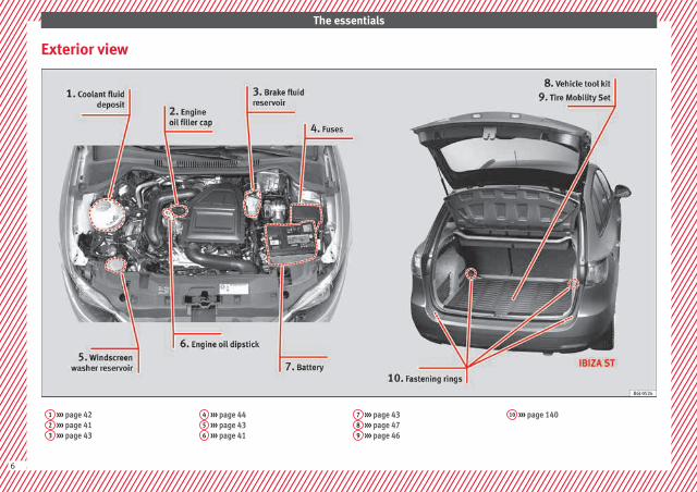
The essentials
Exterior view
1 ››› page 422 ››› page 413 ››› page 43
4 ››› page 445 ››› page 436 ››› page 41
7 ››› page 438 ››› page 479 ››› page 46
10 ››› page 140
6

The essentials
Interior view (left guide)
1 ››› page 132 ››› page 213 ››› page 224 ››› page 34
5 ››› page 356 ››› page 237 ››› page 258 ››› page 24
9 ››› page 3910 ››› page 2211 ››› page 1412 ››› page 20
13 ››› page 3714 ››› page 1115 ››› page 1016 ››› page 44
17 ››› page 1218 ››› page 1219 ››› page 13
7

The essentials
Interior view (right-hand drive)
1 ››› page 222 ››› page 343 ››› page 224 ››› page 39
5 ››› page 246 ››› page 237 ››› page 258 ››› page 35
9 ››› page 2110 ››› page 1311 ››› page 1012 ››› page 14
13 ››› page 1314 ››› page 3715 ››› page 1216 ››› page 12
17 ››› page 2018 ››› page 4419 ››› page 11
8

The essentials
How it works
Opening and closing
Doors
Fig. 1 Remote control key: buttons.
Fig. 2 See position on page 7-8
Locking and unlocking the vehicle using thekey
● Locking: press the ››› Fig. 1 button.
● Unlocking: press the ››› Fig. 1 button.
● Unlocking the rear lid: press the ››› Fig. 1 button until all the turn signals onthe vehicle briefly light up.
Locking and unlocking with the central lock-ing switch
● Locking: press the ››› Fig. 2 button. Noneof the doors can be opened from the outside.The doors can be opened from the inside bypulling the inside door handle.
● Unlocking: press the ››› Fig. 2 button.
››› in Description on page 112
››› page 112
Rear lid
Fig. 3 Rear lid: opening from the outside.
The rear lid opening system operates electri-cally. It is activated by using the handle onthe boot lid.
This system may or may not be operative, de-pending on the situation of the vehicle.
If the rear lid is locked then it cannot beopened, however if it is unlocked then theopening system is operative and the rear lidmay be opened.
To lock/unlock, press the button or button ››› Fig. 1 on the remote control key.
A warning appears on the instrument paneldisplay if the rear lid is open or not properlyclosed.* An audible warning is also given ifthe boot lid is opened while the vehicle ismoving faster than 6 km/h (4 mph)*. »
9

The essentials
● Opening the rear lid: Pull on the releaselever and lift it up ››› Fig. 3. The rear lid opensautomatically.
● Closing the rear lid: Hold it by one of thehandles on the interior lining and close it bypushing gently.
››› in Opening and closing onpage 120
››› page 10
Unlocking the rear lid manually
Fig. 4 IBIZA/IBIZA SC: Unlocking the rear lidmanually.
Fig. 5 IBIZA ST: Unlocking the rear lid man-ually.
This allows the vehicle to be opened if thecentral locking does not work (for example, ifthe battery is flat)
There is a groove in the luggage compart-ment allowing access to the emergencyopening mechanism.
Opening the rear lid from inside the luggagecompartment
● Insert the key in the groove and unlock thelocking system, turning the key from right toleft, as shown by the arrow ››› Fig. 4, ››› Fig. 5.
Bonnet
Fig. 6 See position on page 7-8
Fig. 7 Cam under the bonnet
● Opening the bonnet: Pull the lever underthe dashboard ››› Fig. 6 1 .
● Lifting up the bonnet: press the releasecatch under the bonnet upwards ››› Fig. 7 2 .The arrester hook under the bonnet is re-leased.
10

The essentials
● Release the bonnet stay and secure it inthe fixture designed for this in the bonnet.
››› in safety notes for work in the en-gine compartment on page 202
››› page 201
Electric windows*
Fig. 8 See position on page 7-8
● Opening the window: Press the button.
● Closing the window: Pull the button.
Buttons on the driver door
Window on the front left door
Window on the front right door
Safety switch for deactivating the electricwindow buttons on the rear doors (only 5-door vehicles)
1
2
3
Window on the rear left door (only 5-doorvehicles)
Window on the right rear door (only 5-door vehicles)
››› in Opening and closing of the elec-tric windows* on page 121
››› page 120
Panoramic roof*
Fig. 9 On the interior roof lining: Panoramicsunroof controls
● Opening: Press the ››› Fig. 9 A button onceonly. If you keep it pressed down, it will opento the desired position.
● Closing: Press the ››› Fig. 9 B button onceonly. If you keep it pressed down, it will closeto the desired position.
4
5
Restoring one-touch opening and closing
● Close the sunroof manually until it is com-pletely closed. Release the button.
● Press the closing button again, keeping itpressed down, until a complete opening andclosing cycle has taken place.
››› in Opening or closing of the tiltingpanoramic roof on page 122
››› page 122
››› page 11
Operation of the panoramic sunroof
Fig. 10 Emergency operation of the panoram-ic/tilting sunroof.
In case of a breakdown, the sunroof may beclosed manually. »
11

The essentials
● Remove the plastic cover by inserting ascrewdriver into the rear section.
● Insert an Allen key (4 mm) into the openingas far as possible and close the sunroof.
Before driving
Manually adjusting the front seats
Fig. 11 Front seats: manual seat adjustment.
Forward/back: pull the lever and movethe seat forwards or backwards.
Raising/lowering: pull/push the lever.
Tilting the backrest: turn the hand wheel.
1
2
3
Folding down the backrest (only 3-doorvehicles): pull the lever and push thebackrest forward.
››› in Adjusting the front seats onpage 132
Adjusting the head restraints
Fig. 12 Front seat: adjustment of the head re-straint.
● Grab the sides of the head restraints withboth hands and push upwards to the desiredposition. To lower it, repeat the same action,pressing the 1 button on the side.
››› in Adjusting or disassembling thehead restraints on page 134
››› page 60, ››› page 133
4 Adjustment of the seat belt
Fig. 13 Positioning and removing the seatbelt buckle.
12
The essentials
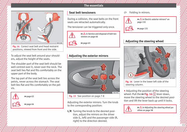
Fig. 14 Correct seat belt and head restraintpositions, viewed from front and the side.
To adjust the seat belt around your should-ers, adjust the height of the seats.
The shoulder part of the seat belt should bewell centred over it, never over the neck. Theseat belt lies flat and fits comfortably on theupper part of the body.
The lap part of the seat belt lies across thepelvis, never across the stomach. The seatbelt lies flat and fits comfortably on the pel-vis.
››› page 63
››› page 64
Seat belt tensioners
During a collision, the seat belts on the frontseats are retracted automatically.
The tensioner can be triggered only once.
››› in Service and disposal of belt ten-sioners on page 66
››› page 65
Adjusting the exterior mirrors
Fig. 15 See position on page 7-8
Adjusting the exterior mirrors: Turn the knobto the corresponding position:
Turning the knob to the desired posi-tion, adjust the mirrors on the driverside (L, left) and the passenger side (R,right) to the direction desired.
L/R
Folding in mirrors.
››› in Electric exterior mirrors* onpage 132
››› page 131
Adjusting the steering wheel
Fig. 16 Lever in the lower left side of thesteering column.
● Adjusting the position of the steeringwheel: Pull the ››› Fig. 16 1 lever down,move the steering wheel to the desired posi-tion and lift the lever back up until it locks.
››› in Adjusting the steering wheel po-sition on page 58
13

The essentials
Airbags
front airbags
Fig. 17 Driver airbag located in steeringwheel.
Fig. 18 Front passenger airbag located indash panel.
The front airbag for the driver is located inthe steering wheel ››› Fig. 17 and the airbagfor the front passenger is located in the dashpanel ››› Fig. 18. Airbags are identified by theword “AIRBAG”.
When the driver and front passenger airbagsare deployed, the covers remain attached tothe steering wheel and dashboard, respec-tively ››› Fig. 17 ››› Fig. 18.
In conjunction with the seat belts, the frontairbag system gives the driver and the frontpassenger additional protection for the head
and chest in the event of a severe frontal col-lision.
The special design of the airbag allows thecontrolled escape of the propellant gas whenan occupant puts pressure on the bag. Thus,the head and chest are surrounded and pro-tected by the airbag. After the collision, theairbag deflates sufficiently to allow visibility.
››› page 69
Deactivating the front passenger frontairbag
Fig. 19 Front passenger front airbag switch.
To deactivate the front passenger front air-bag:
● Open the glove compartment on the frontpassenger side.
14
The essentials
● Insert the key into the slot provided in thedeactivation switch.
● Approximately ¾ of the length of the keyremains inserted (the maximum).
● Turn the key, changing its position to .Do not force it. If you have difficulty, ensurethat you have inserted the key as far as it willgo.
● Finally, check the control lamp on the in-strument panel where it shows the following should appear .
››› in Deactivation of front passengerfront airbag* on page 71
››› page 70
Side airbags*
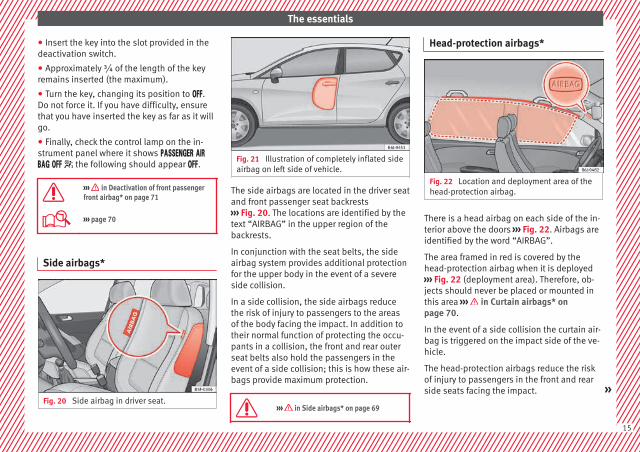
Fig. 20 Side airbag in driver seat.
Fig. 21 Illustration of completely inflated sideairbag on left side of vehicle.
The side airbags are located in the driver seatand front passenger seat backrests››› Fig. 20. The locations are identified by thetext “AIRBAG” in the upper region of thebackrests.
In conjunction with the seat belts, the sideairbag system provides additional protectionfor the upper body in the event of a severeside collision.
In a side collision, the side airbags reducethe risk of injury to passengers to the areasof the body facing the impact. In addition totheir normal function of protecting the occu-pants in a collision, the front and rear outerseat belts also hold the passengers in theevent of a side collision; this is how these air-bags provide maximum protection.
››› in Side airbags* on page 69
Head-protection airbags*
Fig. 22 Location and deployment area of thehead-protection airbag.
There is a head airbag on each side of the in-terior above the doors ››› Fig. 22. Airbags areidentified by the word “AIRBAG”.
The area framed in red is covered by thehead-protection airbag when it is deployed››› Fig. 22 (deployment area). Therefore, ob-jects should never be placed or mounted inthis area ››› in Curtain airbags* onpage 70.
In the event of a side collision the curtain air-bag is triggered on the impact side of the ve-hicle.
The head-protection airbags reduce the riskof injury to passengers in the front and rearside seats facing the impact. »
15
The essentials
››› in Curtain airbags* on page 70
Child seats
Important information regarding thefront passenger's airbag
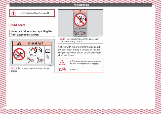
Fig. 23 Passenger's side sun visor: airbagsticker.
Fig. 24 On the rear frame of the passengerside door: airbag sticker.
A sticker with important information aboutthe passenger airbag is located on the pas-senger's sun visor and/or on the passengerside door frame.
››› in Important information regardingthe front passenger's airbag on page 72
››› page 72
16

The essentials
Ways to secure a child seat
Fig. 25 On the rear seats: Possible installationsfor the child seat.
Figure ››› Fig. 25 A shows the basic child re-straint system mounting using lower retain-ing rings and the upper retaining strap. Fig-ure ››› Fig. 25 B shows the child restraintsystem mounting using the vehicle seat belt.
You can secure a child seat to the rear seat orfront passenger seat in the following ways:
● Child seats in groups 0 to 3 can be securedwith a seat belt.
● Child seats for groups 0, 0+ and 1 can befastened without seatbelts, using the “ISO-FIX” system, using the “ISOFIX” ››› page 18securing rings.
● During installation of some models ofgroup I, II and III child seats in the rear seat,difficulty may arise in mounting given thatthe seat comes into contact with the head re-
straint. In this case, adjust the height of thehead restraint or remove it from the seat fol-lowing the instructions in the correspondingchapter ››› page 133. Once you removethe child seat, replace the head restraint inits original position.
Weightgroup
Seating position
Frontpassen-ger seat
Rear sideseat
Rear cen-tral seat
Group 0to 10 kg
U* U U
Group 0+to 13 kg
U* U U
Group I9 to 18 kg
U* U U
Group II15 to 25 kg
U* U U
Group III22 to 36 kg
U* U U »
17
The essentials
Suitable for universal restraint systemsfor use in this weight group.
Move the front passenger seat as farback as possible, as high as possibleand always disable the airbag.
U:
*:
The systems include the child restraint sys-tem mounting with an upper retaining strap(Top Tether) and lower anchoring points onthe seat.
››› in Safety instructions on page 73
“ISOFIX” and Top Tether child seat mounting system*
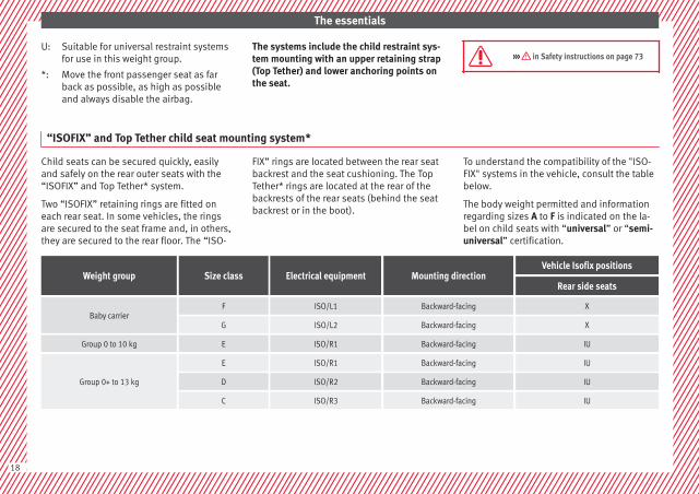
Child seats can be secured quickly, easilyand safely on the rear outer seats with the“ISOFIX” and Top Tether* system.
Two “ISOFIX” retaining rings are fitted oneach rear seat. In some vehicles, the ringsare secured to the seat frame and, in others,they are secured to the rear floor. The “ISO-
FIX” rings are located between the rear seatbackrest and the seat cushioning. The TopTether* rings are located at the rear of thebackrests of the rear seats (behind the seatbackrest or in the boot).
To understand the compatibility of the "ISO-FIX" systems in the vehicle, consult the tablebelow.
The body weight permitted and informationregarding sizes A to F is indicated on the la-bel on child seats with “universal” or “semi-universal” certification.
Weight group Size class Electrical equipment Mounting directionVehicle Isofix positions
Rear side seats
Baby carrierF ISO/L1 Backward-facing X
G ISO/L2 Backward-facing X
Group 0 to 10 kg E ISO/R1 Backward-facing IU
Group 0+ to 13 kg
E ISO/R1 Backward-facing IU
D ISO/R2 Backward-facing IU
C ISO/R3 Backward-facing IU
18

The essentials
Weight group Size class Electrical equipment Mounting directionVehicle Isofix positions
Rear side seats
Group I 9 to 18 kg
D ISO/R2 Backward-facing IU
C ISO/R3 Backward-facing IU
B ISO/F2 Forward-facing IU
B1 ISO/F2X Forward-facing IU
A ISO/F3 Forward-facing IU
Group II 15 to 25 kg --- --- Forward-facing ---
Group III 22 to 36 kg --- --- Forward-facing ---
Suitable for ISOFIX universal child re-straint systems approved for use in thisweight group.
ISOFIX position not suitable for ISOFIXchild restraint systems for this weightgroup or size class.
››› in Safety instructions on page 73
IU:
X:
Mount the child seat with the “ISOFIXsystems”
Fig. 26 ISOFIX securing rings.
When removing or fitting the child seat,please be sure to follow the manufacturer'sinstructions.
● Press the child seat onto the “ISOFIX” re-taining rings until the child seat can be heardto engage securely. If the child seat is fittedwith any other anti-rotation system, followthe manufacturer instructions carefully.
● Pull on both sides of the child seat to en-sure that it is secure.
Child seats with the “ISOFIX” and Top Tether*attachment system are available from Techni-cal Services.
19

The essentials
Top Tether* retainer straps
Fig. 27 Position of the Top Tether rings on theback of the rear seat.
Child seats with the Top Tether system comewith a strap for securing the seat to the vehi-cle anchor point, located at the back of therear seat backrest and provide greater re-straint.
The objective of this strap is to reduce theforward movement of the child seat in acrash, to reduce the risk of injuries to thehead from hitting the inside of the vehicle.
Using the Top Tether in rear-facing mountedseats
Currently, there are very few rear-facing childsafety seats that have Top Tether. Pleasecarefully read and follow the seat manufac-turer instructions to learn the proper way toinstall the Top Tether strap.
Securing the Top Tether* of the childseat to the anchorage point
Fig. 28 Retainer strap: correct adjustmentand fitting.
Securing to the anchorage point located onthe rear of the backrest
● Follow the manufacturer's instructions todeploy the child seat Top Tether retainerstrap.
● Guide the strap under the rear seat head re-straint ››› Fig. 28 (lift the head restraint wherenecessary).
● Slide the strap and secure it properly withthe anchorage of the backrest.
● Firmly tighten the Top Tether belt followingthe manufacturer's instructions.
Releasing the retaining strap
● Loosen the strap following the manufactur-er's instructions.
● Push the lock and release it from the an-choring support.
››› in Safety instructions on page 73
Starting the vehicle
Ignition lock
Fig. 29 See position on page 7-8
Switch ignition on: Place the key in the igni-tion and start the engine.
Locking and unlocking the steering wheel
● Engaging the steering wheel lock: Removethe key from the ignition and turn the wheeluntil it locks. In vehicles with an automaticgearbox, the gear lever must be in the P posi-tion in order to remove the key. If necessary,
20

The essentials
press the locking key on the selector leverand release it again.
● Unlocking the steering wheel: Put the keyinto the ignition and turn it at the same timeas the steering wheel in the direction indica-ted by the arrow. If it is not possible to turnthe steering wheel, it may be because it islocked.
Turning on/switching off the ignition, glowplugs reheating
● Switch ignition on: Turn the key to the 2
position.
● Switch ignition off. Turn the key to the 1
position.
● Diesel vehicles : The glow plugs reheatwhen the ignition is switched on
Starting the engine
● Manual gearbox: press the clutch pedal allthe way down and move the gearbox lever in-to neutral.
● Automatic gearbox: Press the brake pedaland move the selector lever to the P positionor into N.
● Turn the key to the 3 position. The key au-tomatically returns to the 2 position. Do notpress the accelerator.
Start-Stop System*
When you stop and release the clutch pedal,the Start-Stop system* turns off the engine.The ignition remains switched on.
››› in Ignition key positions onpage 154
››› page 153
Lights and visibility
Headlight switch
Fig. 30 See position on page 7-8
● Turn the switch to the required position››› Fig. 30.
Sym-bol
Ignition switch-ed off
Ignition is switch-ed on
Fog lights, dippedbeam and sidelights off.
Light off or daytimedriving light on.
The “Coming home”and “Leavinghome” guide lightsmay be switchedon.
Automatic control ofdipped beam and day-time driving light.
Side light on.
Dipped beam head-light off
Dipped beam switch-ed on.
Front fog lights: move the switch to thefirst position, from positions , or .
Rear fog light: move the switch completelyfrom positions , or .
Switching off fog lights: Push the switch orturn it to the position.
››› in Switching lights on and off onpage 123
››› page 123
21

The essentials
Turn signal and main beam lever
Fig. 31 See position on page 7-8
More the lever to the required position:
Right turn signal: Right-hand parkinglight (ignition switched off).
Left turn signal: Left-hand parking light(ignition switched off).
Main beam switched on: Control lamp lit up on the instrument panel.
Headlight flasher: lit up when the lever ispushed. Control lamp lit up.
Lever all the way down to switch it off.
››› in Turn signal and main beam leveron page 125
››› page 125
1
2
3
4
Hazard warning lights
Fig. 32 See position on page 7-8
Switched on, for example:
● When approaching a traffic jam
● In an emergency
● The vehicle has broken down
● When towing or being towed
››› in Hazard warning lights onpage 128
››› page 127
Interior lights
Fig. 33 Detail of headliner: front interior light-ing.
Knob Function
Switches interior lights off.
Switches interior lights on.
Switches door contact control on (central po-sition).The interior lights come on automaticallywhen the vehicle is unlocked, a door isopened or the key is removed from the igni-tion.The lights go off a few seconds after all thedoors are closed, the vehicle is locked or theignition is switched on.
Turning the reading light on and off
››› page 128
22

The essentials
Windscreen wipers and window wiperblade
Fig. 34 Operating the windscreen wiper andrear wiper
More the lever to the required position:
0 Windscreen wiper off.
More the lever to the required position:
1
Windscreen wipers interval wipe.Using the control ››› Fig. 34 A adjust theinterval (vehicles without rain sensor), orthe sensitivity of the rain sensor.
2 Slow wipe.
3 Continuous wipe.
4 Short wipe. Brief press, short clean. Holdthe lever down for more time to increasethe wipe frequency.
5
Automatic wipe. The windscreen washerfunction is activated by pushing the leverforwards, and simultaneously the wind-screen wipers start.
More the lever to the required position:
6 Interval wipe for rear window. The wiperwill wipe the window approximately everysix seconds.
7 The rear window wash function is activa-ted by pressing the lever, and the rear wip-er starts simultaneously.
››› in Windscreen wipers on page 129
››› page 129
››› page 54
23

The essentials
Easy Connect
CAR menu settings (Setup)
Fig. 35 See position on page 7-8 Fig. 36 See position on page 7-8
To select the settings menus, press the EasyConnect button and the Setup functionbutton.
The actual number of menus available andthe name of the various options will dependon the vehicle’s electronics and equipment.
● Switch the ignition on.
● If the Infotainment System is off, switch iton.
● Press the system's MENU button and thenthe system's ››› Fig. 35 button or but-ton to go to the CAR menu ››› Fig. 36.
● Press the function button Setup to open themenu Vehicle settings ››› Fig. 36.
● To select a function in the menu, press thedesired button.
When you press the menu button, the last se-lected menu will always be displayed.
When the function button check box is activa-ted , the function is active.
Any changes made using the settings menusare automatically saved on closing theBACK menus.
Menu Submenu Possible setting Description
ESC system – Activation of the Electronic Stability Programme (ESC) ››› page 170
TyresTyre pressure monitoring Tyre pressure storing (Calibration) ››› page 104
Winter tyres Activation and deactivation of the speed warning. Setting the speed warning value ››› page 215
24

The essentials
Menu Submenu Possible setting Description
Driver assistance Tiredness detection Activation/deactivation ››› page 175
Parking and ma-noeuvring ParkPilot Automatically activate, front volume, front sound settings, rear volume, rear sound settings,
adjust volume››› page 176
Vehicle lightsVehicle interior lighting Instrument and switch lighting, footrest lighting ››› page 128
Coming home/Leaving homefunction Start time for “Coming home” function, start time for “Leaving home” function ››› page 126
Windscreen wipers Windscreen wipers Automatic windscreen wipers, wipe when reversing ››› page 23
Opening and clos-ing
Radio-operated remote control Convenience open function ››› page 122
Central locking system Unlocking doors, automatic locking/unlocking, audible confirmation ››› page 112
Multifunctiondisplay –
Current consumption, average consumption, volume to fill up, convenience equipment,ECOAdvice, journey duration, distance travelled, digital speed display, average speed,speeding warning, oil temperature, coolant temperature, restore data “from start”, restoredata “total calculation”
››› page 25
Date and time –Time source, set the time, automatic summer time setting, select time zone, time format, setthe date, date format
–
Measurement units – Distance, speed, temperature, volume, consumption –
Service – Chassis number, date of next SEAT service inspection, date of next oil change service ››› page 33
Factory settings –All settings can be reset: driver assistance, parking and manoeuvring, lights, rear view mir-rors, opening and closing, multi-function display
–
››› in CAR menu (Setup) on page 107
››› page 107
Driver information system
Introduction
With the ignition switched on, it is possibleto read the different functions of the displayby scrolling through the menus.
In vehicles with multifunction steering wheel,the multifunction display can only be operat-ed with the steering wheel buttons.
The number of menus displayed on the in-strument panel will vary according to the ve-hicle electronics and equipment. »
25

The essentials
A specialised workshop will be able to pro-gramme or modify additional functions, ac-cording to the vehicle equipment. SEAT rec-ommends visiting a SEAT Official Service.
Some menu options can only be read whenthe vehicle is at a standstill.
As long as a priority 1 warning is displayed, itwill not be possible to read the menus. Somewarning messages can be confirmed andmade to disappear with the windscreen wiperlever button or the multifunction steeringwheel button.
The information system also provides the fol-lowing information and displays (dependingon the vehicle's equipment):
Driving data ››› page 29■ Vehicle status■ MFD from departure■ MFD from refuelling■ MFD total calculation
Assist systems ››› table on page 27■ Reverse (optional)
Navigation ››› Booklet Navigation system
Audio ››› Booklet Radio or ››› Booklet Naviga-tion system
Telephone ››› Booklet Radio or ››› Book-let Navigation system
Vehicle ››› table on page 27
WARNING
Any distraction may lead to an accident, withthe risk of injury.
● Do not operate the instrument panel con-trols when driving.
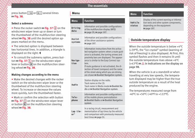
Operating the instrument panel me-nus
Fig. 37 Windscreen wiper lever: control but-tons.
Fig. 38 Right side of multifunction steeringwheel: control buttons.
The driver information system is controlledwith the multifunction steering wheel buttons››› Fig. 38 or with the windscreen wiper lever››› Fig. 37 (if the vehicle is not equipped withmultifunction steering wheel).
Enabling the main menu
● Switch the ignition on.
● If a message or vehicle pictogram appears,press button ››› Fig. 37 1 on the windscreenwiper lever or button on the multifunctionsteering wheel ››› Fig. 38.
● If managed from the windscreen wiper lev-er: to display the main screen ››› page 27 orto return to the main menu from anothermenu hold down the rocker button ››› Fig. 37
2 .
● If managed from the multifunction steeringwheel: the main menu list is not displayed.To go from point to point in the main menu,
26
The essentials
press button or several times››› Fig. 38.
Select a submenu
● Press the rocker switch ››› Fig. 37 2 on thewindscreen wiper lever up or down or turnthe thumbwheel of the multifunction steeringwheel ››› Fig. 38 until the desired option ap-pears marked on the menu.
● The selected option is displayed betweentwo horizontal lines. In addition, a triangle isdisplayed on the right:
● To consult the submenu option, press but-ton ››› Fig. 37 1 on the windscreen wiperlever or button on the multifunction steer-ing wheel ››› Fig. 38.
Making changes according to the menu
● Make the desired changes with the rockerswitch on the windscreen wiper lever or thethumbwheel of the multifunction steeringwheel. To increase or decrease the valuesmore quickly, turn the thumbwheel faster.
● Mark or confirm the selection with button››› Fig. 37 1 on the windscreen wiper leveror button on the multifunction steeringwheel ››› Fig. 38.
Menu
Menu Function
Drivingdata
Information and possible configurationsof the multifunction display (MFD)››› page 29, ››› page 107.
Assistsystems
Information and possible configurationsof the driver assistance systems››› page 107.
Naviga-tion
Information instructions from the activa-ted navigation system: when a route guid-ance is activated, the turning arrows andproximity bars are displayed. The appear-ance is similar to the Easy Connect sys-tem.If route guidance is not activated, the di-rection of travel (compass) and the nameof the street along which you are drivingare shown ››› Booklet Navigation system.
AudioStation display on the radio.Track name on the CD.Track name in Media mode ››› Booklet Ra-dio or ››› Booklet Navigation system.
Tele-phone
Information and possible configurationsof the mobile phone preinstallation››› Booklet Radio or ››› Booklet Navigationsystem.
Lap tim-er*
In a racing circuit, measurement andmemorisation of lap times by the vehicleand comparison with previously measuredbest times ››› page 31.
Menu Function
Vehiclestatus
Display of the current warning or informa-tion texts and other system components,depending on the equipment››› page 107.
Outside temperature display
When the outside temperature is below +4°C(+39°F), the “ice crystal” symbol (warning ofrisk of freezing) is also displayed. At first, thissymbol flashes and then it remains lit untilthe outside temperature rises above +6°C(+43°F) ››› in Indications on the display onpage 98.
When the vehicle is at a standstill or whentravelling at very low speeds, the tempera-ture displayed may be higher than the trueoutside temperature as a result of the heatproduced by the engine.
The temperatures measured range from-40°C to +50°C (-40°F to +122°F).
27

The essentials
Gear-change indicator
Fig. 39 Instrument panel: gear-change indica-tor (manual gearbox).
A gear change will be recommended if thegear you are in is not the most economicalchoice. If no gear-change is recommended, itmeans that you are already in the most eco-nomical gear.
Vehicles with a manual gearbox
The following display symbols ››› Fig. 39mean:
● Change to a higher gear: the suggestedgear appears to the right of the current gearwhen a higher gear is recommended.
● Change to a lower gear: the suggestedgear appears to the left of the current gearwhen a lower gear is recommended.
The gear recommendation may occasionallyskip a gear (2nd 4th).
Vehicles with an automatic gearbox*
The display is only visible in tiptronic mode››› page 162.
The following display symbols mean:
● Shifting up a gear
● Shifting down a gear
CAUTION
The gear-change indicator is intended to helpsave fuel, but it is not intended to recom-mend the right gear for all driving situations.In certain situations, only the driver canchoose the correct gear (for instance whenovertaking, driving up a steep gradient ortowing a trailer).
Note
The display disappears from the instrumentpanel when you press the clutch pedal.
Bonnet, rear lid and doors open
Fig. 40 A: bonnet open; B: rear lid open; C:front left door open; D: rear right door open(5-door vehicles only).
When the ignition is switched on or whendriving, the bonnet, rear lid or doors that areopen will be indicated on the instrument pan-el display, and, as applicable, this will be in-dicated audibly. The display may vary accord-ing to the type of instrument panel fitted.
28

The essentials
Illustra-tion
Key to ››› Fig. 40
A Do not continue driving!The bonnet is open or is not properlyclosed ››› page 201.
B Do not continue driving!The rear lid is open or is not properlyclosed ››› page 9.
C, D Do not continue driving!A vehicle door is open or is not properlyclosed ››› page 112.
Warning and information messages
The system runs a check on certain compo-nents and functions when the ignition isswitched on and while the vehicle is moving.Faults in the operation are displayed on thescreen using red and yellow symbols andmessages on the instrument panel display(››› page 100, ››› page 35) and, insome cases, with audible warnings. The dis-play may vary according to the type of instru-ment panel fitted.
Priority 1 warning (red symbols)
Symbol flashing or lit; partly combined with audiblewarnings. Stop the vehicle! It is dangerous ››› in Warningsymbols on page 101!Check the function that is faulty and repair it. If necessa-ry, request assistance from specialised personnel.
Priority 2 warning (yellow symbols)
Symbol flashing or lit; partly combined with audiblewarnings.A faulty function, or fluids which are below the correctlevels may cause damage to the vehicle! ››› in Warn-ing symbols on page 101Check the faulty function as soon as possible. If neces-sary, request assistance from specialised personnel.
Informative text
Information relating to different vehicle processes.
Assist systems submenu
Assistsystemsmenu
Function
Tirednessdetection*
Switching the tiredness detection onor off (pause recommendation)››› page 175.
Journey data
Memory
The MFD (multifunction display) shows differ-ent values for the journey and the consump-tion.
Changing between display modes on theMFD
● In vehicles without multifunction steeringwheel: Press the rocker switch on thewindscreen wiper lever ››› Fig. 37.
● Vehicles with a multifunction steeringwheel: turn the thumbwheel ››› Fig. 38.
Multifunction display memory
The multifunction display is equipped withthree memories that work automatically: MFDfrom departure, MFD from refuelling and MFDtotal calculation. On the screen display, youcan read which memory is currently dis-played.
Toggle between memories with the ignitionon and the memory displayed
Press the button on the windscreenwiper lever or the button of the multifunc-tion steering wheel. »
29
The essentials
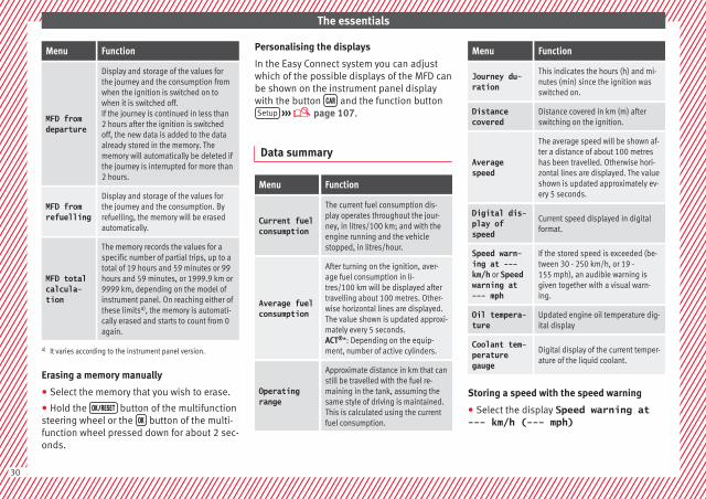
Menu Function
MFD fromdeparture
Display and storage of the values forthe journey and the consumption fromwhen the ignition is switched on towhen it is switched off.If the journey is continued in less than2 hours after the ignition is switchedoff, the new data is added to the dataalready stored in the memory. Thememory will automatically be deleted ifthe journey is interrupted for more than2 hours.
MFD fromrefuelling
Display and storage of the values forthe journey and the consumption. Byrefuelling, the memory will be erasedautomatically.
MFD totalcalcula-tion
The memory records the values for aspecific number of partial trips, up to atotal of 19 hours and 59 minutes or 99hours and 59 minutes, or 1999.9 km or9999 km, depending on the model ofinstrument panel. On reaching either ofthese limitsa), the memory is automati-cally erased and starts to count from 0again.
a) It varies according to the instrument panel version.
Erasing a memory manually
● Select the memory that you wish to erase.
● Hold the button of the multifunctionsteering wheel or the button of the multi-function wheel pressed down for about 2 sec-onds.
Personalising the displays
In the Easy Connect system you can adjustwhich of the possible displays of the MFD canbe shown on the instrument panel displaywith the button and the function buttonSetup ››› page 107.
Data summary
Menu Function
Current fuelconsumption
The current fuel consumption dis-play operates throughout the jour-ney, in litres/100 km; and with theengine running and the vehiclestopped, in litres/hour.
Average fuelconsumption
After turning on the ignition, aver-age fuel consumption in li-tres/100 km will be displayed aftertravelling about 100 metres. Other-wise horizontal lines are displayed.The value shown is updated approxi-mately every 5 seconds.ACT®*: Depending on the equip-ment, number of active cylinders.
Operatingrange
Approximate distance in km that canstill be travelled with the fuel re-maining in the tank, assuming thesame style of driving is maintained.This is calculated using the currentfuel consumption.
Menu Function
Journey du-ration
This indicates the hours (h) and mi-nutes (min) since the ignition wasswitched on.
Distancecovered
Distance covered in km (m) afterswitching on the ignition.
Averagespeed
The average speed will be shown af-ter a distance of about 100 metreshas been travelled. Otherwise hori-zontal lines are displayed. The valueshown is updated approximately ev-ery 5 seconds.
Digital dis-play ofspeed
Current speed displayed in digitalformat.
Speed warn-ing at ---km/h or Speedwarning at--- mph
If the stored speed is exceeded (be-tween 30 - 250 km/h, or 19 -155 mph), an audible warning isgiven together with a visual warn-ing.
Oil tempera-ture
Updated engine oil temperature dig-ital display
Coolant tem-peraturegauge
Digital display of the current temper-ature of the liquid coolant.
Storing a speed with the speed warning
● Select the display Speed warning at--- km/h (--- mph)
30
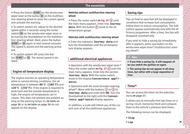
The essentials
● Press the button on the windscreenwiper lever or the button on the multifunc-tion steering wheel to store the current speedand activate the warning.
● To switch system on: adjust to the desiredspeed within 5 seconds using the rockerswitch on the windscreen wiper lever orby turning the thumbwheel on the multifunc-tion steering wheel. Next, press the button or again or wait several seconds.
The speed is stored and the warning activa-ted.
● To switch system off: press the but-ton or . The stored speed is de-leted.
Engine oil temperature display
The engine reaches its operating temperaturewhen in normal driving conditions, the oiltemperature is between 80°C (180°F) and120°C (250°F). If the engine is required towork hard and the outside temperature ishigh, the engine oil temperature can in-crease. This does not present any problem aslong as the warning lamps ››› table onpage 36 or ››› table on page 36 do notappear on the display.
Vehicles without multifunction steeringwheel
● Press the rocker switch ››› Fig. 37 2 untilthe main menu appears. Enter into Journeydata. With the button 2 move to the oiltemperature gauge.
Vehicles with multifunction steering wheel
● Enter the submenu Journey data andturn the thumbwheel until the oil tempera-ture display appears.
additional electrical appliances
● Operation with the windscreen wiper lever*:Press the rocker switch ››› Fig. 37 2 until themain menu appears. Enter into the sectionJourney data. With the rocker switch,move to the display Convenience appli-ances.
● Operation with the multi-function steeringwheel*: Move with the buttons 1 or 2 toJourney data and enter with OK. Turn thethumbwheel to the right until the Conven-ience appliances display appears.
In addition, a scale will inform you of the cur-rent sum of all the additional appliances.
Saving tips
Tips on how to save fuel will be displayed inconditions that increase fuel consumption.Follow them to reduce consumption. The indi-cations appear automatically only with the ef-ficiency programme. After a time, the tips willdisappear automatically.
If you wish to hide a saving tip immediatelyafter it appears, press any button on thewindscreen wiper lever*/multifunction steer-ing wheel*.
Note
● If you hide a saving tip, it will reappear af-ter you switch the ignition on again.
● The saving tips do not appear in all situa-tions, but rather with a large separation oftime.
Timer*
You can access the timer via the selectionmenu ››› page 27.
It allows you to manually time lap times on aracing circuit, memorise them and comparethem to the vehicle's previous best times.
The following menus can be displayed:
● Stop● Lap »
31

The essentials
● Pause● Partial time● Statistics
Change from one menu to another
● Vehicles without multifunction steeringwheel: press the rocker switch in thewindscreen wiper lever.
● Vehicles with multifunction steering wheel:press or .
Menu “Stop”
Start
The timer starts.If there are existing laps and they are in-cluded in the statistics, it will begin withthe number of laps in question.It is only possible to begin with a new firstlap if the statistics have been reset first inthe Statistics menu.
Sincestart
The timer begins when the vehicle setsoff.If the vehicle is already moving, the timerbegins once the vehicle has stopped.
Statis-tics
The Statistics menu is displayed onthe screen.
Menu “Lap”
New lapThe timer of the current lap stops and anew lap starts immediately. The time forthe lap you have just completed is inclu-ded in the statistics.
Menu “Lap”
Partialtime
For about 5 seconds a partial time is dis-played. The timer continues in parallel.
StopThe current lap timer will be interrupted.The lap does not end. The Pause menu isdisplayed.
Menu “Pause”
Continue The interrupted timer continues.
New lap A new timer starts. The halted lap endsand is included in the statistics.
Interr.lap
The timer of the current lap ends and iscancelled. It is not included in the statis-tics.
End The current timer ends. The lap is inclu-ded in the statistics.
Menu “Partial time”
Partialtime
For about 5 seconds a partial time is dis-played. The timer continues in parallel.
New lapThe timer of the current lap stops and anew lap starts immediately. The time forthe lap you have just completed is inclu-ded in the statistics.
StopThe current lap timer will be interrupted.The lap does not end. The Pause menu isdisplayed.
Menu “Statistics”
View of the latest lap times:– total time– best lap time– worst lap time– average lap durationA maximum of 10 laps is possible, and atotal duration of 99 hours, 59 minutesand 59 seconds.If one of the 2 limits is reached, you willhave to reset the statistics in order to be-gin a new timer.
Back This returns to the previous menu.
Reset-ting tozero
All the memorised statistical data are re-set.
WARNING
Do your best to avoid handling the timerwhile driving.
● Only set the timer or consult statisticswhen the vehicle is stationary.
● While driving, do not handle the timer incomplicated driving situations.
Speed warning device
The speed warning device warns the driverwhen they have exceeded the pre-set speedlimit by 3 km/h. An audible warning is givenand the lamp can be seen simultaneously
32

The essentials
on the instrument panel, as well as a mes-sage for the driver: speed warning ex-ceeded! The warning lamp switches offwhen reducing speed below the stored maxi-mum limit.
Speed warning programming is recommen-ded if you wish to be reminded of a maxi-mum speed, such as when travelling in acountry with different speed limits or for amaximum speed for winter tyres.
Setting speed limit warning
You can use the radio or the Easy Connect* toset, alter or cancel the speed limit warning.
● Vehicles with radio: press the button SETUP
> control button Driver Assistant >Speed warning.
● Vehicles with Easy Connect: press the but-ton Systems or else Vehicle systems >Driver assistant > Speed warning.
The warning limit can be set from 30 to240 km/h (20 to 150 mph). The adjustmentis done in 10 km/h (mph) intervals.
Note
● Please bear in mind that, even with thespeed warning function, it is still importantto keep an eye on the vehicle speed with thespeedometer and to observe the legal speedlimits.
● The speed limit warning function in the ver-sion for several countries warns you at aspeed of 120 km/h (80 mph). This is a facto-ry-set speed limit.
Service intervals
The service interval indication appears on theinstrument panel display ››› Fig. 121 4 .
SEAT distinguishes between services with en-gine oil change (e.g. Oil change service) andservices without engine oil change (e.g. In-spection).
In vehicles with Services established by timeor mileage, the service intervals are alreadypre-defined.
In vehicles with LongLife Service, the inter-vals are determined individually. Thanks totechnological progress, maintenance workhas been greatly reduced. Because of thetechnology used by SEAT, with this serviceyou only need to change the oil when the ve-hicle so requires. To calculate this change(max. 2 years), the vehicle's conditions ofuse and individual driving styles are consid-ered. The pre-warning first appears 20 daysbefore the date established for the corre-sponding service. The kilometres (miles) re-maining until the next service are alwaysrounded up to the nearest 100 km (miles)and the time is given in complete days. Thecurrent service message cannot be viewed
until 500 km after the last service. Prior tothis, only lines are visible on the display.
Inspection reminder
When the Service date is approaching, whenthe ignition is switched on a Service remind-er is displayed.
Vehicles without text messages: a span-ner will be displayed on the instrumentpanel plus an indication in km.
The kilometres indicated are the maximumnumber of kilometres that can be travelleduntil the next service. After a few seconds,the display mode changes. A clock symbolappears and the number of days until thenext service is due.
Vehicles with text messages: Service in--- km or --- days will be shown on theinstrument panel display.
Service due
When the service date is due, an audiblewarning is given when the ignition is switch-ed on and the spanner displayed on thescreen flashes for a few seconds.
Vehicles with text messages: Service nowwill be shown on the instrument panel dis-play. »
33

The essentials
Reading a service notification
With the ignition switched on, the engine offand the vehicle at a standstill, the currentservice notification can be read:
Press and hold the button 4 for more than 5seconds to consult the service message.
When the service date has passed, a minussign is displayed in front of the number of kil-ometres or days.
Vehicles with text messages: the followingmessage is displayed: Service --- km(miles) or --- days ago.
The time can also be set via the key andSetup function button in the Easy Connect
system ››› page 107.
Resetting service interval display
If the service was not carried out by a SEATdealership, the display can be reset as fol-lows:
● Switch off the ignition, press and hold but-ton ››› Fig. 121 4 .
● Switch ignition back on.
● Release THE 4 ››› Fig. 121 button andpress it again for the next 20 seconds.
Note
● The service message disappears after a fewseconds, when the engine is started or when
OK/RESET is pressed on the windscreen wiperlever, or OK on the multifunction steeringwheel.
● In vehicles with the LongLife system inwhich the battery has been disconnected fora long period of time, it is not possible to cal-culate the date of the next service. Thereforethe service interval display may not be cor-rect. In this case, bear in mind the maximumservice intervals permitted in the ››› Book-let Maintenance Programme.
Cruise control
Operating the cruise control system(CCS)*
Fig. 41 See position on page 7-8
● Switching on the CCS: Move switch››› Fig. 41 1 to . The system is on. If no
speed has been programmed, the system willnot control it.
● Activating the CCS: Press button ››› Fig. 412 in the area. The current speed is
memorised and controlled.
● Temporarily switching off the CCS: Moveswitch ››› Fig. 41 1 to or push thebrake. The cruise control system is switchedoff temporarily.
● Reactivating the CCS: Press button››› Fig. 41 2 in . The memorised speedis saved and controlled again.
● Increasing stored speed during CCS regula-tion: press button 2 in . The vehicle ac-celerates until the new stored speed.
● Reducing stored speed during CCS regula-tion: press button 2 in to lower thespeed by 1 km/h (1 mph). Speed is reduceduntil reaching the new stored speed.
● Switching off the CCS: Move switch››› Fig. 41 1 to . The system is disconnec-ted and the memorised speed is deleted.
››› in Operation on page 184
››› page 184
34

The essentials
Warning lamps
On the instrument panel
Fig. 42 See position on page 7-8
Red warning lamps
Central warning lamp: additionalinformation on the instrument pan-el display
–
Parking brake on. ››› page 156››› page 104
Do not continue driving!The brake fluid level is too low orthere is a fault in the brake system.
Lit up or flashing: Do not continue driving!Fault in the steering.
››› page 105
Driver or passenger has not fas-tened seat belt.
››› page 62
Use the foot brake!
Yellow warning lamps
Central warning lamp: additionalinformation on the instrument pan-el display
– »
35

The essentials
Front brake pads worn.
››› page 169
it lights up: Fault in the ESC, or dis-connection caused by the system.
flashes: ESC or ASR activated.
ASR manually deactivated.Or else: ESC in Sport mode.
ABS faulty or does not work.
Rear fog light switched on.››› page 21
lights up or flashes: fault in theemission control system.
››› page 106
it lights up: pre-ignition of dieselengine. ››› page
101flashes: fault in the diesel enginemanagement.
fault in the petrol engine manage-ment.
››› page 101
lights up or flashes: fault in thesteering system.
››› page 105
Tyre pressure too low, or fault inthe tyre pressure monitoring sys-tem.
››› page 104
Fuel tank almost empty.››› page 105
Fault in airbag system and seatbelt tensioners.
››› page 66
Other warning lamps
Left or right turn signal.
››› page 22
Hazard warning lights on.››› page 127
Trailer turn signals››› page 187
it lights up: Press the foot brake!flashes: the selector lever lockingbutton has not engaged.
››› page 159
it lights up: cruise control activatedor speed limiter switched on andactive. ››› page
34flashes: the speed set by thespeed limiter has been exceeded.
Main beam on or flasher on.››› page 22
On the instrument panel display
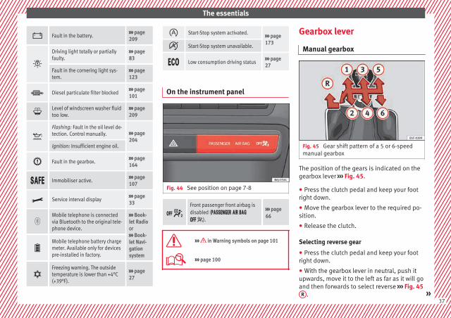
Fig. 43 See position on page 7-8
Do not continue driving!With the corresponding indica-tion: door(s), rear lid or bonnetopen or not properly closed.
››› page 112››› page 9››› page 201
Ignition: Do not carry on driv-ing! Engine coolant level too low,coolant temperature too high ››› page
207Flashing: Fault in the enginecoolant system.
Do not continue driving!Engine oil pressure too low.
››› page 204
36
The essentials
Fault in the battery.››› page 209
Driving light totally or partiallyfaulty.
››› page 83
Fault in the cornering light sys-tem.
››› page 123
Diesel particulate filter blocked››› page 101
Level of windscreen washer fluidtoo low.
››› page 209
Flashing: Fault in the oil level de-tection. Control manually. ››› page
204Ignition: Insufficient engine oil.
Fault in the gearbox.››› page 164
Immobiliser active.››› page 107
Service interval display››› page 33
Mobile telephone is connectedvia Bluetooth to the original tele-phone device.
››› Book-let Radioor››› Book-let Navi-gationsystem
Mobile telephone battery chargemeter. Available only for devicespre-installed in factory.
Freezing warning. The outsidetemperature is lower than +4°C(+39°F).
››› page 27
Start-Stop system activated. ››› page 173
Start-Stop system unavailable.
Low consumption driving status››› page 27
On the instrument panel
Fig. 44 See position on page 7-8
Front passenger front airbag isdisabled ( ).
››› page 66
››› in Warning symbols on page 101
››› page 100
Gearbox lever
Manual gearbox
Fig. 45 Gear shift pattern of a 5 or 6-speedmanual gearbox
The position of the gears is indicated on thegearbox lever ››› Fig. 45.
● Press the clutch pedal and keep your footright down.
● Move the gearbox lever to the required po-sition.
● Release the clutch.
Selecting reverse gear
● Press the clutch pedal and keep your footright down.
● With the gearbox lever in neutral, push itupwards, move it to the left as far as it will goand then forwards to select reverse ››› Fig. 45R . »
37

The essentials
● Release the clutch.
››› in Driving with manual gearbox onpage 159
››› page 159
Automatic gearbox*
Fig. 46 Automatic gearbox: selector lever po-sitions.
Parking lock
Reverse gear
P
R
Neutral (idling)
Drive (forward)
Sport programme: drive (forward)
Tiptronic mode: pull the lever forwards(+) to go up a gear or backwards (–) togo down a gear.
››› page 159
››› page 38
Manual release of selector lever
Fig. 47 Manual release of the selector lever.
N
D
S
+/–
If there is a fault in the power system to theelectronic selector lever lock system (flat bat-tery, blown fuse) or the system itself is faulty,the selector lever cannot be moved from po-sition P in the normal manner, which pre-vents the vehicle from being moved. The se-lector lever must be unlocked using the man-ual release.
● Apply the handbrake.
● Pull gently on both sides at the front of theselector lever cover.
● Also loosen the cover at the rear.
● Press the yellow plastic part with your fin-ger in the direction indicated by the arrow››› Fig. 47.
● Press the interlock button on the selectorlever knob at the same time and move the se-lector lever to position N (if the selector leveris moved back to position P, it will lockagain).
38

The essentials
Air conditioning
How does Climatronic* work?
Fig. 48 See position on page 7-8
Buttons/controls
Interior temperature setting
Display
Selected interior temperature
Degrees Centigrade or Fahrenheit
Automatic air conditioning mode
Defrost or demist windscreen
Air flow direction
Air recirculation
Air conditioning on/off
Selected blower speed
1
2
3
4
5
6
7
8
9
Buttons/controls
Set blower speed
Interior temperature sensors
Defrost or demist windscreen
Automatic mode
Air distribution to windows
Air distribution to upper body
Air distribution to footwells
Air recirculation
Air conditioning on/off
10
11
12
13
14
15
16
17
18
››› in General notes on page 144
››› page 150
39

The essentials
How does the manual air conditioningwork*?
Fig. 49 See position on page 7-8
Temperature
Blower
Air distribution
– Air distribution towards the wind-screen in order to demist or defrost.
– Air distribution to upper body.
– Air distribution to footwell
– Air distribution to the windscreenand the footwell.
Air recirculation
A/C: Switching the cooling system on
A
B
C
D
E
››› in General notes on page 144
››› page 148
How does the heating and the freshair system work?
Fig. 50 See position on page 7-8
Temperature
Blower
Air distribution
– Air distribution towards the wind-screen in order to demist or defrost.
– Air distribution to upper body.
– Air distribution to footwell
– Air distribution to the windscreenand the footwell.
A
B
C
Air recirculation
››› in General notes on page 144
››› page 146
Level control
Filling capacities
Capacities
Fuel tank 45 litres. 7 litre re-serve.
Windscreen washer fluid con-tainer in vehicles without head-light washer
3 litres
Windscreen washer fluid con-tainer in vehicles with headlightwasher
4.5 litres
D
40

The essentials
Fuel
Fig. 51 Fuel tank flap with tank cap attached.
The flap that covers the tank cap is unlockedand locked automatically using the centrallocking.
Opening the fuel tank cap
● Open the flap.
● Unscrew the cap by turning it to the left.
● Rest it on the upper part of the fuel tankflap ››› Fig. 51.
Closing the fuel tank cap
● Unscrew the cap by turning it to the right asfar as it will go.
● Close the lid.
››› in Refuelling on page 199
››› page 199
Oil
Fig. 52 Engine oil dipstick.
Fig. 53 In the engine compartment: Engineoil filler cap
The level is measured using the dipstick loca-ted in the engine compartment››› page 204.
The oil should leave a mark between zonesA and C . It should never exceed zone A .
● Zone A : Do not add oil.
● Zone B : You can add oil but keep the levelin that zone.
● Zone C : Add oil up to zone B .
Topping up engine oil
● Unscrew cap from oil filler opening.
● Add oil slowly.
● At the same time, check the level to ensureyou do not add too much.
● When the oil level reaches at least zone B ,unscrew the engine oil filler cap carefully.
Oil properties
Engine type Specification
Petrol without flexible serv-ice interval
VW 502 00/VW 504 00
Petrol with flexible serviceinterval (LongLife)
VW 504 00
Diesel. Engines without Par-ticulate filter (DPF)
VW 505 01/VW 50601/VW 507 00 »
41

The essentials
Engine type Specification
Diesel. Particulate Filter En-gines (DPF).With or without flexibleservice interval (with andwithout LongLife)a)
VW 507 00
a) Only use recommended oils, otherwise you may damage theengine.
Engine oil additives
No type of additive should be mixed with theengine oil. The deterioration caused by theseadditives is not covered by the warranty.
››› in Changing engine oil on page 207
››› page 204
Coolant
Fig. 54 Engine compartment: coolant expan-sion tank cap.
The coolant tank is located in the enginecompartment ››› page 204.
When the engine is cold, replace the coolantwhen the level is below .
Coolant specifications
The engine cooling system is supplied fromthe factory with a specially treated mixture ofwater and at least 40 % of the additive G13(TL-VW 774 J), purple. This mixture gives thenecessary frost protection down to -25°C(-13°F) and protects the light alloy parts ofthe engine cooling system against corrosion.It also prevents scaling and considerably rai-ses the boiling point of the coolant.
To protect the cooling system, the percentageof additive must always be at least 40 %,
even in warm climates where anti-freeze pro-tection is not required.
If for weather reasons further protection isnecessary, the proportion of additive may beincreased, but only up to 60 %; otherwise an-tifreeze protection will diminish and this willworsen cooling.
When the coolant is topped up, use a mixtureof distilled water and at least 40 % of theG13 or G12 plus-plus (TL-VW 774 G) additive(both are purple) to obtain an optimum anti-corrosion protection ››› in Topping up cool-ant on page 208. The mixture of G13 withG12 plus (TL-VW 774 F), G12 (red) or G11(green-blue) engine coolants will significant-ly reduce anti-corrosion protection andshould therefore be avoided ››› in Toppingup coolant on page 208.
››› in Topping up coolant on page 207
››› page 207
42

The essentials
Brake fluid
Fig. 55 Engine compartment: brake fluid res-ervoir cap
The brake fluid reservoir is located in the en-gine compartment ››› page 204.
The level should be between the and marks. If it is below , please visit a Techni-cal Service.
››› in Changing the brake fluid onpage 209
››› page 208
Windscreen washer
Fig. 56 In the engine compartment: wind-screen washer reservoir top.
The windscreen washer reservoir is located inthe engine compartment ››› page 204.
To top up, mix water with a product recom-mended by SEAT.
In cold temperatures, add anti-freeze for win-dows.
››› in Topping up the windscreen wash-er reservoir water on page 209
››› page 209
Battery
The battery is located in the engine compart-ment ››› page 204. It does not require
maintenance. It is checked as part of the In-spection Service.
››› in Symbols and warnings on han-dling the battery on page 210
››› page 209
43

The essentials
Emergencies
Fuses
Fuse location
Fig. 57 On the driver-side dash panel: fusebox cover
Fig. 58 In the engine compartment: fuse boxcover
Opening and closing the fuse box situatedbelow the dash panel
● Opening: remove the fuse box cover››› Fig. 57.
● Closing: click the cover back into place.
To open the engine compartment fuse box
● Raise the bonnet.
● Press the locking tabs to release the fusebox cover ››› Fig. 58
● Then lift the cover out.
● To fit the cover, place it on the fuse box.Push the locking tabs down until they clickaudibly into place.
Identifying fuses situated below the dashpanel by colours
Colour Amp rating
Black 1
Purple 3
Light brown 5
Brown 7.5
Red 10
Blue 15
Yellow 20
White or transparent 25
Colour Amp rating
Green 30
Orange 40
››› in Introduction on page 81
››› page 81
Replacing a blown fuse
Fig. 59 Image of a blown fuse
Preparation
● Switch off the ignition, lights and all elec-trical equipment.
● Open the corresponding fuse box››› page 81.
44

The essentials
Identifying a blown fuse
A fuse is blown if its metal strip is ruptured››› Fig. 59.
● Point a lamp at the fuse to see if it hasblown.
To replace a fuse
● Remove the fuse.
● Replace the blown fuse by one with anidentical amperage rating (same colour andmarkings) and identical size.
● Replace the cover again or close the fusebox lid.
Bulbs
Bulbs (12 V)
Light source used for each function
Double headlights Type
Dipped beam headlights H7 Long Life
Main beam headlights H7
Side lights W5W Long Life
Turn signal PY 21W
Double headlights Type
DRL (day light) LEDa)
a) In case of a LED failure, go to an authorised workshop to haveit replaced.
Single headlight Type
Dipped/main beam headlights H4 Long Life
Side lights W5W Long Life
Turn signal PY 21W
DRL (day light) P21W SLL
Xenon/adaptive head-lights*
Type
Dipped/main beam headlights D1Sa)
Side lights LEDb)
Turn signal PY 21W
DRL (day light) LEDb)
a) This light should be changed by an Authorised Service.b) In case of a LED failure, go to an authorised workshop to haveit replaced.
››› page 83
Action in the event of a punc-ture
What to do first
● Park the vehicle on a horizontal surfaceand in a safe place as far away from traffic aspossible.
● Apply the handbrake.
● Switch on the hazard warning lights.
● Manual gearbox: select the 1st gear.
● Automatic gearbox: Move the selector leverto position P.
● If you are towing a trailer, unhitch it fromyour vehicle.
● Have the vehicle tool kit* ››› page 47 andthe spare wheel ››› page 76 ready.
● Observe the applicable legislation for eachcountry (reflective vest, warning triangles,etc.).
● All occupants should leave the vehicle andwait in a safe place (for instance behind theroadside crash barrier).
WARNING
● Always observe the above steps and pro-tect yourself and other road users.
● If you change the wheel on a slope, blockthe wheel on the opposite side of the car witha stone or similar to prevent the vehicle frommoving.
45

The essentials
Repairing a tyre with the anti-punc-ture kit
Fig. 60 Standard representation: Contents ofthe tyre mobility system.
The anti-puncture kit is located under thefloor panel in the luggage compartment.
Sealing the tyre
● Unscrew the tyre valve cap and insert. Usethe ››› Fig. 60 1 tool to remove the insert.Place it on a clean surface.
● Shake the tyre sealant bottle vigorously››› Fig. 60 10 .
● Screw the inflator tube ››› Fig. 60 3 intothe sealant bottle. The bottle's seal will breakautomatically.
● Remove the lid from the filling tube››› Fig. 60 3 and screw the open end of thetube into the tyre valve.
● With the tyre sealant bottle upside down,fill the tyre with the contents of the sealantbottle.
● Remove the bottle from the valve.
● Place the insert back into the tyre valve us-ing the tool ››› Fig. 60 1 .
Inflating the tyre
● Screw the compressor tyre inflator tube››› Fig. 60 5 into the tyre valve.
● Check that the air bleed screw is closed››› Fig. 60 7 .
● Start the engine and leave it running.
● Insert the connector ››› Fig. 60 9 into thevehicle's 12-volt socket ››› page 138.
● Turn the air compressor on with the ON/OFFswitch ››› Fig. 60 8 .
● Keep the air compressor running until itreaches 2.0 to 2.5 bar(29-36 psi/200-250 kPa). a maximum of 8minutes.
● Disconnect the air compressor.
● If it does not reach the pressure indicated,unscrew the tyre inflator tube from the valve.
● Move the vehicle 10m so that the sealant isdistributed throughout the tyre.
● Screw the compressor tyre inflator into thevalve.
● Repeat the inflation process.
● If the indicated pressure still cannot bereached, the tyre is too badly damaged. Stopand request assistance from an authorisedtechnician.
● Disconnect the air compressor. Unscrewthe tyre inflator tube from the tyre valve.
● When the tyre pressure is between 2.5 and2.0 bars, continue driving without exceeding80 km/h (50 mph).
● Check the pressure again after 10 minutes››› page 78.
››› in TMS (Tyre Mobility System)* onpage 77
››› page 76
46

The essentials
Changing a wheel
Vehicle tool kit
Fig. 61 See position on page 8
An adapter for the anti-theft wheel bolts*
Towline anchorage
Box spanner for wheel bolts*
Jack*
Wire hook for pulling off the wheel cov-ers*/wheel bolt cap clip.
››› in Vehicle tools on page 75
››› page 75
1
2
3
4
5
Wheel covers*
Fig. 62 Remove the wheel cover.
The wheel covers must be removed for accessto the wheel bolts.
Removing
● Remove the wheel cover using the wirehook ››› Fig. 62.
● Hook this into one of the cut-outs of thewheel cover.
Fitting
● Fit the wheel cover onto the wheel rim bypressing it firmly.
● Put pressure on the point of the cut-out forthe valve.
● Next fit the rest of the wheel cover
Wheel bolt caps*
Fig. 63 Wheel: wheel bolts with caps.
Removal
● Fit the plastic clip (vehicle tools) over thecap until it clicks into place ››› Fig. 63.
● Remove the cap with the plastic clip.
47

The essentials
Anti-theft wheel bolts*
Fig. 64 Anti-theft wheel bolt with cap andadapter.
A special adapter (vehicle tools) is requiredto remove the anti-theft wheel bolts.
● Remove the wheel cover* or the cap*.
● Insert the special adapter (vehicle tools)onto the anti-theft wheel bolt and push it onas far as it will go.
● Insert the wheel brace (vehicle tools) ontothe adapter as far as it will go.
● Remove the wheel bolt ››› page 48.
Note
Make a note of the code number of the anti-theft wheel bolt and keep it in a safe place,but not in your vehicle. If you need a newadapter, you can obtain it from the SEAT Offi-cial Service, indicating the code number.
Loosening the wheel bolts
Fig. 65 Wheel: loosen the wheel bolts.
● Insert the box spanner (vehicle tools) ontothe wheel bolt as far as it will go. An adapteris required to unscrew or tighten the anti-theft wheel bolts ››› page 48.
● Turn the wheel bolt approximately one turnto the left ››› Fig. 65 (arrow). To apply the re-quired torque, hold the wheel brace at theend. If it is not possible to loosen a wheelbolt, carefully apply pressure with one footon the end of the box spanner. Hold on to thevehicle for support and take care not to slip.
WARNING
Slightly loosen the wheel bolts (one turn) be-fore raising the vehicle with the jack*. If not,an accident may occur.
Raising the vehicle
Fig. 66 Jack position points
Fig. 67 Fitting the jack.
● Place the jack* (vehicle tools) on firmground. If necessary use a large, strongboard or similar support. If the surface is slip-pery (for example tiles) place the jack on arubber mat or similar to prevent it from slip-ping ››› .
48

The essentials
● Find the support point on the strut (sunkenarea) closest to the wheel to be changed››› Fig. 66.
● Place the jack under the jacking point andturn the crank until the arm of the jack is di-rectly below the vertical rib under the doorsill.
● Align the jack so that the arm of the jackfits around the rib under the door sill and themovable base plate of the jack is flat on theground ››› Fig. 67.
● Continue turning the jack* until the wheelis slightly lifted off the ground.
WARNING
● Make sure that the jack* remains stable. Ifthe surface is slippery or soft, the jack* couldslip or sink, respectively, with the resultantrisk of injury.
● Only raise the vehicle with the jack* sup-plied by the manufacturer. Other vehiclescould slip, with the consequent risk of injury.
● Only mount the jack* on the support pointsdesigned for this purpose on the strut, andalways align the jack correctly. If you do not,the jack* could slip as it does not have an ad-equate grip on the vehicle: risk of injury!
● The height of the parked vehicle canchange as a result of variations in tempera-ture and loading.
CAUTION
The vehicle must not be raised on the cross-bar. Only place the jack* on the points de-signed for this purpose on the strut. Other-wise, the vehicle may be damaged.
Removing and fitting the wheel
Change the wheel after loosening the wheelbolts and raising the vehicle with the jack.
Taking off the wheel
● Unscrew the wheel bolts using the boxspanner and place them on a clean surface.
● Take off the wheel ››› .
Putting on the spare wheel
When fitting tyres with a compulsory rotationdirection, observe the instructions in››› page 49.
● Mount the wheel.
● Screw on the wheel bolts in position andtighten them loosely with a box spanner.
● Carefully lower the vehicle using the jack*.
● Tighten the wheel bolts in diagonal pairsusing the wheel brace.
The wheel bolts should be clean and turneasily. Before fitting the spare wheel, inspectthe wheel condition and hub mounting surfa-
ces. These surfaces must be clean before fit-ting the wheel.
CAUTION
When removing/fitting the wheel, the rimmay hit and damage the brake disc. For thisreason, please take care and get a secondperson to assist you.
Tyres with compulsory rotation direc-tion
A directional tread pattern can be identifiedby the arrows on the sidewall that point inthe direction of rotation. Always observe thedirection of rotation indicated when fittingthe wheel to guarantee optimum propertiesof this type of tyres with regard to grip,noises, wear and aquaplaning.
If it is absolutely necessary to fit the sparetyre* against the direction of rotation, drivewith care as this means the tyre does not of-fer optimum driving properties. This is of par-ticular importance when the road surface iswet.
To return to directional tread tires, replacethe punctured tyre as soon as possible andrestore the obligatory direction of rotation ofall tyres.
49

The essentials
Subsequent work
● Alloy wheels: replace the wheel bolt caps.
● Plate wheels: replace the wheel hubcap.
● Return all tools to their proper storing loca-tion.
● If the replaced wheel does not fit in thespare wheel housing, store it safely in theluggage compartment ››› page 139.
● Check the tyre pressure of the newly moun-ted tyre as soon as possible.
● In vehicles fitted with a tyre pressure indi-cator, adjust the pressure and store it inmemory ››› page 104.
● Have the tightening torque of the wheelbolts checked as soon as possible with a tor-que wrench (it should be 120 Nm). Mean-while, drive carefully.
● Have the flat tyre replaced as quickly aspossible.
Snow chains
Use
Snow chains should only be used on thefront wheels.
● Check that they are correctly seated afterdriving for a few yards; correct the position if
necessary, in accordance with the manufac-turer's fitting instructions.
● Keep your speed below 50 km/h.
● If there is a danger of being trapped de-spite having mounted the chains, it is best todisable the driving wheels (ASR) in the ESC››› page 170.
Snow chains will improve braking ability aswell as traction in winter conditions.
For technical reasons snow chains may onlybe used with the following wheel rim/tyrecombination.
175/70R14185/60R15
Chains with links not exceeding 15 mm(including the chain closure)
215/45R16 Chains with links not exceeding 9 mm(including the chain closure)
215/40R17 Chains with links not exceeding 7 mm(including the chain closure)
Remove wheel covers and any integral trimring before fitting snow chains.
Remove the chains when roads are free ofsnow. Driving characteristics worsen, and thewheels become damaged quickly and mayeven be rendered unusable.
WARNING
Snow chains should be correctly tightened inaccordance with the manufacturer's instruc-
tions. This will prevent the chains coming in-to contact with the wheel housing.
50

The essentials
Emergency towing of the vehi-cle
Towing
Fig. 68 Right side of the front bumper: Tow-ing ring.
Fig. 69 Right side of the rear bumper: Towingring.
Towline anchorages
Attach the bar or rope to the towline ancho-rages.
The towline anchorages are located underthe floor panel in the luggage compartment,next to the vehicle tools ››› page 47.
Screw the front towline anchorage into thescrew connection ››› Fig. 68 and tighten itwith the wheel brace. The rear towline an-chorage is under the rear bumper, on theright.
Tow rope or tow bar
It is easier and safer for the vehicle to be tow-ed using a tow bar. You should only use atow-rope if you do not have a tow-bar.
A tow rope should be slightly elastic to re-duce the loading on both vehicles. It is advis-able to use a tow rope made of synthetic fi-bre or similarly elastic material.
Attach the tow rope or the tow bar only to thetowline anchorages provided or a towingbracket.
Notes for the driver of the towing vehicle
● The tow rope must be taut before you driveoff.
● Release the clutch very carefully when start-ing the vehicle (manual gearbox), or acceler-ate gently (automatic gearbox).
Driving style
Towing requires some experience, especiallywhen using a tow rope. Both drivers shouldrealise how difficult it is to tow a vehicle. In-experienced drivers should not attempt totow.
Do not pull too hard with the towing vehicleand take care to avoid jerking the tow rope.When towing on an unpaved road, there is al-ways a risk of overloading and damaging theanchorage points.
The ignition of the vehicle being towed mustbe switched on to prevent the steering wheelfrom locking and also to allow the use of theturn signals, horn, windscreen wipers andwashers.
Place the gear lever in neutral on vehicleswith a manual gearbox. With an automaticgearbox, place the lever in N.
The brake servo only works when the engineis running. When not running, you must ap-ply considerably more pressure to the brakepedal.
As the power assisted steering does not workif the engine is not running, you will needmore strength to steer than you normallywould. »
51

The essentials
››› in Notes on page 79
››› page 79
Tow-starting
If the engine will not start, first try starting itusing the battery of another vehicle››› page 52. You should only attempt to tow-start a vehicle if charging the battery doesnot work. This is done by leveraging wheelmovement.
When tow-starting a vehicle with a petrol en-gine, do not tow it more than a short dis-tance, otherwise unburned fuel can enter thecatalytic converter.
However, if your vehicle has to be tow-star-ted:
● Engage 2nd or 3rd gear.
● Keep the clutch pressed down.
● Switch the ignition on.
● Once both vehicles are moving, release theclutch.
● As soon as the engine starts, press theclutch and move the gear lever into neutral.This helps to prevent driving into the towingvehicle.
››› in Notes on page 79
››› page 79
How to jump start
Jump leads
The jump lead must have a sufficient wirecross section.
If the engine fails to start because of a dis-charged battery, the battery can be connec-ted to the battery of another vehicle to startthe engine.
Jump leads
Jump leads must comply with standard DIN72553 (see cable manufacturer's instruc-tions). The wire cross section must be at least25 mm2 for petrol engines and at least35 mm2 for diesel engines.
Note
● The vehicles must not touch each other,otherwise electricity could flow as soon asthe positive terminals are connected.
● The discharged battery must be properlyconnected to the on-board network.
How to jump start: description
Fig. 70 Diagram of connections for vehicleswithout Start-Stop system.
Fig. 71 Diagram of connections for vehicleswith Start-Stop system.
Jump lead terminal connections
1. Switch off the ignition of both vehicles››› .
52
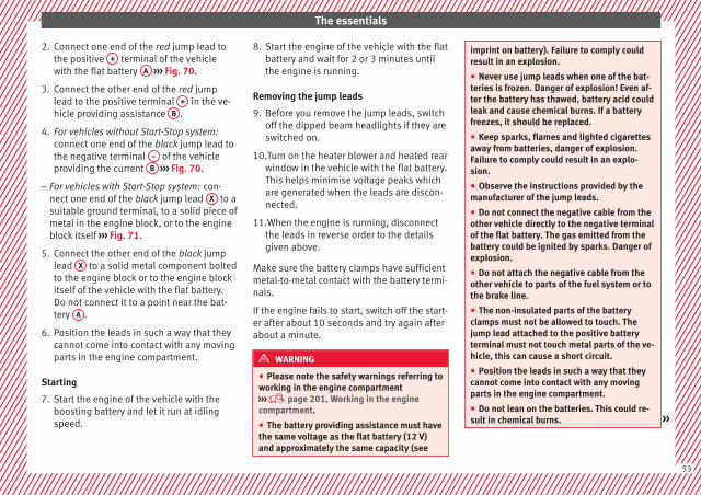
The essentials
2. Connect one end of the red jump lead tothe positive + terminal of the vehiclewith the flat battery A ››› Fig. 70.
3. Connect the other end of the red jumplead to the positive terminal + in the ve-hicle providing assistance B .
4. For vehicles without Start-Stop system:connect one end of the black jump lead tothe negative terminal – of the vehicleproviding the current B ››› Fig. 70.
– For vehicles with Start-Stop system: con-nect one end of the black jump lead X to asuitable ground terminal, to a solid piece ofmetal in the engine block, or to the engineblock itself ››› Fig. 71.
5. Connect the other end of the black jumplead X to a solid metal component boltedto the engine block or to the engine blockitself of the vehicle with the flat battery.Do not connect it to a point near the bat-tery A .
6. Position the leads in such a way that theycannot come into contact with any movingparts in the engine compartment.
Starting
7. Start the engine of the vehicle with theboosting battery and let it run at idlingspeed.
8. Start the engine of the vehicle with the flatbattery and wait for 2 or 3 minutes untilthe engine is running.
Removing the jump leads
9. Before you remove the jump leads, switchoff the dipped beam headlights if they areswitched on.
10.Turn on the heater blower and heated rearwindow in the vehicle with the flat battery.This helps minimise voltage peaks whichare generated when the leads are discon-nected.
11.When the engine is running, disconnectthe leads in reverse order to the detailsgiven above.
Make sure the battery clamps have sufficientmetal-to-metal contact with the battery termi-nals.
If the engine fails to start, switch off the start-er after about 10 seconds and try again afterabout a minute.
WARNING
● Please note the safety warnings referring toworking in the engine compartment››› page 201, Working in the enginecompartment.
● The battery providing assistance must havethe same voltage as the flat battery (12 V)and approximately the same capacity (see
imprint on battery). Failure to comply couldresult in an explosion.
● Never use jump leads when one of the bat-teries is frozen. Danger of explosion! Even af-ter the battery has thawed, battery acid couldleak and cause chemical burns. If a batteryfreezes, it should be replaced.
● Keep sparks, flames and lighted cigarettesaway from batteries, danger of explosion.Failure to comply could result in an explo-sion.
● Observe the instructions provided by themanufacturer of the jump leads.
● Do not connect the negative cable from theother vehicle directly to the negative terminalof the flat battery. The gas emitted from thebattery could be ignited by sparks. Danger ofexplosion.
● Do not attach the negative cable from theother vehicle to parts of the fuel system or tothe brake line.
● The non-insulated parts of the batteryclamps must not be allowed to touch. Thejump lead attached to the positive batteryterminal must not touch metal parts of the ve-hicle, this can cause a short circuit.
● Position the leads in such a way that theycannot come into contact with any movingparts in the engine compartment.
● Do not lean on the batteries. This could re-sult in chemical burns. »
53
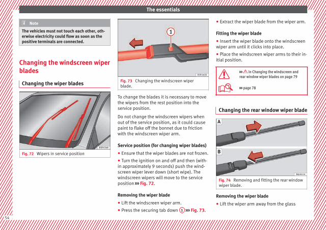
The essentials
Note
The vehicles must not touch each other, oth-erwise electricity could flow as soon as thepositive terminals are connected.
Changing the windscreen wiperblades
Changing the wiper blades
Fig. 72 Wipers in service position
Fig. 73 Changing the windscreen wiperblade.
To change the blades it is necessary to movethe wipers from the rest position into theservice position.
Do not change the windscreen wipers whenout of the service position, as it could causepaint to flake off the bonnet due to frictionwith the windscreen wiper arm.
Service position (for changing wiper blades)
● Ensure that the wiper blades are not frozen.
● Turn the ignition on and off and then (with-in approximately 9 seconds) push the wind-screen wiper lever down (short wipe). Thewindscreen wipers will move to the serviceposition ››› Fig. 72.
Removing the wiper blade
● Lift the windscreen wiper arm.
● Press the securing tab down 1 ››› Fig. 73.
● Extract the wiper blade from the wiper arm.
Fitting the wiper blade
● Insert the wiper blade onto the windscreenwiper arm until it clicks into place.
● Place the windscreen wiper arms to their in-itial position.
››› in Changing the windscreen andrear window wiper blades on page 79
››› page 78
Changing the rear window wiper blade
Fig. 74 Removing and fitting the rear windowwiper blade.
Removing the wiper blade
● Lift the wiper arm away from the glass
54

The essentials
● Slide the blade adapter in the direction ofthe arrow and remove the blade ››› Fig. 74 A.
Fitting the wiper blade
● With one hand, hold the top end of the wip-er arm.
● Place the blade as shown in ››› Fig. 74 Band slide the adapter along until it engages.
››› in Changing the windscreen andrear window wiper blades on page 79
››› page 78
55
Safety
Safety
Safe driving
Safety first!
This chapter contains important information,tips, suggestions and warnings that youshould read and consider for both your ownsafety and for your passengers' safety.
WARNING
● This manual contains important informa-tion about the operation of the vehicle, bothfor the driver and the passengers. The othersections of the on-board documentation alsocontain further information that you shouldbe aware of for your own safety and for thesafety of your passengers.
● Ensure that the on-board documentation iskept in the vehicle at all times. This is espe-cially important when lending or selling thevehicle to another person.
Advice about driving
Before setting off
For your own safety and the safety of yourpassengers, always note the following pointsbefore every trip:
– Make sure that the vehicle's lights and turnsignals are working properly.
– Check tyre pressure.
– Ensure that all windows provide a clear andgood view of the surroundings.
– Ensure that all luggage is correctly secured››› page 139.
– Make sure that no objects can interferewith the pedals.
– Adjust front seat, head restraint and rear vi-sion mirrors properly according to yoursize.
– Ensure that the passenger in the centralrear seat always has the head restraint inthe correct position for use.
– Instruct passengers to adjust the head re-straints according to their height.
– Protect children with appropriate childseats and properly applied seat belts››› page 72.
– Assume the correct sitting position. Instructyour passengers also to assume a propersitting position. ››› page 57.
– Fasten your seat belt securely. Instruct yourpassengers also to fasten their seat beltsproperly. ››› page 61.
What affects driving safety?
As a driver, you are responsible for yourselfand your passengers. When your concentra-tion or driving safety is affected by any cir-cumstance, you endanger yourself as well asothers on the road ››› , for this reason:
– Always pay attention to traffic and do notget distracted by passengers or telephonecalls.
– Never drive when your driving ability is im-paired (e.g. by medication, alcohol, drugs).
– Observe traffic laws and speed limits.
– Always reduce your speed as appropriatefor road, traffic and weather conditions.
– When travelling long distances, takebreaks regularly - at least every two hours.
– If possible, avoid driving when you are tiredor stressed.
WARNING
When driving safety is impaired during a trip,the risk of injury and accidents increases.
Safety equipment
Never put your safety or the safety of yourpassengers in danger. In the event of an acci-dent, the safety equipment may reduce the
56

Safe driving
risk of injury. The following list includes mostof the safety equipment in your SEAT:
● Three-point seat belts
● Belt tension limiter for the front and rearside seats
● Belt tensioners for the front seats
● Front airbags
● Side airbags in the front seat backrests,with chest and head protection
● “ISOFIX” anchor points for “ISOFIX” rearchild seat system
● Height-adjustable front head restraints
● Rear-centre head restraints with in-use po-sition and non-use position
● Adjustable steering column
The safety equipment mentioned aboveworks together to provide you and your pas-sengers with the best possible protection inthe event of an accident. However, thesesafety systems can only be effective if youand your passengers are sitting in a correctposition and use this equipment properly.
Safety is everyone's business!
Correct position for passengers
Correct sitting position for driver
Fig. 75 The proper distance between driverand steering wheel
Fig. 76 Correct head restraint position for thedriver.
For your own safety and to reduce the risk ofinjury in the event of an accident, we recom-
mend the following adjustments for the driv-er:
– Adjust the steering wheel so that there is adistance of at least 25 cm between thesteering wheel and the centre of your chest››› Fig. 75.
– Move the driver seat forwards or backwardsso that you are able to press the accelera-tor, brake and clutch pedals to the floorwith your knees still slightly angled ››› .
– Ensure that you can reach the highest pointof the steering wheel.
– Adjust the head restraint so that its upperedge is at the same level as the top of yourhead, or as close as possible to the samelevel as the top of your head ››› Fig. 76.
– Move the seat backrest to an upright posi-tion so that your back rests completelyagainst it.
– Fasten your seat belt securely ››› page 61.
– Keep both feet in the footwell so that youhave the vehicle under control at all times.
Adjustment of the driver seat ››› page 132.
WARNING
● An incorrect sitting position of the drivercan lead to severe injuries.
● Adjust the driver seat so that there is atleast 25 cm distance between the centre of »
57
Tech
nica
l dat
aA
dvic
eO
pera
tion
Emer
genc
ies
Saf
ety

Safety
the chest and the centre of the steeringwheel ››› Fig. 75. If distance is less than 25cm, the airbag system may not protect youproperly.
● If your physical constitution prevents youfrom maintaining the minimum distance of 25cm, contact a specialised workshop. Theworkshop will help you decide if special spe-cific modifications are necessary.
● When driving, always hold the steeringwheel with both hands on the outside of thering at the 9 o'clock and 3 o'clock positions.This reduces the risk of injury when the driverairbag is triggered.
● Never hold the steering wheel at the 12o'clock position, or in any other manner (e.g.in the centre of the steering wheel). In suchcases, if the airbag is triggered, you may sus-tain injuries to the arms, hands and head.
● To reduce the risk of injury to the driverduring sudden braking manoeuvres or an ac-cident, never drive with the backrest tilted farback! The airbag system and seat belts canonly provide optimal protection when thebackrest is in an upright position and thedriver is wearing his or her seat belt correct-ly.
● Adjust the head restraint properly to ach-ieve optimal protection.
Adjusting the steering wheel position
Read the additional information carefully››› page 13
WARNING
● Never adjust the position of the steeringwheel when the vehicle is moving, as thiscould cause an accident.
● Move the lever up firmly so the steeringwheel position does not accidentally changeduring driving. risk of accident!
● Make sure you are capable of reaching andfirmly holding the upper part of the steeringwheel: risk of accident!
● If you adjust the steering wheel so that itpoints towards your face, the driver airbagwill not protect you properly in the event ofan accident. Make sure that the steeringwheel points towards your chest.
Correct sitting position for front pas-senger
For your own safety and to reduce the risk ofinjury in the event of an accident, we recom-mend the following adjustments for the frontpassenger:
– Move the front passenger seat back as faras possible ››› .
– Move the seat backrest to an upright posi-tion so that your back rests completelyagainst it.
– Adjust the head restraint so that its upperedge is at the same level as the top of yourhead, or as close as possible to the samelevel as the top of your head ››› page 60.
– Always keep both feet in the footwell infront of the front passenger seat.
– Fasten your seat belt securely ››› page 61.
It is possible to deactivate the front passen-ger airbag in exceptional circumstances››› page 70.
Adjusting the front passenger seat››› page 12.
WARNING
● An incorrect sitting position of the frontpassenger can lead to severe injuries.
● Adjust the front passenger seat so thatthere is at least 25 cm between your chestand the dash panel. If distance is less than25 cm, the airbag system may not protect youproperly.
● If your physical constitution prevents youfrom maintaining the minimum distance of 25cm, contact a specialised workshop. Theworkshop will help you decide if special spe-cific modifications are necessary.
● Always keep your feet in the footwell whenthe vehicle is moving; never rest them on the
58

Safe driving
dash panel, out the window or on the seat. Anincorrect sitting position exposes you to anincreased risk of injury in case of a suddenbraking or an accident. If the airbag is trig-gered, you could sustain severe injuries dueto an incorrect sitting position.
● To reduce the risk of injury to the front pas-senger in events such as sudden braking ma-noeuvres or an accident, never travel with thebackrest tilted far back! The airbag systemand seat belts can only provide optimal pro-tection when the backrest is in an upright po-sition and the front passenger is wearing hisor her seat belt properly. The further the seatbackrests are tilted to the rear, the greaterthe risk of injury due to incorrect positioningof the belt web or to the incorrect sitting po-sition!
● Adjust the head restraint correctly in orderto achieve maximum protection.
Correct sitting position for rear seatpassengers
To reduce the risk of injury in the event of asudden braking manoeuvre or an accident,passengers on the rear seat bench must con-sider the following:
– Sit up straight.
– Adjust the head restraint to the correct po-sition ››› page 60.
– Always keep both feet in the footwell infront of the rear seat.
– Fasten your seat belt securely ››› page 61.
– Use an appropriate child restraint systemwhen you take children in the vehicle››› page 72.
WARNING
● If the passengers in the rear seats are notsitting properly, they could sustain severe in-juries.
● Adjust the head restraint correctly in orderto achieve maximum protection.
● Seat belts can only provide optimal protec-tion when seat backrests are in an uprightposition and the vehicle occupants are wear-ing their seat belts correctly. If passengers Inthe rear seats are not sitting in an upright po-sition, the risk of injury due to incorrect posi-tioning of the seat belt increases.
Examples of incorrect sitting posi-tions
Seat belts can provide optimal protection on-ly when the belt webs are properly posi-tioned. Incorrect sitting positions substan-tially reduce the protective function of seatbelts and increase the risk of injury due to in-correct seat belt position. As the driver, youare responsible for all passengers, especiallychildren.
– Never allow anyone to assume an incorrectsitting position in the vehicle while travel-ling ››› .
The following list contains examples of sit-ting positions that could be dangerous for allvehicle occupants. The list is not complete,but we would like to make you aware of thisissue.
Therefore, whenever the vehicle is in motion:
● Never stand in the vehicle.
● Never stand on the seats.
● Never kneel on the seats.
● Never tilt your seat backrest far to the rear.
● Never lean against the dash panel.
● Never lie on the rear bench.
● Never sit on the front edge of a seat.
● Never sit sideways.
● Never lean out of a window.
● Never put your feet out of a window.
● Never put your feet on the dash panel.
● Never put your feet on the surface of a seat.
● Do not allow anyone to travel in the foot-well.
● Never travel without wearing the seat belt.
● Do not allow anyone to travel in the lug-gage compartment. »
59
Tech
nica
l dat
aA
dvic
eO
pera
tion
Emer
genc
ies
Saf
ety

Safety
WARNING
● Any incorrect sitting position increases therisk of severe injuries.
● Sitting in an incorrect position exposes thevehicle occupants to severe injuries if airbagsare triggered, by striking a vehicle occupantwho has assumed an incorrect sitting posi-tion.
● Before the vehicle moves, assume the prop-er sitting position and maintain it throughoutthe trip. Before every trip, instruct your pas-sengers to sit properly and to stay in this po-sition during the trip ››› page 57, Correct posi-tion for passengers.
Correct adjustment of front head re-straints
Fig. 77 Correctly adjusted head restraint asviewed from the front and the side.
Properly adjusted head restraints are an im-portant part of passenger protection and canreduce the risk of injuries in most accidentsituations.
– Adjust the head restraint so that its upperedge is, as far as possible, at the same lev-el as the top of your head, or at the veryleast, at eye level ››› Fig. 77.
WARNING
● Travelling with the head restraints removedor improperly adjusted increases the risk ofsevere injuries. An improper adjustment ofthe head restraints may cause death in an ac-cident and increase the risk of suffering inju-ries during abrupt braking actions or unex-pected manoeuvres.
● The head restraints must always be adjus-ted according to the height of the passenger.
Correct adjustment of rear head re-straints
Fig. 78 Rear head restraint adjustment.
The rear head restraints have 2 positions:
● Raised position or position for use A
››› Fig. 78. In this position, the head restraintis used normally, protecting the occupant ofthe rear seats, along with the rear seat belts.
● Rest position, not in use B ››› Fig. 78. Thisposition improves the driver's rear visibility.
To fit the head restraint in position for useA , pull on the edges with both hands in the
direction of the arrow. To place it in rest posi-tion B , lower the head restraint.
WARNING
● Whenever a passenger is seated on the rearseats, the head restraint should be placed inthe position for use A .
60
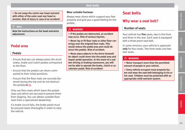
Seat belts
● Do not swap the centre rear head restraintwith either of the outer seat rear head re-straints. Risk of injury in case of an accident!
Note
Note the instructions on the head restraintsadjustment.
Pedal area
Pedals
– Ensure that you can always press the accel-erator, brake and clutch pedals unimpairedto the floor.
– Ensure that the pedals can return unim-paired to their initial positions.
– Ensure that the floor mats are securely fas-tened during the trip and do not obstructthe pedals ››› .
Only use floor mats which leave the pedalsclear and which are secured to prevent themfrom slipping. You can obtain suitable floormats from a specialised dealership.
If a brake circuit fails, the brake pedal mustbe pressed down thoroughly in order to stopthe vehicle.
Wear suitable footwear
Always wear shoes which support your feetproperly and give you a good feeling for thepedals.
WARNING
● If the pedals are obstructed, an accidentmay occur. Risk of serious injuries.
● Never lay or fit floor mats or other floor cov-erings over the original floor mats. Thiswould reduce the pedal area and could ob-struct the pedals. Risk of accident.
● Never place objects in the driver footwell.An object could move into the pedal area andimpair pedal operation. In the event of a sud-den driving or braking manoeuvre, you willnot be able to operate the brake, clutch or ac-celerator pedal. Risk of accident!
Seat belts
Why wear a seat belt?
Number of seats
Your vehicle has five seats, two in the frontand three in the rear. Each seat is equippedwith a three-point seat belt.
In some versions, your vehicle is approvedonly for four seats. Two front seats and tworear seats.
WARNING
● Never transport more than the permittedamount of people in your vehicle.
● Every vehicle occupant must properly fas-ten and wear the seat belt belonging to his orher seat. Children must be protected with anappropriate child restraint system.
61
Tech
nica
l dat
aA
dvic
eO
pera
tion
Emer
genc
ies
Saf
ety

Safety
Seat belt lamp*
Fig. 79 Warning lamp on the instrument pan-el.
The control lamp illuminates to remind thedriver to fasten his seat belt.
Before starting the vehicle:
– Fasten your seat belt securely.
– Instruct your passengers to fasten theirseat belts properly before driving off.
– Protect children by using a child seat ac-cording to the child's height and weight.
When the ignition is switched on, the controllamp in the instrument panel lights up* ifthe driver or passenger* have not fastenedtheir seat belts.
An audible warning signal will sound for afew seconds if the seat belts are not fastenedas the vehicle drives off and reaches a speedof more than approximately 25 km/h
(15 mph) or if the seat belts are unfastenedwhile the vehicle is in motion. The warninglamp will also flash .
The lamp goes out when the driver andpassenger seat belts are fastened with the ig-nition switched on.
The protective function of seat belts
Fig. 80 Drivers with properly worn seat beltswill not be thrown forward in the event of sud-den braking
Properly worn seat belts hold the occupantsin the proper position. These also help pre-vent uncontrolled movements that may resultin serious injury and reduce the risk of beingthrown out of the vehicle.
Vehicle occupants wearing their seat beltscorrectly benefit greatly from the ability of thebelts to absorb kinetic energy. In addition,the front part of your vehicle and other pas-
sive safety features (such as the airbag sys-tem) are designed to absorb the kinetic ener-gy released in a collision. Taken together, allthese features reduce the releasing kineticenergy and consequently, the risk of injury.This is why it is so important to fasten seatbelts before every trip, even when "just driv-ing around the corner".
Ensure that your passengers wear their seatbelts as well. Accident statistics have shownthat wearing seat belts is an effective meansof substantially reducing the risk of injuryand improving the chances of survival wheninvolved in a serious accident. Furthermore,properly worn seat belts improve the protec-tion provided by airbags in the event of anaccident. For this reason, wearing a seat beltis required by law in most countries.
Although your vehicle is equipped with air-bags, the seat belts must be fastened andworn. The front airbags, for example, are onlytriggered in some cases of head-on collision.The front airbags will not be triggered duringminor frontal or side collisions, rear-end colli-sions, rollovers or accidents in which the air-bag trigger threshold value in the control unitis not exceeded.
Therefore, you should always wear your seatbelt and ensure that all vehicle occupantshave fastened their seat belts properly beforeyou drive off!
62

Seat belts
Safety instructions on using seatbelts
– Always wear the seat belt as described inthis section.
– Ensure that the seat belts can be fastenedat all times and are not damaged.
WARNING
● If seat belts are worn incorrectly or not atall, the risk of severe injuries increases. Theoptimal protection from seat belts can beachieved only if you use them properly.
● Fasten your seat belt before every trip -even when driving in town. Other vehicle oc-cupants must also wear the seat belts at alltimes, otherwise they run the risk of being in-jured.
● The seat belt cannot offer its full protectionif the seat belt is not positioned correctly.
● Never allow two passengers (even children)to share the same seat belt.
● Always keep both feet in the footwell infront of your seat as long as the vehicle is inmotion.
● Never unbuckle a seat belt while the vehi-cle is in motion. Risk of fatal injury.
● The seat belt must never be twisted while itis being worn.
● The seat belt should never lie on hard orfragile objects (such as glasses or pens, etc.)because this can cause injuries.
● Do not allow the seat belt to be damaged orjammed, or to rub on any sharp edges.
● Never wear the seat belt under the arm orin any other incorrect position.
● Loose, bulky clothing (such as an overcoatover a jacket) impairs the proper fit and func-tion of the seat belts, reducing their capacityto protect.
● The slot in the seat belt buckle must not beblocked with paper or other objects, as thiscan prevent the latch plate from engaging se-curely.
● Never use seat belt clips, fastening rings orsimilar items to alter the position of the beltwebbing.
● Frayed or torn seat belts or damage to theconnections, belt retractors or parts of thebuckle could cause severe injuries in theevent of an accident. Therefore, you mustcheck the condition of all seat belts at regularintervals.
● Seat belts which have been worn in an acci-dent and stretched must be replaced by aspecialised workshop. Renewal may be nec-essary even if there is no apparent damage.The belt anchorage should also be checked.
● Do not attempt to repair a damaged seatbelt yourself. The seat belts must not be re-moved or modified in any way.
● The belts must be kept clean, otherwise theretractors may not work properly.
Head-on collisions and the laws ofphysics
Fig. 81 A driver not wearing a seat belt isthrown forward violently
Fig. 82 The unbelted passenger in the rearseat is thrown forward violently, hitting thedriver who is wearing a seat belt.
It is easy to explain how the laws of physicswork in the case of a head-on collision: whena vehicle starts moving, a type of energy »
63
Tech
nica
l dat
aA
dvic
eO
pera
tion
Emer
genc
ies
Saf
ety

Safety
called “kinetic energy” is created both in thepassengers and inside the vehicle.
The amount of “kinetic energy” depends onthe speed of the vehicle and the weight ofthe vehicle and its passengers. The higherthe speed and the greater the weight, themore energy there is to be “absorbed” in anaccident.
The most significant factor, however, is thespeed of the vehicle. If the speed doublesfrom 25 km/h (15 mph) to 50 km/h(30 mph), for example, the corresponding ki-netic energy is multiplied by four.
Because the vehicle occupants in our exam-ple are not restrained by seat belts, in theevent of crashing against a wall, all of the oc-cupants' kinetic energy will be absorbedsolely by said impact.
Even at speeds of 30 km/h (19 mph) to50 km/h (30 mph), the forces acting on bod-ies in a collision can easily exceed one tonne(1000 kg). At greater speed these forces areeven higher.
Vehicle occupants not wearing seat belts arenot “attached” to the vehicle. In a head-oncollision, they will move forward at the samespeed their vehicle was travelling just beforethe impact. This example applies not only tohead-on collisions, but to all accidents andcollisions.
Even at low speeds the forces acting on thebody in a collision are so great that it is notpossible to brace oneself with one's hands.In a frontal collision, unbelted passengersare thrown forward and will make violent con-tact with the steering wheel, dash panel,windscreen or whatever else is in the way››› Fig. 81.
It is also important for rear passengers towear seat belts properly, as they could other-wise be thrown forward violently through thevehicle interior in an accident. Passengers inthe rear seats who do not use seat belts en-danger not only themselves but also the frontoccupants ››› Fig. 82.
How to properly adjust yourseatbelt
Fastening and unfastening the seatbelt
Fig. 83 Positioning and removing the seatbelt buckle.
64
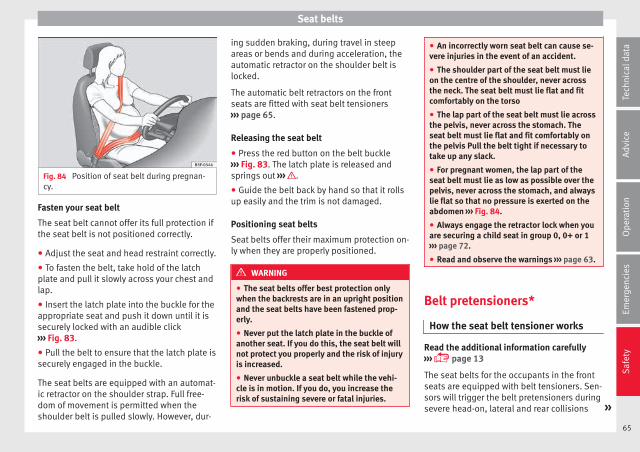
Seat belts
Fig. 84 Position of seat belt during pregnan-cy.
Fasten your seat belt
The seat belt cannot offer its full protection ifthe seat belt is not positioned correctly.
● Adjust the seat and head restraint correctly.
● To fasten the belt, take hold of the latchplate and pull it slowly across your chest andlap.
● Insert the latch plate into the buckle for theappropriate seat and push it down until it issecurely locked with an audible click››› Fig. 83.
● Pull the belt to ensure that the latch plate issecurely engaged in the buckle.
The seat belts are equipped with an automat-ic retractor on the shoulder strap. Full free-dom of movement is permitted when theshoulder belt is pulled slowly. However, dur-
ing sudden braking, during travel in steepareas or bends and during acceleration, theautomatic retractor on the shoulder belt islocked.
The automatic belt retractors on the frontseats are fitted with seat belt tensioners››› page 65.
Releasing the seat belt
● Press the red button on the belt buckle››› Fig. 83. The latch plate is released andsprings out ››› .
● Guide the belt back by hand so that it rollsup easily and the trim is not damaged.
Positioning seat belts
Seat belts offer their maximum protection on-ly when they are properly positioned.
WARNING
● The seat belts offer best protection onlywhen the backrests are in an upright positionand the seat belts have been fastened prop-erly.
● Never put the latch plate in the buckle ofanother seat. If you do this, the seat belt willnot protect you properly and the risk of injuryis increased.
● Never unbuckle a seat belt while the vehi-cle is in motion. If you do, you increase therisk of sustaining severe or fatal injuries.
● An incorrectly worn seat belt can cause se-vere injuries in the event of an accident.
● The shoulder part of the seat belt must lieon the centre of the shoulder, never acrossthe neck. The seat belt must lie flat and fitcomfortably on the torso
● The lap part of the seat belt must lie acrossthe pelvis, never across the stomach. Theseat belt must lie flat and fit comfortably onthe pelvis Pull the belt tight if necessary totake up any slack.
● For pregnant women, the lap part of theseat belt must lie as low as possible over thepelvis, never across the stomach, and alwayslie flat so that no pressure is exerted on theabdomen ››› Fig. 84.
● Always engage the retractor lock when youare securing a child seat in group 0, 0+ or 1››› page 72.
● Read and observe the warnings ››› page 63.
Belt pretensioners*
How the seat belt tensioner works
Read the additional information carefully››› page 13
The seat belts for the occupants in the frontseats are equipped with belt tensioners. Sen-sors will trigger the belt pretensioners duringsevere head-on, lateral and rear collisions »
65
Tech
nica
l dat
aA
dvic
eO
pera
tion
Emer
genc
ies
Saf
ety
Safety
only if the seat belt is being worn. This re-tracts and tightens the seat belts, reducingthe forward motion of the occupants.
The belt tensioners will not be triggered inthe event of minor collisions, if the vehicleoverturns, or in accidents where no majorforces act on the vehicle.
Note
● If the seat belt tensioners are triggered, afine dust is produced. This is normal and it isnot an indication of fire in the vehicle.
● The relevant safety requirements must beobserved when the vehicle or components ofthe system are scrapped. Specialised work-shops are familiar with these regulations,which are also available to you.
Service and disposal of belt tension-ers
The belt tensioners are components of theseat belts that are installed in the seats ofyour vehicle. If you work on the belt tension-ers or remove and install parts of the systemwhen performing other repair work, the seatbelt may be damaged. The consequence maybe that, in the event of an accident, the belttensioners function incorrectly or may notfunction at all.
So that the effectiveness of the seat belt ten-sioner is not reduced and that removed parts
do not cause any injuries or environmentalpollution, regulations, which are known tothe specialised workshops, must be ob-served.
WARNING
● Improper use or repairs not carried out byqualified mechanics increase the risk of se-vere or fatal injuries. The belt tensioners mayfail to trigger or may trigger in the wrong cir-cumstances.
● Never attempt to repair, adjust, remove orinstall parts of the belt tensioners or seatbelts.
● The seat belt tensioner, seat belt and auto-matic retractor cannot be repaired.
● Any work on the belt tensioners and seatbelts, including the removal and refitting ofsystem parts in conjunction with other repairwork, must be performed by a specialisedworkshop only.
● The belt tensioners will only provide pro-tection for one accident and must be changedif they have been activated.
Airbag system
Brief introduction
Why is it so important to wear a seatbelt and to sit correctly?
For the inflating airbags to achieve the bestprotection, the seat belt must always be wornproperly and the correct sitting position mustbe assumed.
The airbag system is not a substitute for seatbelts, but it is an integral part of the vehicle'soverall passive safety system. Please bear inmind that the airbag system can only work ef-fectively when the vehicle occupants arewearing their seat belts correctly and haveadjusted the head restraints properly. There-fore, it is most important to properly wear theseat belts at all times, not only because thisis required by law in most countries, but alsofor your safety ››› page 61, Why wear a seatbelt?.
The airbag inflates in a matter of seconds, soif you are not properly seated when the air-bag is triggered, you may sustain fatal inju-ries. Therefore, it is essential that all vehicleoccupants assume a correct sitting positionwhile travelling.
Sharp braking before an accident may causea passenger not wearing a seat belt to bethrown forward into the area of the deploying
66

Airbag system
airbag. In this case, the inflating airbag mayinflict critical or fatal injuries on the occu-pant. This also applies to children.
Always maintain the greatest possible dis-tance between yourself and the front airbag.This way, the front airbags can completelydeploy when triggered, providing their maxi-mum protection.
The most important factors that will triggeran airbag are: the type of accident, the angleof collision and the speed of the vehicle.
Whether or not the airbags are triggered de-pends primarily on the vehicle decelerationrate resulting from the collision and detectedby the control unit. If the vehicle decelerationoccurring during the collision and measuredby the control unit remains below the speci-fied reference values, the front, side and/orcurtain airbags will not be triggered. Take in-to account that the visible damage in a vehi-cle involved in an accident, no matter howserious, is not a determining factor for theairbags to have been triggered.
WARNING
● Wearing the seat belt incorrectly or assum-ing an incorrect sitting position can lead tocritical or fatal injuries.
● All vehicle occupants, including children,who are not properly belted can sustain criti-cal or fatal injuries if the airbag is triggered.Children up to 12 years old should always
travel on the rear seat. Never transport chil-dren in the vehicle if they are not restrainedor the restraint system is not appropriate fortheir age, size or weight.
● If you are not wearing a seat belt, or if youlean forward or to the side while travelling orassume an incorrect sitting position, there isa substantially increased risk of injury. Thisincreased risk of injury will be further in-creased if you are struck by an inflating air-bag.
● To reduce the risk of injury from an inflatingairbag, always wear the seat belt properly.
● Always adjust the front seats properly.
Description of airbag system
The airbag system mainly comprises (as pervehicle equipment):
● an electronic control and monitoring sys-tem (control unit)
● frontal airbags for driver and passenger,
● side airbags,
● curtain airbags,
● a control lamp on the dash panel››› page 68.
● key-operated switch for front passenger air-bag,
● a control lamp for disabling/enabling thefront passenger airbag.
The airbag system operation is monitoredelectronically. The airbag control lamp will il-luminate for a few seconds every time the ig-nition is switched on (self-diagnosis).
There is a fault in the system if the controllamp :
● does not light up when the ignition isswitched on ››› page 68,
● turns off after 4 seconds after the ignitionis switched on
● turns off and then lights up again after theignition is switched on
● illuminates or flashes while the vehicle ismoving.
The airbag system is not triggered if:
● the ignition is switched off
● there is a minor frontal collision
● there is a minor side collision
● there is a rear-end collision
● the vehicle turns over.
WARNING
● The seat belts and airbags can only providemaximum protection if the occupants areseated correctly ››› page 57, Correct positionfor passengers.
● If a fault has occurred in the airbag system,have the system checked immediately by aspecialised workshop. Otherwise, during a »
67
Tech
nica
l dat
aA
dvic
eO
pera
tion
Emer
genc
ies
Saf
ety

Safety
frontal collision the system might not triggercorrectly or may fail to trigger at all.
Airbag activation
The airbags deploy extremely rapidly, withinthousandths of a second, to provide addi-tional protection in the event of an accident.A fine dust may develop when the airbag de-ploys. This is normal and it is not an indica-tion of fire in the vehicle.
The airbag system is only ready to functionwhen the ignition is on.
In special accidents instances, several air-bags may activate at the same time.
In the event of minor head-on and side colli-sions, rear-end collisions, overturning or roll-over of the vehicle, airbags do not activate.
Activation factors
The conditions that lead to the airbag systemactivating in each situation cannot be gener-alised. Some factors play an important role,such as the properties of the object the vehi-cle hits (hard/soft), angle of impact, vehiclespeed, etc.
Deceleration trajectory is key for airbag acti-vation.
The control unit analyses the collision trajec-tory and activates the respective restraintsystem.
If the deceleration rate is below the prede-fined reference value in the control unit theairbags will not be triggered, even thoughthe accident may cause extensive damage tothe car.
The following airbags are triggered in seri-ous head-on collisions
● Driver airbag.
● Front passenger front airbag
The following airbags are triggered in seri-ous side-on collisions
● Front side airbag on the side of the acci-dent.
● Rear side airbag on the side of the acci-dent.
● Curtain (head) airbag on the side of the ac-cident.
In an accident with airbag activation:
● the interior lights switch on (if the interiorlight switch is in the courtesy light position);
● the hazard warning lights switch on;
● all doors are unlocked;
● the fuel supply to the engine is cut.
Airbag control lamp and seat belt ten-sioner
The control lamp monitors all airbags andseat belt tensioners in the vehicle, includingcontrol units and wiring connections.
Monitoring of airbag and belt tensioner sys-tem
Both the airbag and belt tensioner systemsoperation is constantly monitored electroni-cally. The control lamp will light up for afew seconds every time the ignition is switch-ed on (self-diagnosis).
The system must be checked when the con-trol lamp :
● does not light up when the ignition isswitched on,
● turns off after 4 seconds after the ignitionis switched on
● turns off and then lights up again after theignition is switched on
● illuminates or flashes while the vehicle ismoving.
In the event of a malfunction, the warninglamp remains on continuously. Have the air-bag system inspected immediately by a spe-cialised workshop.
68

Airbag system
If any of the airbags are disabled by a Techni-cal Service, the warning lamp flashes for sev-eral more seconds after verification and willturn off if there is no fault.
WARNING
● If there is a malfunction, the airbag andbelt tensioner system cannot properly per-form its protective function.
● If a malfunction occurs, have the systemchecked immediately by a specialised work-shop. Otherwise, in the event of an accident,the airbag system and belt tensioners maynot be triggered, or may not be triggered cor-rectly.
Airbag safety instructions
Front airbags
Read the additional information carefully››› page 14.
WARNING
● The seat belts and airbags can only providemaximum protection if the occupants areseated correctly ››› page 57, Correct positionfor passengers.
● The deployment space between the frontpassengers and the airbags must not in anycase be occupied by other passenger, petsand objects.
● The airbags provide protection for just oneaccident; replace them once they have de-ployed.
● It is also important not to attach any ob-jects such as cup holders or telephonemountings to the surfaces covering the air-bag units.
● Do not attempt to modify components ofthe airbag system in any way.
Side airbags*
Read the additional information carefully››› page 15.
WARNING
● If you do not wear a seat belt, if you leanforward, or are not seated correctly while thevehicle is in motion, you are at a greater riskof injury if the side airbag system is triggeredin an accident.
● In order for the side airbags to provide theirmaximum protection, the prescribed sittingposition must always be maintained withseat belts fastened while travelling.
● Occupants of the outer seats must nevercarry any objects or pets in the deploymentspace between them and the airbags, or al-low children or other passengers to travel inthis position. It is also important not to at-tach any accessories (such as cup holders) to
the doors. This would impair the protectionoffered by the side airbags.
● The built-in coat hooks should be used onlyfor lightweight clothing. Do not leave anyheavy or sharp-edged objects in the pockets.
● Great forces, such as hard blows or kicks,must not be exerted upon the backrest bol-ster because the system may be damaged. Inthis case, the side airbags would not be trig-gered.
● Under no circumstances should protectivecovers be fitted over seats with side airbagsunless the covers have been approved for usein your vehicle. Because the airbag deploysfrom the side of the backrest, the use of con-ventional seat covers would obstruct the sideairbag, seriously reducing the airbag's effec-tiveness.
● Any damage to the original seat upholsteryor around the seams of the side airbag unitsmust be repaired immediately by a special-ised workshop.
● The airbags provide protection for just oneaccident; replace them once they have de-ployed.
● Any work on the side airbag system or re-moval and installation of the airbag compo-nents for other repairs (such as removal ofthe front seat) should only be performed by aspecialised workshop. Otherwise, faults mayoccur during the airbag system operation.
● Do not attempt to modify components ofthe airbag system in any way. »
69
Tech
nica
l dat
aA
dvic
eO
pera
tion
Emer
genc
ies
Saf
ety

Safety
● The side and head airbags are managedthrough sensors located in the interior of thefront doors. To ensure the correct operation ofthe side and curtain (head) airbags neitherthe doors nor the door panels should bemodified in any way (e.g. fitting loudspeak-ers). If the front door is damaged, the airbagsystem may not work correctly. All work car-ried out on the front door must be done in aspecialised workshop.
● In a side-on collision the side airbags willnot work if the sensors do not correctly meas-ure the pressure increase on the interior ofthe doors, due to air escaping through theareas with holes or openings in the door pan-el.
● Never drive if the interior door panels havebeen removed or if the panels have not beencorrectly fitted.
● Never drive the vehicle if the loudspeakersin the door panels have been removed, un-less the holes left by the loudspeakers havebeen closed properly.
● Always check that the openings are closedor covered if additional loudspeakers or otherequipment are fitted inside the door panels.
● Any work carried out to the doors should bemade in an authorised specialised workshop.
Curtain airbags*
Read the additional information carefully››› page 15.
WARNING
The airbag is deployed at high speed in frac-tions of a second.
● Do not obstruct the head-protection airbagdeployment areas.
● Never secure objects over the curtain air-bag cover or in its deployment area.
● Occupants of the front seats and rear sideseats must never carry any other people, ani-mals or objects in the deployment space be-tween them and the airbags. Make sure thatall the vehicle occupants, including children,observe this.
● The clothes hangers are intended only forlight articles of clothing. Do not leave anyheavy or sharp-edged objects in the pockets.
● Do not mount accessories on the doors.
● Use only sun blinds which have been ex-pressly approved for use in your vehicle.
● Do not turn the sun blinds towards the win-dows if there are objects, e.g. pens or garageremote controls, secured to them.
Deactivating airbags
Deactivation of front passenger frontairbag*
Fig. 85 In the glove compartment: Switch foractivating and deactivating the front passen-ger airbag
Fig. 86 Centre side of dash panel: controllamp for deactivated front passenger airbagin centre console
70

Airbag system
Read the additional information carefully››› page 14
If you fit a rear-facing child seat to the frontpassenger seat, the front passenger front air-bag must be de-activated.
When the front passenger airbag is deactiva-ted, this means that only the front passengerfront airbag is deactivated. All the other air-bags in the vehicle remain activated.
Activating the front passenger front airbag
– Switch the ignition off.
– Open the glove compartment on the frontpassenger side.
– Insert the key into the slot of the switch fordeactivating the front passenger airbag››› Fig. 85. About 3/4 of the key should en-ter, as far as it will go.
– Then turn the key gently to the position.Do not force it if you feel resistance, andmake sure you have inserted the key fully.
– When the ignition is switched on, checkwhether the control lamp on the dash panel does ››› Fig. 86 notlight up ››› .
WARNING
● It is the driver's responsibility to ensurethat the key-operated switch is set to the cor-rect position.
● You should deactivate the front passengerfront airbag only if you have to use a rear-fac-ing child seat in exceptional cases››› page 72, Transporting children safely.
● Never install a child seat facing backwardson the front passenger seat unless the frontpassenger front airbag has been disabled.Otherwise, there is a risk of death.
● As soon as the child seat is no longer nee-ded on the front passenger seat, enable thefront passenger front airbag again.
● Only deactivate the front passenger frontairbag when the ignition is off, otherwise afault may occur in the airbag system, whichcould cause the airbag to not deploy properlyor not deploy at all in case of an accident.
● Never leave the key in the airbag disablingswitch as it could get damaged or enable ordisable the airbag during driving.
● When the passenger airbag is deactivated,if the control lamp is notcontinuously lit up when the front passengerairbag is disabled, there may be a fault in theairbag system:
– Have the airbag system inspected imme-diately by a specialised workshop.
– Do not use a child seat on the front pas-senger seat! The front passenger frontairbag could be triggered in the event ofan accident, even if there is a fault in thesystem and, as a result, a child could sus-tain serious or fatal injuries.
– It is unpredictable whether the front pas-senger airbag will deploy in the event of
an accident. Warn all your passengers ofthis.
71
Tech
nica
l dat
aA
dvic
eO
pera
tion
Emer
genc
ies
Saf
ety

Safety
Transporting children safely
Safety for children
Introduction
For safety reasons, as we have learned fromaccident statistics, we recommend that chil-dren under 12 years of age travel in the rearseats. Depending on their age, height andweight, children travelling in rear seats mustuse a child seat or a seat belt. For safety rea-sons, the child seat should be installed in therear seat, behind the front passenger seat orin the centre back seat.
The physical laws involved and the forcesacting in a collision apply also to children››› page 63. But unlike adults, children do nothave fully developed muscle and bone struc-tures. This means that children are subject toa greater risk of injury.
To reduce the risk of injuries, children mustalways use special child restraint systemswhen travelling in the vehicle.
We recommend the use of child safety prod-ucts from the SEAT Original Accessories Pro-gramme, which includes systems for all agesmade by “Peke” (not for all countries).
These systems have been especially de-signed and approved, complying with theECE-R44. regulation.
Follow the manufacturer's instructions andobserve any statutory requirements when in-stalling and using child seats. Always readand note ››› page 72.
We recommend you always carry the manu-facturer's Child Seat Instruction Manual to-gether with the on-board documentation.
Important information regarding thefront passenger's airbag
Read the additional information carefully››› page 16.
Read and always observe the safety informa-tion included in the following chapters:
● Safety distance with respect to the passen-ger airbag ››› page 66.
● Objects between the passenger and thepassenger side airbag ››› in Front airbagson page 69.
The passenger side front airbag, when ena-bled, is a serious risk for a child that is facingbackward since the airbag can strike the seatwith such force that it can cause serious orfatal injuries. Children up to 12 years oldshould always travel on the rear seat.
Therefore we strongly recommend you totransport children on the rear seats. This isthe safest location in the vehicle. Alternative-ly, the front passenger airbag can be disa-
bled with a key-operated switch ››› page 70.When transporting children, use a child seatappropriate to the age and size of each child.
WARNING
● If a child seat is secured to the front pas-senger seat, the risk to the child of sustain-ing critical or fatal injuries in the event of anaccident increases.
● An inflating front passenger airbag canstrike the rear-facing child seat and project itwith great force against the door, the roof orthe backrest.
● Never install a child seat facing backwardson the front passenger seat unless the frontpassenger front airbag has been disabled.Risk of potentially fatal injuries to the child!However, if it is necessary, in exceptional ca-ses, to transport a child in the front passen-ger seat, the front passenger front airbagmust always be disabled ››› page 70, Deacti-vation of front passenger front airbag*. If thefront passenger seat has a height adjustmentoption, move it to the highest position.
● For those vehicles that do not include a keylock switch to deactivate the airbag, the vehi-cle must be taken to a technical service.
● All vehicle occupants, especially children,must assume the proper sitting position andbe properly belted in while travelling.
● Never hold children or babies on your lap,this can result in potentially fatal injuries tothe child!
72

Transporting children safely
● Never allow a child to be transported in avehicle without being properly secured, or tostand up or kneel on a seat while travelling.In an accident, the child could be flungthrough the vehicle, causing possibly fatal in-juries to themselves and to the other vehicleoccupants.
● If children assume an improper sitting posi-tion when the vehicle is moving, they exposethemselves to greater risk of injury in theevent of a sudden braking manoeuvre or in anaccident. This is particularly important if thechild is travelling on the front passenger seatand the airbag system is triggered in an acci-dent; as this could cause serious injury oreven death.
● A suitable child seat can protect your child!
● Never leave a child alone in the child seator inside the vehicle because depending onthe season, very high temperatures may bereached inside a parked vehicle, which couldbe fatal.
● Children who are less than 1.5 metres tallmust not wear a normal seat belt without achild seat, as this could cause injuries to theabdominal and neck areas during a suddenbraking manoeuvre or in an accident.
● Do not allow the seat belt to become twis-ted and the seat belt should be properly inplace ››› page 61.
● Only one child may occupy a child seat››› page 73, Child seats.
● When a child seat is mounted in the rearseats, the door child-proof lock should be ac-tivated ››› page 115.
Child seats
Safety instructions
Read the additional information carefully››› page 16.
WARNING
When travelling, children must be secured inthe vehicle with a restraint system suitablefor age, weight and size.
● Read and always observe information andwarnings concerning the use of child seats››› page 72.
WARNING
The retaining rings are designed only for usewith “ISOFIX” and Top Tether* system childseats.
● Never secure other child seats that do nothave the “ISOFIX” or Top Tether* system, orretaining belts or objects to the fasteningrings - this can result in potentially fatal inju-ries to the child.
● Ensure that the child seat is secured cor-rectly using the “ISOFIX” and Top Tether* se-curing rings.
WARNING
An undue installation of the safety seat willincrease the risk of injury in the event of acrash.
● Never tie the retainer strap to a hook in theluggage compartment.
● Never secure or tie luggage or other itemsto the lower anchorages (ISOFIX) or the upperones (Top Tether).
Categorisation of child seats intogroups
Only use child seats that are officially ap-proved and suitable for the child.
Child seats are subject to the regulation ECE-R 44. ECE-R stands for: Economic Commis-sion for Europe Regulation.
The child seats are grouped into 5 catego-ries:
Group 0: Up to 10 kg (up to around 9months)
Group 0+: Up to 13 kg (up to around 18months)
Group 1: from 9 to 18 kg (up to approx. 4years old)
Group 2: from 15 to 25 kg (up to approx. 7years old) »
73
Tech
nica
l dat
aA
dvic
eO
pera
tion
Emer
genc
ies
Saf
ety

Safety
Group 3: From 22 to 36 kg (over around 7years old)
Child seats that have been tested and ap-proved under the ECE R44 standard bear thetest mark on the seat (the letter E in a circlewith the test number below it).
Follow the manufacturer's instructions andobserve any statutory requirements when in-stalling and using child seats.
We recommend you to always include themanufacturer's Child Seat Instruction Manualtogether with the on-board documentation.
SEAT recommends you use child seats fromthe Original Accessories Catalogue. Thesechild seats have been designed and testedfor use in SEAT vehicles. You can find theright child seat for your model and age groupat SEAT dealers.
WARNING
Read and always observe information andwarnings concerning the use of child seats››› page 72.
74

Self-help
Emergencies
Self-help
Emergency equipment
Emergency warning triangle*
Fig. 87 IBIZA ST model: Housing for the emer-gency warning triangle in the luggage com-partment.
The use of reflective warning triangles isobligatory in emergencies in some countries.As are the first aid kit and a set of spare lightbulbs.
The warning triangle is under the storagecompartment which is located under the lug-gage compartment floor.
Note
● The warning triangle is not part of the vehi-cle's standard equipment.
● The warning triangle should meet legal re-quirements.
First-aid kit and fire extinguisher*
Fig. 88 IBIZA ST model: Housing for the first-aid kit in the luggage compartment.
The first-aid kit can go in the storage com-partment which is located under the luggagecompartment floor.
The fire extinguisher* is attached to the lug-gage compartment carpet with Velcro.
Note
● The first-aid kit and the fire extinguisherare not part of the vehicle's standard equip-ment.
● The first aid kit must comply with legal re-quirements.
● Observe the expiry date of the contents ofthe first aid kit. After it has expired youshould purchase a new one.
● The fire extinguisher must comply with le-gal requirements.
● Ensure that the fire extinguisher is fullyfunctional. The fire extinguisher should,therefore, be checked regularly. The stickeron the fire extinguisher will inform you of thenext date for checking.
● Before acquiring accessories and emergen-cy equipment see the instructions in “Acces-sories and spares” ››› page 190.
Vehicle tools
Read the additional information carefully››› page 47
Some of the items listed are only provided incertain model versions, or are optional ex-tras.
WARNING
● The factory-supplied jack is only designedfor changing wheels on this model. On no ac-count attempt to use it for lifting heavier ve-hicles or other loads. Risk of injury.
● Use the jack only on a firm, level ground. »
75
Tech
nica
l dat
aA
dvic
eO
pera
tion
Emer
genc
ies
Saf
ety
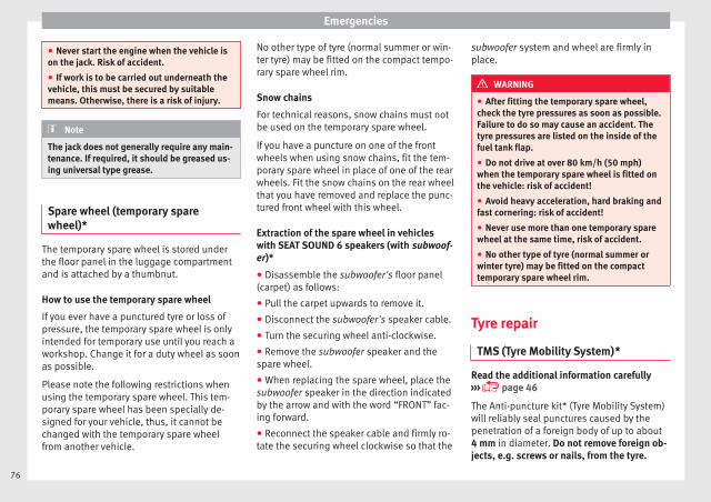
Emergencies
● Never start the engine when the vehicle ison the jack. Risk of accident.
● If work is to be carried out underneath thevehicle, this must be secured by suitablemeans. Otherwise, there is a risk of injury.
Note
The jack does not generally require any main-tenance. If required, it should be greased us-ing universal type grease.
Spare wheel (temporary sparewheel)*
The temporary spare wheel is stored underthe floor panel in the luggage compartmentand is attached by a thumbnut.
How to use the temporary spare wheel
If you ever have a punctured tyre or loss ofpressure, the temporary spare wheel is onlyintended for temporary use until you reach aworkshop. Change it for a duty wheel as soonas possible.
Please note the following restrictions whenusing the temporary spare wheel. This tem-porary spare wheel has been specially de-signed for your vehicle, thus, it cannot bechanged with the temporary spare wheelfrom another vehicle.
No other type of tyre (normal summer or win-ter tyre) may be fitted on the compact tempo-rary spare wheel rim.
Snow chains
For technical reasons, snow chains must notbe used on the temporary spare wheel.
If you have a puncture on one of the frontwheels when using snow chains, fit the tem-porary spare wheel in place of one of the rearwheels. Fit the snow chains on the rear wheelthat you have removed and replace the punc-tured front wheel with this wheel.
Extraction of the spare wheel in vehicleswith SEAT SOUND 6 speakers (with subwoof-er)*
● Disassemble the subwoofer's floor panel(carpet) as follows:
● Pull the carpet upwards to remove it.
● Disconnect the subwoofer's speaker cable.
● Turn the securing wheel anti-clockwise.
● Remove the subwoofer speaker and thespare wheel.
● When replacing the spare wheel, place thesubwoofer speaker in the direction indicatedby the arrow and with the word “FRONT” fac-ing forward.
● Reconnect the speaker cable and firmly ro-tate the securing wheel clockwise so that the
subwoofer system and wheel are firmly inplace.
WARNING
● After fitting the temporary spare wheel,check the tyre pressures as soon as possible.Failure to do so may cause an accident. Thetyre pressures are listed on the inside of thefuel tank flap.
● Do not drive at over 80 km/h (50 mph)when the temporary spare wheel is fitted onthe vehicle: risk of accident!
● Avoid heavy acceleration, hard braking andfast cornering: risk of accident!
● Never use more than one temporary sparewheel at the same time, risk of accident.
● No other type of tyre (normal summer orwinter tyre) may be fitted on the compacttemporary spare wheel rim.
Tyre repair
TMS (Tyre Mobility System)*
Read the additional information carefully››› page 46
The Anti-puncture kit* (Tyre Mobility System)will reliably seal punctures caused by thepenetration of a foreign body of up to about4 mm in diameter. Do not remove foreign ob-jects, e.g. screws or nails, from the tyre.
76

Self-help
After inserting the sealant residue in the tyre,you must again check the tyre pressure about10 minutes after starting the engine.
You should only use the tire mobility set ifthe vehicle is parked in a safe place, you arefamiliar with the procedure and you have thenecessary tire mobility set! Otherwise, youshould seek professional assistance.
Do not use the tyre sealant in the followingcases:
● If the wheel rim has been damaged.
● In outside temperatures below -20°C (-4°F).
● In the event of cuts or perforations in thetyre greater than 4 mm.
● If you have been driving with very low pres-sure or a completely flat tyre.
● If the sealant bottle has passed its use bydate.
WARNING
Using the tyre mobility system can be dan-gerous, especially when filling the tyre at theroadside. Please observe the following rulesto minimise the risk of injury:
● Stop the vehicle safely as soon as possible.Park it at a safe distance from surroundingtraffic to fill the tyre.
● Ensure the ground on which you park is flatand solid.
● All passengers and particularly childrenmust keep a safe distance from the work area.
● Turn on the hazard warning lights to warnother road users.
● Use the tyre mobility system only if you arefamiliar with the necessary procedures. Oth-erwise, you should seek professional assis-tance.
● The tyre mobility set is intended for tempo-rary emergency use only until you can reachthe nearest specialised workshop.
● Replace the repaired tyre with the tyre mo-bility set as soon as possible.
● The sealant is a health hazard and must becleaned immediately if it comes into contactwith the skin.
● Always keep the tyre mobility set out of thereach of small children.
● Never use a jack, even if it has been ap-proved for your vehicle.
● Always stop the engine, apply the hand-brake lever firmly and engage gear if using amanual gearbox, in order to reduce the risk ofvehicle involuntary movement.
WARNING
A tyre filled with sealant does not have thesame performance properties as a conven-tional tyre.
● Never drive faster than 80 km/h (50 mph).
● Avoid heavy acceleration, hard braking andfast cornering.
● Drive for only 10 minutes at a maximumspeed of 80 km/h (50 mph) and then checkthe tyre.
For the sake of the environment
Dispose of used or expired sealant observingany legal requirements.
Note
● A new bottle of sealant can be purchased atSEAT dealerships.
● Take into account the separate instructionmanual of the tyre mobility set* manufactur-er.
Contents of the tyre mobility set*
Fig. 89 Standard representation: Contents ofthe tyre mobility system. »
77
Tech
nica
l dat
aA
dvic
eO
pera
tion
Emer
genc
ies
Saf
ety

Emergencies
The tyre mobility set is located underneaththe floor covering in the luggage compart-ment. It includes the following components››› Fig. 89:
Tyre valve remover
Sticker indicating maximum speed “max.80 km/h” or “max. 50 mph”
Filler tube with cap
Air compressor
Tube for inflating tyres
Warning provided by tyre pressure moni-toring system (it can also be integrated inthe compressor).
Air bleed screw (in its place, the compres-sor may have a button).
ON/OFF switch
12 volt connector
Bottle of sealant
Spare tyre valve
The valve insert remover 1 has a gap at thelower end for a valve insert. The valve insertcan only be screwed or unscrewed in thisway. This also applies to its replacement part11 .
WARNING
When inflating the wheel, the air compressorand the inflator tube may become hot.
● Protect hands and skin from hot parts.
1
2
3
4
5
6
7
8
9
10
11
● Do not place the hot flexible inflator tube orhot air compressor on flammable material.
● Allow them to cool before storing the de-vice.
● If it is not possible to inflate the tyre to atleast 2.0 bars (29 psi / 200 kPa), the tyre istoo badly damaged. The sealant is not in agood condition to seal the tyre. Do not con-tinue driving. Seek specialist assistance.
CAUTION
Switch off the air compressor after a maxi-mum of 8 operational minutes to avoid over-heating! Before switching on the air compres-sor again, let it cool for several minutes.
Check after 10 minutes of driving
Screw in the inflator tube ››› Fig. 89 5 againand check the pressure on the gauge 6 .
1.3 bar (19 psi / 130 kPa) and lower:
● Stop the vehicle! The tyre cannot be sealedsufficiently with the tyre mobility set.
● You should obtain professional assistance››› .
1.4 bar (20 psi / 140 kPa) and higher:
● Set the tyre pressure to the correct valueagain.
● Carefully resume your journey, without ex-ceeding 80 km/h (50 mph), until you reachthe nearest specialised workshop and re-place the tyre.
WARNING
Driving with an unsealed tyre is dangerousand can cause accidents and serious injury.
● Do not continue driving if the tyre pressureis 1.3 bar (19 psi / 130 kPa) and lower.
● Seek specialist assistance.
Changing the windscreen wiperblades
Changing the windscreen and rearwindow wiper blades
Read the additional information carefully››› page 54.
Perfect wiper blade condition is essential forclear vision. Damaged wiper blades shouldbe replaced immediately.
The windscreen wiper blades are supplied asstandard with a layer of graphite. This layer isresponsible for ensuring that the wipe is si-lent. If the graphite layer is damaged, thenoise of the water as it is wiped across thewindscreen will be louder.
78

Self-help
Check the condition of the wiper blades regu-larly. If the wipers scrape across the glass,they should be changed if they are damaged,or cleaned if they are dirty ››› .
If this does not produce the desired results,the setting angle of the windscreen wiperarms might be incorrect. They should bechecked by a specialised workshop and cor-rected if necessary.
WARNING
Do not drive unless you have good visibilitythrough all windows!
● Clean the windscreen wiper blades and allwindows regularly.
● The wiper blades should be changed onceor twice a year.
CAUTION
● Damaged or dirty windscreen wipers couldscratch the glass.
● Never use fuel, nail varnish remover, paintthinner or similar products to clean the win-dows. This could damage the windscreenwiper blades.
● Never move any windscreen wiper by hand.This could cause damage.
● To prevent damage to the bonnet and thewindscreen wiper arms, the latter should onlybe lifted off the windscreen when in serviceposition.
Note
● The windscreen wiper arms can be movedto the service position only when the bonnetis properly closed.
● You can also use the service position, forexample, if you want to fix a cover over thewindscreen in the winter to keep it clear ofice.
Towing or tow-starting
Notes
Read the additional information carefully››› page 51
Please observe the following points if youuse a tow rope:
Notes for the driver of the towing vehicle
– Move the vehicle slowly until the cable istaut. Then accelerate gradually.
– Begin and change gears cautiously. If youare driving an automatic vehicle, accelerategently.
– Remember that the brake servo and powersteering are not working in the vehicle youare towing. Brake sooner than normal andpressing the pedal gently.
Notes for the driver of the towed vehicle
– Ensure that the tow rope remains taut at alltimes when towing.
Towing vehicles with an automatic gearbox
● Put the selector lever into position “N”.
● Do not drive faster than 50 km/h (31 mph).
● Do not tow further than 50 km.
● If a breakdown vehicle is used, the vehiclemust be towed with the front wheels raised.
WARNING
If the vehicle has no electrical power, thebrake lights, turn signals and all other lightswill no longer function. Do not have the vehi-cle towed away. Failure to follow this instruc-tion could result in an accident.
WARNING
Vehicle handling and braking capacitychange considerably during towing. Pleaseobserve the following instructions to mini-mise the risk of serious accidents and injury:
● As the driver of the vehicle being towed:
– You should depress the brake much hard-er as the brake servo does not operate.Pay the utmost attention to avoid crash-ing into the towing vehicle.
– More strength is required at the steeringwheel as the power steering does not op-erate when the engine is switched off. »
79
Tech
nica
l dat
aA
dvic
eO
pera
tion
Emer
genc
ies
Saf
ety

Emergencies
● As the driver of the towing vehicle:
– Accelerate with particular care and cau-tion.
– Avoid sudden braking and manoeuvres.
– Brake earlier than usual and moresmoothly.
CAUTION
When tow-starting, fuel could enter the cata-lytic converter and damage it.
Note
● Observe legal requirements when towing ortow-starting.
● Switch on the hazard warning lights of bothvehicles. However, observe any regulationsto the contrary.
● For technical reasons, vehicles with an au-tomatic gearbox must not be tow-started.
● If there is no lubricant in the gearbox as theresult of a fault, you must raise the drivenwheels while the vehicle is being towed.
● If the vehicle has to be towed more than50 km (30 miles), the front wheels should beraised during towing, and towing should becarried out by a qualified person.
● The steering wheel is locked when the vehi-cle has no electrical power. The vehicle mustthen be towed with the front wheels raised.Towing should be carried out by a qualifiedperson.
● The towline anchorage should always bekept in the vehicle.
Towline anchorages
Fig. 90 Towline anchorage at the front of thevehicle
Read the additional information carefully››› page 51
Fitting the front towline anchorage
– Take the towline anchorage from the on-board tool set.
– Remove the front cover by pressing downon its left-hand side. For FR finishes, pressdown and pull outwards. For the rest of theSport finishes, remove the cover by insert-ing a screwdriver into the lower slot andlevering gently.
– Bolt the anchorage to its limit to the left, inthe direction of the arrow ››› Fig. 90.
Rear towline anchorage
There is a towline anchorage at the rear onthe right below the rear bumper.
80

Fuses and bulbs
Fuses and bulbs
Fuses
Introduction
Due to the constant updating of vehicles,fuse assignments based on equipment andthe use of the same fuse for various electricalcomponents, it is not possible to provide anup-to-date summary of the fuse positions forthe electrical components at the time thismanual was printed. For detailed informationabout the fuse positions, please consult atechnical service.
In general, a fuse can be assigned to variouselectrical components. Likewise, an electricalcomponent can be protected by severalfuses.
Only replace fuses when the cause of theproblem has been solved. If a newly insertedfuse blows after a short time, you must havethe electrical system checked by a special-ised workshop as soon as possible.
WARNING
The high voltages in the electrical system cangive serious electrical shocks, causing burnsand even death!
● Never touch the electrical wiring of the igni-tion system.
● Take care not to cause short circuits in theelectrical system.
WARNING
Using unsuitable fuses, repairing fuses orbridging a current circuit without fuses cancause a fire and serious injury.
● Never use a fuse with a higher value. Onlyreplace fuses with a fuse of the same amper-age (same colour and markings) and size.
● Never repair a fuse.
● Never replace a fuse by a metal strip, stapleor similar.
CAUTION
● To prevent damage to the vehicle's electricsystem, before replacing a fuse always turnoff the ignition, the lights and all electricalelements and remove the key from the igni-tion.
● If you replace a fuse with higher-ratingfuse, you could cause damage to another partof the electrical system.
● Protect the fuse boxes when open to pre-vent the entry of dust or humidity as they candamage the electrical system.
● Always carefully remove the fuse box cov-ers and refit them correctly to avoid problemswith your vehicle.
Note
● One component may have more than onefuse.
● Several components may run on a singlefuse.
● In the vehicle, there are more fuses thanthose indicated in this chapter. These shouldonly be changed by a specialised workshop.
● Positions not containing a fuse do not ap-pear in the following tables.
● Some of the equipment listed in the tablesbelow pertain only to certain versions of themodel or are optional extras.
● Please note that the above lists, while cor-rect at the time of printing, are subject tochange.
Fuses to the left of the instrumentpanel
Read the additional information carefully››› page 44
Only replace fuses with a fuse of the sameamperage (same colour and markings) andsize.
Control box 1
No. Consumer/Amps
1 Left lights 40
2 Central locking 40 »81
Tech
nica
l dat
aA
dvic
eO
pera
tion
Emer
genc
ies
Saf
ety

Emergencies
No. Consumer/Amps
3 Power C63 (30 Power) 30
4 PTC Relay (Engine glow) 50
5Left pillar connector A pin 22 (motorfor closing window on driver's side)
30
6 For closing back left window (motor) 30
7 Horn 20
9 Panoramic roof 30
10 Active suspension 7.5
11 Headlight washer system relay 30
12 MIB display 5
13(RL-15) SIDO Kl.15 supply (inputs 29and 55)
30
14
Removing ignition key, diagnostics,headlight lever (flashers), switchingon dipped /side beams (rotatinglights)
7.5
15Air and heat control (supply)
7.5Automatic gearbox lever
16 Instrument panel 5
17 Dwa Sensor, Alarm horn 7.5
23 Dual windscreen cleaner pump 7.5
24Engine heater, heating control box(supply)
30
26 12V Relay socket 5
No. Consumer/Amps
27 Rear window wiper motor 15
28 Lighter 20
29Airbag control unit, airbag deactiva-tion warning lamp
10
30
Reverse, Mirror joysticks, RKA, switch-ing on heated seats, int. pressure A.C,heating A.C. controls (supply), electro-chromic mirror, PDC control, switchingon front and rear fog lights (rotatinglights).
7.5
31 Petrol gauge 5
32
AFS headlights, headlight regulator(signal and adjustment), LWR Cent, di-agnostics, front headlight lever(switch on), Dimmer (headlight adjust-ment)
7.5
33 Start-Stop relay, clutch sensor 5
34 Heated jets 5
35 Additional diagnostics 10
36 Heated seats 10
37Soundaktor control feed, GRA feed,Kühlerlüfter central feed
5
38 Right hand lights A/66 feed 40
39 ABS Pump (rear battery) 40
41 Heated rear window 30
42 Passenger side window controls 30
No. Consumer/Amps
43 Rear right window control 30
44 Reversing camera 10
45Windscreen wiper feed lever, diagnos-tics
10
46Additional electric socket for luggagecompartment
20
47 ABS Ventil (rear battery) 25
49
EKP TDI relay (fuel pump feed) 30
EKP MPI relay (fuel pump feed) 20
TFSI pump gauge control 15
50 Multimedia Radio (power supply) 20
51 Heated mirrors 10
53 Rain sensor 5
54 30 ZAS (ignition switch) 5
55 Heated seats 10
Control box 2
No. Consumer/Amps
1 Lambda sensors 15
2
Vacuum pump motor 20
Pre-wired motor (coolant pump, varia-ble valve distributor, active carbonsolenoid valve filter, pressure valve,secondary air inlet valve)
10
82

Fuses and bulbs
Fuse arrangement in engine compart-ment
Read the additional information carefully››› page 44
Only replace fuses with a fuse of the sameamperage (same colour and markings) andsize.
No. Consumer/Amps
1Fan, condenser 40
TK8 fan, condenser 50
2 Glow plugs 50
3ABS Pump 40
EMBOX2-13 (TA8) 20
4 PTC glow phase 2 50
5 PTC glow phase 3 50
6 BDM, 30 ReF 5
7 MSG (KL30) 7.5
8 Windscreen wipers 30
9Automatic gear box control, AQ 160Control box
30
10ABS Ventil 25
EMBOX2-11 (TA8) 5
No. Consumer/Amps
12
Injectors
10TDI fuel metering adjuster, TA8 ex-haust temperature sensor
13 Servo sensor 5
14coolant pump high/low temperature,gauge (relay EKP)
10
15 50 controls motor diag 5
16 Starter motor 30
17 Controls motor (MSG KL87) 20
18PTC Relays, TOG sensor, enginevalves, PWM fan
10
19 Interior AUX Fuses 30
20Glow plug relay, Heizrohr 5
Ignition coil 20
Changing bulbs
General notes
Read the additional information carefully››› page 45
Before changing any bulb, first turn off thefailed device.
Do not touch the glass part of the bulb withyour bare hands. The fingerprints left on theglass will vaporise as a result of the heat gen-erated by the bulb, reducing bulb life andcausing condensation on the reflector sur-face, thus reducing effectiveness.
A bulb must only be replaced by one of thesame type. The type is indicated on the bulb,either on the glass part or on the base.
Xenon headlights
With this type of headlight, the user can re-place the turn signal bulb. Replacement ofthe dipped/main beam bulb must be done byTechnical Services, given that complex ele-ments must be removed from the vehicle andthe automatic control system that incorpo-rates it must be reset.
The Xenon bulbs discharge 2.5 times thelight flux and have an average lifespan of 5times more than that of halogen bulbs, thismeans that, except due to unusual circum-stances, there is no need to change the bulbsfor the whole life of the vehicle.
WARNING
● Take particular care when working on com-ponents in the engine compartment if the en-gine is warm, there is a risk of burns.
● Bulbs are highly sensitive to pressure. Theglass can break when you touch the bulb,causing injury. »
83
Tech
nica
l dat
aA
dvic
eO
pera
tion
Emer
genc
ies
Saf
ety

Emergencies
● The high voltage element of gas dischargebulbs* (xenon light) must be handled correct-ly. Otherwise, there is a risk of death.
● When changing bulbs, please take care notto injure yourself on sharp parts in the head-light housing.
CAUTION
● Remove the ignition key before working onthe electric system. Otherwise, a short circuitcould occur.
● Switch off the lights or parking lights be-fore you change a bulb.
For the sake of the environment
Please ask your specialist retailer how to dis-pose of used bulbs in the proper manner.
Note
● Depending on weather conditions (cold orwet), the front lights, the fog lights, the taillights and the turn signals may be temporari-ly misted. This has no influence on the usefullife of the lighting system. By switching onthe lights, the area through which the beamof light is projected will quickly be demisted.However, the edges may continue to be mis-ted.
● Please check at regular intervals that alllighting (especially the exterior lighting) onyour vehicle is functioning properly. This is
not only in the interest of your own safety,but also that of all other road users.
● Before changing a bulb, make sure youhave the correct new bulb.
● Do not touch the glass part of the bulb withyour bare hands, use a cloth or paper towelinstead. The residue left by the fingerprintswould vaporise as a result of the heat gener-ated by the bulb, they will be deposited onthe reflector and will impair its surface.
Single headlight bulb change
Position of the bulbs
Fig. 91 Single headlight.
Side lights - Dipped beam/main beam.
Turn signal light.
DRL (day light)
A
B
C
Turn signal and DRL (day light) light
Fig. 92 Single headlight DRL light (day light).
Fig. 93 Single turn signal lamp.
– Raise the bonnet.
– Turn the bulb holder ››› Fig. 92 1 or››› Fig. 93 2 to the left and pull.
– Remove the bulb by pressing on the bulbholder and turning it anti-clockwise at thesame time.
84

Fuses and bulbs
– Installation involves all of the above stepsin reverse sequence.
Dipped/main beam headlights andside light
Fig. 94 Single headlight.
Fig. 95 Dipped beam/main beam and sidelight of the single headlight.
Remove the cover
– Raise the bonnet.
– Move the loop ››› Fig. 94 1 in the directionof the arrow and remove the cover.
Changing the dipped/main beam headlight
– Remove connector ››› Fig. 95 3 from thebulb.
– Unclip the retainer spring ››› Fig. 95 2
pressing inwards to the right.
– Extract the bulb and fit the replacement sothat the lug on the base fits into the recesson the reflector.
– Fit the connector.
– Fit the cover and close the strap. Make surethat the gasket sits well on the casing coverduring the operation.
– Check whether the new bulb is working.
Changing the side light
– Extract the bulb holder ››› Fig. 95 4 out-wards.
– Remove the bulb by pulling it out and fit-ting the new one.
– Installation involves all of the above stepsin reverse sequence.
– Fit the cover and close the strap. Make surethat the gasket sits well on the casing coverduring the operation.
– Check whether the new bulb is working.
Double headlight bulb change
Position of the bulbs
Fig. 96 Double headlight.
Side lights
Main beam headlights
Dipped beam headlights
Turn signal
DRL (LED day light)
A
B
C
D
E
85
Tech
nica
l dat
aA
dvic
eO
pera
tion
Emer
genc
ies
Saf
ety
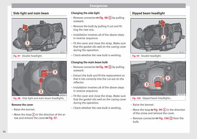
Emergencies
Side light and main beam
Fig. 97 Double headlight.
Fig. 98 Side light and main beam headlights.
Remove the cover
– Raise the bonnet.
– Move the loop 1 in the direction of the ar-row and remove the cover ››› Fig. 97.
Changing the side light
– Remove connector ››› Fig. 98 2 by pullingoutward.
– Remove the bulb by pulling it out and fit-ting the new one.
– Installation involves all of the above stepsin reverse sequence.
– Fit the cover and close the strap. Make surethat the gasket sits well on the casing coverduring the operation.
– Check whether the new bulb is working.
Changing the main beam bulb
– Remove connector ››› Fig. 98 3 by pullingoutward.
– Extract the bulb and fit the replacement sothat it sits correctly into the cut-out on thereflector.
– Installation involves all of the above stepsin reverse sequence.
– Fit the cover and close the strap. Make surethat the gasket sits well on the casing coverduring the operation.
– Check whether the new bulb is working.
Dipped beam headlight
Fig. 99 Double headlight.
Fig. 100 Dipped beam headlights.
– Raise the bonnet.
– Move the loop ››› Fig. 99 1 in the directionof the arrow and remove the cover.
– Remove connector ››› Fig. 100 2 from thebulb.
86

Fuses and bulbs
– Unclip the retainer spring ››› Fig. 100 3
pressing inwards to the right.
– Extract the bulb and fit the replacement sothat the lug on the base fits into the recesson the reflector.
– Fit the connector.
– Fit the cover and close the strap. Make surethat the gasket sits well on the casing coverduring the operation.
– Check whether the new bulb is working.
Turn signal light
Fig. 101 Turn signal light.
– Raise the bonnet.
– Turn the bulb holder ››› Fig. 101 1 to theleft and pull.
– Remove the bulb by pressing on the bulbholder and turning it anti-clockwise at thesame time.
– Installation involves all of the above stepsin reverse sequence.
Changing the AFS headlightbulbs
Position of the bulbs
Fig. 102 AFS headlight bulbs.
Turn signal
Xenon headlight (dipped beam/mainbeam)
A
B
Changing the xenon bulb
The procedure for changing the bulb is thesame on both sides of the vehicle.
WARNING
This type of bulb should be changed at a spe-cialised workshop.
Turn signal bulb
Fig. 103 Turn signal light.
– Raise the bonnet.
– Turn bulb holder ››› Fig. 103 A to the leftand pull.
– Remove the bulb by pressing on the bulbholder and turning it anti-clockwise at thesame time.
– Installation involves all of the above stepsin reverse sequence.
87
Tech
nica
l dat
aA
dvic
eO
pera
tion
Emer
genc
ies
Saf
ety
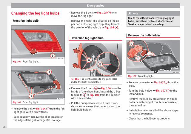
Emergencies
Changing the fog light bulbs
Front fog light bulb
Fig. 104 Front fog light.
Fig. 105 Front fog light.
– Remove the bolt ››› Fig. 104 1 from the foglight grille with a screwdriver.
– Subsequently, remove the clips located onthe edge of the grill with gentle leverage.
– Remove the 3 bolts ››› Fig. 105 2 to re-move the fog light.
– Remove the metal clip situated on the up-per part of the fog light by pulling towardsthe exterior of the vehicle ››› Fig. 105 3 .
FR version fog-light bulb
Fig. 106 Fog light: access to the connectorand to the light bulb holder.
– Remove the 4 bolts A ››› Fig. 106 from theinside of the wheel housing and the 2 bot-tom bolts B ››› Fig. 106 from the bumperwith a screwdriver.
– Pull the bumper to release it from its an-chorages to access the connector and thelight bulb holder.
Note
Due to the difficulty of accessing fog lightbulbs, have them replaced at a TechnicalService or specialised workshop.
Remove the bulb holder
Fig. 107 Front fog light.
– Remove connector ››› Fig. 107 1 from thebulb.
– Turn the bulb holder ››› Fig. 107 2 to theleft and pull.
– Remove the bulb by pressing on the bulbholder and turning it counter-clockwise atthe same time.
– Installation involves all of the above stepsin reverse sequence.
– Check that the bulb works properly.
88

Fuses and bulbs
Changing the tail light bulbs
Summary of LED tail lights3 Applies to the model: IBIZA/IBIZA SC
LED
● Brake lights
● Side lights
Bulbs
● Retro fog light
● Reverse lights
● Turn signal
Tail light summary3 Applies to the model: IBIZA ST
Tail lights on side panel Bulb lamps
● Brake lights
● Side lights
● Turn signal
Lights on the rear lid Bulb lamps
● Reverse lights
● Side lights
● Fog lights
Tail lights on side panel LED lamps
● Brake light (LED)
● Side light (LED)
● Turn signal
Lights on the rear lid LED lamps
● Reverse lights
● Side light (LED)
● Fog lights
Access to tail lights3 Applies to the model: IBIZA/IBIZA SC
Fig. 108 Access to tail lights.
● Open the rear lid.
● Turn the bolt in the direction of the arrow,by hand or with a screwdriver ››› Fig. 108.
● Remove the tail light, by pulling it out-wards.
Changing tail lights3 Applies to the model: IBIZA/IBIZA SC
Fig. 109 Changing the tail light bulbs
Fig. 110 Changing the tail light bulbs
● Remove the connector from housing A
››› Fig. 108. »
89
Tech
nica
l dat
aA
dvic
eO
pera
tion
Emer
genc
ies
Saf
ety

Emergencies
● Remove the bulb holder, separating it fromthe casing. To do this, press tabs B in thedirection of the arrows ››› Fig. 109.
● When the bulb holder has been removed,press in the direction of the arrow 1 and atthe same time, turn in the direction of the ar-row 2 ››› Fig. 110
Changing bulbs. LED lamps
Carry out the same operations as in lights fit-ted with bulbs.
If necessary, remove the socket, as if it werea bulb.
If the brake light and/or side light with LEDshave to be replaced, the tail light must be re-placed.
Changing the tail light bulbs (on theside panel)
3 Applies to the model: IBIZA ST
Fig. 111 Lights on the side.
Fig. 112 Removing the bulb holder.
Accessing the side light bulbs
● Open the rear lid.
● Look for a lid with a grill behind the sidelights.
● Remove the lid with a flat screwdriver, plac-ing it in notch A ››› Fig. 111.
Changing bulbs
● Remove the bulb holder by pressing thefastening clip B ››› Fig. 112 and pulling itoutwards.
● Replace the faulty bulb, rotating it to theleft and outwards.
● To refit follow the steps in reverse order,taking special care when fitting the bulbholder.
Changing bulbs. LED lamps
Carry out the same operations as in lights fit-ted with bulbs.
If necessary, remove the socket, as if it werea bulb.
If the brake light and/or side light with LEDshave to be replaced, the tail light must be re-placed.
90

Fuses and bulbs
Changing the tail light bulbs (on therear lid)
3 Applies to the model: IBIZA ST
Fig. 113 Lights on the boot.
Fig. 114 Removing the bulb holder.
Accessing the rear lid lights
● Open the rear lid.
● On the rear lid lining there is a lid behindeach light.
● Remove the lid with a flat screwdriver, plac-ing it in notch A ››› Fig. 113.
Changing bulbs
● Remove the bulb holder by pressing thefastening clips B ››› Fig. 114 and pullingoutwards.
● Replace the faulty bulb, rotating it to theleft and outwards.
● To refit follow the steps in reverse order,taking special care when fitting the bulbholder.
Changing bulbs. LED lamps
Carry out the same operations as in lights fit-ted with bulbs.
If necessary, remove the socket, as if it werea bulb.
If the brake light and/or side light with LEDshave to be replaced, the tail light must be re-placed.
Changing the side and interiorbulbs
Turn signals
Fig. 115 Turn signals.
– Press the turn signal to the left or to theright to remove the bulb.
– Remove the bulb holder from the turn sig-nal.
– Remove the failed bulb and replace with anew bulb.
– Insert the bulb holder in the turn signalguide until it clicks into place.
– First fit the turn signal in the opening in thechassis, fastening the tabs 1 ››› Fig. 115,and then fit in the bulb as shown by the ar-row 2 ››› Fig. 115.
91
Tech
nica
l dat
aA
dvic
eO
pera
tion
Emer
genc
ies
Saf
ety

Emergencies
Number plate light3 Applies to the model: IBIZA/IBIZA SC
– Insert the flat part of a screwdriver into thespecial slot and remove the bulb.
– Remove the bulb holder, by turning it untilit is free.
– Change the bulb.
– Replace the bulb holder, by turning it untilit fits fully.
– Fit the light into the space and press untilyou hear a “click”.
Number plate light3 Applies to the model: IBIZA ST
Fig. 116 Remove the number plate light.
– Insert the flat part of a screwdriver into thespecial slot and remove the number platelight from its moulding.
– Remove the connector and extract the bulb.After changing the bulb, fit the connectoragain.
– Place the light in its moulding, pressing theleft side. Once it is fitted into place, pressthe right side until you hear a “click”.
Additional brake light*
Given the difficulty involved in the replace-ment of this light it should be done by Tech-nical Services.
Interior light and front reading lights
Fig. 117 Front reading light.
To remove the glass
– Insert a fine screwdriver between the cas-ing and the glass ››› Fig. 117.
– Carefully remove the glass, levering it toavoid possible damage.
To replace the bulbs
– Pull the bulbs outwards.
– To remove the central bulb, hold and pressto one side.
Assembly
– Proceed in the reverse order, pressing gen-tly on the outer edge of the side light.
– First fit the glass with the fastening tabsover the frame of the switch. Next press thefront part until the two long tabs click onthe support.
92

Fuses and bulbs
Luggage compartment light*
Fig. 118 Boot light.
Fig. 119 Boot light.
– Extract the bulb by pressing on its insideedge -arrow- using the flat side of a screw-driver ››› Fig. 118.
– Press the bulb sideways and remove it fromits housing ››› Fig. 119.
93
Tech
nica
l dat
aA
dvic
eO
pera
tion
Emer
genc
ies
Saf
ety

Operation
Fig. 120 Dash panel.
94

Controls and displays
Operation
Controls and displays
General instrument panel
Door release lever
Light switch . . . . . . . . . . . . . . . . . . . . . . 123
Headlight range control* . . . . . . . . . . 125
Air vents
Lever for:
– Turn signals/main beam head-lights . . . . . . . . . . . . . . . . . . . . . . . . . . 125
– Cruise control* . . . . . . . . . . . . . . . . . 184
Instrument panel and warninglamps:
– Instruments . . . . . . . . . . . . . . . . . . . . 96
– Warning and indication lamps . . . 35
Steering wheel with horn and
– Driver airbag . . . . . . . . . . . . . . . . . . . 66
– On-board computer controls . . . . 25
– Controls for radio, telephone,navigation and speech dialoguesystem ››› Booklet Radio
– Paddle levers for tiptronic gear-shift (automatic gearbox) . . . . . . . 162
1
2
3
4
5
6
7
Steering and starter lock . . . . . . . . . . 153
Lever for:
– Windscreen wipers and washer . . 129
– Window washer-wiper system* . . 129
– Multi-function display control* . . 25
Infotainment system:
Depending on the equipment,glove compartment with: . . . . . . . . . 136
– CD player* and/or SD card*››› Booklet Radio
Passenger airbag* . . . . . . . . . . . . . . . . 14
Switches for:
– Heating and ventilation . . . . . . . . . 146
– Air conditioning* . . . . . . . . . . . . . . . 148
– Climatronic* . . . . . . . . . . . . . . . . . . . . 150
Depending on the equipment, but-tons for:
– SEAT Drive Profile . . . . . . . . . . . . . . . 185
– Park assist system . . . . . . . . . . . . . . 176
– Hazard warning lights . . . . . . . . . . 127
– Airbag off warning lamp* . . . . . . .68, 70
Depending on the equipment:
– USB/AUX-IN input . . . . . . . . . . . . . . 112
– Cigarette lighter/Power socket . . 138
Drink holder/Ashtray . . . . . . . . . . . . . 137
8
9
10
11
12
13
14
15
16
Controls in the centre console:
– Start-Stop operation button . . . . . 173
– Tyre pressure monitoring* . . . . . . . 104
– Heated rear window . . . . . . . . . . . . 128
– Heated seats* . . . . . . . . . . . . . . . . . . 134
– Central locking* . . . . . . . . . . . . . . . . 115
Handbrake lever . . . . . . . . . . . . . . . . . . 156
Gear lever
– Automatic* . . . . . . . . . . . . . . . . . . . . . 159
– Manual . . . . . . . . . . . . . . . . . . . . . . . . . 159
Storage space
Pedals . . . . . . . . . . . . . . . . . . . . . . . . . . . 61
Steering column control lever* . . . . 13
Bonnet release lever . . . . . . . . . . . . . . 203
Fuse housing . . . . . . . . . . . . . . . . . . . . . 81
Control for adjusting electric exteri-or mirrors* . . . . . . . . . . . . . . . . . . . . . . . 131
Electric window controls* . . . . . . . . . 120
Note
Some of the items of equipment listed hereare fitted only on certain model versions orare optional extras.
17
18
19
20
21
22
23
24
25
26
95
Tech
nica
l dat
aA
dvic
eO
pera
tion
Emer
genc
ies
Saf
ety

Operation
Instruments and warning/control lamps
Instruments
General instrument panel
Fig. 121 Instrument panel, on dash panel
The layout of the instruments depends uponthe model and the engine.
Rev counter (with the engine running, inhundreds of revolutions per minute)››› page 97.
The beginning of the red zone of the revcounter indicates the maximum speed inany gear after running-in and with the en-gine hot. However, it is advisable to
1
change up a gear or move the selectorlever to D (or lift your foot off the acceler-ator) before the needle reaches the redzone ››› .
Engine coolant temperature display››› page 99.
Displays on the screen ››› page 97.
Adjuster button and display››› page 99.
2
3
4
Speedometer.
Fuel gauge ››› page 100.
WARNING
Any distraction may lead to an accident, withthe risk of injury.
● Do not operate the instrument panel con-trols when driving.
5
6
96

Instruments and warning/control lamps
CAUTION
● To prevent damage to the engine, the revcounter needle should only remain in the redzone for a short period of time.
● When the engine is cold, avoid high revsand heavy acceleration and do not make theengine work hard.
For the sake of the environment
Changing up a gear in time reduces fuel con-sumption and noise.
Rev counter
The rev counter indicates the number of en-gine revolutions per minute ››› Fig. 121 1 .
Together with the gear-change indicator, therev counter offers you the possibility of usingthe engine of your vehicle at a suitablespeed.
The start of the red zone on the dial indicatesthe maximum engine speed which may beused briefly when the engine is warm and af-ter it has been run in properly. Before reach-ing this range, you should change to a highergear for vehicles with a manual gearbox or forautomatic gearboxes put the selector lever in“D” or take your foot off the accelerator ped-al.
We recommend that you avoid high revs andthat you follow the recommendations on thegear-change indicator. Consult the additionalinformation in ››› page 28, Gear-changeindicator.
CAUTION
Never allow the rev counter needle 1
››› Fig. 121 to go into the red zone on thescale for more than a very brief period, other-wise there is a risk of engine damage.
For the sake of the environment
Changing up a gear early will help you to savefuel and minimise emissions and enginenoise.
Indications on the display
A variety of information can be viewed on theinstrument panel display ››› Fig. 121 3 de-pending on the vehicle equipment:
● Bonnet, rear lid and doors open››› page 28.
● Information and warning texts.
● Mileage.
● Time.
● Navigation instructions.
● Outside temperature.
● Compass.
● Shift lever position ››› page 159.
● Recommended gear (manual gearbox)››› page 28.
● Multifunction display (MFD) and menuswith different setting options ››› page 25.
● Service interval display ››› page 33.
● Second speed display ››› page 25.
● Speed warning function ››› page 32.
● Start-Stop system status display››› page 173.
● Low consumption driving status (ECO)››› page 98
● Identifying letters on engine (MKB).
● Active cylinder management display(ACT®)* ››› page 167
Distance travelled
The odometer registers the total distancetravelled by the car.
The odometer (trip) shows the distancetravelled since the last odometer reset. Thelast digit of the trip recorder indicates distan-ces of 100 metres or one tenths of a mile.
● Briefly press the button ››› Fig. 121 4 to re-set the trip recorder to 0.
● Keep the button 4 pressed for about 3seconds and the previous value will be dis-played. »
97
Tech
nica
l dat
aA
dvic
eO
pera
tion
Emer
genc
ies
Saf
ety
Operation
Time
● To set the time, keep the button ››› Fig. 1214 pressed for more than 3 seconds to select
the hour or minute display.
● To continue setting the time, press the up-per or lower part of the button 4 . Hold but-ton down to scroll through the numbersquickly.
● Press the button 4 again in order to finishsetting the time.
The time can also be set via the key andSetup function button in the Easy Connect
system ››› page 107.
Compass
With the ignition on and the navigation sys-tem on, the cardinal point corresponding tothe direction of travel of the vehicle is dis-played on the instrument panel.
Selector lever position
The selected gear is displayed on the side ofthe selector lever and on the instrument pan-el display. In positions D and S, and with theTiptronic, the corresponding gear is also dis-played.
Recommended gear (manual gearbox)
The recommended gear in order to save fuelis displayed on the instrument panel whileyou are driving ››› page 28.
Second speed display (mph or km/h)
In addition to the speedometer, the speedcan also be displayed in a different unit ofmeasurement (in miles or in km per hour).
This option cannot be deactivated in modelsdestined for countries in which the secondspeed must always be visible.
The second speed display can be adjusted inthe Easy Connect system via the key andthe Setup function button ››› page 107.
Speed warning
When the speed setting is exceeded, this willbe indicated on the instrument panel display.This is very useful, for example when usingwinter tyres that are not designed for drivingat the maximum speed of the vehicle››› page 32.
The speed warning settings can be adjustedin the Easy Connect system via the keyand the Setup function button ››› page 107.
Start-Stop operating display
Updated information relating to the status isdisplayed on the instrument panel››› page 173.
Low consumption driving status (ECO)*
Depending on the equipment, when driving,the “ECO” display appears on the instrumentpanel when the vehicle is in low consump-
tion status due to active cylinder manage-ment (ACT®)* ››› page 30.
Identifying letters on engine (MKB)
Hold the button ››› Fig. 121 4 down for morethan 15 seconds to display the identifyingletters of the vehicle engine (MKB). To dothis, the ignition must be switched on andthe engine switched off.
WARNING
Observe the safety warnings ››› in Warningsymbols on page 101.
WARNING
Even though outside temperatures are abovefreezing, some roads and bridges may be icy.
● At outside temperatures above +4°C(+39°F), even when the “ice crystal symbol”is not visible, there may still be patches of iceon the road.
● Never rely on the outside temperature indi-cator!
Note
● Different versions of the instrument panelare available and therefore the versions andinstructions on the display may vary. In thecase of displays without warning or informa-tion texts, faults are indicated exclusively bythe warning lamps.
98

Instruments and warning/control lamps
● Depending on the equipment, some set-tings and instructions can also be carried outin the Easy Connect system.
● When several warnings are active at thesame time, the symbols are shown succes-sively for a few seconds and will stay on untilthe fault is rectified.
Odometer
Fig. 122 Instrument panel: odometer and re-set button.
The distance covered is displayed in “kilome-tres” or miles “m”. It is possible to changethe measurement units (kilometres“km”/miles “m”) in the radio/Easy Connect*.Please refer to the Easy Connect* InstructionsManual for more details.
Odometer/trip recorder
The odometer shows the total distance cov-ered by the vehicle.
The trip recorder shows the distance that hasbeen travelled since it was last reset. It isused to measure short trips. The last digit ofthe trip recorder indicates distances of 100metres or tenths of a mile.
The trip recorder can be set to zero by press-ing 0.0/SET ››› Fig. 122.
Fault display
If there is a fault in the instrument panel, theletters DEF will appear in the trip recorderdisplay. Have the fault repaired immediately,as far as is possible.
Coolant temperature gauge
For vehicles with no coolant temperaturegauge, a control lamp appears for highcoolant temperatures ››› page 207. Pleasenote ››› .
The coolant temperature gauge 2
››› Fig. 121 only works when the ignition isswitched on. In order to avoid engine dam-age, please read the following notes for thedifferent temperature ranges.
Engine cold
If only the diodes in the lower part of thescale light up, this indicates that the enginehas not yet reached operating temperature.Avoid high revs and heavy acceleration anddo not make the engine work hard.
Normal temperature
If in normal operations, the diodes light upuntil the central zone, it means that the en-gine has reached operating temperature. Athigh outside temperatures and when makingthe engine work hard, the diodes may contin-ue lighting up and reach the upper zone. Thisis no cause for concern, provided the controllamp does not light up on the instrumentpanel digital display.
Heat range
When the diodes light up in the upper area ofthe display and the control lamp appears on the instrument panel display, the coolanttemperature is excessive ››› page 207.
CAUTION
● To ensure a long useful life for the engine,avoid high revs, driving at high speed andmaking the engine work hard for approxi-mately the first 15 minutes when the engineis cold. The phase until the engine is warm al-so depends on the outside temperature. Ifnecessary, use the engine oil temperature*››› page 31 as a guide. »
99
Tech
nica
l dat
aA
dvic
eO
pera
tion
Emer
genc
ies
Saf
ety

Operation
● Additional lights and other accessories infront of the air inlet reduce the cooling effectof the coolant. At high outside temperaturesand high engine loads, there is a risk of theengine overheating.
● The front spoiler also ensures proper distri-bution of the cooling air when the vehicle ismoving. If the spoiler is damaged this can re-duce the cooling effect, which could causethe engine to overheat. Seek specialist assis-tance.
Fuel level
Fig. 123 Fuel gauge.
The display 6 ››› Fig. 121 only works whenthe ignition is switched on. When the displayreaches the reserve mark, the lower diodelights up in red and the control lamp ap-pears ››› page 96. When the fuel level is verylow, the lower diode flashes in red.
The distance to empty fuel level is displayedon the instrument panel 3 ››› Fig. 121.
You can consult the tank capacity of your ve-hicle in the ››› page 40 section.
CAUTION
Never run the fuel tank completely dry. An ir-regular fuel supply could cause misfiring. Inthis way the unburned fuel can reach the ex-haust system, which could cause the catalyticconverter to overheat resulting in damage.
Warning and indication lamps
Warning symbols
Read the additional information carefully››› page 35
There are red warning symbols (priority 1)and yellow warning symbols (priority 2).
Warning messages, Priority 1 (red)
If one of these faults occurs, the warninglamp will light up or flash and will be accom-panied by three audible warnings. This is adanger warning. Stop the vehicle and switchoff the engine. Check the fault and correct it.Obtain professional assistance if necessary.
If several priority 1 faults are detected at thesame time, the symbols will be displayed one
after the other for about 2 seconds at a timeand will continue until the fault is corrected.
No menus will be shown in the display for theduration of a priority 1 warning message.
Examples of priority 1 warning messages(red)
● Brake system symbol with the warningmessage STOP BRAKE FLUID INSTRUC-TION MANUAL or STOP BRAKE FAULT IN-STRUCTION MANUAL.
● Coolant symbol with the warning mes-sage STOP SEE COOLANT INSTRUCTIONMANUAL.
● Engine oil pressure symbol with thewarning message STOP ENGINE OILPRESSURE LOW! INSTRUCTION MANUAL.
Warning messages, Priority 2 (yellow)
If one of these faults occurs, the correspond-ing warning lamp lights up and is accompa-nied by an audible warning. Check the corre-sponding function as soon as possible al-though the vehicle may be used without risk.
If several priority 2 warning messages are de-tected at the same time, the symbols are dis-played one after the other for about 2 sec-onds at a time. After a set time, the informa-tion text will disappear and the symbol willbe shown as a reminder at the side of thedisplay.
100

Instruments and warning/control lamps
Priority 2 warning messages will not beshown until all Priority 1 warning messageshave been dealt with!
Examples of priority 2 warning reports (yel-low):*
● Fuel warning light with the information textPLEASE REFUEL.
WARNING
If the warning lamps and messages are ignor-ed, the vehicle may stall in traffic, or maycause accidents and severe injuries.
● Never ignore the warning lamps or textmessages.
● Stop the vehicle safely as soon as possible.
● Park the vehicle away from traffic and en-sure that there are no highly flammable ma-terials under the vehicle that could come intocontact with the exhaust system (e.g. drygrass, fuel).
● A faulty vehicle represents a risk of acci-dent for the driver and for other road users. Ifnecessary, switch on the hazard warninglamps and put out the warning triangle to ad-vise other drivers.
● Before opening the bonnet, switch off theengine and allow it to cool.
● In any vehicle, the engine compartment is ahazardous area and could cause severe inju-ries ››› page 201.
CAUTION
Failure to heed the control lamps and textmessages when they appear may result infaults in the vehicle.
Engine management*
This warning lamp monitors the engine man-agement system for petrol engines.
The warning lamp (Electronic Power Con-trol) lights up when the ignition is switchedon while system operation is being verified. Itshould go out once the engine is started.
If there is a fault in the electronic enginemanagement system while you are driving,this warning lamp will light up. Stop the vehi-cle and seek technical assistance.
Engine pre-heating/fault system*
The warning lamp lights up to show that theglow plugs are preheating the diesel engine.
The control lamp lights up
If the control lamp lights up when the en-gine is started it means that the glow plugsare preheating. When the warning lamp goesoff, the engine should be started straightaway.
Control lamp flashes
If a fault develops in the engine managementsystem while you are driving, the glow plugsystem lamp will flash . Take the vehicle toa specialised workshop as soon as possibleand have the engine checked.
Accumulation of soot in the diesel en-gine particulate filter*
If the control lamp lights up you shouldhelp the filter clean itself by driving in the ap-propriate manner.
To do this, drive about 15 minutes in fourthor fifth gear (automatic gearbox: S gearrange) at a minimum speed of 60 km/h(37 mph), with the engine running at approxi-mately 2,000 rpm. In this way, the soot buildup in the filter is burned. When cleaning issuccessful, the control lamp turns off.
If the lamp does not turn off, or the threelamps turn on (particulate filter , fault inthe emission control system and glowplugs ), drive the vehicle to a specialisedworkshop and have the fault repaired at theearliest opportunity. »
101
Tech
nica
l dat
aA
dvic
eO
pera
tion
Emer
genc
ies
Saf
ety

Operation
WARNING
● Always drive according to the road weatherconditions, the terrain and traffic. Driving rec-ommendations should never lead to illegalmanoeuvres in surrounding traffic.
● The diesel engine particulate filter mayreach extremely high temperatures; in thiscase the vehicle should be parked so that itdoes not enter into contact with highly flam-mable materials underneath the vehicle. Oth-erwise there is a risk of fire.
Engine oil pressure
If this warning lamp is red it indicatesthat the engine oil pressure is too low.
If this warning symbol starts to flash, and isaccompanied by three audible warnings,switch off the engine and check the oil level.If necessary, add more oil ››› page 206.
If the warning lamp flashes although the oillevel is correct, stop driving. Do not even runthe engine at idle speed! Obtain technical as-sistance.
Checking the oil level
If the warning lamp is yellow the engineoil level should be checked as soon as possi-ble. Top up the oil ››› page 206 at the nextopportunity.
Oil level sensor faulty*
If the yellow warning lamp flashes, takethe vehicle to a specialised workshop to havethe oil level sensor checked. Until then it isadvisable to check the oil level every timeyou refuel.
Lamp fault*
The warning lamp lights up when there isa fault on the turn signals, headlights, sidelights and fog lights.
Windscreen washer fluid*
This warning lamp lights up to indicate thatthe windscreen washer level is very low.
This serves as a reminder to fill up the reser-voir at the earliest opportunity ››› page 209.
Rear fog light*
The warning lamp lights up when the rearfog light is switched on. For further informa-tion see ››› page 123.
Anti-lock brake system (ABS)*
The control lamp lights up for a few sec-onds when the ignition is switched on. Itgoes out again after the system has runthrough an automatic test sequence.
There is a fault in the ABS if:
● The control lamp does not light up whenthe ignition is switched on.
● The control lamp does not go out again af-ter a few seconds.
● The control lamp lights up when the vehicleis moving.
The vehicle can still be braked in the normalway, without the ABS function. Take the vehi-cle to a specialised workshop as soon aspossible. For further information on the ABSsee the ››› page 171.
If there is a fault in the ABS, the ESC* and thetyre pressure control lamp will also light up.
Brake system fault
If the ABS warning lamp lights up togetherwith the brake warning lamp , there is afault in the ABS function and in the brakesystem ››› .
102

Instruments and warning/control lamps
WARNING
● Before opening the bonnet, read and ob-serve the warnings ››› page 201, Working inthe engine compartment.
● If the brake system warning lamp shouldlight up together with the ABS warning lamp, stop the vehicle immediately and checkthe brake fluid level in the reservoir››› page 208, Brake fluid. If the brake fluidlevel has dropped below the “MIN” mark youmust not drive on. Risk of accident. Obtaintechnical assistance.
● If the brake fluid level is correct, the fault inthe brake system may have been caused by afailure of the ABS system. This could causethe rear wheels to lock quickly when youbrake. This could cause the rear to breakaway. Risk of skidding. Stop the vehicle andseek technical assistance.
Differential lock fault (EDS)*
The EDL operates along with the ABS in vehi-cles equipped with Electronic Stability Con-trol (ESC)*.
A malfunction in the EDL is indicated by theABS control lamp . Take the vehicle to aspecialised workshop as soon as possible.For further information on the EDL see››› page 170, Electronic differential lock(EDS)*.
Traction control system (ASR)* /
The traction control system prevents the driv-en wheels from spinning when the vehicle isaccelerating.
There are two control lamps for the tractioncontrol system: and . Both control lampslight up together when the ignition is switch-ed on and should turn off after approximately2 seconds. This is the time taken for the func-tion check.
The lamp has the following function:
● It flashes when the ASR is working if the ve-hicle is moving.
If the system is deactivated or if it has anyfault, the warning lamp will remain lit. Thewarning lamp will also light up if a faultshould occur in the ABS because the ASR op-erates in conjunction with the ABS. For fur-ther information, see ››› page 172.
The lamp provides information about thedisconnection status of the system:
● It stays lit when the ASR is disconnectedvia Easy Connect.
By means of Easy Connect, the ASR functionis reactivated and the warning lamp switchedoff.
Electronic Stability Control (ESC)*/
There are two control lamps for the electronicstability control. The lamp provides infor-mation concerning function and disconnec-tion status.
Both control lamps light up together whenthe ignition is switched on and should turnoff after approximately 2 seconds. This is thetime taken for the function check.
This programme includes the ABS, EDL andASR. It also includes emergency braking as-sistance (BAS).
The control lamp has the following func-tions:
● It flashes whilst driving when the ASR/ESCis activated.
● It will light up if there is a fault in the ESC.
● As the ESC operates in conjunction with theABS, the ESC light will also come on if a faultshould occur in the ABS.
If the ESC control lamp lights up and stayson after the engine is started, this may meanthat the control system has temporarilyswitched off the ESC. In this case the ESC canbe reactivated by switching the ignition offand then on again. If the control lamp goesout, this means the system is fully functional. »
103
Tech
nica
l dat
aA
dvic
eO
pera
tion
Emer
genc
ies
Saf
ety

Operation
The lamp provides information about thedisconnection status of the system:
● It stays lit when the ASR is disconnected onpressing the switch or if we select ESCSport mode, only by means of Easy Connect.
Brake system*
Situations in which the warning lamp lightsup
● the brake fluid level is too low››› page 208.
● there is a fault in the brake system.
This warning lamp can light up together withthe ABS system warning lamp.
WARNING
● If the brake warning lamp does not go outor if it lights up when driving, the brake fluidlevel in the reservoir is too low so there is arisk of an accident ››› page 208, Brake fluid.Stop the vehicle and do not drive on. Obtaintechnical assistance.
● If the brake warning lamp lights up to-gether with the ABS lamp this could bedue to an ABS fault. This could cause the rearwheels to lock quickly when you brake. Thiscould cause the rear to break away. Risk ofskidding. Stop the vehicle and seek technicalassistance.
Cruise speed (cruise control system)*
The warning lamp comes on when thecruise control system is switched on. For fur-ther information on the cruise control systemplease see ››› page 34.
Tyre pressure
Fig. 124 Centre console: tyre monitoring sys-tem button.
The tyre monitoring lamp* compares wheelrevolutions and with it, using the ESC, thewheel diameter of each wheel. If the diame-ter of a wheel changes, the tyre control lamp lights up. The wheel diameter changeswhen:
● Tyre pressure is insufficient.
● The tyre structure is damaged.
● The vehicle is unbalanced because of aload.
● The wheels of one axle are under morepressure (for example, driving with a trailer oron steep slopes).
● The vehicle is fitted with snow chains.
● The temporary spare wheel is fitted.
● The wheel on one axle is changed.
Tyre pressure adjustment
On adjusting tyre pressure or changing oneor more wheels, the ››› Fig. 124 button mustbe kept pressed down, with the ignition on,until an acoustic signal is heard.
Store the new tyre pressure in the Easy Con-nect system with the button and the func-tion button Setup ››› page 24.
If the wheels are under excessive load (for ex-ample, driving with a trailer or heavy load),the tyre pressure must be increased to therecommended value for a full load (see thesticker on the inside of the fuel flap). If thetyre monitor system button is pressed down,the new tyre pressures are confirmed.
The tyre pressure control lamp lights up
If the tyre pressure of a wheel is much lowerthan the value set by the driver, then the tyrepressure control lamp ››› will light up.
104

Instruments and warning/control lamps
WARNING
● When the tyre pressure control lamp lightsup, reduce speed immediately and avoid anysudden turning or braking manoeuvre. Stopwhen possible, and check the tyre pressureand status.
● The driver is responsible for maintainingcorrect tyre pressures. For this reason, tyrepressure must be regularly checked.
● Under certain circumstances (e.g. whendriving in a sporty manner, in winter condi-tions or on a dirt track) the tyre control lampmay light up belatedly or may function incor-rectly.
Note
If the battery is disconnected, the yellowwarning lamp lights up after turning theignition on. This should turn off after a briefjourney.
Speed selector lever lock*
The brake pedal must be depressed whenthis warning lamp lights up. This is necessarywhen the automatic gearbox* selector leveris moved out of the positions P or N.
Fuel Reserve/Level
It lights up when only 7 litres of fuel remainin the tank, and an acoustic signal* alsosounds. It reminds you to fuel up the fueltank as soon as possible ››› page 199.
Main beam headlights
The control lamp lights up when the mainbeams are on or when the headlight flasheris operated.
For further information see ››› page 125.
Electromechanical steering*
The control lamp should light up for a fewseconds when the ignition is switched on. Itshould go out once the engine is started.
For further information on steering see››› page 152.
It lights up red
The electromechani-cal steering is dam-aged.
Have the steering checked im-mediately by a specialised work-shop.
It lights up yellow
Electromechanicalsteering operationis limited.
Have the steering checked im-mediately by a specialised work-shop.If the yellow warning lamp doesnot light up again after the en-gine is restarted and the vehiclehas travelled a short distance,you do not need to take it to aspecialised workshop.
The 12-volt batterywas disconnectedand has been recon-nected.
Take the vehicle for a short runat 15-20 km/h (9-12 mph).
It flashes yellow
The steering columnis tight.
Turn the wheel a little to bothsides.
The steering columndoes not unlock orlock.
Remove the key from the ignitionand switch the ignition back on.If necessary, check the messag-es displayed on the instrumentpanel display.Do not drive on if the steeringcolumn remains locked after theignition has been switched on.Seek specialist assistance.
WARNING
If the warning lamps and the correspondingmessages are ignored when they light up, thevehicle may stall in traffic and cause acci-dents and severe injuries. »
105
Tech
nica
l dat
aA
dvic
eO
pera
tion
Emer
genc
ies
Saf
ety

Operation
● Never ignore the warning lamps or messag-es.
● Stop the vehicle at the next opportunityand in a safe place.
Note
Failure to heed the control lamps and corre-sponding text messages when they light upmay result in damage to the vehicle.
Emission control system*
Control lamp flashes:
When there is misfiring that can damage thecatalytic converter. Reduce speed and drivecarefully to the nearest specialised workshopto have the engine checked.
The control lamp lights up:
If a fault has developed during driving whichhas reduced the quality of the exhaust gas(e.g. lambda probe fault). Reduce speed anddrive carefully to the nearest specialisedworkshop to have the engine checked.
Coolant Level*/Temperature
There is a fault if:
● The warning symbol does not go out againafter a few seconds.
● The control lamp lights up or flashes whilethe vehicle is moving, and three acousticwarning signals ››› are emitted.
This means that either the coolant level is toolow or the coolant temperature is too high.
Coolant temperature too high
If the control lamp comes on, stop the vehi-cle, turn off the engine and wait for it to cooldown. Check the coolant level.
If the coolant level is correct, the overheatingmay be caused by a malfunction of the radia-tor fan. Check the radiator fan fuse and haveit replaced if necessary ››› page 81.
If the control lamp lights up again after driv-ing on for a short distance, stop the vehicleand switch the engine off. Contact a Techni-cal Service or a specialised workshop.
Coolant level too low
If the control lamp comes on , stop the vehi-cle, turn off the engine and wait for it to cooldown. First check the coolant level. If the lev-el of the coolant is below the “MIN” mark,top up with coolant liquid ››› .
WARNING
● If your vehicle is immobilised for technicalreasons, move it to a safe distance from traf-fic. Turn the engine off, turn the hazard lightson and place the warning triangle.
● Never open the bonnet if you can see orhear steam or coolant escaping from the en-gine compartment. Risk of scalding. Wait un-til you can no longer see or hear escapingsteam or coolant.
● The engine compartment is a dangerousarea. Before carrying out any work in the en-gine compartment, switch off the engine andallow it to cool down. Always note the corre-sponding warnings ››› page 201.
Alternator
This control lamp signals a fault in the alter-nator.
The control lamp lights up when the igni-tion is switched on. It should go out when theengine has started running.
If the control lamp lights up while driving,the alternator is no longer charging the bat-tery. You should immediately drive to thenearest specialised workshop.
You should avoid using electrical equipmentthat is not absolutely necessary because thiswill drain the battery.
Turn signals
Depending on which turn signal is operating,either the left or right turn signal lampflashes. Both control lamps will flash at the
106

Introduction to the Easy Connect system*
same time when the hazard warning lightsare switched on.
If any of both turn signals fails, the warninglamp will start flashing twice faster than nor-mal.
For further information on the turn signals,please see ››› page 125.
Electronic immobiliser “SAFE”*
This warning lamp flashes if an unauthorisedkey is used.
Inside the key there is a chip that deactivatesthe electronic immobiliser automaticallywhen the key is inserted into the ignition.The electronic immobiliser will be activatedagain automatically as soon as you pull thekey out of the ignition lock.
If the following message* is shown on the in-strument panel display: SAFE, the vehiclecannot be started.
The engine can, however, be started if theappropriate coded SEAT genuine key is used.
Note
The vehicle cannot operate properly if you donot have a genuine SEAT key.
Introduction to the EasyConnect system*
System settings (CAR)*
CAR menu (Setup)
Read the additional information carefully››› page 24
To select the settings menus, press the EasyConnect button and the Setup functionbutton.
The actual number of menus available andthe name of the various options in these me-nus will depend on the vehicle’s electronicsand equipment.
Pressing the menu button will always takeyou to the last menu used.
When the function button check box is activa-ted , the function is active.
Pressing the menu button will always takeyou to the last menu used.
Any changes made using the settings menusare automatically saved on closing those me-nus.
Function buttons in thevehicle’s settingsmenu
Page
ESC system ››› page 169
Tyres ››› page 104
Driver assistance ››› table on page 24
Parking and manoeuvring ››› page 176
Vehicle lights ››› table on page 24
Rear vision mirrors and wind-screen wipers
››› table on page 24
Opening and closing ››› table on page 24
Multifunction display ››› table on page 24
Date and time ››› table on page 24
Units ››› table on page 24
Service ››› page 97
Factory settings ››› table on page 24
WARNING
Any distraction may lead to an accident, withthe risk of injury. Operating the Easy Connectsystem while driving could distract you fromtraffic.
107
Tech
nica
l dat
aA
dvic
eO
pera
tion
Emer
genc
ies
Saf
ety

Operation
Communications and multi-media
Steering wheel controls*
General information
The vehicle includes a multifunction modulefrom where it is possible to control the audio,telephone and radio/navigation functionswithout needing to distract the driver.
There are two versions of the multifunctionmodule:
● Audio version, to control the available au-dio functions from the steering wheel (Radio,audio CD, MP3 CD, iPod®1), USB1)).
● Audio + telephone versions o control theavailable audio functions from the steeringwheel (Radio, audio CD, MP3 CD, iPod®1),USB1), SD1)) and the Bluetooth system.
1) Depending on the vehicle equipment.108
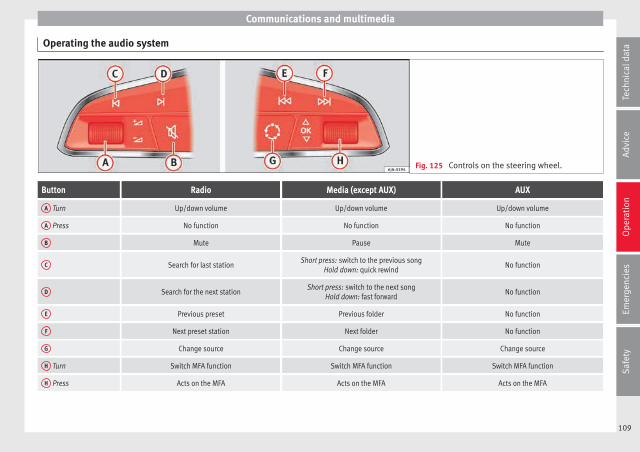
Communications and multimedia
Operating the audio system
Fig. 125 Controls on the steering wheel.
Button Radio Media (except AUX) AUX
A Turn Up/down volume Up/down volume Up/down volume
A Press No function No function No function
B Mute Pause Mute
C Search for last stationShort press: switch to the previous song
Hold down: quick rewindNo function
D Search for the next stationShort press: switch to the next song
Hold down: fast forwardNo function
E Previous preset Previous folder No function
F Next preset station Next folder No function
G Change source Change source Change source
H Turn Switch MFA function Switch MFA function Switch MFA function
H Press Acts on the MFA Acts on the MFA Acts on the MFA
109
Tech
nica
l dat
aA
dvic
eO
pera
tion
Emer
genc
ies
Saf
ety

Operation
Operating the audio system + telephone
Fig. 126 Controls on the steering wheel.
Button Radio Media (except AUX) AUX Telephonea) Navigationa)
A Turn Up/down volume Up/down volume Up/down volume Up/down volume Up/down volume
A Press Mute Pause Mute Mute Mute
B
Short press: access to the tele-phone menu on the dash pan-
ela).Hold down: rediala)
Short press: access to the tele-phone menu on the dash pan-
ela).Hold down: rediala)
Short press: access to the tele-phone menu on the dash pan-
ela).Hold down: rediala)
Short press: answer/hang upcalls, enable/open the tele-
phone menu.Hold down: reject an incoming
call/switch to private/redialmode
Short press: access to the tele-phone menu on the dash pan-
ela).Hold down: rediala)
C Search for last stationShort press: switch to the pre-
vious songHold down: quick rewind
No function No functionb) Radio/media functionality (ex-cept AUX )
D Search for the next stationShort press: switch to the next
songHold down: fast forward
No function No functionb) Radio/media functionality (ex-cept AUX )
EChange menu on instrument
panelChange menu on instrument
panelChange menu on instrument
panelChange menu on instrument
panelChange menu on instrument
panel
110

Communications and multimedia
Button Radio Media (except AUX) AUX Telephonea) Navigationa)
FChange menu on instrument
panelChange menu on instrument
panelChange menu on instrument
panelChange menu on instrument
panelChange menu on instrument
panel
G Enable/disable voice controla) Enable/disable voice controla) Enable/disable voice controla) No functionb) Enable/disable voice control
H Turn Next/previous preset stationc) Next/previous songc)Acts upon the dash panel
menu depending on where it islocated
Acts upon the dash panelmenu depending on where it
is located
Acts upon the dash panelmenu depending on where it
is located
H Press
Acts on the MFA or confirmsthe menu option of the dash
panel depending on the menuoption
Acts on the MFA or confirmsthe menu option of the dash
panel depending on the menuoption
Acts on the MFA or confirmsthe menu option of the dash
panel depending on the menuoption
Acts on the MFA or confirmsthe menu option of the dash
panel depending on the menuoption
Acts on the MFA or confirmsthe menu option of the dash
panel depending on the menuoption
a) According to the vehicle's equipment package.b) When a call is being made, radio/media functionality (except AUX).c) Only if the dash panel is in audio menu.
111
Tech
nica
l dat
aA
dvic
eO
pera
tion
Emer
genc
ies
Saf
ety

Operation
Multimedia
USB/AUX-IN input
Fig. 127 USB/AUX-IN input.
Depending on the features and the country,the vehicle may have a USB/AUX-IN connec-tion.
The USB/AUX-IN input is located above thestorage compartment in the front centre con-sole ››› Fig. 127.
The operating description is located in the re-spective Instruction Manuals of the audiosystem or the navigation system.
Opening and closing
Central locking system
Description
Read the additional information carefully››› page 9.
The central locking system enables you tolock and unlock all doors and the rear lid byjust pushing the button.
Central locking can be activated by using anyof the following options:
● the key, by inserting it into the driver doorcylinder and rotating it in the opening direc-tion. Depending on the vehicle version, ei-ther all doors will be unlocked or only thedriver door will be unlocked. All doors will belocked on locking the vehicle using the key.
● the interior central lock button››› page 115.
● the radio frequency remote control, usingthe buttons on the key ››› page 117.
Various functions are available to improvethe vehicle safety:
Locking system “Safe*”
Selective* unlocking system
Self-locking system to prevent involunta-ry unlocking
–
–
–
Automatic speed dependent locking andunlocking system*
Emergency unlocking system
Unlocking the vehicle*
Press button ››› Fig. 131 on remotecontrol to unlock all the doors and rearlid.
Locking the vehicle*
Press button ››› Fig. 131 on the re-mote control to lock all doors and therear lid or turn the key in the door to lockall doors and the rear lid.
WARNING
● Locking from the outside carelessly or with-out good visibility may lead to bruising, par-ticularly in the case of children.
● When locking a vehicle, never leave chil-dren unaccompanied inside, as from the out-side it will be difficult to provide assistance ifrequired.
● Having the doors locked prevents intrudersfrom getting in, for example when stopped ata traffic light.
Note
For anti-theft security, only the driver door isfitted with a lock cylinder.
–
–
–
–
112

Opening and closing
“Safe” security system**
This is an anti-theft device which consists ofa double lock for the door locks and a deacti-vation function for the boot in order to pre-vent forced entry.
Activation
The “safe” system is activated when the vehi-cle is locked using the key or the remote con-trol.
To activate it with the key, rotate once it is in-serted in the door lock cylinder in the lockingdirection.
To activate the system using the remote con-trol, press the lock button once on the re-mote.
Once this system is activated, opening doorsfrom the outside and the inside is not possi-ble. The rear lid can not be opened. The cen-tral lock button does not work.
When the ignition is switched off, the instru-ment panel display indicates that the “Safe”system is on.
Deactivation
Rotate the key inserted in the lock cylindertwice towards the locking direction.
To activate the system using the remote con-trol, press the lock button on the remotetwice in less than five seconds.
On deactivating the “Safe” system, the alarmvolumetric sensor is also deactivated.
With the “Safe” switched off, doors can beopened from the interior but not from the ex-terior.
See “Selective unlocking system*”
“Safe” status
On the driver door, there is warning lamp visi-ble from outside the vehicle through the win-dow which shows the “Safe” system status.
We will know that “Safe” system is activatedby the flashing warning lamp. The indicatorwill flash on all vehicles, fitted and nor fittedwith an alarm, until they unlock.
Remember:
Safe activated with or without an alarm:warning lamp flashes continuously.
Safe deactivated without an alarm: the warn-ing lamp stays off.
Safe deactivated with an alarm: the warninglamp stays off.
WARNING
No one should remain inside the vehicle if the“Safe” system is activated because openingthe doors will not be possible in the event ofan emergency neither from the inside nor theoutside and help from the outside is made
difficult. Danger of death. Passengers couldbecome trapped inside in case of emergency.
Selective unlocking system*
This system allows to unlock either just thedriver door or all the vehicle.
Driver door unlock button
Unlock once. Use either the key or the remotecontrol.
Once the key is inserted in the lock cylinder,rotate once in the unlock direction. The driverdoor will remain without “Safe” and un-locked. In vehicles fitted with an alarm, seethe Anti-theft Alarm section ››› page 118.
Using the remote control, press the unlockbutton on the remote once. The “Safe”system for all the vehicle is deactivated, onlythe driver door is unlocked and both thealarm and the warning lamp are also turnedoff.
Unlocking all doors and the luggage com-partment
The unlock button on the remote controlmust be pressed twice so that all doorsand the luggage compartment can beopened.
Press twice within 5 seconds to deactivatethe “Safe” system for all vehicle, to unlock all »
113
Tech
nica
l dat
aA
dvic
eO
pera
tion
Emer
genc
ies
Saf
ety

Operation
doors and to use the luggage compartment.The warning lamp and the alarm (only vehi-cles fitted with one) are turned off.
Unlocking the luggage compartment
See ››› page 9.
Activating the selective unlocking system*
With the door open, insert a key into the startcylinder and start the ignition. Insert the oth-er key into the driver door lock and turn in theopening direction for at least 3 seconds. Theturn signals will flash twice.
Deactivating the selective unlocking system*
With the door open, insert a key into the startcylinder and start the ignition. Insert the oth-er key into the driver door lock and turn in thelocking direction for at least 3 seconds. Theturn signals will flash once.
Self-locking system to prevent invol-untary unlocking
It is an anti-theft system and prevents the un-intentional unlocking of the vehicle.
If the vehicle is unlocked and none of thedoors (including the boot) are opened within30 seconds, it re-locks automatically.
Automatic speed-dependent lockingand unlocking system*
This is a safety system which prevents accessto the vehicle from the outside when it is run-ning (e.g. when stopped at a traffic light).
Locking
The doors will lock automatically if the speedof 15 km/h (9 mph) is exceeded. The rear lidwill lock automatically if the speed of 6 km/h(4 mph) is exceeded.
If the vehicle is stopped and any of its doorsopen, when starting again and exceeding thementioned speed, all doors will lock again.
Unlocking
On withdrawing the ignition key, the vehiclewill returns to its status prior to self-locking.
Each door can be unlocked and opened inde-pendently from the inside (for example, whena passenger gets out). To do it, simply oper-ate the lever inside the door.
Activating the system*
With the ignition on, press the locking key onthe central locking system within 3 to 10 sec-onds.
Deactivating the system*
With the ignition on, press the unlocking keyon the central locking system within 3 to 10seconds.
In both cases, if the operation has been car-ried out correctly, the locking lamp will flash ››› Fig. 128.
WARNING
The door handles must not be operated whenthe vehicle is running: the door would open.
Note
If the airbags are triggered during an acci-dent, the vehicle is unlocked, except for theluggage compartment. It is possible to lockthe vehicle from inside with the central lock-ing, after turning the ignition off and back onagain.
114

Opening and closing
Central lock button*
Fig. 128 Central lock button.
Read the additional information carefully››› page 9
The central lock button allows you to lock andunlock the vehicle from the inside.
The central lock button also works with theignition switched off, except when the “safe”system is activated.
Please note the following if you lock your ve-hicle with the central lock button:
● Locking the doors and rear lid prevents ac-cess from the outside (for safety reasons, e.g.when stopped at a traffic light).
● The driver door cannot be locked while it isopen. This avoids the user from forgetting hiskey inside the vehicle.
● All doors can be unlocked separately frominside the vehicle. Do this by pulling the doorrelease lever once.
WARNING
● If the vehicle is locked, children and disa-bled people may be trapped inside it.
● Repeated operation of central locking willprevent the central lock button from workingfor a few seconds. Then, it can only be un-locked in case it has been previously locked.After few seconds, the central locking be-comes operative again.
● The central lock button is not operativewhen the vehicle is locked from the outside(with the remote control or the key).
Note
● Vehicle locked, button.
● Vehicle unlocked, button.
Childproof lock3 Valid for vehicles: 5-door versions
Fig. 129 Childproof lock on the left hand sidedoor.
The childproof lock prevents the rear doorsfrom being opened from the inside. This sys-tem prevents minors from opening a door ac-cidentally while the vehicle is running.
This function is independent of the vehicleelectronic opening and locking systems. Itonly affects rear doors. It can only be activa-ted and deactivated manually, as describedbelow:
Activating the childproof lock
– Unlock the vehicle and open the door inwhich you wish to activate the childprooflock.
– With the door open, rotate the groove inthe door using the ignition key, anti-clock-wise for the left-hand side doors ››› Fig. 129 »
115
Tech
nica
l dat
aA
dvic
eO
pera
tion
Emer
genc
ies
Saf
ety

Operation
and clockwise for the right-hand sidedoors.
Deactivating the childproof lock
– Unlock the vehicle and open the doorwhose childproof lock you want to deacti-vate.
– With the door open, rotate the groove inthe door using the ignition key, anti-clock-wise for the right-hand side doors, andclockwise for the left-hand side doors››› Fig. 129.
Once the childproof lock is activated, thedoor can only be opened from the outside.The childproof lock can be activated or deac-tivated by inserting the key in the groovewhen the door is open, as described above.
Keys
Set of keys
Fig. 130 Set of keys.
The set of keys may consists of the following,depending on the version of your vehicle:
● a remote control key ››› Fig. 130 A
● a key without remote control B ,
● a plastic key tab* C .
or
● two keys without remote control B
● a plastic key tab* C .
Duplicate keys
If you need a replacement key, go to a Techni-cal Service with your vehicle identificationnumber.
WARNING
● An incorrect use of the keys can cause seri-ous injuries.
● Never leave children or disabled persons inthe vehicle. In case of emergency, they maynot be able to leave the vehicle or manage ontheir own.
● An uncontrolled use of the key could startthe engine or activate any electric equipment(e.g. electric windows), causing risk of acci-dent. The doors can be locked using the re-mote control key. This could become an ob-stacle for assistance in an emergency situa-tion.
● Never forget the keys inside the vehicle. Anunauthorised use of your vehicle could resultin injury, damage or theft. Always take thekey with you when you leave the vehicle.
● Never remove the key from the ignition ifthe vehicle is in motion. Otherwise, the steer-ing could suddenly block and it would be im-possible to steer the vehicle.
CAUTION
There are electronic components in the re-mote control key. Avoid wetting and hittingthe keys.
116
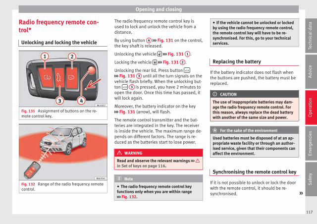
Opening and closing
Radio frequency remote con-trol*
Unlocking and locking the vehicle
Fig. 131 Assignment of buttons on the re-mote control key.
Fig. 132 Range of the radio frequency remotecontrol.
The radio frequency remote control key isused to lock and unlock the vehicle from adistance.
By using button 4 ››› Fig. 131 on the control,the key shaft is released.
Unlocking the vehicle ››› Fig. 131 1 .
Locking the vehicle ››› Fig. 131 2 .
Unlocking the rear lid. Press button ››› Fig. 131 3 until all the turn signals on thevehicle flash briefly. When the unlocking but-ton 3 is pressed, you have 2 minutes toopen the door. Once this time has passed, itwill lock again.
Moreover, the battery indicator on the key››› Fig. 131 (arrow), will flash.
The remote control transmitter and the bat-teries are integrated in the key. The receiveris inside the vehicle. The maximum range de-pends on different factors. The range is re-duced as the batteries start to lose power.
WARNING
Read and observe the relevant warnings ››› in Set of keys on page 116.
Note
● The radio frequency remote control keyfunctions only when you are within range››› Fig. 132.
● If the vehicle cannot be unlocked or lockedby using the radio frequency remote control,the remote control key will have to be re-synchronised. For this, go to your technicalservices.
Replacing the battery
If the battery indicator does not flash whenthe buttons are pushed, the battery must bereplaced.
CAUTION
The use of inappropriate batteries may dam-age the radio frequency remote control. Forthis reason, always replace the dead batterywith another of the same size and power.
For the sake of the environment
Used batteries must be disposed of at an ap-propriate waste facility or through an author-ised service, given that their components canaffect the environment.
Synchronising the remote control key
If it is not possible to unlock or lock the doorwith the remote control, it should be re-synchronised. »
117
Tech
nica
l dat
aA
dvic
eO
pera
tion
Emer
genc
ies
Saf
ety

Operation
While the vehicle is open:
– Press the button 2 ››› Fig. 131 on theremote control.
– Then close the vehicle using the key shaftwithin one minute.
While the vehicle is closed:
– Press the button 1 ››› Fig. 131 on theremote control.
– Then close the vehicle using the key shaftwithin one minute.
It is possible that the vehicle could no longerbe opened and closed with the remote con-trol if the button is repeatedly pressedoutside of the effective range of the radio fre-quency remote control. The remote controlkey will have to be resynchronised.
Spare remote control keys are available atyour Technical Service, where they must bematched to the locking system.
Up to five remote control keys can be used.
Anti-theft alarm*
Description of anti-theft alarm sys-tem*
The anti-theft alarm makes it more difficult tobreak into the vehicle or steal it. The systemwill initiate acoustic and optical warning sig-nals when your vehicle is tried to be forced.
The anti-theft alarm system is automaticallyswitched on when locking the vehicle. Thesystem is immediately activated and the turnsignal light located on the driver door willflash along with the turn signals, indicatingthat the alarm and the locking security sys-tem (double lock) have been turned on.
If any of the doors or the bonnet are open,they will not be included in the protectionzones of the vehicle when the alarm is con-nected. If the door or the bonnet are subse-quently closed, they will be automatically in-cluded in the protection areas of the vehicleand the turn signals will flash accordinglywhen the doors close.
● The turn signal light will flash twice onopening and deactivating the alarm.
● The turn signal light will flash once on clos-ing and activating the alarm.
When does the system trigger an alarm?
The system triggers an alarm, if the followingunauthorised actions are carried out whenthe vehicle is locked:
● Mechanical opening of the vehicle with thevehicle key without switching on the ignitionin the next 15 seconds (in certain markets,such as the Netherlands, the alarm is activa-ted immediately).
● A door is opened.
● Opening the bonnet.
● The rear lid is opened.
● Ignition switched on with a non-validatedkey.
● Movements in the driving compartment(vehicles with a volume sensor).
● Towing of the vehicle1).
● Vehicle tilt angle1).
● Undue manipulation of the alarm.
● Battery handling.
In this case, the acoustic signals will go offand the turn signal will flash for approximate-ly 30 seconds. This cycle may be repeated upto 10 times depending on the country.
1) With vehicles fitted with a tow-away protection118

Opening and closing
Opening all the doors in manual mode
In vehicles without an alarm, when openingthe driver door manually, all doors areopened.
How to switch the alarm off
To deactivate the anti-theft alarm, turn thekey in the opening direction, open the doorand switch the ignition on, or press the un-lock button on the remote control.
In vehicles equipped with an anti-theft alarmsystem, you have 15 seconds to insert thekey in the ignition lock and activate the igni-tion if the vehicle is opened using the driverdoor key.
Otherwise, the alarm will trigger for 30 sec.and the ignition will be blocked.
Note
● After 28 days, the indicator light will beswitched off to prevent the battery fromdraining if the vehicle has been left parkedfor a long period of time. The alarm systemremains activated.
● The alarm will trigger again if attempts aremade to open another protection zone.
● The alarm system can be activated or deac-tivated using the radio frequency remote con-trol ››› page 117.
● The anti-theft alarm is not activated whenthe vehicle is locked from within using thecentral locking button .
● If the vehicle battery is run down or flatthen the anti-theft alarm will not operate cor-rectly.
● Vehicle monitoring remains active even ifthe battery is disconnected or not working forany reason.
● The alarm is triggered immediately if one ofthe battery cables is disconnected while thealarm system is active.
Vehicle interior monitoring and anti-tow system*
Monitoring or control function incorporatedin the anti-theft alarm* which detects unau-thorised vehicle entry by means of ultra-sound.
Activation
– It is automatically switched on when theanti-theft alarm is activated.
Deactivation
– Open the vehicle with the key, either me-chanically or by pressing the button onthe remote control. The time period fromwhen the door is opened until the key is in-serted into the contact should not exceed15 seconds, otherwise the alarm will betriggered.
– Press the button on the remote controltwice. The volumetric sensor and tilt sen-sors will be deactivated. The alarm systemremains activated.
The vehicle interior monitoring and the anti-tow system are automatically switched onagain next time the vehicle is locked.
The vehicle interior monitoring and anti-towsensor (tilt sensor) are automatically switch-ed on when the anti-theft alarm is switchedon. In order to activate it, all the doors andthe rear lid must be closed.
If you wish to switch off the vehicle interiormonitoring and the anti-tow system, it mustbe done each time that the vehicle is locked;if not, they will be automatically switched on.
The vehicle interior monitoring and the anti-tow system should be switched off if animalsare left inside the locked vehicle (otherwise,their movements will trigger the alarm) orwhen, for example, the vehicle is transportedor has to be towed with only one axle on theground.
False alarms
Interior monitoring will only operate correctlyif the vehicle is completely closed. Please ob-serve related legal requirements.
The following cases may cause a false alarm:
● Open windows (partially or fully), »119
Tech
nica
l dat
aA
dvic
eO
pera
tion
Emer
genc
ies
Saf
ety

Operation
● Tilting panoramic sunroof open (partially orcompletely),
● Movement of objects inside the vehicle,such as loose papers, items hanging fromthe rear vision mirror (air fresheners), etc.
Note
● If the vehicle is relocked and the alarm isactivated without the volumetric sensor func-tion, relocking will activate the alarm with allits functions, except the volumetric sensor.This function is reactivated when the alarm isswitched on again, unless it is deliberatelyswitched off.
● If the alarm has been triggered by the volu-metric sensor, this will be indicated by aflashing of the warning lamp on the driverdoor when the vehicle is opened. The flash isdifferent to the flash indicating the alarm isactivated.
● The vibration of a mobile phone left insidethe vehicle may cause the vehicle interiormonitoring alarm to trigger, as both sensorsreact to movements and shakes inside the ve-hicle.
● If on activating the alarm, any door or therear lid is open, only the alarm will be activa-ted. The vehicle interior monitoring and theanti-tow system will only be activated onceall the doors are closed (including the rearlid).
Boot hatch
Opening and closing
Read the additional information carefully››› page 9
WARNING
● Always close the rear lid properly. Risk ofaccident or injury.
● The rear lid must not be opened when thereverse or rear fog lights are lit. This maydamage the tail lights.
● Do not close the rear lid by pushing it downwith your hand on the rear window. The glasscould smash. Risk of injury!
● Ensure the rear lid is locked after closing it.If not, it may open unexpectedly while driv-ing.
● Never allow children to play in or aroundthe vehicle. A locked vehicle can be subjectedto extremely high and low temperatures, de-pending on the time of year, thus causing se-rious injuries/illness. It could even have fatalconsequences. Close and lock both the rearlid and all the other doors when you are notusing the vehicle.
● Closing the rear lid without observing andensuring it is clear could cause serious injuryto you and to third parties. Make sure that noone is in the path of the rear lid.
● Never drive with the rear lid open or half-closed, exhaust gases may enter into the in-terior of the vehicle. Danger of poisoning!
● If you only open the rear lid, do not leavethe key inside. The vehicle cannot be openedif the key is left inside.
Electric windows
Opening and closing of the electricwindows*
Fig. 133 Detail of the driver door: controls forthe front and rear windows (5-door vehicleswith front and rear electric windows).
Read the additional information carefully››› page 11
The front and rear electric windows can beoperated by using the controls on the driver
120

Opening and closing
door. The other doors each have a switch fortheir own window.
Always close the windows fully if you parkthe vehicle or leave it unattended ››› .
You can use the electric windows for approx.10 minutes after switching off the ignition ifneither the driver door nor the front passen-ger door has been opened and the key hasnot been removed from the ignition.
Safety switch not pressed: buttons on reardoors are activated.
Safety switch pressed: buttons on rear doorsare deactivated.
WARNING
Observe the safety warnings ››› in Set ofkeys on page 116.
● Incorrect use of the electric windows canresult in injury.
● Never close the rear lid without observingand ensuring it is clear, to do otherwise couldcause serious injury to you and third parties.Make sure that no one is in the path of a win-dow.
● If the ignition is switched on, the electricequipment could be activated with risk of in-jury, for example, in the electric windows.
● The doors can be locked using the remotecontrol key. This could become an obstaclefor assistance in an emergency situation.
● Always take the key with you when youleave the vehicle.
● The electric windows will work until the ig-nition has been switched off and one of thefront doors has been opened.
● If necessary, use the safety switch to disa-ble the rear electric windows. Make sure thatthey have been disabled.
Note
If the window is not able to close because itis stiff or because of an obstruction, the win-dow will automatically open again››› page 121. If this happens, check why thewindow could not be closed before attempt-ing to close it again.
One-touch opening and closing*
One-touch opening and closing means youdo not have to hold down the button.
Buttons ››› Fig. 133 1 , 2 , 4 and 5 havetwo positions for opening windows and twofor closing them. This makes it easier to openand close windows to the desired position.
One-touch closing
– Pull up the window button briefly up to thesecond position. The window closes fully.
One-touch opening
– Push down the window button briefly up tothe second position. The window opensfully.
Restoring one-touch opening and closing
– The automatic open and close function willnot work if the battery has been temporari-ly disconnected. The function can be re-stored as follows:
– Close the window as far as it will go by lift-ing and holding the electric window switch.
– Release the switch and then lift it again for1 second. This will re-enable the automaticfunction.
If you push (or pull) a button to the firststage, the window will open (or close) untilyou release the button. If you push or lift thebutton briefly to the second stage, the win-dow will open (one-touch opening) or close(one-touch closing) automatically. If you op-erate the button while the window is openingor closing, it stops at this position.
Roll-back function
The roll-back function reduces the risk of in-jury when the electric windows close. »
121
Tech
nica
l dat
aA
dvic
eO
pera
tion
Emer
genc
ies
Saf
ety
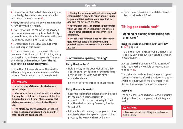
Operation
● If a window is obstructed when closing au-tomatically, the window stops at this pointand lowers immediately ››› .
● Next, check why the window does not closebefore attempting it again.
● If you try within the following 10 secondsand the window closes again with difficultyor there is an obstruction, the automatic clos-ing will stop working for 10 seconds.
● If the window is still obstructed, the win-dow will stop at this point.
● If there is no obvious reason why the win-dow cannot be closed, try to close it again bypulling the tab within ten seconds. The win-dow closes with maximum force. The roll-back function is now deactivated.
If more than 10 seconds pass, the windowwill open fully when you operate one of thebuttons. One-touch closing is reactivated.
WARNING
● Incorrect use of the electric windows canresult in injury.
● Always take the ignition key with you whenleaving the vehicle, even if you only intend tobe gone for a short time. Please ensure thatchildren are never left alone inside the vehi-cle.
● The electric windows will work until the ig-nition has been switched off and one of thefront doors has been opened.
● Closing the windows without observing andensuring it is clear could cause serious injuryto you and third parties. Make sure that noone is in the path of a window.
● Never allow people to remain in the vehiclewhen you close the vehicle from the outside.The windows cannot be opened even in anemergency.
● The roll-back function does not prevent fin-gers or other parts of the body gettingpinched against the window frame. Risk ofaccident.
Convenience opening/closing*
Using the door lock*
– Hold the key in the door lock of the driverdoor in either the locking or the unlockingposition until all windows are eitheropened or closed.
– Release the key to interrupt this function.
Using the remote control
– Keep the locking/unlocking button pressedfor the electric window risers toopen/close; if you stop pressing the but-ton, the window raising/lowering functionis stopped.
– If the automatic raising is stopped and im-mediately after, the opening button is keptpressed, the window risers will lower.
– Once the windows are completely closed,the turn signals will flash.
Tilting panoramic roof*
Opening or closing of the tilting pan-oramic roof
Read the additional information carefully››› page 11
The panoramic/tilting sunroof is opened andclosed by using the switch when the ignitionis switched on.
Always close the panoramic/tilting sunrooffully if you park the vehicle or leave it unat-tended ››› .
The tilting sunroof can be operated for up toabout ten minutes after the ignition has beenswitched off, provided the driver door andthe front passenger door are not opened.
Sun visor
The sun visor is opened and closed manually(independently of the panoramic/tilting sun-roof).
WARNING
● Incorrect use of the tilting sunroof can re-sult in injury.
122

Lights and visibility
● Never close the tilting sunroof without firstchecking that there are no obstructions. Riskof serious injury to you or others. Make surethat no one is in the path of the tilting sun-roof.
● Always take the vehicle key with you whenyou leave the vehicle.
● Never leave children or disabled persons inthe vehicle, particularly if they have access tothe keys. Unsupervised use of a key couldmean that the engine is started or that elec-trical equipment is used (e.g. electric tiltingsunroof) with a risk of accident. The doorscan be locked using the remote control key.This could become an obstacle for assistancein an emergency situation.
● The tilting sunroof continues to functionuntil one of the front doors is opened and thekey removed from the ignition.
● Ensure that no object and/or end is be-tween the glass and the sunroof when theone-touch opening/closing function is reset.
Convenience closing*
Using the door lock
– Hold the key in the door lock of the driverdoor in the locking position until the tiltingsunroof is closed.
– Release the key to interrupt this function.
Using the remote control
– Push the lock button on the remote controlfor approximately 3 seconds. The tiltingsunroof closes.
– Press the unlock button to interrupt thefunction.
Roll-back function of the tilting panor-amic sunroof*
The tilting panoramic sunroof has a roll-backfunction which prevents larger objects get-ting trapped when the roof is closed. The roll-back function does not prevent fingers get-ting pinched against the roof opening. Thetilting sunroof stops and opens again imme-diately if it is obstructed when closing.
Lights and visibility
Lights
Switching lights on and off
Read the additional information carefully››› page 21
Switching on the front fog lights*
– Turn the switch from position or tothe first stop and pull it. The symbol ofthe light control lights up.
Switching on the rear fog light (vehicles withfront fog lights)
– Turn the lights control from position or to the second stop and pull out ››› . Acontrol lamp on the instrument panel lightsup.
Switching on the rear fog light (vehicles withno front fog lights)
– Turn the light control to the end from posi-tion or and pull it. A control lamp onthe instrument panel lights up.
WARNING
Never drive with just the side lights on, thereis a risk of accident. The side lights are notbright enough to illuminate the road ahead »
123
Tech
nica
l dat
aA
dvic
eO
pera
tion
Emer
genc
ies
Saf
ety

Operation
and to ensure that other road users are ableto see you. Always use your dipped beamheadlights if it is dark or if visibility is poor.
Note
● The dipped beam headlights will only workwith the ignition on. The side lights come onautomatically when the ignition is turned off.
● If the lights are left on after the key hasbeen taken out of the ignition lock, an audi-ble warning sounds while the driver door re-mains open. This is a reminder to switch thelights off.
● The rear fog light is so bright that it candazzle drivers behind you. You should usethe rear fog light only when visibility is verypoor.
● The use of the lighting described here issubject to the relevant statutory require-ments.
Automatic lighting*
Activation
– Rotate the switch to the position, thisindication will light up.
Deactivation
– Turn the light switch to .
Automatic lighting
If automatic headlight control is switched on,dipped beam headlights are automaticallyswitched on by a photosensor if you drive in-to a tunnel, for example.
WARNING
● Even if the automatic headlight control isswitched on, the dipped beam headlights willnot be switched on with fog. Therefore, thedipped beam must be switched on manually.
Note
● For those vehicles with the automatic head-light system, when the key is removed fromthe ignition, the audible warning will onlysound if the light knob is in position or .
● If the daylight driving automatic light func-tion is switched on, the front fog lights orrear fog light cannot be switched on in addi-tion.
● The use of the lighting described here issubject to the relevant statutory require-ments.
● Do not put stickers on the windscreen infront of the sensor. This may cause disrup-tions or faults in the automatic lighting sys-tem.
● The rain sensor switches on the dippedbeam headlights when the windscreen wipershave been operating continuously for a fewseconds and it switches the lights off when
the continuous or interval wipe is switchedoff for some minutes.
Daytime running lights
››› table on page 2
The daytime running lights are enabled auto-matically when the ignition is switched on.
Daytime running lights are signalling devicesfor improving road safety. The lights are builtinto the headlights and come on each timethe ignition is turned on if the light switch isin position 0 or . It is automaticallyswitched off when the dipped beam lightsare turned on.
WARNING
The side lights or daytime driving lights arenot bright enough to illuminate the roadahead and to ensure that other road users areable to see you.
● Always use your dipped beam head lights ifit is raining or if visibility is poor.
● The rear lights do not come on with thedaytime driving light. A vehicle which doesnot have the rear lights on may not be visibleto other drivers in the darkness, if it is rain-ing or in conditions of poor visibility.
124
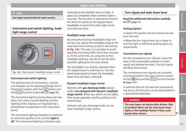
Lights and visibility
Note
See legal requirements for each country.
Instrument and switch lighting, head-light range control
Fig. 134 Dash panel: headlight range control
Instrument and switch lighting
The lighting level of instruments, controlsand displays can be adjusted through the in-fotainment system with the CAR button andthe SETUP function button ››› page 24.
The instrument lighting (some dials and nee-dles), the centre console lighting and thelighting of the displays are regulated by aphotodiode incorporated in the instrumentpanel.
The instrument lighting (needles) is switchedon when the ignition is on and the light isoff. The instrument lighting is dimmed auto-
matically as the daylight starts to fade. Itgoes out completely when ambient light isvery low. This function is intended to remindthe driver to switch on the dipped beamheadlights in good time when light condi-tions become poor.
Headlight range control
By using the electrical headlight range con-trol you can adjust the headlight range to theload level that is being carried in the vehicle››› Fig. 134. This way, it is possible to avoiddazzling oncoming traffic more than necessa-ry. At the same time, by using the correctheadlight settings, the driver has the bestpossible lighting for the road ahead.
The headlights can only be adjusted whenthe dipped beam is switched on. Turn thewheel downwards to lower the headlightbeam from the basic setting 0.
Dynamic headlight range control
Vehicles with gas discharge bulbs (xenonbulbs) are equipped with dynamic headlightrange control. When you switch on the lights,their range regulates itself according to thevehicle load.
Vehicles with gas discharge bulbs do nothave headlight range control.
Turn signal and main beam lever
Read the additional information carefully››› page 22
Parking lights
● Switch the ignition off and remove the keyfrom the lock.
● Move the turn signal lever up or down toturn the right or left-hand parking lights on,respectively.
Convenience turn signals
For the convenience turn signals, move thelever as far as possible upwards or down-wards and release the lever. The turn signalwill flash three times.
The convenience turn signals are activatedand deactivated in the Easy Connect systemvia the key and the Setup function button››› page 107.
In vehicles that do not have the correspond-ing menu, this function can be deactivated ina specialised workshop.
WARNING
The main beam can dazzle other drivers. Riskof accident! Never use the main beam head-lights or the headlight flasher if they coulddazzle other drivers. »
125
Tech
nica
l dat
aA
dvic
eO
pera
tion
Emer
genc
ies
Saf
ety

Operation
Note
● If the convenience turn signals are operat-ing (three flashes) and the other convenienceturn signals are switched on, the active partstops flashing and only flashes once in thenew part selected.
● The turn signals only work when the igni-tion is switched on. The corresponding warn-ing lamp or flashes in the instrumentpanel. The control lamp flashes when theturn signals are operated, provided a trailer iscorrectly attached and connected to the vehi-cle. If a turn signal bulb is defective, the con-trol lamp flashes at double speed. If the trail-er turn signal bulbs are defective, the controllamp does not light up. Change the bulb.
● The main beam headlights can only beswitched on if the dipped beam headlightsare already on. The warning lamp thencomes on in the instrument panel.
● The headlight flasher comes on for as longas you pull the lever – even if no other lightsare switched on. The warning lamp thencomes on in the instrument panel.
● When the parking lights are switched on,the headlight and the tail light on the corre-sponding side of the vehicle light up. Theparking lights will only work if the key is re-moved from the ignition. If said light is on, anaudible warning will be emitted while thedriver door is open.
● If the turn signal lever is left on after thekey has been taken out of the ignition lock,an acoustic signal sounds when the driver
door is opened. This is intended as a remind-er to switch off the turn signal, unless youwish to leave the parking light on.
Coming Home/Leaving Home Func-tion*
The Coming Home function is controlled man-ually. The Leaving Home function is control-led with a photosensor.
If the Coming Home or Leaving Home func-tion is connected, the front side and dippedlights, the tail lights and the number platelight will light up to provide assistance.
Coming home function
The Coming Home function is activated byswitching off the ignition and briefly flashingthe lights. When the driver door is opened,the Coming Home lighting comes on. If thedriver door is already open when the lightsare flashed briefly, the Coming Home lightingcomes on immediately.
When the last door of the vehicle or the rearlid is closed, the Coming Home functionstarts and the switching off the headlights isdelayed.
The Coming Home lighting switches off in thefollowing cases:
● On completion of the time period establish-ed for the delay in switching off the lights af-ter all the vehicle doors and the rear lid havebeen closed.
● If, 30 seconds after being connected, anydoors or the rear lid remain open.
● If the light switch is turned to position .
● If the ignition is switched on.
Automatic Leaving Home function
The Leaving Home function is activated whenthe vehicle is unlocked if:
● the light control is in position and
● the photosensor detects “darkness”.
The Leaving Home lighting switches off in thefollowing cases:
● If the time period for the delay in switchingoff the headlights has ended
● If the vehicle is locked again.
● If the light switch is turned to position .
● If the ignition is switched on.
Manual Leaving Home function
In vehicles without an automatic headlightsystem (light sensor), if the manual ComingHome function is activated when leaving thecar, upon returning to the car and unlockingit the manual Leaving Home function will beactivated automatically.
126

Lights and visibility
Note
● To activate the Coming/Leaving home func-tion, the rotary light switch must be in posi-tion and the light sensor must detectdarkness.
● If the ignition key is removed while thelights are on, the lights flash briefly and thedriver door opens, no audible warning isheard, since with the Coming Home functionon, the lights are automatically switched offafter a period of time (except when the lightswitch is in position or .
Adaptive headlights* (for drivinground bends)
Fig. 135 Cornering lighting using adaptiveheadlights.
When driving around bends, the headlightswill light the most important areas of theroad.
This cornering light gives better illuminationof the side of the road and the corner area.The dynamic lighting is controlled automati-cally according to speed and the steeringwheel angle.
The two main headlights move at differentangles to avoid that the front of the vehicle isleft completely in the dark.
Note
The system operates from a speed of about10 km/h (6 mph).
Fog lights with cornering function*
This is an additional light source to dippedbeam headlights to light up the road as abend is taken.
The cornering light operates with the lightsswitched on and when driving at less than40 Km/h (25 mph). Ignition occurs by turningthe steering or connecting the turn signal.
Forward gear
● If the steering wheel is turned to the right,or the right-hand turn signal operated, theright-hand fog light turns on.
● If the steering wheel is turned to the left, orthe left-hand turn signal operated, the left-hand fog light turns on.
In reverse, both fog lights turn on.
Note
When the fog lamps are on, the corneringfunction is activated and both headlights arecontinuously on.
Hazard warning lights
Read the additional information carefully››› page 22
The hazard warning lights are used to drawthe attention of other road users to your vehi-cle in emergencies.
If your vehicle breaks down:
1. Park your vehicle at a safe distance frommoving traffic.
2. Press the button to switch on the hazardwarning lights ››› .
3. Switch the ignition off.
4. Apply the handbrake.
5. For a manual gearbox, engage 1st gear;for an automatic gearbox, move the gearlever to P.
6. Use the warning triangle to draw the atten-tion of other road users to your vehicle.
7. Always take the vehicle key with you whenyou leave the vehicle. »
127
Tech
nica
l dat
aA
dvic
eO
pera
tion
Emer
genc
ies
Saf
ety
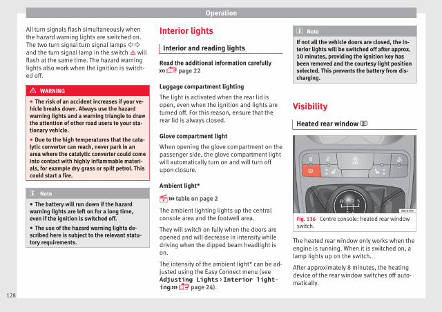
Operation
All turn signals flash simultaneously whenthe hazard warning lights are switched on.The two turn signal turn signal lamps and the turn signal lamp in the switch willflash at the same time. The hazard warninglights also work when the ignition is switch-ed off.
WARNING
● The risk of an accident increases if your ve-hicle breaks down. Always use the hazardwarning lights and a warning triangle to drawthe attention of other road users to your sta-tionary vehicle.
● Due to the high temperatures that the cata-lytic converter can reach, never park in anarea where the catalytic converter could comeinto contact with highly inflammable materi-als, for example dry grass or spilt petrol. Thiscould start a fire.
Note
● The battery will run down if the hazardwarning lights are left on for a long time,even if the ignition is switched off.
● The use of the hazard warning lights de-scribed here is subject to the relevant statu-tory requirements.
Interior lights
Interior and reading lights
Read the additional information carefully››› page 22
Luggage compartment lighting
The light is activated when the rear lid isopen, even when the ignition and lights areturned off. For this reason, ensure that therear lid is always closed.
Glove compartment light
When opening the glove compartment on thepassenger side, the glove compartment lightwill automatically turn on and will turn offupon closure.
Ambient light*
››› table on page 2
The ambient lighting lights up the centralconsole area and the footwell area.
They will switch on fully when the doors areopened and will decrease in intensity whiledriving when the dipped beam headlight ison.
The intensity of the ambient light* can be ad-justed using the Easy Connect menu (seeAdjusting Lights > Interior light-ing ››› page 24).
Note
If not all the vehicle doors are closed, the in-terior lights will be switched off after approx.10 minutes, providing the ignition key hasbeen removed and the courtesy light positionselected. This prevents the battery from dis-charging.
Visibility
Heated rear window
Fig. 136 Centre console: heated rear windowswitch.
The heated rear window only works when theengine is running. When it is switched on, alamp lights up on the switch.
After approximately 8 minutes, the heatingdevice of the rear window switches off auto-matically.
128

Lights and visibility
For the sake of the environment
The heated rear window should be switchedoff as soon as the glass is demisted. By sav-ing electrical power you can also save fuel.
Note
To avoid possible damage to the battery, anautomatic temporary disconnection of thisfunction is possible, coming back on whennormal operating conditions are re-establish-ed.
Sun visors
Fig. 137 Sun visor on the driver side.
The sun visors for the driver and the frontpassenger can be pulled out of their centralsupports and turned towards the doors in thedirection of the arrow ››› Fig. 137. Never pullthem downwards.
The driver sun visor has compartments forcards, and the passenger sun visor has avanity mirror with a cover*.
Note
Incorrect use of the sun visor (e.g. pullingthem downwards once they are open) may re-sult in broken hinges. This damage is not cov-ered by the vehicle warranty.
Windscreen wiper and rear win-dow wiper systems
Windscreen wipers
Read the additional information carefully››› page 23
WARNING
● Worn and dirty wiper blades reduce visibili-ty and safety levels while driving.
● In cold conditions you should not use thewash/wipe system unless you have warmedthe windscreen with the heating and ventila-tion system. The windscreen washer fluidcould otherwise freeze on the windscreen andobscure your view of the road.
● Always note the corresponding warnings››› page 54.
WARNING
The rain sensor* may not detect enough rainto switch on the wipers.
● If necessary, switch on the wipers manuallywhen water on the windscreen obstructs visi-bility.
CAUTION
In icy conditions, always check that the wiperblades are not frozen to the glass before us-ing the wipers for the first time. If you switchon the windscreen wipers when the wiperblades are frozen to the windscreen, youcould damage both the wiper blades and thewiper motor.
Note
● The windscreen wipers will only work whenthe ignition is switched on.
● The heat output of the heated jets* is con-trolled automatically when the ignition isswitched on, depending upon the outsidetemperature.
● In certain versions of vehicles with alarms,the windscreen wiper will only work in inter-val/rain sensor mode when the ignition is onand the bonnet closed.
● When the interval wipe function is on, theintervals are directly proportional to thespeed. This way, the higher the vehicle speedthe shorter the intervals. »
129
Tech
nica
l dat
aA
dvic
eO
pera
tion
Emer
genc
ies
Saf
ety

Operation
● If you stop the vehicle with the windscreenwiper in position 1 or 2, it will automaticallychange to a lower position speed. The setspeed will be resumed when the vehicle pullsaway.
● The windscreen will be wiped again afterapproximately five seconds once the “auto-matic wash/wipe system” has been activa-ted, provided the vehicle is moving (drip func-tion). If you activate the wipers less than 3seconds after the drip function, a new washsequence will begin without performing thelast wipe. For the “drip” function to workagain, you have to turn the ignition off andthen on again.
● Do not put stickers on the windscreen infront of the rain sensor*. This may cause sen-sor disruption or faults.
Rear window wiper
Fig. 138 Windscreen wiper lever: rear windowwiper.
Switching on the interval wipe
– Press the lever forward to position 6
››› Fig. 138. The wiper will wipe the windowapproximately every 6 seconds.
Switching off the interval wipe function
– Pull the lever back from position 6 towardthe steering wheel. The wiper will continueto function for a short period if you switchoff whilst the wipers are in motion.
Switching on the window wiper and washersystem
– Press the lever fully forwards to position 7
››› Fig. 138 . The wiper and washer operateat the same time. The rear window washsystem will function as long as you hold thelever in this position.
– Release the lever. The washer system stopsand the wipers continue until the end ofthe cycle.
– Move the lever towards the steering wheelto switch off.
WARNING
● Worn and dirty wiper blades reduce visibili-ty and safety levels while driving.
● Always note the corresponding warnings››› page 54.
CAUTION
In icy conditions, always check that the wiperblade is not frozen to the glass before usingthe wiper for the first time. If you switch onthe wiper when the wiper blade is frozen tothe glass, this could damage both the wiperblade and the wiper motor.
Note
● The rear window wiper will only work whenthe ignition is switched on.
● Depending on the version of the model,when you engage reverse gear and with theheadlight wiper activated, this can start awipe.
Headlight washer*
The headlight washers clean the headlightlenses.
The headlight washers are activated auto-matically when the windscreen washer isused and the window wiper lever is pulled to-wards the steering wheel for at least 1.5 sec-onds – provided the dipped beam headlightsor main beams are switched on. Clean offstubborn dirt (insects, etc.) from the head-lights at regular intervals, for instance whenfilling the fuel tank.
130

Lights and visibility
Note
● To ensure that the headlight washers workproperly in winter, keep the nozzle holders inthe bumper free of snow and remove any icewith a de-icer spray.
● To remove water, the windscreen wiperswill be activated from time to time, the head-light washers will be activated every three cy-cles.
Rear view mirrors
Interior mirror
It is dangerous to drive if you cannot seeclearly through the rear window.
Interior mirror with automatic anti-dazzlefunction*
The anti-dazzle function is activated everytime the ignition is switched on.
When the anti-dazzle function is enabled, theinterior rear vision mirror will darken auto-matically according to the amount of light itreceives. The anti-dazzle function is cancel-led if reverse gear is engaged.
Note
● The automatic anti-dazzle function will onlywork properly if the sun blind* for the rear
window is retracted and there are no otherobjects preventing light from reaching the in-terior rear vision mirror.
● If you have to stick any type of sticker onthe windscreen, do not do so in front of thesensors. Doing so could prevent the anti-daz-zle function from working well or even fromworking at all.
Folding in the exterior mirrors man-ually
The exterior mirrors of the vehicle may be fol-ded in. For this, press the mirror housing to-wards the vehicle.
Note
Before washing the vehicle with an automaticcar wash, fold in the exterior mirrors to avoiddamage.
Electric exterior mirrors*
Fig. 139 Exterior mirror controls.
Read the additional information carefully››› page 13
The exterior mirrors can be adjusted usingthe rotary knob in the driver door.
Basic setting of exterior mirrors
1. Turn knob ››› Fig. 139 to position L (left ex-terior mirror).
2. Turn the rotary knob to position the exteri-or mirror so that you have a good view tothe rear of the vehicle.
3. Turn the knob to position R (right exteriormirror).
4. Swivel the rotary knob to position the ex-terior mirror so that you have a good viewto the rear of the vehicle ››› . »
131
Tech
nica
l dat
aA
dvic
eO
pera
tion
Emer
genc
ies
Saf
ety

Operation
Heated exterior mirrors*
– Press the demisting button ››› Fig. 136
– The mirrors demist for some minutes toprevent draining the battery unnecessarily.
– If necessary, press the button again to re-peat the function.
– The exterior mirror heating is not activatedin temperatures above approximately+20°C (+68°F).
Folding in the exterior mirrors electrically*
– Turn the control ››› Fig. 139 to position tofold in the exterior mirrors. You should al-ways fold in the exterior mirrors if you aredriving through an automatic car wash.This will help prevent damage.
Folding exterior mirrors back out to the ex-tended position*
– Turn the knob to position L or R to returnthe exterior mirrors to their original posi-tion ››› .
WARNING
● Convex or aspheric mirrors increase thefield of vision however the objects appearsmaller and further away in the mirrors. If youuse these mirrors to estimate the distance tovehicles behind you when changing lane, youcould make a mistake. Risk of accident.
● If possible, use the rear vision mirror to es-timate distances to vehicles behind you.
● Make sure that you do not get your fingertrapped between the mirror and the mirrorbase when folding back the mirrors. Risk ofinjury!
For the sake of the environment
The exterior mirror heating should be switch-ed off when it is no longer needed. Other-wise, it is an unnecessary fuel waste.
Note
● If the electrical adjustment ever fails to op-erate, the mirrors can be adjusted by hand bylightly pressing the edge of the mirror glass.
● In vehicles with electric exterior mirrors,the following points should be observed: if,due to an external force (e.g. being knockedwhile manoeuvring), the adjustment of themirror housing is altered, the mirror will haveto be fully folded electrically. Do not readjustthe rear vision mirror housing by hand, asthis will interfere with the mirror adjusterfunction.
● The rear vision mirrors can be adjusted sep-arately or simultaneously, as describedabove.
● The fold-in function on the exterior mirrorswill not activate at speeds over 40 km/h(25 mph).
Seats and head restraints
Adjusting the seat and head re-straints
Adjusting the front seats
Read the additional information carefully››› page 12
WARNING
The safe driving chapter contains importantinformation, tips, suggestions and warningsthat you should read and observe for yourown safety and the safety of your passengers››› page 56.
WARNING
● Never adjust the driver or front passengerseat while the vehicle is in motion. While ad-justing your seat, you will assume an incor-rect sitting position. Risk of accidents. Adjustthe driver or front passenger seat only whenthe vehicle is stationary.
● To reduce the risk of injury to the driver andfront passenger in case of a sudden brakingor an accident, never drive with the backresttilted towards the rear. The maximum protec-tion of the seat belt can be achieved onlywhen the backrests are in an upright positionand the driver and front passenger have prop-erly adjusted their seat belts. The further the
132

Seats and head restraints
backrests are tilted to the rear, the greaterthe risk of injury due to improper positioningof the belt web!
● Exercise caution when securing the seatheight into forwards/backwards position. In-juries can be caused if the seat height is ad-justed without due care and attention.
● To move the seat forwards and backwards,pull upwards and not sideways on the lever,as the force exerted on it in that directioncould damage it.
Folding and lifting the backrest of thefront seats
3 Applies to vehicles with 3 doors:
Fig. 140 Front seats: lever for folding downthe backrest.
Read the additional information carefully››› page 12
Vehicles without the Easy-Entry function
– To fold the backrest, pull the lever 1 up-wards and push the backrest forwards.
– To unfold the backrest, push it back.
Vehicles with the Easy-Entry function
– To fold the backrest, pull the lever 1 up-wards and push the backrest forwards. Youcan push the seat forwards at the sametime to make entry to the rear seats easier.
– To unfold the backrest, first move the seatcompletely back.
The Easy-Entry function facilitates the accessto the vehicle rear seats. Before lifting thebackrest, return the seat to the original posi-tion. The seat inserts when the backrest is lif-ted.
Adjusting or disassembling the headrestraints
Fig. 141 Adjusting and removing the head re-straints.
Read the additional information carefully››› page 12
Adjusting height (front seats)
– Press the button on the side and pull up-wards to the desired position.
– To lower the head restraint, press the but-ton and push head restraint downwards.
– Make sure that it engages securely into oneof its positions.
Adjusting height (rear seats)
– Press the button on the side and pull up-wards to the desired position.
– To lower the head restraint, press the but-ton and push head restraint downwards. »
133
Tech
nica
l dat
aA
dvic
eO
pera
tion
Emer
genc
ies
Saf
ety
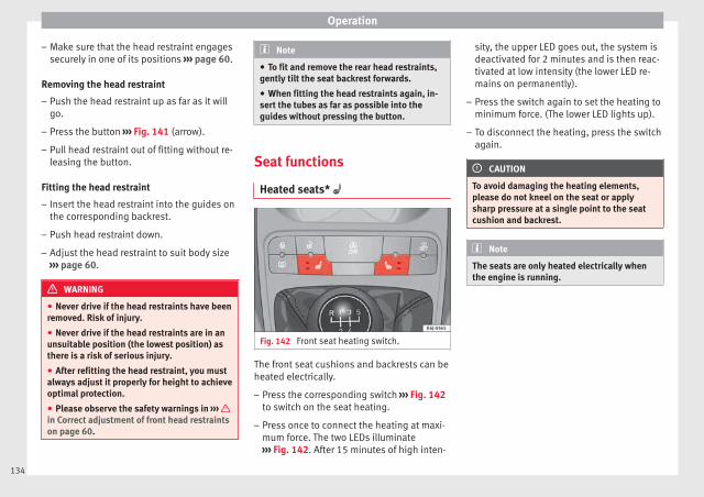
Operation
– Make sure that the head restraint engagessecurely in one of its positions ››› page 60.
Removing the head restraint
– Push the head restraint up as far as it willgo.
– Press the button ››› Fig. 141 (arrow).
– Pull head restraint out of fitting without re-leasing the button.
Fitting the head restraint
– Insert the head restraint into the guides onthe corresponding backrest.
– Push head restraint down.
– Adjust the head restraint to suit body size››› page 60.
WARNING
● Never drive if the head restraints have beenremoved. Risk of injury.
● Never drive if the head restraints are in anunsuitable position (the lowest position) asthere is a risk of serious injury.
● After refitting the head restraint, you mustalways adjust it properly for height to achieveoptimal protection.
● Please observe the safety warnings in ››› in Correct adjustment of front head restraintson page 60.
Note
● To fit and remove the rear head restraints,gently tilt the seat backrest forwards.
● When fitting the head restraints again, in-sert the tubes as far as possible into theguides without pressing the button.
Seat functions
Heated seats*
Fig. 142 Front seat heating switch.
The front seat cushions and backrests can beheated electrically.
– Press the corresponding switch ››› Fig. 142to switch on the seat heating.
– Press once to connect the heating at maxi-mum force. The two LEDs illuminate››› Fig. 142. After 15 minutes of high inten-
sity, the upper LED goes out, the system isdeactivated for 2 minutes and is then reac-tivated at low intensity (the lower LED re-mains on permanently).
– Press the switch again to set the heating tominimum force. (The lower LED lights up).
– To disconnect the heating, press the switchagain.
CAUTION
To avoid damaging the heating elements,please do not kneel on the seat or applysharp pressure at a single point to the seatcushion and backrest.
Note
The seats are only heated electrically whenthe engine is running.
134
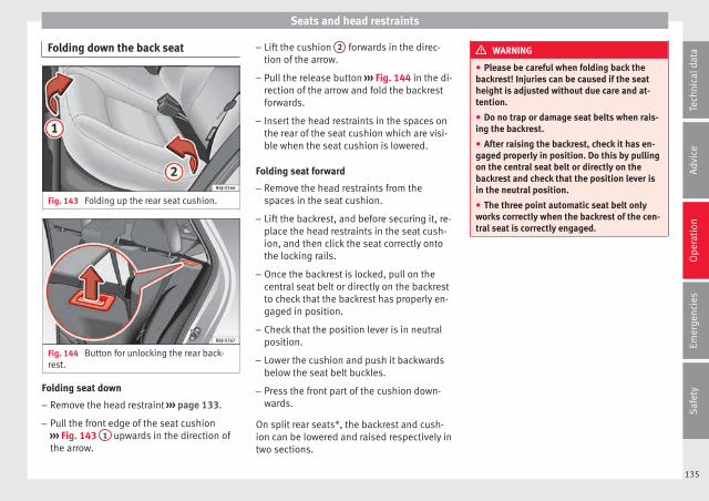
Seats and head restraints
Folding down the back seat
Fig. 143 Folding up the rear seat cushion.
Fig. 144 Button for unlocking the rear back-rest.
Folding seat down
– Remove the head restraint ››› page 133.
– Pull the front edge of the seat cushion››› Fig. 143 1 upwards in the direction ofthe arrow.
– Lift the cushion 2 forwards in the direc-tion of the arrow.
– Pull the release button ››› Fig. 144 in the di-rection of the arrow and fold the backrestforwards.
– Insert the head restraints in the spaces onthe rear of the seat cushion which are visi-ble when the seat cushion is lowered.
Folding seat forward
– Remove the head restraints from thespaces in the seat cushion.
– Lift the backrest, and before securing it, re-place the head restraints in the seat cush-ion, and then click the seat correctly ontothe locking rails.
– Once the backrest is locked, pull on thecentral seat belt or directly on the backrestto check that the backrest has properly en-gaged in position.
– Check that the position lever is in neutralposition.
– Lower the cushion and push it backwardsbelow the seat belt buckles.
– Press the front part of the cushion down-wards.
On split rear seats*, the backrest and cush-ion can be lowered and raised respectively intwo sections.
WARNING
● Please be careful when folding back thebackrest! Injuries can be caused if the seatheight is adjusted without due care and at-tention.
● Do no trap or damage seat belts when rais-ing the backrest.
● After raising the backrest, check it has en-gaged properly in position. Do this by pullingon the central seat belt or directly on thebackrest and check that the position lever isin the neutral position.
● The three point automatic seat belt onlyworks correctly when the backrest of the cen-tral seat is correctly engaged.
135
Tech
nica
l dat
aA
dvic
eO
pera
tion
Emer
genc
ies
Saf
ety

Operation
Transport and practicalequipment
Practical equipment
Glove compartment
Fig. 145 Passenger side: glove compartment.
Fig. 146 Glove compartment: storage com-partment for instruction manual.
The compartment can be opened by pullingthe lever ››› Fig. 145.
This compartment can hold documents in A4format, a water bottle of 1.5 L, etc.
Depending on the vehicle equipment, the CDplayer is located in the glove compartment.Separate operating instructions are enclosedfor this equipment in the corresponding In-struction Manual.
WARNING
Always keep the storage compartment coverclosed while the vehicle is in motion in orderto reduce the risk of injury caused by a sud-den braking or by an accident.
Storage compartment on the driverside
Fig. 147 Compartment on the driver side
There is a storage compartment on the driverside
Storage compartment under the frontseats*
Fig. 148 Storage compartment under theright front passenger seat.
To open
– The compartment is opened by pulling onthe lever and assisting it with your hand.
To close
– Press the cover inwards until the closeddrawer “clicks” into position.
Note
The storage drawer will hold a maximumweight of 1.5 kg.
136

Transport and practical equipment
Storage pocket in the seat*
Fig. 149 Storage pocket.
There is a storage pocket on the rear of thefront seats.
Storage compartment in front doorpanel*
In this storage compartment a 1.5l water bot-tle, etc. can be stored.
Front drink holder*
Fig. 150 Front drink holders in the centre con-sole.
In the central console, in front of the gear lev-er, there are two drinks holders ››› Fig. 150.
WARNING
● Do not put hot drinks in the drink holders.During sudden or normal driving manoeuvres,when braking suddenly or in case of an acci-dent, the hot drink could spill. Risk of scald-ing.
● Never use rigid materials (for example,glass or ceramic), since they could cause in-jury in the case of an accident.
● When travelling, the drinks holder shouldalways be closed to prevent risk in the eventof sudden breaking or accident.
Rear drink holder*
Fig. 151 Drinks holder in the centre console.
On the rear part of the centre console, behindthe handbrake, there is a drink holder* in-stalled ››› Fig. 151.
This drinks holder has a capacity for a bottleof up to 1 litre.
137
Tech
nica
l dat
aA
dvic
eO
pera
tion
Emer
genc
ies
Saf
ety

Operation
Front ashtray*
Fig. 152 Front ashtray.
Opening and closing the ashtray
– To open the ashtray, lift the cover››› Fig. 152.
– To close, push the cover down.
Emptying the ashtray
– Extract the ashtray and empty it.
WARNING
Never put paper in the ashtray. Hot ash couldignite the paper in the ashtray and cause afire.
Cigarette lighter*
Fig. 153 Lighter.
– Press on the cigarette lighter ››› Fig. 153 toactivate it ››› .
– Wait for the lighter to spring out.
– Pull out the cigarette lighter and light thecigarette on the glowing coil.
WARNING
● Improper use of the cigarette lighter canlead to serious injuries or start a fire.
● Using the lighter carefully. Carelessness ornegligence when using the cigarette lightercan cause burns and serious injuries.
● The lighter only works when the ignition isturned on or the engine is running. To avoidthe risk of fire, never leave children alone in-side the vehicle.
Electrical power socket
Fig. 154 Front power socket.
The 12 Volt cigarette lighter power socket canalso be used for other electrical componentswith a power rating of up to 120 Watt. Whenthe engine is switched off, however, the vehi-cle battery will discharge. For further informa-tion see ››› page 190.
WARNING
The power sockets and the connected acces-sories will only operate when the ignition ison or when the engine is running. Improperuse of the sockets or electrical accessoriescan lead to serious injuries or cause a fire. Toavoid the risk of injury, never leave childrenalone inside the vehicle.
138
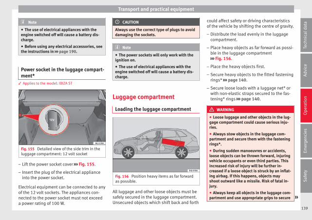
Transport and practical equipment
Note
● The use of electrical appliances with theengine switched off will cause a battery dis-charge.
● Before using any electrical accessories, seethe instructions in ››› page 190.
Power socket in the luggage compart-ment*
3 Applies to the model: IBIZA ST
Fig. 155 Detailed view of the side trim in theluggage compartment: 12 volt socket
– Lift the power socket cover ››› Fig. 155.
– Insert the plug of the electrical applianceinto the power socket.
Electrical equipment can be connected to anyof the 12 volt sockets. The appliances con-nected to the power socket must not exceeda power rating of 100 W.
CAUTION
Always use the correct type of plugs to avoiddamaging the sockets.
Note
● The power sockets will only work with theignition on.
● The use of electrical appliances with theengine switched off will cause a battery dis-charge.
Luggage compartment
Loading the luggage compartment
Fig. 156 Position heavy items as far forwardas possible.
All luggage and other loose objects must besafely secured in the luggage compartment.Unsecured objects which shift back and forth
could affect safety or driving characteristicsof the vehicle by shifting the centre of gravity.
– Distribute the load evenly in the luggagecompartment.
– Place heavy objects as far forward as possi-ble in the luggage compartment››› Fig. 156.
– Place the heavy objects first.
– Secure heavy objects to the fitted fasteningrings* ››› page 140.
– Secure loose loads with a luggage net* orwith non-elastic straps secured to the fas-tening* rings ››› page 140.
WARNING
● Loose luggage and other objects in the lug-gage compartment could cause serious inju-ries.
● Always stow objects in the luggage com-partment and secure them with the fasteningrings*.
● During sudden manoeuvres or accidents,loose objects can be thrown forward, injuringvehicle occupants or even third parties. Thisincreased risk of injury will be further in-creased if a loose object is struck by an inflat-ing airbag. If this happens, objects mayshoot outward like a missile. Risk of fatal in-jury.
● Always keep all objects in the luggage com-partment and use appropriate grips to secure »
139
Tech
nica
l dat
aA
dvic
eO
pera
tion
Emer
genc
ies
Saf
ety

Operation
them, particularly in the case of heavyobjects.
● Never exceed the allowed axle weights orallowed maximum weight. If said weights areexceeded, the driving characteristics of thevehicle may change, leading to accidents, in-juries and damage to the vehicle.
● Please note that the centre of gravity mayshift when transporting heavy objects; thismay affect vehicle handling and lead to an ac-cident. Therefore, it is essential to adjustyour speed and driving style accordingly, toavoid accidents.
● Never leave your vehicle unattended, espe-cially when the rear lid is open. Childrencould climb into the luggage compartment,closing the door behind them; they will betrapped and run the risk of death.
● Never allow children to play in or aroundthe vehicle. Close and lock all the doors andrear lid when you leave the vehicle. Beforeyou lock the vehicle, make sure that there areno adults or children in the vehicle.
● Please observe the notes on the ››› page 56.
CAUTION
Hard objects on the rear shelf could chafeagainst the wires of the heating element inthe heated rear window and cause damage.
Note
● The tyre pressure must be adjusted accord-ing to the load. When necessary check thetyre pressures on the label located on the in-side fuel tank flap ››› page 212.
● Air circulation in the vehicle helps reducefogging of the windows. Used air escapesthrough ventilation slits in the side trim ofthe luggage compartment. Ensure that theventilation slots are never covered.
● Straps for securing the load to the fasten-ing rings* are commercially available from ac-cessory shops.
Fastening rings*3 Applies to the model: IBIZA ST
Fig. 157 Location of fastening rings in lug-gage compartment.
There may be four fastening rings included inthe luggage compartment for fastening lug-gage and other objects ››› Fig. 157 (arrows).
– Always use suitable and undamaged strapsto secure luggage and other objects to thefastening rings ››› in Loading the lug-gage compartment on page 139.
– Pull up the fastening rings to attach thestraps.
Example: An object weighing 4.5 kg is lyingunsecured in the vehicle. During a frontal col-lision at a speed of 50 km/h (31 mph), thisobject generates a force corresponding to 20times its weight. That means that the effec-tive weight of the object increases to approxi-mately 90 kg. You can imagine the severity ofthe injuries which might be sustained if this“object” strikes an occupant as it fliesthrough the interior of the vehicle. This in-creased risk of injury will be further increasedif a loose object is struck by an inflating air-bag.
WARNING
● If pieces of baggage or other objects are se-cured to the fastening rings with inappropri-ate or damaged retaining cords, injuriescould result in the event of braking manoeu-vres or accidents.
● Never secure a child seat on the fasteningrings.
140
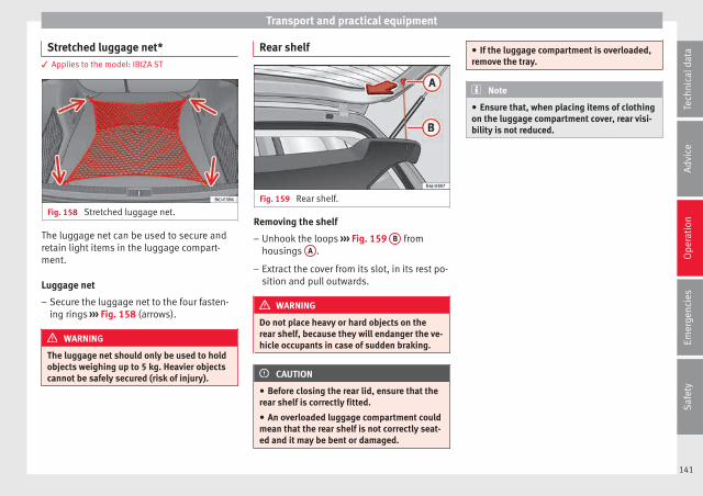
Transport and practical equipment
Stretched luggage net*3 Applies to the model: IBIZA ST
Fig. 158 Stretched luggage net.
The luggage net can be used to secure andretain light items in the luggage compart-ment.
Luggage net
– Secure the luggage net to the four fasten-ing rings ››› Fig. 158 (arrows).
WARNING
The luggage net should only be used to holdobjects weighing up to 5 kg. Heavier objectscannot be safely secured (risk of injury).
Rear shelf
Fig. 159 Rear shelf.
Removing the shelf
– Unhook the loops ››› Fig. 159 B fromhousings A .
– Extract the cover from its slot, in its rest po-sition and pull outwards.
WARNING
Do not place heavy or hard objects on therear shelf, because they will endanger the ve-hicle occupants in case of sudden braking.
CAUTION
● Before closing the rear lid, ensure that therear shelf is correctly fitted.
● An overloaded luggage compartment couldmean that the rear shelf is not correctly seat-ed and it may be bent or damaged.
● If the luggage compartment is overloaded,remove the tray.
Note
● Ensure that, when placing items of clothingon the luggage compartment cover, rear visi-bility is not reduced.
141
Tech
nica
l dat
aA
dvic
eO
pera
tion
Emer
genc
ies
Saf
ety

Operation
Rear shelf with storage compartment*3 Applies to the model: IBIZA ST
Fig. 160 Luggage compartment: removingstorage compartment.
Fig. 161 Accessing storage compartment.
To remove the storage compartment
– Remove the rear shelf and pull the storagecompartment upwards holding it by theedges ››› Fig. 160.
The storage compartment can be accessedfrom the rear seats by lifting the front part ofthe rear shelf ››› Fig. 161.
WARNING
Do not place heavy or hard objects on therear shelf, because they will endanger the ve-hicle occupants in case of sudden braking.
CAUTION
● Before closing the rear lid, ensure that therear shelf is correctly fitted.
● An overloaded luggage compartment couldmean that the rear shelf is not correctly seat-ed and it may be bent or damaged.
● If the luggage compartment is overloaded,remove the tray.
● The load in the storage compartmentshould not exceed 3 kg.
Note
● Ensure that, when placing items of clothingon the luggage compartment cover, rear visi-bility is not reduced.
● If your vehicle has a storage compartment*,only place light objects inside.
Roof rack/roof luggage rack*
Introduction
Please observe the following points if you in-tend to carry loads on the roof:
● For safety reasons, only luggage racks andaccessories supplied by SEAT Official Serv-ices are recommended.
● It is essential that you follow the assemblyinstructions included with the bars exactly,being especially careful to position front andrear luggage compartment cover bars on thespecial housings in the longitudinal bars.You must also respect their position accord-ing to the direction of travel indicated in theassembly manual. Not following these in-structions may damage the bodywork.
● Pay special attention to the tightening tor-que of the attachment bolts and check themfollowing a short journey. If necessary, re-tighten the bolts and check them at regularintervals.
● Distribute the load evenly. A maximum loadof 40 kg is permitted for each roof rack sys-tem support bar, the load must be distrib-uted evenly along the entire length. However,the maximum load permitted for the entireroof (including the support system) of 75 kgmust not be exceeded nor the total weightrecommended for the entire vehicle. See the“Technical Data” section.
142
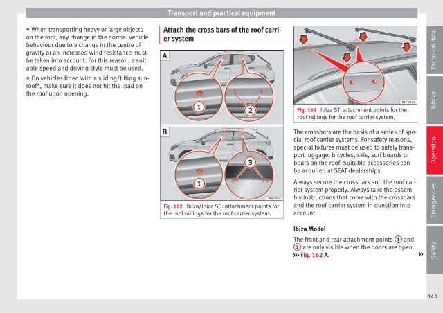
Transport and practical equipment
● When transporting heavy or large objectson the roof, any change in the normal vehiclebehaviour due to a change in the centre ofgravity or an increased wind resistance mustbe taken into account. For this reason, a suit-able speed and driving style must be used.
● On vehicles fitted with a sliding/tilting sun-roof*, make sure it does not hit the load onthe roof upon opening.
Attach the cross bars of the roof carri-er system
Fig. 162 Ibiza/Ibiza SC: attachment points forthe roof railings for the roof carrier system.
Fig. 163 Ibiza ST: attachment points for theroof railings for the roof carrier system.
The crossbars are the basis of a series of spe-cial roof carrier systems. For safety reasons,special fixtures must be used to safely trans-port luggage, bicycles, skis, surf boards orboats on the roof. Suitable accessories canbe acquired at SEAT dealerships.
Always secure the crossbars and the roof car-rier system properly. Always take the assem-bly instructions that come with the crossbarsand the roof carrier system in question intoaccount.
Ibiza Model
The front and rear attachment points 1 and2 are only visible when the doors are open
››› Fig. 162 A. »
143
Tech
nica
l dat
aA
dvic
eO
pera
tion
Emer
genc
ies
Saf
ety

Operation
Ibiza SC Model
The front attachment points 1 are only visi-ble when the doors are open; the rear attach-ment points 3 are marked on the top edgeof the side window with arrow heads››› Fig. 162 B.
Ibiza ST Model
The crossbars are assembled on the roof rail-ings. The attachment points can be seen onthe inside of the roof railings ››› Fig. 163.
WARNING
Incorrect attachment and use of the cross-bars and the roof carrier system may causethe whole system to detach from the roof andcause an accident and injuries.
● Always take the manufacturer assembly in-structions into account.
● Use only crossbars and the roof carrier sys-tem when they are in perfect condition andare properly secured.
● Always secure the crossbars and the roofcarrier system properly.
● Check threaded joints and attachmentstravelling and if necessary tighten them afteryou have travelled a short distance. Whenmaking long trips, check the threaded jointswhenever you stop for a rest.
● Always fit the special roof carrier systemscorrectly for wheels, skis and surfboards, etc.
● Do not modify or repair the crossbars orroof carrier system.
Note
Always read the assembly instructions thatcome with the crossbars and the roof carriersystem carefully and keep them in the vehi-cle.
Air conditioning
Heating, ventilation and cool-ing
General notes
Read the additional information carefully››› page 39
Pollution filter
The pollution filter (a combined particulatefilter and active carbon filter) serves as a bar-rier against impurities in the outside air, in-cluding dust and pollen.
For the climate control system to work withmaximum efficiency, the pollution filter mustbe replaced at the specified intervals in theMaintenance Programme.
If the filter loses efficiency prematurely dueto use in areas reaching very high pollutionlevels, the pollen filter must be changedmore frequently than stated in the ServiceSchedule.
WARNING
Reduced visibility through the windows in-creases the risk of serious accidents.
● Always ensure that all windows are free ofice and snow, and that they are not fogged,
144

Air conditioning
so as to maintain good visibility of everythingoutside.
● The maximum heat output required to de-frost windows as quickly as possible is onlyavailable when the engine has reached itsnormal running temperature. Only drive whenyou have good visibility.
● Always ensure that you use the heatingsystem, fresh air system, air conditioner andthe heated rear window to maintain good visi-bility to the outside.
● Never leave the air recirculation on for along period of time. If the cooling system isswitched off and air recirculation modeswitched on, the windows can mist over veryquickly, considerably limiting visibility.
● Switch air recirculation mode off when it isnot required.
WARNING
Stuffy or used air will increase fatigue and re-duce driver concentration possibly resultingin a serious accident.
● Never leave the fresh air fan turned off oruse the air recirculation for long periods oftime; the air in the vehicle interior will not berefreshed.
CAUTION
● If you suspect that the air conditioner isdamaged, switch it off with the A/C button to
prevent further damage and have it checkedby a specialised workshop.
● Repairs to the air conditioner require spe-cialist knowledge and special tools. There-fore, we recommend you to take the vehicleto a specialised workshop.
Note
● If the humidity and temperature outside thevehicle are high, condensation can drip offthe evaporator in the cooling system andform a pool underneath the vehicle. This isnormal and does not indicate a leak.
● Keep the air intake slots in front of thewindscreen free of snow, ice and leaves to en-sure heating and cooling are not impaired,and to prevent the windows from mistingover.
● The air from the vents flows through the ve-hicle interior and is extracted by slots in theluggage compartment designed for this pur-pose. Therefore, you should avoid obstruct-ing these slots with any kind of object.
● The air conditioner operates most effective-ly with the windows and the sliding/tiltingsunroof* closed. However, if the temperatureinside the vehicle is excessive because of thesun, the air inside can be cooled faster byopening the windows for a short time.
● Do not smoke while air recirculation modeis on, as smoke drawn into the air condition-
ing system leaves residue on the evaporator,producing a permanent unpleasant odour.
● At low outside temperatures, the compres-sor switches off automatically and cannot beswitched on even with the AUTO button.
● It is advisable to turn on the air condition-ing at least once a month, to lubricate thesystem gaskets and prevent leaks. If a de-crease in the cooling capacity is detected, aTechnical Service should be consulted tocheck the system.
● To ensure correct operation, the grilles onboth sides of the screen must not be obstruc-ted
● When the engine is under extreme strain,switch off the compressor for a moment.
Economic use of the air conditioning
When the air conditioning is switched on, thecompressor consumes engine power and hasinfluence on fuel consumption. Consider thefollowing points in order to have the systemoperating in the minimum possible time.
● If the vehicle interior has overheated due toan excessive solar radiation, it is best toopen the windows or doors to allow the hotair to escape.
● While in motion, the air conditioningshould not be switched on if the windows orthe sunroof* are open.
145
Tech
nica
l dat
aA
dvic
eO
pera
tion
Emer
genc
ies
Saf
ety

Operation
Air outlets
Fig. 164 Air vents
Air distribution
Symbol ››› page 146C
Main air output through out-lets
1, 2
5
1, 2, 5
3, 4
Outlets 3 and 4 can be closed or openedseparately using the slats and the air flow di-rected as required.
Heating and fresh air
Controls
Fig. 165 Heating controls on the dash panel.
● Use turn controls A , B and C ››› Fig. 165to adjust the temperature, blower speed andair distribution.
● Press the D button to switch air recircula-tion mode on or off. When the function is ac-tivated, a warning light on the button isturned on.
Temperature
Switch A adjusts temperature. The desiredtemperature inside the vehicle cannot belower than the ambient temperature. Maxi-mum heat output, which is needed to defrostthe windows quickly, is only available whenthe engine has reached its operating temper-ature.
146

Air conditioning
Blower
The air flow can be set at four speeds withswitch B . The blower should always be setat the lowest speed when driving slowly.
Air distribution
Control C for setting the flow of air in the re-quired direction.
– Air distribution towards the windscreenin order to demist. For safety reasons, it isnot recommended to switch air recirculationon.
– Air distribution to upper body.
– Air distribution to footwell
– Air distribution to the windscreen andthe footwell.
WARNING
● For your safety, the windows should neverbe fogged up or covered with snow or ice.This is essential to ensure good visibility.Please familiarise yourself with the correctoperation of the heating and ventilation sys-tem, including the demist/defrost functionsfor the windows.
Note
● Please consider the general notes››› page 144.
Air recirculation
Air recirculation prevents unpleasant smellsfrom entering the interior.
Connecting the recirculation
In any position of rotary switch C exceptthaw:
● Press button D ››› Fig. 165 and the lamp inthe button will illuminate.
Disconnecting the recirculation
● If the lamp is on, press button D and thelamp will go off, indicating that the entry ofoutside air has been activated.
If the rotary switch C ››› Fig. 165 is in thethaw position, the recirculation flap will al-ways be open and air will always enter fromthe outside.
If the rotary switch C is switched from anyposition to the thaw position, recirculationwill be automatically deactivated.
WARNING
● In air recirculation mode, no cold air fromthe outside enters the vehicle interior. Thewindows can quickly fog over if the heating isswitched off. Therefore, never leave the air re-circulation mode switched on for a long time(risk of accident).
Vehicle ventilation or heating
Ventilating the vehicle interior
– Turn the temperature selector ››› Fig. 165A anticlockwise.
– Turn blower switch B to any of the headsettings 1 -4.
– Set the airflow to the desired direction us-ing air distribution control C .
– Open the relevant air outlets.
Interior heating
– Turn the temperature selector ››› Fig. 165A clockwise to select the desired tempera-
ture.
– Turn blower switch B to any of the headsettings 1 -4.
– Set the airflow to the desired direction us-ing air distribution control C .
– Open the relevant air outlets.
Defrosting the windscreen
– Turn the temperature selector ››› Fig. 165A clockwise to reach the maximum tem-
perature.
– Turn the blower switch B to setting 4.
– Turn air distribution control to .
– Close outlet 3 . »
147
Tech
nica
l dat
aA
dvic
eO
pera
tion
Emer
genc
ies
Saf
ety

Operation
– Open and turn outlet 4 towards the sidewindows.
Keeping the windscreen and the side win-dows demisted
– Turn the temperature selector ››› Fig. 165A to the heating area.
– Turn blower switch B to any of the headsettings 2 -3.
– Turn air distribution control to .
– Close outlets 3
– Open and turn outlets 4 towards side win-dows.
Once the windows are demisted and as a pre-ventive measure, the control C can be set inposition , thus obtaining greater comfortwhile preventing the windows from mistingagain.
Heating
Maximum heat output, which is needed todefrost the windows quickly, is only availablewhen the engine has reached its operatingtemperature.
Note
Remember that the temperature of the enginecoolant should be optimum to ensure that theheating system functions correctly (except invehicles fitted with additional heating*).
Air conditioning*
Controls
Fig. 166 Air conditioning controls on thedash panel.
Temperature selector ››› page 149
Blower control. There are four speed set-tings for the blower. At low speed, it isrecommended to set the blower to a mini-mum of 1 to improve the intake of freshair.
Air distribution control ››› page 149
Air recirculation button ››› page 149
A/C button – Switches on the coolingsystem ››› page 149
The air conditioning system only works whenthe engine is running and the fan is switchedon.
A
B
C
D
E
● Using the rotary switches A , B and C
››› Fig. 166 you can adjust temperature, blow-er speed and air distribution.
● To switch a function on or off, press the ap-propriate button D or E . When the functionis activated, a red warning light on the but-ton is turned on.
To demist the windscreen
● Turn air distribution to .
● Turn the fan control to one of the two levelsdepending on the speed required.
● Rotate the temperature control to the de-sired level of comfort.
● Close outlets 3
● Open and turn outlets 4 towards side win-dows.
WARNING
For your safety, the windows should never befogged up or covered with snow or ice. This isessential to ensure good visibility. Please fa-miliarise yourself with the correct operationof the heating and ventilation system, includ-ing the demist/defrost functions for the win-dows.
Note
Please consider the general notes.
148

Air conditioning
Vehicle interior heating or coolingsystem
Interior heating
– Turn off the cooling system using the››› Fig. 166 A/C button (the button lightturns off).
– Turn the temperature selector A to set thedesired temperature inside the vehicle.
– Turn the blower switch to any of the set-tings 1-4.
– Set the air distribution control C to the airflow configuration desired: (towards thewindscreen), (towards the chest), (towards the footwell) and (towards thewindscreen and footwell areas).
Interior cooling
– Turn off the cooling system using the A/C
button (the button light turns on).
– Turn the temperature control switch untilthe desired interior temperature is reached.
– Turn the blower switch to any of the set-tings 1-4.
– Set the air distribution control to the airflow configuration desired: (towards thewindscreen), (towards the chest), (towards the footwell) and (towards thewindscreen and footwell areas).
Heating
Maximum heat output, which is needed todefrost the windows quickly, is only availablewhen the engine has reached its operatingtemperature.
Coolant system
When the air conditioning is switched on, thetemperature and the air humidity go down.This way, if the outside humidity is extreme,the air conditioning prevents the misting ofthe windows and therefore, comfort is im-proved.
If the air conditioning does not work, thismay be due to the following reasons:
● The engine is stationary.
● The fan blower is switched off.
● The outside temperature is lower than ap-proximately +3°C (+37°F).
● The air conditioning system compressorhas been temporarily switched off because ofan increased engine coolant temperature.
● The air conditioner fuse is faulty.
● Another fault in the vehicle. Have the airconditioning checked by a specialised work-shop.
Air recirculation
Air recirculation prevents unpleasant smells,e.g. when passing through a tunnel or inqueuing traffic, from entering the interior.
If the rotary switch C ››› Fig. 166 is in thethaw position, the recirculation flap will al-ways be open (button light off).
If the rotary switch C is switched from anyposition to the thaw position, recirculationwill be automatically deactivated.
Connecting the recirculation
In any position of rotary switch C exceptthaw:
● Press button D ››› Fig. 166, the switch'slamp will light up, indicating that air recircu-lation inside the vehicle has been activated.
Disconnecting the recirculation
In any position of rotary switch C exceptthaw:
● Press button D again and the button'slamp will go off, indicating that air recircula-tion from the outside has been activated.
In the thaw position of rotary switch C , theentry of air into the vehicle interior is alwaysfrom the outside. »
149
Tech
nica
l dat
aA
dvic
eO
pera
tion
Emer
genc
ies
Saf
ety
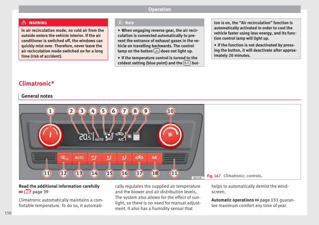
Operation
WARNING
In air recirculation mode, no cold air from theoutside enters the vehicle interior. If the airconditioner is switched off, the windows canquickly mist over. Therefore, never leave theair recirculation mode switched on for a longtime (risk of accident).
Note
● When engaging reverse gear, the air recir-culation is connected automatically to pre-vent the entrance of exhaust gases in the ve-hicle on travelling backwards. The controllamp on the button does not light up.
● If the temperature control is turned to thecoldest setting (blue point) and the A/C but-
ton is on, the “Air recirculation” function isautomatically activated in order to cool thevehicle faster using less energy, and its func-tion control lamp will light up.
● If the function is not deactivated by press-ing the button, it will deactivate after approx-imately 20 minutes.
Climatronic*
General notes
Fig. 167 Climatronic: controls.
Read the additional information carefully››› page 39
Climatronic automatically maintains a com-fortable temperature. To do so, it automati-
cally regulates the supplied air temperatureand the blower and air distribution levels.The system also allows for the effect of sun-light, so there is no need for manual adjust-ment. It also has a humidity sensor that
helps to automatically demist the wind-screen.
Automatic operations ››› page 151 guaran-tee maximum comfort any time of year.
150

Air conditioning
Climatronic description
Cooling only works if the following conditionsare met:
● The engine is running
● the outside temperature is above +2°C(+36°F);
● A/C 18 ››› Fig. 167 switched on.
Starting the Climatronic
The corresponding function will be switchedon when a button is pressed, turning on theair conditioniNG if it was switched off, withthe exception of button 17 ››› Fig. 167 (recir-culation)
Switching off the Climatronic
● Turn control 10 to the left until the seg-ments of column 9 ››› Fig. 167 switch off.
● After 1 second has elapsed, turn the controlagain to switch off the display.
In order to ensure engines subject to heavyloads are cooled, the air conditioning com-pressor is switched off in the event of highcoolant temperatures.
Recommended setting for all seasons of theyear
● Set the required temperature. We recom-mend +22 °C (72°F).
● Press the AUTO button 13 ››› Fig. 167.
● Adjust vents 3 and 4 ››› page 146 so thatthe air flow is directed slightly upwards.
Change between degrees Centigrade and de-grees Fahrenheit
Keep the AUTO and A/C ››› Fig. 167 buttonsheld down for 2 seconds at the same time.The data is displayed on the screen in theunits required.
Note
● A visit to the specialised service once ayear is recommended to clean the Climatronicsystem.
● The interior temperature sensor 11
››› Fig. 167 is at the bottom. Do not cover itwith stickers or the like, as this could have anegative effect on Climatronic operations.
Automatic mode
Automatic mode is used to maintain a con-stant temperature and demist the windowsinside the vehicle.
Switching on automatic mode
● Set the interior temperature between +16°C(+64°F) and +29°C (+84°F).
● Adjust vents 3 and 4 ››› page 146 so thatthe air flow is directed slightly upwards.
● Press the AUTO button 13 ››› Fig. 167 andAUTO displayed on the screen.
Automatic mode is switched off by pressingthe air distribution buttons or increasing ordecreasing the blower speed. However, thetemperature remains regulated.
Adjusting the temperature
● When you switch on the ignition, control 1
››› Fig. 167 can be used to set the required in-terior temperature.
It is possible to select interior temperaturesfrom +16°C (+64°F) to +29°C (+84°F). In thisrange the temperature is regulated automati-cally. If a temperature below +16°C (+64°F) isselected, “LO” is displayed on the screen. If atemperature above +29°C (+84°F) is selected,“HI” is displayed on the screen. At both ex-tremes, Climatronic works at maximum cool-ing or heating power, respectively. The tem-perature is not regulated.
In the event of prolonged, irregular distribu-tion of the air flow from the outlets (particu-larly the footwells) and significant differen-ces in temperature, e.g. on leaving the vehi-cle, sensitive people may catch cold.
151
Tech
nica
l dat
aA
dvic
eO
pera
tion
Emer
genc
ies
Saf
ety

Operation
Air recirculation
Air recirculation prevents unpleasant smells,e.g. when passing through a tunnel or inqueuing traffic, from entering the interior.
Switching on air recirculation mode
● Press button 17 ››› Fig. 167 and the symbol is displayed on the screen.
Switching off air recirculation mode
● Press button 17 ››› Fig. 167 and the symbol disappears from the screen.
WARNING
Read and observe the safety warnings ››› inGeneral notes on page 144.
Note
If air recirculation mode remains on for 15 mi-nutes, the symbol will start to flash onthe screen to indicate prolonged air recircula-tion. If air recirculation is not switched off,the symbol will continue to flash for about 5minutes.
Blower selection
Climatronic automatically regulates blowerspeed according to the interior temperature.
It is possible, however, to set the blowerspeed to suit requirements.
● Turn control 10 ››› Fig. 167 counter-clock-wise (to lower the speed) or clockwise (to in-crease the speed).
Climatronic will switch off when the blowerswitches off.
WARNING
Read and observe the safety warnings ››› inGeneral notes on page 144.
Windscreen defrost
Switching on windscreen defrosting
● Press the button 12 ››› Fig. 167.
Switching off windscreen defrosting
● Press button 12 ››› Fig. 167 severaltimes or press the AUTO button.
The temperature is regulated automatically.The air output is increased from vents 1 and2 ››› page 146.
Driving
Address
Introduction
The power steering is not hydraulic but elec-tromechanical. The advantage of this steer-ing is that it foes not need flexible hydraulicpipes, hydraulic oil, pump, filter or otherparts. The electromechanical system savesfuel. Whereas a hydraulic system needs con-tinuous oil pressure, electromechanicalsteering only needs power when it is used.
In vehicles with electromechanical steering,the assisted steering function automaticallyadjusts according to vehicle speed, steeringwheel torque and wheel orientation. Thepower steering only works when the engineis running.
WARNING
If the power steering does not work, you willneed much more strength to turn the wheel.This has a considerable effect on vehiclesafety.
● The power steering only works when theengine is running.
● Never allow the vehicle to move when theengine is switched off.
● Never remove the key from the ignitionwhile the vehicle is moving. The steering lock
152

Driving
could be engaged and vehicle steering wouldnot work.
Note
The ignition of the vehicle being towed mustbe switched on to prevent the steering wheelfrom locking and also to allow the use of theturn signals, horn, windscreen wipers andwashers.
Information relating to different vehi-cle processes.
In order to make the vehicle more difficult tosteal, you should always lock the steering be-fore leaving the vehicle.
Mechanical steering lock
The steering column is locked when the keyis removed from the ignition lock and the ve-hicle is stationary.
Activating the steering lock
● Park the vehicle ››› page 156.
● Remove the ignition key.
● Turn the steering wheel slightly until thesteering lock has engaged.
Deactivating the steering lock
● Turn the steering wheel slightly to releasethe lock.
● Insert the key in the ignition lock.
● Hold the steering wheel in this positionand switch on the ignition.
Electromechanical steering
In vehicles with electromechanical steering,the assisted steering function automaticallyadjusts according to vehicle speed, steeringwheel torque and wheel orientation. Thepower steering only works when the engineis running.
You should take into account that you willneed considerably more power than normalto steer the vehicle if the power steering isnot working correctly or at all.
Power-assisted steering
Power-assisted steering helps the driver incritical situations. In counter-steering, it as-sists by applying additional torque ››› .
WARNING
Power-assisted steering, together with theESC, helps the driver to control vehicle steer-ing in critical situations. However, the driveris ultimately responsible for steering the ve-hicle at all times. Power-assisted steeringdoes not remove this responsibility.
Starting and stopping the en-gine
Ignition key positions
Fig. 168 Ignition key positions.
Read the additional information carefully››› page 20
Ignition switched off, steering lock 1
In this position ››› Fig. 168, the ignition andthe engine are OFF and the steering may belocked.
For the Steering lock to operate without theignition key, turn the steering wheel until itlocks with an audible sound. You should al-ways lock the steering wheel when you leaveyour vehicle. This will help prevent vehicletheft ››› . »
153
Tech
nica
l dat
aA
dvic
eO
pera
tion
Emer
genc
ies
Saf
ety
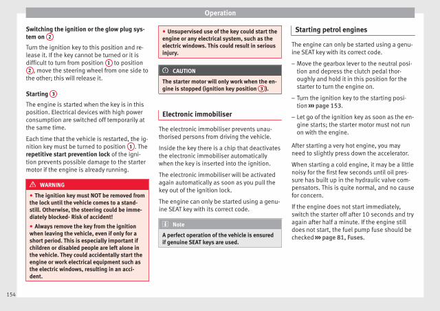
Operation
Switching the ignition or the glow plug sys-tem on 2
Turn the ignition key to this position and re-lease it. If the key cannot be turned or it isdifficult to turn from position 1 to position
2 , move the steering wheel from one side tothe other; this will release it.
Starting 3
The engine is started when the key is in thisposition. Electrical devices with high powerconsumption are switched off temporarily atthe same time.
Each time that the vehicle is restarted, the ig-nition key must be turned to position 1 . Therepetitive start prevention lock of the igni-tion prevents possible damage to the startermotor if the engine is already running.
WARNING
● The ignition key must NOT be removed fromthe lock until the vehicle comes to a stand-still. Otherwise, the steering could be imme-diately blocked- Risk of accident!
● Always remove the key from the ignitionwhen leaving the vehicle, even if only for ashort period. This is especially important ifchildren or disabled people are left alone inthe vehicle. They could accidentally start theengine or work electrical equipment such asthe electric windows, resulting in an acci-dent.
● Unsupervised use of the key could start theengine or any electrical system, such as theelectric windows. This could result in seriousinjury.
CAUTION
The starter motor will only work when the en-gine is stopped (ignition key position 3 ).
Electronic immobiliser
The electronic immobiliser prevents unau-thorised persons from driving the vehicle.
Inside the key there is a chip that deactivatesthe electronic immobiliser automaticallywhen the key is inserted into the ignition.
The electronic immobiliser will be activatedagain automatically as soon as you pull thekey out of the ignition lock.
The engine can only be started using a genu-ine SEAT key with its correct code.
Note
A perfect operation of the vehicle is ensuredif genuine SEAT keys are used.
Starting petrol engines
The engine can only be started using a genu-ine SEAT key with its correct code.
– Move the gearbox lever to the neutral posi-tion and depress the clutch pedal thor-oughly and hold it in this position for thestarter to turn the engine on.
– Turn the ignition key to the starting posi-tion ››› page 153.
– Let go of the ignition key as soon as the en-gine starts; the starter motor must not runon with the engine.
After starting a very hot engine, you mayneed to slightly press down the accelerator.
When starting a cold engine, it may be a littlenoisy for the first few seconds until oil pres-sure has built up in the hydraulic valve com-pensators. This is quite normal, and no causefor concern.
If the engine does not start immediately,switch the starter off after 10 seconds and tryagain after half a minute. If the engine stilldoes not start, the fuel pump fuse should bechecked ››› page 81, Fuses.
154

Driving
WARNING
● Never start or run the engine in unventila-ted or closed rooms. The exhaust gases con-tain carbon monoxide, an odourless and col-ourless poisonous gas. Risk of fatal acci-dents. Carbon monoxide can cause loss ofconsciousness and result in death.
● Never leave the vehicle unattended if theengine is running.
● Never use “cold start sprays”, they couldexplode or cause the engine to run at highrevs. Risk of injury.
CAUTION
● When the engine is cold, you should avoidhigh engine speeds, driving at full throttleand over-loading the engine. Risk of enginedamage.
● The vehicle should not be pushed or towedmore than 50 metres to start the engine. Un-burnt fuel could enter the catalytic converterand damage it.
● Before attempting to push-start or tow a ve-hicle in order to start it, you should first try tostart it using the battery of another vehicle.Please observe and follow the notes on the››› page 52, How to jump start.
For the sake of the environment
Do not warm-up the engine by running theengine with the vehicle stationary. Start offimmediately, driving gently. This helps the
engine reach operating temperature fasterand reduces emissions.
Starting diesel engines
The engine can only be started using a genu-ine SEAT key with its correct code.
– Move the gearbox lever to the neutral posi-tion and depress the clutch pedal thor-oughly and hold it in this position for thestarter to turn the engine on.
– Turn the ignition key to position ››› Fig. 1682 . The warning lamp will light for en-
gine pre-heating.
– When the lamp turns off, turn the ignitionkey to position 3 to start the engine. Donot press the accelerator.
– Release the ignition key as soon as the en-gine starts. The starter motor should notturn at the same time.
When starting a cold engine, it may be a littlenoisy for the first few seconds until oil pres-sure has built up in the hydraulic valve com-pensators. This is quite normal, and no causefor concern.
If there are problems starting the engine, seethe ››› page 52.
Glow plug system for the diesel engine
To avoid unnecessary discharging of the bat-tery, do not use any other major electricalequipment while the glow plugs are pre-heat-ing.
Start the engine as soon as the glow plugwarning lamp goes out.
Starting a diesel engine after the fuel tankhas been completely run dry
If the fuel tank has been completely run dry,it may take longer than normal (up to one mi-nute) to start a diesel engine after refuelling.This is because the fuel system must elimi-nate air first.
WARNING
Observe the safety warnings ››› in Startingpetrol engines on page 155.
CAUTION
● When the engine is cold, you should avoidhigh engine speeds, driving at full throttleand over-loading the engine. Risk of enginedamage.
● The vehicle should not be pushed or towedmore than 50 metres to start the engine. Un-burnt fuel could enter the catalytic converterand damage it.
● Before attempting to push-start or tow a ve-hicle in order to start it, you should first try to »
155
Tech
nica
l dat
aA
dvic
eO
pera
tion
Emer
genc
ies
Saf
ety

Operation
start it using the battery of another vehicle.Please observe and follow the notes on the››› page 52, How to jump start.
For the sake of the environment
Do not warm-up the engine by running theengine with the vehicle stationary. Youshould drive off as soon as you start the en-gine. This helps the engine reach operatingtemperature faster and reduces emissions.
Switching off the engine
– Stop the vehicle.
– Turn the ignition key to position ››› Fig. 1681 .
After switching the engine off, the radiatorfan may run on for up to 10 minutes. It is alsopossible that the fan turns itself on oncemore if the coolant temperature increasesdue to the heat accumulated in the enginecompartment or due to its prolonged expo-sure to solar radiation.
WARNING
● Never switch the engine off until the vehi-cle is completely stationary.
● The brake servo works only when the en-gine is running. With the engine switched off,more strength is needed to brake. As normal
brake operation cannot be performed, risk ofaccidents and serious injury may exist.
● The steering lock can be immediatelyblocked once the key is removed from the ig-nition. The vehicle cannot be steered. Risk ofaccident.
● Power-assisted steering does not workwhen the engine is off, and more strength isneeded to turn the wheel.
● If the key is removed from the ignition lockthe steering lock could be engaged and vehi-cle steering would not work.
CAUTION
When the engine has been running under aheavy load for a long period, heat can accu-mulate in the engine compartment and causeengine damage. For this reason, idle the en-gine for approximately 2 minutes beforeswitching it off.
Braking and parking
Braking capacity and braking distance
The efficiency of the brakes depends directlyon the brake pad wear. This wear depends toa great extent on the conditions under whichthe vehicle is operated and the way the vehi-cle is driven. If you often drive in town, driveshort distances or have a sporty driving style,we recommend that you have the thickness
of your brake pads checked by technical serv-ices more frequently than recommended inthe Maintenance Programme.
If you drive with wet brakes, for example, af-ter crossing areas of water, on days of heavyrainfall or even after washing the car, the ef-fect of the brakes is reduced as the brakediscs are wet or even frozen (in winter): inthis case, the brakes should be “dried” bypressing the brake pedal several times.
WARNING
Longer braking distances and faults in thebrake system increase the risk of accidents.
● New brake pads must be run in and do nothave the correct friction during the first200 km. This reduced braking capacity maybe compensated for by pressing on the brakepedal a little harder, which also applies whenthe brake pads have to be changed furtheron.
● If brakes are wet or frozen, or if you aredriving on roads which have been salted,braking power may be lower than normal.
● On steep slopes, if brakes are excessivelyused, they will overheat. Before driving downa long steep slope, it is advisable to reducespeed and change down into a lower gear orrange (depending on the type of transmis-sion). Thus, make use of engine braking andrelieve the brakes.
● Never let the brakes “drag” by applyinglight pressure. Continuous braking will cause
156

Driving
the brakes to overheat and the brakingdistance will increase. Apply and then releasethe brakes alternately.
● Never let the vehicle run with the engineswitched off. The braking distance is in-creased considerably when the brake servo isnot active.
● If the brake fluid loses its viscosity and issubjected to heavy use, vapour bubbles canform in the brake system. This reduces the ef-ficiency of the brakes.
● Non-standard or damaged front spoilerscould restrict the airflow to the brakes andcause them to overheat. Before purchasingaccessories please observe the relevant in-structions ››› page 190, Modifications.
● If a brake system circuit fails, the brakingdistance will be increased considerably. Con-tact a specialised workshop immediately andavoid unnecessary journeys.
Handbrake
Fig. 169 Handbrake between the front seats.
The handbrake should be applied firmly toprevent the vehicle from accidentally rollingaway. Always apply the handbrake when youleave your vehicle and when you park.
Applying the handbrake
– Pull the handbrake lever up firmly››› Fig. 169.
Releasing the handbrake
– Pull the lever up slightly and press the re-lease knob in the direction of the arrow››› Fig. 169 and guide the handbrake leverdown fully ››› .
Always pull the handbrake all the way up, sothere is less risk of driving off with it still en-gaged ››› .
The handbrake warning lamp lights upwhen the handbrake is applied and the igni-tion switched on. The warning lamp turns offwhen the handbrake is released.
WARNING
● Never use the handbrake to stop the vehi-cle when it is in motion. The braking distanceis considerably longer, because braking isonly applied to the rear wheels. Risk of acci-dent!
● If the handbrake is only partially released,this will cause the rear brakes to overheat,which can impair the function of the brakesystem and could lead to an accident. This al-so causes premature wear on the rear brakepads.
CAUTION
Always apply the handbrake before you leavethe vehicle. Put it in 1st gear as well. In vehi-cles with an automatic gearbox, place thegear lever in position P.
Parking
The handbrake should always be firmly ap-plied when the vehicle is parked.
Always note the following points when park-ing the vehicle:
– Use the brake pedal to stop the vehicle. »
157
Tech
nica
l dat
aA
dvic
eO
pera
tion
Emer
genc
ies
Saf
ety

Operation
– Apply the handbrake.
– Put it in 1st gear.
– Switch the engine off and remove the keyfrom the ignition. Turn the steering wheelslightly to engage the steering lock.
– Always take you keys with you when youleave the vehicle ››› .
Additional notes on parking the vehicle ongradients:
Turn the steering wheel so that the vehiclerolls against the kerb if it started to roll.
● If the vehicle is parked facing downhill,turn the front wheels so that they point to-wards the kerb.
● If the vehicle is parked facing uphill, turnthe front wheels so that they point away fromthe kerb.
● Secure the vehicle as usual by applying thehandbrake firmly and putting it in 1st gear.
WARNING
● Take measures to reduce the risk of injurywhen you leave your vehicle unattended.
● Never park where the hot exhaust systemcould ignite inflammable materials, such asdry grass, low bushes, spilt fuel etc.
● Never allow vehicle occupants to remain inthe vehicle when it is locked. They would beunable to open the vehicle from the inside,and could become trapped in the vehicle in
an emergency. In the event of an emergency,locked doors will delay assistance to vehicleoccupants.
● Never leave children alone in the vehicle.They could set the vehicle in motion, for ex-ample, by releasing the handbrake or thegearbox lever.
● Depending on weather conditions, it maybecome extremely hot or cold inside the vehi-cle. This can be fatal.
Hill driving assistant*
This function is only included in vehicles withESC.
The hill driving assistant helps the driver tomove off and upward on a hill when the vehi-cle is stationary.
The system maintains brake pressure for ap-proximately two seconds after the drivertakes his foot off the brake pedal to preventthe vehicle from lurching backward when it isstarted. During these 2 seconds, the driverhas enough time to release the clutch pedaland accelerate without the vehicle movingand without having to use the handbrake,making start-up easier, more comfortableand safer.
These are the basic operation conditions:
● being on a ramp or hill/slope,
● doors closed,
● vehicle completely stationary,
● engine running and foot on the brake,
● besides having a gear engaged or being inneutral for manual gear change and with theselector lever at position S, D or R for an au-tomatic gearbox.
This system is also active when reversing up-hill.
WARNING
● If you do not start the vehicle immediatelyafter taking your foot off the brake pedal, thevehicle may start to roll back under certainconditions. Depress the brake pedal or usethe hand brake immediately.
● If the engine stalls, depress the brake ped-al or use the hand brake immediately.
● When following a line of traffic uphill, if youwant to prevent the vehicle from rolling backaccidentally when starting off, hold the brakepedal down for a few seconds before startingoff.
Note
The Official Service or a specialist workshopcan tell you if your vehicle is equipped withthis system.
158

Driving
Manual gearbox
Driving with manual gearbox
Read the additional information carefully››› page 37
Certain versions of the model may include a6-speed manual gearbox, and its diagram isshown on the gearbox lever.
The reverse gear can only be engaged whenthe car is stationary. When the engine is run-ning and before engaging this gear, waitabout 6 seconds with the clutch presseddown thoroughly in order to protect the gear-box.
The reverse lights switch on when the reversegear is selected and the ignition is on.
WARNING
● When the engine is running, the vehiclewill start to move as soon as a gear is engag-ed and the clutch released.
● Never select the reverse gear when the ve-hicle is in motion. Risk of accident.
Note
● Do not rest your hand on the gear leverwhile driving. The pressure of your handcould cause premature wear on the selectorforks in the gearbox.
● When changing gear, you should alwaysdepress the clutch fully to avoid unnecessarywear and damage.
● Do not “slip” the clutch to hold the vehicleon a hill. This causes premature wear anddamage to the clutch.
● Do not leave your foot on the clutch pedal;although the pressure may seem insignifi-cant, it can cause the premature wear of theclutch plate. Use the foot rest when you donot need to change gear.
Gear-change indicator3 Valid for vehicles: with a manual gearbox
The recommended gear for saving fuel is in-dicated on the dash screen of certain vehi-cles during driving.
Display Meaning
The optimal gear is selected.
Changing to a higher gear is recommended.
Changing to a lower gear is recommended.
Information regarding the “cleanliness” ofthe diesel particulate filter
The exhaust system manager detects that thediesel particulate filter is nearly saturatedand contributes to self-cleaning by recom-mending the optimal gear. For this purpose,
it might be necessary to drive momentarilywith a high rpm ››› page 101.
WARNING
The gear change indicator is only an auxiliaryfunction and in no case should be a substi-tute for careful driving.
● The responsibility of choosing the correctgear depending on the situation (e.g. over-taking, driving up or down a slope or towing atrailer) lies with the driver.
For the sake of the environment
Selecting the correct gear can help to savefuel.
Note
The recommended gear display is switchedoff when the clutch pedal is pressed.
Automatic gearbox*
Driving programmes
Read the additional information carefully››› page 38
The automatic gearbox has got two gearboxprogrammes. »
159
Tech
nica
l dat
aA
dvic
eO
pera
tion
Emer
genc
ies
Saf
ety

Operation
Selecting the normal programme
– Put the selector lever into position D.
Selecting the sport programme
– Put the selector lever into position S.
If you select the normal programme, D, youwill drive in the economy mode, i.e. the pro-gramme is designed to reduce fuel consump-tion. The gearbox changes up into a highergear as soon as possible and down into alower gear as late as possible.
If you select the sport programme, S, you willdrive in a sporty mode, i.e. a programme inwhich shifts into high gears are postponed inorder to use the full power of the engine.
Selector lever positions
Read the additional information carefully››› page 38
Selector lever positions
The selected gear is displayed on the side ofthe selector lever and on the instrument pan-el display. The currently selected gear for theautomatic gearbox will also be shown on thedisplay.
Tiptronic gear indicator
If the automatic gearbox is shifted manually,the selected gears are shown on the screen.
P - parking lock
When the selector lever is in this position,the driven wheels are locked mechanically.
Position P on the lever must only be selectedif the vehicle is stationary.
To move selector lever from position P, thelocking button on the selector lever handlemust be pressed and the brake pedal de-pressed at the same time while the ignition isswitched on.
To put the selector lever in position P, simplypress the lock button down and, if necessary,depress the brake pedal down.
R - Reverse gear
The reverse gear is engaged in this position.
Reverse gear must be engaged only when thevehicle is stationary and the engine is idling.
To move the selector lever to position R,press the lock button down and, at the sametime, press the brake pedal down, with theignition switched on.
With the selector lever in position R and theignition switched on the following occurs:
● Reverse lights light up.
● The air conditioner automatically changesthe air recirculation mode.
● The wiper starts if the windscreen washer ison.
● The parking distance warning system*switches on.
N - Neutral (idling)
If this position is selected, the gearbox is inneutral. Power is not transmitted to thewheels and the engine does not have a brak-ing function.
Never use the N position to drive down a longhill. There is no engine braking and thebrakes are subjected to excessive stain.
You could damage the automatic gearbox ifyou drive down hills with the gearbox lever inposition N and the engine switched off.
D - Drive (forward)
In this position the gearbox automaticallychanges to a lower or higher gear, accordingto the engine's requirements, the drivingstyle and speed. The braking effect of the en-gine when driving downhill is very limitedwhen the selector is in this position. The in-strument panel display shows the selectedgear as well as the selector lever in positionD.
When travelling at speeds lower than 5 km/h(3 mph) or when the vehicle is stationary,
160
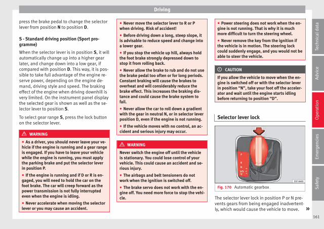
Driving
press the brake pedal to change the selectorlever from position N to position D.
S - Standard driving position (Sport pro-gramme)
When the selector lever is in position S, it willautomatically change up into a higher gearlater, and change down into a low gear, ifcompared with position D. This way, it is pos-sible to take full advantage of the engine re-serve power, depending on the engine de-mand, driving style and speed. The brakingeffect of the engine when driving downhill isvery limited. On the instrument panel displaythe selected gear is shown as well as the se-lector lever to position S.
To select gear range S, press the lock buttonon the selector lever.
WARNING
● As a driver, you should never leave your ve-hicle if the engine is running and a gear rangeis engaged. If you have to leave your vehiclewhile the engine is running, you must applythe parking brake and put the selector leverin position P.
● If the engine is running and if D or R is en-gaged, you will need to hold the car on thefoot brake. The car will creep forward as thepower transmission is not fully interruptedeven when the engine is idling.
● Never accelerate when moving the selectorlever or you may cause an accident.
● Never move the selector lever to R or Pwhen driving. Risk of accident!
● Before driving down a long, steep slope, itis advisable to reduce speed and change intoa lower gear.
● If you stop the vehicle up hill, always holdthe foot brake strongly depressed down tostop it from rolling back.
● Never allow the brake to rub and do not usethe brake pedal too often or for long periods.Constant braking will cause the brakes tooverheat and will considerably reduce thebrake effect. This increases the braking dis-tance and could cause the brake system tofail.
● Never allow the car to roll down a gradientwith the gear in neutral N, or in selector leverposition D, even if the engine is not running.
● If the vehicle moves with no control, an ac-cident and serious injury may occur.
WARNING
Never switch the engine off until the vehicleis stationary. You could lose control of yourvehicle. This could cause an accident and se-rious injury.
● The airbags and belt tensioners do notwork when the ignition is switched off.
● The brake servo does not work with the en-gine off. You need more force to stop the vehi-cle.
● Power steering does not work when the en-gine is not running. That is why it is muchmore difficult to turn the steering wheel.
● Never remove the key from the ignition ifthe vehicle is in motion. The steering lockcould suddenly engage, and you would not beable to steer the vehicle.
CAUTION
If you allow the vehicle to move when the en-gine is switched off or with the selector leverin position “N”, take your foot off the acceler-ator and wait until the engine starts idlingbefore returning to position “D”.
Selector lever lock
Fig. 170 Automatic gearbox
The selector lever lock in position P or N pre-vents gears from being engaged inadvertent-ly, which would cause the vehicle to move. »
161
Tech
nica
l dat
aA
dvic
eO
pera
tion
Emer
genc
ies
Saf
ety

Operation
The selector lever lock is released as follows:
– Switch the ignition on.
– Press and hold the brake pedal and pressthe selector lever lock on the left of the se-lector lever at the same time ››› Fig. 170.
The warning lamp on the instrument panellights up when the brake pedal should be ap-plied. This is essential when the selector lev-er is taken from the P or N positions.
Level lock only engages with the vehicle sta-tionary at a speed of up to 5 km/h (3 mph).At speeds of over 5 km/h (3 mph) the selec-tor lever lock is automatically deactivated inposition N.
The selector lever lock is not engaged if theselector lever is moved quickly through posi-tion N (e.g. when shifting from R to D). Thismakes it possible, for instance, to “rock” thevehicle backwards and forwards if it is stuckin snow or mud. The selector lever lock en-gages automatically if the brake pedal is notdepressed and the lever is in position N formore than about 1second.
Selecting gears manually with Tip-tronic mode*
Fig. 171 Changing gear with Tiptronic.
Fig. 172 Steering wheel with paddle leversfor automatic gearbox.
The Tiptronic system allows the driver to se-lect gears manually.
Changing gear with the selector lever
– Press the selector lever from position D tothe right into the tiptronic selector gate.
– Lightly press the selector lever forward››› Fig. 171 + to change up to a highergear.
– Lightly press the selector lever backward››› Fig. 171 - to change down to a lowergear.
Changing gear with the steering wheel pad-dle levers*
– Press the right paddle lever + towards thesteering wheel to change up ››› Fig. 172.
– Press the left paddle lever - towards thesteering wheel to change down ››› Fig. 172.
Using the paddle levers on the steeringwheel, you can access manual driving moderegardless of the pre-selected driving mode.
General information about driving in tiptron-ic mode
When accelerating, the automatic gearbox /DSG automatic gearbox goes into a highergear a little before the engine reaches itsmaximum permitted revolutions.
If a lower gear is selected, the automaticgearbox / DSG automatic gearbox will onlychange down when the engine cannot goover its maximum permitted revolutions.
162

Driving
If “tiptronic” is selected whilst the vehicle isin motion and the automatic gearbox / DSGautomatic gearbox is in third gear and selec-tor lever position D, “tiptronic” mode willthen also be in third gear.
Changing gears in the normal or sport pro-gramme using the steering wheel paddle lev-ers
If the paddle levers ››› Fig. 172 are used inthe normal or sport programme, the systemswitches temporarily to “tiptronic” mode. Toexit “Tiptronic” mode again, press the rightpaddle lever + towards the steering wheelfor approximately one second. You will alsoleave “tiptronic” mode if the paddle leversare not moved for a certain time.
Note
● The gear paddle levers on the steeringwheel can be operated with the selector leverin any position and with the vehicle in mo-tion.
Driving tips
The gearbox changes gear ratios automatical-ly as the vehicle moves.
Starting
– Start the engine with the selector lever inposition P or N.
Driving
– Press and hold the brake pedal.
– Holding down the lock button (button onthe selector lever), select R or D.
– Release the lever and wait a little for thegearbox to engage the gear (a slight move-ment can be felt).
– Release the brake and press the accelerator››› in Selector lever positions onpage 161.
Stopping briefly
– If stopping for a short time, keep the vehi-cle stationary by pressing the foot brakehard to prevent the vehicle moving back-wards on a slope or “creeping” forwards,e.g. at traffic lights. The selector lever doesnot need to be put into the positions P or Nfor this.
– Do not press the accelerator.
Parking
– Press and hold the brake pedal until the ve-hicle comes to a standstill ››› in Selectorlever positions on page 161.
– Apply the handbrake.
– By pressing the lock button down, movethe selector lever to P and release the lockbutton.
Driving up and down hills
– Press the selector lever from position “D”to the right into the tiptronic selector gate.
– Lightly press the selector lever back tochange down.
Holding the car on a hill
– The brake must be always pressed down toprevent the vehicle from “rolling back-wards” ››› in Selector lever positions onpage 161. Do not try to prevent the vehiclefrom “rolling backwards” by increasing theengine speed while a range of gears is se-lected.
Starting the vehicle up hills
– Apply the handbrake.
– With a selected gear, accelerate slowly andat the same time, release the handbrake.
The steeper the slope, the lower the neededgear. This increases the braking effect of theengine. For example, when driving down avery steep slope in third gear. If the enginebrake effect is not enough, the vehicle willspeed up. The automatic gearbox automati-cally changes up to prevent the engine over-revving. Use the foot brake to reduce speedand change into 3rd gear using Tiptronic*››› in Selector lever positions on page 161.
Your vehicle has an automatic interlockwhich prevents the selector lever from being »
163
Tech
nica
l dat
aA
dvic
eO
pera
tion
Emer
genc
ies
Saf
ety

Operation
put into a position for driving forwards or inreverse from positions P or N if the brakepedal is not depressed.
The ignition key cannot be removed unlessthe selector lever is in position P.
Control lamp “Pressing brake pedal”
When the warning lamp next to the selectorlever lights up, press the brake pedal. This isnecessary when the automatic gearbox selec-tor lever is moved out of positions P or N. Atext message or instructions to perform nec-essary operations may appear on the instru-ment panel.
CAUTION
● If you stop the vehicle up hills, do not at-tempt to stop it from rolling back by depress-ing the accelerator when a gear has been se-lected. Otherwise, the automatic gearboxmay overheat causing damage. Pull the hand-brake up or fully depress the brake pedal toprevent the vehicle from rolling away.
● If you allow the vehicle to roll when the en-gine is not running, or with the selector leverin position N, a lack of lubrication in the auto-matic gearbox will damage it.
Kick-down feature
This feature allows maximum acceleration.
If you press the accelerator down thoroughly,the gearbox automatically changes down, de-pending on speed and engine speed, into alower gear to take full advantage of give thevehicle maximum acceleration.
The gearbox does not change gear until theengine reaches the maximum determined en-gine speed for the gear.
WARNING
You could lose control of the vehicle if you ac-celerate on slippery road surfaces. Risk of se-rious injury.
● Be particularly careful when using the kick-down features on slippery road surfaces. Witha fast acceleration, the vehicle could losetraction and skid.
● You should use the kick-down feature onlywhen traffic and weather conditions allow itto be used safely.
Gearbox malfunctions
Gearbox: Fault! Stop the ve-hicle and place the lever in theposition P.
There is a fault in the gearbox. Stop the vehi-cle in a safe place and do not continue driv-ing. Seek specialist assistance.
Gearbox: System fault! Youmay continue driving.
Have the fault corrected by a specialisedworkshop without delay.
Gearbox: System fault! Youcan continue driving with re-strictions. Reverse gear disa‐bled
Take the vehicle to a specialised workshopand have the fault repaired without delay.
Gearbox: System fault! Youcan continue driving in D untilswitching off the engine
Stop the vehicle in a safe place well awayfrom moving traffic. Seek specialist assis-tance.
Gearbox: too hot. Adapt yourdriving accordingly
Continue driving at moderate speeds. Whenthe warning lamp switches off, you can con-tinue driving in a normal manner.
Gearbox: press the brake andengage a gear again.
If the fault was caused by a gearbox with ahigh temperature, this driver message will bedisplayed when the gearbox has cooledagain.
164

Driving
Run-in and economical driving
Running in a new engine
The engine needs to be run in over the first1,500 km.
Up to 1000 kilometres
– Do not drive at speeds of more than 2/3the maximum speed.
– Do not accelerate hard.
– Avoid high engine revolutions.
– Do not tow a trailer.
From 1000 to 1500 kilometres (600 to 900miles)
– Speeds can be gradually increased to themaximum road speed or maximum permis-sible engine speed (rpm).
During its first few hours of running, the in-ternal friction in the engine is greater thanlater on, when all the moving parts have bed-ded in.
For the sake of the environment
If the engine is run in gently, its life will be in-creased and its oil consumption reduced.
Tyre and brake pad run-in
New tyres should be run-in carefully for thefirst 500 km (300 miles). New brake padsshould be run-in carefully for the first200 km.
During the first 200 km, you can compensatefor the reduced braking effect by applyingmore pressure to the brake pedal. In case ofa sharp braking, the braking distance will belonger with new brake pads than with brakepads which have been run-in.
WARNING
● At first, new tyres do not give maximumgrip, and require running-in. This may causean accident. Drive particularly carefully in thefirst 500 km.
● New brake pads must be “run in” and donot have the correct friction properties duringthe first 200 km. However, the reduced brak-ing capacity may be compensated by press-ing on the brake pedal a little harder.
Environmental compatibility
Environmental protection is a top priority inthe design, choice of materials and manufac-ture of your new SEAT.
Constructive measures to encourage recy-cling
● Joints and connections designed for easydismantling
● Modular construction to facilitate disman-tling
● Increased use of single-grade materials.
● Plastic parts and elastomers are marked inaccordance with ISO 1043, ISO 11469 andISO 1629.
Choice of materials
● Use of recycled materials.
● Use of compatible plastics in the same partif its components are not easily separated.
● Use of recycled materials and/or materialsoriginating from renewable sources.
● Reduction of volatile components, includ-ing odour, in plastic materials.
● Use of CFC-free coolants.
Ban on heavy metals, with the exceptionsdictated by law (Annex II of ELV Directive2000/53/EC): cadmium, lead, mercury, hexa-valent chromium.
Manufacturing methods
● Reduction of the quantity of thinner in theprotective wax for cavities.
● Use of plastic film as protection during ve-hicle transport. »
165
Tech
nica
l dat
aA
dvic
eO
pera
tion
Emer
genc
ies
Saf
ety

Operation
● Use of solvent-free adhesives.
● Use of CFC-free coolants in cooling sys-tems.
● Recycling and energy recovery from resi-dues (RDF).
● Improvement in the quality of waste water.
● Use of systems for the recovery of residualheat (thermal recovery, enthalpy wheels,etc.).
● The use of water-soluble paints.
Catalytic converter
To maintain the useful life of the catalyticconverter
– Use only unleaded petrol with petrol en-gines, as lead damages the catalytic con-verter.
– Do not let the fuel get too low in the tank.
– For engine oil changes, do not replenishwith too much engine oil ››› page 206, Top-ping up engine oil.
– Never tow the vehicle to start it, use jumpleads if necessary ››› page 52.
If you notice misfiring, uneven running orloss of power when the vehicle is moving, re-duce speed immediately and have the vehi-cle inspected at the nearest specialisedworkshop. In general, the exhaust warning
lamp will light up when any of the describedsymptoms occur ››› page 100. If this hap-pens, unburnt fuel can enter the exhaust sys-tem and escape into the environment. Thecatalytic converter can also be damaged byoverheating.
WARNING
The catalytic converter reaches very hightemperatures! Risk of fire!
● Never park where the catalytic convertercould come into contact with dry grass orflammable materials under the vehicle.
● Do not apply additional underseal or anti-corrosion coatings to the exhaust pipes, cata-lytic converter or the heat shields on the ex-haust system. These materials could catchfire when the vehicle is being driven.
CAUTION
Never run the fuel tank completely dry be-cause the irregularity of the fuel supply maycause ignition problems. This allows unburntfuel to enter the exhaust system, which couldcause overheating and damage the catalyticconverter.
For the sake of the environment
Even when the emission control system isworking perfectly, there may be a smell ofsulphur from the exhaust gas under someconditions. This depends on the sulphur con-tent of the fuel used. Quite often the problem
can be solved by changing to another brandof fuel.
Diesel engine particulate filter*
Fig. 173 Vehicle data sticker on back cover ofthe Maintenance Programme.
Your vehicle is fitted with a DPF (Diesel Partic-ulate Filter) if the vehicle data sticker (backcover of the “Maintenance Programme”) liststhe code PR 7GG ››› Fig. 173.
The diesel engine particulate filter eliminatesmost of the soot from the exhaust gas sys-tem. Under normal driving conditions, the fil-ter cleans itself. If this is not possible (for ex-ample, multiple short trips) the filter will beobstructed by soot and the diesel engineparticulate filter warning lamp will light up.This does not represent a fault, it is a warningthat indicates that the filter has not beenable to regenerate automatically and that you
166

Driving
must perform a cleaning cycle, as indicatedin ››› page 101.
WARNING
● The diesel engine particulate filter mayreach extremely high temperatures; the vehi-cle should be parked so that the exhaust pipedoes not come into contact with flammablematerials underneath the vehicle. Otherwisethere is a risk of fire.
CAUTION
● Your vehicle is not designed to use biodie-sel fuel. Never, under any circumstances re-fuel with biodiesel. The use of biodiesel fuelcould damage the engine and the fuel sys-tem. The addition of biodiesel to diesel bythe diesel producer in accordance with stand-ard EN 590 is authorised and will not causedamage to the engine or the fuel system.
● Using diesel fuel with a high sulphur con-tent may significantly reduce the useful life ofthe diesel particulate filter. Your TechnicalService will be able to tell you which coun-tries have diesel with a high sulphur content.
Ecological and environmentally-friendly driving
Fuel consumption, environmental pollutionand wear to the engine, brakes and tyres de-pends in large part on your driving style. Byadopting an economical driving style and an-
ticipating the traffic situation ahead, you caneasily reduce fuel consumption by 10-15%.Some tips on how to help you reduce pollu-tion while saving money are listed below.
Active cylinder management (ACT®)
Depending on the equipment, the vehiclemay have active cylinder management(ACT®).
The active cylinder management (ACT®) mayautomatically deactivate some of the enginecylinders if the driving situation does not re-quire too much power. When it is switchedoff, no fuel is injected into these cylinders,hence total fuel consumption may be re-duced. The number of active cylinders can beseen on the instrument panel display››› page 30.
Drive anticipating the traffic situation
A vehicle uses most fuel when accelerating.When you anticipate situations, you have tobrake less often and, thus, accelerate less. Ifit is possible, let the vehicle roll with a gearengaged, for example, if you see a red lightahead. The braking effect achieved in thisway helps to reduce the wear of brakes andtyres; emissions and fuel consumption arereduced to zero (disconnection due to iner-tia).
Change gear early to save energy
An effective way of saving fuel is to changeup quickly through the gears. Running theengine at high rpm in the lower gears usesan unnecessary amount of fuel.
Manual gearbox: shift up from first to secondgear as soon as possible. We recommendthat, whenever possible, you change to ahigher gear upon reaching 2000 rpm. Followthe “recommended gear” indication that ap-pears on the instrument panel ››› page 159.
Avoid driving at high speed
We advise you not to drive at the top speedpermitted by the vehicle. Fuel consumption,exhaust emissions and noise levels all in-crease very rapidly at higher speeds. Drivingat moderate speeds will help to save fuel.
Avoid idling
It is worthwhile switching off the enginewhen waiting in a traffic jam, at level cross-ings or at traffic lights with a long red phase.The fuel saved after only 30 - 40 seconds isgreater than the amount of fuel needed to re-start the engine.
The engine takes a long time to warm upwhen it is idling. Mechanical wear and pollu-tant emissions are also especially high dur-ing this initial warm-up phase. It is thereforebest to drive off immediately after starting »
167
Tech
nica
l dat
aA
dvic
eO
pera
tion
Emer
genc
ies
Saf
ety

Operation
the engine. Avoid running the engine at highspeed.
Periodic maintenance
Periodic maintenance work guarantees that,before beginning a journey, you will not con-sume more than the required amount of fuel.A well-serviced engine gives you the benefitof improved fuel efficiency as well as maxi-mum reliability and an enhanced resale val-ue.
A badly serviced engine can consume up to10% more fuel than necessary.
Avoid short journeys
To reduce the consumption and emission ofpolluting exhaust gases, the engine and theexhaust gas filtration systems should reachthe optimum operating temperature.
With the engine cold, fuel consumption isproportionally higher. The engine does notwarm up and fuel consumption does not nor-malise until having driven approximately fourkilometres (2.5 miles). This is why we recom-mend avoiding short trips whenever possi-ble.
Maintain the correct tyre pressures
Bear in mind that keeping the tyres at an ad-equate pressure saves fuel. If the tyre pres-sure is just one bar (14.5 psi/100 kPa) toolow, fuel consumption can increase by as
much as 5%. Due to the greater rolling resist-ance, under-inflation also increases tyre wearwear and impairs handling.
The tyre pressures should always be checkedwhen the tyres are cold.
Do not use winter tyres all year round as theyincrease fuel consumption by up to 10%.
Avoid unnecessary weight
Given that every kilo of extra weight will in-crease the fuel consumption, it is advisableto always check the luggage compartment tomake sure that no unnecessary loads are be-ing transported.
A roof rack is often left in place for the sakeof convenience, even when it is no longerneeded. At a speed of 100 km/h (62 mph)and 120 km/h (75 mph) your vehicle will useabout 12% more fuel as a result of the extrawind resistance caused by the roof rack evenwhen it is not in use.
Save electricity
The engine activates the alternator, whichproduces electricity. With the need for elec-tricity, fuel consumption also increases. Be-cause of this, always turn off electrical devi-ces when you do not need them. Examples ofdevices that use a lot of electricity are: theblower at high speeds, the rear window heat-ing or the seat heaters*.
Note
● If your vehicle has Start-Stop, it is not rec-ommended that you switch this function off.
● It is recommended that you close the win-dows when driving at more than 60 km/h(37 mph)
● Do not drive with your foot resting on theclutch pedal,, as the pressure can make theplate spin, more fuel will be used and it canburn the clutch plate lining, causing a seriousfault.
● Do not hold the car on a hill with the clutch,use the foot brake or hand brake, using thelatter to start. The fuel consumption will belower and you will prevent the clutch platefrom being damaged.
● On descents, use the engine brake, chang-ing to the gear that is more suitable for theslope. Fuel consumption will be “zero” andthe brakes will not suffer.
Driving abroad
To drive abroad, the following must be takeninto consideration:
● For vehicles fitted with a catalytic converterensure that unleaded petrol is available forthe journey. See the chapter “Refuelling”. Au-tomobile organisations will have informationabout service station networks selling unlea-ded fuel.
168

Driver assistance systems
● In some countries, it is possible that yourcar model is not sold, and therefore somespare parts are not available or the technicalservices may only be able to carry out limitedrepairs.
SEAT importers and distributors will gladlyprovide information about the technical prep-aration that your vehicle requires and alsoabout necessary maintenance and repairpossibilities.
Adhesive strips for headlights
In countries where vehicles drive on the otherside of the road to your home country, theasymmetric dipped beam may dazzle driversof oncoming vehicles.
To prevent dazzling, you must apply stickersto certain parts of the headlight lenses. Fur-ther information is available at any TechnicalService.
In vehicles with adaptive headlights, the ro-tation system must previously be disconnec-ted. To do this, please go to a specialisedworkshop.
Driver assistance systems
Braking and stability systems
Connecting/disconnecting ESC andASR
The ESC is switched on automatically whenthe engine is started, and only works whenthe engine is running and includes the ABS,EDS and ASR systems.
The ASR and ESC function should only beswitched off in situations in which traction isinsufficient, among others:
● When driving in deep snow or on surfacesthat are not very firm.
● To “free” the vehicle if it gets stuck.
Then switch the ASR and ESC function backon.
Depending on finishes and versions, it ispossible either to disconnect only the ASR orelse activate ESC Sport mode.
ESC in “Sport” mode
Sport mode can be connected via the EasyConnect ››› page 107 system menu. The abili-ty of the ESC to stabilise the vehicle is limi-ted; the traction control system (ASR) be-comes disabled ››› .
The control lamp lights up. For vehicleswith a driver information system*, the driverwill be shown the electronic stabilitycontrol (ESC) option: sport.Warning! Limited stability.
Disable ESC “Sport” mode
Through the Easy Connect system menu››› page 107. The warning lamp will switchoff. For vehicles with a driver information sys-tem*, the driver will be shown the elec-tronic stability control (ESC)option: on.
Disable ASR
The Easy Connect system is used to switch offthe ASR ››› page 107. The traction control sys-tem will be disabled.
The control lamp lights up. For vehicleswith a driver information system* the driverwill be informed that ASR is disabled.
Activate ASR
The Easy Connect system ››› page 107 is usedto switch on the ASR. The traction control sys-tem will be enabled.
The control lamp switches off. For vehicleswith a driver information system* the driverwill be informed that ASR is enabled.
● Activate or deactivate the ASR or ESC func-tion in the Easy Connect system by means of »
169
Tech
nica
l dat
aA
dvic
eO
pera
tion
Emer
genc
ies
Saf
ety
Operation
the button and the function buttonsSetup and ESC System .
WARNING
You should switch on the ESC Sport mode on-ly if the traffic conditions and your drivingability allow you to do so safely: risk of skid-ding!
● With ESC in Sport mode, the stabilisingfunction will be limited to allow for a sportierdrive. The driving wheels could spin and thevehicle could skid.
Note
If the ASR is disconnected or the ESC’s Sportmode is selected, cruise control* will beswitched off.
Electronic Stability Control (ESC)*
This Electronic Stability System reduces therisk of skidding and improves the vehicle'sstability and ability to hold the road.
The Electronic Stability Control (ESC) containsthe electronic differential lock (EDL) and thetraction control system (ASR). The ESC workstogether with the ABS. Both control lampswill light up if the ESC or ABS systems arefaulty.
The ESC system is started automaticallywhen the engine is started.
The ESC system is always active and cannotbe switched off. With the Easy Connect sys-tem it is only possible to deactivate the ASRor else select Sport mode.
The ASR can be deactivated when wheel spinis desirable ››› page 172.
For example:
● When driving with snow chains.
● When driving in deep snow or on loose sur-faces.
● When the vehicle is stuck, to rock it back-wards and forwards.
Press the button to switch the ASR back onwhen you no longer need wheel spin.
Electronic Stability Control (ESC)*
The ESC reduces the risk of skidding by brak-ing the wheels individually.
The system uses the steering wheel angleand road speed to calculate the changes ofdirection desired by the driver, and constant-ly compares them with the actual behaviourof the vehicle. When irregularities occur, forexample, if the vehicle begins to skid, theESC brakes the appropriate wheel automati-cally.
The forces acting on the braked wheel bringthe vehicle back to a stable condition. If thevehicle tends to oversteer (the rear end
slides out), the system will act on the frontwheel on the outside of the turn.
WARNING
● Do not forget that the electronic stabilitycontrol ESC cannot defy the laws of physics.This should be kept in mind, particularly onslippery and wet roads and when towing atrailer.
● Always adapt your driving style to suit thecondition of the roads and the traffic situa-tion. The greater safety provided by the ESCshould not encourage you to run any risks.
CAUTION
● To ensure that the ESC works correctly, allfour wheels must be fitted with the sametyres. Any differences in the rolling radius ofthe tyres can cause the system to reduce en-gine power when this is not desired.
● Any modifications made to the vehicle (forexample, to the engine, brake system, run-ning gear or to the combination of wheelsand tyres) may affect the operation of theABS, EDL, ESC and ASR.
Electronic differential lock (EDS)*
EDL helps the vehicle to start moving, accel-erate and climb a gradient in slippery condi-tions where this may otherwise be difficult oreven impossible.
170

Driver assistance systems
It uses the ABS sensors to monitor the speedof the driven wheels. In case of an EDL fault,the warning light for ABS lights up››› page 102.
At speeds of up to approximately 80 km/h(50 mph), it is able to balance out differencesin the speed of the driven wheels of approxi-mately 100 rpm/min caused by a partiallyslippery road surface. It does this by brakingthe wheel which has lost traction and distrib-uting more driving force to the other drivenwheel via the differential.
To prevent the disc brake of the brakingwheel from overheating, the EDL cuts out au-tomatically if subjected to excessive loads.The vehicle will continue to function normallywithout EDL. For this reason, the driver is notinformed that the EDL has been switched off.
The EDL will switch on again automaticallywhen the brake has cooled down.
WARNING
● When accelerating on a slippery surface,for example on ice and snow, press the accel-erator carefully. Despite EDL, the drivenwheels may start to spin. This could impairthe vehicle's stability.
● Always adapt your driving style to suit roadconditions and the traffic situation. Do not letthe extra safety afforded by EDL tempt you in-to taking any risks when driving, this cancause accidents.
CAUTION
Modifications to the vehicle (e.g. to the en-gine, the brake system, running gear or anycomponents affecting the wheels and tyres)could affect the efficiency of the EDL››› page 190.
Hydraulic Brake Assist (HBA)*
The function (Hydraulic Brake Assist HBA) isonly included in vehicles with ESC.
In an emergency, most drivers brake in time,but not with maximum force. This results inunnecessarily long braking distances.
This is when the brake assist system comesinto action. When pressing the brake pedalrapidly, the assistant interprets it as an emer-gency. It very quickly builds up the full brakepressure so that the ABS can be activatedmore quickly and efficiently, thus reducingbraking distance.
Do not reduce the pressure on the brake ped-al, since the brake assist system switches offautomatically as soon as you release thebrake.
Automatic hazard warning lights activation
The brake lights flash automatically to indi-cate that the vehicle is braking suddenly or inan emergency situation. If the emergencybraking continues until the vehicle comes to
a standstill, the hazard warning lights willthen come on and the brake lights will re-main on permanently from that moment. Thewarning lights will automatically switch offwhen the vehicle begins to move again orwhen the "warning" light button is pressed.
WARNING
● The risk of accident is higher if you drivetoo fast, if you do not keep your distance fromthe vehicle in front, and when the road sur-face is slippery or wet. The increased acci-dent risk cannot be reduced by the brake as-sist system.
● The brake assist system cannot defy thelaws of physics. Slippery and wet roads aredangerous even with the brake assist system!Therefore, it is essential that you adjust yourspeed to suit the road and traffic conditions.Do not let the extra safety features tempt youinto taking any risks when driving.
Anti-lock brake system (ABS)
The anti-lock brake (ABS) system preventsthe wheels from locking during braking andis an important part of the vehicle's activesafety system.
How the ABS works
If one of the wheels turns too slowly in rela-tion to the vehicle's speed, and is close tolocking, the system will reduce the braking »
171
Tech
nica
l dat
aA
dvic
eO
pera
tion
Emer
genc
ies
Saf
ety

Operation
pressure to this wheel. The driver is madeaware of this control process by a pulsatingof the brake pedal and audible noise. This isa deliberate warning to the driver that one ormore of the wheels is tending to lock and theABS control function has intervened. In thissituation it is important to keep the brakepedal fully depressed so the ABS can regu-late the brake application. Do not “pump”.
If you brake hard on a slippery road surface,the best possible control is retained as thewheels do not lock.
However, ABS will not necessarily guaranteeshorter braking distances in all conditions.Braking distance could even be further if youbrake on gravel or on fresh snow on a slip-pery surface.
WARNING
● The anti-lock brake system cannot defy thelaws of physics. Slippery and wet roads aredangerous even with ABS! If you notice thatthe ABS is working (to counteract lockedwheels under braking), you should reducespeed immediately to suit the road and trafficconditions. Do not let the extra safety fea-tures tempt you into taking any risks whendriving.
● The effectiveness of ABS is also determinedby the tyres fitted ››› page 212.
● If the running gear or brake system is modi-fied, the effectiveness of the ABS could be se-verely limited.
Traction control system (ASR)*
The traction control system prevents the driv-en wheels from spinning when the vehicle isaccelerating. This system always includesABS.
Description and operation of the tractioncontrol system during acceleration (ASR
On front-wheel drive vehicles, the ASR sys-tem intervenes, reducing engine power andpreventing the driven wheels from slippingduring acceleration. The system works in theentire speed range in conjunction with ABS.If a failure occurs in the ABS, the ASR will al-so stop working.
TCS helps the car to start moving, accelerateand climb a gradient in slippery conditionswhere this may otherwise be difficult or evenimpossible.
The ASR automatically switches on when theengine is started. If necessary, it could beconnected or disconnected by means of theEasy Connect system.
When the ASR is off, the warning lamp lightsup . The ASR should normally be left on.Only in exceptional circumstances, whenwheel spin is required, can they be turned offusing the ESC button, for example:
● With compact temporary spare wheel.
● When using the snow chains.
● When driving in deep snow or on soft ter-rain.
● When the vehicle is bogged-down, to free it“by rocking it.”
The ASR should be switched on again assoon as possible.
WARNING
● Remember that not even the ASR can defythe laws of physics. This should be kept inmind, particularly on slippery and wet roadsand when towing a trailer.
● Always adapt your driving style to suit thecondition of the roads and the traffic situa-tion. The greater safety provided by the ASRshould not encourage you to run any risks.
CAUTION
● To ensure that the ASR works correctly,identical tyres should be fitted on all fourwheels. Any differences in the rolling radiusof the tyres can cause the system to reduceengine power when this is not desired.
● Any modifications made to the vehicle (forexample, to the engine, brake system, run-ning gear or to the combination of wheelsand tyres) may affect the operation of theABS and ASR.
172

Driver assistance systems
Electronic differential lock (XDS)*
When taking a curve, the driveshaft differen-tial mechanism allows the outer wheel to turnat a higher speed than the inner wheel. Inthis way, the wheel that is turning faster (out-er wheel) receives less drive torque than theinner wheel. This may mean that in certainsituations the torque delivered to the innerwheel is too high, causing the wheels tospin. On the other hand, the outer wheel isreceiving a lower drive torque than it couldtransmit. This causes an overall loss of lateralgrip on the front axle, resulting in understeeror “lengthening” of the trajectory.
The XDS system can detect and correct thiseffect via the sensors and signals of the ESC.
Via the ESC, the XDS will brake the insidewheel and counter the excess driving torqueof that wheel. This means that the driver'sdesired trajectory is much more precise.
The XDS system works in combination withthe ESC and is always active, even when ASRtraction control is disconnected or the ESC isin Sport mode.
Brake servo
The brake servo increases the pressure youapply to the brake pedal. It works only whenthe engine is running.
If the brake servo is not functioning, e.g. dueto a malfunction, or if the vehicle is beingtowed, you will have to press the brake pedalconsiderably harder to make up for the lackof servo assistance.
WARNING
The braking distance can also be affected byexternal factors.
● Never let the vehicle coast with the engineswitched off. Failure to follow this instructioncould result in an accident. The braking dis-tance is increased considerably when thebrake servo is not active.
● If the brake servo is not working, for exam-ple when the vehicle is being towed, you willhave to press the brake pedal considerablyharder than normal.
Start-Stop System*
Description and operation
The Start-Stop function stops the enginewhen the vehicle is stopped and starts it au-tomatically when required.
Vehicles with a manual gearbox
– When the vehicle is stopped, put it intoneutral and release the clutch pedal. Theengine will switch off. The warning lamp
will appear on the instrument panel dis-play.
– When the clutch pedal is pressed the en-gine will start up again. The warning lampwill switch off.
Vehicles with an automatic gearbox
– Use the foot brake to bring the vehicle to astop and keep the brake pedal presseddown with your foot. The engine will switchoff. The warning lamp will appear in thedisplay.
– When you take your foot off the brake pedalthe engine will start up again. The warninglamp will switch off.
Start-Stop function conditions
● The driver seat belt must be buckled.
● The bonnet must be closed.
● The engine must be at operating tempera-ture.
● The steering wheel must be straight.
● The vehicle must be on flat ground.
● The vehicle must not be in reverse.
● A trailer must not be connected.
● The temperature of the interior must bewithin the comfort limits ( A/C button shouldbe selected).
● The windscreen de-mist function must beoff. »
173
Tech
nica
l dat
aA
dvic
eO
pera
tion
Emer
genc
ies
Saf
ety

Operation
● If in an increase in airflow is not requested.
● The temperature must not be set to HI orLO.
● The driver door must be closed.
● The diesel particulate filter must not be inregeneration mode, for diesel engines.
● The battery charge must not be low for thenext start.
● Battery temperature must be between -1°C(+30°F) and +55°C (+131°F).
Start-Stop function interruption
In the following situations, the Start-Stopfunction will be interrupted and the enginewill automatically start:
● The vehicle starts moving.
● The brake pedal is pressed several times ina row.
● The battery has been discharged excessive-ly.
● The Start-Stop System is manually deacti-vated.
● The windscreen de-mist function is turnedon.
● The temperature of the interior exceeds thecomfort limits ( A/C button).
● If the airflow is increased by more than 3presses.
● Temperature setting HI or LO is selected.
● The engine coolant temperature is insuffi-cient.
● The alternator is faulty, for example the V-belt has ruptured.
● If any of the conditions described in theprevious section are not fulfilled.
When the engine is turned off by the Start-Stop function, this is displayed on the instru-ment panel.
If the Start-Stop system is not switched on,the warning lamp will appear on the instru-ment panel.
WARNING
Never allow the vehicle to move with the en-gine off for any reason. You could lose controlof your vehicle. This could cause an accidentand serious injury.
● The brake servo does not work with the en-gine off. You need more force to stop the vehi-cle.
● Power steering does not work when the en-gine is not running. That is why it is muchmore difficult to turn the steering wheel.
● Turn off the Start-Stop system when drivingthrough water (fording streams, etc.).
Note
● For vehicles with the Start-Stop functionand a manual gearbox, when the engine isstarted, the clutch must be pressed.
● When the conditions for the Start-Stopfunction are not fulfilled, the instrument pan-el displays the Start-Stop indicator dimmed.
● If the steering wheel is turned more than270°, it will not be possible to start the vehi-cle again. To start the vehicle, straighten thesteering wheel so that it is turned less than270°.
● There are different versions of the dashpanel; the display of indications on thescreen may differ.
Activating and deactivating the Start-Stop function
Fig. 174 The Start-Stop function button.
Every time the ignition is switched on, theStart-Stop function is automatically activa-ted.
174

Driver assistance systems
Manually deactivating the Start-Stop func-tion
– Press the ››› Fig. 174 button located onthe centre console. When the Start-Stopfunction is switched off, the warning lampcomes on.
– If the Start-Stop function is operating thenthe engine starts immediately.
Switching the Start-Stop function on manual-ly
– Press the ››› Fig. 174 button located onthe centre console. The warning lamp willswitch off.
Tiredness detection (break rec-ommendation)*
Introduction
››› table on page 2
The Tiredness detection informs the driverwhen their driving behaviour shows signs offatigue.
WARNING
Do not let the comfort afforded by the Tired-ness detection system tempt you into takingany risks when driving. Take regular breaks,
sufficient in length when making long jour-neys.
● The driver always assumes the responsibil-ity of driving to their full capacity.
● Never drive if you are tired.
● The system does not detect the tiredness ofthe driver in all circumstances. Consult the in-formation in the section ››› page 176, Systemlimitations.
● In some situations, the system may incor-rectly interpret an intended driving manoeu-vre as driver tiredness.
● No warning is given in the event of the ef-fect called microsleep!
● Please observe the indications on the in-strument panel and act as is necessary.
Note
● Tiredness detection has been developed fordriving on motorways and well paved roadsonly.
● If there is a fault in the system, have itchecked by a specialised workshop.
Function and operation
Fig. 175 On the instrument panel display:tiredness detection symbol.
Tiredness detection determines the drivingbehaviour of the driver when starting a jour-ney, making a calculation of tiredness. This isconstantly compared with the current drivingbehaviour. If the system detects that the driv-er is tired, an audible warning is given with asound and an optic warning is shown with asymbol and complementary message on theinstrument panel display ››› Fig. 175. Themessage on the instrument panel display isshown for approximately 5 seconds, and de-pending on the case, is repeated. The systemstores the last message displayed.
The message on the instrument panel displaycan be switched off by pressing the button on the windscreen wiper lever or thebutton on the multi function steeringwheel ››› page 25. »
175
Tech
nica
l dat
aA
dvic
eO
pera
tion
Emer
genc
ies
Saf
ety

Operation
The message can be recalled to the instru-ment panel display using the multifunctiondisplay ››› page 25.
Conditions of operation
Driving behaviour is only calculated onspeeds above about 65 km/h (40 mph) up toaround 200 km/h (125 mph).
Switching on and off
Tiredness detection can be activated or deac-tivated in the Easy Connect system with thebutton and the function button ››› page 107. A mark indicates that the ad-justment has been activated.
System limitations
The Tiredness detection has certain limita-tions inherent to the system. The followingconditions can limit the Tiredness detectionor prevent it from functioning.
● At speeds below 65 km/h (40 mph)
● At speeds above 200 km/h (125 mph)
● When cornering
● On roads in poor condition
● In unfavourable weather conditions
● When a sporty driving style is employed
● In the event of a serious distraction to thedriver
Tiredness detection will be restored when thevehicle is stopped for more than 15 minutes,when the ignition is switched off or when thedriver has unbuckled their seat belt andopened the door.
In the event of slow driving during a long pe-riod of time (below 65 km/h (40 mph) thesystem automatically re-establishes the tired-ness calculation. When driving at a fasterspeed the driving behaviour will be recalcula-ted.
Parking aid
General information
Various systems are available to help youwhen parking or manoeuvring in tightspaces, depending on the equipment fittedon your vehicle.
The rear parking aid is an audible assistantthat warns about obstacles located behindthe vehicle ››› page 177.
During parking, Parking System Plus assiststhe driver by visually and audibly warningthem about obstacles detected in front andbehind the vehicle ››› page 178.
WARNING
● Always pay attention, also when lookingstraight ahead, to traffic and the vehicle sur-roundings. The assistance systems are not areplacement for driver awareness. When in-serting or removing the vehicle from a park-ing space, or when performing similar ma-noeuvres the driver always assumes the re-sponsibility.
● Adapt your speed and driving style at alltimes to suit visibility, weather, road and traf-fic conditions.
● The ultrasound sensors have blind spots inwhich obstacles and people are not regis-tered. Pay special attention to children andanimals.
● Always keep visual control of the vehiclesurroundings: use the rear vision mirrors foradditional help.
CAUTION
Parking Aid functions may be negatively af-fected by different factors that may lead todamage to the vehicle or its immediate sur-rounds:
● Under certain circumstances, the systemdoes not detect or display certain objects:
– Objects such as chains, trailer draw bars,fences, posts and thin trees.
– Objects that are located above the sen-sors, such as protrusions in a wall.
176

Driver assistance systems
– Objects with certain surfaces or struc-tures, such as wire mesh fences or pow-der snow.
● Certain surfaces of objects and garmentsdo not reflect the ultrasound sensors' sig-nals. The system cannot detect, at least cor-rectly, these objects or people wearing suchclothes.
● Ultrasound sensor signals may be affectedby external sound sources. In certain circum-stances this may prevent them from detect-ing people or objects.
● Please note that low obstacles detected bythe system may no longer be registered bythe sensors as the car moves closer, so thesystem will not give any further warning. Incertain circumstances, objects such as highkerbs that could damage the bottom of thevehicle are not detected either.
● If the first warning from the Park Pilot is ig-nored, the vehicle could suffer considerabledamage.
● The knocks or damage on the radiatorgrille, bumper, wheel arch and vehicle under-body can adjust the orientation of the sen-sors. This can affect the parking aid function.Have the function checked by a specialisedworkshop.
Note
● In certain situations, the system can give awarning even though there is no obstacle inthe detected area, e.g:
– with rough or cobbled floors or groundwith long grass;
– with external ultrasound sources, such ascleaning vehicles or other vehicles;
– In downpours, intense snow or dense ex-haust gases;
– if the registration plate (front or rear) isnot properly affixed to the bumper sur-face;
– or in locations such as the brow of a hill.
● In order to guarantee good system opera-tion, keep the ultrasound sensors clean, freeof snow or ice, and do not cover them withadhesives or other objects.
● If you use high-pressure or vapour equip-ment to clean the ultrasound sensors, applyit directly only very briefly and always from adistance of more than 10 cm.
● Retrofitting of accessories to the vehicle,such as a bicycle carrier, may interfere withthe operation of the Parking Aid.
● In order to familiarise yourself with the sys-tem, it is advised that you practice parking inan area or car park that is free from traffic.There must be good weather and light condi-tions.
● The volume and tone of the warnings canbe modified, in addition to the indications››› page 180.
● In vehicles without a driver informationsystem, these parameters can be modified ina SEAT Official Service or in a specialisedworkshop.
● Please observe information on towing atrailer ››› page 181.
● The display on the Easy Connect screenshows a slight time delay.
Rear parking aid*
The rear Parking Aid assists the driver inparking by means of audible warningsounds.
Description
There are sensors integrated in the rearbumper. When the sensors detect an obsta-cle, you are alerted by audible warnings.
Make particularly sure that the sensors arenot covered by adhesives, residues and thelike, as this could affect the system's opera-tion. Cleaning instructions ››› page 194.
The approximate measurement range of therear sensors is:
side area 0.60 m
central area 1.60 m
As you approach the obstacle, the time inter-val between the audible warnings will be re-duced. When you reach around 0.30 m thewarning will be constant: Do not continue tomove forward (or backward) ››› in General »
177
Tech
nica
l dat
aA
dvic
eO
pera
tion
Emer
genc
ies
Saf
ety

Operation
information on page 176, ››› in Generalinformation on page 176 !
If you maintain separation from the obstacle,the volume of the warning begins to reduceafter four seconds (does not affect the toneof the constant warning).
Activating/Deactivating
When engaging reverse gear, the parking aidis automatically switched on. This is con-firmed with a short warning.
On disengaging reverse gear, the Parking Aidsystem is disconnected immediately.
Parking system plus*
Fig. 176 Represented area.
Parking system plus assists you audibly andvisually when parking.
There are sensors integrated in the front andrear bumpers. When they detect an obstacle,you are alerted by audible warnings and visu-ally on the Easy Connect system.
In the event of danger of a frontal collision,the audible warnings come from the front ofthe vehicle, and in the event of the danger ofa rear-end collision they come from the rear.
Make particularly sure that the sensors arenot covered by adhesives, residues and thelike, as this could affect the system's opera-tion. Cleaning instructions ››› page 194.
The approximate measurement range of thesensors is:
1.20 m
0.60 m
1.60 m
0.60 m
As you approach the obstacle, the time inter-val between the audible warnings will be re-duced. When you reach around 0.30 m thewarning will be constant: do not continue tomove forward (or backward)!
If you maintain separation from the obstacle,the volume of the warning begins to reduceafter four seconds (does not affect the toneof the constant warning).
A
B
C
D
Parking Aid operation
Fig. 177 Centre console: parking aid button.
Manual connection of Parking Aid
● Press the button once.
Manual disconnection of Parking Aid
● Press the button again.
Manual disconnection of Parking Aid display(the audible sounds remain active)
● Press a button on the main menu of the fac-tory-assembled infotainment system.
● OR: press the BACK function button.
Automatic connection of Parking Aid
● Engage reverse gear or turn the selectorlever to position R.
● OR: If the vehicle approaches an obstaclethat is in its forwards path at a speed below
178

Driver assistance systems
10 km/h (6 mph) ››› page 179, Automatic ac-tivation. The obstacle is detected as of a dis-tance of approx. 95 cm if the automatic con-nection is activated in the infotainment sys-tem. A reduced display is shown.
Automatic disconnection of Parking Aid
● Move the selector lever to position P.
● OR: accelerate to more than approx.10 km/h (6 mph) forward.
Temporary suppression of sound in ParkingAid
● Press the function button found on thesteering wheel.
Change from reduced view to full view
● Engage reverse gear or turn the selectorlever to position R.
● OR: press the car icon in reduced view.
If necessary, switch to the rear-assist image(Rear View Camera “RVC”)
● Engage reverse gear or turn the selectorlever to position R.
● OR: Press the RVC function button.
A short confirmation signal will be heard andthe button symbol will light up yellow whenthe system is switched on.
Automatic activation
Fig. 178 Miniature indication of automatic ac-tivation
When the Parking System Plus is switched onautomatically, a miniature of the vehicle willbe displayed and the segments will beshown on the left side of the screen››› Fig. 178.
Automatic activation occurs when slowly ap-proaching an obstacle located in front of thevehicle. It only operates every time the speedis reduced below approximately 10 km/h (6mph) for the first time.
If the parking aid is switched off using the button, the following actions must be carriedout in order for it to automatically switch on:
● Switch off the ignition and switch it onagain.
● OR: accelerate above 10 km/h (6 mph) be-fore reducing speed below this numberagain.
● OR: place the selector lever in position Pand then move it from this position.
● OR: switch on and off the automatic activa-tion in the Easy Connect system menu.
The automatic activation with parking aidminiature indication can be switched on andoff from the Easy Connect system menu››› page 24:
● Switch the ignition on.
● Select: CAR button > Settings > Parkingand manoeuvring.
● Select the Automatic activation op-tion. When the function button check box isactivated , the function is on.
If the system has been activated automatical-ly, an audible sound warning will only be giv-en when obstacles in front are at a distanceof less than 50 cm.
CAUTION
The automatic connection of the Parking Aidonly works when you are driving slowly. Ifdriving style is not adapted to the circum-stances, an accident and serious injury ordamage may be caused.
179
Tech
nica
l dat
aA
dvic
eO
pera
tion
Emer
genc
ies
Saf
ety

Operation
Segments of the visual indication
Fig. 179 Parking Aid display on the Easy Con-nect system screen.
The distance of separation from the obstaclecan be estimated using the segments aroundthe vehicle.
The optical indication of the segments worksas follows:
a white segment is dis-played when the obstacle is not withinthe vehicle's trajectory or the directionof travel is in the opposite direction toits location, and it is more than 30 cmfrom the vehicle.
obstacles located in thevehicle's trajectory and which are morethan 30 cm away from the vehicle aredisplayed in yellow.
obstacles that are less than30 cm away from the vehicle are dis-played in red.
White segments:
Yellow segments:
Red segments:
Moreover, with the SEAT Media SystemPlus/Navi System radios, a yellow trail indi-cates the vehicle's expected journey basedon the steering wheel angle.
Whenever the obstacle is located in the vehi-cle’s direction of travel, the correspondingaudible warning will sound.
As the vehicle approaches an obstacle, thesegments are displayed closer to the vehicle.When the penultimate segment is displayed,this means that the vehicle has reached thecollision zone. In the collision zone, the ob-stacles are represented in red, includingthose out of the path. Do not continue tomove forward (or backward) ››› in Generalinformation on page 176, ››› in General in-formation on page 176 !
Adjusting the display and audiblewarnings
The settings for the display and audiblewarnings are controlled via the Easy Con-nect*.
Automatic activation
on – activates the Automatic activa-tion option ››› page 179.
off – deactivates the Automatic ac-tivation option ››› page 179.
Front volume*
Volume in the front and rear area.
Front sound settings/sharpness*
Frequency (tone) of the sound in the frontarea.
Rear volume*
Volume in the rear area.
Rear sound settings/sharpness*
Frequency (tone) of the sound in the reararea.
Adjust volume
With the parking aid switched on, the activeaudio/video source volume will be reducedto the intensity of the selected setting.
Error messages
When the Parking Aid is activated or when itis switched on, if a message reporting a Park-ing aid error is displayed on the instrumentpanel, there is a fault in the system.
If the fault doesn't disappear before discon-necting, next time that parking aid is engag-ed in reverse, it will not be indicated.
180

Driver assistance systems
Parking System Plus*
If there is a fault in the parking aid system amessage will appear on the instrument panelindicating the error. In addition the keyLED will blink.
If there is a fault in a sensor, the symbol isdisplayed on the Easy Connect display infront of/behind the vehicle. If a rear sensor isfaulty, only the obstacles in the areas A andB are displayed ››› Fig. 176. If a front sensor
is faulty, only the obstacles in the areas C
and D are displayed.
Have the fault corrected by a specialisedworkshop without delay.
Towing bracket
In vehicles equipped with a towing bracketdevice from the factory, when the trailer isconnected electrically, the Parking Aid rearsensors will not be activated when reversegear is engaged, when the selector lever isturned to position R or when the button ispressed.
Parking System Plus
The distance to possible obstacles at the rearof the vehicle will not be displayed on thescreen and nor will it be indicated by meansof audible sound signals.
The Easy Connect system screen will only dis-play objects detected at the front, and the ve-hicle's trajectory will be hidden.
Rear Assist “Rear View Cam-era”*
Operating and safety warnings
WARNING
● The Rear Assist does not make it possibleto precisely calculate the distance from ob-stacles (people, vehicles, etc.) and nor can itovercome the system's own limits, hence us-ing it may cause serious accidents and inju-ries if used negligently or without due care.The driver should be aware of his/her sur-roundings at all times to ensure safe driving.
● The camera lens expands and distorts thefield of vision and displays the objects on thescreen in a different, vague manner. The per-ception of distances is also distorted by thiseffect.
● Some objects may, due to the resolution ofthe display screen - not be displayed in a sat-isfactory manner or may not be displayed atall. Take special care with thin posts, fences,railings or trees that might not be displayedon screen and could damage the vehicle.
● The rear assist has blind spots where it isnot possible to represent people or objects(small children, animals and certain objects
cannot be detected in its field of vision). Mon-itor the vehicle's surrounding area at alltimes.
● Keep the camera lens clean, free of ice andsnow, and do not cover it.
● The system is not a replacement for driverawareness. Supervise the parking operationat all times, as well as the vehicle's surround-ing area. Adapt your speed and driving styleat all times to suit visibility, weather, roadand traffic conditions.
● Do not be distracted from the traffic bylooking at the screen.
● The images on the rear assist screen areonly two-dimensional. Due to a lack of spatialdepth, protruding parts or holes in the road,for example, are more difficult to detect ormay not be seen at all.
● Vehicle load modifies the representation ofthe orientation lines displayed. The widthrepresented by the lines diminishes with ve-hicle load. Pay special attention to the vehi-cle's surroundings when the inside of the ve-hicle of the luggage compartment is carryinga heavy load.
● In the following situations, the objects orother vehicles shown in the navigation sys-tem display appear to be further away orcloser than they really are: Pay special atten-tion:
– On moving from a horizontal plane to aslope.
– On moving from a slope to a horizontalplane. »
181
Tech
nica
l dat
aA
dvic
eO
pera
tion
Emer
genc
ies
Saf
ety
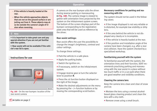
Operation
– If the vehicle is heavily loaded at therear.
– When the vehicle approaches objectsthat are not on the ground surface or arejutting out from it. These objects may al-so be outside the camera's angle of vi-sion when reversing.
Note
● It is important to take great care and payspecial attention if you are not yet familiarwith the system.
● Rear assist will not be available if the vehi-cle's rear lid is open.
Instructions for use
Fig. 180 On the rear bumper: location of therear assist camera
››› table on page 2
A camera on the rear bumper aids the driverduring reverse parking or manoeuvring››› Fig. 180. The camera image is viewed to-gether with orientation lines projected by thesystem on the Infotainment system screen.The bottom of the screen displays part of thebumper corresponding to the registrationplate area that will be used as reference bythe driver.
Rear assist settings:
Rear assist offers the user the possibility tochange the image's brightness, contrast andcolour settings.
To change these settings:
● Park the vehicle in a safe place.
● Apply the parking brake.
● Switch the ignition on.
● If necessary, switch on the Infotainmentsystem.
● Engage reverse gear or turn the selectorlever to position R.
● Press the function button displayed onthe right of the image.
● Make the desired adjustments on the menuby pressing the –/+ function buttons or bymoving the corresponding scroll button.
Necessary conditions for parking and ma-noeuvring with the
The system should not be used in the follow-ing cases:
● If the image displayed is not very reliable oris distorted, for example low visibility or dirtylens.
● If the area behind the vehicle is not dis-played very clearly or is incomplete.
● If the vehicle is heavily loaded at the rear.
● If the position and installation angle of thecamera have been changed, e.g. after a rear-end collision. Have the system checked by aspecialised workshop.
Familiarising yourself with the system
To familiarise yourself with the system, theorientation lines and their function, SEAT rec-ommends practising parking and manoeu-vring with the rear assist in a place withouttoo much traffic or in a car park when thereare good weather and visibility conditions.
Cleaning the camera lens
Keep the camera lens clean and clear of snowand ice:
● Moisten the lens using a normal alcohol-based glass cleaning product and clean thelens with a dry cloth.
● Remove snow using a small brush.
182
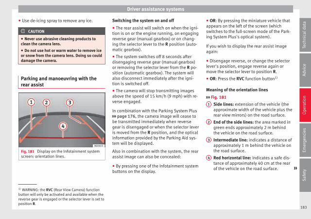
Driver assistance systems
● Use de-icing spray to remove any ice.
CAUTION
● Never use abrasive cleaning products toclean the camera lens.
● Do not use hot or warm water to remove iceor snow from the camera lens. Doing so coulddamage the camera.
Parking and manoeuvring with therear assist
Fig. 181 Display on the Infotainment systemscreen: orientation lines.
Switching the system on and off
● The rear assist will switch on when the igni-tion is on or the engine running, on engagingreverse gear (manual gearbox) or on chang-ing the selector lever to the R position (auto-matic gearbox).
● The system switches off 8 seconds afterdisengaging reverse gear (manual gearbox)or removing the selector lever from the R po-sition (automatic gearbox). The system willalso disconnect immediately after the igni-tion is switched off.
● The camera will stop transmitting imagesabove the speed of 15 km/h (9 mph) with re-verse engaged.
In combination with the Parking System Plus››› page 176, the camera image will cease tobe transmitted immediately when reversegear is disengaged or when the selector leveris moved from the R position, and the opticalinformation provided by the Parking Aid sys-tem will be displayed.
Also in combination with the system, the rearassist image can also be concealed:
● By pressing one of the Infotainment systembuttons on the display.
● OR: By pressing the miniature vehicle thatappears on the left of the screen (whichswitches to the full-screen mode of the Park-ing System Plus's optical system).
If you wish to display the rear assist imageagain:
● Disengage reverse, or change the selectorlever's position, engage reverse again ormove the selector lever to position R.
● OR: Press the RVC function button1)
Meaning of the orientation lines
››› Fig. 181
Side lines: extension of the vehicle (theapproximate width of the vehicle plus therear view mirrors) on the road surface.
End of the side lines: the area marked ingreen ends approximately 2 m behindthe vehicle on the road surface.
Intermediate line: indicates a distance ofapproximately 1 m behind the vehicle onthe road surface.
Red horizontal line: indicates a safe dis-tance of approximately 40 cm at the rearof the vehicle on the road surface. »
1
2
3
4
1) WARNING: the RVC (Rear View Camera) functionbutton will only be activated and available when thereverse gear is engaged or the selector lever is set toposition R.
183
Tech
nica
l dat
aA
dvic
eO
pera
tion
Emer
genc
ies
Saf
ety
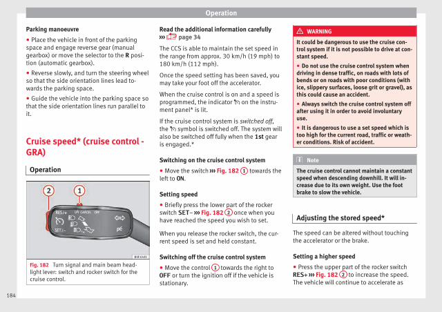
Operation
Parking manoeuvre
● Place the vehicle in front of the parkingspace and engage reverse gear (manualgearbox) or move the selector to the R posi-tion (automatic gearbox).
● Reverse slowly, and turn the steering wheelso that the side orientation lines lead to-wards the parking space.
● Guide the vehicle into the parking space sothat the side orientation lines run parallel toit.
Cruise speed* (cruise control -GRA)
Operation
Fig. 182 Turn signal and main beam head-light lever: switch and rocker switch for thecruise control.
Read the additional information carefully››› page 34
The CCS is able to maintain the set speed inthe range from approx. 30 km/h (19 mph) to180 km/h (112 mph).
Once the speed setting has been saved, youmay take your foot off the accelerator.
When the cruise control is on and a speed isprogrammed, the indicator on the instru-ment panel* is lit.
If the cruise control system is switched off,the symbol is switched off. The system willalso be switched off fully when the 1st gearis engaged.*
Switching on the cruise control system
● Move the switch ››› Fig. 182 1 towards theleft to ON.
Setting speed
● Briefly press the lower part of the rockerswitch SET– ››› Fig. 182 2 once when youhave reached the speed you wish to set.
When you release the rocker switch, the cur-rent speed is set and held constant.
Switching off the cruise control system
● Move the control 1 towards the right toOFF or turn the ignition off if the vehicle isstationary.
WARNING
It could be dangerous to use the cruise con-trol system if it is not possible to drive at con-stant speed.
● Do not use the cruise control system whendriving in dense traffic, on roads with lots ofbends or on roads with poor conditions (withice, slippery surfaces, loose grit or gravel), asthis could cause an accident.
● Always switch the cruise control system offafter using it in order to avoid involuntaryuse.
● It is dangerous to use a set speed which istoo high for the current road, traffic or weath-er conditions. Risk of accident.
Note
The cruise control cannot maintain a constantspeed when descending downhill. It will in-crease due to its own weight. Use the footbrake to slow the vehicle.
Adjusting the stored speed*
The speed can be altered without touchingthe accelerator or the brake.
Setting a higher speed
● Press the upper part of the rocker switchRES+ ››› Fig. 182 2 to increase the speed.The vehicle will continue to accelerate as
184

Driver assistance systems
long as you keep the rocker switch pressed.When you release the switch, the new speedis stored.
Setting a lower speed
● Press the lower part of the rocker switchSET– ››› Fig. 182 2 to reduce the speed. Thevehicle will automatically reduce its speed foras long as you keep the switch pressed.When you release the switch, the new speedis stored.
When you increase speed with the accelera-tor and then release the pedal, the systemwill automatically restore the set speed. Thiswill not be the case, however, if the vehiclespeed exceeds the stored speed by morethan 10 km/h (6 mph) for longer than 5 mi-nutes. The speed will have to be storedagain.
Cruise control is switched off if you reducespeed by depressing the brake pedal. Reacti-vate the control by pressing once on the up-per part of the rocker switch RES+ ››› Fig. 182
2 .
Temporary deactivation of cruise con-trol*
The cruise control system will be switched offin the following situations:
● if the brake pedal is depressed,
● if the clutch pedal is depressed,
● if the vehicle is accelerated to over180 km/h (112 mph),
● when the lever 1 is moved in the directionof OFF without being fully engaged.
To resume cruise control, release the brake orclutch pedal or reduce the vehicle speed toless than 180 km/h (112 mph) and pressonce on the upper part of the rocker switchRES+ ››› Fig. 182 2 .
Complete system deactivation
Vehicles with a manual gearbox
The system is completely turned off by mov-ing the control ››› Fig. 182 1 -- all the way tothe right hand side (set into the OFF posi-tion), or when the vehicle is stationary,switching off the ignition.
Vehicles with an automatic gearbox
To completely disengage the system, the se-lector lever must be placed in one of the fol-lowing positions: P, N, R or 1 or with the vehi-cle stopped and the ignition turned off.
“SEAT Drive Profile” system
Function and operation
Fig. 183 In the centre console: button to ad-just the "SEAT Drive Profile" system
The “SEAT Drive Profile” system modifies thesuspension system's characteristics andpower steering behaviour.
you can choose between 2 different settingswith different characteristics.
CONVEN-IENCE
Balanced setting, suitable, e.g. for day-to-day use.
SPORTThis gives the vehicle sporty characteristicsand is suitable for a sporty driving style.
Settings can be changed when the vehicle isstationary or in movement. When a “SEATDrive Profile” setting is changed it is activa-ted immediately. »
185
Tech
nica
l dat
aA
dvic
eO
pera
tion
Emer
genc
ies
Saf
ety
Operation
Selecting the system setting
● If necessary, switch on the ignition.
● To select SPORT mode, press the ››› Fig. 183 button until it lights up.
The CONVENIENCE mode is active when the button is not lit. The set mode remains
selected after the ignition is switched off.
CUPRA vehicle version
The modes of operation for the CUPRA areNormal and Sport rather than Comfort andSport. The vehicle always starts up in Nor-mal. The last selection does not remain oncethe vehicle is turned off.
WARNING
Adjusting the “SEAT Drive Profile” modifiesdriving properties. The “SEAT Drive Profile”system should never encourage you to takerisks.
● Adapt your speed and driving style at alltimes to suit visibility, weather, road and traf-fic conditions.
WARNING
If the warning lamps and the correspondingmessages are ignored when they light up, thevehicle may stall in traffic and cause acci-dents and severe injuries.
● Never ignore the warning lamps or messag-es.
● Stop the vehicle at the next opportunityand in a safe place.
CAUTION
Failure to heed the control lamps and corre-sponding text messages when they light upmay result in damage to the vehicle.
Note
If the “SEAT Drive Profile” system presents afault, the symbol appears on the instrumentpanel, with the message Fault: Dampingsetting.
Indication on the display and warninglamp
There is a fault in the “SEAT Drive Pro-file” suspension.
See a specialised workshop immediately and have the“SEAT Drive Profile” suspension checked.If the yellow warning lamp does not light up again afterthe engine is restarted and the vehicle has travelled ashort distance, you do not need to take it to a special-ised workshop.
Some warning and indication lamps will lightup briefly when the ignition is switched on tocheck certain functions. They will switch offafter a few seconds.
WARNING
If the warning lamps and the correspondingmessages are ignored when they light up, thevehicle may stall in traffic and cause acci-dents and severe injuries.
● Never ignore the warning lamps or messag-es.
WARNING
Changing the “SEAT Drive Profile” settingswhile the vehicle is in motion can distract youfrom the road and lead to accidents.
CAUTION
Failure to heed the control lamps when theylight up and the corresponding messagesmay result in damage to the vehicle.
Note
If the “SEAT Drive Profile” system does notwork as described in this chapter, have itchecked immediately by a specialised work-shop.
186
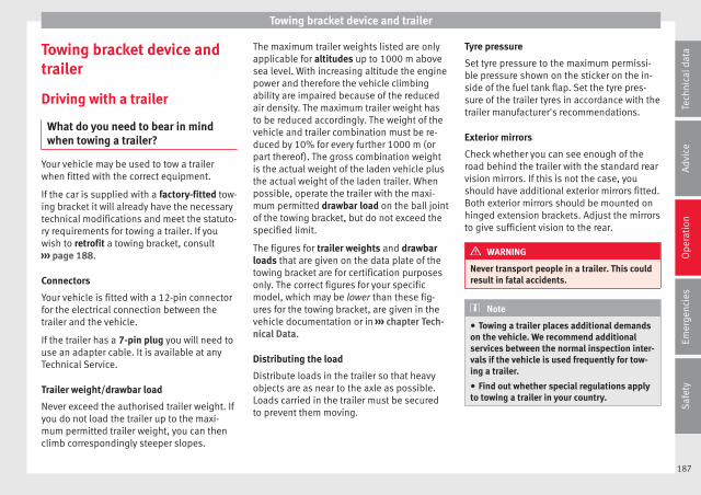
Towing bracket device and trailer
Towing bracket device andtrailer
Driving with a trailer
What do you need to bear in mindwhen towing a trailer?
Your vehicle may be used to tow a trailerwhen fitted with the correct equipment.
If the car is supplied with a factory-fitted tow-ing bracket it will already have the necessarytechnical modifications and meet the statuto-ry requirements for towing a trailer. If youwish to retrofit a towing bracket, consult››› page 188.
Connectors
Your vehicle is fitted with a 12-pin connectorfor the electrical connection between thetrailer and the vehicle.
If the trailer has a 7-pin plug you will need touse an adapter cable. It is available at anyTechnical Service.
Trailer weight/drawbar load
Never exceed the authorised trailer weight. Ifyou do not load the trailer up to the maxi-mum permitted trailer weight, you can thenclimb correspondingly steeper slopes.
The maximum trailer weights listed are onlyapplicable for altitudes up to 1000 m abovesea level. With increasing altitude the enginepower and therefore the vehicle climbingability are impaired because of the reducedair density. The maximum trailer weight hasto be reduced accordingly. The weight of thevehicle and trailer combination must be re-duced by 10% for every further 1000 m (orpart thereof). The gross combination weightis the actual weight of the laden vehicle plusthe actual weight of the laden trailer. Whenpossible, operate the trailer with the maxi-mum permitted drawbar load on the ball jointof the towing bracket, but do not exceed thespecified limit.
The figures for trailer weights and drawbarloads that are given on the data plate of thetowing bracket are for certification purposesonly. The correct figures for your specificmodel, which may be lower than these fig-ures for the towing bracket, are given in thevehicle documentation or in ››› chapter Tech-nical Data.
Distributing the load
Distribute loads in the trailer so that heavyobjects are as near to the axle as possible.Loads carried in the trailer must be securedto prevent them moving.
Tyre pressure
Set tyre pressure to the maximum permissi-ble pressure shown on the sticker on the in-side of the fuel tank flap. Set the tyre pres-sure of the trailer tyres in accordance with thetrailer manufacturer's recommendations.
Exterior mirrors
Check whether you can see enough of theroad behind the trailer with the standard rearvision mirrors. If this is not the case, youshould have additional exterior mirrors fitted.Both exterior mirrors should be mounted onhinged extension brackets. Adjust the mirrorsto give sufficient vision to the rear.
WARNING
Never transport people in a trailer. This couldresult in fatal accidents.
Note
● Towing a trailer places additional demandson the vehicle. We recommend additionalservices between the normal inspection inter-vals if the vehicle is used frequently for tow-ing a trailer.
● Find out whether special regulations applyto towing a trailer in your country.
187
Tech
nica
l dat
aA
dvic
eO
pera
tion
Emer
genc
ies
Saf
ety

Operation
Ball coupling of towing bracket*
The ball coupling is provided with instruc-tions on fitting and removing the ball cou-pling of the towing bracket.
WARNING
The towing bracket ball coupling must bestored securely in the luggage compartmentto prevent them being flung through the vehi-cle and causing injury.
Note
● By law, the ball coupling must be removedif a trailer is not being towed if it obscuresthe number plate.
Driving tips
Driving with a trailer always requires extracare.
Weight distribution
The weight distribution of a loaded trailerwith an unladen vehicle is very unfavourable.However, if this cannot be avoided, drive ex-tra slowly to allow for the unbalanced weightdistribution.
Speed
The stability of the vehicle and trailer is re-duced with increasing speed. For this reason,it is advisable not to drive at the maximumpermissible speed in an unfavourable road,weather or wind conditions. This applies es-pecially when driving downhill.
You should always reduce speed immediatelyif the trailer shows the slightest sign of snak-ing. Never try to stop the “snaking” by in-creasing speed.
Always brake in due course. If the trailer hasan overrun brake, apply the brakes gently atfirst and then, firmly. This will prevent thejerking that can be caused by locking of trail-er wheels. Select a low gear in due coursebefore going down a steep downhill. This en-ables you to use the engine braking to slowdown the vehicle.
Reheating
At very high temperatures and during pro-longed slopes, driving with a low gear andhigh engine speed; always monitor whetherthe excessive coolant temperature gauge isactivated ››› page 106.
Retrofitting a towing bracket*
Fig. 184 IBIZA/IBIZA SC: attachment pointsfor towing bracket.
If a towing bracket is to be fitted after the ve-hicle is purchased, this must be completedaccording to the instructions of the towingbracket manufacturer.
188

Towing bracket device and trailer
The attachment points A for the towingbracket are underneath the vehicle.
The distance between the centre of the ballcoupling and the ground should never belower than the indicated value, even with afully loaded vehicle and including the maxi-mum drawbar load.
Elevation values for securing the towing bracket:
IBIZA IBIZA SC IBIZA ST
B 65 mm (minimum)
C 350 mm to 420 mm (fully laden vehicle)
D 959 mm
E 438 mm 379 mm
F 209 mm 386 mm
Fitting a towing bracket
● Driving with a trailer involves an extra effortfor the vehicle. Therefore, before fitting atowing bracket, please contact a TechnicalService to check whether your cooling systemneeds modification.
● The legal requirements in your countrymust be observed (e.g. the fitting of a sepa-rate control lamp).
● Certain vehicle components, for examplethe rear bumper, must be removed and rein-stalled. The towing bracket securing boltsmust be tightened using a torque wrench,
and a power socket must be connected to thevehicle electrical system. This requires speci-alised knowledge and tools.
● Figures in the illustration show the eleva-tion value and the attachment points whichmust be considered if you are retrofitting atowing bracket.
WARNING
The towing brackets should be fitted at a spe-cialised workshop.
● If the towing bracket is incorrectly instal-led, there is a serious danger of accident.
● For your own safety, please observe the towbracket manufacturer's instructions.
CAUTION
● If the power socket is incorrectly installed,this could cause damage to the vehicle elec-trical system.
Note
● SEAT recommends that the towing hooksbe fitted at a specialised workshop. In certainversions this may entail fitting a heat insulat-ing plate, which is why it is recommendedthat you go to a SEAT Dealer. In the event thatthe plate is not installed correctly, SEAT is ex-empt from any liability.
● Due to the specific design of the exhaust,the fitting of a conventional towing hook is
not recommended for some sportier versions.Please consult your Technical Service.
189
Tech
nica
l dat
aA
dvic
eO
pera
tion
Emer
genc
ies
Saf
ety

Advice
Advice
Care and maintenance
Accessories and modificationsto the vehicle
Accessories, replacement of parts andmodifications
Your vehicle is designed to offer a highstandard of active and passive safety.
Before purchasing accessories and parts,and before making technical changes to yourvehicle, we recommend that you consult yourTechnical Service.
SEAT dealerships will be happy to provideyou with the latest information about theuse, legal requirements and recommenda-tions from the manufacturer regarding acces-sories and spare parts.
We recommend you use only SEAT ApprovedAccessories® and SEAT Approved SpareParts®. This way, SEAT can guarantee thatthe product in question is suitable, reliableand safe. SEAT Technical Services have thenecessary experience and facilities to ensurethat parts are correctly and professionally in-stalled.
Despite a continuous observation of the mar-ket, SEAT is not able to assess the reliability,safety and suitability of parts that SEAT hasnot approved. For this reason, SEAT cannotassume responsibility for any non-genuineparts used, even if these parts have been ap-proved by an official testing agency or arecovered by an official approval certificate.
Any retro-fitted equipment which has a directimpact on the driver's control of the vehicle,such as a cruise control system or electroni-cally-controlled suspension, must be ap-proved by SEAT for use in your vehicle andbear the e mark (the European Union's au-thorisation symbol).
If any additional electrical devices are fittedwhich do not serve to control the vehicle it-self, such as refrigerator boxes, laptops orventilator fans, they must bear the CE mark(European Union manufacturer conformitydeclaration).
WARNING
Accessories, for example telephone holdersor cup holders, should never be fitted on thecovers, or within the working range, of theairbags. Otherwise, there is a danger of in-jury if the airbag is triggered in an accident.
Modifications
Modifications must always be carried out ac-cording to our specifications. Unauthorisedmodifications to the electronic componentsor software in the vehicle may cause malfunc-tions. Due to the way the electronic compo-nents are linked together in networks, otherindirect systems may be affected by thefaults. This can seriously impair safety, leadto excessive wear of components, and alsoinvalidate your vehicle registration docu-ments.
SEAT Technical Services cannot be held liablefor any damage caused by modificationsand/or work incorrectly performed. For thisreason, we recommend having all work per-formed by a SEAT Technical Service usingSEAT® Original Spare Parts.
WARNING
Any type of work or modification performedincorrectly on your vehicle can lead to mal-functions and can cause accidents.
Roof aerial*
The vehicle can be fitted with a foldable* andanti-theft* roof aerial which can be foldedbackwards, for example when going throughan automatic car wash.
190

Care and maintenance
To fold
Unscrew the aerial rod, tilting it backwardsinto a horizontal position and then screw inagain.
To return to working position
Continue in the reverse order to the previousinstruction.
CAUTION
If an automatic car wash tunnel is used, be-fore entering the tunnel, put the aerial downparallel to the roof and do not tighten toavoid damage.
Mobile phones and two-way radios
SEAT has approved for your vehicle the use ofmobile telephones and two-way radios pro-viding under the following conditions:
● The external aerial should be correctly in-stalled.
● The transmitting power should be a maxi-mum 10 watts.
The optimal reach of the equipment is onlyachieved with an external aerial.
First consult your Technical Service if youwish to use a mobile telephone or a two-wayradio with a transmitting power output in ex-cess of 10 watts. Here you will receive infor-
mation concerning the technical possibilitiesfor retrofitting this equipment.
Mobile telephones and two-way radiosshould be only fitted by a specialised work-shop, for example a SEAT dealership.
WARNING
● Always concentrate primarily on driving. Ifyou are distracted while driving you couldhave an accident.
● Never attach the telephone mountings tothe surfaces covering the airbag units orwithin the range of the airbags. There is ahigh danger of injury if the airbag is trig-gered.
● Using your mobile telephones or two-wayradios in the vehicle without an external aer-ial, electromagnetic radiation in the vehiclecould exceed authorised limits. This also mayoccur to external aerials that have not beencorrectly installed.
CAUTION
Failure to consider the above-mentioned con-ditions could cause the electronics to mal-function. The most common causes of faultsare:
● no external aerial,
● external aerial incorrectly installed,
● transmitting power output in excess of 10watts.
Note
Please observe the operating instructions ofyour mobile telephone/two-way radio.
Care and cleaning
General notes
Vehicle maintenance
Regular care and washing help to maintainthe value of the vehicle. This may also be oneof the requirements for acknowledging war-ranty claims in the event of bodywork corro-sion or paint defects.
The best way to protect your vehicle againstthe harmful effects of the environment isthrough correct maintenance and frequentwashing. The longer substances such as in-sect remains, bird droppings, resinous treesap, road dirt, industrial deposits, tar, soot orroad salt and other aggressive materials re-main on the vehicle, the more damage theydo to the paintwork. High temperatures, forinstance in strong sunlight, further intensifythe corrosive effect.
After winter, a period when salt is put on theroads, it is important to have the undersideof the vehicle washed thoroughly. »
191
Tech
nica
l dat
aA
dvic
eO
pera
tion
Emer
genc
ies
Saf
ety

Advice
Products for vehicle maintenance
Car-care products are available in your Tech-nical Services. Keep the product instructionsuntil you have used them up.
WARNING
● Car-care products can be toxic. Because ofthis, they must always be kept closed in theiroriginal container. Keep them out of the reachof children. Failure to comply could result inpoisoning.
● Always read and observe the instructionsand warnings on the package before usingcar-care products. Improper use could causehealth problems or damage the vehicle. Theuse of certain products may produce noxiousvapours; they should be used in well ventila-ted areas.
● Never use fuel, turpentine, engine oil, nailvarnish remover or other volatile fluids.These are toxic and highly flammable. Risk offire and explosion.
● Before washing your vehicle, or carryingout any maintenance, switch the engine off,apply the handbrake firmly and remove thekey from the ignition.
CAUTION
Never attempt to remove dirt, mud or dust ifthe surface of the vehicle is dry. Never use adry cloth or sponge for cleaning purposes.This could damage the paintwork or the win-dows of your vehicle. Soak dirt, mud or dustwith plenty of water.
For the sake of the environment
● When purchasing car care products, try toselect ones that are not harmful to the envi-ronment.
● The waste from car-care products shouldnot be disposed of with ordinary householdwaste. Observe the disposal information onthe package.
Care of the vehicle exterior
Automatic car wash tunnel
The vehicle paintwork is so durable that thevehicle can normally be washed withoutproblems in an automatic car wash tunnel.However, the paintwork wear depends to alarge extent on the kind of the car wash tun-nel, the brushes used, its water filtering andthe type of cleaning and preservative prod-ucts.
Before going through a car wash, be sure totake the usual precautions such as closingthe windows and sunroof. There is nothing tonote apart from that.
If the vehicle has special accessories such asspoilers or a roof rack or two-way radio aerial,etc., it is advisable to consult the car washtunnel operator first.
After washing, the brakes could take sometime to respond as the brake discs and padscould be wet, or even frozen in winter. “Dry”the brakes by braking several times.
WARNING
Water, ice and salt on the brake system canreduce braking effectiveness. Risk of acci-dent.
CAUTION
Before putting the vehicle through the carwash, do not tighten the aerial if it is foldedbecause it can be damaged.
Hand-washing
Vehicle washing
– First soften the dirt and rinse it off with wa-ter.
– Clean your vehicle from top to bottom witha soft sponge, a glove or a brush. Use verylight pressure.
– Rinse the sponge or glove often with cleanwater.
– Special car shampoo should only be usedfor very stubborn dirt.
– Leave the wheels, sill panels etc. until last,using a different sponge or glove.
192

Care and maintenance
– Rinse the vehicle thoroughly with water.
– Dry the vehicle surface gently with a cha-mois leather.
– In cold temperature, dry the rubber sealsand their surfaces to prevent them fromfreezing. Apply silicone spray to the rubberseals.
After washing the vehicle
– After washing, avoid sudden and sharpbraking. “Dry” the brakes by braking sever-al times.
WARNING
● Wash your vehicle with the ignition switch-ed off.
● Protect your hands and arms from cuts onsharp metal edges when cleaning the under-body, the inside of the wheel housings etc.Risk of injury.
● Water, ice and salt on the brake system canreduce braking effectiveness. Risk of acci-dent.
CAUTION
● Never remove dirt, mud or dust if the vehi-cle surface is dry. Never use a dry cloth orsponge for cleaning purposes. This couldscratch the paintwork or glass on your vehi-cle.
● Washing the vehicle in low temperatures:when washing the vehicle with a hose, do notdirect water into the lock cylinders or thegaps around the doors, rear lid, or sunroof.Risk of freezing.
For the sake of the environment
To protect the environment, the vehicleshould be washed only in specially providedwash bays, to prevent toxic, oil-laden wastewater from entering the sewer system. Insome places, washing vehicles outside washbays is prohibited.
Note
Do not wash the vehicle in direct sunlight.
Washing the vehicle with a high pres-sure cleaner
Be particularly careful when using a highpressure cleaner!
– Always observe the instructions for thehigh-pressure cleaner, particularly thoseconcerning the pressure and the sprayingdistance.
– Increase the spraying distance for soft ma-terials and painted bumpers.
– Do not use a high pressure cleaner to re-move ice or snow from windows››› page 194.
– Never use concentrated jet nozzles (“rotat-ing jets”) ››› .
– After washing, avoid sudden and sharpbraking. “Dry” the brakes by braking sever-al times ››› page 156.
WARNING
● Never wash tyres with a concentrated jet(“rotating nozzle”). Even at large sprayingdistances and short cleaning times, damagecan occur to the tyres. This may cause an ac-cident.
● Water, ice and salt on the brake system canreduce braking effectiveness. Risk of acci-dent.
CAUTION
● Do not use water hotter than +60°C(+140°F). This could damage the vehicle.
● To avoid damage to the vehicle, keep a suf-ficient distance from sensitive materials suchas flexible hoses, plastic, soundproofing ma-terial, etc. This also applies to bumpers pain-ted in the colour of the bodywork. The closerthe nozzle is to the surface, the greater thewear on the material.
193
Tech
nica
l dat
aA
dvic
eO
pera
tion
Emer
genc
ies
Saf
ety
Advice
Sensors and camera lenses
● Use a small brush to remove snow and ade-icer spray to remove ice.
● Clean the sensors with a solvent-free prod-uct and a soft, dry cloth.
● Moisten the camera lens using a standardalcohol-based glass cleaning agent andclean the lens with a dry cloth.
CAUTION
● When you clean the vehicle with a pressurewasher:
– Stay a suitable distance from the sensorson the front and rear bumpers.
– Do not clean the camera lenses or sur-rounding area with the pressure washer.
● Never use warm or hot water to removesnow and ice from the reverse camera lens,as it could crack the lens.
● Never use abrasive cleaning agents on thelens.
Vehicle paint maintenance
Regular waxing protects the paintwork.
You need to apply wax to your vehicle if waterdoes not form small drops and run off thepaintwork when it is clean.
Good quality hard wax products are availableat your Technical Service.
Regular wax applications help to protect thepaintwork from environmental contaminants››› page 191. It is also effective in protectingagainst minor scratches.
Even if a wax solution is used regularly in thevehicle washing tunnel, it is advisable to pro-tect the paint with a hard wax coating at leasttwice a year.
Polishing the paintwork
Polishing is only necessary if the paint haslost its shine, and the gloss cannot bebrought back by applying wax. Polishingproducts can be purchased in your TechnicalService.
The vehicle must be waxed after polishing ifthe polish used does not contain wax com-pounds to seal the paint ››› page 194, Vehiclepaint maintenance.
CAUTION
To prevent damage to the paintwork:
● Do not use polishes and hard wax on pain-ted parts with a matt finish or on plasticparts.
● Do not polish your vehicle in a sandy ordusty environment.
Caring for plastic parts
If normal washing fails to clean plastic parts,clean them with approved solvent-free plas-tic cleaning and care products.
CAUTION
● The use of liquid air freshener directly overthe air vents of the vehicle may damage theplastic parts if the liquid is accidentally spil-led.
● Cleaning products which contain solventswill damage the material.
Cleaning of windows and mirrors
Cleaning windows
– Moisten the windows with commerciallyavailable, alcohol based glass cleaner.
– Dry the windows with a clean chamoisleather or a lint-free cloth.
Removing snow
– Use a small brush to remove snow from thewindows and mirrors.
Removing ice
– Use a de-icer spray.
Use a clean cloth or chamois leather to drythe windows. The chamois leathers used on
194

Care and maintenance
painted surfaces are not suitable to cleanwindows because they are soiled with waxdeposits which could smear the windows.
If possible, use a de-icing spray to removeice. If you use an ice scraper, push it in onedirection only without swinging it.
Use window cleaner or a silicone remover toclean rubber, oil, grease and silicone depos-its off.
Wax deposits can only be removed with aspecial cleaner available at your TechnicalService. Wax deposits on the windscreencould cause the wiper blades to judder. Add-ing a window cleaner that dissolves wax tothe windscreen washer fluid prevents wiperblades from juddering, but wax deposits arenot removed.
CAUTION
● Never use warm or hot water to removesnow and ice from windows and mirrors. Thiscould cause the glass to crack!
● The heating element for the rear window islocated on the inner side of the window. Toprevent damage, do not put stickers over theheating elements on the inside of the win-dow.
Cleaning windscreen wiper blades
Clean wiper blades improve visibility.
1. Use a soft cloth to remove dust and dirtfrom the windscreen wiper blades.
2. Use window cleaner to clean the wind-screen wiper blades. Use a sponge or acloth to remove stubborn dirt.
Care of rubber seals
If rubber seals are well looked after, they willnot freeze so quickly.
1. Use a soft cloth to remove dust and dirtfrom the rubber seals.
2. Apply a specialist care product to the rub-ber seals.
The rubber strips on the doors, windows, etc.will remain pliable and last longer if they aretreated with a suitable rubber care productfrom time to time (for example siliconespray).
Caring for rubber seals will also prevent pre-mature ageing and leaks. The doors will beeasier to open. If rubber seals are well lookedafter, they will not freeze so quickly in winter.
Door lock cylinder
The door lock cylinders can freeze up in win-ter.
To de-ice the lock cylinders you should onlyuse spray with lubricating and anti-corrosiveproperties.
Cleaning chrome parts
1. Clean chrome parts with a damp cloth.
2. Polish chrome parts with a soft, dry cloth.
If this does not provide satisfying results, usea specialist chrome cleaning product.Chrome cleaning products will remove stainsfrom the surface.
CAUTION
To prevent scratching chrome surfaces:
● Never use an abrasive cleaning product onchrome.
● Do not clean or polish chrome parts in asandy or dusty environment.
Steel wheel rims
– Clean steel wheel rims regularly using aseparate sponge.
Use an industrial cleaner to remove brakedust. Any damage to the paint on steel wheelrims should be repaired before starting torust. »
195
Tech
nica
l dat
aA
dvic
eO
pera
tion
Emer
genc
ies
Saf
ety

Advice
WARNING
● Never wash tyres with a cylindrical jet. Evenat large spraying distances and short clean-ing times, damage can occur to the tyres.This may cause an accident.
● Water, ice and salt on the brake system canreduce braking effectiveness. Risk of acci-dent. Directly after washing, avoid suddenand sharp braking. “Dry” the brakes by brak-ing several times ››› page 156, Braking ca-pacity and braking distance.
Alloy wheel rims
Every two weeks
– Wash salt and brake dust from alloywheels.
– Use an acid free detergent to clean thewheel rims.
Every 3 months
– Apply a hard wax compound to the wheels.
Alloy wheels require regular attention to pre-serve their appearance. If road salt and brakedust are not often removed, the aluminiumfinish will be impaired.
Always use an acid-free detergent for alloywheel rims.
Car polish or other abrasive agents shouldnot be used for maintaining the rims. If the
protective coating is damaged, e.g. by flyingstones, the damaged area should be re-paired immediately.
WARNING
Observe the safety warnings ››› in Steelwheel rims on page 196.
Vehicle underbody protection
The vehicle underbody is coated to protect itfrom chemical and mechanical damage.
The protective coating can be damaged whendriving. We recommend that you check theprotective coating under the body and on therunning gear, and retouch it if necessary, be-fore and after the winter season.
We recommend that you go to your TechnicalService to carry out repair work and addition-al anti-corrosion work.
WARNING
Do not apply underseal or anti-corrosioncoatings to the exhaust pipes, catalytic con-verter or the heat shields on the exhaust sys-tem. The heat of the exhaust system or theengine could cause them to ignite. Risk offire.
Cleaning engine compartment
Take special care when cleaning the enginecompartment.
Anti-corrosion treatment
The engine compartment and the surface ofthe power unit are given anti-corrosion treat-ment at the factory.
Good corrosion protection is particularly im-portant in winter when the vehicle is fre-quently driven on salted roads. To preventthe salt corroding the vehicle, the entire en-gine compartment should be thoroughlycleaned before and after winter.
Technical Services have the proper productsfor cleaning and preservation as well as thenecessary workshop equipment. For this rea-son, we recommend having this work per-formed by them.
The anti-corrosion protection is usually re-moved if the engine compartment is cleanedwith grease removing solutions, or if youhave the engine cleaned. On commissioningthis work, ensure that all surfaces, seams,joints and components in the engine com-partment are given anti-corrosion treatment.
WARNING
● When working in the engine compartment,always observe the safety warnings››› page 201.
196

Care and maintenance
● Before opening the bonnet, switch the en-gine off, apply the handbrake firmly and al-ways remove the key from the ignition.
● Allow the engine to cool before you cleanthe engine compartment.
● Do not clean, for example, the vehicle un-derbody, wheel arches or wheel trims withoutprotecting your hands and arms. You may cutyourself on sharp-edged metal parts. Failureto comply could result in injury.
● Moisture, ice and salt on the brake systemmay affect braking effectiveness. Risk of acci-dent. Directly after washing, avoid suddenand sharp braking.
● Never touch the radiator fan. It is tempera-ture-controlled and could start automatically,even when the key is removed from the igni-tion!
For the sake of the environment
Fuel, grease and oil deposits can be removedwhen the engine is washed. The polluted wa-ter must be cleaned in an oil separator. Forthis reason, engine washing should be car-ried out only by a specialised workshop or apetrol station.
Caring for the vehicle interior
Cleaning plastic parts and the dashpanel
– Use a clean, damp cloth to clean plasticparts and the dash panel.
– If this does not provide satisfactory results,use a special solvent-free plastic cleaningproduct.
WARNING
Never clean the dash panel and the airbagmodule surface with cleaners containing sol-vents. Solvents cause the surface to becomeporous. If the airbag triggered, plastic partscould become detached and cause injuries.
CAUTION
Cleaning products which contain solvents willdamage the material.
Cleaning wooden trim*
– Clean the wooden trim with a water-mois-tened clean cloth.
– If this does not provide satisfactory results,use a gentle soap solution.
CAUTION
Cleaning products which contain solvents willdamage the material.
Cleaning upholstery and fabric trim
Cloth seat covers and fabric trim on thedoors, headlining etc. can be cleaned with aspecial interior cleaner or with dry foam anda soft brush.
Cleaning the radio and climate con-trols
To clean the radio and/or climate controls,use a soft damp cloth. For more resistant dirt,a neutral soap solution may be used.
Cleaning leather*
Normal cleaning
– Moisten a cotton or woollen cloth with wa-ter and wipe over the leather surfaces.
Cleaning stubborn stains
– More stubborn dirt can be removed using amild soap solution (pure liquid soap; twotablespoons diluted in one litre of water)and a cloth. »
197
Tech
nica
l dat
aA
dvic
eO
pera
tion
Emer
genc
ies
Saf
ety
Advice
– Do not let the water soak through the leath-er or soak into the seams.
– Then wipe off with a soft, dry cloth.
Leather maintenance
– The leather should be treated twice a yearwith a special leather-care product, availa-ble at Technical Services.
– Apply these products very sparingly.
– Then wipe off with a soft, dry cloth.
SEAT does everything possible to preservethe genuine qualities of this natural product.Due to the natural properties of the speciallyselected hides employed, the finished leath-er has a certain sensitivity to grease and dirt,etc. so a degree of care is required in every-day use and when looking after the leather.
Dust and grit in the pores and seams canscratch and damage the surface. If the vehi-cle is under solar radiation for long periods,the leather should be protected to prevent itfrom fading. However, slight colour variationsin high-quality natural leather are normal.
CAUTION
● Do not use solvents, wax polish, shoecream, spot removers or similar products onleather.
● To avoid damage, stubborn stains shouldbe removed by a specialised workshop.
Seat belt cleaning
A dirty belt may not work properly. Check allseat belts regularly and keep them clean.
Seat belts cleaning
– Pull the dirty seat belt right out and unrollit.
– Clean dirty seat belts with a gentle soapsolution.
– Allow it to dry.
– Do not roll the seat belt up until it is dry.
If large stains form on the belts, the automat-ic belt retractor will not work correctly.
WARNING
● Do not use chemical cleaning agents on theseat belts, as this can impair the strength ofthe webbing. Ensure that seat belts do notcome into contact with corrosive fluids.
● Check the condition of the seat belts at reg-ular intervals. If you notice that the belt web-bing, fittings, retractor mechanism or buckleof any of the belts is damaged, the belt mustbe replaced by a specialised workshop.
● Do not attempt to repair a damaged seatbelt yourself. The seat belts must not be re-moved or modified in any way.
CAUTION
After cleaning, allow seat belts to dry com-pletely before rolling them up. Otherwise, thebelt retractors could become damaged.
198

Checking and refilling levels
Checking and refilling levels
Fuel
Refuelling
Read the additional information carefully››› page 41
The tank flap is released manually and is lo-cated at the rear of the vehicle on the right.The tank holds approximately 45 litres.
Opening the fuel tank cap
– Lift the lid.
– Hold the cap firmly with one hand, then in-sert the key into the lock and rotate 180° tothe left.
– Unscrew the cap, turning it anticlockwise.
Closing the fuel tank cap
– Screw the tank cap to the right until it“clicks”.
– Turn the key in the lock, without releasingthe cap, clockwise through 180°.
– Remove the key and close the flap until itclicks into place. The tank cap is securedwith an anti-loss attachment
If the automatic filler nozzle is operated cor-rectly, it will switch itself off as soon as the
tank is “full”. Never attempt to fill beyondthis point, as this will fill the expansionchamber. Fuel may leak out if ambient condi-tions are warm.
The correct fuel grade for your vehicle is giv-en on a sticker on the inside of the fuel tankflap.
WARNING
● Fuel is highly flammable and can cause se-rious burns and other injuries.
– Never smoke or come into contact withsparks when filling the fuel tank of thevehicle or a spare fuel canister with fuel.This is an explosion hazard.
– Follow legal requirements for the use ofspare fuel canisters.
– For safety reasons we do not recommendcarrying a spare fuel canister in the vehi-cle. The canister could be damaged in anaccident and leak.
● If, in exceptional circumstances, you haveto carry a spare fuel canister, please observethe following:
– Never fill the spare fuel canister insidethe vehicle or on it. An electrostaticcharge could build up during filling, caus-ing the fuel fumes to ignite. This couldcause an explosion. Always place thecanister on the ground to fill it.
– Insert the fuel nozzle into the mouth ofthe canister as far as possible.
– If the spare fuel canister is made of met-al, the filling nozzle must be in contactwith the canister during filling. Thishelps prevent an electrostatic chargebuilding up.
– Never spill fuel in the vehicle or in theluggage compartment. Fuel vapours areexplosive. Danger of death.
CAUTION
● Fuel spills should be removed from thepaintwork immediately.
● Never run the tank completely dry. Irregularfuel supply can cause misfiring. As a result,unburnt fuel could enter the catalytic convert-er and cause damage.
● When filling the fuel tank after having run itcompletely dry on a vehicle with a diesel en-gine the ignition must be switched on for atleast 30 seconds before starting the engine.Subsequently, when you start the engine itmay take longer than normal to start firing(up to one minute). This is due to the fact thatthe fuel system has to purge itself of air be-fore starting.
For the sake of the environment
Do not try to put in more fuel after the auto-matic filler nozzle has switched off, this maycause the fuel to overflow if it becomes warm.
199
Tech
nica
l dat
aA
dvic
eO
pera
tion
Emer
genc
ies
Saf
ety

Advice
Petrol
Petrol types
The correct petrol types are listed on a stickerinside the fuel tank flap.
Only unleaded petrol conforming to standardDIN EN 228 may be used for vehicles withcatalytic converters (EN = “European Stand-ard”).
Types of petrol differ from each other accord-ing to the octane rating, for example: 91, 95,98 RON (RON = “Research Octane Number”,unit for determining the knock resistance ofpetrol). You may use petrol with a higher oc-tane number than the one recommended foryour engine. However, this has no advantagein terms of fuel consumption and enginepower.
CAUTION
● Even one tankful of leaded fuel would per-manently impair the efficiency of the catalyt-ic converter.
● High engine speed and full throttle candamage the engine when using petrol with anoctane rating lower than the correct grade forthe engine.
For the sake of the environment
Just one full tank of leaded fuel would seri-ously impair the efficiency of the catalyticconverter.
Additives for petrol
The quality of the fuel influences the behav-iour, power and service life of the engine.
This is why the petrol you use should carrysuitable additives already included by thepetrol industry, free of metals. These addi-tives will help to prevent corrosion, keep thefuel system clean and prevent deposits frombuilding up in the engine.
If good-quality petrol with metal-free addi-tives is not available or engine problemsarise, the necessary additives must be addedwhen refuelling.
Not all petrol additives have been shown tobe effective. The use of unsuitable petrol ad-ditives may cause significant damage to theengine and the catalytic converter. Metal ad-ditives should never be used. Metal additivesmay also be contained in petrol additives forimproving anti-detonation ratings or octaneratings.
SEAT recommends “genuine VolkswagenGroup fuel additives for petrol engines”.These additives can be bought at SEAT deal-ers, where information on how to use themcan also be obtained.
CAUTION
Do not refuel if the filler indicates that thefuel contains metal. LRP (lead replacementpetrol) fuels contain high concentrations ofmetal additives. Using them may damage theengine!
Diesel
Diesel
Diesel fuel must conform to DIN EN 590 (EN =“European Standard”). It must have a cetanenumber (CN) of at least 51. The cetane num-ber indicates the ignition quality of the dieselfuel.
Notes on refuelling ››› page 199.
Water in the fuel filter1)
If your vehicle has a diesel engine and isequipped with a fuel filter with a water sepa-rator, the instrument panel may display thefollowing warning:
1) Depending on the market.200

Checking and refilling levels
Water in the fuel filter.If this is the case, take the vehicle to a speci-alised workshop so that they can drain thefuel filter.
Biodiesel*
CAUTION
● Your vehicle is not designed to use biodie-sel fuel. Never, under any circumstances re-fuel with biodiesel. The use of biodiesel fuelcould damage the engine and the fuel sys-tem. The addition of biodiesel to diesel fuelby the diesel manufacturer in accordancewith standard EN 590 or DIN 51628 is author-ised and will not cause damage to the engineor the fuel system.
● The diesel engine has been designed to beused exclusively with diesel fuel conformingto standard EN 590. Never refuel or use pet-rol, kerosene, fuel oil or any other type offuel. If you accidentally fill up the vehiclewith the wrong type of fuel, do not start theengine. Seek assistance from specialised per-sonnel. The composition of these fuels mayseverely damage the fuel system and the en-gine.
Winter operation
Winter-grade diesel
When using “summer-grade diesel fuel”, dif-ficulties may be experienced at temperaturesbelow 0°C (+32°F) because the fuel thickensdue to wax separation. For this reason, “win-ter-grade diesel fuel” is available in somecountries during the cold months. It can beused at temperatures as low as -22°C (-8°F).
In countries with different climatic conditionsthe diesel fuel generally sold has differenttemperature characteristics. Check with theTechnical Services or filling stations in thecountry concerned regarding the type of die-sel fuels available.
Filter pre-heater
Your vehicle is fitted with a fuel filter glowplug system, making it well equipped for op-eration in winter. This ensures that the fuelsystem remains operational to approx. -24°C(-11°F), provided you use winter-grade dieselwhich is safe to -15°C (+5°F).
However, if the fuel has waxed to such an ex-tent that the engine will not start at tempera-tures of under -24°C (-11°F), simply place thevehicle in a warm place for a while.
CAUTION
Do not mix fuel additives, the so-called “thin-ners”, or similar additives with diesel fuel.
Working in the engine compart-ment
safety notes for work in the enginecompartment
Read the additional information carefully››› page 10
Before starting any work on the engine or inthe engine compartment:
1. Switch off the engine and remove the keyfrom the ignition.
2. Apply the handbrake.
3. Move the gear lever to neutral or the selec-tor lever to position P.
4. Wait for the engine to cool down.
5. Keep children away from the vehicle.
6. Raise the bonnet ››› page 203.
You should not do any work in the enginecompartment unless you know exactly how tocarry out the jobs and have the correct tools!Have the work carried out by a specialisedworkshop if you are uncertain.
All service fluids and consumables, e.g. cool-ant, engine oil, spark plugs and batteries,are under constant development. SEAT pro-vides a constant flow of information to Tech-nical Services concerning modifications. Forthis reason, we recommend you have service »
201
Tech
nica
l dat
aA
dvic
eO
pera
tion
Emer
genc
ies
Saf
ety

Advice
fluids and consumables replaced by a Techni-cal Service. Please observe the relevant in-structions ››› page 190. The engine compart-ment of the vehicle is a hazardous area ››› .
WARNING
All work on the engine or in the engine com-partment, e.g. checking and refilling fluids,involves the danger of injury and burns, acci-dents and even fire.
● Never open the bonnet if you see steam,smoke or coolant escaping from the enginecompartment. Otherwise, there is a risk ofsustaining burns. Wait until no more steam orcoolant is emitted, then allow the engine tocool before carefully opening the bonnet.
● Switch off the engine and remove the keyfrom the ignition.
● Apply the handbrake and move the gearlever to neutral or selector lever to position P.
● Keep children away from the vehicle.
● Never touch hot engine parts. There is arisk of burns.
● Never spill liquids on a hot engine or on ahot exhaust gas system. This is a fire hazard.
● Avoid causing short-circuits in the electri-cal system, particularly at the points wherethe jump leads are attached ››› page 52.The battery could explode.
● Never touch the radiator fan. It is tempera-ture controlled and could start automatically,even when the engine has been switched offand the key removed from the ignition!
● Never cover the engine with additional in-sulating materials such as a blanket. Risk offire!
● Do not unscrew the cap on the coolant ex-pansion tank when the engine is hot. If thecoolant is hot, the cooling system will bepressurised!
● Protect face, hands and arms by coveringthe cap with a large, thick cloth to protectagainst escaping coolant and steam.
● Always make sure you have not left any ob-jects, such as cleaning cloths or tools, in theengine compartment.
● If you have to work underneath the vehicle,you must use suitable stands additionally tosupport the vehicle, there is a risk of acci-dent!. A hydraulic jack is insufficient for se-curing the vehicle and there is a risk of injury.
● If any work has to be performed when theengine is started or with the engine running,there is an additional, potentially fatal, safetyrisk from the rotating parts, such as the drivebelts, alternator, radiator fan, etc., and fromthe high-voltage ignition system. You shouldalso observe the following:
– Never touch the electrical wiring of theignition system.
– Ensure that jewellery, loose clothing andlong hair do not get trapped in rotatingengine parts. Danger of death. Beforestarting any work remove jewellery, tieback and cover hair, and wear tight-fit-ting clothes.
– Never accelerate with a gear engagedwithout taking the necessary precau-tions. The vehicle could move, even if thehandbrake is applied. Danger of death.
● If work has to be carried out on the fuelsystem or on electrical components, youmust observe the following safety notes inaddition to the above warnings:
– Always disconnect the battery from theon-board network. The vehicle must beunlocked when this is done, otherwisethe alarm will be triggered.
– Do not smoke.
– Never work near naked flames.
– Always have a fire extinguisher on hand.
WARNING
If the bonnet is not correctly closed, it couldsuddenly open while driving leaving the driv-er without visibility. This could result in a se-rious accident.
● After closing the bonnet, always check thatit is properly secured by the locking mecha-nism in the lock carrier piece. The bonnetmust be flush with the surrounding body pan-els.
● While driving, if you notice that the bonnetis not correctly closed then stop immediatelyand close it correctly.
● Only open and close the bonnet when thereis nobody within its range.
202

Checking and refilling levels
CAUTION
When topping up service fluids, make surenot to mistake them. Using the wrong fluidscould cause serious malfunctions and enginedamage!
For the sake of the environment
Service fluids leaks are harmful to the envi-ronment. For this reason you should makeregular checks on the ground underneathyour vehicle. If you find spots of oil or otherfluids, have your vehicle inspected in a speci-alised workshop.
Opening the bonnet
Read the additional information carefully››› page 10
The bonnet is released from inside the vehi-cle.
Before opening the bonnet ensure that thewindscreen wipers are in rest position.
WARNING
Hot coolant can scald!
● Never open the bonnet if you see steam,smoke or coolant escaping from the enginecompartment.
● Wait until no more steam, smoke or coolantis emitted from the bonnet, then carefullyopen the bonnet.
● When working in the engine compartment,always observe the safety warnings››› page 201.
Closing the bonnet
– Slightly lift the bonnet.
– Release the bonnet stay and replace it in itssupport.
– At a height of approximately 30 cm let it fallso it locks.
If the bonnet does not close, do not pressdownwards. Open it again and let it fall asmentioned above.
WARNING
If the bonnet is not closed properly, it couldopen while you are driving and completelyobscure your view of the road. Risk of acci-dent.
● After closing the bonnet, always check thatit is properly secured. The bonnet must beflush with the surrounding body panels.
● If you notice that the bonnet latch is not se-cured when the vehicle is moving, stop thevehicle immediately and close the bonnetproperly. Risk of accident.
203
Tech
nica
l dat
aA
dvic
eO
pera
tion
Emer
genc
ies
Saf
ety

Advice
Checking levels
Fig. 185 Diagram for the location of the various elements.
Fig. 186 For vehicles with the battery in theluggage compartment.
From time to time, the levels of the differentfluids in the vehicle must be checked. Neverfill with incorrect fluids, otherwise seriousdamage to the engine may be caused.
Coolant expansion tank
Engine oil level dipstick
Engine oil filler cap
Brake fluid reservoir
Vehicle battery
Windscreen washer reservoir
The checking and refilling of service fluidsare carried out on the components men-tioned above. These operations are descri-bed in ››› page 201.
Overview
You will find further explanations, instruc-tions and restrictions on the technical speci-fications as of ››› page 217.
1
2
3
4
5
6
Note
The layout of parts may vary depending onthe engine.
Engine oil
General notes
The engine comes with a special, multi-gradeoil that can be used all year round.
Because the use of high-quality oil is essen-tial for the correct operation of the engineand its long useful life, when topping up orchanging oil, use only those oils that complywith VW standards.
204

Checking and refilling levels
The specifications (VW standards) set out inthe following page should appear on the con-tainer of the service oil; when the containerdisplays the specific standards for petrol anddiesel engines together, it means that the oilcan be used for both types of engines.
We recommend that the oil change indicatedin the Maintenance Programme, be per-formed by a technical service or specialisedworkshop.
The correct oil specifications for your engineare listed in the ››› page 41.
Service intervals
Service intervals can be flexible (LongLifeservice) or fixed (dependent on time/dis-tance travelled).
If the PR code that appears on the back of theMaintenance Programme booklet is PR QI6,this means that your vehicle has the LongLifeservice program. If it lists the codes QI1, QI2,QI3, QI4 or QI7, the interval service is de-pendent on the time/distance travelled.
Flexible service intervals (LongLife serviceintervals*)
Special oils and processes have been devel-oped which, depending on the characteris-tics and individual driving profiles, enablethe extension of the oil change service (Long-Life service intervals).
Because this oil is essential for extending theservice intervals, it must only be used ob-serving the following indications:
● Avoid mixing it with oil for fixed service in-tervals.
● Only in exceptional circumstances, if theengine oil level is too low ››› page 206 andLongLife oil is not available, it is permitted totop up (once) with oil for fixed service inter-vals ››› page 41 (up to a maximum of 0.5litres).
Fixed service intervals*
If your vehicle does not have the “LongLifeservice interval” or it has been disabled (byrequest), you may use oils for fixed serviceintervals, which also appear in››› page 41. In this case, your vehiclemust be serviced after a fixed interval of 1year/15,000 km (10,000 miles)(whatevercomes first) ››› Booklet Maintenance Pro-gramme.
● In exceptional circumstances, if the engineoil level is too low ››› page 206 and you can-not obtain the oil specified for your vehicle,you can add a small quantity of oil conform-ing to the specification ACEA A2 or ACEA A3(petrol engines) or ACEA B3 or ACEA B4 (die-sel engines) (up to 0.5 l).
Vehicles with diesel particulate filter*
The Maintenance Programme states whetheryour vehicle is fitted with a diesel particulatefilter.
Only VW 507 00 engine oil, with reduced ashformation, may be used in diesel enginesequipped with particulate filter. Using othertypes of oil will cause a higher soot concen-tration and reduce the life of the DPF. There-fore:
● Avoid mixing this oil with other engine oils.
● Only in exceptional circumstances, if theengine oil level is too low ››› page 206 andyou cannot obtain the oil specified for yourvehicle, you can use a small quantity of oil(once) conforming to the VW 506 00,VW 506 01, VW 505 00, VW 505 01 orACEA B3/ACEA B4 specification. (up to 0.5 l).
Note
Before a long trip, we recommend finding anengine oil that conforms to the correspond-ing VW specifications and recommend keep-ing it in the vehicle. This way, the correct en-gine oil will always be available for a top-up ifneeded.
205
Tech
nica
l dat
aA
dvic
eO
pera
tion
Emer
genc
ies
Saf
ety

Advice
Check engine oil level
Fig. 187 Engine oil dipstick.
Read the additional information carefully››› page 41
Checking oil level
– Park the vehicle in a horizontal position.
– Briefly run the engine at idle speed untilthe operating temperature is reached andthen stop.
– Wait for about two minutes.
– Pull out the dipstick. Wipe the dipstick witha clean cloth and insert it again, pushing itin as far as it will go.
– Then pull it out again and check the oil lev-el. Top up with engine oil if necessary.
Depending on how you drive and the condi-tions in which the vehicle is used, oil con-sumption can be up to 0.5 l/1000 km. Oil
consumption is likely to be higher for the first5,000 km. For this reason the engine oil levelmust be checked at regular intervals, prefera-bly when filling the tank and before a jour-ney.
WARNING
Any work carried out in the engine compart-ment or on the engine must be carried outcautiously.
● When working in the engine compartment,always observe the safety warnings››› page 201.
CAUTION
If the oil level is above the area A do notstart the engine. This could result in damageto the engine and catalytic converter. Contacta Technical Service.
Topping up engine oil
Read the additional information carefully››› page 41
Before opening the bonnet, read and observethe warnings ››› in safety notes for work inthe engine compartment on page 201.
The position of the oil filler opening is shownin the corresponding engine compartment il-lustration ››› page 204.
Engine oil specification ››› page 41.
WARNING
Oil is highly inflammable! Ensure that no oilcomes into contact with hot engine compo-nents when topping up.
CAUTION
If the oil level is above the area A do notstart the engine. This could result in damageto the engine and catalytic converter. Contacta specialised workshop.
For the sake of the environment
The oil level must never be above area A .Otherwise oil can be drawn in through thecrankcase breather and escape into the at-mosphere via the exhaust system.
Changing engine oil
Read the additional information carefully››› page 41
The engine oil must be changed at the inter-vals given in the service schedule.
We recommend that you have the engine oilchanged by a Technical Service.
The oil change intervals are shown in theMaintenance Programme.
206

Checking and refilling levels
WARNING
Only change the engine oil yourself if youhave the specialist knowledge required!
● Before opening the bonnet, read and ob-serve the warnings ››› page 201, safety notesfor work in the engine compartment.
● Wait for the engine to cool down. Hot oilmay cause burn injuries.
● Wear eye protection to avoid injuries, suchas acid burns, caused by splashes of oil.
● When removing the oil drain plug with yourfingers, keep your arm horizontal to help pre-vent oil from running down your arm.
● Wash your skin thoroughly if it comes intocontact with engine oil.
● Engine oil is poisonous! Used oil must bestored in a safe place out of the reach of chil-dren.
CAUTION
No additives should be used with engine oil.This could result in engine damage. Any dam-age caused by the use of such additiveswould not be covered by the factory warranty.
For the sake of the environment
● Because of disposal problems and the spe-cial tools and specialist knowledge required,we recommend that you have the engine oiland filter changed by a Technical Service.
● Never pour oil down drains or into theground.
● Use a suitable container when draining theused oil. It must be large enough to hold allthe engine oil.
Cooling system
Topping up coolant
Read the additional information carefully››› page 42
Top up coolant when the level is below theMIN (minimum) mark.
Checking coolant level
– Park the vehicle in a horizontal position.
– Switch the ignition off.
– Read off the coolant level on coolant ex-pansion tank. When the engine is cold, thecoolant level should be between the marks.When the engine is hot, it may be slightlyabove the upper mark.
Topping up coolant
– Wait for the engine to cool down.
– Cover the coolant expansion tank cap witha cloth and carefully unscrew it to the left››› .
– Top up the coolant only if there is still cool-ant in the expansion tank, otherwise youcould damage the engine. If there is nocoolant in the expansion tank, do not con-tinue driving. You should obtain professio-nal assistance ››› .
– If there is still some coolant in the expan-sion tank, top up to the upper mark.
– Top up with coolant until the level becomesstable.
– Screw the cap back on correctly.
Any loss of coolant fluid normally indicates aleak in the cooling system. Take the vehiclestraight to a specialised workshop to havethe cooling system examined. If there are noleaks in the engine cooling system, a loss ofcoolant can only occur if the coolant boilsand is forced out of the system as a result ofoverheating.
WARNING
● The cooling system is under pressure. Donot unscrew the cap on the coolant expan-sion tank when the engine is hot: risk ofburns!
● The antifreeze and coolant fluid can be ahealth hazard. Therefore, the antifreezeshould be stored in the original container in asafe place out of reach of children. Failure tocomply could result in poisoning. »
207
Tech
nica
l dat
aA
dvic
eO
pera
tion
Emer
genc
ies
Saf
ety

Advice
● If working inside the engine compartment,remember that, even when the ignition isswitched off, the radiator fan may start up au-tomatically, and therefore there is a risk of in-jury.
WARNING
If there is not enough anti-freeze in the cool-ant system, the engine may fail leading to se-rious damage.
● Please make sure that the percentage ofadditive is correct with respect to the lowestexpected ambient temperature in the zone inwhich the vehicle is to be used.
● When the outside temperature is very low,the coolant could freeze and the vehiclewould be immobilised. In this case, the heat-ing would not work either and inadequatelydressed passengers could die of cold.
CAUTION
Do not top up the expansion tank with cool-ant fluid if it is empty! Air could enter thecooling system. In this case, stop driving.Seek specialist assistance. Otherwise, thereis a risk of engine damage.
CAUTION
The original additives should never be mixedwith coolants which are not approved bySEAT. Otherwise, you run the risk of causing
severe damage to the engine and the enginecooling system.
● If the fluid in the expansion tank is not pur-ple but is, for example, brown, this indicatesthat the G13 additive has been mixed with aninadequate coolant. The coolant must bechanged as soon as possible if this is thecase! This could result in serious faults andengine damage.
For the sake of the environment
Coolants and additives can contaminate theenvironment. If any fluids are spilled, theyshould be collected and correctly disposedof, with respect to the environment.
Brake fluid
Checking the brake fluid level
Read the additional information carefully››› page 43
The position of the brake fluid reservoir isshown in the corresponding engine compart-ment illustration ››› page 204. The brake fluidreservoir has a black and yellow cap.
The brake fluid level drops slightly when thevehicle is being used as the brake pads areautomatically adjusted as they wear.
However, if the level goes down noticeably ina short time, or drops below the “MIN” mark,there may be a leak in the brake system. Adisplay on the instrument panel will warn youif the brake fluid level is too low ››› page 100.
WARNING
Before opening the bonnet to check the brakefluid level, read and observe the warnings››› page 201.
Changing the brake fluid
The Maintenance Programme indicates brakefluid change intervals.
We recommend that you have the brake fluidchanged by a Technical Service.
Before opening the bonnet, please read andfollow the warnings ››› in safety notes forwork in the engine compartment onpage 201 in section “Safety notes for work-ing in the engine compartment”.
In the course of time, brake fluid becomeshygroscopic and absorbs water from the am-bient air. If the water content in the brake flu-id is too high, the brake system could cor-rode. This also considerably reduces the boil-ing point of the brake fluid. Heavy use of thebrakes may then cause a vapour lock whichcould impair the braking effect.
208

Checking and refilling levels
Be sure to always use the correct brake fluid.Only use brake fluid that expressly meets theVW 501 14 standard.
You can buy VW 501 14 standard brake fluidin a SEAT dealership or a SEAT Official Serv-ice. If none is available, use only high-qualitybrake fluid that meets DIN ISO 4925 CLASS 4standards, or USA Standards FMVSS 116 DOT4.
Using any other kind of brake fluid or onethat is not of a high quality may affect opera-tion of the brake system and reduce its effec-tiveness. Never use a brake fluid if the con-tainer does not state that it complies with VW501 14, DIN ISO 4925 CLASS 4 standards, orUSA standards FMVSS 116 DOT 4.
WARNING
Brake fluid is poisonous. Old brake fluid im-pairs the braking effect.
● Before opening the bonnet to check thebrake fluid level, read and observe the warn-ings ››› page 201.
● Brake fluid should be stored in the closedoriginal container in a safe place out of reachof children. There is a toxic risk.
● Perform the brake fluid change according tothe Maintenance Programme. Heavy use ofthe brakes may cause a vapour lock if thebrake fluid is left in the brake system for toolong. This would seriously affect the effec-tiveness of the brakes and the safety of thevehicle. This may cause an accident.
CAUTION
Brake fluid damages the vehicle paintwork.Wipe off any brake fluid from the paintworkimmediately.
For the sake of the environment
The brake pads and brake fluid must be col-lected and disposed of according the applica-ble regulations. The SEAT Technical Servicenetwork has the necessary equipment andqualified personnel for collecting and dispos-ing of this waste material.
Windscreen washer reservoir
Topping up the windscreen washerreservoir water
Read the additional information carefully››› page 43
The windscreen washer and the headlightwashers are supplied with fluid from thewindscreen washer fluid container in the en-gine compartment. The container holds ap-prox. 3 litres; in vehicles with headlightwashers* it holds approx. 4.5 litres.
The tank is in the engine compartment.
Plain water is not enough to clean the wind-screen and headlights. We recommend thatyou always add a product to the windscreen
washer fluid. Approved windscreen cleaningproducts exist on the market with high deter-gent and anti-freeze properties, these may beadded all-year-round. Please follow the dilu-tion instructions on the packaging.
WARNING
Any work carried out in the engine compart-ment or on the engine must be carried outcautiously.
● When working in the engine compartment,always observe the safety warnings››› page 201.
CAUTION
● Never put radiator anti-freeze or other addi-tives into the windscreen washer fluid.
● Always use approved windscreen cleansingproducts diluted as per instructions. If youuse other washer fluids or soap solutions,the tiny holes in the fan-shaped nozzlescould become blocked.
Vehicle battery
Symbols and warnings on handlingthe battery
Read the additional information carefully››› page 43 »
209
Tech
nica
l dat
aA
dvic
eO
pera
tion
Emer
genc
ies
Saf
ety

Advice
Wear eye protection
Battery acid is extremely corrosive. Wear protec-tive gloves and eye protection!
Fires, sparks, open flames and smoking are pro-hibited!
A highly explosive mixture of gases is releasedwhen the battery is under charge.
Keep children away from acid and batteries!
WARNING
Always be aware of the danger of injury andchemical burns as well as the risk of accidentor fire when working on the battery and theelectrical system:
● Wear eye protection. Protect your eyes,skin and clothing from acid and particles con-taining lead.
● Battery acid is extremely corrosive. Wearprotective gloves and eye protection. Do nottilt the batteries. This could spill acid throughthe vents.
● Rinse battery acid from eyes immediatelyfor several minutes with clear water. Thenseek medical care immediately. Neutraliseany acid splashes on the skin or clothingwith a soapy solution, and rinse off with plen-ty of water. If acid is swallowed by mistake,consult a doctor immediately.
● Fires, sparks, open flames and smoking areprohibited. When handling cables and electri-cal equipment, avoid causing sparks and
electrostatic charge. Never short the batteryterminals. High-energy sparks can cause in-jury.
● A highly explosive mixture of gases is re-leased when the battery is under charge. Thebatteries should be charged in a well-ventila-ted room only.
● Keep children away from acid and batteries.
● Before working on the electrical system,you must switch off the engine, the ignitionand all electrical devices. The negative cableon the battery must be disconnected. When alight bulb is changed, you need only switchoff the light.
● Deactivate the anti-theft alarm by unlock-ing the vehicle before you disconnect the bat-tery! The alarm will otherwise be triggered.
● When disconnecting the battery from thevehicle on-board network, disconnect firstthe negative cable and then the positive ca-ble.
● Switch off all electrical devices before re-connecting the battery. Reconnect first thepositive cable and then the negative cable.Never reverse the polarity of the connections.This could cause an electrical fire.
● Never charge a frozen battery, or one whichhas thawed. This could result in explosionsand chemical burns. Always replace a batterywhich has frozen. A flat battery can alsofreeze at temperatures close to 0°C (+32°F).
● Ensure that the vent hose is always connec-ted to the battery.
● Never use a defective battery. This couldcause an explosion. Replace a damaged bat-tery immediately.
● For vehicles with the battery in the luggagecompartment: Check that the battery gasventilation hose is securely attached.
CAUTION
● Never disconnect the battery if the ignitionis switched on or if the engine is running.This could damage the electrical system orelectronic components.
● Do not expose the battery to direct sunlightover a long period of time, as the intense ul-traviolet radiation can damage the batteryhousing.
● If the vehicle is left standing in cold condi-tions for a long period, protect the batteryfrom “freezing”. If it freezes it will be dam-aged.
Checking the battery electrolyte level
The electrolyte level should be checked regu-larly in high-mileage vehicles, in hot coun-tries and in older batteries.
– Open the bonnet and open the battery cov-er at the front ››› in safety notes for workin the engine compartment on page 202››› in Symbols and warnings on handlingthe battery on page 210. For vehicles withthe battery under the spare wheel, open
210

Checking and refilling levels
the rear lid and lift the floor covering. Thebattery is located next to the spare wheel.
– Check the colour display in the "magic eye"on the top of the battery.
– If there are air bubbles in the window, tapthe window gently until they disperse.
The position of the battery is shown in thecorresponding engine compartment diagram››› page 204. The location of the battery inthe luggage compartment can be seen in››› Fig. 186.
The “magic eye” indicator, located on the topof the battery changes colour, depending onthe charge state and electrolyte level of thebattery.
There are two different colours:
● Black: correct charge status.
● Transparent/clear yellow: the battery mustbe replaced. Contact a specialised workshop.
Charging or changing the battery
The battery is maintenance-free and ischecked during the inspection service. Allwork on the vehicle battery requires special-ist knowledge.
If you often drive short distances or if the ve-hicle is not driven for long periods, the bat-
tery should be checked by a specialisedworkshop between the scheduled services.
If the battery has discharged and you haveproblems starting the vehicle, the batterymight be damaged. If this happens, we rec-ommend you have the vehicle batterychecked by a Technical Service where it willbe re-charged or replaced.
Charging the battery
The vehicle battery should be charged by aspecialised workshop only, as batteries us-ing special technology have been installedand they must be charged in a controlled en-vironment.
Replacing a vehicle battery
The battery has been developed to suit theconditions of its location and has specialsafety features.
Genuine SEAT batteries meet the mainte-nance, performance and safety specificationsof your vehicle.
WARNING
● We recommend you use only maintenance-free or cycle free leak-proof batteries whichcomply with standards T 825 06 andVW 7 50 73. This standard applies as of2001.
● Before starting any work on the batteries,you must read and observe the warnings
››› in Symbols and warnings on handlingthe battery on page 210.
For the sake of the environment
Batteries contain toxic substances such assulphuric acid and lead. They must be dis-posed of appropriately and must not be dis-posed of with ordinary household waste.
211
Tech
nica
l dat
aA
dvic
eO
pera
tion
Emer
genc
ies
Saf
ety

Advice
Wheels
Wheels and tyres
General notes
Avoiding damage
– If you have to drive over a kerb or similarobstacle, drive very slowly and at a rightangle.
– Keep grease, oil and fuel off the tyres.
– Inspect the tyres regularly for damage(cuts, cracks or blisters, etc.). Remove anyforeign objects embedded in the treads.
Storing tyres
– When you remove the tyres, mark them inorder to maintain the same direction of ro-tation when they are installed again.
– When removed, the wheels and/or tyresshould be stored in a cool, dry and prefera-bly dark location.
– Store tyres in a vertical position, if they arenot fitted on wheel rims.
New tyres
New tyres must be run in ››› page 165.
The tread depth of new tyres may vary, ac-cording to the type and make of tyre and thetread pattern.
Concealed damage
Damage to tyres and rims is often not readilyvisible. If you notice unusual vibrations or thevehicle pulling to one side, this may indicatethat one of the tyres is damaged. Theyshould be checked immediately by a Techni-cal Service.
Tyres with directional tread pattern
An arrow on the tyre sidewall indicates the di-rection of rotation on tyres with directionaltread. Always observe the direction of rota-tion indicated when fitting the wheel. Thisguarantees optimum grip and helps to avoidaquaplaning, excessive noise and wear.
WARNING
● New tyres do not have maximum grip dur-ing the first 500 km. Drive particularly care-fully to avoid possible accidents.
● Never drive with damaged tyres. This maycause an accident.
● If you notice unusual vibrations or if the ve-hicle pulls to one side when driving, stop thevehicle immediately and check the tyres fordamage.
Tyre pressure monitoring system
Fig. 188 Location of the tyre pressure sticker.
The correct tyre pressure can be seen on thesticker on the inside of the fuel tank flap››› Fig. 188.
1. Read the required tyre inflation pressurefrom the sticker. The values refer to Sum-mer tyres.
2. The tyre pressures should only be checkedwhen the tyres are cold. The slightly raisedpressures of warm tyres must not be re-duced.
3. Adjust the tyre pressure to the load youare carrying.
212
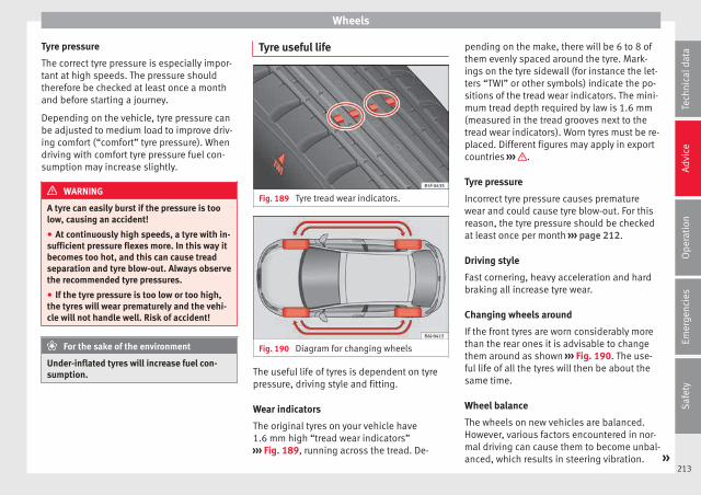
Wheels
Tyre pressure
The correct tyre pressure is especially impor-tant at high speeds. The pressure shouldtherefore be checked at least once a monthand before starting a journey.
Depending on the vehicle, tyre pressure canbe adjusted to medium load to improve driv-ing comfort (“comfort” tyre pressure). Whendriving with comfort tyre pressure fuel con-sumption may increase slightly.
WARNING
A tyre can easily burst if the pressure is toolow, causing an accident!
● At continuously high speeds, a tyre with in-sufficient pressure flexes more. In this way itbecomes too hot, and this can cause treadseparation and tyre blow-out. Always observethe recommended tyre pressures.
● If the tyre pressure is too low or too high,the tyres will wear prematurely and the vehi-cle will not handle well. Risk of accident!
For the sake of the environment
Under-inflated tyres will increase fuel con-sumption.
Tyre useful life
Fig. 189 Tyre tread wear indicators.
Fig. 190 Diagram for changing wheels
The useful life of tyres is dependent on tyrepressure, driving style and fitting.
Wear indicators
The original tyres on your vehicle have1.6 mm high “tread wear indicators”››› Fig. 189, running across the tread. De-
pending on the make, there will be 6 to 8 ofthem evenly spaced around the tyre. Mark-ings on the tyre sidewall (for instance the let-ters “TWI” or other symbols) indicate the po-sitions of the tread wear indicators. The mini-mum tread depth required by law is 1.6 mm(measured in the tread grooves next to thetread wear indicators). Worn tyres must be re-placed. Different figures may apply in exportcountries ››› .
Tyre pressure
Incorrect tyre pressure causes prematurewear and could cause tyre blow-out. For thisreason, the tyre pressure should be checkedat least once per month ››› page 212.
Driving style
Fast cornering, heavy acceleration and hardbraking all increase tyre wear.
Changing wheels around
If the front tyres are worn considerably morethan the rear ones it is advisable to changethem around as shown ››› Fig. 190. The use-ful life of all the tyres will then be about thesame time.
Wheel balance
The wheels on new vehicles are balanced.However, various factors encountered in nor-mal driving can cause them to become unbal-anced, which results in steering vibration. »
213
Tech
nica
l dat
aA
dvic
eO
pera
tion
Emer
genc
ies
Saf
ety

Advice
Unbalanced wheels should be rebalanced, asthey otherwise cause excessive wear onsteering, suspension and tyres. A wheel mustalso be rebalanced when a new tyre is fitted.
Incorrect wheel alignment
Incorrect wheel alignment causes excessivetyre wear, impairing the safety of the vehicle.If tyres show excessive wear, you shouldhave the wheel alignment checked by a Tech-nical Service.
WARNING
There is a serious danger of accidents if a tyrebursts during driving!
● The tyres must be replaced at the latestwhen the tread wear indicators are worn››› page 213. Failure to follow this instructioncould result in an accident. Worn tyres do notgrip well at high speeds on wet roads. Thereis also a greater risk of “aquaplaning”.
● At continuously high speeds, a tyre with in-sufficient pressure flexes more. This causes itto overheat. This can cause tread separationand tyre blow-out. Risk of accident. Alwaysobserve the recommended tyre pressures.
● If tyres show excessive wear, you shouldhave the running gear checked by a TechnicalService.
● Keep chemicals such as oil, fuel and brakefluid away from tyres.
● Damaged wheels and tyres must be re-placed immediately!
For the sake of the environment
Under-inflated tyres will increase fuel con-sumption.
New tyres and wheels
New tyres and wheels have to be run in.
The tyres and wheel rims are an essentialpart of the vehicle's design. Those approvedby SEAT are specially matched to the charac-teristics of the vehicle and make a major con-tribution to good road-holding and safe han-dling ››› .
Tyres should be replaced at least in pairs andnot individually (i.e. both front tyres or bothrear tyres together). A knowledge of tyre des-ignations makes it easier to choose the cor-rect tyres. Radial tyres have the tyre designa-tions marked on the sidewall, for example:
195/65 R15 91TThis contains the following information:
Tyre width in mm
Height/width ratio in %
Tyre construction: Radial
Rim diameter in inches
Load rating code
Speed rating
195
65
R
15
91
T
The tyres could also have the following infor-mation:
● A direction of rotation symbol
● “Reinforced” denotes heavy-duty tyres.
The manufacturing date is also indicated onthe tyre sidewall (possibly only on the innerside of the wheel).
“DOT ... 1103 ...” means, for example, thatthe tyre was produced in the 11th week of2003.
We recommend that work on tyres andwheels be carried out by a Technical Service.They are familiar with the procedure andhave the necessary special tools and spareparts as well as the proper facilities for dis-posing of the old tyres.
Any technical service has full information onthe technical requirements when installing orchanging tyres, wheels or wheel trims.
Note for Italy: A SEAT Service Centre shouldbe consulted whether different sized wheelsor tyres to those originally fitted by SEAT maybe fitted, as well as the combinations al-lowed between the front axle (axle 1) andback axle (axle 2).
WARNING
● We recommend that you use only wheelsand tyres which have been approved by SEAT
214

Wheels
for your model. Failure to do so could impairvehicle handling. Risk of accident.
● Avoid running the vehicle on tyres that aremore than 6 years old. If you have no alterna-tive, you should drive slowly and with extracare at all times.
● Never use old tyres or those with an un-known “history of use”.
● If wheel trims are retrofitted, you must en-sure that the flow of air to the brakes is notrestricted. This could cause the brake systemto overheat.
● All four wheels must be fitted with radialtyres of the same type, size (rolling circumfer-ence) and the same tread pattern.
For the sake of the environment
Old tyres must be disposed of according tothe laws in the country concerned.
Note
● For technical reasons, it is not generallypossible to use the wheels from other vehi-cles. This can also apply to wheels of thesame model. The use of wheels or tyreswhich have not been approved by SEAT foruse with your model may invalidate the vehi-cle's type approval for use on public roads.
● If the spare tyre is not the same as thetyres that are mounted on the vehicle (e.g.winter tyres) you should only use the sparetyre for a short period of time and drive with
extra care. Refit the normal road wheel assoon as possible.
Wheel bolts
The design of wheel bolts is matched to therims. If different wheel rims are fitted, thecorrect wheel bolts with the right length andcorrectly shaped bolt heads must be used.This ensures that wheels are fitted securelyand that the brake system functions correctly.
In certain circumstances, you should not usewheel bolts from a different vehicle, even if itis the same model ››› page 190.
WARNING
If the wheel bolts are not tightened correctly,the wheel could become loose while driving.Risk of accident.
● The wheel bolts must be clean and turneasily. Never apply grease or oil to them.
● Use only wheel bolts which belong to thewheel.
● If the prescribed torque of the wheel boltsis too low, they could loosen whilst the vehi-cle is in motion. Risk of accident! If the tight-ening torque is too high, the wheel bolts andthreads can be damaged.
CAUTION
The prescribed tightening torque for wheelbolts for steel and alloy wheels is 120 Nm.
Winter service
Winter tyres
In winter conditions winter tyres will consid-erably improve the vehicle's handling. Thedesign of summer tyres (width, rubber com-pound, tread pattern) gives less grip on iceand snow.
Winter tyres must be inflated to a pressure of0.2 bar (2.9 psi/20 kPa) higher than the pres-sures specified for summer tyres (see stickeron fuel tank flap).
Winter tyres must be fitted on all four wheels.
Information on permitted winter tyre sizescan be found in the vehicle's registrationdocumentation. Use only radial winter tyres.All tyre sizes listed in the vehicle documenta-tion also apply to winter tyres.
Winter tyres lose their effectiveness when thetread is worn down to a depth of 4 mm.
The speed rating code ››› page 214, Newtyres and wheels determines the followingspeed limits for winter tyres: ›››
max. 160 km/h (99 mph) »Q215
Tech
nica
l dat
aA
dvic
eO
pera
tion
Emer
genc
ies
Saf
ety

Advice
max. 180 km/h (112 mph)
max. 190 km/h (118 mph)
max. 210 km/h (130 mph)
In some countries, vehicles which can exceedthe speed rating of the fitted tyre must havean appropriate sticker in the driver's field ofview. These stickers are available from yourtechnical service. The legal requirements ofeach country must be followed.
Do not have winter tyres fitted for unnecessa-rily long periods. Vehicles with summer tyreshandle better when the roads are free ofsnow and ice.
If you have a flat tyre, please refer to thenotes on the spare wheel ››› page 214, Newtyres and wheels.
WARNING
The maximum speed for the winter tyres mustnot be exceeded. Otherwise, this could leadto damage and risk of accident.
For the sake of the environment
Fit your summer tyres again as soon as possi-ble. They are quieter, do not wear so quicklyand reduce fuel consumption.
S
T
H
216

Technical specifications
Technical data
Technical specifications
Important information
Important
The information in the vehicle documentationalways takes precedence over the informa-tion in this Instruction Manual.
All technical specifications provided in thisdocumentation are valid for the standardmodel in Spain. The vehicle data card inclu-ded in the Maintenance Programme or thevehicle registration documents shows whichengine is installed in the vehicle.
The figures may be different dependingwhether additional equipment is fitted, fordifferent models, for special vehicles and forother countries.
Abbreviations used in the technical specifi-cations section
kW Kilowatt, engine power measurement.
PSPferdestärke (horsepower), formerlyused to denote engine power.
rpm Revolutions per minute - engine speed.
Nm Newton metres, unit of engine torque.
litres per100 km
Fuel consumption in litres per 100 km(70 miles).
g/kmCarbon dioxide emissions in grams perkm (mile) travelled.
CO2 Carbon dioxide
CNCetane number, indication of the dieselcombustion power.
RONResearch octane number, indication ofthe knock resistance of petrol.
Vehicle identification data
Fig. 191 Vehicle data sticker (boot).
Fig. 192 Chassis number. »
217
Tech
nica
l dat
aA
dvic
eO
pera
tion
Emer
genc
ies
Saf
ety

Technical data
Vehicles for certain export countries do nothave an identification plate.
Identification plate
The identification plate is located on the rightrib inside the engine compartment.
Vehicle data sticker
The data sticker is placed on the inside of thespare wheel well, in the boot and on the rearcover of the Maintenance Programme.
The following information is provided on thevehicle data sticker: ››› Fig. 191
Vehicle identification number (chassisnumber)
Vehicle type, model, capacity, enginetype, finish, engine power and gearboxtype
Engine code, gearbox code, externalpaint code and internal equipment code
Optional extras and PR numbers
Consumption (l/100 km) and CO2 emis-sions (g/km)
A Urban cycle consumption
B Out-of-town consumption
C Combined consumption and CO2
emissions
1
2
3
4
5
Chassis number
The vehicle identification number can beread from outside the vehicle through a view-er in the windscreen ››› Fig. 192. The viewer islocated near the lower corner of the wind-screen. The chassis number is printed on theright water drain channel. The water drainchannel is located between the suspensionturret and the fender. To access the chassisnumber, open the bonnet ››› page 201.
Information on fuel consump-tion
Fuel consumption and CO2 emissions
The consumption and emission detailsshown on the vehicle data sticker differ fromone vehicle to another.
Vehicle fuel consumption and CO2 emissionsappear on the vehicle data sticker in thespare wheel well, inside the boot and on therear cover of the Maintenance Programme.
The fuel consumption and CO2 emission val-ues refer to the weight category assigned toyour vehicle according to the engine andgearbox combination, as well as the specificequipment fitted, and is only used to com-pare between the different models.
The fuel consumption and CO2 emissions donot depend only on the performance of thevehicle, they can also differ from the estab-lished values depending on other factorssuch as driving style, road conditions, trafficconditions, environmental conditions, loadand number of passengers.
Calculation of fuel consumption
The consumption values have been calcula-ted based on measurements performed orsupervised by certified CE laboratories ac-cording to the latest version of directives715/2007/EC and 80/1268/CEE (for more in-formation consult the European Union Publi-cations Office at EUR-Lex: © European Union,http://eur-lex.europa.eu/en/index.htm) andare valid for the kerb weight indicated for thevehicle.
Note
In practice, and considering all the factorsmentioned here, consumption values can dif-fer from those calculated in the current Euro-pean regulations.
Weights
Kerb weight refers to the basic model with afuel tank filled to 90% capacity and withoutoptional extras. The figure quoted includes75 kg to allow for the weight of the driver.
218
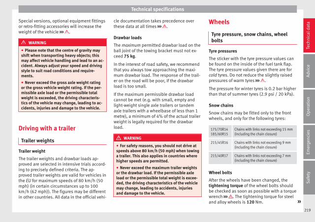
Technical specifications
Special versions, optional equipment fittingsor retro-fitting accessories will increase theweight of the vehicle ››› .
WARNING
● Please note that the centre of gravity mayshift when transporting heavy objects; thismay affect vehicle handling and lead to an ac-cident. Always adjust your speed and drivingstyle to suit road conditions and require-ments.
● Never exceed the gross axle weight ratingor the gross vehicle weight rating. If the per-missible axle load or the permissible totalweight is exceeded, the driving characteris-tics of the vehicle may change, leading to ac-cidents, injuries and damage to the vehicle.
Driving with a trailer
Trailer weights
Trailer weight
The trailer weights and drawbar loads ap-proved are selected in intensive trials accord-ing to precisely defined criteria. The ap-proved trailer weights are valid for vehicles inthe EU for maximum speeds of 80 km/h (50mph) (in certain circumstances up to 100km/h (62 mph)). The figures may be differentin other countries. All data in the official vehi-
cle documentation takes precedence overthese data at all times ››› .
Drawbar loads
The maximum permitted drawbar load on theball joint of the towing bracket must not ex-ceed 75 kg.
In the interest of road safety, we recommendthat you always tow approaching the maxi-mum drawbar load. The response of the trail-er on the road will be poor, if the drawbarload is too small.
If the maximum permissible drawbar loadcannot be met (e.g. with small, empty andlight-weight single axle trailers or tandemaxle trailers with a wheelbase of less than 1metre), a minimum of 4% of the actual trailerweight is legally required for the drawbarload.
WARNING
● For safety reasons, you should not drive atspeeds above 80 km/h (50 mph) when towinga trailer. This also applies in countries wherehigher speeds are permitted.
● Never exceed the maximum trailer weightsor the drawbar load. If the permissible axleload or the permissible total weight is excee-ded, the driving characteristics of the vehiclemay change, leading to accidents, injuriesand damage to the vehicle.
Wheels
Tyre pressure, snow chains, wheelbolts
Tyre pressures
The sticker with the tyre pressure values canbe found on the inside of the fuel tank flap.The tyre pressure values given there are forcold tyres. Do not reduce the slightly raisedpressures of warm tyres ››› .
The pressure for winter tyres is 0.2 bar higherthan that of summer tyres (2.9 psi / 20 kPa).
Snow chains
Snow chains may be fitted only to the frontwheels, and only for the following tyres:
175/70R14185/60R15
Chains with links not exceeding 15 mm(including the chain closure)
215/45R16 Chains with links not exceeding 9 mm(including the chain closure)
215/40R17 Chains with links not exceeding 7 mm(including the chain closure)
Wheel bolts
After the wheels have been changed, thetightening torque of the wheel bolts shouldbe checked as soon as possible with a torquewrench ››› . The tightening torque for steeland alloy wheels is 120 Nm. »
219
Tech
nica
l dat
aA
dvic
eO
pera
tion
Emer
genc
ies
Saf
ety

Technical data
WARNING
● Check the tyre pressure at least once permonth. Checking the tyre pressure is very im-portant. If the tyre pressure is too high or toolow, there is an increased danger of accidents- particularly at high speeds.
● If the tightening torque of the wheel boltsis too low, they could loosen while the vehi-cle is in motion. Risk of accident! If the tight-ening torque is too high, the wheel bolts andthreads can be damaged.
Note
We recommend that you ask your TechnicalService for information about appropriatewheel, tyre and snow chain size.
220

Technical specifications
Engine data
Petrol engine 1.0 MPI 55 kW (75 PS)
Power output in kW (PS) at rpm Maximum torque (Nm at rpm) No. of cylinders/displacement (cm3) Fuel
55 (75)/6,200 95/3,000-4,300 3/999 Super 95 RON/Normal 91 RONa)
a) Slight power loss.
Performance IBIZAIBIZA
Start-StopIBIZA SC
IBIZA SCStart-Stop
IBIZA STIBIZA ST
Start-Stop
Top speed (km/h) 172 172 172 172 172 172
Acceleration from 0-80 km/h (seconds) 9.5 9.5 9.5 9.5 9.9 9.9
Acceleration from 0-100 km/h (seconds) 14.3 14.3 14.3 14.3 14.8 14.8
Weights (in kg)
Gross vehicle weight 1,530 1,540 1,530 1,540 1,570 1,570
Weight in running order (with driver) 1,043 1,049 1,043 1,049 1,093 1,099
Gross front axle weight 790 800 790 800 790 800
Gross rear axle weight 790 790 790 790 830 820
Permitted roof load 75 75 75 75 75 75
Maximum trailer weights (in kg)
Trailer without brakes 520 520 520 520 540 540
Trailer with brakes, gradients up to 8% 1,000 1,000 1,000 1,000 1,000 1,000
Trailer with brakes, gradients up to 12% 800 800 800 800 800 800
221
Tech
nica
l dat
aA
dvic
eO
pera
tion
Emer
genc
ies
Saf
ety

Technical data
Petrol engine 1.2 TSI 66 kW (90 PS)
Power output in kW (PS) at rpm Maximum torque (Nm at rpm) No. of cylinders/displacement (cm3) Fuel
66 (90)/4,400-5,400 160/1,400-3,500 4/1,197 Super 95 RON/Normal 91 RONa)
a) Slight power loss.
Performance IBIZA IBIZA SC IBIZA ST
Top speed (km/h) 184 184 184
Acceleration from 0-80 km/h (seconds) 7.0 7.0 7.3
Acceleration from 0-100 km/h (seconds) 10.7 10.7 11.1
Weights (in kg)
Gross vehicle weight 1,580 1,580 1,620
Weight in running order (with driver) 1,089 1,089 1,139
Gross front axle weight 840 840 840
Gross rear axle weight 790 790 830
Permitted roof load 75 75 75
Maximum trailer weights (in kg)
Trailer without brakes 540 540 560
Trailer with brakes, gradients up to 8% 1,100 1,100 1,100
Trailer with brakes, gradients up to 12% 1,000 1,000 1,000
222

Technical specifications
Petrol engine 1.6 MPI 66 kW (90 PS)
Power output in kW (PS) at rpm Maximum torque (Nm at rpm) No. of cylinders/displacement (cm3) Fuel
66 (90)/4,250-6,000 155/3,800-4,000 4/1,598 Super 95 RON/Normal 91 RONa)
a) Slight power loss.
Performance IBIZA IBIZA SC IBIZA ST
Top speed (km/h) 185 185 185
Acceleration from 0-80 km/h (seconds) 7.0 7.0 7.0
Acceleration from 0-100 km/h (seconds) 10.6 10.6 11
Weights (in kg)
Gross vehicle weight 1,570 1,570 1,610
Weight in running order (with driver) 1,079 1,079 1,129
Gross front axle weight 830 830 830
Gross rear axle weight 790 790 830
Permitted roof load 75 75 75
Maximum trailer weights (in kg)
Trailer without brakes 530 530 560
Trailer with brakes, gradients up to 8% 1,000 1,000 1,000
Trailer with brakes, gradients up to 12% 1,000 1,000 1,000
223
Tech
nica
l dat
aA
dvic
eO
pera
tion
Emer
genc
ies
Saf
ety

Technical data
Petrol engine 1.0 EcoTSI 70 kW (95 CV) Start-Stop
Power output in kW (PS) at rpm Maximum torque (Nm at rpm) No. of cylinders/displacement (cm3) Fuel
70 (95)/5,000-5,500 160/1,500-3,500 3/999 Super 95 RON/Normal 91 RONa)
a) Slight power loss.
Performance IBIZAIBIZA
ecomotiveIBIZA SC
IBIZA SCecomotive
IBIZA STIBIZA ST
ecomotive
Top speed (km/h) 187 191 187 191 187 181
Acceleration from 0-80 km/h (seconds) 6.9 6.9 6.9 6.9 7.2 7.2
Acceleration from 0-100 km/h (seconds) 10.4 10.4 10.4 10.4 10.8 10.8
Weights (in kg)
Gross vehicle weight 1,590 1,590 1,590 1,590 1,630 1,630
Weight in running order (with driver) 1,095 1,095 1,095 1,095 1,145 1,145
Gross front axle weight 850 850 850 850 850 850
Gross rear axle weight 790 790 790 790 830 830
Permitted roof load 75 75 75 75 75 75
Maximum trailer weights (in kg)
Trailer without brakes 540 500 540 500 570 500
Trailer with brakes, gradients up to 8% 1000 500 1000 500 1000 500
Trailer with brakes, gradients up to 12% 900 500 900 500 900 500
224

Technical specifications
Petrol engine 1.0 EcoTSI 81 kW (110 CV) Start-Stop
Power output in kW (PS) at rpm Maximum torque (Nm at rpm) No. of cylinders/displacement (cm3) Fuel
81 (110)/5,000-5,500 200/2,000-3,500 3/999 Super 95 RON/Normal 91 RONa)
a) Slight power loss.
PerformanceIBIZA
ManualIBIZA
AutomaticIBIZA SCManual
IBIZA SCAutomatic
IBIZA STManual
IBIZA STAutomatic
Top speed (km/h) 196 197 196 197 196 197
Acceleration from 0-80 km/h (seconds) 6.3 6.2 6.3 6.2 6.5 6.4
Acceleration from 0-100 km/h (seconds) 9.2 9.3 9.2 9.3 9.6 9.5
Weights (in kg)
Gross vehicle weight 1,600 1,630 1,600 1,630 1,640 1,670
Weight in running order (with driver) 1,109 1,140 1,109 1,140 1,155 1,165
Gross front axle weight 860 900 860 900 860 900
Gross rear axle weight 790 780 790 780 830 820
Permitted roof load 75 75 75 75 75 75
Maximum trailer weights (in kg)
Trailer without brakes 550 570 550 570 570 580
Trailer with brakes, gradients up to 8% 1,100 1,100 1,100 1,100 1,100 1,100
Trailer with brakes, gradients up to 12% 1,000 1,000 1,000 1,000 1,000 1,000
225
Tech
nica
l dat
aA
dvic
eO
pera
tion
Emer
genc
ies
Saf
ety

Technical data
Petrol engine 1.2 TSI 81 kW (110 PS)
Power output in kW (PS) at rpm Maximum torque (Nm at rpm) No. of cylinders/displacement (cm3) Fuel
81 (110)/4,600-5,600 175/1,400-4,000 4/1,197 Super 95 RON/Normal 91 RONa)
a) Slight power loss.
Performance IBIZA IBIZA SC IBIZA ST
Top speed (km/h) 197 197 197
Acceleration from 0-80 km/h (seconds) 6.2 6.2 6.5
Acceleration from 0-100 km/h (seconds) 9.1 9.1 9.7
Weights (in kg)
Gross vehicle weight 1,590 1,590 1,630
Weight in running order (with driver) 1,102 1,102 1,152
Gross front axle weight 860 860 850
Gross rear axle weight 780 780 830
Permitted roof load 75 75 75
Maximum trailer weights (in kg)
Trailer without brakes 550 550 570
Trailer with brakes, gradients up to 8% 1,100 1,100 1,100
Trailer with brakes, gradients up to 12% 1,100 1,000 1,100
226

Technical specifications
Petrol engine 1.6 MPI 81 kW (110 PS)
Power output in kW (PS) at rpm Maximum torque (Nm at rpm) No. of cylinders/displacement (cm3) Fuel
81 (110)/5,800 155/3,800-4,000 4/1,598 Super 95 RON/Normal 91 RONa)
a) Slight power loss.
PerformanceIBIZA
ManualIBIZA
AutomaticIBIZA SCManual
IBIZA SCAutomatic
IBIZA STManual
IBIZA STAutomatic
Top speed (km/h) 196 197 196 197 196 197
Acceleration from 0-80 km/h (seconds) 6.4 a) 6.4 a) 7.0 a)
Acceleration from 0-100 km/h (seconds) 9.8 a) 9.8 a) 10.1 a)
Weights (in kg)
Gross vehicle weight 1,580 1,620 1,580 1,620 1,620 1,660
Weight in running order (with driver) 1,085 1,126 1,085 1,126 1,135 1,176
Gross front axle weight 840 890 840 890 840 880
Gross rear axle weight 790 780 790 780 830 830
Permitted roof load 75 75 75 75 75 75
Maximum trailer weights (in kg)
Trailer without brakes 540 560 540 560 560 580
Trailer with brakes, gradients up to 8% 1,100 1,100 1,100 1,100 1,100 1,100
Trailer with brakes, gradients up to 12% 1,100 1,100 1,100 1,100 1,100 1,100
a) Data not available as this edition goes to print.
227
Tech
nica
l dat
aA
dvic
eO
pera
tion
Emer
genc
ies
Saf
ety

Technical data
Petrol engine 1.4 EcoTSI ACT 110 kW (150 CV) Start-Stop
Power output in kW (PS) at rpm Maximum torque (Nm at rpm) No. of cylinders/displacement (cm3) Fuel
110 (150)/5,000-6,000 250/1,500-3,500 4/1,395 Super 95 RON/Normal 91 RONa)
a) Slight power loss.
Performance IBIZA IBIZA SC IBIZA ST
Top speed (km/h) 220 220 220
Acceleration from 0-80 km/h (seconds) 5.3 5.3 5.5
Acceleration from 0-100 km/h (seconds) 7.6 7.6 7.8
Weights (in kg)
Gross vehicle weight 1,630 1,630 1,670
Weight in running order (with driver) 1,143 1,143 1,165
Gross front axle weight a) a) a)
Gross rear axle weight a) a) a)
Permitted roof load 75 75 75
Maximum trailer weights (in kg)
Trailer without brakes 570 570 580
Trailer with brakes, gradients up to 8% 1,200 1,200 1,200
Trailer with brakes, gradients up to 12% 1,200 1,200 1,200
a) Data not available as this edition goes to print.
228

Technical specifications
Petrol engine 1.8 TSI 141 kW (192 PS) Start-Stop
Power output in kW (PS) at rpm Maximum torque (Nm at rpm) No. of cylinders/displacement (cm3) Fuel
141 (192)/4,300-6,200 320/1,450-4,200 4/1,798 Super 95 RON/Normal 91 RONa)
a) Slight power loss.
Performance IBIZA SC
Top speed (km/h) 235
Acceleration from 0-80 km/h (seconds) 5.1
Acceleration from 0-100 km/h (seconds) 6.7
Weights (in kg)
Gross vehicle weight 1,700
Weight in running order (with driver) 1,263
Gross front axle weight a)
Gross rear axle weight a)
Permitted roof load 75
Maximum trailer weights (in kg)
Trailer without brakes –
Trailer with brakes, gradients up to 8% –
Trailer with brakes, gradients up to 12% –
a) Data not available as this edition goes to print.
229
Tech
nica
l dat
aA
dvic
eO
pera
tion
Emer
genc
ies
Saf
ety

Technical data
Diesel engine 1.4 TDI 55 kW (75 PS)
Power output in kW (PS) at rpm Maximum torque (Nm at rpm) No. of cylinders/displacement (cm3) Fuel
55 (75)/3,000-3,750 210/1,500-2,000 3/1,422 Min, diesel acc. to DIN EN 590 51 CN
Performance IBIZAIBIZA
Start-StopIBIZA SC
IBIZA SCStart-Stop
IBIZA STIBIZA ST
Start-Stop
Top speed (km/h) 173 171 173 171 173 171
Acceleration from 0-80 km/h (seconds) 8.6 8.5 8.6 8.5 9.3 8.8
Acceleration from 0-100 km/h (seconds) 12.9 13.0 12.9 13.0 14.3 13.5
Weights (in kg)
Gross vehicle weight 1,640 1,630 1,640 1,640 1,680 1,680
Weight in running order (with driver) 1,150 1,155 1,150 1,155 1,200 1,205
Gross front axle weight 900 910 900 910 900 910
Gross rear axle weight 790 770 790 770 830 820
Permitted roof load 75 75 75 75 75 75
Maximum trailer weights (in kg)
Trailer without brakes 570 570 570 570 600 600
Trailer with brakes, gradients up to 8% 1,100 1,100 1,100 1,100 1,100 1,100
Trailer with brakes, gradients up to 12% 1,000 1,000 1,000 1,000 1,000 1,000
230

Technical specifications
Diesel engine 1.4 TDI 66 kW (90 PS)
Power output in kW (PS) at rpm Maximum torque (Nm at rpm) No. of cylinders/displacement (cm3) Fuel
66 (90)/2,750-3,500 230/1,500-2,500 3/1,422 Min, diesel acc. to DIN EN 590 51 CN
Performance IBIZAIBIZA
Start-StopIBIZA
AutomaticIBIZA SC
IBIZA SCStart-Stop
IBIZA SCAutomatic
IBIZA STIBIZA ST
Start-StopIBIZA ST
Automatic
Top speed (km/h) 182 182 182 182 182 182 182 182 182
Acceleration from 0-80 km/h (sec-onds)
7.4 7.4 7.4 7.4 7.4 7.4 7.6 7.6 7.7
Acceleration from 0-100 km/h(seconds)
10.9 10.9 10.9 10.9 10.9 10.9 11.3 11.3 11.4
Weights (in kg)
Gross vehicle weight 1,640 1,640 1,670 1,640 1,640 1,670 1,680 1,680 1,710
Weight in running order (with driv-er)
1,150 1,155 1,165 1,150 1,155 1,165 1,200 1,205 1,233
Gross front axle weight 900 910 a) 900 910 a) 900 910 a)
Gross rear axle weight 790 780 a) 790 780 a) 830 820 a)
Permitted roof load 75 75 75 75 75 75 75 75 75
Maximum trailer weights (in kg)
Trailer without brakes 570 570 580 570 570 580 600 600 610
Trailer with brakes, gradients upto 8%
1,200 1,200 1,200 1,200 1,200 1,200 1,200 1,200 1,200
Trailer with brakes, gradients upto 12%
1,100 1,100 1,100 1,100 1,100 1,100 1,100 1,100 1,100
a) Data not available as this edition goes to print.
231
Tech
nica
l dat
aA
dvic
eO
pera
tion
Emer
genc
ies
Saf
ety

Technical data
Diesel engine 1.4 TDI 77 kW (105 PS) Start-Stop
Power output in kW (PS) at rpm Maximum torque (Nm at rpm) No. of cylinders/displacement (cm3) Fuel
77 (105)/3,500-3,750 250/1,750-2,500 3/1,422 Min, diesel acc. to DIN EN 590 51 CN
Performance IBIZA IBIZA SC IBIZA ST
Top speed (km/h) 192 192 192
Acceleration from 0-80 km/h (seconds) 6.9 6.9 7.2
Acceleration from 0-100 km/h (seconds) 9.9 9.9 10.3
Weights (in kg)
Gross vehicle weight 1,650 1,650 1,690
Weight in running order (with driver) 1,161 1,161 1,211
Gross front axle weight 920 920 910
Gross rear axle weight 780 780 830
Permitted roof load 75 75 75
Maximum trailer weights (in kg)
Trailer without brakes 580 580 600
Trailer with brakes, gradients up to 8% 1,200 1,200 1,200
Trailer with brakes, gradients up to 12% 1,100 1,100 1,100
232

Technical specifications
Dimensions
Fig. 193 Dimensions
IBIZA IBIZA SC IBIZA ST
A/B Front and rear projections (mm) 857/735 857/717 857/910
C Wheelbase (mm) 2,469 2,469 2,469
D Length (mm) 4,061 4,043 4,236
E/F Front/reara) track width (mm) 1,465/1,457 1,465/1,457 1,465/1,457
G Width (mm) 1,693 1,693 1,693
H Height at kerb weight (mm) 1,445 1,428 1,445
Turning radius (m) 10.7 10.7 10.7
a) This data will change depending on the type of wheel rim.
233
Tech
nica
l dat
aA
dvic
eO
pera
tion
Emer
genc
ies
Saf
ety


Index
Index
AABS . . . . . . . . . . . . . . . . . . . . . . . . . . . . . . . . . . . . 171
control lamp . . . . . . . . . . . . . . . . . . . . . . . . . . . 102Accessories . . . . . . . . . . . . . . . . . . . . . . . . . . . . . . 190Additional electrical appliances (efficiency pro-
gramme) . . . . . . . . . . . . . . . . . . . . . . . . . . . . . . . 31Adjusting
front head restraints . . . . . . . . . . . . . . . . . . . . . 133lights . . . . . . . . . . . . . . . . . . . . . . . . . . . . . . . . . 125rear head restraints . . . . . . . . . . . . . . . . . . . . . . 60
Adjusting the front seatsadjusting the lumbar support . . . . . . . . . . . . . 132
Adjusting the head restraintsfront head restraints . . . . . . . . . . . . . . . . . . . . . 133rear head restraints . . . . . . . . . . . . . . . . . . . . . . 60
Adjusting the seat . . . . . . . . . . . . . . . . . . . . . . . . 132Adjustment
CAR menu . . . . . . . . . . . . . . . . . . . . . . . . . . . . . 107front head restraints . . . . . . . . . . . . . . . . . . . . . . 60seats . . . . . . . . . . . . . . . . . . . . . . . . . . . . . . . . . . 57
AFS headlight bulbs . . . . . . . . . . . . . . . . . . . . . . . . 87Airbag covers . . . . . . . . . . . . . . . . . . . . . . . . . . . . . 14Airbag system . . . . . . . . . . . . . . . . . . . . . . . . . . 14, 66
activation . . . . . . . . . . . . . . . . . . . . . . . . . . . . . . 68control lamp . . . . . . . . . . . . . . . . . . . . . . . . . . . . 68deactivation of front airbag . . . . . . . . . . . . . . . . 70description . . . . . . . . . . . . . . . . . . . . . . . . . . . . . 67front airbags . . . . . . . . . . . . . . . . . . . . . . . . . 14, 69functioning . . . . . . . . . . . . . . . . . . . . . . . . . . . . . 68head-protection airbags . . . . . . . . . . . . . . . . . . 15side airbags . . . . . . . . . . . . . . . . . . . . . . . . . . . . 15
Air conditioning . . . . . . . . . . . . . . . . . . . . . . 39, 148Climatronic . . . . . . . . . . . . . . . . . . . . . . . . . . . . 150controls . . . . . . . . . . . . . . . . . . . . . . . . . . . . . . . 148
General notes . . . . . . . . . . . . . . . . . . . . . . . . . . 144manual air conditioning . . . . . . . . . . . . . . . . . . . 40
Air outlets . . . . . . . . . . . . . . . . . . . . . . . . . . . . . . . 146Air recirculation
air conditioning . . . . . . . . . . . . . . . . . . . . . . . . 149heating and fresh air . . . . . . . . . . . . . . . . . . . . 147
Alarm system . . . . . . . . . . . . . . . . . . . . . . . . . . . . 118Switching off . . . . . . . . . . . . . . . . . . . . . . . . . . . 119
Alloy wheel rims . . . . . . . . . . . . . . . . . . . . . . . . . . 196Alternator
warning lamp . . . . . . . . . . . . . . . . . . . . . . . . . . 106Ambient lighting . . . . . . . . . . . . . . . . . . . . . . . . . 128Anti-freeze . . . . . . . . . . . . . . . . . . . . . . . . . . . . . . . 42Anti-lock brake system . . . . . . . . . . . . 103, 169, 171
control lamp . . . . . . . . . . . . . . . . . . . . . . . . . . . 102Anti-puncture kit . . . . . . . . . . . . . . . . . . . . 46, 76, 77
check after 10 minutes . . . . . . . . . . . . . . . . . . . . 78Anti-theft alarm system . . . . . . . . . . . . . . . . . . . . 118
Switching off . . . . . . . . . . . . . . . . . . . . . . . . . . . 119Aquaplaning . . . . . . . . . . . . . . . . . . . . . . . . . . . . . 214Aspects to note before setting off . . . . . . . . . . . . . 56ASR . . . . . . . . . . . . . . . . . . . . . . . . . . . . . . . . . . . . 172
control lamp . . . . . . . . . . . . . . . . . . . . . . . . . . . 103Assistance systems
parking aid . . . . . . . . . . . . . . . . . . . . . . . 176, 177Assistance Systems
tiredness detection . . . . . . . . . . . . . . . . . . . . . 175Assisted starting . . . . . . . . . . . . . . . . . . . . . . . . . . 52Audible warning signal
seat belt not fastened . . . . . . . . . . . . . . . . . . . . 62warning and indication lamps . . . . . . . . . . . . . 100
Automatic car wash tunnel . . . . . . . . . . . . . . . . . 192Automatic gearbox . . . . . . . . . . . . . . . . . . . . . . . . 159
driving programmes . . . . . . . . . . . . . . . . . . . . . 159Driving tips . . . . . . . . . . . . . . . . . . . . . . . . . . . . 163kick-down device . . . . . . . . . . . . . . . . . . . . . . . 164manual release of selector lever . . . . . . . . . . . . 38
selecting gears with Tiptronic . . . . . . . . . . . . . 162selector lever lock . . . . . . . . . . . . . . . . . . . . . . . 161selector lever positions . . . . . . . . . . . . . . . . . . 160tiptronic . . . . . . . . . . . . . . . . . . . . . . . . . . . . . . . 159
Automatic lighting . . . . . . . . . . . . . . . . . . . . . . . . 124AUX-IN . . . . . . . . . . . . . . . . . . . . . . . . . . . . . . . . . . 112
BBack seat
folding down and raising the back seat back-rest . . . . . . . . . . . . . . . . . . . . . . . . . . . . . . . . . 135
Ball coupling . . . . . . . . . . . . . . . . . . . . . . . . . . . . . 188Battery . . . . . . . . . . . . . . . . . . . . . . . . . . . . . . . . . . 117Before setting off . . . . . . . . . . . . . . . . . . . . . . . . . . 56Belt pretensioners . . . . . . . . . . . . . . . . . . . . . . . . . 65Biodiesel . . . . . . . . . . . . . . . . . . . . . . . . . . . . . . . . 201Bonnet . . . . . . . . . . . . . . . . . . . . . . . . . 10, 201, 204
closing . . . . . . . . . . . . . . . . . . . . . . . . . . . . . . . . 203opening . . . . . . . . . . . . . . . . . . . . . . . . . . . . . . . 203
Boot hatch . . . . . . . . . . . . . . . . . . . . . . . . . . . . . . 120Boot lid . . . . . . . . . . . . . . . . . . . . . . . . . . . . . . . . . 120Brake assist . . . . . . . . . . . . . . . . . . . . . . . . . . . . . 103Brake fluid . . . . . . . . . . . . . . . . . . . . . . . . . . 43, 208
Changing . . . . . . . . . . . . . . . . . . . . . . . . . . . . . . 208Brake pads . . . . . . . . . . . . . . . . . . . . . . . . . 156, 165Brakes . . . . . . . . . . . . . . . . . . . . . . . . . . . . . . . . . . 208
brake fluid . . . . . . . . . . . . . . . . . . . . . . . . . . . . . 208new Brake pads . . . . . . . . . . . . . . . . . . . . . . . . 156warning lamp . . . . . . . . . . . . . . . . . . . . . . . . . . 104
Brake servo . . . . . . . . . . . . . . . . . . . . . . . . . 156, 173Braking
brake assist . . . . . . . . . . . . . . . . . . . . . . . . . . . . 103Braking distance . . . . . . . . . . . . . . . . . . . . . . . . . 156Bulbs
changing a bulb . . . . . . . . . . . . . . . . . . . . . . . . . 83Buzzer . . . . . . . . . . . . . . . . . . . . . . . . . . . . . . . . . . 126
235

Index
CCapacities . . . . . . . . . . . . . . . . . . . . . . . . . . . . . . . . 40
fuel tank . . . . . . . . . . . . . . . . . . . . . . . . . . . . . . 100Car care
Exterior . . . . . . . . . . . . . . . . . . . . . . . . . . . . . . . 192Catalytic converter . . . . . . . . . . . . . . . . . . . . . . . . 166CCS . . . . . . . . . . . . . . . . . . . . . . . . . . . . . . . . . . . . . 34Central locking
anti-theft alarm . . . . . . . . . . . . . . . . . . . . . . . . . 118automatic speed-dependent locking . . . . . . . 114central locking button . . . . . . . . . . . . . . . . . . . 115electric windows . . . . . . . . . . . . . . . . . . . . . . . . 122key by remote control . . . . . . . . . . . . . . . . . . . . 117Selective unlocking system . . . . . . . . . . . . . . . 113self-locking system to prevent involuntary un-
locking . . . . . . . . . . . . . . . . . . . . . . . . . . . . . . 114unlocking system . . . . . . . . . . . . . . . . . . . . . . . 114
Central locking system . . . . . . . . . . . . . . . . . . . . . 112Safe security system . . . . . . . . . . . . . . . . . . . . 112
Cetane number . . . . . . . . . . . . . . . . . . . . . . . . . . . 200Changing a
DRL light bulb . . . . . . . . . . . . . . . . . . . . . . . . . . . 84Changing a bulb
additional brake light . . . . . . . . . . . . . . . . . . . . . 92AFS headlight bulbs . . . . . . . . . . . . . . . . . . . . . . 87fog light bulbs . . . . . . . . . . . . . . . . . . . . . . . . . . 88general notes . . . . . . . . . . . . . . . . . . . . . . . . . . . 83interior light and reading light . . . . . . . . . . . . . 92luggage compartment light . . . . . . . . . . . . . . . . 93number plate light . . . . . . . . . . . . . . . . . . . . . . . 92tail light bulb on the rear lid . . . . . . . . . . . . . . . 91tail light bulb on the side panel . . . . . . . . . . . . 90tail light bulbs . . . . . . . . . . . . . . . . . . . . . . . . . . . 89turn signal light . . . . . . . . . . . . . . . . . . . . . . . . . 87Turn signals . . . . . . . . . . . . . . . . . . . . . . . . . . . . . 91
Changing a double headlight bulbdipped beam headlights . . . . . . . . . . . . . . . . . . 86double headlight bulbs . . . . . . . . . . . . . . . . . . . 85
Changing an AFS headlight bulb . . . . . . . . . . . . . . 87turn signal light . . . . . . . . . . . . . . . . . . . . . . . . . 87xenon light . . . . . . . . . . . . . . . . . . . . . . . . . . . . . 87
Changing a single headlight bulbside light . . . . . . . . . . . . . . . . . . . . . . . . . . . . . . . 85single headlight bulbs . . . . . . . . . . . . . . . . . . . . 84turn signal light . . . . . . . . . . . . . . . . . . . . . . . . . 84
Changing a wheel . . . . . . . . . . . . . . . . . . . . . . . . . 47subsequent work . . . . . . . . . . . . . . . . . . . . . . . . 50
Changing double headlight bulbside light . . . . . . . . . . . . . . . . . . . . . . . . . . . . . . . 86
Changing settingsCAR menu . . . . . . . . . . . . . . . . . . . . . . . . . . . . . . 24
Changing the blades . . . . . . . . . . . . . . . . . . . . . . . 78Changing the double headlight bulb
main beam . . . . . . . . . . . . . . . . . . . . . . . . . . . . . 86Changing the single headlight bulbs
dipped/main beam . . . . . . . . . . . . . . . . . . . . . . 85Charging the battery . . . . . . . . . . . . . . . . . . . . . . . 52Checking levels
engine compartment . . . . . . . . . . . . . . . . . . . . 204Child-proof locking
electric windows . . . . . . . . . . . . . . . . . . . . . . . . 120Child seat
Categorisation in groups . . . . . . . . . . . . . . . . . . 73Child seats . . . . . . . . . . . . . . . . . . . . . . . . . . . . 16, 73
ISOFIX system . . . . . . . . . . . . . . . . . . . . . . . . . . . 18safety instructions . . . . . . . . . . . . . . . . . . . . 16, 72Securing with the seat belt . . . . . . . . . . . . . . . . 17Top Tether system . . . . . . . . . . . . . . . . . . . . . 18, 20
Chrome partscleaning . . . . . . . . . . . . . . . . . . . . . . . . . . . . . . 195
Cigarette lighter . . . . . . . . . . . . . . . . . . . . . . . . . . 138
Cleaning . . . . . . . . . . . . . . . . . . . . . . . . . . . . . . . . 191alloy wheel rims . . . . . . . . . . . . . . . . . . . . . . . . 196chrome parts . . . . . . . . . . . . . . . . . . . . . . . . . . . 195cleaning of windows and exterior mirrors . . . . 194engine compartment . . . . . . . . . . . . . . . . . . . . 196fabric . . . . . . . . . . . . . . . . . . . . . . . . . . . . . . . . . 197high pressure cleaners . . . . . . . . . . . . . . . . . . . 193leather . . . . . . . . . . . . . . . . . . . . . . . . . . . . . . . . 197plastic parts . . . . . . . . . . . . . . . . . . . . . . 194, 197radio and climate controls . . . . . . . . . . . . . . . . 197rubber seals . . . . . . . . . . . . . . . . . . . . . . . . . . . 195seat belts . . . . . . . . . . . . . . . . . . . . . . . . . . . . . 198steel wheel rims . . . . . . . . . . . . . . . . . . . . . . . . 195upholstery . . . . . . . . . . . . . . . . . . . . . . . . . . . . . 197washing the vehicle . . . . . . . . . . . . . . . . . . . . . 192windscreen wiper blades . . . . . . . . . . . . . . . . . 195wooden trim . . . . . . . . . . . . . . . . . . . . . . . . . . . 197
Climatronic . . . . . . . . . . . . . . . . . . . . . . . . . . . . . . . 39adjusting the temperature . . . . . . . . . . . . . . . . 151air recirculation . . . . . . . . . . . . . . . . . . . . . . . . . 152automatic mode . . . . . . . . . . . . . . . . . . . . . . . . 151blower selection . . . . . . . . . . . . . . . . . . . . . . . . 152controls . . . . . . . . . . . . . . . . . . . . . . . . . . . . . . . 150general notes . . . . . . . . . . . . . . . . . . . . . . . . . . 144windscreen defrost . . . . . . . . . . . . . . . . . . . . . . 152
Closing . . . . . . . . . . . . . . . . . . . . . . . . . . . . . . . . . 112bonnet . . . . . . . . . . . . . . . . . . . . . . . . . . . . . . . . 203tilting panoramic sunroof . . . . . . . . . . . . . . . . 122windows . . . . . . . . . . . . . . . . . . . . . . . . . . . . . . 120
Coming Home Function . . . . . . . . . . . . . . . . . . . . 126Contact key . . . . . . . . . . . . . . . . . . . . . . . . . . . . . . 153Controls and displays
general instrument panel . . . . . . . . . . . . . . . . . . 95Controls on the steering wheel
operating the audio system . . . . . . . . . . . . . . . 109operating the audio system and telephone . . 110
236

Index
Convenience closingtilting panoramic sunroof . . . . . . . . . . . . . . . . 123windows . . . . . . . . . . . . . . . . . . . . . . . . . . . . . . 122
Convenience openingwindows . . . . . . . . . . . . . . . . . . . . . . . . . . . . . . 122
Coolantchecking level . . . . . . . . . . . . . . . . . . . . . . . . . . 207
Coolant levelcontrol lamp . . . . . . . . . . . . . . . . . . . . . . . . . . . 106
Coolant temperaturecontrol lamp . . . . . . . . . . . . . . . . . . . . . . . . . . . 106Safety instructions . . . . . . . . . . . . . . . . . . . . . . 106
Cooling systemchecking coolant . . . . . . . . . . . . . . . . . . . . . . . 207Coolant temperature gauge . . . . . . . . . . . . . . . . 99topping up coolant . . . . . . . . . . . . . . . . . . . . . . 207
Correct position . . . . . . . . . . . . . . . . . . . . . . . . . . . 57Correct sitting position
front passenger . . . . . . . . . . . . . . . . . . . . . . . . . 58rear seat passengers . . . . . . . . . . . . . . . . . . . . . 59
Cruise control . . . . . . . . . . . . . . . . . . . . . . . . 34, 184adjusting the stored speed . . . . . . . . . . . . . . . 184complete deactivation . . . . . . . . . . . . . . . . . . . 185control lamp . . . . . . . . . . . . . . . . . . . . . . . . . . . 184temporary deactivation . . . . . . . . . . . . . . . . . . 185
Cruise control systemcontrol lamp . . . . . . . . . . . . . . . . . . . . . . . . . . . 104
Cruise speedcontrol lamp . . . . . . . . . . . . . . . . . . . . . . . . . . . 104
Current . . . . . . . . . . . . . . . . . . . . . . . . . . . . . . . . . 138
DDangers in not using the seat belt . . . . . . . . . . . . 63Dash panel . . . . . . . . . . . . . . . . . . . . . . . . . . . . . . . 35Data sticker . . . . . . . . . . . . . . . . . . . . . . . . . . . . . . 217Deactivating the front passenger front airbag . . . 14Deactivation of front airbag . . . . . . . . . . . . . . . . . . 70
Diesel . . . . . . . . . . . . . . . . . . . . . . . . . . . . . . . . . . 200Diesel engine
Winter operation . . . . . . . . . . . . . . . . . . . . . . . . 201Diesel engine particulate filter . . . . . . . . . . . . . . 166Differential lock fault (EDS)
control lamp . . . . . . . . . . . . . . . . . . . . . . . . . . . 103Digital clock . . . . . . . . . . . . . . . . . . . . . . . . . . . . . . 96Dimensions . . . . . . . . . . . . . . . . . . . . . . . . . . . . . . 233Direction of rotation
tyres . . . . . . . . . . . . . . . . . . . . . . . . . . . . . . . . . . . 49Display . . . . . . . . . . . . . . . . . . . . . . . . . . . . . . . 96, 97Disposal
Seat belt tensioners . . . . . . . . . . . . . . . . . . . . . . 66Door handle
de-icing . . . . . . . . . . . . . . . . . . . . . . . . . . . . . . . 195Door lock
de-icing . . . . . . . . . . . . . . . . . . . . . . . . . . . . . . . 195Door lock cylinder
de-icing . . . . . . . . . . . . . . . . . . . . . . . . . . . . . . . 195Door release lever . . . . . . . . . . . . . . . . . . . . . . . . . 95Doors
Childproof locks . . . . . . . . . . . . . . . . . . . . . . . . 115opening and closing . . . . . . . . . . . . . . . . . . . . . . 9
Double headlight bulbs . . . . . . . . . . . . . . . . . . . . . 85Driver
see Correct sitting position . . . . . . . . . 57, 58, 59Driver information system
additional electrical appliances . . . . . . . . . . . . 31assist systems . . . . . . . . . . . . . . . . . . . . . . . . . . 29bonnet, rear lid and doors open . . . . . . . . . . . . 28engine oil temperature . . . . . . . . . . . . . . . . . . . . 31gear-change indicator . . . . . . . . . . . . . . . . . . . . 28journey data . . . . . . . . . . . . . . . . . . . . . . . . . . . . 29menu . . . . . . . . . . . . . . . . . . . . . . . . . . . . . . . . . . 27operation . . . . . . . . . . . . . . . . . . . . . . . . . . . . . . . 25outside temperature . . . . . . . . . . . . . . . . . . . . . . 27saving tips . . . . . . . . . . . . . . . . . . . . . . . . . . . . . . 31
service intervals . . . . . . . . . . . . . . . . . . . . . . . . . 33speed warning . . . . . . . . . . . . . . . . . . . . . . . . . . 32timer . . . . . . . . . . . . . . . . . . . . . . . . . . . . . . . . . . 31warning and information messages . . . . . . . . . 29
Drivingdriving abroad . . . . . . . . . . . . . . . . . . . . . . . . . 168with a trailer . . . . . . . . . . . . . . . . . . 187, 188, 219
Driving abroadHeadlights . . . . . . . . . . . . . . . . . . . . . . . . . . . . 169petrol . . . . . . . . . . . . . . . . . . . . . . . . . . . . . . . . . 168
Driving assistance systemscruise control . . . . . . . . . . . . . . . . . . . . . . . . . . 184
Driving safety . . . . . . . . . . . . . . . . . . . . . . . . . . . . . 56Driving with a trailer . . . . . . . . . . . . . . . . . . . . . . . 187DSG . . . . . . . . . . . . . . . . . . . . . . . . . . . . . . . . . . . . 159Duplicate keys . . . . . . . . . . . . . . . . . . . . . . . . . . . 116Dust and pollen filter . . . . . . . . . . . . . . . . . . . . . . 144Dynamic headlight range control . . . . . . . . . . . . 125
EEasy Connect . . . . . . . . . . . . . . . . . . . . . . . . 24, 107Economic
driving . . . . . . . . . . . . . . . . . . . . . . . . . . . . . . . . 167EDL
see Electronic differential lock . . . . . . . . . . . . . 170EDS . . . . . . . . . . . . . . . . . . . . . . . . . . . . . . . . . . . . 170Efficiency programme
additional electrical appliances . . . . . . . . . . . . 31saving tips . . . . . . . . . . . . . . . . . . . . . . . . . . . . . . 31
Electrical power socket . . . . . . . . . . . . . . . . . . . . 138Electric windows . . . . . . . . . . . . . . . . . . . . . . 11, 120
convenience opening/closing . . . . . . . . . . . . . 122Electrolyte . . . . . . . . . . . . . . . . . . . . . . . . . . . . . . . 210Electronic differential lock . . . . . . . . . 103, 169, 170
control lamp . . . . . . . . . . . . . . . . . . . . . . 102, 103Electronic differential lock (XDS) . . . . . . . . . . . . . 173Electronic immobiliser . . . . . . . . . . . . . . . . 107, 154
237

Index
Electronic Stability Control . . . . . . . . . . . . . . . . . 170Electronic Stability Control (ESC) . . . . . . . 103, 169Emergencies . . . . . . . . . . . . . . . . . . . . . . . . . . . . . . 75
bulbs . . . . . . . . . . . . . . . . . . . . . . . . . . . . . . . . . . 45changing a wheel . . . . . . . . . . . . . . . . . . . . . . . . 47changing the battery . . . . . . . . . . . . . . . . . . . . 211emergency towing of the vehicle . . . . . . . . . . . . 51emergency warning triangle . . . . . . . . . . . . . . . 75fire extinguisher . . . . . . . . . . . . . . . . . . . . . . . . . 75first-aid kit . . . . . . . . . . . . . . . . . . . . . . . . . . . . . . 75fuses . . . . . . . . . . . . . . . . . . . . . . . . . . . . . . . . . . 44hazard warning lights . . . . . . . . . . . . . . . . . . . 127Jump leads . . . . . . . . . . . . . . . . . . . . . . . . . . . . . 52panoramic/tilting sunroof . . . . . . . . . . . . . . . . . 11puncture . . . . . . . . . . . . . . . . . . . . . . . . . . . . . . . 45replacing a blown fuse . . . . . . . . . . . . . . . . . . . . 44Spare wheel . . . . . . . . . . . . . . . . . . . . . . . . . . . . 76vehicle tools . . . . . . . . . . . . . . . . . . . . . . . . . . . . 75
Emergency operationselector lever . . . . . . . . . . . . . . . . . . . . . . . . . . . 38
Emergency warning triangle . . . . . . . . . . . . 75, 127Emission control system
control lamp . . . . . . . . . . . . . . . . . . . . . . . . . . . 106Emissions data . . . . . . . . . . . . . . . . . . . . . . . . . . . 217Engine
assisted starting . . . . . . . . . . . . . . . . . . . . . . . . . 52Running in . . . . . . . . . . . . . . . . . . . . . . . . . . . . . 165Start-Stop system . . . . . . . . . . . . . . . . . . . . . . . 173
Engine compartment . . . . . . . . . . . . . . 10, 201, 204battery . . . . . . . . . . . . . . . . . . . . . . . . . . . . . . . . 209brake fluid . . . . . . . . . . . . . . . . . . . . . . . . . . . . . 208closing . . . . . . . . . . . . . . . . . . . . . . . . . . . . . . . . 203coolant . . . . . . . . . . . . . . . . . . . . . . . . . . . . . . . 207engine oil . . . . . . . . . . . . . . . . . . . . . . . . . . . . . 206opening . . . . . . . . . . . . . . . . . . . . . . . . . . . . . . . 203safety notes . . . . . . . . . . . . . . . . . . . . . . . . . . . 201windscreen washer liquid . . . . . . . . . . . . . . . . 209
Engine coolant . . . . . . . . . . . . . . . . . . . . . . . . . . . . 42checking level . . . . . . . . . . . . . . . . . . . . . . . . . . 207G12 plus-plus . . . . . . . . . . . . . . . . . . . . . . . . . . . 42G13 . . . . . . . . . . . . . . . . . . . . . . . . . . . . . . . . . . . 42specifications . . . . . . . . . . . . . . . . . . . . . . . . . . . 42
Engine data . . . . . . . . . . . . . . . . . . . . . . . . . . . . . . 221Engine fault
control lamp . . . . . . . . . . . . . . . . . . . . . . . . . . . 101Engine management
control lamp . . . . . . . . . . . . . . . . . . . . . . . . . . . 101Engine oil . . . . . . . . . . . . . . . . . . . . . . . . . . . 41, 204
changing . . . . . . . . . . . . . . . . . . . . . . . . . 204, 206check oil level . . . . . . . . . . . . . . . . . . . . . . . . . . 206consumption . . . . . . . . . . . . . . . . . . . . . . . . . . . 206diesel . . . . . . . . . . . . . . . . . . . . . . . . . . . . . . . . . 204engine oil dipstick . . . . . . . . . . . . . . . . . . . . . . 206inspection service . . . . . . . . . . . . . . . . . . . . . . 204maintenance intervals . . . . . . . . . . . . . . . . . . . 204oil properties . . . . . . . . . . . . . . . . . . . . . . . . . . . 41Specifications . . . . . . . . . . . . . . . . . . . . . . . . . . 204temperature display . . . . . . . . . . . . . . . . . . . . . . 31topping up . . . . . . . . . . . . . . . . . . . . . . . . . . . . 206
Engine oil pressurewarning lamp . . . . . . . . . . . . . . . . . . . . . . . . . . 102
Environmentecological driving . . . . . . . . . . . . . . . . . . . . . . . 167Environmental compatibility . . . . . . . . . . . . . . 165
Environmental tipsrefuelling . . . . . . . . . . . . . . . . . . . . . . . . . . . . . . 199
Equipment . . . . . . . . . . . . . . . . . . . . . . . . . . . . . . 190ESC . . . . . . . . . . . . . . . . . . . . . . . . . . . . . . . 103, 170
electronic stability control . . . . . . . . . . . 103, 169Sport Mode . . . . . . . . . . . . . . . . . . . . . . . . . . . . 169see also Electronic Stability Control (ESC) . . . 170
Exhaust gas emission control system . . . . . . . . . 166Extending
the luggage compartment . . . . . . . . . . . . . . . . 135
Exterior lightingchanging a bulb . . . . . . . . . . . . . . . . . . . . . . . . . 83
Exterior mirrors . . . . . . . . . . . . . . . . . . . . . . . . . . . 131adjusting . . . . . . . . . . . . . . . . . . . . . . . . . . . . . . . 13control . . . . . . . . . . . . . . . . . . . . . . . . . . . . . . . . 131folding in electrically . . . . . . . . . . . . . . . . . . . . 132folding in manually . . . . . . . . . . . . . . . . . . . . . 131heated . . . . . . . . . . . . . . . . . . . . . . . . . . . . . . . . 132
Exterior view . . . . . . . . . . . . . . . . . . . . . . . . . . . . . 5, 6
FFabric: cleaning . . . . . . . . . . . . . . . . . . . . . . . . . . 197Fastening rings . . . . . . . . . . . . . . . . . . . . . . . . . . . 140Faulty bulbs
changing a bulb . . . . . . . . . . . . . . . . . . . . . . . . . 83Filling the tank . . . . . . . . . . . . . . . . . . . . . . . . . . . 199
fuel gauge . . . . . . . . . . . . . . . . . . . . . . . . . . . . . 100Fire extinguisher . . . . . . . . . . . . . . . . . . . . . . . . . . . 75First-aid kit . . . . . . . . . . . . . . . . . . . . . . . . . . . . . . . 75Floor mats . . . . . . . . . . . . . . . . . . . . . . . . . . . . . . . . 61Fog-light bulb
FR version . . . . . . . . . . . . . . . . . . . . . . . . . . . . . . 88Fog light bulb . . . . . . . . . . . . . . . . . . . . . . . . . . . . . 88Front
headrests . . . . . . . . . . . . . . . . . . . . . . . . . . . . . . 60Front airbags . . . . . . . . . . . . . . . . . . . . . . . . . . 14, 69
safety instructions . . . . . . . . . . . . . . . . . . . . . . . 69Front ashtray . . . . . . . . . . . . . . . . . . . . . . . . . . . . . 138Front drink holder . . . . . . . . . . . . . . . . . . . . . . . . . 137Front passenger front airbag
control lamp . . . . . . . . . . . . . . . . . . . . . . . . . . . . 68deactivation . . . . . . . . . . . . . . . . . . . . . . . . . . . . 14
Front seatmanual adjustment . . . . . . . . . . . . . . . . . . . . . . 12
Front seat backrestfolding . . . . . . . . . . . . . . . . . . . . . . . . . . . . . . . . 133lifting . . . . . . . . . . . . . . . . . . . . . . . . . . . . . . . . . 133
238

Index
Fuel . . . . . . . . . . . . . . . . . . . . . . . . . . . . . . . . . . . . . 41biodiesel . . . . . . . . . . . . . . . . . . . . . . . . . . . . . . 201consumption . . . . . . . . . . . . . . . . . . . . . . . . . . . 218Diesel . . . . . . . . . . . . . . . . . . . . . . . . . . . . . . . . 200fuel gauge . . . . . . . . . . . . . . . . . . . . . . . . . . . . . 100Petrol . . . . . . . . . . . . . . . . . . . . . . . . . . . . . . . . . 200saving . . . . . . . . . . . . . . . . . . . . . . . . . . . . . . . . 167
Fuel consumption . . . . . . . . . . . . . . . . . . . . . . . . . 167Fuel reserve . . . . . . . . . . . . . . . . . . . . . . . . . . . . . 105Fuel tank
see Fuel reserve . . . . . . . . . . . . . . . . . . . . . . . . 105Fuel tank cap
opening and closing . . . . . . . . . . . . . . . . . . . . . 41Fuel tank flap
opening and closing . . . . . . . . . . . . . . . . . . . . . 41Fuses . . . . . . . . . . . . . . . . . . . . . . . . . . . . . . . . . 44, 81
fuse box . . . . . . . . . . . . . . . . . . . . . . . . . . . . . . . . 81identifying blown fuses . . . . . . . . . . . . . . . . . . . 45Identifying by colours . . . . . . . . . . . . . . . . . . . . . 44Preparation before replacing . . . . . . . . . . . . . . . 44replacing . . . . . . . . . . . . . . . . . . . . . . . . . . . . . . . 44
GGear-change indicator . . . . . . . . . . . . . . . . . 28, 159Gearbox lever . . . . . . . . . . . . . . . . . . . . . . . . . . . . . 37Gear change . . . . . . . . . . . . . . . . . . . . . . . . . . . . . . 37
automatic . . . . . . . . . . . . . . . . . . . . . . . . . . . . . . 38changing gears (manual gearbox) . . . . . . . . . 159manual . . . . . . . . . . . . . . . . . . . . . . . . . . . . . . . . 37manual gear change . . . . . . . . . . . . . . . . . . . . . 159
Gear engaged . . . . . . . . . . . . . . . . . . . . . . . . . . . . . 37Gear recommendation . . . . . . . . . . . . . . . . . . . . . . 28General instrument panel
controls and displays . . . . . . . . . . . . . . . . . . . . . 95turn signal and main beam lever . . . . . . . . . . . 125warning and indication lamps . . . . . . . . . . . . . . 35
General overview of the engine compartment . . 204
Glassremoving ice . . . . . . . . . . . . . . . . . . . . . . . . . . . 194
Glove compartment . . . . . . . . . . . . . . . . . . . . . . . 136Glow plug system . . . . . . . . . . . . . . . . . . . . . . . . . 155
HHandbrake . . . . . . . . . . . . . . . . . . . . . . . . . 156, 157
warning lamp . . . . . . . . . . . . . . . . . . . . . . . . . . 157Hazard warning lights . . . . . . . . . . . . . . . . . 22, 127HBA . . . . . . . . . . . . . . . . . . . . . . . . . . . . . . . . . . . . 171Head-on collisions and the laws of physics . . . . . 63Head-protection airbags
description . . . . . . . . . . . . . . . . . . . . . . . . . . . . . 15safety instructions . . . . . . . . . . . . . . . . . . . . . . . 15
Headlight range control . . . . . . . . . . . . . . . . . . . . 125Headlights
Driving abroad . . . . . . . . . . . . . . . . . . . . . . . . . 169fog lights . . . . . . . . . . . . . . . . . . . . . . . . . . . . . . 123Headlight washer . . . . . . . . . . . . . . . . . . . . . . . 130
Head restraints . . . . . . . . . . . . . . . . . . . . . . . . . . . . 12Adjustment . . . . . . . . . . . . . . . . . . . . . . . . . . . . 133Front head restraints . . . . . . . . . . . . . . . . . . . . . 60Rear head restraints . . . . . . . . . . . . . . . . . . . . . . 60
Headrests . . . . . . . . . . . . . . . . . . . . . . . . . . . . . . . . 12adjustment . . . . . . . . . . . . . . . . . . . . . . . . . . . . 133
Heated rear windowheating element wires . . . . . . . . . . . . . . . . . . . 195switch . . . . . . . . . . . . . . . . . . . . . . . . . . . . . . . . 128
Heating . . . . . . . . . . . . . . . . . . . . . . . . . . . . . . . . . 147Defrosting the windscreen . . . . . . . . . . . . . . . . 147Demisting the windscreen and side windows 148
Heating and fresh air . . . . . . . . . . . . . . . . . . 40, 146controls . . . . . . . . . . . . . . . . . . . . . . . . . . . . . . . 146
Heating system . . . . . . . . . . . . . . . . . . . . . . . . . . . 147Hill driving assistant . . . . . . . . . . . . . . . . . . . . . . 158Horn . . . . . . . . . . . . . . . . . . . . . . . . . . . . . . . . . . . . 95
How to jump start . . . . . . . . . . . . . . . . . . . . . . . . . . 52description . . . . . . . . . . . . . . . . . . . . . . . . . . . . . 52
Hydraulic Brake Assistautomatic hazard warning lights activation . . 171
IIdentification plate . . . . . . . . . . . . . . . . . . . . . . . . 218Identifying letters on engine . . . . . . . . . . . . . . . . 217Ignition . . . . . . . . . . . . . . . . . . . . . . . . . . . . . . . . . . 20Ignition lock . . . . . . . . . . . . . . . . . . . . . . . . . 20, 153Incorrect sitting position . . . . . . . . . . . . . . . . . . . . 59Indications on the display . . . . . . . . . . . . . . . . . . . 97
assist systems submenu . . . . . . . . . . . . . . . . . . 29compass . . . . . . . . . . . . . . . . . . . . . . . . . . . . . . . 98distance travelled . . . . . . . . . . . . . . . . . . . . . . . . 97doors, bonnet and rear lid open . . . . . . . . . . . . 28Driver information system . . . . . . . . . . . . . . . . . 25ECO . . . . . . . . . . . . . . . . . . . . . . . . . . . . . . . . . . . 98journey data . . . . . . . . . . . . . . . . . . . . . . . . . . . . 29MKB . . . . . . . . . . . . . . . . . . . . . . . . . . . . . . . . . . . 98outside temperature . . . . . . . . . . . . . . . . . . . . . . 27recommended gear . . . . . . . . . . . . . . . . . . . . . . 98SEAT Drive Profile . . . . . . . . . . . . . . . . . . . . . . . 186second speed display . . . . . . . . . . . . . . . . . . . . 98selector lever position . . . . . . . . . . . . . . . . . . . . 98selector lever positions . . . . . . . . . . . . . . . . . . 160service intervals . . . . . . . . . . . . . . . . . . . . . . . . . 33speed warning . . . . . . . . . . . . . . . . . . . . . . . . . . 98Start-Stop . . . . . . . . . . . . . . . . . . . . . . . . . . . . . . 98time . . . . . . . . . . . . . . . . . . . . . . . . . . . . . . . . . . . 98warning and information messages . . . . . . . . . 29
Infotainment system . . . . . . . . . . . . . . . . . . . . . . . 24Inspection service . . . . . . . . . . . . . . . . . . . . . . . . 204Instrument cluster . . . . . . . . . . . . . . . . . . . . . . . . . 96Instrument panel . . . . . . . . . . . . . . . . . . . . . . . . . . 96
display . . . . . . . . . . . . . . . . . . . . . . . . . . . . . . 96, 97instruments . . . . . . . . . . . . . . . . . . . . . . . . . . . . . 96
239
Index
odometer . . . . . . . . . . . . . . . . . . . . . . . . . . . . . . . 99service interval indication . . . . . . . . . . . . . . . . . 33warning and indication lamps . . . . . . . . . . . . . 100
Interior lights . . . . . . . . . . . . . . . . . . . . . . . . . . . . . 22Interior mirror . . . . . . . . . . . . . . . . . . . . . . . . . . . . 131
anti-dazzle . . . . . . . . . . . . . . . . . . . . . . . . . . . . 131Interior view
left guide . . . . . . . . . . . . . . . . . . . . . . . . . . . . . . . . 7right-hand drive . . . . . . . . . . . . . . . . . . . . . . . . . . 8
ISOFIX system . . . . . . . . . . . . . . . . . . . . . . . . . . 18, 19
JJack . . . . . . . . . . . . . . . . . . . . . . . . . . . . . . . . . . . . . 47
mounting points . . . . . . . . . . . . . . . . . . . . . . . . . 48Journey data . . . . . . . . . . . . . . . . . . . . . . . . . . . . . . 25
data summary . . . . . . . . . . . . . . . . . . . . . . . . . . . 30memory . . . . . . . . . . . . . . . . . . . . . . . . . . . . . . . . 29
Jump leads . . . . . . . . . . . . . . . . . . . . . . . . . . . . . . . 52
KKey-operated switch . . . . . . . . . . . . . . . . . . . . . . . . 70Key by remote control
unlocking and locking . . . . . . . . . . . . . . . . . . . 117Keys
replacing the battery . . . . . . . . . . . . . . . . . . . . 117spare key . . . . . . . . . . . . . . . . . . . . . . . . . . . . . . 116synchronise . . . . . . . . . . . . . . . . . . . . . . . . . . . . 117unlocking and locking . . . . . . . . . . . . . . . . . . . 117vehicle key . . . . . . . . . . . . . . . . . . . . . . . . . . . . 116
Kick-downautomatic gearbox . . . . . . . . . . . . . . . . . . . . . . 164
LLamp fault
control lamp . . . . . . . . . . . . . . . . . . . . . . . . . . . 102Leaving Home Function . . . . . . . . . . . . . . . . . . . . 126Level control . . . . . . . . . . . . . . . . . . . . . . . . . . . . . . 40
Lifting the vehicle . . . . . . . . . . . . . . . . . . . . . . . . . . 48Lighting of the instrument panel, . . . . . . . . . . . . 125Lights . . . . . . . . . . . . . . . . . . . . . . . . . . . . . . 21, 123
adaptive headlights . . . . . . . . . . . . . . . . . . . . . 127additional brake light . . . . . . . . . . . . . . . . . . . . . 92automatic lighting . . . . . . . . . . . . . . . . . . . . . . 124changing a bulb . . . . . . . . . . . . . . . . . . . . . . . . . 83coming home . . . . . . . . . . . . . . . . . . . . . . . . . . 126Daytime running lights . . . . . . . . . . . . . . . . . . . 124fog lights with cornering function . . . . . . . . . . 127headlight range control . . . . . . . . . . . . . . . . . . 125interior light and front reading lights . . . . . . . . 92interior lights . . . . . . . . . . . . . . . . . . . . . . . . . . 128leaving home . . . . . . . . . . . . . . . . . . . . . . . . . . 126lighting of the instrument panel . . . . . . . . . . . 125light switch . . . . . . . . . . . . . . . . . . . . . . . . . . . . 123luggage compartment light . . . . . . . . . . . . . . . . 93main beam lever . . . . . . . . . . . . . . . . . . . . . . . . 125main beams . . . . . . . . . . . . . . . . . . . . . . . . . . . . 22number plate light . . . . . . . . . . . . . . . . . . . . . . . 92parking lights . . . . . . . . . . . . . . . . . . . . . . . . . . 125reading lights . . . . . . . . . . . . . . . . . . . . . . . . . . 128turn signal lever . . . . . . . . . . . . . . . . . . . . . . . . 125turn signals . . . . . . . . . . . . . . . . . . . . . . . . . . . . . 91
Light switch . . . . . . . . . . . . . . . . . . . . . . . . . . . . . . 21Load compartment in the luggage compartment
see Loading the luggage compartment . . . . . 139Loading the luggage compartment . . . . . . . . . . . 139Loading the vehicle
fastening rings . . . . . . . . . . . . . . . . . . . . . . . . . 140luggage compartment . . . . . . . . . . . . . . . . . . . . . 9roof luggage rack . . . . . . . . . . . . . . . . . . . . . . . 142
Locking and unlockingwith the central lock button . . . . . . . . . . . . . . . 115
Luggage compartment . . . . . . . . . . . . . . . . . . . 9, 139luggage compartment lighting . . . . . . . . . . . . 128store the rear shelf . . . . . . . . . . . . . . . . . . . . . . 141
stretched luggage net . . . . . . . . . . . . . . . . . . . 141Unlocking manually . . . . . . . . . . . . . . . . . . . . . . 10see also Loading the luggage compartment . 139
Luggage compartment lid . . . . . . . . . . . . . . . . . . . 10
MMain beam headlights
control lamp . . . . . . . . . . . . . . . . . . . . . . . . . . . 105Main beam lever . . . . . . . . . . . . . . . . . . . . . . . . . . 125Maintenance and cleaning . . . . . . . . . . . . . . . . . 190Maintenance intervals . . . . . . . . . . . . . . . . . . . . . 204Malfunction
gearbox . . . . . . . . . . . . . . . . . . . . . . . . . . . . . . . 164Manual gearbox . . . . . . . . . . . . . . . . . . . . . . . . . . 159Mobile phones . . . . . . . . . . . . . . . . . . . . . . . . . . . 191Modifications . . . . . . . . . . . . . . . . . . . . . . . . . . . . 190Multimedia . . . . . . . . . . . . . . . . . . . . . . . . . . . . . . 112
NNoises
tyres . . . . . . . . . . . . . . . . . . . . . . . . . . . . . . . . . . . 49Number of seats . . . . . . . . . . . . . . . . . . . . . . . . . . . 61
OOctane number . . . . . . . . . . . . . . . . . . . . . . . . . . . 200Odometer . . . . . . . . . . . . . . . . . . . . . . . . . . . . . . . . 99
Reset button . . . . . . . . . . . . . . . . . . . . . . . . . . . . 99total . . . . . . . . . . . . . . . . . . . . . . . . . . . . . . . . . . . 96Trip recorder . . . . . . . . . . . . . . . . . . . . . . . . . . . . 96
Oil change . . . . . . . . . . . . . . . . . . . . . . . . . . . . . . . 206Oil properties . . . . . . . . . . . . . . . . . . . . . . . . . . . . . 41One-touch opening and closing
electric windows . . . . . . . . . . . . . . . . . . . . . . . . 121Open and close . . . . . . . . . . . . . . . . . . . . . . . . . . 112
rear lid . . . . . . . . . . . . . . . . . . . . . . . . . . . . . . . . 120
240

Index
Opening . . . . . . . . . . . . . . . . . . . . . . . . . . . . . . . . 112bonnet . . . . . . . . . . . . . . . . . . . . . . . . . . . . . . . . . 10fuel tank flap . . . . . . . . . . . . . . . . . . . . . . . . . . . 199tilting panoramic sunroof . . . . . . . . . . . . . . . . 122windows . . . . . . . . . . . . . . . . . . . . . . . . . . . . . . 120
Opening and closingbonnet . . . . . . . . . . . . . . . . . . . . . . . . . . . . . . . . . 10by remote control . . . . . . . . . . . . . . . . . . . . . . . 117fuel tank flap . . . . . . . . . . . . . . . . . . . . . . . . . . . 199in the lock cylinder . . . . . . . . . . . . . . . . . . . . . . . . 9rear lid . . . . . . . . . . . . . . . . . . . . . . . . . . . . . . . . 120rear lid of the luggage compartment . . . . . . . . . 9tilting panoramic sunroof . . . . . . . . . . . . . . . . 122windows . . . . . . . . . . . . . . . . . . . . . . . . . . . . . . 120with the central lock button . . . . . . . . . . . . . . . 115
Outside temperature . . . . . . . . . . . . . . . . . . . . . . . 27
PParking . . . . . . . . . . . . . . . . . . . . . . . . . . . . . . . . . 157Parking aid . . . . . . . . . . . . . . . . . . . . . . . . . . . . . . 176
adjusting the display and audible warnings . 180automatic activation . . . . . . . . . . . . . . . . . . . . 179fault . . . . . . . . . . . . . . . . . . . . . . . . . . . . . . . . . . 180parking system plus . . . . . . . . . . . . . . . . . . . . . 178rear parking aid . . . . . . . . . . . . . . . . . . . . . . . . 177sensors and camera: cleaning . . . . . . . . . . . . . 194towing bracket . . . . . . . . . . . . . . . . . . . . . . . . . 181visual indication . . . . . . . . . . . . . . . . . . . . . . . . 180
Parking aid systemsee Parking aid . . . . . . . . . . . . . . . . . . . . 176, 178
Parking distance warning systemsee Parking aid . . . . . . . . . . . . . . . . . . . . 176, 178
Parking (automatic gearbox) . . . . . . . . . . . . . . . . 163ParkPilot
see Parking aid . . . . . . . . . . . . . . . . . . . . 176, 178Parts . . . . . . . . . . . . . . . . . . . . . . . . . . . . . . . . . . . 190
Passengersee Correct sitting position . . . . . . . . . 57, 58, 59
Pedals . . . . . . . . . . . . . . . . . . . . . . . . . . . . . . . . . . . 61Petrol . . . . . . . . . . . . . . . . . . . . . . . . . . . . . . . . . . . 200
additives . . . . . . . . . . . . . . . . . . . . . . . . . . . . . . 200Plastic parts: cleaning . . . . . . . . . . . . . . . . 194, 197Pollution filter . . . . . . . . . . . . . . . . . . . . . . . . . . . . 144Positioning seat belts
during pregnancy . . . . . . . . . . . . . . . . . . . . . . . . 65seat belts . . . . . . . . . . . . . . . . . . . . . . . . . . . . . . 65
Power-assisted steering . . . . . . . . . . . . . . . . . . . . 153Power socket
in the luggage compartment . . . . . . . . . . . . . . 139Power steering . . . . . . . . . . . . . . . . . . . . . . . . . . . 152Pre-heating system
control lamp . . . . . . . . . . . . . . . . . . . . . . . . . . . 101Products for vehicle maintenance . . . . . . . . . . . . 191Puncture
action . . . . . . . . . . . . . . . . . . . . . . . . . . . . . . . . . 45
RRadio frequency remote control. . . . . . . . . . . . . . 117Raising the vehicle . . . . . . . . . . . . . . . . . . . . . . . . . 48Rear
headrests . . . . . . . . . . . . . . . . . . . . . . . . . . . . . . 60Rear Assist system . . . . . . . . . . . . . . . . . . . . . . . . 181
instructions for use . . . . . . . . . . . . . . . . . . . . . 182parking . . . . . . . . . . . . . . . . . . . . . . . . . . . . . . . 183screen . . . . . . . . . . . . . . . . . . . . . . . . . . . . . . . . 182special features . . . . . . . . . . . . . . . . . . . . . . . . 182
Rear drink holder . . . . . . . . . . . . . . . . . . . . . . . . . 137Rear fog light
control lamp . . . . . . . . . . . . . . . . . . . . . . 102, 123Rear lid . . . . . . . . . . . . . . . . . . . . . . . . . . . . . . . . 9, 10Rear seat passengers
see Correct sitting position . . . . . . . . . 57, 58, 59
Rear shelfstorage compartments . . . . . . . . . . . . . . . . . . . 142store . . . . . . . . . . . . . . . . . . . . . . . . . . . . . . . . . 141
Rear View Camera . . . . . . . . . . . . . . . . . . . . . . . . . 181Rear view mirrors . . . . . . . . . . . . . . . . . . . . . . . . . 131Rear window automatic wiper-washer . . . . . . . . 130Rear window wiper . . . . . . . . . . . . . . . . . . . 129, 130Rear window wiper blade
changing . . . . . . . . . . . . . . . . . . . . . . . . . . . . . . . 54cleaning . . . . . . . . . . . . . . . . . . . . . . . . . . . . . . . 54
Refuelling . . . . . . . . . . . . . . . . . . . . . . . . . . . . . . . 199Opening fuel tank flap . . . . . . . . . . . . . . . . . . . 199
Repair work . . . . . . . . . . . . . . . . . . . . . . . . . . . . . . 190Replacement
parts . . . . . . . . . . . . . . . . . . . . . . . . . . . . . . . . . 190Replacement keys . . . . . . . . . . . . . . . . . . . . . . . . 116Replacement parts . . . . . . . . . . . . . . . . . . . . . . . . 190Replacing the battery
of the vehicle key . . . . . . . . . . . . . . . . . . . . . . . 117Reset the trip recorder . . . . . . . . . . . . . . . . . . . . . . 99Rev counter . . . . . . . . . . . . . . . . . . . . . . . . . . . . 96, 97Rims
Changing a wheel . . . . . . . . . . . . . . . . . . . . . . . . 47Roll-back function
tilting panoramic sunroof . . . . . . . . . . . . . . . . 123windows . . . . . . . . . . . . . . . . . . . . . . . . . . . . . . 121
Roof aerial . . . . . . . . . . . . . . . . . . . . . . . . . . . . . . . 190Roof carrier system . . . . . . . . . . . . . . . . . . . . . . . . 142Roof luggage rack . . . . . . . . . . . . . . . . . . . . . . . . 142
attach the cross bars . . . . . . . . . . . . . . . . . . . . 143Roof rack . . . . . . . . . . . . . . . . . . . . . . . . . . . . . . . . 142Rubber seals
Care . . . . . . . . . . . . . . . . . . . . . . . . . . . . . . . . . . 195Running-in . . . . . . . . . . . . . . . . . . . . . . . . . . . . . . 212
brake pads . . . . . . . . . . . . . . . . . . . . . . . . . . . . 165tyres . . . . . . . . . . . . . . . . . . . . . . . . . . . . . . . . . . 165
241
Index
Running inEngine . . . . . . . . . . . . . . . . . . . . . . . . . . . . . . . . 165
Ssafe
driving safe . . . . . . . . . . . . . . . . . . . . . . . . . . . . . 56Safe . . . . . . . . . . . . . . . . . . . . . . . . . . . . . . . . . . . . 113Safe Security system . . . . . . . . . . . . . . . . . . . . . . 113Safety . . . . . . . . . . . . . . . . . . . . . . . . . . . . . . . . . . . 56
child safety . . . . . . . . . . . . . . . . . . . . . . . . . . . . . 72child seats . . . . . . . . . . . . . . . . . . . . . . . . . . . . . . 72deactivating the front passenger airbag . . . . . . 14Safe driving . . . . . . . . . . . . . . . . . . . . . . . . . . . . . 56
Safety equipment . . . . . . . . . . . . . . . . . . . . . . . . . . 56Safety instructions
Coolant temperature . . . . . . . . . . . . . . . . . . . . 106front airbags . . . . . . . . . . . . . . . . . . . . . . . . . . . . 69head-protection airbags . . . . . . . . . . . . . . . . . . 15side airbags . . . . . . . . . . . . . . . . . . . . . . . . . . . . 69using child seats . . . . . . . . . . . . . . . . . . . . . 16, 72
Safety notesSeat belt tensioners . . . . . . . . . . . . . . . . . . . . . . 66Using seat belts . . . . . . . . . . . . . . . . . . . . . . . . . 63
Saving tips (efficiency programme) . . . . . . . . . . . 31Seat
heating . . . . . . . . . . . . . . . . . . . . . . . . . . . . . . . 134Seat belt position
for pregnant women . . . . . . . . . . . . . . . . . . . . . . 12seat belts . . . . . . . . . . . . . . . . . . . . . . . . . . . . . . 12
Seat belts . . . . . . . . . . . . . . . . . . . . . . . . . . . . . . . . 61adjustment . . . . . . . . . . . . . . . . . . . . . . . . . . 12, 64control lamp . . . . . . . . . . . . . . . . . . . . . . . . . . . . 62protective function . . . . . . . . . . . . . . . . . . . . . . . 62purpose . . . . . . . . . . . . . . . . . . . . . . . . . . . . . 61, 66Safety notes . . . . . . . . . . . . . . . . . . . . . . . . . . . . 63unfastened . . . . . . . . . . . . . . . . . . . . . . . . . . . . . 63
Seat belt tensioners . . . . . . . . . . . . . . . . . . . . . . . . 13control lamp . . . . . . . . . . . . . . . . . . . . . . . . . . . . 68
SEAT Drive Profile System . . . . . . . . . . . . . . . . . . 185indications on the display . . . . . . . . . . . . . . . . 186
Seat heating . . . . . . . . . . . . . . . . . . . . . . . . . . . . . 134Selective opening . . . . . . . . . . . . . . . . . . . . . . . . 113Selector lever (automatic gearbox)
manual release . . . . . . . . . . . . . . . . . . . . . . . . . . 38positions . . . . . . . . . . . . . . . . . . . . . . . . . . . . . . 160
Service intervals . . . . . . . . . . . . . . . . . . . . . . . . . . . 33Service notification: read . . . . . . . . . . . . . . . . . . . . 34Side airbags
description . . . . . . . . . . . . . . . . . . . . . . . . . . . . . 15safety instructions . . . . . . . . . . . . . . . . . . . . . . . 69
Side and interior bulbs . . . . . . . . . . . . . . . . . . . . . 91Signal lever . . . . . . . . . . . . . . . . . . . . . . . . . . . . . . . 22Single headlight bulbs . . . . . . . . . . . . . . . . . . . . . 84Sitting position
driver . . . . . . . . . . . . . . . . . . . . . . . . . . . . . . . . . . 57Snow chains . . . . . . . . . . . . . . . . . . . . . . . . . 50, 219Spanner symbol . . . . . . . . . . . . . . . . . . . . . . . . . . . 33Spare wheel . . . . . . . . . . . . . . . . . . . . . . . . . . . . . . 76Speed limiter . . . . . . . . . . . . . . . . . . . . . . . . . . . . 184Speed selector lever lock
control lamp . . . . . . . . . . . . . . . . . . . . . . . . . . . 105Speed warning device . . . . . . . . . . . . . . . . . . . . . . 32Sport Mode . . . . . . . . . . . . . . . . . . . . . . . . . . . . . . 169Start-Stop
Activating and deactivating . . . . . . . . . . . . . . . 174function . . . . . . . . . . . . . . . . . . . . . . . . . . . . . . . 173
Start-Stop System . . . . . . . . . . . . . . . . . . . . . . . . . 173Starting the engine . . . . . . . . . . . . . . . . . . 154, 155
after the fuel tank has been run dry . . . . . . . . 155diesel . . . . . . . . . . . . . . . . . . . . . . . . . . . . . . . . . 155petrol . . . . . . . . . . . . . . . . . . . . . . . . . . . . . . . . . 154
Starting the vehicle . . . . . . . . . . . . . . . . . . . . . . . . 20
Steel wheel rimscleaning . . . . . . . . . . . . . . . . . . . . . . . . . . . . . . 195
Steering . . . . . . . . . . . . . . . . . . . . . . . . . . . . 58, 153control lamp . . . . . . . . . . . . . . . . . . . . . . . . . . . 105electromechanical . . . . . . . . . . . . . . . . . . . . . . 153power . . . . . . . . . . . . . . . . . . . . . . . . . . . . . . . . 153power-assisted steering . . . . . . . . . . . . . . . . . . 153steering column lock . . . . . . . . . . . . . . . . . . . . 153
Steering wheeladjustment . . . . . . . . . . . . . . . . . . . . . . . . . . . . . 13
Steering wheel controls . . . . . . . . . . . . . . . . . . . . 108Steering wheel height adjustment . . . . . . . . . . . . 58Storage compartments . . . . . . . . . . . . . . . 136, 142
glove compartment lighting . . . . . . . . . . . . . . 128of front door panel . . . . . . . . . . . . . . . . . . . . . . 137on the driver side . . . . . . . . . . . . . . . . . . . . . . . 136on the front passenger side . . . . . . . . . . . . . . . 136right front seat . . . . . . . . . . . . . . . . . . . . . . . . . 136storage pocket in the seat . . . . . . . . . . . . . . . . 137
Stretched luggage net . . . . . . . . . . . . . . . . . . . . . 141Sun visors . . . . . . . . . . . . . . . . . . . . . . . . . . . . . . . 129
Sliding/tilting sunroof . . . . . . . . . . . . . . . . . . . 122Switch
hazard warning lights . . . . . . . . . . . . . . . . . . . 127Switching off the engine . . . . . . . . . . . . . . . . . . . 156Switching off the lights . . . . . . . . . . . . . . . . . . . . 123Switching on the lights . . . . . . . . . . . . . . . . . . . . 123Switching the ignition on and off . . . . . . . . 20, 153System Easy Connect . . . . . . . . . . . . . . . . . . . . . . 107
TTail light bulbs . . . . . . . . . . . . . . . . . . . . . . . . . . . . 89Tail lights
access . . . . . . . . . . . . . . . . . . . . . . . . . . . . . . . . . 89change . . . . . . . . . . . . . . . . . . . . . . . . . . . . . . . . 89summary . . . . . . . . . . . . . . . . . . . . . . . . . . . . . . . 89
Taking care of your vehicle . . . . . . . . . . . . . . . . . 191
242

Index
Technical specifications . . . . . . . . . . . . . . . . . . . . 217Temperature display
engine oil . . . . . . . . . . . . . . . . . . . . . . . . . . . . . . 31outside temperature . . . . . . . . . . . . . . . . . . . . . . 27
Tightening the belt . . . . . . . . . . . . . . . . . . . . . . . . . 65Tightening torque of wheel bolts . . . . . . . . . . . . 219Tilting panoramic sunroof . . . . . . . . . . . . . . 11, 122
closing . . . . . . . . . . . . . . . . . . . . . . . . . . . . . . . . 122convenience closing . . . . . . . . . . . . . . . . . . . . . 123opening . . . . . . . . . . . . . . . . . . . . . . . . . . . . . . . 122roll-back function . . . . . . . . . . . . . . . . . . . . . . . 123
Timer . . . . . . . . . . . . . . . . . . . . . . . . . . . . . . . . . . . . 31lap times . . . . . . . . . . . . . . . . . . . . . . . . . . . . . . . 31menu . . . . . . . . . . . . . . . . . . . . . . . . . . . . . . . . . . 31statistics . . . . . . . . . . . . . . . . . . . . . . . . . . . . . . . 31
Tiptronic (automatic gearbox) . . . . . . . . . . . . . . . 159Tiredness detection . . . . . . . . . . . . . . . . . . . . . . . 175Top speed . . . . . . . . . . . . . . . . . . . . . . . . . . . . . . . . 32Top Tether system . . . . . . . . . . . . . . . . . . . . . . 18, 20Tow-starting . . . . . . . . . . . . . . . . . . . . . . . . . . . 52, 79Towing bracket
ball coupling . . . . . . . . . . . . . . . . . . . . . . . . . . . 188retrofitting . . . . . . . . . . . . . . . . . . . . . . . . . . . . . 188
Towing bracket device . . . . . . . . . . . . . . . . . . . . . 187Towing the vehicle . . . . . . . . . . . . . . . . . . . . . . 51, 79Towline anchorages . . . . . . . . . . . . . . . . . . . . . 51, 80
front . . . . . . . . . . . . . . . . . . . . . . . . . . . . . . . . . . . 80rear . . . . . . . . . . . . . . . . . . . . . . . . . . . . . . . . . . . 80
Traction control system . . . . . . . . . . . 103, 169, 172control lamp . . . . . . . . . . . . . . . . . . . . . . . . . . . 103
Trailer . . . . . . . . . . . . . . . . . . . . . . . . . . . . . . . . . . 187parking aid . . . . . . . . . . . . . . . . . . . . . . . . . . . . 181
Trailer turn signalscontrol lamp . . . . . . . . . . . . . . . . . . . . . . . . . . . 126
Trailer weights . . . . . . . . . . . . . . . . . . . . . . . . . . . 219Transporting children . . . . . . . . . . . . . . . . . . . . . . . 72
Transporting objectsfastening rings . . . . . . . . . . . . . . . . . . . . . . . . . 140roof carrier system . . . . . . . . . . . . . . . . . . . . . . 142roof luggage rack . . . . . . . . . . . . . . . . . . . . . . . 142
Turn signal lever . . . . . . . . . . . . . . . . . . . . . . . . . . 125Turn signals
control lamp . . . . . . . . . . . . . . . . . . . . . . 106, 126Two-way radios . . . . . . . . . . . . . . . . . . . . . . . . . . . 191Tyre mobility set . . . . . . . . . . . . . . . . . . . . . . . . 46, 76
Components . . . . . . . . . . . . . . . . . . . . . . . . . . . . 77Inflating a tyre . . . . . . . . . . . . . . . . . . . . . . . . . . . 77Sealing a tyre . . . . . . . . . . . . . . . . . . . . . . . . . . . 77
Tyre pressure monitoring system . . . . . . . . . . . . 213Tyre pressures . . . . . . . . . . . . . . . . . . . . . . . . . . . . 219Tyre profile . . . . . . . . . . . . . . . . . . . . . . . . . . . . . . 213Tyres . . . . . . . . . . . . . . . . . . . . . . . . . . . . . . . . . . . 212
changing . . . . . . . . . . . . . . . . . . . . . . . . . . . . . . . 47new tyres . . . . . . . . . . . . . . . . . . . . . . . . . . . . . . 214pressure . . . . . . . . . . . . . . . . . . . . . 104, 212, 213useful life . . . . . . . . . . . . . . . . . . . . . . . . . . . . . 213wear indicators . . . . . . . . . . . . . . . . . . . . . . . . . 213with directional tread . . . . . . . . . . . . . . . . 49, 212
Tyre tread depth . . . . . . . . . . . . . . . . . . . . . . . . . . 213Tyre wear . . . . . . . . . . . . . . . . . . . . . . . . . . . . . . . . 213
UUnfastening the seat belt . . . . . . . . . . . . . . . . 12, 64Unlocking and locking
by remote control . . . . . . . . . . . . . . . . . . . . . . . 117Unlocking manually
rear lid . . . . . . . . . . . . . . . . . . . . . . . . . . . . . . . . . 10Upholstery: cleaning . . . . . . . . . . . . . . . . . . . . . . 197USB/AUX-IN input . . . . . . . . . . . . . . . . . . . . . . . . 112
VVanity mirror . . . . . . . . . . . . . . . . . . . . . . . . . . . . . 129
Vehiclechassis number . . . . . . . . . . . . . . . . . . . . . . . . 217data sticker . . . . . . . . . . . . . . . . . . . . . . . . . . . . 217identification data . . . . . . . . . . . . . . . . . . . . . . 217identification number . . . . . . . . . . . . . . . . . . . . 217raising . . . . . . . . . . . . . . . . . . . . . . . . . . . . . . . . . 48
Vehicle battery . . . . . . . . . . . . . . . . . . . . . . . 43, 209assisted starting . . . . . . . . . . . . . . . . . . . . . . . . . 52changing . . . . . . . . . . . . . . . . . . . . . . . . . . . . . . 211charging . . . . . . . . . . . . . . . . . . . . . . . . . . . . . . 211connecting and disconnecting . . . . . . . . 34, 209electrolyte level . . . . . . . . . . . . . . . . . . . . . . . . 210winter conditions . . . . . . . . . . . . . . . . . . . . . . . 209
Vehicle carewindscreen wipers service position . . . . . . . . . 54
Vehicle interior heating or cooling system . . . . . 149Vehicle interior monitoring and anti-tow system
Activation . . . . . . . . . . . . . . . . . . . . . . . . . . . . . 119Vehicle paint
code . . . . . . . . . . . . . . . . . . . . . . . . . . . . . . . . . . 217Vehicle paintwork
Maintenance . . . . . . . . . . . . . . . . . . . . . . . . . . . 194polishing . . . . . . . . . . . . . . . . . . . . . . . . . . . . . . 194Products for vehicle maintenance . . . . . . . . . . 192
Vehicle seats . . . . . . . . . . . . . . . . . . . . . . . . . . . . . 61Vehicle tools . . . . . . . . . . . . . . . . . . . . . . . . . . . . . . 47
housing . . . . . . . . . . . . . . . . . . . . . . . . . . . . . . . . 75Vehicle underbody
protection . . . . . . . . . . . . . . . . . . . . . . . . . . . . . 196Vehicle wallet compartment . . . . . . . . . . . . . . . . 136Vehicle washing . . . . . . . . . . . . . . . . . . . . . . . . . . 192Ventilation . . . . . . . . . . . . . . . . . . . . . . . . . . . . . . 147Ventilation slits . . . . . . . . . . . . . . . . . . . . . . . . . . 140
WWarning and control lamp
cruise control . . . . . . . . . . . . . . . . . . . . . . . . . . 184
243

Index
Warning and indication lamps . . . . . . . . . . . . . . 100ABS Anti-lock brake system . . . . . . . . . . . . . . . 102airbags . . . . . . . . . . . . . . . . . . . . . . . . . . . . . . . . 70Alternator . . . . . . . . . . . . . . . . . . . . . . . . . . . . . 106applying the brake . . . . . . . . . . . . . . . . . . . . . . 105ASR . . . . . . . . . . . . . . . . . . . . . . . . . . . . . . . . . . 103audible warning signal . . . . . . . . . . . . . . . . . . 100brake system . . . . . . . . . . . . . . . . . . . . . . . . . . . 104coolant . . . . . . . . . . . . . . . . . . . . . . . . . . . . . . . 106diesel particulate filter . . . . . . . . . . . . . . . . . . . 101EDS . . . . . . . . . . . . . . . . . . . . . . . . . . . . . . . . . . 103emission control system . . . . . . . . . . . . . . . . . 106engine management . . . . . . . . . . . . . . . . . . . . 101engine oil . . . . . . . . . . . . . . . . . . . . . . . . . . . . . 102engine pre-heating/fault system . . . . . . . . . . . 101ESC . . . . . . . . . . . . . . . . . . . . . . . . . . . . . . . . . . 103Fuel reserve . . . . . . . . . . . . . . . . . . . . . . . . . . . . 105GRA Cruise control system . . . . . . . . . . . . . . . . 104instrument panel . . . . . . . . . . . . . . . . . 35, 36, 37lamp fault . . . . . . . . . . . . . . . . . . . . . . . . . . . . . 102main beam headlights . . . . . . . . . . . . . . . . . . . 105rear fog light . . . . . . . . . . . . . . . . . . . . . . . . . . . 102seat belt . . . . . . . . . . . . . . . . . . . . . . . . . . . . . . . 62steering column lock . . . . . . . . . . . . . . . . . . . . 105tyres . . . . . . . . . . . . . . . . . . . . . . . . . . . . . . . . . . 104windscreen washer fluid . . . . . . . . . . . . . . . . . 102
Warning messagesRed . . . . . . . . . . . . . . . . . . . . . . . . . . . . . . . . . . 100Yellow . . . . . . . . . . . . . . . . . . . . . . . . . . . . . . . . 100
Warning symbols . . . . . . . . . . . . . . . . . . . . . . . . . 100see also Warning and indication lamps . . . . . 100
Washingcare of the vehicle exterior . . . . . . . . . . . . . . . . 192
Washing the vehicle . . . . . . . . . . . . . . . . . . . . . . . 192high pressure cleaners . . . . . . . . . . . . . . . . . . . 193
Weights . . . . . . . . . . . . . . . . . . . . . . . . . . . . . . . . . 218Wheel balance . . . . . . . . . . . . . . . . . . . . . . . . . . . 213
Wheel bolts . . . . . . . . . . . . . . . . . . . . . . . . . . . . . . 219anti-theft . . . . . . . . . . . . . . . . . . . . . . . . . . . . . . . 48caps . . . . . . . . . . . . . . . . . . . . . . . . . . . . . . . . . . . 47loosening . . . . . . . . . . . . . . . . . . . . . . . . . . . . . . 48tightening torque . . . . . . . . . . . . . . . . . . . . . . . 215
Wheel cover . . . . . . . . . . . . . . . . . . . . . . . . . . . . . . 47removing . . . . . . . . . . . . . . . . . . . . . . . . . . . . . . . 47
Wheels . . . . . . . . . . . . . . . . . . . . . . . . . . . . 212, 219anti-theft bolts . . . . . . . . . . . . . . . . . . . . . . . . . . 48chains . . . . . . . . . . . . . . . . . . . . . . . . . . . . . . . . 219changing . . . . . . . . . . . . . . . . . . . . . . . . . . . . . . . 47new wheels . . . . . . . . . . . . . . . . . . . . . . . . . . . . 214removing and fitting . . . . . . . . . . . . . . . . . . . . . . 49snow chains . . . . . . . . . . . . . . . . . . . . . . . . . . . . 50wheel cover . . . . . . . . . . . . . . . . . . . . . . . . . . . . . 47
Windowselectric . . . . . . . . . . . . . . . . . . . . . . . . . . . . 11, 120removing ice . . . . . . . . . . . . . . . . . . . . . . . . . . . 194
Window wiper blade . . . . . . . . . . . . . . . . . . . . . . . . 23Windscreen and rear window wiper blades . . . . . 78Windscreen defrosting . . . . . . . . . . . . . . . . . . . . . 147Windscreen washer . . . . . . . . . . . . . . . . . . . 43, 129Windscreen washer fluid
control lamp . . . . . . . . . . . . . . . . . . . . . . . . . . . 102Windscreen washer water
check . . . . . . . . . . . . . . . . . . . . . . . . . . . . . . . . . 209filling amounts . . . . . . . . . . . . . . . . . . . . . . . . . 209Topping up . . . . . . . . . . . . . . . . . . . . . . . . . . . . 209
Windscreen wiper bladescleaning . . . . . . . . . . . . . . . . . . . . . . . . . . . . . . 195
Windscreen wipers . . . . . . . . . . . . . . . . . . . . 23, 129lifting the wiper blades . . . . . . . . . . . . . . . . . . . 54replacing the wiper blades . . . . . . . . . . . . . . . . 54service position . . . . . . . . . . . . . . . . . . . . . . . . . 54
Winter conditionsBattery . . . . . . . . . . . . . . . . . . . . . . . . . . . . . . . . 209snow chains . . . . . . . . . . . . . . . . . . . . . . . . . . . . 50
thawing windows . . . . . . . . . . . . . . . . . . . . . . . 194tyres . . . . . . . . . . . . . . . . . . . . . . . . . . . . . . . . . . 215
Winter operationDiesel engine . . . . . . . . . . . . . . . . . . . . . . . . . . 201
Winter tyressizes . . . . . . . . . . . . . . . . . . . . . . . . . . . . . . . . . 215
XXDS . . . . . . . . . . . . . . . . . . . . . . . . . . . . . . . . . . . . 173
244
SEAT S.A. is permanently concerned about continuous development of its types and models. For this reason we ask you to under-stand, that at any given time, changes regarding shape, equipment and technique may take place on the car delivered. For this reason no right at all may derive based on the data, drawings and descriptions in this current handbook.
All texts, illustrations and standards in this handbook are based on the status of information at the time of printing. Except for error or omission, the information included in the current handbook is valid as of the date of closing print.
Re-printing, copying or translating, whether total or partial is not allowed unless SEAT allows it in written form.
SEAT reserves all rights in accordance with the “Copyright” Act.
All rights on changes are reserved.
❀ This paper has been manufactured using bleached non-chlorine cellulose.
© SEAT S.A. - Reprint: 15.11.15
About this manual
This manual contains a description of the equipment supplied with the vehicle at the time this manual was published. Some of the units described herein will not be available until a later date or are only available in cer-tain markets.
Because this is a general manual for the IBIZA range, some of the equipment and functions that are described in this manual are not in-cluded in all types or variants of the model; they may vary or be modified depending on the technical requirements and on the mar-ket; this is in no way deceptive advertising.
The illustrations are intended as a general guide and may vary from the equipment fitted in your vehicle in some details.
The steering indications (left, right, forward, reverse) appearing in this manual refer to the normal driving movements of the vehicle ex-cept when otherwise indicated.
The audiovisual material only is intended to help users to understand certain car function-alities better. It does not replace the instruc-tion manual. Please use the instruction manu-al to obtain more comprehensive information and indications.
The equipment marked with an aster-isk* is fitted as standard only in certain versions, and is only supplied as op-tional extras for some versions, or are only offered in certain countries.
® All registered marks are indicated with ®. Although the copyright symbol does not appear, it is a copyrighted mark.
>> The section is continued on the follow-ing page.
Important warnings on a given page
Detailed contents on a given page
General information on a given page
Emergency information on a given page
Audiovisual material on a given page
WARNING
Texts preceded by this symbol contain infor-mation on safety. They warn you about possi-ble dangers of accident or injury.
CAUTION
Texts with this symbol draw your attention to potential sources of damage to your vehicle.
For the sake of the environment
Texts preceded by this symbol contain rele-vant information concerning environmental protection.
Note
Texts preceded by this symbol contain additio-nal information.
This manual is divided into six large parts, which are:
1. The essentials
2. Safety
3. Emergencies
4. Operation
5. Tips
6. Technical data
At the end of this manual, there is a detailed alphabetical index that will help you quickly find the information you require.

OWNER’S MANUAL
Ibiza
6P0012720BB
Ingl
és 6
P001
2720
BB
(11
.15)
(G
T9)
Ibiz
a I
nglé
s (
11.1
5)
SEAT recommendsSEAT GENUINE OIL
SEAT recommendsCastrol EDGE Professional