oWNer’s maNUaL fileoWNer’s maNUaL Featuring NEW waterproof Deutsch connectors! ......
24
WE MAKE THE BEST BOATS BETTER! ™ The world leader in trim tab, electric propulsion, trolling systems & hatch lift innovation. OWNER’S MANUAL Featuring NEW waterproof Deutsch connectors!
Transcript of oWNer’s maNUaL fileoWNer’s maNUaL Featuring NEW waterproof Deutsch connectors! ......

We make the best boats better!™
The world leader in trim tab, electric propulsion, trolling systems & hatch lift innovation.
oWNer’s maNUaLFeaturing NEW waterproof Deutsch connectors!

LENCO MARINE1
The contents of this manual are subject to change without notice and do not constitute a commitment on the part of Lenco Marine, Inc. Every effort has been made to ensure the accuracy of this document. However due to ongoing product improvement and revision, Lenco Marine cannot guarantee the accuracy of printed material after date of publication nor can it accept the responsibility for errors or omissions. Lenco Marine will update and revise this document as needed. Reproduction or duplication of the manual, or any part thereof is prohibited without the expressed written permission of Lenco Marine, Inc. All rights reserved. © 2010 Lenco Marine, Inc.
Lenco Electric Actuators
ContentsTrim Tabs Overview . . . . . . . . . . . . . . . . . . . . . . . . . . . . . . . . . 3 Special Conditions . . . . . . . . . . . . . . . . . . . . . . . . . 4 Safety . . . . . . . . . . . . . . . . . . . . . . . . . . . . . . . . . . . 4 Installation Instructions . . . . . . . . . . . . . . . . . . . . .5-8Switch Operation Operation. . . . . . . . . . . . . . . . . . . . . . . . . . . . . . . . . 9 Switch Wiring Diagram Standard #124SSR . . . . . 10 Switch Wiring Diagram Indicator #123SC. . . . . . . 11 Switch Wiring Diagram Dual Ram Indicator . . . . . 12 Switch Wiring Diagram Double Rocker. . . . . . . . . 13 Switch Mounting Template . . . . . . . . . . . . . . . . . . 22Bennett Marine RetroFit Kit Installation Instructions . . . . . . . . . . . . . . . . . . .14-15 Wiring Diagram . . . . . . . . . . . . . . . . . . . . . . . . . . . 16Hatch Lifts Installation/Operation . . . . . . . . . . . . . . . . . . . . . . 17 Wiring . . . . . . . . . . . . . . . . . . . . . . . . . . . . . . . . . . 17 Mounting . . . . . . . . . . . . . . . . . . . . . . . . . . . . . . . . 18 System Parts . . . . . . . . . . . . . . . . . . . . . . . . . . . . . 18Trim Tab Maintenance Tips. . . . . . . . . . . . . . . . . . . . . . . .19Warranty Policy . . . . . . . . . . . . . . . . . . . . . . . . . . . . . . . . 20Glossary . . . . . . . . . . . . . . . . . . . . . . . . . . . . . . . . . . . . . . 21Switch Template. . . . . . . . . . . . . . . . . . . . . . . . . . . . . . . . 22

2Owner’s Manual
Lenco Trim Tabs: • Electric • Fuel efficient • Oil-free • Environmentally friendly
CONGRATULATIONS!You have just purchased the finest performance trim tabsystem in the world! Welcome to the future.Lenco Trim Tabs make the single most important difference in the way your boat rides and performs. They make your boat ride smoother, drier, faster, and safer - all with increased fuel efficiency, whether on a small skiff or a mega-yacht. Our ball screw design makes our tabs more reliable and twice as powerful as typical hydraulic trim tabs. Coupled with any of our trim tab switches, they also perform with instant response which makes them more precise and user-friendly. Our goal is to manufacture products that simply make boating more enjoyable.
Visit our website: www.lencomarine.com
All Lenco Trim Tab products are CE certified
Electro-polished solid 316 stainless steel billet end for Extreme Duty, Heavy Duty, and High Performance applications
Precision molded, powdered metal, high alloy gears provide high accuracy, high wear resistance, and high strength for long life
Buna-N SBR O-ring ensures absolute water-tight seal
Tough, high-torque motor easily transfers 750 lbs (340.18 kg)Available in 12- or 24-volt motor
Stainless steel ram will not flex, even under extreme loads
Self-locking hardened steel ball screw locks into position and will not drift
Ball screw rotates freely on 12 ball bearings at both ends of its stroke so there’s no need for complicated limit switches and clutches
Dual Nitrile Buna SBR O-ring sealed for maximum protection
High-impact, ultraviolet resistant Nylon 66, 50% glass fiber reinforced thermoplastic housing
Corrosion-proof Vandar lower actuator mount stands up to severe loads.
Corrosion proof, watertight Vandar top cap and mounts stand up to severe loads
Buna-N SBR O-ring ensures water-tight seal
2ft or 6ft leads with Deutsch connectors
Top cap gland seal sheaths the actuator cable outer jacket as well as both internal conductors for maximum waterproofing
3 LENCO MARINE
LowersStarboardBow
LowersPort Bow
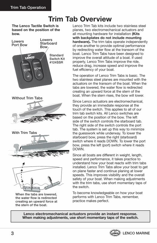
Lenco Trim Tab kits include two stainless steel planes, two electromechanical actuators and all mounting hardware for installation (Kits with backplates do not include mounting hardware). The trim tabs operate independently of one another to provide optimal performance by redirecting water flow at the transom of the boat. Lenco Trim Tabs have been designed to improve the overall attitude of a boat. If used properly, Lenco Trim Tabs improve the ride, reduce drag, increase speed and improve the fuel efficiency of your boat.The operation of Lenco Trim Tabs is basic. The two stainless steel planes are mounted with the actuators on the transom of the boat. When the tabs are lowered, the water flow is redirected creating an upward force at the stern of the boat. When the stern rises, the bow will lower.Since Lenco actuators are electromechanical, they provide an immediate response at the touch of the switch. This applies to all of our trim tab switch kits. All Lenco switches are based on the position of the bow. The left side of the switch controls the starboard tab. The right side of the switch controls the port tab. The system is set up this way to minimize the guesswork while underway. To lower the starboard bow, press the right (starboard) switch where it reads DOWN. To lower the port bow, press the left (port) switch where it reads DOWN. Since all boats are different in weight, length, speed and performance, it takes practice to understand how your boat reacts with trim tabs installed. Lenco Trim Tabs allow your boat to get on plane faster and continue planing at lower speeds. This improves visibility and the overall safety of your boat. When making adjustments with the trim tabs, use short momentary taps of the switch. To become knowledgeable on how your boat performs with Lenco Trim Tabs, remember, practice makes perfect.
The Lenco Tactile Switch is based on the position of the bow.
When the tabs are lowered, the water flow is redirected creating an upward force at the stern of the boat.
Without Trim Tabs
With Trim Tabs
Lenco electromechanical actuators provide an instant response.When making adjustments, use short momentary taps of the switch.
Standard Switch Kit#124SSR
Trim Tab Overview Trim Tab Operation

4Owner’s Manual
Trim Tab Operation
Head Sea — (Waves or current running directly against the course of a boat) Lower both tabs slightly by pressing BOW DOWN on both sides. This brings bow down while maintaining speed. This adjustment allows the hull of the boat to absorb the impact of the waves, resulting in a more efficient and smoother ride.
Following Sea — (Waves or current running with the course of a boat) Make sure the tabs are fully retracted by pressing BOW UP on both sides. This brings both tabs to a fully retracted position decreasing lift in the stern, allowing the bow to rise. If tabs are deployed, the bow may dig.
Windy Chop — To raise the windward side of the boat press BOW UP on that side. If this is not sufficient, press BOW DOWN on the leeward side of the boat. Do not over trim when attempting this. This allows the windward side of the boat to rise and minimizes spray.
Shallow Water/Hole Shot — Lower both tabs completely down by pressing BOW DOWN on both sides. This provides lift in the stern of the boat and keeps the bow down. As you throttle up and speed increases, raise tabs by pressing BOW UP on both sides.
Uneven Load — If one side of the boat is higher than the other while running, press BOW DOWN on the switch on that side. This lowers the tab on the listing side (low side) to bring the boat level.
Porpoising — (When the bow of the boat leaps clear out of the water after striking a wave.) To stop porpoising, press BOW DOWN on both sides of the switch. The tabs need only to be deployed slightly to correct this adverse situation.
• While the boat is underway, do not move one tab up or down significantly as this may cause listing.
• While at higher speeds, do not over trim. This causes the bow to lower quickly, resulting in a reduction of speed and may cause the boat to veer.
• When in following seas or when running an inlet, the tabs should be fully retracted. This allows for optimal performance.
• While operating trim tabs, use caution. Improper use of trim tabs may cause accidents and/or injury.
SAFETY
SPeCIAL CONDITIONS
HeAD SeA
FOLLOWING SeA
WINDy CHOP
SHALLOW WATeR HOLe SHOT
UNeVeN LOAD
PORPOISING

5 LENCO MARINEANGLE OF THE TAB
UPPER BRACKET CORRECT ORIENTATION
LOWER BRACKET INSTALLATION
UPPER BRACKET CORRECT ORIENTATION TRIM TAB INSTALLATION
5/8"gap(1.59 cm)
3/8"gap(.95 cm)
14"(35.56 cm)maximumtransomheight
needed
HULL LINE HULL LINE9" TAB(22.86 cm)
3/4"gap(1.9 cm)
1"gap(2.54 cm)
12" TAB(30.48 cm)
16" TAB(40.64 cm)
2" (or more)
2" (or more)
3/8"(.95 cm) up from hull
Edge of hinge must be 2" (5.08cm) from strake edge in either direction
1" to 4" in from chine
TRANSOM
Bolts enter from theunderside of tab
FIG.2
FIG.3
FIG.4
FIG.5
FIG.1
Trim Tab System Installation InstructionsWarning: The following instructions contain important safety information and should be followed carefully. Failure to do so may result in injury and will void warranty. Please read through the instructions in their entirety prior to beginning installation!
Trim Tab Installation Instructions
• Electric drill • Tape measure • 3/16" & 3/8" drill bits (.48 & .95 cm)• 7/16" (1.11 cm) wrench • 4' (1.22 m) level
• Straight edge • 2" (5.08 cm) hole saw• #2 & #3 Phillips screwdrivers• 3M 5200 adhesive caulking• Wire crimper / cutter
Fig. 1
TOOLS AND MATeRIALS LIST
Installation of trim tab blades 1. To begin, determine where the Lenco Trim
Tab Kit will be installed. Note: When laying out the desired tab location, hold the tab against the transom with the bottom of the hinge knuckle 3/8" (.95 cm) up from the bottom of the transom, approximately 1" to 4" (2.54 to 10.56 cm) in from the chine, and parallel with the hull.
Note: The reason the hinge knuckle is mounted 3/8" (.95 cm) from the bottom of the transom is to allow water to travel along the bottom of the boat and create lift when it is redirected in the tab area. Tabs are also mounted in this manner for protection while on a boat trailer or when being dry-stored.
When mounting the hinge to the hull make sure that the inside corner of the hinge knuckle is no closer than 2" (5.08 cm) to the left or right of any strake edge. The hinge may overlap a strake edge as long as any corner of the hinge knuckle is no closer than 2" (5.08 cm) to the left or right of the strake edge (see Fig.1). Transfer (trace) the hinge screw hole pattern onto the transom for drilling.
Note: All Performance Series tabs with single-tapered blades should be mounted with the tapered end facing toward the center of the boat. 2. Using the 3/16" (.48 cm) drill bit, drill
the previously marked hole locations to a depth of 1-1/4" (3.17 cm).
Note: When drilling out the screw hole pattern for the trim tab hinge you may drill through the transom. Hinge screws should be installed with 3M 5200 adhesive caulking which will seal the holes. All supplied screws and fasteners are stainless steel or brass. Do not use any other type of alloy.
Mount the trim tab hinge to the transom using provided #14 x 1-1/4" (3.17 cm) stainless steel sheet metal screws. We recommend using 3M 5200 adhesive caulking to bed the hinge and screws. DO NOT OVeRTIGHTeN.

6Owner’s Manual
Installation of Upper and Lower mounting brackets & actuators1. Loosely attach the upper mounting bracket
(bracket with four holes) to the top of the actuator using the 5/16-18" X 1-3/4" (4.45 cm) large hex head bolt and 5/16-18 hex nut provided. Attach the actuator to the lower mounting bracket using the 5/16-18" X 1-3/4" (4.45 cm) large hex head bolt and 5/16-18" hex (.79 cm) nut provided. Attach the lower mounting bracket to the tab with the bolts, washers, and nylon lock nuts (KIT4) provided (see Fig. 4).
2. In order to properly position the upper mounting bracket against the transom, you must lift the trim tab so that the trailing edge is approximately, 5/8" (1.59 cm) for a 9" trim tab and 3/4" (1.9 cm) for a 12" trim tab, above the straight edge when held to the hull (see Fig. 2.1 & 2.2). When the trim tab is at the appropriate level and the actuators are fully retracted, transfer (trace) the outer shape of the upper mounting bracket onto the transom. The upper mounting bracket should be marked where it lays naturally against the transom to prevent binding during functioning of trim tabs.
Note: Do not adjust the upper mounting bracket to the right or left, as this will cause binding. Allow the bracket to come to rest at its natural position.
Remove the upper mounting bracket from the actuator and align to the previously marked location to mark the upper mounting bracket screw hole locations and cable hole location. Using the 3/16" (.48 cm) drill bit, drill the three previously marked screw hole locations to a depth of 1-1/4" (3.17 cm).
Warning: With some installations, fuel, water tanks and/or other systems may prevent the actuator cable from entering the hull through the upper mounting bracket. Be sure to check inside the hull before drilling the 3/8" (.95 cm) cable hole. Note: When drilling out the screw hole pattern for the upper mounting bracket, you may drill through the transom. The screws should be installed with 3M 5200 adhesive caulking which will seal the holes when installed. All supplied screws and fasteners are stainless steel and brass. Do not use any other type of alloy.
(Continued on page 7)
Trim Tab Installation Instructions
5/8"(1.59 cm)
14"(35.56 cm)
max.height
needed for
actuator
3/8" (.95 cm)
9"(22.86 cm)
3/4" (1.9 cm)
12"(30.48 cm)
Standard MountFig. 2.1
3/4"(1.9 cm)
1"(2.54 cm)
12"(30.48 cm)
11"(27.94 cm)
max.height
needed for
actuator
13.5"(34.29 cm)
max.height
needed for
actuatorin 9"
(22.86 cmtab length)
3/8"(.95 cm)
16"(40.64 cm)
edge MountFig. 2.2
Fig. 3
ANGLE OF THE TAB
UPPER BRACKET CORRECT ORIENTATION
LOWER BRACKET INSTALLATION
UPPER BRACKET CORRECT ORIENTATION TRIM TAB INSTALLATION
5/8"gap(1.59 cm)
3/8"gap(.95 cm)
14"(35.56 cm)maximumtransomheight
needed
HULL LINE HULL LINE9" TAB(22.86 cm)
3/4"gap(1.9 cm)
1"gap(2.54 cm)
12" TAB(30.48 cm)
16" TAB(40.64 cm)
2" (or more)
2" (or more)
3/8"(.95 cm) up from hull
Edge of hinge must be 2" (5.08cm) from strake edge in either direction
1" to 4" in from chine
TRANSOM
Bolts enter from theunderside of tab
FIG.2
FIG.3
FIG.4
FIG.5
FIG.1
Fig. 4

7 LENCO MARINE
If all is clear, use the 3/8" (.95 cm) drill bit and drill the previously marked cable hole completely through the transom. Insert the actuator cable through the appropriate hole in the upper mounting bracket until the mount reaches the actuator. Insert the actuator cable through the gland seal until it reaches the rear of the upper mounting bracket.
Note: For appropriate orientation of upper mounting bracket and gland seal, (see Fig 3 on page 6).
If, however, you are prevented from drilling a hole through the transom at the bracket location, using the 3/8" (.95 cm) drill bit, simply drill a 3/8" (.95 cm) hole 4" to 5" (10.16 to 12.7 cm) above the waterline and insert the cable. Cover the hole and cable with a clamshell vent sealed with 3M 5200 for a waterproof and finished effect.Insert the actuator cable through the transom. With the actuator loosely supported, start the provided #14 x 1-1/4" (3.17 cm) stainless steel sheet metal screws through the upper mounting bracket holes and into the transom. MAKE SURE TO LEAVE THE SCREWS ONLY PARTIALLY INSTALLED. Insert the actuator clevis (mounting ear) into the upper mounting bracket and hold the actuator in the approximate installed position. Pass the actuator cable through the transom removing slack on the cable until it looks like the installation on Fig 2.1 on page 6. Finish installing the previously started #14 x 1-1/4" (3.17 cm) stainless steel sheet metal screws through the upper mounting bracket and into the transom. We recommend using 3M 5200 adhesive caulking to bed the upper mounting bracket and screws. DO NOT OVERTIGHTEN.
Attach and secure the actuator to the upper mounting bracket using the 5/16-18 X 1-3/4" (4.45 cm) large hex head bolt and 5/16-18 (.79 cm) hex nut provided. We recommend using 3M 5200 adhesive caulking to seal the cable hole on the inside of the transom. Attach connector ends to the actuator wire pins as instructed in Actuator Deutsch Connector Instructions insert card provided. If using actuator extension cables, this would be a good time to run them to the control box mounting area.
switch InstallationInstallation instructions for Standard (124SSR), Indicator (123SC), and Dual Ram Indicator (123DR) Digital Tactile Switches.1. At the helm, determine where the
tactile key pad will be installed, locate the template on page 22 and secure to helm. Cut a circular opening using a 2" (5.08 cm) hole saw (Hole must be 2"). Before cutting, make sure the area inside the helm is clear of wires and other equipment that could be damaged. Using the template on page 22, drill four 3/16" (.48 cm) holes through the helm.
2. Install the black control box (hardware not included) within 24" (60.96 cm) of the key pad hole. Make sure control box is mounted on a vertical surface with wires facing down toward the deck. Mounting the control box in the incorrect orientation will void the warranty.After mounting the control box, feed the key pad cable up thru the 2" hole and connect it to the backside of the key pad. Leave adequate slack in the cable connecting to the plug on the backside of the key pad. No slack or the tight bundling of the wires can cause damage to the key pad plug!
Trim Tab Installation Instructions
Installation Instructions continued from page 6.
Owner’s Manual 8
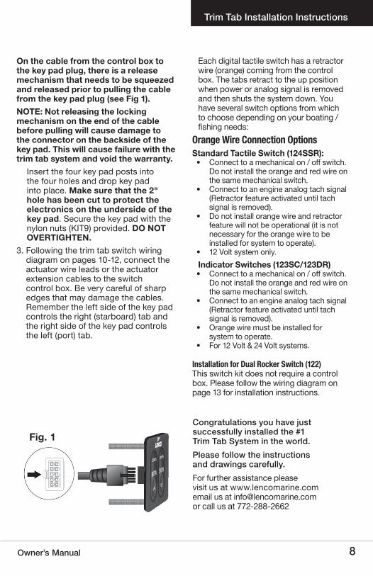
On the cable from the control box to the key pad plug, there is a release mechanism that needs to be squeezed and released prior to pulling the cable from the key pad plug (see Fig 1).NOTe: Not releasing the locking mechanism on the end of the cable before pulling will cause damage to the connector on the backside of the key pad. This will cause failure with the trim tab system and void the warranty.
Insert the four key pad posts into the four holes and drop key pad into place. Make sure that the 2" hole has been cut to protect the electronics on the underside of the key pad. Secure the key pad with the nylon nuts (KIT9) provided. DO NOT OVeRTIGHTeN.
3. Following the trim tab switch wiring diagram on pages 10-12, connect the actuator wire leads or the actuator extension cables to the switch control box. Be very careful of sharp edges that may damage the cables. Remember the left side of the key pad controls the right (starboard) tab and the right side of the key pad controls the left (port) tab.
Each digital tactile switch has a retractor wire (orange) coming from the control box. The tabs retract to the up position when power or analog signal is removed and then shuts the system down. You have several switch options from which to choose depending on your boating / fishing needs:
orange Wire Connection options Standard Tactile Switch (124SSR): • Connect to a mechanical on / off switch.
Do not install the orange and red wire on the same mechanical switch.
• Connect to an engine analog tach signal (Retractor feature activated until tach signal is removed).
• Do not install orange wire and retractor feature will not be operational (it is not necessary for the orange wire to be installed for system to operate).
• 12 Volt system only.Indicator Switches (123SC/123DR)• Connect to a mechanical on / off switch.
Do not install the orange and red wire on the same mechanical switch.
• Connect to an engine analog tach signal (Retractor feature activated until tach signal is removed).
• Orange wire must be installed for system to operate.
• For 12 Volt & 24 Volt systems.
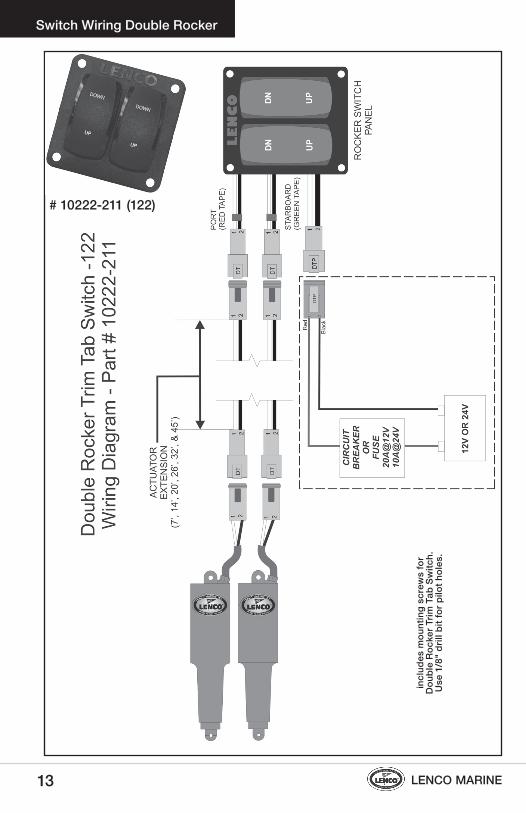
Installation for Dual rocker switch (122)This switch kit does not require a control box. Please follow the wiring diagram on page 13 for installation instructions.
Fig. 1
Trim Tab Installation Instructions
Congratulations you have just successfully installed the #1 Trim Tab System in the world. Please follow the instructions and drawings carefully. For further assistance please visit us at www.lencomarine.com email us at [email protected] or call us at 772-288-2662

9 LENCO MARINE
sWItCh oPeratIoNThe operation of all Lenco switches is based on the position of the bow. To lower the starboard bow, press the right (starboard) side of the switch where it reads Down. This lowers the port tab. To lower the port bow, press the left (port) side of the switch where it reads Down. This lowers the starboard tab.
Indicator Switch (123SC) with Self Check FeatureOn the Indicator switch, the L.E.D. lights on the sides of the display show how far that tab has moved. When the on/off switch is turned on at the helm or the engine’s tachometer circuit becomes active, the L.E.D. displays on the indicator switch light from top to bottom and immediately extinguish from bottom to top to indicate self test at power up. If there is a problem with an actuator connection the L.E.D. displays shows every other light red ”ON“ at the side
that has the problem (see Fig.1). After self test is complete (1 to 2 seconds) the L.E.D. displays show one up arrow on each side of the switch. This shows that both tabs are fully retracted. While operating the tabs, the L.E.D. displays indicate the position of the tabs by lighting up the further they are pressed down. As the switch is pressed up, the lights go out. When power is removed from the switch, the tabs retract from any position before powering down (See page 8 for more information).Dual Ram Indicator Switch (123DR) At start up the L.E.D. displays show one up arrow on each side of the switch. This shows that both tabs are functioning and are fully retracted. While operating the tabs, the L.E.D. displays indicate the position of the tabs by lighting up the further they are pressed down. As the switch is pressed up, the lights go out. When power is removed from the switch, the tabs retract from any position before powering down (See page 8 for more information).
Standard Switch #15069-001(124SSR)
To lower the starboard bow
To lower the port bow
Indicator Switch with Retractor #15070-001(123SC) #15071-001(123DR)
Switch Operation
Fig. 1

10Owner’s Manual
Switch Wiring #15069-001 (124SSR)

11 LENCO MARINE
Switch Wiring #15070-001 (123SC)

12Owner’s Manual
Switch Wiring #15071-001 (123DR)
13 LENCO MARINE
Switch Wiring Double Rocker
# 10222-211 (122)
incl
udes
mou
ntin
g sc
rew
s fo
r D
oubl
e R
ocke
r Trim
Tab
Sw
itch.
U
se 1
/8"
drill
bit
for p
ilot h
oles
.

14Owner’s Manual
RetroFit Kit for Bennett Trim Tabs Installation Instructions
retroFit kit for bennett trim tabs Installation Instructions
Pre-Installation Instructions 1) Disconnect the Bennett hydraulic pump
unit (HPU) from the Bennett wiring harness and drain as much of the hydraulic fluid as possible into a container for proper disposal later. Remember that automatic transmission fluid (ATF) is to be disposed of only at an approved collection site in your area; do not discard in the regular trash. Discard hydraulic pump unit (HPU). Leave Bennett wiring harness in place.
2) Remove and discard the Bennett trim tab cylinders from the boat transom and remove the hydraulic line at the connection. It helps to have several rags handy to soak up the oil. Remove and discard old hydraulic lines.
3) Disconnect the Bennett cylinder from the trim tab plane by tapping out the small black pin at the base of the cylinder where it attaches to the plane. You will first have to remove one screw from the lower mounting bracket as this holds the pin in place. Do not remove the lower mounting bracket, as you will need it later.
Installation Instructions1) Insert the actuator cable through the
appropriate hole in the upper mounting bracket (supplied with the kit) until it reaches the actuator. Insert the actuator cable through the gland seal until it reaches the upper mounting bracket.
Note: For appropriate orientation of upper mounting bracket and gland seal, (see Fig 1).
You will need to clean the mounting surfaces on the transom with a cleaning solvent such as mineral spirits or alcohol to remove all oils and dirt before final mounting.Insert the actuator cable through the transom. With the actuator loosely supported, bed the upper mounting bracket and screws with 3M 5200 adhesive caulking. Start the provided #14 x 1-1/4" (3.17 cm) stainless steel sheet metal screws through the upper mounting bracket and into the transom. MAKE SURE TO LEAVE THE SCREWS ONLY PARTIALLY INSTALLED.Insert the actuator clevis (mounting ear) into the upper mounting bracket and hold in the approximate installed location. Pass the actuator cable through the transom removing slack on the cable until it looks like the installation on Fig 2.1 on page 6. Remove the actuator from the upper mounting bracket and finish installing the previously started #14 x 1-1/4" (3.17 cm) stainless steel sheet metal screws through the upper mounting bracket and into the transom.
Lenco Marine’s RetroFit Kit is designed as a direct replacement for the Bennett hydraulic power unit (HPU) on systems using Bennett's 4-ring standard trim tab actuators. Note: Bennett Joystick Control can not be retrofitted to the Lenco Actuators.These instructions should be followed completely. See page 5 for complete Tools and Materials List. If you experience any problems not covered, please call the Lenco Marine Customer Service line at 772-288-2662.Make sure the power is removed from the Bennett Trim Tab System before installation.
Fig. 1
(Continued on page 15)

LENCO MARINE
Optional Switches
15
Lenco wire feeds through existing oil line hole in transom
Lenco upper mounting bracket fits existing Bennett mounting holes
Existing Bennett lower actuator bracket
Existing Bennett trim tab plane and hinge
We recommend using 3M 5200 adhesive caulking to bed the upper mounting bracket and screws.DO NOT OVeRTIGHTeN.Attach the actuator to the upper mounting bracket using the 1-1/2" Delrin Pin provided.
2) You are now ready to attach the Lenco Actuator to the blade. First insert the 1-1/4" Delrin Pin part way through the hole in the Bennett lower mounting bracket and insert through one of the four black washers provided in the kit. Place the actuator into the bracket and tap the pin through. Continue through the second washer and other side of the bracket. Replace the bracket screw removed in step 3 on page 14. This will lock the pin in place and prevent it from falling out.
3) Now you will need to hook up the Lenco Actuator wires inside the bilge/rigging area. First cut the wire connector from
the Bennett wire harness where the pump used to be. Strip the four harness wires and connect to the four Lenco wires using the heat shrink butt splices provided in the kit. Make sure to use the proper crimping tool and then heat all connections for a tight waterproof seal. Tie-wrap or secure in some fashion to a dry location to help prevent the connectors from getting too wet.
4) Switch Installation: Remove Bennett switch and install new Lenco Switch. Follow the switch wiring diagram on page 16. See page 7-8 for complete switch kit installation instructions.
Please follow the instructions and drawings carefully. For further assistance please visit our website at www.lencomarine.com, email us at [email protected], or call us at 772-288-2662
RetroFit Kit for Bennett Trim Tabs Installation Instructions
Lenco washers(One on each side of actuator)

16Owner’s Manual
RetroFit Kit for Bennett Trim Tabs Wiring Diagram

17 LENCO MARINE
Due to the many different variables involved with the numerous applications for Lenco hatch lifts, installation is never the same. Here are some general guidelines that can be of assistance:
• The actuator is most powerful when it is installed vertically at 90 degrees.
• Lifting capabilities decrease (due to the fact that the force pounds increase) the closer the upper or lower mount is located to the hinge.
• The further from a vertical position the less lifting capability. When retracted, Do Not position hatch lift at an angle less than 45 degrees.
• Dual hatch lift systems are recommended for hatches over 500 pounds (226.79 kg) of force.
• Lenco hatch lifts are designed around a ball screw that spins freely when hatch is fully open or closed.
• The hatch lift must be allowed to free spin at both ends of its stroke or it will continue to push or pull against any resistance potentially damaging the hatch lift or the hatch itself.
• Failure to make accurate measurements could cause damage to hatch lift or the hatch itself.
• Lenco hatch lifts are waterproof and will not drift. • Lenco hatch lifts are offered in both 12 and 24 volts.
Hatch Lifts — Installation/Operation
Lenco hatch Lift Installation/operation
OPeRATIONThe function of the Lenco Hatch Lift System is simple. Since the hatch lift is based around a ball screw it is able to push a heavy load and remain at a constant position. To raise a load, extend the hatch lift by pressing on the upper part of the switch. To lower a load, retract the hatch lift by pressing the lower part of the switch.In case of power failure, Lenco hatch lifts are supplied with two clevis pins at the mounting brackets. To pull this pin out while the hatch is closed, you can: A) Rig a cable to pin and rig to a point outside of the hatch. B) Install an inspection plate where the pin will be accessible. C) Install Lenco's hatch lift slide bracket (Part # 70381-001). This will allow you to pull the hatch open 4" (10.16 cm) in order to reach and pull pin.
Raise Hatch
Lower Hatch
Wiring Single Rocker Switch #15096-001
PowerGround
Single Rocker Switch for twin hatch lift application also available. See page 18 for part #.
Hatch lift
S = Short. All part numbers ending in S have the same stroke but in a 4" (10.16 cm) shorter length.
12V Part L. O. A. Approx. L. O. A. Number Retracted Stroke Extended20760-001 15" 4" 19"20764-001 20" 8" 28"20766-001 24" 8" 32"20768-001 24" 12" 36"20770-001 29" 12" 41"20774-001 29" 16" 45"20776-001 33" 16" 49"20778-001 33" 20" 53"20780-001 37" 20" 57"20782-001 37" 24" 61"20784-001 41" 24" 65"

18Owner’s Manual
1 Hatch Lift #’s 20760-001, 20764-001, 20766-001, (electromechanical actuator) 20768-001, 20770-001, 20774-001, 20776-001, 20778-001, 20780-001, 20782-001, 20784-0012 Upper Mounting brackets #50015-001 (118)3 Lower Mounting bracket #50014-001 (119)4 Clevis pins #60101-001 (121SS) 5 Single rocker switch for single HL application #15096-001 (optional)6 Single rocker switch for twin HL application #15098-001 (optional)7 Shim - 7˚ #50015-002 (118S) (optional)8 Slide bracket #70381-001 (HLSB) (optional)
SYSTEM PARTS
1. Follow the chart above to figure out load on the hatch lift. Maximum load is 500 lbs. (226.79 kg)Y = Total length of hatchX = Length from the hinge to the hatch
lift mounting pointW = Weight of the hatch to be lifted
2. Determine the angle of the hatch lift mount. Do not exceed 45 degrees from center.
3. Mount the hatch lift on the desired location as per the above instructions. Important: It may be necessary to
shim the upper or lower mounting bracket up or down so the hatch does not bind when fully closed. The hatch lift does not stop pulling until it has reached its fully closed position. If the hatch fully closes before the hatch lift is fully retracted, it will cause damage to the lift or the mounting hardware. Shim the hatch lift with stainless washers for small amounts of length. Use Lenco shim part #50015-002 for lengths greater then 1/8" (3 mm).
4. Wire to switch according to the hatch lift wiring diagram on page 17.
Lenco hatch Lift mounting
Hatch Lifts — Mounting/Parts
45MAX
45MAX
Hatchlift
Y Length IN/CM
X Length IN/CM
W LBS/KG
YxW÷X=Force

19 LENCO MARINE
Trim Tab Maintenance Tips
trim tab maintenance tipsCLeANING The attractive surface appearance of stainless steel cannot be regarded as completely maintenance-free. Our 304 Series Stainless Steel may in fact stain, discolor, or accumulate a layer of surface contamination (dirt and grime) during the normal course of the life cycle. Minute particles of dust and rust may adhere to the stainless steel during shipping, installation, or storage at OEM or retail locations. Also, please remember that some types of stainless steel fasteners tend to “bleed” over the tabs and onto the boat. To achieve maximum corrosion resistance, the surface of the stainless steel must be kept clean and free of all of these contaminants.
• Lenco recommends an acid and water solution to clean the tabs.• MaryKate’s On & Off Product is a good choice. Biodegradable, but
please follow the manufacturer’s instructions before applying.
PAINTING yOUR LeNCO SS TRIM TABS and ACTUATORS Painting your tabs and actuators with marine antifouling paint will discourage marine algae or growth from adhering to these surfaces.
• Please follow the instructions supplied by your choice of marine paint suppliers.
• When applying paint to the actuators, be sure that they are in the fully retracted position. Do not paint the stainless steel ram above the area that is exposed when retracted.
• Do not paint under the anode or the anode itself.
SACRIFICIAL ANODeS FOR yOUR LeNCO SS TRIM TABS Be aware that stray currents in your marina or in a visiting marina can cause damage to your trim tab blades if not protected by sacrificial anodes.
• The addition of anodes on each tab will deter electrolysis.• Do not paint under the anode or the anode itself.• Check Anode condition frequently. Replace when necessary.
eLeCTROLySIS IS NOT A MANUFACTURING DeFeCT AND IS NOT WARRANTABLe.
VISUAL INSPeCTION OF SySTeM
• Periodically inspect all wires, mounting brackets, and hardware for damage.
• Make sure all mounting brackets and hardware are secure and working properly.
• Periodically test system for smooth operation.

20Owner’s Manual
2010 Warranty Policy
2010 Warranty Policy Lenco Marine Incorporated warrants its new products to be free from defects in material and workmanship for the following periods:
• Trim Tab Systems: 3 years from the original date of purchase.• Retro Fit Kits: 3 years from the original date of purchase.• electric Hatch-Lift: 2 years from the original date of purchase.• electrical Switches: 3 years from the original date of purchase.• electric Drive Units: 3 years from the original date of purchase.• electric Propulsion Controllers: 1 year from original date of purchase.
Lenco Marine Inc will, at our sole discretion, repair or replace any product that has proven to meet warranty eligibility in accordance with this policy. Any replacement or refurbished product will be warranted in accordance with this policy for the unexpired balance of the warranty period on the original product. Policies regarding freight and other charges are as follows:
• Freight charges associated with warranty products required to be returned to Lenco Marine Inc will be the responsibility of the customer.
• Charges associated with warranty product that is damaged during its return to Lenco Marine due to improper packaging will be the responsibility of the customer.
• Once the product is proven to meet warranty eligibility, Lenco Marine will be responsible for standard return freight within the continental United States.
• All freight charges from warranty claims submitted from outside the continental United States are the sole responsibility of the customer.
• Lenco Marine is not responsible for charges related to the removal of such product including haul out, labor or any other miscellaneous charge(s).
• This warranty is not transferable.
This policy does not apply to product that has been: • Damaged due to improper installation or operation.• Damaged due to abuse or neglect.• Modified from its original state without the express written consent from
Lenco Marine.• Used on a vessel where the engine horsepower exceeds the
recommendation of the boat manufacturer.• Damage due to Electrolysis.
The warranty period for products used commercially or in any rental or other income producing activity will be 90 days from the original date of purchase.
The foregoing is in lieu of any and all other warranties, expressed or implied, including any warranty of merchantability or fitness for a particular purpose. There are no other warranties which extend beyond that set forth above. Lenco Marine Inc., reserves the right to void any warranty claim if the part is opened or repair was attempted, without the express written consent from Lenco Marine Inc.

21 LENCO MARINE
Glossary
GLOSSARy
Bow Front part of a boat
Chine Portion of the hull where the bottom and sides intersect
Following Sea Waves of current running with the course of a boat
Head Sea Waves or current running directly against the course of a boat
Helm Area of a boat where operational controls are located
Hull The main body of a boat
Porpoising When the bow of a boat leaps clear out of the water after striking a wave
Port The left side of a boat looking forward
Starboard The right side of a boat when looking forward
Stern Rear part of a boat
Strake edge Points on the bottom of a hull (see Fig. 1 on page 5)
Trailing edge The furthest edge from the hinge on a trim tab
Transom The rear section of the hull connecting the two sides

22Owner’s Manual
124ssr / 123sC / 123Dr tactile switch templateRemove the template from the owner’s manual by cutting around the dashed rectangular perimeter line. Align the 3/16" (.48 cm) drill bit with each of the four black circles and drill straight down through the helm, providing
clearance for the mounting hardware provided with the switch.Align the centering bit of a 2" (5.08 cm) hole saw with the cross hairs in the center of the 2" (5.08 cm) dashed circular perimeter and drill straight down through the helm, providing additional clearance for switch and electrical connection.
2" (5.08 cm) hole for Switch Key Pads
Tactile Switch ConnectionMount control box within 24" (60.96 cm) of keypad. Control box wire harness is 30" (76.2 cm) in length
Switch Template
122 Double Rocker Switch TemplateRemove the template from the owner’s manual by cutting around the dashed rectangular perimeter line. Align the centering bit of a 2.25" (5.715 cm) hole saw with the cross hairs in the center of the 2.25" (5.715 cm) dashed circular perimeter and drill straight down through the helm, providing additional clearance for switch and electrical connection. Before drilling the four switch mounting holes, drill a small pilot hole using a 1/8" (.3175 cm) diameter drill bit. Make sure pilot holes are straight.

Lenco Marine Inc., 4700 Municipal Court • Stuart, Florida 34997772-288-2662 • 772-288-2566 fax • www.lencomarine.com
DoN’t WorrY…
we’ve got your back.
4.10.13