OWNER’S MANUAL QUESTIONNAIRE - Monaco Coach · OWNER’S MANUAL QUESTIONNAIRE ... Your motorhome...
327
Transcript of OWNER’S MANUAL QUESTIONNAIRE - Monaco Coach · OWNER’S MANUAL QUESTIONNAIRE ... Your motorhome...


OWNER’S MANUAL QUESTIONNAIRE
Your suggestions are very important to us and we are continually striving toimprove the quality of our manuals. After becoming familiar with your newrecreational vehicle and the accompanying manual, please take the time toanswer the following questions. When you are finished please return it, postagepaid, to our Technical Publications Department. Feel free to attach an additionalpage if you desire.
1. Is this your first recreational vehicle? YES / NO
2. Was the overall appearance and lay-out of this manual what you expect-ed to see in your new recreational vehicle?________________________________________________________________________________________________________________________________________________________________________________________________________________________________________________________________________________________________________________________________
3. Was the information within this manual helpful in acquainting you withyour new recreational vehicle? If not please address any area(s) we need toexpand or improve on. ________________________________________________________________________________________________________________________________________________________________________________________________________________________________________________________________________________________________________________________________
4. Were the operating instructions clearly written, and were you able to follow the steps without any difficulty?________________________________________________________________________________________________________________________________________________________________________________________________________________________________________________________________________________________________________________________________
5. Is there any additional information you would like to see incorporatedwithin the owner’s manual?________________________________________________________________________________________________________________________________________________________________________________________________________________________________________________________________________________________________________________________________NAME: ___________________________ PHONE: (_____)_____________ADDRESS: ____________________________________________________
SIGNATURE SERIES 2001
CUT ALONGDOTTED LINE

FOLD
CUT ALONGDOTTED LINE
FOLD

SIGNATURE SECTIONS
SIGNS--------------------------------------------------------------------------------------------------------------------------------------------------------------------------------------------------------------------------------------------------------------------------------------------------------------------
This s ign indicates a NOTE.
This s ign indicates INSPECTION is requi red .
This s ign indicates a WARNING or a CAUTION with addi t ional in format ion at tached.
This s ign indicates ASSEMBLY/ INSTALLATION orDISASSEMBLY/REMOVAL is necessary.
This s ign indicates the speci f ied par t requi resOIL/LUBRICATION.
This s ign indicates a re ference to the WarrantyINFORMATION FILE located wi th in the gray box ins ide your motorhome.
Product information and specifications are shown herein as of the time of printing. Monaco reserves the right to change product
specifications, designs and standard equipment without notice and without incurring obligation.

1
SIGNATUREINTRODUCTION • 8
CUSTOMER RELATIONS • 8REPORTING SAFETY DEFECTS • 9
TAKING DELIVERY • 9Monaco Responsibilities • 9
Dealer Responsibilities • 9 Customer Responsibilities • 10
WARRANTY INFORMATION FILE • 10SERVICE SUGGESTIONS • 11
OWNER’S RECORD - SERIAL NUMBERS • 12OWNER’S RECORD - PERSONAL PROPERTY • 13
OWNER’S RECORD - INSURANCE • 14LIMITED WARRANTY • 15
Limitations of Implied Warranties • 15What the Warranty Covers • 16
What We Will Do to Correct Problems • 16How to Get Service • 16
What the Warranty Does Not Cover • 17Events Discharging Warrantor from Obligation Under Warranty • 17
Disclaimer of Consequential & Incidental Damages • 17Legal Remedies • 18
LIMITED WARRANTY - ROADMASTER CHASSIS • 18Limitations of Implied Warranties • 18
What the Warranty Covers • 19What We Will Do to Correct Problems • 19
How to Get Service • 19What the Warranty Does Not Cover • 20
Events Discharging Warrantor from Obligation Under Warranty • 20Disclaimer of Consequential & Incidental Damages • 20
Legal Remedies • 21VENDOR LIST • 22
SECTION 1WARRANTY & INFORMATION


Information & Warranty------------------------------------------------------------------------------------------------------------------------------------------------------------------------------------------------------------------------------------------------------------------------------------------------------------------
S I G N AT U R E S E R I E S 1 • 8
This chapter contains warranty information and knowledge for the operationand care of the motorhome. Not all information may be applicable to your modelof motorhome. More detailed information with CAUTION or WARNING instruc-tions, other than what is found in this chapter, can be found in the manufacturer’sowner manuals located in the owner information box.
In time you will develop a knack for spotting wonderful little roadside locations by turning off the main highway and exploring. There are many modernrecreational vehicle parks (including state, county and federal parks) with goodfacilities where you can obtain hook-ups for electrical, water and sewage connec-tions. Directories are published which describe these parks and the availability ofservices and hook-ups. On overnight or weekend trips, chances are you will prob-ably not fill up the sewage holding tanks, deplete the water or LP-Gas supply, orrun down the batteries which supply the living area with 12 Volt DC current. Onlonger trips, when you have stayed where sewer connections and utility hook-upswere not available, it will be necessary to stop occasionally to empty the holdingtanks and replenish the water and LP-Gas supply.
Many gas stations have installed sanitary dumping stations. Publications areavailable which list these dumping stations. When stopped for the night theMonaco motorhome is built to be safely parked in any spot that is relatively leveland where the ground is firm. Try to pick as level a parking spot as possible. Yourfacilities are with you and the motorhome is fully self-contained.
The safety alert symbols of CAUTION or WARNING are “Personal SafetyInstructions.” It is important to thoroughly read and understand these safetyinstructions where the symbols are displayed throughout the manual. Failure tocomply with specific instructions may result in personal injury or death. Manyinstructions are required by National Safety Associations.
------------------------------------------------------------------------------------------------------------------------------------------------------------------------------------------------------------------------------------------------------------------------------------------------------------------
Only by ensuring your confidence and satisfaction with our products andservices can we have continued success as a manufacturer of motorhomes. Webelieve a good relationship with our customers is just as important as improvingthe technical excellence of our products. Your authorized dealer is pleased tohelp you with instructions about your motorhome and to offer service whenyou need it. If problems remain after you have consulted your dealer you areinvited to contact our Consumer Affairs Department. Please have all pertinentinformation (serial numbers, model number, etc.) when calling. We will workwith the dealer and see that every attempt to resolve the matter is made.
Customer Service DepartmentMonaco Coach Corporation
91320 Coburg Industrial WayCoburg, Oregon 97408
877-466-6226
INTRODUCTION
CUSTOMERRELATIONS

If you believe that your motorhome has a defect which could cause a crashor could cause injury or death, you should immediately inform the NationalHighway Traffic Safety Administration (NHTSA) in addition to notifyingMonaco. If NHTSA receives similar complaints, it may open an investigation,and if it finds that a safety defect exists in a group of motorhomes, it may ordera recall or remedy campaign. However, NHTSA cannot become involved inindividual problems between you, your dealer or Monaco. To contact NHTSAyou may either call the Auto Safety Hot line toll-free at 1-800-424-9393 (or 1-202-366-0123 in Washington DC area) or write to:
NHTSA400 Seventh Street
US Department of TransportationWashington, DC 20590
---------------------------------------------------------------------------------------------------------------------------------------------------------------------------------------------------------------------------------------------------------------------------------------------------------------------
Your motorhome has been manufactured to the highest quality and standardsby factory trained personnel. Quality inspections are performed throughout themanufacturing process of your motorhome. Your motorhome has been carefullyand almost completely hand assembled in our factory. Prior to the motorhomearriving at the dealership, all systems have been carefully tested and inspectedto ensure optimum performance. The necessary forms and required manualshave been placed in the motorhome at the time of shipment to the dealership.
---------------------------------------------------------------------------------------------------------------------------------------------------------------------------------------------------------------------------------
The dealer must perform additional pre-delivery inspections and systemchecks, assist in the customer’s understanding of the Limited Warranty andassist in completing any necessary forms. They must do a customer orientationto the motorhome, its systems, components and their operation.
The dealer should also ensure the customer receives a complete Owner’sPacket with warranty cards and registrations for the motorhome and for sepa-rately warranted products, including detailed operating and maintenance instructions. The dealer is responsible for performing a review of the LimitedWarranty provisions with the customer, while stressing the importance of mailing warranty cards and registrations to the manufacturers within the pre-scribed time limit to avoid loss of warranty coverage. They must assist the customer in completing these forms and locating serial numbers. They shouldrequest that the customer reads all warranty information when possible andexplain any provision not clearly understood.
The dealer should instruct the customer on how to obtain local and out-of-town service on the motorhome and its various individual warrantedcomponents, whether the service is warrantable or out of warranty.
Information & Warranty---------------------------------------------------------------------------------------------------------------------------------------------------------------------------------------------------------------------------------------------------------------------------------------------------------------------
1 • 9 S I G N AT U R E S E R I E S
REPORTINGSAFETY DEFECTS
TAKING DELIVERYMonacoResponsibilities
DealerResponsibilities

Information & Warranty------------------------------------------------------------------------------------------------------------------------------------------------------------------------------------------------------------------------------------------------------------------------------------------------------------------
S I G N AT U R E S E R I E S 1 • 1 0
As a new motorhome owner you are responsible for regular and propermaintenance. This will help you prevent conditions arising from neglect thatare not covered by your Monaco Limited Warranty. Maintenance servicesshould be performed in accordance with this Owner’s Manual, and any otherapplicable manuals. As the owner, it is your responsibility and obligation toreturn the motorhome to an authorized dealer for repairs and service (SeeLimited Warranty). Since the authorized dealer where you purchased your newmotorhome is responsible for its proper servicing before delivery, and has aninterest in your continued satisfaction, we recommend that Inspection,Warranty and Maintenance Services be performed by the dealership. We suggest that you take your new motorhome on a weekend shakedown before leaving on an extended trip.
-------------------------------------------------------------------------------------------------------------------------------------------------------------------------------------------------------------------------------------------------------------------------------------------------------------------
In addition to this Owner’s Manual you will find a Warranty InformationFile in your unit. This file contains valuable documents about your motorhomesystems and equipment. Many of the component manufacturer’s warranty registration cards can be found in the box. They will need to be filled out andmailed. Be sure you read and understand all the information in this file to helpyou safely operate, maintain and troubleshoot those items.
MONACO COACH CORPORATION FINISHBecause no two trees look alike, authentic woods vary in color
and character markings such as streaks, knots and grain patterns.Since the stains may attach differently to these grain patterns,some natural light and dark areas may result. The beauty lies
in these natural variations of color and grain that giveeach cabinet its own individual charm.
The beauty of these products is protected with a furniture-qualityexterior finish. After a period of time, there may be minimal
changes in the finish color as it ages in its surrounding conditions.This is an inherent characteristic of this particular finish, and the
natural aging process adds to the unique appearance of the cabinetry.Due to the minor differences in tone, it may not be possible to
match the finish color of existing cabinets exactly when replacingdoors or adding additional cabinets at a later date.
Monaco Coach Corporation
The foregoing is not a warning. See Monaco Coach Corporation’s Limited Warranty or callMonaco Coach Corporation at (877) 466-6226 for warranty information and limitations.
Customer’sResponsibilities
WARRANTYINFORMATION
FILE

Know when to take your motorhome in for service. Give some thought tothe appointment time. There are several things to consider when selecting atime for service. Location of the service center and the time of year can be amajor issue. Monday and Friday are busy days for most dealers. Therefore, itmakes sense to make a mid-week appointment whenever possible. Ask yourdealer if additional time is needed for check in and completion of paperwork.
---------------------------------------------------------------------------------------------------------------------------------------------------------------------------------------------------------------------------------
If you’re having warranty work done, be sure to have your warranty registra-tion papers with you. All work to be performed may not be covered by the war-ranty; be sure to discuss additional charges with the service manager. Keep amaintenance log of your motorhome service history. This can often provide aclue to the current problem.
---------------------------------------------------------------------------------------------------------------------------------------------------------------------------------------------------------------------------------
Make a written list of specific repairs needed. It is important the servicemanager be aware of all previous work which has been done on yourmotorhome. For example: if the motorhome has been repaired due to an acci-dent. While this may not seem important, it could have a significant effect onthe dealer’s diagnosis of a problem.
---------------------------------------------------------------------------------------------------------------------------------------------------------------------------------------------------------------------------------
Don’t leave a list of 20 items to be serviced and expect to have yourmotorhome back by five o’clock. If you list a number of items, and you musthave your motorhome back by the end of the day, discuss the situation with theservice manager and list your items in order of priority. Some items may not beable to be repaired due to work loads or parts availability. Expect to make a sec-ond appointment for work not completed or for the long drawn out repair item.
--------------------------------------------------------------------------------------------------------------------------------------------------------------------------------------------------------------------------------
Please don’t be offended when you are told you can not watch the workbeing done. Many service area insurance requirements forbid the admission ofcustomers into the service work area.
--------------------------------------------------------------------------------------------------------------------------------------------------------------------------------------------------------------------------------
Check out the service or repair job when you pick up your motorhome andnotify the service manager of any dissatisfaction. If circumstances preventreturning for immediate corrective work, make an appointment as soon as possible.
Information & Warranty---------------------------------------------------------------------------------------------------------------------------------------------------------------------------------------------------------------------------------------------------------------------------------------------------------------------
1 • 1 1 S I G N AT U R E S E R I E S
SERVICESUGGESTIONS
Prepare for theAppointment
Prepare a List
Be Reasonable With Your Requests
No Looking Over the Technicians Shoulder
Inspect the WorkProperly

Information & Warranty------------------------------------------------------------------------------------------------------------------------------------------------------------------------------------------------------------------------------------------------------------------------------------------------------------------
S I G N AT U R E S E R I E S 1 • 1 2
FOR YOUR OWN REFERENCE
OWNER’S RECORD - SERIAL NUMBERS
Refer to the Manufacturer’s individual Owner’s Manuals for serial number locations thatare not listed below.
Motorhome Serial Number ______________________________________________________
Motorhome Federal Vehicle Identification Number (VIN) ______________________________
Door Key Number ____________________________________________________________
Range Model & Serial Number __________________________________________________(Located under top burner plate)
Microwave Model & Serial Number ______________________________________________(Located behind door on case)
Refrigerator Model & Serial Number ______________________________________________(Located inside refrigerator compartment)
Generator Model & Serial
Number_______________________________________________________________________(Located in outside compartment on generator)
Roof Air Conditioner Model & Serial Number_______________________________________(Located under top cover on air conditioner)
FORYOUROWNREFERENCE

Information & Warranty---------------------------------------------------------------------------------------------------------------------------------------------------------------------------------------------------------------------------------------------------------------------------------------------------------------------
1 • 1 3 S I G N AT U R E S E R I E S
for your own referenceOWNER’S RECORD - PERSONAL PROPERTY
Item Serial Number Value
______________________________________________________________________________________________________________________________________________________________________________________________________________________________________________________________________________________________________________________________________________________________________________________________
_____________________________________________________________________________________________________________________________________________________________________________________________________________________________________________________________________________________________________________________________________________________________________________________________
_____________________________________________________________________________________________________________________________________________________________________________________________________________________________________________________________________________________________________________________________________________________________________________________________
_____________________________________________________________________________________________________________________________________________________________________________________________________________________________________________________________________________________________________________________________________________________________________________________________
_____________________________________________________________________________________________________________________________________________________________________________________________________________________________________________________________________________________________________________________________________________________________________________________________
_____________________________________________________________________________________________________________________________________________________________________________________________________________________________________________________________________________________________________________________________________________________________________________________________
_____________________________________________________________________________________________________________________________________________________________________________________________________________________________________________________________________________________________________________________________________________________________________________________________
_____________________________________________________________________________________________________________________________________________________________________________________________________________________________________________________________________________________________________________________________________________________________________________________________
_____________________________________________________________________________________________________________________________________________________________________________________________________________________________________________________________________________________________________________________________________________________________________________________________
_____________________________________________________________________________________________________________________________________________________________________________________________________________________________________________________________________________________________________________________________________________________________________________________________
_____________________________________________________________________________________________________________________________________________________________________________________________________________________________________________________________________________________________________________________________________________________________________________________________
_____________________________________________________________________________________________________________________________________________________________________________________________________________________________________________________________________________________________________________________________________________________________________________________________
_____________________________________________________________________________________________________________________________________________________________________________________________________________________________________________________________________________________________________________________________________________________________________________________________
_____________________________________________________________________________________________________________________________________________________________________________________________________________________________________________________________________________________________________________________________________________________________________________________________
_____________________________________________________________________________________________________________________________________________________________________________________________________________________________________________________________________________________________________________________________________________________________________________________________
_____________________________________________________________________________________________________________________________________________________________________________________________________________________________________________________________________________________________________________________________________________________________________________________________
_____________________________________________________________________________________________________________________________________________________________________________________________________________________________________________________________________________________________________________________________________________________________________________________________
_____________________________________________________________________________________________________________________________________________________________________________________________________________________________________________________________________________________________________________________________________________________________________________________________
FORYOUROWNREFERENCE

Information & Warranty------------------------------------------------------------------------------------------------------------------------------------------------------------------------------------------------------------------------------------------------------------------------------------------------------------------
S I G N AT U R E S E R I E S 1 • 1 4
OWNER’S RECORD - INSURANCE
Company: _________________________________________________________________________________________________________________________________________________________________________________________________________________________________________________________________________________________________________________________________
_____________________________________________________________________________________________________________________________________________________________________________________________________________________________________________________________________________________________________________________________________________________________________________________________
Policy #:___________________________________________________________________________________________________________________________________________________________________________________________________________________________________________________________________________________________________________________________________________
_____________________________________________________________________________________________________________________________________________________________________________________________________________________________________________________________________________________________________________________________________________________________________________________________
Agent’s Name & Address:___________________________________________________________________________________________________________________________________________________________________________________________________________________________________
_____________________________________________________________________________________________________________________________________________________________________________________________________________________________________________________________________________________________________________________________________________________________________________________________
Business Phone #:_______________________________________________________________________________________________________________________________________________________________________________________________________________________________________________________________________________
_____________________________________________________________________________________________________________________________________________________________________________________________________________________________________________________________________________________________________________________________________________________________________________________________
Emergency Phone #:_________________________________________________________________________________________________________________________________________________________________________________________________________________________________________________________________
_____________________________________________________________________________________________________________________________________________________________________________________________________________________________________________________________________________________________________________________________________________________________________________________________
Renewal Date(s):_________________________________________________________________________________________________________________________________________________________________________________________________________________________________________________________________________________________
_____________________________________________________________________________________________________________________________________________________________________________________________________________________________________________________________________________________________________________________________________________________________________________________________
Notes: _______________________________________________________________________________________________________________________________________________________________________________________________________________________________________________________________________________________________________________________________________________________
_____________________________________________________________________________________________________________________________________________________________________________________________________________________________________________________________________________________________________________________________________________________________________________________________
_____________________________________________________________________________________________________________________________________________________________________________________________________________________________________________________________________________________________________________________________________________________________________________________________
_____________________________________________________________________________________________________________________________________________________________________________________________________________________________________________________________________________________________________________________________________________________________________________________________
_____________________________________________________________________________________________________________________________________________________________________________________________________________________________________________________________________________________________________________________________________________________________________________________________
_____________________________________________________________________________________________________________________________________________________________________________________________________________________________________________________________________________________________________________________________________________________________________________________________
FORYOUROWNREFERENCE

MONACO COACH CORPORATION LIMITED WARRANTY
What the Period of Coverage Is:If you use your Monaco motorhome only for recreational travel and family
camping purposes, the Limited Warranty provided by Monaco CoachCorporation ("Warrantor") covers your new motorhome when sold by anauthorized dealer, for twelve (12) months from the original retail purchase dateor the first 24,000 miles of use, whichever occurs first. However, the LimitedWarranty provided by Warrantor covers the steel or aluminum frame structureof the sidewalls (excluding slide-outs), roof, and rear and front walls for sixty(60) months from the original retail purchase date or the first 50,000 miles ofuse, whichever comes first.
If you use your motorhome for any rental or commercial purposes whatsoever, the Limited Warranty provided by Warrantor covers your newmotorhome when sold by an authorized dealer for ninety (90) days from theoriginal retail purchase date or the first 24,000 miles of use, whichever occursfirst. In addition, the Limited Warranty provided by Warrantor covers the steelor aluminum frame structure of the sidewalls (excluding slide outs), roof, andrear and front walls for twelve (12) months from the original purchase date orthe first 24,000 miles of use, whichever comes first. A conclusive presumptionthat your motorhome has been used for commercial purposes arises if you havefiled a federal or state tax form claiming any business tax benefit related toyour ownership of the motorhome.
The above Limited Warranty coverage applies to all owners, including sub-sequent owners, of the motorhome. However, a subsequent owner must submita warranty transfer form by filing the form through an authorized Monaco deal-er. A subsequent owner's warranty coverage period is the remaining balance ofthe warranty coverage period the prior owner was entitled to under this LimitedWarranty. Warranty transfer forms can be obtained by contacting the ConsumerAffairs Department. There is no charge for the transfer.
---------------------------------------------------------------------------------------------------------------------------------------------------------------------------------------------------------------------------------
ANY IMPLIED WARRANTIES ARISING BY WAY OF STATE LAW,INCLUDING ANY IMPLIED WARRANTY OF MERCHANTABILITYAND ANY IMPLIED WARRANTY OF FITNESS FOR A PARTICULARPURPOSE, ARE LIMITED IN DURATION TO THE TERM OF THISLIMITED WARRANTY AND ARE LIMITED IN SCOPE OF COVER-AGE TO THOSE PORTIONS OF THE MOTORHOME COVERED BYTHIS LIMITED WARRANTY. There is no warranty of any nature made byWarrantor beyond that contained in this Limited Warranty. No person hasauthority to enlarge, amend or modify this Limited Warranty. The dealer is notthe Warrantor's agent but is an independent entity. Warrantor is not responsiblefor any undertaking, representation or warranty made by any dealer or other
Information & Warranty---------------------------------------------------------------------------------------------------------------------------------------------------------------------------------------------------------------------------------------------------------------------------------------------------------------------
1 • 1 5 S I G N AT U R E S E R I E S
LIMITEDWARRANTY - 2001 Signature
Limitations of ImpliedWarranties

Information & Warranty------------------------------------------------------------------------------------------------------------------------------------------------------------------------------------------------------------------------------------------------------------------------------------------------------------------
person beyond those expressly set forth in this Limited Warranty. Some statesdo not allow limitations on how long an implied warranty lasts, so the abovelimitation may not apply to you.
---------------------------------------------------------------------------------------------------------------------------------------------------------------------------------------------------
Warrantor's Limited Warranty covers defects in the manufacture of yourmotorhome and defects in materials used to manufacture your motorhome.Also see the section "What the Warranty Does Not Cover" set out below.
---------------------------------------------------------------------------------------------------------------------------------------------------------------------------------------------------
Warrantor will repair and/or replace, at its option, any covered defect if;(1) you notify Warrantor or one of its authorized servicing dealers of the defectwithin the warranty coverage period and within five (5) days of discovering thedefect; and (2) you deliver your Motorhome to Warrantor or Warrantor'sauthorized servicing dealer at your cost and expense.
Warrantor may use new and/or remanufactured parts and/or components ofsubstantially equal quality to complete any repair.
Defects and/or damage to interior and exterior surfaces, trim, upholsteryand other appearance items may occur at the factory during manufacture.Normally, any factory defect or damage is detected and corrected at the factoryduring the inspection process performed by the Warrantor. If, however, youdiscover any such defect or damage when you take delivery of the motorhome,you must notify your dealer or Warrantor within five days of the date of pur-chase to have repairs performed to the defect at no cost to you as provided bythis Limited Warranty.
If two or more unsuccessful repair attempts have been made to correct anycovered defect that you believe substantially impairs the value, use or safety ofyour motorhome, you must, to the extent permitted by law, notify Warrantordirectly in writing of the failure to successfully repair the defect so thatWarrantor can become directly involved in performing a successful repair tothe identified defect.
---------------------------------------------------------------------------------------------------------------------------------------------------------------------------------------------------
The Warranty Registration form must be returned to Warrantor promptlyupon purchase to assure proper part replacement or repair and to activate yourLimited Warranty. For warranty service simply contact one of Warrantor'sauthorized service centers for an appointment, then deliver your motorhome (atyour expense) to the service center. If you need assistance in locating anauthorized warranty service facility, contact Warrantor's Warranty Department(1-877-466-6226). The mailing address is:
S I G N AT U R E S E R I E S 1 • 1 6
What the WarrantyCovers
What We Will Do toCorrect Problems
How to Get Service
91320 Coburg Industrial Way Coburg, Oregon 97408
In the event the motorhome is inoperative due to malfunction of a warrantedpart, Warrantor will pay the cost of having the motorhome towed to the nearestauthorized repair facility provided you notify Warrantor prior to incurring thetowing charges to receive directions to the nearest repair facility.
Because Warrantor does not control the scheduling of service work by itsauthorized servicing dealers, you may encounter some delay in schedulingand/or in the completion of the repairs.
---------------------------------------------------------------------------------------------------------------------------------------------------------------------------------------------------------------------------------
This Limited Warranty does not cover: any motorhome sold or registeredoutside of the United States or Canada; items which are added or changed afterthe motorhome leaves Warrantor's possession; items that are working asdesigned but which you are unhappy with because of the design; normal wearand usage, such as fading or discoloration of fabrics, or the effects of condensa-tion inside the motorhome; defacing, scratching, dents and chips on any surfaceor fabric of the motorhome, not caused by Warrantor; routine maintenance,including by way of example wheel alignments; the automotive chassis andpower train, including, by way of example the engine, drivetrain, steering andhandling, braking, wheel balance, muffler, tires, tubes, batteries and gauges;appliances and components covered by their own manufacturer's warrantyincluding, by way of example the microwave, refrigerator, ice maker, stove,oven, generator, VCR, television(s), water heater, furnace, stereo, radio, com-pact disc player, washer, dryer, inverter and cellular phone; or flaking, peelingand chips or other defects or damage in or to the exterior or finish caused byrocks or other road hazards, the environment including airborne pollutants, salt,tree sap and hail.
---------------------------------------------------------------------------------------------------------------------------------------------------------------------------------------------------------------------------------
Misuse or neglect, accidents, unauthorized alteration, failure to provide reasonable and necessary maintenance (See Owner's Manual), damage causedby off road use, collision, fire, theft, vandalism, explosions, overloading, andodometer tampering shall discharge Warrantor from any express or implied warranty obligation to repair any resulting defect.
---------------------------------------------------------------------------------------------------------------------------------------------------------------------------------------------------------------------------------
THE ORIGINAL PURCHASER OF THE MOTORHOME AND ANYPERSON TO WHOM THE MOTORHOME IS TRANSFERRED, ANDANY PERSON WHO IS AN INTENDED OR UNINTENDED USER ORBENEFICIARY OF THE MOTORHOME , SHALL NOT BE ENTITLEDTO RECOVER FROM WARRANTOR ANY CONSEQUENTIAL ORINCIDENTAL DAMAGES RESULTING FROM ANY DEFECT IN THEMOTORHOME. Some states do not allow the exclusion or limitation of con-sequential or incidental damages, so the above exclusions may not apply to you.
Information & Warranty---------------------------------------------------------------------------------------------------------------------------------------------------------------------------------------------------------------------------------------------------------------------------------------------------------------------
1 • 1 7 S I G N AT U R E S E R I E S
What the WarrantyDoes Not Cover
Events DischargingWarrantor fromObligation UnderWarranty
Disclaimer ofConsequential &Incidental Damages

Information & Warranty------------------------------------------------------------------------------------------------------------------------------------------------------------------------------------------------------------------------------------------------------------------------------------------------------------------
S I G N AT U R E S E R I E S 1 • 1 8
ANY ACTION TO ENFORCE THIS EXPRESS OR ANY IMPLIEDWARRANTY SHALL NOT BE COMMENCED MORE THAN ONE (1)YEAR AFTER THE EXPIRATION OF THIS WARRANTY. Some statesdo not allow the reduction in the statute of limitations, so the above reductionmay not apply to you.
THIS WARRANTY GIVES YOU SPECIFIC LEGAL RIGHTS, ANDYOU MAY ALSO HAVE OTHER RIGHTS WHICH VARY FROMSTATE TO STATE.
MONACO COACH CORPORATIONATTENTION: WARRANTY DEPARTMENT
91320 COBURG INDUSTRIAL WAYCOBURG, OREGON 97408
1-877-466-6226
-------------------------------------------------------------------------------------------------------------------------------------------------------------------------------------------------------------------------------------------------------------------------------------------------------------------
What the Period of Coverage is:
If you use the Roadmaster Chassis that your motorhome is mounted uponfor only recreational travel and family camping purposes, the Limited Warrantyprovided by Roadmaster ("Warrantor") covers your Roadmaster Chassis fortwenty-four (24) months from the original retail purchase date or the first24,000 miles of use, whichever occurs first.
If you use the Roadmaster Chassis that your motorhome is mounted uponfor any rental or commercial purposes whatsoever, the Limited Warranty pro-vided by Warrantor covers your new Roadmaster Chassis for Ninety (90) daysfrom the original retail purchase date of the motorhome or the first 24,000miles of use, whichever occurs first. A conclusive presumption that theRoadmaster Chassis has been used for commercial purposes arises if you havefiled a federal or state tax form claiming any business tax benefit related toyour ownership of the motorhome.
---------------------------------------------------------------------------------------------------------------------------------------------------------------------------------------------------
ANY IMPLIED WARRANTIES ARISING BY WAY OF STATE LAW,INCLUDING ANY IMPLIED WARRANTY OF MERCHANTABILITYAND ANY IMPLIED WARRANTY OF FITNESS FOR A PARTICULARPURPOSE, ARE LIMITED IN DURATION TO THE TERM OF THIS LIMITED WARRANTY AND ARE LIMITED IN SCOPE OF COVER-AGE TO THOSE PORTIONS OF THE ROADMASTER CHASSIS COV-ERED BY THIS LIMITED WARRANTY. There is no warranty of anynature made by Warrantor beyond that contained in this Limited Warranty. Noperson has authority to enlarge, amend or modify this Limited Warranty. Anydealer selling a motorhome assembled upon a Roadmaster Chassis is not the
Legal Remedies
LIMITEDWARRANTY
- ROADMASTERCHASSIS
Limitations of Implied Warranties

Warrantor's agent but is an independent entity. Warrantor is not responsible forany undertaking, representation or warranty made by any dealer or other personbeyond those expressly set forth in this Limited Warranty. Some states do notallow limitations on how long an implied warranty lasts, so the above limitationmay not apply to you.
---------------------------------------------------------------------------------------------------------------------------------------------------------------------------------------------------------------------------------
Warrantor's Limited Warranty covers defects in the manufacture of theRoadmaster Chassis (as defined herein) and defects in materials used to manufacture the Roadmaster Chassis. The term "Roadmaster Chassis" as usedherein means only the frame; frame cross members; steering axle, including the axle king pins and bushings; hubs and bearings; brake calipers;rotors, brake backing plates and related parts of the axle; tie rods; drag links;drive shafts, including the U-joints; carrier bearings; and, the axle housing andits internal parts. Also see the section "What the Warranty Does Not Cover" setout below.
--------------------------------------------------------------------------------------------------------------------------------------------------------------------------------------------------------------------------------------------------------
Warrantor will repair and/or replace, at its option, any covered defect if: (1)you notify Warrantor or one of its authorized servicing dealers of the defectwithin the warranty coverage period and within five (5) days of discovering anysuch defect; and (2) you deliver the Roadmaster Chassis to Warrantor orWarrantor's authorized servicing dealer at your cost and expense.
Warrantor may use new and/or remanufactured parts and/or components ofsubstantially equal quality to complete any repairs.
Defect and/or damage to the Roadmaster Chassis may occur during manu-facture. Normally, any factory defect or damage is detected and corrected at thefactory during the inspection process performed by the Warrantor. If, however,you discover any such defect or damage when you take delivery of theRoadmaster Chassis, you must notify your dealer or Warrantor within five daysof the date of purchase to have repairs performed to any such defect at no costto you as provided by this Limited Warranty.
If two or more unsuccessful repair attempts have been made to correct any cov-ered defect that you believe substantially impairs the value, use or safety ofyour motorhome, you must, to the extent permitted by law, notify Warrantordirectly in writing of the failure to successfully repair the defect so thatWarrantor can become directly involved in performing a successful repair to theidentified defect.
---------------------------------------------------------------------------------------------------------------------------------------------------------------------------------------------------------------------------------
For warranty service simply contact one of Warrantor's authorized servicecenters for an appointment, then deliver your Roadmaster Chassis (at yourexpense) to the service center. If you need assistance in locating an authorized
Information & Warranty---------------------------------------------------------------------------------------------------------------------------------------------------------------------------------------------------------------------------------------------------------------------------------------------------------------------
1 • 1 9 S I G N AT U R E S E R I E S
What the WarrantyCovers
What We Will Do toCorrect Problems
How to Get Service

Information & Warranty------------------------------------------------------------------------------------------------------------------------------------------------------------------------------------------------------------------------------------------------------------------------------------------------------------------
warranty service facility, contact Warrantor's Warranty Department (1-800-866-6226). The mailing address is:
P.O. Box 465Wakarusa, Indiana 46573
In the event the Roadmaster Chassis is inoperative due to malfunction of awarranted part, Warrantor shall pay the cost of having the Roadmaster Chassisthat the motorhome is mounted upon towed to the nearest authorized repairfacility provided you notify Warrantor prior to incurring the towing charges toreceive directions to the nearest repair facility.
Because Warrantor does not control the scheduling of service work by itsauthorized servicing dealers, you may encounter some delay in schedulingand/or in the completion of the repairs.
---------------------------------------------------------------------------------------------------------------------------------------------------------------------------------------------------
This Limited Warranty does not cover: modifications and alterations to theRoadmaster Chassis by others; the motorhome that is mounted upon theRoadmaster Chassis, including by way of example the motorhome manufactur-er's design, manufacture, assembly and/or installation of the side walls, roof,windows, flooring, electrical system, plumbing system, LP-Gas system, appliances and slide-outs; items that are working as designed but which youare unhappy with because of the design; normal wear and usage; routine maintenance including by way of example wheel alignments; component partscovered by their own manufacturer's warranty, including by way of examplethe engine, transmission, tires, tubes, batteries, exhaust system and the emis-sion control systems; and, flaking, peeling rusting and chips or other defects ordamage in or to the frame and frame cross members caused by rocks or otherroad hazards and the environment including airborne pollutants and salt.
---------------------------------------------------------------------------------------------------------------------------------------------------------------------------------------------------
Misuse or neglect, accidents, unauthorized alteration, failure to provide rea-sonable and necessary maintenance (See Owner's Manual), damage caused byoff road use, collision, fire, theft, vandalism, explosions, overloading, andodometer tampering shall discharge Warrantor from any express or impliedwarranty obligation to repair any resulting defect.
--------------------------------------------------------------------------------------------------------------------------------------------------------------------------------------------------
THE ORIGINAL RETAIL PURCHASER OF THE ROADMASTERCHASSIS AND ANY PERSON TO WHOM THE ROADMASTER CHAS-SIS IS TRANSFERRED, AND ANY PERSON WHO IS AN INTENDEDOR UNINTENDED USER OR BENEFICIARY OF THE ROADMASTER CHASSIS, SHALL NOT BE ENTITLED TO RECOVER FROM WAR-RANTOR ANY CONSEQUENTIAL OR INCIDENTAL DAMAGESRESULTING FROM ANY DEFECT IN THE MOTORHOME. Some statesdo not allow the exclusion or limitation of consequential or incidental damages,so the above exclusions may not apply to you.
S I G N AT U R E S E R I E S 1 • 2 0
What the WarrantyDoes Not Cover
Events DischargingWarrantor from
Obligation UnderWarranty
Disclaimer ofConsequential &
Incidental Damages
ANY ACTION TO ENFORCE THIS EXPRESS OR ANY IMPLIEDWARRANTY SHALL NOT BE COMMENCED MORE THAN ONE (1)YEAR AFTER THE EXPIRATION OF THIS WARRANTY. Some states donot allow the reduction in the statute of limitations, so the above reduction maynot apply to you.
THIS WARRANTY GIVES YOU SPECIFIC LEGAL RIGHTS, ANDYOU MAY ALSO HAVE OTHER RIGHTS WHICH VARY FROM STATETO STATE.
Information & Warranty---------------------------------------------------------------------------------------------------------------------------------------------------------------------------------------------------------------------------------------------------------------------------------------------------------------------
1 • 2 1 S I G N AT U R E S E R I E S
Legal Remedies
ROADMASTER CHASSIS DIVISIONMONACO COACH CORPORATION91320 COBURG INDUSTRIAL WAY
COBURG, OREGON 97408

Information & Warranty------------------------------------------------------------------------------------------------------------------------------------------------------------------------------------------------------------------------------------------------------------------------------------------------------------------
S I G N AT U R E S E R I E S 1 • 2 2
Air ConditionerDometic Corp.219-463-4858www.dometic.com
Air Conditioner- DashSGM800-537-9821
AlternatorLeece-Neville800-349-2628
Aqua HotVehicle System800-685-4298
AwningsZip Dee800-338-2378www.carefreeofcolorado.com
Girard Systems800-621-2617
AxlesMerritor Corporation800-535-5560www.meritorauto.com
Battery IsolatorPowerline800-443-9394
Battery Maintainer“Keep It Up” Lamert Enterprise800-853-3748
BatteriesCentennial800-536-3536
Nationwide Batteries800-367-1407
Interstate800-272-6548
Bose Home TheaterBose Corporation800-288-2673www.bose.com
Brake-Anti-Lock Brake SystemEaton800-826-4357www.eaton.com
Carbon Monoxide DetectorSafe-T-Alert800-383-0269www.safe-t-alert.com
Carbon Monoxide & Liquefied Petroleum ProtectorsMTI Industries, Inc.800-383-0269
Citizen Band Radio (C.B.)Cobra733-889-3087
Cooktop(110V) Seaward Products562-699-7997
(Standard) Kitchenaid800-422-1230800-477-1369www.kitchenaid.com
Drapery MotorSomfy800-63-SOMFYwww.cummins.com
EngineCummins800-343-7357www.cummins.com
Entry StepKwikee800-736-9961
Fan - Bathroom Exhaust Fan-Tastic Vent800-395-4045www.fantasticvent.com
FaucetMoen Faucets800-289-6636www.moen.com
FiltersRacor Fluid Filters800-344-3286
Fire ExtinguisherThe Fire Extinguisher Co.919-563-4911
GeneratorOnan800-888-6626www.onan.com
Hitch ReceiverReese Products219-164-7564
Ice MakerU-Line800-779-2547
InverterTrace Engineering360-435-8826www.traceengineering.com
Leveling Jacks - AirHWH Corporation800-494-3213
Leveling Jacks - HydraulicRVA760-746-5732
LP TankBrunner800-753-8625
MicrowaveSharp Electronics Corp.800-237-4277www.sharp-usa.com
NavigationMito Corporation800-433-6486
Outside MirrorsVelvac Mirror800-783-8871
Power BlindHunter Douglas800-22-STYLEwww.hunterdouglas.com
Power Cord ReelGlendinning Marine843-399-6146
VENDOR LIST

Information & Warranty---------------------------------------------------------------------------------------------------------------------------------------------------------------------------------------------------------------------------------------------------------------------------------------------------------------------
1 • 2 3 S I G N AT U R E S E R I E S
Slide-0ut Motor (Bedroom)Power Gear800-334-4712www.powergear.com
Slide-0ut Motor (Living Room)HWH Corporation800-494-3213
Rear Vision SystemMito Corp.219-295-2441
RefrigeratorNorcold800-543-1219www.norcold.com
Satellite SystemDatron DBS 4500800-287-5052
Security SystemViperDirected Electronics Inc.800-274-0200www.dei.com
Slide-OutKitchen - Generator HWH800-494-3213
Steering Wheel (Smart Wheel)Vehicle Improvement Products847-395-7250
Solar PanelsRV Solar Consultants541-937-9812
Television/VCRSony800-222-7669
Television AntennaWingard319-754-0600
TiresGoodyear Tire & Rubber800-399-2772www.goodyear.com
ToiletMicropher800-358-8280
Transfer SwitchISCO219-264-4156
TransmissionAllison Transmission800-524-2303
Washer/DryerSplendide800-736-4127www.splendide.com
Water PumpAquatec800-975-9995www.aquatec.com
WheelsAccuride800-626-7096
Windshield WipersDiesel Equipment336-373-8331

2
S I G N A T U R ESECTION 2DRIVING & SAFETY
DRIVING SAFETY • 26Inspections • 26
Familiarize Yourself • 26Safety Seat Belts • 24
Tips for Driving • 27CHECKLIST - PRETRIP PREPARATONS • 30
HITCH - Using the Rear Receiver • 31Tow Plug Connection • 32
Rear View System • 32BACKING UP A MOTORHOME • 33
CHECKLIST - SET-UP PROCEDURES • 35DRY CAMPING TIPS • 37
BREAKING CAMP • 39EMERGENCY PROCEDURES - ROADSIDE • 41
Light Retractable • 41Transmission - Rocking Out • 42
Jump Starting • 42
TOWING PROCEDURES • 42Brake - Disabling the Parking Brake • 43
TIRES • 44The Importance of Air Pressure • 44
How Much Air Should I Carry in My Tires? • 44Weight Terms • 45
WEIGHING THE MOTORHOME • 47TIRE CHART • 53
Inspecting & Pressure • 54Tire Rotation • 55
Blocking When Leveling • 55Storage of Tires - Long Term • 56
In Case of Flat Tire • 57Care & Maintenance of Aluminum Wheels • 58
SPECIFIATIONS - DIMENSIONS CHART • 59VIEWS - Front & Rear • 60
VIEWS - Curbside & Roadside • 60SECURITY SYSTEM (Optional) • 61
SMOKE DETECTOR • 67How to Test • 67
Maintenance • 67Troubleshooting • 67
LP-GAS DETECTOR • 68Operation • 68
Testing • 68Alarm • 69Care • 69
CARBON MONOXIDE DETECTOR • 70Operation Instructions • 70
Alarm • 71Testing • 71
Cleaning • 71FIRE EXTINGUISHER • 72
EGRESS EXIT WINDOW • 72


This section contains information on: drivingtips, emergency situations, towing, safety devices,weighing the motorhome and tires.
There are significant differences between a passenger automobile andyour new motorhome. You should always be aware of these differences whentraveling. The key for safely operating the motorhome is inspection. Anydefect found could result in problems on the road that can result in lost timeand money. There are several states that require the motorhome be inspectedprior to registration. Know and observe the laws where you will be travelingas they may vary from state to state. A systematic inspection conducted priorto moving the motorhome will ensure nothing is overlooked. An inspectionprocess assists you in becoming familiar with the motorhome. Prior to mov-ing the motorhome, perform a general inspection by examining the conditionand area around the motorhome for hazards. Look high and low when walk-ing around the motorhome.
The location of the driver’s seat in the motorhome is higher and further tothe left giving a different perspective of the roadway. Rely on the outsidemirrors to line up with the center of the road and to check the conditionsbehind you. The dashboard may contain more gauges and controls than arenormally found in passenger automobiles. Become familiar with these gaugesand what they are indicating before starting out.
All occupants must be furnished with and use seat belts while themotorhome is moving. The driver’s seat and all other seats designed to carrypassengers while motorhome is in motion are equipped with safety seat belts.While traveling, do not occupy beds or any seats that do not have a safety belt.Seat belts must only be used on permanently mounted seats. The driver’s seatmust be locked in the forward facing position while motorhome is in motion.Do not use a seat belt on more than one person. To fasten the seat belt, pull thebelt out of the retractors and insert the tab into the buckle; you will hear aclick when the tab locks into the buckle. Seat belt lengths automatically adjustto your size and sitting position. Do not route belts over armrest.
WARNING: Seats must be pointed in a forward position and seat beltsfastened while the motorhome is in motion. Avoid seat rotation while intransit. Children must not be transported unrestrained. Infants must beplaced in approved safety seats. Small children must be restrained in childsafety seats. Failure to comply with these rules can cause injury or death.
Driving & Safety------------------------------------------------------------------------------------------------------------------------------------------------------------------------------------------------------------------------------------------------------------------------------------------------------------------
S I G N AT U R E S E R I E S 2 • 2 6
Inspections
Familiarize Yourself
Safety Seat Belts
DRIVING SAFETY

The motorhome is a complex vehicle and requires an increased level ofdriving awareness and attention because of its size and various components.Due to the motorhome length the turning radius will be much wider than thatof a standard automobile. Always pay close attention to all perimeters of themotorhome: front, sides, rear, roof and undercarriage. Insure the surroundingarea is clear of any obstacles. Utilize the driving mirrors to observe traffic andparts of the motorhome: tires, bay doors, blind spots etc. Use a push-pullmethod of steering, with both hands parallel on the steering wheel. Themotorhome is also heavier than an automobile with a higher center of gravity.These factors affect the reaction time of the motorhome. Swerves and sharpturns, especially performed at high speeds, could result in the loss of controlof the motorhome. Keep the size of the motorhome in mind and drive withextra caution to avoid situations which might require quick momentumchanges. Increase your reaction time by paying attention to traffic and roadconditions 12-15 seconds ahead of the motorhome’s position.
The motorhome will travel safely and comfortably at highway speed lim-its. However, it takes more time to reach highway speed. When passing anoth-er vehicle, allow extra time and space to complete the pass due to the addedlength of the motorhome. When descending a long hill, use the exhaust orengine brake. The transmission and engine will help control downhill speedand can extend the service life of the brake lining. The distance required tostop the motorhome is greater than an automobile. The brakes are designedfor the (GVWR) Gross Vehicle Weight Rating. Practice stopping away fromtraffic to get the “feel” of the distance required to stop the motorhome.
When backing up, have the co-pilot stand at the driver’s side rear corner sothe co-pilot remains visible in the driver’s rear view mirror. The co-pilot canwatch for any obstacles and give hand signals during the backing up process.When traveling, make sure bridges being crossed can support the weight ofthe motorhome. Check the tonnage limit of the bridges before crossing them.Signs should be posted at bridge entrances. Check the posted height of alloverpasses or situations where overhead clearances are limited. Keep in mind,road surfaces may have been repaved or become packed with snow and there-fore the actual posted clearance height would not apply in such conditions.
Driving Cautions:• Avoid getting too close to the edge of the road, a soft shoulder
may not support the weight of the motorhome.• Side spacing is best maintained by keeping the motorhome cen-
tered in the driving lane.• Driving lanes in work zones can be uneven, congested and nar-
rower than usual.• Be cautious of road debris which can damage the undercarriage of
the motorhome or become lodged in the dual tires causing damageto the tires, wheel rims or tow car.
• Keep in consideration that posted speed signs are passenger
Driving & Safety---------------------------------------------------------------------------------------------------------------------------------------------------------------------------------------------------------------------------------------------------------------------------------------------------------------------
S I G N AT U R E S E R I E S2 • 2 7
Tips for Driving

automobile rated. Therefore, an extra awareness of the driving conditionsand appropriate speed for a motorhome are necessary, especially on cornersand mountain roads.
• Downgrade speed should be at least 5 mph less than upgrade speed, ordowngrade speed should be attainable within 3 seconds of a brake applica-tion.
• Use a 4 second rule when following other vehicles at speeds under 40 mph. Usea 5 second rule when following at speeds over 40 mph.
Right Turns:The right hand turn can be an intimidating turn which requires negotia-
tion. Many drivers fear they can not make the turn without turning into theother lane or jumping the curb. Here are a few tips:
• As the turn approaches, look into the mirror to ensure the lane to theleft is clear, then move wide over to the left.
• When you are about to make the turn; the left rear wheel should touchthe centerline of the road and your hips should be parallel to the road-side curb of the corner being turned. This will aid in avoiding a pre-mature turn.
• Make the turn slowly. • Check mirrors frequently being aware of the motorhome’s necessary clear-
ance and space management while negotiating the turn.
Left Turns:• Do not start the turn until the center of the intersection is reached with your
hips. If there are two lanes available, take the right hand lane. A car ordriver on the left hand side is easier seen.
Night Driving:• As always be well rested and alert when driving. If necessary, find a safe
stopping place to rest until ready to continue.• Avoid using any interior lights while driving. They can create a glare on the
windshield, decreasing visibility.• Dim the dash lights to a comfortable level to reduce the level of glare.
Extreme Heat and Hot Weather Conditions:• Observe all gauges frequently. Any variations from the normal conditions
should be evaluated promptly.• Check tire pressure frequently when traveling in hot conditions. Tire air
pressure increases with heat. It is not advisable to let air out of a hot tire.When the tires cool down they will return to the correct/previous tire pres-sure.
• Pay extra attention to hoses and belts which are more susceptible to fatiguein extreme heat.
Driving & Safety------------------------------------------------------------------------------------------------------------------------------------------------------------------------------------------------------------------------------------------------------------------------------------------------------------------
S I G N AT U R E S E R I E S 2 • 2 8

Driving & Safety---------------------------------------------------------------------------------------------------------------------------------------------------------------------------------------------------------------------------------------------------------------------------------------------------------------------
S I G N AT U R E S E R I E S2 • 2 9
Winter and Cold Climate Conditions:• The motorhome should be prepared for Cold Weather Use.• Keep speeds slow and steady. Make moves gradually and increase
your visual distance for a gain in reaction time.• If the road or weather conditions are treacherous find a safe stopping
place and wait for conditions to improve.• Avoid using engine retarding device on wet or slippery surfaces, they
can cause the drive wheels to skid.• Wipers should be in good condition and the washer reservoir should
have sufficient window wash fluid that has antifreeze included withinit.
• Use the mirror heat to keep the mirrors clear.• Remove any ice build-up from the entry step to avoid accidental slip-
ping.
Wet Conditions:• The risk of hydroplaning is increased if tires are worn or improperly
inflated.• Be aware that heavy rain or deep standing water can affect brake
application causing them to apply unevenly or grab.
Refueling:• Truck stops are good refueling points for motorhomes.• Be aware of which side the fuel port is on. There may not be adequate
space to move around the parking lot in order to reposition for thepump.
• Check overhead clearance heights before pulling through the fuelisland.
• Be aware of the concrete/steel posts installed around the fuel island.• Avoid running over the fuel hose, it can get hung up on the
motorhome, causing body damage.
WARNING: Avoid the risk of fire or explosion. Turn off all pilotlights and appliances before refueling.

Before departure several items will need to be prepared. Items to pack.Preparing the motorhome for travel. Making facility arrangements or justdry camping along the way. Listed below is a general checklist which maybe used as a guide when preparing to depart.
Items To Carry:• Emergency Road Kit (road flares, warning signs, flashlight, fire extin-
guisher).• Local, State and National Maps. Available are truck atlases show-
ing maps, refueling stations and truck repairing facilities.• Potable/non-potable water hoses and a water pressure regulator.• Hand tools.• 12 Volt DC test light, this may be helpful when on the phone with
a technician.• A battery hydrometer to check the condition of battery electrolyte. • A spare 12-volt continuous duty solenoid (if applicable).• An assortment of spare fuses.• One link kit for ride height control assembly (air suspension
only).• A spare alternator belt.• Charge air cooler hose clamp.
Interior:• If possible, start refrigerator operation the night before departure to get a
head start on the cooling process. Pre-cool items prior to loading therefrigerator.
NOTE: While traveling, use the inverter to supply power to therefrigerator. Upon arrival, turn the inverter OFF and switch refrigeratoroperation to LP-Gas or hook the motorhome to shore power.
• Fill the fresh water tank. Disconnect and store the fresh water hose.• If necessary, load pots, pans, utensils, soap, linens, etc.• Secure and fasten the bi-fold and pocket doors. Lock the shower door.• Close roof vents and windows.• Secure any loose, heavy or sharp objects in case of a sudden stop.• Close all cabinet doors and drawers.• Walk the interior and check for items not secured.• Turn interior lighting off.
Engine Checklist:• Inspect the engine, transmission and the engine compartment for fluid leaks.• Inspect the area under the motorhome for fluid leaks or puddles.• Check all fluid levels, oil, antifreeze, transmission, hydraulic fluid and wash-
er fluid. • Inspect belts and hoses for wear.• Inspect wiring for loose, frayed or corroded connections.
Driving & Safety------------------------------------------------------------------------------------------------------------------------------------------------------------------------------------------------------------------------------------------------------------------------------------------------------------------
S I G N AT U R E S E R I E S 2 • 3 0
CHECKLIST- PRETRIP
PREPARATIONS
GBGARDNER BENDER, INC
OPENGROUNDOPENNUETRAL
OPEN HOT
HOT/GRDREVERSEHOT/NEUREVERSE
CORRECT
Polarity Tester.

Driving & Safety---------------------------------------------------------------------------------------------------------------------------------------------------------------------------------------------------------------------------------------------------------------------------------------------------------------------
S I G N AT U R E S E R I E S2 • 3 1
• Start engine and listen for any unusual noises.
Driving Preparations:• Check operation of all exterior lights, headlamp, taillight, brake
and clearance lights.• Inspect fluid level (if applicable) in oil bath hubs and check tire
pressure.• Check house battery condition.• If applicable, program the navigation system.• Secure all awning locks.• Check items in storage bays to prevent shifting or damage to
items.• Outside compartment doors should be closed and locked.• Look around, above and under the motorhome for obstructions.• Check fuel level gauge. Check all other dash gauges for operation
and correct level indications.• Secure and lock the entry door for travel.
When using the rear hitch remember that themotorhome is intended for towing light loads. Themotorhome is designed to be used primarily as a recre-ational vehicle, towing will affect durability and econo-my. Your safety and satisfaction require proper receiveruse. Avoid excessive loads or any other abuse. Do notuse the motorhome to tow anything until it has been driv-en 500 miles (800 kilometers). Weight pushing down onthe rear hitch must not exceed 1,000 lbs. We recommendweighing the motorhome when fully loaded to be certainthere is proper weight distribution of the GCVW (grosscombined vehicle weight). When weighing themotorhome add all passenger weight to the GCVW total.The motorhome fully loaded and any vehicle or trailertowed by it must not exceed the GCVW.
WARNING: Any trailer being towed by a motorhome must have ade-quate brakes. Failure to follow these instructions will create a safetyhazard and may result in an accident.
Tow Car or Trailer:1. Connect tow car or trailer with light harness to motorhome per-
form light check.2. Connect safety chains.3. Check tow car or trailer as you would the motorhome before
starting a trip and at each rest stop.4. Flat tires on a towed vehicle cannot be detected from the
1,000 lbs(454 kg)
10,000 lbs(4540 kg)
8"Maximum
HITCH - Using the Rear Receiver

motorhome while driving. A flat tire causes a safety hazardand may cause extensive damage. Check the tires on the towvehicle frequently.
The motorhome is prewired with a trailer wire harness. The harness islocated on or near the hitch receiver. Convoluted tubing protects the tow har-ness wires until they are ready for use. Current draw should not exceed tenamps for each designated circuit.
The tow harness wires are color coded: 1. Brown, 12 gauge - tail lights.2. White, 12 gauge - ground.3. Black, 14 gauge - right turn signal.4. Yellow, 14 gauge - left turn signal.5. Black w/white stripe, 14 gauge - brake light.
When hooking up a tow plug connection you should strip the wires 3/8”.Twist the wire and place under the clip and secure the screw. Make sure thereare no loose strands of wire which could short against the case or other ter-minals.
The motorhome is equipped with a combination rear vision, radio andnavigation system. The rear view feature is designed to provide the driverwith a view of the rear of the motorhome. The monitor offers four differentperspective views.
The monitor is used to display:• A view of the rear.• Radio functions.• Navigation programming field.
Press the OPEN button. The monitor will automatically slide out and stopin a vertical position. Adjust vertical axis of monitor for optimum view. Themonitor will automatically switch to a rear vision system when the gearselector is placed in reverse. The monitor may be turned on manually bypressing the MODE button. Use the left or right button to select CAMERA.
NOTE: Reset monitor angle position before stowing.
For more detailed instructions refer to the Rear Vision System.
Driving & Safety------------------------------------------------------------------------------------------------------------------------------------------------------------------------------------------------------------------------------------------------------------------------------------------------------------------
S I G N AT U R E S E R I E S 2 • 3 2
Tow Plug Connection
Rear View System

If your destination does not have “pull-through” sites try to pick a solid,level site. If possible, pick a site located on the left side. This is the preferredside. The driver will have a better field of vision by using the driver side mirror.If the site is on the right side the driver will have to use the passenger side mir-ror for backing up, which leaves a blind spot. When a potential site is spottedstop the motorhome before the site. Get out and observe the area for softground, posts, large rocks, low hanging limbs or other obstacles. If the sitemeets your particular criteria prepare to back in carefully.
Whether you are a long time owner of recreational vehicles or just startingout, backing up can be a challenge. Following some simple helpful guidelinesmay help reduce the challenge. When backing up, the driver (pilot) should becomfortable using the mirrors, the back-up camera and the co-pilot’s directions(ground guide) for assistance. Practice first, backing up with the co-pilot’s guid-ance in a large unobstructed parking lot. It is a team effort.
The backing up process should begin while the motorhome is in forwardmotion. Maneuver the motorhome to align it with the chosen site. This allowsstraight alignment with the site. Aligning the motorhome with the site willrequire considerably more room than an automobile and may require more thanone attempt. When the motorhome is properly aligned with the site, the parkingarea will be visible in both mirrors. Use straight lines, such as road markings, asreference points when possible.
The co-pilot will perform just as important a job as the driver. When guidingthe driver, the co-pilot should be located safely at the left rear corner of themotorhome, facing forward, while remaining visible in the driver side mirror atall times. The co-pilot should make a conscious effort to maintain sight of thedriver through the driver side mirror as the front of the motorhome maneuvers.If the driver loses sight of the co-pilot, stop the backing up process until the co-pilot returns to view. To avoid mishaps, the co-pilot should be focused only onwhat the driver is doing, with brief observation moments. The driver shouldreceive directions only from the co-pilot. If necessary, stop the backing upprocess to have co-pilot inspect other areas or angles of concern. Use of walkie-talkies will aid in guidance.
When the co-pilot is guiding the driver, only five clearly defined signalsshould be used, with only one signal given at a time. Flailing arms with indeci-sive signals only confuse the driver. Signals should be given with purpose and confidence. Directional signals are directing travel of the rear of themotorhome.
If desired direction is left, the co-pilot points left. For example: The co-pilotwill use his/her right arm and forefinger pointing distinctly left with arm andfinger held on a horizontal plane, indicating desired direction of travel of therear of the motorhome. This type of directional signal is easily discerned in themirror by the driver. The directional signal given will remain steady untildesired movement is completed.
Driving & Safety---------------------------------------------------------------------------------------------------------------------------------------------------------------------------------------------------------------------------------------------------------------------------------------------------------------------
S I G N AT U R E S E R I E S2 • 3 3
BACKING UPA MOTORHOME

The five directional signals are:1. Co-pilot uses left hand and arm held horizontal
with forefinger pointing right to direct rear of motorhome to the right.
2. Co-pilot uses right hand and arm held horizontal with forefinger pointing left to direct rear of motorhome to the left.
3. Co-pilot uses both arms and hands parallel with thumbs pointing up and to rear in a waving vertical motion. This signals driver to maintain a straight back direction.
4. Co-pilot holds arms vertically, hands open with palms facing one another. Start with a wide separation, gradually closing distance of hands, in a rate appropriate to vehicle speed, to indicate amount of distance to stop point.
5. Closed fists indicates STOP.
Trailers:Trailers have only one pivot point. Trailers may be backed up. Towed vehicles
using a tow bar or tow dolly have more than one pivoting point. This makes this typeof equipment not suitable for backing. If using this type of towing equipment, planahead. Park safely along the road and walk a distance if necessary to avoid a possi-ble back up situation. Try to avoid putting the motorhome and tow vehicle in a back-ing situation. The only way to back up this combination is to completely disconnectthe tow vehicle from motorhome. Trying to back up this combination, even as smallas a foot, will result in damage to the motorhome, tow vehicle and towing device.
The same rules for backing a motorhome may be applied when backing a trailer.When preparing to back a trailer into a space, maneuver the tow vehicle sweepingwide, then turn back to the opposite direction. This will set the motorhome and trail-er in a position to maneuver the trailer into space. When backing a trailer, the drivermay become disoriented with the direction of the steering wheel and the direction ofthe trailer. A tip here is to move the bottom of the steering wheel in the desired direc-tion of the trailer. For example: If the desired direction of the trailer is left, rotate thebottom of the steering wheel left. If the trailer moves in an undesired direction, use ashort “pull-up” method, pulling forward just far enough to align the trailer with thespace. The co-pilot should stand safely at the left rear corner of the trailer withinview of the driver in the driver side mirror using the five hand signals for guiding.
CAUTION: Tow bars or car dollies generally are made to travel in a for-ward direction only. Most towing equipment of this type is not designedfor backing. Never attempt short back up distances with a tow bar or towdolly. Damage to the motorhome, vehicle or towing device will result.
Driving & Safety------------------------------------------------------------------------------------------------------------------------------------------------------------------------------------------------------------------------------------------------------------------------------------------------------------------
S I G N AT U R E S E R I E S 2 • 3 4
1 32
4 5

If the site for the motorhome has full hook-ups, use this quick referencehook-up checklist. This hook-up list is only a guide. This checklist has infor-mation on hooking up the utilities and preparing the appliances for use.Specific information on the slide room, awning and leveling system opera-tions is discussed in detail in other sections.
For more detailed information refer to the section pertaining to theitem of interest.
• If applicable, unlock any travel locks which may be securingthe slide room awning. Check for lateral clearance beforeextending the slide out room.
NOTE: To operate the kitchen slide: The ignition must beOFF, the park brake must be set and the bay doors directlyunder the slide room must be closed.
CAUTION: Before leveling the motorhome survey the areaaround and under the motorhome for obstructions which candamage the motorhome or undercarriage components whenthe air bags are deflated.
• Follow the procedures and guidelines for “Leveling theMotorhome.” If the motorhome is equipped with hydraulicjacks, be certain the parking surface will accommodate theweight placed on the jacks.
CAUTION: Hot asphalt may not support the weight that isplaced on the hydraulic jack pads. Place thick plywoodunder the jack pads to help disperse the weight. Never usethe leveling system to support the entire weight of themotorhome. Damage from excessive torsional twists canresult.
• Open the LP-Gas tank valve.• If possible, begin appliance operation on LP-Gas for the first
60 minutes. This will allow time for the inverter to stabilizethe battery charging. Switch the refrigerator operation to gas,start the water heater and furnace (if needed).
• Prepare the shore cord to be plugged in. Uncoil and inspect thecord. Perform any necessary cord maintenance. Install properelectrical adapters if anything other than 50 amp service isprovided. Operate electrical appliances in sequence whenhooked to a limited shore power service. Turn shore powercircuit breaker OFF prior to plugging in the shore cord.
Driving & Safety---------------------------------------------------------------------------------------------------------------------------------------------------------------------------------------------------------------------------------------------------------------------------------------------------------------------
S I G N AT U R E S E R I E S2 • 3 5
CHECKLIST-SET-UPPROCEDURES

CAUTION: If shore power service is limited to 15 or 20 amps,use of light duty extension cords and electrical adapters will cre-ate a voltage loss through the cord and at each electrical con-nection. Line voltage loss and the resistance at each electricalconnection can be a hazardous combination. Damage to sensi-tive electronic equipment may result!
• If cable service is provided, hook-up a 75 Ohm or RG6 cable to thecable connection in the service center. If the motorhome has avideo selector box press the appropriate viewing button for theitem desired.
• A phone connection port is provided in the service center. Phoneutility outlets are placed throughout the motorhome, including aphone line attached to the satellite receiver for Pay Per Viewmovies and events.
• Hook a potable water hose to the city water connection in the serv-ice center. A water pressure regulator is built in. Turn the handvalve so the pointer indicates “city water.”
NOTE: A water pressure regulator attached between the citywater faucet and the potable fresh water hose will protect thehose from swelling or bursting under high city water pressure.Securing the pressure regulator to the hose with pliers will pre-vent the regulator from being misplaced.
• Hook-up the sewer hose. Sewer drain pipe diameters are generallyeither three or four inches. Proper sewer hose adapters will ensureagainst leaks or spillage. With the sewer hose properly connectedopen the grey water valve (small valve). The black water valve(large valve) remains closed until the tank is full or until time ofdeparture.
Driving & Safety------------------------------------------------------------------------------------------------------------------------------------------------------------------------------------------------------------------------------------------------------------------------------------------------------------------
S I G N AT U R E S E R I E S 2 • 3 6

For extended dry camping management of all resources is essential. Themotorhome has large batteries, plenty of water and large holding tank capaci-ties. With a little care and forethought it is possible to go a long way withonly the wonderful amenities you bring with you.
Conserve water! The motorhome holds a lot, but it goes down the drainfast. Don't waste water you don't actually use. Use a manual valve on showerhead and turn the water off and on as needed while showering. You canreduce water needed for a shower by as much as two-thirds. Don't let waterrun in the sink while you do other things, such as wiping up the kitchen orbrushing your teeth.
Conserve battery power. Use electricity sparingly. Turn off the inverterwhen it is not in use. Only turn it on when you need it. However, rememberthat when the generator is running the inverter charges the batteries automati-cally.
Charge the batteries when they are half down. At half charge the batteryvoltage will be 12.2 Volts. Use a hydrometer for testing the battery elec-trolyte. A good rule of thumb is to run the generator three to four hours daily,which should supply enough power. Never try to use batteries until they arecompletely dead, or until the lights "dim out." Each time the batteries arecycled lower than half charge the ability to recharge up to full capacity isdiminished. The damage that occurs is cumulative and will eventually rendera battery useless.
If you are in a habit of starting the engine regularly remember that thealternator output is lower at an idle, and that even at a fast idle it may take asmuch as an hour to replace what it took to start up the engine. Also, realizethat running the engine for a short time may increase moisture contaminationin the fuel and oil. It is better to run the engine less often and run it longer,for perhaps an hour. The good news is this can be included in your batteryrecharge schedule. Solar panels can greatly increase the time you can operatebetween battery charges.
Remember that different motorhomes have different equipment and thateveryone has different habits and expectations. The above general guidelinesshould provide a useful starting point for building your own schedule andregimen for extended stays where power and water are not available. You toocan become less dependent on hook-ups.
Driving & Safety---------------------------------------------------------------------------------------------------------------------------------------------------------------------------------------------------------------------------------------------------------------------------------------------------------------------
S I G N AT U R E S E R I E S2 • 3 7
DRY CAMPINGTIPS

• Make sure to turn all appliances on to operate from LP-Gas.• The battery cut off switch will need to be left on.• Purchase extra solar panels, if desired.• Understand the inverter operations.• One continuous duty solenoid is a .7 Amp draw, two sole-
noids will be a 1.4 Amp draw.• A 13" TV has a 1.7 Amp draw.• Rope lights (10 ft) are a 1.3 Amp draw.• The porch light is a 2.0 Amp draw.• One fluorescent dual bulb light has a 2.1 Amps draw.
Driving & Safety------------------------------------------------------------------------------------------------------------------------------------------------------------------------------------------------------------------------------------------------------------------------------------------------------------------
S I G N AT U R E S E R I E S 2 • 3 8
The distilled water level in battery should be 3/8” below the vent tube.

Listed below is a checklist guide to reference when preparing to breakcamp. Preparing the motorhome for travel will require several small tasks.Properly securing and storing items will help prevent them from getting lostor being damaged during travel.
Outside checklist:• Disconnect the cable TV, lower the television antenna and (if
applicable) the satellite dish.• Retract the awnings and secure them for travel.• Close LP-Gas tank valve. Check the level of the LP-Gas Tank
to ensure a sufficient amount is available.• Drain and flush the holding tanks. First close the grey water
valve, run enough cold water down the sink and shower drainsuntil the grey tank is at least 50% full. Be careful not to over-fill or flood the grey tank. Next, open the black tank valveallowing the drain cycle to complete. If applicable, connect anon-potable water hose to the No-Fuss hose bib and flush theblack tank system. Close the black tank valve, open the greywater valve. The water from the grey tank will help flush thesolids from the drain hose.
• Disconnect the sewer hose, flush hose with clean water fromnon-potable hose, store the hose. Install the sewer cap.
• Fill the fresh water tank. Disconnect and store the fresh waterhose. Remove any hose protected water pressure regulatorfrom the city water faucet.
• Turn shore power breaker off and disconnect the shore line.Wind up and store the shore cord.
• Disconnect and stow the phone line.• Inspect fluid level in oil bath hubs and check tire pressure.
Engine Checklist:• Inspect the engine, transmission and the engine compartment
for fluid leaks.• Inspect the area under the motorhome for fluid leaks or pud-
dles.• Check all fluid levels: oil, antifreeze, transmission, hydraulic
fluid and washer fluid. • Inspect belts and hoses for wear.• Inspect wiring for loose, frayed or corroded connections.• Start engine and listen for any unusual noises.
Driving & Safety---------------------------------------------------------------------------------------------------------------------------------------------------------------------------------------------------------------------------------------------------------------------------------------------------------------------
S I G N AT U R E S E R I E S2 • 3 9
BREAKING CAMP

Interior Checklist:• If applicable, retract leveling jacks allowing the air suspension to obtain
proper ride height.• If applicable, clear the slide room path, clean the floor, move the driver seat
forward and make sure the bay doors are shut. Once the slide room is fullyretracted secure any slide room awning locks.
NOTE: To operate the kitchen slide: The ignition must be OFF, the parkbrake must be set and the bay doors under the slide room must beclosed.
• Secure and fasten the bi-fold and pocket doors. Lock the shower door.• Close roof vents and windows.• Secure any loose, heavy or sharp objects in case of a sudden stop.• Close all cabinet doors and drawers.• Start engine, turn off water heater, water pump and furnace. If applicable,
turn inverter ON. Switch refrigerator operation to electric. Be sure to turninverter OFF and switch refrigerator operation back to LP-Gas or hook-upthe motorhome to shore power upon arrival.
Departure Checklist:• Check items in storage bays to make sure shifting or damage of items will
not occur.• Look around, above and under the motorhome for obstructions.• Walk around the motorhome and camp area checking for forgotten items. • Outside compartment doors should be closed and locked.• Check operation of all exterior lights, headlamp, taillamp, brake and clear-
ance lights.• Walk through the interior and check for any unsecured items.• Turn the interior lighting off. • Check the fuel level gauge. Check all other dash gauges for operation and
correct level indications.• Carefully pull forward out of the campsite. If necessary, clean the site and
check for any forgotten items.• Secure and lock the entry door for travel.
Driving & Safety------------------------------------------------------------------------------------------------------------------------------------------------------------------------------------------------------------------------------------------------------------------------------------------------------------------
S I G N AT U R E S E R I E S 2 • 4 0

If an emergency situation should occur, use the appropriate braking tech-nique and pull off the roadway a safe distance from traffic (if possible) thenset the parking brake. Turn ON the hazard warning flashers especially whenparked alongside traffic lanes. In the event of an emergency stop due to amechanical breakdown or other motorhome related problems contact MonacoCoach Corporation Customer Support (1-877-466-6226) or your emergencyservices provider.
An emergency road kit should include at least: Three reflective warningsigns, road flares, flashlight, spare automotive fuses, an assortment of handtools. For added safety a separate fire extinguisher should be considered. Themotorhome is equipped with a fire extinguisher located inside next to the co-pilot seat. Road flares or reflective warning signs can be displayed if themotorhome is alongside of the road for any length of time.
Guidelines for placing the warning triangles depend upon the road charac-teristics and visibility. For example: The standard placement is 10 feet, 100feet and 200 feet from the rear of the motorhome when on a divided highwayor one-way road. On a two-way road with traffic traveling both directions thesame placement would also be required at the front of the motorhome. Roadswith curves and hills may require the placement of the last/furthest triangle tobe 500 feet behind the motorhome in order to safely warn approaching traffic.
1. The bay light switch (located just inside the entry door) willneed to be turned ON. To activate the light: Move the switchto the ON position.
2. The light has an 18’ retractable reel cord. To operate: Lift thelever and pull the light out.
3. The base of the light is magnetic, allowing for hands-free oper-ation.
4. To replace the bulb: Push down on the clear plastic cover andtwist.
5. To rewind: Crank the handle in the retract direction. Whenfully retracted, push down on the lock handle to secure the lightinto place.
Driving & Safety---------------------------------------------------------------------------------------------------------------------------------------------------------------------------------------------------------------------------------------------------------------------------------------------------------------------
S I G N AT U R E S E R I E S2 • 4 1
EMERGENCYPROCEDURES-ROADSIDE
Light - Retractable
Retractable Reel Light.
ON/OFF Switch
Lift upwards to pull out the light

It may be possible to rock the motorhome out if you are stuck in snow,mud or deep sand. Shift the selector to D (Drive) and apply steady lightthrottle. Never full throttle as you may spin the wheels and bury yourselfdeeper. When the motorhome has moved forward as far it will go, apply andhold the service brakes. Allow the engine to return to idle before selecting theR (Reverse). Release the brake and apply light throttle until the motorhomehas rocked as far it will go. Again, apply the service brake and allow theengine to return to idle. Repeat this process if the motorhome has moved agreater distance. If the process does not free the motorhome call for towingassistance.
NOTE: Sudden movements or lurching the motorhome with anopen throttle can result in damage to the transmission. Avoid thiscondition by making shifts only when the throttle is closed andengine is at normal idle.
When using jumper cables to start the engine, make sure the cables areconnected in parallel. That is positive (+) to positive (+) and negative (-) tonegative (-). Always connect your positive (+) before the negative (-) anddisconnect the negative (-) before the positive (+) to prevent arcing. Whenusing an external electrical source to start the engine shut the disconnectswitch to OFF position.
Batteries can emit explosive gases. Always ventilate the battery compart-ment prior to any work or service to the batteries. Extinguish all smokingmaterial and keep all open flame and spark producing devices away frombattery area.
In the event of a roadside emergency, contact the nearest Cummins Centeror phone 1-800-DIESELS for Cummins Customer Assistance Center.
If a towing company is called for service it is recommended that theyuse a lowboy/landall type of trailer and if a tow truck is used it needs tohave a stinger (an arm that goes under motorhome and hooks to frontcross member). Inform the tow company of the weight and length ofthe motorhome, number of passengers and milepost location.
The towing company may need to locate the air nipple to releasethe air brakes. The air nipple is located on the roadside next to thegenerator and should only be used by towing personnel. Generally, ifthe motorhome ever needs to be towed, use the following instructions:
• Secure any loose or protruding parts if the motorhome is dam-aged.
• Inspect points of attachment on a disabled motorhome. If
Driving & Safety------------------------------------------------------------------------------------------------------------------------------------------------------------------------------------------------------------------------------------------------------------------------------------------------------------------
S I G N AT U R E S E R I E S 2 • 4 2
TOWINGPROCEDURES
Transmission-Rocking Out
Jump Starting

attachment points are damaged, select other attachment pointsat a substantial frame structural member.
• Never allow anyone to go under a motorhome while it is being lift-ed by towing equipment unless the disabled motorhome is ade-quately supported by safety stands.
• Do not tow the motorhome from the rear. Towing from the rearwill cause the front tires and suspension to be seriously over-loaded, possibly resulting in a tire or front suspension failure.Rear frame extensions are not designed to withstand weightloads imposed by lifting the rear of the motorhome.
• If rear wheels are disabled, place the motorhome on a flat bedtrailer or use a heavy duty dolly under the rear wheels and towfrom the front of the motorhome.
• The drive shaft must be removed to prevent damage to thetransmission.
WARNING: In the event the motorhome requires towing, ensureall precautions are followed. The driveline must be disconnectedand the mudflap may need to be removed. When towing amotorhome equipped with the HWH Air-Leveling System, the igni-tion MUST be left in the ON position so that air suspension mayoperate. Damage to the motorhome from a towing company willnot be covered by Monaco Coach Corporation.
• Block wheels securely before attempting this procedure.• Remove the plug from the center rear brake chamber. Save
plug for reuse.• Remove the caging tool from its holder on the rear brake cham-
bers and insert it into the hole. Turn the tool clockwise toengage.
• Use a wrench to tighten the nut down, which compresses theinternal spring, releasing the brake.
• Repeat procedure for the other side.• After towing, or when air pressure is again available, loosen
the nut and remove the tool. Return the tool to its originallocation and replace the plug.
• Repeat process for the other side.
WARNING: Do not attempt to disassemble brake chambers with-out special tools and without having studied specific manufactur-er’s instructions. Chambers contain springs under very high ten-sion. Improper handling could result in component damage or per-sonal injury.
Driving & Safety---------------------------------------------------------------------------------------------------------------------------------------------------------------------------------------------------------------------------------------------------------------------------------------------------------------------
S I G N AT U R E S E R I E S2 • 4 3
Brake - Disabling theParking Brake(Air Brakes only)
Brake Chamber.
The tire designed for the motorhome is a very technical and preciselyengineered product. To obtain the maximum wear and best service out of thetires it is helpful to understand the function of a tire. A tire is a “container”that holds air. It is the combination of air and tire casing that supports themotorhome and its contents. In addition, since the tire is the only contact themotorhome has with the road surface, it must provide other functions such astraction for moving, stopping, steering and providing a cushion for themotorhome.
The most important factor in maximizing the life of the tires is maintain-ing proper inflation. Driving on any tire that does not have the correct infla-tion pressure for the load of the motorhome is dangerous and may cause pre-mature wear, tire damage and/or loss of control of the motorhome.
A tire that is underinflated will build up excessive heat that may gobeyond the design limits of the rubber and radial cords. This could result insudden failure. A tire that is underinflated will also cause poor motorhomehandling, rapid and/or irregular tire wear and an increase in rolling resistancewhich results in a decrease of fuel economy.
Over-inflation will reduce the tire’s footprint/contact patch with the road,thus reducing traction, braking capacity and handling of the motorhome. Atire that is over-inflated for the load will have a harsh ride, uneven tire wearand becomes susceptible to impact damage.
Maintaining correct tire inflation pressure for each loaded wheel positionon the motorhome is of the utmost importance and must be a part of regularmotorhome maintenance.
Federal law requires that the specifications for the tire’s maximum loadrating be molded into the sidewall of the tire. The amount of air pressure touse is dependent on the weight of the motorhome when it is fully loaded. Thechart within this section shows weights that can be supported by various airpressures. Utilizing less air pressure means a lesser load can be carried by thetire.
Driving & Safety------------------------------------------------------------------------------------------------------------------------------------------------------------------------------------------------------------------------------------------------------------------------------------------------------------------
S I G N AT U R E S E R I E S 2 • 4 4
TIRES
The Importance of Air Pressure
How Much Air Should I Carry
in My Tires?

The GVWR (Gross Vehicle Weight Rating) and GAWR (Gross AxleWeight Rating) stickers on the motorhome (normally located on the supportpillar next to the driver’s seat) will show the chassis manufacturer’s and/orthe RV manufacturer’s total vehicle maximum weight ratings and per axleweight rating.
The GVWR is the maximum total weight for which the motorhome israted-including passengers, fluids, and cargo. The GAWR is the maximumfor which a single axle is designed. These per axle and total maximumweight ratings could be limited by the tires, wheels, axle and axle bearings,the motorhome frame or other components of the motorhome.
The GAWR sticker is only a guide in knowing the maximum loaded axleweights, and subsequently the correct tire inflation pressure. Every RV, evenof the same make and model, will vary in actual loaded axle weights becauseof different options and personal loads.
While the actual loaded axle weight should be below the GAWR, youmust weigh your motorhome in a loaded condition to know its actual weight.Weigh the front axle, the total unit and the rear axle. It is possible for amotorhome to be within the GVWR yet overloaded on an axle. It is evenpossible for one wheel position to be overloaded, even though the GAWRhas not been exceeded. For this reason (if there is room to the sides of thescales) weigh each wheel position of the motorhome. This will give a clearindication of exactly how the weight of the motorhome is distributed. Theseinstructions and diagrams are presented on the following pages. When thetotal weight, and the weight on each axle, is known the tire load data chart inthis manual will show you the correct cold inflation pressure per tire for eachaxle.
There are two important factors to consider when loading the motorhome:total weight and balance. When loading heavy objects keep them as low aspossible, preferably on the floor. Load weight must be distributed as evenlyas possible. The following is an explanation of commonly used weight abbre-viations.
Driving & Safety---------------------------------------------------------------------------------------------------------------------------------------------------------------------------------------------------------------------------------------------------------------------------------------------------------------------
S I G N AT U R E S E R I E S2 • 4 5
Weight Terms

• Gross Vehicle Weight Rating (GVWR): GVWR means maximum per-missible weight of this motorhome. GVWR is equal to or greater thanthe sum of UVW plus NCC.
• Unloaded Vehicle Weight (UVW): UVW means weight of thismotorhome as built at factory with full fuel, engine oil and coolants.UVW does not include cargo, fresh water, LP-Gas, occupants or dealer installedaccessories.
• Net Carrying Capacity (NCC): NCC means maximum weight of all occupantsincluding driver, personal belongings, food, fresh water, LP-Gas, tools, tongueweight of towed vehicle, dealer installed accessories, etc., that can be carried bythis motorhome. (NCC is equal to or less than GVWR minus UVW.)
• Gross Combined Weight Rating (GCWR): GCWR means value specified bymotorhome manufacturer as maximum allowable loaded weight of this motorhomewith its towed trailer or towed vehicle.
• Gross Axle Weight Rating (GAWR): GAWR means load-carrying capacity speci-fied by manufacturer of a single axle system, as measured at tire ground interfaces.
Driving & Safety------------------------------------------------------------------------------------------------------------------------------------------------------------------------------------------------------------------------------------------------------------------------------------------------------------------
S I G N AT U R E S E R I E S 2 • 4 6
MOTORHOMEWEIGHT INFORMATION:
MODEL GVWR
UVW NCC GCWR
THIS MOTORHOME IS CAPABLE OF CARRYING UP TO GAL.OF FRESH WATER (INCLUDING WATER HEATER) FOR A TOTAL OF LBS.REFERENCE: WEIGHT OF FRESH WATER IS 8.33 LBS/GAL; WEIGHT OF LP-GAS IS
4.5 LBS/GAL (AVERAGE).
GVWR GROSS VEHICLE WEIGHT RATING MEANS THE MAXIMUM PERMISSIBLE WEIGHT OFTHIS MOTORHOME. THE GVWR IS EQUAL TO OR GREATER THAN THE SUM OF THEUNLOADED VEHICLE WEIGHT PLUS THE NET CARRYING CAPACITY.
UVW UNLOADED VEHICLE WEIGHT MEANS THE WEIGHT OF THIS MOTORHOME AS BUILTAT THE FACTORY WITH FULL FUEL, ENGINE OIL AND COOLANTS. THE UVW DOES NOTINCLUDE CARGO, FRESH WATER, LP-GAS, OCCUPANTS OR DEALER INSTALLEDACCESSORIES.
NCC NET CARRYING CAPACITY MEANS THE MAXIMUM WEIGHT OF ALL OCCUPANTSINCLUDING THE DRIVER, PERSONAL BELONGINGS, FOOD, FRESH WATER, LP-GAS,TOOLS, TONGUE WEIGHT OF TOWED VEHICLE, DEALER INSTALLED ACCESSORIES,ETC., THAT CAN BE CARRIED BY THIS MOTORHOME (NCC IS EQUAL TO OR LESSTHAN GVWR MINUS UVW).
GCWR GROSS COMBINED WEIGHT RATING MEANS THE VALUE SPECIFIED BY THEMOTORHOME MANUFACTURER AS THE MAXIMUM ALLOWABLE LOADED WEIGHT OFTHIS MOTORHOME WITH ITS TOWED TRAILER OR TOWED VEHICLE.
CD-126

Improperly inflated tires or suspension that is incorrectly loaded canresult in poor fuel economy, poor handling and over-stressed chassis compo-nents. Vehicle loading affects tire inflation pressure and the load carried byeach axle. Motorhome axle configuration and floor plan styles will requiredifferent weighing procedures.
WARNING: Improperly inflated or overloaded tires can cause ablowout. An overloaded axle can cause a component failure of the sus-pension system. Tire blowouts or broken suspension components canlead to loss of vehicle control resulting in property damage, personalinjury or death.
CAUTION: If actual weight carried by any tire is below the tire chartweight specification a minimum tire pressure of at least 75 psi. must bemaintained. Tire pressure below 75 psi. can overheat and damage thetire casing leading to premature tire failure or blowout.
Slide Out Tire Pressure:A motorhome equipped with slide out room(s) will weigh slightly heavier
on the driver side. Tire inflation pressures between the driver side and pas-senger side will differ. More air pressure will be required in the driver sidetires due to the added weight on that side.
NOTE: When weighing a slide out motorhome, each tire must beweighed independently to obtain the correct weight carried by each tire.
Tag Axle Motorhome (Roadmaster chassis):A motorhome equipped with a tag axle will require adjustment to the air
pressure regulator for the tag axle. Adjustment of the regulator helps main-tain proper axle weight distribution ratios. The adjustable regulator andgauge package is located in the engine compartment on the driver side. Theregulator controls the amount of air pressure in the tag axle air bags.Increasing the regulator air pressure gauge reading increases the amount ofair pressure in the tag axle air bags, which increases the downward force ofthe tag axle. Applying more downward force to the tag axle increases theweight carried by the tag axle. Increasing the weight carried by the tag axledecreases the weight carried by the drive axle and slightly increases theweight applied to the front steering axle.
Driving & Safety---------------------------------------------------------------------------------------------------------------------------------------------------------------------------------------------------------------------------------------------------------------------------------------------------------------------
S I G N AT U R E S E R I E S2 • 4 7
WEIGHING THE MOTORHOME
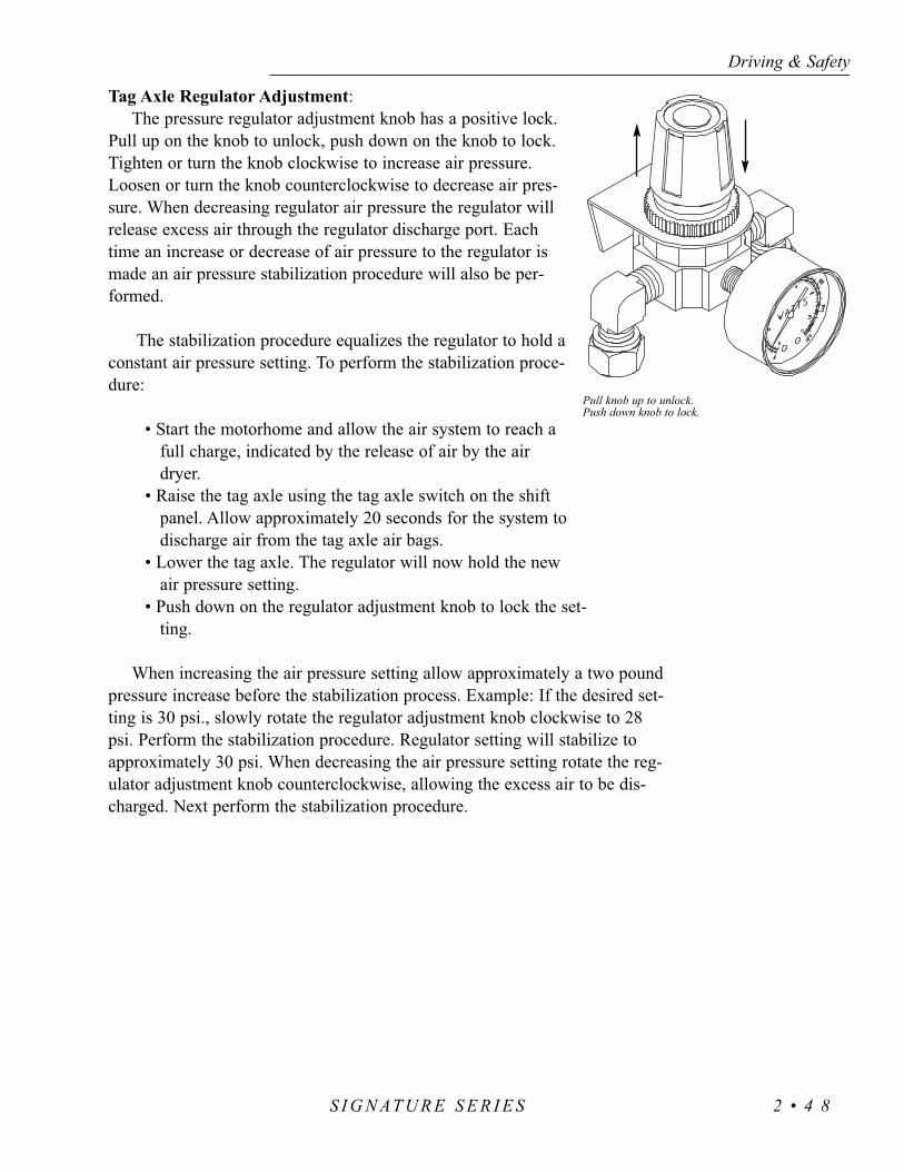
Tag Axle Regulator Adjustment:The pressure regulator adjustment knob has a positive lock.
Pull up on the knob to unlock, push down on the knob to lock.Tighten or turn the knob clockwise to increase air pressure.Loosen or turn the knob counterclockwise to decrease air pres-sure. When decreasing regulator air pressure the regulator willrelease excess air through the regulator discharge port. Eachtime an increase or decrease of air pressure to the regulator ismade an air pressure stabilization procedure will also be per-formed.
The stabilization procedure equalizes the regulator to hold aconstant air pressure setting. To perform the stabilization proce-dure:
• Start the motorhome and allow the air system to reach afull charge, indicated by the release of air by the airdryer.
• Raise the tag axle using the tag axle switch on the shiftpanel. Allow approximately 20 seconds for the system todischarge air from the tag axle air bags.
• Lower the tag axle. The regulator will now hold the newair pressure setting.
• Push down on the regulator adjustment knob to lock the set-ting.
When increasing the air pressure setting allow approximately a two poundpressure increase before the stabilization process. Example: If the desired set-ting is 30 psi., slowly rotate the regulator adjustment knob clockwise to 28psi. Perform the stabilization procedure. Regulator setting will stabilize toapproximately 30 psi. When decreasing the air pressure setting rotate the reg-ulator adjustment knob counterclockwise, allowing the excess air to be dis-charged. Next perform the stabilization procedure.
Driving & Safety------------------------------------------------------------------------------------------------------------------------------------------------------------------------------------------------------------------------------------------------------------------------------------------------------------------
S I G N AT U R E S E R I E S 2 • 4 8
Pull knob up to unlock.Push down knob to lock.
ScalesCertified public scales are located in a variety of places such as moving
and storage lots, farm suppliers with grain elevators, gravel pits, recyclingcompanies and large commercial truck stops.
If you are not aware of a nearby public scale, check the local area tele-phone book yellow pages under “scales-public” section or “weighers.” Anominal fee will be charged, but this is money wisely spent.
Weight scale types and weighing methods will affect the procedure used todetermine proper tire inflation pressure and axle loading. The size of somescales will allow the entire motorhome to fit on the scale, which will read theGVW with only one scale recording required. Other scales are designed toweigh only one axle at a time, which may require two or three scale readingsto determine the GAW or GVW total. Some scales will read only one wheelposition at a time due their physical size. Several scale readings may berequired to determine the GAW or GVW total.
Slide out equipped motorhomes will require each wheel position to beweighed. This is referred to as a four corner weigh. Slide out motorhomeswith a Tag Axle will require a six position weigh. This type of weighing pro-cedure will accurately determine what the correct tire inflation pressureshould be. Depending on the type of scale being used, several different scalereadings may be required.
NOTE: The most accurate method to determine proper tire pressure is afour corner weigh. A slide out motorhome will require each tire to beweighed independently. Weighing an axle will net the total weight carriedby that axle. When calculating the drive axle dual tire pressure using aindependent corner weigh method, divide the total weight by two todetermine the weight carried by each tire. When weighing the entiredrive axle, divide the total weight by four to determine the approximateweight carried by each tire.
Driving & Safety---------------------------------------------------------------------------------------------------------------------------------------------------------------------------------------------------------------------------------------------------------------------------------------------------------------------
S I G N AT U R E S E R I E S2 • 4 9

Example:The motorhome must be weighed fully loaded to obtain accurate scale readings
and to determine the proper tire pressure.
• Take the rear axle gross axle weight rating (GAWR) and divide it bytwo. Record the figure next to scale B GAWR ÷ 2. Example: If rearaxle GAWR is 13,000 lbs. GAWR ÷ 2 would be 6,500 lbs.
• Weigh the driver’s side rear corner (scale B) and record the scalereading next to gross axle weight (GAW) for scale B. Example:Scale B reading is 5100 lbs.
• Repeat procedure for the rest of the scale readings.• Add the GAWR from scales B and D and enter the sum next to the
final GAWR. Example 13,000. • Add the GAW from scales B and D and enter this sum next to the
final GCAW. Example: 10,000.• Compare scale readings GCAW against GAWR readings. All figures
on line 2 are not to exceed figures on line 1. • Use tire chart with scale reading to determine correct tire pressure.
NOTE: Scale readings and gross axle weight ratings are fictitious.Actual scale readings and gross axle weight ratings will vary withmodel and options.
Driving & Safety------------------------------------------------------------------------------------------------------------------------------------------------------------------------------------------------------------------------------------------------------------------------------------------------------------------
S I G N AT U R E S E R I E S 2 • 5 0
1.GAWR ÷ 2 (6,500)2.GAW (5100)
+
1. GAWR ÷ 2 (6,500)2. GAW (4,900)
ScaleB
ScaleD
= 2. GCAW (10,000)1.GAWR (13,000)
Rear
CD
AB
SCALE
Slide-out

Weighing a two axle non slide motorhome.• Record the gross axle weight ratings (GAWR) and
the gross vehicle weight rating (GVWR).• Weigh and record each wheel position or total axle
weight.• If necessary, adjust the payload so the GAWR is not
exceeded. Total combined weights must not exceedthe GVWR.
• Using the tire chart, locate the recommended airpressure for the weight carried by each tire. Adjustthe tire pressure accordingly.
Weighing a two axle slide out motorhome.• Slide rooms must be in the retracted position.• Record the gross axle weight ratings (GAWR) and
the gross vehicle weight rating (GVWR).• Weigh and record the weight placed on each tire. • If necessary, adjust the payload so the GAWR is not
exceeded. Total combined weights must not exceedthe GVWR.
• Using the tire chart, locate the recommended airpressure for the weight carried by each tire. Adjustthe tire pressure accordingly.
Driving & Safety---------------------------------------------------------------------------------------------------------------------------------------------------------------------------------------------------------------------------------------------------------------------------------------------------------------------
S I G N AT U R E S E R I E S2 • 5 1
GAWR ÷ 2GAW
GAWR ÷ 2GAW
+ =GCAW
GAWR
ScaleC
ScaleA
Front
GAWR (Rear) GAWR (Front)
GAW (Front)GAW (Rear) =
=
GCAW
GCVW
+
+
CD
AB
SCALE
Slide-out
GAWR ÷ 2GAW
+
GAWR ÷ 2GAW
ScaleB
ScaleD
=GCAWGAWR
Rear
SCALE

Weighing a tag axle non slide motorhome.• Record the gross axle weight ratings (GAWR)
and the gross vehicle weight rating (GVWR).• Weigh and record each corner or total axle
weight.• If necessary, adjust the tag axle regulator to
compensate for the payload carried by the tag,drive and front axles.
• Perform the regulator stabilization procedure. • If necessary, adjust the payload so the GAWR
is not exceeded. Total combined weights mustnot exceed the GVWR.
• Using the tire chart, locate the recommendedair pressure for the weight carried by each tire.Adjust the tire pressure accordingly.
Weighing a tag axle slide out motorhome.• Slide rooms must be in the retracted position.• Record the gross axle weight ratings (GAWR)
and the gross vehicle weight rating (GVWR).• Weigh and record each side of each axle. • If necessary, adjust the tag axle regulator to
compensate for the payload carried by the tag,drive and front axles.
• Perform the regulator stabilization procedure. • If necessary, adjust the payload so the GAWR is
not exceeded. Total combined weights must notexceed the GVWR.
Driving & Safety------------------------------------------------------------------------------------------------------------------------------------------------------------------------------------------------------------------------------------------------------------------------------------------------------------------
S I G N AT U R E S E R I E S 2 • 5 2
SCALE
DE
AB
F
C
SCALE
Slide-outSlide-out
TAG DRIVE FRONT
ScaleC
ScaleF
ScaleE
ScaleB
ScaleA
ScaleD
GAWR ÷ 2
GAW
+
GAWR ÷ 2
GAW
=GCAW
GAWR
GAWR ÷ 2
GAW
+
GAWR ÷ 2
GAW
=GCAW
GAWR
GAWR ÷ 2
GAW
+
GAWR ÷ 2
GAW
=GCAW
GCVW
GAWR (Tag) GAWR(Rear) GAWR (Front)
GAW (Rear) GAW (Front)GAW (Tag)
+
+
+
+
=
= GCAW
GCVW

Driving & Safety---------------------------------------------------------------------------------------------------------------------------------------------------------------------------------------------------------------------------------------------------------------------------------------------------------------------
S I G N AT U R E S E R I E S2 • 5 3
Monaco Coach Corporation is not the author of this chart and makes no representation or warranty concerning the accuracy of the information dis-closed by the chart. Monaco is not responsible for the accuracy of the information disclosed or for any errors within the Tire Inflation Chart.
Check the tire pressure regularly. If a tire is punctured by a nail or screw,creating a slow leak, it may eventually be spotted if it is a front tire or anoutside rear dual. However, if there is a leak on an inside dual the chances ofnoticing it without an air pressure check are very slim. If you begin drivingunaware that an inside dual tire has a low air pressure or is flat, very quickly(in most cases a few miles) the outside rear tire (next to the low air pressuretire) will heat up from carrying double the load, leading to failure of the out-side dual tire. The motorhome will end up with two tires flat on the sameside on the same axle.
The air pressure should be checked every two weeks or at least once amonth and before any major trip. The RV tire air pressure should be checkedevery “drive” morning on both long and short trips (driving a day or less).The tires should be checked before leaving on a trip and again before youstart your trip home. If the motorhome is stored for any length of time the airpressure should be checked prior to storage. More importantly, check the tirepressure when it is pulled out of storage.
Check the tire pressure when the tires are “cold” and have not been driv-en for more than one mile. The stated load capacity for a given cold inflationpressure is based on ambient outside temperature. If you must check the tireswhen they are warm or hot, allow for a slight increase in air pressure andmake sure they are within a couple of pounds of each other on the same axle(does not apply to slide-out equipped motorhomes). Never let air out of a hottire.
To check or maintain the inflation pressure in the tires, use a quality trucktire air gauge which has an angle dual head. This type of gauge will allowyou to check inflation of the inner dual wheel which has the valve stempointing outward. The outer wheel has the valve stem pointing inward.Nothing should restrict the ability to check the tire’s air pressure daily whentraveling in the motorhome. Pressure sealing valve caps should always beused to prevent air from escaping from the valve stem. If there are valvestem extension hoses, make sure they are good quality stainless steel braidreinforced and are securely anchored to the outer wheel.
Optimum tire performance is achieved with proper inflation pressures forthe loads being carried. The air pressure of all tires should be checked andcorrected prior to travel, or daily if in full time use.
Tires of different patterns should not be mixed on the same axle. The dif-ference in tractive force could cause rear end gear fight and mechanical dam-age to the drive train. Tires of different size or construction must never bemixed on the same axle.
Higher than recommended pressure can cause:• Hard ride.• Tire bruising or carcass damage.• Rapid tread wear at center of tire.
Driving & Safety------------------------------------------------------------------------------------------------------------------------------------------------------------------------------------------------------------------------------------------------------------------------------------------------------------------
S I G N AT U R E S E R I E S 2 • 5 4
Inspecting &Pressure

Lower than recommended pressure can cause:• Tire squeal on turns.• Rapid and uneven wear on the edges of the tread.• Tire rim bruises and rupture.• Tire cord breakage.• High tire temperatures.• Reduced handling.• High fuel consumption
Unequal tire pressures on same axle can cause:• Uneven braking, swerve of acceleration.• Steering lead, torque steer.• Reduced handling.
The useful tire life of your tire is achieved by the uniform wear for all tires.This can be increased with tire rotation. The first tire rotation is the most impor-tant. The tire rotation pattern used for the motorhome should be evaluated bythe tire manufacturer. Any unusual or unique wear pattern which may havedeveloped should be evaluated before rotation. Misalignment, imbalance orother mechanical problems may exist and will need corrected prior to rotation.
The tire rotation should be performed every 6,000 to 8,000 miles, or at anysign of uneven wear. After a tire rotation, the inflation pressures should bechecked and adjusted for the actual loads of the wheel position accordingly.
Tires are covered by the tire manufacturer. Monaco Coach Corporation is notresponsible for tire wear.
Extreme caution must be taken to ensure that the tires are fully supportedwhen placing blocks under the tires. The load on the tire should be evenly dis-tributed on the block. In the case of dual tires, distribute the load evenly onblocks for both tires. If not properly blocked, the steel cables in the sidewall ofthe tires may be damaged and could lead to premature fatigue of the sidewall.
Proper Cleaning:Road oil will cause deterioration of the rubber. Dirt buildup will help hold
chemicals in the air next to the tire and will also cause deterioration.When cleaning any rubber product, proper care and methods in cleaning
must be used to obtain the maximum service years out of the tires. Use a softbrush and a mild detergent to clean the tires. If a dressing product is used to“protect” the tires from aging, use extra care and caution. Tire dressings thatcontain petroleum products or alcohol may cause deterioration or cracking.
In many cases it is not the dressing that causes a problem but the chemicalreaction that subsequently occurs. When these same dressing products are used
Driving & Safety---------------------------------------------------------------------------------------------------------------------------------------------------------------------------------------------------------------------------------------------------------------------------------------------------------------------
S I G N AT U R E S E R I E S2 • 5 5
Tire Rotation
Blocking- When Leveling

on a passenger car tire that is replaced every three to four years, it is rare tosee a major problem. However, in most cases, RV tires may last longer dueto limited annual mileage and exposure.
The RV is designed for recreation not long-term storage. However, unlessyou are living in your motorhome full-time you will have a need to store it.Rubber tires age faster when not being used. A cool, dry, sealed garage is thepreferred method of storage. Many RV’s are stored outside in the elements.Some storage surfaces may cause tires to age prematurely. Placing a barrier(i.e. cardboard, plastic or plywood) between the tire and the storagefloor/ground surface will help to protect the tires.
There are a few steps that can be taken to reduce the aging effects fromlong-term storage or a non-use period. Thoroughly clean the tires. Cover thetires to block direct sunlight and ultraviolet rays. Store the RV out of a highozone area. Failure to take these steps can cause early deterioration andshorten the life of the tires.
NOTE: When the motorhome is stored the tires should be inflated tomaximum inflation pressure as indicated on the sidewall of the tire.
Before removing the motorhome from long-term storage thoroughlyinspect each of the tires. This means a close examination of each tire’s treadarea and air pressure. If the pressure check indicates the tires have lost airduring storage, inflate them to the correct pressure for the current load beforeputting the motorhome into service.
Driving & Safety------------------------------------------------------------------------------------------------------------------------------------------------------------------------------------------------------------------------------------------------------------------------------------------------------------------
S I G N AT U R E S E R I E S 2 • 5 6
Storage of Tires -Long Term
INCORRECTSingles
Only a portion of the tire issupporting the full load.
One tire or a portion of one tireis supporting the full load.
CORRECTSingles
Tire Footprints
Dual Tire Footprints
Duals
Duals
One tire or a portion of the two tire supporting the full load.
Tire "Blocking" Methods

If you have a flat tire it is recommended to call for roadside service. The sizeand weight of the motor home and its tires requires proper equipment to changethe tire. A professional service technician will have the proper equipment andtraining to repair or replace the tire. In the case of sudden tire failure avoidheavy braking. Hold the steering wheel firmly and gradually decrease speed.Slowly move to a safe off-road place, which should be a firm level spot. Turnthe ignition off and turn the hazard flasher system ON. Goodyear Tire Companyhas an emergency number which offers 24 hour assistance. To contact Goodyearcall (877) 484-7376. The old tire should be saved for warranty.
Hub Piloted Mounting:• Before using flange nuts that have already been used in service, apply 2
drops of oil at one point between the flange and hex. This will allowparts to rotate freely and provide the proper clamping force when tight-ened. Use any common lubricant typically used for fasteners. Examplesare motor oil and general purpose lubricating oils. Excessive lubricant isnot desirable, this will not improve the nut performance. Excessive lubri-cant makes the nuts hard to handle, attracts dirt to the nuts and maycause unsightly appearance to the wheel. Only used nuts need to belubricated.
• Since flange nuts generate higher clamping force always use grade eightstuds with hub mount wheels.
• Before installing the wheels, lubricate the hub pilot pads with a drop ofoil to prevent galling. Do not lubricate any other wheel or hub surface.
• For a hub with intermittent pilot pads, position a pad at twelve o’clock tocenter the wheel to reduce runout.
NOTE: Loosen and tighten lug nutsin a star pattern sequence. Sequencetighten to 50 ft lb first, then sequencetighten to 500 lb (over tightening cancause distortion).
Front Wheels:Slide the front wheel over the studs,
being careful not to damage stud threads.Snug the nuts in sequence, do not tightenthem fully until all have been seated.Tighten the nuts to 500 ft.lbs in sequence(as shown in the illustration).
Driving & Safety---------------------------------------------------------------------------------------------------------------------------------------------------------------------------------------------------------------------------------------------------------------------------------------------------------------------
S I G N AT U R E S E R I E S2 • 5 7
In Case of Flat Tire

Dual Rear Wheels:Slide the inner dual wheel over the studs, being careful not to damage the
stud threads. Align the handholds for valve access and slide the outer dualwheel over the studs, again being careful not to damage the stud threads.
Snug the nuts in sequence, do not tighten them fully until all have beenseated. Tighten the nuts to 500 ft. lbs. using the sequence as shown in the illus-tration. The hub mount wheels use two piece flange cap nuts for both front andrear applications. No inner cap nuts are required.
Torque the Nuts Properly:• Be sure to tighten the wheel nuts to the recommended nut torque. Do not
over tighten.• Maintain the nut torque at the recommended level through planned peri-
odic checks or at 10,000 miles intervals, whichever comes first.• If air wrenches are used they must be periodically calibrated for the
proper torque output. Use a torque wrench to check the air wrench out-put and adjust the line pressure for the correct torque.
• Clean frequently with high pressure water from a hose. The use of milddetergent will speed the cleaning process. Do not use harsh alkalis, alco-hol or acidic cleansers. A secondary hand washing with a soft cloth maybe required to remove some stubborn road films.
• When the tires are removed the entire wheel must be cleaned and inspect-ed. With a wire brush or sandpaper remove dirt, corrosion or any foreignmaterials from the tire side of the rim. Do not use a wire brush or otherabrasive substances to remove dirt and corrosion on the polished surfaceof the wheel.
• To maintain the original appearance of the aluminum wheels the follow-ing procedures are recommended:
1. After installing new wheels (prior to operating your motorhome) use asponge, cloth or soft fiber brush to wash the exposed wheel surfaceswith a mild detergent/warm water solution.
2. Rinse thoroughly with clean water.3. Wipe dry to avoid water spots.4. Use a high quality, non-abrasive polish to remove stubborn road tars,
insects or hard to remove deposits.5. To protect the appearance surface on Accu-Forge wheels, wax the
cleaned surface with a high quality car wax.6. Clean the aluminum wheels as frequently as required to maintain their
appearance.
Driving & Safety------------------------------------------------------------------------------------------------------------------------------------------------------------------------------------------------------------------------------------------------------------------------------------------------------------------
S I G N AT U R E S E R I E S 2 • 5 8
Care & Maintenanceof Aluminum Wheels
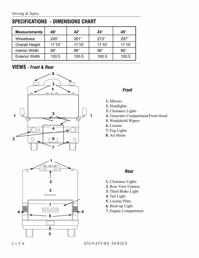
Driving & Safety---------------------------------------------------------------------------------------------------------------------------------------------------------------------------------------------------------------------------------------------------------------------------------------------------------------------
S I G N AT U R E S E R I E S2 • 5 9
6
1
5
4 4
7
1. Mirrors2. Headlights3. Clearance Lights4. Generator Compartment/Front Hood5. Windshield Wipers6. License7. Fog Lights8. Air Horns
1. Clearance Lights2. Rear View Camera3. Third Brake Light4. Tail Light5. License Plate6. Back-up Light7. Engine Compartment
VIEWS - Front & Rear
SPECIFICATIONS - DIMENSIONS CHART
1
2 6
1
8
5
4
7
Front
Rear
Measurements 40’ 42’ 43’ 45’
Wheelbase 245” 261” 273” 297”Overall Height 11’10” 11’10’ 11’10’ 11’10’Interior Width 96” 96” 96” 96”Exterior Width 100.5 100.5 100.5 100.5
3
2
3

Driving & Safety------------------------------------------------------------------------------------------------------------------------------------------------------------------------------------------------------------------------------------------------------------------------------------------------------------------
S I G N AT U R E S E R I E S 2 • 6 0
1 2
3
9
10
4
5 67
8
1
3 2
1. 12 Volt Distribution Panel2. Radiator Grill3. Egress Window4. Roof Air Conditioner5. LP-Gas Compartment
6. Water Control Panel Service Center7. Storage Compartments8. Awnings9. Gravity Fill
10. Shore Cord (behind the door)
1. Refrigerator Vent2. Battery Compartment3. Engine Exhaust4. Fuel Inlet
5. Docking Lights6. Water Tank Access7. Satellite8. Awnings
VIEWSRoadside
Curbside
5
8
45
6
7

The “Viper” security system is designed to provide years of trouble freeoperation. The only maintenance required is changing the battery in the remoteonce a year. The range of the remote will decrease and the green LED will dimwhen the battery becomes weak. The two remote transmitters (key fobs) areprogrammed to the receiver using a computer based “Learn Routine.” The learnroutine will dictate how the system operates. The Standard transmitter configu-ration is set at installation. An authorized dealer can customize the transmitterconfiguration.
Transmitter Configuration-Standard
AUX Button - Controls the silent mode function.
Lock Button - Controls the arming function.
Green LED - Indicates power at the Key Fob.
Unlock Button - Controls the disarming function.
Horn Button - Controls the panic function.
Using the SystemArming:
The system is armed by pressing the LOCK button on the transmitter remotefor one second. When armed, the system will “chirp” once. The parking lightsflash once, the entry door and selected bay doors will lock. The red LED systemstatus light flashes once per second indicating the system is armed and function-ing properly.
If the system chirps twice when armed, the red LED will flash in groups.These groups are system diagnostic codes. The second chirp is a “BypassNotification.” Bypass notification will arm the system however, one or moresystem sensors are “open.” The system arming mode can be changed to“Passive Arming.” In passive arming mode and the ignition is OFF, thirty sec-onds after the entry door is opened and closed, the system begins a countdown.The red LED flashes twice per second. An audible chirp will occur twenty sec-onds after the last protected door or zone is closed. The system will then armand lock the doors ten seconds later.
When armed:• The System will use “Warn Away” chirp signal for impact sens-
ing. Light impact, siren will chirp. • A Heavy impact, continuous alarm will sound.• Opening any door, alarm will chirp for three seconds followed by
Driving & Safety---------------------------------------------------------------------------------------------------------------------------------------------------------------------------------------------------------------------------------------------------------------------------------------------------------------------
S I G N AT U R E S E R I E S2 • 6 1
SECURITY SYSTEM
AUX
AUX
AUXAUX

a continuous alarm.
Disarming:The system is disarmed by pressing the unlock button.
The parking lights flash twice, the alarm will chirp twiceand the doors unlock. Any additional chirps are “TamperAlert.” When the system chirps four or five times duringdisarming, the red LED will blink the code for the zonethat has been tampered with.
Panic Mode:Press the horn button for one second. The siren will
sound and the parking lights will flash for the pro-grammed duration. The panic mode can be exited at anytime by pressing the horn button again. If you are threatened, thisis helpful in attracting attention to the motorhome.
Silent Mode: Prior to arming or disarming the system, the confirmation chirp(s) can be
temporarily turned OFF. Press the AUX button for less than one second priorto arming or disarming the system. System will either Arm or Disarm silent-ly. The chirp will be silenced only once each Arm or Disarm cycle.
NOTE: A Warn Away chirp will not sound when the system is armed inSilent Mode. A heavy impact will sound a continuous alarm.
Valet Mode:This feature is useful in servicing, washing or storing the vehicle. The
Valet Mode will not allow the system to sound an alarm. While in Valetmode the remote will lock and unlock the doors. The red LED status light isa solid glow in the Valet Mode. There are two ways to access the ValetMode. One is with the key fob, the other is with the Valet/Program button.
Driving & Safety------------------------------------------------------------------------------------------------------------------------------------------------------------------------------------------------------------------------------------------------------------------------------------------------------------------
S I G N AT U R E S E R I E S 2 • 6 2
1. Valet/Program button.2. Red LED status light.

Entering Valet Mode with Key Fob:1. Open entry door.2. Press the lock button.3. Press the unlock button.4. Press the lock button again.5. Ensure the red LED is a steady glow.
Entering Valet Mode with Valet/Program Button:1. Turn the ignition ON.2. Turn the ignition OFF.3. Press and hold the Valet/Program button ten seconds and release.4. Ensure the red LED is a steady glow.
Multi-Level Security ArmingThis feature applies to one arming cycle only. The selection of which sensor
inputs are active and which are bypassed can be set when arming. Press the lockbutton within five seconds after arming. Each time the lock button is pressedanother zone or zones are bypassed. Reset the system to monitor all zones byturning the ignition key on.
Table of Zones:• Zone One is the pin switches.• Zone Two is the Warn away.• Zone Three is the Entry Door.• Zone Four is the Bay Doors.• Zone Five is the Ignition.
Quick Reference Guide:• Lock - Arms or activates the system.• Unlock - Disarms the system.• Lock - While driving will arm the system.• Ignition ON and the Valet button pressed will disarm without a
transmitter.• Ignition ON, then OFF, then pressing the Valet button for ten sec-
onds enters or exits the Valet Mode.• Press and hold the HORN button for one second to enter the
Panic Mode.• Press the HORN button to exit the Panic Mode.• Press the AUX button for Silent Mode Activation.
Tips:• Remember the location of the Valet/Program button.• Know the number of Valet/Program button pulses for disarming.• There is a 24 hour support number located on the back of the key
fob.• The headlights will only flash when using the Key Fob.
Driving & Safety---------------------------------------------------------------------------------------------------------------------------------------------------------------------------------------------------------------------------------------------------------------------------------------------------------------------
S I G N AT U R E S E R I E S2 • 6 3

• The range of the remote key fob is about 1,200 feet.
Troubleshooting• Valet/Program not responding - Ensure the button is plugged into
the blue port of the receiver.• Red Status LED doesn’t work - Ensure the LED is plugged into
the correct socket.• Shock Sensor won’t trigger alarm - Ensure NPC system has not
triggered.• System has no power - Ensure the 15 amp fuse (front run panel)
is not blown.• The system is not responding to the remote - Ensure the Valet
mode is not entered.
Changing the Programming- Entering the “Learn Routine”
The following information is provided for changing the programming fea-tures. It should be used only by an authorized service center.
1. Open the door.2. Turn ignition ON, then OFF.3. For menu selection: Press and hold
the Valet/Program button.4. Select a feature.5. Program a feature.6. Release the Valet/Program button.
When the feature is programmed:• Other features can be programmed with-
in the same menu.• Another menu can be accessed.• The learn routine can be exited.
To access another feature in the same menu:• Press the valet/program button the number of
times necessary to advance to the desired fea-ture.
• Press the valet/program button and HOLD.
Driving & Safety------------------------------------------------------------------------------------------------------------------------------------------------------------------------------------------------------------------------------------------------------------------------------------------------------------------
S I G N AT U R E S E R I E S 2 • 6 4

Selecting another menu:• Press and hold the valet/program button.• The system will advance and chirp is audible to accessed menu
after three seconds.
Exiting the Learn Routine:This can be done in one of four ways:
1. Close the door.2. Switch ignition ON.3. Do not respond for longer than 15 seconds.4. Press the Valet/Program button an excessive number of times.
System Features MenusThe system features are broken into two separate menus. Both can be
accessed to customize the system by an authorized dealer. Monaco has pro-grammed the following features when the system was installed at the factory.
NOTE: *Bold indicates the factory default settings.
Basic Features - Menu OneActive/Passive Arming: Select *ACTIVE. When active arming is selected,the system will only arm with the transmitter. Passive arming will allow auto-matic arming after the door is closed.
Chirp ON/OFF: Select *Chirp ON. Allows control of the chirp which con-firms arming or disarming.
Ignition Controlled Door Locks ON/OFF: Select *ON. When turned on thedoors will lock three seconds after the ignition is turned ON and unlock whenthe ignition is turned OFF.
Active/Passive Locking: *Active selected. Active locking means the doorswill not lock when the system is passively armed. Passive locking means thedoors will lock when the system is passively armed.
Panic with the Ignition ON: Turned *OFF. Many states prohibit a siren from sounding in a moving vehicle. This feature is designed to comply with thoselaws and regulations.
Door Lock Pulse Duration: *.8
Forced Passive Arming ON/OFF: Forced Passive Arming *OFF. ForcedPassive Arming will occur one hour after the ignition is turned OFF. When thisfeature is turned on it will force passive arming, even if a zone is left open orinvalid.Automatic Engine Disable (AED) ON/OFF: *Not wired.
Driving & Safety---------------------------------------------------------------------------------------------------------------------------------------------------------------------------------------------------------------------------------------------------------------------------------------------------------------------
S I G N AT U R E S E R I E S2 • 6 5

Armed While Driving/Vehicle Recovery System (VRS): Turned *OFF.
Code Hopping ON/OFF: Turn *ON. This enables a mathematical formulato change the code each time the transmitter and receiver communicate.
Advance Features - Menu TwoSiren/Horn Honk: *Continuous.
Siren Duration 30/60 Seconds: *180 seconds.
Nuisance Prevention Circuitry (NPC) ON/OFF: With *OFF selected. This enables the system to respond to repeated triggers on the sensor inputs indef-initely. When a zone triggers three times in one hour, it may be necessary toswitch to ON. This will bypass that zone for an hour. That hour will deter-mine if that zone can trigger the system. If that zone triggers in the hour itwill reset the one hour timer. If that zone does not trigger in the hour thezone will become active and allow the system to be triggered again.
Progressive Door Trigger ON/OFF: *ON.
Valet Pulse Count 1 to 5 Pulses: *ONE. This is the number of times the Valet/Program button must be pressed before disarming the system.
Door Trigger Error Chirp ON/OFF: *ON.
Ignition Controlled Dome light Supervision ON/OFF: *Not wired.
Double Pulse Unlock ON/OFF: *OFF.
Channel 3 Validity/Latched/Latched Rest with Ignition/30 Second.
Timed/Second Unlock Output: *ON AUX Channel 3.
NOTE: *Bold indicates the factory default settings.
Driving & Safety------------------------------------------------------------------------------------------------------------------------------------------------------------------------------------------------------------------------------------------------------------------------------------------------------------------
S I G N AT U R E S E R I E S 2 • 6 6

Statistics show that most fire casualties are not caused by direct flame, butby less visible smoke (products of combustion). The smoke detector responds toboth visible and invisible products of combustion. The smoke detector willautomatically return from alarm to normal state when the reason for activation,the presence of smoke, is completely removed. Common causes of fires aresmoking in bed, leaving children unattended or using flammable cleaning flu-ids. Please be safety conscious and avoid unnecessary risk.
WARNING: There is no way to insure there will be no injuryor loss of life in a fire; however, the smoke detector is intendedto help reduce the risk of tragedy. Additional smoke detectorsmay help to reduce the risk. Proper use and care of the smokedetector could save lives.
To test the electronics of the alarm, press the test button on the cover of thesmoke alarm for a few seconds. The smoke alarm will sound by making a con-tinuous loud beep. To complete the test sequence release the button and thealarm should stop.
NOTE: Test the smoke alarm operation after the motorhome hasbeen in storage, before each trip and at least once a week during use.
Vacuum the slots in the cover and sides with a soft brush attachment everymonth. The smoke alarm should be cleaned every six months to help keep theunit working efficiently.
The battery should power the smoke alarm for at least one year under nor-mal use. When the battery reaches the end of its normal life a low battery warn-ing (intermittent beeping) will indicate the need for battery replacement. It maybe practical to replace the battery during the time changes in the spring and fall.
If the alarm does not sound when the test button is pushed, or with a smoketest, try the following:
• Inspect for obvious damage.• Check for the recommended battery type. • Check the battery for proper connection or replace
the battery if needed.• Gently vacuum as recommended.
If these procedures do not correct the problem, do not attempt repairs. If thesmoke alarm is within the warranty period and the terms indicate the nature ofthe problem, return the unit to your dealer. Smoke detectors beyond the warran-
Driving & Safety---------------------------------------------------------------------------------------------------------------------------------------------------------------------------------------------------------------------------------------------------------------------------------------------------------------------
S I G N AT U R E S E R I E S2 • 6 7
SMOKE DETECTOR
How to Test
Maintenance
Troubleshooting

ty period cannot be economically repaired.Abnormal air conditions may cause the highly sensitive smoke alarm to
give a false alarm. If no fire is apparent ventilate the room and/or blow freshair into the motorhome until the alarm stops. Once cleared, the smoke alarmwill automatically reset. Dust can lead to excessive sensitivity. Vacuum asneeded.
Provided for safety is a gas detector. This gas detectorwill detect both LP Gas and Methane Gas. LiquefiedPetroleum (LP) Gas is heavier than air, Methane Gas islighter than air. LP Gas will settle to the lowest point,generally the floor of the motorhome. Methane Gas willrise. The gas detector is also sensitive to other fumessuch as hair spray, of which most contain butane as thepropellant. Butane, like propane is heavier than air andwill settle to the floor level where it will be detected.When this occurs, press reset button to stop the alertsound for 60 seconds.
The other combustibles which will be detectedinclude alcohol, liquor, deodorants, colognes, perfumes,wine, adhesives, lacquer, kerosene, gasoline, glues, mostcleaning agents and propellant of aerosol cans. Most arelighter than air in their vapor state and will only bedetected when the motorhome is closed up.
Upon first application of power the LED will flash yellow for 3 minuteswhile the detector is stabilizing. At the end of the start cycle the LED willturn Green, indicating full operation. If the detector senses unsafe levels ofgas it will immediately sound an alarm.
The gas detector operates on 12 Volt DC, with a current draw less than1/10th of one amp.
CAUTION: This detector will not alarm during the 3 minute warmup cycle.
Press the TEST switch any time during the warm up cycle or while innormal operation. The LED should flash RED and the alarm should sound.Release the switch. This is the only way you should test the detector. The testfeature checks full operation of the detector.
WARNING: Test the operation of this detector after the motorhome hasbeen in storage, before each trip and at least once per week during use.
Driving & Safety------------------------------------------------------------------------------------------------------------------------------------------------------------------------------------------------------------------------------------------------------------------------------------------------------------------
S I G N AT U R E S E R I E S 2 • 6 8
LP-GAS DETECTOR
LP-Gas Detector
Operation
Testing

The Red LED will flash and the alarm will sound whenever a dangerouslevel of propane or methane gas is detected. The detector will continue to alarmuntil the gas clears or the Test/Mute switch is pressed.
Procedures To Take During An Alarm:1. Turn off all gas appliances, (stove, heaters, furnace), extinguish
all flames and smoking material. Evacuate, leave doors and win-dows open.
2. Turn off the propane tank valve. 3. Determine and repair the source of the leak. Seek professional
help if necessary.
CAUTION: Do Not re-enter until the problem is corrected.
Alarm Mute:Press the Test-Mute button when the detector is in alarm.
1. The Red LED will continue flash and the alarm will beep every30 seconds until the gas level has dropped to a safe level.
2. The LED will flash Green until the end of the Mute cycle.3. If dangerous gas levels return before the end of the mute cycle,
the alarm will beep 4 times and return to phase 1. 4. After 2 minutes the detector will return to normal operation
(solid Green) or resound the alarm if dangerous levels of gasremain in the area.
Fault Alarm:Should the microprocessor sense a fault in the gas detector, a fault alarm will
sound twice every 15 seconds. The LED will alternately flash Red to Green andthe MUTE switch will not respond to any command. The gas detector must berepaired or replaced.
1. Vacuum the dust off the detector cover weekly (more frequentlyin dusty locations) using the soft brush attachment of your vacu-um.
2. Do not spray cleaning agents or waxes directly onto the frontpanel. This action may damage the sensor, cause an alarm orcause a detector malfunction.
Driving & Safety---------------------------------------------------------------------------------------------------------------------------------------------------------------------------------------------------------------------------------------------------------------------------------------------------------------------
S I G N AT U R E S E R I E S2 • 6 9
Alarm
Care

The motorhome is equipped with a carbonmonoxide detector. Carbon monoxide (CO)is a colorless, odorless and tasteless gas.Even low levels of CO have been known tocause brain and other vital organ damage inunborn infants, with no effect on the mother.In cases of mild exposure the symptoms mayinclude: a slight headache, nausea, vomitingand fatigue. Symptoms for medium exposuremay include a severe throbbing headache,drowsiness, confusion and fast heart rate.Extreme exposure can result in unconscious-ness, convulsions, cardio-respiratory failureand death. Young children and householdpets may be the first effected. The CO detector is designed to detect the toxicCO fumes that result from vehicle exhaust and incomplete combustionsources like a furnace, gas stove or water heater. Consequently, it is uncom-mon for household smoke from cigarettes or normal cooking to cause thealarm to sound.
NOTE: Activation of this device indicates the presence of carbon monoxide (CO) which can be fatal. A concentration of above 100 PPMwill cause a warning condition. Individuals with medical problems mayconsider using detection devices with lower carbon monoxide alarmingcapabilities. Prolonged exposure to the horn at a close distance may beharmful to your hearing.
The detector is equipped with a self-cleaning CO sensor and requires aten minute initial warm-up period to clean the sensor element and achieve stabilization. The green power light should be lit when the power is on. If thelight is not lit, turn off the power and check all wire connections. If thepower is on and the connections are correct but the indicator still does notlight, the detector should be returned for service. Do not attempt to fix thedetector. The indicator light displays a specific color to monitor the conditionsas follows:
• Green - indicates “ON” or normal condition. The CO detectorhas power and is sensing air for the presence of CO gas. Thealarm horn will not sound.
• Yellow - indicates a “trouble” or malfunction condition. Thealarm horn will sound and cannot be reset by theTEST/RESET button. The CO detector is not working proper-
Driving & Safety------------------------------------------------------------------------------------------------------------------------------------------------------------------------------------------------------------------------------------------------------------------------------------------------------------------
S I G N AT U R E S E R I E S 2 • 7 0
CARBON MONOXIDE DETECTOR
Carbon monoxide detector.
OperatingInstructions
ly and must be immediately replaced or repaired.
• Red - indicates an “alarm condition.” The detector has sensed thepresence of a hazardous level of carbon monoxide. The alarmhorn will sound continuously until reset by the RESET switch.
When the alarm sounds have the detector and the motorhome checked by anauthorized service technician as soon as possible. Never disconnect a CO detec-tor to silence an annoying alarm. Evacuate the motorhome immediately whenthe RED light is lit and the alarm sounds. Do a head count to check that all per-sons are accounted for. Call the nearest fire department and ask them to deter-mine the source of the carbon monoxide. Do not re-enter the motorhome until ithas been aired out and the problem corrected.
Test the carbon monoxide detector operation after the motorhome has beenin storage, before each trip and at least once a week during use. Test the alarmby holding the test button in until the alarm sounds. The alarm will stop beepingin about 30 seconds.
Use a vacuum cleaner to remove dust or any other buildup on the detector.Do not wash. Wipe the detector with a damp cloth and dry it with a towel. Donot open the detector for cleaning. Do not paint the detector. It is recommendthat the carbon monoxide detector should be replaced every 10 years.
Driving & Safety---------------------------------------------------------------------------------------------------------------------------------------------------------------------------------------------------------------------------------------------------------------------------------------------------------------------
S I G N AT U R E S E R I E S2 • 7 1
Alarm
Testing
Cleaning
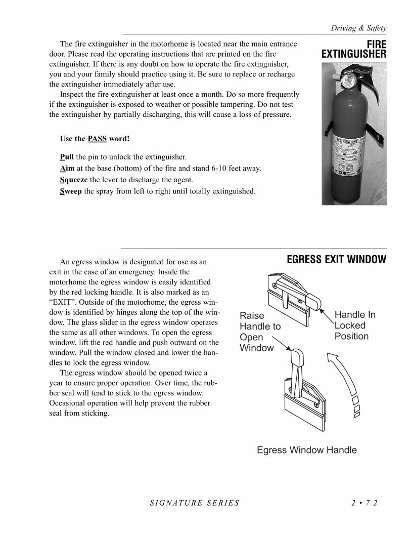
The fire extinguisher in the motorhome is located near the main entrancedoor. Please read the operating instructions that are printed on the fire extinguisher. If there is any doubt on how to operate the fire extinguisher,you and your family should practice using it. Be sure to replace or rechargethe extinguisher immediately after use.
Inspect the fire extinguisher at least once a month. Do so more frequentlyif the extinguisher is exposed to weather or possible tampering. Do not testthe extinguisher by partially discharging, this will cause a loss of pressure.
Use the PASS word!
Pull the pin to unlock the extinguisher.Aim at the base (bottom) of the fire and stand 6-10 feet away.Squeeze the lever to discharge the agent.Sweep the spray from left to right until totally extinguished.
An egress window is designated for use as anexit in the case of an emergency. Inside themotorhome the egress window is easily identifiedby the red locking handle. It is also marked as an“EXIT”. Outside of the motorhome, the egress win-dow is identified by hinges along the top of the win-dow. The glass slider in the egress window operatesthe same as all other windows. To open the egresswindow, lift the red handle and push outward on thewindow. Pull the window closed and lower the han-dles to lock the egress window.
The egress window should be opened twice ayear to ensure proper operation. Over time, the rub-ber seal will tend to stick to the egress window.Occasional operation will help prevent the rubberseal from sticking.
Driving & Safety------------------------------------------------------------------------------------------------------------------------------------------------------------------------------------------------------------------------------------------------------------------------------------------------------------------
S I G N AT U R E S E R I E S 2 • 7 2
FIREEXTINGUISHER
EGRESS EXIT WINDOW

Driving & Safety---------------------------------------------------------------------------------------------------------------------------------------------------------------------------------------------------------------------------------------------------------------------------------------------------------------------
S I G N AT U R E S E R I E S2 • 7 3
NOTES

S I G N A T U R ESECTION 3CARE & MAINTENANCE
3
EXTERIOR CARE • 76Corrosion • 76Washing • 76
Drying • 77Waxing • 77
Tire Care • 78Care & Maintenance of Aluminum Wheels • 78
Bright Metal • 79Maintenance - Exterior • 79
Roof Care & Seal Inspections • 79INTERIOR CARE • 81
Fabrics • 81Specifications Charts • 83
Vinyl • 86Leather • 88
Floors - Carpet Cleaning • 89Tile • 90
Wall Coverings • 91Countertops • 92
Windows • 93Mini-Blind • 94STORAGE • 94
Short Term • 94Long Term • 95
CHECKLIST - Winter Storage • 98


The most common cause of corrosion to the motorhome is the accumula-tion of road salts, grime and dirt. These elements, combined with moisture,may possibly cause early component failure. Salt air and fog from coastaltrips can greatly accelerate the corrosion process. Corrosive materials collect-ed from roadways accumulate on the undercarriage, around wheel openingsand on the radiator charge air cooler package. These areas need to be cleanedperiodically to help prevent component failure due to corrosion. If themotorhome is driven in areas where road salts are used it should be washedat least once a week. Otherwise, it is recommended to hose off the undercar-riage area at least once a month to help minimize the corrosion process. Highpressure washers or steam cleaners are the most affective way of cleaning offthe underside and inside wheel openings. Avoid directly spraying the paint-ed surface with a high pressure washer. Remove road debris and mud thathas accumulated. Material left behind can intensify the corrosion problem.
CAUTION: Exercise caution when cleaning the radiator charge aircooler package. Damage to the fins can result when using a highpressure washer or steam cleaner. Nozzle discharge pressure canexceed 1,800 psi. Avoid using high pressure steam cleaners on theexterior paint surfaces. Remove all spattered washing debris fromthe exterior paint surfaces as soon as possible.
The life of the exterior paint finish can be extended if properly cared for.Periodic cleaning will help preserve the paint finish. The motorhome is paintedwith a “base coat, clear coat system.” The clear coat is a polyurethane basedmaterial which brings out the shine or luster to the base coat paint. Care shouldbe used when washing the motorhome. Use only mild detergents or preferredspecifically designed automotive detergents. Avoid using abrasive cleansers orlaundry detergents as they will scratch the clear coat and leave a soap film. Theuse of specially designed automotive washing utensils such as soft bristlebrushes are acceptable, as long as they do not trap abrasive material andscratch the surface while being used. Before washing the motorhome, removemost of the accumulated dirt and “road wash” behind wheel openings, belowthe windshield and on the rear of the motorhome. If the build up is excessive,run water over a soft brush while gently scrubbing the surface in one direction.This will help float away the “build-up” from the clear coat. Avoid back andforth or circular motions as this may act like sandpaper, scratching the clearcoat and leaving a haze or “swirl marks.” After removing the heavy build-up,use the mixed detergent solution to wash the motorhome. Start washing at thetop of the motorhome working towards the bottom. If possible, wash themotorhome in a shaded area when the exterior is not hot to the touch. If neces-sary, turn the motorhome around to keep the area being washed in the shade.Try not to allow the detergent to dry onto the clear coat surface. Use plenty ofwater when rinsing the surface to remove any detergent residue.
Care & Maintenance--------------------------------------------------------------------------------------------------------------------------------------------------------------------------------------------------------------------------------------------------------------------------------------------------------------------
S I G N AT U R E 3 • 7 6
EXTERIOR CARECorrosion
Washing

Drying chamois cloths come in natural and synthetic materials. Either type isacceptable as long as the surface is clean. Soak the chamois in clean water until allchamois material has absorbed water. Wring excess water from chamois. Start at thetop and work towards the bottom. Use a downward “S” pattern to remove waterfrom the surface and wring out the chamois as needed. Using a chamois cloth toremove the rinse water is not necessary, but the effort can be worthwhile.
To wax or not to wax? This is a good question. There are many schools ofthought on this issue. The two most common thoughts are:
• The clear coat needs to “breathe.” A layer of wax will seal the clear coat not allowing it to breathe, possibly leading to failure of the clear coat.
• If the surface is not waxed, what is protecting the surface from the environment (road salts, acid rain, road tar, ultraviolet light)?
It is recommended to wax the motorhome twice a year: spring and fall. Manytypes of protective barriers are available today that may be applied to the clear coat:glazes, waxes, polishes, rubbing compounds or combinations of these products.
NOTE:When selecting a product for use follow the product manufacturer’s recommended application instructions.
Types of Products:Glazes: Glazes are generally used to fill very fine scratches in the clear coat,
being applied either by hand or by using a polisher with a special pad.
Waxes: Waxes come in many types of chemical make-ups. The popularCarnauba wax is a natural occurring wax from the leaves or fronds of the Carnaubapalm tree. Mineral waxes have a paraffin base. There are also other topical applica-tion products which contain silicone.
Polishes: Polishes usually contain a combination of wax based substances withan abrasive, getting the two for one idea. These products can be too abrasive forclear coats and are not recommended for use.
Rubbing Compounds: These types of products are generally applied by using abuffer. The use of rubbing compounds should be left to professionals as undesiredresults can occur quickly. These types of products are generally used to correct orflatten a surface by removing high spots or small amounts of material.
When selecting a product the container should be marked, “safe for clear coats”or “clear coat safe.” Carefully follow all manufacturer’s application instructionswhen using a product. Upon first use of a product, try it on a “small test spot” in an
Care & Maintenance----------------------------------------------------------------------------------------------------------------------------------------------------------------------------------------------------------------------------------------------------------------------------------------------------------------------------------
S I G N AT U R E3 • 7 7
Drying
Waxing

inconspicuous area in case an undesired reaction occurs. Observe the testarea from different angles checking for hazing or swirl marks. If an abnormal reaction to the finish results, discontinue product use and consult the prod-uct’s manufacturer. If the product is a paste, do not allow dried paste to bebaked on by the sun. Remove paste shortly after drying. Clean, dry, 100%cotton cloths or cotton baby diapers are best suited for the removal of driedpaste. Turn the cloth often. Use a separate clean cloth to buff. The surfaceshould feel “slick” when rubbing the cloth lightly over it. Avoid repeatedwax applications which can cause wax to build up. Some very fine scratchesor swirl marks may be removed by an application of a glaze. These types ofglazes fill the scratches or swirl marks.
The motorhome has a large surface area. Washing and waxing may not becompleted in one afternoon. Select sections to wax until the motorhome iscomplete. If the task seems overwhelming, have an automotive detailer per-form the task.
Road oil will cause deterioration of the rubber. Dirt buildup will help holdchemicals in the air next to the tire and will also cause deterioration.
When cleaning any rubber product, proper care and methods in cleaningmust be used to obtain the maximum service years out of the tires. Use a softbrush and a mild detergent to clean the tires. If a dressing product is used to“protect” the tires from aging, use extra care and caution. Tire dressings thatcontain petroleum products or alcohol may cause deterioration or cracking.
In many cases it is not the dressing that causes a problem but the chemi-cal reaction that subsequently occurs. When these same dressing products areused on a passenger car tire that is replaced every three to four years, it israre to see a major problem. However, in most cases RV tires may last longerdue to limited annual mileage and exposure.
• Clean frequently with high pressure water from a hose. The use of milddetergent will speed the cleaning process. Do not use harsh alkalis,alcohol or acidic cleansers. A secondary hand washing with a soft clothmay be required to remove some stubborn road films.
• When the tires are removed the entire wheel must be cleaned andinspected. With a wire brush or sandpaper remove dirt, corrosion or anyforeign materials from the tire side of the rim. Do not use a wire brushor other abrasive substances to remove dirt and corrosion on the pol-ished surface of the wheel.
• To maintain the original appearance of the aluminum wheels the follow-ing procedures are recommended:
1. After installing new wheels (prior to operating your motorhome) use asponge, cloth or soft fiber brush to wash the exposed wheel surfaces
Care & Maintenance--------------------------------------------------------------------------------------------------------------------------------------------------------------------------------------------------------------------------------------------------------------------------------------------------------------------
S I G N AT U R E 3 • 7 8
Care & Maintenanceof Aluminum Wheels
Tire Care

with a mild detergent/warm water solution.2. Rinse thoroughly with clean water.3. Wipe dry to avoid water spots.4. Use a high quality, non-abrasive polish to remove stubborn road tars, insects or
hard to remove deposits.5. To protect the appearance surface on Accu-Forge wheels, wax the cleaned sur-
face with a high quality car wax.6. Clean the aluminum wheels as frequently as required to maintain their appear-
ance.
All chrome, stainless steel and aluminum should be washed and cleaned each timethe motorhome is washed. Use only automotive approved non-abrasive cleaners and polishes on exterior bright work. Aluminum wheels should becleaned regularly with a non-abrasive cleaner recommended for aluminum wheel care. Do not use rubbing compounds.
NOTE: When using chemicals to remove road tars, use only automotivetype products that are recommended for use on painted surfaces and fiber-glass. Observe the warning recommendations and directions printed on thecontainer of any agent being used.
The motorhome is subject to a great deal of outside conditions. While the coach isparked it is exposed to extreme temperatures, humidity, ultraviolet rays, acid rain andother organic environmental conditions. While in operation the coach is subject totwisting and flexing caused by (for example) going in and out of driveways, bouncingthrough potholes and driving through winding mountain roads.
Periodic inspections of the fiberglass exterior may reveal minute cracks in the sur-face commonly called “spider cracks” or “hairline cracks” which are caused by theflexing of the fiberglass exterior. These are normal. If a crack represents a threat to theintegrity of the fiberglass it will open up and the weave of the cloth would be visible.If the exterior has been damaged, prevent moisture penetration, especially in freezingclimates. Cover the area as quickly as possible. Use plastic sheeting and tape, if neces-sary, so that moisture will not get into the motorhome and damage the interior.
Periodic resealing of the joints and seams is necessary to prevent the entrance ofmoisture into the motorhome. Enough emphasis cannot be placed on this issue.Extreme damage from a water leak can occur rapidly. Never leave the vehicle unat-tended with the slide room extended. If the vehicle is to be stored outside throughoutthe winter months, a full interior inspection for water leaks should be made bi-month-ly. Extensive sealing has be done at the factory; however, the normal twisting andflexing that occurs while traveling may have compromised a seal or seam. All jointsand seams should be inspected at least twice a year and recalked as necessary. Specialattention should be directed toward the roof air conditioning seals, ceiling and plumb-
Care & Maintenance----------------------------------------------------------------------------------------------------------------------------------------------------------------------------------------------------------------------------------------------------------------------------------------------------------------------------------
S I G N AT U R E3 • 7 9
Roof Care &Seal Inspections
Maintenance- Exterior
Bright Metal

ing vents, skylights, roof mounted antennas, windows, door molding, clearancelights and the beltline molding. Specific sealant products should be used in the areasfor which they were designed. These items can be obtained from recreational vehicleparts suppliers. Listed below are some of the more common sealants and the areas inwhich they are used. Approved sealants are available at service centers and author-ized dealers.
WARNING: Some products may contain hazardous materials whichrequire special handling. Read labels carefully. Follow all of the productmanufacturer’s safety requirements.
Sealant Types:Acryl-R: This product is used on all roof openings such as: vents, sky-lights, any roof mounted antennas and ladder roof mounts. The sealantshould be applied only where the equipment bases meet the roof. Cleanthe old sealant that is lifting before applying with new. Make sure theroof is dry and free of dirt. This product is usually found in a caulkingtube. Care should be used when near an edge, as the product will spreadout. Masking tape may be used to mask around area to avoid mishaps.The roof air conditioners use a closed cell foam base gasket. No sealantsare required. The roof air conditioners should be checked for tightness bythe four mounting bolts located in each interior corner of the air condi-tioner roof opening. Torque specification is 40-50 in/lbs. The base gasketshould be compressed to approximately ½”.
Clear Silicone Sealant: Primarily this product is used on the sidewallswhere a hole has been made and an item installed. This includesWindows, Doors, Handles, Beltline Molding, Latches and around basesof items surface mounted such as clearance lights. Old peeling sealantshould be removed. Avoid using metal utensils which can scratch thepainted surface. Use nylon sticks or equivalent. Avoid using lacquer thin-ners or ketone based solvents as these chemicals can damage the paintedsurfaces. Be sure the surface is clean and dry before application. Cut thetube at an angle with smallest usable opening. Avoid a heavy bead as alittle goes a long way. Use finger at a 45° angle on beaded surface tosmooth out product. Do not moisten finger, use a disposable latex glove.Keep rags or paper towels handy for clean up. Use care when applyingsilicone. Plan ahead before starting a bead, look for obstacles that mayimpede application.
Black Urethane: This product is used for sealing the windshields. It wasnot designed to fill holes or other imperfections. Black urethane comes ina tube and it applies much the same way as silicone does. Clean up usingsolvents such as paint thinner. Gloves are required as this material is haz-ardous.
Care & Maintenance--------------------------------------------------------------------------------------------------------------------------------------------------------------------------------------------------------------------------------------------------------------------------------------------------------------------
S I G N AT U R E 3 • 8 0

Acrylic Sealants (geocel 2300): This product is used where items aresealed under a painted surface such as the metal corners of the slide outroom. The material is specially formulated to allow paint adhesion.
Spray Foam: This product is used as a sealant where a hole has been madefor items such as water lines or wires that are coming through a floor open-ing.
The fabrics have been manufactured with the same quality you would expect to findin a furniture store. If the fabric is abused, it can be damaged. Special care needs to betaken when your motorhome is exposed to a very humid climate for an extended peri-od of time. Cover all upholstery and make sure window coverings are down to protectfrom sun damage.
Protect the fabric from any unnecessary exposure to moisture. The sofa, pillows, dinette cushions, living area chair, driver/passenger seating and window treatments have been treated with Scotch Guard to prevent overall water spotsand soiling. Frequently used items will wear accordingly and may require more atten-tion than those items not regularly used.
Use the following guidelines for cleaning your upholstery fabrics:
• Water-based cleaners are not recommended.• If a spill does occur, blot the soiled area. Do not rub it.• Some solvents are not recommended since they may have an adverse
reaction on specific backings of your upholstery fabric.• To prevent overall soiling, frequent vacuuming or light brushing are
recommended to remove dust and grime.• Clean spots using a mild water-free solvent or dry cleaning product.• Clean only in a well ventilated area and avoid any product containing
carbon tetrachloride or other toxic materials.• Use a professional furniture cleaning service for an overall cleaning.
Fabric Cleaning Codes:The codes listed below refer to cleaning instructions recommended by the fabric
manufacturer for specific fabrics. The “Fabric Specification Charts” (located on thefollowing pages) list specific fabric codes under “Cleaning Code.”
“W” - Clean this fabric with the foam only of a water-based cleaning agent toremove the overall soil. Many household cleaning solvents are harmful to the color andlife of a fabric. Cleaning only by a professional furniture cleaning service is recom-mended. To prevent overall soil, frequent vacuuming or light brushing to remove dust
Care & Maintenance----------------------------------------------------------------------------------------------------------------------------------------------------------------------------------------------------------------------------------------------------------------------------------------------------------------------------------
S I G N AT U R E3 • 8 1
INTERIOR CAREFabrics

Care & Maintenance--------------------------------------------------------------------------------------------------------------------------------------------------------------------------------------------------------------------------------------------------------------------------------------------------------------------
S I G N AT U R E 3 • 8 2
and grime is recommended.
“S” - Clean this fabric with pure solvents (petroleum distillate-based prod-ucts such as Energine, Carbona, Renuzit, or similar products may be used) in awell ventilated room. Cleaning only by a professional furniture cleaning serviceis recommended.
CAUTION: Use of water-based or detergent-based solvent cleanersmay cause excessive shrinking. Water stains may become permanentand unable to be removed with solvent cleaning agents. Avoid prod-ucts containing Carbon Tetrachloride as it is highly toxic. To helpprevent overall soiling, frequent vacuuming or light brushing toremove dust and grime is recommended.
“S/W” - Clean this fabric with the foam only of a water-based cleaning agent or with a pure solvent in a well ventilated room (petroleum distillate-based products such as Energine, Carbona, Renuzit, or similar products may be used). Cleaning only by a professional furniture cleaning service is recommended. To help prevent overall soiling, frequent vacuuming or light brushing to remove dust and grime is suggested.
“P” - The article is resistant against perchlorethene, cleaning benzine (spirit), white spirit, R-11 and R-13.
“Dry Clean Only” - Cleaning only by a professional dry cleaner or furniture cleaning service is recommended for this fabric.
*Machine Washing for 100% Polyester:“Wash Cycle” - Use synthetic setting and high water level with mild agitation. A mild soap or detergent in water not to exceed 160º F. No bleach or fabric softener.
“Drying” - Use low temperatures, a synthetic setting of 85º F to 90º F maximum should be used. Do not exceed three to five minutes time on the synthetic cycle. If washed at 160º F, the maximum temperature which can be used to dry is 140º F. Hang or fold immediately after drying.
“Finishing” - If necessary, press as following:• Iron on low setting (275° F) with damp cloth or steam iron using a dry
press cloth.• Grid Head press for short intervals with minimum steam. Do not lock
the head.• Flat bed press dampened drapery using cloth covering.• Avoid prolonged contact with heat.

Care & Maintenance----------------------------------------------------------------------------------------------------------------------------------------------------------------------------------------------------------------------------------------------------------------------------------------------------------------------------------
S I G N AT U R E3 • 8 3
FABRIC CONTENT CLEANINGCODE
WHEREUSED
37011 - 701 (Backed)
Leicester - FSR Slate
Silk Road - F Lilac
Belfast - 54 FH Thisle
Serape Natural Throw
Malindi 012 Horizon
Silk Metal Tissue 1382 Silver
Stoddard - II
Pearl 009 Natural
Ultrasuede 3279 Sandstone
Ultrasuede 3273 Doeskin
ROSE - WATER LILLIES .33053% Cotton
47% Spun Rayon53% Cotton47% Rayon
100% Silk
65% Linen35% Cotton
N/A
100% Polyester
100% Silk
100% Silky Poly
100% Polyester
-
-
S
Dry CleanOnly
ProfesionallyClean
Dry CleanOnly S
HandwashLine Dry
WS
Dry CleanOnly
WS
-
-
Sofa
LR Pillow, Opt. Rocker , FSD
LR Pillow
Painted Pillow, LR Valance
Sofa Throw
Bedspread, Shams, Val, V-Stool, HB
Bedroom Pillow
Bedroom Throw
Drapes
Ceiling, LR Valances
Ceiling, BR Valances
550035 077-077
Balancing Act Driftwood
Dynasty Platinum
Regal Platinum
Serape Natural Throw
Cloisonne FSR Pewter
Dietrich - H Pearl Beige
Shantung SH Lynx 302
Ultrasuede 3279 Sandstone
Sensuede 3852 501 Cedar
26% Polyester,61% Acrylic13% Cotton
59% Rayon41% Polyester
60% Spun Rayon40% Polyester
60% Spun Rayon40% Polyester
N/A
80% Cotton, 20% Linen
100% Silk
57% Cotton, 43% Rayon
-
-
S
S
S
S
HandwashLine Dry
Dry CleanOnly
ProfesionallyClean
S
-
-
Sofa
FSD Opt. Swivel Rocker,LR Valance
LR Pillow
LR Pillow
Sofa Throw
Bedspread, Shams, Val, Vanity Stool, HB
BR Pillow, BR Throw
Drapes
Ceil., Painted Pillow, LR Val
Ceiling
TAUPE - MINK .331
Fabric Specification Chart:

Care & Maintenance--------------------------------------------------------------------------------------------------------------------------------------------------------------------------------------------------------------------------------------------------------------------------------------------------------------------
S I G N AT U R E 3 • 8 4
FABRIC CONTENT CLEANINGCODE
WHEREUSED
PTU 768/16 (Backed)
PTU 767/64 (Backed)
Manchester Sandstone
Serape Natural Throw
Geometric - FSR Pewter
Crushed Tussah Bleached
Cypress Stone
Ultrasuede 3582 Almond
Ultrasuede 3281 Camel
TAN - CALLIGRAPHY .33264% Viscose, 36% Poly
64% Viscose, 36% Poly
52% Spun Viscose39% Polyester
9% Cotton
N/A
53% Cotton, 47% Rayon
100% Silk
70% Rayon, 25% Acetate,5% Poly
-
-
S
S
Hand Wash,Line Dry
S
Dry Clean
Dry Clean
-
-
Main Sofa
LR Accent - FSD, Pillow
LR Pillow, Opt. Swivel Rocker
Sofa Throw
Bedspread, Shams, Val, V-Stool, HB
BR Pillow, BR Throw
Drapes
Ceiling
Ceiling, Painted Pillow,LR Valance
Paragon - FL Aqua Marine
Hot Springs Teal
Sugar Natural Throw
Samson
35116-705
Ultrasuede 3279 Sandstone
Ultrasuede 4398 Litchen
63% Rayon, 21% Poly,16% Cotton
58% Cotton, 42% Poly
N/A
100% Polyester
80% Cotton, 20% Linen
-
-
S
S
HandwashLine Dry
S
-
-
Sofa
LR Pillow, Opt. Rocker, FSD,LR Valance
Sofa Throw
Bedspread, Shams, Val, V-Stool, Headboard
BR Pillow, BR Throw
Ceiling, LR Valance
Ceiling, Painted Pillow,Vanity Stool, BR Valance
TEAL - SOUTH BEACH .333

Care & Maintenance----------------------------------------------------------------------------------------------------------------------------------------------------------------------------------------------------------------------------------------------------------------------------------------------------------------------------------
S I G N AT U R E3 • 8 5
Tumbleweed Woodrose Pilot & Co-Pilot Seat J-Lounge, Recliner, Rocker
Brunswick New Oyster Vinyl Pilot & Co-Pilot Seat J-Lounge, Recliner, Dash
Tumbleweed New Oyster Vinyl Pilot & Co-Pilot SeatJ-Lounge, Recliner, Dash
Tumbleweed Pearl Pilot & Co-Pilot SeatJ-Lounge, Recliner, Recliner
Tumbleweed Woodrose CAX - 8283 All Leather
Bruns. RVAA Oyster CAJ-7963 All Leather
New Oyster CAX-7963 All Leather
Pearl Basketweve All Leather
VINYL WHEREUSED
WATER LILLIES .330
MINK .331
CALLIGRAPHY .332
SOUTH BEACH .333
CLEANING
LEATHER WHEREUSED
Followcleaning
instructions for Vinylunder
INTERIOR CARE.
Followcleaning
instructions forLeather
underINTERIOR CARE.
CLEANING
WATER LILLIES .330
MINK .331
CALLIGRAPHY .332
SOUTH BEACH .333
* See instructions for “Machine Washing 100% Polyester” under Fabric CleaningCodes.
LR = Living RoomBR = BedroomFSD = Free Standing Dinette

Several areas of the motorhome can be covered in vinyl. These areasinclude the dash, items of furniture and the ceiling. The care and cleaning ofthese areas are outlined in the Morbern Vinyl section below.
Morbern Vinyl:Vinyl requires periodic cleaning to maintain its neat appearance and to prevent the buildup of dirt and contaminants that may permanently stain and/or reduce the life of the vinyl if they are not removed. The frequency of cleaning depends upon the amount of use and the environmental condi-tions in which the vinyl is subjected. The procedures used for cleaning are dependent upon the end-use circumstances.
Normal Cleaning:Most common stains can be cleaned using warm soapy water and clear water rinses. Moderate scrubbing with a medium bristle brush will help to loosen soil from the depressions of embossed surfaces. For stubborn stains use the following commercially available mild detergents in accor-dance with the manufacturer’s instructions: Mr. Clean or Fantastik. Full strength rubbing alcohol or mineral spirits may be tried cautiously as a last resort on very stubborn stains if the above suggestions do not work. Indiscriminate use of any solvent, or solvent containing cleaner, can severely damage or discolor the vinyl. Stains may become permanent if they are not removed immediately. The procedure for removal of the more severe staining agents are outlined below.
NOTE: Detergents should never be used on a regular or repeatedbasis for normal cleaning.
CAUTION: Powdered cleaners containing abrasives, steel wool andindustrial strength cleaners are not recommended for Morbernvinyl.
Bird Excreta & Vomit Stains:Sponge the area with soapy water containing a diluted bleach until the stain is removed. Rinse thoroughly with clean water.
Urine Stains:Sponge them with soapy water containing a small amount of household ammonia. Rinse thoroughly with clean water.
Surface Mildew:Wash with diluted bleach and use a soft brush for stubborn growth. Rinse repeatedly with clear, cold water.
Care & Maintenance--------------------------------------------------------------------------------------------------------------------------------------------------------------------------------------------------------------------------------------------------------------------------------------------------------------------
S I G N AT U R E 3 • 8 6
Vinyl

CAUTION: Any lacquer solvent will cause immediate irreparable damage to the vinyl. Wax should never be used on any vinyl upholstery,as it will cause premature embrittlement and cracking. Dilute chlorinebleach before using. Never use full strength bleach. If flammable solventssuch as alcohol, turpentine, or varsol are used for cleaning, use only smallquantities while in a well-ventilated area. Exercise proper caution bynotifying any persons in the area. Keep away from any ignition source.Always wear protective gloves.
Ballpoint Ink:Permanent Marker Ink spots will stain the vinyl permanently. Wipe the stain immediately with rubbing alcohol in a well ventilated area to remove much of the stain.
Oil-Base Paint:Use turpentine in a well ventilated area to remove any fresh paint. Dried paint must be moistened using a semi-solid, gel-type stripper. The softened paint can be gently scrape away. Rinse with soap and water.
NOTE: Paint strippers will remove the print pattern and damage the vinyl if it comes in direct contact.
Latex Paint:Fresh paint can be wiped off with a damp cloth. Hot soapy water will normally remove dried latex.
Tar or Asphalt:Remove immediately, as prolonged contact will result in a permanent stain. Use a cloth lightly dampened with mineral spirits and rub the stain gently, working from the outer edge of the stain toward the center to prevent spreading. Rinse with soap and water.
Crayon, Mustard or Ketchup:Sponge with mild soap and water. For stubborn stains that may have set, use a cloth soaked in diluted mild detergent with gentle rubbing. Any remaining stain should be washed with diluted bleach. Rinse repeatedly with cold water.
Chewing Gum:Scrape off as much gum as possible using a dull knife. Rub the gum with an ice cube to harden it and make it easier to remove. In a well ventilated area, use a cloth saturated with mineral spirits and gently rub the remaining gum. Rinse thoroughly with clean water.
Lipstick, Grease, Oil, Make-Up or Shoe Polish:Apply a small amount of mineral spirits with a cloth. Rub gently. Be careful
Care & Maintenance----------------------------------------------------------------------------------------------------------------------------------------------------------------------------------------------------------------------------------------------------------------------------------------------------------------------------------
S I G N AT U R E3 • 8 7

not to spread the stain by smearing it beyond its original source. Remove shoe polish immediately as it contains a dye which will cause permanent staining. Rinse thoroughly with clean water.
Candy, Ice Cream, Coffee, Tea, Fruit Stains, Liquor, Wine, Tanning Lotion or Soft Drinks:Use lukewarm water and sponge repeatedly. Any loose material should be gently scraped with a dull knife. Any soiled area that remains after drying should be gently rubbed with a cloth, damped with a mild detergent solution. Rinse thoroughly with clean water.
Blood or Plant Residue:Rub out any spots with a clean cloth soaked in cool water. If stubborn spots remain use household ammonia and rinse repeatedly with a clean, wet cloth. Do not use hot water or soap suds as this will set the stain.
NOTE: Vinyl requires periodic cleaning to maintain its appearanceand to prevent the buildup of dirt and contaminants that may per-manently stain or reduce the life of the vinyl if left untreated. Thefrequency of cleaning and procedures used depend upon theamount of use and the environmental conditions in which the vinylis subjected to. Vinyl tears or holes can be temporarily coveredwith clear “office” tape to prevent further damage. Repairs shouldbe made by a professional upholstry shop. Commercial repairproducts may contain laquers and cause the vinyl to become brittleand more difficult to repair
Spots & Spills:Absorb excess liquid immediately with a clean cloth or sponge. Use water only if necessary. Do not use a cleaning product. If water is used, clean the entire area where the spot occurred. An example would be the entire seat cushion, or the entire arm. Let it air dry. Do not dry the wet areas with hair dryers, etc.
Stubborn Spots and Stains:Use lukewarm water and a mild soap to work up a thin layer of suds on a piece of cheesecloth. Scrub the surface. Rinse with a piece of clean, damp cheesecloth. Let air dry. Do not use saddle soap, cleaning solvents, furniture polish, oils, varnish, abrasive cleaners, soaps or ammonia water.
NOTE: These are recommended or suggested methods of cleaning.The manufacturer is not responsible for damage incurred whilecleaning. Always test the cleaning method in an inconspicuous areafirst before applying to the entire area.
Care & Maintenance--------------------------------------------------------------------------------------------------------------------------------------------------------------------------------------------------------------------------------------------------------------------------------------------------------------------
S I G N AT U R E 3 • 8 8
Leather

Spot Removal Procedures• Act quickly when anything is dropped or spilled. Remove
spots before they dry.• Blot liquids with a clean, white absorbent cloth or paper
towel.• For semi-solids, scoop up with a rounded spoon.• For solids, break up and vacuum out as much as possible.• Pretest the spot removal agent in an inconspicuous area to
make certain it will not damage the carpet or its dyes.• Apply a small amount of the cleaning solution recom-
mended for the particular spot. Do not scrub. Work from the edges of the spot to the center. Blot thoroughly. Repeat until spot is removed.
• Follow steps on the Carpet Spot Removal Guide.• After each application, absorb as much as possible
before proceeding to the next step.• Absorb remaining moisture with layers of white paper
towels, weighted down with a non-staining glass orceramic object.
• When completely dry, vacuum or brush the pile to restore texture.
• If the spot is not completely removed, contacta professional carpet cleaner.
Cleaning Solutions(A) Dry Cleaning Fluid: A nonflammable spot
removal liquid, available in grocery and hardware stores.
(B) Nail Polish Remover: Any acetate, which often has a banana fragrance. Do not use if it contains acetone.
(C) Detergent Solution: Mix two cups of cold water and 1/8 teaspoon mild liquid detergent (no lanolin, non-bleach).
(D) Warm Water: Lukewarm tap water.
(E) Vinegar Solution: One cup white vinegar to one cup water.
(F) Ammonia Solution: One tablespoon household ammonia to one cup water.
Care & Maintenance----------------------------------------------------------------------------------------------------------------------------------------------------------------------------------------------------------------------------------------------------------------------------------------------------------------------------------
S I G N AT U R E3 • 8 9
A B C D E F G H I
Use the solutionspecified in order
from 1-6 until stain isremoved.
SPOTSAcidAcne MedicationAlcoholic BeverageAmmoniaBleachBloodCandle WaxCement & GlueChalkCharcoalChewing GumCoffeeCosmeticsCrayonDrain/Toilet CleanerDyeFoodFungicides/Insecticides/Pesticides
Furniture Polish(Water Based)
Furniture Polish(Solvent Based)
Furniture StainGraphiteGreaseInkIodineLipstickMedicineMerthiolateNail PolishOilPaintPlant FoodRustShoe PolishSoft DrinksSootTarToothpasteUrineVomit
2 1 3 *1 2 5 4 3 6 *
1 4 3 2 *2 1 *
1 2 3 *1 3 2 4
1 22 1 3 5 4 6 *
1 21 2
11 3 2 4 5 *
2 1 3 6 5 4 7 *1 2 3
2 1 3 4 *1 2 4 3 5 6 *
1 4 3 2 5 6 *1 2 5 4 3 6 *
1 4 3 2 5 6 *
2 1 3 6 5 4 7 8 *
2 1 3 6 5 4 7 8 *1 2
1 2 3 4 5 *2 1 3 6 5 4 7 8 *1 2 5 4 3 6 7 *2 1 3 6 5 4 7 8 *2 1 3 6 5 4 7 8 *
1 4 3 2 5 6 *2 1 3 4 5 *1 2 4 3 5 *2 1 3 4 5 *
1 4 3 2 5 6 *2 3 1 4 5 *
2 1 3 5 4 6 7 *1 4 3 2 5 6 *
1 2 3 4 *1 2 3 *
11 2 3 4 *1 4 3 2 5 6 *
DRY
CLEA
NING
FLUI
D
NAIL
POLI
SHRE
MOV
ER
DETE
RGEN
TSO
LUTI
ON
WAR
MW
ATER
VINE
GAR
SOLU
TION
AMM
ONIA
SOLU
TION
SPOT
REM
OVAL
KIT
CALL
PROF
ESSI
ONAL
PERM
ANEN
TCH
ANGE
Floors -Carpet Cleaning

(G) Spot Removal Kit: Available from retail carpet stores or professional cleaners.
(H) Call Professional: Additional suggestions, special cleaning chemicals or the ability to patch the area might be available.
(I) Permanent Change: Due to the nature of the stain, there may be color loss. The carpet has been permanently dyed or the carpet yarns have been permanently damaged.
NOTE: While the recommended cleaning agents have proven to beeffective, some stains may become permanent.
Regular maintenance is all it takes to keep the tile in the motorhome look-ing showroom new. When using your slide out, be sure to clean the tile floorwhen the slide out is extended to prevent dirt from scratching your tiles whenthe slide out is retracted.
Cleaning Tile:Clean tiles with a damp sponge mop or cloth to maintain their luster. If
moderate staining occurs, cleaning with a window cleaner such as Windexshould do the job. If you prefer, you can use a mild solution of hot water andall purpose cleaner for tile floors, walls and countertops. Rinse with clearwater and be sure to dry with a soft cloth to prevent streaking. Avoid clean-ing tile with soap. Soap forms a film to dull the luster. Soap also promotesthe growth of mildew and bacteria.
If the grout requires cleaning, scrub with a plastic brush. Do not use steelwool as small particles may remain and produce unsightly stains. Powderedcleaners should not be used on unglazed tile floors. Undissolved powder willdull the surface. In addition, sealers are not recommended on unglazed tiles.With the exception of terracotta, which may be oiled or waxed, you won’tneed to polish or buff the tiles to maintain their finish.
Cleaning Shower:Showers are susceptible to hot water and soap build up. Showers should
be cleaned weekly to prevent burdensome clean-up. Using the same solutionused to clean tile floors will be sufficient for the shower. However, to controlmildew growth you should spray the shower with household chlorine bleachand allow it to stand for five minutes. Weekly cleaning of glass shower doorswith window cleaner should maintain the shine. If you have water build upand cannot remove spots from the glass, rubbing lightly with a razor bladewill remove the deposits.
Care & Maintenance--------------------------------------------------------------------------------------------------------------------------------------------------------------------------------------------------------------------------------------------------------------------------------------------------------------------
S I G N AT U R E 3 • 9 0
Tile

To prevent excessive moisture and a continual growth of mildew, use the showeronly with adequate ventilation. The sealant in a regularly used shower should bereplaced once a year. To accomplish this, use a sharp instrument to remove the oldsealant. Apply a new sealant, which can be found at an RV supply store.
NOTE: Before using any solution to clean your tile, be sure to check themanufacturer’s warning label to insure the product’s safety. If you haveany doubt test the solution in an inconspicuous place.
Time is very important when removing substances from wall coverings that aresolvent based or contain color. Do not use abrasive cleaners containing chlorinebleach or solvents. (Fidelity and Jolie brands are recommended.) Always begin witha mild detergent or soap and warm water. To remove normal dirt clean with a softsponge. Rinse and wipe it dry.
Care for the Satinesque Wall Covering: Any stain should be removed as quickly as possible to minimize any reaction
between the staining agent and the wall covering. Time is very important whenremoving substances that are solvent based or contain color. Examples: nail polish,oil, shampoo, lacquer, enamel, paint, ink and lipstick.
Always begin cleaning with a mild detergent such as soap. If necessary, move toa stronger cleaner such as household bleach, liquid household cleaners or rubbingalcohol. Before using one of the stronger cleaners test the cleaning agent on a smallinconspicuous portion of the wallcovering first to make sure that the cleaner doesnot affect the color or gloss of the wall covering.
Normal dirt:Remove normal dirt using a mild soap or detergent and warm water. Allow it to
soak for a few minutes then rub briskly with a cloth or sponge.
Nail polish, Shellac, or Lacquer: Remove liquid using a dry cloth. Use care not to spread the stain. Quickly clean the remaining stain with rubbing alcohol. Rinse with clean water.
Ink:Remove immediately by wiping with a cloth dampened in rubbing alcohol. Rinse with clean water.
Chewing gum:Rub the gum with an ice cube to cool and harden it. Gently pull off the bulk of the gum. Remove any remaining gum with rubbing alcohol.
Pencil:Erase as much of the pencil mark as possible. Wipe any remaining marks with rubbing alcohol.
Care & Maintenance----------------------------------------------------------------------------------------------------------------------------------------------------------------------------------------------------------------------------------------------------------------------------------------------------------------------------------
S I G N AT U R E3 • 9 1
Wall Coverings

Blood, Feces or Urine:Remove these staining substances as quickly as possible. Wash the stained area with a strong soap. If the stain does not disappear, rinse the soapy area thoroughly with clean water. Mix a solution of 50% water and 50% house- hold bleach. Clean the stained area with the bleach solution. Rinse with clean water.
Care for the Tower Wall Covering:Remove ordinary stains with mild soap and warm water. Sponge it on. Rinse well and dry with a soft cloth.Special cleaning problems: To remove ball point pen, blood, lipstick, etc., use a sponge or soft bristle brush and Formula 409, Fantastik or a similar product. Rinse well and dry. Finish cleaning by applying full strength iso-propyl alcohol with a sponge or soft brush. Rinse well and dry.
The Solid Surface was created for a lifetime of easy care. Just follow thesimple guidelines listed here to keep your surfaces looking good.
Routine Care:The motorhome countertops are finished with one type of finish: matte/satin. All solid surface sinks and bowls have the matte/satin finish. Soapy water or ammonia-based cleaners will remove most dirt and stains from all tops and bowls. However, slightly different techniques must be used to remove different stains. Follow the recommendations below.
Cleaning Countertops:• Most dirt and stains: Use soapy water or ammonia-based cleaner. • Water marks: Wipe with damp cloth and towel dry.• Difficult stains: Use soft scrub and a Grey Scotchbrite Pad.• Disinfecting: Occasionally wipe surface with diluted household
bleach (one part water and one part bleach).
Cleaning Solid Surfaces Sink:Occasionally clean by using Soft Scrub Liquid Cleanser and a Grey Scotchbrite Pad. Scrub the sink, rinse and towel dry. Do this as often as you feel necessary.
Removing Cuts and Scratches:Because the beauty of the surface goes all the way through the Solid
Surface, the countertops are completely renewable. Use the following instructions to remove minor cuts and scratches.
• Sand with 180 grit and then 320 grit sandpaper until the scratch is gone. • Restore the finish using a Grey Scotchbrite Pad. Never sand hard in one
small area. Feather out lightly to blend restoration.
Care & Maintenance--------------------------------------------------------------------------------------------------------------------------------------------------------------------------------------------------------------------------------------------------------------------------------------------------------------------
S I G N AT U R E 3 • 9 2
Countertops

Care & Maintenance----------------------------------------------------------------------------------------------------------------------------------------------------------------------------------------------------------------------------------------------------------------------------------------------------------------------------------
S I G N AT U R E3 • 9 3
Preventing Heat Damage:The Solid Surface withstands heat better than ordinary surface materials; howev-
er, hot pans and some heat-generating appliances such as frying pans or crockpots,can damage the surface. To prevent heat damage, always use a hot pad or a trivetwith rubber feet to protect the surface. In most cases the surface can be repaired if itis accidentally damaged.
Other Important Tips:Avoid using strong chemicals on the Solid Surface such as paint removers or
oven cleaners. If these come in contact with the Solid Surface quickly wash withwater. Avoid contact with nail polish or nail polish remover. If contact is madequickly wash with water.
NOTE: Do not cut directly on the solid surface. Always run cold waterinto the Solid Surface sink when pouring boiling water into the sink.
Water Spots:Any glass will develop water spots if the glass is not cleaned properly. Aspotting effect is magnified when the glass has a reflective finish. Use a squeegee immediately after washing to reduce water spotting. To remove stubborn water stains from reflective glass we recommend Cerium Oxide Polishing Compound, made by C.R. Lawrence, available at most glass shops.
Condensation:Condensation is a natural phenomenon. The amount of condensation will vary with climate conditions, particularly in relative humidity. Condensation occurs from water vapor present in the air. Each of us add more vapors by breathing, bathing, cooking, etc. Water vapor collects wherever there is available air space. When the temperature reaches the dew point, the water vapor in the air condenses and changes to liquid form.
Controlling Moisture Condensation:Reduce or eliminate interior moisture condensation during cold weather by
using the following steps:
• Partially open the roof vents and windows so that outside air can circulate into the interior. Increase the ventilation when large numbers of people are in the motorhome. Even in raining or snowing conditions the air outside will be far drier than the interior air.
• Install a dehumidifier. Continuous use of a dehumidifier is effective in removing excess moisture from the interior air. Using a dehumidifier is not a cure-all, however, it will reduce the amount of outside air needed for ventilation.
Windows

Care & Maintenance--------------------------------------------------------------------------------------------------------------------------------------------------------------------------------------------------------------------------------------------------------------------------------------------------------------------
S I G N AT U R E 3 • 9 4
• Run the range vent fan when cooking and the bath vent fan (or open the bath vent) when bathing, to reduce water vapor. Avoid excessive boiling or use of hot water as it produces steam.
• Do not heat the motorhome interior with the range or oven. Heating with the range or oven increases the risk of toxic fumes and allows oxygen depletion. Also, open flames add moisture to the interior air increasing condensation.
• In very cold weather leave the cabinet and closet doors partially open. The air flow will warm and ventilate the interior of the storage compartments and the exterior wall surface, reducing or eliminating condensation and preventing the possibility of ice formations.
• To maintain the miniblinds on a frequent basis, vacuum with the brush attachment or use a dusting tools (available on the market) designed specifically for mini-blinds.
• Wash the miniblinds with mild soap and water in a tub or hang the blinds on a fence or wall and gently rinse them with a hose.
• Leave Day-Night shades in the up position when not in use to help the shades hold their shape.
Short term storage is defined as storing the motorhome for a period of thirtydays or less. Properly preparing the motorhome during periods of short termstorage will make bringing the motorhome out of storage a much easier process.Winterize the plumbing system if the motorhome is stored in winter months or ifstored when temperatures are below 32º F.
Checklist-Short Term Storage• If applicable, retract the slide room(s). Do not store the motorhome
with slide room(s) extended.• Shut off all appliances. Close LP Gas valve.• Remove all articles from refrigerator/freezer and clean thoroughly.
Prop doors open to prevent mildew.• The holding tanks should be drained and fresh water system winter-
ized with potable antifreeze or winterize the plumbing system using air pressure.
• Retract and secure all awnings. • Turn the battery cut-off switch OFF.• If applicable, disable auto-genstart feature.• Batteries should be stored fully charged. Batteries stored in a dis-
charged state will readily freeze.
Miniblind
STORAGEShort Term

Care & Maintenance----------------------------------------------------------------------------------------------------------------------------------------------------------------------------------------------------------------------------------------------------------------------------------------------------------------------------------
S I G N AT U R E3 • 9 5
• If possible, park the motorhome leaving the batteries accessible. A bat-tery may be charged or changed without moving the motorhome.
• If available, leave the motorhome hooked to shore power. Leave the main battery disconnect switches ON.
• Careful placement of a small heat source in the interior will help control moisture. Desiccate filter systems will help remove interior moisture.
• If AC power is not available turn main battery disconnect switches OFF.
• If possible, store the motorhome inside a storage building. • If stored outside, inspect all seams and seals for possible leakage. • Store the motorhome with a full fuel tank to help against moisture con-
densing at top of fuel tank. • Vents and windows should be closed to prevent wind driven rain
entrance.• Tires should be stored at proper inflation pressure. • A full interior inspection for water leaks should be made bi-monthly,
inspecting behind all cabinet doors and drawers.
Long term storage of the motorhome can be defined as leaving a motorhomeunattended for a period of thirty days or more. A motorhome requires protectionfrom the elements just as a house or a car would. When left out in the environmentwithout proper storage or maintenance, a motorhome, house or car is vulnerable tothe moisture and oxidation processes inherent in the environment.
There are preventative measures which should be taken and preferable situationsto use when storing a motorhome. Such measures will aid in protecting and prevent-ing a motorhome from the damaging effects caused by an accumulation of moisture.
NOTE: The natural process of moisture in the air condensing will occurwith temperature changes of 30º Fahrenheit or more in one day.Humidity readings of 60% or greater will allow the accumulated mois-ture to remain for extended periods of time.
If the motorhome is stored in a location where AC power is not available:• Turn off all the appliances. • Turn the battery cut-off switch to the OFF position. • If possible, situate the motorhome so the batteries remain
accessible. This allows a battery to be charged or replacedwithout moving the motorhome.
• Charge the batteries to a full state of charge.• Turn the main battery disconnects to OFF. • When stored outside, use the available DC volt meters to
make a quick reference check of the batteries while themotorhome is in storage. If the motorhome is stored outsidesolar panels may offset the parasitic loads.
STORAGE-Long Term

Care & Maintenance--------------------------------------------------------------------------------------------------------------------------------------------------------------------------------------------------------------------------------------------------------------------------------------------------------------------
S I G N AT U R E 3 • 9 6
• Preventative measures should be used if the voltage readingsare low. By using preventative measures, taking themotorhome out of storage or moving the motorhome in caseof an emergency is a much easier process.
NOTE: Batteries in a low state of charge will readily freeze. Freezing willdamage the battery.
If AC power is available:• Both main battery disconnect switches will remain ON. The
inverter will charge both the house and engine battery banks.A 30 amp shore power service will be more than adequate.
CAUTION: A 20 amp service using light duty extension cords and therequired adapters create serious voltage losses. Line voltage loss and theresistance at each electrical connection is a hazardous combination andshould be avoided. Damage to sensitive electronic equipment may result!
Type of surface to park and store the motorhome on:• The type of surface the motorhome is parked upon will have
an affect on how much moisture accumulation occurs on thechassis and flooring. Moisture can eventually seep into theinterior.
• Parking the motorhome on a grass surface, with the tires sup-ported by blocks, is a perfect situation for moisture to accu-mulate.
• A gravel covered parking area still allows moisture to evapo-rate from the ground, through the gravel and to the undersideof the motorhome.
• Concrete pads seal the surface allowing better ventilationunder the motorhome.
• Storage buildings with concrete floors or heated storage facil-ities greatly reduce the amount of moisture accumulation andprotects the motorhome from moisture damage.
If the motorhome is stored outdoors:• The interior should be heated to help prevent mold and
mildew growth. Moisture removing desiccate filter systemsare available from hardware and RV supply stores. Place thefilter system inside the motorhome to reduce inside moisturecondensation or humidity. These systems help control moldand mildew growth.
• Proper winterization of the fresh water system will preventpotential damage in extreme cold.
• Ultraviolet radiation affects soft goods and rubber productssuch as: privacy curtains, window shades and tires. These

items should be protected. • Cardboard templates can be made for the windows to protect
these items from exposure to direct sunlight. • Tire covers are available to protect the sidewall of the tires
from cracking. Make sure the tires contain the correct airpressure. Underinflated tires can be damaged.
• Washing the exterior regularly will help control moss accu-mulation. The clear coat has UV protective substances.Waxing the motorhome twice a year will augment these sub-stances.
Inspect the motorhome:• Perform a full interior inspection for water leaks every two
weeks while the motorhome is in storage. Open all cabinetdoors looking for signs of dampness or leaks. Inspect theceiling areas around roof vents or other roof openings.
• The roof and sidewall seams should be inspected and cleanedat least twice a year. Inspect for exterior sealant gaps of allroof seams, vents, skylights, roof air conditioners and win-dows. If necessary, use the proper sealants and recommendedapplication procedures.
Fuel:• A full tank of fuel will help moisture from condensing at the
top of the tank. Diesel fuel is an organic material which willdevelop a microbe growth (black slime). Fuel stabilizers maybe added to help prevent the microbe growth. Consult theCummins manual or a Cummins distributor for furtherdetailed information on fuel stabilizers and additives.
Brakes:• Brakes also suffer from non-use during periods of storage.
The bare metal machined surfaces of brake drums or rotorshave only a light coating of dust from the brake lining fric-tion material. The brake dust is the only thing protecting thebare metal surfaces from rusting. Only regular brake applica-tions dry the moisture preventing rust on brake drum or rotorsurfaces. During periods of non-use, oxygen and moistureoxidize the machined surfaces. Only occasional use keepsthese surfaces from oxidizing. Rusty brake drum or rotor sur-faces permeate the brake linings upon the first few applica-tions, reducing the friction action of the linings.
Care & Maintenance----------------------------------------------------------------------------------------------------------------------------------------------------------------------------------------------------------------------------------------------------------------------------------------------------------------------------------
S I G N AT U R E3 • 9 7

Care & Maintenance--------------------------------------------------------------------------------------------------------------------------------------------------------------------------------------------------------------------------------------------------------------------------------------------------------------------
S I G N AT U R E 3 • 9 8
Engine:• Internal combustion engines need to be “exercised” on a reg-
ular basis. This will ensure that an adequate supply of lubri-cating oil coats the cylinder walls and piston rings. Valve andvalve seat surfaces also suffer from non-use. Some valveswill remain open depending at which part of the combustioncycle the engine has stopped. The heat and cold of the dayallows moisture to accumulate through the exhaust system.
Electric Motors:• Electric motors in the motorhome should be operated occa-
sionally to help lubricate and keep surfaces rotating freely .These items include the roof air conditioners, dash fans, dashblower motor, furnace or Aqua Hot motors, heat exchangersand powered roof vents.
• Plumbing Lines - Drain and protect by filling withapproved RV antifreeze.
• Fresh Water Tank - Drain.• Body - Clean and wax. Oil locks and hinges. Repair
roof seams as needed.• Countertop and Cabinets - Wash with mild soap
and water.• Curtains - Remove and clean according to care specifications.• Windows - To protect the interior fabric from fading, cover windows by
pulling blinds, closing shades or using a separate cover such as a sheet.• Holding Tank - Drain and rinse. Close valves.
Add a small amount of antifreeze to keep valves and gaskets lubricated.
• Drain Traps - Pour RV antifreeze down all drains.• Batteries - Add distilled water and recharge if needed.
Disconnect the cables. Remove the batteries and store them in a cool dry place. Check and recharge as needed. Never park the coach where the battery door cannot be opened.
• Refrigerator - Clean and leave both doors propped open. Cover the exterior panels and roof vents.
• Air Conditioner - Remove the air filters. Clean or replace.• Roof - Keep clear of snow accumulation or damage may occur.• Storing under cover or indoors helps extend interior and exterior life.• Diesel fuel tank should be full of fuel.
CHECKLIST-Winter Storage

Care & Maintenance----------------------------------------------------------------------------------------------------------------------------------------------------------------------------------------------------------------------------------------------------------------------------------------------------------------------------------
S I G N AT U R E3 • 9 9
NOTES
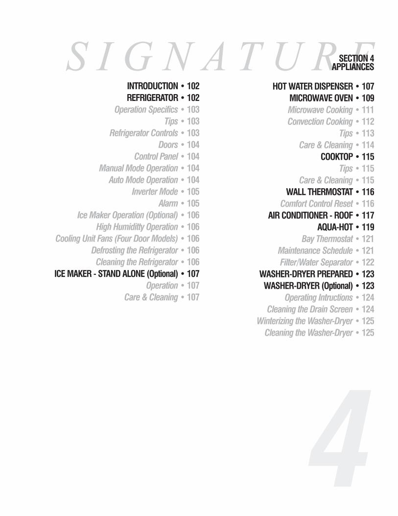
S I G N A T U R ESECTION 4APPLIANCES
INTRODUCTION • 102REFRIGERATOR • 102
Operation Specifics • 103Tips • 103
Refrigerator Controls • 103Doors • 104
Control Panel • 104Manual Mode Operation • 104
Auto Mode Operation • 104Inverter Mode • 105
Alarm • 105Ice Maker Operation (Optional) • 106
High Humiditty Operation • 106Cooling Unit Fans (Four Door Models) • 106
Defrosting the Refrigerator • 106Cleaning the Refrigerator • 106
ICE MAKER - STAND ALONE (Optional) • 107Operation • 107
Care & Cleaning • 107
4
HOT WATER DISPENSER • 107MICROWAVE OVEN • 109Microwave Cooking • 111Convection Cooking • 112
Tips • 113Care & Cleaning • 114
COOKTOP • 115Tips • 115
Care & Cleaning • 115WALL THERMOSTAT • 116
Comfort Control Reset • 116AIR CONDITIONER - ROOF • 117
AQUA-HOT • 119 Bay Thermostat • 121
Maintenance Schedule • 121Filter/Water Separator • 122
WASHER-DRYER PREPARED • 123 WASHER-DRYER (Optional) • 123
Operating Intructions • 124Cleaning the Drain Screen • 124
Winterizing the Washer-Dryer • 125 Cleaning the Washer-Dryer • 125


This section covers operation and care of various appliances found in themotorhome. The motorhome is equipped with a refrigerator, cooktop,microwave, furnace, water heater, roof air conditioner and several optionalappliances. Many of these appliances operate on AC or DC current, LP-Gas ora combination of all three.
Detailed information with CAUTION or WARNINGinstructions for the various appliances, other than what isfound in this section, can be found in the manufacturer’smanual.
WARNING: Before entering any type of refueling stationmake sure all LP-Gas operated appliances are off. Most LP-Gas appliances used in recreational vehicles are vented tothe outside. When parked close to a gasoline pump it is possible for fuel vapors to enter this type of appliance andignite, resulting in an explosion or fire. Carbon monoxide gasmay cause nausea, fainting or death. Operating an LP-Gasappliance with inadequate ventilation or partial blockage ofthe flue can result in carbon monoxide poisoning. Do notstore flammable liquids such as lighter fluid, gasoline orpropane in the outside refrigerator compartment.
The refrigerator in the motorhome operates on a different principle than astandard household refrigerator. Knowing these differences should answerquestions or solve problems that may arise. A standard household refrigeratoruses a different type of refrigerant. A compressor will pump refrigerant vaporinto a condenser where the heat from the refrigerant will be dissipated and thevapor will change to a liquid. The liquid refrigerant is pumped through ametered orifice or capillary tube at the evaporator. At this time the refrigerantchanges from liquid to a vapor. This change cools the evaporator. Air is thenblown across the evaporator and into the interior of the refrigerator. This sys-tem is efficient as long as 120 Volts AC is available; however, this does notallow the freedom a recreational vehicle is designed to give. The recreationalvehicle refrigerator uses a combination of fluids and gas for refrigeration:ammonia, water, sodium chromate and hydrogen gas. This combination is putinto a pressurized cooling unit at approximately 350 psi. It is heated to agaseous state which then rises to the top of the cooling unit into a condenserwhere it forms droplets as it cools. As the vapor condenses it will “extract orabsorb” heat from the inside of the refrigerator. Using gravity, the dropletsreturn through the absorber coils to the absorber vessel to start the processagain. The cooling unit has specific guidelines that need to be followed forproper operation and insured longevity. Keeping these guidelines in mindshould give years of faithful troublefree service.
Appliances------------------------------------------------------------------------------------------------------------------------------------------------------------------------------------------------------------------------------------------------------------------------------------------------------------------
S I G N AT U R E 4 • 1 0 2
REFRIGERATOR
INTRODUCTION

Appliances---------------------------------------------------------------------------------------------------------------------------------------------------------------------------------------------------------------------------------------------------------------------------------------------------------------------
S I G N AT U R E4 • 1 0 3
The refrigerator operates from either LP-Gas or 120 Volts AC electric. Controlsare electronic which require the DC Voltage to be no higher than 15.4 Volts DC orlower than 10.5 Volts DC. The AC voltage limits are 132 Volts AC maximum and108 Volts AC minimum. The refrigerator (from front view) needs to be leveledwithin 3º side to side and 6º front to back. Using a torpedo or bulls eye (fence post)level, place the level onto the freezer plate. The level should be within the circle bya half of a bubble. Generally, this is within comfortable living conditions. The heatsource for the cooling unit is supplied by an electric heating element, or an LP-Gasflame. The heat source, which is calibrated in BTU’s (British Thermal Units), isconcentrated to a specific area of the cooling unit. Operating the refrigerator in an“off level” condition separates the sodium chromate which will crystallize from theheat source. This blocks the recirculation action of the cooling unit and causes accu-mulative, irreparable damage. It is safe to operate the refrigerator while driving themotorhome because the chemicals are in a constant state of agitation from themovement and will not be at risk for seperation. The LP-Gas side of the refrigeratorand the LP-Gas pressure need to be serviced yearly, depending on use. Over timethe BTU rating of the LP-Gas can change, affecting the refrigerator’s performance.Ambient air temperature and humidity can also affect its performance and function.The BTU rating is lower when operating on LP-Gas at an altitude higher than 5,500feet. This affects the refrigerator’s performance. If possible, switch mode operationto 120 Volts AC electric while at a higher altitude.
WARNING: Do not use the refrigerator if there is an ammonia smellinside or outside of the refrigerator, or if a yellowish substance appearsinside the box or in the outside access compartment. This can be an indi-cation of a refrigerant leak. Contact an authorized repair facility.
• If possible, cool items first before putting them into the refrigerator.• Keep the doors shut. Think about what you want before opening the doors.• Allow the refrigerator 24 hours of operation before actual use to help it get
a “head start” with the refrigeration process.• A box of open baking soda will help absorb food odors. Wipe up any
spilled soda.
The refrigerator controls are DC (direct current) operated through an electroniccircuit board. The refrigerator, which operates from heat (as described previously),gets its heat source two different ways: an electric heating element or a flame fromLP-Gas. Mode operation and temperature selection is made by controls on the faceof the refrigerator. In order for the refrigerator to operate the house batteries mustbe charged, the LP-Gas valve on, the water valve on (ice maker option only) andthe refrigerator AC cord plugged in (located in outside refrigerator access door). Ifthe controls do not light up check the house batteries charge status or see if the 12Volt wires are plugged into the refrigerator’s circuit board (outside in refrigeratoraccess door).
OperationSpecifics
Tips
RefrigeratorControls

The refrigerator doors are positive lock style doors that close with a “click”to prevent accidental door opening while traveling. When storing themotorhome, the refrigerator doors have a storage position that locks the doorspartially open. This will help reduce odor from mold and bacteria build-up. Acompletely closed up refrigerator in storage is a perfect habitat for molds andbacteria to grow. To use the storage feature open doors approximately halfwayand slide the latch into the cut-out of the strike plate.
ON/OFF Button - Press this button to turn the refrigeratorON. Press and hold this button to turn the refrigerator OFF.LED Display - This screen is used for fault code display.MODE Button - Press and hold this button to cycle therefrigerator through the different modes available: AUTO,AC and LP modes. Release the button when the desiredmode is displayed.TEMP SET Button - Press and hold the button to selectthe desired temperature setting. Five settings are available,from COLD to COLDEST.
This mode will lock the refrigerator into either LP-Gas or electric AC oper-ation. Press and hold the MODE button until LP or AC is displayed. Releasewhen the desired function is lit. The Alarm will sound and a code will be dis-played if the function selected is interrupted or a failure occurs. Note the codeand turn the refrigerator off to silence the alarm. Refer to the manufacturer’smanual for a list of codes and their meanings.
This feature will automatically select 120 Volts AC over LP-Gas operation.If 120 Volts AC is available it will use this source for operation until AC service has been discontinued. When AC is discontinued the alarm will soundand the refrigerator will automatically switch to LP-Gas operation. If the refrigerator fails to light the alarm will sound and a code will be displayed.
Press and hold the MODE button until AUTO is displayed, release the button. Press and hold the TEMP SET button until desired temperature is displayed, release button. In AUTO mode, AC or LP will remain lit for 10 seconds upon initial start or when mode has changed.
Appliances------------------------------------------------------------------------------------------------------------------------------------------------------------------------------------------------------------------------------------------------------------------------------------------------------------------
S I G N AT U R E 4 • 1 0 4
Doors
Control Panel
NORCOLD COLD COLDEST
AUTO AC LP
ON/OFF TEMPSET MODE Sr
The Refrigerator Control Panel requires 12 Volt DC to operate.
Manual ModeOperation
Auto ModeOperation

Appliances---------------------------------------------------------------------------------------------------------------------------------------------------------------------------------------------------------------------------------------------------------------------------------------------------------------------
S I G N AT U R E4 • 1 0 5
While traveling, the refrigerator may be operated using the 120 Volt AC electricmode to keep the refrigerator contents cool. The electrical combination of theengine’s alternator and the inverter will supply the power necessary to operate therefrigerator on 120 Volts AC. Operating the refrigerator on LP-Gas when refuelingcan be dangerous. Use the AC electric mode when in travel to avoid this situation.Disable this feature when the engine is turned off. House battery power is quicklyconsumed when using the inverter to operate the refrigerator on AC electric. Hookto shore power, start the generator or switch refrigerator operation to LP Gas. Turnthe inverter off when not in use.
To enable this feature:1. Turn the inverter ON.2. Turn the refrigerator ON. Select AC power operation.
To disable this feature:1. Turn the inverter OFF.2. Hook to shore power, start the generator or switch operation to LP-
Gas.
Note: Use this feature only when the engine is running. Failure to disable thisfeature with the engine off will result in dead house batteries. Hook to shorepower, start the generator or switch refrigerator operation to LP-Gas.
The refrigerator uses an audible alarm that will sound for the following rea-sons:
1. DC or AC voltage is higher or lower than allowed specifications.2. Refrigerator is set to auto mode and the 120 Volts AC is discontin-
ued.3. Liquid Petroleum Gas mode fails to light initially or fails to light
after a period of operation.4. Door has been left open longer than two minutes.5. The circuit board detects a failure resulting in a code being dis-
played.
NOTE: If the alarm sounds, note the code in the LED display and turnthe refrigerator off to silence the alarm. Refer to the manufacturer’smanual for the list of codes and their meanings.
NOTE: Keep the interior box temperature at or below 54º F to reducethe possibility of food spoilage. The refrigerator works harder to keep alow box temperature, especially in hot, humid climates. Low box tem-perature may also add quicker frost build-up.
WARNING: Make sure all flames are extinguished and the LP-Gasvalve is off before refueling. LP-Gas and gasoline are highly flammablewhich can ignite, resulting in an explosion, fire or death. Many stateshave passed laws regarding having the LP-Gas valve open while travel-ing. Know the laws for the particular state in which you are traveling.
Inverter ModeOperation
Alarm

Appliances------------------------------------------------------------------------------------------------------------------------------------------------------------------------------------------------------------------------------------------------------------------------------------------------------------------
S I G N AT U R E 4 • 1 0 6
The ice maker works from 120 Volts AC only. The ice maker will start tofunction only after the freezer temperature is low enough. City water or thewater pump must be on and the valve (located in vanity cabinet) for thewater supply line to the ice maker must be on. Pulling the metal arm (bail)down will turn the ice maker on. Pushing the arm up will turn the ice makeroff.
If the ice maker is in operation while the motorhome is in motion, watermay spill out of the ice tray. Raise the ice maker arm to stop ice produc-tion while the motorhome is in transit.
NOTE: Do not use the first one or two trays of ice if the refrigera-tor has been in storage. Ice cubes may have contaminates. Do notoperate the ice maker without water pressure supplied to therefrigerator. This can cause damage to the ice maker assembly.
The refrigerator is equipped with a heating element located in the flapper on the left door (four door model) or in the door (two door model). The heat-ing element is activated when the refrigerator is turned on to any mode tohelp prevent moisture build-up in high humidity conditions.
The cooling unit is equipped with a pair of cooling fans to help pass airacross the cooling unit. These fans start automatically and will be audiblewhen in operation.
Turn the refrigerator off and remove all items. Leave the drip tray underthe cooling fins. Do not use heating guns, hair dryer or sharp objects toremove frost build-up as these can damage the interior. Leave all doors open.Defrost time can be shortened using trays of warm water. Wipe off excesswater using paper towels or cotton cloth.
Wipe using only cotton or paper towels. Products such as FORMULA409, DAWN and FANTASTIK are acceptable cleaners. Do not use scouringpads or abrasive cleanser as these can damage the interior finish.
Cooling Unit Fans(four door models)
High HumidityOperation
Ice MakerOperation(Optional)
Cleaningthe Refrigerator
Defrosting the Refrigerator
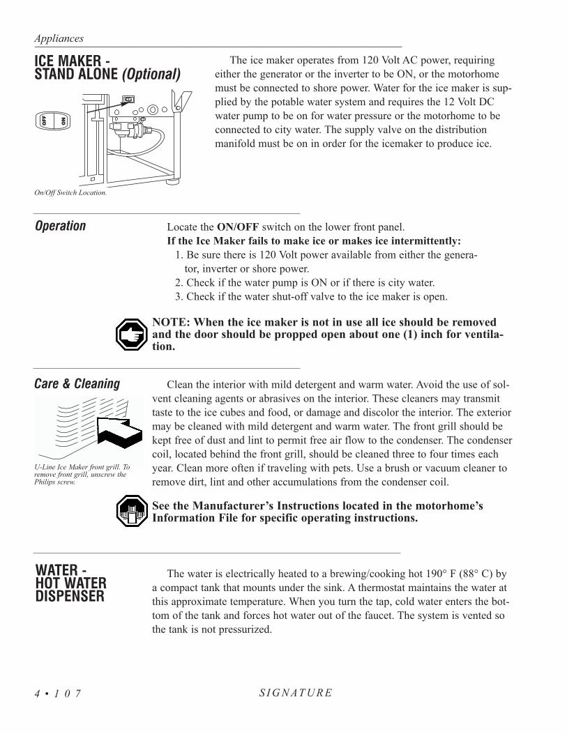
Appliances---------------------------------------------------------------------------------------------------------------------------------------------------------------------------------------------------------------------------------------------------------------------------------------------------------------------
S I G N AT U R E4 • 1 0 7
The ice maker operates from 120 Volt AC power, requiringeither the generator or the inverter to be ON, or the motorhomemust be connected to shore power. Water for the ice maker is sup-plied by the potable water system and requires the 12 Volt DCwater pump to be on for water pressure or the motorhome to beconnected to city water. The supply valve on the distributionmanifold must be on in order for the icemaker to produce ice.
Locate the ON/OFF switch on the lower front panel.If the Ice Maker fails to make ice or makes ice intermittently:
1. Be sure there is 120 Volt power available from either the genera-tor, inverter or shore power.
2. Check if the water pump is ON or if there is city water.3. Check if the water shut-off valve to the ice maker is open.
NOTE: When the ice maker is not in use all ice should be removedand the door should be propped open about one (1) inch for ventila-tion.
Clean the interior with mild detergent and warm water. Avoid the use of sol-vent cleaning agents or abrasives on the interior. These cleaners may transmittaste to the ice cubes and food, or damage and discolor the interior. The exteriormay be cleaned with mild detergent and warm water. The front grill should bekept free of dust and lint to permit free air flow to the condenser. The condensercoil, located behind the front grill, should be cleaned three to four times eachyear. Clean more often if traveling with pets. Use a brush or vacuum cleaner toremove dirt, lint and other accumulations from the condenser coil.
See the Manufacturer’s Instructions located in the motorhome’sInformation File for specific operating instructions.
The water is electrically heated to a brewing/cooking hot 190° F (88° C) bya compact tank that mounts under the sink. A thermostat maintains the water atthis approximate temperature. When you turn the tap, cold water enters the bot-tom of the tank and forces hot water out of the faucet. The system is vented sothe tank is not pressurized.
Operation
Care & Cleaning
U-Line Ice Maker front grill. Toremove front grill, unscrew thePhilips screw.
ICE MAKER - STAND ALONE (Optional)
On/Off Switch Location.
WATER - HOT WATERDISPENSER

Appliances------------------------------------------------------------------------------------------------------------------------------------------------------------------------------------------------------------------------------------------------------------------------------------------------------------------
S I G N AT U R E 4 • 1 0 8
OperationTurn the insta-hot switch, located in the galley, to the ON
position. It will take 10 to 15 minutes for water to reach 190°F (88° C) in temperature. Steam or hot water may come out ofthe faucet without turning it on. After 10 to 15 minutes turn onthe faucet for about 20 seconds to bleed off any steam untilthe hot water is dispersed. Allow the water in the tank toreheat. Repeat this step one or two times. When hot waterwith no steam is dispensed, turn the faucet on to use hotwater. To shut off the system, turn the galley switch to theOFF position.
Temperature AdjustmentIf the steam cannot be stopped, or the water boils, adjust temperature as follows:
• Turn the galley switch off and unplug the power cord.• Remove the screw and access cover.• Insert a screwdriver in the slot of the thermostat adjust-
ing screw and turn clockwise a 1/2 notch to increasethe water temperature, or counterclockwise a 1/2 notchto decrease the water temperature.
• Reinstall the access cover, reconnect the electric powerand turn on the galley switch.
• Draw three or four cups of water and allow unit to reheat.• Repeat the procedure until desired temperature is reached. DO NOT ALLOW THE WATER TO BOIL.
Cleaning Hot Water DispenserUse only mild cleaners to clean the dispenser spout and plas-
tic components. Use of cleaning agents containing acids, alkaliesand organic solvents will result in the deterioration of plasticcomponents.
WARNING: Use care when operating this unit. Do not allow childrento operate this unit. The tank is a non-pressure tank, DO NOT modi-fy this system. DO NOT close the vent tube or connect other types offaucets or valves to the tank. Use only the faucet supplied. DO NOTallow the water to boil. The water and steam dispensed can instantlycause scalds or boils. To minimize the possibility of fire DO NOTstore flammable items such as rags, paper or aerosol cans near thetank. DO NOT store or use gasoline or other flammable vapors andliquids in the vicinity of this unit. DO NOT remove or alter the ther-mal safety fuse. If the thermal fuse is open contact your authorizedservice center. To prevent electrical shock turn the power switch OFFand disconnect the power cord before removing the access cover toadjust or service the thermostat.

The microwave oven is operated from 120 Volt AC supplied by either shorepower, the generator or the inverter. Microwaves heat food by using soundwaves generated at a very high frequency (2,450 MHZ) to agitate the watermolecules inside the item being heated. The higher the water content is to solidsthe faster the response or the shorter the cooking time. Inside the microwave isa turntable that rotates when the microwave is operating. This helps to heat thefood evenly. The turntable can be turned off if a baking dish or other large itemis used. The microwave is designed to sit over a range or cooktop. When cook-ing from the cooktop, use the microwave’s two speed ventilation fan. The fan draws air in from the bottom of the microwave througha pair of grease filters then discharges the filtered air out through a replacablecharcoal filter at the top. The ventilation fan may be operated manually or maystart automatically by a thermostat activated from heat produced by the cook-top.
The microwave offers many different features. Some include varied cookingtimes with different power settings: automatic sensor cooking, a kitchen timer,Metric to American conversion chart (which includes temperature and weight),on screen programming help, childproof lockout and auto defrost cycles. Thescreen may be programmed to display one of three different languages.
The microwave/convection oven has the ability to cook food with heat likean electric oven, or preheat the oven with heat and cook with microwaves.Other features include the ability to cook with microwaves and convection atthe same time, sensor cooking and a built-in broiler.
WARNING: If a fire flares up when using the cooktop, turn off theventilation fan. The fan may spread the flame. If the ventilation fanhas started automatically from a heated cooktop it can not be manu-ally turned off. Turn off the microwave AC circuit breaker or unplugthe unit to prevent the flame from getting up into the microwave andspreading the fire.
NOTE: When cooking in convection mode try to avoid using theinverter as the AC power source due to the high rate of battery consumption.
NOTE: The microwave is for food preparation only. Do not use themicrowave to dry clothes, newspapers, shoes or other items.
Safety Lock:The microwave comes with a safety lock feature. This feature prevents the
oven from operating accidentally. To use this feature:• Press the CUSTOM HELP pad. • Press the 1 pad. • Press the START/TOUCH-ON pad.
The oven is now locked. If any button is pressed the word LOCK appearson the screen and the oven will not operate. The fan and hood light are still
Appliances---------------------------------------------------------------------------------------------------------------------------------------------------------------------------------------------------------------------------------------------------------------------------------------------------------------------
S I G N AT U R E4 • 1 0 9
MICROWAVE OVEN

Appliances------------------------------------------------------------------------------------------------------------------------------------------------------------------------------------------------------------------------------------------------------------------------------------------------------------------
S I G N AT U R E 4 • 1 1 0
operational with the Safety Lock feature on. To return the oven to normal operation:• Press the CUSTOM HELP pad. • Press the 1 pad.• Press the START/TOUCH-ON pad. The oven will resume normal
operation.
Setting The Clock:• Press the STOP/CLEAR pad.• Press the CLOCK pad. • Enter the time in sequence using the number pads.• Press the CLOCK pad to begin time.
NOTE: The clock is a 12 hour clock only. When AC power is discontin-ued the clock time will be erased.
Kitchen Timer:• Press the KITCHEN TIMER pad. • Using the number pads enter minutes and seconds, or 00 if no seconds. • Press the START/TOUCH-ON pad to begin timer. Timer end will be
signaled by one long beep.
Press the STOP/CLEAR pad to:• Erase, if you make a mistake during programming.• Cancel the kitchen timer.• Stop the oven temporarily during cooking.
(Press the START/TOUCH-ON pad to resume.)• Return the time of day to the display.• Cancel a program during cooking (touch the pad twice).
Turntable On/Off:• Press TURNTABLE ON/OFF pad to stop or start the turntable.• Enter the cook time desired minutes and seconds.• Enter power level desired.• Press the START/TOUCH-ON pad.
Hood Light: To turn the hood light on or off touch the LIGHT button.
Ventilation Fan:Press the FAN HI/LO button once for high, twice for low and three times for off.
Microwave - Timed Cooking:The maximum amount of cooking time is 99 minutes and 99 seconds. Be sure to enter minutes and seconds. If seconds are not desired, enter 00.

Appliances---------------------------------------------------------------------------------------------------------------------------------------------------------------------------------------------------------------------------------------------------------------------------------------------------------------------
S I G N AT U R E4 • 1 1 1
Press and hold the START/TOUCH-ON. The microwave pad operates at100% power until the pad is released. This mode can be used for up to threeminutes and up to three consecutive cycles.
One Minute Cook Times:Press the MINUTE PLUS pad if one minute at full power is desired or to
add one minute intervals to cooking time. The MINUTE PLUS pad must bepressed within one minute of closing the door, or during selected cooking time.For safety, the minute plus feature will lockout if there is no microwave activity within one minute of closing the door. Use the START/TOUCH-ONpad to reset the one minute safety period.
Microwave Settings:To use 100% power, enter cook time by pressing the number pads. Press the
START/TOUCH-ON pad to begin cook timeTo use settings lower than 100% power, use the number pads to enter
desired cooking time. Press the POWER LEVEL pad. Use the number pad to select desired power level. Press the START/TOUCH-ON pad to begin cook time
Multiple Sequence Cooking:If sequential cooking times with varied power levels are desired, press the
POWER LEVEL pad and select desired power level. Use the number pad toenter cook time for the first interval. Press POWER LEVEL pad again, selectdesired power level, then enter cook time for the next time period. Press theSTART/TOUCH-ON pad to begin sequential cooking. The microwave can holdup to four sequential cook time periods. If full power is desired in any of thetime periods, skip the power level step. 100% power will be automaticallyselected.
Keep Warm:Press the KEEP WARM pad during cooking time to automatically keep
food warm for up to 30 minutes after cooking time has expired. To use this fea-ture after cooking time has expired, or after the food has been removed andreheating is desired, place the food back into oven and press the KEEP WARMpad.
Defrosting can be done on manual time selection or use the microwave’sCompuDefrost.
Manual Defrost:Press the POWER LEVEL pad. Select number 3 for defrost power. Enter
desired defrost time. Be sure to stir or break food apart at regular intervals.
Microwave Cooking

Appliances------------------------------------------------------------------------------------------------------------------------------------------------------------------------------------------------------------------------------------------------------------------------------------------------------------------
S I G N AT U R E 4 • 1 1 2
CompuDefrost:The microwave has automated defrost programs for different foods and
weights. Press the COMPUDEFROST pad to enter this mode. PressCOMPUDEFROST again to select between ground meat, steak or chicken.Use number pads to enter weight of food being defrosted. PressSTART/TOUCH-ON to begin defrost cycle
Sensor Cooking:The microwave has electronic sensors that sense moisture or humidity
given off by the food during the cooking process. Electronic sensors will beaffected if room temperature exceeds 95° F. To adjust the sensor cookingmode to allow for more or less cooking time, press the SENSOR COOKpad. Press the POWER LEVEL pad once to increase cooking time or twiceto decrease cook time.
To use the sensor cooking mode, press the SENSOR COOK pad. Selectthe number or food desired from the library listed adjacent to the SENSORCOOK pad. Press the START/TOUCH-ON pad to begin sensor cooking.
The interior of the microwave produces heat just as it does in a regularoven. The convection cooking mode has special options such as a broil mode,plus the ability to preheat oven by convection and use microwaves to com-plete cooking or to preheat.
NOTE: When using the convection oven feature leave the turntablein place and do not restrict the rotation. This can damage themicrowave.
Cooking with Convection:Press the CONVEC pad. Press the numbered pad with the desired cook-
ing temperature. Press the numbered pads for desired cooking time. Press theSTART/TOUCH-ON pad to begin convection cooking.
Manual Broiling:The Manual Broiling temperature is automatically preset to 450° F. Only
the cooking time can be adjusted.To use the broiler, press the BROIL pad. Enter amount of cooking time.
Press the START/TOUCH-ON pad to begin preheating the oven. Four beepswill signal the end of the preheat cycle. Food can now be placed into theoven.
CompuBroil:The CompuBroil cooking method has programs preset for common foods
like hamburger, steak, chicken and fish. Temperature and time are presetdepending on the food quantity. The amount of cooking time can be adjusted
Convection Cooking

Appliances---------------------------------------------------------------------------------------------------------------------------------------------------------------------------------------------------------------------------------------------------------------------------------------------------------------------
S I G N AT U R E4 • 1 1 3
to fit any particular need. The POWER LEVEL pad will vary the preset cook-ing time. Press once for more time and twice for less time.
To use the CompuBroil feature press the COMPUBROIL pad. Select thefood number from the food library next to the CompuBroil pad. Enter the num-ber of pieces being broiled. Press the START/TOUCH-ON pad to begin thepreheat cycle. A series of four beeps signal the end of preheat cycle.
Automatic Mix Cooking:This method combines both the convection oven and microwave at the same
time. While in this mode the microwave will use 30% power on HIGH/MIXand 10% power on LO/MIX. The convection temperature can be changed from100 to 450° F. The default convection temperature is 325° F for bothHIGH/MIX and LO/MIX.
To use this feature select either HIGH/MIX or LOW/MIX. Use the number pads to enter cooking time. Press the START/TOUCH-ON pad tobegin the mixed cooking cycle.
CompuRoast or CompuBake:CompuRoast and CompuBake can be used for food items ranging from
pastries and cakes to roasts, chicken and pork. The temperature is preset forboth functions. Only the cook times can be tailored for individual preference byentering into either the CompuRoast or the CompuBake mode. Press thePOWER LEVEL pad once for more cooking time and twice for less cooking time. To use either function, press the desired pad and enter the foodtype from list next to the mode used. Enter the food type being cooked by usingthe number pad. To use CompuBake, press the START/TOUCH-ON pad tobegin preheat cycle. To use CompuRoast, enter the weight of item using thenumber pads. Press the START/TOUCH-ON pad to begin the preheat cycle.Four beeps will signal the end of the preheat cycle and the oven is now ready.
• Check the type of cookware being used to see if it is microwaveor oven safe depending on the type of cooking being done.
• Gold paint or glaze may contain a trace amount of gold which is electrically conductive and not compatible for microwave. Hand-painted china commonly contains traces of metal.• To test utensil for microwave compatibility place it in the
microwave with an 8 oz. plastic cup of water. Set the microwaveat full power for one minute. Carefully feel the utensil. Theentire utensil should be cool to the touch.
• Cover food with a paper towel or upside-down plate to help keepfood spattering to a minimum. Place a paper towel on theturntable to keep clean-up at a minimum. Use paper towelsdesigned for microwave use only.
Tips

Appliances------------------------------------------------------------------------------------------------------------------------------------------------------------------------------------------------------------------------------------------------------------------------------------------------------------------
S I G N AT U R E 4 • 1 1 4
• Clean all spills or spatters before they dry.• Food odors may linger inside oven. To help eliminate odors
combine the juice and the peel from one lemon, several wholecloves and 8 oz. of water into a two cup bowl. Place in ovenon high power, bring to a boil for several minutes. Let cool inthe oven for several minutes.
• Some food wrappers may be foil lined. Check the wrappingcarefully before cooking or heating. Small amounts of foil areacceptable if not wrinkled or near the sides of the microwave.
• If the microwave screen is not lit plug another electrical appli-ance into the same outlet the microwave was plugged in toverify AC power is present. If the test item works, contact anappliance repair facility to have the microwave checked.
The exterior of the oven is plastic and metal. The interior is metal. Do notuse scouring pads, harsh or abrasive cleanser, chemical cleaners or petroleumbased thinners as these can damage the finish. Use mild soap and water witha damp cloth or paper towel to remove most stains or spills. When cleaningthe touch pad open the door to prevent accidental operation. Use mild soapand water with a soft cloth. Avoid using excess amounts of water on thetouch pad. The turntable plate and oven racks are dishwasher safe.
Grease Filters:Do not operate the oven without the grease filters in place. This can dam-
age the microwave. Grease filters should be cleaned at least once a month.To remove the filters, use the pull tab to slide the filter to the end of theopening and tip down. Soak the filters in the sink or in a dishpan filled withhot water and detergent.
• Do not use ammonia or other alkali based products. They may darken the filter material.
• Agitate the filter. Use a scrub brush to remove caked on grease. • Rinse the filter thoroughly and shake it dry. Place the filter back into the
opening, tip it upward and slide it to the end of the opening. Lock it in place. Be careful not to kink or warp the filter upon installation.
Care & Cleaning

Appliances---------------------------------------------------------------------------------------------------------------------------------------------------------------------------------------------------------------------------------------------------------------------------------------------------------------------
S I G N AT U R E4 • 1 1 5
Cooktop burners use 110 Volt AC electronic ignition to light the burners. To supplycurrent to the cook top turn the inverter on, hook to shore power or start the generator.
To conserve energy preheat the pans only when recommended and shorten thecooking time by using the least amount of water possible. Do not let the flame extendbeyond the cooking utensil. When cooking, heat the food on a higher heat setting thenturn the heat down to finish cooking.
To Light the Burners:1. Make sure the LP-Gas is turned on.2. Push down the knob and turn it counterclockwise to the ignite position.3. Hold the knob down fully until the spark ignites the gas and until the
thermocouple is heated (approximately 5 to 10 seconds). This will acti-vate the safety magnet and keep the burner lit.
4. Release the knob and set the flame to the desired setting.5. Turn the knob clockwise to turn it off.
NOTE: All electric cook tops require burners to be heated 3-5 seconds before use.
• Allow extra cooking time while at a higher altitude.• Yellow flame or tips indicate an improper air to fuel ratio in the fuel or
that the burner port needs cleaning.• Large burner is 12,500 BTU’s. Small burner is 6,000 BTU’s.
LP - Gas Cooktop• Use a dry cloth or paper towel to clean spatters and spills while the sur-
face is still warm.• Regular cleaning with a soft cloth and a warm detergent solution is
generally enough to keep the cooktop clean. This should be done whenthe cook top is cool.
• Wipe stainless steel surfaces in direction of grain.• Avoid using oven cleaners or chlorine based cleaners.• Clean burner caps with soap and water.• If burner port is clogged remove the cap. Use a straight pin to clean
burner ports. Do not damage or modify burner ports.
Electric Cooktop• Wipe up spills and spatters immediately using damp cloth. • Use a razor blade to scrape dried surface spills. • Heavy duty cleansing powders will scratch cooktop surface. “Hope’s
Cooktop Cleaning Cream” may be used on the cook top surface . Tocontact the Hope Co. call (800) 325-4026.
NOTE: All electric coaches require the appliance selector switch to be in the cooktop position for operation.
COOKTOP
Tips
Care &Cleaning

Appliances------------------------------------------------------------------------------------------------------------------------------------------------------------------------------------------------------------------------------------------------------------------------------------------------------------------
S I G N AT U R E 4 • 1 1 6
Two comfort controls are used for the HVAC (heating, ventilatingand air conditioning) system. One comfort control is located in the livingroom. The living room comfort control will operate the front roof airconditioner functions and the LP-Gas furnace operation. If themotorhome is equipped with an Aqua-Hot, the living room comfort con-trol will operate the dinette and living room heat exchangers.
The other comfort control is located in the bedroom. The bedroomcomfort control will operate the rear roof air conditioner and (ifequipped) the mid roof air conditioner functions. If the motorhome isequipped with an Aqua-Hot, the bedroom comfort control will operatethe hallway, bathroom and bedroom heat exchangers. The comfort con-trol uses a liquid crystal display to inform the operator of current modestatus.
Their are six different functions of the HVAC system: Off, Fan, Cool,Heat Pump and Furnace. These may be selected by repeat pressing of theMODE button. The roof air conditioner fan speed is controlled by theFAN button. Three speeds are available: low, medium and high. Fanspeed control applies to the roof air conditioner’s blower speed only. Selectingthe fan speed Auto adjusts the fan speed automatically, depending on tempera-ture set point and actual temperature in a selected zone. The roof air conditionerwill use all three blower speeds (low, medium or high) when Auto fan is selectedin Cool mode. If operating in Heat Pump mode and Auto Fan is selected onlylow or high blower speeds will be used.
The motorhome is divided into three operating Zones: front, middle and rear.The living room comfort control is Zone One, although this is not displayed. Thebedroom comfort control operates the middle area, which is displayed as ZoneTwo. The bedroom area is considered Zone Three; however, it is displayed asZone One on the bedroom comfort control. Zone selection is made by pressingthe MODE and FAN buttons simultaneously. The temperature for any HVACfunction is controlled by pressing the UP or DOWN buttons.
NOTE: The Comfort Control must be turned to ON to operate any HVACfunction. Comfort Control modes cannot be mixed. One zone cannot be onCool while another zone is set to Furnace.
NOTE: The motorhome will not heat or cool faster by selecting a very highor very low temperature setting.
Should the comfort control exhibit unusual symptoms or not respond tocommands, it may need to be reset. To reset:
• Press the MODE button. Display backlighting should illuminate. • Press MODE, UP and DOWN buttons simultaneously five to ten
seconds. The comfort control should return to mode OFF. Thefactory default settings of 72° F for Cool and 68° F for Furnaceshould be established.
Comfort ControlReset
WALL THERMOSTAT
MODE OFF
MODE
FAN
TEMP
UP
ONOFF
DOWN
ZONE
ZONE 1
DUO-THERM

Appliances---------------------------------------------------------------------------------------------------------------------------------------------------------------------------------------------------------------------------------------------------------------------------------------------------------------------
S I G N AT U R E4 • 1 1 7
The roof air conditioners operate from 120 Volts AC only, either by shorepower or the generator. Operations are controlled by the12 Volt DC comfortcontrol. The electronics in the comfort control use a telephone type patch cordto send a low voltage signal to the roof air conditioner’s circuit board. The cir-cuit board controls the desired roof air functions and LP-Gas furnace or (ifequipped) Aqua Hot operation. The refrigerant operation principal of the roofair conditioner is the same as the dash air conditioner or a household typerefrigerator. It functions as an enclosed system. The refrigerant is drawn intothe compressor. The high pressure vapor is sent to a condenser where the heat isexpelled into the atmosphere. The vapor leaves the condenser as a high pressureliquid. This liquid is forced into a metered capillary tube and then into the evap-orator or low side pressure. The refrigerant changes from liquid form to vaporas the heat is extracted. The vapor is drawn back into the compressor to startthe cycle again. The air conditioning principal is reversed when operating theroof air conditioner in heat pump mode. The refrigerant flow is reversed blow-ing heated air into the interior of the motorhome. There are ambient tempera-ture limitations of the heat pump mode
NOTE: The air conditioning system will freeze the moisture in the airdepending on the humidity content. Under high humidity conditions it isrecommended to set the blower fan speed to High.
NOTE: The roof air conditioner will not operate in Heat Pump mode withambient temperatures at or below 26º F.
Aux Heat ModeIf the heat pump mode is selected when ambient temperatures are approxi-
mately 26° F, or if operating in Heat Pump mode and temperature drops toapproximately 26º F, the air conditioner will stop Heat Pump operation and AuxHeat operation will begin. The furnace is automatically selected as an auxiliaryheat source and begins operation.The Aux Heat mode is automatically selecteddue to refrigerant characteristics in cold temperatures. The furnace remains theprimary heat source until ambient temperature rises above 42º Fahrenheit.When ambient temperature is between 24-42º Fahrenheit, a defrost cycle is ini-tiated approximately every 40 minutes of compressor operation. The blowermotor will stop for five minutes and Defrost will be displayed. After the defrostcycle Heat Pump operation will resume.
If the motorhome is equipped with an Aqua Hot and the Aux Heat cycle isinitiated the Aqua-Hot will need to be turned ON by using the Aqua Hot controlswitches located in the galley. The living room and dinette heat exchangerblowers will automatically begin operation. Use the bedroom comfort control toselect Zone One or Zone Two heat exchangers.
The return air filters should be cleaned frequently. They are located on themotorhome ceiling inside the air intake vent covers. Never run the air condi-
AIR CONDITIONER -ROOF

Appliances------------------------------------------------------------------------------------------------------------------------------------------------------------------------------------------------------------------------------------------------------------------------------------------------------------------
S I G N AT U R E 4 • 1 1 8
tioner without the return air filters in place as this may plug the evaporator corewith dirt and substantially affect the performance of the air conditioner.
To Clean:• Remove the vent covers and filters.• Wash the filters and covers in warm soapy water. Do not use sol-
vents.• Rinse the filters and cover thoroughly with fresh water and allow
them to dry.• Reinstall the filters and covers.
The roof air conditioner will operate only when the following needshave been met:
• 120 Volts AC from either shore power or the generator is sup-plied.
• The battery cut-off switch is in the ON position and house batter-ies are charged.
Fan Operation:This mode circulates the interior air by using the roof air conditioner blower.
The fan speed will control the roof air conditioner blower speed in the followingmodes: Fan, Cool or Heat Pump.
• Press the mode button repeatedly until FAN is displayed.• Press the FAN button to select the desired fan speed.
Air Conditioner Operation:The living room comfort control will operate the front roof air condi-
tioner functions. • Press the MODE button repeatedly until Cool is displayed. • Set desired fan speed by pressing the FAN button. • Set desired cooling temperature by pressing the UP or DOWN
buttons.
The Bedroom comfort control will operate the rear roof air condition-er functions and (if equipped) the center roof air conditioner.
• Press the MODE button repeatedly until Cool is displayed. • Pressing the Zone button to alternate between Zone One and Zone
Two. Zone One will control the bedroom roof air conditioer andZone Two will control the center roof air conditioner.
• Set desired fan speed by pressing the FAN button. • Set desired cooling temperature by pressing the UP or DOWN but-
tons.
NOTE: The compressor will engage approximately two minutes after blowermotor activation. This prevents accidental compressor activation against highpressure.
MODE OFF
MODE
FAN
TEMP
UP
ONOFF
DOWN
ZONE
ZONE 1
DUO-THERM
MODE OFF
MODE
FAN
TEMP
UP
ONOFF
DOWN
ZONE
ZONE 1
DUO-THERM
Fan
Cool

Heat Pump Operation:Living room comfort control will operate the front roof air conditioner. • Press the MODE button repeatedly until Heat Pump is dis-
played. • Set desired fan speed by pressing the FAN button. • Set desired heating temperature by pressing the UP or DOWN
buttons.
The bedroom comfort control will operate the rear roof air condition-er and (if equipped) the center roof air conditioner. • Press the MODE button repeatedly until Heat Pump is dis-
played. • Pressing the Zone button to alternate between Zone One and
Zone Two. Zone One will control the bedroom roof air condi-tioner and Zone Two will control the center roof air conditioner.
• Set desired fan speed by pressing the FAN button. • Set desired heating temperature by pressing the UP or DOWN
buttons.
The Aqua-Hot heat system is specially designed for use in motorhomes. TheAqua-Hot is an appliance combining a water heater with a furnace. The Aqua-Hot will provide an almost endless supply of hot water and heat the interior ofthe motorhome. A 50,000 BTU diesel fired burner and a 1,650 watt AC elementheats a 50/50 antifreeze solution to approximately 200º F. The antifreeze solu-tion is pumped through heat exchangers located throughout the motorhome.Four pumps are used to circulate the antifreeze solution. Three pumps supplythe solution to the interior heat exchangers. The fourth pump circulates theantifreeze solution through the engine. Fresh water is heated when pumpedthrough a coil tube inside the aqua hot.
Chlorine bleach or other concentrated chlorine bearing chemicals can causefailure to the Aqua-Hot’s Domestic Water Loop (copper tubing) if not properlyand thoroughly rinsed. The Aqua-Hot’s copper tubing is rated for use with freshwater and winterization solutions only. Periodic flushing with common house-hold chemicals, including bleach, has little or no effect on the heating system ifproperly rinsed with the fresh water afterwards. Failure of copper tubing, espe-cially soft or flexible copper, can result if materials other than water or winteri-zation solutions are allowed to reside inside the piping for extended periods asduring storage or other periods of non-use. The most common cause for failureis due to an extended exposure to chlorine, solutions containing chlorine (i.e.bleach) or hydrochloric acid.
NOTE: The Aqua Hot must be turned ON before using any heat feature.
Appliances---------------------------------------------------------------------------------------------------------------------------------------------------------------------------------------------------------------------------------------------------------------------------------------------------------------------
S I G N AT U R E4 • 1 1 9
AQUA HOT
MODE OFF
MODE
FAN
TEMP
UP
ONOFF
DOWN
ZONE
ZONE 1
DUO-THERM
Heat Pump

Diesel BurnerThe diesel burner will consume approximately ½ gallon of diesel for each
hour of continuous burner operation. The diesel burner is rated at 12 Volt/65watts. Three circulating pumps are rated at 12 Volt/12 watts each. The dieselfired burner has a fast recovery rate. To heat the Aqua-Hot from the dieselburner turn the switch to the ON position. The switch will illuminate when theAqua-Hot is ON. Allow 20-30 minutes for the Aqua-Hot to reach operatingtemperature before operating heat exchangers or using hot water.
Electric Heat ElementThe electric element works well if plugged into 50 amp service. If the
motorhome is plugged into less than 50 amp service, exercise care so the elec-tric service provided will not be overloaded. Electric operation recovery rate isslower than the diesel burner. When the switch is turned on a relay will sendpower from the 110 Volt AC panel to the electric element in the Aqua-Hot.Allow two to three hours for the Aqua-Hot to reach operating temperaturewhen operating from the electric element.
Engine Heat Exchange SystemThe Aqua Hot system has an engine preheat feature to aid in starting in cold
or frigid weather. Located inside the Aqua Hot are a separate engine coolantloop and an engine coolant pump. The Aqua Hot will heat the engine coolantand the internal engine pump will circulate the coolant heating the engine.When traveling, the water pump (on the engine) circulates the heated enginecoolant through the Aqua Hot. Through convection, the heat will be transferredto the Aqua Hot coolant, providing hot water and interior heating.
Engine PreheatTurn the diesel switch to the ON position. The diesel burner will light. Turn
the Engine Preheat to the ON position. This activates the engine pump circulat-ing coolant from the Aqua-Hot through the engine.
Interior Heat ExchangersThe heat exchangers are small radiators with 12 Volt DC blower motors.
Current consumption is approximately .25 watt per large heat exchanger. Thesmall heat exchanger used in the private bath and for the holding tank bay is.10 watt.
NOTE: The HVAC (heating, ventilating, air conditioning) system will not operate correctly when both comfort controls and all zonesare not in the same mode. DO NOT set control to display furnace in onezone and cool displayed in another zone.
Appliances------------------------------------------------------------------------------------------------------------------------------------------------------------------------------------------------------------------------------------------------------------------------------------------------------------------
S I G N AT U R E 4 • 1 2 0

To operate the furnace:• Select either diesel burner or electric element operation.• Turn living room comfort control to ON.• Depress mode button repeatedly until furnace is displayed.• Select desired temperature setting using the up or down but-
tons.
To turn bedroom comfort control to ON:• Depress mode button repeatedly until furnace is displayed.• Depressing the FAN and MODE button simultaneously will
alternate between Zones One and Two. Zone One controls hallway and bathroom exchangers. Zone two operates bedroom exchanger.
• Select desired temperature setting using the up or down but-tons.
NOTE: The blower motor of the heat exchanger in the privatebathroom is controlled by the switch in the private bathroom.When the switch is on, the bathroom blower motor will cycle onand off when the hallway heat exchanger blower motor cycles onor off.
If the motorhome is used in cold weather conditions you will needto locate the bay thermostat next to the Aqua-Hot. This thermostatcontrols the heat exchanger for holding tank bay heat. Adjust thethermostat to 40-50° F. This will help prevent freezing of the watersystem.
NOTE: The Aqua-Hot must be turned ON whenusing the holding tank bay exchanger.
Monthly:Check the Aqua-Hot's 50/50 solution of water and antifreeze to ensure its
proper level. Do this by visually checking coolant level in Aqua-Hot's expansion tank. This should be checked only when the Aqua-Hot is at operatingtemperature. Adding solution to the expansion tank when the unit is cold willresult in a solution overflow when the Aqua-Hot heats to normal operating temperatures.
Annually:Be sure to have the Aqua-Hot tuned up early. A tune up will consist of a fuel
nozzle and fuel filter replacement, as well as a thorough cleaning of the combus-tion chamber. This simple tune up will keep the Aqua-Hot running smoothlythroughout the year, as well as allow service personnel to inspect for additional
Appliances---------------------------------------------------------------------------------------------------------------------------------------------------------------------------------------------------------------------------------------------------------------------------------------------------------------------
S I G N AT U R E4 • 1 2 1
Bay Thermostat
MODE OFF
MODE
FAN
TEMP
UP
ONOFF
DOWN
ZONE
ZONE 1
DUO-THERM
Furnace
MaintenanceSchedule

wear of other components. Signs that the Aqua-Hot may need servicing are:continuous white exhaust smoke or poor ignition start up. When in operationthe Aqua-Hot should have a smooth, high-pitched whine. Loud growls orother abnormal noises indicate service is required.
CAUTION: Before cleaning or servicing disconnect all power sup-plies.
For more details about the Aqua-Hot system see the Owner’sInformation Box.
The filter is on the curb side of motorhome, located behind fuel accessdoor. Remove the two bolts at the bottom of the fuel door and swing the doorupwards. The Aqua-Hot fuel filter/water separator is mounted on top of thechassis frame support.
Draining the Collection Bowl:Water is heavier than fuel and will settle to the bottom of a fuel bowl
which will make it appear different in color. In high humidity environmentscheck the collection bowl more often. With the engine and the Aqua-Hotoff, open the drain to evacuate any contaminants and then close it.
Element Replacement:The contamination levels in the fuel determine the element’s replacement
frequency. Fuel flow to the Aqua-Hot becomes restricted as the element gradually plugs up with contaminates, resulting in noticeable heating lossand/or hard starting. If this occurs, change the element as soon as possible. As a guideline, change the element every 500 hours, annually or at first indication of heat loss, whichever occurs first. Always carry anextra replacement element as one tankful of contaminated fuelcan plug a fuel filter.
To Replace the Element:• Drain the filter unit of fuel by opening drain valve.• Spin bowl/element from head and remove element.• Coat new seals with motor oil and the install new element.• Prime spin bowl/element with clean fuel. • Spin bowl/element onto head and tighten firmly by hand. • Start Aqua-Hot and check for leaks.
Appliances------------------------------------------------------------------------------------------------------------------------------------------------------------------------------------------------------------------------------------------------------------------------------------------------------------------
S I G N AT U R E 4 • 1 2 2
Filter/WaterSeparator
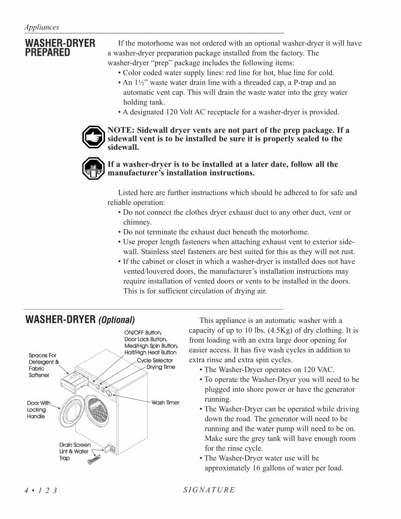
If the motorhome was not ordered with an optional washer-dryer it will havea washer-dryer preparation package installed from the factory. The washer-dryer “prep” package includes the following items:
• Color coded water supply lines: red line for hot, blue line for cold.• An 1½” waste water drain line with a threaded cap, a P-trap and an
automatic vent cap. This will drain the waste water into the grey water holding tank.
• A designated 120 Volt AC receptacle for a washer-dryer is provided.
NOTE: Sidewall dryer vents are not part of the prep package. If asidewall vent is to be installed be sure it is properly sealed to the sidewall.
If a washer-dryer is to be installed at a later date, follow all the manufacturer’s installation instructions.
Listed here are further instructions which should be adhered to for safe and reliable operation:
• Do not connect the clothes dryer exhaust duct to any other duct, vent or chimney.
• Do not terminate the exhaust duct beneath the motorhome.• Use proper length fasteners when attaching exhaust vent to exterior side-
wall. Stainless steel fasteners are best suited for this as they will not rust.• If the cabinet or closet in which a washer-dryer is installed does not have
vented/louvered doors, the manufacturer’s installation instructions may require installation of vented doors or vents to be installed in the doors. This is for sufficient circulation of drying air.
This appliance is an automatic washer with a capacity of up to 10 lbs. (4.5Kg) of dry clothing. It isfront loading with an extra large door opening for easier access. It has five wash cycles in addition toextra rinse and extra spin cycles.
• The Washer-Dryer operates on 120 VAC.• To operate the Washer-Dryer you will need to be
plugged into shore power or have the generator running.
• The Washer-Dryer can be operated while driving down the road. The generator will need to be running and the water pump will need to be on. Make sure the grey tank will have enough room for the rinse cycle.
• The Washer-Dryer water use will be approximately 16 gallons of water per load.
Appliances---------------------------------------------------------------------------------------------------------------------------------------------------------------------------------------------------------------------------------------------------------------------------------------------------------------------
S I G N AT U R E4 • 1 2 3
WASHER-DRYERPREPARED
WASHER-DRYER (Optional)

Before using the washer for the first time, wipe the inside and outsidewith a damp cloth to remove any travel dust that has accumulated. Operatinga rinse cycle to rinse out the washer is recommended. Front load, horizontalaxis washing machines require less detergent. Soap suds line should notexceed the halfway point of the glass door.
To begin a wash load:• Sort and pre-treat clothes.• Add the measured amount of detergent suggested by the package
directions (maximum two tablespoons).• Load the clothes loosely into the washer. Close the washer door.• Turn the cycle selector knob to the desired temperature setting.• Decide which washing cycle you wish to use. Turn the timer knob
clockwise to the desired wash setting.• Select High or Medium spin (only for regular washing).• Press the pushbutton ON.• After the cycle is complete wait two minutes for the door lock to
release before attempting to open the door.
WARNING: Do not wash or dry articles that have previously beencleaned, washed, soaked or spotted with gasoline, dry cleaning sol-vents or other flammable or explosive substances. Do not add thesesubstances to the wash water as they produce vapors that could igniteor explode. Do not use dryer to dry articles containing foam rubberor similar textured, rubber-like materials. Clean the lint screen aftereach use (if applicable), located in the top left corner on the back ofthe washer. Keep the area around the exhaust opening and adjacentareas free from lint, dust and dirt accumulation.
The removable drain screen, which protects the pump from lint andforeign matter, needs to be cleaned periodically. The frequency in whichit is cleaned depends upon the type of clothes that are washed. Cottonarticles produce more lint than nylon articles. Under no circumstanceshould the drain screen be removed while the machine is full of water. Toclean the drain screen, on an empty machine, open the service door bypressing on the left hand side. Place a cloth or shallow tray under thedrain screen housing to catch any remaining water that may drip out. Itmay be helpful to first set the machine to spin, then remove the drainscreen. This procedure reduces the amount of water released. Turn thedrain screen counterclockwise and pull the drain screen out. Clean thescreen to remove any dirt and lint. To replace the screen, slide it backinto the housing and turn it clockwise to secure. Close the service door.
NOTE: Check for water leaks before using the washer afterremoving and replacing the drain screen.
Appliances------------------------------------------------------------------------------------------------------------------------------------------------------------------------------------------------------------------------------------------------------------------------------------------------------------------
S I G N AT U R E 4 • 1 2 4
OperatingInstructions
Cleaning the Drain Screen

To winterize your Washer-Dryer follow the instructions below to avoid freezedamage:
1. With the unit off, remove the wash filter to allow the waterremaining (in the pump and drain hose) to be evacuated. Replacethe filter.
2. Close the inlet shut-off valves located at the manabloc water man-ifold system.
3. Open the low point drains to drain all the water.4. In cold climates, air should be used to blow out the system.5. Install the water pressure regulator on a short water hose. Connect
it to the water system. Use an air hose connector on the female endas this reduces pressure. Make sure one or more faucets are open.Maximum air pressure should not exceed 35 psi.
If antifreeze is being used in the system follow these instructions:1. When putting antifreeze into the water system of your motorhome,
set the washer to a warm/warm fill setting and allow water to flowinto the unit until the antifreeze is detected.
2. Slowly advance the timer to a rinse cycle and allow the water toflow for 10 seconds. Advance the unit to a spin cycle to removethe majority of the water from the unit.
4. With the unit off, remove the wash filter from the unit. This willallow the water remaining in the pump and drain hose to be evacu-ated. Replace the filter.
5. Any water remaining in the unit should contain antifreeze and beprotected from freezing.
NOTE: When placing the unit back into service, allow the unit tooperate for one complete cycle before doing laundry to ensure allantifreeze has been purged from the unit.
As the Washer-Dryer is used, occasionally wipe the exterior of the cabinetwith a damp cloth or sponge. Wipe dry with a soft cloth. Do not use polish onplastic trim. Clean the interior with one cup of chlorine bleach mixed with twocups of granular detergent. Run the washer through a complete cycle using thehot water. Repeat the process if necessary. Remove hard water deposits usingonly cleaners labeled as washer safe. Wipe the inside of the Washer-Dryer doorwith a soft cloth to remove any moisture. Periodically apply a thin coat of pastewax to the inner door, especially to the area which is immediately next to thedoor window. This will protect the door finish from laundry spills and discoloration.
NOTE: Should the Washer-Dryer need removal for service, careshould be taken as the Washer-Dryer weighs approximately 185 lbs.Proper accommodations should be made to avoid risk of injury.
Appliances---------------------------------------------------------------------------------------------------------------------------------------------------------------------------------------------------------------------------------------------------------------------------------------------------------------------
S I G N AT U R E4 • 1 2 5
Winterizing theWasher-Dryer
Cleaning the Washer-Dryer

S I G N A T U R EINTRODUCTION • 128
ENTRY STEP • 128Operation • 128
Maintenance & Lubrication • 129STEPWELL COVER (Front Door Models) • 130
Adjustments • 130ENTRY DOOR • 130
Keyless Entry System • 130Latch Adjustments • 131
Screen Door - Changing the Glass • 132Screen Door - Adjustments • 132
SLIDE-OUT ROOM • 132Extending Room • 132Retracting Room • 133
Manual Override - Emergency Procedures • 134Manual Override - Bedroom Slide-Out • 134
Preventive Maintenance • 135
AWNINGS • 136Automatic (Optional) • 140
Tips • 141Slide-out Awning • 141
FANS • 142Bathroom Fan • 142
Exhaust Fan • 143SOFA BED CONVERSION • 144
DINETTE BED CONVERSION (Optional) • 144STORAGE - UNDER BED & ENGINE ACCESS • 144
DOOR - SLIDING • 145SUPER SLIDE (Optional) • 145
RADIO - DASH • 145CITIZEN BAND RADIO • 146
CELL PHONE - PREWIRE • 146ENTERTAINMENT SYSTEMS • 146
Television (Front) w/Lock-Out Feature • 146Television Antenna • 147
Hook-ups - TV Cable, Computer & Telephone • 148Video Selector Box - Powered • 148
Plasma TV • 149Home Theater • 150Satellite (DSS) • 153
SECTION 5EQUIPMENT
5

Section Four covers the basic operation and care of various types of equipmentfound in the motorhome, most of which are provided for entertainment and com-fort. More detailed information about specific equipment may be found in that par-ticular manufacturer’s manual. Optional equipment will also be discussed in thissection which may not apply to all motorhomes.
Detailed information with CAUTION or WARNING instructionsfor the various electronics, other than what is provided in this sec-tion, can be found in the manufacturer’s manual.
The entry step features amber lighting under the step, automatic retractionwith the ignition key in the RUN position and a last out feature. Located to theleft, just inside the entry door, is the step switch.
Operating the Entry Step:1. With the entrance door open, turn the step switch on.2. Close the door. The step should retract and lock in the UP position. The step
light will remain on.3. Open the door. The step should extend and lock in the “down” position with
the under step light on. The step will retract when the door is closed.4. The step is equipped with a power switch. When the switch is turned off, the
step should remain in the extended position with the door closed and the understep light off. Close the door and turn on the ignition switch. The step willretract for travel. To hold the entry step in the retracted position proceed withthe following:• Turn the engine ignition switch OFF.• Wait 15 seconds and then turn the power step switch from OFF to
ON, then back OFF again. The step will stay retracted until the step switch is turned ON, or the ignition switch is turned on. The retracted position is useful for high curbs or on boat ferries.
5. With the power switch off, the step extended, the entrance door closed and theignition turned on the ignition override system will go into effect and the stepwill automatically retract.
6. Turn the ignition off and open the door. The step will extend and lock in the“down” position. This is the “last out” feature. When the ignition is on thestep will always activate with the door movement, regardless of the powerswitch position.
If the step fails to operate:• Make sure the step switch is ON.• Check the main power supply for the step. A 20 amp auto reset 12 Volt
DC circuit breaker is located on the rear run plate. • A magnetic door jam switch is used to control step operation. Use a
separate magnet to apply a “trigger” to the door jam switch. Rotate
Equipment------------------------------------------------------------------------------------------------------------------------------------------------------------------------------------------------------------------------------------------------------------------------------------------------------------------
S I G N AT U R E 5 • 1 2 8
INTRODUCTION
ENTRY STEP - Operation

test magnet to align polarity field.• A five amp ATO blade fuse is used to illuminate the STEP OUT dash
warning light. The fuse is located on the front run plate.
WARNING: If the motorhome is driven with the step in the extendedposition, there is the possibility of causing major damage to both thestep and the motorhome.
Clean all mud, salt and road grime from the step before lubricating. Lubricateall moving parts (bearings, pivot points, slides, clevis pin, and the drive linkageball) every 30 days with a good quality heat and moisture resistant penetratinggrease. Kwik Lube Spray Grease is specially formulated to lubricate KwikeeElectric Steps and it is also recommended for lubricating all moving parts. Refer tothe picture.
NOTE: Silicone lubricates and WD-40 are not recommended as theyhave a tendency to evaporate and dry the mating surfaces which leavesthem vulnerable to the elements.
Equipment---------------------------------------------------------------------------------------------------------------------------------------------------------------------------------------------------------------------------------------------------------------------------------------------------------------------
S I G N AT U R E5 • 1 2 9
Arrows indicate lubrication points.
Maintenance& Lubrication

The motorhome is equipped with a sliding stepwellcover that extends and retracts by the using a dual actionair cylinder. The air cylinder is controlled by an electrically operated air valve. The “Mac” air solenoidvalve receives air pressure from the front air tank. The“MAC” valve will direct the air pressure to either side ofthe dual action air cylinder, moving the stepwell cover inor out. The stepwell cover will not operate without suffi-cient air pressure (approximately 60 psi).
CAUTION: The stepwell cover is under air pres-sure. When operating the stepwell cover be surethere are no pets, shoes or other obstructions in thestepwell area. Do not operate the stepwell coverwhile standing in the stepwell area.
The “MAC” air valve is located in the front of the motorhome, behindthe generator door mounted to the frame. The easiest way to identify the location is have someone operate the stepwell cover with the generator dooropen and listen for the release of air.
The “MAC” air valve has two adjustment screws. The adjustment screwsregulate the air flow to either side of the air cylinder. Adjusting the screws willaffect the speed in which the air cylinder moves in or out. Clockwise adjust-ment on the screw will decrease air flow. Counterclockwise adjustment on thescrew will increase the air flow. For proper stepwell cover adjustment, it is recommended that adjustments be performed by a qualified service person.
WARNING: When adjusting the stepwell cover clear the stepwellarea of obstructions, pets or persons. Do not adjust the stepwellcover while stepwell area is occupied.
The entry door can be locked or unlocked using the touch key padlocated adjacent to the entry door.
• To lock, shut the door. Pressing 7/8 and 9/0 simultaneously willlock the entry door.
• To unlock, enter your five digit PIN (Personal IdentificationNumber).
Equipment------------------------------------------------------------------------------------------------------------------------------------------------------------------------------------------------------------------------------------------------------------------------------------------------------------------
S I G N AT U R E 5 • 1 3 0
Adjustments
STEPWELL COVER (Front Door Models)
ENTRY DOORKeyless Entry System
RemoteKeyless Entry Touch pad

To Authorize the Remote:
NOTE: These instructions are for motorhomes equipped with“keyless entry” only.
If the remote does not respond it may need to be authorized. When authorizing a new remote the entry door must be shut. Turn the ignitionkey “on/off” five times, with the key remaining in the ON position, inthe fifth cycle.
• Using the remote, press the lock button. The entry door should lock. • Press the unlock button. The door should unlock. • Repeat procedure twice for each remote to be authorized.• Turning the key “off/on/off” will exit the remote
authorization mode.
NOTE: If the motorhome is factory equipped with an optional security system, the security system remote will lock and unlock the entry door when the system is armed or disarmed.
The entry door to the motorhome is adjusted and tested at the factory.The door is equipped with a Pos-A-Lok latch and an air seal. The Pos-A-Lok system automatically locks the door in the open position. Operatethe inside or outside handle to release the Pos-A-Lok. The air seal sur-rounds the inside perimeter of the door frame. When the door is closedand the ignition is turned on, the air seal is activated inflating to ½ psi.Wind noise is silenced by providing a positive seal between the door anddoor frame.
Adjusting the Pos-A-Lok Cable:• Completely opening the door will automatically engage the
Pos-A-Lok latch.• Operate the inside or outside handle to release the latch. If
the latch does not engage or will not release the cable willrequire adjusting.
• Observe operation of the Pos-A-Lok latch at the top of thedoor using a step ladder or platform. When either handle isoperated the locking finger must clear the cam on the Pos-A-Lok latch by 1/16”.
• The cable must be adjusted if the clearance is incorrect .• Remove the inside handle cover to access the cable adjust-
ment clamp located just below the handle.• Loosen the clamp and slide the cable approximately 1/16”
at a time until the proper clearance is obtained.
Equipment---------------------------------------------------------------------------------------------------------------------------------------------------------------------------------------------------------------------------------------------------------------------------------------------------------------------
S I G N AT U R E5 • 1 3 1
Latch Adjustments

Changing the Glass in the Screen Door:• Slide each piece of glass to the hinge side of the screen door.• On the latch side of the screen door insert a screw driver into the
upper track observing the installed position of the spacer. Pull theplastic spacer down and out of the track.
• Raise the glass up and out of the bottom track.• Replace with new glass and reverse the procedure.
NOTE: The slider glass has a spacer on two corners for centering when the glassis closed.
Adjusting the Screen Door: 1. Loosen the bolts on the hinge side of the screen door. Slots in the
steel hinge allow screen door movement up and down. Adjust thescreen door so it fits properly with the door.
2. Open the entry door and latch the screen to the door. Loosen thescrews on the hinges and adjust hinge so that it fits snug against thedoor triim.
NOTE: The Pos-A-Lok linkage arm will damage the screen door seal if the sealextends beyond the top of the entry door.
To Extend the Slide-Out Room:• Move the driver seat forward before activating the slide-out room.• Confirm that there is at least five feet of clearance outside the
motorhome for the slide-out room to extend.• Ensure the ignition key is in the OFF position.• The park brake must be applied.• The storage bay doors under the slide-out must be closed.• Ensure people, pets and objects are clear of the slide room travel path.• Locate the slide-out room control switch in the passenger side overhead
compartment above the entry door. • Press and hold the slide-out room switch in the OUT position. The slide-
out room will move slowly to the OUT position. To continue the roommovement push and hold the switch in.
• Release the slide-out switch when the room is fully extended (a changein motor sound indicates extension). The slide-out drive motor will notstop automatically, the switch must be released.
• Level the motorhome with the leveling system.
WARNING: Before operating the slide room ensure people, pets and objects areclear of the slide room travel path. Move the drivers seat forward. Ensure there isfive or more feet of clear space outside the slide box prior to extending the slideroom. The outside area must be clear of any obstructions which may hinder themovement of the slide room. Ensure there is sufficient clearance inside the
Equipment------------------------------------------------------------------------------------------------------------------------------------------------------------------------------------------------------------------------------------------------------------------------------------------------------------------
S I G N AT U R E 5 • 1 3 2
SLIDE-OUT ROOMExtending Room
Screen Door- Changing the Glass
Screen Door- Adjusting

motorhome. Never move the motorhome with the slide-out extended.CAUTION: Dirt and grit trapped under the slide could result in damageto the floor. Continuous operation of the slide-out could cause a drain onthe house batteries and damage to the slide motor from overheating.
NOTE: Slide-out room operation should be performed with a full air sus-pension system. It is not recommended to extend the slide room in snow,sleet, ice or freezing rain. There may be extensive damage resulting fromthe awning freezing up.
To Retract the Slide-Out Room:• Check for sufficient clearance inside the motorhome before
retracting the slide-out room. • Clean the floor, if applicable, to ensure there is no dirt or grit
that could result in floor damage.• Start the engine. Allow the air system to become fully charged
and air ride system to attain normal ride height.• If applicable, retract all hydraulic jacks or prepare the air level-
ing system for travel.• Move the driver seat forward before activating the slide-out
room.• Stop engine. Ignition key remains in the OFF position during
slide room operation.• The park brake must be applied.• The storage bay doors under the slide-out must be closed.• Ensure people, pets and objects are clear of the slide room trav-
el path.• Locate the slide-out room control switch in the passenger side
overhead compartment above the entry door. • Press and hold the switch in the IN position. The slide-out room
will move slowly in. To stop the slide-out room during opera-tion, release the switch. To continue the room movement, pushand hold the switch in. The motor will change tone when theslide-out room is fully retracted. The slide-out drive motor willnot stop automatically, the switch must be released.
NOTE: Be sure there is sufficient clearance on the inside of themotorhome (drivers seat, etc.) before you retract the slide-out room. Ifyour motorhome has ceramic tile floor, make sure the the floor is cleanbefore you retract the slide-out room. Dirt or grit that is trapped underthe slide-out room could scratch the floor. Never move the motorhomewithout having the slide-out room retracted.
Equipment---------------------------------------------------------------------------------------------------------------------------------------------------------------------------------------------------------------------------------------------------------------------------------------------------------------------
S I G N AT U R E5 • 1 3 3
Retracting Room

To move the slide-out room manually, retractthe motorhome leveling jacks (see “LevelingJacks”). Locate the Slide Room hydraulic pumpon the lower left front frame of the chassis. Turnthe T-Handles counterclockwise approximatelysix turns each. The T-Handles may turn easily atfirst, however, they will become difficult to turnas the internal springs are compressed. The roommay move slightly as the valves are opened andinternal pressure is released. It will require sever-al people to manually move the slide-room. Closethe T-handles when the room is fully retracted.
NOTE: The slide-out room is heavy and may require several per-sons to push it into the retracted position. When the slide-out roomis in the fully retracted position tighten the T-Handles to hold theroom in place.
Manually overriding the bedroom slide-out:1. Disconnect the battery cables from the battery. 2. Lift up the mattress and base board to gain access to the
slide-out mechanism. 3. The bedroom slide-out motor has a lever on the back side,
rotate the lever counterclockwise about 1/8 of a turn(looking from the rear of the motor) to release the brakethat locks the room in place. If the motor does not have alever, use a 1/2” wrench to remove the four motor mount-ing bolts. Remove the motor.
4. Use an appropriate wrench (a 3/4” wrench/ratchet or anadjustable wrench) on the override to move the room in orout. The override is located on the opposite side of theslide-out rail from the motor.
5. Once the room is in, apply pressure to the wrench so thatthe room is sealed. Return the brake lever to it’s normaldownward position to lock the room in place. Install thetransit bar (if equipped). If the motor does not have abrake lever, apply pressure to the wrench so that theroom is sealed and install the transit bar (if equipped). Ifthere is no motor lever and no transit bar, the motor mustbe mounted back onto the slide-out system to hold theroom for transport. If the room is not fully retracted, itwill not be sealed from the environment.
6. Take the motorhome to an authorized dealer for service.
Equipment------------------------------------------------------------------------------------------------------------------------------------------------------------------------------------------------------------------------------------------------------------------------------------------------------------------
S I G N AT U R E 5 • 1 3 4
Manual Override-Emergency Procedures
10 Amp Fuse
Manual Override - Bedroom Slide-Out
Location of slide motor lever.
Rotateapprox.30° counterclockwiseto release themotor brake.
Brake lever.

Equipment---------------------------------------------------------------------------------------------------------------------------------------------------------------------------------------------------------------------------------------------------------------------------------------------------------------------
S I G N AT U R E5 • 1 3 5
The slide-out system has been designed to require very little maintenance.To ensure the long life of the slide-out system read and follow these simple pro-cedures:
• The roof of the slide-out should be checked for debris such aspine needles, dirt, leaves, sticks, etc. If the slide-out has been outfor a period of time, any debris left on the top may cause damageto the seals when being retracted. If debris is present wash withsoap and water, then rinse.
• When the room is out, visually inspect the inner slide rail assem-blies. Check for excess build-up of dirt or other foreign material.Remove any debris that may be present.
• If the system squeaks or makes noise, apply a coat of light weightoil to the drive shaft and roller areas. Remove any excess oil sodirt and debris do not build-up. Do not use grease.
• Lubricate rubber seals with silicone spray only.
CAUTION: Do not work on the slide-out system unless the battery isdisconnected.
NOTE: Do not leave the slide-out in the extended positionduring severe weather. Conditions such as high winds or heavy rainmay cause damage to an extended slide-out.
NOTE: It is not recommended to extend the slide room in snow, sleet,ice or freezing rain. There may be extensive damage resulting fromthe awning freezing. In the event the slide-out room is extended insnow, sleet, ice or freezing rain conditions, it is recommended youclear the awning and ensure free movement prior to retracting theslide room.
PreventiveMaintenance

To Open the Main Awning:
• Insert the pull rod into the Z-Lock lever and pull down (fig.1). This releases the awning.
• Insert the pull rod into the loop of the center control strap andunroll the awning by pulling it toward you (fig. 2). Step underthe awning and roll or fold the control strap toward the back-side of the roller and tuck it under the restraining strap.
• Release the rafter arm by pulling outward on the cap of theratchet stud. Raise the arm upward toward the case (fig. 4).
• Lock the rafter arm in position by pressing down on the steelmain arm bar (fig. 5) until the ratchet stud clicks. At this pointthe fabric will be taut.
• Raise the awning to the desired height by releasing the snapstud on the main arm and pushing up and out on the rollerassembly (fig. 6).
• Repeat steps 3-5 for the other end of the awning.
NOTE: Leave the Z-Lock openwhen the awning is open toavoid damage.
Partial Extension or“CARAVAN” position:
• Insert the pull rod into the Z-Lock lever and pull down (fig.1). This releases the awning.
• Insert the pull rod in the loop ofthe center control strap andunroll the awning to the desiredextension.
• To prevent billowing, release andraise the rafter arm (fig. 3) andhook the claw of the arm into theslot of the rafter lock (fig. 7).This will require the awning tobe extended approximately fourand one half feet.
• Raise the awning to the desiredheight by following step 5 fromabove.
Equipment------------------------------------------------------------------------------------------------------------------------------------------------------------------------------------------------------------------------------------------------------------------------------------------------------------------
S I G N AT U R E 5 • 1 3 6
AWNINGS

To Close the Main Awning:1. Release the ratchet stud of the main arm and lower the awning
to its bottom most position.2. Release the ratchet stud of the rafter arm and lift the claw out of
the rafter hook.3. Place the claw casting on the protruding height adjustment stud.
To lock the assembly in a travel position, push the other tubedownward until the ratchet stud snaps closed. Repeat steps 1-3for the other end of the awning.
4. Face the awning and hold the end of the control strap firmly inone hand. Push the roller briskly upward with a rolling motionuntil you feel the spring take over. Control the speed of closureby holding the control strap until all but 6 inches of fabric hasrolled up. Release the strap and let the awning roll up freely. Thisextra force will help tighten the fabric around the roller to insurea tight, neat appearance.
5. Lock the awning in place by flipping the Z-Lock lever into theclosed position using the pull rod.
If the Awning Rolls Up Uneven:Observe if the roll up is even and in line with
the clamps. If not, unroll the awning and give theroller a slight push toward the direction it shouldopen. If you wish to have the awning roll-upmore in either direction, spiral the pull strap inthat direction.
NOTE : The strap must be spiraledaround the roller. This prevents a looseroll and bunching up of the fabric.
Equipment---------------------------------------------------------------------------------------------------------------------------------------------------------------------------------------------------------------------------------------------------------------------------------------------------------------------
S I G N AT U R E5 • 1 3 7

Rafter Arm Operation:For proper rafter arm operation the ratchet stud must be
correctly installed. The ratchet stud screws into the tubeusing a 7/16” wrench and the flat side of the stud shouldface the end of the rafter tube. The off center pin can bepushed up or down using pliers, so the cap (and the pinthat’s attached to it) can be repositioned. On the contourstyle hardware the ratchet stud should release easily fromthe counter sunk stop hole at the top of the bar when open-ing the awning.
NOTE: The claw opening should face away fromthe motorhome on the Universal Style hardwareand toward the motorhome on the Contour Stylehardware.
Fabric Care:The durable fabric of your Zip Dee awning is made of acrylic fibers which
cannot rot or mildew. Should you have to retract the awning when the fabric iswet, it should be extended at the first opportunity, to finish air drying.
The acrylic fiber of the awning is a synthetic and cannot support mildew orother plant growth. However, mildew can find a home on any pollen, grain, dust,plant spores or other airborne plant materials that can accumulate on the awning.If mildew forms on any of these elements, it can leave a stain which can beunsightly and difficult to remove, even though it will not weaken the fabric itself.To minimize the chance of staining, keep your awning as clean and dry as possi-ble by hosing it down frequently between seasonal washings.
Any fabric can be punctured or torn by sharp edges that scrape or rub againstit. If this kind of contact occurs, be sure to install a Zip Dee door roller at the topouter corner of the door to prevent awning damage. Rollers are inexpensive andwill not be noticed on the door.
Washing:On a monthly basis, loosen hardened dirt and dust with a dry, medium bristle
brush, then thoroughly rinse both the top and bottom with a hose. Wash bothsides of the awning with solution while scrubbing with an awning brush. Saturatethe fabric and leave the solution on for 15-20 minutes. (Keep fabric saturated byreapplying the solution as needed). Rinse thoroughly. Repeat if necessary untilmost of the stains disappear.
Water Leaks:If leaking occurs after washing, it usually results from insufficient rinsing. If
water drips through the needle holes in the stitching, you can use a commercialseam sealer available in canvas and trailer supply stores. You may also applyparaffin wax to the top of the seams. However, as the awning “weathers”, these
Equipment------------------------------------------------------------------------------------------------------------------------------------------------------------------------------------------------------------------------------------------------------------------------------------------------------------------
S I G N AT U R E 5 • 1 3 8

holes will normally seal themselves.It is normal for slight leakage to occur through the fabric where water is
allowed to accumulate or pocket on the fabric. See “Storm Precautions” belowfor information on the awning settings for proper water drainage. Sometimessoap or chemical residue, from active agents such as in insect fogs or sprays,can “wet” the fabric so that it appears unable to repel water. Rinse the fabricthoroughly and test for water repellence after it dries. If leakage continues, afterrepeating washing and thoroughly rinsing, please contact awning vendor con-cerning further maintenance.
Storm Precautions:Because there is no warranty for damage caused by acts of nature, steps
should be taken to prevent damage from occurring due to wind, rain or storm.If you are leaving or retiring for the night, close the awning. This gives you
the best protection. If for some reason you can’t close the awning, lower bothends of it as far as you can. This will create a sufficient slope for water run-off.If you are remaining with the awning, you may lower one end to sufficientlydivert water.
Water weighs nine pounds per gallon and your awning was not made to holdthe 500 to 700 pounds that could accumulate. Since it only takes a few minutesto be completely safe, don’t subject your awning and your motorhome to need-less strain.
Hardware and Mechanism Maintenance:Although your Zip Dee awning requires less maintenance than any other
awning, a little care will keep the metal parts in top shape. The rafter armassemblies, main arm tubes, and awning case are anodized aluminum and thecastings are high-strength aluminum alloys. To keep these parts looking newthey should be cleaned once a year with a good quality, non-abrasive chrome oraluminum polish. The main arm bar and all the fasteners and stress bearingshafts are stainless steel. These need to be cleaned occasionally to remove theaccumulated grime that might hinder their operation.
At the End of Each Season:• Tighten any loose bolts or screws (replace missing parts with fac-
tory authorized replacements only).• Clean accessible hardware with a non-abrasive cleaner.• Use a silicone lubricant on the 1/2” round shafts that protrude
from each end of the roller.• Extend all telescoping arms as far as possible to wipe off accumu-
lated sand and dirt that can clog and scratch the protective alu-minum finish. No lubrication is required on those parts.
Equipment---------------------------------------------------------------------------------------------------------------------------------------------------------------------------------------------------------------------------------------------------------------------------------------------------------------------
S I G N AT U R E5 • 1 3 9

The Girard Lateral Arm Awning incorporates the very latest in technology and design. This box awning offers total protection in all weather as itapplies the following advanced features:
• Convenient push button operation and an optional remote con-trol for state of the art convenience.
• Retractable arms have twin cables for increased fabric tensionand longer life. Angle of arm is adjustable from 5º to 35º formaximum comfort.
• All profiles are made from aluminum, which is then powdercoated to give maximum protection for both housing andmechanical parts.
• 100% acrylic fabric is weatherproof, permeable to air andresistant to mildew, rotting and fading.
• Motorized operation, which includes a manual/crank override.• Wind sensor and/or optional remote control.
Motorized Operation:Motorized operation is simple in itself. Motor (110 Volt) is housed in
roller tube where it is protected from view and elements. Push the bottombutton momentarily to extend the awning all the way. The awning willextend until it reaches the full extend position. Press the top button to retractthe awning. The awning can be stopped in either direction, at any point,using the center stop button.
CAUTION: The motor is not designed for continuous use. In theevent that the motor is used to excess, it will automatically shut offand be inoperative until internal breaker cools down and resets. The run time is four to five minutes per hour. Reset time will be 30minutes to one hour depending on the outside temperature.
The awning will then extend to its full projection. To retract the awning,put the switch in the UP position. There is no need to hold the switch once ithas been activated. To stop the awning at any point in its projection or retrac-tion, move the switch to the center position. The switch should be left in thecenter position at all times when the awning is stationary. The motor used inthe Girard uses 300 watts and draws approximately three amps of power.
Manual Operation:To manually operate the awning, use the telescoping crank handle sup-
plied and follow the instructions in Manufacturer's manual.
Wind Sensor:The awning is fitted with a wind sensor which is designed to retract
automatically in the event of high winds, as long as it has 110 Volt power
Equipment------------------------------------------------------------------------------------------------------------------------------------------------------------------------------------------------------------------------------------------------------------------------------------------------------------------
S I G N AT U R E 5 • 1 4 0
Awning- Automatic Girard
(Optional)

supply and wind has unrestricted access to wind sensor cup on roof ofmotorhome. Push the bottom button to extend the awning and the top button to retract it. The awning can be stopped at any point by pushing the center button marked STOP.
The wind sensor dominates and will override any push button commands in the event of excessive winds. If the wind sensor is activated the awning willclose completely. The awning will not re-open automatically. It must be openedby using the extend button once again. This feature is intended to prevent theawning from extending or retracting excessively, further preventing possibleoverheating of the motor.
Care and Cleaning of Acrylic Fabric:The acrylic fabric should be cleaned regularly before substances such as dirt,
leaves, etc., are allowed to accumulate on, and become embedded in, the fabric.The fabric can be cleaned without being removed from the awning. Simplybrush off any loose dirt, leaves, etc. Hose down and clean with a cloth and mildsoap. Do not use detergents. Allow to air dry, preferably on a warm sunny day.Should you have to retract the awning when the fabric is wet, it should beextended at the first opportunity to finish air drying.
• Avoid leaving the awning partially extended during rainy conditions. The awning is at the strongest setting when the awning is fully extended.
• If the wind sensor retracts the awning, it is recommend leaving it in until the winds subsides.
The motorhome is equipped with a slide-out awning that will automaticallyroll out with the slide room when it is extended. When the slide room is extend-ed, the awning can then be fully extended providing shade to the windows.
To Extend the Awning:The slide-out awning arms are equipped with locks. • Open the locks with the awning wand. • Use the wand to pull down on the strap. Grasp the strap firmly
hooking the loop on the end of the strap to the catch.
To Retract the Awning:• With a strong grasp unhook the awning strap and insert the
awning wand into the loop of the strap. • Carefully allow the spring tension to wind the awning fabric onto
the awning roll tube. Do not allow the awning to snap back intoplace. Damage to the awning or the motorhome may result.
• Secure the awning arm locks with the awning wand.
Equipment---------------------------------------------------------------------------------------------------------------------------------------------------------------------------------------------------------------------------------------------------------------------------------------------------------------------
S I G N AT U R E5 • 1 4 1
Tips
Slide-out Awning

NOTE: At least five feet of clearance is needed between the side of themotorhome and any objects, such as trees or fences, to allow the slideroom and slide-out awning to be fully extended.
CAUTION: The slide room and slide-out awning should be retracted dur-ing heavy winds or rain. Rain can be driven up under the slide-out awningand into the motorhome. The slide-out awning should be retracted in highwind conditions as damage can occur to the awning or motorhome. Securethe awning arm locks before travel. Failure to secure the awning arm lockswill result in damage to the awning and the motorhome.
The fan is a three speed fan with a 0 or OFFposition. The fan has a built in thermostat with theoperating range within 22º F to 123º F. This rangeof operation is based on the inside ambient air tem-perature. This is the dark blue to dark red dial onthe fan unit. The fan lid is electrically controlledduring normal operations. It can be manually oper-ated by the crank handle and thumb switch locatedon the fan. The thumb switch should be snappedback in the AUTO position immediately after usingthe MANUAL position. Once the lid opens approx-imately two inches, the fan motor will operate.
To Operate The Fan:• Set fan switch to ON.• Select the desired fan speed on the fan:
0 = OFF.1 = LOW. 2 = MEDIUM.3 = HIGH.
NOTE: If the speed switch is in the “0” position the fan cover will notoperate automatically.
Tips:• To keep condensation from accumulating open the vent fan lids slightly
to help the air circulate. Condensation occurs naturally from fluctua-tions in interior and exterior temperatures, humidity and dew pointchanges, steam from cooking or boiling large amounts of water on thecooktop. Shower usage is another culprit of condensation.
• If the fan fails to operate, check for a blown fuse either in the domesticfuse panel or the 6 amp fuse on the bathroom fan.
• To clean, remove the eight screws holding the screen. Use a non abra-
Equipment------------------------------------------------------------------------------------------------------------------------------------------------------------------------------------------------------------------------------------------------------------------------------------------------------------------
S I G N AT U R E 5 • 1 4 2
FANS - Bathroom Fan

sive soap and water to clean. Re-install the screen after cleaning.• Close all the vents when using your Fantastic Fan Vent. Slightly
opened window(s) on the shaded side of the motorhome willafford the most comfortable air flow, especially on hot sunnydays. Remember you direct airflow by slightly opening windows.Always close all roof vents and position yourself between theopen window and your Fantastic Vent for maximum comfort.
NOTE: Do not leave the fan switch in the active mode while themotorhome is stored or unattended for extended periods of time.High winds other unusual conditions or obstructions may preventclosing. The resulting leakage could cause serious damage.
The exhaust fan is controlled by a wall thermostat and is powered by 12 VoltDC. To operate the fan remove the ceiling grill cover, open the grill dampersand select one of three fan speeds using the round knob on the grill. Set thethermostat to ON for continuous air flow, or to AUTO and set the desired airtemperature for thermostaticaly controlled air flow. To turn the fan off set thethermostat to OFF. Close the grill dampers and install the ceiling grill cover.
NOTE: Close the grill dampers before installing the grillcover. Failure to close the damper will result in the coverblowing off while the motorhome is moving.
Equipment---------------------------------------------------------------------------------------------------------------------------------------------------------------------------------------------------------------------------------------------------------------------------------------------------------------------
S I G N AT U R E5 • 1 4 3
Exhaust Fan
Equipment------------------------------------------------------------------------------------------------------------------------------------------------------------------------------------------------------------------------------------------------------------------------------------------------------------------
S I G N AT U R E 5 • 1 4 4
The sofa will convert easily into a bed. The sofa comes equipped withsafety belts and these should be used if occupied during travel.
Sofa to Sleeper:• Raise the sofa seat base until seat base and backrest form a V
shape by lifting up from the center of sofa just below the seatcushions.
• Push down on seat base until the seat base and backrest are flat. • Fold seat belts out of the way.
Sleeper to Sofa:• Lift the seat base up until seat and back rest are in a V shape.• Push down on seat base.
• The booth dinette easily converts into a bed. • Lift seat cushions to an angled vertical position.• With a firm grip, lift front edge of the table approximately six
inches and push table leg lock to side. • Swing the table leg up and lock into a horizontal position. • Continue lifting table until table stays are clear of retainers. Pull
outward and lower table down. • Use both seat cushions and one back cushion for a mattress. Leave
one back cushion in a vertical position.
WARNING: Do not occupy the booth dinette or dining chairs while vehicle is in motion. They are not equipped with occupant restraint systems. Chairs must be stored in an enclosedarea or secured with tie down straps prior to setting the motorhomeinto motion to avoid the risk of personal injury to motorhome occu-pants resulting from a crash or sudden stop.
To use the storage compartment located under the bed, locate and unlockthe bed deck latches. Lift up the bed by the front edge of the mattress plat-form. Gas struts hold the mattress and platform open. To access the enginecompartment, press down on the button in each latch, open the engine hatch andsecure the latch with the hook provided.
NOTE: Do not over stress gas struts by rapidly opening or closing thebed access cover, as this action can damage the struts or mounts. Inextreme cold gas struts may not hold the mattress platform in theopen position.
SOFA BEDCONVERSION
DINETTE BEDCONVERSION
(Optional)
STORAGE- UNDER BED &
ENGINE ACCESS

The sliding pocket door uses two rollers at the top of each door.During the life of the motorhome the sliding door may requireadjusting. The sliding pocket door should be adjusted to close tightagainst the wall. Locate the small wrench and turn the adjustingscrew upward or downward.
If for any reason the pocket door needs to be removed, locate theportion that is secured to the top of the pocket door and rotate thesmall lever outward to release the latches.
The pocket door rollers should be lubed with just a drip of oilonce a year to help increase the life of the rollers and improve slid-ing of the door.
The Kwikee Super Slide is an option that is available for use in the storagecompartment bays of your motorhome. This will allow you to slide your payload outward to gain easier access.
• The motorhome must be level before opening.• There are two latch releases: one that you need to lift and hold up, the
other one you will pull outward while pulling on the super slide.• The maximum weight capacity is 1,000 lbs. Never exceed this amount.
WARNING: The motorhome must be level when sliding the drawerout of the bay compartment. The drawer can slide out abruptly andcause bodily harm when the motorhome is not level.
Operation:• Battery cut off switch must be ON at the entry door.• Select the tuner switch one time to play the radio. The radio should
display FM1.• Push the selector switch once more. The radio will display FM2.• Push the selector switch once more. The radio will display AM1.• Push the selector switch once again. The radio will display AM2.• Insert CD disc into the radio. It will display CD1.• Select CD2 for the TV to play surround sound on a motorhome without
a 10-disc CD changer. On motorhomes with a 10-disc CD changer, select CD3 to play surround sound.
• Volume on the dash radio should be up halfway to use the sound volume button on the TV.
For detailed information and operating instructions on the stereo andCD player system refer to the manufacturer's manual.
Equipment---------------------------------------------------------------------------------------------------------------------------------------------------------------------------------------------------------------------------------------------------------------------------------------------------------------------
S I G N AT U R E5 • 1 4 5
DOOR - SLIDING
SUPER SLIDE (Optional)
RADIO - DASH

A Citizen Band (CB) Radio is installed in the dashboard area of themotorhome. The type and manufacturer may vary depending on availability.According to the Federal Communications Commission (FCC) rules the radiois designed for operation on any of 40 designated CB channels.
The following will cover the basic controls of most CB units:
• PRESS TO TALK SWITCH - Located on the microphone. It isused to control the reception and transmission. Press the switchto transmit. Release it to receive.
• ON/OFF VOLUME CONTROL - Turns the unit on and off andcontrols the speaker volume.
• SQUELCH CONTROL - Allows the operator to set the receiversensitivity to a position where the noise is inaudible. Strong sig-nals (above the setting) will be heard.
• CHANNEL DISPLAY - Where the selected channel is indicated.• CHANNEL SELECTOR - This control selects the desired chan-
nel for transmission and reception. All channels except channel 9may be used for communication including rendering assistanceto motorists.
For information regarding the specific unit installed in themotorhome please refer to the CB manufacturer’s Owner’s Manual.
The motorhome is equipped with a cell phone antenna. The antenna lead is located behind the dash instrument cluster. To access the lead remove theinspection panel located on top of the dash pad. The antenna lead run isinstalled from the roof down the driver’s side A-pillar. This is the sectionbetween the drivers’ side window and the windshield. The coiled antennalead should be located toward the front firewall, directly behind the instrumentcluster.
The motorhome is equipped with a remote control color television locatedabove the pilot seat. The outlet for front TV is controlled by the ignition switchso that the front TV can only be viewed while the vehicle is at rest. The TVoperates from 120 Volt AC power only which can be provided by shore power,the generator or the inverter. Viewing time of the front TV from the inverterdepends on the state of charge of the house batteries and any additional 12 VoltDC lighting being used.
Equipment------------------------------------------------------------------------------------------------------------------------------------------------------------------------------------------------------------------------------------------------------------------------------------------------------------------
S I G N AT U R E 5 • 1 4 6
CITIZEN BANDRADIO
CELL PHONE - PREWIRE
ENTERTAINMENTSYSTEMS
Television (Front)w/Lock-out Feature

The motorhome is equipped with a power television antenna with built inelectronics which uses 12 Volt DC to “boost” signal strength. Weak or fuzzysignals can be amplified by turning on the boost switch in the passenger frontoverhead cabinet. The antenna and booster work together to provide the bestpossible picture for most situations. Certain conditions occur when no amplifi-cation is needed, and in fact may make the picture worse. The television station will send a signal that resembles waves, like rings from a rock throwninto a still pond. The radiating television signal can bounce back from an objectsuch as a mountain. The antenna will receive a signal from the initial pass, thenreceive an additional signal from the rebound resulting in a split or doubleimage. In this case the picture may be improved by no amplification, or even bylowering the antenna.
Antenna Booster Operating Instructions:• The antenna booster is located in the cabinet above the driver’s
seat, to the left.• The power supply switch must be on.• The green light will glow when the amplifier is on.
To Troubleshoot TV Reception With Amplifier Installed:• Check the domestic battery for correct voltage. The antenna
booster receives power from the domestic fuse block inside thecoach.
• Check the fuse from the grey wire.• If there is no picture or the picture is weak, be sure the antenna is
working. If it is working and the picture is weak, an amplifiermay not improve it.
• Check for 12 Volt DC and correct polarity on the input lines. Make sure the coax fitting and center wire making are making contact at the antenna and the amplifier.
• If there are white roller bars on TV, check that the power to the amplifier is coming from the battery side of the converter.
To Raise the Antenna:Visually check for clearance above the
motorhome before raising the antenna. To raise theantenna press the RAISE button. The green light isON when the antenna is in motion. The red light isON when the antenna is raised.
Equipment---------------------------------------------------------------------------------------------------------------------------------------------------------------------------------------------------------------------------------------------------------------------------------------------------------------------
S I G N AT U R E5 • 1 4 7
A--
12 Volt Antenna Booster.
Green Light is illuminatedwhen the amplifier is on.
Television Antenna

To Rotate the Antenna:Press the TURN button to rotate the antenna for improved reception.
Press the RETURN button to rotate the antenna to the original position forfurther adjustment. The green light is ON when the antenna is in motion.
To Lower the Antenna:Press the TRAVEL button to lower the antenna into the stored position
for travel. The green light is ON when the antenna is in motion. Do not movethe motorhome until the antenna is all the way down.
WARNING: Do not raise the TV antenna near overhead electricalwires. Contact may cause serious injury or death. Do not move themotorhome when the TV antenna is up. There is a ANT UP warn-ing light on the dash panel. When this light is lit lower the antennabefore moving the motorhome.
The motorhome is equipped with cable TV and telephone hook-ups,located in the electrical service center. For convenience, there are auxiliaryoutlets located at the co-pilot seat and on the optional computer desk. Thisconnection is set up for a phone or laptop computer.
The video selector box requires a 120 Volt AC power source to function.When the power requirement is met the red LED will illuminate.
There are three separate control areas of the video selector box. The fronttelevision and the optional storage bay television (if offered) are controlledwith the TV VIEWING pushbuttons. The pushbuttons select which inputthat section receives.
Push Buttun Selections:• ANT is the Roof Television Antenna which uses the TV or VCR tuner
for channel selection.• AUX 1 is the SATELLITE RECEIVER (Optional).• AUX 2 is the DVD. The TV channel selection must be on channel 3.• CABLE is the Shore Cable coax feed.• VCR button uses channel 3 on the TV. Channel selection can be made
with the VCR Tuner.
Equipment------------------------------------------------------------------------------------------------------------------------------------------------------------------------------------------------------------------------------------------------------------------------------------------------------------------
S I G N AT U R E 5 • 1 4 8
Hook-ups - TV Cable, Computer
& Telephone
Video Selector Box - Powered
POWER TV VIEWING
ANT AUX-1 AUX-2 CABLE VCR
REMOTE TV VIEWINGANT AUX-1 AUX-2 CABLE VCRANT AUX-1 AUX-2 CABLE
AMPLIFIED VIDEO SELECTOR
VCR RECORDING
ROOF SATELLITERECEIVER
DVD SHORECABLE
VCR

NOTE: The TV located in the bay receives the same input signal as thefront TV.
These same pushbuttons are located in the REMOTE TV VIEWINGsection. These are for use with the Bedroom television.
The section labeled VCR RECORDING is used to select the program sourcewhich will be recorded with the VCR.
• ANT is the Roof Television Antenna which uses the VCR tuner for channel selection.
• AUX 1 is the SATELLITE RECEIVER (Optional).• AUX 2 is the DVD. DVD discs are protected under copyright laws and
cannot be taped.• CABLE is the Shore Cable coax feed which uses the VCR tuner for
channel selection.
The plasma TV is a monitor only. A separate tuner with remote control is usedto select the channels. When the TV is switched ON, it will automatically raise tothe view position. When the TV is switched OFF, the TV will lower to thestowed position.
The plasma TV uses the Bose home theater as the sound system. The separatetuner supplies a volume signal to the Bose home theater system. If the audioamplification is inadequate, increase the volume on the separate tuner.
NOTE: The tuner remote requires that the workstation door be opento operate properly.
NOTE: The plasma TV may receive either an RF signal from the DVDby pressing the AUX-2 button on the video selector box or S-video sig-nal by using the Y/C button on the Sony remote.
CAUTION: Be sure all persons, pets and objects are clear before acti-vating the plasma TV.
Equipment---------------------------------------------------------------------------------------------------------------------------------------------------------------------------------------------------------------------------------------------------------------------------------------------------------------------
S I G N AT U R E5 • 1 4 9
Plasma TV (Optional)

Quick Start Procedures for Bose Lifestyle “30” System:
To Watch the Television - Front (Roof Antenna orShore Cable):
1. For the Roof Antenna: Raise the roof antenna. Turn the TVAmplifier on. The green light will come on. For the Shore Cable:Connect the shore coax cable to the coach service bay.
2. Push either the ANT button or the CABLE button located on theVideo Selector under TV VIEWING.
3. Turn on the Front TV and select the desired TV channel.
NOTE: Optimum reception may require antenna adjustment.
4. From the “Bose” Control Center, push the Source Select buttonuntil VIDEO appears on the screen or use the remote and selectVIDEO 1. Select one of three surround speaker sound buttons fromthe remote and adjust the volume as desired.
NOTE: Certain TV models require the TV volume be turned up to alow level of sound for the BOSE system to function.
To Watch a DVD - Front Television:
1. Push the AUX 2 button located on the Video Selectorunder
TV VIEWING.2. Turn on TV and Select Channel 3.3. Turn on DVD player and insert a disc. It
will start playing automatically.
Equipment------------------------------------------------------------------------------------------------------------------------------------------------------------------------------------------------------------------------------------------------------------------------------------------------------------------
S I G N AT U R E 5 • 1 5 0
ONOFF VOLUME SKIP STOREPLAY/PAUSE
/II I
I
SOURCESELECT
TUNE ERASENEXT DISC
ONOFF VOLUME SKIP STOREPLAY/PAUSE
/II I
I
SOURCESELECT
TUNE ERASENEXT DISC
654321
654321
6 DISC MAGAZINE
TV VIEWING
ANT AUX-1 AUX-2 CABLE VCR
PUSH
1
TV VIEWING
ANT AUX-1 AUX-2 CABLE VCR
ROOF SHORECABLE
PUSHPUSH
or
Home Theater

4. Use either the “Bose” Control Center orits remote. Push the AUX-2 button on the Video Selector.
5. Select one of the three surround speaker buttons from the remote. Adjust thevolume as desired.
To Watch A VCR Tape - Front Television:
1. Push the VCR button located on the Video Selector under the TV VIEWING section.
2. Turn on the Front TV and select channel 3.3. Turn on the VCR and insert a tape. The
tape will begin to play automatically.4. Use the “Bose” Control Center or its
remote. Push the TAPE button.5. Select one of the three surround speaker
buttons from remote and adjust the volume as required.
Equipment---------------------------------------------------------------------------------------------------------------------------------------------------------------------------------------------------------------------------------------------------------------------------------------------------------------------
S I G N AT U R E5 • 1 5 1
VIDEO1
VIDEO2
AMFM
CD TAPE
AUX
SPEAKER MODE
STOP
SKIP
NEXT DISC
FWDREV
ONOFF
SURROUND VOLUME
PLAYPAUSE
RANDOM
SURROUND STEREO CENTER STEREO
MUTE MUTEALL
5
ONOFF VOLUME SKIP STOREPLAY/PAUSE
/II I
I
SOURCESELECT
TUNE ERASENEXT DISC
TV VIEWING
ANT AUX-1 AUX-2 CABLE VCR
PUSH 1

To Listen to the Radio:
1. Use the “Bose” Control Center or its remote. Push the AM/FM button. This will turn on the music system and select the most recently played station. The AM/FMbutton allows selection of the AM or FM bands.
2. Use the Tune buttons on the control to select the station of choice.
3. Select one of the three surround speaker buttons from remote and adjust the volume as desired.
NOTE: The Bose system can store up to twenty AM orFM stations in any combinations.
Listening to the CD:
1. Use the “Bose” Control Center or its remote. Push the “CD” button. The system will power up in the CD mode.
2. Raise the cover for the CD and load the cartridge. Place the CD in the cartridge label side up. Close the CD cover.
3. Select one of the three surround speaker buttons from remote and adjust the volume as desired.
4. The following buttons can be used with the CD functions:
PLAY/PAUSE: Starts the CD or pauses the CD.STOP: Stops the rotation of the CD. SKIP: Skips to the next track.
Equipment------------------------------------------------------------------------------------------------------------------------------------------------------------------------------------------------------------------------------------------------------------------------------------------------------------------
S I G N AT U R E 5 • 1 5 2
VIDEO1
VIDEO2
AMFM
CD TAPE
AUX
SPEAKER MODE
STOP
SKIP
NEXT DISC
FWDREV
ONOFF
SURROUND VOLUME
PLAYPAUSE
RANDOM
SURROUND STEREO CENTER STEREO
MUTE MUTEALL
1
3
2
ONOFF VOLUME SKIP STOREPLAY/PAUSE
/II I
I
SOURCESELECT
TUNE ERASENEXT DISC
654321
654321
6 DISC MAGAZINE

To Watch the Satellite (DSS) - Front (Optional):1. Turn the power ON for the Antenna Control Unit. This requires
12 Volt DC. The Battery Cut-Off switch must be on.
2. Ensure the Elevation Angle Selector is set to the proper elevation. This setting will change with locations. The DSS User’s Guide describes this process.
3. Select the VIEW mode on the Antenna Control Unit. The Antenna will search for the Satellite.
4. The Satellite Receiver will turn on automatically when VIEW is pressed.5. Use the Video Selector under TV Viewing. Push the AUX 1 button.6. Turn the TV on and Select Channel 3.
7. From the “Bose” Control Center or its remote, push the VIDEO button.Select one of the three surround speaker buttons from the remote andadjust volume as desired.
NOTE: The satellite remote can be programmed for Infrared Ray(IR) or Radio Frequency (RF). This will enable either line of sight orcontrol from another area. The IR setting requires the remote to havea direct line of sight to the satellite receiver. The RF setting allows theremote to operate the receiver from any room.
NOTE: An alternate method to view the satellite is through the VCR.Select VCR under TV Viewing. Press the TV/Video button, and inputselect on the VCR Remote. L1 will be displayed. Select TAPE fromBose system for surround sound.
Equipment---------------------------------------------------------------------------------------------------------------------------------------------------------------------------------------------------------------------------------------------------------------------------------------------------------------------
S I G N AT U R E5 • 1 5 3
Satellite (DSS)
STATUS STOWPOWER MODE
ON OFF
DBS - 3000
STOW VIEW
ELEVATIONATRON
Antenna Control Unit
TV VIEWING
ANT AUX-1 AUX-2 CABLE VCR
PUSH
VIDEOAMFM CD
TAPEAUX
AUTOOFF
MUTE
SPEAKER MODE
STOP
SEEK
SKIP
OFF
SURROUND VOLUME
TRACK/PRESET
PLAY/PAUSE
SURROUND STEREO CENTER STEREO

To Watch the Television - Bedroom:
1. Using the Roof Antenna: Raise the roof antenna and turn on the TVAmplifier. The green light will come on. Using the Shore Cable: Connect shore coax cable to coach service bay.
2. Push either the ANT button or the CABLE button located on the Video Selector under REMOTE TV VIEWING.
3. Turn the bedroom TV on and select the desired TV channel.4. Use the TV or the TV Remote to adjust the volume.
To Watch a DVD - Bedroom Television:
1. Push the AUX 2 button located on the Video Selector under REMOTETV VIEWING.
2. Turn the TV on. Select Channel 3.3. Turn the DVD player on and insert a disc. It will start playing
automatically.4. Use the TV or TV Remote to adjust the volume as desired.
To Watch a VCR Tape - Bedroom Television:
1. Push the VCR button located on the Video Selector under REMOTETV VIEWING.
2. Turn on the VCR and insert a tape. The tape will start to playing automatically.
3. Turn on the bedroom TV and select channel 3.4. Adjust the sound level on the TV or by using the TV remote.
Equipment------------------------------------------------------------------------------------------------------------------------------------------------------------------------------------------------------------------------------------------------------------------------------------------------------------------
S I G N AT U R E 5 • 1 5 4
REMOTE TV VIEWINGANT AUX-1 AUX-2 CABLE VCR
REMOTE TV VIEWINGANT AUX-1 AUX-2 CABLE VCR
REMOTE TV VIEWINGANT AUX-1 AUX-2 CABLE VCR
PUSHPUSH
orROOF SHORECABLE
PUSH
PUSH
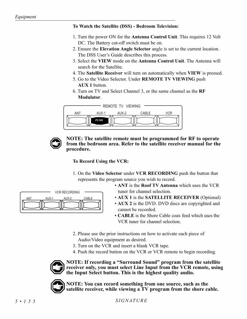
To Watch the Satellite (DSS) - Bedroom Television:
1. Turn the power ON for the Antenna Control Unit. This requires 12 Volt DC. The Battery cut-off switch must be on.
2. Ensure the Elevation Angle Selector angle is set to the current location. The DSS User’s Guide describes this process.
3. Select the VIEW mode on the Antenna Control Unit. The Antenna will search for the Satellite.
4. The Satellite Receiver will turn on automatically when VIEW is pressed.5. Go to the Video Selector. Under REMOTE TV VIEWING push
AUX 1 button.6. Turn on TV and Select Channel 3, or the same channel as the RF
Modulator.
NOTE: The satellite remote must be programmed for RF to operatefrom the bedroom area. Refer to the satellite receiver manual for theprocedure.
To Record Using the VCR:
1. On the Video Selector under VCR RECORDING push the button that represents the program source you wish to record.
• ANT is the Roof TV Antenna which uses the VCR tuner for channel selection.
• AUX 1 is the SATELLITE RECEIVER (Optional)• AUX 2 is the DVD. DVD discs are copyrighted and
cannot be recorded.• CABLE is the Shore Cable coax feed which uses the
VCR tuner for channel selection.
2. Please use the prior instructions on how to activate each piece of Audio/Video equipment as desired.
3. Turn on the VCR and insert a blank VCR tape.4. Push the record button on the VCR or VCR remote to begin recording.
NOTE: If recording a “Surround Sound” program from the satellite receiver only, you must select Line Input from the VCR remote, usingthe Input Select button. This is the highest quality audio.
NOTE: You can record something from one source, such as the satellite receiver, while viewing a TV program from the shore cable.
Equipment---------------------------------------------------------------------------------------------------------------------------------------------------------------------------------------------------------------------------------------------------------------------------------------------------------------------
S I G N AT U R E5 • 1 5 5
ANT AUX-1 AUX-2 CABLE
VCR RECORDING
REMOTE TV VIEWINGANT AUX-1 AUX-2 CABLE VCR
PUSH

S I G N A T U R ESECTION 6WATER SYSTEMS
6
WATER SYSTEM - General Information • 158MONITOR PANEL - Measurement & Calibration • 158
WATER TANK - FRESH FILL • 160WATER TANK - (FRESH) GRAVITY FILL • 160
PLUMBING MANIFOLD • 160WATER - CITY HOOK-UP • 161
WATER PUMP • 162Troubleshooting • 163
PRESSURE ACCUMULATOR TANK • 164WATER FILTERS • 164
WATER SYSTEM - Troubleshooting • 165WATER SYSTEM - Disinfecting Fresh Water • 166
Aqua-Hot Maintenance • 167TANK CAPACITIES • 167
WASTE WATER SYSTEMS - Waste Drain & Sewage Tanks • 168What Not to Put in Waste Holding Tanks • 168
Proper Waste Disposal • 168TOILET - Operating Instructions • 169
Cleaning • 169Maintenance • 169
Drain Traps & Auto Vents • 170Draining the Waste Holding Tanks • 170
What to Put into the Holding Tanks - Black Water Tank • 172What to Put into the Holding Tanks - Grey Water Tank • 172
COLD WEATHER USE • 173WINTERIZING - Fresh Water System Using Nontoxic Antifreeze • 174
WINTERIZING - Using Air Pressure • 175


This section contains information on the operation and care of the variouswater system equipment found in the motorhome. The motorhome is equippedwith two separate water systems. Optional water equipment will also be dis-cussed, so not all information may be applicable to your motorhome. Moredetailed information with CAUTION or WARNING instructions for the vari-ous equipment, other than what is found in this section, can be found in themanufacturer’s manual in the owner information box.
It is hard to imagine how much water is used everyday when you are athome. Newcomers to self-contained motorhomes soon discover that water doesnot last very long unless some basic water conservation techniques are applied.For instance, you can use less water while showering if you wet down, turn offthe water to soap up, then turn the water back on to rinse off. This way, a suffi-cient shower can be taken using five gallons or less of water.
Fresh Water System:The fresh water system consists of: fresh water tank, water pump, pressure
accumulator tank, Manabloc Plumbing Manifold, gravity fill connection, waterfilters and a city/fresh water connection.
Waste Water System:The waste water system consists of: a waste holding tank (grey water), a
sewage holding tank (black water), flush system, toilet and drains.
-
The motorhome is equipped with a monitor panel. Features include: a com-bination gauge that reads all water tanks (fresh, grey and black) and LP Gaslevels. separate AC and DC voltage indicators, water pump on/off switch, gen-erator start/stop switch and the RC7GS inverter remote panel.
Meters:The meters for voltage and amperage monitor the AC voltage values. Each
pair of volt and amp meters monitor one of the two “hot” supply lines of the240 Volt system. Voltage and amperage values are measured inside the ACbreaker panel. These meters are useful guides indicating correct, high or low
Water Systems------------------------------------------------------------------------------------------------------------------------------------------------------------------------------------------------------------------------------------------------------------------------------------------------------------------
S I G N AT U R E 6 • 1 5 8
WATER SYSTEMGeneral Information
MONITOR PANELMeasurement &
Calibration
030
60 90 120
150 010
20 3040
50
030
60 90 120
150 010
20 3040
50
Monitor Panel.

AC voltage conditions. The meters monitor AC power supplied from eithershore power or the generator.
Generator Switch:This switch starts and stops the generator.
NOTE: If the auto-gen start system is programmed, the system willoverride the generator start/stop switch. The RC7GS remote will thenhave to be used to manually start or stop the generator.
Tank Measurement:To measure the level of any holding tank, push the switch on the monitor
panel corresponding to the tank you wish to measure.
NOTE: If the domestic batteries are not at a full state of charge tankreadings will not be accurate.
Calibration:The monitor panel is calibrated at the factory for accuracy and
should not require adjustment. If the system is displaying incor-rectly calibration may be necessary.
• Completely fill the tank to be calibrated. • Locate the three adjustment screws (one for each tank)
behind the monitor panel. • Using the adjustment tool simultaneously push the button
for the tank and rotate the adjustment screw until a full tank reading is obtained.
• Repeat the procedure as necessary for the remaining tanks.•The water tank sensors are located on the curbside of the
motorhome, at the end of the holding tanks.
Water Systems---------------------------------------------------------------------------------------------------------------------------------------------------------------------------------------------------------------------------------------------------------------------------------------------------------------------
S I G N AT U R E6 • 1 5 9
Test Points on Monitor Panel
Monitor Adjustment Tool.
Tank Sensors
Grey WaterHolding Tank
Black WaterHolding Tank
Fresh Water Tank
Sensor Strips

• Connect the hose to city/fresh water hook-up located in the service center on the roadside of the motorhome.
• The city water valve must be in the OPEN position.• Turn on the water supply.• The water pump should be in the OFF position.• The fresh water tank has an overflow located on the curbside of the
motorhome. When the water starts to come out the overflow pipe shut the water supply off as soon as possible.
NOTE: When connecting the motorhome to fresh water be sure touse a hose manufactured and labeled for potable water to ensurethat the hose will not flavor the water.
The gravity fill inlet allows fluids to be introduced directlyinto the fresh water tank. When dry camping water can bepoured directly from a container into the fresh water tank. Thegravity fill inlet can be used to pour disinfecting solution intothe fresh water tank or when using potable RV antifreeze towinterize the fresh water system. Use only potable watersources, solutions and delivery systems when using the gravityfill inlet.
Filling the Tank:1. Unscrew fill cap taking care to keep cap and inlet clean.2. Insert potable water hose into inlet.3. Fill tank until water overflows from inlet.
NOTE: When filling tank do not leave hose unattended.
The Manibloc water manifold system separates the main hot andcold lines. The main hot and cold inputs are divided into the individualbranch lines. Water flows unrestricted with no hidden fittings locatedbehind walls.
Each faucet or appliance water line may be turned off individually.The hot water valves are located on the left and the cold water valvesare on the right. Use the key provided to turn on or off any water line.When key is horizontal the water line is open. Turning the key to thevertical position shuts that water line off. Each water line is labeled foreasy reference. Snap the Manibloc key into the storage position afteruse.
Water Systems------------------------------------------------------------------------------------------------------------------------------------------------------------------------------------------------------------------------------------------------------------------------------------------------------------------
S I G N AT U R E 6 • 1 6 0
WATER TANK - FRESH WATER
FILL
1. Gravity Fill Opening. 2. Vent Opening.
1
2
WATER TANK - (FRESH) GRAVITY FILL
1. Manabloc tee handle. Eachwater line can be turned off.
PLUMBING MANIFOLD

Water Systems---------------------------------------------------------------------------------------------------------------------------------------------------------------------------------------------------------------------------------------------------------------------------------------------------------------------
S I G N AT U R E6 • 1 6 1
• Connect the hose to city/fresh water hook-up located in servicecenter on the roadside of motorhome.
• The city water valve must remain in closed position.• Turn on the water supply.• The water pump can either be in OFF position or in ON position.
It will not affect the water pump to leave it on.• City/fresh water connection has a built in pressure regulator and
one way check valve that protects the motorhome to 45 lbs.
CAUTION: Some water sources develop high water pressure, particularly in mountainous regions. High water pressure is anything over 55 psi (pounds per square inch). Excessive water pres-sure may cause leaks in water lines and/or damage the water heater.The motorhome comes with a pressure regulator which should alwaysbe connected to the city water faucet to regulate hose and coach pres-sure.
WATER - CITY HOOK-UP

The water pump pressurizes the fresh water system when the motorhomeis not connected to city water. The water pump is totally automatic and self-priming, operating on demand as water is used. The pressure equalizer tankrelieves the water pump from cycling when a small amount of water is used.The water pump is located in a storage compartment of the motorhome.
WARNING: Before leaving your coach for extended periods oftime (i.e. overnight or longer) be sure that the city water and allwater pumps have been turned off. Damage from neglect will bethe responsibility of the owner, not Monaco Coach Corporation.
Latching ControllerThe latching controller circuitry allows multiple switch locations to
operate the water pump. Pressing one of the water pump switches pro-vides a momentary ground signal to the latching controller, turning thewater pump on or off from any location. An indicator lamp at eachswitch location illuminates when the water pump is on.
The water pump may be operated from the following locations:• The monitor panel• The bathroom• The service center
To turn the water pump on or off:• Momentarily press the water pump switch. The indicator lamp
will illuminate when the water pump is turned on.
CAUTION: Do not continue water pump operation when the fresh waterholding tank is empty. Damage to the water pump or electrical supplysystem may result.
To start pump after unhooking city water supply or first time use proceed as follows:
• Fill the fresh water tank.• Open all valves and faucets except the drain valves. This
includes hot and cold water valves, all faucets and shower. • Turn the water pump on and wait for the water lines and the
hot water tank to fill. • Close each faucet when it delivers a steady stream of water
(cold water faucets first).
Water Systems------------------------------------------------------------------------------------------------------------------------------------------------------------------------------------------------------------------------------------------------------------------------------------------------------------------
S I G N AT U R E 6 • 1 6 2
WATER PUMP
Water Pump.
Water Pump Switch.

Vibration induced by road conditions can cause the plumbing or pump hard-ware to loosen. Check for system components that are loose. Many symptomscan be resolved by tightening the hardware. Check the following items:
The water pump will not start/blows the fuse:• Check the electrical connections, fuse or breaker, main switch and
ground connection.• Check the electrical connections at the latching controller.• Is voltage present at the pressure switch? Bypass the pressure switch.• Is the latching controller grounding the water pump?• Check the charging system for correct voltage and good ground.• Check for an open or grounded circuit or motor. • Check for seized or locked diaphragm assembly (water frozen).
The water pump will not prime/sputters: (No discharge/motor runs):• Is the strainer clogged with debris?• Is there water in the tank, or has air collected in the hot water heater?• Is the inlet tubing/plumbing sucking in air at plumbing connections (vacu-
um leak)?• Check for proper voltage with the pump operating.• Look for debris in the pump inlet/outlet valves or dry/swollen valves. • Check the pump housing for cracks or loose drive assembly screws.
The water pump will not shut-off/runs when the faucet is closed:• Check to see if the fresh watertank fill valve is completely closed. • Check output side (pressure) plumbing for leaks and inspect for a leaky
toilet or valves. • Look for loose drive assembly or pump head screws. • Are the valves or the internal check valve held open by debris or is the
rubber swollen?
The water pump is noisy or rough in operation:• Check for plumbing which may have vibrated loose. • Does the mounting surface multiply noise (flexible)?• Check for mounting feet that are loose or compressed too tight.• Look for loose pump head to motor screws.
The water pump is rapid cycling:• Look for restrictive plumbing/flow restrictors in the faucets or shower
heads.
Water Systems---------------------------------------------------------------------------------------------------------------------------------------------------------------------------------------------------------------------------------------------------------------------------------------------------------------------
S I G N AT U R E6 • 1 6 3
Troubleshooting

The pressure accumulator tank is mounted in the water bay nearthe water pump. The accumulator tank will need to have mainte-nance checks completed bi-monthly. The accumulator features:
1. Smooth flow from the faucets. 2. Reduced water pump cycling. 3. A precharged air cushion. 4. Elimination of pulsations and water hammer.5. Pressure of water at faucets.
The accumulator tank has a tire valve for checking the air pres-sure in the tank. The precharged pressure must not exceed thewater pump cut-in pressure, the pressure at which the pumprestarts. The water pump has a cut-in pressure at 25 psi. Air pres-sure in the accumulator tank should be set at 18 to 22 psi andshould not exceed 25 psi. To check the air pressure in the accumu-lator tank the water pump and city water will need to be off so thatthe water pressure is relieved. Open a faucet to relieve the remain-ing water pressure. Using a tire air pressure gauge, one which reads low airpressure, check the accumulator tank pressure bi-monthly. In the event youneed to add air pressure to the accumulator tank, a manual pump is recom-mended. Airflow and pressure from a compressed air system can overchargethe tank too quickly causing the tank to rupture.
A 2-stage filtration system if used and consists of the following filters:
• First Stage 5 Micron Sediment Filter: For reduc-tion of suspended solids, dirt and rust down to 5microns in size. Life expectancy varies with incom-ing water condition. Recommended change of sixmonths to one year depending on incoming waterquality and use.
• Second Stage 56 Cubic Inch Granular ActivatedCarbon Filter: Improves water quality by reducingvolatile organic chemicals, chlorine, tastes andodors. Capacity of 1,500 gallons. Recommendedchange of six months to one year depending onincoming water quality and use.
Water Systems------------------------------------------------------------------------------------------------------------------------------------------------------------------------------------------------------------------------------------------------------------------------------------------------------------------
S I G N AT U R E 6 • 1 6 4
PRESSUREACCUMULATOR
TANK
WATER FILTERS
Remove tank valve cap to check air pressure.
Primary meshtype cartridge.
Inflow
Outflow
Secondaryplastic typecartridge.

The filter elements will need to be removed and the filter bowls reassem-bled, without the elements, before disinfecting the water system with a chlorinebleach solution. To change the filter elements use the following procedure.
To Remove:• Turn off the water supply and the water pump. Open the faucet to
bleed off pressure.• Unscrew the filter bowl from the filter head.• Remove the old element and empty any remaining water in the
bowl.
To Install:• Place the elements in the bowls, observing primary and secondary
filter locations.• Screw the bowls onto the filter heads, hand tight.• Turn on the water pump or city water. • Open the outside faucet and purge air from the filter assembly.• Check for leaks.
Water system problems and leaks usually fall into two categories: systemproblems and problems caused by improper use or lack of attention. Theseproblems usually stem from improper winterizing, poor maintenance, roadvibration and campsite water pressure variations. Check all plumbing connec-tions for leaks at least once a year. If the water pump runs when a faucet is notopen, check for a water leak. If a water line or fitting is leaking try to tightenthe fitting. If the leak has not stopped use the water manifold key to shut-off thewater supply valve. Have the leak repaired before returning the supply line toservice.
NOTE: A small water leak can cause severe water damage. Shut-offthe water supply and have the leak repaired.
Water Systems---------------------------------------------------------------------------------------------------------------------------------------------------------------------------------------------------------------------------------------------------------------------------------------------------------------------
S I G N AT U R E6 • 1 6 5
Water Filter Removal Wrench.
WATER SYSTEM - Troubleshooting

Water Systems------------------------------------------------------------------------------------------------------------------------------------------------------------------------------------------------------------------------------------------------------------------------------------------------------------------
S I G N AT U R E 6 • 1 6 6
Disinfecting water system with chlorine bleach (superchlorination) pro-tects you and your family from bacteriological or viral contamination fromany common water source.
You should disinfect the water system:• If your motorhome is new.• If your motorhome has not been used in a long time.• Every three months.
NOTE: An independently operated water pump with garden hose connections and a container to hold prepared solution may bedesired to perform this task. The gravity fill may also be used toperform the task. Remove cap off the gravity fill. Add the solutionto the fresh water tank. When finished, secure the gravity fill cap.
CAUTION: Do not use vinegar to disinfect water system on unitsusing Aqua-Hot Heating Systems. Vinegar will deteriorate coppertubing.
Use the following procedures to disinfect water system:• Remove the filter elements from the filters and reassemble the filters
without the elements (see "Filter").• Prepare a chlorine bleach solution using 1 gallon water and 1/4 cup of
chlorine bleach. Use 1 gallon of solution for every 15 gallons of tankcapacity. Example: Add 2-2/3 gallons solution to a 40 gallon tank.Add 4-2/3 gallons solution to a 70 gallon tank. Add 6-2/3 gallons to100 gallon tank. This mixture puts a 50 ppm (parts per million) disin-fecting solution in the water system. This concentration will act as aquick-kill dosage for harmful bacteria, viruses and slime-formingorganisms. Concentrations higher than 50 ppm may damage thewater lines and/or tanks.
• Drain the fresh water tank. Close the drain and pump the solution (ifdesired) into the fresh water tank using an independently operatedpump and a garden hose connected to City Water Hook-Up on thewater control panel. It can be poured into the fresh tank using thegravity fill and a funnel. Run the water until you smell a distinctchlorine bleach odor.
• Allow the system to stand for four hours.• Drain the system and flush with fresh water. The drain is located in
the outside water service compartment. Install new water filters.Thoroughly flush with fresh water until no chlorine bleach taste orsmell is detected in the water system.
WATER SYSTEM- Disinfecting
Fresh Water

If not properly and thoroughly rinsed chlorine bleach or other concentratedchlorine bearing chemicals can cause failure to the Aqua-Hot’s Domestic WaterLoop (copper tubing). The Aqua-Hot’s copper tubing is rated for use with freshwater and winterization solutions only. Periodic flushing with other commonhousehold chemicals, including bleach, will have little or no effect on the productif properly rinsed with the fresh water afterwards. Failure of copper tubing, espe-cially soft or flexible copper, can result if materials other than water or winteriza-tion solutions are allowed to reside inside the piping for extended periods as dur-ing storage or other periods of non-use. The most common cause for failure isdue to an extended exposure to chlorine, solutions containing chlorine (i.e.bleach) or hydrochloric acid.
Water Systems---------------------------------------------------------------------------------------------------------------------------------------------------------------------------------------------------------------------------------------------------------------------------------------------------------------------
S I G N AT U R E6 • 1 6 7
Aqua-HotMaintenance
TANK CAPACITIES
TANK CAPACITIES (Approximate Gallons)34’ Model 36’ Model 38’ Model 40’ Model 40’ Double Slide
Diesel Fuel 118 118 118 118 118Water Heater 10 10 10 10 10Grey Holding Tank 60 60 60 60 60Black Holding Tank 40 40 40 40 40Fresh Water Tank 100 100 100 100 100LP Gas Tank* 45 45 45 45 45
* Actual filled LP - Gas capacity is 80% of listing due to safety shut-off required at tank.

The waste drainage system was designed to provide adequate and safestorage and/or discharge of waste materials. All materials used in fabricationand installation of system is tested by a nationally recognized testing labora-tory. The entire fabricated waste system is factory tested in accordance withAmerican National Standards Code A119.2. The drainage system uses ABSplastic piping and fittings connected to sinks, shower, toilet and holdingtanks and provides for their drainage to an outside termination. Themotorhome should be reasonably level for optimum operation of the systems.There are two separate waste water systems: one for waste water (greywater) and one for sewage waste (black water). Each has its own storage tankcontrol valve and both empty through a sewer drain hose. When traveling, itis recommend both holding tanks be empty or less than half full.
• Do not use strong or full strength detergents to deodorize anddisinfect. Use odor control chemicals made especially forholding tanks.
• Do not put automotive antifreeze, ammonia, alcohol or acetonein holding tanks. Some chemicals will dissolve plastic.
• Do not put large table scraps in the tanks. They could get stuckin or damage the valve seals.
• Do not flush facial tissues. They are treated chemically tostrengthen them and will not dissolve like toilet paper. Specialholding tank tissues are available at most RV supply stores.White toilet paper dissolves faster than colored papers.
Most State Parks have strict regulations about discharging wastes exceptinto authorized disposal systems. Dumping raw sewage from toilet holdingtanks, except at authorized dumping stations, is universally prohibited.
Most National, State and private parks have either a central dump facilityor campsite hook-up for sewage. Many of the modern rest areas along theinterstate now have dump stations available. You will find a list of dumpingstations from coast to coast in Woodall’s Campground Directory, TrailerLife’s RV Campgrounds and Services Directory, Rand McNally’sCampground and Trailer Park Guide, Good Sam Park Director (Good SamClub) and other publications. Some major oil companies offer dump facilitiesat selected stations. Plan ahead in locating proper and legal disposal sites forholding tank waste.
Water Systems------------------------------------------------------------------------------------------------------------------------------------------------------------------------------------------------------------------------------------------------------------------------------------------------------------------
S I G N AT U R E 6 • 1 6 8
WASTE WATERSYSTEMS
Waste Drain &Sewage Tanks
Proper WasteDisposal
What Not to Put in WasteHolding Tanks

The toilet is an electrically operated drop-through type toilet using approxi-mately two quarts of water per flush. Wastewater is flushed from the bowlthrough a hopper and drops directly into a holding tank. A flapper valve at thebottom of the bowl holds fresh water in the bowl and seals out odors from theholding tank.
• When the flush lever is operated, a motor driven cam begins toturn which opens the flapper valve at the bottom of the bowl,allowing the waste water to flow down into a holding tank.Simultaneously the water solenoid valve opens, allowing freshwater to flow from the rim and rinse the bowl. The cam contin-ues to turn and the flapper will close after approximately 4-5 sec-onds.
• After the flapper has closed, fresh water continues to enter thebowl to a predetermined level until the timer allows adjustmentsof the water level in the bowl to compensate for the water pres-sure fluctuations. A vacuum breaker is provided as an anti-siphon device.
Maintenance- If the toilet is to be out of service for a period of time, spray100% silicone on the flapper seal when the flapper is open to prevent it frombecoming dry.
NOTE: Holding flush lever down longer than necessary results inexcessive water usage.
The toilet should be cleaned regularly for maximum sanitation and opera-tional efficiency. Clean the toilet bowl with a mild bathroom cleaner. Do not usechlorine or caustic chemicals, such as drain opening types, as they will damagethe seals.
Clean out the system by flushing several gallons of fresh water through withone cup of dry laundry detergent. Add odor control deodorant, in the amountspecified for your holding tank capacity, after cleaning and every few days dur-ing use.
To find leaks, check behind or under toilet. Take four or five sheets of toilettissue and wipe all the seams and waterline connections. Start at the top of theunit and work downward. When the tissue comes in contact with leaking waterit will immediately change texture.
NOTE: If the motorhome is in storage for six months it is a good ideato spray sicicone on the toilet valve and work it back and forth, atleast once a month, silicone will evaporate in about 30 days.
Water Systems---------------------------------------------------------------------------------------------------------------------------------------------------------------------------------------------------------------------------------------------------------------------------------------------------------------------
S I G N AT U R E6 • 1 6 9
Maintenance
TOILETOperatingInstructions
Cleaning

Sinks, shower and clothes washer drains incorporate awater trap or “P-trap” and auto vents to prevent waste waterholding tank odor from entering the motorhome. These P-traps are usually within 54” of a vent tee. These traps musthave water in them to block odors. During storage water canevaporate and allow odor into motorhome. If odor is detect-ed run water into sinks, shower and clothes washer to filldrain traps. The auto vent by design is to assist in the flowof water in the drain lines. They enable a smooth flow ofwater in the drain without creating a vacuum.
The auto vent, if stuck in the open position, can allowgrey odors to enter the motorhome. These auto vents alsodouble as “clean outs” in the event you have to snake out aline.
NOTE: Most chemical mixtures for holding tankodor control are poisonous. Follow the product man-ufacturer's directions and warnings when using anyholding tank additive.
NOTE: During cold weather antifreeze must be added to the draintraps.
When parked in an area with a sewer hook up, “exercise” the drain pipebefore hooking up the sewer hose. Swivel the pipe up and down by firmlygrasping both sides of the sewer drain pipe hose connection. This will exer-cise the O-rings. Leave the drain pipe pointing up to prevent any residualmaterial from running out.
Attaching the Sewer Hose:• Turn the drain end cap counterclockwise and remove it from the
drain pipe. • Unscrew the hose access deck plate from the bottom of the water
service compartment. Feed the adapter end of the drain hose upthrough the hole and install the hose adapter onto the drain pipe.
• Rotate the drain pipe downward for maximum flow.• Straighten and secure hose to avoid recoil. Attach the end of the
hose to the sewer connection at the dump station.
NOTE: Ensure sewer hose connections and hose clamps are secure before use.
The grey water holding tank valve (small valve) remains open when con-nected to the sewer hook-up. The black water holding tank valve (large valve)remains closed at all times except when dumping the sewage tank. Whenpreparing to dump the black water holding tank, first close the grey water tank
Water Systems------------------------------------------------------------------------------------------------------------------------------------------------------------------------------------------------------------------------------------------------------------------------------------------------------------------
S I G N AT U R E 6 • 1 7 0
Drain Traps & Auto Vents
Vent Tee
Draining the Waste Holding
Tanks

valve. Allow the grey water tank fluid to accumulate until the tank is at leasthalf full or fill by running cold water through the sink and shower drains. Donot overfill the grey water holding tank.
To aid in the removal of solids, dump the black tank when the tank is at least50% full. If it is necessary to dump the black tank when the level is below 50%add water by using the sewage tank flush system.
• With black valve closed use the sewage tank flush system toincrease the holding tank level.
• When adding water to the tank using the sewage tank flush sys-tem, closely observe the tank level by using the monitor paneltank gauge indicator to prevent the tank from being overfilled.
• The sewage tank flush system should never be operated unattend-ed.
Dumping the Waste Holding Tanks:• With the grey water valve closed, open the black water valve to
drain the tank.• Flush the sewage tank. Connect a separate non-potable water sup-
ply hose with pressure regulator to the sewage tank flush connec-tion on the water service panel. For sanitary reasons, be sure notuse the potable city water hose for this procedure. The large gatevalve remains open throughout the flushing cycle. Turn the wateron and flush the black water system for approximately two min-utes. Ensure water is flowing freely through the sewer hose.
• When finished flushing the system, turn the water off and closethe black water valve.
• Open the grey water valve.• The waste water tank is flushed by running two gallons of water
down a sink drain.• If applicable, close the grey water valve for transit.• Disconnect and flush the drain hose with either the non-potable
water supply hose or the exterior faucet. Secure the sewer hose inthe travel location. Disconnect and stow the non-potable hose.
• Install the end cap (required by law in some states) and deck platewhen in transit to prevent leakage. Swivel sewer drain pipe up.
NOTE: Periodically lubricate the O-ring on the sewer hose adapter with sili-cone spray. Use care when connecting the hose adapter to the drain pipe in coldweather.
WARNING: When using the black tank flush do not leave the motorhomeunattended or flooding may occur. The sewage tank flush system should beused each time the black water holding tank is dumped. Failure to routine-ly use the sewage flush system will result in a clogged spray nozzle. Turnoff the water supply to the black tank flush when finished.
Water Systems---------------------------------------------------------------------------------------------------------------------------------------------------------------------------------------------------------------------------------------------------------------------------------------------------------------------
S I G N AT U R E6 • 1 7 1

The black water sewage tank stores toilet drain waste only. Before usingthe toilet, treat the sewage holding tank with water that is mixed with an odorcontrolling chemical. These chemicals are readily available at any RV supplystore. The chemicals are poured into the holding tank through the toilet. Addthree gallons of water to the holding tank first then mix the chemicals withapproximately one gallon of water and add to the hlding tank. Be careful notto spill the chemical on your hands, clothing or carpet as it can cause perma-nent stain. Extremely hot weather areas may require adjusted amounts ofchemical to help with odor control. Repeat the chemical pre-change to theholding tank each time the tank is dumped.
CAUTION: Do not use any products that contain petroleum distillatesor ammonia in place of an RV odor controlling chemical. Petroleum dis-tillates or ammonia will damage the ABS plastic holding tanks and seals.
The grey water waste tank stores the sink, shower and clothes washerdrain water. No chemical is required in this holding tank however, a wasteholding tank can produce odors. A reduced mixture of chemicals may beused for odor control.
Prior to dumping the the waste holding tanks, be sure there is enough liq-uid in the holding tanks to provide a smooth flow through the valve drainpipe and drain hose. When sufficient liquid is in the tank a swirling actionwill result that should take accumulated solid wastes along with the wasteliquid when the tank is dumped. The tanks should be emptied when theyreach ½ full, or weekly, to prevent stagnation and overfilling.
Water Systems------------------------------------------------------------------------------------------------------------------------------------------------------------------------------------------------------------------------------------------------------------------------------------------------------------------
S I G N AT U R E 6 • 1 7 2
What to Put into the Holding Tanks
- Black Water Tank
What to Put into theHolding Tanks
- Grey Water Tank

Cold Weather Use:A motorhome is not designed for extended use in below freezing
(32° F/0° C) weather; however, you may not experience any problems as longas the temperature does not drop too low. Interior water lines, fixtures, waterstorage tanks and pumps are normally protected from moderate freezing temper-atures, as long as the furnace is operating. Exposed drains may freeze quickly. Ifin doubt about what temperature the motorhome will tolerate, winterize with apotable antifreeze.
Storage:If storing the motorhome where freezing temperatures may occur, the
domestic fresh water loop will need to be completely drained of water. Whendraining the domestic fresh water system start off by draining the fresh watertank. Open the drain lever for the fresh tank and allow the water to drain.
NOTE: Ice makers, water filters, water purifiers, water heaters,washers and the Aqua Hot all use domestic water and should bedrained and stored in accordance with the manufacturer’s recom-mendation for winterization.
How you decide to store your motorhome and protect the water lines is up toyou. You may elect to have the water lines blown out with air to remove stand-ing water or fill the lines using an approved FDA RV antifreeze. When usingeither method, all the interior and exterior faucets will need to be opened andclosed, one at a time, to verify that all water has been purged. All low pointdrains should be opened, and holding tanks emptied.
Water Systems---------------------------------------------------------------------------------------------------------------------------------------------------------------------------------------------------------------------------------------------------------------------------------------------------------------------
S I G N AT U R E6 • 1 7 3
COLD WEATHERUSE

To use air pressure to winterize your motorhome you will need access toan air compressor and adapter to connect the air line to your water system.Adapters can be found at any RV supply store. System pressure should notexceed 50 psi. when hooked to the water lines. Higher pressure will damagethe lines.
1. Remove the water filter elements from the filters and reassemble the fil-ters without the elements (see “Water Filter”).
2. Drain the fresh water tank by opening the valve located in the outsidewater control service compartment of the motorhome.
3. Open the water heater and the low-point drains. Turn knobs to open thedrains. Opening the low point drains clears the water out of the hot andcold water lines. Leave the low-point valves open until you are ready touse the motorhome again.
4. Let all the water drain. Turn the pump on and allow it to run so that allthe water is cleared out of the pump and lines. Turn the pump off.
5. After the water lines are drained, hook an air hose to the city water con-nection located on the water control panel in the outside service com-partment. Blow out the water lines until no further water can be seencoming out of the drain lines. Do not exceed 50 psi in the water linesand faucets.
6. Open all faucets (including the outside spigot), one at a time while theair is on, to clear water from the faucet supply lines. Do not forget todrain your shower.
7. While the air is on, hold the spray nozzle (located right next to the toi-let) open until the water has quit running. Hold the toilet flushpedal/handle down until the water has stopped running.
8. Unhook the air hose and close the city water connection.9. You will need 1 gallon of RV antifreeze to protect various water drain
lines in your motorhome. Pour 1 pint into both the kitchen and bathshower drains. Pour 2 pints into the bath sink drain, with some of theantifreeze going into grey tank to protect the drain valve. While holdingdown the flush pedal, pour another 3-1/2 pints into the toilet, letting theantifreeze run into the black tank to protect the valve. Pour the last pintof antifreeze into the toilet after you have released the flush pedal.Micropher toilets may be stopped in the middle of the flush cycle.Locate the on/off switch below the tank lid. Initiate the flush cycle thenturn the switch off in the middle of the flush cycle. Use a soft cloth towipe out the sinks and shower after you pour in the antifreeze to pro-tect the surfaces from stains.
10. Leave the low-point drains open until you are ready to use yourmotorhome again.
WARNING: When draining the low point hot water drain lines and the waterheater, be sure the water is cool. Hot water from the lines can burn you.
Water Systems------------------------------------------------------------------------------------------------------------------------------------------------------------------------------------------------------------------------------------------------------------------------------------------------------------------
S I G N AT U R E 6 • 1 7 4
WINTERIZING- Fresh Water System
Using NontoxicAntifreeze

Ten gallons of FDA approved approved RV antifreeze will be required towinterize the motorhome.
1. Remove the water filter elements from the filters and reassem-ble the filters without the elements (see “Water Filter”).
2. Open all of the low point drains (next to the aqua-hot) and thedrain valves to drain: the fresh water tank, water heater tank,holding tanks and fresh water lines.
3. Close all faucets, drain valves and low point drains.4. Pour the antifreeze into the fresh water tank using the fresh
water gravity fill.5. Turn ON the system water pump and operate each faucet indi-
vidually until a small amount of antifreeze is present.6. Close off the faucets. 7. Open the shower faucets and toilet valves to allow a small
amount of antifreeze to run into the holding tanks.8. Use a soft cloth to wipe out the sinks and shower to protect sur-
faces from antifreeze stains. 9. Exterior faucet should be opened and closed using the same
procedures as the interior faucets.10. If the motorhome is equipped with an ice maker, remove the
3/4 inch fitting and flush antifreeze through the water line. 11. Disconnect the power supply line affecting water pump opera-
tion.
For de-winterization, drain off the fresh tank and fill the fresh tank withwater. Reconnect the power supply line for the water pump. Operate all faucets,one at a time, until clear water is present.
WARNING: You should use only non-toxic RV antifreeze that is specifically made for potable water systems. Automotive antifreeze, ifingested, can cause blindness, deafness or death.
WARNING: It is recommended that this procedure be done by a qualified RV service technician familiar with motorhomes, such as your authorized selling dealer.
Water Systems---------------------------------------------------------------------------------------------------------------------------------------------------------------------------------------------------------------------------------------------------------------------------------------------------------------------
S I G N AT U R E6 • 1 7 5
WINTERIZING -Using Air Pressure

S I G N A T U R ESECTION 7 LP-GAS SYSTEMS
LP-GAS SYSTEM • 178 LP-GAS DETECTOR • 179
Operation • 179Testing • 179
Care of the Detector • 180MONITOR PANEL MEASUREMENT • 181
CHECKLIST - LP-Gas Emergency Procedures • 181LP-GAS TANK • 182
LP-GAS REGULATOR • 183LP-GAS CONSUMPTION • 184
LP-GAS DISTRIBUTION LINES • 184LP-GAS TANK - OPERATION • 184
LP-GAS FUNDAMENTALS • 185
7


This section contains information and knowledge for the operation andcare of the various Liquefied Petroleum (LP-Gas) system equipment found inthe motorhome. The motorhome is equipped with several appliances and vari-ous equipment which are capable to operate on LP-Gas. Some items discussedmay not be applicable to your motorhome. More detailed information withCAUTION or WARNING instructions for the various equipment, other thanwhat is found in this section, can be found in the manufacturer’s manual inthe owner information box.
All components for your motorhome LP-Gas systems are approved for usein camping vehicles by a nationally recognized testing laboratory. When prop-erly handled, LP-Gas is a clean-burning dependable fuel for heat producingcomponents. The LP-Gas tank mounted in your motorhome contains liquidpetroleum gas under high pressure. As fuel is used, liquid gas vaporizes andpasses through the tank valve to a regulator that automatically reduces pres-sure. Low-pressure gas is then distributed to components through a pipe mani-fold system.
Component lighting problems are commonly caused by an improperlyadjusted gas regulator. Never attempt to reset regulator yourself. Have yourdealer or an authorized service person make adjustments.
In higher elevations or extreme cold weather (10° F/-21° C or lower) youmay experience a shortage of LP-Gas. You can adjust to this by not runningmore than one component at a time, such as turning off furnace while usingthe range. If you are going to be in higher elevations or cold climates for along period of time an authorized service person can adjust your LP-Gas regu-lator for these conditions.
We recommend that you have the LP-Gas system checked by an authorizeddealer at least once a year, and thereafter every extended trip. Although manu-facturer and dealer both test carefully for leakage, travel vibrations couldloosen fittings.
Leaks can be easily found by applying leak detector solution at connec-tions. If leak detector solution is not available a soapy water solution madewith dish soap can be used. Tightening fittings usually stops any leaks. If not,shut off main gas valve at tank and see your authorized dealer for repairsimmediately. Hand tighten tank valves only, do not use a wrench or pliers asover tightening may damage valve seats and cause them to leak. If you suspecta leak, which is an easily identified odor (smells like rotten eggs/sulfur) neverlight a match or have an open flame.
LP-Gas System------------------------------------------------------------------------------------------------------------------------------------------------------------------------------------------------------------------------------------------------------------------------------------------------------------------
S I G N AT U R E 7 • 1 7 8
LP-GAS SYSTEM

Provided for safety is a gas detector. This gas detector will detect both LP-Gas and Methane Gas. Liquefied Petroleum (LP) Gas is heavier than air,Methane Gas is lighter than air. LP-Gas will settle to the lowest point, generallythe floor of the motorhome. Methane Gas will rise. The gas detector is also sen-sitive to other fumes such as hair spray, of which most contain butane as thepropellant. Butane, like propane, is heavier than air and will settle to the floorlevel where it will be detected. When this occurs, press reset button to stop alertsound for 60 seconds.
The other combustibles which will be detected include alcohol, liquor,deodorants, colognes, perfumes, wine, adhesives, lacquer, kerosene, gasoline,glues, most of all cleaning agents and propellant of aerosol cans. Most arelighter than air in their vapor state and will only be detected when themotorhome is closed up.
Upon first application of power the LED will flash yellow for 3 minuteswhile the detector is stabilizing. At the end of the start cycle the LED will turnGreen indicating full operation. If detector senses unsafe levels of gas it willimmediately sound an alarm.
The gas detector operates on 12 volts, with a current draw less than 1/10thof one amp.
CAUTION: This detector will not alarm during the 3 minute warm upcycle.
Depress the TEST switch any time during the warm up cycle or while innormal operation. The LED should flash RED and the alarm should sound.Release the switch. This is the only way you should test your detector. The testfeature checks full operation of the detector.
WARNING: Test the operation of this detector after the motorhome hasbeen in storage, before each trip and at least once per week during use.
LP-Gas System---------------------------------------------------------------------------------------------------------------------------------------------------------------------------------------------------------------------------------------------------------------------------------------------------------------------
S I G N AT U R E7 • 1 7 9
LP Detector
Operation
Testing
LP-GAS DETECTOR

The Red LED will flash and the alarm will sound whenever a dangerouslevel of propane or methane gas is detected. The detector will continue toalarm until the gas clears or the Mute switch is pressed.
Procedures To Take During An Alarm:1. Turn off all gas appliances (stove, heaters, furnace),
extinguish all flames and smoking material.Evacuate, leave doors and windows open.
2. Turn off the propane tank valve. 3. Determine and repair the source of the leak. Seek
professional help if necessary.
CAUTION: Do Not re-enter until the problem is corrected.
Alarm MutePress the Test-Mute button when the detector is in alarm.
1. The Red LED will continue flash and the alarm willbeep every 30 seconds until the gas level hasdropped to a safe level.
2. The LED will flash Green until the end of the Mutecycle.
3. If dangerous gas levels return before the end of themute cycle the alarm will beep 4 times and return tophase 1.
4. After 2 minutes the detector will return to normaloperation (solid Green) or resound the alarm if dan-gerous levels of gas remain in the area.
Fault AlarmShould the microprocessor sense a fault in the gas detector, a fault alarm
will sound twice every 15 seconds. The LED will alternately flash Red toGreen and the MUTE switch will not respond to any command. The gasdetector must be repaired or replaced.
1. Vacuum the dust off the detector cover weekly (morefrequently in dusty locations) using the soft brushattachment of your vacuum.
2. Do not spray cleaning agents or waxes directly ontothe front panel. This action may damage the sensor,cause an alarm or cause a detector malfunction.
LP-Gas System------------------------------------------------------------------------------------------------------------------------------------------------------------------------------------------------------------------------------------------------------------------------------------------------------------------
S I G N AT U R E 7 • 1 8 0
Care of the Detector

LP-Gas System---------------------------------------------------------------------------------------------------------------------------------------------------------------------------------------------------------------------------------------------------------------------------------------------------------------------
S I G N AT U R E7 • 1 8 1
Tank Measurement - To measure level of a tank simply push button on dis-play panel corresponding to tank you wish to measure. Lights on panel will turnon in sequence indicating level of tank.
Calibration - The monitoring panel comes factory calibrated for accuracyand should not need to be adjusted.
If you smell gas (a rotten egg or sulfur smell) at any time, perform the fol-lowing steps immediately:
• Shut off gas appliances.• Manually turn off the main gas supply at the tank.• Do not attempt to operate any electric switch.• Open windows and doors.• Evacuate the motorhome.• Keep open flames, spark producing devices and smoking material out
of the area.• Contact a qualified service technician to find the source and repair
the gas leak.
WARNING: A fire or explosion from ignited gas or gas fumes canseriously injure you or cause death.
MONITOR PANEL MEASUREMENT
LP Tank Gauge
CHECKLIST-LP-GASEMERGENCYPROCEDURES

Woodall’s Campground and Trailer Guideand other publications list refueling stations.Many travel parks sell LP-Gas. Shut off the pilotlights, appliances and igniters before filling theLP-Gas tank to prevent a fire or explosion. Havea trained service person fill the LP-Gas tank.
The LP-Gas tank fill and bleed valves are located in the LP-Gas tank access outside com-partment. Caution the service technician, if yourtank is new and being filled for the first time, topurge any air from the tank before filling. Whenthe tank is filled to the proper level there isspace available for the conversion of liquid intogas. If a tank is over- filled it may vent pressure.When this happens you may detect a strong rot-ten egg odor near the tank and/or hear a hissingnoise.
WARNING: Turn off all pilot lights and appliances during therefueling of the motorhome and filling the LP-Gas tank to preventa fire or explosion.
LP-Gas exists in both the liquid and vapor state with the LP-Gas tank. A“Full” tank is approximately 80% liquid. The pressure inside the tank varieswith the temperature of the liquid. All tanks are required to be equippedwith a pressure relief device. The purpose of the relief valve is to release gasor liquid caused by overpressurization. You will notice the gauge at the tank,when full, will only read 3/4. Your monitor panel is adjusted to indicateFULL at this point.
If you are storing portable LP-Gas tanks (do not transport or store LP-Gas tanks, gasoline or other flammable liquids inside the motorhome) thatare not connected to an LP-Gas system, install an approved plug in the tankoutlet holes to prevent leaks. Do not store empty LP-Gas tanks. Keep openflame and spark producing materials away from the LP-Gas area. If thiswarning is ignored a fire or explosion could result. Shut off all appliancesand LP-Gas tank valves (located on side of LP-Gas tank underneath themotorhome) when the motorhome is in storage.
CAUTION: Pressure inside LP-Gas tanks can reach over 300 psi whenexposed to direct sunlight. A high pressure safety relief valve will purgeexcess high pressure if necessary. LP-Gas will stop vaporizing as theLP-Gas tank temperature approaches -40º F. Appliances which con-sume large amounts of LP-Gas, such as the water heater or furnace,will need to be operated in sequence in extremely cold environments.
LP-Gas System------------------------------------------------------------------------------------------------------------------------------------------------------------------------------------------------------------------------------------------------------------------------------------------------------------------
S I G N AT U R E 7 • 1 8 2
LP-GAS TANK
LP-Gas Tank

The regulator is the heart of an LP-Gas system.The LP-Gas in the tank is under high pressure. Theregulator reduces the pressure of gas so that it issafe to use with various appliances. The regulatoron the motorhome is a two-stage regulator. Simplyput, the first stage regulator reduces the full tankpressure down to a range of 10-13 psig. The secondstage further reduces the pressure down to an outletpressure of 0.4 psig (11 inches of column water). The regulator is equipped with avent so that it can breathe. This means that if pres-sure in the LP tank is too high the regulator willallow gas to escape through the vent until pressurereturns to a normal range. It is important to keep thevent clean and clear of obstructions or corrosion. Ifthe vent becomes clogged, pressure from LP tankcould cause a failure of the components. If younotice any corrosion contact a qualified LP-Gasservice technician. The regulator is mounted so thatthe vent faces downward. If the vent becomesclogged you can clean it with a toothbrush.
Under normal atmospheric conditions a LP regu-lator will not freeze, nor will the LP-Gas. The gaspassing through the regulator will expand and coolcreating moisture in the gas. This moisture will turnto ice which can build up and partially or totallyblock the orifice. The possibilities of freeze up isgreatly reduced with the two stage regulator.
Things you can do to prevent this freeze up are:
1. Ensure the LP tank is totally free of moisture prior to filling.2. Ensure the tank is not overfilled.3. Keep the valve closed when the tank is empty.4. A LP-Gas dealer will need to purge the tank if freeze up occurs.5. Have the LP-Gas dealer inject methyl alcohol in the tank.
WARNING: Do not attempt to adjust the regulator, it is preset at thefactory. If adjustments need to be made it requires special equipment.Failure to follow these instructions may result in a fire or explosionand cause severe personal injury or death. DO NOT ATTEMPT TOREENTER THE MOTORHOME UNTIL THE PROBLEM HASBEEN CORRECTED!
LP-Gas System---------------------------------------------------------------------------------------------------------------------------------------------------------------------------------------------------------------------------------------------------------------------------------------------------------------------
S I G N AT U R E7 • 1 8 3
LP-GAS REGULATOR
LP-Gas Regulator

Each gallon of LP-Gas produces approximately 92,000 BTU’s of heat. One27 gallon tank produces two million BTU’s. Total consumption depends on therate of usage by each appliance and the operating time. The stove and heatingsystems typically use the most gas. With sub-freezing temperatures and highwinds, consumption by the furnace can be very high. Check the tank level oftenin cold weather.
WARNING: LP-Gas is highly volatile and extremely explosive. Never usematches or open flame to test for leaks. Use only approved LP-Gas leak test-ing solution to test for leaks. Unapproved solutions can damage copper tub-ing and brass fittings. Never attempt to adjust LP-Gas regulators without theuse of proper equipment. Improper LP-Gas regulator adjustment will affectthe performance of LP-Gas operated appliances. Incorrect flame or explo-sion can occur. Only qualified personnel should preform any maintenance orrepair to the LP-Gas system.
A primary manifold black steel pipe running throughout the motorhome dis-tributes LP-Gas to secondary lines. All secondary lines leading to gas appliancesare made of copper tubing with flared fittings. If any lines rupture do not attemptto splice them. Always run a new line. We recommend gas distribution work beperformed by an authorized dealer or an authorized service technician. Whenremoving or servicing any gas appliance, manually close the main valve locatedon the side of the LP-Gas tank. This will prevent dangerous gas leakage thatcould result in an explosion and possible serious injury. If you suspect a gas leakget the system inspected and repaired by a qualified service technician as soon aspossible.
• Manually open the main shut-off valve located on theroadside of the LP-Gas tank.
• Turn off the manual valve on the LP-Gas tank when themotorhome is in between trips.
• Hand tighten the manual valve. Do not use a wrench orpliers to close the valve.
• The manual valve is designed to be closed by hand, overtightening may permanently damage the valve seat.
LP-Gas System------------------------------------------------------------------------------------------------------------------------------------------------------------------------------------------------------------------------------------------------------------------------------------------------------------------
S I G N AT U R E 7 • 1 8 4
LP-GAS CONSUMPTION
LP-GAS DISTRIBUTION
LINES
LP-GAS TANK -Operation
Torpedo Tank.Usable LP-Gas capacity is 44gallons.
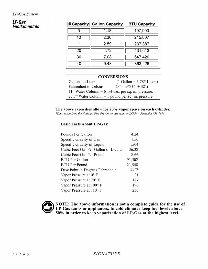
Basic Facts About LP-Gas:
Pounds Per Gallon 4.24Specific Gravity of Gas 1.50Specific Gravity of Liquid .504Cubic Feet Gas Per Gallon of Liquid 36.38Cubic Feet Gas Per Pound 8.66BTU Per Gallon 91,502BTU Per Pound 21,548Dew Point in Degrees Fahrenheit -44F°Vapor Pressure at 0° F 31Vapor Pressure at 70° F 127Vapor Pressure at 100° F 196Vapor Pressure at 110° F 230
NOTE: The above information is not a complete guide for the use ofLP-Gas tanks or appliances. In cold climates keep fuel levels above50% in order to keep vaporization of LP-Gas at the highest level.
LP-Gas System---------------------------------------------------------------------------------------------------------------------------------------------------------------------------------------------------------------------------------------------------------------------------------------------------------------------
S I G N AT U R E7 • 1 8 5
# Capacity Gallon Capacity BTU Capacity5 1.18 107,90310 2.36 215,80711 2.59 237,38720 4.72 431,61330 7.08 647,42040 9.43 863,226
The above capacities allow for 20% vapor space on each cylinder.*Data taken from the National Fire Prevention Association (NFPA). Pamphlet #58-1998.
CONVERSIONSGallons to Liters (1 Gallon = 3.785 Liters)Fahrenheit to Celsius (F° = 9/5 C° + 32°)11” Water Column = 6 1/4 ozs. per sq. in. pressure.27.7” Water Column = 1 pound per sq. in. pressure.
LP-Gas Fundamentals

S I G N A T U R ESECTION 8ELECTRICAL SYSTEM - HOUSE
8
DISTRIBUTION PANEL - HOUSE 110 • 205AC Panel • 205
Circuit Breaker • 207GFCI BREAKERS & OUTLETS • 207
DISTRIBUTION PANEL - HOUSE 12 VOLT • 208Fuses •209
Tools of the Trade • 210Know When to Say When • 210
BATTERY - HOW IT WORKS • 211Starting Battery • 211
Deep Cycle Battery • 212Battery Maintenance • 212
Battery Trays • 213Testing the Battery • 213
Reasons Why Batteries Fail • 215Battery Voltage & Current • 216
Battery Charge Time & Consumption Rate • 217Battery Specifications • 218
SOLAR PANEL (Optional) • 219Charge Controller Features • 220
Solar Panel Care • 220BULB USAGE - INTERIOR • 221
INTRODUCTION • 188Shore Power • 188
Generator • 188Inverter/Converter • 189
BATTERY DISCONNECT - HOUSE • 189BATTERY CUT-OFF SWITCH • 190
SHORE POWER HOOK-UP • 190Power Cord Reel • 191Transfer Switch • 192
GENERATOR - 120 AC • 192Starting the Generator • 192Stopping the Generator • 193
Powering the Equipment • 193Resetting the Circuit Breaker • 194
Generator Exercise • 194INVERTER/CONVERTER • 195
RC7 GS Remote • 195Stand-by Operation • 195
Battery Charging with the Inverter • 196Battery Temperature Sensor (BTS) • 196
Pass-through AC Power • 196Operating Display • 197
Meter Menu • 197Programming the RC 7 GS • 198
Adjusting Field Settings • 199Automatic Generator Start • 201
Equalize Charging • 203Re-booting the Inverter • 205


Electrical Systems - House------------------------------------------------------------------------------------------------------------------------------------------------------------------------------------------------------------------------------------------------------------------------------------------------------------------
S I G N AT U R E 8 • 1 8 8
INTRODUCTION
Generator
The motorhome 120/240 Volt AC system can be operated from three different power sources. Shore power is the most efficient and should beused whenever possible. The on board generator has a limited amount of 120Volts AC output power. This can be used when shore power is unavailable.The inverter/converter supplies silent AC power by using the motorhome’shouse batteries. This source has limited AC power output and should be usedsparingly.
The motorhome’s main 120 Volt AC circuit breaker panel is supplied withpower from two different sources:The 50 amp shore power cord or the onboard generator. The selection of the power source being used is done auto-matically by using an automatic electrical switching device known as thetransfer switch.
The power requirement for the motorhome is 50 amp 120/240 Volt ACsingle phase. If a 50 amp shore power service is available, the motorhome canbe directly plugged into the 50 amp shore power source with the suppliedshore power cord. If a 50 amp service is not available, proper electricaladapters will be required to convert the end of the 50 amp shore cord into acompatible type of connection for the available recepatacle. When plugged toanything other than a 50 amp service, appliances and other AC loads will haveto be operated in sequence.
NOTE: In many instances 50 amp shore service may not be available.Therefore, care will have to be taken when drawing power from multipleappliances and outlets so that the shore power service will not becomeoverloaded. Use only power cords which are rated at 50 amps. Avoidusing extension cords when connecting the motorhome to shore power.In most cases, extension cords are unsafe and inadequate for carryingthe level of current required by the motorhome.
The generator can be selected for use when AC shore power is not available. The motorhome’s on board generator has limited 120 Volt ACpower output capabilities. The generator’s maximum amount of output poweris specified in watts, calculated at an elevation of 500 feet above sea level.The maximum power available will decrease when there is an increase inaltitude. Ambient temperature also affects total maximum output. Fuel con-sumption is based upon a percentage of AC electrical load applied to the gen-erator. While using the generator, care will have to be taken when operatingappliances and outlets so that the generator will not be overloaded. The gen-erator is fueled from the main fuel tank.
Shore Power

The inverter/converter can be used for silent AC power if shore power is notavailable and using the generator is not going to be selected as a secondarypower source option. This device has limited AC power output measured inwatts. It operates only selected appliances and outlets. The inverter/converter istwo components in one: 1. Functioning as an auxiliary 120 Volt AC powersource that uses 12 Volt DC house battery power to invert to 120 Volts ACpower. 2. Using 120 Volts AC, supplied from either shore power or the genera-tor, and converting it to 12 Volts DC power to recharge the batteries.
The main house battery disconnect switch turns the battery power supply on or off. The domestic battery disconnect switch shuts off the 12 Volt DCpower to the following items: the inverter, the domestic fuse panel in the bedroom, the domestic fuse panel in the front run box and the domestic powersupply in the rear run box(s). Turn the main battery disconnect switch off when the motorhome is going to be stored or before performing electrical main-tenance on the motorhome. If possible, leave the motorhome plugged into anAC source with the battery disconnect switch on. This will help prevent thepossibility of dead batteries. Use of the battery cut-off switch at the entry doorwill not turn off all DC electrical items or other parasitic loads. There are smallparasitic loads that are present on the house battery. Some are federal mandateitems such as the LP-Gas detector. If an AC power source is not available andthe motorhome is not going to be used or is stored more than 48 hours, it is recommended to turn the battery disconnect switch off.
NOTE: The solar panels will charge the batteries with the disconnectswitch off.
WARNING: When the frame or other welding is involved for motorhomerepair or modification, the following precautions are required to protectelectronic components in the motorhome chassis:1. Disconnect the (+) positive and (-) negative battery connection, and any
electronic control ground wires connected to the frame or chassis.2. Cover electronic control components and wiring to protect from hot
sparks.3. Disconnect the wiring harness connectors at the transmission electronic
control unit. Open bed storage compartment, open engine access door. The transmission ECU is located above the transmission.
4. Do not connect welding cables to electronic control components.5. The welding ground cable should be attached no more than two feet
from the area to be welded.
Electrical Systems - House---------------------------------------------------------------------------------------------------------------------------------------------------------------------------------------------------------------------------------------------------------------------------------------------------------------------
S I G N AT U R E8 • 1 8 9
BATTERYDISCONNECT -HOUSE
Inverter/Converter

The battery cut-off switch is located inside and next to theentry door. This switch controls the 12 Volt DC power to thedomestic fuse panels. When the switch is ON power is supplied toall interior DC lighting and DC operated appliances. Some appli-ances will require both DC and AC power to operate, such as, theroof air conditioner. This switch is helpful when dry camping andcan be used to conserve house battery power. Refrigerator andinverter operation are unaffected by the operation of this switch.When turned off, this switch will not stop all parasitic loads andtherefore is not a substitute for the main battery disconnectswitch.
If 50 amp shore power service is available, all that is necessary is to connect the motorhome to the 50 amp shore power service using the suppliedshore power cord. The cord is located in the compartment on the driver’s side ofthe motorhome. Before hooking up to the park’s shore power, verify that propervoltage and ground protection are present at the outlets. After hooking up to shorepower, verify proper voltage and ground protection are present in the motorhomeitself. Inexpensive testers are available for this purpose. Always turn off the powercircuit breaker previous to connecting or disconnecting the shore power cord. Thiswill avoid the risk of electrical shock and momentary contact flash. After the unitis connected to shore power, wait approximately one minute for the inverter to“stabilize” charging of the batteries before starting air conditioners or other largeAC loads. In many instances 50 amp shore service is not available. Proper electri-cal adapters must be used to connect the supplied shore power cord to the shoreservice available. When connecting to anything other than 50 amp shore serviceuse caution not to overload the supplied shore service breaker. Appliances andoutlet loads will have to be operated in sequence rather than all at the same time.
CAUTION: Avoid the risk of electrical shock or component damage bydisconnecting from shore power during electrical storm activity. Usethe inverter or start the generator if AC power is needed.
CAUTION: If shore power service is limited to 15 or 20 amps, use oflight duty extension cords and electrical adapters will create a voltageloss through the cord and at each electrical connection. Line voltageloss and the resistance at each electrical connection can be a hazardouscombination. Damage to sensitive electronic equipment may result!
WARNING: Keep fingers away from metal contacts of shore plug end.Avoid standing water. Serious electrical shock and personal injury canoccur. To avoid the risk of an electrical shock turn the circuit breakeroff for the shore power outlet before making a shore power connection.
Electrical Systems - House------------------------------------------------------------------------------------------------------------------------------------------------------------------------------------------------------------------------------------------------------------------------------------------------------------------
S I G N AT U R E 8 • 1 9 0
BATTERY CUT-OFF SWITCH
Battery Cut-Off Switch.
50 AMP Outlet.
30 AMP Outlet.
SHORE POWERHOOK-UP
20 AMP Outlet.

Electrical Systems - House---------------------------------------------------------------------------------------------------------------------------------------------------------------------------------------------------------------------------------------------------------------------------------------------------------------------
S I G N AT U R E8 • 1 9 1
The power cord reel is a 12 Volt DC motorized assembly which willmechanically coil and stow the shore cord. The 50 amp power cord reel islocated in the roadside compartment of the motorhome. The other end of thecable master power cord is wired directly to the transfer switch. The motor con-trol switch is labeled IN and OUT, this switch operates the 12 Volt DC motor.
When extending or retracting the power cord, turn the switch to the directiondesired. Assist the cord, following the direction of travel. Extend only as muchpower cord as necessary for reaching the outlet. The cord should be not be taut butslightly slack.
Maintenance:When only a short section of the shore power cable is frequently used the
cable may coil sharper than normal, causing kinking of the cable. To relieve thiscondition, routinely extend the cable full distance. Straighten the power cableon the ground. It is important the cable remains clean. Dust and dirt on thecable may cause the system to be unable to retract the cord. After the cable iscleaned and straightened, allow the cablemaster to retract the cable into themotorhome.
At least once a year check all AC and DC wiring connections to be sure theyare secure and free of corrosion. Check the neoprene covers on the in-limitswitch and the power switch to be sure they are free of cracks or fracture.
CAUTION: Before plugging motorhome into shore power, startingthe generator or using the inverter make sure all the appliances areoff.
WARNING: Disconnect the shore power cord and the negative 12Volt DC battery cable (at the inverter) before working on the electri-cal system.
Insure that the inverter/converter is turned OFF before disconnecting thenegative terminal from the Inverter. Remove rings, metal watch bands and othermetal jewelry before working around batteries and connectors. Be cautiouswhen using metal tools. If a tool contacts a battery terminal or metal connectedto it a short circuit could occur causing personal injury, explosion or fire.
Power Cord Reel
Power Cable Reel

The transfer switch automatically transfers power from the shorepower cord or generator through the transfer switch to the 110 VoltAC breaker panel. When the generator is used as the power sourcethe transfer switch has a time delay built into it before transferringpower to the 110 Volt AC breaker panel. This allows the generatortime to warm up before an AC load is applied to it. The transferswitch will automatically select the generator over shore power eventhough shore power is hooked up.
NOTE: To prevent damage to the transfer switch do nothave appliances on or AC loads plugged into outlets whenhooking up to shore power or starting generator. The trans-fer switch will begin to disengage between 85-90 Volts AC.Operation at this voltage may damage transfer switch,appliances or other items plugged into outlets.
The generator is located in the front compart-ment of the motorhome. The generator can be started from thefollowing locations:
• The generator remote switch located on the monitorpanel.
• The generator remote switch in the drivers area.• The generator control panel located on the generator. • The control panel in the bedroom.
Prestart Checks:Prior to the first start of the day perform a general inspection
including oil and coolant levels. Keep a maintenance log onnumber of hours in operation since the last service. Before start-ing the generator:
• Perform any service or maintenance that may be due.• Make sure people and animals are clear of hazards of
electrical shock and moving parts.• Have all appliances and other large AC electrical loads
are off.
Push and hold control switch in START position until the generator starts.Release switch. On diesel models the control switch may flash up to 15 seconds, indicating engine preheat.
NOTE: Diesel models may require priming. Hold control switch in theOFF position for one minute. Repeat if necessary. The diesel generatorfuel pick-up tube is cut to approximately 1/4 tank so as not to run themain engine out of fuel.
Electrical Systems - House------------------------------------------------------------------------------------------------------------------------------------------------------------------------------------------------------------------------------------------------------------------------------------------------------------------
S I G N AT U R E 8 • 1 9 2
Generator Control Panel: 1. Start/Stop Switch.2.Hour Meter. 3.Output Breaker.
2
1
3
Starting theGenerator
Transfer Switch
GENERATOR - 120 AC

WARNING: Excessive cranking can overheat and damage the startermotor. Do not crank the engine more than 30 seconds at any onetime. Wait at least two minutes before resuming. If the generator failsto start refer to the manufacturer’s manual.
WARNING: When the motorhome is parked, position the dash airconditioner vent control in the OFF position to prevent exhaust gasesfrom entering the motorhome. The engine exhaust contains carbonmonoxide, which is an odorless and colorless gas. Carbon monoxideis poisonous and can cause unconsciousness and/or death. Inspect theexhaust system thoroughly before starting the generator. Do notblock the exhaust pipe or situate the motorhome where the exhaustmay accumulate either outside, underneath, or inside the motorhomeor any nearby vehicles. Operate the generator only when safe disper-sion of exhaust can be assured. Monitor the outside conditions to besure that the exhaust continues to disperse safely.
WARNING: When parking near high grass, be sure that the hotexhaust does not come into contact with the grass, it could be a firehazard. Hot exhaust pipe or hot exhaust gases can ignite the grass.
Turn off the appliances and disconnect other AC loads being used. Allow thegenerator to run unloaded for at least one minute before shutdown. This willallow the engine to cool. Push and hold the control switch in the STOP positionuntil the generator stops. Release the switch.
NOTE: Diesel models require only a momentary stop signal.
The AC output of the generator powers the motorhome air conditioners, theAC inverter/converter charger, all appliances and items plugged into the electri-cal outlets of the motorhome. The number of electrical appliances that can beoperated at any given time depends upon how much power is available from thegenerator. If the generator is “overloaded” or a short circuit causes “over cur-rent,” either the generator will shut down or the circuit breaker will trip. Ifpower consumption, in total, exceeds the generator power output, compensationfor temperature and elevation may be necessary. Operate some appliances insequence rather than all at the same time.
NOTE: The generator may shut down when it is loaded nearly to full power and an air conditioner (or other large motor load)cycles on. For a brief moment during start up an electric motor candraw up to three times the rated power. For this reason it may benecessary to operate some appliances in sequence when airconditioners or other large motor loads are on.
It is important to remember that air density decreases as altitude increases,causing the generator engine power to decrease. Power decreases at approxi-
Electrical Systems - House---------------------------------------------------------------------------------------------------------------------------------------------------------------------------------------------------------------------------------------------------------------------------------------------------------------------
S I G N AT U R E8 • 1 9 3
Stopping theGenerator
Powering theEquipment

mately three percent of the rated power each 1,000 feet (305M) of increase inelevation above sea level. It may be necessary to operate fewer appliances atthe same time when the camping location is at a higher elevation. For exam-ple: 7,500 watt generator at 5,000 ft. = 6,375 watts net. Temperature alsoaffects maximum output power. For example: at 120º a 7,500 watt generatorproduces 6,000 watts net.
REFERENCE: The diesel generator may shut down for other rea-sons beside “overloads.” A blink code may appear on the controlswitch. Refer to the manufacturer’s manual to obtain an explana-tion of the codes.
If a circuit breaker trips in the main AC breaker panel, or on the generatorcontrol panel, there may be a short circuit or too much load.
NOTE: The generator will continue to run after a circuit breakertrips.
If a circuit breaker trips, disconnect or turn off as many loads as possible.To reset the circuit breaker, switch the circuit breaker to OFF; then switchback to ON to reconnect the circuit. If the circuit breaker immediately trips,the electrical distribution system has a short or the circuit breaker is faulty.Call a qualified electrician. If the circuit breaker does not trip, reconnect acombination of loads that will not overload the generator or cause the circuitbreaker to trip again. Remember to compensate for elevation and temperaturechanges when reconnecting loads.
NOTE: An appliance or load may have a short if it causes a circuitbreaker to trip after reconnection. DO NOT continue to resetbreaker. Have the problem corrected before resuming operation.
If use of the generator is infrequent, “exercise” the generator once amonth by operating it at approximately half the maximum rated output fortwo hours. This “exercise” will help promote better starting, more reliableoperation and longer engine life. This procedure drives off moisture, relubri-cates the internal engine parts and replaces the old stale fuel with a fresh sup-ply. It also promotes removing oxides from the electrical switches and con-tacts.
Electrical Systems - House------------------------------------------------------------------------------------------------------------------------------------------------------------------------------------------------------------------------------------------------------------------------------------------------------------------
S I G N AT U R E 8 • 1 9 4
Resetting the Circuit Breaker
Generator Exercise

Use the inverter when shore power is not available and the generator isnot going to be used as the secondary AC power source option. To turn theinverter on or off, momentarily depress the inverter ON/OFF button on theRC7GS remote. This will supply silent AC power to most receptacles, thetelevision and microwave. It is important to remember that use of theinverter will greatly increase house battery power consumption. Turn offthe inverter when not in use to conserve house battery power.
The inverter is programmable with many features. The RC7GS remotecontrol is used to change or add features and set variable parameters.Inverter remote may also be used to start and stop the generator.
Some of the features available are:• Automatic generator start. • Fully adjustable battery charge rates.• Adjustable fuel gauge cut-out.• Adjustable charging curves for different battery types.• Adjustable power sharing.• Meters Menu.
The remote control liquid crystal display (LCD) and light emitting diode(LED) lights are used for operation status conditions. The LED lights giveinverter status, charge status, battery condition and error indications at a glance.The LCD screen displays charging cycle status, various meter readings, auto-matic generator operation status, programming field and error messages. Theinverter ON/OFF button turns the inverter on or off. This button can be used tostart or stop the generator. The up or down arrows are used to scroll up or downthrough the operations field or meters field. The up arrow is used to togglebetween operations and meter fields. Pressing the up and down arrows simulta-neously accesses the programming field. The settings button is used to set orscroll through a particular programming field.
NOTE: The main switch on the inverter is to remain ON.
The inverter can be set-up for stand-by power operation. If for AC input isdiscontinued to the motorhome the inverter will automatically provide ACpower. When AC power is resumed the inverter will automatically return to“stand-by” mode. The stand-by mode is activated by momentarily pressing the“on/off” inverter remote button while the motorhome is plugged into shorepower or operating from the generator. Stand-by mode is indicated by theinverter status light blinking. Battery charging is not affected by stand-by oper-ation.
NOTE: Remember to disable stand-by operation when not in use.House battery power may be accidently consumed.It may run down the house batteries.
Electrical Systems - House---------------------------------------------------------------------------------------------------------------------------------------------------------------------------------------------------------------------------------------------------------------------------------------------------------------------
S I G N AT U R E8 • 1 9 5
RC7 GS Remote
Stand-by Operation
Inverter
INVERTER/CONVERTER
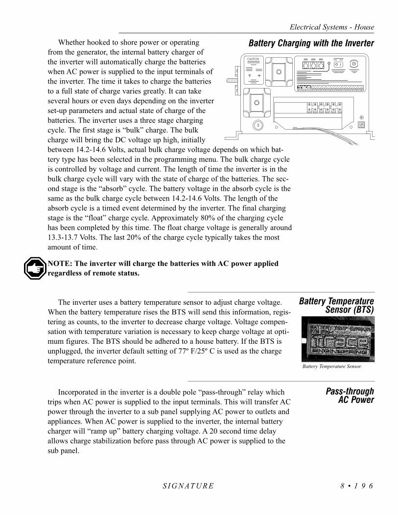
Whether hooked to shore power or operatingfrom the generator, the internal battery charger ofthe inverter will automatically charge the batterieswhen AC power is supplied to the input terminals ofthe inverter. The time it takes to charge the batteriesto a full state of charge varies greatly. It can takeseveral hours or even days depending on the inverterset-up parameters and actual state of charge of thebatteries. The inverter uses a three stage chargingcycle. The first stage is “bulk” charge. The bulkcharge will bring the DC voltage up high, initiallybetween 14.2-14.6 Volts, actual bulk charge voltage depends on which bat-tery type has been selected in the programming menu. The bulk charge cycleis controlled by voltage and current. The length of time the inverter is in thebulk charge cycle will vary with the state of charge of the batteries. The sec-ond stage is the “absorb” cycle. The battery voltage in the absorb cycle is thesame as the bulk charge cycle between 14.2-14.6 Volts. The length of theabsorb cycle is a timed event determined by the inverter. The final chargingstage is the “float” charge cycle. Approximately 80% of the charging cyclehas been completed by this time. The float charge voltage is generally around13.3-13.7 Volts. The last 20% of the charge cycle typically takes the mostamount of time.
NOTE: The inverter will charge the batteries with AC power appliedregardless of remote status.
The inverter uses a battery temperature sensor to adjust charge voltage.When the battery temperature rises the BTS will send this information, regis-tering as counts, to the inverter to decrease charge voltage. Voltage compen-sation with temperature variation is necessary to keep charge voltage at opti-mum figures. The BTS should be adhered to a house battery. If the BTS isunplugged, the inverter default setting of 77º F/25º C is used as the chargetemperature reference point.
Incorporated in the inverter is a double pole “pass-through” relay whichtrips when AC power is supplied to the input terminals. This will transfer ACpower through the inverter to a sub panel supplying AC power to outlets andappliances. When AC power is supplied to the inverter, the internal batterycharger will “ramp up” battery charging voltage. A 20 second time delayallows charge stabilization before pass through AC power is supplied to thesub panel.
Electrical Systems - House------------------------------------------------------------------------------------------------------------------------------------------------------------------------------------------------------------------------------------------------------------------------------------------------------------------
S I G N AT U R E 8 • 1 9 6
Battery Charging with the Inverter
Battery TemperatureSensor (BTS)
Pass-through AC Power
Battery Temperature Sensor.

This field is a general overview of system status. This is the primary screenof the RC7 remote. This field area includes:
Main Menu• Waiting for AC: System inactive waiting
for AC power to be supplied.• Inverting: Unit is inverting.• Charging Cycle Status: Bulk, Absorb or
Float mode.• Battery State of Charge: Based on the Fuel
Gauge Cutout setting. It may be displayed in percentages or as a fuel gauge.
• Time Left To Run: This evaluates the battery reserve capacity at current operating load. It is based on the Fuel Gauge Cutout and Battery Bank Capacity settings.
• Time Left To Charge: Estimated time left tocharge batteries to full state of charge. This is based on Fuel Gauge Cutout and Battery Bank Capacity settings with current battery voltage.
• Generator Start/Stop: Use inverter ON/OFFbutton to remotely start the generator or to override automatic generator start feature for manual operation. This feature is available to use without altering automaticgenerator start programming.
This is an alternate field of main system status. To access the various metersavailable, depress the UP arrow button and hold for five seconds. The RC7 GSremote will beep. Release the button. The Avg Shunt Amps will be displayed.This field area includes:
Avg Shunt Amps: This measures the DC current either charging ordischarging. Most of the house DC current usage is monitored bythe inverter.
Battery Voltage: This monitors the house battery voltage.
Inv/Chg Current: This measures the AC current usage when theinverter is charging.
Inverter Output VAC: This monitors the AC output voltage whilethe unit is inverting.
Electrical Systems - House---------------------------------------------------------------------------------------------------------------------------------------------------------------------------------------------------------------------------------------------------------------------------------------------------------------------
S I G N AT U R E8 • 1 9 7
Operating Display
Meter Menu

AC Input Amps: The inverter uses a double pole pass through relay.This measures current consumption through the Hot 1 terminal.
Battery Temperature: This monitors counts of the battery temperaturesensor (BTS). Counts are measured impulses which the inverter usesto calculate the battery case temperature. The charging voltage isadjusted to optimum values.
Xformer Temp: This monitors the transformer temperature which ismeasured in counts. Higher count readings are registering lower tem-peratures.
FET Temp: This monitors the Field Effect Transistor temperaturewhich is measured in counts.
Est Batt Cap: This estimates the battery bank capacity in amp hours(Ahrs). Charging and discharging on a cyclic basis will give anapproximate indication of the battery capacity in amp hours. Observethe reading and multiply by eight to obtain an approximate reservecapacity. This figure is only approximate and will change with cyclicuse.
To enter programming mode:• Press and hold the Set-Up buttons (up and down arrows) for five sec-
onds. The RC7 GS remote will beep. • Release the buttons. The programming mode has been entered when
the Search Sense is displayed. • Use the Menu buttons (up and down arrows) to scroll though available
field settings.• Use the Settings button (arrow pointing to right) to scroll through avail-
able settings for selected field.
To exit the programming mode: • Allow 20 seconds to elapse from the time the last key is pressed.
Program changes are then accepted by the inverter in non-volatilememory.
• Momentarily pressing the set-up buttons (up and down arrows) exits theprogramming menu. Program changes are automatically saved in non-volatile memory.
• The inverter is now ready to use. “Waiting for AC” will be displayed orif any program changes were made with AC applied, one of the threestages of the charge cycle will be displayed.
Electrical Systems - House------------------------------------------------------------------------------------------------------------------------------------------------------------------------------------------------------------------------------------------------------------------------------------------------------------------
S I G N AT U R E 8 • 1 9 8
Programming the RC 7 GS

NOTE: All electric coaches use two remotes and two inverters. Theremote located in the monitor panel is used to program the masterinverter. The second remote displays only selected menu items.
NOTE: Non-volatile memory is a permanent programming changeaccepted by the inverter. Turning the main battery disconnect switchesoff does not affect programming changes. Only the inverter clock timeand automatic generator start/stop programming will be erased.
Search Sense:The inverter searches for an AC load. For example: While inverting, AC
loads of various amperage may be applied. These loads may range from afew watts to several amps. Search Sense is the cut-in point which the invert-er will exit the “sleep mode” and start inverting at a standard output voltage.The Defeat setting allows the inverter to be at a constant standard outputvoltage. When changing the Search Sense value AC loads must be evaluatedfor proper inverter operation.
Auto LBCO:The Automatic Low Battery Cut-off may be turned on or off. These set-
tings allow the inverter to use available DC voltage to a set value whileinverting. Turning the LBCO ON stops the inverter when the battery voltagedrops to 10.5 Volts DC. Turning the LBCO OFF stops the inverter when thebattery voltage drops to 8.5 Volts DC. This leaves the batteries discharged,but not completely dead.
Battery Capacity:The battery bank capacity is adjustable in Ahrs (amp hours). These set-
tings change charging curves and the length of time of the charging cycles.The range is from 125 Ahrs to 1,000 Ahrs. Select the closest Amp Hour rat-ing for the house battery bank capacity. The auto setting will “learn” the bat-tery bank size by user characteristics. For example: Discharging and recharg-ing the batteries on a cyclic basis. The inverter takes several charging cyclesto “learn” an individual battery bank size. When the main battery disconnectshave been tuned off, the “learning” curve is erased.
Battery Type:Many types of batteries with different chemical compositions are avail-
able. Different chemical types require different charging characteristics atdifferent voltages. Selection of available battery types are:
• AGM (absorb glass matte) • Gel Cell • Liquid Lead Acid
Electrical Systems - House---------------------------------------------------------------------------------------------------------------------------------------------------------------------------------------------------------------------------------------------------------------------------------------------------------------------
S I G N AT U R E8 • 1 9 9
Adjustable FieldSettings

Charge Rate:Charge rate is adjustable from 10 to 100%. This feature may be used in many
different ways. Selecting a lower percentage charge rate lowers the inverter AC bat-tery charger’s current consumption. It will take longer to charge batteries but willleave user a few extra AC amps when operating from a limited AC power source.
Shore Power Amps:This is a load shedding feature of the battery charger in the inverter. For exam-
ple: Shore Power Amps set to 30 amps will decrease the AC current available forthe internal battery charger’s use, as pass through AC current value approaches 30amps. Lowering shore power amps will limit the available AC current for the inter-nal battery charger’s use. This is adjustable from 5 to 30 amps, in 5 amp incre-ments.
RC7 GS Setup:This option allows the user to select the desired screen display. The Last Key
will leave the menu active with the last status viewed on the display. The RollingDisplay will continue to scroll through the active menu status display. Power Saverallows the display to “sleep” after viewing the status. Touch any key to “awaken”the RC7GS remote, then press the desired key.
LCD Contrast:This changes the display screen contrast. Six settings are available. Lighter con-
trast settings may leave the screen difficult to see in a bright atmosphere.
External Shunt:The inverter monitors both AC and DC current values, whether charging or dis-
charging (figures are approximate), by using internal or external shunts. A shuntmonitors partial current consumption, allowing the majority of current to pass onheavier conductors. Programming shunt selection affects which shunt the inverter isusing to monitor DC current values. Single inverter systems use their internal shuntto monitor system DC current values. When programming single inverter systemsselect External Shunt None. Dual inverter systems use an external shunt to monitorsystem current values. When programming the shunt selection of a dual invertersystem, the master inverter is programmed by the remote installed in the monitorpanel. The master inverter will be programmed as External Shunt This Inverter. Theslave inverter will be programmed as External Shunt Other Inverter.
Fuel Gauge Cutout:Battery chemistries and types have different static voltage readings at
different states of charge. The battery voltage may be used to determine an approxi-mate state of charge for that battery type and chemistry. The Fuel Gauge Cutoutvoltage is a reference point the inverter uses to determine a battery with no reservecapacity amp hours remaining. Changing the value of the Fuel Gauge Cutout will
Electrical Systems - House------------------------------------------------------------------------------------------------------------------------------------------------------------------------------------------------------------------------------------------------------------------------------------------------------------------
S I G N AT U R E 8 • 2 0 0

affect the fuel meter, automatic generator start and stop points if set by SOC(state of charge) and time left to run or charge. The Fuel Gauge will read 0when the Fuel Gauge Cutout pre-programmed voltage reaches 50% SOC.
NOTE: The remaining field items are used to program the AutomaticGenerator Start parameters.
The house batteries operate most of the interior lighting and most appliances. As the house battery power is consumed the reserve battery capacitydiminishes. The inverter can be programmed to automatically start and stop thegenerator to keep up with the drain on the house batteries. All field referencepoints are house battery indications or conditions. A wide field of parametersmay be chosen for the generator start and stop points. These points may be setin three categories:
1. House battery voltage.2. State of charge (SOC). The Fuel Gauge Cut-out affects SOC.3. Absorb or Float point of the charge cycle.
For example: The inverter can be programmed to start the generator whenhouse battery voltage falls to 11.4 Volts. As the battery voltage rises the inverter can be programmed to stop the generator when the house battery voltage obtains a percentage of state of charge (SOC). When selecting the fieldreference points make sure that the start and stop points are spread apart.
It is possible to set parameters too close, causing short cycling of the generator. The menu will display the status of the generator while pending generator start. The generator must be operating correctly for proper automaticgenerator start and stop operation.
NOTE: If the generator is started manually from any remote switchother than the RC7 GS remote while automatic generator start fea-ture is enabled, the generator will shut down due to field parametersettings.
To override the automatic generator operation so that the generator may beoperated manually, use the RC7 GS remote Inverter button to start or stop the generator. This is done using the UP or DOWN arrows while in the main menuuntil Generator Start/Stop: Press (on/off) is displayed. The display will informthe user of the generator’s status. The generator will need to be manuallystopped.
Electrical Systems - House---------------------------------------------------------------------------------------------------------------------------------------------------------------------------------------------------------------------------------------------------------------------------------------------------------------------
S I G N AT U R E8 • 2 0 1
AutomaticGenerator Start

To enable the automatic generator operation, the programming mode mustbe entered. Before any field reference points can be established the clockmust first be set. The clock set field is the last item in the programmingmenu.
Clock Set:The clock is a 24 hour clock. If the display reads 00:01, it is 12:01 a.m.
If the clock reads 13:00, it is 1:00 p.m. The hours and minutes will flash, alternating every eight seconds. Use the Settings button to advance hours orminutes. The clock time and the generator start/stop programming willbe erased whenever the main battery disconnects are turned off.
Generator Start:Selecting a state of charge (SOC) generator start point is affected by the
Fuel Gauge Cutout voltage setting. SOC start points are between 40-60 per-cent, or the generator may be programmed to start at a specified voltage. Themanual start disables the automatic start.
Generator Stop:Selecting a state of charge generator stop point is affected by the Fuel
Gauge Cutout voltage setting. SOC stop points are between 90-99 percent, orthe generator may be programmed to stop at the Absorb or Float point ofcharge cycle. The manual off disables the automatic stop.
Begin Generator Quiet Time or End Generator Quiet Time:The automatic generator start feature may be programmed to operate only
at certain times in the 24 hour clock period. Example: The user wants theautomatic generator to start operation at 10:00 a.m. and stop operation at7:00 p.m.
End Generator Quiet Time:This is the time which the automatic generator operation is to begin.
Using the example time above, the 24 hour clock would be set to 10.00 hrs.
Begin Generator Quiet Time:This is the time which the automatic generator operation is set to stop.
Using the example time above as a reference, the 24 clock would be set to 19:00 hrs.
NOTE: If the generator started from the automatic start programand has not reached the automatic stop set point when quiet timebegins, the generator will stop and “Gen Quiet Fault” will be dis-played.
Electrical Systems - House------------------------------------------------------------------------------------------------------------------------------------------------------------------------------------------------------------------------------------------------------------------------------------------------------------------
S I G N AT U R E 8 • 2 0 2

Select Generator:The inverter has the capability to operate more than one generator
manufacturer type. The selections are:• Onan Quiet Diesel (Type used in Monaco Coach).• Power Tech, two and three wire.• Other 30-80 (reserved for future).
To disable the automatic generator operation use one of the following methods: • Set Generator Start and Generator Stop points back to manual
ON/OFF positions.• Switch off the house and chassis main battery disconnects to erase the
clock time and generator start/stop programming.
Batteries can sulfate over time. When this occurs some of the sulfuric acidhas adhered to the lead plates of the battery and cannot enter the electrolytesolution though normal battery charging. A battery with a low concentration ofacid in the electrolyte will effect the battery’s performance. Sulfation can occurwhen a battery is stored in a discharged condition or when a battery is continu-ally cycled below a 50% state of charge. An indication a battery has sulfated iswhen the inverter is in float charge and the hydrometer reading has stabilizedbelow a full state of charge (approximately 1260). An equalize charge cyclemay promote the acid to leave the lead plate and enter the electrolyte solution.This is done by charging the battery at a slightly higher than normal voltage fora short duration. The equalization cycle will charge the batteries at approxi-mately 15.5 volts for three hours. To maximize the results from an equalizecharge initiate the equalize cycle after the batteries have entered float charge.Only liquid lead acid or absorb glass matte (AGM) type batteries should beequalize charged. Other battery types can be damaged if equalize charged.Monitor the electrolyte solution closely when equalizing a liquid lead acid bat-tery. A battery’s “healthy” cell(s) can be damaged if overcharged. High DCcharge voltages can also damage voltage sensitive electronic equipment.Several precautions should be used when performing an equalize charge:
• Only equalize charge batteries with the motorhome in a well ven-tilated area, preferably outdoors. Liquid lead acid batteries pro-duce explosive hydrogen gas when charging. Extinguish allflames and other sources of ignition.
• Secure the battery compartment door in the open position. Extendbattery trays to the full open position when equalize charging.
• Remove the liquid lead acid battery caps during the equalizecharge cycle. AGM battery caps are not removable and may voidthe battery’s warranty if removed.
• A liquid lead acid battery will consume water at an equalize
Electrical Systems - House---------------------------------------------------------------------------------------------------------------------------------------------------------------------------------------------------------------------------------------------------------------------------------------------------------------------
S I G N AT U R E8 • 2 0 3
Equalize Charging
charge voltage. Fill battery cells with distilled water before beginning anequalize charge cycle. Do not overfill the battery cells. Overfilled batterycells will spatter excess electrolyte.
• Protect all painted surfaces from any electrolyte solution which may spat-ter during equalize charging. If the electrolyte solution spatters on theexterior painted surface rinse immediately using large quantities of water.
• Turn OFF the battery cut-off switch located at the entry door. • Remove the fuses from the solar panel charge leads.• Observing the polarity, disconnect the 12 Volt DC supply from the refrig-
erator. Access supply leads through the outside refrigerator compartment.Tape the positive lead to prevent a short circuit.
• Mark the specific location then disconnect the wires from the batterymaintainer.
• Avoid operating any electrical equipment while in the equalize chargecycle.
To Equalize Charge:• Press and hold the Settings button on the remote (arrow pointing right) for
six seconds. Charge light will flash rapidly and System Status: Equalizewill appear on the screen. The inverter will run the equalize charge cyclefor three hours.
To Exit Equalize Charge:• The equalize charge cycle may be discontinued at any time during the
charge cycle. Press and hold the settings button for six seconds. Theinverter will display System Status: Absorb for thirty seconds then switchto float charge.
• Allow the batteries to cool for approximately three hours. Check the elec-trolyte solution with a hydrometer. Avoid overcharging the battery result-ing in damage to the healthy cells.
• Add distilled water if necessary. Install battery caps. Use large quantitiesof fresh water to rinse the entire battery compartment and surroundingarea.
• Install fuses to solar panel charge leads.• Observing polarity, hook the 12 Volt DC supply leads to the back of the
refrigerator. Do not reverse polarity. Damage to the refrigerator circuitboard can result.
• Hook up the battery maintainer. Be sure the wires are connected to thecorrect location.
CAUTION: Never equalize charge a frozen battery.
WARNING: Liquid lead acid batteries produce highly explosive hydro-gen gas when being charged. Extinguish all flames and other sources ofignition. Never smoke around batteries. Danger of explosion, fire, prop-erty damage, serious personal injury or death can result!
Electrical Systems - House------------------------------------------------------------------------------------------------------------------------------------------------------------------------------------------------------------------------------------------------------------------------------------------------------------------
S I G N AT U R E 8 • 2 0 4

The remote is used to program or turn on or off the inverter. The RC7 GSremote is a display only. All the programming information is retained in theinverter. If the inverter exhibits unusual symptoms or behavior such as notresponding to commands or displaying erroneous error conditions, “re-booting” the inverter may alleviate these symptoms.
To re-boot the inverter:1. Remove AC power from the inverter by disconnecting shore power
and/or shutting the generator off.2. Turn the main switch on the inverter to the OFF position.3. Switch house and chassis main battery disconnects to the OFF position.4. Wait 30 seconds, this allows time for capacitors to discharge.5. Switch house and chassis main battery disconnects to the ON position.6. Turn the main switch on the inverter to the ON position.7. Connect the shore power cord or start the generator.
The AC distribution panelsare located in the bedroom. Themain 120 Volt AC panelreceives power from the trans-fer switch, which is supplied byeither shore power or the gener-ator. The AC power is suppliedto the 50 amp main breakerfirst, then the power is suppliedto the individual branch circuitbreakers. The panel labeldescribes the breaker layout andthe item, outlet or appliance towhich they pertain. The subpanel receives AC power fromthe inverter. The sub panel sup-plies power to items which canbe operated by the inverter.When operating from eithershore power or the generator,the sub panel is automaticallysupplied with AC power fromthe pass through relay in theinverter. When hooked to shorepower or operating from thegenerator, the AC power goes tothe main AC panel first. The
Electrical Systems - House---------------------------------------------------------------------------------------------------------------------------------------------------------------------------------------------------------------------------------------------------------------------------------------------------------------------
S I G N AT U R E8 • 2 0 5
Re-booting theInverter
DISTRIBUTION PANEL - HOUSE 110AC Panel
FRONT A/C
REAR A/C 20 2
INVERTER (L2) 30 3
INVERTER (L1) 30 6
BLOCK HEATER 15 7 (GFI)
.WASHER/DRYER 20 8AWATER HEATERAQUA HOT - OPT 20 8B
20 1
MAIN 50
4
5
Main Panel.

branch circuit breakers in the main panel then supply AC power to the inputterminals of the inverter. The pass through relay inside the inverter trips sup-plying AC power to the sub panel.
When using the inverter as the AC power source, the pass through relay isnormally closed. The AC power produced by the inverter supplies power tothe sub panel only.
WARNING: The 120 Volt AC panels contain high voltage which cancause serious injury or death. Before beginning any work or testing pro-cedures involving the electric panels, or any of the branch circuits, besure the motorhome is unplugged from shore power, the generator is notrunning and the inverter is in the off position. Certain testing proceduresmay require the AC power to be on. Only qualified personnel or person-nel with electrical backgrounds should attempt any testing procedures.
Branch circuit breakers supply AC power to the different items or“loads.” An electrical load is any item or device that will use current whensupplied with an electromotive force. Should a breaker “trip” from over cur-rent use, or a short circuit condition, the load should be tested or disconnect-ed to determine the reason the breaker tripped. If no cause is found, or notreadily apparent, reset the breaker by toggling the breaker to the OFF posi-tion, then back to ON. Should the breaker trip again after the load is reap-plied it may indicate a fault with that particular load. Do not continue to resetbreaker until the problem has been correctly diagnosed and corrected.
Electrical Systems - House------------------------------------------------------------------------------------------------------------------------------------------------------------------------------------------------------------------------------------------------------------------------------------------------------------------
S I G N AT U R E 8 • 2 0 6
FRONT,KITCHEN (GFI) 20 2
INVERTER (L2) 30 3
MICROWAVE 20 4
REFER 20 5
INVERTER (L1) 30 6
BATH, REAR (GFI) 20 7
LAMP TABLE ARMREST, POWER 20 8CURTAIN (OPT) (GFI)
1
Inverter Panel.

Breaker current ratings are current set points in which the breaker isdesigned to operate. The internal configuration of the circuit breaker is designedto trip when excess current is drawn through the breaker. The breaker will heatup from the excess current causing the breaker to trip. The trip action of the circuit breaker can occur within milliseconds due to the speed at which electric-ity can travel. Breakers are designed to operate at a continuous load of 80% ofthe breaker’s rated capacity. For example: A breaker with a 20 amp rating willoperate a continuous 16 amp load. This design leaves a small amount of work-ing capacity within the breaker. When an inductive load is applied, such aswhen an electric motor turns on, the motor starts to spin and current consump-tion may momentarily exceed the rated capacity of the breaker. As the electricmotor comes up to operating speed, the electric motor’s current consumptionwill fall. The AC current load then falls back into the breaker’s rated 80% setpoint. This electric principle should be kept in mind when using anything otherthan 50 amp shore service and using appliances with electric motors, such as airconditioners. When using outlets, care should be considered when applyingloads such as electric motors, heaters, coffee makers, toasters, hair dryers orother large current consuming loads. The current rating is usually stated onmost electrical items. The current rating will either be rated in amps or watts.Current ratings stated on electrical items will change slightly with voltage fluc-tuations. As voltage increases current consumption decreases. As voltagedecreases current consumption increases. This may explain why in someinstances items operated at borderline voltage to current tolerances may seemfine in one location but problematic in another.
NOTE: To calculate watts to amps simply divide the watt figure by the voltage of which the item operates from. For example: Theelectrical item is rated at 1,370 watts. Divide that by the operatingvoltage of 115 volts which equals 11.913 amps. Use this formula tocalculate the amount of load to the available power supply.
A ground fault circuit interrupter “GFCI” can be found in two differenttypes of applications. One type is incorporated in a breaker used in 120 volt ACbreaker panels, the other is incorporated in an outlet. The GFCI, whether it is abreaker or an outlet, offer two types of protection. One type of protection isfrom over-current or shorts. It also provides protection for persons against haz-ardous ground fault currents which can result in injury or death. Ground faultcurrents are currents that flow from the “HOT” or power terminal through aperson to the ground. For example, touching a faulty appliance while standingon or making contact with an electrical ground such as a water fixture, bath tubor the earth. If the device has been properly installed it will offer protectionagainst the type of shock that can result from faulty insulation, wet wiring frominside an appliance, or any device or equipment plugged in or wired to that cir-cuit. The “ground fault” portion of the outlet or breaker uses sensitive electron-
Electrical Systems - House---------------------------------------------------------------------------------------------------------------------------------------------------------------------------------------------------------------------------------------------------------------------------------------------------------------------
S I G N AT U R E8 • 2 0 7
Circuit Breaker
GFCI BREAKERS & OUTLETS
GFCI Outlet.

ics inside the outlet or breaker to detect a ground fault problem. The elec-tronics monitor the normal current of power, flowing to the “hot” or blackwire through the load (eg. a light bulb or appliance) and coming back on the“neutral” or white wire. If just a small amount of the current comes back onthe safety ground wire the electronics will “trip” the breaker or outlet, stop-ping the flow of electricity. The amount of current it takes to trip the devicefrom a ground fault varies slightly from the different outlet or breaker manu-facturers (approximately 30 mils or less). Electrical shocks resulting fromground faults can be felt, but such a shock is considerably less than one with-out ground fault protection. People with heart conditions or other conditionsthat make them susceptible to shocks can still be seriously injured. A GFCIoutlet or breaker will not protect against shock from a normal current flow.For example, a shock from touching both metal prongs of an electrical cordor appliance while plugging it in.
WARNING: If a breaker or outlet trips continually DO NOT con-tinue to reset breaker or outlet until the problem has been identi-fied and corrected.
NOTE: The ground fault outlet or breaker should be tested once amonth to insure it is working properly. Use the “TEST” button onthe outlet or breaker. It should trip with an audible “click.” Thebreaker or outlet will not trip if no AC power is present to thedevice. If power is present and the device will not “trip,” replace itbefore using that circuit.
NOTE: One mil is 1/1000 of one amp.
The 12 Volt DC house distribution panel contains fuses (locat-ed in the bedroom overhead cabinet) that protect the electrical cir-cuits. These fuses are a standard automotive type. When a fuse is“blown,” the wire in middle of the plastic case will be burnt. Abroken, bad or “blown” fuse must be replaced with a fuse of thesame rating and type. Using a fuse with a different rating or typewill defeat the circuit protection provided by that fuse and couldresult in damage to the motorhome’s electrical system.
Electrical Systems - House------------------------------------------------------------------------------------------------------------------------------------------------------------------------------------------------------------------------------------------------------------------------------------------------------------------
S I G N AT U R E 8 • 2 0 8
Fuse Panel Label
DISTRIBUTIONPANEL - HOUSE 12 VOLT

The 12 Volt fuses, located in this distribution panel, service the interiorhouse lighting, ventilation fans and monitor panel. Should a fuse blow it will beevident by the broken metal strip located in the center of the fuse. Replacementfuses should be of the same amperage. If a higher rated fuse is installed it candamage the wiring. Fuse current set points follow much of the same electricalprinciple as the 120 Volt AC breakers. Using 12 Volt DC as the electromotiveforce can make it more susceptible to outside influences, such as corrosion fromweathering or oxidation.
The large variety of applications this voltage is used for makes it commonfor most of the recreational vehicle and automotive industries. The danger fromshocks with this voltage is minimized, but can still occur. A good example ofthis is when a magnetic field is generated, then collapses when the power sup-ply is turned off. The result is an electrical discharge that can reach tens ofthousands of volts for a short time period. Care should be used when workingwith this voltage as current values can be quite high, as in the case of a batterycables.
Shorting a battery cable to ground with a battery at a reasonable state ofcharge can result in a fire or serious personal injury from a burn.
Electrical Systems - House---------------------------------------------------------------------------------------------------------------------------------------------------------------------------------------------------------------------------------------------------------------------------------------------------------------------
S I G N AT U R E8 • 2 0 9
Fuses
Amperage Chart.
ATO Fuse

One of the most widely used tools used for testing a 12 Volt problem isthe test light. Many different types of test lights are available such as a lightbulb with a probe and ground clip, to the more elaborate electronic ones thatmeasure a wide scale of voltages and perform a variety of functions. A VOMor Volt Ohm Meter is used to perform a multitude of tests. It is generallyused when exact values are needed for evaluation. These meters come in ananalog or digital format. Either of these two testing tools may be used,depending upon personal preference. If a 12 Volt light is not working the testlight may be better suited for this. In the event of a charging system prob-lem, where exact voltage values need to be obtained, the meter may be thetool of choice. In any situation the testing tool is an invaluable piece ofequipment when it comes to determining an electrical problem.
Should it become necessary to use testing tools, take certain precautionsand consider three things. First, recognize when the problem is beyond yourskill level. Nothing will create more mayhem than being armed with toolsand going in an unknown direction. Good intentions may lead to major prob-lems. The second item to keep in mind is if something will cause more griefby being dealt with now, than if it were left alone and repaired by a profes-sional at a more convenient time. How many times have you said to your-self, “Oh this will only take a few minutes,” only to find it is taking an entireday and you wished you had not touched it. The third item to consider iswhether or not the current situation may become potentially dangerous if leftto be repaired at a more convenient time?
NOTE: Check all related fuses before assuming you have encoun-tered an electrical problem or situation. Spare fuses should be kepton hand, and can be purchased from auto parts stores. A fusedescription label is on the distribution panel cover.
WARNING: If a fuse blows, replace the fuse with same amperagerating and type. Installing higher amperage fuses can damage thewiring or the item the fuse is protecting, or may cause a fire. If thefuse repeatedly blows after replacing it, do not continue to replaceit. Have the problem diagnosed and corrected by a qualified tech-nician.
Electrical Systems - House------------------------------------------------------------------------------------------------------------------------------------------------------------------------------------------------------------------------------------------------------------------------------------------------------------------
S I G N AT U R E 8 • 2 1 0
Tools of the Trade
Knowing When toSay When

Batteries come in different sizes, types, amp hours, voltages andchemistries. There are nearly as many descriptions of battery types and howthey should be used as there are people willing to offer advice on them.Although it is not possible to cover batteries in their entirety, there are guide-lines that can be followed to ensure that the batteries are well maintained.
The operation of the battery is based on a chemical reaction. The batteryis a container of lead plates, insulators and a solution of distilled water andsulfuric acid. The solution, when mixed together, is known as “electrolyte.”The 12 volt battery is actually six batteries in one case. When charged, eachcell has a voltage of 2.1 Volts. When six cells are hooked together this makesa 12.6 Volt battery (fully charged).
Electrons are stored on the negative plates. When a load (eg. a light bulb)is put between the positive and negative terminals, the electrons move fromthe negative plate to the positive plate through the “load” and then back tothe ground terminal. At this time the sulfuric acid leaves the water andadheres onto the plates of the battery. The electrolyte solution keeps the elec-trons from flowing while the battery is in the “at rest” position.
Charging the battery moves the sulfuric acid back into solution with the distilled water. A battery left in a low or discharged state will cause the acidto “sulphate.” In attempting to recharge the battery, the acid has becomehardened and no longer will leave the plates and enter into the liquid solutionwith the distilled water. The lowered acid to water ratio has a direct affect onthe battery’s ability to release the stored electrons (power output) and thelength of time it can perform (reserve capacity). Batteries left in a dischargedcondition will readily freeze. This can crack the case allowing the solution tospill, it can also warp the plates. The acid acts like an “antifreeze” for thebattery. This is why batteries should not be left or stored in a “discharged”condition.
Starting batteries are designed for high output cranking power, but not fordeep cycling like the house batteries are designed to do. Starting batterieswill not last long in deep cycle application. The way they are rated shouldgive a good indication of their intended use. “Cold Cranking Ampere” is ameasurement of amperage output that can be sustained for 30 seconds.Starting batteries use thin plates to maximize the surface area of the battery.This allows a very high starting current but lets the plates warp when the bat-tery is deep cycled (discharged).
Electrical Systems - House---------------------------------------------------------------------------------------------------------------------------------------------------------------------------------------------------------------------------------------------------------------------------------------------------------------------
S I G N AT U R E8 • 2 1 1
BATTERY - HOW IT WORKS
Starting Battery

Deep cycle batteries are best suited for use with 12 volt operated lights,appliances and inverters. Deep cycle batteries are designed to have a majorityof their capacity used before being recharged. These are available in manysizes and types. The most common is a non-sealed, liquid electrolyte battery.The non-sealed types have battery caps. The caps should be removed periodi-cally to check the level of electrolyte. When a cell is low, only distilled watershould be added. Water consumption will vary depending on many factors:how far the batteries are depleted, how long the voltage is being applied tocharge the batteries, how much voltage is used and how often this occurs.
NOTE: Tap water contains minerals which can alter batterychemistry and ruin the battery. Use only distilled water when refill-ing the battery.
At a minimum, the battery electrolyte level should bechecked at least once a month. Check the level sooner if the battery is frequently used. The level should be above the top of the plates, but not overfull. Most batteries have a plasticcup or well. The electrolyte level should be approximately3/8” below the well to allow room for expansion while thebattery is being charged. Over-filling the battery will allow theelectrolyte solution to boil or gas out of the battery cap.Remember to use only distilled water to refill the battery. Abattery with a low electrolyte level will boil the water out rap-idly once the plates have been exposed to air. This processmay take only a matter of hours. If this has happened the bat-tery is more than likely damaged.
After checking the battery’s electrolyte levels it is also agood idea to check the battery connections for tightness andcorrosion. If any corrosion is found disconnect the cables(make sure to mark their locations) and carefully clean themwith a mild solution of baking soda and water. There are alsoaerosol products available that will work. This will neutralizeany acid that may be present. Do not allow the solution toenter the battery as this will damage the electrolyte balance.Use water to rinse the top of the battery and surrounding area when done.Carefully hook the cables back to the battery. Coat the terminals with petro-leum jelly or an anticorrsion grease.
The battery cable to battery terminal connections should be metal tometal. Periodically check the batteries for corrosion. Look for cracks andcheck the vent plugs. Replace them if they are cracked or missing. Keep thetop of the batteries clean. The accumulation of electrolyte and dirt may per-mit small amounts of current to flow between the terminals, which can drainthe battery.
Electrical Systems - House------------------------------------------------------------------------------------------------------------------------------------------------------------------------------------------------------------------------------------------------------------------------------------------------------------------
S I G N AT U R E 8 • 2 1 2
Deep Cycle Battery
Battery Maintenance
The Chassis Battery (1) and the Domestic Batteries ( 2),located within the Battery Storage Compartment.
2
1

WARNING: Liquid lead acid batteries produce hydrogen gas whilebeing charged. This is highly explosive. Do not smoke around batter-ies. Extinguish all flames in the area. The hydrogen gas may exploderesulting in fire, personal injury, property damage or death.
The engine (chassis) and domestic (house) batteries are located in a curbsidecompartment. The slide-out battery trays are secured in place by a lockingmechanism at the front of the trays. To slide the tray out, lift up on the handleand pull until the tray stops. To secure the battery tray, push it back in until thetray latches.
The battery tray slides will occasionally need to be lubricated. When per-forming maintenance to the batteries clean the old lubricant and dirt from thebattery tray slide with solvent, brake cleaner or equivalent. Do not allow any ofthe cleaning solution or battery acid by-products to spatter onto the painted sur-faces. Damage to the paint surface will result. Lubricate all moving parts of thebattery tray slide with white lithium grease or Kwikee brand spray lubricant.
NOTE: Driving without the tray secured can result in damages.
CAUTION: Many types of petroleum based products or battery by-products can damage the paint finish. Do not allow these types ofchemicals to get on the paint finish. If the chemicals do get on thepainted surfaces immediately rinse the surface using plenty of waterwith a mild automotive detergent.
The only way to test a battery’s electrolyte solution is with a hydrometer.Many styles are available, from types with cylinder graduation (shown here) totypes with floating balls. Hydrometers can be purchased from most auto partsstores. The hydrometer tests the battery’s electrolyte solution which is measuredin specific gravity. Distilled water has a specific assigned gravity of 1,000. Thehydrometer is calibrated to this mark. Pure sulfuric acid has a specific gravityreading of 1,840. The acid is 1.84 times heavier than water. The electrolytesolution is about 64% water to 36% acid (fully charged battery). Hydrometerswith cylinder graduation are graphed and the exact state of specific gravity canbe determined.
Temperature and recent battery activity (charging or discharging) affect thehydrometer readings. It is best to check the battery when it has been “at rest”for at least three hours, although readings taken at other times will give a “ballpark” figure. When using the hydrometer, draw the electrolyte solution up intothe tube. Allow the hydrometer to attain the same temperature as the electrolytesolution. Note the reading for that cell. Complete the same test for the rest of
Electrical Systems - House---------------------------------------------------------------------------------------------------------------------------------------------------------------------------------------------------------------------------------------------------------------------------------------------------------------------
S I G N AT U R E8 • 2 1 3
Battery Trays
Testing the Battery

the cells on that battery bank.The hydrometer is calibrated at 80° F. Temperature affects the
hydrometer readings. The higher the electrolyte temperature, the higherthe specific gravity reading. The lower the temperature, the lower thespecific gravity reading will be. Add or subtract four points for each 10°variance from the 80° F chart. Readings between cells should not varymore than 50 points.
If one cell in a particular battery bank being tested is at a 50% stateof charge while the others are indicating a full charge, charge only thatbattery to see if the low cell will come up. At the same time, do not overcharge the “healthy” cells.
If the low cell does not come up after charging, this battery can dam-age the rest of the battery bank and should be replaced. An accurate digi-tal volt meter + - .5% will also give an indicator of the battery’s state ofcharge.
Another test that can be performed is to place a specific load on thebattery for a predetermined length of time equal to that particular bat-tery’s rating. This machine is usually an adjustable carbon pile that canvary the load being applied to the battery(s) while monitoring voltage tosee if they will perform to their specific rated capacities
NOTE: See the chart for temperature compensation. Liquidlevels should be even between the cells of the battery being test-ed as it will affect the accuracy of the test.
WARNING: Sulfuric acid in the batteries can cause severeinjury or death. Sulfuric acid can cause permanent damage toeyes, burn skin and eat holes in clothing. Always wear splash-proof safety goggles when working around the battery. If the bat-tery electrolyte is splashed in the eyes or on skin, immediately flushthe affected area for 15 minutes with large quantities of cleanwater. In case of eye contact, seek immediate medical aid. Neveradd acid to a battery once the battery has been placed in service.Doing so may result in hazardous splattering of electrolyte.
Electrical Systems - House------------------------------------------------------------------------------------------------------------------------------------------------------------------------------------------------------------------------------------------------------------------------------------------------------------------
S I G N AT U R E 8 • 2 1 4
Hydrometer (Cylinder Type).
Temperature Correction Chart.
71.1� 160� + 32�� + 30 65.5� 150� + 28�� + 26 60.0� 140� + 24�� + 2254.4� 130� + 20�� + 18 48.9� 120� + 16�� + 14 43.3� 110� + 12�� + 10 37.8� 100� + 8�� + 6 32.2 � 90� + 4�� + 2 26.7 � 80� 0�� - 2 21.1� 70� - 4�� - 6 15.6� 60� - 8�� - 10 10� 50� - 12�� - 14 4.4� 40� - 16�� - 18 -1.1� 30� - 20�� - 22 -6.7� 20� - 24�� - 26-12.2� 10� - 28
FCorrection
FactorC�

1. Physical Condition:Active material flakes off the plates and falls to the bottom of the cell.
This is normal, but sediment accumulation under the plates can short out a cell.The plate separators fail to insulate positive and negative plates in a cell and thecell becomes shorted, ruining the battery.
2. Insufficient Electrolyte:This allows exposed portions of the plates to sulfate rapidly. This reduces
the battery’s ability to accept a charge and the battery capacity is reduced.Accelerated erosion of the lower portions of the plates occur from higher thannormal acid content due to water loss. Only the water evaporates, not the acid.The battery also has a higher internal resistance when low on water. Add onlydistilled water. Fill each cell to the bottom of the vent well when the battery iswarm. Filling a very cold battery with water to the bottom of the vent well willcause overspill when the battery warms up and the plates expand. A BatteryFormula For Failure: the battery has a higher internal resistance when low onwater, therefore: high resistance = more heat = shorter battery life!
3. Sulfation:When a battery remains discharged for too long the accumulated lead sul-
fate in the plate material solidifies and cannot reenter the electrolyte. When abattery is left in a discharged state the lead sulphate will crystalize. Chargingthe battery does not move the crystallized lead sulphate off the battery plate.The battery is damaged.
4. Overheating:The chemical reaction inside of the battery is increased when the battery
temperature rises above 125º F. This increases the corrosion of the plates andreduces the battery life. When overheated, the battery plates tend to buckle anddestroy the structural integrity of the battery.
5. Freezing:When the electrolyte freezes, ice formed dislodges the active material
from the plates. The battery case may crack and the electrolyte will leak outwhen thawed. It is especially important to keep a battery at full charge in coldweather to prevent freezing. The high specific gravity of a fully charged batterydoes not freeze as easily. Never attempt to charge a frozen battery. Warm it upfirst.
6. Corrosion:Corrosion from spilled or splashed electrolyte form deposits that can
conduct electricity and can cause battery drain. Clean off all corrosion, espe-cially around the battery terminals and on the top of the battery. Prevent accumulation by coating the terminals and the exposed metal cable connectorswith high temperature grease.
7. Overcharging:Overcharging rapidly converts water to gas and decreases the electrolyte’s
water content as the water evaporates. The electrolyte level drops and becomesmore acid in content. This subjects the plates to a higher concentration of sulfuric acid and results in early battery failure.
Electrical Systems - House---------------------------------------------------------------------------------------------------------------------------------------------------------------------------------------------------------------------------------------------------------------------------------------------------------------------
S I G N AT U R E8 • 2 1 5
Reasons WhyBatteries Fail

NOTE: Any time you add more than one or two ounces of distilled water per-cell per-thousand miles, check themotorhome charging system for overcharging. Prolongedovercharging generates excessive heat inside the battery,which buckles the plates and destroys the battery. It is a factthat over 50% of battery failures are caused by overcharging.
Why does the voltage on a discharged battery measure the same as a fullycharged battery until the loads are applied? The simple answer to this mightgo as follows: A battery creates electrical power by converting energy from achemical reaction into electrical energy. As this reaction slows down the bat-tery voltage will drop. In a lead acid battery the electrolyte conductivity (howwell electrical current can flow through it) changes. The same current may be available but the rate of the reaction decreases, causing a voltage drop.
Another way of looking at this is to use the analogy of a water pump (a battery is an electric pump). The pressure in PSI (pounds per square inch)that a pump delivers is like a battery’s voltage. The volume of water in GPM (gallons per minute) is like the electrical current. Let’s look at a 12 PSI pumpwith no loads (the pump is running but the outflow valve is turned off). Thepump will run and the internal pressure of the pump will build up to somepoint higher than 12 PSI. When the valve is opened, and the water is free toflow into the loads, the pressure will drop to the rated output pressure of 12PSI, but only if the load is not too big. If the pump is designed to maintain12 PSI at 15 GPM, and a load demanding 20 GPM is connected, the pumpwill not be able to keep up and the pressure will get sucked down to a lowerPSI. If the load is reduced or removed the pump will catch up and return toits rated 12 PSI pressure. If the pump has an infinite source of water, such asa lake or the water utility (this is like the grid, no battery), the pump willnever run out of pressure. If the pump never runs out of pressure, and isoperated at or below it’s 15 GPM level, it will hold 12 PSI. However, a pumpthat is connected to a water tank with a finite capacity will start to lose theability to hold pressure as the level of water in the tank drops. Think ofsiphoning water from a bucket. As the level of the water drops, the volumeof water exiting the siphon slows down.
When the tank is full it is capable of feeding more “pressure” to the pumpinlet due to gravity, and the pump always has enough water available to maintain its rated pressure and volume. However, if the water tank gets low the pump will not have enough water volume coming in to maintain 12 PSIat 15 GPM. If the loads are removed from the pump by closing the valve onthe outflow, even with low pressure in the tank the pump will eventuallypressure up to 12 PSI. It will just take it longer to get there. When the valveis opened the pump will sustain 12 PSI for a brief period, but since the tankis no longer feeding the pump as fast as needed the pressure will eventuallydrop. This analogy can be restated by replacing the pump with a battery,
Electrical Systems - House------------------------------------------------------------------------------------------------------------------------------------------------------------------------------------------------------------------------------------------------------------------------------------------------------------------
S I G N AT U R E 8 • 2 1 6
Battery Voltage &Current

pressure with voltage, volume with amps, outflow valve with a switch, waterwith electricity and the water tank with the battery electrolyte.
The level of the tank could be thought of as the rate of the reaction occur-ring in the electrolyte. When the battery is fully charged the electrolyte has anexcess of reactions taking place to feed the battery terminals. This tapers offwith time as the electrolyte is spent so maintaining voltage becomes possible.With no loads the discharged electrolyte will be capable of producing close tothe rated voltage, but only after a period of time has elapsed for enough of areaction to take place to bring the voltage back up. Hopefully, this explanationwill make clarify why a battery measured at rest can indicate close to its ratedvoltage but will not run a load.
Calculating Run Times: Calculating run time figures when operating 120Volt AC electrical items with an inverter can be exponential. This is due to bat-tery characteristics. Flow characteristics of electrons vary with different batterytypes and chemical compositions. Deep cycle batteries are generally designedto slowly release a majority of their charge capacity. Deep cycle batteries arerated in amp hours (Ahrs) with the discharge occurring over an extended periodof time before the battery is charged. Engine starting batteries are designed toquickly release large amounts of current for short durations, without depletingbattery reserves. Commercial type batteries bridge the gap of deep cycle andengine batteries. Commercial batteries release medium amounts of current overa longer period of time but they are not designed to cycle their charge capacity.
The working range of a deep cycle battery is between 50 and 100% state ofcharge (SOC). Deep cycle batteries should not be cycled below 50% state ofcharge. Discharging a deep cycle battery below 50% state of charge shortensthe life of the battery. Deep cycle batteries use an amp hour rating which is usu-ally calculated over a 20 hour discharge interval. Example: A deep cycle batterywith a rated capacity of 100 Ahrs. is designed to release current at the rate offive amps per hour. Multiply a 5 amp load over a 20 hour discharge periodequals the rated 100 Ahr. capacity. These discharge figures are calculated withthe battery starting at 100% state of charge with the battery at 80º Fahrenheitwhen the discharge cycle begins. However, increasing the discharge loadapplied to the battery from five amps to ten amps on a 100 Ahr battery does notyield 10 hours of discharge time. This is due to the internal reactions whichoccur when a battery is discharging. Actual discharge time for a 10 amp loadmay be closer to eight hours of discharge time. Increasing the load applied tothe battery to 20 amps will not yield five hours discharge time but may be lessthan three hours. It might be understood as a point of diminishing return.
Calculating applied loads to an inverter to approximate run time from thebattery amp hours available is not an equal trade up when voltage is invertedand amperage is calculated. When the inverter is used to operate an AC load ituses approximately ten times the DC current needed from the battery when
Electrical Systems - House---------------------------------------------------------------------------------------------------------------------------------------------------------------------------------------------------------------------------------------------------------------------------------------------------------------------
S I G N AT U R E8 • 2 1 7
Battery Charge Time& Consumption Rate

inverting 12 Volts to operate the 120 Volt item. There is also a small efficiencyloss of about 10% when inverting. For example: When using the inverter to oper-ate an AC electrical item, which has a current draw rating of 2 amps, the inverterwill use over 20 amps DC power from the batteries.
Determining Current Consumption: First determine the amount of currentused by an AC item. For example: The television is rated at 200 watts at 120Volts. Calculate watts to amps. Divide 200 watts by the operating voltage of 120,this equals 1.6 amps. Multiply 1.6 amps AC current by a factor of ten the inverterwill use, this equals 16 amps DC battery current. Add the revised 10% efficiencyloss figure, this calculates to a total of 17.6 amps DC. If the battery bank capacityis rated at 500 Ahrs., actual elapsed time to the suggested 50% state of chargewould net viewing time for the television at approximately 13 hours in ideal con-ditions.
The run time figure will vary greatly with the actual state of charge of the battery bank when the discharge process begins. Ambient temperature, com-bined with other working loads such as lights and parasitic loads applied to batter-ies, affect run times. Calculating the exact run time is not precise due to all thevariables and equations involved; however, an approximate time figure can be obtained. Proper battery maintenance and charge cycles affect bat-tery performance. Observe the battery condition with hydrometer and voltage readings. Use only distilled water when filling batteries. To achieve thehighest quality of battery performance and longevity keep batteries in their properoperating range.
Electrical Systems - House------------------------------------------------------------------------------------------------------------------------------------------------------------------------------------------------------------------------------------------------------------------------------------------------------------------
S I G N AT U R E 8 • 2 1 8
**Battery connections are made in a Series/Parallel connection.Domestic batteries are not rated in Cold Cranking Amps (CCA).
Battery Specifications
Ah(20hr)
240
225
255
CCA
950
**
**
RC(25A)min
.
450
447
25A - 46115A - 8018A - 16275A - 3130
Chassis12 Volt Chassis
31P-MHD (2 each)
6 Volt Domestic U2200 (4 each)
All ElectricBattery
SpecificationsGPL-8D (5 each)
STATE OF VS. OPEN CIRCUITCHARGE VOLTAGE
100% 12.66v75% 12.45v50% 12.24v25% 12.06v
Discharged 11.89v
STATE OF VS SPECIFICCHARGE GRAVITY
100% 1.26575% 1.22550% 1.19025% 1.155
Discharged 1.120

The motorhome comes pre-wired to accept this optional solar battery charging system. The system consists of one 90 watt solar panel with mounts, a combiner box (that allows you to easily expand the system) and a charge controller that can handle up to four 90 watt solar panels.
The Solar Panel:The Solar Panel is a Solec 90 watt panel that is capable of delivering about
5 amps of charge per hour, per panel, in full sunlight (usually between 9:30a.m. and 2:30 p.m.). Extensive testing by Monaco has shown that one 90 wattsolar panel delivers enough power to offset a normal day to day drain on batteries caused by various parasitic electrical loads. These parasitic loads areusually associated with transmission memories, alarm systems, natural self-discharge of batteries and other like items. This means that the first 90 wattsolar panel is only intended to cover these parasitic loads. Adding a second,third or fourth solar panel (depending upon needs and electrical consumption),can replace what is drawn out of the batteries from the operation of lights,water pumps, inverters etc., while dry-camping.
WARNING: The Solar Panel needs to be cleaned monthly. The SolarPanel may need to be cleaned more frequently if weather conditionspermit.
The Combiner Box:The Combiner Box is located on the side of the refrigerator vent on the roof.
It has four standard ½” knock outs to allow you to add any extra solar panelsyou may desire to meet your dry-camping needs.
The Charge Controller:The Charge Controller was built specifically to meet
the needs of Monaco motorhomes. The faceplate has adigital readout that will display one of three readings bymeans of a slider switch: House Battery Voltage, AmpsCharge or Engine Battery Voltage.
There are also three indicator lights for at a glance sta-tus: Charging (which means the system is actively charg-ing), Charged (which means the batteries have reached
14.2 Volts) and Over Temp (which means that the circuit board has reached ahigh temperature and has been turned off until it cools down, then it will turnback on automatically).
The faceplate of the controller is used as a heat sink for the electronicsattached to it, and will become warm to the touch especially when it is process-ing higher amperage. This is normal and there is no reason to be concerned.Automatic thermal shutdown (indicated by the Overtemp light) will be activat-ed if it gets too warm.
Electrical Systems - House---------------------------------------------------------------------------------------------------------------------------------------------------------------------------------------------------------------------------------------------------------------------------------------------------------------------
S I G N AT U R E8 • 2 1 9
SOLAR PANEL
RV-30 Charge Controller
Close-up of the Indicator Lights.

The RV-30 Charge Controller has many unique features which are list-ed and described below:
1. Battery Charging - The above mentioned parasitic loads affect both the House and Engine batteries. The controller automatically charges both the House and Engine batteries at the same time to deal with this issue.
2. Pulse Width Modulation - This charging strategy has been found by the Sandi National Laboratories to maintain the highest state of charge with the least amount of battery water consumption. In effect, it delivers all the available charging amperage until the batteries reach 14.2 Volts (this stage is called bulk charging) and then it begins to taper off amperage (absorption stage) until it is reduced to all that is needed to simply hold the battery at 14.2 Volts (Float Stage).
3. Temperature Compensation - The gassing threshold of the batteries is reached at around 14.1 to 14.4 Volts at room temperature (25º C). If the temperature of the batteries is hotter than 25º C, the gassing threshold is reached at a lower voltage. If the temperature of the batteries is colder than 25º C, the gassing threshold is reached at a higher voltage. This feature protects your batteries from excess water loss and/or plate sulfation by automatically compensating for these temperature changes and adjusting the charging voltage accordingly.
4. Automatic Equalization - This feature is activated once per day to extend the life of your batteries by allowing the weaker cells a chance to catch up with the stronger cells. This assures that all cells will be at an equal state of charge. The first time domestic batteries reach 14.2 Volts during the day, a delay timer is activated that allows a short duration period (20 to 30 minutes) at a slightly higher voltage (14.5 to 14.7 Volts) and then falls back to the 14.2 Volt setting for the remainder of the day.
A critical part of maintaining the solar electric battery charging system is tokeep the panels clean. The amount of power which a panel will produce isdirectly related to the intensity of sunlight which reaches it. A dirty panel willallow less light to reach the panel resulting in less power produced. A singlelayer of dust or road grime can reduce the power output by 15 to 25%. Leavesand debris which can cover two or three of the 36 individual cells can reduceoutput power by 50 to 75%.
Use of the basic maintenance tips, regular inspections and regular cleaningwill assure you of maximum charging from your solar electric system. A non-abrasive cleaner and paper towels are recommended. The surrounding environ-ment and the amount of road dust encountered determines how frequently thepanels should be cleaned. One to two times a month is preferred.
Electrical Systems - House------------------------------------------------------------------------------------------------------------------------------------------------------------------------------------------------------------------------------------------------------------------------------------------------------------------
S I G N AT U R E 8 • 2 2 0
Charge ControllerFeatures
Solar PanelCare

Tips to follow1. If you can see a film or a layer of dust on the windshield chances
are your panels should be cleaned.2. On a bright sunny day the charging amps should be 3.5 to 5 amp for each
panel.3. High winds blow dust and debris around causing dirt build up. Frequently
inspect the panels and clean as necessary.
CAUTION: Avoid damage to the solar panel controller. Cover thesolar panel with a blanket when externally charging the batteries orperforming battery cable maintenance.
Electrical Systems - House---------------------------------------------------------------------------------------------------------------------------------------------------------------------------------------------------------------------------------------------------------------------------------------------------------------------
S I G N AT U R E8 • 2 2 1
BULB USAGE -INTERIOR
INTERIOR BULB CHART
LOCATION BULB NUMBERCEILING LIGHT
CLOSET LIGHT
BEDROOM OR LIVING ROOM LAMP
PORCH LIGHT
ROUND 3” HALOGEN CEILING LIGHT
ROPELIGHT
WALL LIGHT (110V)
GE FI5T8 - CW
SYLVANIA 1141
SYLVANIA 1076
F8T5/CW (2 each)
12V 10 Watt FC 2585
Litco 31-120-40
Type C 40 Watt

S I G N A T U R ESECTION 9ELECTRICAL SYSTEM - CHASSIS
9
INTRODUCTION • 224BATTERY DISCONNECT - CHASSIS • 224
BATTERY CHASSIS • 225Battery Specifications - Chassis • 226FUSES & CIRCUITS - CHASSIS • 227
Distribution Panel - Front • 227Distribution Panel - Rear • 227
Relays • 228REAR START BOX • 229
ALTERNATOR • 229Alternator Testing Procedure • 230
Battery Maintainer • 231STEERING COLUMN & SMART WHEEL • 232
Smart Wheel Operation • 232Wiper Functions • 233Tilt & Telescope• 234Hazard Flasher • 234
SHIFTER PANEL • 235Transmission Shifter • 235
Parking Brake • 236Leveling Controls • 236
DASH • 236Indicator Lamps • 236
Gauges • 239SWITCHES - DASH • 241
AIR CONDITIONER & HEATER CONTROLS • 245NAVIGATION SYSTEM (Optional) • 253Global Positioning System (GPS) • 253
Compass • 254TRIP COMPUTER (OPTIONAL) • 255DIAGNOSTIC PLUG LOCATION • 256
DIAGNOSTIC BRACKET (ENGINE) • 256BULB USAGE - EXTERIOR • 257


A majority of the lighting and appliances are designed to operate from 12Volt DC (direct current) power. This is why the batteries play such an impor-tant role in the function of the motorhome. There are exceptions with appli-ances such as the microwave or television; however, indirectly they still oper-ate from 12 Volt DC power, as they can be operated from the inverter. Thechassis functions (engine, transmission, dash air, etc.) are also 12 Volt DC.
With all the technological advancements in the past several years, manufac-turers have now incorporated electronics into these systems. It is important tokeep the 12 Volt system(s) in good working order. These systems, with theirincorporated electronics, are voltage sensitive. Some items can be damaged ifthe DC voltage is not maintained within the designed specifications.
There are two separate 12 Volt systems. One is the chassis system, the otheris the house system. These two systems, for the most part, are separate fromone another. The house system does not operate engine functions, as the enginesystem does not operate house functions; however, within the two systemsthere are some interconnections. For an example: While driving themotorhome, the alternator on the engine will charge the house batteries.Likewise, while the motorhome is plugged into shore power or the generator isrunning, the engine battery(s) are being charged. Each system will supply 12Volt DC power to the 12 Volt distribution panels. The 12 Volt panel that servic-es a majority of the chassis system functions is located outside by the driver’sfront wheel. The other panel, located in the bedroom, services the house interi-or functions, such as the interior lighting and appliances. You should becomefamiliar with these panels and the items they operate.
The two different systems, engine and house, have their own set(s) of bat-tery(s). The engine battery supplies 12 Volt DC power to the front distributionpanel located in an outside compartment by the driver’s side front wheel. Thispanel contains mostly engine system fuses and wiring, such as headlights, tail-lights, dashboard functions, gauges, etc. The house battery(s) supplies 12 VoltDC power to the distribution panel located in the bedroom.
The main battery disconnect for the chassis battery turns the DC power onor off to the rear and front run boxes. Most chassis and engine functions areinterrupted when the battery disconnect is turned off. Some electronic itemsrequire a constant power source for memory retention such as the dash and CB radios. The security system requires a constant power source to remainoperational when the disconnect switch is off. Some electronic components ofthe engine and transmission require a constant power source. Turn the mainbattery disconnect switch off when the motorhome is going to be stored orwhen performing electrical maintenance. If possible, leave the motorhomeplugged into an AC source with the battery disconnect switch on. This will
Electrical Systems - Chassis------------------------------------------------------------------------------------------------------------------------------------------------------------------------------------------------------------------------------------------------------------------------------------------------------------------
S I G N AT U R E 9 • 2 2 4
INTRODUCTION
BATTERY DISCONNECT
- CHASSIS

help prevent the possibility of dead batteries. If an AC source is not availableand the motorhome is not going to be used or is stored more than 48 hours, itis recommended to turn the battery disconnect switch off.
NOTE: The solar panels will charge the batteries with the discon-nect switch off.
WARNING: When the frame or other welding is involved formotorhome repair or modification, the following precautions arerequired to protect electronic components in the motorhome chas-sis:
1. Disconnect the (+) positive and (-) negative batteryconnection, and any electronic control groundwires connected to the frame or chassis.
2. Cover electronic control components and wiring toprotect from hot sparks.
3. Disconnect the wiring harness connectors at thetransmission electronic control unit. Open bedstorage compartment, open engine access door.The ECU is located above the transmission.
4. Do not connect welding cables to electronic controlcomponents.
5. The welding ground cable should be attached nomore than two feet from the part to be welded.
The chassis battery operates only chassis and engine functions. The chas-sis battery is a crank type battery, producing the high amperage needed tostart the engine. Engine starters initially require a large amount of current tocrank an engine. Initial starter amperage draw exceeds 1200 amps. The typeof application in which the engine battery is used, differs from the house bat-tery application. The engine battery state of charge should remain consistent.Maintenance is still required with an engine battery. Regular electrolyte levelchecks and hydrometer readings should be performed. High electrolyte con-sumption or inconsistent hydrometer cell readings may indicate a chargingsystem problem. Perform a charging system and current draw check if thebattery is exhibiting abnormal hydrometer readings.
NOTE: Replacement batteries should have the same cold crankingamp (CCA) rating.
Electrical Systems - Chassis---------------------------------------------------------------------------------------------------------------------------------------------------------------------------------------------------------------------------------------------------------------------------------------------------------------------
S I G N AT U R E9 • 2 2 5
BATTERY -CHASSIS

Electrical Systems - Chassis------------------------------------------------------------------------------------------------------------------------------------------------------------------------------------------------------------------------------------------------------------------------------------------------------------------
S I G N AT U R E 9 • 2 2 6
STATE OF VS. OPEN CIRCUITCHARGE VOLTAGE
100% 12.66v75% 12.45v50% 12.24v25% 12.06v
Discharged 11.89v
STATE OF VS SPECIFICCHARGE GRAVITY
100% 1.26575% 1.22550% 1.19025% 1.155
Discharged 1.120
CUMMINS ENGINE COLD CRANKING AMPS REQUIREMENTS
ISB 1100 CCA 12 VOLTSISC 1250 CCA 12 VOLTS
* ISM 1800 CCA 12 VOLTSN14 1800 CCA 12 VOLTS
CCA Rating are at 0º F. Theseare the minimum requirements.
Battery Specifications - Chassis
**Battery connections are made in a Series/Parallel connection.Domestic batteries are not rated in Cold Cranking Amps (CCA).
Ah(20hr)
240
225
255
CCA
950
**
**
RC(25A)min
.
450
447
25A - 46115A - 8018A - 16275A - 3130
Chassis12 Volt Chassis
31P-MHD (2 each)
6 Volt Domestic U2200 (4 each)
All ElectricBattery
SpecificationsGPL-8D (5 each)

The front electrical panel is located on the road-side, ahead of the front wheel. It contains the fuses,self resetting supply circuit breakers, solenoids, andrelays.
The automotive fuses and emergency flashers arelocated in the front electrical panel. The fuses are thestandard plug-in type (ATO). When a fuse “BLOWS,”the wire in middle of the plastic case will be broken. Abad or blown fuse must be replaced with a fuse of thesame rating and type. Using a fuse of a different typerating will defeat the circuit protection provided by thefuse, which could result in damage to the motorhome’selectrical system. If a fuse has been replaced and it“BLOWS” repeatedly, that may be an indication that afault exists or an electronic component has failed. It isrecommended that the motorhome be taken to a quali-fied RV technician before any future use to diagnoseand repair the problem. Circuits are identified on thefuse label located on the inside of the electrical com-partment door.
The electrical panel has been separated in two separate panels. Thepanels are located in the engine compartment.
Electrical Systems - Chassis---------------------------------------------------------------------------------------------------------------------------------------------------------------------------------------------------------------------------------------------------------------------------------------------------------------------
S I G N AT U R E9 • 2 2 7
FUSES & CIRCUITS - CHASSISDistribution Panel - Front
Front Run Panel.
Distribution Panel - Rear
High Current Plate.Low Current Plate.
The low current plate located on the leftside has:
1. The starter solenoid.2. The auto re-set circuits breakers.3. The various relays.
The high current plate located on the right side has:1. The battery maintainer.2. The house disconnects solenoids.3. The battery isolator, battery boost solenoid and
various amperage automatic reset circuit breakers.

The coach uses different relays to operate different equipment. If a relayneeds to be replaced, carefully record the location of each wire and its color.
The Bosch relays may look the same, but they are completely different.Look at the side of the relay to determine whether you need an 87 relay or an87a relay. These relays can be easily mixed, and your problem may increaseif you change the wrong one. These two relays can be wired many differentways to operate different functions. Turn the relay over and look at the post.Each post is numbered. It is important to note these differences listed:
1. The 30 post, is the incoming fuse and/or breaker power.Some relay applications supply power to the 30 post.Some use it for ground. The 30 post can be used many dif-ferent ways.
2. The 85 post is one side of the coil, tripped different ways.3. The 86 post is the opposite side of the coil, tripped differ-
ent ways.4. The 87 posts are not common to the 30 post until the relay
is tripped. When the relay trips, both 87 posts are commonto the 30 post.
5. Using an 87a relay, the 30 post and the 87a post are com-mon. When the coil is tripped, the 87a becomes a deadpost and then the 30 post becomes common to the 87 postlocated on the outside of the relay.
Electrical Systems - Chassis------------------------------------------------------------------------------------------------------------------------------------------------------------------------------------------------------------------------------------------------------------------------------------------------------------------
S I G N AT U R E 9 • 2 2 8
30
3085
87
87
86
3085
87a86
87Bosch Relay.87-87 Relay. 87a Relay.

To Start From the Rear:• Turn ignition key to ON.• Move rocker switch to REAR.• Ensure everything is clear of rotating parts.• Press the switch to START.• Moving switch to the center OFF position
will turn engine OFF.• Return switch to FRONT for normal operation. • Return the switch to FRONT run after use. If the
motorhome will not start from the front, try to start it from the rear start box.
CAUTION: When checking the engine compartment thisswitch should be placed in the rear start position. This will pre-vent accidental starting of the engine from the cab area.
The 200 amp Leece-Neville alternator with integral rec-tifier and regulator and remote voltage sensor is designedfor reliable high output at all RPMs. This alternator offershigh output over a broad range of operating speeds. The4884JB deliver the same reliable, heavy duty performanceall Leece-Neville alternators are known for. The 4884JBfeatures an integral regulator and rectifier for compactinstallations. While driving, if you notice that yourtachometer is not operating, you may want to have youralternator checked. The tachometer is wired to the statorterminal of the alternator. Always keep a close eye on thevoltmeter in the dash area.
The alternator should replace the amper-hours takenfrom the battery at start. The amount of charge given to abattery is dependent on engine run time. This allows tomaintain a 75% level with enough energy to power theelectrical systems. Driving the motorhome for a short dis-tance or short periods of time, the battery may not getbrought up to above 75% level.
NOTE: Standard - 200 Amp. All Electric - 270Amp.
Electrical Systems - Chassis---------------------------------------------------------------------------------------------------------------------------------------------------------------------------------------------------------------------------------------------------------------------------------------------------------------------
S I G N AT U R E9 • 2 2 9
REAR START BOX
Rear Start Box.
ALTERNATOR
Part #’s:LN 4884JB, M# 5994LN 4874JB, M# 6192

Specifications:• The integral rectifier system utilizes 12: 50-amp diodes
mounted in multiple aluminum heat sinks for efficientheat dissipation during high-output operation.
• Aluminum housings• Bi-directional fan• Front bearing: 305 cartridge type• Enclosed brush system• Operation Ambient Temperature Range (-40º to 200ºF)• Negative Ground Configuration• Regulator Adjustment Range 13.6 to 15.4 volts• Batteries may start to gas at 14.3 volts• Max. Operating RPM 8,000
• Check all wiring for burnt or loose electrical connections.Repair as needed.
• Check all grounds and electrical connections to ensurethey are clean and tight.
a. Alternator ground to chassis frame.b. Motor block ground to chassis frame.c. Chassis battery ground to chassis frame.d. Alternator positive output to isolator center terminal.• Inspect the alternator for damage. A broken fan blade
can damage an alternator or make it out of balance.• Check belt, pulley and fan for wear. Replace as need-
ed.• Never attempt to disconnect the battery or battery wire
from the alternator with the engine running. This cancause damage to the alternator or the regulator.
• The pulley for the alternator should be torqued to 80foot pounds.
• Chassis battery voltage with the engine OFF should rangefrom 12.2 to 12.7 vdc.
• Chassis battery voltage with the eninge at idle, shouldrange 13.5 to 14.2 vdc.
• The output of the alternator range is 13.6 to 15.4 vdc.Connect a voltmeter to the (B+) terminal of the alterna-tor and chassis ground. Idle the engine up to 1200 rpm.
• Connect a clamp-on amp-meter, if availible, to the posi-tive battery cable to verify the battery state/rate ofcharge.
Electrical Systems - Chassis------------------------------------------------------------------------------------------------------------------------------------------------------------------------------------------------------------------------------------------------------------------------------------------------------------------
S I G N AT U R E 9 • 2 3 0
Alternator Testing Procedure
Water Level should be 3/8” below vent tube.

Electrical Systems - Chassis---------------------------------------------------------------------------------------------------------------------------------------------------------------------------------------------------------------------------------------------------------------------------------------------------------------------
S I G N AT U R E9 • 2 3 1
Remember the alternator is not a battery charger. It is designed to maintainthe proper operating voltage level for the motorhome. A battery with a lowcharge or a dead battery may cause damage to the alternator.
The battery maintainer is a fully automatic device that keeps the chassis bat-tery fully charged whenever your motorhome is plugged into shore power, oryour generator is running.
• For easy reference, the battery maintainer has a green LED to indicate when it is active. It is illuminated whenever you are plugged into shore power, or when the genset is running. It is also illuminated when the engine is running, but that is of no consequence.
NOTE: If the green LED is not illuminated when you are pluggedinto shore power, run the engine for a few seconds to activate the bat-tery maintainer.
• The battery maintainer will provide up to 15 amps to the chassis battery.• If the chassis battery voltage is low you may hear a clicking sound from
the battery maintainer. This is normal and indicates that the chassis battery is trying to draw more than 15 amps. The sound will stop as soon as the battery has become recharged.
• While dry camping with the generator off, the battery maintainer becomes inactive and the green LED will go out.
Battery Maintainer
NEGATIVE
Keep-It-Up
Battery Maintainer
Lambert Enterprises, Inc.
CHASSIS (ENGINE)
COACH
(AUX)
Model No. LE-415
Green L.E.D.

The motorhome is equipped with a smart wheel,the “HIGH IDLE” feature can increase the idle withthis procedure.
1. Cruise control off. To raise the idle push the resume switch. You can raise the idle in 25 rpm increments by pushing the switch seven different times.
2. To lower the idle use the set button on the smart wheel. Again, push downward to lower the idle.
3. Cruise control switch on. Push inward on the set button and the rpm will raise at one time to 1,500 rpms.
Horn:The horn bar on the steering wheel will send the appropriate signal to cause
horn output to be activated while the switch is pressed.
Headlamp Flash:If the headlamps are turned on, pressing the switch will cause them to go off
while the switch is pressed. In a like manner, if the headlamps are turned off,pressing the switch will cause them to go on while the switch is pressed.
Marker Lamp Flash: If the marker lamps are turned on, pressing the switch will cause them to go
off while the switch is pressed. If marker lamps are off, pressing this switch willcause them to temporarily illuminate.
Cruise Functions:• Cruise ON/OFF - The operation of this switch cycles the Cruise system
ON and OFF.• Cruise SET - The operation of this switch actuates the Cruise Set
function of the engine controller.• Cruise RES - The operation of this switch actuates the Cruise
Resume function of the engine controller.• Cruise CANCEL - The operation of this switch signals the cruise system
to disengage without losing the current speed memory setting.
WARNING: Do not use cruise control in heavy traffic or on roadsthat are winding, slippery or unpaved. Do not shift the transmissioninto “N” (Neutral) with the cruise control on as high engine RPM runup will occur until the cruise control is turned off.
Electrical Systems - Chassis------------------------------------------------------------------------------------------------------------------------------------------------------------------------------------------------------------------------------------------------------------------------------------------------------------------
S I G N AT U R E 9 • 2 3 2
STEERING COLUMN & SMART WHEEL
Smart Wheel Operation
Smart Wheel Cruise Control.

Wiper Wash:The operation of this switch activates the wash pump relay when the switch ispressed. In addition, if none of the latching wiper functions (Wiper LO/HI orVariable) had been previously selected, the Low Speed Wiper will be activatedfor a period of approximately three wiper cycles after the switch is released. Ifany of the latching wiper functions (Wiper LO/HI or Variable) had been previ-ously selected, the wipers will continue to run in the selected mode after thewash switch is released.
Wiper LO/HI: The operation of this switch initially causes the Low Speed Wiper functions toactivate. If the switch is pressed again the High-Speed Wiper will be activated.Subsequent presses of this switch will cause alternate operation of the wipers inthe low or high-speed mode.
Wiper Variable:The operation of this switch initially causes the Low Speed Wiper function toactivate for one wipe. If the switch is pressed again within approximately 30seconds, the Low Speed Wiper function will be activated again and will repeatat an interval determined by the time between the last two operations of theswitch. Additional switch operations will shorten the cycle. Activation of anywiper mode cancels the variable mode. The effect for the driver is thus: In lightrain or mist conditions the driver presses the switch once when windshield firstneeds clearing. When the windshield again requires clearing, the driver pressesbutton again-setting the time period between subsequent wipes to that requiredby the current conditions.
Wiper OFF: The operation of this switch causes all operation of wipers to be canceled.Turning off the ignition also resets this mode. Pull headlight switch to ON thenback to off to cancel automatic headlight operation.
NOTE: Headlights will come on when any wiper mode is selected.
Electrical Systems - Chassis---------------------------------------------------------------------------------------------------------------------------------------------------------------------------------------------------------------------------------------------------------------------------------------------------------------------
S I G N AT U R E9 • 2 3 3
Wiper Functions
Smart Wheel Wiper Controls.

Tilt and telescope steering wheel control lever islocated on the steering column.
• To tilt the steering wheel, pull the lever up. Tilt thesteering wheel where you want it. Release thelever and it will lock the steering wheel in the newposition.
• To telescope the steering wheel, push and hold thelever down. Push down or pull up on the steeringwheel until the wheel is where you want it.Release the lever and the steering wheel will lockin the new position.
Turn indicator and headlight high/low dimmer control lever is located on the steering column.
• Pushing the lever forward will activate the right turn indicator circuits when the ignition is on.
• Pulling the lever down will activate the left turn indicator circuits when the ignition is on.
• Pulling the lever up will select high/low beam circuits when the head lights are ON.
Hazard Flashers:
• The flasher button is located on the steering column.• To turn four way flasher on, pull out on flasher button.• To shut off flasher, push button inwards.
Electrical Systems - Chassis------------------------------------------------------------------------------------------------------------------------------------------------------------------------------------------------------------------------------------------------------------------------------------------------------------------
S I G N AT U R E 9 • 2 3 4
Tilt & Telescope

Transmission Key Pad:The function of each position of the keypad push-button shifter is as follows:
• Select the REVERSE gear by pressing R.• Select NEUTRAL by pressing N. The area around the N button is a
raised ridge so the driver can orient his hand to the push buttons by touch, without looking at the display.
• Select DRIVE range by pressing D. The highest forward gear appears on the SELECT display and the transmission will shift to the starting gear.
• The UPSHIFT and DOWNSHIFT arrow buttons are used to select a higher (if not in D) or lower (if not in 1) forward range. These buttons are not functional in NEUTRAL or REVERSE. One press changes the range selected by one range. If the button is held continuously, the selected range will continue to change up or down until the button is released or until the highest/lowest possible range of gears is selected.
• The fluid level of the transmission can also be checked from the shift selector keypad. Press the up and down arrow button simultaneously while the motorhome is at a rest position. This activates the diagnostic circuitry of the transmission. To exit the diagnostics, press N.
NOTE: The oil level sensor method of checking the fluid level com-pensates for transmission fluid temperature between 60º C - 104º C(140º F - 220º F). Any temperature below 60º C(140º F), or above 104ºC (220º F), will result in an Invalid for Display condition.
The MODE button will enable the secondary shift point to be selected. Thetransmission shift point used will be 200 rpm lower. It is further used by a service technician to access diagnostic codes when troubleshooting. The diagnostic circuitry must be enabled to display the codes.
To Enter Economy Mode:Press the MODE button. The LED will illuminate.
To Exit Economy Mode:Press the MODE button. The LED will extinguish.
CAUTION: Do not use the economy mode in heavy stop and go traffic or mountainous terrains. While in economy mode, using heavythrottle applications with frequent shifting will raise transmissionfluid temperature. Exit economy mode until road conditions improve.
Electrical Systems - Chassis---------------------------------------------------------------------------------------------------------------------------------------------------------------------------------------------------------------------------------------------------------------------------------------------------------------------
S I G N AT U R E9 • 2 3 5
SHIFTER PANELTransmission Shifter
R
N
D
6
MODE

The park brake system is activated when the push-pull control knob ispulled. When the knob is pushed, the brake is released. Prior to driving,allow time for the air compressor to build up sufficient air to shut off the airwarning lamp and buzzer.
RVA Control (Hydraulic Systems):The three point hydraulic leveling sys-
tem is operated from the control module.You can manually or automatically level themotorhome. The control features a multiplewarning system with flashing lights and abong alarm to alert you of the jack down position.
HWH Control (Air Systems):The touch panel, computer controlled,
four-point air leveling system is an optionavailable for the motorhome. The keypadon the system controls the computerizedair-leveling operations. The ignition mustbe ON in order for the suspension system tofunction.
NOTE: The suspension on the air leveling system will NOT oper-ate unless the ignition is ON.
Electrical Systems - Chassis------------------------------------------------------------------------------------------------------------------------------------------------------------------------------------------------------------------------------------------------------------------------------------------------------------------
S I G N AT U R E 9 • 2 3 6
Leveling Controls
MODLE J II AR/E LEVLEING SYSTEM
POWER
RVACO. Escondido, Ca.
LEFT
RIGHT
FRONT
LEVEL
WARNING
RETRACT ALL
EXTENDON AUTO
AIRLEVEL
DUMP
OFF
EXCESSSLOPE
NOT INPARK/BRAKE
TRAVELCAUTION
UNDERSTAND OPERATORS MANUAL BEFORE USING. BLOCK FRAME AND TIRESSECURELY BEFORE REMOVING TIRES OR CRAWLING UNDER VEHICLE.
HWH COMPUTERIZED LEVELING
RAISE
Parking Brake
PUSH
TO
DRIVE PULL TOAPPLY
EMERGENCYAND
PARK BRAKE

Electrical Systems - Chassis---------------------------------------------------------------------------------------------------------------------------------------------------------------------------------------------------------------------------------------------------------------------------------------------------------------------
S I G N AT U R E9 • 2 3 7
Listed from left to right:
1. CHECK TRANS: Alerts of problems related to theAllison Transmission. The light should momentarilyilluminate when the ignition is switched ON. Whenstarting the lamp will extinguish indicating the circuitsare working properly. If the lamp fails to illuminate orremains on, the transmission needs to be checked immedi-ately. Contact the nearest Allison dealer.
2. LOW COOL: Indicates coolant level in the overflowtank is below acceptable level.
3. LOW OIL PSI: Indicates low oil pressure. Stop coach.Check oil pressure gauge and oil level.
4. PARK BRAKE: Indicates parking/emergency brake isapplied.
5. LEFT ARROW - Audible Turn Indicators:Indicates left turn indicator circuits active. Audible indi-cator cancels when the brake is applied.
6. HEADLIGHT BEAM: Indicates high beams whenilluminated.
7. RIGHT ARROW - Audible Turn Indicators:Indicates right turn indicator circuits active. Audibleindicator cancels when the brake is applied.
DASH - Indicator Lamps
CHECKTRANS
ABSSTOP
WARNINGWAITTO
START
LOWCOOL
CRUISE JACKSDOWN
LOWAIR
STEPOUT
ANTUP
GENDOOR
WATERIN
FUEL
WATERIN
FUEL
MAINT
FLUID

8. LOW FUEL: Indicates fuel level is becoming low.
9. CRUISE: Indicates the cruise control is on.
10. JACKS DOWN: Indicates the jacks are down
11. ANT UP: Indicates the antenna is up.
12. GEN DOOR: Indicates the generator door is open.
13. MAINT: Indicates out of range condition exists within the engineprotection circuits. Stop coach and check all fluids. Contact your near-est Cummins dealer.
14. WATER IN FUEL: Not used.
15. WATER IN FUEL: Indicates water has been detected in fuel. Usethe fuel filter system to purge water from the fuel.
16. ABS BRAKE: Indicates ABS possible fault in the ABS Brake sys-tem. Indicates fault codes for service technicians.
17. STOP: Alerts of severe out of range condition within the engine pro-tection circuits. Pull over and stop as soon as possible. Shut-off engineto avoid engine damage.
18. WARNING: Indicates out of range condition exists within the engineprotection circuits. Stop coach, check all fluid levels.
19. WAIT TO START: Not used.
20. HIGH WATER TEMP SYMBOL: Indicates high water temperature.Check water temperature gauge. Stop coach and check coolant level.
21. ALT FAIL SYMBOL: Indicates a failure within the alternator charg-ing system.
22. LOW AIR: Indicates air tank pressures are out of operating range.Check air pressure gauge.
23. STEP OUT: Indicates the step is in the extended position. Alerts thedriver to possble problem with the entry step.
24. FLUID: Not used.
Electrical Systems - Chassis------------------------------------------------------------------------------------------------------------------------------------------------------------------------------------------------------------------------------------------------------------------------------------------------------------------
S I G N AT U R E 9 • 2 3 8

1. Air Pressure Gauge: This gauge uses two needles to indicate air system pressures. One nee-dle indicates air pressure of the front air tank. The other needle indicates air pressure of the rearair tank. The normal air system operating pressures are 90 to 120 psi. These air pressures are pre-set at the factory. If a problem occurs with either air system not maintaining normal operatingpressure, it is an indication of a malfunction in the air system. Use caution and stop themotorhome in a safe area. Contact your dealer immediately.
NOTE: It is not safe to drive the motorhome with low air pressure. Damage canoccur to the suspension and drive line, also affecting operation of the air brake sys-tem.
2. Coolant Temp: Under average conditions the gauge will read between 180° F and 205° F.Monitor this gauge frequently when CLIMBING HILLS, TOWING OR IN HIGH AMBIENTTEMPERATURES. If the gauge shows that an over-heating condition exists (the needle movingabove the 212° F area), IMMEDIATE ACTION should be taken to avoid engine damage.
Overheating may be a result of any of the following conditions:• Low coolant level.• Hydraulic fan motor failure.• Mechanical failure of hoses or belts.• Blocking of charge air cooler fins.• Climbing a long hill on a hot day.• Towing a heavy trailer.• Idling for long periods of time.
Electrical Systems - Chassis---------------------------------------------------------------------------------------------------------------------------------------------------------------------------------------------------------------------------------------------------------------------------------------------------------------------
S I G N AT U R E9 • 2 3 9
0
30
60 90120
150
10
12 1416
0
60
120
140180 280
320
E F1/2
30
20
25
10
0
5
15
PSI
100150 200
250
0
5
10
2025
30
35
40RPMX 100
15
GEN HOURS0
MPMkmV/h10
20
30
4050 60 70
8090
100
110020
40
6080100120
140
180
200
160
120MILES
Gauges
10 3
4 5
2
11
781
6
9
3. Fuel: Fuel gauge will register approximate fuel level in tank, when ignitionswitch is in run position.
NOTE: Fuel mileage varies with driving style and road conditions.Always average more than one tankful to obtain a more accurate fig-ure. The diesel Generator and the Aqua-Hot system both use fuelfrom main tank and will affect fuel mileage figures. DieselGenerators and Aqua-Hot will not operate below 1/4 tank to insurethere is enough fuel to run main engine.
4. Gen Hours: Displays the total number of hours accumulated on the genera-tor. Use the hour meter as a reference for recommended service intervals.
5. Odometer/Trip Meter: This button is used to toggle between the odometerand trip meter. Holding the button down for two seconds will reset the meter.
6. Oil Pressure: Indicates oil pressure, not the amount of oil in the engine.Please refer to manufacturer’s instructions for specific pressure recommenda-tions.
7. Speedometer: Indicates the speed of the motorhome. The guage indicatesMPH and KPH. Located on right side of instrument cluster.
8. Tachometer: Displays engine speed in revolutions per minute (RPM).Tachometer reads output pulse of alternator. If tachometer quits, or indicatesirratically, have alternator checked immediately.
9. Trans Temp: Shows temperature of transmission fluid. Normal transmis-sion operating temperature is 160-250° F. The maximum transmission to cooleroil temperature is 300° F. Do not let the transmission temperature exceed 275°F. If excessive temperature is indicated, stop motorhome and shift to neutral.Accelerate engine to 1200-1500 RPM and allow temperature to return to nor-mal.
10. Turbo Boost: Indicates boost pressure produced by the engine turbocharg-er.
11. Voltmeter: This gauge shows the charge condition in the chassis battery.The normal voltage with the ignition switch ON and the engine OFF variesbetween 12.0 and 13 Volts. With the engine operating without a heavy load, thebattery charging voltage is about 14.0 Volts. Battery readings of less than 10.5,or more than 15 Volts, usually indicates a battery or electrical system problem.
NOTE: Layouts will vary with difference in models or options.
Electrical Systems - Chassis------------------------------------------------------------------------------------------------------------------------------------------------------------------------------------------------------------------------------------------------------------------------------------------------------------------
S I G N AT U R E 9 • 2 4 0

Back up Monitor:Used with the back up camera and will display the rear veiw of themotorhome.
Batt Boost: The Battery Boost switch is used in the event the motorhome chas-sis battery has been drained or is at a low charge level where theengine cannot start. This switch momentarily “jumps” the house bat-tery to the motorhome domestic battery to assist in starting theengine. The boost switch used in conjunction with engine startingprocedures should not be held for more than 30 seconds. This timeperiod is long enough to prevent the boost solenoid from overheat-ing. The system works this way: A ground wire comes off the frontfirewall to the battery boost switch. When the battery boost switch isactivated by pressing you will be sending a ground signal to the rearof the coach through the 12 gauge orange wire to the 1,000 ampsolenoid. You should hear a loud clicking noise as the solenoid isbeing activated. If the boost solenoid is inactive, locate the molexplug and start the troubleshooting process by removing the cover onthe dash. It may be necessary to remove the wire from the batteryboost solenoid and perform a continuity check from the front to therear of the motorhome.
Block Heat:The length of time that the block heater must be on to be effectivedepends on the length of time that the engine has been shut downand what the ambient air temperature is. For example: If the enginehas been shut down overnight in sub freezing temperatures, theblock heater may need to be on for a minimum of two to threehours. With lower ambient temperatures and longer shutdown peri-ods, time required to heat the block increases substantially.
Dock LTS:Operates the side docking lights to increase visibility parking orbacking.
Drvr Shade: Operates the power sun visor located drivers side.
Electrical Systems - Chassis---------------------------------------------------------------------------------------------------------------------------------------------------------------------------------------------------------------------------------------------------------------------------------------------------------------------
S I G N AT U R E9 • 2 4 1
SWITCHES
FANSHI/LO

Engine brake Switch: This switch activates the control solenoid for the engine brakesystem.
Engine Heat (Optional): The engine preheat loop is an integral part of the Aqua-Hot heat-ing system. In cold ambient temperatures, use this feature topreheat the engine. The Aqua-Hot will also supply supplemen-tal heating to the interior using the heat created by the engine.While traveling, the water pump on the engine coolant willpass through the Aqua-Hot. When using the supplemental heat-ing feature, use the Comfort Control thermostat to activate thedesired heat exchangers.
To Enable Engine Preheat: • Turn Aqua-Hot switch on.• Turn the engine heat switch ON. This activates the engine pre-
heat circulation pump. Circulating the engine’s coolant throughthe engine pre-heat loop will adequately warm the engine tooperate for easy starting.
• Allow approximately one to two hours (longer for colder, ambi-ent temperatures) of engine preheating run time. The pump canbe operated overnight if desired.
• Turn the engine heat switch OFF when engine preheating is notdesired.
NOTE: Layouts may vary with difference in models and options.
Fans HI/LO:Operates the driver’s two speed dash fan for use with wind-shield defrosting and cooling.
Fans HI/LO:Operates the passenger’s two speed dash fan for use withwindshield defrosting and cooling.
Electrical Systems - Chassis------------------------------------------------------------------------------------------------------------------------------------------------------------------------------------------------------------------------------------------------------------------------------------------------------------------
S I G N AT U R E 9 • 2 4 2

Electrical Systems - Chassis---------------------------------------------------------------------------------------------------------------------------------------------------------------------------------------------------------------------------------------------------------------------------------------------------------------------
S I G N AT U R E9 • 2 4 3
Fog LTS: Operates the fog lights with the ignition key on and the head-lights in the low beam position. The fog lights will go off whenthe headlights are switched to high beam.
Gen ON/OFF: Starts and stops generator from the dash area.
Gen IN/OUT: Operates hydraulic slide out for generator access.
NOTE: The Generator IN/OUT switch is deleted on motorhomes with anacrylic front protective mask.
Idle Up/Down Switch: This switch will increase and decrease the engine idle in 25 rpmincrements. There are limits to the idle speed, about 700 to 875rpm.
Mirr Heat:This switch turns on the heaters in outside rear view mirrors. Themirror heaters should be used when defogging or deicing is need-ed. Mirror heat should not be left in the ON position unless con-tinuous fogging conditions occur.
The outside mirrors have been placed so they can be easilyadjusted with an Allen wrench. After taking delivery of the newmotorhome it will be necessary to sit in the drivers seat and havethe mirrors adjusted for accurate visibility. Make sure you can seeout of both the driver and the passenger side mirrors before head-ing out on the road.
Using your left hand you can make the adjustments to the mir-rors. When using the mirror heat switch, just turn the switch tothe on position. Only use the mirror heat long enough to defrostthe mirror.
Top Mirror = convex glass.Middle Mirror = flat glass. Bottom Mirror = convex glass.
Pass Shade:Operates the power sun visor located passengers side.

Pedal In/Out:After sitting in the drivers seat and making adjustments tothe mirrors and steering wheel, use the Pedal In/Out switchadjust the brake and throttle pedal to be either closer or far-ther away. Locate switch on the left hand shifter panelmarked Pedal Adjusts. The switch moves the pedals inwardor outward approximately three inches. If you need to movethe pedals inward, just push the same switch in the oppositedirection. When the pedals come to the end of their travelingdistance you will hear a different sound in the noise of themotor. Stop by releasing the switch. Do not continue movingthe pedals. Damage to the motor and or fuses may result ifoperation of the switch continues after reaching the fullestextend or retract position.
Step Cover:The front door models are equipped with a sliding Step-WellCover that is extended and retracted by two switch loca-tions. One switch is located just inside the entry door to theright, next to the passenger seat. The second switch is locat-ed on the left portion of the shift panel marked “Stepin/out”.
NOTE: Layouts will vary with difference in models and options.
Tag Axle (Optional):Switch raises and lowers tag axle. When headlight switch isoff, switch light is not illuminated. In certain situations tagaxle may require to be in up position. Raise the tag axlewhen making sharp turns under 5 mph.
When using tag axle switch:• Tag axle down when switch is not lighted.• Tag axle in up position, when switch is lighted.• Tag axle switch will illuminate when tag axle is raised or
headlights are on.
NOTE: DO NOT drive the motorhome over five MPH with the tag axle raised. Monaco Coach Corporation will not be held responsible for any damage that may occur from driving with the tag axle raised.
Electrical Systems - Chassis------------------------------------------------------------------------------------------------------------------------------------------------------------------------------------------------------------------------------------------------------------------------------------------------------------------
S I G N AT U R E 9 • 2 4 4

Dash AC and Heater Control:The system is designed to provide heating, defrost and cooling for the pilot
and co-pilot area. The system is not capable of heating or cooling the entiremotorhome.
NOTE: To aid the dash A/C and heat system close the pocket door.This will reduce the amount of the area being heated/cooled.
Blower Operation:The blower has three speeds The blower is shut off by placing the blower con-trol switch in the “OFF” position.
A/C Operation:The A/C and MAX positions engage the A/C compressor. When the switch ispositioned in the A/C mode, fresh air is drawn through the front air intake ofthe unit through the A/C coil. In the MAX position the damper door closes offthe fresh air, while another door opens to permit only air from inside the coachto be used. When maximum cold air is desired this position should be selected.Also use this position when you do not wish to introduce outside air into thecoach.
Vent - Fresh air is drawn in and discharged throughout the dash and defrostlouvers.
Floor - Fresh air is drawn in and discharged through the floor louvers. A smallamount of air is used to defrost the windshield.
Electrical Systems - Chassis---------------------------------------------------------------------------------------------------------------------------------------------------------------------------------------------------------------------------------------------------------------------------------------------------------------------
S I G N AT U R E9 • 2 4 5
AIR CONDITIONER & HEATER CONTROLS
OFF
LOWM ED
HI
FAN
OFF
AC M AX
AC
VE
NTFLOOR DEF
SELECT TEMP

Defrost - Fresh air is drawn in and discharged through the defrost louvers.The A/C compressor is engaged to help dehumidify the air discharged fromthe defrost ducts.
Temperature Control Switch:This switch controls an electric water valve which regulates the amount ofengine coolant passing through the heating coils in the system. Rotating tothe red area provides warmer air; rotating to the blue area provides cooler air.
Operating tips and hints:Air intake and discharge temperatures are greatly effected by ambient tem-perature and relative humidity. A large amount of cooling capacity is used todehumidify air as well as cool it. After three to five minutes of A/C opera-tions the discharged air temperature should be approximately 30º F coolerthan the fresh or recirculated air entering the A/C system.
Winter Use:
• De-ice the windshield using the DEFROST mode. • Higher temperature discharge air will occur with the
blower set to a lower speed setting until the enginehas reached normal operating temperature.
Summer Use:
• Close all windows and vents to hot, humid outside air.• MAX A/C and HI blower will provide quick cool
down.• Using a lower blower speed will produce cooler dis-
charge air.
Electrical Systems - Chassis------------------------------------------------------------------------------------------------------------------------------------------------------------------------------------------------------------------------------------------------------------------------------------------------------------------
S I G N AT U R E 9 • 2 4 6

Compressor - The compressor is belt driven from the engine and uses anelectric clutch pulley. The electric clutch is controlled by the thermostatswitch. The Compressor will pump freon from a low pressure gas into a highpressure, high temperature gas. This is the start of the refrigeration process.
Condenser - The air conditioning condenser is mounted in front of the radia-tor. The coils and fins provide a rapid transfer of heat from the refrigerant asexternal air passes over the coils. Then the high pressure gas is changed to ahigh pressure liquid.
Condenser Fan - A steady flow of cooling air is maintained across the con-denser using the hydraulic fan system.
Receiver-Drier - Freon leaves the condenser, enters the dehydrator and isstored until needed. The drier filters out moisture in the system. It only takesone drop of moisture to cause a malfunction in the cooling unit.
Expansion Valve - The expansion valve suppresses the refrigerant into theevaporator according to the cooling requirements. The pressure is reduced inthe restrictive effect of the expansion valve. A part of the valve is the capillary tube assembly. The capillary tube is the sensing bulb at the outlet ofthe evaporator.
Evaporator - A tube core and fins are used in the evaporator similar to thecondenser. Air is blown through the fins to allow the evaporator to cool andreduce the pressure.
Blower and motor - Just as the condenser has a fan, the evaporator has afan. The blower will draw air from the cab area and force the air over theevaporator coils and fins. This forced air will ensure continuous vaporizingof the R134a.
Relays and Switches - Both electronic and vacuum switches are used in thecontrol and operations of the system.
A/C Heater: The A/C system will also produce heat to warm the air in thedash area. Much like the refrigeration side of the system a liquid will be usedin the process. This liquid is the engine coolant. The coolant is passed fromthe radiator to an electronic water valve. The water valve, when open, willallow the coolant to flow through the heater core. The heater core is tubingand fins. Air is drawn into the system by a blower motor through the outsiderecirculation door opening. Air is blown through the A/C evaporator core andthen through the heater core. When the temperature control is in the WARMposition, coolant flows through the heater core. When the temperature is inthe COOL position, coolant flow by-passes the heater core. In either positionthe air flow is felt at the discharge vents.
Electrical Systems - Chassis---------------------------------------------------------------------------------------------------------------------------------------------------------------------------------------------------------------------------------------------------------------------------------------------------------------------
S I G N AT U R E9 • 2 4 7
Components

Diagnosis of Electric Water Valve: Theory of Operation: Monaco modelswith a center dial temperature control use a potentiometer at the control headfor input of desired temperature. The water valve which controls the waterflow to the heater core is opened and closed by a stepper motor mounted onthe water valve. A control module compares the output voltage from the con-trol to that of the feedback for the stepper motor of water valve. The controlmodule then drives the motor to within one-half volt of the control poten-tiometer voltage.
Functional Test:• Start and operate the engine until the water reaches
normal operating temperature.• Set the HVAC temperature control to the full hot posi-
tion.• The discharge air outlets should have hot air.• Rotate the temperature control to full cold position.• Allow 10 minutes for the temperature to stabilize.• The discharge air outlets should have cool air.
No Heat:• Check the blower and air mode operations. Fix or
repair prior to proceeding.• Verify the engine has obtained normal operating tem-
perature. (Check with engine manufacturer for theproper procedure.)
• Check the temperature of the inlet hose at the watervalve. The inlet water hose temperature should beapproximately the same temperature as the enginewater temp.
• With the temp control on set to the full hot position,check the outlet hose of the water valve. The outlethose should be the same temperature as the inlethose.
Vacuum Generator: The air plenum box contains the heater core, the airconditioning evaporator and internal doors which direct the air flow. Thedoors are controlled by vacuum operated dash pots. The vacuum generatoruses compressed air from the front air tank to oscillate a diaphragm creatingvacuum creating approximately 15 inches of vacuum. The vacuum is thenstored in a reservoir. The vent control knob applies or removes vacuum to thedash pots opening or closing the doors. The vacuum generator will operatewhen the ignition is ON and the system is operating.
Electrical Systems - Chassis------------------------------------------------------------------------------------------------------------------------------------------------------------------------------------------------------------------------------------------------------------------------------------------------------------------
S I G N AT U R E 9 • 2 4 8

Chemical Stability:The air conditioning system life and efficient operations depends upon the
chemical stability of the refrigeration system. The refrigeration system usesthe refrigerant R134a and Polyakylene Glycol (PAG) a synthetic lubricant. Itis very important that all materials contained within the refrigerant system bechemically compatible. The only suitable compound for use with R134a isPAG. The amount of PAG within the refrigerant system is approximately 18%of the total refrigerant in the system.
How much refrigerant is in the system or how much should be used whencharging?
The system uses 1 oz. of PAG oil for each 7 feet of hose after the first ini-tial 15 feet. Roughly, a 40 foot motorhome will use a total of 92 feet ofrefrigerant hose. Subtracting the initial 15 feet from the total measurementthe net amount amount of hose is 77 feet. Divide 77 feet of hose by 7 toobtain the total which equals 11 ozs of PAG oil required. Carrying the formu-la one step further, the 11oz. equal approximately 18% of the entire system.The total amount of refrigerant in the system is approximately 61 oz. or 3.8lbs. of R-134a.
High pressure readings are another way to determine the amount of cor-rect amount of refrigerant charge. Ambient temperature effects the high pres-sure readings. The ambient temperature is measured one inch away from thecondenser. Record the temperature reading then add 40º F. Use the tempera-ture/pressure chart to adjust the amount of refrigerant being introduced intothe system.
PSIG:On a fully charged system the expected pressure that should be seen on theHIGH-SIDE gauge will be around 200 PSIG.
NOTE: All systems are charged at the factory with 4.0 lbs of R134A.
R-134a Refrigerant:R134a is classified non-explosive, non-flammable and non-corrosive. Thereis hardly any odor and it is much heavier than air. R134a is ozone friendly;however, it is not technician friendly. Proper care in handling and adequateventilation must be observed. Under normal atmospheric pressures and tem-peratures R134a will evaporate so quickly it will freeze anything it comes incontact with. The open container boiling point for R134a is minus 21.7º F.This low boiling point makes for an ideal refrigerant. The tremendousamount heat transfer which occurs when a liquid boils, or vapors condense,forms the basic principles of all A/C systems. The BTU is the standard meas-urement of an air conditioner system. The amount of heat required to raise orlower the temperature of one pound of water by 1º F equals one BritishThermal Unit (BTU).
Electrical Systems - Chassis---------------------------------------------------------------------------------------------------------------------------------------------------------------------------------------------------------------------------------------------------------------------------------------------------------------------
S I G N AT U R E9 • 2 4 9
About Refrigerants

Safety and Handling 134A and Pag Oil:• When working with any refrigerant system wear eye
and hand protection. • Pag Oil irritates the skin. Flush with water immediate-
ly if in contact with any body part.• Ensure any service work performed on the A/C sys-
tem must be performed in a well ventilated workarea.
• Extinguish all open flames in the service area. Thedischarge of a refrigerant gas near an open flame canproduce a very poisonous gas.
NOTE: O-rings used in a 134A system are Hydrogenated NitrileButadiene Rubber (HNBR). These are green in color and requiredfor the 134A system.
Electrical Systems - Chassis------------------------------------------------------------------------------------------------------------------------------------------------------------------------------------------------------------------------------------------------------------------------------------------------------------------
S I G N AT U R E 9 • 2 5 0
TEMP F/ PSIG16 15.6918 17.0420 18.4322 19.7324 21.3526 22.8828 24.4730 26.1032 27.7934 29.5236 31.3238 33.1740 35.0742 37.0344 39.0545 40.0950 45.4855 51.27
TEMP F/ PSIG60 57.4765 64.1070 71.1975 78.7580 86.8085 95.4090 104.4091 106.3092 108.2093 110.2094 112.1095 114.10
100 124.30102 128.50104 132.90106 137.30108 141.90110 146.50
TEMP F/ PSIG112 151.30114 156.10116 161.10118 166.10120 171.30122 176.60124 182.00126 187.50128 193.10130 198.90135 213.70140 229.40145 245.80150 263.00155 281.00160 300.10165 320.00170 340.80
EXAMPLE: 90º F measured1 inch from condenser +40ºF equals 130ºF. The high pressure should not exceed 198.90

The dash A/C/Heat system uses a combination of compressed air (developedby the chassis system), vacuum air (developed by the vacuum generator) andelectric relays and vacuum switches. Therefore, any repair can be classified inone of five categories.
• Electrical• Vacuum • Air Conditioner • Heater• Defroster
The motorhome compressed air tank must have adequate pressure to operatethe vacuum generator or the damper doors will not function. Also, the blowermotor must be switched on to provide electric current to the relays, vacuumswitches, etc. The dash A/C and heater system should be used monthly so theinternal components of the compressor remain lubricated.
The following information is provided to assist in troubleshooting commonoperational problems which may occur.
No Heating:1. Check unit fuses. 2. A/C switch is turned off. 3. Blower switch is turned off.4. Verify the proper engine coolant level. 5. Verify that the engine is reaching operating tempera-
ture.6. Verify engine coolant is reaching water valve attached
to unit. 7. Verify operation of water valve to permitting engine
coolant to pass through the water valve and heater core. 8. Check power supply to water valve and grounding. 9. Check wiring.10. Engine thermostat faulty.
No Cooling:1. Check system fuses. 2. Check blower motor operation, A/C switch is in A/C or
Max position, temperature control is turned to maxcooling (blue area).
3. Condenser fan is operating. 4. Check power supply to compressor. 5. Check wiring.6. Coolant valve leaking.7. Drive belt loose or broken.
Electrical Systems - Chassis---------------------------------------------------------------------------------------------------------------------------------------------------------------------------------------------------------------------------------------------------------------------------------------------------------------------
S I G N AT U R E9 • 2 5 1
TroubleShooting

8. Compressor Clutch inoperative, will not engage.9. Expansion Valve faulty or frozen.
10. Thermostat control faulty.11. Mode control switch faulty.12. Compressor faulty.13. Loss of refrigerant.
Reduced cooling:1. Coolant valve not operating correctly. 2. Air passages obstructed. 3. Loose or worn drive belt.4. Check blower and select switch. 5. Thermostat control valve faulty.6. Expansion valve faulty.7. Compressor faulty.8. Low refrigerant charge.
Blower Does Not Operate or Runs Slow:1. Check fuses. 2. Check for loose or corroded connection.3. Check wiring. 4. Check blower and select switch. 5. Motor shaft seized.6. Blower wheel out of alignment.
Damper Doors Do Not Operate:1. Front air tank must be over 60 psi.2. Check vacuum generator is being powered and pro-
ducing vacuum. 3. Check vacuum line entering unit for vacuum. 4. Check that the vacuum solenoids mounted on unit are
receiving power from the mode switch. If operatingproperly, the vacuum solenoid will feel hot if current isengaging the solenoid.
5. Check mode switch. 6. Check wiring. 7. Check for pinched vacuum line leading to the vacuum
motor operating the damper door in question.
Electrical Systems - Chassis------------------------------------------------------------------------------------------------------------------------------------------------------------------------------------------------------------------------------------------------------------------------------------------------------------------
S I G N AT U R E 9 • 2 5 2

The navigation system can be a very powerful tool in daily traffic. The automatic route planning and guidance enables you to concentrate more on theincrease of traffic and ever changing road conditions. The need for the mass ofroad maps laying around and time consuming route planning is a thing of thepast. Simply enter your destination prior to starting out and the visual and audioguidance will assist you. This all can be accomplished is in part from theGlobal Positioning System (GPS). The GPS is comprised of 24 satellites 13,000miles above the earth.
Signals from only four of these satellites will enable a sufficient, accurateposition. The accuracy is between 20 to 40 feet with eight satellites maximumreception.
Remote Control:A small, hand held, remote control will control the navigation system. The
control requires two AA batteries. The batteries will have to be replaced whenthe system does not respond to a key input or the battery icon illuminates in thestatus line. When any key is pressed on the remote control, the keypad will illuminate. After five seconds of inactivation, the keypad will automaticallyshut off.
• ALT-R = Plan an alternative route• REP = Repeat current audible guidance advice.• UP arrow = Cursor key up, selects options.• LEFT arrow = Cursor key left, selects options.• RIGHT arrow = Cursor key right, selects options.• DOWN arrow = Cursor key down, selects options.• OK = Enter or OK confirms a selection.• (Minus) - = Decreases the volume of the guidance system.• (Plus) + = Increases the volume of the guidance system.• MENU = Displays main menu.• MAP = Enter or exit the route map.
The system is wired to operate in conjunction with the domestic power. Thebattery cut-off switch must be ON. When the system is powered ON, a safetynotification for the system will appear. Read and accept this notification withthe OK key. Once the OK key is pressed the main menu will appear. TheSTAND-BY in the main menu will enable you to switch off the display. Youwill still have audible guidance advice. Any key on the remote, when pressed,will switch the display back on. The main menu offers various options andother menus for use with the system. You need only press the arrow keys tohighlight your desired option. Confirm all selections with the OK key.
Electrical Systems - Chassis---------------------------------------------------------------------------------------------------------------------------------------------------------------------------------------------------------------------------------------------------------------------------------------------------------------------
S I G N AT U R E9 • 2 5 3
NAVIGATIONSYSTEM (Optional)Global PositioningSystem (GPS)

NOTE: Information entered into the navigation system shouldonly be done when the motorhome is at a safe stop point.Attempting to operate the system while driving can distract yourattention from the road and possibly cause an accident. It is moreimportant to keep your eyes on the road and your hands on thewheel.
Keeping Updated:The highways are changing constantly. A 100% correspondence of the
digital map cannot be achieved in all circumstances. Contact NavigationTechnologies 1- (888) NAV-MAPS for additional maps, new maps or fordifficulties with a current map.
Consult the owners manual in your information box for moredetailed information.
When the ignition is switched ON the compass displays theforward direction of travel and the ambient temperature. Whenthe ignition is OFF the compass remains in sleep mode. Thecompass may be temporarily awakened by pressing the Modebutton for three seconds. Pressing the F/C button will togglethe temperature indication between Fahrenheit and Celsius.
The compass is calibrated at the factory. To retain direction-al accuracy of the compass 22 zones are used. To change thezone setting or calibrate the compass, press the Mode buttonfor 12-15 seconds. The words Zone and Cal will appear in thescreen.
• Press the F/C button to change zones. The compassdoes not require calibration when selecting a newzone. Press the Mode button twice to escape the cal-ibration time period.
• Press the Mode button to enter the 60 calibrationtime period. Slowly complete a 360º turn of themotorhome to orient the compass. After the 60 sec-ond calibration period the compass will return to anormal display. If the word Cal is flashing the com-pass is not calibrated and the calibration process willhave to be repeated.
NOTE: When selecting a new zone refer to the owner information fileto obtain the correct zone for the current location.
NOTE: The compass is powered from the chassis battery. The compassshould not require calibration when the main battery disconnect switchis turned off.
Electrical Systems - Chassis------------------------------------------------------------------------------------------------------------------------------------------------------------------------------------------------------------------------------------------------------------------------------------------------------------------
S I G N AT U R E 9 • 2 5 4
Compass
F/C MODE

The Trip Tek system is fairly simplistic in design. The system is compromised of a keypad, a computer and will utilize the rear vision monitorfor display. The key pad has five function keys each with a single function. Thesystem is virtually maintenance free.
• The VIEW enables the display on the rear vision monitor.• The SCREEN will enable or disable the display from the rear vision system.• The REST will zero out the screen for TODAY and new information to be
input.• The Arrow UP will scroll the numbers to be input.• The Arrow DOWN will scroll the numbers down to be input.
Today Screen will provide daily information:• Miles to Go displays the remainder of miles to the scheduled destination.• Time to Go displays the approximate time to the scheduled destination
based upon miles to go and MPH Average.• Miles Traveled displays the miles traveled since last screen reset.• Fuel Range displays approximate miles available with the remaining
fuel based upon MPG Average and Gal in Tank. This will be less when other fuel equipment is used.
• MPG Average displays the average fuel consumption per gallon since last screen reset.
• MPG Current displays current fuel consumption per gallon.
Leg Screen will provide information from fill to fill:• MPG Average displays the average fuel consumption per gallon since last
reset.• Time Traveled displays the time traveled since last screen reset.• Miles Traveled displays the miles traveled since last screen reset.• Gallons Used displays the gallons of fuel used by the engine since the
last screen reset.• MPG Average displays the average fuel consumption per gallon since last
screen reset.• Gal in Tank displays approximate gallons of fuel in the tank.Trip Screen displays long term data for a complete trip or longer:• MPG Average displays the average fuel consumption per gallon since last
screen reset.• HR Traveled displays the hours traveled since the last screen reset.• Mi Traveled displays the miles traveled since last screen reset.• Gallons Used displays the gallons of fuel used by the engine since the last
screen reset.• MPG Average displays the average fuel consumption per gallon since last
screen reset.
Electrical Systems - Chassis---------------------------------------------------------------------------------------------------------------------------------------------------------------------------------------------------------------------------------------------------------------------------------------------------------------------
S I G N AT U R E9 • 2 5 5
TRIP COMPUTER(OPTIONAL)

Coach Data Screen displays information for the motorhome and engineperformance:
• MPG Average displays the average miles per gallon for the life of the motorhome.
• Odometer displays the total distance traveled for the life of themotorhome.
• Eng Load displays the percentage of the engine load.• Eng Temp displays the coolant temperature.• Manifold displays the intake manifold temperature.• Road SPD display the current speed of the motorhome. This indication
is NOT intended to replace the motorhome’s speedometer.
Electrical Systems - Chassis------------------------------------------------------------------------------------------------------------------------------------------------------------------------------------------------------------------------------------------------------------------------------------------------------------------
S I G N AT U R E 9 • 2 5 6
Eaton, Cummins and Allison diagnostic plugs are located under the left side of the dash.
ABS Engine TRANS
TESTBUTTON
ABS
Auxillary Engine Diagnostic Plug (Located in this general area.)
DIAGNOSTIC BRACKET(ENGINE)
DIAGNOSTIC PLUGLOCATION

Electrical Systems - Chassis---------------------------------------------------------------------------------------------------------------------------------------------------------------------------------------------------------------------------------------------------------------------------------------------------------------------
S I G N AT U R E9 • 2 5 7
EXTERIOR BULB CHART
LOCATION BULB NUMBERHIGH/LOW BEAM
HIGH BEAM
FOG/DRIVING LIGHTS
TURN SIGNAL - FRONT
TAIL/STOP - REAR
TURN - REAR
BACK UP
LOWER & UPPER MARKER LIGHTS
HELLA H32 #279
HELLA P45
HELLA #469 VDH2U
SYLVANIA 3157
SYLVANIA 1157
SLYVANIA 1141
SYLVANIA 1141
GE #59
BULB USAGE -EXTERIOR

S I G N A T U R ESECTION 10CHASSIS INFORMATION
10
INTRODUCTION • 260 AIR SUPPLY SYSTEM • 261
AIR GOVERNOR • 261AIR DRYER • 261
AIR STORAGE TANKS • 264AIR COUPLER - UNIVERSAL• 264
AIR SYSTEM - CHARGING (EXTERNAL) • 265RIDE HEIGHT VALVES - Adjusting • 265
Checking Ride Height • 266SUSPENSION AIR RIDE BAGS • 266
Checklist - Air bag Inspections • 267BRAKE SYSTEMS - AIR BRAKES • 267
BRAKE - PARK & EMERGENCY SYSTEMS • 268BRAKE ADJUSTMENT/SLACK ADJUSTER • 269
ABS SYSTEM (Anti-lock Brakes) • 269BRAKE SYSTEMS - BACK UP • 271
ALIGNMENT SPECIFICATIONS • 272TAG AXLE • 274
Oil Bath Hubs (Rear Only) • 274Oil Lube Intervals • 275
SHOCK ABSORBERS • 276LEVELING SYSTEM - Hydraulic Leveling • 277
Manual Leveling • 278Automatic Leveling System • 279
LEVELING SYSTEM - Air (Optional) • 281Air Leveling - Traveling Preparation • 282ENGINE - GENERAL INFORMATION • 283
STARTING PROCEDURE (ISM NORMAL) • 284STARTING PROCEDURE - COLD WEATHER • 284
OIL RECOMMENDATIONS (ENGINE) • 284Oil Recommendations - Cold Weather • 286
ENGINE SHUTDOWN • 287ENGINE SHUTDOWN - Extended • 287
COOLANT • 287Coolant - Additive (SCA) • 289
FUEL REQUIREMENTS • 289BRAKE - ENGINE • 290TRANSMISSION• 291
Shift Selector • 291Transmission - Check Light • 292
Transmission - Periodic Inspections • 293TRANSMISSION LUBRICATING FLUID • 295
Cold Check • 296Hot Check • 297
FUEL TANK • 297FUEL SENDING UNIT • 298
Fuel/Water Separator (ISM Engine) • 299HYDRAULIC SYSTEMS (ISM) • 300
Hydraulic Pump • 300Hydraulic Cooler • 301
Hydraulic Fan System • 301Thermovalve • 302
Switching Valve • 302Electric Override (ISM Engine) • 302
Fan Motor • 303Hydraulic Filter Reservoir • 303
Hydraulic Filter (ISM) • 304STEERING GEAR • 304
LUBRICATING THE CALIPER • 305Adjusting the Brakes • 307AIR FILTER MINDER • 309
AIR FILTER - CHANGING • 309DRIVE AXLE LUBRICANT • 310
DRIVELINE • 310LUBRICATION CHART • 311
PARTS - COMMON SOLENOIDS & SENDERS • 313CHART - FILTERS & BELTS • 315CHART - SPECIFICATIONS • 316
CHASSIS LOG • 317GLOSSARY OF TERMS • 321


This section contains knowledge and information on various componentsof your motorhome chassis. Following the guidelines and procedures willhelp you to understand and operate your motorhome. Complete instructionsfor various components can be located in the operators manual included inthe Owners Information File box.
WARNING: When frame or other welding is involved for motorhomerepair or modification the following precautions are required to protectelectric components in the motorhome chassis.
1. Disconnect the (+) positive and (-) negative battery connection, and anyelectronic control ground wires connected to the frame or chassis.
2. Cover electronic control components and wiring to protect from hotsparks.
3. Disconnect the wiring harness connectors at the transmission electroniccontrol unit. Open bed storage compartment, open engine access door.ECU is located above the transmission.
4. Do not connect welding cables to electronic control components.5. The welding ground cable should be attached no more than 2 feet from the
part to be welded.
The Roadmaster chassis has been designed to provide exceptional bal-ance, handling and braking characteristics. The Roadmaster rear engine chas-sis is an engine and frame unit featuring a semi-monocoque tubular all steelframe design, providing greater structural integrity and more uniform stressdistribution. Incorporated in the Roadmaster chassis is the exclusive air glidesuspension system using eight outboard mounted air bags and shockabsorbers. Tag axle models will also incorporate two inboard mounted airbags and shock absorbers. The design and set up is intended to provide thesmoothest ride, best handling and troublefree service while delivering topnotch drivability. The chassis will also incorporate a three point hydraulicleveling system or air leveling system. The Roadmaster chassis design offersunsurpassed ease of maintenance and service.
The towing system incorporated in the construction of the frame is ratedat 10,000 lbs towing and 1,000 lbs tongue weight.
The Roadmaster’s exclusive cushion air glide suspension consists of frontand rear axles, with leading and trailing arms in a parallel four link arrange-ment. A panhard bar is provided for each axle to control side motion. Eachaxle is mounted to a wide platform H-frame which carries the coach body oneight outboard mounted air bags (4 front and 4 rear). Each of the eight airbags is coupled with a Bilstein gas shock absorber. The suspension controlarms are attached to the frame through bushings, which require no lubrica-tion.
The suspension ride height is preset and will maintain the proper rideheight automatically throughout the load range.
Chassis Information------------------------------------------------------------------------------------------------------------------------------------------------------------------------------------------------------------------------------------------------------------------------------------------------------------------
S I G N AT U R E 1 0 • 2 6 0
INTRODUCTION
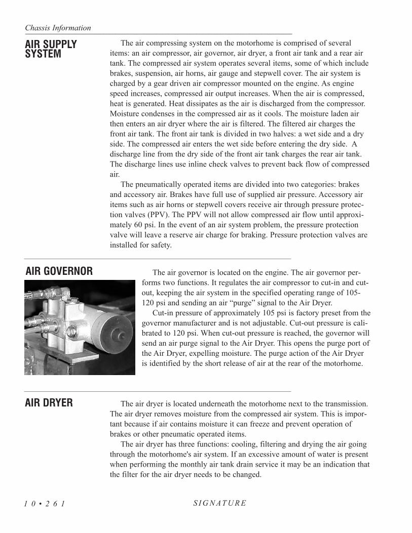
The air compressing system on the motorhome is comprised of severalitems: an air compressor, air governor, air dryer, a front air tank and a rear airtank. The compressed air system operates several items, some of which includebrakes, suspension, air horns, air gauge and stepwell cover. The air system ischarged by a gear driven air compressor mounted on the engine. As enginespeed increases, compressed air output increases. When the air is compressed,heat is generated. Heat dissipates as the air is discharged from the compressor.Moisture condenses in the compressed air as it cools. The moisture laden airthen enters an air dryer where the air is filtered. The filtered air charges thefront air tank. The front air tank is divided in two halves: a wet side and a dryside. The compressed air enters the wet side before entering the dry side. Adischarge line from the dry side of the front air tank charges the rear air tank.The discharge lines use inline check valves to prevent back flow of compressedair.
The pneumatically operated items are divided into two categories: brakesand accessory air. Brakes have full use of supplied air pressure. Accessory airitems such as air horns or stepwell covers receive air through pressure protec-tion valves (PPV). The PPV will not allow compressed air flow until approxi-mately 60 psi. In the event of an air system problem, the pressure protectionvalve will leave a reserve air charge for braking. Pressure protection valves areinstalled for safety.
The air governor is located on the engine. The air governor per-forms two functions. It regulates the air compressor to cut-in and cut-out, keeping the air system in the specified operating range of 105-120 psi and sending an air “purge” signal to the Air Dryer.
Cut-in pressure of approximately 105 psi is factory preset from thegovernor manufacturer and is not adjustable. Cut-out pressure is cali-brated to 120 psi. When cut-out pressure is reached, the governor willsend an air purge signal to the Air Dryer. This opens the purge port ofthe Air Dryer, expelling moisture. The purge action of the Air Dryeris identified by the short release of air at the rear of the motorhome.
The air dryer is located underneath the motorhome next to the transmission.The air dryer removes moisture from the compressed air system. This is impor-tant because if air contains moisture it can freeze and prevent operation ofbrakes or other pneumatic operated items.
The air dryer has three functions: cooling, filtering and drying the air goingthrough the motorhome's air system. If an excessive amount of water is presentwhen performing the monthly air tank drain service it may be an indication thatthe filter for the air dryer needs to be changed.
Chassis Information---------------------------------------------------------------------------------------------------------------------------------------------------------------------------------------------------------------------------------------------------------------------------------------------------------------------
S I G N AT U R E1 0 • 2 6 1
AIR SUPPLYSYSTEM
AIR GOVERNOR
AIR DRYER

During system pressure build-up, compressed air passes into the air dryerwhere the filter system removes contaminants and passes the air into the dry-ing stage. Initially, moisture that condenses out collects in the base of thedryer. Moisture-laden air passes through the desiccant bed in the air dryer car-tridge and is dried. When the compressor unloads, the water is expelled andthe dry air flows back through the dryer, drying the desiccant for the next cycle.
The governor turns the compressor on when supply tank pressure drops belowcut-in pressure. Compressed air passes into the air dryer at the inlet port:
• Moisture-laden air and contaminants pass through the desiccant.• Moisture is retained by the desiccant. Moisture also collects in the
base of the dryer.
When the compressor unloads the purge valve opens. The governor turns thecompressor off when system reaches cutout pressure (approximately 120 psi).
• The dryer purges and expels water collected in the dryer base.• When the regeneration valve opens, the dry system air flows back
through the dryer. A small charge of air from the front tank back-flows through the filter. The backflow dries the desiccant, preparingit for the next cycle.
1. When air is compressed, the compressor takes in water vapor withthe air, compresses the water vapor and puts it into the system as liq-uid water.
2. Liquid water that accumulates in air lines can damage seals andvalves, and wash away lubricants.
3. In cold weather water can freeze, block air lines and damage air sys-tem components.
1. Warm, humid air from the compressor condenses into either liquidwater or water vapor before entering the air dryer.
2. A desiccant-type air dryer protects the motorhome air brake systemby drying moisture-laden air before it passes through the air reser-voirs and into the brake system.
3. Water collects in the base of the dryer when:• Warm air condenses into water before it enters the dryer.• Warm air condenses into water inside of the dryer
before the water reaches the desiccant.4. The desiccant material then removes additional water vapor, further
drying the air. 5. During the regeneration phase, the regeneration valve and pressure-
controlled check valve remove water from the desiccant bed with abackflow of dried, expanded system air.
Chassis Information------------------------------------------------------------------------------------------------------------------------------------------------------------------------------------------------------------------------------------------------------------------------------------------------------------------
S I G N AT U R E 1 0 • 2 6 2
Air Dryer Operation
Air Dryer Cycle
Importance ofthe Air Dryer
Desiccant-TypeAir Dryer

1. Purge Valve: A valve located on the bottom of the airdryer base that remains open during a compressor unloadcycle. The purge valve allows collected moisture, condensationand contamination to be expelled from the air dryer during apurge cycle.
2. Pressure Relief Valve: A valve that protects the air dryerfrom over-pressurization.
3. Regeneration Valve: The valve that controls regenera-tion of the desiccant. The regeneration valve allows air from thesupply and secondary tanks to bypass the outlet check valve.The air expands and back flushes moisture off the desiccantthrough the dryer's purge valve.
Extreme Cold: Make sure the air dryer heater is in goodworking order. The heater in the air dryer is a 100-watt heater
controlled by ignition power and turned off when the ignition is switched off.Thermostat operating range is On below 45° F and Off when the temp is above86° F. The fuse is located in the front electric bay outside, beneath the driverswindow.
WARNING: Remove all pressure from the air system before disconnect-ing any component, including the desiccant cartridge. Pressurizedair can cause serious personal injury.
1. Replacement kit contains one cartridge and one O-ring.2. Loosen and remove the old cartridge. Use strap wrench, if necessary.3. Remove and discard O-ring from dryer base.4. Inspect and clean seal seat. Repair any minor damage.
NOTE: If the seats are damaged so badly that a tight sealcannot be maintained, replace the air dryer.
5. Lubricate O-Ring on stem with a thin layer of grease. 6. Lubricate cartridge seal with a thin layer of grease.7. Thread the replacement cartridge onto the base until the seal
touches the base. Tighten the cartridge ONE additional turn. DONOT OVERTIGHTEN.
Chassis Information---------------------------------------------------------------------------------------------------------------------------------------------------------------------------------------------------------------------------------------------------------------------------------------------------------------------
S I G N AT U R E1 0 • 2 6 3
DesiccantCartridge

The front and rear air tanks should be manually drained once a month, ormore, depending on operating conditions where humidity is high. The frontair tank has a drain valve for both the wet and dry side. The rear air tankonly has one drain valve. Open the drain valves until all air is purged fromtanks, allowing five extra minutes for moisture to be expelled. Remember toclose the tank drain valves. Both air tanks have a pressure relief valve whichis set to release at approximately 130 psi.
Provided for convenience is a remote air supply coupler. Thisis located in the roadside LP Tank compartment. This universalfemale fitting will accept several types of 1/4” ID male air fit-tings, including type C automotive. This auxiliary air fitting maybe used to inflate tires, air mattresses or other pneumatic items.
To use this feature: • Remove the plastic protective dust cap.• Using a firm grip, insert the air fitting into auxiliary air supply.
The locking collar is spring loaded and will lock automaticallywhen the fitting is properly inserted.
Chassis Information------------------------------------------------------------------------------------------------------------------------------------------------------------------------------------------------------------------------------------------------------------------------------------------------------------------
S I G N AT U R E 1 0 • 2 6 4
AIR STORAGETANKS
AIR COUPLER - UNIVERSAL
REPLACEMENT REQUIREMENTSComponents When to replace WhyDesiccant Every two to three years. Preventive maintenance.Cartridge When compressor is replaced. Contaminated cartridge.
Water in supply tank. Saturated or contaminatedcartridge, high duty cycle(wrong application ofair dryer).
1. O - Ring2. Seal Seat3. Seal

Chassis Information---------------------------------------------------------------------------------------------------------------------------------------------------------------------------------------------------------------------------------------------------------------------------------------------------------------------
S I G N AT U R E1 0 • 2 6 5
To remove fitting:• With a firm grip hold the air hose near the fitting to prevent recoil.• Slide the locking collar back to release fitting. The collar will lock
into the open position when fully retracted. • Replace the protective dust cap when finished.
This fitting is not designed to charge the air system on the motorhome. The airsupply for the auxiliary air fitting is charged from the front air tank through apressure protection valve. Due to the small air pressure restriction of the pressureprotection valve, maximum supply pressure is approximately 95 psi with air sys-tem on the motorhome charged to 120 psi.
The air system on the motorhome can be charged from an exter-nal air supply source. Located in the generator compartment is atype C automotive male fitting. Caution should be used when charg-ing the air system from this fitting. The air supplied from an externalsource may contain moisture. Compressed air introduced into the airsystem on the motorhome from this fitting is not filtered by the airdryer. The auxiliary air charge fitting will charge the front and rearair tanks. A check valve is installed to prevent air from escaping.
CAUTION: The external air supply source should be regulated tocharge the air system on the motorhome no higher than 120 psi.Damage to the air system or pneumatically operated items may occur.
The ride height valves inflate or deflate the air bags keeping the motorhome atproper suspension height throughout the load range. There are three ride heightcontrol valves used on the motorhome. Two are used on the rear drive axle to con-trol rear suspension height and left or right tilt of the motorhome. Only one valveis used to control front axle suspension height. The ride height control valves aremounted to the main frame of the motorhome just above the axles. Each valve hasa linkage rod connected the axle. The valves make small air adjustments to the airsprings while traveling. The amount of system air used depends on the type ofroad surface and driving styles.
Should it become necessary to check the suspension ride height, start with hav-ing the air system fully charged and the suspension at a normalized height. Themotorhome must be on a flat level surface. Suspension height distance is meas-ured from the top of the H-Frame to the bottom of the Main Frame Rail. Specifieddistances may vary plus or minus 1/4”. Small offset adjustments to the rear valvesmay be necessary to compensate for slight tilt. Example: Adjusting curbside rearheight control valve up will pivot roadside front corner down.
NOTE: Driveline angle is affected by the suspension ride height. Improperdriveline angle can damage suspension or shorten the life of universal joints.Shock absorbers and air springs are in travel centers at proper ride height.
RIDE HEIGHTVALVES-Adjusting
AIR SYSTEM - CHARGING(EXTERNAL)
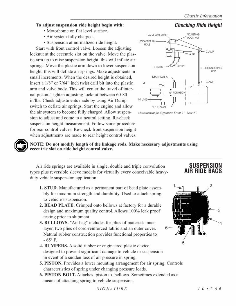
To adjust suspension ride height begin with:• Motorhome on flat level surface.• Air system fully charged.• Suspension at normalized ride height.
Start with front control valve. Loosen the adjustinglocknut at the eccentric slot on the valve. Move the plas-tic arm up to raise suspension height, this will inflate airsprings. Move the plastic arm down to lower suspensionheight, this will deflate air springs. Make adjustments insmall increments. When the desired height is obtained,insert a 1/8” or 7/64” inch twist drill bit into the plasticarm and valve body. This will center the travel of inter-nal piston. Tighten adjusting locknut between 60-80in/lbs. Check adjustments made by using Air Dumpswitch to deflate air springs. Start the engine and allowthe air system to become fully charged. Allow suspen-sion to adjust and come to a neutral setting. Re-checksuspension height measurement. Follow same procedurefor rear control valves. Re-check front suspension heightwhen adjustments are made to rear height control valves.
NOTE: Do not modify length of the linkage rods. Make necessary adjustments usingeccentric slot on ride height control valve.
Air ride springs are available in single, double and triple convolutiontypes plus reversible sleeve models for virtually every conceivable heavy-duty vehicle suspension application.
1. STUD. Manufactured as a permanent part of bead plate assem-bly for maximum strength and durability. Used to attach springto vehicle's suspension.
2. BEAD PLATE. Crimped onto bellows at factory for a durabledesign and maximum quality control. Allows 100% leak prooftesting prior to shipment.
3. BELLOWS. "Air bag" includes for plies of material: innerlayer, two plies of cord-reinforced fabric and an outer cover.Natural rubber construction provides functional properties to- 65º F.
4. BUMPERS. A solid rubber or engineered plastic devicedesigned to prevent significant damage to vehicle or suspensionin event of a sudden loss of air pressure in spring.
5. PISTON. Provides a lower mounting arrangement for air spring. Controlscharacteristics of spring under changing pressure loads.
6. PISTON BOLT. Attaches piston to bellows. Sometimes extended as ameans of attaching spring to vehicle suspension.
Chassis Information------------------------------------------------------------------------------------------------------------------------------------------------------------------------------------------------------------------------------------------------------------------------------------------------------------------
S I G N AT U R E 1 0 • 2 6 6
Checking Ride Height
SUSPENSION AIR RIDE BAGS
Measurement for Signature: Front 9”, Rear 9”.
9”

Listed below are items that can be checked when the motorhome is in forperiodic maintenance.
NOTE: Never attempt to service the air suspension on a motorhome withthe air bags inflated.
• Inspect the O.D. of the air springs. Check for signs of irregularwear or heat cracking.
• Inspect the air lines to make sure contact doesn’t exist betweenthe air line and the O.D. of the air springs. Air lines can rub ahole in an air spring very quickly.
• Check to see that there is sufficient clearance around the completecircumference of the air spring while at its maximum diameter.
• Inspect the O.D. of piston for buildup of foreign materials. (On areversible sleeve style air spring, the piston is the bottom compo-nent of the air spring.)
• The correct ride height should be maintained. All motorhomeswith air springs have a specified ride height established by themanufacturer. This height should be maintained within 1/4”. Thisdimension can be checked with the vehicle loaded or empty.
• The leveling valves (or height control valves) play a large part inensuring that the total air spring system works as required. Clean,inspect and replace if necessary.
• Make sure to check shock absorbers for leaking hydraulic oil andworn or broken end connectors. If a broken shock is found,replace it immediately. The shock absorber will normally limitthe rebound of an air spring and keep it from overextending.
• Check the tightness of all mounting hardware (nuts and bolts). Ifloose, tighten. Do not over-tighten.
CleaningThe approved cleaning method is to use soap and water, methyl alcohol,
ethyl alcohol and isopropyl alcohol. Unapproved cleaning methods include allorganic solvents, open flames, abrasives and direct pressurized steam cleaning.
The motorhome is equipped with air brakes using much the same system asover the road trucks. This type of braking system is very efficient. Proper main-tenance and lubrication is the key to keeping your brake system in proper work-ing order. The brake system on the motorhome is designed to accommodate theweight of the vehicle and towing loads. This system differs from conventionalautomotive hydraulic braking system and should be treated differently.
Chassis Information---------------------------------------------------------------------------------------------------------------------------------------------------------------------------------------------------------------------------------------------------------------------------------------------------------------------
S I G N AT U R E1 0 • 2 6 7
Checklist -Air Bag Inspections
BRAKE SYSTEMS- AIR BRAKES

When operating a vehicle equipped with air brakes, considerations need to begiven to stopping distances and air system pressures. The heavier the vehicle, thegreater the kinetic energy. The motorhome requires longer stopping distances.Each brake application uses air from the air system. Give attention to the airgauge as well as the surroundings. Engine speed is directly proportional to howfast the air system is replenished. Prepare for downhill grades. Grades are general-ly posted in percentages. It may be necessary to select a lower gear. Make use ofthe engine or exhaust brake. When making brake applications, use individual shortapplications down long hills rather than “riding” the brakes. This will extend thelife of the brake linings. Avoid overheating the brakes. Hot brakes have less stop-ping power. When maneuvering the motorhome around in small areas or backinginto spaces, several individual brake applications might be made. Watch the airgauge. Plan ahead when parking to make it easier on yourself. When preparing toback into a space, swing the motorhome so it is aligned with the parking slotbefore backing up.
The air braking system on the motorhome is equipped with several safety fea-tures unlike that of automotive hydraulic braking systems. One safety feature is alow air pressure warning system.Should a low air condition arise while the vehicleis under operation, a warning buzzer will sound and a dash warning light will illu-minate alerting the operator of the situation. This warning occurs at approximately60-65 psi (pounds per square inch).
A simple mechanical explanation of what occurs when a brake application ismade is as follows: The air system supplies air to the foot brake, this is called atreadle valve. Pushing down on the treadle valve supplies an air charge signal to abrake chamber. This sealed chamber consists of a spring and air bladder. The aircharge signal pushes on the bladder which extends a threaded rod connected to theautomatic slack adjuster. The slack adjuster rotates the S-cam expanding the shoesagainst the drum. Air disc brakes follow much the same principal, with the excep-tion of the S-cams.
The park and emergency brake systems are combined and apply to the reardrive axle only. These are called spring brakes. When the park brake is applied, airis released from the rear brake chambers allowing the large spring in each rearbrake chamber to manually push against the automatic slack adjuster. This rotatesthe S-cam applying the brake shoes against the drum. The air system must becharged so the park brake will remain released. Pushing down on the park brakehandle charges the rear brake chambers with air pressure, overriding the emer-gency brake springs and releasing the brakes. In the event of air loss while thevehicle is under operation, the park brake will automatically apply (this occurs atapproximately 30 psi), acting as an automatic emergency brake system.
When preparing to depart, allow the air system to achieve full air pressure.This is indicated by the air gauge needles. Listen for the air dryer to purge, indi-cating full air pressure has been obtained and air dryer is functioning. Look and
Chassis Information------------------------------------------------------------------------------------------------------------------------------------------------------------------------------------------------------------------------------------------------------------------------------------------------------------------
S I G N AT U R E 1 0 • 2 6 8
BRAKE -PARK &
EMERGENCYSYSTEMS

listen for any abnormalities. Abnormal air pressure readings by either needle ofthe air gauge should alert the operator. Have the air system checked to avoid anuntimely failure.
Should a failure occur in the air system, preventing the air pressure frombuilding, it may become necessary to “cage” the spring brakes. This is an emer-gency procedure only. Caging the rear air brake chambers manually overridesthe spring brakes and allows the vehicle to move. This procedure does not affectnormal service braking. The brake disabling procedure is located in Section 2.
NOTE: When the park brake is released, the Park illumination lamp willremain lit until air system pressure is above 65 psi.
The motorhome is equipped with automatic slack adjusters. As brake liningswear, the slack adjusters will automatically ratchet on the return stroke as need-ed. This ratchet action will keep the brake linings at proper adjustment. Brakeadjustment should not be necessary. Indications of a vehicle needing a possiblebrake adjustment may be noticed by the park brake not holding on a hill orgradual loss of braking power. Automatic slack adjusters and the connecting S-camshaft require periodic lubrication.
NOTE: Replacement parts should be of the same original equipment sizeand type. Mixing brake components may result in unequal braking action.Brake adjustments are part of normal maintenance of the motorhome.Brake adjustments are not covered by Monaco Coach Corporation.
WARNING: Brake lining may contain asbestos material and should onlybe serviced by qualified service technicians who are trained in the appro-priate precautionary procedures. If any loss of braking effectiveness orabnormal braking indications are noticed, the brakes and slack adjustersshould be inspected by a qualified brake technician.
The motorhome is equipped with an anti-lock braking system (ABS). TheABS system monitors wheel rotation speeds by using a 100 tooth magnetic tonering mounted to the hub. Revolving with the wheel, the magnetic tone ring ispolarized giving positive and negative pulsations. A stationary sensor is mount-ed adjacent to the tone ring monitoring the magnetic pulses. The pulses aremonitored by the ABS electronic control unit (ECU).
The ECU monitors all available wheel sensors at the rate of 100 times persecond. The ECU controls Pressure Modulator Valves. Pressure ModulatorValves have two electric over air solenoids, a hold solenoid and a release sole-noid. The modulator valves are open under normal braking, allowing a straightthrough air signal from the treadle valve to the brake chamber. Should a wheellose traction under a braking application, the ECU will energize the hold sole-noid of the Pressure Modulator Valve to interrupt the air signal from the treadle
Chassis Information---------------------------------------------------------------------------------------------------------------------------------------------------------------------------------------------------------------------------------------------------------------------------------------------------------------------
S I G N AT U R E1 0 • 2 6 9
BRAKEADJUSTMENT/SLACK ADJUSTER
ABS SYSTEM(Anti-lock Brakes)

valve to the brake chamber, while the release solenoid vents the existing air signalto the atmosphere allowing the skidding tire to regain traction. Skidding tireshave less tractive efficiency. It is possible, under certain conditions, to have thewheel(s) skid with a normal functioning ABS system.
The ABS itself does not apply additional braking power. The purpose of theABS is limiting brake torque to prevent wheel locking that results in the loss oflateral stability and increased stopping distances. Cautious driving practices andmaintaining adequate safe distances when following vehicles is the key to safevehicle operation.
ABS Component Function:• Speed sensors and tone rings on each
wheel monitor wheel rotation.• Each speed sensor communicates
wheel rotation pulses to theElectronic Control Unit.
• ECU receives the speed sensorinputs, interprets the signal pulses,calculates speed and accelerationrates of each wheel.
• Based on the speed sensor input, theECU detects impending wheel lockand operates the ABS ModulatorValves required for proper control.The Modulator Valves can be operat-ed in the air, release or hold modesto regulate air pressure to the brakechambers.
• The braking force is applied at a levelwhich minimizes the stopping dis-tances while maintaining as muchlateral stability as possible.
ABS Warning Light:The ABS will perform a diagnostic indicator lamp check and self diagnostic
test each time the ignition is switched to the on position. The ABS dash indicatorlight will illuminate momentarily (2.2 seconds) verifying the self check test. If theABS indicator light remains on, or illuminates while the motorhome is beingoperated, there is a fault in the antilock brake system only. This fault will notaffect normal service braking. The motorhome will need to go to a service centerto repair the problem.
ABS Blink Code:The ABS dash indicator light can be used to obtain system faults by displaying
a blink code.
Chassis Information------------------------------------------------------------------------------------------------------------------------------------------------------------------------------------------------------------------------------------------------------------------------------------------------------------------
S I G N AT U R E 1 0 • 2 7 0

To retrieve blink code(s) • Turn ignition key to the ON position. • Using Systems Diagnostic Center located left of steering column
below dash board, depress and hold test button for three seconds.Indicator light will illuminate while test button is depressed.
• After releasing test button, indicator lamp will turn off and blinkcode will be displayed: 1-1 will indicate no system faults.
The motorhome air braking system is equipped with several back-up safetysystems and warning alarms in the event of an air system failure. Refinementsto air braking systems have been instituted with safety as top priority. Forexample: should the air compressor fail to charge the air system and the low airgauge readings go undetected, a low air pressure warning buzzer will soundand low air pressure dash warning indicator lamp will illuminate. These warn-ing indicators occur at approximately 65 psi. This will alert the operator of animpending situation. If the motorhome is allowed continued operation, thepneumatic emergency spring brake relay valve installed in the air system sensesthe low air pressure condition. The emergency spring brake relay valve willrelease the air charge from the spring brake air chambers on the rear drive axle.In this case, the park brakes will automatically apply at approximately 30 psi.This safety back-up system acts as an automatic emergency brake system.
Another back up safety is the air system separation of the front and rearbrakes, implemented by using two air tanks. One tank is located in the frontand the other is located in the rear. This separation allows the front air tank tooperate the front brakes, the rear tank operates the rear drive axle brakes andtag axle brakes if equipped with a tag axle. This tank division gives reassurancein the event of one tank having a failure of an accessory air item allowing thecompressed air to escape. Accessory air items are other pneumatically operateditems such as the air horn, step well cover, vacuum generator, etc. The accesso-ry air items operate only when air tank pressures exceed 65 psi. This is donewith pressure protection valves. Should an accessory air item fail, the pressureprotection valve (PPV) will reserve remaining air pressure of 65 psi for brak-ing. This will leave the motorhome with one air tank fully charged for a safetyback up.
Another situation, in which all compressed air has escaped from the rear airtank, a pneumatic back-up safety valve is installed. This is the safety inversionvalve. The inversion valve senses the absence of rear air tank pressure. In thiscase the inversion valve will allow the operator to make a modulated springbrake application, made in conjunction with the emergency spring brake relayvalve. The inversion valve allows the front air tank pressure to recharge therear brake chambers after the modulated spring brake application has beenmade. This back-up system allows use of all the brakes, allowing the operatorto bring the vehicle to a safe stop. In the event of all compressed air chargeescaping from the front air tank, the operator will still have full use of the rearbrakes.
Chassis Information---------------------------------------------------------------------------------------------------------------------------------------------------------------------------------------------------------------------------------------------------------------------------------------------------------------------
S I G N AT U R E1 0 • 2 7 1
BRAKE SYSTEMS-Back-Up

The correct wheel alignment promotes longer tire wearand ease of handling while minimizing the strain on the steer-ing system and the axle components.
Camber:Camber (as shown in diagram) is the verti-
cal tilt of the wheel as viewed from the frontof the vehicle. This is machined into the axlewhen manufactured and is not adjustable.
• “Positive” camber is an outward tilt ofthe wheel at the top.
• “Negative” camber is an inward tilt of thewheel at the top.
Toe Setting:The toe setting represents different dis-
tances between the front and rear of thetires (measured at the vertical centerline ofthe tires).
Toe-in occurs when the tire front dis-tance is less than the tire rear distance.
Toe-out occurs when the tire front dis-tance is greater than the tire rear distance.
Wheels are generally set with initialtoe-in. As the vehicle operates, tires tendtoward a toe-out condition. By startingwith an initial toe-in setting, a desirable“near zero toe-in” can be achieved whenthe vehicle is in motion.
Incorrect toe settings, where toed-in ortoed-out, can have a significant effect ontire wear. The toe setting is adjusted bylengthening or shortening the cross tube.
The toe setting is .03 degree.
Chassis Information------------------------------------------------------------------------------------------------------------------------------------------------------------------------------------------------------------------------------------------------------------------------------------------------------------------
S I G N AT U R E 1 0 • 2 7 2
ALIGNMENT SPECIFICATIONS

Caster Adjustments:Caster is the fore and aft tilt (toward the front or rear of the motor home) of
the steering kingpin as viewed from the side of the motor home. “Positive” caster is the tilt of the top end of the kingpin toward the rear of
the motorhome.“Negative” caster is the tilt of the top end of the kingpin toward the front of
the motorhome.A caster angle more positive than specified may result in excessive steering
effort and/or shimmy. An angle less positive may result in vehicle wander orpoor steering return to center. The caster angle is determined by the installedposition of the steer axle.
Chassis Information---------------------------------------------------------------------------------------------------------------------------------------------------------------------------------------------------------------------------------------------------------------------------------------------------------------------
S I G N AT U R E1 0 • 2 7 3
Min.-0.35º2.00º
-0.05º
Nominal-0.15º3.00º
-0.02º
Min.-0.35º2.00º
-0.05º
Nominal-0.15º3.00º
-0.02º
Max.-0.65º4.00º
-0.08º
CamberCasterToe
CamberCasterToe
Max.-0.65º4.00º
-0.08º
Left Front Right Front

The tag axle is optional equipment on all motorhomes whichare 40 foot. The tag axle design allows for more carry weight,thus making it possible to create a wider variety and range offloor plans.
While the tire should be off the ground there is no specificheight requirement for the tag axle in the up position. If the tagaxle requires being raised higher, adjustments can be made bytaking up one chain link on the tag axle.
The tag axle switch is located on the left hand shifter panel.There are two lights on this switch: One to be lit when theheadlights are turned to the on position. The other to be litwhen the tag axle switch is turned on. The tag axle should onlybe in the raised position when severe maneuvering in yourmotorhome is performed under 5 mph.
If the tag axle switch is in the raised position while you start your coach abeeping alarm will sound. You will need to flip the switch to lower the tagaxle. Once the tag is lowered it will require a few minutes with the enginerunning to build up enough air pressure before it will be ready to travel.
When a tag axle switch is turned on in a motorhome with air leveling thefollowing will take place: The 12 Volt power will be in the 14 gauge yellowwith green stripe wire, which will go all the way to the rear mac valve forthe tag axle located on the roadside rear. Once the rear mac valve has beenactivated the air pressure will go through the orange air line to both tag axlebrake chambers to lift the tag. The air in the air bags will be released to theoutside air. The tag axle will remain in the raised position until the switch isturned to the off position.
The amount of weight carried by the tag axle may be adjusted by chang-ing the amount of downward force applied to the tag axle. Changing theamount of weight carried by the tag axle affects how the weight is distrib-uted between the tag, drive and steering axles. The amount of down forceapplied to the tag axle is controlled by the amount of air pressure in the tagaxle air bags. The amount of air pressure in the tag axle air bags is set by anadjustable pressure regulator located in the engine compartment. The tagaxle regulator pressure is preset at the factory and may require adjustment toobtain the proper weight distribution on all axles. To determine the correctsetting of the pressure regulator the motorhome will need weighed after ithas been loaded for travel.
All tag axles will use the oil bath hubs on the tag axle only. The tag axlehas a chrome hub cap that will need to be removed before the inspection cantake place. You can locate the full and add mark on the outside of the plasticsee-through cover. You will be able to see the oil level. You should inspectthe oil level before every trip or every 5,000 miles.
Chassis Information------------------------------------------------------------------------------------------------------------------------------------------------------------------------------------------------------------------------------------------------------------------------------------------------------------------
S I G N AT U R E 1 0 • 2 7 4
BELOW 0.25" - ADD OILRemove the center hub cap toinspect the tag axle oil level.
TAG AXLE
Oil Bath Hubs (Rear Only)

The frequency of lubricant changes depends upon the individual operatingconditions, speeds and loads. Change whenever the seals are replaced orwhen the brakes are relined or at 30,000 miles (48,000km). If yearly mileageis less than 30,000 miles, change it twice a year (spring and fall).
For low mileage operations the grease may not need changing until every50,000 miles (80,500km) or two years. However, check the grease twice ayear (spring and fall) for contamination. Change if required.
Your tag axle has come to you with Shell Hypoid gear oil, GL-5, S.A.E.80w/90. Specifications, minimum outside temperature -15ºF (-26.1ºC). Thereis no upper limit on these outside temperatures of oils and greases. The axlesump temperature must never exceed 250ºF (+121ºC).
The recommended oil change interval is based on the operating condi-tions, speeds and loads. Limited service applications may allow the recom-mended interval to be increased. Severe applications may require the recom-mended interval to be reduced. For more information contact a Meritor serv-ice representative.
Lubricating the Camshaft Bushings:Apply the specified grease at the grease fitting on the spider. Apply
grease until new grease purges from all the seals. Greasing intervals will beonce a year, or every 30,000 miles. Use a multi-purpose grease NLGI Grade1 or 2. The grease classification should be lithium 12-hydroxy stearate orlithium complex.
NOTE: Under no circumstance should you ever drive the motorhomeover 5 mph when the tag axle is raised. Monaco Coach Corporation willnot be held liable for any damage that may occur while driving over 5mph with a raised tag axle.
Chassis Information---------------------------------------------------------------------------------------------------------------------------------------------------------------------------------------------------------------------------------------------------------------------------------------------------------------------
S I G N AT U R E1 0 • 2 7 5
catesunt
Oil Lube Intervals
Shaded area indicates thecorrect amount of oil.

The shock absorber by definition is a hydraulic device used to dampensuspension/body movement. The road surface irregularities or roughness iscompensated for by the shock absorber. The roadmaster chassis incorporatesthe “Bilstein” shock in the design of the exclusive air glide suspension sys-tem. This shock absorber is a telescopic, monotubed unit filled with nitrogengas and hydraulic oil. The result of the mixture is uninterrupted damping forthe smallest of wheel deflections.
By design, a self lubricating seal is used which will allow approximately10% of the total oil capacity to pass onto the piston rod. The gradual processof oil loss does not affect the performance of the shock absorber during theservice life. This process will be evident after a long period of service by anoil film on the body of the shock absorber. The appearance of a coating orfilm on the body or rod is completely normal, it is an indication the shock isfunctioning normally.
The road holding, handling, balance and braking characteristics all canbe contributed to the shock absorber. The operating conditions for which theshock absorber must endure will determine the life span. However, since theonly moving part is the piston rod there are no spring or hinge pins to wearout, get weak or deteriorate.
Chassis Information------------------------------------------------------------------------------------------------------------------------------------------------------------------------------------------------------------------------------------------------------------------------------------------------------------------
S I G N AT U R E 1 0 • 2 7 6
Normal shock absorberappearance after long service period.
SHOCKABSORBERS

The three point leveling system features a multiple warning system withflashing light and a bong alarm to alert you of the jack position. The systemalso features a remote control panel located next to the driver seat. The tor-sion stress is significantly reduced during proper operating procedures.Damage resulting from improper procedures can range from windshield dam-age to entry doors jamming.
The model 35 J-II leveling system pump is located curbside front witheasy access from the generator door. The valve assembly manifold is mount-ed on the the pump motor, providing easy access to the manual retractvalves. The system is designed to be self bleeding in the event any compo-nent of the hydraulics has been removed or repaired. Fully extend and retracteach jack twice. The remote rocker switches will operate with a minimum of7.5 vdc. Optimum requirements for operating the system are voltages above9.6 vdc.
The Auto leveling system consists of two primary control components: atransmitter module located in the first storage compartment overhead and theremote control panel located next to the driver’s seat. The remote controlpanel is compromised of the various retract/extend switches for the jack legs,a switch for automatic leveling and all retract and the power ON/OFF switch.
NOTE: The leveling system jacks are not designed for use in changingtires. This can cause problems with the suspension system, frame align-ment and damage to the windshields.
Chassis Information---------------------------------------------------------------------------------------------------------------------------------------------------------------------------------------------------------------------------------------------------------------------------------------------------------------------
S I G N AT U R E1 0 • 2 7 7
LEVELING SYSTEM-Hydraulic LevelingSystem (RVA)

When manually operating the leveling system always lower the front jackfirst. The front jack acts as a pivot point for chassis and reduces torsion stresson the body of the motorhome.
NOTE: In the event the front of the motorhome is high and does notrequire elevating it will be necessary to raise front of motorhome a mini-mum of 1/2 inch to allow jacks to act as a pivot point.
The leveling system was designed to reduce site selection problems. Ifpossible, park the motorhome with the front facing downhill. If the groundis soft place a wooden 2 x 8 board under the foot of each jack pad to preventsinking.
The front jack will be the pivot point for the chassis and is always low-ered first. This reduces the torsion stress on the body of the motorhome. TheBong alarm will activate when any jack is extended more than 2” to 6” fromfully retracted position and will indicate low fluid level for the pump motor.The Bong alarm may momentarily activate when driving over rough roads,or negotiating curves and corners. Usually this indicates low fluid level.
NOTE: Air will automatically dump from air bags when leveling cyclebegins. This will lower the motorhome and require less extension by thejacks. To expedite the air dumping the motorhome is equipped with amanual air bag release switch located on the dash panel.
• Place the gear selector in neutral.• Apply the parking brake.• Turn the ignition switch to the ON position.• Engage switch labeled POWER on jack control console.• Each yellow light and switch combination corresponds to each jack as
positioned on the chassis and is labeled as such.• To extend a particular jack, push rocker switch to extend the side and
hold until the desired extension is reached.• To retract a particular jack, simply push rocker switch to the retract posi-
tion and hold until the desired retraction is reached.• When the yellow light goes off, that particular jack is in the level posi-
tion.• Turn off the switch labeled POWER on the jack control panel.• Turn off the ignition switch.
Chassis Information------------------------------------------------------------------------------------------------------------------------------------------------------------------------------------------------------------------------------------------------------------------------------------------------------------------
S I G N AT U R E 1 0 • 2 7 8
Manual Leveling

The ALL JACKS RETRACT mode or MANUAL mode can be engaged atany time during automatic leveling operation.
Prior to automatic leveling it is essential that there is no movement in themotorhome. To extend the jacks automatically proceed as follows:
• Place gear selector in NEUTRAL.• Apply the parking brake.• Turn ignition switch to the ON position.• Switch the main jack control power switch ON.• Press the AUTOMATIC LEVELING/ALL JACKS switch.
If the yellow lights illuminate, press down the rocker switch labeled AUTO-MATIC LEVELING and release. The top green light will start blinking. Aftera ½ second delay, pump motor will come on and all jacks will extend down-ward. The system will attempt complete leveling in one operation. Themotorhome is level when all yellow lights, as well as green lights, go out.
If leveling is unsuccessful on the first phase the system will attempt to levelfour subsequent times at seven second intervals.
If both green lights start flashing alternately the motorhome has reachedmaximum extension on one or more jacks. One or more yellow lights willblink, indicating that additional height is required under one of the jack pads.This can be attained by moving motorhome to another location or getting addi-tional height by placing a 2x8 block under one of the jack pads.
If you block under a jack pad, ONLY ONE JACK SHOULD BE BLOCKEDAT A TIME. If blocking a rear jack pad while motorhome is on a slope, oppo-site set of rear wheels must be chocked to prevent rolling.
WARNING: Once jacks are extended down a red JACKS DOWN warninglight will blink and an alarm will sound. An alarm will sound again ifjacks are down and ignition switch is turned ON.
Once motorhome is level turn off POWER switch on control console andturn off ignition switch. BEFORE DRIVING OFF ALWAYS PERFORM AVISUAL INSPECTION TO INSURE THAT JACKS ARE UP.
Automatic Retract:Prior to retracting levelers it is advisable to start engine and build air pressure.
• Gear selector should be in NEUTRAL.• Parking brake applied.• Turn ignition switch to ON position.• Engage power switch to ON position on jack control console.• Press down rocker switch labeled ALL JACKS RETRACT and release.
CAUTION: Do not move motorhome while jacks are still in contact withground or extended, damage to jacks can occur. Do not raise any wheels offthe ground, which could result in damage to the motorhome.
Chassis Information---------------------------------------------------------------------------------------------------------------------------------------------------------------------------------------------------------------------------------------------------------------------------------------------------------------------
S I G N AT U R E1 0 • 2 7 9
AutomaticLeveling System

Bottom green light will begin blinking and all jacks will retract. Thisoperation is on a four minute timer which green light will stop blinking andgo out.
Hydraulic pressure, in all jacks, is automatically released when ALLJACKS switch is engaged. Jacks are retracted by the weight of motorhomeand retract springs on each jack.
Manual Retract Valves:In the event of mechanical or electrical failure that
would prevent the leveling jacks from being automati-cally retracted, the motorhome is equipped with manu-al emergency retract valves. These valves are locatedinside the front generator access.
This manual system will release fluid under pres-sure in each jack and allow fluid to return to the reser-voir. The jacks will then retract.
To operate the manual system turn all three valvescounterclockwise until they stop.
Once the jacks are fully retracted, rotate all thevalves fully clockwise. In the event one of the jacks isnot holding pressure, check the position of the retractvalve.
NOTE: Do not move the motorhome until the jacks are fully retracted.
CAUTION: The motorhome will raise or lower as the bypass valves areopened. Do not crawl under the motorhome to access the valves. Makesure there is ample room to open the valves safely.
Maintenance:Occasionally, while the jacks are fully extended, wipe dirt from the jack
rod. This will help lengthen the life of the jacks. This can vary from theamount and type of usage of the jacks. Dexron III will serve as a solvent aswell as a lubricant. Occasional oil or grease on the extended jack ram is nor-mal and aids in the lubrication of the ram. It helps to learn the sound of thenormal pumping and gurgling sounds of the pump when it is low on fluid.
Calibration:The transmitter module may require recalibration to ensure an accurate
level is obtained. The recalibration procedure requires two persons for con-venience and accuracy. This should only be performed by qualified servicetechnicians.
Chassis Information------------------------------------------------------------------------------------------------------------------------------------------------------------------------------------------------------------------------------------------------------------------------------------------------------------------
S I G N AT U R E 1 0 • 2 8 0

Adding Fluid:1. An indication of a system needing fluid is a chime sounding when
turning corners. Use Dexron III automatic transmission fluid. 2. Extend any jack 6 inches from the full retracted position. All other
jacks should be fully retracted.3. Unscrew the reservoir cap from the top of the pump.4. Turn the ignition switch to the ON position. Turn the power ON rock-
er switch. Open the window so the bong alarm is audible from out-side the motorhome. Slowly fill the reservoir with fluid until the bongalarm stops sounding.
5. Replace the reservoir cap.6. Turn the ignition switch and the remote panel OFF.
A touch panel, computer controlled, four point or six point air levelingsystem is optional on all models. Models which are equipped with the airleveling system must remember the ignition has to be ON for the suspensionto operate. This is critical to note in the event the motorhome requires emer-gency towing.
Automatic Air Leveling:• Air leveling will operate faster if engine is running.• Set parking brake.• Transmission must be in neutral. (Important: No movement in
motorhome while leveling.)• Press AIR button once to enter air mode. AIR indicator light and four
AIR BAG warning lights will glow steady.• Press AIR button a second time. AIR indicator light will start flashing
and air leveling will begin.• When all four yellow LEVEL SENSING lights are out leveling is com-
plete. AIR indicator light will stop flashing and turn steady red.Processor is now in a SLEEP MODE for 30 minutes. Engine maynow be turned off. Every 30 minutes processor will checkmotorhome’s level condition, make any corrections and return toSLEEP MODE. This will continue until system is turned off bypushing OFF button or transmission is taken out of neutral positionand parking brake released.
Excess Slope:If system was unable to level motorhome, one or two yellow LEVEL
SENDING indicator lights will remain on and EXCESS SLOPE light willcome on. System will remain on but will not go into SLEEP MODE.
Chassis Information---------------------------------------------------------------------------------------------------------------------------------------------------------------------------------------------------------------------------------------------------------------------------------------------------------------------
S I G N AT U R E1 0 • 2 8 1
LEVELING SYSTEM-Air (Optional)

Manual Air Leveling Operation:
• Air leveling will operate faster if engine is running.• Set parking brake.• Transmission must be in neutral.• Press the AIR button once. AIR indicator light will glow steady.• Individual RAISE and LOWER buttons (UP or DOWN ARROWS)
will add or dump air from suspension air bags to raise or lower coachfor leveling.
• These are momentary buttons. Function will stop when button isreleased. Yellow LEVEL lights indicate a side, end or corner ofmotorhome is low. Lower opposite side or end of motorhome toachieve leveling. If a level position cannot be achieved by dumpingair, raise motorhome according to lighted yellow LEVEL lights.
• IMPORTANT: Always give preference to any side light before level-ing motorhome front to rear.
• Turn ignition switch OFF. Turn air leveling system OFF.
Start engine and allow air pressure to build to recommended pressure fortravel. Push system OFF button and allow motorhome to return to travelposition. All red indicator lights must be OFF and travel indicator lightmust be lighted before traveling. Ensure that the motorhome is at the properride height before moving. DO NOT solely rely upon the warning lights.
CAUTION: Do not rely solely upon warning lights. It is the operator’sresponsibility to check that the motorhome is at the proper ride heightbefore moving the motorhome.
Chassis Information------------------------------------------------------------------------------------------------------------------------------------------------------------------------------------------------------------------------------------------------------------------------------------------------------------------
S I G N AT U R E 1 0 • 2 8 2
Red
- Green
Air Leveling - Traveling Preparation

The diesel engine operates differently from the conventional gasolineengine. Gasoline engines control engine speed using a butterfly throttle platecontrolling air/fuel mixture inlet flow. As the throttle plate opens, vacuumcreated by the piston velocity draws the metered fuel/air charge into the com-bustion chamber, then ignited from a controlled electric ignition source.Closing the throttle plate limits the fuel/air supply, slowing engine speed,increasing intake manifold vacuum.
The diesel engine in the motorhome controls engine speed by varying fuelsupply only. No throttle plates are used. An exhaust driven turbine system(turbocharger) compresses the fresh air supply into the engine. The fuel isinjected under pressure into the combustion chamber. Ignition of fuel/aircharge occurs from heat generated by rapid high compression. The turboboost gauge registers amount of intake manifold compression measured inlbs./in². Therefore, no intake manifold vacuum exists.
Diesel engine RPM (revolutions per minute) operating speeds are general-ly much lower than that of the gasoline engine. Peak torque and horsepoweroutput values occur at much lower engine speeds. Idle speeds between thetwo engine types are similar, however maximum engine speeds are quite dif-ferent. The gasoline engine generally is not regulated to a maximum enginespeed. The maximum engine speed on a diesel engine is controlled by anengine speed governor set by the engine manufacturer.
WARNING: Do not operate a diesel engine where there are or can becombustible vapors. Vapors can be drawn through air intake system andcause engine acceleration and over-speeding, resulting in fire, explosionand extensive property damage.Numerous safety devices are available,such as air intake shutoff devices, to minimize risk of over-speedingwhere an engine (due to its application) might operate in a combustibleenvironment, such as fuel spills or gas leaks. Equipment owner andoperator is responsible for safe operation of engine. Consult your engineauthorized repair location for future information.
Chassis Information---------------------------------------------------------------------------------------------------------------------------------------------------------------------------------------------------------------------------------------------------------------------------------------------------------------------
S I G N AT U R E1 0 • 2 8 3
ENGINE- GENERAL INFORMATION

With the throttle in the idle position, turn the key to the start position.When the engine has started release the key. Allow the engine to idle with noload for 3-5 to five minutes. The engine coolant temperature should be up tonormal operating range (140º F / 60º C to 212º F / 100º C) before operatingthe engine under full throttle.
NOTE: The ISM engine does not have a “wait to start” feature.
The engine block heater may need to be plugged in 2 to 3 hours prior tostarting. The engine block heater is rated at 1500 watts, 110 volts AC andrequires the motorhome be plugged into shore power or have the generatorrunning. It is not necessary to leave the block heater plugged in for long peri-ods of time. The block heater requires about 13 amps to operate.
The maintenance guidelines found in the Cummins O & M manual isrecommended for the engine. When followed it will help with a longer life,better performance and more cost efficient operations. A good maintenanceschedule begins with a daily awareness of the engine and its various sys-tems.
A high grade 15W-40 multiviscosity heavy duty lubricating oil meetingCummins Engineering Specification CES 20071 or CES 20076, AmericanPetroleum Institute (API) specification CH-4 which can be used as an alter-native to CES 20071 is recommended. Lubricating oils meeting API CG-4specifications may be used at a reduced drain interval. Monaco CoachCorporation uses Pennzoil 15W-40 heavy duty engine lubricating oil thatmeets Cummins specifications. A critical factor in maintaining engine per-formance and durability is the use of high grade multigrade lubricating oiland strict adherence to the maintenance service intervals.
A straight weight or monograde lubricating oil is not recommended.Shortened drain intervals may be required as determined by a close monitor-ing of the lubricating oil condition by means of a oil sampling program. Theuse of oil analysis to extend drain interval is not recommended. There arenumerous variables which is the basis of the recommendation.
Synthetic oils API category III specifications are recommended forextreme cold temperatures only.
Low viscosity oils used for winter operations will aid in starting.Synthetic oils or oil with adequate low temperature properties used for Arcticoperations, where the engine can not be kept warm when shut down, will aidin starting.
The use of synthetic oils should not be used to extend drain intervals.Extended oil change intervals can decrease engine life and possibly affect theengine warranty.
Oil additives should not be used unless the oil supplier or oil manufactur-
Chassis Information------------------------------------------------------------------------------------------------------------------------------------------------------------------------------------------------------------------------------------------------------------------------------------------------------------------
S I G N AT U R E 1 0 • 2 8 4
STARTING PROCEDURE
-COLD WEATHER
OIL RECOMMENDATIONS
(ENGINE)
ENGINE STARTINGPROCEDURE(ISM Normal)

er has been consulted and provided positive evidence or data establishing sat-isfactory performance in the engine.
Oil Function of Engine Oil:If a lubricating oil is to work in an engine it must be capable to perform
various functions. Lubrication of the moving parts is the primary function.The lubricating oil should be able to form a film between metal surfaces pre-venting metal to metal contact and reducing friction. When you have a metalto metal contact, friction heat is generated. Welding of the part can occur andmetal transfer will result in scuffing or seizing. The film of oil contacting thesurfaces will provide cushioning and shock dampening as well.
Cleaning is another function. The oil should perform as a cleaner in theengine by flushing contaminates from critical components. These contami-nates should be removed in the filtration system or during the course of anoil change. Oil will provide a protective barrier to prevent corrosion of non-like metals.
Internal components of the engine require cooling. The primary coolantsystem cannot provide this cooling. Oil will transfer heat by contacting thevarious components then transferring to the primary cooling system at the oilcooler. The uneven surfaces are filled to react as a combustion seal within thecylinder liner and other internal components.
Synthetic Engine Oil:Extreme environments where ambient temperatures can be as low as
-45º C (50º F) a petroleum based oil will not perform satisfactorily in dieselengines. Synthetic oils were developed for these type applications. Thesesynthetic oils are a blend from either ester and/or hydrocarbon based oils.These base oils are produced by chemically reacting lower molecular weightmaterials to manufacture lubricants of desired properties. All synthetic basedoils must meet the API category III classifications and SAE viscosity grades.Synthetic oils and petroleum based oils should never be mixed.
Viscosity:Viscosity is simply a measure of resistance of molecule layers moving
relative to an adjacent layer. All fluid viscosity are affected by temperature. Amultigrade lubricating oil tends to be less sensitive to temperature changesdue to formulation. Lubricating oils are generally selected for use with vis-cosities appropriate for the expected operating temperature. The correctselection of a lubricating oil of correct viscosity is critical for optimum per-formance. Some effects of incorrect viscosity when the oil is too thick rangefrom difficulty in starting to increasing fuel consumption and reducing poweroutput. When the oil is too thin, oil consumption is increased as well as wearfrom the metal to metal contact. This will also increase engine noise.
Low temperature viscosity specifications are identified by a “W” (winter).
Chassis Information---------------------------------------------------------------------------------------------------------------------------------------------------------------------------------------------------------------------------------------------------------------------------------------------------------------------
S I G N AT U R E1 0 • 2 8 5

High temperature viscosity that meets the 100º C (212º F) requirements haveno suffix. When a lubricating oil meets both high and low temperaturerequirements they are classified as multi-viscosity or multigrade.
Routine Maintenance Recommendations:
1. Check oil level daily.
2. Replace oil filter at every oil drain interval.
3. Cummins Engine Company, Inc. recommends the use of high quality,API (American Petroleum Institute) licensed CH-4 or CES20071,15W-40, multiviscosity oil or premium oil.
4. The recommended oil drain interval is defined by the API oil perform-ance classification and the engine duty cycle. Refer to the CumminsOperation and Maintenance Manual for complete details.
It is possible to operate diesel engines in extremely cold environments.The engine should be properly prepared and maintained. The correct lubri-cants, fuels and coolant MUST be used for the cold weather range for whichthe motorhome is being operated. Cold weather operation can be defined intwo categories: Winterize and Arctic.
NOTE: Refer to the Operations and Maintenance Manual for moredetailed information.
WINTERIZE (32º to -25º F) (0º to -32º C): Use a 50 antifreeze / 50water coolant mixture, use multi-viscosity oil meeting Cummins specifica-tions and fuel to have maximum cloud pour points 10º F (6º C) lower thanthe ambient temperature in which the motor home operates.
ARCTIC (-25º to -65º F) (-32º to -52º C): Use a 60 percent antifreeze /40 water coolant mixture, use oil meeting Cummins specifications and fuel tohave maximum cloud pour points 10º F (6º C) lower than the ambient tem-perature in which the motorhome operates.
Chassis Information------------------------------------------------------------------------------------------------------------------------------------------------------------------------------------------------------------------------------------------------------------------------------------------------------------------
S I G N AT U R E 1 0 • 2 8 6
Oil Recommendations-Cold Weather

General guidelines for shutting the engine down are fairly simplistic.Allow the engine to idle 3 to 5 minutes after a full load operation. Thisallows adequate cool down of pistons, cylinders, bearings and turbochargercomponents. Under normal driving conditions, exiting the highway is gen-erally lighter engine operation and the need for the 3 to 5 minutes is notnecessary.
When the motorhome has been sitting for extended periods, 30 days ormore, verify all the fluid levels are correct. Follow the normal starting pro-cedures. If the oil pressure gauge does not register within 15 seconds, shutoff the engine immediately to avoid damage. Consult the CumminsOperations and Maintenance Manual for guidelines on troubleshooting lowoil pressure, or contact a qualified service technician. Allow the engine toidle for 3 to 5 minutes before operating under a load.
A fully formulated antifreeze or coolant containing a precharge ofSupplemental Coolant Additives (SCA) is recommended. The use of eitherwill significantly simplify coolant system maintenance. The differencebetween a fully formatted antifreeze and a fully formatted coolant is thepercentage of water. Both contain balance amounts of antifreeze, SCA,buffering compounds and a percentage of good clean quality water. Theantifreeze of coolant must meet ethylene glycol or propylene glycol recom-mendations. A good clean quality water in a 50/50 ratio (40 to 60 percentworking range) mixed with fully formatted antifreeze will provide protec-tion from -34º F to 228º F. The 50/50 mix ratio must be premixed prior tobeing put in the system. Placing antifreeze and water in the cooling systemis not recommended. Consult the O&M manual for more details.
NOTE: An over concentration of antifreeze, or the use of high silicateantifreeze, can cause damage to the coolant system and engine.Antifreeze is essential in every climate.
The coolant fluid freeze point should be checked with every oil changeinterval at 15,000 miles, 500 hours or 6 months, whichever comes first.Also change the coolant filter at the same interval unless SCA concentra-tion is over three units. The coolant should be drained and flushed at 6000hours or 2 years of service, whichever comes first.
Chassis Information---------------------------------------------------------------------------------------------------------------------------------------------------------------------------------------------------------------------------------------------------------------------------------------------------------------------
S I G N AT U R E1 0 • 2 8 7
ENGINESHUTDOWN-Extended
ENGINESHUTDOWN
COOLANT

Engine Coolant Reservoir:A “see-through” plastic reservoir, similar to the familiar windshield wash-
er jar, is connected to the radiator by a hose. As the motorhome is drivencoolant is heated and expands. A portion of fluid displaced by this expansionflows from the radiator into the reservoir tank. When the engine is stopped,and coolant cools and contracts, displaced coolant is drawn back in the radia-tor by a vacuum. Thus, the radiator is kept filled with coolant to the desiredlevel at all times resulting in increased cooling efficiency. The coolant levelshould be at or above the appropriate mark on the reservoir tank when thesystem is cold.
• Check the coolant level daily or when refueling.• Drain and flush the coolant system every 60,000 miles or two years, and
refill with a heavy-duty coolant (50/50 mix of water and anti-freeze).• If the coolant is below the MIN mark, the low coolant alarm will sound
and the low coolant light will appear on the dash. You will need to stopand check for coolant loss before driving.
• The coolant level is to remain between the MAX and MIN level in thereservoir.
Routine Maintenance Recommendations:
1. Check the SCA concentration level every 15,000 miles/6 months.2. Change the coolant filter every 15,000 miles/6 months.3. Drain and flush the system every 240,000 miles/2 years, and refill with
a heavy-duty coolant (50/50 mix of water and antifreeze).4. Always use antifreeze. In addition to freeze protection, antifreeze is
essential for overheat and corrosion protection.5. The supplemental coolant additive (SCA) is required.6. Freeze point should be measured every 15,000 mile/6 months.
Chassis Information------------------------------------------------------------------------------------------------------------------------------------------------------------------------------------------------------------------------------------------------------------------------------------------------------------------
S I G N AT U R E 1 0 • 2 8 8
The coolant capacity, when changing theantifreeze, is approximately 11½ gallons.

Fully formulated products contain SCA and are requiredto protect the cooling system from fouling, solder bloomingand general corrosion. The cooling filter is required to pro-tect the coolant system from abrasive materials, debris andprecipitated coolant additives.
Supplement coolant additives, or equivalent, are used toprevent liner pitting, corrosion and scale deposits in thecooling system. Use the correct Fleetguard coolant filter tomaintain the recommended SCA concentration in the sys-tem. Maintain the correct concentration by changing the
service filter at each oil drain interval.
NOTE: The correct filter is determined by the total cooling systemcapacity and oil drain interval. Refer to the Coolant CapacitySpecifications in this section.
CAUTION: Insufficient concentration of the coolant additives willresult in liner pitting and engine failure. The SCA concentration mustnot fall below 1.2 units or exceed 3 units per gallon of cooling systemcapacity.
Use the correct Fleetguard coolant filter to maintain the recommendedSCA concentration in the system. Maintain the correct concentration bychanging the service coolant filter at each oil drain interval. The oil pres-sure gauge, temperature gauge, warning lamps and other safety lampsshould be checked daily to ensure proper operations.
NOTE: The correct filter is determined by the total cooling systemcapacity. If you have any questions refer to the Cummins manual.The engine does not require a “break-in” procedure.
Low sulphur #2 diesel fuel or #1 and #2 commercial winter blend dieselfuels are the most common commercially available and recommended foruse. The Cummins Engine Company Inc. recommends the use ASTM #2Dfuel. The use of #2 diesel fuel will result in optimum engine performance.
WARNING: Do not mix gasohol with diesel fuel. This mixture cancause an explosion.
NOTE: Due to the precise tolerances of diesel injection systems, it isextremely important that fuel be kept clean and free of dirt or water.Dirt or water in the system can cause severe damage to both the fuelpump and the fuel injector. Fuel additives for lubricity are not recom-mended. There are numerous diesel fuel additives to help remove mois-ture from fuel, prevent microbe growth and to prevent freeze-up dur-ing cold weather. Any fuel additives product should show supportingdata for performance and benefits. Engine failures caused by incorrectfuel are not covered under warranty.
Chassis Information---------------------------------------------------------------------------------------------------------------------------------------------------------------------------------------------------------------------------------------------------------------------------------------------------------------------
S I G N AT U R E1 0 • 2 8 9
FUELREQUIREMENTS
Coolant - Additive (SCA)

The "Jake" brake is an engine brake which uses the energy of the enginescompression to slow down the motorhome. The engine brake efficiencyincreases with engine speed; therefore, gear selection is important. The "World"Allison transmission will automatically select the best downshift gear upon actua-tion of the foot switch for the Jake Brake.
The engine brake uses a hydraulic circuit that opens the exhaust valves near theend of the compression stroke. The amount of braking power depends on tur-bocharger boost pressure, engine speed, compression ratio, injector timing andwhen the brakes open the exhaust valves.
Engine brake controls with the fuel system consist of the following:
1. A two-position selector switch. 2. An ON/OFF switch, which is the foot switch. 3. A throttle sensor.
Other switches for cruise control which affect engine brake operations are:
1. Cruise control ON/OFF and SET/RESUME switches (if the Engine Brakes inCruise Control feature is turned “OFF”).
2. Service brake air pressure switch (if pedal activated engine braking isenabled).
The two-position selector switch, located on the driver’s left console, allows youto select the retarding power of one or two brakes.
“LOW” activates the engine brake on three cylinders.“HI” activates the engine brake on six cylinders. The engine ECM then electronically enables or disables the engine brakes.
Engine brakes cannot be enabled:
1. When the cruise control is active and if the engine brakes in cruise control fea-ture is turned OFF.
2. When engine speed goes below 850 rpm.3. When an electronic fault code is active. The throttle sensor is part of the accel-
erator pedal assembly located in the cab and will deactivate the engine brakeswhen depressed. The service brake pressure switch is attached to the servicebrake air supply line. Applying the service brakes while in cruise control willdisengage the cruise and enable the engine brakes. The Jake Brake can beused continuously down a hill, or a long freeway off ramp. The engine brak-ing system will allow the engine temperature to drop while going downhill.
NOTE: Idle the engine 3 to 5 minutes at approximately 1000 rpm to warm theengine before activating the engine brakes. Do not operate the engine brakesuntil the engine oil temperature is above 30 degrees C (86 degrees F).
WARNING: The engine brakes (Jake Brake) are designed to assist themotorhome.
Chassis Information------------------------------------------------------------------------------------------------------------------------------------------------------------------------------------------------------------------------------------------------------------------------------------------------------------------
S I G N AT U R E 1 0 • 2 9 0
BRAKE - ENGINE
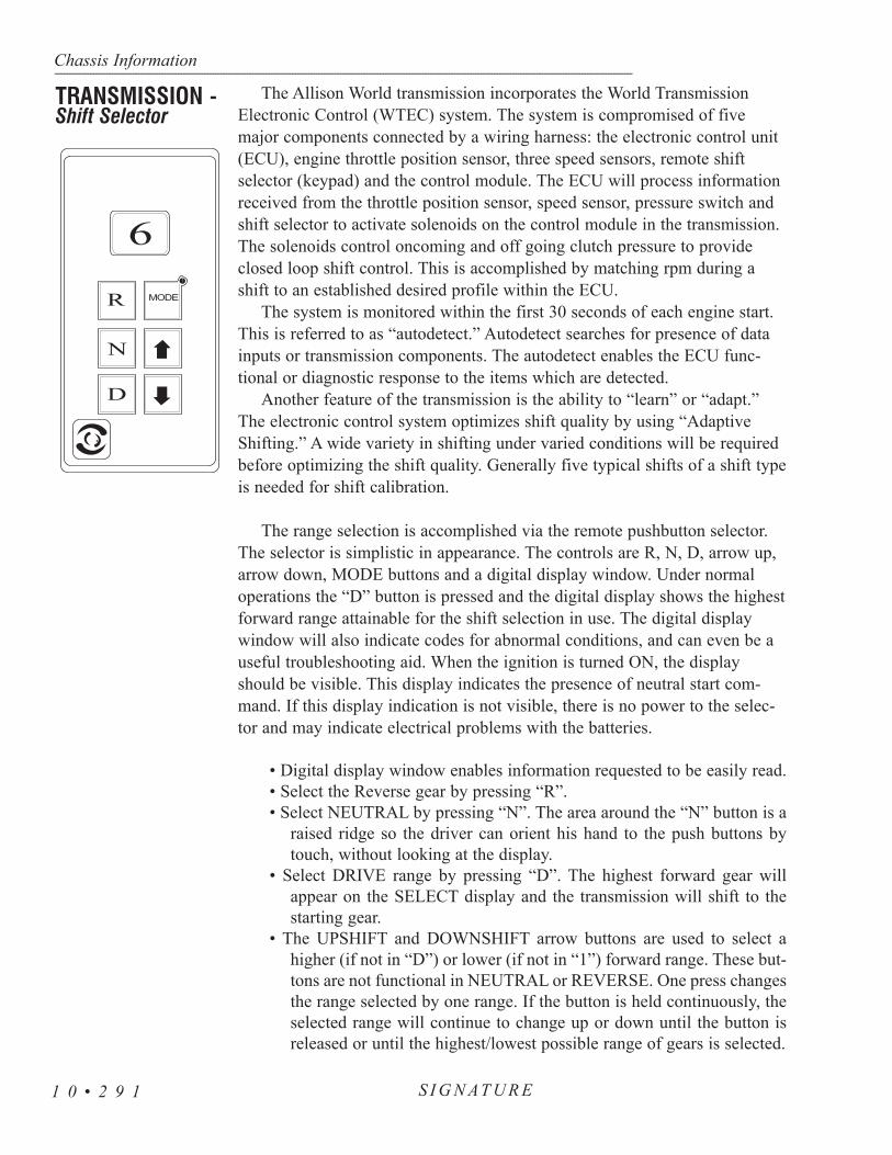
The Allison World transmission incorporates the World TransmissionElectronic Control (WTEC) system. The system is compromised of fivemajor components connected by a wiring harness: the electronic control unit(ECU), engine throttle position sensor, three speed sensors, remote shiftselector (keypad) and the control module. The ECU will process informationreceived from the throttle position sensor, speed sensor, pressure switch andshift selector to activate solenoids on the control module in the transmission.The solenoids control oncoming and off going clutch pressure to provideclosed loop shift control. This is accomplished by matching rpm during ashift to an established desired profile within the ECU.
The system is monitored within the first 30 seconds of each engine start.This is referred to as “autodetect.” Autodetect searches for presence of datainputs or transmission components. The autodetect enables the ECU func-tional or diagnostic response to the items which are detected.
Another feature of the transmission is the ability to “learn” or “adapt.”The electronic control system optimizes shift quality by using “AdaptiveShifting.” A wide variety in shifting under varied conditions will be requiredbefore optimizing the shift quality. Generally five typical shifts of a shift typeis needed for shift calibration.
The range selection is accomplished via the remote pushbutton selector.The selector is simplistic in appearance. The controls are R, N, D, arrow up,arrow down, MODE buttons and a digital display window. Under normaloperations the “D” button is pressed and the digital display shows the highestforward range attainable for the shift selection in use. The digital displaywindow will also indicate codes for abnormal conditions, and can even be auseful troubleshooting aid. When the ignition is turned ON, the displayshould be visible. This display indicates the presence of neutral start com-mand. If this display indication is not visible, there is no power to the selec-tor and may indicate electrical problems with the batteries.
• Digital display window enables information requested to be easily read.• Select the Reverse gear by pressing “R”.• Select NEUTRAL by pressing “N”. The area around the “N” button is a
raised ridge so the driver can orient his hand to the push buttons bytouch, without looking at the display.
• Select DRIVE range by pressing “D”. The highest forward gear willappear on the SELECT display and the transmission will shift to thestarting gear.
• The UPSHIFT and DOWNSHIFT arrow buttons are used to select ahigher (if not in “D”) or lower (if not in “1”) forward range. These but-tons are not functional in NEUTRAL or REVERSE. One press changesthe range selected by one range. If the button is held continuously, theselected range will continue to change up or down until the button isreleased or until the highest/lowest possible range of gears is selected.
Chassis Information---------------------------------------------------------------------------------------------------------------------------------------------------------------------------------------------------------------------------------------------------------------------------------------------------------------------
S I G N AT U R E1 0 • 2 9 1
TRANSMISSION -Shift Selector
R
N
D
6
MODE

• The MODE button will enable secondary shift point to be selected. Thisis commonly referred to as “Economy.” It is further used by the serv-ice technician to access diagnostic codes when troubleshooting. Thediagnostic circuitry must be enabled to display.
The electronic control system is programmed to inform the operator of aproblem with the transmission system and automatically take action to pro-tect the operator, motorhome and transmission. When the Electronic ControlUnit (ECU) detects a DO NOT SHIFT (DNS) condition the ECU restrictsshifting, turns the CHECK TRANS light on the instrument panel and regis-ters a diagnostic code.
NOTE: For some problems, diagnostic codes may be registered withoutthe ECU activating the CHECK TRANS light. An Allison Transmissionauthorized service outlet should be consulted whenever there is a trans-mission related concern. They have the equipment to check for diagnos-tic codes and to correct problems which arise.
Each time the engine is started the CHECK TRANS will light, then turnoff after a few seconds. This momentary lighting is to show that the statuslight circuits are working properly. If the CHECK TRANS light does notilluminate during start up, or if the light remains on after start up, the systemshould be checked immediately.
Continued illumination of the CHECK TRANS light during vehicle oper-ation (other than start up) indicates that the ECU has signaled a diagnosticcode. Illumination of the CHECK TRANS light is accompanied by a flash-ing display from the shift selector. The shift selector display will show actualrange attained and the transmission will not respond to shift selector requests.
Indications from the shift selector are provided to inform the operator thatthe transmission is not performing as designed and is operating with reducedcapabilities. Before turning the ignition off, the transmission may be operatedfor a short time in the selected range in order to “limp home” for serviceassistance. Service should be performed immediately in order to minimizepotential for damage to the transmission.
When the CHECK TRANS light comes on and the ignition switch isturned off, the transmission will remain in N (Neutral) until the conditioncausing the CHECK TRANS light is corrected. Generally, while the CHECKTRANS light is on, upshifts and downshifts will be restricted and directionchanges will not occur. Lever and push-button shift selectors do not respondto any operator shift request while the CHECK TRANS light is illuminated.The lockup clutch is disengaged when transmission shifting is restricted orduring any critical transmission malfunction.
Chassis Information------------------------------------------------------------------------------------------------------------------------------------------------------------------------------------------------------------------------------------------------------------------------------------------------------------------
S I G N AT U R E 1 0 • 2 9 2
Transmission - Check Light

Diagnostic Codes:The diagnostic codes are numerical representations of malfunctions in the
transmission operations. Each code is a two digit main code and a two digitsub code. The codes, when detected, are logged in the ECU memory. Thesecodes will fall in two classes: active and inactive. Active codes are codes cur-rently effecting the ECU process. Inactive codes are retained but may noteffect the ECU process. The diagnostic mode must be entered. A maximumof five codes, D1 to D5, may be listed at one time. The highest priority codewill be listed in D1. The MODE button will enable selection of sequentialcodes.
• Enable Diagnostic Code Selection Display• Stop the motorhome at a safe location.• Apply the parking brake.• Simultaneously press the up and down arrows twice to enter the stored
codes. The first time the arrows are pressed will indicate the oil levelsensor information.
• The codes will display one digit at a time.• The mode button is pressed to scroll through the codes.• Any code obtained should be noted and reported to an Allison Service
Center for evaluation and possible repair.• Inactive codes can be cleared by holding the MODE button for approxi-
mately 3 seconds. Some codes are self clearing while others willrequire service or ignition cycles to clear.
The Allison MT Series requires minimum maintenance. Careful attentionto the fluid level and the connections for the electronic and hydraulic circuitsis very important.
For easier inspection, the transmission should be kept clean. Make period-ic checks for loose bolts and leaking fluid lines. Check the condition of theelectrical harnesses regularly. Check the engine cooling system occasionallyfor evidence of transmission fluid which would indicate a faulty oil cooler.Report any abnormal condition to an Allison dealer.
Prevent Major Problems:Help the WTEC III control system oversee the operation of the transmis-
sion. Minor problems can be kept from becoming major problems if younotify an Allison Transmission distributor or dealer when one of these condi-tions occur:
1. The shifting feels odd. 2. The transmission leaks fluid.3. There are unusual transmission-related sounds (changes in sound
caused by normal engine thermostatic fan cycling, while climbing a
Chassis Information---------------------------------------------------------------------------------------------------------------------------------------------------------------------------------------------------------------------------------------------------------------------------------------------------------------------
S I G N AT U R E1 0 • 2 9 3
Transmission-Periodic Inspections

long grade with a heavy load, have been mistaken for transmission-related sounds).
4. The CHECK TRANS light comes on frequently.
The Importance of Proper Fluid Levels:The transmission fluid cools, lubricates and transmits hydraulic power. It
is important that the proper fluid level be maintained at all times. If the fluidlevel is too low the converter and clutches do not receive an adequate supplyof fluid. If the fluid level is too high the fluid can aerate. Aerated fluid cancause the transmission to shift erratically or overheat.
The MT Series oil level sensor (OLS) allows the operator to obtain anindication of sensor fluid level from the keypad shift selector. Frequentlycheck for the presence of oil level diagnostics in the transmission. If the OLShas not been detected troubleshooting of the OLS circuit is required. Thiswill have to be performed by an Allison Service Center. After the OLS circuitis repaired, ensure that reset of the “autodetect” or manual selection of theOLS function, using the Pro-Link, has been accomplished.
Fluid Level Check with the Keypad:• Park the motorhome on a level surface, place the transmission in “N” and
set parking brake.• The transmission should be at normal operating temperature.• The motorhome should be stationary for approximately two minutes to
ensure fluid is stabilized.• Simultaneously press the arrow up and arrow down buttons one time.• The delayed fluid level check will display in the digital display window.
The display will be one character at a time. The “o,L” represents oillevel check mode. This will be followed with fluid level indicationreadings. The “o,K” indicates a correct fluid level. Reading betweenthe OLS and the dipstick may not agree because the OLS compensatesfor fluid temperatures. Abnormal indications of the OLS will be “Lo”representing a low fluid level, “HI” for a high fluid level or “oL” forinvalid information and system problems. All indications will be fol-lowed by numeric values. The “Lo” and “HI” followed by the numericvalue represents the quarts of fluid required for the system. The invalidcode numbers represent specific symptoms.
Chassis Information------------------------------------------------------------------------------------------------------------------------------------------------------------------------------------------------------------------------------------------------------------------------------------------------------------------
S I G N AT U R E 1 0 • 2 9 4

Common Oil Level Fault Codes:
• 0,5 settling time too short.• 5,0 speed RPM too low.• 5,9 speed RPM too high.• 7,0 sump temperature too low.• 7,9 sump temperature too high.• 9,5 OLS FAILURE.
Exit the fluid level display by pressing any range button on the key-pad.
NOTE: To correctly check the transmission fluid level using the dip-stick, the transmission fluid must be at operating temperature. Theoil level sensor method of checking the fluid level compensates fortransmission fluid temperature between 60ºC - 104ºC (140ºF -220ºF).Any temperature below 60ºC (140ºF) or above 104ºC (220ºF) willresult in an Invalid for Display condition.
Any fluid meeting DEXRON-III specifications are acceptable for usein the transmission. Transmission performance, reliability and durabilityare important influences in the type of fluids used. Change the fluidinternal filters after the first 8000km (5000 miles). The dipstick/oil fill islocated between the engine and transmission underneath the engineaccess door in the bedroom. Change the transmission fluid and internalfilters every 40,000km (25,000 miles) or 18 months, whichever occursfirst.
Fluid and Internal Filters Change Interval Recommendations The fluid and internal filters may require changing earlier depending
on the severity of operating conditions. The fluid must also be changedwhenever there is evidence of dirt or high temperature conditions as indi-cated by discoloration, strong odor or fluid analysis. Local conditions,severity of operation or duty cycle will dictate more or less frequentservice intervals.
Chassis Information---------------------------------------------------------------------------------------------------------------------------------------------------------------------------------------------------------------------------------------------------------------------------------------------------------------------
S I G N AT U R E1 0 • 2 9 5
TRANSMISSIONLUBRICATINGFLUID

Manual Check Procedures:The concept of a cold check is to determine adequate fluid level for safe
operating until hot check can be performed.
• Park the motorhome on a level surface using the service brakes.• The engine is operated at a low idle. Put the transmission in N (Neutral).• Apply the parking brake and chock the wheels to prevent the motorhome
from moving.• Allow the engine to run at idle (500-800 rpm) for one minute.• Apply the service brakes and shift to D (Drive), then to N (Neutral) and
next to R (Reverse) to fill the system. Finally shift to N (Neutral) andrelease the service brakes. Allow the engine to continue to run at idle(500-800 rpm).
• Remove the dipstick and wipe clean. Reinsert the dipstick fully into thetube and remove to check fluid level. Repeat this to verify the readingif needed.
• Safe operating level is anywhere within the COLD CHECK band on thedipstick. The fluid level is sufficient enough to operate until a HOTCHECK can be run.
• If the level is not within this band, add or drain the fluid as necessary tobring the level to the middle of the COLD CHECK band.
• Perform the HOT CHECK the first opportunity after reaching normaloperating temperatures (160º-200º F / 71º-93º C).
CAUTION: Low or high fluid level can cause overheating and irregularshift patterns. These conditions can damage the transmission if not cor-rected.
Chassis Information------------------------------------------------------------------------------------------------------------------------------------------------------------------------------------------------------------------------------------------------------------------------------------------------------------------
S I G N AT U R E 1 0 • 2 9 6
Transmission Oil Level Dipstick.
Cold Check

• The fluid level rises as the temperature increases, the fluid must be hotto ensure an accurate check.
• Be sure the fluid has reached normal operating temperature (160º-200ºF/71º-93º C). If a transmission temperature gauge is not present, checkthe fluid level when the engine water temperature gauge has stabilizedand the transmission has been operated under the load for at least onehour.
• Park the motorhome on a level surface and shift to N (Neutral). Applythe parking brake and allow the engine to idle (500-800 rpm).
• After wiping the dipstick clean, check the fluid level. Safe operatinglevel is anywhere within the HOT RUN band on the dipstick.
• The width of the HOT RUN band is approximately 1 quart of fluid atnormal temperature range.
• If the level is not within this band, add or drain the fluid as necessary tobring the level within the HOT RUN band.
• Be sure that the fluid level checks are consistent. Check the level morethan once. If the readings are not consistent check to be sure that thetransmission breather is clean and not clogged. If the readings are stillnot consistent, contact the nearest Allison distributor or dealer.
The diesel fuel tank is made of 160 thousands aluminum. The capacity ofthe tank is 200 gallons. The engine pickup tube is cut at a 45 degree angle toallow good flow to the engine.
NOTE: If the coach has been stored for any length of time you shouldcheck the vent for blockage. It is not uncommon for insects to plug thevent tube. If the tank appears to be pressurized the vent tube may beblocked. To inspect the vent tube check on the roadside of the fuel tank,near the bottom.
Routine Maintenance Recommendations:
1. Change the fuel filter at every oil change interval.2. Change the fuel-water separator filter every 12-18 months or every
25,000 miles.
Chassis Information---------------------------------------------------------------------------------------------------------------------------------------------------------------------------------------------------------------------------------------------------------------------------------------------------------------------
S I G N AT U R E1 0 • 2 9 7
FUEL TANK
Hot Check

The Centroid fuel sender has no moving parts. It works by measuringcapacitance, an electrical property, between its inner and outer tubes in thetank. The more fuel between the tubes, the higher the reading. Electronics inthe hockey-puck head of the sender convert the capacitance to current todrive the fuel gauge.
Connections:The Centroid sender has four connections:
• Positive and Negative: Battery voltage to run the electronics in the sender head.
• Send: Connects to the Send terminal of the gauge on the dash.
• Alarm: Makes a connection internally to the Negative terminalwhen the low alarm fuel level is reached (when gauge is readingabout 1/8 tank). This turns on the alarm light on the dash. It is notadjustable.
Adjustments:The Centroid sender has two adjustments:Empty: Adjusts for length of sender. It has been set at the factory and covered with a sealant. It should not be changed.
Full Adjustment: The full adjustment can be used to correct for slight differences between fuel meters. During installation, it has been calibratedfor your meter and should not need readjustment.
The correct adjustment technique, with a full tank of fuel, is to startwith the full adjustment screw completely clockwise. This should cause thereading to be above full. Adjust slowly counterclockwise until the full markis reached.The intent is to always adjust downscale rather than upscale.
Troubleshooting:A. Electronic output. The sender has a transistorized output. This prevents
an ohmmeter from getting a correct reading of its output resistance. B. Fuel Only: The sender will not work correctly in conducting fluids such
as water (it will read above full all the time in water). One possibility,when you have a constant above-full reading, is that you have water atthe bottom of the fuel tank.
C. Contact Centroid: Probably 90% of the returns Centroid tests work okayon the bench. If you have incorrect readings contact Centroid (telephone: 800-423-3574, or (preferable) fax: 904-423-3709) with your symptoms.You will be provided with a short “fill in the blanks” troubleshooting testappropriate to your sender. It is easier to find the problem that way thanafter the sender has been removed from the system, since the problem isnot necessarily with the sender.
Chassis Information------------------------------------------------------------------------------------------------------------------------------------------------------------------------------------------------------------------------------------------------------------------------------------------------------------------
S I G N AT U R E 1 0 • 2 9 8
FUEL SENDINGUNIT
Fuel Sending Unit.

Operation/Restart After Running Out Of Fuel
• Turn the ignition switch to the ON position.• The green power light on the control panel should illuminate.• Remove the cap from the Schrader air valve and press and release the
“AIR PURGE” switch on control panel. The yellow “AIR PURGE”lamp will illuminate. Depress and hold the Schrader air valve open torelease the excess air from the system. The electronics will maintainthe pump operation for 50-60 seconds. Recycle the pump and when thefuel is observed from the Schrader valve release (so the fuel no longerleaks from it).
• The internal pump will continue to run, pressurizing the fuel systemwhile forcing fuel through the fuel lines.
• It may require recycling the “AIR PURGE” about 6 times before pullingenough fuel from the tank to filter.
NOTE: The engine may run rough for a few minutes while the remain-ing air, if any, is forced through the fuel system.
• If the water in fuel light is illuminated on the dash, follow the sameprocedure using the H20 button on the control panel. It may be neces-sary to change the fuel filter.
NOTE: Always carry an extra Racor element as one tank full of exces-sively contaminated diesel fuel can plug a filter.
Servicing the Reusable Pre-Filter:• Remove the thumb bolt, washer and top block. Remove the pre-filter
and o-rings.• Clean the pre-filter in a solvent bath or with compressed air as neces-
sary. Remember to wear safety goggles.
Chassis Information---------------------------------------------------------------------------------------------------------------------------------------------------------------------------------------------------------------------------------------------------------------------------------------------------------------------
S I G N AT U R E1 0 • 2 9 9
Fuel/Water Separator(ISM Engine)

• Inspect the O-rings for cuts ordamage. Replace if needed,otherwise lube with motor oilor clean the fuel and replace.
• Install the pre-filter back into thebottom block (the pre-filterarrow points down), andreplace the top block makingsure the O-rings are properlyseated.
• Replace the thumb bolt andtighten by hand. Using pliers,turn the bolt 3/4 of one turnfirmly to seat the O-ring seals.
NOTE: Over tightening may result in damage to the unit.
• Activate the “AIR PURGE” switch, start and operate the engine at highidle for about 3 minutes.
The motorhome uses an engine driven hydraulic pump to operate both thepower steering system and the engine hydraulic cooling fan system. Thehydraulic pump is a dual stage pump which uses one half of the pump tosupply pressurized hydraulic fluid to the power steering. The other half of thepump supplies the engine cooling fan motors. The hydraulic system uses thesame fluid for both systems, sharing one common reservoir. The hydraulicfluid used is an automatic transmission fluid (Dexron3) which has a wideambient temperature operating range.
CAUTION: If ambient temperatures approach 0º F, Penzoil ArticBlue hydraulic fluid, or equivalent hydraulic fluid, should be used.Using incorrect hydraulic system fluid weights in cold or arctictemperatures will raise the hydraulic system operating pressureand may damage the hydraulic cooler.
The hydraulic pump creates pressure by meshing sets of gears togetherinside a close tolerance housing. A filtered supply of hydraulic fluid from thehydraulic reservoir enters the intake side of the pump. The meshing gearassembly “squeezes” the oil through the pump to the output side deliveringthe pressurized fluid to the power steering gear and the switching valve ofthe engine cooling system. Each half of the pump is equipped with an inter-nal by-pass pressure relief spring. If the hydraulic pressure should exceed the
Chassis Information------------------------------------------------------------------------------------------------------------------------------------------------------------------------------------------------------------------------------------------------------------------------------------------------------------------
S I G N AT U R E 1 0 • 3 0 0
HYDRAULIC SYSTEMS (ISM)
Hydraulic Pump
Water Pump.

specified pressure limit, the internal by-pass relief valve will be forced opento keep the hydraulic fluid at operating pressure. The hydraulic pressure gen-erally is not rated in psi but is rated in the term bar. One bar is equivalent toapproximately 14.5 psi. Hydraulic system pressures with a system at no loadmay be as low as eight bar on the output side of the pump. This is due to thehydraulic fluid flow of the pump. When a load is placed on the hydraulicpump, such as turning the steering wheel, hydraulic fluid flow slows fromhydraulic fluid restriction and creates pressure.
This may be understood as a faucet with a garden hose attached.Crimping the hose with the faucet on will create pressure from the restric-tion. This principal applies to the hydraulic system. The hydraulic pump isthe supply, the load would be the power steering gear or the hydraulic fanmotors. Hydraulic system pressure at full load can exceed 130 bar or 2000psi. Hydraulic system pressure falls dramatically after the load. The returnline pressure may be as low as six to eight bar. The fluid enters the hydrauliccooler where the heat is dissipated.
The hydraulic cooler is an important part in the hydraulic system. Thishelps keep the hydraulic fluid from overheating. When a load is placed onthe hydraulic system, heat is created in the fluid. The hydraulic pump buildspressure creating heat in the fluid. The restriction from the loads applied alsocreates heat. This heat must be dissipated to keep the hydraulic fluid fromoverheating and breaking down. After cooling, the fluid is filtered beforereturning to the reservoir.
Care must be used when starting an engine in very cold or arctic climates.As with any oil, lower temperatures thicken the oil. Hydraulic system pres-sures increase due to the thickness of the fluid. Even though the hydraulicpump is equipped with pressure relief valves, the thick oil on the return linecan exceed the operating pressure of the hydraulic cooler.
The hydraulic fan drive system cools the radiator, charge air cooler,hydraulic fluid cooler, transmission cooler and the dash air conditioning con-denser. The components of the hydraulic fan system are: hydraulic reservoir,filter, pump, two hydraulic fan motors, hydraulic switching valve and ther-movalve. Cooling fan speed is proportional to engine speed and radiator tem-perature. When radiator temperature rises above 185º Fahrenheit, the waxthermovalve slowly closes off the bypassing hydraulic fluid from the switch-ing valve. As radiator temperature rises a spool valve begins to move in theswitching valve. This directs the pressurized hydraulic fluid to the fanmotors. The higher the radiator temperature, the further the spool valve ismoved in the switching valve, providing a higher volume of pressurizedhydraulic fluid to the fan motors. Fan motor speed is increased to meet thedemand for cooling. The action of the thermovalve is designed to move the
Chassis Information---------------------------------------------------------------------------------------------------------------------------------------------------------------------------------------------------------------------------------------------------------------------------------------------------------------------
S I G N AT U R E1 0 • 3 0 1
Hydraulic Cooler
Hydraulic Fan System
spool in the switching valve to ramp up fan motor speed. This design saveshorsepower and increases fuel mileage by precise control of hydraulic fanmotor speed . The fan motors will increase in speed when the motorhome isascending long hills or operating in high ambient temperatures. It is normalfor the fans to “roar” when they are operating. Fan motor speed and enginerpm are approximately the same with the switching valve at full engagement.
The wax filled thermovalve is mounted at the top of the radiator sensingcoolant temperature. The thermovalve controls the action of the switchingvalve. When the radiator is cool, the hydraulic fluid is allowed to flowthrough the inlet and outlet ports of the thermovalve and return to thehydraulic reservoir. As the coolant temperature inside the radiator rises toapproximately 185º Fahrenheit, the wax inside the thermovalve begins tomelt and expand. This begins to restrict hydraulic fluid flow through the ther-movalve. The restricted hydraulic fluid pressure then begins to move theinternal spool valve of the switching valve. This process will continue untilcoolant temperature inside the radiator reaches approximately 199ºFahrenheit. At this temperature hydraulic fluid flow through the thermovalveis stopped, moving the spool valve to full open position.
NOTE: The ISM series engine has a piloted orifice at the inlet portof the switching valve. This allows the fan motors to spin at a lowrpm, even when the radiator is cool. This is to keep the dash airconditioning compressor at proper operating temperatures. It isnormal for the engine fans to spin when the engine is idling even atcool radiator temperatures.
The switching valve is mounted to the fan motor. This valve controlsdirection of high pressure hydraulic fluid flow. High pressure hydraulic fluidcomes from the hydraulic pump to the switching valve and is returned backto the reservoir. Either the thermovalve or the electric override valve directsthe fluid to the spool in the switching valve. When the radiator is cool, pres-surized hydraulic fluid will bypass the fan motors and return to the fluidreservoir. As radiator temperature rises, the thermovalve signal is slowed orstopped to the switching valve. High pressure fluid is then directed to the fanmotors, cooling the radiator.
Motorhomes equipped with an ISM engine have an electric overhydraulic override control valve. The override valve is located at the lowerrear corner of the radiator package. This valve is a normally closed valvewhich is plumbed parallel with the thermovalve. It performs the samehydraulic signal function as the thermovalve, but is electrically controlled bythe ISM engine. The ISM engine monitors intake manifold temperature. The
Chassis Information------------------------------------------------------------------------------------------------------------------------------------------------------------------------------------------------------------------------------------------------------------------------------------------------------------------
S I G N AT U R E 1 0 • 3 0 2
Thermovalve
Switching Valve
Electric Override(ISM engine)

electronics of the ISM engine control an 87a relay located in the rear run boxmarked Hyd. Fans. When intake manifold operating temperatures are normal,the electronic engine energizes the coil of the relay. This energizes the coil ofthe override valve and the hydraulic fluid signal flows through the overridevalve to the thermovalve. If the ISM engine detects an over temperature con-dition of the intake manifold, the coil of the 87a relay is deactivated. Powerto the override valve is removed, hydraulic fluid flow signal is stopped andinternal spool of the switching valve moves to full open position. The highpressure fluid is directed to fan motors cooling the radiator.
The fan motors are driven by hydraulic fluid pressure from the switchingvalve. The fan motors work on the same mechanical principal as a hydraulicpump, only the mechanical principal when applied to the fan motors isreversed. Instead of creating hydraulic pressure by meshing gears together ina close tolerance housing, the fan motors receive hydraulic pressure. Thehydraulic fluid drives the fan motor’s internal gear assembly, spinning thefan motors and the attached fan blades. The switching valve is mounted toone fan motor. The fluid is directed to the input of that motor first. The out-put of the first motor is hooked to the input of the second motor. Thehydraulic fluid is then cooled and filtered before returning to the reservoir.
The hydraulic reservoir is located in the engine com-partment. It is made from aluminum so the tank will not beaffected by any moisture which may condense. The oillevel in the reservoir should be checked when the hydraulicfluid is at operating temperature. This should be doneevery 6000 miles or three months. The oil dipstick/oil fillis located on top of the reservoir. The oil level should bekept between the full and add marks on the dipstick. Whenperforming fluid level checks, inspect fittings and hoses forsigns of leakage. Look underneath the motorhome for anysigns of fluid leakage. Avoid untimely and costly failuresby having leaks repaired. Change the hydraulic oil filterevery 15,500 miles or once a year. Total system capacity isapproximately 46 quarts.
Chassis Information---------------------------------------------------------------------------------------------------------------------------------------------------------------------------------------------------------------------------------------------------------------------------------------------------------------------
S I G N AT U R E1 0 • 3 0 3
Fan Motor
Hydraulic Reservoir
Hydraulic Fluid Reservoir.

The Interceptor series hydraulic filter system located inthe engine compartment has special features to protect theprecision tolerance hydraulic components. The filter headassembly has a built in sight gauge which indicates fluidflow through the filter. A specially designed media filterabsorbs harmful contaminants such as moisture and dirt.When the engine is running, use the sight gauge to checkthe filtering process. The green zone indicates thehydraulic fluid is being properly filtered and flowing unre-stricted through the filter and head assembly back to thereservoir. As the filter traps harmful debris and contami-nants, the indicator will move into the red zone. When theindicator is in the red zone, it is indicating filter is cloggedand fluid is bypassing the element returning to the reser-voir. The filter head is equipped with a built in bypass valve. This prevents aclogged filter from developing a leak due to excess hydraulic fluid pressureinside a clogged filter.
The filter is rated at ten micron*. Change the filter before the built insight gauge is operating in the red zone. This will ensure the hydraulic fluidis properly filtered.
Filter number: Parker IN HC 5720 (ten micron)*One micron is one millionth of one meter.
Maintain the grease pack behind the output shaftdirt and water seal as a general maintenance proce-dure at least twice a year. The grease fitting is pro-vided in the housing trunnion. Use NLGI grade 2 or3 multipurpose chassis lube and use only a handoperated grease gun on the fitting. Add grease untilit begins to extrude past the sector shaft dirt andwater seal.
Power steering is provided by using hydraulicpressure to assist rotating the output shaft of thesteering gear. Located at the end of the input shaftof the steering gear is poppet valve and worm drive.The poppet valve directs the hydraulic fluid pres-sure to a type of spool. The worm drive threads in the center of the spool.When in the center position pressurized hydraulic fluid bypasses the spool.When a turn is made the poppet valve shifts to one direction or the other,directing the hydraulic pressure to one side of the spool depending on turningdirection. The hydraulic fluid is then cooled before returning to the reservoir.Inspect for signs of leakage when performing fluid level checks. Changingthe hydraulic filter at regular intervals will help ensure trouble free operation.
Chassis Information------------------------------------------------------------------------------------------------------------------------------------------------------------------------------------------------------------------------------------------------------------------------------------------------------------------
S I G N AT U R E 1 0 • 3 0 4
Hydraulic Filter (ISM Engine)
STEERING GEAR
Hydraulic filter for the power steering and hydraulic coolingfans.

The disc brake components need to be lubricated to ensure proper brakeoperation. The calipers and slack adjusters need to be lubricated two orfour times during the life of the brake pad lining or every six months. Thelubricating procedure involves mechanically adjusting the brakes and willrequire an assistant. The motorhome must be parked on a flat level surfaceduring the lubrication process. The drive axle spring brakes will need to becharged by releasing the emergency brake or an alternate method of releas-ing the spring brakes is by caging the spring brake chambers. If the springbrake chambers are going to be caged, the caging procedure is explained inthe section under Towing Procedures. To ensure safety prior to releasingthe spring brakes, special precautionary procedures are required to preventthe motorhome from rolling. Use at least four wheel chocks located at twoseparate wheel positions. Place each wheel chock snug against the forwardside and backside of each tire with the wheel chocks facing opposite direc-tions. The wheel chocks will remain in place until the brakes are adjustedand the proper brake pad to rotor clearance has been verified.
Lubricate the brake components at each wheel position. The lubricantrequired is a special high temperature grease. Refer to the grease chart forthe lubricant specifications.
WARNING: Use wheel chocks prior to the lubrication procedure.Use at least four wheel chocks located at two separate wheel posi-tions. Place each wheel chock snug against the forward side andthe backside of each tire with the wheel chocks facing oppositedirections. The wheel chocks will remain in place until the brakesare adjusted and the proper brake pad to rotor clearance hasbeen verified. Failure to use wheel chocks can result in propertydamage, severe injury or death.
NOTE: Lubricate the brake actuating components inside thecaliper at least two to four times during the life of the lining orevery six months. Use only high temperature lubricant whichmeets or exceeds the required specifications.
Lubricate the caliper camshaft firstthen lubricate the slack adjuster. Toensure the grease thoroughly lubricatesthe camshaft, the slack adjuster will bemanually adjusted full distance in eachdirection. Manually adjusting the slackadjuster will move the camshaft throughthe entire range of motion ensuringproper lubrication.
Chassis Information---------------------------------------------------------------------------------------------------------------------------------------------------------------------------------------------------------------------------------------------------------------------------------------------------------------------
S I G N AT U R E1 0 • 3 0 5
LUBRICATING THE CALIPER

1. Begin the lubrication procedure by first installing the wheelchocks. Release the spring brakes.
2. Rotate the adjusting nut on the slack adjuster counterclockwise,this will move the inboard brake pad against the rotor.
3. The poppet on the caliper pressure relief valve will need to beheld closed to prevent the grease from escaping during the lubrica-tion process. With a finger holding the poppet valve closed, applythe high temperature grease through the grease fitting closest tothe rotor first. Stop greasing when the lubricant begins to be forcedout of the camshaft dust cover which is located between thecaliper and slack adjuster.
4. Remove the pressure relief valve from the caliper.
CAUTION: Failure to remove the pressure relief valve will leaveexcess grease in the caliper. This will cause the brakes to dragdue to the excess grease pressing on the caliper camshaft.Reduced brake pad life will result.
5. Using a flat blade screwdriver hold the adjusting nut locking pawlopen and rotate the adjusting nut on the slack adjuster clockwiseuntil the caliper piston is fully retracted. As the caliper piston isretracted the excess camshaft lubricant will be forced out throughthe pressure relief hole.
6. With a finger covering the pressure relief hole, grease the fittingon the caliper closest to the slack adjuster. Stop when the excessgrease begins to be forced out of the camshaft dust cover. Removethe excess grease from the camshaft dust cover and caliper.
7. Install the pressure relief valve.8. Lubricate the slack adjuster grease fitting until the new lubricant
is forced out of the locking pawl.
NOTE: Use only specifically designed products such as a brakecleaner to remove any lubricant from the brake surfaces.
Chassis Information------------------------------------------------------------------------------------------------------------------------------------------------------------------------------------------------------------------------------------------------------------------------------------------------------------------
S I G N AT U R E 1 0 • 3 0 6

Proper clearance between the rotors and brake pads is necessary for cor-rect brake operation. Brake pad clearance which is too small will result inoverheated brake linings. Brake pad clearance which is too large will resultin insufficient braking force and improper parking brake operation. A staticbrake adjustment procedure will approximate the proper brake pad to rotorclearance. The spring brakes remain released throughout the static brakeadjustment process. After the static brake adjustment procedure verify thebrake pad clearance by measuring how far the brake chamber rod extendswhen the brakes are applied.
NOTE: If the emergency brake has automatically set due to low airpressure, start and run the engine until full air system pressure isobtained. Release the emergency brakes.
Static Brake Adjustment:
1. Set the static distance between the brake pad and rotor byrotating the adjusting nut on the slack adjuster counterclock-wise until the nut stops. The brake pad should be firmlyagainst the rotor.
2. Using a flat blade screwdriver hold the adjusting nut lockingpawl open. Rotate the adjusting nut clockwise ¾ turn.
3. If applicable, uncage the spring brakes and return the cagingtool to the storage position.
Verifying the Brake Adjustment:
The proper clearance of the brake pads should now be verified. The brakechamber rod will extend when a brake application is made. The distance therod extends must fall within specification. Measure the distance on eachbrake chamber rod.
WARNING: Keep all fingers and loose clothing clear from movingbrake components.
Chassis Information---------------------------------------------------------------------------------------------------------------------------------------------------------------------------------------------------------------------------------------------------------------------------------------------------------------------
S I G N AT U R E1 0 • 3 0 7
Adjusting the Brakes

1. Using a tape measure, record the distance between the flatsurface of one brake chamber and the slack adjuster clevis pin.
2. With wheel chocks in place, start and run the engine until theair system is fully pressurized. If necessary, charge the springbrakes by releasing the emergency brake. Stop the engine.
3. Have the assistant make a brake application. Using a tapemeasure, record the distance between the flat surface of thatsame brake chamber and the slack adjuster clevis pin.
4. Repeat this procedure for all the brake chambers. Start theengine if the air system pressure drops to 80 psi.
5. Subtract the distance measured in line 2 from the distancemeasured in line 3. Record the measurement. Each brakechamber is stamped with a numerical Type/Size rating. Recordthe brake chamber type with the distance measured for thatbrake chamber. Use the brake chamber chart to compare themeasured distance against the correct brake chamber rodextension length. If the distance does not meet or exceeds thespecification, adjust the slack adjuster until the correct exten-sion length is obtained.
Chassis Information------------------------------------------------------------------------------------------------------------------------------------------------------------------------------------------------------------------------------------------------------------------------------------------------------------------
S I G N AT U R E 1 0 • 3 0 8
AIR DISC BRAKE GREASE SPECIFICATIONS (1540, 1560, 1760)
Component
Caliper
Slide Pin Retainers
Powershaft Splines
MeritorSpecifications
0-616-A0-645
0-637*0-641
Any of Above
NLGIGrade
12
1-1½---
See above
GreaseDescription
Clay BaseSynthetic Oil,
Clay Base
Calcium BaseAnti-Seize
See Above
OutsideTemperature
to -40º Fto -65º F
Refer to the grease manu-facturer’s specs. for the
temp. service limitsSee Above

The air filter minder is a precision airflow restriction gauge designed totake the guesswork out of air cleaner replacement. The air filter minder islocated in the engine rear compartment. Its operation is simple and virtuallyfoolproof. As dirt captured by filter cartridge slowly builds up, the systempressure drop increases and is indicated by the filter minder on an easy toread scale. The indicator locks up at the point of maximum restriction soreadings can be taken with or without the engine running. When the desiredchange-out point is reached, the air filter should be replaced, and the serviceindicator is easily reset by pushing the button at the bottom of the minder.
When the air filter needs to be changed, the entire air filter cartridge isdiscarded and replaced by loosening the inlet and outlet ducting clamps andreleasing the retaining band snaps. The air filter is located in the rear enginecompartment. The air filter is located behind the engine access door.
Chassis Information---------------------------------------------------------------------------------------------------------------------------------------------------------------------------------------------------------------------------------------------------------------------------------------------------------------------
S I G N AT U R E1 0 • 3 0 9
AIR FILTERMINDER
AIR FILTER-Changing
Located in the engine compartment.

Proper Drive Axle Lubricant Level:
• Regular inspection of the drive axle lube levels is an essential main-tenance procedure.
• The lubricant should be level with bottom of the hole.• Important: The lube level close enough to the hole to be seen or
touched is not sufficient. The lube must be level with the hole.• Your differential is filled with API GL-5 or MT-1 type gear lubri-
cant, Pennzoil Gear Plus Super-EW 75w-90.
NOTE: When checking the lube level, also check the housing breathers. Cleanthe breathers if dirty, or replace them if damaged.
Greasing the Driveline Universal Joint:1. Check the driveline for looseness. If loose, service the driveline as necessary.2. Apply the specified grease at the grease fitting on the universal joint. Apply
grease until the new grease purges from all the seals. 3. If the new grease does not purge at the seals, loosen the bearing cap bolts and
re-grease until all four caps purge. If the new grease still does not purge,replace the universal joint.
Greasing the Driveline Slip Yoke and Splines:1. Check the driveline for looseness. If loose, service the driveline as necessary.2. Cover the air hole so that grease can flow easily to the seal. Apply the spec-
ified grease at the grease fitting on the slip yoke. Apply grease until newgrease purges from the air hole in the end of the slip yoke. GreasingIntervals-10,000 miles or annually.
Chassis Information------------------------------------------------------------------------------------------------------------------------------------------------------------------------------------------------------------------------------------------------------------------------------------------------------------------
S I G N AT U R E 1 0 • 3 1 0
Incorrect Oil Level. Correct Oil Level
DRIVE AXLELUBRICANT
DRIVELINE

Chassis Information---------------------------------------------------------------------------------------------------------------------------------------------------------------------------------------------------------------------------------------------------------------------------------------------------------------------
S I G N AT U R E1 0 • 3 1 1
9
Front of Coach
LUBRICATION CHARTService must be performed every twelve (12) months, regardless of actual mileage, to protect seals,
bearings and gaskets from drying out and failing. The motorhome must be started and driven for atleast 20 miles bimonthly. Lubrication codes are defined on the next page.
1. Engine Oil Keep To Full Mark Check Daily EO2. Engine Oil Filter Replace At Oil Change Refer to Cummins OP3. Transmission Refer To Service Manual Check Daily TF4. Steering Shaft 3 Fittings 30,000 or Annually CL-45. Drive Shaft U-Joints 2 Fittings 10,000 or Annually CL6. Drive Shaft Slip Joint 1 Fitting 10,000 or Annually CL7. Wheel Bearings Repack 30,000 or Annually HT8. Brake Cam Shaft One Fitting Each Wheel 30,000 or Annually CL9. Brake Adjuster One Fitting Each Wheel 30,000 or Annually CL10.Battery Terminals Apply Coating 10,000 or Annually P11.Rear Axle Differential To Filler Plug 100,000 or 3 Years MP12.King Pins & Knuckles 2 Fitting Each End 30,000 or Annually CL13.Drag Link/Tie Rod 4 Fittings 30,000 or Annually CL14.Hydraulic Fluid Reservoir Keep To Full Check Daily TF15.Hydraulic Fluid Filter (if applicable) Replace 15,000 or Annually TF16. Fuel Filter Replace At oil change FF17.Engine Coolant Capacity Replace Every 2 Years AF

Chassis Information------------------------------------------------------------------------------------------------------------------------------------------------------------------------------------------------------------------------------------------------------------------------------------------------------------------
S I G N AT U R E 1 0 • 3 1 2
16
17
Lubrication CodesCL-4 U-Joints located inside coach under steering coverEO Engine oil as recommended by engine manufacturerOP Refer to operators manualMP API GL-5 or MT-1 type gear lubricant - Pennzoil Gear Plus SUPER-EW 75W-90, SyntheticHT High temperature bearing greaseCL Chassis lubricant should be a high quality noncorrosive multipurpose lithium soap pressure gun lubri-
cant that is water resistant and designed to withstand extremely high operating temperaturesP Petroleum jelly, or a commercial battery terminal corrosion inhibitorAF Consult Cummins Owners manual for antifreeze typeTF Transmission fluid. Use Dexron 3 transmission fluid onlyFF Fuel Filter
Rear of Coach

Rear Bag Dump Solenoid• Used on hydraulic level and air level systems.• Dumps air in air bags on hydraulic level units and is used to
dump air from tag axle on air level units.• Located in the engine compartment on the roadside, attached
to frame below alternator.• Type- Allen Air 36BXA-HB
Front Bag Dump or Tag Axle Solenoids• Used on hydraulic level and tag axle units.• Dumps air in front air bags and is used to raise or lower tag
axle.• Located in the generator compartment on the curbside.• Type- MAC 225B-601BAAA
Oil pressure Sending Unit• One post is used for the oil pressure gauge and one post is for
the warning light.• Type- VDO 360 0238NDO 0-100 Ohm
Water Temperature Sending Unit• One post is used for the water temperature gauge and one
post is used for the warning light.• Type- VDO 323 0998
Chassis Information---------------------------------------------------------------------------------------------------------------------------------------------------------------------------------------------------------------------------------------------------------------------------------------------------------------------
S I G N AT U R E1 0 • 3 1 3
PARTS - COMMON SOLENOIDS & SENDERS

Low Air Switch• 1/8-27 NPT thread.• Normally closed until approximately 65 psi.• Located behind dash panel.• Type- Merritor Wabco 89404 16062
Transmission Sending Unit• Located on the bottom of the tailshaft housing, between
hoses.• Type- VDO 323 0868
House Disconnect and Starter Solenoid• Solenoid interfaces start signal to Cummins starter. • Solenoid interrupts DC power to the house fuse panel.• Four post 80 amp solenoid with isolated coil.• Located in high and low current plates.• MP # 8206
Chassis Information------------------------------------------------------------------------------------------------------------------------------------------------------------------------------------------------------------------------------------------------------------------------------------------------------------------
S I G N AT U R E 1 0 • 3 1 4
W - R / R B M70-111224- 5C COIL 12 VDC CONT

Chassis Information---------------------------------------------------------------------------------------------------------------------------------------------------------------------------------------------------------------------------------------------------------------------------------------------------------------------
S I G N AT U R E1 0 • 3 1 5
Coolant Filter
Oil Filter
Fuel Filter Pri
Fuel Filter Sec
Aqua Hot Fuel
Hydraulic Filter
Alternator Belt
A/C Belt
Air Filter
MANUFACTURER
FLEETGUARD
FLEETGUARD
RAYCORE
FLEETGUARD
RAYCORE
PARKER
DAYCO
DAYCO
DONALDSON
ISM 500
WF 2071
LF 9001
200-200
FS 1000
R 12 T
INHC5710
3028521
3401283
P53744802(MP*-2329)
*MP = Monaco Part #
CHART - FILTERS & BELTS
NOTE: Filter and belt numbers were correct at the time of printing.Verify the numbers at time of removal. Monaco Coach Corporation willnot be responsible for incorrect filter or belt usage. Please refer to theengine manufacturer’s operating instructions for specific maintenanceinformation.
AIR DISC BRAKE GREASE SPECIFICATIONS (1540, 1560, 1760)
Component
Caliper
Slide Pin Retainers
Powershaft Splines
MeritorSpecifications
0-616-A0-645
0-637*0-641
Any of Above
NLGIGrade
12
1-1½---
See above
GreaseDescription
Clay BaseSynthetic Oil,
Clay Base
Calcium BaseAnti-Seize
See Above
OutsideTemperature
to -40º Fto -65º F
Refer to the grease manu-facturer’s specs. for the
temp. service limitsSee Above

Chassis Information------------------------------------------------------------------------------------------------------------------------------------------------------------------------------------------------------------------------------------------------------------------------------------------------------------------
S I G N AT U R E 1 0 • 3 1 6
40’ Model 42’ Model 43’ Model 45’ ModelGVWR 46,000 lbs. 46,000 lbs. 46,000 lbs. 46,000 lbs.GCWR 56,000 lbs. 56,000 lbs. 56,000 lbs. 56,000 lbs.GAWR - Front 13,000 lbs. 13,000 lbs. 13,000 lbs. 13,000 lbs.GAWR - Rear 23,000 lbs. 23,000 lbs. 23,000 lbs. 23,000 lbs.TAWR - Tag Axle 10,000lbs. 10,000lbs. 10,000 lbs. 10,000 lbs.Wheel Base 245” 261” 273” 297”Overall Height 11’ 10” 11’ 10” 11’ 10” 11’10”Exterior Width 100.5” 100.5” 100.5” 100.5
CHASSIS SPECIFICATIONS
TANK CAPACITIES (Approximate Gallons)
ENGINE SPECIFICATIONS
40’ Model 42’ Model 43’ Model 45’ ModelDiesel Fuel 200 200 200 200Water Heater 10 10 10 10Grey Holding Tank 63 63 63 63Black Holding Tank 45 45 45 45Fresh Water Tank 100 100 100 100LP Gas Tank* 55 55 55 55
RoadmasterChassis
Cummins Diesel Eng. ISM 500hpEngine Torque 1550 ft. lbs.Fuel Tank (Approx.Gal.) 200Alternator (Amp) 200Rear Axle Ratio 4:33Tire Size 11.00R 22.5
* Actual filled LP - Gas capacity is 80% of listing due to safety shut-off required at tank.
CHART - SPECIFICATIONS

Chassis Information---------------------------------------------------------------------------------------------------------------------------------------------------------------------------------------------------------------------------------------------------------------------------------------------------------------------
S I G N AT U R E1 0 • 3 1 7
Date Mileage Dealer Address Service/Remarks
CHASSIS LOG

Chassis Information------------------------------------------------------------------------------------------------------------------------------------------------------------------------------------------------------------------------------------------------------------------------------------------------------------------
S I G N AT U R E 1 0 • 3 1 8
Date Mileage Dealer Address Service/Remarks
CHASSIS LOG

Chassis Information---------------------------------------------------------------------------------------------------------------------------------------------------------------------------------------------------------------------------------------------------------------------------------------------------------------------
S I G N AT U R E1 0 • 3 1 9
Date Mileage Dealer Address Service/Remarks
CHASSIS LOG

Chassis Information------------------------------------------------------------------------------------------------------------------------------------------------------------------------------------------------------------------------------------------------------------------------------------------------------------------
S I G N AT U R E 1 0 • 3 2 0
Date Mileage Dealer Address Service/Remarks
CHASSIS LOG

Glossary of Terms---------------------------------------------------------------------------------------------------------------------------------------------------------------------------------------------------------------------------------------------------------------------------------------------------------------------
S I G N AT U R E1 0 • 3 2 1
AC Electricity - Alternating current also known as household power.
Air Compressor - A device that pumps air to and builds air pressure in an air system.
Air Dryer - A device that cools, filters and dries the air delivered by an air compressor.
Air Governor - A device that controls the operation of the air compressor by constantly moni-toring air pressure in the supply tank of the air system. The air governor initiates theunload cycle when the cut-out pressure is reached. The air governor also controls the airdryer by sending an air signal ( at the beginning of the compressor unload cycle ) to thecontrol port of the air dryer, initiating the purge cycle. When this air signal is removed bythe governor ( at the beginning of the compressor load cycle) the purge valve closes andthe drying cycle begins.
Ampere (Amp) - The unit of measure of electron flow rate of current through a circuit.
Ampere-hour (Amp-hr. AH) - A unit of measure for a battery electrical storage capacity,obtained by multiplying the current in amperes by the time in hours of discharge.(Example: a battery which delivers 5 amperes for 20 hours, delivers 5 amperes times 20hours, or 100 Amp-Hr. of capacity.)
Black Water - Term associated with the sewage holding tank. The toilet drains directly into thistank.
Chassis Battery - Powers chassis 12V accessories and starts engine.
Circuit - An electric circuit is the path of an electric current. A closed circuit has a completepath. An open circuit has a broken or disconnected path.
City Water - A term associated with the water supply that you hook-up to when you are atcampgrounds. It is called city water because you pull water from a central source (like in acity) and not the fresh water tank.
Compressor Load Cycle - The time during which the air compressor is building air pressure inan air system.
Compressor Unload Cycle - The time during which the air compressor is idling and is notbuilding air pressure in an air system.
Curbside - This refers to the side of the motorhome which faces the curb when it is parked.Often called the door side.
Current (Alternating) (AC) - A current that varies periodically in magnitude and direction. Abattery does not deliver alternating current. Also referred to as shore power, utility power,inverter power, generator power, etc.
GLOSSARY OF TERMS

Glossary of Terms------------------------------------------------------------------------------------------------------------------------------------------------------------------------------------------------------------------------------------------------------------------------------------------------------------------
S I G N AT U R E 1 0 • 3 2 2
Current - The rate of flow of electricity or the movement rate of electrons along a conductor. It iscomparable to the flow of a stream of water. The unit of measure for current is the ampere.
Cut-In Pressure - The pressure level in the air system supply tank which triggers the compressorload cycle.
Cut-Out Pressure - The pressure level in the air system supply tank which triggers the compres-sor unload cycle.
Cycle - In a battery, one discharge plus one recharge equals one cycle.
DC Electricity - Direct current also known as battery power.
Desiccant - A granular substance that has a high affinity for water and is used to retain moisturefrom the air stream flowing through the air dryer cartridge.
Direct Current (DC) - Power that is stored in a battery bank or supplied by photovoltaics, alter-nator, chargers and DC generators.
Drain Trap - This is a curve that is in all drains. Water is trapped in the curve and this creates abarrier so tank odors cannot escape through the drain.
Dry Camping - Camping in the motorhome when there is no city water hook-up or shore power.In other words, using only the water and power that is in the motorhome and not from anoth-er source.
Drying Cycle - The time during which the air dryer cools, filters and removes moisture from theair delivered by the air compressor. The drying cycle begins and ends the same as the com-pressor load cycle.
Dump Station - Sites where you can drain your waste (gray) and sewage (black) tanks. In moststates it is illegal to drain your tanks anywhere except at dump stations.
Dump Valve - Another name for the T-handle valve used to drain the sewage (black) and waste(gray tanks).
Egress Window - The formal name for the emergency window located in the rear of themotorhome. Egress windows can be easily identified by their red handles.
Full Hook-Up Site - A campground that has city water, shore power and sewer hook-ups or con-nections available.
Gray Water - Term associated with the waste water holding tank. Water from the sink drains, theshower and the washer/dryer (if equipped) go into this tank.
House Battery - Powers 12V lights and accessories inside motorhome.

Glossary of Terms---------------------------------------------------------------------------------------------------------------------------------------------------------------------------------------------------------------------------------------------------------------------------------------------------------------------
S I G N AT U R E1 0 • 3 2 3
LED - (Light Emitting Diode) Indicator light.
Low Point - The lowest point in the plumbing. Drains are placed here so that water will drain outof the lower end of the motorhome. These drains must be closed when you fill the watertank.
OHM - A unit for measuring electrical resistances.
Ohm’s Law - Express the relationship between volt (E), amperes (I) in an electrical circuit withresistance (R). It can be expressed as follows: E = IR If any two of the three values areknown, the third value can be calculated by using the above formula.
Purge - The initial blast of air (decompression) from the air dryer purge valve at the beginning ofthe air compressor.
Purge Cycle - The time during which the air dryer is undergoing purge and regeneration. Thiscycle starts at the beginning of the compressor unload cycle and normally ends well beforethe beginning of the compressor load cycle.
Regeneration - The mild backflow of air through the air dryer and out the purge valve thatbegins immediately after the purge and lasts normally 10 to 15 seconds. This backflow ofair, from the air system and through the air dryer, removes moisture from the desiccant car-tridge and prepares the air dryer for the next compressor load cycle.
Road Side - This refers to the side of the motorhome which faces the road when it is parked.Often called the off-door side.
Shore Line - This is the electrical cord which runs from the motorhome to the camp ground 120volt electrical supply.
Shore Line Plug - This is the 120 volt outlet that you can plug your motorhome into a camp-ground.
Stinger - An arm attachment on a tow truck that is used to lift motorhome slightly so that it canbe towed.
Volt - The unit of measure for electric potential.
Watt - The unit for measuring electrical power, i.e., the rate of doing work, in moving electronsby or against an electric potential.
Wet Cell Battery - A type of battery that uses liquid as an electrolyte. This type of batteryrequires periodic maintenance such as cleaning the connections and checking the electrolytelevel.

Index------------------------------------------------------------------------------------------------------------------------------------------------------------------------------------------------------------------------------------------------------------------------------------------------------------------
S I G N AT U R E 1 0 • 3 2 4
Citizen Band Radio.......................................Cold Weather Use..........................................Cooktop..........................................................Coolant...........................................................Customer Relations........................................
DDash ..............................................................Diagnostic Bracket (Engine)..........................Diagnostic Plug Locations.............................Dinette Bed Conversion (Optional)...............Distribution Panel - House 110......................Distribution Panel - House 12 Volt................Door - Sliding................................................Drive Axle Lubricant.....................................Driveline........................................................Driving Safety................................................Dry Camping Tips..........................................
EEgress Exit Window.......................................Emergency Procedures - Jump Starting.........Emergency Procedures - Roadside................Engine - General Information........................Engine Shutdown...........................................Engine Shutdown - Extended........................Entertainment Systems - Home.....................Entry Door......................................................Entry Step.......................................................Exterior Care..................................................
F, GFans................................................................Fire Extinguisher............................................Fuel Requirements.........................................Fuel Sending Unit..........................................Fuel Tank........................................................Fuel/Water Separator (ISM Engine)..............Fuses & Circuits - Chassis.............................Generator 120 AC..........................................GFCI Breakers & Outlets..............................Glossary of Terms..........................................
AABS System...................................................Air Conditioner - Roof .................................Air Conditioner/Heater Controls...................Air Coupler - Universal.................................Air Dryer........................................................Air Filter - Changing......................................Air Filter Minder............................................Air Governor..................................................Air Storage Tanks..........................................Air Supply System.........................................Air System - Charging (External).................Alignment Specifications..............................Alternator.......................................................Aqua-Hot........................................................Awnings.........................................................
BBacking Up A Motorhome.............................Battery Cut-off Switch..................................Battery - Chassis............................................Battery Disconnect - Chassis........................Battery Disconnect - House..........................Battery - How It Works.................................Brake Adjustment/Slack Adjuster..................Brake - Engine...............................................Brake - Park & Emergency Systems.............Brake Systems - Air Brakes..........................Brake Systems - Back Up.............................Breaking Camp...........................................Bulb Usage - Exterior....................................Bulb Usage - Interior.....................................
CCarbon Monoxide Detector...........................Cell Phone Prewire........................................Chart - Filters & Belts....................................Chart - Specifications.....................................Chart - Tire....................................................Chassis Log....................................................Checklist - LP-Gas Emergency Procedures..Checklist - Pre-Trip Preparation....................Checklist - Set-up Procedures........................Checklist - Winter Storage.............................
269117245264261309309261264261265272229119136
33190225224189211
269/30729026826727139257221
7014631531644317181303598
1461731152878
2362562561442052081453103102637
72424128328728714613012876
14272289298297299227192207321

Index---------------------------------------------------------------------------------------------------------------------------------------------------------------------------------------------------------------------------------------------------------------------------------------------------------------------
S I G N AT U R E1 0 • 3 2 5
H, IHeater & Air Conditoner ControlsHitch - Using the Rear Receiver...................Hot Water Dispenser.....................................Hydraulic Systems (ISM)..............................Ice Maker - Stand Alone (Optional).............Interior Care..................................................Inverter/Converter.........................................
J, K, LLeveling System - Air (Optional) ...............Leveling System - Hydraulic Leveling.........Limited Warranty...........................................Limited Warranty - Roadmaster Chassis......LP-Gas Consumption....................................LP-Gas Detector............................................LP-Gas Distribution Lines............................LP-Gas Fundamentals...................................LP-Gas Tank Operation...............................LP-Gas Regulator..........................................LP-Gas System..............................................LP-Gas Tank..................................................Lubricating the Caliper..................................Lubrication Chart..........................................Lubrication....................................................
M, N, O
Microwave Oven...........................................Monitor Panel................................................Navigation System (Optional)......................Oil Recommendations (Engine)....................Owner’s Record - Insurance.........................Owner’s Record - Personal Property.............Owner’s Record - Serial Numbers................
P, Q, RParts - Common Solenoids & Senders..........Plumbing Manifold.......................................Pressure Accumulator Tank...........................Radio - Dash..................................................
RearStartBox.................................................Refrigerator...................................................Reporting Safety Defects..............................Ride Height Valves.......................................
SSecurity System.(Optional)..........................Service Suggestions......................................Shifter Panel..................................................Shock Absorbers...........................................Shore Power Hook-Up..................................Slide-Out Room............................................Smoke Detector.............................................Sofa Bed Conversion....................................Solar Panel....................................................Specifications & Dimensions Chart.............Starting Procedure (ISM Normal)................Starting Procedure -Cold Weather................Steering Column & Smart Wheel.................Steering Gear.................................................Stepwell Cover (Front Door Model)............Storage..........................................................Storage - Underbed & Engine Access..........Super Slide (Optional)..................................Suspension - Air Ride Bags..........................Switches........................................................
T, UTag Axle........................................................Taking Delivery.............................................Tank Capacities.............................................Tire Chart......................................................Tires..............................................................Toilet.............................................................Towing Procedures.......................................Transmission.................................................Transmission Lubricating Fluid....................Trip Computer (Optional).............................
V, W, X, Y, ZViews - Curbside & Roadside......................Views - Front & Rear....................................Vendor List....................................................Wall Thermostat............................................
2453110730010781195
2812771518184
68/179184185184183178182305311307
109158/181
253284141312
313160164145
2291029
265
6111
235276190132671442195928428423230413094144145266241
2749
167534416942291295255
605922116

Index------------------------------------------------------------------------------------------------------------------------------------------------------------------------------------------------------------------------------------------------------------------------------------------------------------------
S I G N AT U R E 1 0 • 3 2 6
Warranty Information File............................Washer - Dryer (Optional)............................Washer - Dryer Prepared..............................Waste Water Systems....................................Water - City Water Hook-Up........................Water Filters..................................................Water Pump...................................................Water System - Disinfecting Fresh Water.....Water System - General Information............Water System - Troubleshooting...................Water System - Waste Drain & Sewage.......Water Tank - (Fresh) Gravity Fill..................Weighing the Motorhome..............................Winterizing - Fresh Water System................Winterizing - Using Air Pressure..................
1012312316816116416216615816516816047174175

TechnicalPublications---------------------------------------------------------------------------------------------------------------------------------------------------------------------------------------------------------------------------------------------------------------------------------------------------------------------
TECHNICAL PUBLICATIONSManager Vance BuellDesigner/Director Dawn DavisEditing Technical Publications
OREGON OPERATIONS
Technical WritersWilliam BirchRobert Buckholtz
CreativeLayout Design Dawn Davis, Kelly StrobleCover Design Dawn DavisTechnical Illustrator Judy Pressler
PrintingTechnaprint
INDIANA OPERATIONS
Technical WriterFran Weisenstein
CreativeLayout Design Penny Eddinger, Sue StoverCover Design Rob TaylorTechnical Illustrator Judy Pressler
ONLINE
CORPORATE SITEwww.monaco-online.com
MONACO PRODUCTSwww.monacocoach.com
ONLINE TOURSwww.monaco-tours.com