OWNER’S MANUAL MOHAWK MUSTANG 48, 60 & 72 - Ag-Meierag-meier.net/MUSTANG-48-60-72-OWNER...
39
` OWNER’S MANUAL MOHAWK MUSTANG 48, 60 & 72 AG-MEIER INDUSTRIES, LLC 920 E. 6 TH AVE. BELTON, TX 76513 254-939-3731 FAX 254-939-1351 AG-MEIER.NET DATE:07-19-2016
Transcript of OWNER’S MANUAL MOHAWK MUSTANG 48, 60 & 72 - Ag-Meierag-meier.net/MUSTANG-48-60-72-OWNER...
`
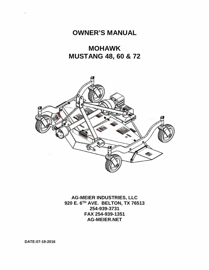
OWNER’S MANUAL
MOHAWK MUSTANG 48, 60 & 72
AG-MEIER INDUSTRIES, LLC 920 E. 6TH AVE. BELTON, TX 76513
254-939-3731 FAX 254-939-1351
AG-MEIER.NET DATE:07-19-2016

TABLE OF CONTENTS INTRODUCTION ........................................................................................................................1
ASSISTANCE .............................................................................................................................1
SAFETY ......................................................................................................................................2
SAFETY SIGNAL WORDS & SAFETY ALERT SYMBOL ...........................................................2
GENERAL SAFETY GUIDELINES ..............................................................................................3
SAFETY SIGN LOCATIONS .......................................................................................................4
SAFETY DECAL CARE ..............................................................................................................6
LIGHTING AND MARKING .........................................................................................................6
BEFORE OPERATION ...............................................................................................................7
DURING OPERATION ................................................................................................................8
HIGHWAY AND TRANSPORT OPERATIONS ...........................................................................9
FOLLOWING OPERATION.......................................................................................................10
PERFORMING MAINTENANCE ...............................................................................................11
HYDRAULIC FLUID AND EQUIPMENT SAFETY .....................................................................12
LOCKOUT/TAGOUT .................................................................................................................12
OPERATIONS ..........................................................................................................................16
MAINTENANCE ........................................................................................................................20
TROUBLE SHOOTING .............................................................................................................24
PARTS ......................................................................................................................................26
WARRANTY .............................................................................................................................32
BOLT TORQUE CHART ...........................................................................................................33
WARRANTY REGISTRATION FORM & INSPECTION REPORT .............................................35
`
1
INTRODUCTION Thank you for purchasing a Mohawk Mustang Finish Mower. We hope you will get many years of productive use from it. This mower is designed to be pulled by a ROPS protected tractor of proper size. This mower is designed to be used on small to medium grass in small pastures and large yards that are level to slightly sloping. All product users must read and understand this manual prior to equipment operation. This manual is considered part of your machine and should remain with the machine at all times. Do not allow anyone to operate or maintain this equipment that has not fully read and comprehended this manual. Failure to follow the recommended procedures may result in personal injury or death or equipment damage. Information in this manual is designed to help owners and operators to obtain the best results and safe operation from their investment. The life of any machine depends largely on the care it is given and we suggest that the manual should be read and understood and referred to frequently. If for any reason you do not understand the instructions and safety requirements, please contact your authorized dealer. The intent of this manual is to provide guidelines to cover general use and to assist in avoiding accidents and injuries. There may be times when circumstances occur that are not covered in the manual. At those times it is best to use common sense and contact your authorized dealer or our factory. The requirements of safety cannot be emphasized enough in this publication. We urge you to make safety your top priority when using and maintaining the equipment. We strongly advise that anyone allowed to operate this equipment be thoroughly trained and tested, to prove they understand the fundamentals of safe operation. Some photographs, diagrams or illustrations in this manual may show doors, guards and shields opened or removed to aid in clarity and understanding of a particular procedure. All guards, shields and safety devices must be in their proper position prior to operation.
ASSISTANCE If you have questions not answered in this manual, or require additional copies, or the manual is damaged, please contact your dealer or:
AG-MEIER IND. L.L.C. E-mail address 920 E. 6TH AVE. [email protected] BELTON, TX 76513 Phone 800 446 7319
`
2
SAFETY
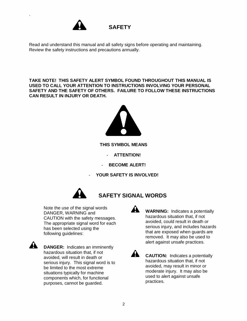
Read and understand this manual and all safety signs before operating and maintaining. Review the safety instructions and precautions annually. TAKE NOTE! THIS SAFETY ALERT SYMBOL FOUND THROUGHOUT THIS MANUAL IS USED TO CALL YOUR ATTENTION TO INSTRUCTIONS INVOLVING YOUR PERSONAL SAFETY AND THE SAFETY OF OTHERS. FAILURE TO FOLLOW THESE INSTRUCTIONS CAN RESULT IN INJURY OR DEATH.
THIS SYMBOL MEANS
- ATTENTION!
- BECOME ALERT!
- YOUR SAFETY IS INVOLVED!
SAFETY SIGNAL WORDS
Note the use of the signal words DANGER, WARNING and CAUTION with the safety messages. The appropriate signal word for each has been selected using the following guidelines:
DANGER: Indicates an imminently hazardous situation that, if not avoided, will result in death or serious injury. This signal word is to be limited to the most extreme situations typically for machine components which, for functional purposes, cannot be guarded.
WARNING: Indicates a potentially hazardous situation that, if not avoided, could result in death or serious injury, and includes hazards that are exposed when guards are removed. It may also be used to alert against unsafe practices.
CAUTION: Indicates a potentially hazardous situation that, if not avoided, may result in minor or moderate injury. It may also be used to alert against unsafe practices.
`
3
GENERAL SAFETY GUIDELINES
Safety of the operator and any bystanders is one of the main concerns in designing and developing a new piece of equipment. Designers and manufacturers build in as many safety features as possible. However, every year many accidents occur which could have been avoided by a few seconds of thought and a more careful approach to handling equipment. You, the operator, can avoid many accidents by observing the following precautions in this section. To avoid personal injury, study the following precautions and insist those working with you, or for you, follow them. Replace any CAUTION, WARNING, DANGER or instruction safety decal that is not readable or is missing. Location of such decals is indicated in this booklet. Do not attempt to operate this equipment under the influence of drugs or alcohol. Do not use the equipment if alertness or coordination is impaired. Review the safety instructions with all users annually. This equipment is dangerous to children and persons unfamiliar with its operation. The operator should be a responsible adult familiar with farm machinery and trained in this equipment’s operations. Do not allow persons to operate or assemble this unit until they have read this manual and have developed a thorough understanding of the safety precautions and of how it works. Do not read, eat, drink, talk or text or use a mobile phone while using this equipment. To prevent injury or death, use a tractor equipped with a Roll Over Protective System (ROPS). Do not paint over, remove or deface any safety signs or warning decals on your equipment. Observe all safety signs and practice the instructions on them. Never exceed the limits of a piece of machinery. If its ability to do a job, or to do so safely, is in question - DON’T TRY IT. Stay clear of any moving parts, such as shafts, couplings and universal joints. If adjustments need to be made, make them in small steps, shutting down all motions for each adjustment. Do not allow anyone to ride on any part of the equipment for any reason. Assure that all bystanders are at a safe distance before operating or maintaining this equipment.
`
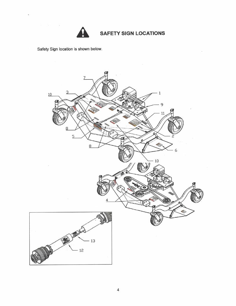
4
`
5
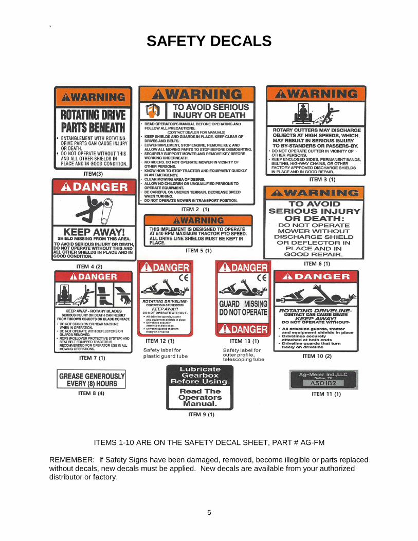
SAFETY DECALS
ITEMS 1-10 ARE ON THE SAFETY DECAL SHEET, PART # AG-FM REMEMBER: If Safety Signs have been damaged, removed, become illegible or parts replaced without decals, new decals must be applied. New decals are available from your authorized distributor or factory.
`
6
SAFETY DECAL CARE
• Keep safety signs clean and legible at all times.
• Replace safety signs that are missing or have become illegible.
• Replaced parts that displayed a safety sign should also display the current sign.
• Safety signs are available from your Distributor or Dealer Parts Department or the factory.
How to Install Safety Signs: • Be sure that the installation area is clean and dry.
• Decide on the exact position before you remove the backing paper.
• Remove the smallest portion of the split backing paper.
• Align the decal over the specified area and carefully press the small portion with the exposed sticky backing in place.
• Slowly peel back the remaining paper and carefully smooth the remaining portion of the decal in place.
• Small air pockets can be pierced with a pin and smoothed out using the piece of decal backing paper.
LIGHTING AND MARKING
• It is the responsibility of the customer to know the lighting and marking requirements of the local highway authorities and to install and maintain the equipment to provide compliance with the regulations. Add extra lights when transporting at night or during periods of limited visibility.
• Lighting kits are available from your dealer or from the manufacturer.
`
7
BEFORE OPERATION
• Carefully study and understand this manual.
• Do not wear loose-fitting clothing which may catch in moving parts.
• Always wear protective clothing and substantial shoes.
• Keep wheel lug nuts or bolts tightened to specified torque.
• Assure that agricultural implement tires are inflated evenly.
• Give the unit a visual inspection for any loose bolts, worn parts or cracked welds, and make necessary repairs. Follow the maintenance safety instructions included in this manual.
• Be sure that there are no tools lying on or in the equipment.
• Do not use the unit until you are sure that the area is clear, especially children and animals.
• Don’t hurry the learning process or take the unit for granted. Ease into it and become familiar with your new equipment.
• Practice operation of your equipment and its attachments. Completely familiarize yourself and other operators with its operation before using.
• Use a tractor equipped with a Roll Over Protective System (ROPS) and fasten your seat belt prior to starting the engine.
• The manufacturer does not recommend usage of tractor with ROPS removed.
• Move tractor wheels to the widest recommended settings to increase stability.
• Securely attach to towing unit. Use a high strength, appropriately-sized hitch pin with a mechanical retainer and attach safety chain.
• Do not allow anyone to stand between the tongue or hitch and the towing vehicle when backing up to the equipment.
`
8
DURING OPERATION
• Children should never be allowed on the equipment.
• Clear the area of small children and bystanders before moving the equipment.
• Shift towing unit to a lower gear before going down steep downgrades, thus using the engine as a retarding force. Keep towing vehicle in gear at all times. Slow down for corners and rough terrain.
• Make sure you are in compliance with all local and state regulations regarding transporting equipment on public roads and highways. Lights and slow moving signs must be clean and visible by overtaking or oncoming traffic when equipment is transported.
• SAFETY CHAIN - If equipment is going to be transported on a public highway, a safety chain should be obtained and installed. Always follow state and local regulations regarding a safety chain and auxiliary lighting when towing farm equipment on a public highway. Be sure to check with local law enforcement agencies for your own particular regulations. Only a safety chain (not an elastic or nylon/plastic tow strap) should be used to retain the connection between the towing and towed machines in the event of separation of the primary attaching system.
• Install the safety chain by crossing the chains under the tongue and secure to the draw bar cage or hitch or bumper frame.
• Beware of bystanders, particularly children! Always look around to make sure that it is safe to start the engine of the towing vehicle or move the unit. This is particularly important with higher noise levels and quiet cabs, as you may not hear people shouting.
• NO PASSENGERS ALLOWED - Do not carry passengers anywhere on, or in, the tractor or equipment, except as required for operation.
• Keep hands and clothing clear of moving parts.
• Always keep all shields and guards in place and securely fastened.
• Do not clean, lubricate or adjust your equipment while it is moving.
• When halting operation, even periodically, set the tractor or towing vehicle brakes, disengage the PTO, shut off the engine and remove the ignition key.
• Be especially observant of the operating area and terrain - watch for holes, rocks or other hidden hazards. Always inspect the area prior to operation.
− DO NOT operate near the edge of drop-offs or banks.
− DO NOT operate on steep slopes as overturn may result.
− Operate up and down (not across) intermediate slopes. Avoid sudden starts and stops.
`
9
HIGHWAY AND TRANSPORT OPERATIONS
• Adopt safe driving practices:
− Keep the brake pedals latched together at all times. NEVER USE INDEPENDENT BRAKING WITH MACHINE IN TOW AS LOSS OF CONTROL AND/OR UPSET OF UNIT CAN RESULT.
− Always drive at a safe speed relative to local conditions and ensure that your speed is low enough for an emergency stop to be safe and secure. Keep speed to a minimum.
− Reduce speed prior to turns to avoid the risk of overturning.
− Avoid sudden uphill turns on steep slopes.
− Always keep the tractor or towing vehicle in gear to provide engine braking when going downhill. Do not coast.
− Do not drink and drive!
• Comply with state and local laws governing highway safety and movement of farm machinery on public roads.
• Use approved accessory lighting flags and necessary warning devices to protect operators of other vehicles on the highway during daylight and nighttime transport. Various safety lights and devices are available from your dealer.
• The use of flashing amber lights is acceptable in most localities. However, some localities prohibit their use. Local laws should be checked for all highway lighting and marking requirements.
• When driving the tractor and equipment on the road or highway under 20 mph at night or during the day, use flashing amber warning lights and a slow moving vehicle (SMV) identification emblem.
• Plan your route to avoid heavy traffic.
• Be a safe and courteous driver. Always yield to oncoming traffic in all situations, including narrow bridges, intersections, etc.
• Be observant of bridge loading ratings. Do not cross bridges rated lower than the gross weight as which you are operating.
• Watch for obstructions overhead and to the side while transporting.
• Always operate equipment in a position to provide maximum visibility at all times. Make allowances for increased length and weight of the equipment when making turns, stopping the unit, etc.
`
10
• Pick the levelest possible route when transporting across fields. Avoid the edges of ditches or gullies and steep hillsides.
• Be extra careful when working on inclines.
• Maneuver the tractor or towing vehicle at safe speeds.
• Avoid overhead wires or other obstacles. Contact with overhead lines could cause serious injury or death.
• Avoid loose fill, rocks and holes; they can be dangerous for equipment operation or movement.
• Allow for unit length when making turns.
• Operate the towing vehicle from the operator’s seat only.
• Never stand alongside of unit with engine running or attempt to start engine and/or operate machine while standing alongside of unit.
• Never leave running equipment attachments unattended.
• As a precaution, always recheck the hardware on equipment following every 100 hours of operation. Correct all problems. Follow the maintenance safety procedures.
FOLLOWING OPERATION
• Following operation, or when unhitching, stop the tractor or towing vehicle, set the brakes,
disengage the PTO and all power drives, shut off the engine and remove the ignition keys.
• Store the unit in an area away from human activity.
• Do not park equipment where it will be exposed to livestock for long periods of time. Damage and livestock injury could result.
• Do not permit children to play on or around the stored unit.
• Make sure all parked machines are on a hard, level surface and engage all safety devices.
• Wheel chocks may be needed to prevent unit from rolling.
`
11
PERFORMING MAINTENANCE
• Good maintenance is your responsibility. Poor maintenance is an invitation to trouble.
Proper servicing and adjustments are key to the long life of any implement. With careful inspection and routine maintenance, costly downtime and repairs can be avoided.
• Some parts and assemblies can be quite heavy. Before attempting to unfasten any part or assembly, arrange to support it by means of a hoist, by blocking or by use of an adequate arrangement to keep it from falling, tipping, swinging or moving in any manner which may hurt somebody or damage the equipment.
• Always use lifting equipment that is adequately rated to do the job. Never lift equipment over people.
• Make sure there is plenty of ventilation. Never operate the engine of the towing vehicle in a closed building. The exhaust fumes may cause asphyxiation.
• Before working on the equipment, stop the towing vehicle, set the brakes, disengage the PTO and all power drives, shut off the engine and remove the ignition keys.
• Be certain all moving parts on attachments have come to a complete stop before attempting to perform maintenance.
• Always use a safety support and block the wheels. Never use a jack to support the equipment.
• Always use the proper tools or equipment for the job at hand.
• Use extreme caution when making adjustments.
• Never replace hex bolts with less than grade five bolts unless otherwise specified.
• After servicing, be sure all tools, parts and service equipment are removed.
• Where replacement parts are necessary for periodic maintenance and servicing, genuine factory replacement parts must be used to restore your equipment to original specifications. The manufacturer will not claim responsibility for use of unapproved parts and/or accessories and other damages as a result of their use.
• If equipment has been altered in any way from original design, the manufacturer does not accept any liability for injury or warranty.
• If repairs require the use of a torch or electric welder, be sure that all flammable and combustible materials are removed.
• Do not weld or cut on any tank containing oil, fuel or their fumes or other flammable material, or any container whose previous contents are unknown.
`
12
• Cleaning solvents should be used with care. Petroleum based solvents are flammable and present a fire hazard. Don’t use gasoline. All solvents must be used with adequate ventilation and their vapors should not be inhaled.
HYDRAULIC FLUID AND EQUIPMENT SAFETY
Only adequately trained and qualified persons should work on hydraulics systems. You may be severely injured or killed by being crushed under a falling piece of equipment. Always have transport locks in place and frame sufficiently blocked when working on any implement. Hydraulic fluid escaping under pressure can have sufficient force to cause injury. Keep all hoses and connections in good serviceable condition. Failure to heed may result in serious personal injury or death. Escaping hydraulic fluid under pressure can have sufficient pressure to penetrate the skin causing serious injury. Avoid the hazard by relieving the pressure before disconnecting lines or performing work on the system. Make sure hydraulic fluid connections are tight and all hydraulic hoses and lines are in good condition before applying pressure to the system. Use a piece of paper or cardboard, NOT BODY PARTS, to check for suspected leaks. Wear protective gloves and safety glasses or goggles when working with hydraulic systems. DO NOT DELAY! If an accident occurs, see a doctor familiar with this type of injury immediately. Any fluid injected into the skin or eyes must be treated within a few hours or gangrene may result. Always secure equipment with solid supports before working on or under it. Never work under equipment supported by hydraulics. Hydraulics can drop equipment if controls are actuated or hydraulic lines burst or pressure is lost while disconnecting lines. Either situation can drop machinery instantly even when power to hydraulics is off. Do not attempt to disconnect a hydraulic cylinder or hose while the system is under pressure! Check hydraulic hoses and fittings frequently. Brush and other debris can damage hoses and fittings. Inspect and maintain equipment daily. Loose, broken, and missing hardware can cause equipment to not perform properly and can result in bodily injury or death. Hydraulic systems and oil can be hot and cause burns. Before working on any system, wait until the oil has cooled.

`
13
LOCKOUT / TAGOUT
Think, plan and check. Think through the entire procedure and identify all the steps that are required. Plan what personnel will be involved, what needs to be shut down, what guards need to be removed, and how (and under what conditions) the power will be restarted. Check the machine over to verify all power sources and stored energy have been identified including engines, hydraulic and pneumatic systems, springs and accumulators, and suspended loads, Shutoff and lockout power before adjusting, servicing, maintaining, or clearing an obstruction from this machine. Failure to heed may result in serious injury or death. Communicate with everyone involved in a repair or maintenance operation, including bystanders, that work is being done which involves keeping this machine safety at a ZERO ENERGY STATE. OSHA’s requirements for lockout/tag out are covered in Section 1910.147 of the OSHA standards. The LOTO standard establishes the employer's responsibility to protect workers from hazardous energy. Employers are required to train each worker to ensure that they know, understand, and are able to follow the applicable provisions of the hazardous energy control procedures:
• Proper lockout/tag out (LOTO) practices and procedures safeguard workers from the release of hazardous energy. The OSHA standard for The Control of Hazardous Energy (Lockout/Tag out) for general industry, outlines specific action and procedures for addressing and controlling hazardous energy during servicing and maintenance of machines and equipment. Employers are also required to train each worker to ensure that they know, understand, and are able to follow the applicable provisions of the hazardous energy control procedures. Workers must be trained in the purpose and function of the energy control program and have the knowledge and skills required for the safe application, usage and removal of the energy control devices.
• All employees who work in the area where the energy control procedure(s) are utilized
need to be instructed in the purpose and use of the energy control procedure(s) and about the prohibition against attempting to restart or reenergize machines or equipment that is locked or tagged out.
• All employees who are authorized to lockout machines or equipment and perform the
service and maintenance operations need to be trained in recognition of applicable hazardous energy sources in the workplace, the type and magnitude of energy found in the workplace, and the means and methods of isolating and/or controlling the energy.
• Specific procedures and limitations relating to tagout systems where they are allowed.
• Retraining of all employees to maintain proficiency or introduce new or changed control
methods. OSHA outlines a six-step procedure for controlling hazardous energy:
• Step 1: Prepare for shutdown. It must be determined what type of power system is going to be deactivated including electrical, hydraulic, pneumatic or other energy sources. Knowledge of shut down methods is necessary.
`
14
• Step 2: Shutdown the equipment. This should be completed consistent with the manufacturer’s instructions for the shutdown procedure and could be a simple as placing a switch in the “off” position or pressing a button.
• Step 3: Isolate the equipment. This step involves closing of valves, throwing the main
disconnects or circuit breakers and disconnecting or capping any auxiliary power sources or secondary electrical systems.
• Step 4: Apply the lockout/tag out device. This is done to prevent restoration of the
flow of energy and is done at all disconnect switches, valves or other energy isolating devices. Locks are the preferred method of controlling energy and should be supplemented with tags. Various lockout devices are available including group lockout hasps. Locks should be individually assigned and have only one key.
• Step 5: Control the stored energy. This step includes the release, disconnect or
restraint of any residual hazardous energy which may be present and a check that all moving parts have stopped moving. It may also include the installation of “pancakes” or blanking of pipe flanges, the installation of ground wires to discharge electrical capacitors and the blocking or supporting of elevated equipment.
• Step 6: Verify isolation of equipment. Double-check the steps and verify that the
equipment indeed has been shut down and that the lock and tag do control the stored energy. Employees should be warned and the system tested, including pressing of all start buttons to assure that the equipment will not start.
`
15
Rotary Cutter Safe Practices Messages from the American Society of Agricultural and Biological Engineers
The following safe practices are recognized as being effective for enhancing safety, if followed, but may not be adequate, complete, or entirely applicable for every situation. They may not cover all possible hazardous situations; hence, they should be interpreted judiciously.
- Personal protective equipment such as, but not limited to, gloves, safety glasses, hard hat, and safety shoes should be worn when hazards to personal safety exist when operating mowers.
- Lower mower, disengage PTO, stop engine, remove key, de-energize hydraulics, set brake, and wait for all moving parts to stop before dismounting to park or service equipment.
- Securely support or block up before working underneath any lifted mower or component to avoid injury or death from inadvertent dropping due to hydraulic leak down, mechanical or hydraulic system failure, or inadvertent operation of controls.
- The tractor must be equipped with a roll-over protective structure (ROPS) except where the use of ROPS would create an additional hazard. The operator must fasten seat belt snugly prior to starting engine on tractors having ROPS in place. Avoid accidental fall-off or possible injury or death from tractor or equipment run-over by using seat belt during mowing operations.
- Operate the mower from the operator’s seat only. - Do not allow riders on the mower. - Do not allow rider on the tractor unless there is a seat belt-equipped position that is ROPS-
protected for each rider. - Visually check for hydraulic leaks and broken, missing, or malfunctioning parts, and make
necessary repairs. Do not use your hand to check for leaks: use cardboard or similar material. Escaping hydraulic oil under pressure can have sufficient force to penetrate the skin and cause a serious personal injury or death. The injected fluid may result in gangrene if the fluid is not surgically removed immediately by a doctor familiar with this form of injury.
- Before disconnecting hydraulic lines, release all hydraulic pressure. - Keep implement input driveline, implement input connection, and tractor PTO shield in
place and in good condition when operating. Be sure the driveline is securely locked onto the PTO.
- Do not open access doors or remove guards until rotating components have stopped. - Mowers that are provided with intake and/or discharge shield that may be subject to routine
wear or deterioration must be inspected regularly and maintained as instructed by the manufacturer in the operator’s manual.
- Make certain the slow moving vehicle (SMV) sign and other reflectors are clearly visible. Follow local traffic codes for slow moving vehicles when transporting on public roads.
- Attach safety chain between towed mower and propelling machine as shown in operator’s manual before towing on public roads.
`
16
OPERATION
TRACTOR PREPERATION BALLAST (FRONT END WEIGHT) Add enough weight to assure at least 20% of the tractors original weight is on the front wheels for safe transport. WHEEL TREAD Tractor wheel tread spacing should be increased when working on incline or rough ground to reduce the possibility of tipping. STABLIZER BARS OR SWAY BLOCKS Use stabilizer bars or sway blocks to prevent side sway of the mower. DRAFT LINKS The linkage to the lower draft links should be set in the “Float Position”, allowing the unit to Follow the contour of the terrain. DRAWBAR Shorten of remove drawbar so it will not interfere with the up and down movement of the mower. MOUNTING THE MOWER TO THE TRACTOR DANGER A crushing hazard exists when hooking-up equipment to a tractor. Do not allow
anyone to stand between tractor and implement while backing-up to implement. Do not operate hydraulic 3-point lift controls while someone is directly behind tractor near implement.
To mount the mower, be sure it is sitting on as level ground as possible and follow the steps outlined in the manual for attaching a three-point hitch implement. 1. Slowly back up to the mower while using tractor's 3-point hydraulic control to align lower 3-point arm holes with the hitch pins. 2. Engage tractor park break, shut tractor engine off, and remove key before dismounting from the tractor. 3. Attach the mower hitch pins to the lower three-point lift arms of the tractor. There are two sets of lower hitch holes on the mower. This allows for one length of driveline to be used for different types of tractors. The Mustang Mower should operate with the driveline neither fully collapsed nor extended beyond the separation of the safety shield. 4. Connect the tractor top link to the hole in the top of the pivot link of the mower. With the mower attached to the tractor’s three-point hitch, proceed to connection of the PTO as follows. 5. Slide the yoke with the quick disconnect pin onto the tractor PTO shaft. Move the yoke back and forth to insure it is locked onto the shaft. 6. Attach the safety chain to a stationary point to prevent the shield from spinning.
`
17
OPERATION 7. Return to the tractor and slowly raise and lower the mower to ensure that the drawbar, tires, and other equipment on the tractor do not make contact with the mower frame and driveline. Move or remove drawbar if needed. 8. Adjust the lower lift arms on the tractor to level the mower from left to right. 9. Adjust the top-link so that the pivot link slants backward approximately 15 degrees. IMPORTANT: CHECK DRIVELINE LENGTH A driveline that is too long can bottom out causing damage to the tractor and mower. Always check the driveline collapsed length during initial setup, when connecting to a different tractor, and when alternating between using a quick hitch and a standard 3-point hitch. Telescoping tubes must always overlap by at least 1/2 of their length in normal operations and at least 1/3 of their length in all working conditions. TRANSPORTING Pay particularly close attention to the SAFETY MESSAGES regarding mower transport. Avoid unnecessary injuries and equipment damage by exercising cautious and conscientious travel procedures. Attaching the mower to the tractor increases the overall length of the working unit. Allow additional clearance for the mower to swing when turning. Raise the mower as high as possible for transporting while maintaining clearance between the driveline and the deck of the mower. Tire pressure should be kept at around 20 PSI to decrease shock during transport. When using puncture-proof, laminated tires, be sure that the flat side of the lug nut is against the wheel. WARNING
When transporting the mower on a road or highway, use tractor warning lights, SMV sign, reflectors and other safety devices for adequate warning to the operators of other vehicles. Check the traffic regulations governing locale where mowing is to be done and work safely within those guidelines.
Be sure that the tractor lift lever is locked into the "transport" detent before attempting to transport the mower. Make sure that at least 20% of the tractor weight is on the front tires. WARNING
Hold transport speed to 15 mph, especially when using puncture-proof, laminated tires. These tires are designed for off road use only. They can be used on road surfaces at very low speeds for a short distance. Heat from pavement friction can build up causing the tire to ignite. The steel band holding the sections in place
could break, causing extensive damage to the mower and tractor as well as possible injury to the operator and passerby. When transporting up slopes with reduced front end weight the tailwheel should be lowered as far as possible to provide a stop if the tractor rears up.
`
18
OPERATION CUTTING HEIGHT ADJUSTMENT WARNING
Avoid personal injury. Be sure the tractor engine is off and the key is removed before making any adjustments. IMPORTANT: Avoid very low cutting heights. Striking the ground with the blades gives the most damaging shock loads a mower can encounter and will cause
damage to the mower and driveline. The mower should be operated at the highest position that will give desired cutting results. This will help prevent blades from striking the ground, reducing blade wear and undue strain on machine. 1. Raise mower off ground using tractor 3-point lift. SECURELY BLOCK MOWER IN POSITION
WARNING
THE MOWER CAN FALL FROM HYDRAULIC SYSTEM FAILURE. TO AVOID SERIOUS INJURY OR DEATH, SECURELY SUPPORT
MOWER BEFORE WORKING UNDERNEATH.
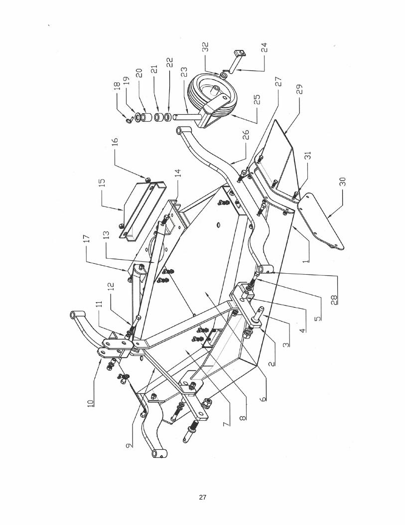
2. Remove pin securing the gauge wheel to arm. Remove the gauge wheel from arm. 3. Place amount of spacers on gauge wheel to give desired cutting height. With no spacers on the bottom, a 1-1/4" cutting height is given. ii 4. Reinstall gauge wheel into arm. Place remaining spacers on gauge wheel and install pin to retain. 5. Repeat operation for all gauge wheels. Make certain all wheels are adjusted to same height. IMPORTANT: When raising the mower to transport height, be sure there is clearance between the front of the deck and driveline. Damage will result if the driveline hits the mower deck. SIDE DISCHARGE OR REAR DISCHARGE The Mustang mower can be set up for side discharge or rear discharge. Side discharge will disperse the grass clipping easier therefore requiring less power. In heavy grass or wet grass, side discharge should be used. Rear discharge will provide better mulching of the grass clippings and may be used in lighter grass. For side discharge, remove the rear discharge cover, #30 on page 26, and bolt on the side discharge cover, #29. STARTING AND STOPPING THE MOWER Power for operating the mower is supplied from the tractor PTO. Refer to the tractor manual for instructions on engaging ad disengaging the PTO. Always engage the PTO at low engine RPM. Always operate at 540 RPM. Learn how to stop the tractor and mower quickly in case of an emergency. IMPORTANT: Stop the mower and the tractor immediately upon striking and obstruction. Inspect the mower and repair before resuming operation.

`
19
OPERATION WARNING
Avoid personal injury. When attempting to stop a tractor which does not have live PTO, the momentum created by the mower can cause the tractor to be pushed forward.
The installation of an overrunning clutch is recommended if the operating tractor does not have live power take off. See your dealer for additional information. To start operation, reduce engine speed and engage the tractor PTO. Before starting to cut, gradually increase engine speed to develop 540 RPM at the PTO. Enter the area to be cut with the mower operating at 540 RPM and, if it becomes necessary to temporarily regulate engine speed during operations, increase or decrease throttle gradually -never exceed 540 RPM. To transport, disengage the PTO and raise the machine to full transport height CUTTING SPEED Proper ground speed for the mower will depend upon the height, type and density of the material to be cut. Normally, ground speed will range from 2 to 5 mph. Tall dense material should be cut at low speed, while medium height material can be cut at a faster ground speed. CUTTING TIPS Always operate PTO at 540 RPM when cutting. This is necessary to maintain proper blade speed to produce clean cut. Under certain conditions, the tractor tires may roll some of the grass down and prevent it from being cut at the same height as the surrounding area. When this occurs, reduce the tractor ground speed, but maintain 540 PTO RPM. The lower speed will permit the grass to partially rebound and be cut. Taking a partial cut or reversing the direction of travel may also produce a cleaner cut.
WARNING Avoid personal injury. Pick up all rocks and other debris before cutting. Enter new areas carefully. Drive slowly and cut material higher the first time to allow the mower to clear unseen objects. Never assume an area is clear. Always check for hidden hazards.
Extremely tall grass should be cut twice. Raise the mower and cut twice the desired height. Cut the second time at the desired height at 90 degrees to the first pass. Remember, sharp blades produce cleaner cuts and use less power. Before cutting, study the area to determine the best cutting procedures. Consider the height and type of material and the terrain type: hilly, level, or rough. Avoid tractor rollovers: Be careful when operation the tractor and mower on uneven ground. Equip your tractor with a roll bar (ROPS) and seat belts. Keep seat belts tightened securely. In uneven terrain, rear wheel weights, front tractor weight and/or front tire ballast should improve stability. Pass diagonally through sharp dips and avoid drops to prevent "hanging up" the tractor and mower. Avoid sudden stops and starts while traveling up or down hills.
`
20
When cutting on slopes, always operate the mower in a downward motion and do not travel across the face of a slope. Avoid operation on steep slopes. Slow down on sharp turns to prevent tipping or loss of control.
MAINTENANCE MAINTANCE AND LUBRICATION Proper servicing and adjustments are the key to the long life of any machine. With careful and systematic inspection of the Mower, you can avoid costly maintenance, time and repair.
WARNING: For safety reasons, each maintenance operation must be performed with the PTO shaft disengaged, mower lowered completely to the ground or on safety supported blocking, the tractor engine shutoff and the ignition key removed.
AFTER THE FIRST HOUR AND AFTER 8 HOURS OF OPERATION: Check the belt tension. Check lubrication. Inspect for loose nuts and bolts. LUBRICATE DAILY:
1. PTO U-Joints & Profiles 3. Gauge wheel hub 2. Gauge wheel spindle tube 4. Blade rotors (every 8 hours)
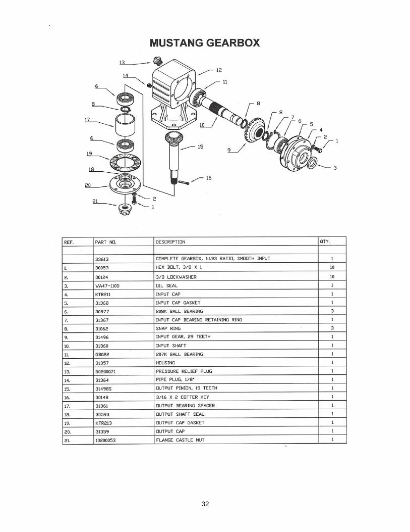
GEARBOX Lubricate every 50 hours of operation. On the Mustang, the flange mounted gearbox oil reserve is 26 ounces. If the oil reserve is below normal level, check for a crack in the gearbox or leaking seal. The oil must be checked after every 10 hours of operation. If oil flows out of the 1/8" oil level plug the proper lubrication level is being maintained. If oil does not flow out of the plug, add oil until it does. Recommended lubricant is SAE80w-90EP oil. Check the oil in the gearbox when the mower is level. DO NOT over fill the gearboxes. This will cause pressure to build up and cause oil seals to leak. UNIVERSAL JOINTS Grease fittings are located on the cross of each U-Joint, Grease after each 10 hours of use. DRIVELINE The telescoping PTO shaft inside the shielding must be lubricated daily. Disconnect the driveline from the tractor and pull the halves apart. Insert grease into the cavity on the half attached to the gearbox and spread evenly. Install the driveline halves together. Reconnect the driveline to the tractor. Raise and lower the mower after applying grease to spread over working joint area.
WARNING: When attaching the PTO yoke to the tractor PTO shaft, it is important that the spring activated locking pin is seated in the groove on the PTO shaft. A loose shaft could slip off and result in personal injury or damage to the mower.
`
21
MAINTENANCE
SERVICING CUTTING BLADES WARNING
Use only AG-MEIER INDUSTRIES LLC blades. They are made specifically for this mower. Substitute blades may not meet specifications and could be dangerous.
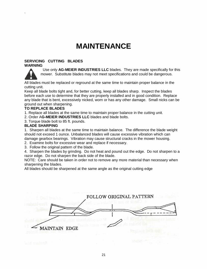
All blades must be replaced or reground at the same time to maintain proper balance in the cutting unit. Keep all blade bolts tight and, for better cutting, keep all blades sharp. Inspect the blades before each use to determine that they are properly installed and in good condition. Replace any blade that is bent, excessively nicked, worn or has any other damage. Small nicks can be ground out when sharpening. TO REPLACE BLADES 1. Replace all blades at the same time to maintain proper balance in the cutting unit. 2. Order AG-MEIER INDUSTRIES LLC blades and blade bolts. 3. Torque blade bolt to 85 ft. pounds. BLADE SHARPING 1. Sharpen all blades at the same time to maintain balance. The difference the blade weight should not exceed 1 ounce. Unbalanced blades will cause excessive vibration which can damage gearbox bearings. Vibration may cause structural cracks in the mower housing. 2. Examine bolts for excessive wear and replace if necessary. 3. Follow the original pattern of the blade. 4. Sharpen the blades by grinding. Do not heat and pound out the edge. Do not sharpen to a razor edge. Do not sharpen the back side of the blade. NOTE: Care should be taken in order not to remove any more material than necessary when sharpening the blades. All blades should be sharpened at the same angle as the original cutting edge
`
22
MAINTENANCE
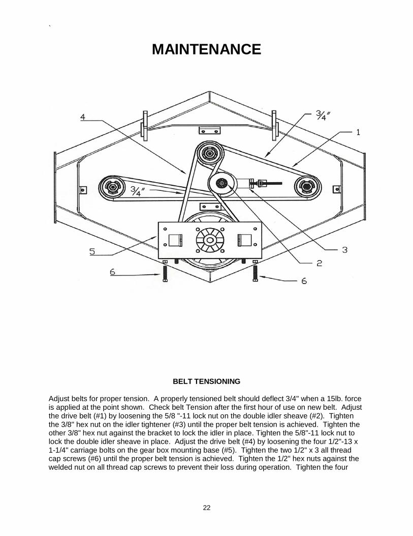
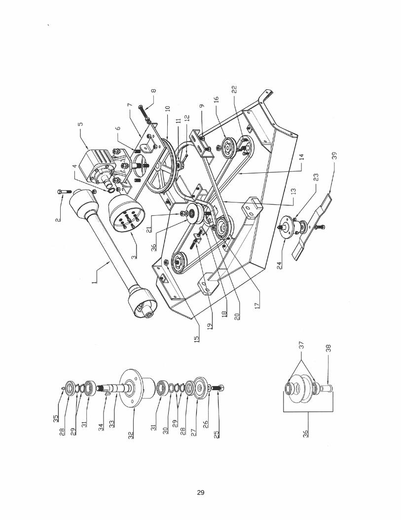
BELT TENSIONING
Adjust belts for proper tension. A properly tensioned belt should deflect 3/4" when a 15lb. force is applied at the point shown. Check belt Tension after the first hour of use on new belt. Adjust the drive belt (#1) by loosening the 5/8 "-11 lock nut on the double idler sheave (#2). Tighten the 3/8" hex nut on the idler tightener (#3) until the proper belt tension is achieved. Tighten the other 3/8" hex nut against the bracket to lock the idler in place. Tighten the 5/8"-11 lock nut to lock the double idler sheave in place. Adjust the drive belt (#4) by loosening the four 1/2"-13 x 1-1/4" carriage bolts on the gear box mounting base (#5). Tighten the two 1/2" x 3 all thread cap screws (#6) until the proper belt tension is achieved. Tighten the 1/2" hex nuts against the welded nut on all thread cap screws to prevent their loss during operation. Tighten the four

`
23
1/2"-13 x 1-1/4" carriage bolts on the gear box mounting base. Replace the hood safety shield at this time using the 3/8"-16 wing nuts provided.
`
24
` MAINTENANCE STORAGE Your mower represents an investment from which you should get the greatest possible benefit. Therefore, when the season is over, the mower should be thoroughly checked and prepared for storage so that a minimum amount of work will be required to put it back into operation for the next season. The following are the suggested storage procedures.
1. Thoroughly clean the mower
2. Lubricate the mower as covered in the Maintenance Section.
3. Tighten all bolts to recommended torque.
4. Check the mower for worn or damaged parts. Make replacements immediately using Genuine AG-MEIER IND. L.L.C.
5. Store the mower in a clean, dry place with the mower housing resting on blocks.
6. Use spray touch-up enamel where necessary to prevent rust and maintain appearance
of the mower.
`
25
TROUBLE SHOOOTING GUIDE
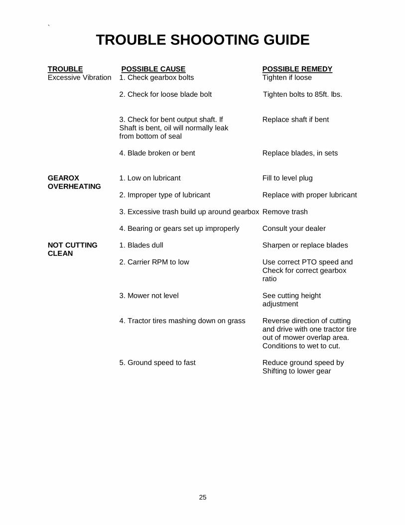
TROUBLE POSSIBLE CAUSE POSSIBLE REMEDY Excessive Vibration 1. Check gearbox bolts Tighten if loose 2. Check for loose blade bolt Tighten bolts to 85ft. lbs. 3. Check for bent output shaft. If Replace shaft if bent Shaft is bent, oil will normally leak from bottom of seal 4. Blade broken or bent Replace blades, in sets GEAROX 1. Low on lubricant Fill to level plug OVERHEATING 2. Improper type of lubricant Replace with proper lubricant 3. Excessive trash build up around gearbox Remove trash 4. Bearing or gears set up improperly Consult your dealer NOT CUTTING 1. Blades dull Sharpen or replace blades CLEAN 2. Carrier RPM to low Use correct PTO speed and Check for correct gearbox ratio
3. Mower not level See cutting height adjustment 4. Tractor tires mashing down on grass Reverse direction of cutting and drive with one tractor tire out of mower overlap area. Conditions to wet to cut. 5. Ground speed to fast Reduce ground speed by Shifting to lower gear

`
26
TROUBLE SHOOOTING GUIDE
TROUBLE POSSIBLE CAUSE POSSIBLE REMEDY STREAKING 1. Conditions to wet for cutting. Blades Allow grass to dry before CONDITIONS unable to cut that part of grass pressed cutting. Slow ground speed Down by path or tractor tires of tractor but keep engine at full PTO RPM. Cutting lower may help. 2. Dull blades Sharpen or replace blades GEARBOX 1. Rough gears Run in or change gears NOISY 2. Worn bearings Replace bearings GEARBOX 1. Damaged oil seal Replace seal LEAKING 2. Bent shaft Replace oil seal & shaft 3. Oil seal installed wrong Replace seal 4. Oil level to high Drain oil to proper level 5. Pin hole leak in gearbox housing Replace housing or gearbox 6. Gasket damaged Replace gasket 7. Bolts loose Tighten bolts SHEAR PIN 1. Tractor PTO not being run at 540 RPM Run at 540 RPM SHEARS EXCESSIVELY 2. Heavy Material Reduce ground speed. raise cutting height 3. Not using proper pin Replace, only with recommended pin BLADE WEAR 1. Cutting in sandy conditions Increase cutting height. keep TO FAST blade at least 1-1/4" above the ground. 2. Cutting in rocky conditions Increase cutting height
`
27

`
28
`
29

`
30
`
31
`
32
`
33
WARRANTY AG-MEIER INDUSTRIES LLC warrants to the original purchaser of new AG-MEIER INDUSTRIES LLC Product, that they are free for defects in material and workmanship. This warranty is applicable only for normal life expectancy of the unit or individual components for a period of one year from the date of original purchase if for personal use; 90 days for commercial or rental purposes. Warranty coverage is limited to replace any part, at no charge to the original purchaser that, in our judgment, shows evidence of defect: provided that upon written request, any such defective part is returned to AG-MEIER INDUSTRIES LLC within 30 days of failure. This Warranty does not apply to any part or product which in AG-MEIER INDUSTRIES LLC judgment has been subjected to negligence, alteration, or modification. Equipment that has been damaged due to lack of proper maintenance or use of wrong oil or lubricants, or that has been used for a purpose for which the product is not designed is also excluded from the Warranty. For maximum safety and to guarantee optimum product reliability, always use genuine AG-MEIER INDUSTRIES LLC parts. The use of replacement parts manufactured by companies other the AG-MEIER INDUSTRIES LLC invalidates this Warranty. Claims under the warranty must be made to the dealer which originally sold the product. AG-MEIER INDUSTRIES LLC reserves the right to make changes in material or design of the product at any time without notice. This Warranty shall not be interpreted to render AG-MEIER INDUSTRIES LLC liable for damages of any kind; direct, consequential, or contingent, to property. Furthermore, AG-MEIER INDUSTRIES LLC shall not be liable for damages resulting from any cause beyond its reasonable control. This Warranty does not extend to any expense due to loss for labor, supplies, rental machinery or for any other reason. This Warranty does not apply to any part of any internal combustion engine, driveline component, or expendable items such as blades, shields, guards, or tires as specifically found in the Operator's Manual. Except as provided herein, no employee, agent, Dealer or other person is authorized to give any warranties of any nature of behalf of AG-MEIER INDUSTRIES LLC. This Warranty is not effective unless the Purchaser returns the Registration Form to the Manufacturer within 30 days of purchase. No other warranty of any kind whatsoever, express of implied, is made with respect to this sale; and all implied warranties of merchantability and fitness for particular purpose which exceed the obligations set forth in this written Warranty are hereby disclaimed and excluded from this sale. If any provision of this limited Warranty shall violate any applicable law, and is held to be unenforceable, then the invalidity of such provision shall not invalidate any other provision herein. MUSTANG MODEL # _________________________________ MUSTANG SERIAL MODEL # _________________________________

`
34
Blade Bolt 85 ft-lbs

`
35

`
36
WARRANTY REGISTRATION FORM & INSPECTION REPORT
WARRANTY REGISTRATION This form must be filled out by the dealer and signed by both the dealer and the customer at time of delivery.
Customer name ________________________ Dealer name ___________________________
Address ______________________________ Address ______________________________
City, state, code ________________________ City, state, code ________________________
Phone number (_________ ) ______________
Model ____________________ Serial Number _____________ Delivery date _____________
DEALER: I hereby certify that: I have thoroughly instructed the buyer on the above-described equipment; review including the operator’s manual content, equipment care, adjustments, safe operation and applicable warranty policy. All decals are installed and are in good repair. Driveline, gearbox, and shields are in good repair and fastened securely in place to prevent injuries from entanglement or thrown objects. All bolts have been checked and tightened. Date __________________ Dealer’s signature _____________________________ The above equipment and operators manual have been received by me, and I have been thoroughly instructed as to the care, adjustments, safe operation and applicable warranty policy . I have examined the equipment and accept it in complete and satisfactory condition . I have also examined all the warning/safety decals and understand the dangers of unauthorized repairs and alterations of the product . I further understand that attempting to operate this product outside of the specified design parameter will void the warranty as stated in the operating manual . I also understand that this warranty is considered null and void if I use any replacement parts other than those approved by AG-MEIER IND. All warranty work MUST BE APPROVED by AG-MEIER IND. BEFORE any replacement or labor costs will be reimbursed. Date __________________ Owner’s signature _____________________________

`
37
AG-MEIER INDUSTRIES, LLC 920 E. 6TH AVE.
BELTON, TX 76513