OWNERS MANUAL - EcoWaterecowater.bg/assets/Uploads/en/Ecowater IF.pdf · (default minutes) Fill...
26
SERIES ETF2100 --- IF10 with potassium permanganate feeder Version 10--2005 ® Manufactured by EcoWater Systems PO Box 64420, St. Paul MN 55164---9888 Part No. 7260033 EURO (Rev. A 9/2/04) OWNERS MANUAL How to maintain and operate your EcoWater automatic iron filter system
Transcript of OWNERS MANUAL - EcoWaterecowater.bg/assets/Uploads/en/Ecowater IF.pdf · (default minutes) Fill...

SERIESETF2100 --- IF10
with potassium permanganate feeder
Version 10--2005
®
Manufactured by EcoWater SystemsPO Box 64420, St. Paul MN 55164---9888 Part No. 7260033 EURO (Rev. A 9/2/04)
OWNERSMANUAL
How to maintain and operate yourEcoWater automatic iron filter system

2
ECOWATERS Y S T E M S Unpacking, Table of Contents
UNPACKING
The EcoWater Automatic Iron Filter is shipped fromthe factory in two cartons, consisting of. . .... mineral tank assembly & controller cover, timerand valve assembly & small parts skin--pack in onecarton, and... solution feeder tank, check valve assembly,nozzle assembly and connecting parts & 2.1 mlength of 5/16 in. O.D. tubing & 2.1 m length of 3/8in. O.D. tubing in the second carton.NOTE: Gravel underbedding is included in the tank.Filtering mineral and sand are not included. Seepages 23 and 24 for parts ordering information.Thoroughly check the filter for possible shippingdamage and parts loss. Also inspect and note anydamage to the shipping cartons. Notify the trans-portation company if damage is present. EcoWateris not responsible for in--transit damages.Remove and discard (RECYCLE) all packing materi-als. We suggest you do not remove the small partson the skin--pack until you are ready to use them. Fil-ter assembly instructions are on pages 5 thru 11.Flow Washer Usage
Tank Size
Media 10”
Birm 5 gpm (18.9 l/min)
Greensand 7 gpm (26.5 l/min)
TABLE OF CONTENTS
Page
Specifications / Dimensions 3
Planning Installation 4 -- 5
Assembly / Installation 5 -- 11
Programming Face Plate Timer 12 -- 13
Features / Options 13 -- 14
Filter Operation 15 -- 18
Maintenance 19 -- 20
Wiring Schematic 20
Service Information 21 -- 22
Repair Parts 23 -- 26
European Directive 2002/96/EC requires all electrical and electronicequipment to be disposed of according to Waste Electrical and Electronic Equipment(WEEE) requirements. This directive or similar laws are in place nationally and can varyfrom region to region. Please refer to your state and local laws for proper disposal of thisequipment.

3
ECOWATERS Y S T E M S Specifications / Dimensions
ETF2100IF1010” dia. x 47” Resin Tank
FILTER TYPE
Iron Removal (Mineral )Birm (Ferrite) or, Manganese Treated
Greensand
Iron Removal Limits (parts per million) 20
Amount Mineral Recommended (cu ft) 1 to 1--1/4 (28.3 -- 35.4 litres)
Amount Gravel (Kg) 7.7
Amount Filter Sand Recommended (Kg) 4.5
Supply Water Pressure Limits (Bar) 1.4 -- 8.6
Supply Water Temperature Limits (_C) 4.5 -- 49
Minimum Inlet Water Flow -- Backwash and Fast Rinse Flow ToDrain -- (l/min) 19
Mineral Regenerant Potassium Permanganate
Amount Regenerant Used Each Recharge (ml) 60
order mineral and sand separately (not included with filter)ferric iron, ferrous iron, or a combination of both
127 cm145 cm
30cmDIA.
9.5 cm
46 cm
35.5 cm
35.5 cmRECHARGE CYCLE TIMES
(default minutes)
Fill 1:30Brine Draw 80Backwash 20Fast Rinse 5
FOR FUTURE REFERENCE, ENTERTHE FOLLOWING INFORMATION
MODEL NO. ¡
DATE CODE ©
SERIAL NO. ¡
INSTALLATION DATE
IRON CONTENT PPM
¡ on rating decal© on shipping carton

4
ECOWATERS Y S T E M S Planning Installation
INLET -- OUTLET PLUMBING OPTIONS
S ALWAYS INSTALL an EcoWater bypass valve,#77214383 or a 3 valve bypass system.
S Use 1”... or, 3/4” (minimum) pipe and fittings.
S Use sweat copper... or, threaded pipe*... or,CPVC plastic pipe.*
*Sweat soldering is required to adapt to the fittings(1” male) supplied with the filter, or obtain approvedcompression adaptors. PVC plastic adaptors, part#7104546, are available from EcoWater. Be sure tocomply with all local plumbing codes.
OTHER REQUIREMENTS
S A drain is needed for regeneration discharge wa-ter. A floor drain is preferred, close to the filter. Alaundry tub, sump, standpipe, etc., are otherdrain options.
CAUTION: Drain water exits the hose at a fast flowrate, and at water system pressure. BE SURE thehose is fastened at the drain point in some man-ner to prevent ‘‘whipping’’, and splashing is con-tained to prevent damage to the surrounding area.
S a 220 -- 240 VAC / 50Hz, grounded electrical out-let (continuously ‘‘live’’) is needed within 2 me-ters of the filter.
TOOLS YOU MAY NEED
D common screwdriver D pliers
D cross---point screwdriver D tape measure
SOLDERED COPPER THREADED CPVC PLASTIC
D tubing cutter D hacksaw orpipe cutter
D hacksaw
D propane torch D threadingtool
D adjustablewrench
D LEAD---FREEsolder and flux
D pipe jointcompound*
D solvent ce-ment*
D emery cloth,sandpaper orsteel wool
D primer
* approved for use on potable water
MATERIALS YOU MAY NEED
H bypass valve, or 3 valvesH pipe and fittings as requiredH 5/8” I. D. minimum drain hose, either standard gar-den hose, or hose onto a barb fitting
VALVE DRAIN OPTIONS: Flexible drain hose isnot allowed in all localities (check your codes). Fora rigid valve drain run, plumb in following codes. Toadapt to the valve drain fitting, purchase a gardenhose thread x 5/8” tube (minimum) adaptor.
SELECT INSTALLATION LOCATION
Consider all of the following as an installation loca-tion for the filter is selected.
S To filter all water in the home, install the filterclose to the water supply inlet, and before all oth-er plumbing connections, EXCEPT outside wa-ter pipes. Outside faucets should remain on rawsupply water.
S Always install a water softener along with theiron filter. Locate the filter ahead of the softener,and both ahead of the water heater as shown inFigure 21, page 5.
S If other water conditioning equipment is needed,locate as shown in Figure 21, page 5.
S A nearby drain is needed to carry away regen-eration discharge water. A floor drain is pre-ferred, with a laundry tub, sump, standpipe, etc.,other options (check your local codes).
S The filter works on 24 VAC volts only. A trans-former is included to reduce 220 --240 VAC / 50Hz house electrical power. Provide an approved,grounded outlet within 2 meters of the filter. Thetransformer has an attached 2 meters powercable for connection between the outlet and thetimer.
S Position the filter at least 15 cm from surround-ing walls, or other appliances, to allow access foradding potassium permanganate powder, andother service.
S Install the filter in a place water damage is leastlikely to occur if it develops a leak.
S If installing the filter in an outside location, besure to provide protection from the elements,contamination, vandalism, and sunlight heat.The sun’s heat can melt plastic parts.

5
ECOWATERS Y S T E M S Planning Installation
WaterSoftener
Taste & OdorFilter
AUTOMATICIRON FILTER
NeutralizerFilter
SedimentFilter
PressureTank
city water supply
well water supply
OR
WellPump
WaterHeater
outsidefaucets
conditioned cold
conditioned hot
COMPLETE WATER CONDITIONING SYSTEM -- Seldom would all of the water conditioners shown below be neededon one water supply. The drawing shows the proper sequence location for each conditioner relative to the others.
FIGURE 21
Note: For clarity, not all EcoWater conditioners are illustrated (reverse osmosis, distillers, other drinking water).
ECOWATERS Y S T E M S Assembly / Installation
3. FILL MINERAL TANK, INSTALL VALVE
d. Remove the tank clamps (Figure 22, page 6),valve assembly, o--ring seals (3), and the top distrib-utor.
e. Shake the tank to level the factory loaded gravel.Temporarily plug the bottom distributor standpipewith a rag to prevent sand and mineral from entering.
f. Move the tank to the installation location. Using afunnel, add the specified amount of filter sand. Then,add the mineral.
NOTE: Filter sand and the desired mineral type arenot included with the filter (see specifications).
g. Thoroughly clean all sand and mineral from thetank top opening. Fill the tank with water, 2.5 to 5 cmfrom the top.
h. Pour about 30 ml (2 tablespoons) of disinfectantinto the iron filter. Add through the tank top opening.
i. Install the top distributor and three o-ring seals inthe tank exactly as shown in Figure 22, page 6.
j. Lower the valve assembly onto the tank, centeringover the standpipe. Push downward, to squeeze theo-ring seals, while installing the clamp sections andretainers. Be sure the clamp sections and retainersare fastened securely in place.
Care is taken at the factory to keep your water filterclean and sanitary. Materials used to make the filterwill not infect or contaminate your water supply, andwill not cause bacteria to form or grow. However,during shipping, storage, adding mineral, installingand operating, bacteria could get into the filter. Forthis reason, sanitizing as follows is suggested ¡
when installing.
Common 5.25% household bleach such as Clorox,Linco, Bo Peep, White Sail, Eagle, etc., is a sug-gested disinfectant. Another is tablet or granularform calcium hypochlorite, under trade names suchas Perchloron and HTH.
¡ Recommended by the Water Quality Association. On somewater supplies, the filter may need periodic disinfecting.
SANITIZING THE FILTER

6
ECOWATERS Y S T E M S Assembly / Installation
FIGURE 22
standpipe
top distributor
resintank
valveassembly
clamp retainer (2)
clamp section (2)
o--- ring,13/16” x 1---1/16”
o--- ring,2---7/8” x 3---1/4”
(thick)
o--- ring,2---3/4’ x 3”
(thin)
standpipe
4. NOZZLE ASM., FEEDER VALVE & TANK
a. Push the rubber grommet into the 2 cm dia. holein the feeder tank sidewall. Then, insert the hoseadaptor elbow into the grommet.
b. Using Figure 23 as a guide, connect the nozzle &venturi assembly to the feeder brine valve assemblyusing the connector.
c. Check to be sure all compression nuts are tight-ened and the brine valve is vertical.
FIGURE 23
connector,with nut
nozzleassembly
hose adaptor& grommet
cover
brinevalve feeder tank
5. INSTALL INLET AND OUTLET FITTINGS
NOTE: All fittings are on the small parts skin--pack.
a. Insert the support into the valve outlet port (pushin firmly), up to the shoulder.
NOTE: If installing the EcoWater bypass valve, seeFigure 24, or the separate instructions included withit. If the bypass has a bleed screw, make sure it iscompletely closed
b. Slide a lubricated o--ring seal onto one of the cop-per tubes. Carefully insert the copper tube into theoutlet port (see Figure 24) and secure in place witha plastic ‘‘C’’ clip.
NOTE: For lubrication, use silicone grease ap-proved for use on potable water supplies.
c. Repeat step b on the INLET port side.
IMPORTANT: Be sure copper tubes are firmly heldin place by the plastic ‘‘C’’ clips.
FIGURE24
copper tube o--- ring
clip support
VALVE INLET
o--ring seal (2)
1” copper tube (2)
clip (2)
turbine support
6. TURN OFF WATER SUPPLY
a. Close the main water supply valve, near the wellpump or water meter.
b. Shut off the electric or fuel supply to the waterheater.
c. Open high and low faucets to drain all water fromthe house pipes.

7
ECOWATERS Y S T E M S Assembly / Installation
7. INSTALLING THREE VALVE BYPASS
If installing a 3--valve bypass system, plumb asneeded using Figure 27 on page 9 as a guide.When installing sweat copper, be sure to use lead--free solder and flux, as required by federal andstate codes. Use pipe joint compound on outsidepipe threads.
8. MOVE THE FILTER INTO PLACE
Move the filter into installation position. Set it on asolid, smooth and level surface. If needed, place thefilter on a section of 2 cm (minimum) plywood. Then,shim under the plywood to level the filter, Figure 25.
CAUTION: Do not place shims directly under theshroud. The weight of the tank may cause the tankto fracture at the shim.
FIGURE25
shroud
2 cm plywoodshim
9. ASSEMBLE INLET & OUTLET PLUMBING
Measure, cut, and loosely assemble pipe and fittingsfrom the main water pipe (or from the bypass valvesinstalled in step 7), to the inlet and outlet coppertubes, on the filter.
Be sure the HARD WATER supply pipe GOES TOthe filter INLET SIDE. Trace the water flow directionto be sure.
10. COLD WATER PIPE GROUNDING
The house cold water pipe (metal only) is often usedas a ground for the house electrical system. The3--valve bypass type of installation, shown in Figure27 on page 9, will maintain ground continuity. If youuse the plastic bypass valve at the filter, continuity isbroken. To restore the ground, do either step a or bfollowing (see Figure 26).
a. Use the clamps and wire, to make a jumper acrossthe inlet and outlet copper tubes.
b. Install a #4 copper wire across the removed sec-tion of main water pipe, securely clamping at bothends.
ground wire
clamp, screwand nut (2)
FIGURE26 Install hose clamps before
soldering copper tubes
coppertubes
clamp,ground (2) ground wire

8
ECOWATERS Y S T E M S Assembly / Installation
11. CONNECT INLET & OUTLET PLUMBING
Complete the inlet and outlet plumbing as applicablebelow.
a. SOLDERED COPPER
(1) Thoroughly clean and flux all joints.
(2) Pull the plastic ‘‘C’’ clips and remove the inlet andoutlet tubes from the valve, and the o--rings from thetubes. DO NOT solder with tubes in the valve. Sol-dering heat will damage the valve.
NOTE: If installing ground as shown in Figure 26,place hose clamps on copper tubes (see step 10a).
(3) Make all solder connections. Be sure to keep fit-tings fully together, and pipes square and straight.
(4) After plumbing has cooled, repeat steps 5band 5c, page 6.
IMPORTANT: Be sure copper tubes are firmly heldin place by the plastic ‘‘C’’ clips.
b. THREADED PIPE
(1) Apply pipe joint compound to all outside pipethreads.
(2) Tighten all threaded joints.
(3) If soldering to the inlet and outlet tubes, observestep a above.
c. CPVC PLASTIC PIPE
(1) Clean, prime and cement all joints, following themanufactures instructions supplied with the plasticpipe and fittings.
(2) If soldering to the inlet and outlet tubes, observepreceding step a.
12. INSTALL VALVE DRAIN HOSE
a. Connect a length of 5/8” minimum I.D. hose(check codes) to the valve drain elbow, on the con-troller, Figure 28. The elbow accepts either hoseonto a barb fitting, or standard garden hose. To usethe threads, cut off the barbs with a hacksaw.
b. Run the hose to the floor drain, and as typicallyshown in Figure 28, tie or wire the end to a brick orother heavy object. This will prevent ‘‘whipping’’ dur-ing regenerations. Be sure to provide a 4 cm mini-mum air gap, to prevent possible sewer water back-up.
NOTE: In addition to the floor drain, you can use alaundry tub, sump, or standpipe as a drain point (see“Other Requirements” on page 4). Be sure to avoidlong drain runs, or elevating the hose, which restrictdrain flow.

9
ECOWATERS Y S T E M S Assembly / Installation
TYPICAL VALVE INSTALLATIONS
INLET --- OUTLET OPTIONS
1” copper tube(2 supplied)
1’ x 1” strgt.sweat connector
1’ x 3/4” strgt.sweat connector
1” sweat x 1” or 3/4”pipe thread
120V, 60Hzoutlet
INLETINLET
OUTLET
OUTLET3--- valve
bypass system
inlet valve
outlet valve
bypass valve
HARDWATER
HARDWATER
CONDITIONEDWATER
FIGURE 27
EcoWaterbypass valve#7214383
NOTE: Controller coverand timer not shown forclarity of drawing.
Tie or wire valve drainhose in place, to keepover floor drain.
220---240 VAC/ 50 Hz outlet
transformer(supplied)
to timer
INLET
OUTLET
HARDWATER
CONDITIONEDWATER
TUBING INSTALLATION
floor drain4 cmairgap
supply saddle valve,softened water
overflow hose
valve drain hose
READ THE SAFETYGUIDES, PAGE 3
SOFTENER
FIGURE 28

10
ECOWATERS Y S T E M S Assembly / Installation
13. INSTALL CONDITIONED WATERSUPPLY SADDLE VALVE
NOTE: If plumbing codes do not allow saddlevalves, provide fittings for connection as typicallyshown in Figure 29B.
To protect yourself from serious injury orfatal shock, use a hand or battery powereddrill only to do the following step. Do notuse an electric drill.
DANGER
a. In a nearby, convenient location, drill a 6 mm dia.hole into a conditioned, cold water pipe.
b. Install the included saddle valve as shown in Fig-ure 29A. Tighten screws evenly, but do not overtigh-ten. Be sure to use the rubber gasket. Fully openthe valve.
FIGURE29
A SADDLE VALVEINSTALLED
gasket
drill 6 mmhole for pin
sweatreducer1/2 x 1/4 FPT
B TYPICAL OPTION
includedshutoff valve
tee 3/4 x3/4 x 1/2
3/4” copperpipe (existing)
14. MAKE ALL TUBING CONNECTIONS
Move the feeder assembly into place nearby the fil-ter, keeping accessible for adding potassium per-manganate powder and other service.
Make all tubing connections as shown in Figure 30.Be sure to allow enough tubing length to permit cov-er installation. Tighten all compression nuts. Do notkink or bend the tubing.
a. 5/16” O.D. -- from conditioned water saddle valve(installed in step 9), to the bottom of solenoid valve.
b. 5/16” O.D. -- from bottom of the nozzle/venturi, totop of solenoid valve.
c. 3/8” O.D. -- from top of the nozzle/venturi, to 3/8”tube adaptor. Make sure adaptor is in proper posi-tion, see Figure 30.
d. 3/8” I.D. high quality hose -- from hose adaptor onthe feeder tank to a floor drain -- Be sure to providean air gap between the end of the hose and floordrain (Figure 28, page 9).
CAUTION: Do not omit this hose. It will carry ex-cess potassium permanganate solution to the floordrain if the tank should over fill. Permanganatesolution will deeply stain.
FIGURE 30
Y
L
xx
Y
nozzle &venturi
solenoid valve
saddlevalve
L
xadaptor must beassembled with
tab down
a. 5/16”
b. 5/16”
c. 3/8”
J
J
brass compression Y
5/16” compression
3/8” tubing fitting
5/16” to threaded adaptor
11
ECOWATERS Y S T E M S Assembly / Installation
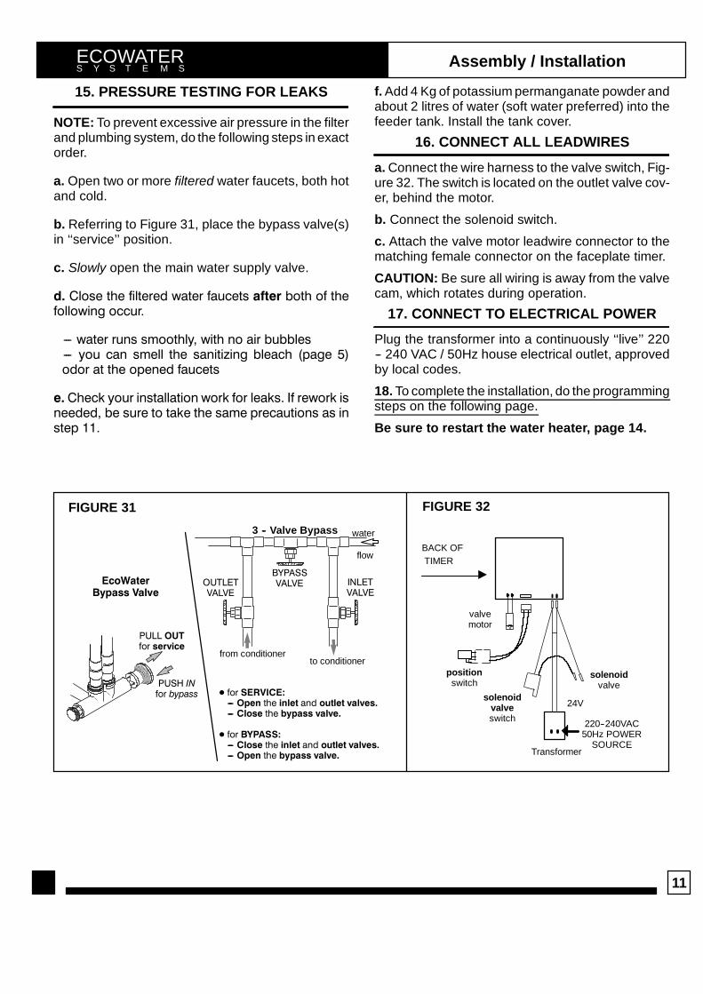
15. PRESSURE TESTING FOR LEAKS
NOTE: To prevent excessive air pressure in the filterand plumbing system, do the following steps in exactorder.
a. Open two or more filtered water faucets, both hotand cold.
b. Referring to Figure 31, place the bypass valve(s)in ‘‘service’’ position.
c. Slowly open the main water supply valve.
d. Close the filtered water faucets after both of thefollowing occur.
--- water runs smoothly, with no air bubbles--- you can smell the sanitizing bleach (page 5)odor at the opened faucets
e. Check your installation work for leaks. If rework isneeded, be sure to take the same precautions as instep 11.
f. Add 4 Kg of potassium permanganate powder andabout 2 litres of water (soft water preferred) into thefeeder tank. Install the tank cover.
16. CONNECT ALL LEADWIRES
a. Connect the wire harness to the valve switch, Fig-ure 32. The switch is located on the outlet valve cov-er, behind the motor.
b. Connect the solenoid switch.
c. Attach the valve motor leadwire connector to thematching female connector on the faceplate timer.
CAUTION: Be sure all wiring is away from the valvecam, which rotates during operation.
17. CONNECT TO ELECTRICAL POWER
Plug the transformer into a continuously ‘‘live’’ 220-- 240 VAC / 50Hz house electrical outlet, approvedby local codes.
18. To complete the installation, do the programmingsteps on the following page.
Be sure to restart the water heater, page 14.
Transformer
24V
positionswitch
BACK OFTIMER
"
220--240VAC50Hz POWER
SOURCE
3 -- Valve Bypass
OUTLETVALVE
INLETVALVE
BYPASSVALVE
to conditionerfrom conditioner
D for SERVICE:--- Open the inlet and outlet valves.--- Close the bypass valve.
D for BYPASS:--- Close the inlet and outlet valves.--- Open the bypass valve.
EcoWaterBypass Valve
water
flow
PUSH INfor bypass
PULL OUTfor service
valvemotor
FIGURE 31 FIGURE 32
solenoidvalveswitch
solenoidvalve

12
ECOWATERS Y S T E M S Programming Face Plate Timer
FIGURE 33DOWN keypadUP keypaddisplay
SELECT keypadRECHARGE keypad
VACATION
NOW (HOLD)
V. When the transformer is plugged in, the modelcode HIF10 shows in the face plate display for thefirst few seconds. The model code is followed by atest number (example: J1.0). Then the display willflash “12:00 PM” and the words “PRESENT TIME”.Set the present time of day as follows:
D. Set Time of Day
1. Press the UP or DOWN keypads until the correcttime of day shows, being sure AM or PM shows in thedisplay.
NOTE: Press and quickly release the keypads toslowly advance the display. Hold the kaypads down
for fast advance. This procedure applies for all fol-lowing settings.
2. Press the SELECT keypad once to set the presenttime and advance to the next set up screen.
E. Set Days to Recharge
1. This setting is the number of days the filter will gobetween recharges. The default setting is 3 days,with a maximum setting of 99.
2. Press the UP or DOWN keypads until the correctnumber of days between recharges is shown in thedisplay.
3. Press the SELECT keypad once to set the daysto recharge and advance to the next set up screen.
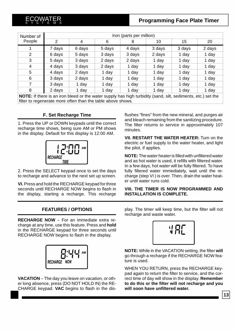
NOTE: See the chart on the following page to deter-mine the frequency of recharges. Find the numberof people living in the household, and then goingacross the chart, find the amount of iron (in parts permillion) that is in the water supply. The number ofdays that shows is the number of days the filtershould be set for recharges.
13
ECOWATERS Y S T E M S Programming Face Plate Timer
Number of Iron (parts per million)Number ofPeople 2 4 6 8 10 15 20
1 7 days 6 days 5 days 4 days 3 days 3 days 2 days2 6 days 5 days 3 days 3 days 2 days 1 day 1 day3 5 days 3 days 2 days 2 days 1 day 1 day 1 day4 4 days 3 days 2 days 1 day 1 day 1 day 1 day5 4 days 2 days 1 day 1 day 1 day 1 day 1 day6 3 days 2 days 1 day 1 day 1 day 1 day 1 day7 3 days 1 day 1 day 1 day 1 day 1 day 1 day8 2 days 1 day 1 day 1 day 1 day 1 day 1 day
NOTE: If there is an iron bleed or the water supply has high turbidity (sand, silt, sediments, etc.) set thefilter to regenerate more often than the table above shows.
F. Set Recharge Time
1. Press the UP or DOWN keypads until the correctrecharge time shows, being sure AM or PM showsin the display. Default for this display is 12:00 AM.
2. Press the SELECT keypad once to set the daysto recharge and advance to the next set up screen.
VI. Press and hold the RECHARGE keypad for threeseconds until RECHARGE NOW begins to flash inthe display, starting a recharge. This recharge
flushes “fines” from the new mineral, and purges airand bleach remaining from the sanitizing procedure.The filter returns to service in approximately 107minutes.
VII. RESTART THE WATER HEATER: Turn on theelectric or fuel supply to the water heater, and lightthe pilot, if applies.
NOTE: The water heater is filled with unfiltered waterand as hot water is used, it refills with filtered water.In a few days, hot water will be fully filtered. To havefully filtered water immediately, wait until the re-charge (step VI ) is over. Then, drain the water heat-er until water runs cold.
VIII. THE TIMER IS NOW PROGRAMMED ANDINSTALLATION IS COMPLETE.
FEATURES / OPTIONS
RECHARGE NOW -- For an immediate extra re-charge at any time, use this feature. Press and holdin the RECHARGE keypad for three seconds untilRECHARGE NOW begins to flash in the display.
VACATION -- The day you leave on vacation, or oth-er long absence, press (DO NOT HOLD IN) the RE-CHARGE keypad. VAC begins to flash in the dis-
play. The timer will keep time, but the filter will notrecharge and waste water.
NOTE: While in the VACATION setting, the filter willgo through a recharge if the RECHARGE NOW fea-ture is used.
WHEN YOU RETURN, press the RECHARGE key-pad again to return the filter to service, and the cor-rect time of day will show in the display. Rememberto do this or the filter will not recharge and youwill soon have unfiltered water.
14
ECOWATERS Y S T E M S Programming Face Plate Timer
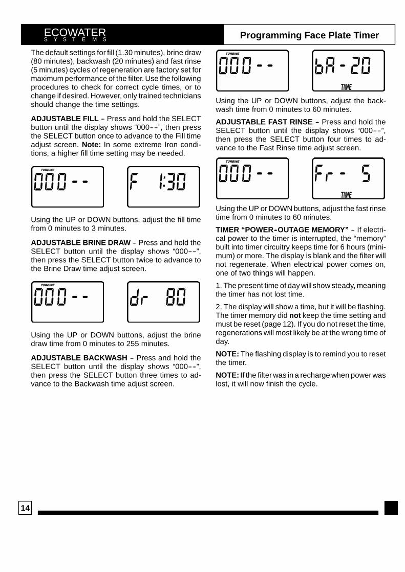
The default settings for fill (1.30 minutes), brine draw(80 minutes), backwash (20 minutes) and fast rinse(5 minutes) cycles of regeneration are factory set formaximum performance of the filter. Use the followingprocedures to check for correct cycle times, or tochange if desired. However, only trained techniciansshould change the time settings.
ADJUSTABLE FILL -- Press and hold the SELECTbutton until the display shows “000----”, then pressthe SELECT button once to advance to the Fill timeadjust screen. Note: In some extreme Iron condi-tions, a higher fill time setting may be needed.
Using the UP or DOWN buttons, adjust the fill timefrom 0 minutes to 3 minutes.
ADJUSTABLE BRINE DRAW -- Press and hold theSELECT button until the display shows “000----”,then press the SELECT button twice to advance tothe Brine Draw time adjust screen.
Using the UP or DOWN buttons, adjust the brinedraw time from 0 minutes to 255 minutes.
ADJUSTABLE BACKWASH -- Press and hold theSELECT button until the display shows “000----”,then press the SELECT button three times to ad-vance to the Backwash time adjust screen.
Using the UP or DOWN buttons, adjust the back-wash time from 0 minutes to 60 minutes.
ADJUSTABLE FAST RINSE -- Press and hold theSELECT button until the display shows “000----”,then press the SELECT button four times to ad-vance to the Fast Rinse time adjust screen.
Using the UP or DOWN buttons, adjust the fast rinsetime from 0 minutes to 60 minutes.
TIMER “POWER--OUTAGE MEMORY” -- If electri-cal power to the timer is interrupted, the “memory”built into timer circuitry keeps time for 6 hours (mini-mum) or more. The display is blank and the filter willnot regenerate. When electrical power comes on,one of two things will happen.
1. The present time of day will show steady, meaningthe timer has not lost time.
2. The display will show a time, but it will be flashing.The timer memory did not keep the time setting andmust be reset (page 12). If you do not reset the time,regenerations will most likely be at the wrong time ofday.
NOTE: The flashing display is to remind you to resetthe timer.
NOTE: If the filter was in a recharge when power waslost, it will now finish the cycle.

15
ECOWATERS Y S T E M S Filter Operation
During ‘‘service’’, the filter is providing filtered waterto the household. Iron is removed from the water bythe birm or manganese greensand mineral. Themineral oxidizes* the iron, and mechanically filters itfrom the water. At regular intervals, the mineralneeds cleaning to remove iron deposits, and to re-store oxygen content. This is done during regenera-tion with a potassium permanganate solution. Fill,solution draw, backwash, and fast rinse are stagesof the regeneration sequence.
* The mineral bed releases oxygen into the water, tochange the iron from a soluble to a solid form.
SERVICE (Figure 34, page 16): Unfiltered waterenters the filter valve inlet, passes through the valve,into the resin tank and mineral bed. Water is filteredas it passes through the bed, then exits through thebottom distributor. Flow continues up the internalstandpipe, into the valve, and out to the house pipes.
FILL (Figure 35, page 16): To begin a regeneration,or recharge, the timer energizes the circuit to thevalve motor. The motor rotates the switch activatingcam (valve cam) and valve inner discs. As the camrotates, the position switch lever is depressed by thecam. Upon reaching fill position, the lever is releasedoutward to open the circuit to the motor.
NOTE: The position switch is ‘‘normally open’’.
A secondary switch turns on the solenoid valve.Conditioned water is directed through the solenoidvalve and to the potassium permanganate feeder.A flow plug in the reducer fitting, at the nozzle as-sembly, maintains a 0.68 litres per minute fill flow
rate. From the fill flow plug, water passes into thefeeder tank. The fill water dissolves potassium per-manganate powder in the tank area. The float valveprevents tank overflows if other failure in the systemoccurs.
SOLUTION DRAW (Figure 36, page 17): The timerstarts the motor again to rotate the valve into solu-tion draw. Conditioned water is still directed to thenozzle, but filtered water flow to the venturi isstopped. Suction, created by the nozzle and venturi,draws potassium permanganate solution from thefeeder tank. Solution travels to the nozzle assembly,and into the filter tank. The solution rinses slowlythrough the mineral bed to restore oxygen used dur-ing service. Rinse water flows to the drain.
BACKWASH (Figure 37, page 17): The motordrives the valve to backwash position. The condi-tioned water shutoff valve closes, stopping flow tothe nozzle. In backwash, a fast upward flow of waterthrough the mineral bed flushes dirt, sediments, irondeposits, etc., from the bed and to the drain. The fastflow lifts and expands the mineral bed for maximumcleaning.
FAST RINSE (Figure 38, page 18): After backwash,valve rotation places the valve in fast rinse. The con-tinued fast flow of water changes direction to flowdownward through the mineral bed. Any remainingsolution, iron, etc., still at the bottom of the bed, areflushed up the standpipe and out the valve to thedrain. The mineral bed is packed by the fast flow, andprepared for service. The motor is energized a finaltime to return the valve to service position.

16
ECOWATERS Y S T E M S Filter Operation
FIGURE 34
SERVICE CYCLE
FIGURE 35
FILL CYCLE
To Valve Outlet(filtered water)
mineralbed
bottom distributor
mineraltank
top distributor
from Valve Inlet(unfiltered water)
mineralbed
To ValveOutlet
(filteredwater)
mineralbed
from Valve Inlet(unfiltered water)
position switch valve cam
rotor & disc
mineralbed
potassiumperm. powder
fill waterto feeder
FeederTank
motor
POSITIONSWITCH
POSITIONSWITCH

17
ECOWATERS Y S T E M S Filter Operation
FIGURE 36
SOLUTION DRAW CYCLE
drain
solution fromfeeder tank
bypass unfiltered waterto valve outlet
from Valve Inlet(unfiltered water)
solenoidvalve
fromsaddle valve
POSITIONSWITCH
FIGURE 37
BACKWASH CYCLE
drain
flow plugbypass unfiltered waterto valve outlet POSITION
SWITCH

18
ECOWATERS Y S T E M S Filter Operation
FIGURE 38
FAST RINSE CYCLEfiltered waterto valve outlet
drain
POSITIONSWITCH

19
ECOWATERS Y S T E M S Maintenance
HOW LONG DOES THE POTASSIUM PERMAN-GANATE LAST? Using 56.7 gram of powder eachregeneration (at 1 minute fill setting), 4.53 kg of po-tassium permanganate powder will last for about 80regenerations. Divide 80 by the number of regenera-tions needed each week. The answer is the approxi-mate number of weeks the potassium permanga-nate should last. The 2 minute fill setting uses 85gram of powder, and 3 minutes uses 113.4 gram.
It is important to add more potassium permanganatepowder before it’s entirely gone. If the filter goes toolong without a regeneration, the mineral will perma-nently lose it’s manganese coating. The completemineral bed would need replacement.
ADDING MORE POTASSIUM PERMANGANATE:
WARNING: Handle the container of powder withcare. Potassium permanganate stains deeply. Donot get it on your clothing or skin.
1. Remove the feeder tank cover.
2. Open the container of replacement powder andcarefully pour into the tank.
3. Level the powder.
4. Replace the tank cover.
IMPORTANT: Each time powder is added, alwaysdo the following maintenance, as needed. Depend-ing on several factors, this cleaning may be neededmore or less often.
1. Check and clean the nozzle assembly, page 20.
2. Check and clean all of the following as needed.
-- brine valve-- screen on the bottom of brinewell-- feeder tank drain hose-- feeder tank (flush with fresh, clean water)-- all tubing
NUMBER OF FULL WEEKS 10 LBS OFPOTASSIUM PERMANGANATE POWDER LASTS
no. of regenerationsh k
FILL CYCLE MINUTESgeach week 1 2 3
1 80 53 40
2 40 40 20
3 26 17 13
4 20 13 10
5 16 10 8
6 13 8 6
7 11 7 5
Note: The refill container has 4.53 kg of potassium permanganate pow-der.
cover
FIGURE 39
brinevalve
drainhose

20
ECOWATERS Y S T E M S Maintenance
CLEANING THE NOZZLE & VENTURI: The nozzleand venturi create the suction to transfer solutionfrom the feeder tank, into the mineral bed. If they be-come plugged or restricted with dirt, iron buildup,etc., they will not work. You should disassemble andclean the nozzle & venturi each time potassium per-manganate powder is added. Depending on thetype and/or amount of iron, you may need to cleanthem more often.
Important: Potassium permanganate solution mayoverflow from the feeder tank if the nozzle and ven-turi are not functioning correctly. Also refer to the im-portant note, page 19, and do step 2.
Clean the nozzle & venturi while the filter is in ‘‘ser-vice’’ (no water pressure at nozzle assembly) andnot while in regeneration. Be sure RECHARGENOW is not flashing in the time display.
1. Disconnect bottom tubing at the nozzle assembly(Figure 40) and turn the nozzle housing out of thenozzle & venturi housing.
2. Turn the nozzle out of the nozzle housing. If need-ed, remove the venturi with a long, needle-nose pli-ers to clean.
3. Clean parts in hot, soapy water. Use a small wireto clean holes in the nozzle and venturi. Use extremecare not to scratch, enlarge or misshape the holes,or surfaces around them. Flush parts in fresh, cleanwater.
4. Assemble all parts being sure to fully seat thenozzle and venturi in their respective locations. Donot forget the o-ring seal on the nozzle.
5. Replace the nozzle housing and reconnect thetubing. See page 10 for correct routing.
nozzle & venturihousing
venturi
nozzle
o-ring
nozzle housing
fill flowcontrol
FIGURE 40
ECOWATERS Y S T E M S Wiring Schematic
M24V
NC
NO
BACK OF TIMER
POSITIONSWITCH
SOLENOID VALVEPOSITION SWITCH
NC
NO
SOL
24VAC
TRANSFORMER

21
ECOWATERS Y S T E M S Service Information
TROUBLESHOOTING
ALWAYS MAKE THESE INITIAL CHECKS FIRST
1. Does the time display show the correct time ofday?
...If display is blank, check power source to the filter.
...If time is flashing, power was off for over two days.The filter resumes normal operation but rechargesoccur at the wrong time.
2. Plumbing bypass valve(s) must be in SERVICEposition (see Figure 31, page 11). Bleed screwclosed.(if present)
3. The inlet and outlet pipes must connect to the filterinlet and outlet respectively.
4. Is the transformer plugged into a “live” groundedwall outlet, and the power cable fastened securely?
5. The valve drain hose must be free of kinks andsharp bends.
If you do not find the problem after making the initialchecks, do the MANUAL ADVANCE DIAGNOS-TICS.
MANUAL INITIATEDELECTRONICS DIAGNOSTIC
1. To enter diagnostics, press and hold the SELECTkeypad until (000-- --) shows in the display.
The letter (P) and dash or dashes indicate positionswitch operation. The letter shows if the switch isclosed. A dash shows when the switch is open.
SWITCHDISPLAYS VALVE CYCLE STATUS
-- -- valve in service, fill, draw, back-wash or fast rinse position
-- P valve rotating from one position toanother
Use the RECHARGE keypad to manually advancethe valve into each cycle and check correct switchoperation.
While in this diagnostic screen, the following infor-mation is available and may be beneficial tor variousreasons. This information is retained by the comput-er from the first time electrical power is applied to theface plate.
...Press the UP keypad to display the number ofdays this face plate has had electrical power ap-plied.
...Press the DOWN keypad to display the number ofregenerations initiated by this face plate since themodel code number was entered.
2. Press the SELECT keypad and hold for 3 secondsuntil the model code appears in the display.
NOTE: For correct filter operation, the model codemust be HIF10.
To reset the code, press the UP or DOWN keypadsuntil the correct model code shows in the display.
3. Press the SELECT keypad to return the presenttime display. If the code was changed, make ALL thetimer settings, page 12 and 13.
NOTE: If the face plate is left in a diagnostic display (or a flashing display when setting times or daysto recharge), preset time automatically returns if a button is not pressed within 4 minutes.

22
Service InformationECOWATERS Y S T E M S
MANUAL ADVANCE DIAGNOSTIC
Use the following procedures to advance the filtervalve through the regeneration cycles to check op-eration.
Remove the top cover to observe cam and switchoperation during valve rotation.
DISPLAY MUST SHOW TIME AND DAY
1. Press and hold the RECHARGE keypad for 3 sec-onds until RECHARGE NOW flashes in the displayand the filter moves into the fill cycle.
...If the motor does not run, check the motor and allwiring connections.
Check for fill water flow to the brine tank. If waterdoes not enter the tank, look for an obstructednozzle and venturi, fill flow plug or brine tubing.
2. After verifying fill, press the RECHARGE keypadto move the valve into solution draw. A slow flow ofwater to the drain will begin. Verify solution drawfrom the brine tank by shinning the flashlight into thebrinewell and observing a noticeable drop in the liq-uid level.
If the unit does not draw brine, check for......dirty or defective nozzle and venturi...nozzle and venturi not seated on the gasket, orgasket defective
...restriction in valve drain, causing a back--pressure(bends, kinks, elevated too high, etc.),...obstruction in brine valve or brine tubing...inner valve failure (obstructed rotor disc, wavewasher defective, etc.)
3. Again press the RECHARGE keypad to move thevalve into backwash. Look for a fast flow of waterfrom the drain hose (see specifications, page 3).
...An obstructed flow indicates a plugged top distrib-utor, backwash flow plug, or drain hose.
NOTE: Be sure household water pressure (well sys-tem) is maintained at a minimum of 1.4 bar. Adjustthe pump switch upward, if needed.
4. Press the RECHARGE keypad to move the filterinto fast rinse. Again, look for a drain flow rate aboutthe same as backwash.
5. To return the filter to service, press the RE-CHARGE keypad once.
OTHER SERVICE
UNFILTERED WATER BYPASS (unfiltered water“bleeds” into filtered water supply.
1. Missing or defective o--ring(s) at resin tank tovalve connection (see pages 23 and 24).
2. Defective rotor disc, seal or wave washer (seepages 25 and 26).
WATER LEAKS FROM DRAIN HOSE (during ser-vice)
1. Defective rotor disc, seal, or wave washer.
2. Defective o--ring on disc shaft.
AUTOMATIC ELECTRONIC DIAGNOSTICS
The face plate has a self diagnostic function for theelectrical systems (except input power). The face
plate monitors the electronic components and cir-cuits for correct operation. If a malfunction occurs,an error code appears in the face plate display.
POSSIBLE DEFECT
CODE MOST LIKELY ---------------------------------------------------------------------------------------------- LEAST LIKELY
Err 01, Err 03& Err 04
wiring harness or connection to position switch / switch / valve defect causing high torque / motorinoperative
Err 05 faceplate
PROCEDURE FOR REMOVING ERROR CODE FROM FACEPLATE: 1. Unplug transformer-------- 2. Correct defect-------- 3.Plug in transformer-------- 4. Wait for 12 minutes. The error code will return if the defect was not corrected. Press and hold the RECHARGEkeypad for 3 seconds as an alternate way to clear an error code.

23
Repair PartsECOWATERS Y S T E M S
54
55
56
57
58
59
60
61
63
64
48
49
62
82
83
84
8586
87
88
8990
91
9293
94
See pages 25 & 26
68
69
70
71
72
73
74
7576
77
78
79
8081
FILTER ASSEMBLY
NOZZLE ASSEMBLY
POTASSIUM PERMANGANATEFEEDER ASSEMBLY
50
52
53
51
65
67
66
86
24
Repair PartsECOWATERS Y S T E M S
KEYNO.
PARTNO. DESCRIPTION
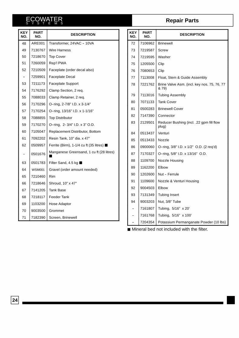
48 ARE001 Transformer, 24VAC -- 10VA
49 7130767 Wire Harness
50 7218670 Top Cover
51 7260059 Rep’l PWA
52 7210509 Faceplate (order decal also)
-- 7259901 Faceplate Decal
53 7211173 Faceplate Support
54 7176292 Clamp Section, 2 req.
55 7088033 Clamp Retainer, 2 req.
56 7170296 O--ring, 2-7/8” I.D. x 3-1/4”
57 7170254 O--ring, 13/16” I.D. x 1-1/16”
58 7088855 Top Distributor
59 7170270 O--ring, 2- 3/4” I.D. x 3” O.D.
60 7105047 Replacement Distributor, Bottom
61 7092202 Resin Tank, 10” dia. x 47”
62 0509957 Ferrite (Birm), 1-1/4 cu ft (35 litres) J
-- 0501676 Manganese Greensand, 1 cu ft (28 litres)J
63 0501783 Filter Sand, 4.5 kg J
64 WSM001 Gravel (order amount needed)
65 7210460 Rim
66 7218646 Shroud, 10” x 47”
67 7141205 Tank Base
68 7218117 Feeder Tank
69 1103200 Hose Adaptor
70 9003500 Grommet
71 7182390 Screen, Brinewell
KEYNO.
PARTNO. DESCRIPTION
72 7106962 Brinewell
73 7219587 Screw
74 7219595 Washer
75 1205500 Clip
76 7080653 Clip
77 7113008 Float, Stem & Guide Assembly
78 7221762 Brine Valve Asm. (incl. key nos. 75, 76, 77& 79)
79 7113016 Tubing Assembly
80 7071133 Tank Cover
81 0500283 Brinewell Cover
82 7147390 Connector
83 2129501 Reducer Bushing (incl. .22 gpm fill flowplug)
84 0513437 Venturi
85 0513433 Nozzle
86 0900060 O--ring, 3/8” I.D. x 1/2” O.D. (2 req’d)
87 7170327 O--ring, 5/8” I.D. x 13/16” O.D.
88 1109700 Nozzle Housing
89 1162200 Elbow
90 1202600 Nut -- Ferrule
91 1109600 Nozzle & Venturi Housing
92 9004503 Elbow
93 7131349 Tubing Insert
94 9003203 Nut, 3/8” Tube
-- 7161807 Tubing, 5/16” x 20’
-- 7161768 Tubing, 5/16” x 100’
-- 7204354 Potassium Permanganate Powder (10 lbs)
J Mineral bed not included with the filter.

25
Repair PartsECOWATERS Y S T E M S
2
1
3
4
5
6
7
8910
11
12
13
14
15
16
171819
20
21
22
24
26 25
32
34
36
37
38
39
22
cross--sectionview
seal
wear--strip
flow plugassembly
assembledview
28
27
29
23
41
40
3031
33
35
43
42

26
Repair PartsECOWATERS Y S T E M S
KEYNO.
PARTNO. DESCRIPTION
1 7224087 Screw, #8-32 x 1” (2)
2 7250622 Motor (incl. 2 ea. of Key No. 1)
3 7231393 Motor Plate
4 0900857 Screw, #6-20 x 3/8 (3)
5 7171250 Bearing
6 7219545 Cam and Gear
7 7169180 Clip (Drain)
8 7172793 Drain Hose Adaptor
9 7170288 O-ring, 15/16 x 1--3/16
10 7178202 Flow Plug, 7 gpm (greensand)
-- 7178189 Flow Plug, 5 gpm (birm)
11 -- O-ring, 5/8 x 13/16
12 -- O-ring, 1--1/8 x 1--1/2
13 7174313 Bearing, Wave Washer
14 7185500 Rotor & Disc
15 -- O-ring, 4--1/2 x 4--7/8
16 -- Rotor Seal
17 -- Seal
18 7171187 Plug (Drain Seal)
19 7129889 Spring
20 7089306 Clip (2 req.)
21 7077642 Copper Tube, 1” (2)
22 7170262 O--ring, 1--1/8 x 1--3/8 (4)
23 7078240 Support
24 7171145 Valve Body
25 -- Seal
KEYNO.
PARTNO. DESCRIPTION
26 7170319 O--ring, 1/4 x 3/8 (2)
27 1202600 Nut–Ferrule
28 7081201 Retainer
29 7128760 Adaptor, Nozzle Venturi
30 7220130 Wire Harness
31 7220148 Wire Harness
32 7175199 Wave Washer
33 7030713 Switch, Lever (solenoid)
34 7171161 Valve Cover
35 7142722 Solenoid
36 7172997 Screw, #10 x 2--5/8 (8 req.)
37 7145186 Switch, Button (position)
38 7140738 Screw, #4-24 x 3/4 (2 req.)
39 7214383 Bypass Valve (Includes following parts)
-- 7172882 Stem
-- 7173016 O--ring, 1.109 I.D. x 1.387 O.D. (4)
-- 7175238 C--ring
40 7207726 Ground Wire
41 7163427 Hose Clamp (2)
42 7147390 Connector, 5/16” Tube x 1/4” NPT
43 7120526 Elbow, 90_
7185487 Seal Kit (incl. key nos. 11, 12, 15, 16, 17and 25)