OWNER’S MANUAL - Excel Pool Products · Web viewOWNER’S MANUAL INSTALLATION, OPERATION, & PARTS...
18
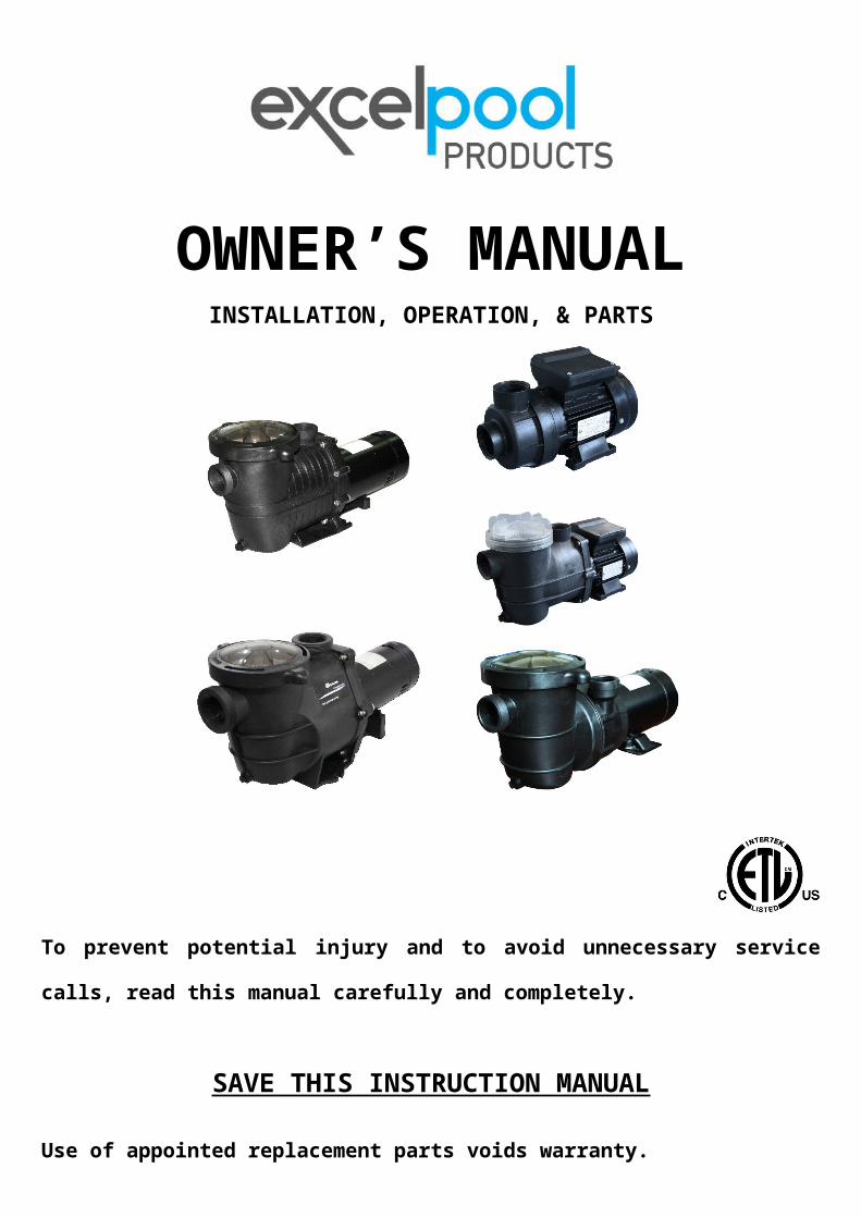
OWNER’S MANUAL INSTALLATION, OPERATION, & PARTS To prevent potential injury and to avoid unnecessary service calls, read this manual carefully and completely. SAVE THIS INSTRUCTION MANUAL Use of appointed replacement parts voids warranty.
Transcript of OWNER’S MANUAL - Excel Pool Products · Web viewOWNER’S MANUAL INSTALLATION, OPERATION, & PARTS...
OWNERrsquoS MANUALINSTALLATION OPERATION amp PARTS
To prevent potential injury and to avoid unnecessary service calls read this manual
carefully and completely
SAVE THIS INSTRUCTION MANUAL
Use of appointed replacement parts voids warranty
ATTENTION INSTALLER ndash THIS MANUAL CONTAINS IMPORTANT INFORMATION ABOUT THE INSTALLATION OPERATION AND SAFE USE OF THIS PUMP THAT MUST BE FURNISHED TO THE END USER OF THIS PRODUCT FAILURE TO READ AND FOLLOW ALL INSTRUCTIONS COULD RESULT IN SERIOUS INJURY
Symbol means
DANGER This symbol indicate that if failure to potential hazard it will cause severe personal injury or death or property
damage
WARNING This symbol indicate that if failure to potential hazard it could result in severe personal injury or death or
property damage
CAUTION This symbol indicate that if failure to potential hazard it will or could cause moderate personal injury or
property damage
CHAPTER One IMPORATANT SAFETY INSTUCTIONS READ AND FOLLOW ALL INSTRUCTION
WARNING Pay attention to children1 To reduce risk of injury do not permit children to use or climb on this product Closely supervise children at all times Components
such as the filtration system pumps and heaters must be positioned to prevent children from using them as a means of access to the pool
2 This pump is intended for use on permanently installed swimming pools and may also be used with hot tubs and spas if so marked NOT use with storable pools A permanently installed pool is constructed in or on the ground or in a building such that it cannot be readily disassembled for storage A storable pool is constructed so that it is capable of being readily disassembled for storage and reassembled to its original integrity
3 Though this product is designed for outdoor use it is strongly advised to protect the electrical components from the weather Select a well-drained area one that will not flood when it rains It requires free circulation of air for cooling Do not install in a damp or non-ventilated location
4 Pool and spa components have a finite life All components should be inspected frequently and replaced at least every five years or if found to be damaged broken cracked missing or not securely attached
WARNING Risk of Electric Shock 5 Hazardous voltage Can shock burn or cause death To reduce the risk of electric shock do NOT use an extension cord to connect
unit to electric supply Provide a properly located outlet It is required that licensed electricians do all electrical wiring All electrical wiring MUST be in conformance with applicable local and national codes and regulations Before working on pump or motor disconnect motor wiring
6 To reduce the risk of electric shock replace damaged cord immediately Do NOT bury cord Locate cord to prevent abuse from lawn mowers hedge trimmers and other equipment
7 Risk of Electric Shock Connect only to a branch circuit protected by a ground-fault circuit-interrupter (GFCI) Contact only to a electrician if you cannot verify that the receptacles is protected by a GFCI
8 Failure to bond pump to pool structure will increase risk for electrocution and could result in injury or death To reduce the risk of electric shock see installation instructions and consult a professional electrician on how to bond pumpAlso contact a licensed electrician for information on local electrical codes for bonding requirements
9 Use a solid copper conductor size 8 or larger Run a continuous wire from external bonding lug to reinforcing rod or mesh Connect a No 8 AWG (84 mm2) solid copper bonding wire to the pressure wire connector provided on the motor housing and to all metal parts of swimming pool spa or hot tub and to all electrical equipment metal piping (except gas piping) and conduit within 5 ft (15m) of inside walls of swimming pool spa or hot tub
IMPORTANT - Reference NEC codes for all wiring standards including but not limited to grounding bonding and other general wiring procedures NOTE - The National Electrical Code (NEC) permits use of a cord with a maximum 3 ft (1 m) length If your pump is equipped with a cord complying with the NEC the preceding four (4) hazards appl
10 Do not install within an outer enclosure or beneath the skirt of a hot tub or spa11 SAVE HESE INSTRUCTIONS12 These pumps are not poolside pumps
WARNING Suction Entrapment Hazard13 Suction in suction outlets andor suction outlet covers which are damaged broken cracked missing or unsecured cause severe
injury andor death due to the following entrapment hazardsHair Entrapment- Hair can become entangled in suction outlet coverLimb Entrapment- A limb inserted into an opening of a suction outlet sump or suction outlet cover that is damaged broken cracked
missing or not securely attached can result in a mechanical bind or swelling of the limbBody Suction Entrapment- A pressure applied to a large portion of the body or limbs can result in an entrapmentEvisceration Disembowelment- A negative pressure applied directly to the intestines through an unprotected suction outlet sump or
suction outlet cover which is damaged broken cracked missing or unsecured can result in eviscerationdisembowelment
Mechanical Entrapment- There is potential for jewelry swimsuits hair decorations fingers toes or knuckles to be caughtin an opening of a suction outlet cover resulting in mechanical entrapment
WARNING To Reduce the risk of Entrapment Hazards14 When outlets are small enough to be blocked by a person a minimum of two functioning suction outlets per pump must be
installed Suction outlets in the same plane (ie floor or wall) must be installed a minimum of three feet (3rsquo) [091 meter] apart as measured from near point to near point- Dual suction fittings shall be placed in such locations and distances to avoid ldquodual blockagerdquo by a user- Dual suction fittings shall not be located on seating areas or on the backrest for such seating areas- The maximum system flow rate shall not exceed the values shown in the ldquoPipe Sizing Chartrdquo found at this manual- Never use pool or spa if any suction outlet component is damaged broken cracked missing or not securely attached- Replace damaged broken cracked missing or not securely attached suction outlet components immediately- Installation of a vacuum release or vent system which relieves entrapping suction is recommended
WARNING Hazardous Pressure 15Pool and spa water circulation systems operate under hazardous pressure during start-up normal operation and after pump shut-
off Stand clear of circulation system equipment during pump start-up Failure to follow safety and operation instructions could result in violent separation of the pump housing and cover due to pressure in the system which could cause property damage severe personal injury or death Before servicing pool and spa water circulation system all system and pump controls must be in off position and filter manual air relief valve must be in open position Before starting system pump all system valves must be set in a position to allow system water to return back to the pool Do not change filter control valve position while system pump is running Before starting system pump fully open filter manual air relief valve Do not close filter manual air relief valve until a steady stream of water (not air or air and water) is discharged All suction and discharge valves MUST be OPEN when starting the circulation systemFailure to do so could result in severe personal injury andor property damage
WARNING Separation Hazard 16 Failure to follow safety and operation instructions could result in violent separation of pump components Strainer cover must be
properly secured to pump housing with strainer cover lock ring Before servicing pool and spa circulation system all system and pump controls must be in off position and filter manual air relief valve must be in open position Do not operate pool and spa circulation system if a system component is not assembled properly damaged or missing Do not operate pool and spa circulation system unless filter air relief valve body is in locked position in filter upper body All suction and discharge valves MUST be OPEN when starting the circulation systemFailure to do so could result in severe personal injury andor property damage
17 Never operate or test the circulation system at more than 40 PSIWARNING Fire and burn hazard
18 Motors operate at high temperatures and if they are not properly isolated from any flammable structures or foreign debris they can cause fires which may cause severe personal injury or death It is also necessary to allow the motor to cool for at least 20 minutes prior to maintenance to minimize the risk for burns
19 Il faut que le moteur soit contacteacute agrave la terre selon les regraveglements locaux et internationaux du code de machine eacutelectrique20 Il est interdit de laisser la pompe drsquoeau agrave fonctionner sans eau afin drsquoeacuteviter le choc eacutelectrique ou des autres risques21 Lrsquoinstallation de pompe drsquoeau doit ecirctre au moins 10 pieds de distance du paroi interne de piscine pour diminuer le risque de choc
eacutelectrique Nrsquoutiliser pas le cacircble eacutelectrique allongeacute22 Ce type de pompe drsquoeau nrsquoest qursquoutiliseacute dans la piscine du type drsquoinstallation permanente il ne peut pas ecirctre utiliseacute dans la piscine
du type gonflable ou mobile
CHAPTER Two Installation InstructionsWARNING This product should be installed and serviced only by a qualified professional1Pump Mounting
Install pump on a firm level base or pad to meet all local and national codes Fasten pump to base or pad with screws or bolts to further reduce vibration and stress on pipe or hose joints The base MUST be solid level rigid and vibration freePump mount must10487071048707Allow pump inlet height to be as close to water level as possible10487071048707Allow use of short direct suction pipe (to reduce friction losses)10487071048707Allow for gate valves in suction and discharge piping10487071048707Be protected from excess moisture and flooding10487071048707Allow adequate access for servicing pump and piping
Pipe Sizing Chart
NOTE - It is recommended that a minimum length of piping equivalent to 10 pipe diameters be used between the pump suction inlet and any plumbing fittings
WARNING Hazardous Pressure Pumps filters and other equipment components of a swimming pool filtration system operate under pressure Incorrectly installed andor improperly tested filtration equipment andor components may fail resulting in injury andor property damage
2 PlumbingUse Teflon tape to seal threaded connections on molded plastic components All plastic fittings must be new or thoroughly cleaned before use NOTE - Do NOT use Plumberrsquos Pipe Dope as it may cause cracking of the plastic components When applying Teflon tape to plastic threads wrap the entire threaded portion of the male fitting with one to two layers of tape Wind the tape clockwise as you face the open end of the fitting beginning at the end of the fitting The pump suction and outlet ports have molded-in thread stops Do NOT attempt to force hose connector fitting past this stop It is only necessary to tighten fittings enough to prevent leakage Tighten fitting by hand and then use a tool to engage fitting an additional 1 frac12 turns Use care when using Teflon tape as friction is reduced considerably do NOT over-tighten fitting or you may cause damage If leaks occur remove connector clean off old Teflon tape re-wrap with one to two additional layers of Teflon tape and re-install connector
3 FittingsFittings restrict flow For better efficiency use the fewest possible fittings (but at least two suction outlets) Avoid fittings that could cause an air trap Pool and spa fittings MUST conform to the International Association of Plumbing and Mechanical Officials (IAPMO) standards Use a non-entrapping suction fitting in pool (multiple drains) or double suction (skimmer and main drain)
CHAPTER Three Electrical 1 Ground and bond motor before connecting to electrical power supply Failure to ground and bond pump motor can cause serious or
fatal electrical shock hazard2 Do NOT ground to a gas supply line3 To avoid dangerous or fatal electrical shock turn OFF power to motor before working on electrical connections4 Ground Fault Circuit Interrupter (GFCI) tripping indicates electrical problem If GFCI trips and wonrsquot reset consult electrician to
inspect and repair electrical system
WARNING Fire Hazard 5 Match supply voltage to motor nameplate voltageInsure that the electrical supply available agrees with the motorrsquos voltage phase and cycle and that the wire size is adequate for the HP (KW) rating and distance from the power source
NOTE - All electrical wiring MUST be performed by a licensed electrician and MUST conform to local codes and NEC regulations Use copper conductors only6 VoltageVoltage at motor MUST NOT be more than 10 above or below motor name plate rated voltage or motor may overheat causing overload tripping and reduced component life If voltage is less than 90 or more than 110 of rated voltage when motor is running at full load consult Power Company
7 Grounding and BondingInstall ground bond and wire motor in accordance with local or national electrical code requirementsPermanently ground motor Use green ground terminal provided under motor canopy or access place use size and type wire required by code Connect motor ground terminal to electrical service ground Bond motor to pool structure Bonding will connect all metal parts within and around the pool with a continuous wire Bonding reduces the risk of a current passing between bonded metal objects which could potentially cause electrical shock if grounded or shortedReference NEC codes for all wiring standards including but not limited to grounding bonding and general wiring proceduresUse a solid copper conductor size 8 or larger Run wire from external bonding lug to reinforcing rod or mesh Connect a No 8 AWG (84 mm2) solid copper bonding wire to the pressure wire connector provided on the motor housing and to all metal parts of swimming pool spa or hot tub and to all electrical equipment metal piping (except gas piping) and conduit within 5 ft (15 m) of inside walls of swimming pool spa or hot tub
WARNING All wiring must be done by a licensed electrician8 WiringPump MUST be permanently connected to circuit If other lights or appliances are also on the same circuit be sure to add their amp loads before calculating wire and circuit breaker sizes Use the load circuit breaker as the Master On-Off switchInstall a Ground Fault Circuit Interrupter (GFCI) in circuit it will sense a short-circuit to ground and disconnect power before it
becomes dangerous to pool users For size of GFCI required and test procedures for GFCI see manufacturerrsquos instructions In case of a power outage check GFCI for tripping which will prevent normal pump operation Reset if necessaryNOTE - If you do not use conduit when wiring motor be sure to seal wire opening on end of motor to prevent dirt bugs etc from entering
CHAPTER Four Start-Up amp Operation Prior to Start-UpNotice If it is necessary to perform a pressure test prior to initial use to ensure pump is functioning properly then the following criteria should be maintained for this test1 Have a professional perform this test2 Ensure all pump and system components are sealed properly to prevent leaks3 Remove any trapped air in the system by fully opening filter manual air relief valve until a steady stream of water is discharged4 Allow no more than 40 psi (276 kPa) at a water temperature no higher than 100ordmF (381048707ordmC)5 Run pressure test for no longer than 24 hours Immediately inspect all parts to verify they are intact and functioning properly
Fill strainer housing with water to suction pipe level NEVER OPERATE THE PUMP WITHOUT WATER Water acts as a coolant and lubricant for the mechanical shaft seal
WARNING If pump is being pressure tested (40 PSI MAXIMUM) be sure pressure has been released using the filter manual air relief valve before removing strainer cover
CAUTION NEVER run pump dry Running pump dry may damage seals causing leakage flooding and voids warranty Fill strainer housing with water before starting motor
6 Do NOT add chemicals to poolspa system directly in front of pump suction Adding undiluted chemicals may damage pump and voids warranty
7 Before removing strainer cover1) STOP PUMP before proceeding2) CLOSE VALVES in suction and outlet pipes3) RELEASE ALL PRESSURE from pump and piping system using filter manual air relief valve See filter ownerrsquos manual for
more detail
Priming PumpCAUTION All suction and discharge valves MUST be OPEN as well as filter air relief valve (if available) on filter when
starting the circulating pump system Failure to do so could result in severe personal injury1) Release all pressure from filter pump and piping system See filter ownerrsquos manual2) If water source is higher than the pump pump will prime itself when suction and outlet valves are opened If water source is lower
than the pump unscrew and remove strainer cover fill strainer housing with water3) Clean and lubricate strainer cover O-ring each time it is removed Inspect O-ring and re-install on strainer cover4) Replace strainer cover on strainer housing turn clockwise to tighten coverNOTE - Tighten strainer cover by hand only (no wrenches)
CAUTION Turn on power and wait for pump to prime which may take up to five (5) minutes Priming time will depend on vertical length of suction lift and horizontal length of suction pipe If pump does NOT prime within five minutes stop motor and determine cause Be sure all suction and discharge valves are open when pump is running See Troubleshooting GuideWait five (5) seconds before re-starting pump Failure to do so may cause reverse rotation of motor and consequent serious pump damageClose filter manual air relief valve after pump is primed
CHAPTER Five Maintenance
10487071048707Clean strainer basket regularly Do NOT strike basket to clean Inspect strainer cover gasket regularly and replace as necessary10487071048707pumps have self-lubricating motor bearings and shaft seals No lubrication is necessary10487071048707Keep motor clean Insure air vents are free from obstruction to avoid damage Do NOT use water to hose off motor10487071048707Occasionally shaft seals must be replaced due to wear or damage Replace with seal assembly kit of SPLASH companySee ldquoShaft Seal Change Instructionsrdquo in this manual
CHAPTER Six StorageWinterization
WARNING Separation Hazard 1 Do not purge the system with compressed air Purging the system with compressed air can cause components to explode with risk
of severe injury or death to anyone nearby Use only a low pressure (below 5 PSI) high volume blower when air purging the pump filter or piping
2Allowing the pump to freeze will void the warranty3Use ONLY propylene glycol as antifreeze in your poolspa system Propylene glycol is nontoxic and will not damage plastic system
components other anti-freezes are highly toxic and may damage plastic components in the system4 Drain all water from pump and piping when expecting freezing temperatures or when storing pump for a long time (see instructions
below)5 Keep motor dry and covered during storage To avoid condensationcorrosion problems do NOT cover or wrap pump with plastic
film or bags
Storing Pump For WinterizationWARNING To avoid dangerous or fatal electrical shock hazard turn OFF power to motor before draining pump Failure to
disconnect power may result in serious personal injury or death1 Drain water level below all inlets to the pool2 Remove drain plugs from bottom of strainer body and remove strainer cover from strainer housing3 Disconnect pump from mounting pad wiring system (after power has been turned OFF) and piping system4 Once the pump is removed of water re-install the strainer cover and drain plugs Store pump in a dry area
Shaft Seal Change InstructionsIMPORTANT SAFETY INSTRUCTIONS PLEASE READ AND FOLLOW ALL INSTRUCTIONS
When servicing electrical equipment basic safety precautions should always be observed including the following Failure to followinstructions may result in injuryA To reduce risk of injury do not permit children to use this productB Disconnect all electrical power service to pump before beginning shaft seal replacementC Only qualified personnel should attempt rotary seal replacement Contact your local authorized Dealer or service center if you have
any questionsD The National Electrical Code requires either a three (3) foot maximum twist-lock cord set with a GFCI protected receptacle or hard
wire (conduit) connection for swimming pool pump installation Do not use extension cordsE Exercise extreme care in handling both the rotating and the stationary sections of the two-part replacement seal Foreign matter or
improper handling will easily scratch the graphite and ceramic sealing surfaces
CHAPTER Seven Troubleshooting A Motor Will NOT Start ndash Check ForMake sure the terminal board connections agree with the wiring diagram on motor data plate label Be sure motor is wired
for available field supply voltage (see pump operating label)1 Improper or loose wiring connections open switches or relays tripped circuit breakers GFCIrsquos or blown fuses
Solution Check all connections circuit breakers and fuses Reset tripped breakers or replace blown fuses2 Manually check rotation of motor shaft for free movement and lack of obstruction
Solution Refer to ldquoShaft Seal Change Instructionsrdquo in this manual3 If you have a timer be certain it is working properly Bypass it if necessary
B Motor Shuts OFF ndash Check For1 Low voltage at motor or power drop (frequently caused by undersized wiring or extension cord use)
Solution Contact qualified professional to check that the wiring gauge is heavy enoughNOTE - Your pump motor is equipped with an ldquoautomatic thermal overload protectorrdquo The motor will automatically shut off if
power supply drops before heat damage can build up causing windings to burn out The ldquothermal overload protectorrdquo will allow the motor to automatically restart once the motor has cooled It will continue to cut OnOff until the problem is corrected Be sure to correct cause of overheating
C Motor Hums But Does NOT Start ndash Check For1 Impeller jammed with debris
Solution Have a qualified repair professional open the pump and remove the debris
D Pump Wont Prime Check For1 Empty pumpstrainer housingSolution Make sure pumpstrainer housing is filled with water and cover o-ring is clean Ensure o-ring is properly seated in the
cover o-ring groove Ensure o-ring is lubricated and that strainer cover is locked firmly in positionLubricant will help to create a tighter seal
2 Loose connections on suction sideSolution Tighten pipeunion connections
NOTE - Any self-priming pump will not prime if there are suction air leaks Leaks will result in bubbles emanating from return fittings on pool wall
3 Leaking O-ring or packing glands on valvesSolution Tighten repair or replace valves
4 Strainer basket or skimmer basket loaded with debrisSolution Remove strainer housing cover or skimmer cover clean basket and refill strainer housing with water Tighten cover
5 Suction side cloggedSolution Contact a qualified repair professionalBlock off to determine if pump will develop a vacuum You should have 5rdquo-6rdquo of vacuum at the strainer cover (Only your pool dealer can confirm this with a vacuum gauge) You may be able to check by removing the skimmer basket and holding your hand over the bottom port with skimmer full and pump running If no suction is felt check for line blockagea If pump develops a vacuum check for blocked suction line or dirty strainer basket An air leak in the suction piping may be the
causeb If pump does not develop a vacuum and pump has sufficient ldquopriming waterrdquo
i Re-check strainer housing cover and all threaded connections for suction leaks Check if all system hose clamps are tightii Check voltage to ensure that the motor is rotating at full RPMrsquosiii Open housing cover and check for clogging or obstruction in suction Check impeller for debrisiv Remove and replace shaft seal only if it is leaking
E Low Flow ndash Generally Check For1 Clogged or restricted strainer or suction line
Solution Contact a qualified repair professional2 Undersized pool piping
Solution Correct piping size3 Plugged or restricted discharge line of filter valve partially closed (high gauge reading)
Solution Sand filters ndash backwash as per manufacturerrsquos instructions DE filters ndash backwash as per manufacturerrsquos instructions Cartridge filters ndash clean or replace cartridge
4 Air leak in suction (bubbles issuing from return fittings)Solution Re-tighten suction and discharge connections using Teflon tape Inspect other plumbing connections and tighten as
required5 Plugged restricted or damaged impeller
Solution Replace including new seal assembly
F Noisy Pump ndash Check For1 Air leak in suction piping cavitations caused by restricted or undersized suction line or leak at any joint low water level in pool
and unrestricted discharge return linesSolution Correct suction condition or throttle return lines if practical Holding hand over return fitting will sometimes prove this
point or putting in a smaller eyeball fitting2 Vibration due to improper mounting etcSolution Mount the pump on a level surface and secure the pump to the equipment pad3 Foreign matter in pump housing Loose stonesdebris hitting impeller could be causeSolution Clean the pump housing4 Motor bearings noisy from normal wear rust overheating or concentration of chemicals causing seal damage which will allow
chlorinated water to seep into bearings wiping out the grease causing bearing to whineSolution All seal leaks should be replaced at once
CHAPTER Eight Technical data Pump performance table
Pump model HP Volt HZ Amps Q (GPM) H (m) Remark7271272712TL 14 HP 115V60HZ 22 37 687271372713TL 14 HP 115V60HZ 22 33 87271472714TL 13 HP 115V60HZ 38 44 887271572715TL 13 HP 115V60HZ 38 40 107272872728TL 075HP SPL 115V60HZ 62 62 97272972729TL 10HP SPL 115V60HZ 88 75 1157273072730TL 15HP SPL 115V60HZ 95 83 1157274272742TL72742NC
075 HP 115V60HZ 88 73 14
7274372743TL72743NC
10 HP 115V60HZ 97 79 15
7274472744TL72744NC
15 HP 115V60HZ 15 88 20
72744H 15 HP 230V60HZ 75 88 207274772747TL72747NC
10 HP 115V60HZ 10 83 15
7274872748TL72748NC
15 HP 115V60HZ 15 97 20
72748H 15 HP 230V60HZ 75 97 20
CHAPTER Nine Pump structure amp parts
A Pump models72712 72712TL 7271472714TL
NO ERP number Part Name QTY
1 47251201080 Pump housing 1
2a 647271271000 Impeller for 72712 1
2b 647251271000 Impeller for 72714 1
3 5431069080 o-ring 1
4 5028013000 Seal assembly 1
5 47251202080 Pump cover 1
6a 5023010000 025HP motor for 72712 1
6b 5023011000 035HP motor for 72714 1
7 5224024000 Screw M5X20 4
B Pump models7271372715
NO ERP number Part Name QTY
1 47251503000 Cover 1
2 5431071080 o-ring 1
3 47251507001 basket 1
4 47251501080 Pump housing 1
5 5431070080 o-ring 1
6 47251504080 diffuser 1
7a 647271271000 Impeller for 72713 1
7b 647251271000 Impeller for 72715 1
8 5431037080 o-ring 1
9 5028013000 Seal assembly 1
10 47251502080 Pump cover 1
11 5224004000 Screw M6X25 6
12a 5023010000 025HP motor for 72713 1
12b 5023011000 035HP motor for 72715 1
13 5224024000 Screw M5X14 4
14 5231002000 Nut M6 6
15 5432002080 gasket 1
16 48860105080 Drain plug 1
C Pump moldels727287272972730
NO ERP number Part Name QTY
1 47252772 Cover 1
2 5431042080 o-ring 1
3 47252704080 Basket 1
4 47252705080 Clip 1
5 47252703080 Strainer housing 1
6 47252702080 Pump cover 1
7a 647272771000 Impeller for 72728 1
7b 647272971000 Impeller for 72729 1
7c 647252771000 Impeller for 72730 1
8 5028003000 Seal assembly 1
9 47252701080 Pump housing 1
10 5431040080 o-ring 1
11 5212016000 Screw ST55X25 8
12 5431029080 O-RING 1
13 5432002080 gasket 1
14 48860105080 Drain plug 1
15 47252708080 Motor mounting plate 1
16a 5023005000 075HP motor for 72728 1
16b 5023006000 10HP motor for 72729 1
16c 5023007000 15 HP motor for 72730 1
D Pump moldels727427274372744
NO ERP number Part Name QTY
1 47252772 Cover 1
2 5431042080 o-ring 1
3 47252704 Basket 1
4 47254201080 Pump housing 1
5 5431032080 o-ring 1
6 47254203080 Diffuser 1
7a 647274271000 Impeller for 72742 1
7b 647274371000 Impeller for 72743 1
7c 647254271000 Impeller for 72744 1
8 5431075080 o-ring 1
9 47254202080 Pump cover 1
10 5244005000 gasket M8 8
11 5221009000 Screw M8X40 8
12 5028003000 Seal assembly 1
13 5231004000 Nut M8 8
14 5432002080 gasket 1
15 48860105080 Drain plug 1
16 47254205080 Supporting foot 1
17 47254204080 Mounting foot 1
18a 5023019000 075HP motor for 72742 1
18b 5023020000 10HP motor for 72743 1
18c 5023021000 15HP motor for 72744 1
E Pump moldels7274772748
NO ERP number Part Name QTY1 47252772 Cover 12 5431042080 o-ring 13 47252704 Basket 14 47254701080 Pump housing 15 5431032080 o-ring 16 5212025000 Screw ST42X38 27 47254703080 Diffuser 18a 647274771000 Impeller for 72747 18b 647274871000 Impeller for 72748 19 5431074080 o-ring 110 47254702080 Pump cover 111 5244015000 Gasket M10 612 5225003000 Screw 38-161 12 UNC 613 5028014000 Seal assembly 114 47254705080 Supporting foot 115 47254704080 Mounting foot 116 5224003000 Screw M6X20 217 5244016000 Gasket M6 218 5231002000 Nut M6 219 5232001000 Nut 38-16 620 5432002080 Gasket 121 48860105080 Drain plug 122 5244015000 Gasket M10 423 5221008000 Screw M10X25 424a 5023022000 10HP motor for 72747 124b 5023023000 15HP motor for 72748 1
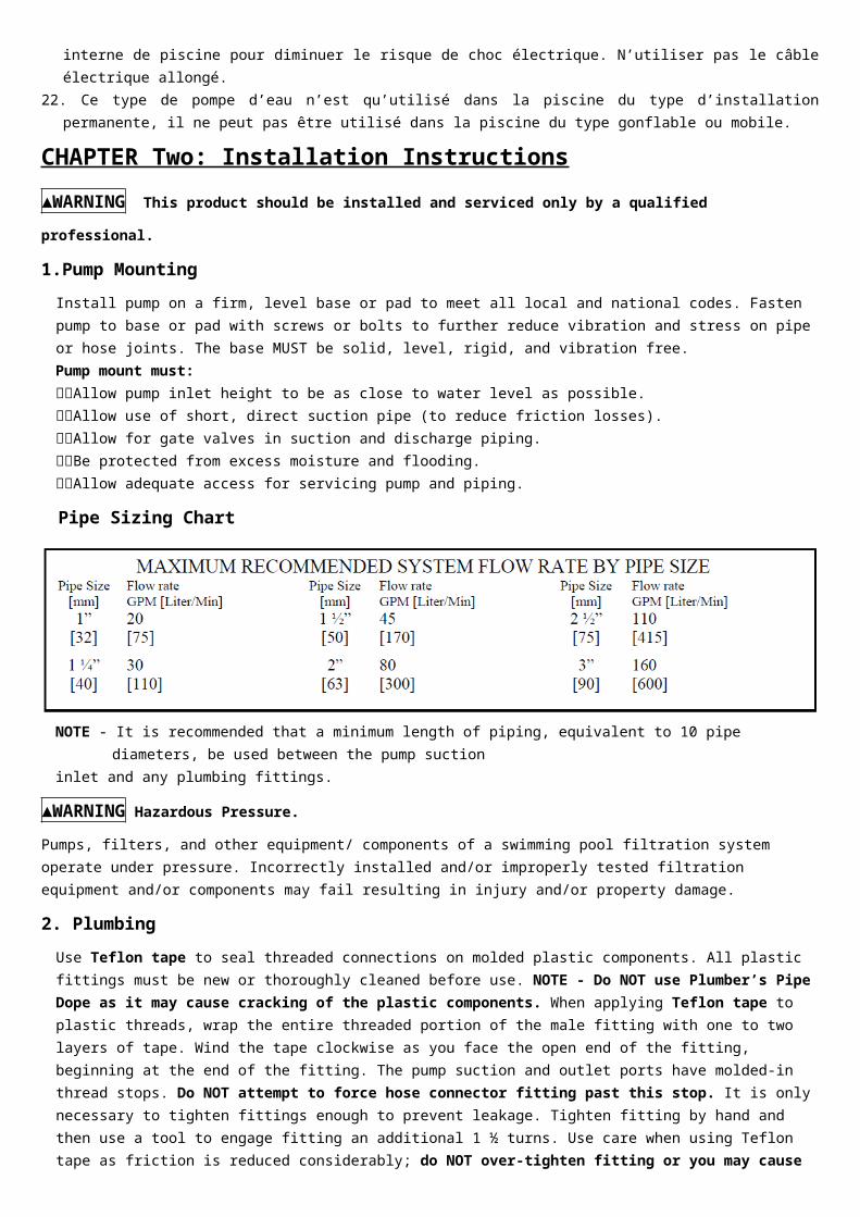
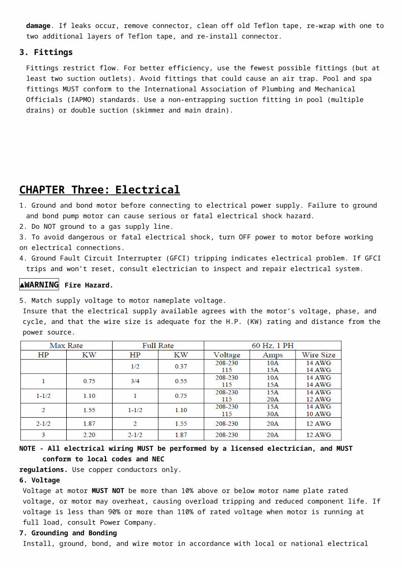
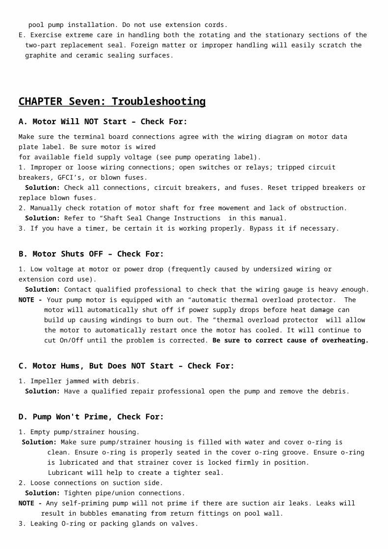
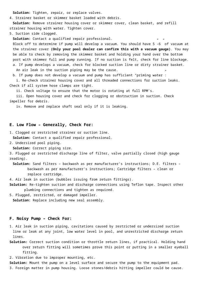
NO ERP number Part Name QTY
1 47251201080 Pump housing 1
2a 647271271000 Impeller for 72712 1
2b 647251271000 Impeller for 72714 1
3 5431069080 o-ring 1
4 5028013000 Seal assembly 1
5 47251202080 Pump cover 1
6a 5023010000 025HP motor for 72712 1
6b 5023011000 035HP motor for 72714 1
7 5224024000 Screw M5X20 4
B Pump models7271372715
NO ERP number Part Name QTY
1 47251503000 Cover 1
2 5431071080 o-ring 1
3 47251507001 basket 1
4 47251501080 Pump housing 1
5 5431070080 o-ring 1
6 47251504080 diffuser 1
7a 647271271000 Impeller for 72713 1
7b 647251271000 Impeller for 72715 1
8 5431037080 o-ring 1
9 5028013000 Seal assembly 1
10 47251502080 Pump cover 1
11 5224004000 Screw M6X25 6
12a 5023010000 025HP motor for 72713 1
12b 5023011000 035HP motor for 72715 1
13 5224024000 Screw M5X14 4
14 5231002000 Nut M6 6
15 5432002080 gasket 1
16 48860105080 Drain plug 1
C Pump moldels727287272972730
NO ERP number Part Name QTY
1 47252772 Cover 1
2 5431042080 o-ring 1
3 47252704080 Basket 1
4 47252705080 Clip 1
5 47252703080 Strainer housing 1
6 47252702080 Pump cover 1
7a 647272771000 Impeller for 72728 1
7b 647272971000 Impeller for 72729 1
7c 647252771000 Impeller for 72730 1
8 5028003000 Seal assembly 1
9 47252701080 Pump housing 1
10 5431040080 o-ring 1
11 5212016000 Screw ST55X25 8
12 5431029080 O-RING 1
13 5432002080 gasket 1
14 48860105080 Drain plug 1
15 47252708080 Motor mounting plate 1
16a 5023005000 075HP motor for 72728 1
16b 5023006000 10HP motor for 72729 1
16c 5023007000 15 HP motor for 72730 1
D Pump moldels727427274372744
NO ERP number Part Name QTY
1 47252772 Cover 1
2 5431042080 o-ring 1
3 47252704 Basket 1
4 47254201080 Pump housing 1
5 5431032080 o-ring 1
6 47254203080 Diffuser 1
7a 647274271000 Impeller for 72742 1
7b 647274371000 Impeller for 72743 1
7c 647254271000 Impeller for 72744 1
8 5431075080 o-ring 1
9 47254202080 Pump cover 1
10 5244005000 gasket M8 8
11 5221009000 Screw M8X40 8
12 5028003000 Seal assembly 1
13 5231004000 Nut M8 8
14 5432002080 gasket 1
15 48860105080 Drain plug 1
16 47254205080 Supporting foot 1
17 47254204080 Mounting foot 1
18a 5023019000 075HP motor for 72742 1
18b 5023020000 10HP motor for 72743 1
18c 5023021000 15HP motor for 72744 1
E Pump moldels7274772748
NO ERP number Part Name QTY1 47252772 Cover 12 5431042080 o-ring 13 47252704 Basket 14 47254701080 Pump housing 15 5431032080 o-ring 16 5212025000 Screw ST42X38 27 47254703080 Diffuser 18a 647274771000 Impeller for 72747 18b 647274871000 Impeller for 72748 19 5431074080 o-ring 110 47254702080 Pump cover 111 5244015000 Gasket M10 612 5225003000 Screw 38-161 12 UNC 613 5028014000 Seal assembly 114 47254705080 Supporting foot 115 47254704080 Mounting foot 116 5224003000 Screw M6X20 217 5244016000 Gasket M6 218 5231002000 Nut M6 219 5232001000 Nut 38-16 620 5432002080 Gasket 121 48860105080 Drain plug 122 5244015000 Gasket M10 423 5221008000 Screw M10X25 424a 5023022000 10HP motor for 72747 124b 5023023000 15HP motor for 72748 1
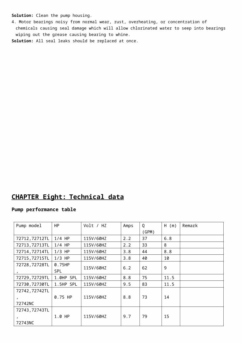
NO ERP number Part Name QTY
1 47252772 Cover 1
2 5431042080 o-ring 1
3 47252704080 Basket 1
4 47252705080 Clip 1
5 47252703080 Strainer housing 1
6 47252702080 Pump cover 1
7a 647272771000 Impeller for 72728 1
7b 647272971000 Impeller for 72729 1
7c 647252771000 Impeller for 72730 1
8 5028003000 Seal assembly 1
9 47252701080 Pump housing 1
10 5431040080 o-ring 1
11 5212016000 Screw ST55X25 8
12 5431029080 O-RING 1
13 5432002080 gasket 1
14 48860105080 Drain plug 1
15 47252708080 Motor mounting plate 1
16a 5023005000 075HP motor for 72728 1
16b 5023006000 10HP motor for 72729 1
16c 5023007000 15 HP motor for 72730 1
D Pump moldels727427274372744
NO ERP number Part Name QTY
1 47252772 Cover 1
2 5431042080 o-ring 1
3 47252704 Basket 1
4 47254201080 Pump housing 1
5 5431032080 o-ring 1
6 47254203080 Diffuser 1
7a 647274271000 Impeller for 72742 1
7b 647274371000 Impeller for 72743 1
7c 647254271000 Impeller for 72744 1
8 5431075080 o-ring 1
9 47254202080 Pump cover 1
10 5244005000 gasket M8 8
11 5221009000 Screw M8X40 8
12 5028003000 Seal assembly 1
13 5231004000 Nut M8 8
14 5432002080 gasket 1
15 48860105080 Drain plug 1
16 47254205080 Supporting foot 1
17 47254204080 Mounting foot 1
18a 5023019000 075HP motor for 72742 1
18b 5023020000 10HP motor for 72743 1
18c 5023021000 15HP motor for 72744 1
E Pump moldels7274772748
NO ERP number Part Name QTY1 47252772 Cover 12 5431042080 o-ring 13 47252704 Basket 14 47254701080 Pump housing 15 5431032080 o-ring 16 5212025000 Screw ST42X38 27 47254703080 Diffuser 18a 647274771000 Impeller for 72747 18b 647274871000 Impeller for 72748 19 5431074080 o-ring 110 47254702080 Pump cover 111 5244015000 Gasket M10 612 5225003000 Screw 38-161 12 UNC 613 5028014000 Seal assembly 114 47254705080 Supporting foot 115 47254704080 Mounting foot 116 5224003000 Screw M6X20 217 5244016000 Gasket M6 218 5231002000 Nut M6 219 5232001000 Nut 38-16 620 5432002080 Gasket 121 48860105080 Drain plug 122 5244015000 Gasket M10 423 5221008000 Screw M10X25 424a 5023022000 10HP motor for 72747 124b 5023023000 15HP motor for 72748 1
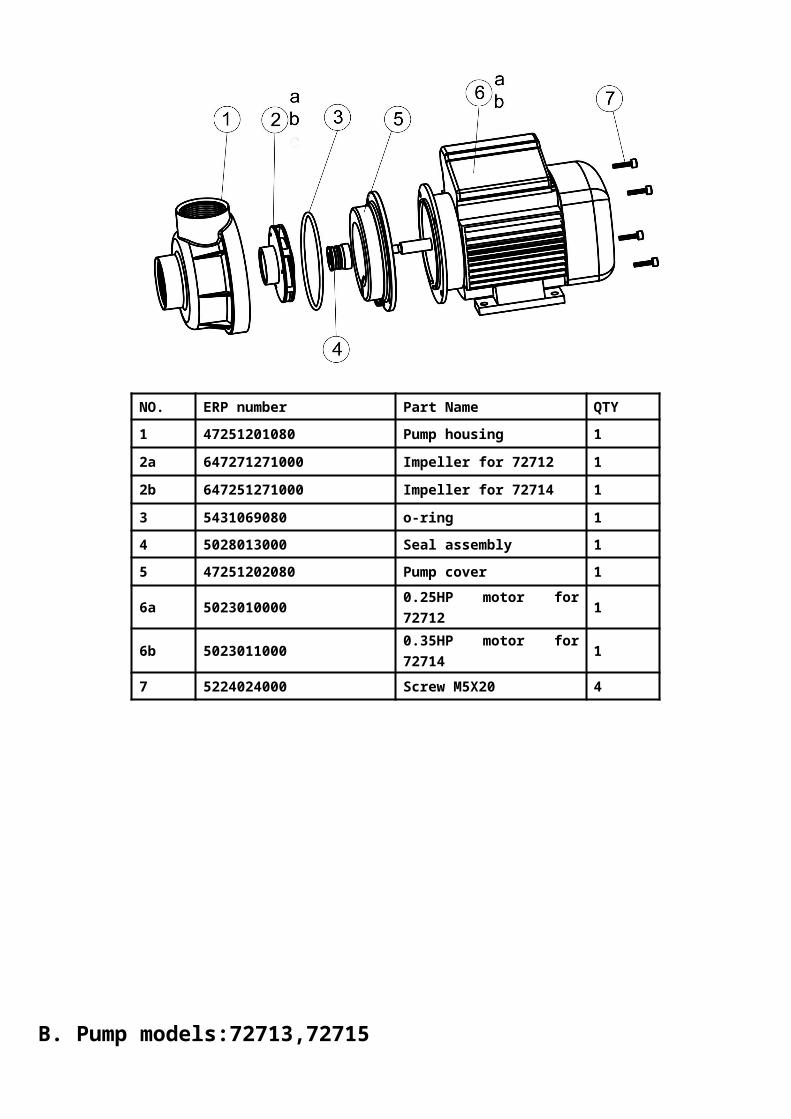
NO ERP number Part Name QTY
1 47252772 Cover 1
2 5431042080 o-ring 1
3 47252704 Basket 1
4 47254201080 Pump housing 1
5 5431032080 o-ring 1
6 47254203080 Diffuser 1
7a 647274271000 Impeller for 72742 1
7b 647274371000 Impeller for 72743 1
7c 647254271000 Impeller for 72744 1
8 5431075080 o-ring 1
9 47254202080 Pump cover 1
10 5244005000 gasket M8 8
11 5221009000 Screw M8X40 8
12 5028003000 Seal assembly 1
13 5231004000 Nut M8 8
14 5432002080 gasket 1
15 48860105080 Drain plug 1
16 47254205080 Supporting foot 1
17 47254204080 Mounting foot 1
18a 5023019000 075HP motor for 72742 1
18b 5023020000 10HP motor for 72743 1
18c 5023021000 15HP motor for 72744 1
E Pump moldels7274772748
NO ERP number Part Name QTY1 47252772 Cover 12 5431042080 o-ring 13 47252704 Basket 14 47254701080 Pump housing 15 5431032080 o-ring 16 5212025000 Screw ST42X38 27 47254703080 Diffuser 18a 647274771000 Impeller for 72747 18b 647274871000 Impeller for 72748 19 5431074080 o-ring 110 47254702080 Pump cover 111 5244015000 Gasket M10 612 5225003000 Screw 38-161 12 UNC 613 5028014000 Seal assembly 114 47254705080 Supporting foot 115 47254704080 Mounting foot 116 5224003000 Screw M6X20 217 5244016000 Gasket M6 218 5231002000 Nut M6 219 5232001000 Nut 38-16 620 5432002080 Gasket 121 48860105080 Drain plug 122 5244015000 Gasket M10 423 5221008000 Screw M10X25 424a 5023022000 10HP motor for 72747 124b 5023023000 15HP motor for 72748 1
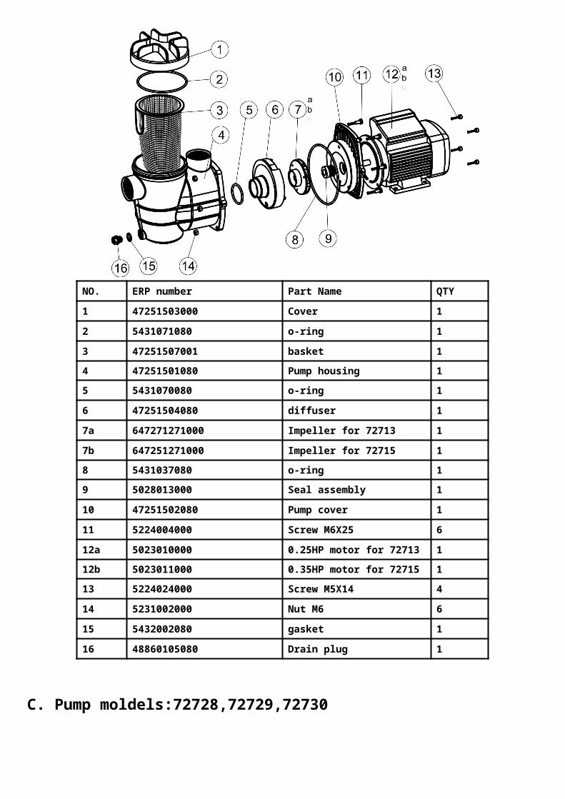
NO ERP number Part Name QTY1 47252772 Cover 12 5431042080 o-ring 13 47252704 Basket 14 47254701080 Pump housing 15 5431032080 o-ring 16 5212025000 Screw ST42X38 27 47254703080 Diffuser 18a 647274771000 Impeller for 72747 18b 647274871000 Impeller for 72748 19 5431074080 o-ring 110 47254702080 Pump cover 111 5244015000 Gasket M10 612 5225003000 Screw 38-161 12 UNC 613 5028014000 Seal assembly 114 47254705080 Supporting foot 115 47254704080 Mounting foot 116 5224003000 Screw M6X20 217 5244016000 Gasket M6 218 5231002000 Nut M6 219 5232001000 Nut 38-16 620 5432002080 Gasket 121 48860105080 Drain plug 122 5244015000 Gasket M10 423 5221008000 Screw M10X25 424a 5023022000 10HP motor for 72747 124b 5023023000 15HP motor for 72748 1