Owner’s Manual - design-mate.com · owner’s manual sy-a120 sy-a 240 sy-a 360 protect clip-20 db...
12
Owner’s Manual SY-A120 SY-A240 SY-A360 PROTECT CLIP -20 dB SIGNAL POWER POWER AMPLIFIER SY-A120 ON OFF PROTECT CLIP -20 dB SIGNAL POWER POWER AMPLIFIER SY-A240 ON OFF PROTECT CLIP -20 dB SIGNAL POWER POWER AMPLIFIER SY-A360 ON OFF
Transcript of Owner’s Manual - design-mate.com · owner’s manual sy-a120 sy-a 240 sy-a 360 protect clip-20 db...

Owner’s Manual
SY-A120
SY-A240
SY-A360
PROTECT
CLIP
-20 dB
SIGNAL
POWER
POWER AMPLIFIERSY-A120
ON
OFF
PROTECT
CLIP
-20 dB
SIGNAL
POWER
POWER AMPLIFIERSY-A240
ON
OFF
PROTECT
CLIP
-20 dB
SIGNAL
POWER
POWER AMPLIFIERSY-A360
ON
OFF
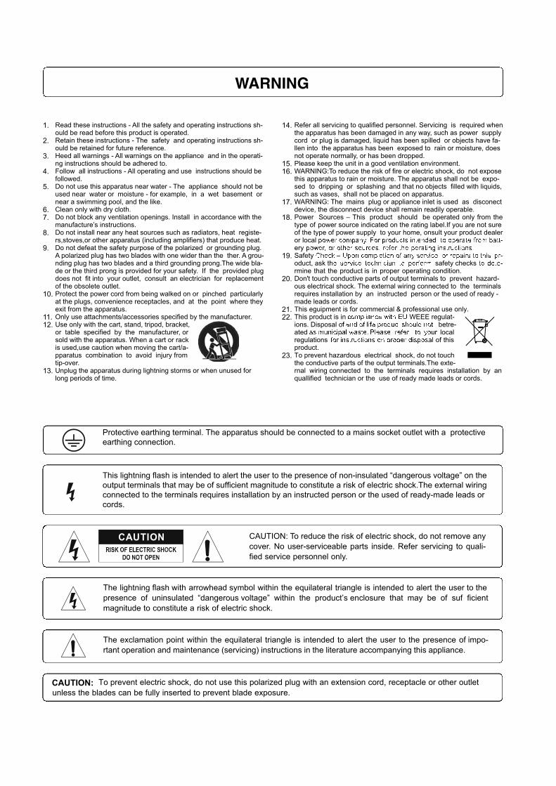
WARNING

1
SY-A120 / SY-A240 / SY-A360
Introductions ...................................................................................... 2
Features .............................................................................................. 3
Controls ............................................................................................... 4
Setups ................................................................................................. 5
Connections ...................................................................................... 6
Block diagrams ................................................................................ 8
Specifi cations ................................................................................... 9
Applications ...................................................................................... 10
Table of Contents
Table of Contents

2
SY-A120 / SY-A240 / SY-A360
Introduction
Welcome
Congratulation and thank you for the purchasing SYA series, a commercial power amplifi er.
These amplifi ers are designed to provide a big impact in sound reproduction and to produce the
best and highest quality audio at an affordable price. We wish you great enjoyment and satisfac-
tion when using your amplifi er, whether you are an installation, or reinforcement engineer.
Unpacking and Installation
Although it is neither complicated to install nor diffi cult to operate your amplifi er, a few minutes of
your time is required to read this manual for a properly wired installation and becoming familiar
with its features and how to use them. Please take a great care may be needed when moving
your set and are required if it ever becomes necessary to return your set for service. Never place
the unit near radiator, in front of heating vents, to direct sun light, In excessive humid or dusty
location to avoid damages and to guaranty a long reliable use.
Connect your unit with the system components according to the description on the following
pages.
PROTECT
CLIP
-20 dB
SIGNAL
POWER
POWER AMPLIFIERSY-A360
ON
OFF
SY-A120 / SY-A240 / SY-A360
Introductions

3
SY-A120 / SY-A240 / SY-A360
Features
Features
The SY-A120, SY-A240 and SY-A360 are comprehensive, qualifi ed power amplifi er solutions for
commercial and industrial applications. These low-cost units provide all necessary features in a
multifarious building-block format.
* One line input and one link output with XLR jacks.
* Low impedance(4Ω) and constant voltage(70V, 100V) output with EURO block terminal.
* 120watts(SY-A120), 240watts(SY-A240) and 360watts(SY-A360) rated power output.
* Advanced protection system includes current limiting, over current and thermal protection.
* 19-inches standard rack mountable type.
* Wide frequency range from 40Hz to 16kHz ± 3dB.
* Low distortion and low noise level.
* Designed for operation on either AC Mains or DC 24V evacuations.
* Adjustable input level from -12dB to 0dB.
* Built in 400Hz high-pass fi lter.
* Built in high temperature detection and auto muting function.
* Expendable by adding power amplifi er with LINK terminal.
* Compact size(2U) and lightweight.
* Ideal commercial and industrial use.

4
SY-A120 / SY-A240 / SY-A360
FRAME FLOAT
DC 24V INPUT SPEAKER OUTPUT
POWER AMPLIFIERSY-A360
-12 dB 0 dB
INPUTADJUST
LINKINPUT
GROUND
OFF ON
HPF400HzCOM100 V
(27.8 )38 V(4 )
70 V(13.6 )
DESIGNED AND ENGINEERED IN KOREA
WARNINGDO NOT EXPOSE
THIS EQUIPMENT TO RAIN OR MOISTURE
CAUTIONFOR CONTINUED
PROTECTION AGAINST RISK OF FIRE, REPLACE ONLY SAME TYPE FUSE
AVISRISQUE DE CHOC
ELECTRONIQUE NE PAS OUVRIR
ATTENTIONUTILISER UN FUSIBLE DE RECHANGE MEME
TYPE
Controls
Controls
1. Ventilation fan.2. Indicators ( Protection and Output level )3. Power switch with power indicator.
[ Figure 1.1 Front panel diagram ]
1. DC +24V input terminal.2.AC power input connector with fuse holder.
[ Figure 1.2 Rear panel diagram ]
PROTECT
CLIP
-20 dB
SIGNAL
POWER
POWER AMPLIFIERSY-A360
ON
OFF
Front Panels
Rear Panel
3. Speaker connection terminal (4-ohm, 70V, 100V and COM).4. Level adjustment (-12dB to 0dB).5. HPF(400Hz) on/off switch.6. Signal input and Link output connectors.7. Ground switch for provide against ground loop.8. Air fl ow.
VOLTAGE MODEL 115 / 120Vac 220 / 230 / 240 Vac
SY-A120 T4AL / 250V T3.15AL / 250VSY-A240 T8AL / 250V T4AL / 250VSY-A360 T12AL / 250V T6.3AH / 250V
1 2 3
1 2 3 4 5 6 7 8

5
SY-A120 / SY-A240 / SY-A360 Setups
Setups
CAUTION : Before you begin, make sure your amplifi er is disconnected from the power source, with the power switch in the “OFF” position.
Choose input wire and connectorsHPA recommends using pre-built or professionally wired balanced line. 22 to 24 gauge cables.Figure 2.1 shows connector pin assignments for wiring.
XLR Balanced Wiring Guide
For unbalanced use pin 1 and 3 have to beidge
Input output
1=ground/shield2=hot(+ve)3=cold(-ve)
21
312
3
[ Figure 2.1 Input wire and connectors ]
Choose output wire and connectorsFor the amplifi er output connectors, HPA recommends using pre-built or professionally wired,high-quality, and heavy gauge speaker wires. You may use EURO blocks for your output con-nectors. To prevent the possibility of short-circuits, wrap or otherwise insulate exposed loud-speaker cable connectors.Using the guidelines below, select the appropriate size wire based on the distance from amplifi er to speaker. The wire sizes apply to the 4-ohm tap.
NOTE : Custom wiring should only be performed by qualifi ed personnel. Class 2 wiring is re-quired.CAUTION : Never use shielded cable for output power wiring
Installation
Wiring Guide
Distance Wire SizeUp to 25 ft. 16 AWG26~40 ft. 14 AWG41~60 ft. 12AWG61~100 ft. 10AWG101ft~150 ft. 8AWG151~200 ft. 6AWG

6
SY-A120 / SY-A240 / SY-A360
OUTPUT : Maintain proper polarity on output connectors.
For output channel, connect the output EURO block terminals to the loudspeaker loads. Use terminals marked (4Ω) for a 4-ohm loudspeaker load, or use terminals marked 70V or 100V and COM for constant-voltage loudspeaker loads.
Connect the COM terminal to speaker negative(-) lead; connect one of the other terminals tospeaker positive(+) lead.
The impedance and output voltage are same as following Table 1.1
Connections
NOTE : Impedances indicated in the table1.1 represent the total speaker system impedances.
Speaker connection is shown in Figure 3.1
SPEAKER OUTPUT
COM100 V(41 )
31 V(4 )
70 V(21 )
SPEAKER OUTPUT
COM100 V(41 )
31 V(4 )
70 V(21 )
Matchingtransformer
8Ω 8Ω
4Ω
Connections
SYA-120 4Ω / 22V 41Ω / 70V 83Ω / 100VSYA-240 4Ω / 31V 21Ω / 70V 41Ω / 100VSYA-360 4Ω / 38V 13.6Ω / 70V 27.8Ω / 100V
[ Table 1.1 Output voltage and impedance ]
[ Figure 3.1 How to connect speakers ]

7
SY-A120 / SY-A240 / SY-A360
Connections
Connections
FRAME FLOAT
DC 24V INPUT SPEAKER OUTPUT
POWER AMPLIFIERSY-A360
-12 dB 0 dB
INPUTADJUST
LINKINPUT
GROUND
OFF ON
HPF400HzCOM100 V
(27.8 )38 V(4 )
70 V(13.6 )
DESIGNED AND ENGINEERED IN KOREA
WARNINGDO NOT EXPOSE
THIS EQUIPMENT TO RAIN OR MOISTURE
CAUTIONFOR CONTINUED
PROTECTION AGAINST RISK OF FIRE, REPLACE ONLY SAME TYPE FUSE
AVISRISQUE DE CHOC
ELECTRONIQUE NE PAS OUVRIR
ATTENTIONUTILISER UN FUSIBLE DE RECHANGE MEME
TYPE
CAUTION : Never use both the Low-Z(4 ohms) and Hi-Z(70V and 100V) terminals at the same time.
[ Figure 3.2 Wrong connection ]

8
SY-A120 / SY-A240 / SY-A360
Block diagrams
Block diagrams
B+

9
SY-A120 / SY-A240 / SY-A360 Specifi cations
Specifi cations
SY-A120 SY-A240 SY-A360
Electrical
Rated Output(at T.H.D 1.0%, 1kHz) 120Watt 240Watt 360Watt
Gain Control -12dB ~ 0dB
Input Sensitivity(at Balanced line) 1.0 ± 0.1Vrms / 10Kohm
High-pass Filter(at 400Hz) -3dB
Frequency Response +1.5 / -3 dB at 70Hz~18kHz
S/N Ratio Better than 90dB
T.H.D at 1/2 rated output, 1kHz Less than 1.0%
Output Voltage andImpedance
4Ω / 22V 4Ω / 31V 4Ω / 38V
41Ω / 70V 21Ω / 70V 13.6Ω / 70V
83Ω / 100V 41Ω / 100V 27.8Ω / 100V
Construction
Cooling FAN
Operating Temperature/Humidity 0°~40°C at 95% at non-condensing
Dimensions (Width/Height/Depth) 482 mm X 88 mm X 340 mm
Net Weight 11.65kg 13.87kg 15.16kg
Power Consumptions at 1/8 power 185W 361W 525W
Power Requirement AC100V~240V, 50/60Hz and/or DC24V
Necessary modifi cations are carried out without notice