Owner's Manual CRAFTSMAN - Lawn & Garden …s Manual CRAFTSMAN° l_l'lq 25.0 HP, 48" Mower Electric...
60
Owner's Manual CRAFTSMAN ° l_l'lq 25.0 HP, 48" Mower Electric Start Automatic Transmission Model No. 917.276020 This product has a mowemission engine which operates []_] from buimt Before start the differently previously engines. you engine, read and understand this Owner's Manual Read and follow aJJSafety Rules and Instructions before operating this equipment. For answers to your questions about this product, Call: 1_800°659-5917 Sears Craftsman Help Line 5 am - 5 pm, Men - Sat Sears, Roebuck and Co., Hoffman Estates, IL 60179 U.S.A. Visit our Craftsman website:www.sears.com/craftsman
Transcript of Owner's Manual CRAFTSMAN - Lawn & Garden …s Manual CRAFTSMAN° l_l'lq 25.0 HP, 48" Mower Electric...

Owner's Manual
CRAFTSMAN°l_l'lq
25.0 HP, 48" MowerElectric StartAutomatic Transmission
Model No.917.276020
This product has a mowemission engine which operates
[]_] from buimt Before start thedifferently previously engines. youengine, read and understand this Owner's Manual
Read and follow aJJSafetyRules and Instructions before
operating this equipment.
For answers to your questions
about this product, Call:
1_800°659-5917Sears Craftsman Help Line5 am - 5 pm, Men - Sat
Sears, Roebuck and Co., Hoffman Estates, IL 60179 U.S.A.Visit our Craftsman website:www.sears.com/craftsman

Warranty................................................2SafetyRules..........................................3ProductSpecifications...........................5Assembly/Pre-Operation.......................7Operation...............................................9MaintenanceSchedule........................16
Maintenance........................................16Service andAdjustments.....................20Storage................................................29Troubleshooting...................................30RepairParts.........................................34SearsService........................BackCover
LIMITEDWARRANTYON CRAFTSMANRIDINGEQUIPMENTFortwo (2)years from the date of purchase,if this CraftsmanRiding Equipmentismaintained,lubricatedand tuned upaccordingto the instructionsin the owner'smanual,Searswill repairor replacefree of chargeany parts that are foundto bedefectiveinmaterialor workmanshipaccordingto the guidelinesof coveragelisted below.Searswillalso providefree labor for theseapplicablewarrantedparts for the two full years.Duringthe first 30 daysof purchase,therewill be nochargesto servicethe productat yourhomefor issuescoveredby this warranty.(Seeexclusionsbelow). Foryourconve-nience, IN HOMEwarrantyservicewill still be availableafterthe first 30 daysof pur-chase, buta trip chargewill apply.Thischargewill bewaived if the Craftsmanproduct isdroppedoff at an authorizedSears location.For the nearestauthorizedSears location,pleasecall [email protected] warrantyapplies onlywhile this productis withinthe UnitedStates.
This Warrantydoes notcover:Expendableitemswhich becomeworn duringnormaluse, includingbut not limitedtoblades,spark plugs,air cleaners,belts,and oil filters.StandardMaintenanceServicing,oil changes, or tune-ups.Tire replacementor repaircausedby puncturesfrom outsideobjects,such as nails,thorns,stumps,or glass.Repairsnecessarybecauseof operatorabuse, includingbut not limitedto, damagecausedby towingobjectsbeyondthe capabilityof the ridingequipment,impactingobjectsthat bendthe frameor crankshaft,or over-speedingthe engine.Repairsnecessarybecauseof operatornegligence,includingbut not limitedto,elec-trical and mechanicaldamagecausedby improperstorage,failureto use the propergradeand amount of engine oil, failureto keepthe deckclear of flammabledebris,or failureto maintainthe equipmentaccordingto the instructionscontainedin theowner'smanual.Engine (fuel system)cleaningor repairscausedby fueldeterminedto becontami-nated or oxidized(stale). In general,fuel should beused within30 daysof its pur-chase date.Normaldeteriorationand wear of the exteriorfinishes,or productlabel replacement.Ridingequipmentusedfor commercialor rental purposes.
LIMITEDWARRANTYON BATTERYFor ninety(90) daysfrom date of purchase,if anybattery includedwith this ridingequip-ment provesdefectivein materialor workmanshipand our testingdeterminesthe batterywill not holda charge, Searswill replacethe batteryat nocharge. Duringthe first 30daysof purchase,therewill be nochargesto replacethe batteryat your HOME. Afterthe first 30 days, foryour convenience,IN-HOMEwarrantyservicewill still be avail-ablebut a trip chargewill apply. Thischarge will bewaived if the Craftsmanproduct isdroppedoff at an authorizedSears location.For the nearestauthorizedSears location,pleasecall 1-800-4-MY-HOME@.
This battery warrantyapplies onlywhile this productis within the UnitedStates.
This warrantygivesyou specificlegal rights,and you mayatso haveother rights,whichvary,from state to state.
Sears, Roebuck and Co.,Dept.817WA, Hoffman Estates, IL 60179
2

mlV]PORTANT: This cutting machine is capable of amputating hands and feet and throw-ing objects. Failure to observe the following safety instructions could result in seriousinjury or death.
In order to prevent ac-cidental starting when setting up, trans-porting, adjusting or making repairs,always disconnect spark plug wire andplace wire where it cannot contact sparkplug.
4_I, WARNmNG: Do not coast down a
hill in neutral, you may lose control of thetractor.
Tow only the attachmentsthat are recommended by and comply withspecifications of the manufacturer of yourtractor. Use common sense when towing.Operate only at the lowest possible speedwhen on a slope. Too heavy of a load,while on a slope, is dangerous. Tires canlose traction with the ground and causeyou to lose control of your tractor.
,_WARNmNG: Engine exhaust, some
of its constituents, and certain vehiclecomponents contain or emit chemicalsknown to the State of California to causecancer and birth defects or other reproduc-tive harm.
Battery posts, terminalsand related accessories contain lead and
lead compounds, chemicals known to theState of California to cause cancer and
birth defects or other reproductive harm.Wash hands after handling.
L GENERAL OPERATION
* Read, understand, and follow all instruc-tions in the manual and on the machine
before starting.Only allow responsible adults, who arefamiliar with the instructions, to operatethe machine.
, Clear the area of objects such as rocks,toys, wire, etc., which could be pickedup and thrown by the blade.Be sure the area is clear of other peoplebefore mowing. Stop machine if anyoneenters the area.
, Never carry passengers., Do not mow in reverse unless abso-
lutely necessary. Always look down andbehind before and while backing.
Be aware of the mower discharge direc-tion and do not point it at anyone. Donot operate the mower without eitherthe entire grass catcher or the guard inplace.Slow down before turning.Never leave a running machine unat-tended. Always turn off blades, setparking brake, stop engine, and removekeys before dismounting.Turn off blades when not mowing.Stop engine before removing grasscatcher or unclogging chute.Mow only in daylight or good artificiallight.Do not operate the machine while underthe influence of alcohol or drugs.Watch for traffic when operating near orcrossing roadways.Use extra care when loading or un-loading the machine into a trailer ortruck.
Data indicates that operators, age 60years and above, are involved in a largepercentage of riding mower-related in-juries. These operators should evaluatetheir ability to operate the riding mowersafely enough to protect themselves andothers from serious injury.Keep machine free of grass, leaves orother debris build-up which can touchhot exhaust / engine parts and burn. Donot allow the mower deck to plow leavesor other debris which can cause build-
up to occur. Clean any oil or fuelspillage before operating or storing themachine. Allow machine to cool before
storage.
H. SLOPE OPERATION
Slopes are a major factor related to loss-of-control and tipover accidents, which canresult in severe injury or death. All slopesrequire extra caution. If you cannot backup the slope or if you feel uneasy on it, donot mow it.
3

DO:
Mow up and down slopes, not across.Remove obstacles such as rocks, treelimbs, etc.Watch for holes, ruts, or bumps. Un-even terrain could overturn the machine.
Taft grass can hide obstacles.Use slow speed. Choose a low gearso that you will not have to stop or shiftwhile on the slope.Follow the manufacturer's recommend-ations for wheel weights or counter-weights to improve stability.Use extra care with grass catchers orother attachments. These can changethe stability of the machine.Keep all movement on the slopes slowand gradual Do not make suddenchanges in speed or direction.Avoid starting or stopping on a slope. Iftires lose traction, disengage the bladesand proceed slowly straight down theslope.
DO NOT:
o Do not turn on slopes unless neces-sary, and then, turn slowly and graduallydownhill, if possible.Do not mow near drop-offs, ditches,or embankments. The mower could
suddenly turn over if a wheel is overthe edge of a cliff or ditch, or if an edgecaves in.
Do not mow on wet grass. Reducedtraction could cause sliding.Do not try to stabilize the machine byputting your foot on the ground.Do not use grass catcher on steepslopes.
ill. CHILDREN
Tragic accidents can occur if the operatoris not alert to the presence of children.Children are often attracted to the ma-chine and the mowing activity. Never as-sume that children will remain where youlast saw them.
Keep children out of the mowing areaand under the watchful care of anotherresponsible adult.Be alert and turn machine off if childrenenter the area.
Before and when backing, look behindand down for small children.
Never carry children. They may fall offand be seriously injured or interfere withsafe machine operation.Never allow children to operate themachine.Use extra care when approaching blindcorners, shrubs, trees, or other objectsthat may obscure vision.
iV, SERVICE
Use extra care in handling gasoline andother fuels. They are flammable andvapors are explosive.-Use only an approved container.- Never remove gas cap or add fuelwith the engine running. Allowengine to cool before refueling. Donot smoke.
-Never refuel the machine indoors.- Never store the machine or fuel con-tainer inside where there is anopen flame, such as a water heater.
Never run a machine inside a closedarea.Keep nuts and bolts, especially bladeattachment bolts, tight and keep equip-ment in good condition.Never tamper with safety devices.Check their proper operation regularly.Keep machine free of grass, leaves, orother debris build-up. Clean oil or fuelspillage. Allow machine to cool beforestoring.Stop and inspect the equipment if youstrike an object. Repair, if necessary,before restarting.Never make adjustments or repairs withthe engine running.Grass catcher components are subjectto wear, damage, and deterioration,which could expose moving parts orallow objects to be thrown. Frequentlycheck components and replace withmanufacturer's recommended parts,when necessary.Mower blades are sharp and can cut.Wrap the blade(s) or wear gloves, anduse extra caution when servicing them.Check brake operation frequently. Ad-just and service as required.

Be sure the area is clear of other peoplebefore mowing.Stop machineif anyoneenters the area.Nevercarry passengersor childrenevenwith the bladesoff.Do not mow in reverseunlessabso-lutely necessary.Alwayslook downandbehind beforeand whilebacking.Nevercarry children.Theymayfall offand beseriously injuredor interferewithsafe machineoperation.Keepchildrenout of the mowingareaand underthe watchfulcare of anotherresponsibleadult.Be alert and turn machineoff if childrenenter the area.Beforeand when backing, look behindand downfor small children.Mowup and downslopes (15° Max), notacross.
Removeobstaclessuchas rocks,treelimbs,etc.Watchfor holes,ruts, or bumps.Uneventerrain couldoverturnthe machine.Tallgrasscan hide obstacles.Useslowspeed. Choosea low gearso that you will not haveto stop or shiftwhile on the slope.Avoidstartingor stoppingon a slope. Iftires losetraction,disengagethe bladesand proceedslowlystraightdowntheslope.If machinestops whilegoinguphill,disengageblades,shift into reverseandbackdownslowly.Do not turn on slopes unlessnecessary,andthen, turn slowlyand graduallydownhill,if possible.
PRODUCT SPECmFmCATmONS
Gasoline 5.0 GallonsCapacity UnleadedandType: RegularOilType SAE 10W30(API-SF-SJ): (above32°F)
SAE5W-30(below32°F)
Oil Capacity: W/Filter: 4.0 PintsW/O Filter: 3.5 Pints
SparkPlug: ChampionRC12YC(Gap: .030")
Ground Speed (MPH):Forward: 0 - 5.8Reverse: 0 - 2.1
Tire Pressure: Front: 14 PSIRear: 10PSI
ChargingSystem: 15AMPS @ 3600RPM
Battery: Amp/Hr: 35Min. CCA: 280Case size: U1R
Blade Bolt Torque: 45%5 Ft. Lbs.
CONGRATULATmONS on your purchaseof a new tractor. It has been designed,engineered and manufactured to giveyou the best possible dependability andperformance.Should you experience any problem youcannot easily remedy, please contact aSears or other qualified service center.We have competent, well-trained techni-cians and the proper tools to service orrepair this tractor.Please read and retain this manual. The
instructions will enable you to assembleand maintain your tractor properly. Alwaysobserve the "SAFETY RULES".
5

CUSTOMER RESPONSIBILITIES
* Read and observe the safety rules.* Follow a regular schedule in main-
taining, caring for and using your tractor.Follow the instructions under "Mainte-
nance" and "Storage" sections of thisowner's manual.
AWARNING: This tractor is equippedwith an internal combustion engine andshould not be used on or near any unim-proved forest-covered, brush-covered orgrass-covered land unless the engine'sexhaust system is equipped with a sparkarrester meeting applicable local or statelaws (if any). If a spark arrester is used, itshould be maintained in effective workingorder by the operator.In the state of California the above is re-
quired by law (Section 4442 of the Califor-nia Public Resources Code). Other statesmay have similar laws. Federal laws applyon federal lands. A spark arrester for themuffler is available through your nearestSears service center (See REPAIR PARTSsection of this manual).
REPAIR PROTECTmON
Congratulations on making a smart pur-chase. Your new Craftsman® product isdesigned and manufactured for years ofdependable operation. But like all prod-ucts, it may require repair from time totime. That's when having a Repair Protec-tion Agreement can save you money andaggravation.Purchase a Repair Protection Agreementnow and protect yourseff from unexpectedhassle and expense.
Here's what's included in the Agreement:* Expert service by our 12,000 profe-
sional repair specialists.Unlimited service and no charge forparts and labor on all covered repairs.Product replacement if your coveredproduct can't be fixed.Discount of 10% from regular price ofservice and service-related parts notcovered by the agreement; also, 10%off regular price of preventive mainte-nance check.
* Fast hemp by phone = phone supportfrom a Sears technician on productsrequiring in-home repair, plus conve-nient repair scheduling.
Once you purchase the Agreement, asimple phone call is all that it takes for youto schedule service. You can call anytimeday or night, or schedule a service ap-pointment online.Sears has over 12,000 professional repairspecialists, who have access to over 4.5million quality parts and accessories.That's the kind of professionalism you cancount on to help prolong the life of yournew purchase for years to come. Purchaseyour Repair Protection Agreement today!Some limitations and exclusions apply.For prices and additional informationcall 1-800=827-6655.
SEARS INSTALLATION SERVmCE
For Sears professional instaflation of homeappliances, garage door openers, waterheaters, and other major home items, inthe U.S.A. call 1-800=4=MY-HOME®
Video Cassette Keys_ Mower l I
< I Leveling l I
'/ Wrench I I
(1) Oil Drain Tube kJ Li
Slope Sheet
BubbleLevel

Yournew tractor hasbeen assembledat the factory. Reviewthe videocassette beforeyou begin.
When rightor left hand is mentionedinthis manual,it means,from your point ofview,whenyou are in the operatingposi-tion (seated behindthe steeringwheel).
TO REMOVE TRACTOR FROMCARTONUNPACKCARTON1. Cut alongdotted lineson all four pan-
elsof carton.Removeend panelsandlayside panelsflat.
2. Removepackingmaterials.3. Removeprotectivematerialsfrom trac-
tor hoodand grille.mMPORTANT:Checkfor and removeanystaples in skid that maypuncturetireswhere tractor is to roll off skid.HOW TO SET UP YOUR TRACTOR
CHECK BATTERY1. Lift hoodto raisedposition.NOTE:If this battery is put intoserviceafter monthandyear indicatedon label(label locatedbetweenterminals)chargebattery for minimumof one hourat 6-10amps.(See "BATTERY"in Maintenancesection of this manualfor charginginstruc-tions).
AdjustmentKnob
@@NOTE: You may now roll or drive yourtractor off the skid. Follow the appropriateinstruction below to remove the tractorfrom the skid.
TO ROLL TRACTOR OFF SKiD (SeeOperation section for mocation and
function of controms)1. Press lift lever plunger and raise
attachment lift lever to its highest po-sition.
2. Release parking brake by depressingbrake pedal.
3. Place freewheel control in transmission
disengaged position (See "To Trans-port" in the Operation section of thismanual).
4. Roll tractor forward off skid.
_:t__ s j/ _, LabeUeL
ADJUST SEAT
1. Raise seat and loosen adjustmentknobs.
2. Lower seat into operating position andsit in seat.
3. Slide seat until a comfortable positionis reached which allows you to pressclutch/brake pedal all the way down.
4. Get off seat without moving its ad-justed position.
5. Raise seat and tighten adjustmentknob securely.
TO DRIVE TRACTOR OFF SKmD (SeeOperation section for mocation and
_linction of controms)WARNmNG: Before starting, read, un-
derstand and follow all instructions in the
Operation section of this manual. Be suretractor is in a well-ventilated area. Be surethe area in front of tractor is clear of other
people and objects.1. Be sure all the above assembly steps
have been completed.2. Check engine oil level and fill fuel tank
with gasoline.3. Place freewheel control in "trans-
mission engaged" position (See "ToTransport" in the Operation section ofthis manual).
4. Sit on seat in operating position, de-press brake pedal and set the parkingbrake.
5. Press lift lever plunger and raiseattachment lift lever to its highest posi-tion.

6. Start the engine.Afterengine hasstarted, movethrottlecontrolto idleposition.
7. Releaseparkingbrake.8. Slowlymovethe motioncontrol lever
forwardand slowlydrive tractor offskid.
9. Apply braketo stop tractorand setparkingbrake.
10.Turn ignitionkeyto "STOP"position.Continuewith the instructionsthat follow.
CHECK TIRE PRESSUREThe tires on your tractorwere overinflatedat the factoryfor shippingpurposes. Cor-rect tire pressure is importantfor bestcutting performance.
Reducetire pressureto PSIshownin"PRODUCTSPECIFICATIONS"sectionof this manual.
CHECK DECK LEVELNESSFor bestcutting results,mowerhous-ing shouldbe properlyleveled. See "TOLEVELMOWERHOUSING"in the Serviceand Adjustmentssection of this manual.CHECK FOR PROPER POSITIONOF ALL BELTSSee the figuresthat areshownfor replac-ing motionand mowerbladedrive beltsin the Serviceand Adjustmentssectionof this manual. Verify that the beltsareroutedcorrectly.CHECK BRAKE SYSTEMAfter you learn how to operateyour trac-tor, check to see that the brakeis properlyadjusted. See "TOADJUSTBRAKE"inthe Serviceand Adjustmentssectionofthis manual.
,/'CHECKLISTBefore you operate your new tractor, wewish to assure that you receive the bestperformance and satisfaction from thisQuality Product.Please review the following checklist:,/All assembly instructions have been
completed.
,/No remaining loose parts in carton.
,/Battery is properly prepared andcharged. (Minimum 1 hour at 6 amps).
,/Seat is adjusted comfortably and tight-ened securely.
,/All tires are properly inflated. (For ship-ping purposes, the tires were overin-fiated at the factory).
,/Be sure mower deck is properly leveledside-to-sideifront-to-rear for best cuttingresults. (Tires must be properly inflatedfor leveling).
,/Check mower and drive belts. Be sure
they are routed properly around pulleysand inside atl belt keepers.
,/Check wiring. See that all connectionsare still secure and wires are properlyclamped.
,/Before driving tractor, be sure freewheelcontrol is in "transmission engaged"position (see "TO TRANSPORT" in theOperation section of this manual).
While learning how to use your tractor, payextra attention to the following importantitems:,/Engine oil is at proper level.
,/Fuel tank is filled with fresh, clean, regu-lar unleaded gasoline.
,/Become familiar with all controls, theirlocation and function. Operate thembefore you start the engine.
,/Be sure brake system is in safe operat-ing condition.
,/It is important to purge the transmissionbefore operating your tractor for the firsttime. Follow proper starting and trans-mission purging instructions (See "TOSTART ENGINE" and "PURGE TRANS-MISSION" in the Operation section ofthis manual).

Thesesymbols mayappearon your tractor or in literaturesuppliedwith the product.Learnand understandtheir meaning.
R N H I',,,IREVERSE NEUTRAL HIGH LOW CHOKE FAST
6 c!_#- GENGINE OFF LIGHTS ON ENGINE ON ENGINE START PARKING BRAKE
OVER TEMP FUEL OIL PRESSURE
LIGHT
ATTACHMENT ATTACHMENTCLUTCH ENGAGED CLUTCH DISENGAGED
FREE WHEEL
(Automatic Models only)
t
BATTERY REVERSE FORWARD
SLOW IGNITION
PARKING BRAKE PARKING BRAKE
LOCKED UNLOCKED
MOWER HEIGHT MOWER LIFT
DANGER, KEEP HANDSAND FEET AWAY
®@@@@KEEP AREA CLEAR SLOPE HAZARDS
(SEE SAFETY RULES SECTION)
Failure to follow instructions
could result in serious injury or
death. The safety alert symbol
is used to identify safety inform-ation about hazards which can
result in death, serious injuryand/or property damage.
&
DANGER indicates a hazard which, if not avoided,will result in death or serious injury.
WARNING indicates a hazard which, if not avoided,could result in death or serious injury.
CAUTION indicates a hazard which, if not avoided,might result in minor or moderate injury.
CAUTION when used without the alert symbol,indicates a situation that could result in damageto the tractor and/or engine.
HOT SURFACES indicates a hazard which,if not avoided, could result in death, serious injuryand/or property damage.
FIRE indicates a hazard which, if not avoided,could result in death, serious injury and/orproperty damage.
9

KNOW YOUR TRACTORREAD THINSOWNER'S MANUAL AND SAFETY RULES BEFORE OPERATmNG YOURTRACTOR
Compare the illustrations 'with your tractor to familiarize yourself with the locations ofvarious controls and adjustments. Save this manual for future reference.
Motion DriveBelt TensionHandle
ChokeControl
Throttle
Control
Brake Pedal
Ammeter ignitionLight SwitchPosition
AttachmentClutch
Lift
Plunger
AttachmentLift Lever
Parking BrakeLever
Height
Knob
Motion ControlLever
Free WheelControl
Our tractors conform to the safety standards of theAmerican National Standards Institute.
ATTACHMENT CLUTCH SWmTCH = Used
to engage the mower blades, or other at-tachments mounted to your tractor.UGHT SWmTCH POSmTmON - Turns theheadlights on and off.THROTTLE CONTROL - Used to control
engine speed.BRAKE PEDAL - Used for braking thetractor and starting the engine.CHOKE CONTROL - Used when startinga cold engine.HEmGHT ADJUSTMENT KNOB - Used to
adjust the mower cutting height.mGNITmON SWmTCH - Used for starting andstopping the engine.ATTACHMENT LIFT LEVER - Used to raiseand lower the mower deck or other attachmentsmounted to your tractor.
UFT LEVER PLUNGER - Used to release
attachment lift lever when changing itsposition.AMMETER - Indicates charging (+) ordischarging (-) of battery.PARKmNG BRAKE LEVER - Locks brakepedal into the brake position.MOTmON CONTROL LEVER - Selects the
speed and direction of tractor.FREEWHEEL CONTROL - Disengagestransmission for pushing or slowly towingthe tractor with the engine off.MOTmON DRmVE BELT TENSmON HAN-
DLE - Used when changing motion drivebelt and, if necessary, starting engineunder extremely cold conditions.
10

SAFETYGLASSES
The operation of any tractor can result in foreign objects thrown intothe eyes, which can result in severe eye damage. Always wear safetyglasses or eye shields while operating your tractor or performing anyadjustments or repairs. We recommend standard safety glasses or awide vision safety mask worn over spectacles.
HOW TO USE YOUR TRACTORTO SET PARKmNG BRAKE
Your tractor is equipped with an operatorpresence sensing switch. When engineis running, any attempt by the operatorto leave the seat without first setting theparking brake will shut off the engine.1. Depress brake pedal all the way down
and hold.
2. Pull parking brake lever up and releasepressure from brake pedal. Pedalshould remain in brake position. Makesure parking brake will hold tractorsecu re.
Choke Pushqn to Attachment CUutchControU ngage" Switch Pull Out to
"Engage"
ThrottleControl,
PedalMotionControl=ever
ustment Parking BrakeKnob "Disengaged" "Engaged"
Brake PedaU Position Position"Drive" Position
STOPPmNG
MOWER BLADES =
To stop mower blades, push attachmentclutch switch in to disengaged position.
GROUND DRIVE =
To stop ground drive, depress brakepedal all the way down.
mMPORTANT: The motion control leverreturns to neutral (N) position when thebrake pedal is fully depressed.
ENGINE =
Move throttle control between half and
full speed (fast) position.NOTE: Failure to move throttle controlbetween half and full speed (fast) posi-tion, before stopping, may cause engineto "backfire".
Turn ignition key to "STOP" position andremove key. Always remove key whenleaving tractor to prevent unauthorizeduse.
Never use choke to stop engine.IMPORTANT: Leaving the ignition switchin any position other than "STOP" willcause the battery to discharge and godead.NOTE: Under certain conditions when
tractor is standing idle with the enginerunning, hot engine exhaust gases maycause "browning" of grass. To eliminatethis possibility, always stop engine whenstopping tractor on grass areas.
I_kCAUTION: Always stop tractor com-
pletely, as described above, before leavingthe operator's position.
TO USE THROTTLE CONTROL
Always operate engine at full throttle.Operating engine at less than fullthrottle reduces the battery chargingrate.Full throttle offers the best mower per-formance.
TO USE CHOKE CONTROL
Use choke control whenever you are start-ing a cold engine. Do not use to start awarm engine.
To engage choke control, pull knob out.Slowly push knob in to disengage.
TO MOVE FORWARD AND
BACKWARD
CAUTION: Do not attempt to operate mo-tion control lever when the parking brakeis set or when the brake pedal is de-pressed. Doing so may result in misadjust-merit to the drive control system.The direction and speed of movement iscontrolled by the motion control lever.1. Start tractor with motion control lever in
neutral (N) position.2. Release parking brake.3. Slowly move motion control lever to
desired position.
11

TO ADJUST MOWER CUTTmNG HEmGHT
The cutting height is controlled by turn-ing the height adjustment knob in desireddirection.
,, Turn knob clockwise (f_) to raise cut-ting height.
,, Turn knob counterclockwise (_) tolower cutting height.
The cutting height range is approximately1-1/2" to 4-1/2". The heights are mea-sured from the ground to the blade tip withthe engine not running.These heights are approximate and mayvary depending upon soil conditions,height of grass and types of grass beingmowed.
,, The average lawn should be cut toapproximately 2-1/2 inches during thecool season and to over 3 inches duringhot months. For healthier and betterlooking lawns, mow often and aftermoderate growth.
,, For best cutting performance, grass over6 inches in height should be mowedtwice. Make the first cut relatively high;the second to desired height.
TO ADJUST GAUGE WHEELS
Gauge wheels are properly adjustedwhen they are slightly off the ground whenmower is at the desired cutting height inoperating position. Gauge wheels thenkeep the deck in proper position to helpprevent scalping in most terrain conditions.NOTE: Be sure tractor is on a flat levelsurface.1. Lower mower and adjust mower to
desired cutting height.2. Remove retainer spring and clevis pin
which secure each gauge wheel bar.3. Lower gauge wheels to ground. Raise
gauge wheels slightly to align holesin bracket and gauge wheel bar andinsert clevis pin. Gauge wheels shouldbe slightly off the ground.
4. Replace retainer spring into clevis pin.5. Be sure all gauge wheels are in the
same setting.mMPORTANT: Be sure to readjust gaugewheels if you change the cutting heightof the mower deck.
RetainerSpring
ClevisPin
TO OPERATE MOWER
Your tractor is equipped with an operatorpresence sensing switch. Any attemptby the operator to leave the seat with theengine running and the attachment clutchengaged will shut off the engine.1. Select desired height of cut.2. Lower mower with attachment lift con-
trol.
3. Start mower blades by engaging at-tachment clutch control.
TO STOP MOWER BLADES -
disengage attachment clutch control._,CAUTmON: Do not operate the mowerwithout either the entire grass catcher,on mowers so equipped, or the deflectorshield in place.
Attachment ClutchSwitch Pull Out to"Engage"
Attachemnt LiftLever High Position
Push!in to"Disengage"
DeflectorShield
TO OPERATE ON HmLLS
_,WARNmNG: Do not drive up or downhills with slopes greater than 15 ° and donot drive across any slope. Use the slopeguide provided at the back of this manual.,, Choose the slowest speed before start-
ing up or down hills.
12

Avoid stopping or changing speed onhills.
If stopping is absolutely necessary, pushbrake pedal quickly to brake positionand engage parking brake.
mMPORTANT: The motion control lever
returns to neutral (N) position when thebrake pedal is depressed.* To restart movement, slowly release
parking brake and brake pedal.* Slowly move motion control lever to
slowest setting.Make all turns slowly.
TO TRANSPORT
When pushing or towing your tractor, besure to disengage transmission by placingfreewheel control in freewheeling position.Freewheel control is located at the reardrawbar of tractor.
1. Raise attachment lift to highest positionwith attachment lift control.
2. Pull freewheel control out and into theslot and release so it is held in thedisengaged position.
* Do not push or tow tractor at more thantwo (2) MPH.
* To re-engage transmission, reverseabove procedure.
Transmission Engaged
Transmission Disengaged
NOTE: To protect hood from damagewhen transporting your tractor on a truckor a trailer, be sure hood is closed andsecured to tractor. Use an appropriatemeans of tying hood to tractor (rope, cord,etc.).
TOWmNG CARTS AND OTHER ATTACH=MENTS
Tow only the attachments that are recom-mended by and comply with specificationsof the manufacturer of your tractor. Usecommon sense when towing. Too heawof a load, while on a slope, is dangerous.Tires can lose traction with the ground andcause you to lose control of your tractor.
BEFORE STARTmNG THE ENGmNE
CHECK ENGmNE OraL LEVEL
The engine in your tractor has beenshipped, from the factory, already filledwith summer weight oil.1. Check engine oil with tractor on level
ground.2. Unthread and remove oil fill cap/
dipstick; wipe oil off. Reinsert thedipstick into the tube and rest oil fillcap on the tube. Do not thread the caponto the tube. Remove and read oil
level. If necessary, add oil until "FULE'mark on dipstick is reached. Do notoverfill.
* For cold weather operation you shouldchange oil for easier starting (See theoil viscosity chart in the Maintenancesection of this manual).To change engine oil, see the Mainte-nance section in this manual.
ADD GASOUNE
* Fill fuel tank to bottom of filler neck. Donot overfill. Use fresh, clean, regularunleaded gasoline with a minimum of87 octane. (Use of leaded gasoline willincrease carbon and lead oxide depositsand reduce valve life). Do not mix oilwith gasoline. Purchase fuel in quan-tities that can be used within 30 days toassure fuel freshness.
_CAUTmON: Wipe off any spilled oil orfuel. Do not store, spill or use gasolinenear an open flame.mMPORTANT: When operating in temper-atures below32°F(0°C), use fresh, cleanwinter grade gasoline to help insure goodcold weather starting.CAUTION: Alcohol blended fuels (calledgasohol or using ethanol or methanol) canattract moisture which leads to separa-tion and formation of acids during storage.Acidic gas can damage the fuel systemof an engine while in storage. To avoidengine problems, the fuel system shouldbe emptied before storage of 30 daysor longer. Drain the gas tank, start theengine and let it run until the fuel linesand carburetor are empty. Use fresh fuelnext season. See Storage Instructions foradditional information. Never use engineor carburetor cleaner products in the fueltank or permanent damage may occur.
13

TO START ENGINE
When starting the engine for the first timeor if the engine has run out of fuel, it willtake extra cranking time to move fuel fromthe tank to the engine.1. Be sure freewheel control is in the
transmission engaged position.2. Sit on seat in operating position,
depress brake pedal and set parkingbrake.
3. Move attachment clutch to disengagedposition.
4. Move throttle control to fast position5. Pull choke control out for a cold engine
start attempt. For a warm engine startattempt the choke control may not beneeded.
NOTE: Before starting, read the warm andcold starting procedures below.6. Insert key into ignition and turn key
clockwise to start position and releasekey as soon as engine starts. Donot run starter continuously for morethan fifteen seconds per minute. If theengine does not start after severalattempts, push choke control in, waita few minutes and try again. If enginestill does not start, pull the choke con-trol out and retry.
WARM WEATHER STARTING (50 ° F andabove)
7. When engine starts, slowly push chokecontrol in until the engine begins torun smoothly. If the engine starts torun roughly, pull the choke control outslightly for a few seconds and thencontinue to push the control in slowly.
The attachments and ground drive cannow be used. If the engine does notaccept the load, restart the engine andallow it to warm up for one minute usingthe choke as described above.
COLD WEATHER STARTING (50 ° F andbelow)
7. When engine starts, slowly push chokecontrol in until the engine begins to runsmoothly. Continue to push the chokecontrol in small steps allowing the en-gine to accept small changes in speedand load, until the choke control is fullyin. If the engine starts to run roughly,pull the choke control out slightly for afew seconds and then continue to pushthe control in slowly. This may requirean engine warm-up period from severalseconds to several minutes, dependingon the temperature.
NOTE: In extreme cold conditions, ifengine will not start you may need to dis-engage the motion drive belt as follows:1. Be sure parking brake is engaged.2. Remove retainer spring from the drive
belt tension handle to relieve belt ten-sion.
3. Start engine and allow it to warm up forthree (3) minutes.
4. Shut-off engine and engage parkingbrake.
5. Engage drive belt tension handle andreplace the retainer spring.
AUTOMATIC TRANSMISSION WARM UP
Before driving the unit in cold weather,the transmission should be warmed up asfollows:
1. Be sure the tractor is on level ground.2. Place the motion control lever in
neutral. Release the parking brake andlet the brake slowly return to operatingposition.
3. Allow one minute for transmission to
warm up. This can be done during theengine warm up period.
The attachments can be used duringthe engine warm-up period after thetransmission has been warmed up andmay require the choke control be pulledout slightly.
NOTE: If at a high altitude (above 3000feet) or in cold temperatures (below 32 F)the carburetor fuel mixture may need tobe adjusted for best engine performance(see "TO ADJUST CARBURETOR" in theService and Adjustments section of thismanual).
PURGE TRANSMISSION
_I, CAUTION: Never engage or dis=engage freewheel lever while the engineis running.To ensure proper operation and per-formance, it is recommended that thetransmission be purged before operatingtractor for the first time. This procedure willremove any trapped air inside the trans-mission which may have developed duringshipping of your tractor.IMPORTANT: Should your transmissionrequire removal for service or replace-ment, it should be purged after reinstall-ation before operating the tractor.1. Place tractor safely on level surface
with engine off and parking brake set.2. Disengage transmission by plac-
ing freewheel control in disengagedposition (See "TO TRANSPORT" in thissection of manual).
14

3. Sitting in the tractor seat, start engine.After the engine is running, movethrottle control to slow position. Disen-gage parking brake.
4. Move motion control lever to full
forward position and hold for five (5)seconds. Move lever to full reverse
position and hold for five (5) seconds.Repeat this procedure three (3) times.
NOTE: During this step there will be nomovement of drive wheels. The air is beingremoved from hydraulic drive system.5. Move motion control lever to neutral
(N) position. Shutoff engine and setparking brake.
6. Engage transmission by placing free-wheel control in engaged position (See"TO TRANSPORT" in this section of
manual).7. Sitting in the tractor seat, start engine.
After the engine is running, movethrottle control to half (1/2) speed.Disengage parking brake.
8. Slowly move motion control lever for-ward, after the tractor moves approxi-mately five (5) feet, slowly move motioncontrol lever to reverse position. Afterthe tractor moves approximately five(5) feet return the motion control leverto the neutral (N) position. Repeat thisprocedure with the motion control leverthree (3) times.
Your transmission is now purged and nowready for normal operation.
MOWING TiPS
Tire chains cannot be used when the
mower housing is attached to tractor.Mower should be properly leveled forbest mowing performance. See "TOLEVEL MOWER HOUSING" in the
Service and Adjustments section of thismanual.The left hand side of mower should be
used for trimming.Drive so that clippings are dischargedonto the area that has already beencut. Have the cut area to the right ofthe tractor. This will result in a more
even distribution of clippings and moreuniform cutting.When mowing large areas, start byturning to the right so that clippings willdischarge away from shrubs, fences,driveways, etc. After one or two rounds,mow in the opposite direction makingleft hand turns until finished.
( J,c J
If grass is extremely tail, it should bemowed twice to reduce load and pos-sible fire hazard from dried clippings.Make first cut relatively high; the secondto the desired height.Do not mow grass when it is wet.Wet grass will plug mower and leaveundesirable clumps. Allow grass to drybefore mowing.Always operate engine at full throttlewhen mowing to assure better mow-ing performance and proper dischargeof material. Regulate ground speed byselecting a low enough gear to give themower cutting performance as well asthe quality of cut desired.
, When operating attachments, select aground speed that will suit the terrainand give best performance of the at-tachment being used.
15

.A,.TE.A.OE=C.EOU'E So+>YAS YOU CO M P LETE /__'_E D,,,," EREGULAR SERVICE f_/£-'Ay£>_'_v SERVICE DATES
Check Operator Presence andT Interlock Systems I_
R Check for Loose Fasteners if I_s ll_
A Sharpen/Replace Mower Blades I_:_
C Lubrication Chart If I_
I) Check Battery Level 1_4
R Clean Battery and Terminals If if
Check Transaxle Cooling t,,"Check V-Belts ll_
Check Engine Oil Level If if
Change Engine Oil (with oil filter) 11_1,2 if
E Change Engine Oil (without oil filter) I_1111,2
a clean Air Filter I_ItlIP2
G Clean Air Screen 1_2
i_ Inspect Muffler/Spark Arrester if
E Replace Oil Filter (If equipped) 1_,2
Clean Engine Cooling Fins if 2
Replace Spark Plug if tf
Replace Air Filter Paper Cartridge 11_2
Replace Fuel Filter
1 - Change more often when operating under a heavy load orin high ambient temperatures.
2 - Service more often when operating in dirty or dusty conditions.
GENERAL RECOMMENDATIONS
The warranty on this tractor does notcover items that have been subjected to @ Spindb --operator abuse or negligence. To receive Zerkfull value from the warranty, operatormust maintain tractor as instructed in thismanual.Some adjustments will need to be madeperiodically to properly maintain yourtractor.
All adjustments in the Service and Adjust-ments section of this manual should be Sectorchecked at least once each season. Gear
Once a year you should replace the Teethspark plug, clean or replace air filter,and check blades and belts for wear.
A new spark plug and clean air filterassure proper air-fuel mixture and helpyour engine run better and last longer.
BEFORE EACH USE
1. Check engine oil level.2. Check brake operation.3. Check tire pressure.4. Check operator presence and
interlock systems for proper operation.5. Check for loose fasteners.
3 - Replace blades more often when mowing in sandy soil.4 - Not required if equipped with maintenance-free battery.5 - Tighten front axle pivot bolt to 35 ft.-Ibs, maximum.
Do not overtighten.
LUBRICATION CHART
.d}Tie Ball Joints
@ SpindleZerk
@Front Wheel @Front WheelBearing Bearing ZerkZerk
(gSpray Silicone Lubriant (Move Boots toLubricate)
@General Purpose Grease@Refer to Maintenance "ENGINE" Section
IMPORTANT: Do not oil or grease the pivotpoints which have special nylon bearings.Viscous lubricants will attract dust and dirtthat wiii shorten the life of the self-lubricatingbearings, if you feel they must be lubricated,use only a dry, powdered graphite type lubricant
1 6 sparingly"

TRACTOR
Always observe safety rules when per-forming any maintenance.
BRAKE OPERATION
If tractor requires more than six (6) feetstopping distance at high speed in highestgear, then brake must be adjusted. (See"TO ADJUST BRAKE" in the Service andAdjustments section of this manual).
TIRES
Maintain proper air pressure in all tires(See "PRODUCT SPECIFICATIONS"section of this manual).Keep tires free of gasoline, oil, or insectcontrol chemicals which can harm rub-ber.
Avoid stumps, stones, deep ruts, sharpobjects and other hazards that maycause tire damage.
NOTE: To seal tire punctures and preventflat tires due to slow leaks, tire sealantmay be purchased from your local partsdealer. Tire sealant also prevents tire dryrot and corrosion.
OPERATOR PRESENCE SYSTEM
Be sure operator presence and interlocksystems are working properly. If your trac-tor does not function as described, repairthe problem immediately.
The engine should not start unlessthe brake pedal is fully depressed andattachment clutch control is in the disen-gaged position.When the engine is running, any at-tempt by the operator to leave the seatwithout first setting the parking brakeshould shut off the engine.When the engine is running and theattachment clutch is engaged, any at-tempt by the operator to leave the seatshould shut off the engine.The attachment clutch should never op-erate unless the operator is in the seat.
BLADE CARE
For best results mower blades must be
kept sharp. Replace bent or damagedblades.
BLADE REMOVAL
1. Raise mower to highest position to al-low access to blades.
NOTE: Protect your hands with glovesand/or wrap blade with heavy cloth.2. Remove blade bolt by turning counter-
clockwise.3. Install new or resharpened blade with
stamped "THIS SIDE UP" facing deckand mandrel assembly.
mMPORTANT: To ensure proper assembly,center hole in blade must align with staron mandrel assembly.4. Install and tighten blade bolt securely
(45-55 Ft. Lbs. torque).mMPORTANT: Special blade bolt is heattreated.
B_de
(Special) Center Hol-"_ '
_ MandrelAssembly
_'>#"-Star
TO SHARPEN BLADE
NOTE: We do not recommend sharp-ening blade - but if you do, be sure theblade is balanced.Care should be taken to keep the bladebalanced. An unbalanced blade will causeexcessive vibration and eventual damageto mower and engine.
The blade can be sharpened with a fileor on a grinding wheel. Do not attemptto sharpen while on the mower.To check blade balance, you will need a5/8" diameter steel bolt, pin, or a conebalancer. (When using a cone balancer,follow the instructions supplied withbalancer.)
NOTE: Do not use a nail for balancingblade. The lobes of the center hole mayappear to be centered, but are not.
Slide blade on to an unthreaded portionof the steel bolt or pin and hold thebolt or pin parallel with the ground. Ifblade is balanced, it should remain in ahorizontal position. If either end of theblade moves downward, sharpen theheavy end until the blade is balanced.
5/8" Bolt
Center Hole
Your tractor has a battery charging systemwhich is sufficient for normal use. How-ever, periodic charging of the battery withan automotive charger will extend its life.
Keep battery and terminals clean.Keep battery bolts tight.Keep small vent holes open.Recharge at 6-10 amperes for 1 hour.
NOTE: The original equipment battery onyour tractor is maintenance free. Do notattempt to open or remove caps or covers.
17

Addingor checking levelof electrolyte isnot necessary.TO CLEAN BATTERYANDTERMINALSCorrosionand dirt on the batteryandterminalscan causethe battery to "leak"power.1. Removeterminalguard.2. DisconnectBLACKbatterycablefirst
then RED batterycableand removebattery from tractor.
3. Rinsethe batterywith plainwateranddry.
4. Cleanterminalsand batterycableendswith wire brushuntil bright.
5. Coat terminalswith greaseor petro-leumjelly.
6. Reinstallbattery(See "REPLACINGBATTERY"in the SERVICEANDAD-JUSTMENTSsection of this manual).
TRANSAXLE COOLINGThe transmissionfan and coolingfinsshould bekeptclean to assure propercooling.Do notattemptto cleanfan or transmis-sion whileengine is runningor while thetransmissionis hot.Topreventpossibledamageto seals, do not usehigh pressurewater orsteam to clean transaxb.• Inspect cooling fan to be sure fan blades
are intact and clean.
• Inspect cooling fins for dirt, grass clip-pings and other materials. To preventdamage to seals, do not use com-pressed air or high pressure sprayer toclean cooling fins.
TRANSAXLE PUMP FLUID
The transaxle was sealed at the factoryand fluid maintenance is not required forthe life of the transaxb. Should the trans-
axle ever leak or require servicing, contacta Sears or other qualified service center.
Check V-belts for deterioration and wear
after 100 hours of operation and replaceif necessary. The belts are not adjustable.Replace belts if they begin to slip fromwear.
LUBRmCATmON
Only use high quality detergent oil ratedwith API service classification SF-SJ. Se-
lect the oil's SAE viscosity grade accord-ing to your expected operating tempera-ture.
SAE VISCOSITY GRADES
F -20 0 30 32 40 60 80 100
c -1o _; -,; ; ,; _o 1o 4oTEMPERATURE RANGE ANTICIPATED BEFORE NEXT OIL CHANGE
Change the oil after every 50 hours of op-eration or at least once a year if the tractoris not used for 50 hours in one year.Check the crankcase oil level before start-
ing the engine and after each eight (8)hours of operation.
TO CHANGE ENGINE OIL
Determine temperature range expectedbefore oil change. All oil must meet APIservice classification SF-SJ.• Be sure tractor is on level surface.
Oil will drain more freely when warm.• Catch oil in a suitable container.
1. Remove oil fill cap/dipstick. Be carefulnot to allow dirt to enter the enginewhen changing oil.
2. Remove yellow cap from end of drainvalve and install the drain tube onto the
fitting.
Oil Drain Valve
Yellow
Drain Tube 1/- ",,L ' '
Closed andLockedPosition
3. Unlock drain valve by pushing upwardslightly and turning counterclockwise.
4. To open, pull down on the drain valve.5. After oil has drained completely, close
and lock the drain valve by pushingupward and turning clockwise until thepin is in the locked position as shown.
6. Remove the drain tube and replace thecap onto the end of the drain valve.
7. Refill engine with oil through oil fill dip-stick tube. Pour slowly. Do not overfill.For approximate capacity see "PROD-UCT SPECIFICATIONS" section of thismanual.
8. Use gauge on oil fill cap/dipstick forchecking level. Insert dipstick intothe tube and rest the oil fill cap on thetube. Do not thread the cap onto thetube when taking reading. Keep oilat "FULE' line on dipstick. Tighten caponto the tube securely when finished.
18

ENGmNE OraL FmLTER
Replace the engine oil filter every seasonor every other oil change if the tractor isused more than 100 hours in one year.
AIR FILTER
Your engine will not run properly using adirty air filter. Clean the foam pre-cleanerafter every 25 hours of operation or everyseason. Service paper cartridge every100 hours of operation or every season,whichever occurs first.
Service air cleaner more often under dustyconditions.1. Loosen knob and remove cover.
TO SERVICE PRE-CLEANER
2. Slide foam pre-cleaner off cartridge.3. Wash it in liquid detergent and water.4. Squeeze it dry in a clean cloth. Allow it
to dry.5. Saturate it in engine oil. Wrap it in
clean, absorbent cloth and squeeze toremove excess oil.
TO SERVICE CARTRIDGE
• Replace a dirty, bent, or damaged car-tridge.
NOTE: Do not wash the paper cartridgeor use pressurized air, as this will damagethe cartridge.6. Remove nut and cartridge plate.7. Reinstall the pre-cleaner (cleaned and
oiled) over the paper cartridge.8. Check rubber seat for damage and
proper position around stud. Replaceif necessary.
9. Reassemble air cleaner, cartridgeplate, and nut.
10. Reinstall air cleaner cover and secure
by tightening knob.
CartridgeFoamPre°CUeaner
Cartridge
CLEAN AmR INTAKE/COOUNG AREASTo insure proper cooling, make sure thegrass screen, cooling fins, and other exter-nal surfaces of the engine are kept cleanat all times.Every 100 hours of operation (more oftenunder extremely dusty, dirty conditions),remove the blower housing and other cool-ing shrouds. Clean the cooling fins andexternal surfaces as necessary. Make surethe cooling shrouds are reinstalled.NOTE: Operating the engine with ablocked grass screen, dirty or pluggedcooling fins, and/or cooling shroudsremoved will cause engine damage due tooverheating.MUFFLERInspect and replace corroded muffler andspark arrester (if equipped) as it could cre-ate a fire hazard and/or damage.SPARK PLUG(S)
Replace spark plug(s) at the beginningof each mowing season or after every100 hours of operation, whichever occursfirst. Spark plug type and gap setting areshown in "PRODUCT SPECIFICATIONS"section of this manual.mNoLINE FUEL FILTER
The fuel filter should be replaced onceeach season. If fuel filter becomesclogged, obstructing fuel flow to carbu-retor, replacement is required.1. With engine cool, remove filter and
plug fuel line sections.2. Place new fuel filter in position in fuel
line with arrow pointing towards carbu-retor.
3. Be sure there are no fuel line leaks and
clamps are properly positioned.4. Immediately wipe up any spilled gaso-
line.Clamp
Clamp
Fuel Filter _
RubberSeal
NutKnob
CLEAN AIR SCREEN
Air screen must be kept free of dirt andchaff to prevent engine damage fromoverheating. Clean with a wire brush orcompressed air to remove dirt and stub-born dried gum fibers.
• Clean engine, battery, seat, finish, etc.of all foreign matter.
• Keep finished surfaces and wheels freeof all gasoline, oil, etc.
• Protect painted surfaces with auto-motive type wax.
We do not recommend using a gardenhose or pressure washer to clean yourtractor unless the engine and transmis-sion are covered to keep water out. Waterin engine or transmission will shorten theuseful life of your tractor. Use compressedair or a leaf blower to remove grass,
19 leaves and trash from tractor and mower.

WARNmNG:TO AVOmDSERmOUSmNJURY,BEFOREPERFORMmNGANY SER-VmCEOR ADJUSTMENTS:1. Depressbrakepedal fullyand set parkingbrake.2. Place attachmentclutch in "DISENGAGED"position.3. Turn ignitionkeyto "STOP"and removekey.4. Makesure the bladesand all movingparts havecompletelystopped.5. Disconnectspark plugwire from spark plugand placewire where it cannot
come in contactwith plug.
TRACTORTO REMOVEMOWER1. Placeattachmentclutch in "DISEN-
GAGED"position.2. If equipped,turn heightadjustment
knobto lowestsetting.3. Lowermowerto its lowestposition.4. Removeretainerspring holding
anti-swaybar to chassis bracketanddisengageanti-swaybar from bracket.
5. Removefour retainerspringsfrom frontplate assemblyand removeplate.
6. Removeretainerspringsfrom suspen-sion arms at deckand disengagearmsfrom deck.
7. Raiseattachmentlift to its highestposi-tion.
8. Slide mowerforwardand removebeltfrom electric clutchpulley.
9. Slide mowerout from underright sideof tractor.
Bracket
TO mNSTALL MOWER
Be sure tractor is on level surface and
mower suspension arms are raised withattachment lift control. Engage parkingbrake.
1. Swing anti-sway bar to left side ofmower deck.
2. Slide mower under tractor with deflec-
tor shield to right side of tractor.mMPORTANT: Check belt for proper rout-ing in all mower pulley grooves.3. If equipped, turn height adjustment
knob counterclockwise until it stops.4. Lower mower linkage with attachment
lift control.
5. Instatl belt into electric clutch pulleygroove.
6. Place the suspension arms on outwardpointing deck pins. Retain with doubleloop retainer spring with loops up asshown.
ChassisBracket
RetainerSpring
Anti-SwayBar
Electric Clutch
Double LoopRetainer Springs
Assembly
MowerBracket
Single LoopRetainerSprings
ed Pins
USE PLIERS FOR Suspension Arms:_ETAINERSPRING8 Double Loop
Retainer Springs(Outward pointing
'Up deck pins) Deflector Shield
20

7. Install front plate assembly to tractorsuspension brackets and retain withsingle loop retainer springs as shown.
8. Position front plate assembly betweenfront mower brackets. Raise deck and
plate assembly to align holes andinsert flanged pins. Secure pins withdouble loop retainer springs betweenthe plate and mower brackets.
NOTE: To assist in locating hole in flangedpin, the hole in pin is inline with notch onhead of pin. If necessary, move mowerside-to-side to give space between plateand mower brackets.mMPORTANT: Check belt for proper rout-ing in all mower pulley grooves.9. Connect anti-sway bar to chassis
bracket under left footrest and retainwith double loop retainer spring.
10. If equipped, turn height adjustmentknob clockwise to remove slack frommower suspension.
11. Raise deck to highest position.
TO LEVEL MOWER HOUSmNG
Adjust the mower while tractor is parkedon level ground such as a carport or ga-rage. Make sure tires are properly inflated(See "PRODUCT SPECIFICATIONS"section of this manual). If tires are over orunderinfiated, you will not properly adjustyour mower.
SIDE-TO-SIDE ADJUSTMENT WITHBUBBLE LEVEL
NOTE: If necessary, check side-to-sidesurface below tractor for levelness with a
long board and the bubble level.• Using the lift lever, place mower in
position where no part of the mower,including gauge wheels, is touching theground.
• From left side of tractor, find the leveldecal on top of mower and place bubblelevel on decal as indicated.
• Mower is level side-to-side when bubbleis between the two lines in the bubblelevel.
If adjustment is necessary, under lefthand footrest, turn lift link adjustmentnut (above yellow cap) in appropriatedirection to bring bubble between thelines in the bubble level.
• Remove bubble level from mower andstore in a safe place.
Bubble BetweenLines
Bubble Level
Left Hand
s,o: / oot os,o o_ ....... _7_-_7-_- -_
Cap
ALTERNATE SIDE-TO-SIDEADJUSTMENT METHOD
• Raise mower to its highest position.• Measure height from bottom edge of
mower to ground level at front cornersof mower. Distance "A" on both sides ofmower should be the same.
If adjustment is necessary, make adjust-ment on one side of mower only.
• To raise one side of mower, tighten liftlink adjustment nut on that side.
• To lower one side of mower, loosen liftlink adjustment nut on that side.
NOTE: Each full turn of adjustment nutwill change mower height about 3/16".• Recheck measurements after adjusting.
Bottom Edge of Bottom Edge ofMower to Ground Mower to Ground
SuspensionArm
Lift Link
Nut
FRONT-TO-BACK ADJUSTMENT
mMPORTANT: Deck must be level side-
to-side. If the following front-to-backadjustment is necessary, be sure to adjustboth front links equally so mower will staylevel side-to-side.
21

To obtain the best cutting results, themower blades should be adjusted so thefront tip is approximately 1/8" to 1/2" lowerthan the rear tip when the mower is in its,_ghest position.
CAUTmON: Blades are sharp. Protectyour hands with gloves and/or wrap bladewith heavy cloth.Check adjustment on right side of tractor.Position any blade so the tip is pointingstraight forward. Measure distance "B" atfront and rear tip of blade• Before making any necessary adjust-
ments, check that both front plate linksare equal in length.
• If links are not equal in length, adjustone link to same length as other link.To lower front of blade, loosen nut "C"on both front links an equal number ofturns.
NOT_': Each full turn of nut "C" willchange dim. "B" by approximately 3/16".• When distance "B" is 1/8" to 1/2" lower
at front than rear, tighten nut "D" againsttrunnion on both front links.
• To raise front of blade, loosen nut"D" from trunnion on both front links.
Tighten nut "C" on both front links anequat number of turns. The two frontlinks must remain equal in length.When distance "B" is 1/8" to 1/2" lower
at front than rear, tighten nut "D" againsttrunnion on both front links.
• Recheck side-to-side adjustment.
Oo \ o o BUade
BOTH FRONT PLATE LINKS MUST BEEQUAL IN LENGTH
Nut
Trunnion
Front PlateAssembly
22

TO REPLACE _,_OWER DRmVE BELT
MOWER DRIVE BELT REMOVAL
1. Park tractor on a level surface. Engageparking brake.
2. Lower mower to its lowest position.3. Remove screws from R.H. mandrel
cover and remove cover.
4. Remove any dirt or grass clippingswhich may have accumulated aroundmandrels and entire upper deck sur-face.
5. Disconnect R.H. suspension arm fromrear deck bracket by removing retainerspring.
6. Carefully roll belt over the top of R.H.mandrel pulley.
7. Remove belt from electric clutch pulley.8. Remove belt from idler pulleys.9. Check primary idler arm and two idlers
to see that they rotate freely.10.Be sure spring is securely hooked to
primary idler arm and spring arm.
MOWER DRIVE BELT INSTALLATION
11. Install belt in both idlers.
12. Install new belt onto electric clutch pul-ley.
13. Carefully roll belt into upper groove ofR.H. mandrel pulley.
14. Carefully check belt routing makingsure belt is in the grooves correctly.
15. Reconnect R.H. suspension arm torear deck bracket with retainer spring.
16. Reassemble R.H. mandrel cover.
R.H. MandrelCover
I
ElectricClutchPulley
IdlerPulleys
SArm
m.m_
Mandrel
m.m.
Suspension PrimaryArm Idler Arm
23

TO REPLACE MOWER BLADE (SEC-ONDARY) DRmVE BELTPark the tractor on level surface. Engageparking brake.1. Remove mower (See "TO REMOVE
MOWER" in this section of manual).2. Remove screws from R.H. and L.H.
mandrel covers and remove covers.
REMOVE MOWER DRIVE BELT
(Refer to "TO REMOVE MOWER DRIVEBELT" illustration in this section of
manual).3. Carefully roll belt over the top of R.H.
mandrel pulley.4. Remove belt from idler pulleys.5. Check primary idler arm and two idlers
to see that they rotate freely.6. Be sure spring is securely hooked to
primary idler arm and spring arm.
REMOVE MOWER BLADE
(SECONDARY) DRIVE BELT
7. Carefully roll belt off LH. mandrel pul-ley.
8. Remove belt from center mandrel
pulley, idler pulley, and R.H. mandrelpulley.
9. Remove any dirt or grass which mayhave accumulated around mandrels
and entire upper deck surface.
10. Check secondary idler arm and idlerpulley to see that they rotate freely.
11. Be sure spring is hooked in secondaryidler arm and secondary spring arm.
INSTALL NEW MOWER BLADE
(SECONDARY) DRIVE BELT
12. Install new belt in lower groove of R.H.mandrel pulley, idler pulley, and centermandrel pulley as shown.
13. Carefully roll belt over LH. mandrelpulley. Make sure belt is in all groovesproperly.
REINSTALL MOWER DRIVE BELT
(Refer to "TO REMOVE MOWER DRIVEBELT" illustration in this section of
manual).14. Install belt into upper groove of R.H.
mandrel pulley and around both idlers.Pull belt to front of mower to removeslack.
15. Reinstall mandrel covers and securelytighten all screws.
16. Carefully check belt routing makingsure belt is in all grooves correctly.
17. Reinstall mower to tractor (See "TOINSTALL MOWER" in this section ofmanual).
LH. SecondaryMandrel Idler Arm Idler
Pulley St: ingSecondary
Arm
Mandrel
Mower Blade(Secondary)Drive Belt
m_m,
Mandrel
24

TO ADJUST ATTACHMENT CLUTCH
The electric clutch should provide yearsof service. The clutch has a built-in brake
that stops the pulley within 5 seconds.Eventually, the internal brake will wearwhich may cause the mower blades tonot engage, or, to not stop as required.Adjustments should be made by a Searsor other qualified service center.1. Make sure attachment clutch and igni-
tion switches are in "OFF" position.2. Adjust the three nylon Iocknuts until
space between clutch plate and rotormeasures .012" at all three slot loca-
tions cut in the side of brake plate.NOTE: After installing a new electricclutch, run tractor at full throttle andengage and disengage electric clutch 10cycles to wear in clutch plate.
BELT REMOVAL -
2. Create slack in belt by removingretainer spring from drive belt tensionhandle.
3. Remove belt from all idler pulleys,transaxle pulley and then from enginepulley.
BELT INSTALLATION -
1. Instatl new belt around engine pulleyfirst, then around transaxle pulley andlastly into all the idler pulleys.
2. Check to be sure belt is positioned cor-rectly and is on proper side of all beltkeepers.
3. Engage the drive belt tension handleand replace the retainer spring.
4. Reinstall mower.
Rotor-
SUot(3)
NyUon Locknut (3)PUate
TO CHECK AND ADJUST BRAKE
If tractor requires more than five (5) feet tostop at Mghest speed in Mghest gear on alevel, dry concrete or paved surface, thenbrake must be checked and adjusted.
TO CHECK BRAKE
1. Park tractor on a level, dry concrete orpaved surface, depress clutch/brakepedal all the way down and engageparking brake.
2. Disengage transmission by placingfreewheel control in "transmission dis-
engaged" position. Pull freewheel con-trol out and into the slot and release so
it is held in the disengaged position.The rear wheels must lock and skid when
you try to manually push the tractor for-ward. If the rear wheels rotate, the brakeneeds to be adjusted or the pads need tobe replaced.
TO ADJUST BRAKE
Contact a Sears or other qualified servicecenter.
TO REPLACE MOTmON DRmVE BELT
Park the tractor on level surface. Engageparking brake. For ease of service there isa belt installation guide decal on bottom ofleft footrest.
1. Remove mower (See "TO REMOVE
MOWER" in this section of this man- 25ual.)
RetainerSpringDrive BeltTensionHandle
Transaxle Pulley
_ Belt KeeperFlat Idler
Belt BeltKeeper Keeper
Belt ClutchingVqdler Keeper Clutching Flat Idler
Idler
TRANSAXLE MOTmON CONTROL LE-VER NEUTRAL ADJUSTMENT
The motion control lever has been presetat the factory and adjustment should notbe necessary.1. Park Tractor on level surface. Stop
tractor by turning ignition key to "OFF"position and engage parking brake.
2. Loosen the adjustment bolt in front ofthe right rear wheel.
3. Move motion control lever to the neu-tral position.
4. Tighten the adjustment bolt.
Adjustment Bolt

TRANSMmSSmON REI_IOVAL/REPLACEMENT
Should your transmission require removalfor service or replacement, it should bepurged after reinstallation and before op-erating the tractor. See "PURGE TRANS-MISSION" in the Operation section of thismanual.
TO ADJUST STEERmNG WHEEL AUGN-MENT
If steering wheel crossbars are nothorizontal (left to right) when wheels arepositioned straight forward, remove steer-ing wheel and reassemble with crossbarshorizontal. Tighten securely.FRONT WHEEL TOE4NtCAMBERThe front wheel toe-in and camber are notadjustable on your tractor. If damage hasoccurred to affect the front wheel toe-in orcamber, contact a Sears or other qualifiedservice center.
TO REMOVE WHEEL FOR REPAIRS
FRONT WHEEL o
1. Block up axle securely.2. Remove axle cover, retaining ring and
washers to allow wheel removal.3. Repair tire and reassemble.4. Replace washers and snap retaining
ring securely in axle groove.5. Replace axle cover.
REAR WHEEL -
1. Block rear axle securely.2. Remove five (5) hub bolts to allow
wheel removal.
3. Repair tire and reassemble. Replaceand tighten hub bolts securely.
NOTE: To seal tire punctures and preventflat tires due to slow leaks, purchase anduse tire sealant from Sears. Tire sealant
also prevents tire dry rot and corrosion.
Washers
RetainingRing'
AxleCover
TO START ENGmNE WroTH A WEAK BAT-TERY
_WARNmNG: Lead-acid batteries gen-erate explosive gases. Keep sparks, flameand smoking materials away from bat-teries. Always wear eye protection whenaround batteries.
If your battery is too weak to start theengine, it should be recharged. (See "BAT-TERY" in the MAINTENANCE section of
this manual).If "jumper cables" are used for emergencystarting, follow this procedure:mMPORTANT: Your tractor is equippedwith a 12 volt system. The other vehiclemust also be a 12 volt system. Do not useyour tractor battery to start other vehicles.
TO ATTACH JUMPER CABLES -
1. Connect one end of the RED cable
to the POSITIVE (+) terminal of eachbattery(A-B), taking care not to shortagainst tractor chassis.
2. Connect one end of the BLACK cable
to the NEGATIVE (-) terminal (C) offully charged battery.
3. Connect the other end of the BLACK
cable (D) to good chassis ground,away from fuel tank and battery.
TO REMOVE CABLES, REVERSEORDER -
1. BLACK cable first from chassis and
then from the fully charged battery.2. RED cable last from both batteries.
Weak or Dead Fully ChargedBattery Battery
26

REPLACmNG BATTERY
,Ji_WARNmNG: Do not short battery
terminals by allowing a wrench or anyother object to contact both terminals atthe same time. Before connecting battery,remove metal bracelets, wristwatch bands,rings, etc.Positive terminal must be connected
first to prevent sparking from accidentalgrounding.1. Lift hood to raised position.2. Remove terminal guard.3. Disconnect BLACK battery cable
then RED battery cable and carefullyremove battery from tractor.
4. Install new battery with terminals insame position as old battery.
5. Reinstall terminal guard.6. First connect RED battery cable to
positive (+) battery terminal with hexbolt and keps nut as shown. Tightensecurely.
7. Connect BLACK grounding cable tonegative (-) battery terminal with re-maining hex bolt and keps nut. Tightensecurely
8. Close terminal access doors.9. Close hood.
Nut Hex Bolt
Positive(Red) Cabb
(Black)Cabb
TO REPLACE HEADUGHT BULB1. Raise hood.2. Pull bulb holder out of the hole in the
backside of the grill.3. Replace bulb in holder and push bulb
holder securely back into the hole inthe backside of the grill.
4. Close hood.INTERLOCKS AND RELAYS
Loose or damaged wiring may causeyour tractor to run poorly, stop running, orprevent it from starting.,_ Check wiring. See electrical wiring
diagram in the Repair Parts section.TO REPLACE FUSE
Replace with 30 amp automotive-typeplug-in fuse. The fuse holder is locatedbehind the dash.
TO REMOVE HOOD AND GRILL AS-SEMBLY
1. Raise hood.2. Unsnap headlight wire connector.3. Stand in front of tractor. Grasp hood at
sides, tilt toward engine and lift off oftractor.
4. When replacing hood, be sure to re-connect the headlight wire connector.
Hood
\
Headlight WireConnector
Maintenance, repair, or replacement ofthe emission control devices and systems,which are being done at the customers ex-pense, may be performed by any non-roadengine repair establishment or individual.Warranty repairs must be performed by anauthorized engine manufacturer's serviceoutlet.TO ADJUST THROTTLE CONTROLCABLE
The throttle control has been preset at thefactory and adjustment should not be nec-essary. Check adjustment as describedbelow before loosening cable. If adjust-ment is necessary, proceed as follows:1. With engine not running, move throttle
control lever to fast position.2. Check that speed control lever is
against stop screw. If it is not, loosencasing clamp screw and pull throttlecable until lever is against screw.Tighten clamp screw securely.
Idle IdleAdjustingNeedle Screw
StopScrew
ThrottleControlCaNe
ChokeControl
Clamp Screw
27

TO ADJUST CHOKE CONTROL
The choke control has been preset at thefactory and adjustment should not be nec-essary, check adjustment as described be-low before loosening cable. If adjustmentis necessary, proceed as follows:1. With engine not running, move choke
control (located on dash panel) to fullchoke position.
2. Remove air cleaner cover, filter andcartridge plate to expose carburetorchoke (See "AIR FILTER" in the Main-tenance section of this manual).
3. Choke should be closed. If it is not,loosen casing clamp screw and movechoke cable until choke is completelyclosed. Tighten casing clamp screwsecurely.
4. Reassemble air cleaner.
Closed for FullChoke
TO ADJUST CARBURETOR
The carburetor has been present at thefactory and adjustment should not be nec-essary. However, minor adjustment maybe required to compensate for differencesin fuel, temperature, altitude or load. If thecarburetor does need adjustment, proceedas follows:
In general, turning the adjusting needlesin (clockwise) decreases the supply offuel to the engine giving a leaner fuel/airmixture. Turning the adjusting needles out(counterclockwise) increases the supplyof fuel to the engine giving a richer fuel/airmixture.
mlVIPORTANT: Damage to the needlesand the seats in carburetor may result ifscrew is turned in too tight.
PRELIMINARY SETTING -
1. Be sure you have a clean air filter, andthe throttle control cable is adjustedproperly (see "TO ADJUST THROTTLECONTROL CABLE" in the Service and
Adjustments section of this manual).
, With engine off turn idle fuel adjust-ing needle in (clockwise) closing itfinger tight and then turn out (counter-clockwise) 1 turn.
FINAL SETTING -
1. Start engine and allow to warm for fiveminutes. Make final adjustments withengine running and shift/motion controllever in neutral (N) position.
NOTE: The high idle is set at the factoryand cannot be adjusted.2. Idle speed setting - With throttle control
lever in slow position, engine shouldidle at 1200 RPM. If engine idles tooslow or fast, turn idle speed adjustingscrew in or out until correct idle is at-tained.
3. Idle fuel needle setting - With throttlecontrol lever in slow position, turn idlefuel adjusting needle in (clockwise)until engine speed decreases and thenturn out (counterclockwise) approxi-mately 3/4 turn to obtain the best lowspeed performance.
4. Recheck idle speed. Readjust if neces-sary.
ACCELERATION TEST -
5. Move throttle control lever from slow
to fast position. If engine hesitates ordies, turn idle fuel adjusting needle out(counterclockwise) 1/8 turn. Repeattest and continue to adjust, if neces-sary, until engine accelerates smoothly.
High speed stop is factory adjusted. Donot adjust-damage may result.mlVIPORTANT: Never tamper with theengine governor, which is factory setfor proper engine speed. Overspeedingthe engine above the factory high speedsetting can be dangerous. If you think theengine-governed high speed needs ad-justing, contact a Sears or other qualifiedservice center, which has proper equip-ment and experience to make any neces-sary adjustments.
28

Immediately prepare your tractor for stor-age at the end of the season or if the trac-tor will not be used for 30 days or more.
WARNmNG: Never store the tractor
with gasoline in the tank inside a buildingwhere fumes may reach an open flameor spark. Allow the engine to cool beforestoring in any enclosure.
TRACTOR
Remove mower from tractor for winterstorage. When mower is to be stored for aperiod of time, clean it thoroughly, removeaU dirt, grease, leaves, etc. Store in aclean, dry area.1. Clean entire tractor (See "CLEANING"
in the Maintenance section of this
manual).2. Inspect and replace belts, if necessary
(See belt replacement instructions inthe Service and Adjustments section ofthis manual).
3. Lubricate as shown in the Maintenancesection of this manual.
4. Be sure that all nuts, bolts and screwsare securely fastened. Inspect movingparts for damage, breakage and wear.Replace if necessary.
5. Touch up all rusted or chipped paintsurfaces; sand lightly before painting.
Fully charge the battery for storage.After a period of time in storage, batterymay require recharging.To help prevent corrosion and powerleakage during long periods of storage,battery cables should be disconnectedand battery cleaned thoroughly (see "TOCLEAN BATTERY AND TERMINALS" in
the Maintenance section of this manual).After cleaning, leave cables discon-nected and place cables where theycannot come in contact with batteryterminals.
If battery is removed from tractor forstorage, do not store battery directly onconcrete or damp surfaces.
FUEL SYSTEM
I_PORTANT: It is important to preventgum deposkes from forming in essentialfuel system parts such as carburetor, fuelhose, or tank during storage. Also, exper)-
ance indicates that alcohol blended fuels
(called gasohol or using ethanol or metha-nol) can attract moisture which leads toseparation and formation of acids duringstorage. Acidic gas can damage the fuelsystem of an engine while in storage.1. Drain the fuel tank.
2. Start the engine and let it run until thefuel lines and carburetor are empty.
Never use engine or carburetor cleanerproducts in the fuel tank or permanentdamage may occur.Use fresh fuel next season.
NOTE: Fuel stabilizer is an acceptablealternative in minimizing the formation offuel gum deposits during storage. Addstabilizer to gasoline in fuel tank or stor-age container. Always follow the mix ratiofound on stabilizer container. Run engineat least 10 minutes after adding stabilizerto allow the stabilizer to reach the car-
buretor. Do not drain the gas tank andcarburetor if using fuel stabilizer.ENG(NE O(L
Drain oil (with engine warm) and replacewith clean engine oil. (See "ENGINE" inthe Maintenance section of this manual).
1. Remove spark plug(s).2. Pour one ounce of oil through spark
plug hole(s) into cylinder(s).3. Turn ignition key to "START" position
for a few seconds to distribute oil.
4. Replace with new spark plug(s).
OTHER
,, Do not store gasoline from one seasonto another.
,, Replace your gasoline can if your canstarts to rust. Rust and/or dirt in yourgasoline will cause problems.If possible, store your tractor indoorsand cover it to give protection from dustand dirt.
Cover your tractor with a suitable pro-tective cover that does not retain mois-
ture. Do not use plastic. Plastic cannotbreathe which allows condensation to
form and will cause your tractor to rust.(IVIPORTANT: Never cover tractor while
engine and exhaust areas are still warm.
29

TROUBLESHOOTmNG CHART:See appropriate section in rnanuam unmess directed to Sears service centerPROBLEM CAUSE CORRECTmON
Wiii not start
Hard to start
Engine wiii notturn over
1. Out of fuel.
2. Engine not "CHOKED"properly.
3. Engine flooded.
Engine clicks butwiii not start
4. Bad spark plug.5. Dirty air filter.6. Dirty fuel filter.7. Water in fuel.
8. Loose or damaged wiring.9. Carburetor out of
adjustment.
10. Engine valves out ofadjustment.
11. Extreme Cold Conditions
1. Dirty air filter.2. Bad spark plug.3. Weak or dead battery.4. Dirty fuel filter.5. Stale or dirty fuel.
6. Loose or damaged wiring.7. Carburetor out of
adjustment.
8. Engine valves out ofadjustment.
1. Brake pedal notdepressed
2. Attachment clutch is
engaged.3. Weak or dead battery.4. Blown fuse.
5. Corroded battery terminals.6. Loose or damaged wiring.7. Faulty ignition switch.
8. Faulty solenoid or starter.
9. Faulty operator presenceswitch(es).
1. Weak or dead battery.2. Corroded battery terminals.3. Loose or damaged wiring.4. Faulty solenoid or starter.
1. Fill fuel tank.2. See "TO START ENGINE"
in Operation section.3. Wait several minutes before
attempting to start.4. Replace spark plug.5. Clean/replace air filter.6. Replace fuel filter.7. Drain fuel tank and carbure-
tor, refill tank with freshgasoline and replace fuelfilter.
8. Check all wiring.9. See "To Adjust Carburetor"
in Service and Adjustmentssection.
10. Contact a Sears or other
qualified service center.11. See "To start engine" in
operation section.
1. Clean/replace air filter.2. Replace spark plug.3. Recharge or replace battery.4. Replace fuel filter.5. Drain fuel tank and refill with
fresh gasoline.6. Check all wiring.7. See "To Adjust Carburetor"
in Service and Adjustmentssection.
8. Contact a Sears or otherqualified service center.
1. Depress brake pedal.
2. Disengage attachmentclutch.
3. Recharge or replace battery.4. Replace fuse.5. Clean battery terminals.6. Check all wiring.7. ChecWreplace ignition
switch.
8. Check/replace solenoid orstarter.
9. Contact a Sears or other
qualified service center.
1. Recharge or replace battery.2. Clean battery terminals.3. Check all wiring.4. Check/replace solenoid or
starter.
30

TROUBLESHOOTmNG CHART:
See appropriate section in manuam unmess directed to Sears service center
PROBLEM CAUSE CORRECTmON
Loss of power 1. Cutting too much grass/toofast.
2. Throttle in "CHOKE"position.
3. Build=up of grass, leavesand trash under mower.
4. Dirty air filter.5. Low oil level/dirty oil.6. Faulty spark plug.
7. Dirty fuel filter.8. Stale or dirty fuel.
9. Water in fuel.
1. Set in "Higher Cut" position/reduce speed.
2. Adjust throttle control.
3. Clean underside of mower
housing.4. Clean/replace air filter.5. Check oil level/change oil.6. Clean and regap or change
spark plug.7. Replace fuel filter.8. Drain fuel tank and refill
with fresh gasoline.9. Drain fuel tank and
carburetor, refill tank withfresh gasoline and replacefuel filter.
Excessivevibration
Engine continuesto run when
operator leavesseat withattachment
clutch engaged
Poorsut-uneven
10.Spark plug wire loose.
11. Dirty engine air screen/fins.
12. Dirty/clogged muffler.13. Loose or damaged wiring.14. Carburetor out of
adjustment.
15. Engine valves out ofadjustment.
1. Worn, bent or loose blade.
2. Bent blade mandrel.
3. Loose/damaged part(s).
1. Faulty operator=safetypresence control system.
.
2.3.
4.
5.
Worn, bent or loose blade.
Mower deck not level.
Buildup of grass, leaves,and trash under mower.Bent blade mandrel.
Clogged mower deck ventfrom build=up of grass,leaves, and trash aroundmandrels.
10. Connect and tighten sparkplug wire.
11. Clean engine air screen/fins.
12. Clean/replace muffler.13.Check all wiring.14. See "To Adjust Carburetor"
in Service and Adjustmentssection.
15. Contact a Sears or other
qualified service center.
1. Replace blade.Tighten blade bolt.
2. Contact a Sears or otherqualified service center.
3. Tighten loose part(s).Replace damaged parts.
. Check wiring, switches andconnections. If not corrected,contact a Sears or other
qualified service center.
1. Replace blade. Tightenblade bolt.
2. Level mower deck.3. Clean underside of mower
housing.4. Contact a Sears or other
qualified service center.5. Clean around mandrels to
open vent holes.
31

TROUBLESHOOTING CHART:
See appropriate section in manuam unmess directed to Sears service center
PROBLEM CAUSE
Mower blades wiiinot rotate
Headlight(s) notworking(if so equipped)
Battery wiii notcharge
Loss of drive
Engine "backfires'when turningengine"OFF"
1. Obstruction in clutchmechanism.
2. Worn/damaged mowerdrive belt.
3. Frozen idler pulley.4. Frozen blade mandrel.
1. Engine speed too slow.
2. Travel speed too fast.3. Wet grass.
4. Mower deck not level.5. Low/uneven tire air pressure.
6. Worn, bent or loose blade.
7. Buildup of grass, leaves andtrash under mower.
8. Mower drive belt worn.9. Blades improperly installed.
10. Improper blades used.
11. Clogged mower deck ventholes from buildup ofgrass, leaves, and trasharound mandrels.
1. Switch is "OFF".
2. Bulb(s) or lamp(s) burned ou3. Faulty light switch.4. Loose or damaged wiring.
5. Blown fuse.
1. Bad battery cell(s).2. Poor cable connections.
3. Faulty regulator(if so equipped).
4. Faulty alternator.
1. Freewheel control in"disengaged" position.
2. Motion drive belt worn,damaged, or broken.
3. Air trapped in transmissionduring shipment or servicing.
. Engine throttle control notset at "SLOW"
position for 30 secondsbefore stopping engine.
CORRECTmON
1. Remove obstruction.
2. Replace mower drive belt.
3. Replace idler pulley.4. Contact a Sears or other
qualified service center.
1. Place throttle control in"FAST" position.
2. Shift to slower speed.3. Allow grass to dry before
mowing.4. Level mower deck.5. Check tires for proper air
pressure.6. Replace/sharpen blade.
Tighten blade bolt.7. Clean underside of mower
housing.8. Replace mower drive belt.9. Reinstall blades sharp edge
down.10. Replace with blades listed
in this manual.11. Clean around mandrels to
open vent holes.
1. Turn switch "ON".
•2. Replace bulb(s) or lamp(s).3. Check/replace light switch.4. Check wiring and connec-
tions.
5. Replace fuse.
1. Replace battery.2. Check/clean atl connec-
tions.3. Replace regulator.
4. Replace alternator.
1. Place freewheel control in"engaged" position.
2. Replace motion drive belt.
3. Purge transmission.
. Move throttle control to
"SLOW" position and allowto idle for 30 seconds before
stopping engine.
32

SCHEMATmCTRACTOR ooMODEL NUMBER 917.276020
AMMETER
(OPTIONAL)
RED
BATTERY
[c G]WHITE
BLACK
SOLENOIDq
i STARTER
BLACK
L •
IGNITIONSWITCH
IGNITION SWITCH
POSITION CIRCUIT "MAKE"
OFF VI+G +A1 NONEON+LIGHTS B+A1 L+A2
ON B+A1 NONE
START 3+S+A1 NONE
WIRING INSULATED CLIPS
NOTE: IF WIRING INSULATEDCLIPS WERE REMOVED FOR
SERVICING OF UNIT, THEYSHOULD BE REPLACED TOPROPERLY SECURE YOURWIRING.
E
IA
I DL J
PTO (DISENGAGED)
I
CLUTCH / BRAKE
(PEDAL UP)
RED
BLACK
GREEN
ELECTRIC CLUTCH
I
I
85 86
) 87A
SEAT SWITCH(NOT OCCUPIED)
BLUE
r
I FUEL
FUEL SHUT-OFF ISOLENOID
CHARGING SYSTEM OUTPUT15 AMP DC @ 3600 RPM
RED
RELAY
OPERATORPRESENCERELAY #1
BLACK
(OPTIONAL) _] BLACK
O SPARK PLUGS
IGNITION IF'_ GAPUNIT "_ (2 PLUGS
I J ON TWIN CYL ENGINES)
REGULATOR _. YELLOW I
L_ ALTERNATOR_28 VOLTS AC @ 3_ UL# "_
PTO SWITCH HEADLIGHTS
POSITION tC CIRCUITOFF C_H
ON +F,B+E,A+D
©REMOVABLE
CONNECTIONS
NON-REMOVABLECONNECTIONS
GFC
DA
33

TRACTOR °° MODEL NUMBER 917.276020ELECTRmCAL
//
!
/
i\\ 11 I_
I \I
I 27
79
33
\\
10
i
I
I
I
I
i
I
I
I
I
I
I
i
i
I
I
I
I
i
I
I
I
I
I
12
34

ELECTRmCALTRACTOR oo MODEL NUMBER 917.276020
KEY PARTNO. NO. DESCRmPTmON
1 144927 Battery2 74760412 Bolt Hex Head 1/4-20 x 3/48 7603J Tray, Battery10 145211 Bolt 1/4-20 x 7.5 Zinc11 150109 Hold down Battery Dash Mount12 145769 Nut Push Nylon 1/4"16 176138 Switch Interlock Pushqn21 175688 Harness Socket Light W/4152J22 4152J Bulb Light25 185456 Cable, Battery26 108824X Fuse27 73510400 Nut Keps Hex 1/4-20 Unc28 170697 Cable, Ground29 160784 Switch, Plunger30 175566 Switch, Ign33 140403 Key, Ignition40 170238 Harness Ign.42 154336 Cover, TerminaI45 122822X Ammeter50 174652 Switch, PTO52 141940 Hourmeter Adaptor79 175242 Bulbholder Asm Incandescent SV81 109748X Relay Asm.
NOTE: Al! component dimensions given in U. S.inches 1 inch = 25.4 mm
35

TRACTOR °° MODEL NUMBER 917.276020CHASSmS AND ENCLOSURES
21
2
\
161
28
158
37
}122
150
122
17 16
153
56
130
M
130
156_'_156
45
86
chassis-stealth 39-vgt
36

TRACTOR oo MODEL NUMBER 917.276020CHASSmS AND ENCLOSURES
KEY PARTNO. NO. DESCRmPTmON
1 180375 Rail, Frame RH2 175282 Drawbar, Gt5 163976X428 Dash YTGT 2 Cyt6 157882 Dash, Lower Vgt One Piece7 17720408 Screw, Thd Cut 1/4-20 x 1/28 184668 Support, Battery14 175260X615 Hood Asm16 121794X Cover, Access17 17060612 Screw 3/8-16 x .7518 174515X615 Grille19 19131312 Washer 13/32x13!16x12 Ga.20 STD523710 Bolt, Fin Hex 3/8-16 x 121 STD541437 Nut Crownlock 3/8-16 Unc24 179717X615 Footrest, RH28 179716X615 Footrest, LH30 145052 Saddle, Hydro31 161419 Brace, Supt 1-pcVGT32 161327 Bracket, Pivot Chassis Lh33 161326 Bracket, Pivot Chassis Rh34 177018 Plate Asm Engine35 19111116 Washer 11/32xll/16x16 Ga.36 17060512 Screw 5/16-18 x 3/437 178510X615 Fender Pnt39 175278 Bracket, Axle Front43 136939 Bracket, Spnsn Front Lh44 136940 Bracket, Spnsn Front Rh45 176018 Bracket Asm, Susp Chas.Rh47 17490608 Screw Thdrol. 3/8-16 x 1/250 175476 Bracket, Chassis Front56 176016 Bracket Asm., Susp Chas. Lh58 183569 Bracket Asm, Fender68 17490508 ScrewThdrol. 5/16-18 x 1/286 74780616 Bolt Fin Hex 7/16-14 UNC x 191 180374 RaiI, Frame Lh99 177143 Rod By Pass122 161464 Screw Hex Wshd 8-18 x 7/8130 171875 Screw Hwhd Hi-Lo #13-16x3/4138 179125X428 Cup Holder139 171873 Bolt Shoulder 5/16-18 TT142 161897 Bracket Dash Rh144 161900 Bracket Dash Lh148 164655 Extrusion Bumpers150 175352 Duct Heat Hood152 177956 Shield Browning153 179761 Lightbox Asm W/Lens156 17000612 Screw 3/8-16 x .75157 161840 Lens Bar158 17670608 ScrewThdroI 3/8-16 x 1/2160 17000512 Screw5/16-18 x 3/4161 179612X428 Console Fue! Window162 142432 Screw Hex 1/4-1/2 Uric165 183554 Bracket Support Tank166 73680700 Nut 7/16-14
NOTE: Al! component dimensions given in U. S.inches 1 inch = 25.4 mm
37

TRACTOR -- MODEL NUMBER 917.276020GROUNDDRIVE
33
128 50\127 120
153_
69
_2
117 _
77
6
38 4637
36
68
_145 112,_3 69
38

TRACTOR oo MODEL NUMBER 917.276020GROUND DRIVE
KEY PART KEY PARTNO, NO, DESCRIPTION NO, NO,
1 Transaxle Hydro Gear 94 133835331-3000 (See Breakdown) 98 141004
2 7070E Key 1/4 x 2.5 106 1429183 7563R Washer Thrust 107 1547396 STD561210 Pin, Cotter 108 1429177 140507 Wheel, Hub Assembly 111 1562409 140080 Bolt, Hub 112 17855820 73940800 Nut 114 7380050022 180235 Lever Asm Shift Lower 117 7390060023 130564 Knob 120 1706061229 176600 Brake, Rod 121 17561133 12000053 Ring E 122 7201052034 71673 Cap, Parking Brake 123 18325435 137648 Rod, Parking Brake 124 16549236 149412 Spring, Drive Ground 125 16688037 121749X Washer 25/32 x 1-1/4 x 16 Ga. 126 16600238 150035 Nyliner 127 17736239 74321016 Screw, Fin. #10-24 x 1 128 17662440 178575 Actuator, Interlock Switch 129 17947341 73931000 Nut Centerlock 10-24 Unc 130 1913101642 8883R Cover, Pedal 131 7602031246 145170 Retainer, Spring 132 17546748 72110614 Bolt, 3/8-16 x 1-3/4 Gr. 5 133 17546850 131494 Pulley, Idler, Flat 135 17736452 127783 Pulley, Idler, Grooved 137 1685H55 105706X Bearing, Idler 138 1370H56 161597 V-Belt 142 17546958 74760724 Bolt Fin Hex 7/16-14 x 1-1/2 143 1706051261 143995 Pulley, TransaxIe 145 16316864 176601 Shaft, Clutch/Brake PedaI 146 14046265 179613 Bolt, Shoulder 147 14132268 STD571812 Pin, RoII 148 1706062069 123800X Washer 151 7476051470 179121X428 Console Automatic YT/GT 152 17870573 74490548 Bolt Hex FIghd 5/16-18 x 3 G r.5 153 4997H74 142432 Screw Hex Wsh. Hi-Lo 1/4-1/277 74780716 Bolt Fin Hex 7/16-14 x 1 Gr. 589 73680700 Nut Crownlock 7/16-14 Uric
DESCRIPTIONFastener Christmas TreeBracket ShiftO-Ring Asm Hydro GearLine Fuel Hydro 15"VGTCap Asm Vent Hydro Gear 70109Spacer Shift Lever VGTHWasher Nylon High TempNut Lock Hx W/Ins 5/16-18 UncNut, Lock Fig. 3/8-16Screw 3/8-16 x .75Bracket Strap TorqueBolt RDHD SQ 5/16-18unc x 2-1/2Rod ShiftBolt Shoulder 5/16-18 x .561Screw 5/16-18 x 5/8Washer SRRTD 5/161D x 1.0 x .125Link Control ClutchSpring Drive GRNDBracket Asm Idler TensioningWasher 13/32 x 5/8 x 16 GaPin Cotter 3/32 x 3/4Bracket Mtg Hydro 3500 LH VGTBracket Mtg Hydro 3500 RH VGTLink Asm Control Hydro 3500Nut Lock 5/16-18 NC ThdWasher Thrust 5/8 x 1.10 x 1/32Strap Torque HG-3500Screw ThdroI 5/16-18 x 3/4Washer Axle Flange HG-3000Fan 7" HydroWasherScrew 3/8-16 x 1.0-1/4Bolt Fin Hex 5/16-18 x 7/8Bolt hex 5/16-18 x 1Retainer Spring
NOTE: All component dimensions given in U. S.inches 1 inch = 25.4 mm
39
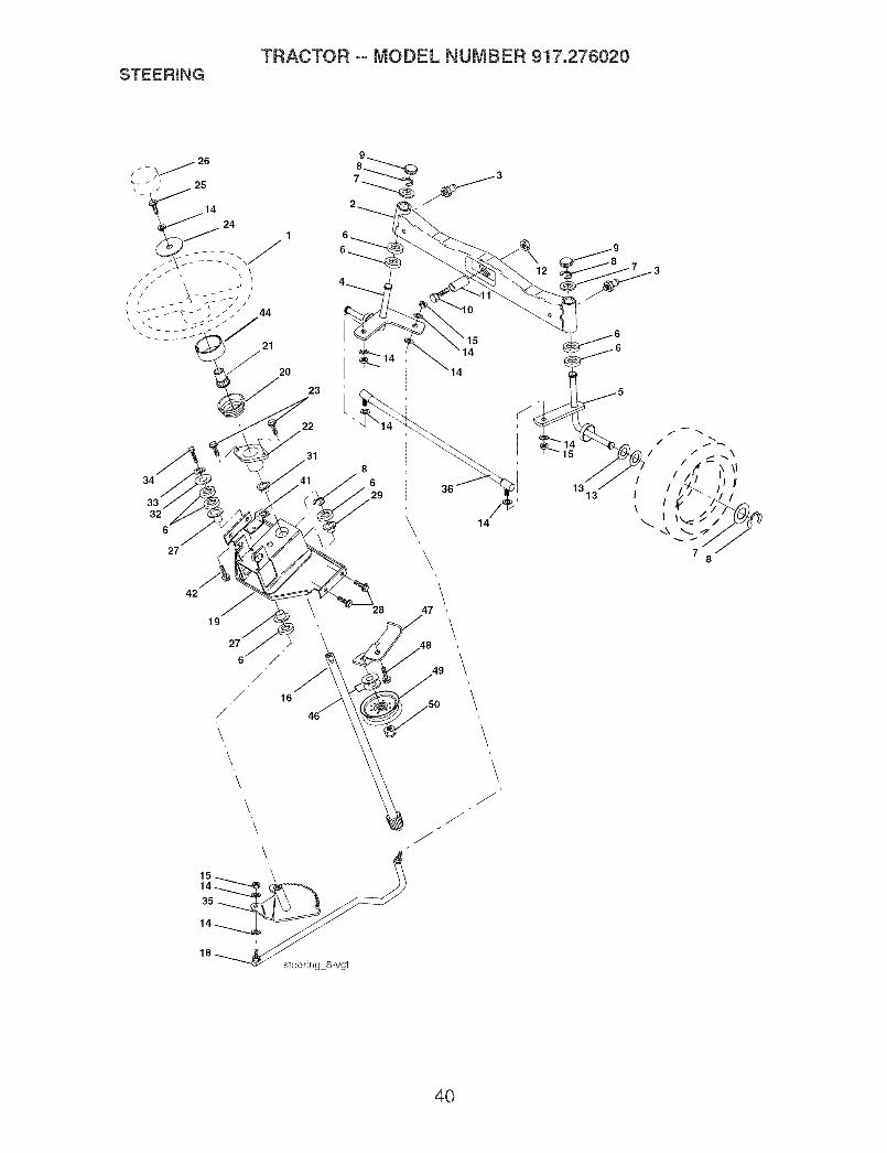
STEERmNGTRACTOR -- MODEL NUMBER 917.276020
26[
\ _ _, 25
_ 14
21
2O
23
34
331
32
6
27
22
31
29
\\
\
2819
/ 6/
47 ,
//48
_so
\
J
14
\\
15
1313
4O

STEERmNGTRACTOR oo MODEL NUMBER 917.276020
KEY PARTNO. NO. DESCFtmPTmON
1 159944X4282 1785573 6855M4 1618495 1618486 6266H7 121748X8 120000299 184946X50510 7478104411 13651812 7390100013 121749X14 STD55113715 STD54153716 14510318 17557219 15601120 163887X42821 15994522 15510523 15292725 7478061626 159946X42827 3366R28 1700061229 104239X31 13813632 1911161033 STD55113134 7478051235 13805936 18679941 15524642 1749050844 160135X42845 1913241146 1913161047 17947148 1706061249 17582050 73900600
Wheel, SteeringAxle Asm. FrontFitting, GreaseSpindle Asm, LHSpindle Asm. RHBearing, Race Thrust HardenWasher 25/32 x 1-5/8 x 16 Ga.Ring, Klip #T5304-75Cap, SpindleBolt, Fin Hex 5/8-11 x 2-3/4Spacer Bearing AxIe FrontNut, Lock FIange 5/8-11 UricWasher 25/32 x 1-1/4 x 16 Ga.Washer, Lock Hvy Hlcl Spr 3/8Nut, Lock Center 3/8-24 UNFShaft Asm. SteeringDraglink VgtSupport Asm. Steering VgtBoot, SteeringAdapter, Wheel SteeringBushing, Strg. BIkScrewBolt, Fin Hex 3/8-16 x 1 Gr. 5Cap, Wheel SteeringBearing, Col. Strg.Screw, 3/8-16 x 3/4Bearing, FlangeBushing, Nytiner SnapWasher 11/32xlx10Ga.Washer, Lock Hvy HIcl Spr 5/16Bolt Fin Hex 5/16-18unc x 3/4Gear, Sector SteeringTie RodBracket Switch Interlock VGT 97Screw Thdro! 5/16-18 x 1/2 TytExtension, SteeringWasher 13/32 x 1-1/20 x 11 Ga.Washer Flat 13/32 x 1 x 10 Ga.Bracket Asm Idler StationaryScrew 3/8-16 x .75Pulley Idler FiatNut Lock Hg 3/8-16 UNC
NOTE: All component dimensions given in U. S.inches 1 inch = 25.4 mm
41

ENGINETRACTOR oo MODEL NUMBER 917.276020
2O
18
28
26 27 39
69
_84
80 82i
12
81
41
8
29
\[ SPARK ARRESTER KIT I
KEY PARTNO. NO.
2 1497238 121361X9 17774810 17528811 17933512 14399615 17911518 179124X42820 177328X42821 17187522 175441X42824 STD55123725 7392060026 3645J27 13927728 7834R29 13718031 145006
DESCRIPTION
Engine (See Breakdown)Kohter Model No=CV730-0017MufflerPulIey VqdlerKeeper Asm= Belt EngineBushingClutch ElectricPuiIey Engine VGT EIect ClutchTank Fuel Rear 5.0Yt/Gt 96Cap Asm Fuel W/GaugeControl ThrottleScrew hwhd Hi-Lo #13-16x3/4Control ChokeWasher Ext Tooth 3/8Nut Keps 3/8 - 24 UNFBushingStem Tank FuelFuel LineSpark Attester KitClip
KEYNO.
3537394O4142434762697O71748O81828384
PARTNO.
10010500123487X1749063617490664126197X
DESCRIPTION
Washer SplitCtamp HoseScrewTT 3/8-16 x 2-1/4 UNCScrew TT 3/8-16 x 4 UNCWasher 1-1/20D x15/32 ID x .250
STD551143 Washer Lock 7/16179953 Bolt Hex 7/16 - 20 x 3.75 Gr.5175287 Spacer Engine146629 Shield Heat Muffler24-041-49 Gasket175545 Tube Exhaust LH175546 Tube Exhaust RH162295 Elbow Street BrassM73030800 Nut FIange148456 Tube Drain Oi! Easy181654 Plug Drain Oil Easy171877 Bolt 5/16-18unc x 3/417060624 Screw 3/8-16 x 1-1/2
NOTE: Al! component dimensions given in U. S.inches 1 inch = 25.4 mm
42

TRACTOR -- MODEL NUMBER 917.276020SEATASSEMBLY
\\\
\\\\\
5
17 12
19
18
seat 6-vgt
KEYNO.
1256781012131415
PARTNO.
180598180166145006STD541437124181X171877180186121246X121248X72050412121249X
DESCRIPTION
SeatBracket, Pivot SeatClip, Push In, HingedNut, Crownlock 3/8-16 UncSpring, Seat CprsnBolt 5/16-18Uncx3/4 w/SemsPan, SeatBracket, Mounting SwitchBushing, SnapBolt, Carriage 1/4-20 X 1-1/2Spacer, Split
KEY PARTNO. NO. DESCRIPTION
16 123740X17 123976X18 1917191219 16636920 124238X21 17185222 7380050038 7111061639 19131610
Spring, CprsnNut, Lock 1/4 Lge Fig Gr. 5Washer 17/32xl -3/16x 12 Ga.Knob, SeatCap, Spring SeatBolt, Shoulder 5/16-18Nut, Lock Hx w/Ins. 5/16-18Bolt Fin Hex 3/8-16 unc x 1Washer Flat 13/32 x 1 x 10 Ga.
NOTE: AUcomponent dimensions given in U. S.inches 1 inch = 25.4 mm
43

DECALSTRACTOR oo MODEL NUMBER 917.276020
1817
15 15
17
nO
22
713
8
25
26\
14 23
12
KEY PARTNO. NO.
1 1640942 149516
3 1862424 1862435 1408376 1336447 1859808 1779189 18628210 15643911 18125212 17755413 18640314 17529115 186725
WHEELS
2
20 11
DESCRIPTION
Decal DashDecaI Battery DNGR/PSNENG AsmDecal Hood RHDecal Hood LHDecal Brake Parking SaddleDecaI MaintenanceDecal EngineDecal EngineDecal, FenderDecal Fender DangerDecal FTRESTDecaI V-Belt Dr SchDecaI ReplacementDeca! V-Bett SchemDecal Hood Side Phi
ANDTmRES
3
47 10
5g
16
KEY PARTNO. NO. DESCRIPTION
16 178482 Decal Deck HVYDTY17 177665 Decal Dash Panel18 164065 Decal Insert Strg19 138047 Decal Battery20 181470 Decal Deck Level22 177914 Decal Engine Logo23 106202X Reflector, Taillight25 177917 Decal Engine LH26 177916 Decal Engine RH- - 179768X428 Pad Footrest LH- - 166960 Decal Drawbar CNTRL- - 179769X428 Pad Footrest RH- - 184739 Owner's Manual, English- - 184740 Owner's Manual, Spanish
KEY PARTNO. NO. DESCRIPTION
1 59192 Cap Valve Tire2 65139 Stem Valve3 106228X624 Rim Asm Front4 8134H Tube, Front (Service Item Only)5 105588X Tire, Front6 278H Fitting Grease (Front Wheel Only)7 9040H Bearing Flange(Front Wheel Only)8 104757X428 Cap Axle (Front Wheel Only)9 106230X Tire Rear10 7154J Tube Rear (Service Item Only)11 106277X624 Rim Asm Rear12 6856M Fitting Grease- - 144334 Sealant, Tire ( 10 oz. Tube)
NOTE: Al! component dimensions given in U. S.inches 1 inch = 25.4 mm
44

TRACTOR -- MODEL NUMBER 917.276020UFT ASSEMBLY
4O
38
39
35 73
34
3132
42
,23
I _ 329
io /\
23
23 7O
KEY PARTNO. NO.
1 121006X2 1800453 1591894 120000225 192920166 711106247 1758308 175831X42110 18389411 17537512 16355223 STD62400824 7335080026 7368080029 15023330 110807X31 STD55103732 13715033 STD56090734 137167
12.-_
/76
DESCRIPTION
Rod Asm. Lever 35 138057Shaft Asm. Lift Vgt 38 155097Lever Asm. Lift Rh 39 123935XE-Ring Truarc #5133-87 40 17060516\Washer 29/32 x 1-1/4 x 16 Ga+ 41 175994BoIt, Fin Hex 3/8-16 x 1-1/2 42 19112410Grip, HandIe FIuted 43 123934XPlunger, Button 70 145212Spring 72 110452XLink Lift 73 73350600Retainer Spring 74 175802Retainer, Spring 75 175805Nut, Jam Hex 1/2-13 Uric 76 175560Nut Crownlock 1/2-13 Uric 77 176205Trunnion, Infin Height 78 175689Nut, Special 79 175378Washer 13/32 x 5/8 x 16 Ga.Spring, Compression Inf HgtPin, Cotter 3/32 x 1/2Rod, Adj Lift
KEY PARTNO. NO. DESCRIPTION
Knob, Inf 3/8-16 UncPointer, Height indicatorPlug, HoleScrew Hex Wsh 5/16-18 x 1Nut, Lift Link 7/16-20',Washer 11/32 x 1-1/2 x 10 Ga+Scale, indicator HeightNut Hex FIange LockNut Push Phos & OilNut Hex Jam 3/8-16 UNCArm Susp+ Rear RHPlate Asm+ Susp+FrontPin, FlangeTrunnion Susp+ ArmTrunnion Susp+ FrontArm, susp+ R LH
NOTE: All component dimensions given in U+S+inches 1 inch = 25+4 mm
45

TRACTOR oo MODEL NUMBER 917.276020MOWER DECK
46
33 _
493652 _ ..49
46
47
116
109
107
24
29\
26
11_ 18
46

TRACTOR oo MODEL NUMBER 917.276020MOWER DECK
KEY PART KEY PARTNO, NO, DESCRmPTmON NO, NO, DESCRmPTmON
1 1849523 1789155 4939M6 178024
8 174365
11 180054
-- 173921
13 17436014 17435815 110485X16 17449317 7211061018 7214050519 13282720 17437821 7368050024 105304X25 17810226 110452X27 180655X42828 1911101629 13149130 17398431 12996332 17786533 17834236 1913131637 17796839 174375
Deck Weldment 42 165723Bracket Asm. Sway Bar 43 174373Retainer Spring 45 180806Arm, Suspension, Rear 46 137729(Sway Bar) 47 180808Bolt 7/16 Asm. Blade 48 174368(The folIowing biades are available) 49 73680600Blade, 48" Hi-lift 50 72110612(For bagging and discharging) 52 175820Blade, 48" Mulching 56 155986(For mulching mowers only) 57 156941Shaft Asm. w/Lower Bearing 97 178515Housing MandreI 98 179479Bearing, Ball, Mandrel 99 184058Stripper Mandre! Deck 100 72110616Bolt RDHD Sq Neck 3/8-16 x 125 107 175294Bolt, Carriage 5/16-18 x 5/8 108 72110404Bolt, Hex Hd, Shoulder 5/16-18 109 73680400Baffle, Vortex Mower 110 175016Nut, Crownlock 5/16-18 UNC 111 174610Cap, Sleeve 116 184219Spring, Torsion 117 174873Nut, Push 118 73930600Deflector Shield 119 19121414Washer 11/32 x 5/8 x 16 Ga. 121 174371Rod, Hinge 126 174372Screw, ThdrolI 130 17000616Washer, Spacer Mower Vented 131 19131606Pulley, Mandrel 133 72110506Nut, FIg. Top Lock Cntr. 9/16 184 173979Washer 13/32 x 13/16 x 16 Ga. - - 174357Pulley, IdIer, 48" PrimaryPulley, Idler, Driven - - 186353
Spacer, RetainerArm, Idler SecondaryCover, Mandrel DeckScrew, Thdroll. 1/4-20 x 5/8V-Belt, Mower, SecondaryV-Belt, Mower, PrimaryNut, Crownlock 3/8-16 UNCBolt, Cam 3/8-16 x 1-1/2 Gr. 5Pulley Idler FlatBar Pnt Adj.Pin Head RivetWasher HardenedSpring Primary DrivePulley Idler"V"Bolt RDHD Sqnk 3/8-16 UNC x 2BaffleBolt, Carriage, 1/4-20 x 1/2Nut, Lock, 1/4-20Arm Spring SecondaryArm Spring Fixed TensionBolt, ShoulderGauge WheelNut, Center!ock 3/8-16 UNCWasher 3/8 x 7/8 x 14 Ga.Spring Secondary DriveArm, Idler, Primary DeckScrew 3/8-16 x 1.0.BIkWasher 13/32 x 1/4 x 16 Ga.Bolt 5/16-18 x 3/4Keeper Belt IdlerMandrel Asm. Service (IncludesKey Nos. 13-15)Replacement Mower, Complete
NOTE: All component dimensions given in U. S.inches 1 inch = 25.4 mm
47

TRACTOR °° MODEL NUMBER 917.276020TRANSA×LE-MODEL NUMBER331-3000
/51 65
68-
85
/60
12_121_
79 SEALANT
97 20W50 01!
205 KIT, SEAL
/
48

TRACTOR oo MODEL NUMBER 917.276020TRANSAXLE--MODEL NUMBER 331-3000
Key Part Key PartNo, No. Description No, No. Description
1 161122 Kit housing main 65 161150Main housing 66 161151Lip sealFlange bearing 67 161152Trunnion bushing 68 161153Cradle bearing 69 169534
2A 193015 Kit, housing dh 71 161155R.H. Housing 73 161156Flange bearing 74 169535Needle bearing (sce1412) 75 161157Lip seal (.875 ID x 1.3 0D x .25) 76 161158
2B 193016 Kit, brake bolt 77 142884Bolt, hex hd 1/4_20 x 1.25 W/patch 79 178322Bolt, hex hd 1/4-20 x 2.25 W/patch 80 161159
3 184703 Kit, center section 81 161160Center section 82 161161Bushing .50 X .60 X .50 83 161162Bushing .90 X 1.02 X .75 84 161163Plate, bypassCheck plug assembly.044 85 161164Check plug assembly, no bleed 87 178323
4 161125 Spacer (BDR BDU 10) 88 1787845 142932 Seal, lip6 142928 Retaining ring 89 1787837 142933 Retaining ring 90 1783268 142934 Bearing, ball 92 17878710 169524 Swash plate (BDP, BDU 10) 93 14296911 173159 Bearing, thrust (10cc) 94 14298012 161126 Shaft, input (310-3000) 95 16953713 142978 Washer, block thrust 96 16953814 142977 Spring, helical compression 9715 169898 Kit, cylinder block (10cc) 106 161166
10CC cylinder block 108 15080010CC piston 110 15081310CC piston springPiston seat washer
21 150786 Block, (BD-21& IHT) 111 15081221CC Cylinder blockPiston seat washer
21CC piston 116 16953921CC piston spring 117 161168
24 161127 Shaft, motor (310-3000) 120 14288325 169526 Bearing, thrust (21cc) 121 19301926 161128 Control arm (310-3000) 122 17832927 161129 Spacer (310-3000) 124 17833028 161130 Gear, 16t pinion 125 17040929 169527 Capscrew 128 17041530 142941 Guide block (BD-21) 129 17041631 169887 Trunnion, tapered square 130 17041132 161133 Bearing, journal 131 14288233 142940 Seal, lip 132 19302034 178318 Return arm (310-3000) 134 17833135 178319 Actuating arm (310-3000) 137 17833336 170421 Bolt, stud 5/16-24 139 16117637 142967 Friction puck 141 17833538 184694 Kit, bypass plate 144 16954539 169529 Bypass actuator (IHT) 145 16954640 142945 Seal, lip 146 16954741 142952 Bypass arm 151 17041742 142953 Retaining ring 152 17833643 142965 Pin 153 17043444 150797 Bolt 3/8-24 x 2-1/2 155 17833746 184702 Spring, neutral (310-3000)48 178320 Puck, adjusting (310-3000)50 178343 Screw hex head washer cap screw
dZT) 1/4-20 x 3/451 169530 Lower cover 157 16954852 169531 Geroter assembly 169 18470153 144581 O-ring 203 17833854 161139 Charge pump housing55 178321 Kit, filter
Gasket .10 X .16 X 4.24Filter
56 169533 Charge manifold 310-300057 161142 Retainer, motor bearing (310-3000)58 161143 Pin carrier (310-3000)59 161144 Gear, 15t planet (310-3000)60 161145 Gear, 67t spur (310-3000)61 161146 Gear, 21t sun (310-3000)62 161147 Plate, planet thrust (310-3000) 900 17605663 161148 Gear, 51t ring (310-3000)64 161149 Carrier, planetary (310-3000)
Gear differential bevel (310-3000)Gear, differential bevel pinion(310-3000)Shaft, differential (310-3000)Plate, differential thrust (310-3000)Bearing, flange (310-3000)Washer, flat (1.00 Id) (310-3000)Nut, 5/8-18 hex jam (310-3000)Bearing, ball (310-3000)Seal, lip (310-3000)Shaft, axle (310-3000)Washer, flatSealant tube
Screw, torx head 5/16-18 (310-3000)Bearing, needle (210-3000)Washer, flat (0.880 ID) (310-3000)Ring, retaining (310-3000)Seal, lip (.875 ID x 1.38 OD x .25)(310-3000)Brake disc (310-3000)Washer (310-3000)Screw, 5/16-24x 1 1/2 socket head cap(310-3000)Bearing, ballSpacer, locating (310-3000)Screw (310-3000)SpringSpacerNut, nylon insert hex lock 5/16-24Bearing, sleeve (310-3000)20W-50 oil 122 ozSpacer, trunnion (310-3000)Plug, plastic shippingO-ringFitting, plastic hoseO-ringBreather vent, plasticVent, plasticVent capRing, retaining (310-3000)PinBrake puckBolt, hex hd 1/4-20 x 1.25 W/patchKit brake yokeBrake arm
Pin, brake actuatingNut, castle 5/16-24Pin, cotter 3/32x3/4Spacer, brake torsion springBrake puck plateBolt, hex hd 1/4-20 x 2.25 W/patchBrake comp. SpringPin, spring (310-3000)Washer, flatSpring, brake arm biasO-ringSpring, reliefSteel ball 7/16
Brake springBrake pull rodPlug, straight thread 9/16-18Kit, fan/pulleyNut, jam 1/2-20Washer, OD slotted .53 X 1.63 X .06PulleyFan
O-ringPin, spring 5/16 x 1.75Kit, sealLipsea115xSx37Lipsaa112x25x7Lipsea110x25x7O-ring .103 X 1.862Seal 25 x 52 x 10Lip seal .875 ID x 1.30D x .25O-ring .070 X .239Kit, o-ring, manifoldPin, spring 5/16 x 1.75Pin, spring 1/4 x 1,00Transaxle
Note: All Component Dimensions Given In U.s. Inches1 Inch = 25,4 MM
49

TRACTOR oo MODEL NUMBER 917.276020KOHLER ENGmNE=MODEL NUMBER CV730,TYPE NUMBER 0017
CYLINDER HEAD, VALVE AND BREATHER i
31
30
5
7--
CRANKCASEJ
23_ 5
13 _:5
12j_
,/,1
9
3
/
,¢_%j
°- X_7
0
5O

TRACTOR °° MODEL NUMBER 917.276020KOHLER ENGINE =MODEL NUMBER CV730,TYPE NUMBER 0017
HEAD/VALVE/BREATHER
KEY PARTNO. NO. DESCRiPTiON
CRANKCASE
KEY PARTNO. NO.
1.
1, 24-033-03-S Kit, breather cover w/gasket 2,(Includes 2, 3)
2. 24=041=23=S Gasket, breather 3.3. 24=096=87=S Cover, breather 4.4. M=645020-S Screw, hex. flange 5.
M6xt .0x20 (4)5. 25 139 60-S Plug, hex. ctsk. 1/8"6. 25-351-01-S L#ter, valve (4) 6.7. 24-755-66-S Kit, valve train (Incnudes 8,
11, 12) 7.8. 24-411-05-S Rod, push (4) 8.9. 24-041-37-8 Gasket, cylinder head (2)10. 24-318-72-S Head assembly, #2 cylinder 9.11, 25-186-01-S Arm, rocker (4)12. 24o599-01-S Pivot, rocker arm (4)13. 12 686 16-8 Screw, hex. flange
M10x1.5x90 (4)14. M-640034-8 Screw, hex. flange
M6x1.0x34 (4) 10.15. 24-755-74-8 Kit, valve cover = p_ain 11.
(Includes 16,17) 12.16. 24-153-23-8 O-Ring17. 24-086-32-S Screw, shoulder M6x1.0x30 13.
(4) 14.18. 24-445-01=S Strap, _ifting 15.19. 24.016-01-S Valve, exhaust (Std.} (2) 16.
24.016-02-S Valve, exhaust (.25) (2) 17.20. 24.017-01-S Valve, intake (Std.) (2) 18.
24.017-02-S Valve, intake (.25) (2)21. 66-032-05-S Seal, valve stem (2) 19.22. 235011-S Retainer, spring (4) 20.23. 24-089-02-S Spring va_ve (4)24. 12-173-01-S Cap, valve spring (4) 21.25. 12-755-03-S Kit, retainer (4) 22.26. 24-318-69-S Head assemMy, #1 cylinder27. 24 605 01-S Liner, exhaust port (2) 23.24.28. 24=755-76=8 Kit, valve cover - breath 25.
er (Includes 16,17,29) 26.29. 25-313=03=S Grommet, rubber 27.30. 24-755-57-8 Kit, breather separator
(Includes 29,31-34)31. M-545016-8 Screw, hex. f_ange
M5x0.8x16 (2)32. 24-445-01-S Strap, breather33. 24-126-44-S Bracket, breather separator34. 24-112-12-S Spacer35. 24-326-55-S Hose, breather
DESCRIPTION
24-032-01-8
24-294-13-S24-380-13-S24=067=13-S24=067=14-S24-874-08-S
24=874=16-S24-108-05-S24-018-01-S12-422-09 =S12-422 =13-S12-422-07 ,S12-422-08 =S12=422 =10-S12=422-11-S12-422-12-S24-012-16-S52-139-09-SM-545010-S
24-018=04-S24-402-05-S12-153=01-S24-126=19-S12-123=04-SM-545016-S
12-153-02-S24-038-04-S
24-755-46-S25 153 02=S24-018-09°SM-931010-S28-032-09-S24=468 . 15=S24-144-38-S
Seal, front oilCrankcase (USE: MiniMock24 782 14)FittingPin, _ocating(6)Connecting Rod (Std.) (2)Connecting Rod ¢25) (2)Piston w/Ring Set (Std.) (2)(Includes 7, 8)Kit, piston w/ring set 008)Ring Set (Std. & .08) (2)Retainer, piston pin (4)Shim, camshaft (A.R.)Shim,Shim, camshaft CA.R.}Shim, camshaft (A.R.)Shim, camshaftShim, camshaft (A.R.)Shim, camshaft (A.R.)CamshaftPlug cupScrew, hex. fangeM5x0.Sxl0 (2)Retainer, reed (2)Reed, breather (2)O-Ring, _oweroi_fill tubeBracket, oil fill tubeTube, oil fillScrew, hex. flangeM5x0.8x16O-Ring, upper oil fill tubeDipstick assembly (Includes21,22)Kit, oi_1i_cap (_nc_udes22)O-Ring, dipstickRing, retainerWasher, nybn (top)Seal, governor cross shaftWasher (bottom)Shaft, governor cross
NOTE: All component dimensions given in U.S.inches 1 inch = 25.4 mm
51

TRACTOR ooMODEL NUMBER 917.276020KOHLERENGINE=MODELNUMBERCV730,TYPENUMBER0017
I,
BLOWER HOUSING AND BAFFLES i
?
7
6
52

TRACTOR -- MODEL NUMBER 917.276020KOHLER ENGiNE=MODEL NUMBER CV730,TYPE NUMBER 0017
IGNITION/ELECTRiCAL
KEY PARTNO. NO. DESCRmPTmON
SLOWER HOUSING & BAFFLES
KEY PARTNO. NO. DESCRiPTiON
1. 24-027-114-S Housing, blower (_nc_udes 2)1. 54-755-15-S Kit, grass screen 2. 24-100-01-S Nut, plastic (2)
(inciudes 2-4) 3. M-551016-S Screw, hex. _Hange2. M-403025-S Screw, hex. cap M4x0.7x25 M5x0.8x16
(4) 4. M-545016-S Screw, hex. fiange3. X-25-92-S Washer, p_ain 5/16" (4) M5x0.8x16 (3)4. 24-112-04-S Spacer, grass screen (4) 5. M-545020-S Screw, hex. fiange5. 25-086-47-S Be_t, shoulder M6x1.0x16(4) M5x0.8x20 (4)6. 24-157-08-S Fan7. 12-086-14-S Screw, hex. flange 6. M-645016-S Screw, hex. flange
M6x1.0x16 (6)M10xl.5x46 7. 24-146-16-S Plate, backing - # 2 side
8. 12-468-03-S Washer, piain 3/8" 8. 24-146-20-S P_ate, backing - # 1 side9. X-42-15-S Key 9. 24-063-20-S Baffle, cylinder barrei - # 210. 24-025-01 -S Fiywheei side11. 25-403-03-S Rectifier-regulator 10. 24-063-58-S Baffle, cylinder barrei- # 112. X-25-92-S Washer, piain 3/16" (2) side13. 24-086-18-S Screw, phillips hd. 11-16x7/8
(2) 11. M-545010-S Screw, hex. flangeM5x0.8xl0 (2)14. 236602-S Connector (3 contact) 12. 24-063-14-S Baffle, valley - #2 side15. 12-132-06-S Spark Piug (2) 13. 24-063-60-S Baffle, valley- #1 side16. M-548025-S Screw, hex. cap M5x0.8x25
(2) NOT ILLUSTRATED17. 54-755-09-S Kit, 15 amp stator 24-096-85-S Cover, blower housing
(inciudes 18) 25-086-91-S Screw, tapping 10-16xl/2"18. 24 126 71-S Bracket, stator wire19. 48-154-02-S C_ip, cable (2)20. X-25-63-S Washer, piain 1/4"21. 24-584-01-S Module, ignition (2) AIR INTAKE/FILTRATION
22. M-545020-S Screw, hex fiange KEY PARTM5x0.8x20 (4} NO, NO, DESCRIPTION
23. 235173-S CHip,cabie
NOT ILLUSTRATEDX-22-11 -S24-176-82-S24-518-12-S
25-454-03-S
Washer, Hock1/4"Harness, wiringLead, biack (rect,-reg, 6"- 12gaugeinsulated grip barrei eyelets)Tie, wire (3)
1, 54-755-01-S
2. 25-341-03-S3. 24-153-20-S4. 24-096-67-S5. 12-100-01-S6. 24-096-01-S7. 231032-S8. 24-083-05-S9. 24-083-03-S10. 24-109-09-S11. 24-041-13-S12. 24-094-34-S13. 24-041-14-S14. 24-164-51-S
15. 24 041 52-S16. 24 153 27-S17. M-651040-S
18. 24 126 130-S19. M-545010-S
20. 24-063-51-S
Kit, knob with sea_(inciudes 2,3)Knob, coverO-RingCover, air cieanerWing NutCover, inner air cieanerSeal breatherPrecieaner, elementE_ement, air c_eanerCup, fuei spit-backGasket, fuel spit-back cupBase, air cieanerGasket, air cieaner baseManifoid, intake (inciudes15,16)Gasket, carburetorO-Ring, intake port (2)Screw,, hex. flangeM6x1.0x40 (4)Bracket, air dearer baseScrew, hex. fiangeM5x0.8xl0 (2}Baffie, spit-back cup
NOTE: All component dimensions given in U.S.inches 1 inch = 25.4 mm
53

TRACTOR °° MODEL NUMBER 917.276020KOHLER ENGmNE=MODEL NUMBER CV730,TYPE NUMBER 0017
STARTING SYSTEM I
7
ENGUNE CONTROLS I
6
4\ft 27
\
""18
@j
_j6@--5
_2
54

TRACTOR oo MODEL NUMBER 917.276020KOHLER ENGmNE-MODEL NUMBER CV730,TYPE NUMBER 0017
STARTmNG SYSTEM OiL PAN/LU BRiCATiON
KEY PART KEY PARTNO, NO, DESCRiPTiON NO, NO,
1. M-839080-S Screw, hex. flange 1.MSx1.25x80 (2)
2. 25°098°09°S Starter, solenoid sMft (in 2.dudes 3-7)
3. 25 086 113-S Screw, extemaH 3.torx hd. (3) 4.
4. 25-435-05-S Kit, solenoid (inciudes 3) 5.5. 25-755-33-S Kit, pinion drive (inciudes 6) 6.6. 25-141-05-S Ring7. 25-221-01-S Kit, brush 7.
8.ENGINE CONTROLS
KEY PARTNO. NO. DESCRIPTION
1. 24 211 03-S Boit, round head squareneck
2. 24-090-33-S Lever, governor3. M°641060°S Nut, hex. fiange M6x1.04. 24°089-01 °S Spring, Hnkage5. 25°158°08°S Bushing, Hnkage retaining6. 24°079°04°S Linkage, throttie7. 25°158°11°S Bushing, throttle Hnkage8. M°545016°S Screw, hex. flange
M5xO.8x169. M°547050°S Nut, hex. lock M5xO.810. 24°089°03°S Spring, choke return11. 24°126°56°S Bracket, control12. M°645016°S Screw, hex. flange
M6x1.0x16 (4)13. 12°237°01°S CHamp, came (2)14. 24°086°43°S Screw, hex, flange
M5xO.8x16 (2)15. 24°090°07°S Lever, throttle actuator16. X°20°1°S Washer, lock 1/4"17. M°541050-S Nut, hex. flange M5xO.818. 24°468°01°S Washer, plain 5.5 mm (3)19. 24°089-45-S Spring, governor20. M°446030°S Nut, hex M4xO.721. 24°090°13-S Lever, throttle control22. M°545020°S Screw, hex. flange
M5xO.Sx2023. 24°089-51 °S Spring, throttle limiter24. 24°090-05°S Lever, choke25. 41°468°03°S Washer, spring 1/4"26. M°403025°S Screw, hex. cap M4xO.7x2527. 24°079°02°S Linkage, choke
DESCRIPTION
g.
10.11.12.13.14.15.16.17.
18.
19.
24°199°07°S
24°393°37°S
24°381 °11°S24 153 01°SM°631005°SM°645025°S
24°162°26°S24°043°12°S
12°380°01oS52°448°02°S12°144°02°S24°153-08°S25°139°62°S24°136°01°S12°050°01-S52°032°08°S24°086 °17°s
24°086 °16°S
25°139°57°S
Pan assembly, oil(Includes 2-11)Oil pump assembly (Indudes 3,4)Tube, oil pickupO-Ring, oil pumpWasher, plain 6 mm (2)Screw, hex. flangeM6x1.0x25 (2)Screen, oilKit, governor gear w/pin(includes 9)Pin, governor regulatingTab, lockingShaft, governor gearO-RingPlug, hex. ctsk. 3/8"Nipple, oil filterFilter, oilSeal, oil (PTO end)Screw, hex. flangeM8xl.25x45Screw, hex. flangeMSx1.25x45 (9)Plug, sq. hd. solid 3/8"N.RT.E
NOTE: All component dimensions given in U.S.inches 1 inch = 25.4 mm
55

TRACTOR oo MODEL NUMBER 917.276020KOHLER ENGmNE=MODEL NUMBER CV730,TYPE NUMBER 0017
CRANKSHAFT J
2=@
FUEL SYSTEM 1
EXHAUST I
\
8
s _
l7
56

TRACTOR oo MODEL NUMBER 917.276020KOHLER ENGmNE=MODEL NUMBER CV730,TYPE NUMBER 0017
CRANKSHAFT
KEY PARTNO, NO,
1. 24-014-72-S2. 52=189=09=8
EXHAUST
KEY PARTNO, NO,
I.2.= =
= =
DESCRiPTiON
Crankshaft (includes 2)Plug, cup
DESCRiPTiON
24=041=02=S Gasket, exhaust (2)25=072=04=S Stud, M8x1.25x33 (4)24 782 23 Miniblock24 755 113=S Gasket Set
FUEL SYSTEM
KEY PARTNO. NO.
24-853-90-S
2. 24-041-52=S3. 24-058-90
4. 24 041 14-S5. M-629095=S6. M-641060-S7. 25-353-03-S8. 25-237-14-S9. 24-086-12-S
10. 24-393=16-S1. 24-100-01-S
12. 24-353-03-S13. 15-353=04-S14. 24-050-02-S
NOT ILLUSTRATED24 234 02-S24 757 18-S24 757 19-S24 757 20-S24 757 21-S24 757 22-S
DESCRIPTION
Kit, carburetor w/gaskets(includes 2-4)Gasket, carburetorCarburetor assembly(For information only notavailable separately)(Service with 24 234 02=8 &Kits 24 757 18-8, 24 75719-S, 24 757 20-S, 24 75721-S, & 24 757 22-S)Gasket, air cleaner baseStud, MSx1.0x95 (2)Nut, hex. flange MSx1.0 (2)Line, fuel 14"Clamp, hose (6)Screw, hex. cap. M6x1.7x18(2)Pump, fuel- pulseNut, plastic (2)Line, fuel 10-5/8"Line, fuel 11-1/2"Filter, fuel
Bowl, floatKit, overhaulKit, choke repairKit, gasketKit, accelerator pump repairKit, fuel shutdown solenoid
NOTE: All component dimensions given in U.S.inches 1 inch = 25.4 mm
57

58

SUGGESTED GUIDE FOR SIGHTING SLOPES FOR SAFE OPERATION
ONLY RIDE UP AND DOWN HILL,NOT ACROSS HILL
15 DEGREES MAX.
i_ WARNING: To avoid serious injury, operate your tractor up anddown the face of slopes, never across the face. Do not mowslopes greater than 15 degrees. Make turns gradually to preventtipping or loss of control. Exercise extreme caution whenchanging direction on slopes.

;;;;;;;;;;;;;;;;;
i i! ililililililililililililililili
Your Home
For repair - in your home - of all major brand appliances,lawn and garden equipment, or heating and cooling systems,
no matter who made it, no matter who sold it!
For the replacement parts, accessories andowner's manuals that you need to do-it-yourself.
For Sears professional installation of home appliancesand items like garage door openers and water heaters.
1-800-4-MY-HOME ® Anytime, day or night
(1-800-469-4663) (U.S.A. and Canada)www.sears.com www.sears.ca
Our Home
For repair of carry-in products like vacuums, lawn equipment,and electronics, call or go on-line for the nearest
Sears Parts and Repair Center.
1-800-488-1222 Anytime, day or night (U.S.A. only)
www.sears.com
!i!i!i!i!i!i!i!i!i!i!i!i!i!i!i!i!i!i!i_i_iiiiiiiiiiiiiiiiiiiiiiiiiiiiiiiiiiiiiiiiiiiiiiiiiiiiiiiiiiiiiiiiiiiiiiiiiiiiiiiiiiiiiiiiiiiiiiiiiiiiiiiiiiiiiiiiiiiiiiiiiiiiiiiiiiiiiiiiiiiiiiiiiiiiiiiiiiiiiiiiiiiiiiiiiiiiiiiiiiiiiiiiiiiiiiiiiiiiiiiiiiiiiiiiiiiiiiiiiiiiiiiiiiiiiiiiiiiiiiiiiiiiiiiiiiiiiiiiiiiiiiiiiiiiiiiiiiiiiiiiiiiiiiiiiiiiiiiiiiiiiiiiiiiiiiiiiiiiiiiiiiiiiiiiiiiiiiiiiiiiiiiiiiiiiiiiiiiiiiiiiiiiiiiiiiiiiiiiiiiiiiiiiiiiiiiiiiiiiiiiiiiiiiiiiiiiiiiiiiii
To purchase a protection agreement (U.S.A.)
or maintenance agreement (Canada) on a product serviced by Sears:
1-800-827-6655 (U.S.A.) 1-800-361-6665 (Canada)
Para pedir servicio de reparaci6na domicilio, y para ordenar piezas:
1-888-SU-HOGAR SM(1-888-784-6427)
Au Canada pour service en frangais:1-800-LE-FOYER Mc
(1-800-533-6937)
wwwsearsca .....
© Sears,Roebuckand Co.
® Registered Trademark / TMTrademark / SMService Mark of Sears, Roebuck and Co.
® Marca Registrada / TMMarca de F,_brica / SMMarca de Servicio de Sears, Roebuck and Co.MCMarque de commerce / MDMarque deposee de Sears, Roebuck and Co.
184739 Re',/. 7 8.4.04 JHiRDiMH Printed in U.S.A.