OWNER’S MANUAL - Best Pool...
24
OWNER’S MANUAL Should you the installer or owner be unfamiliar with the correct installation or operation of this type of equipment you should contact the distributor/manufacturer for the correct advice before proceeding with the installation or operation of this product. Pantera Series II High Rate Sand Filter
Transcript of OWNER’S MANUAL - Best Pool...

OW
NE
R’S
MA
NU
AL Should you the installer or owner be unfamiliar with the correct
installation or operation of this type of equipment you should contact
the distributor/manufacturer for the correct advice before proceeding
with the installation or operation of this product.
Pantera Series IIHigh Rate Sand Filter

Technologically advanced solutions for moving and treating water in the Home, Garden, Pool and Spa.
Innovative Stock and Crop water management solutions for Primary Industries.
Water movement products for Building services, Emergency services and Original Equipment Manufacturers.
Relax - you’ve bought an ...Congratulations on your decision to purchase an Onga product. Onga is one of the best know brands in its fi eld, with a proud local and international reputation.
Onga is a brand for reliability, value for money and technological innovation. You will fi nd Onga product wherever people need to move water in 3 broad markets covering:
1

1. Continual Product Improvement
We employ the best engineers both in Australia and around the world to develop new and better ways to take water further.
2. Operational Excellence
There is only one standard that we set ourselves for both product quality and the quality of our service. That standard is excellence... to have no-one better than us at what we do... nothing short of that is acceptable. Our commitment to quality is reinforced with our ISO 9001:2000 accreditation.
3. A Fair Price
Onga products are neither the cheapest nor the most expensive in their fi eld. Our products do, on the other hand, always represent very good value for money; they always have and they always will.
4. Our Team of Dealers
The hand picked authorised Onga dealer network throughout Australia and worldwide are second to none. We invest considerable time and resources training and supporting them through the Onga Training Academy.
2

TABLE OF CONTENTS
Model Data 4
Installation 6
Operation 12
Service and Maintenance 14
Troubleshooting 19
Warranty 21
3

4
Model Data
The operator must be provided with the owner’s manual. This must be read before operation and followed during operation.These instructions are a guide only. Users not familiar with pool equipment should seek advice for suitably qualifi ed persons with experience in pool equipment installation.
Manufactured in Australia, the Onga Pantera II sand fi lter is made from UV stabilised polyethylene. The reputation of durability and performance makes the PanteraII range fi rst choice for quality pool builders.
Technical Data
P221 P225 P229 P233
Filter Diameter (mm) 535 635 735 835
Filter Area (m2) (Internal) 0.205 0.293 0.397 0.517
Max Working Pressure (kPa) 280 280 280 280
Maximum Flow Rate (lpm) 165 235 320 415
Design Flow Rate (lpm) 145 205 280 365
Min Flow Rate for Backwashing (lpm) 125 175 240 310
Recommended Pool Volume (litres):
Minimum 30000 45000 60000 75000
Maximum 65000 90000 120000 160000
Filter Height (to top of valve)* 840 960 1090 1170
Required mass of fi lter media:
Sand (16/30 grade) (kg) 90 140 185 220
Zeolite (kg) 70 105 140 165
Valve Size (connection to PVC) (mm) 40 40 50 50
*It is recommended to ensure there is at least 600mm of clear space above the top of the fi lter to facilitate servicing.
Due to excessive cycling, this fi lter is not suitable for use on inbuilt In-fl oor Cleaning Systems.

Filter Application - General Information
This filter is designed for use in domestic/residential swimming pool installations with correctly sanitised fresh or salt chlorinated water. Suitable for use with sand or Zelbrite fi lter media.
1. Locate the fi lter system as close to the pool as practical.2. Place the fi lter on a level stable foundation, preferably a concrete pad or paving.3. Position all equipment to provide ease of access for future servicing.4. Protect the fi lter and pump from weather and direct sunlight by ensuring that they are properly housed.5. Ensure there is suffi cient space to provide adequate ventilation to electric pump motor.6. Clean a new pool as well as possible before fi lling pool and operating fi lter. Excess dirt and large particles of foreign matter in the system can cause serious damage to the fi lter and pump.7. Ensure pump is compatible with fi lter specifi cations.
5

6
Installation
Hazardous PressureIncorrectly installed or tested equipment may fail, causing severe injury or property damage. Read and follow instructions in owner’s manual when installing and operating equipment.Have a trained pool professional perform all pressure tests.
All glued fi ttings and pipe work should be allowed to dry to atmosphere for 24 hours before closing the installation. Failure to do so could cause injury or installation failure.
The fi ttings on these fi lters are constructed of ABS. Some PVC jointing compounds are incompatible with ABS possibly causing failure to the product. Check compound suitability prior to use.
Installation & Assembly of Internal Components
Installation of fi lter should be only carried out by qualifi ed personnel. Ensure that the under-drain assembly (hub, laterals & tube) are properly assembled & installed prior to adding fi lter media (sand).
Hazardous Pressure!Can cause severeinjury or major property damage from tank explosion.
BEFORE WORKING ON THE FILTER:
1. Stop Pump2. Release all pressure from system, by turning valve handle to waste.
WARNINGFilter pumps require hazardous voltage which can shock, burn, or cause death.
BEFORE WORKING ON THE PUMP OR MOTOR:
Disconnect power to motor.

7
1. The fi lter internals comprise of a collector hub and eight (8) laterals, which are supplied packaged seperately with the collector hub and are stored inside the fi lter tank prior to shipment.
2. Carefully inspect the laterals and hub prior to assembly for any visible defects.
3. To assemble the laterals and hub please use the following steps. (The connection between the hub and the lateral is completed inside the fi lter tank - refer to diagram on following page)
For P221100 & P225100 Models only: Push in and align the male tab on the lateral with the female slot in the hub. Rotate the lateral clockwise until the tabs engage with an audible “click”. Repeat this process for all 8 laterals.
For P229200 & P233200 Models only: Begin by assembling each of the Y-Pieces and the end caps. Place a washer into the socket of the end cap then align the female slot on the end cap with the male tab on the lateral. Push the end cap onto the branch of the Y-piece. Rotate the Y-piece clockwise until the tabs engage with an audible “click”. Push in the tapered pin (16 supplied) to lock the end caps in place. Repeat this process for all 16 end caps on the 8 laterals (2 per lateral).
To assemble the Y-piece to the Hub place a washer into the socket of the Y-piece, then align the female slot on the lateral with the male tab on the hub. Push the Y-piece onto the Hub. Rotate the lateral clockwise until the tabs engage with an audible “click”. Push in the tapered pin (8 supplied) to lock the lateral in place. Repeat this process for all 8 laterals.
Hub Lateral Model P229 & P233
Hub Lateral Model P221& P225

8
Important: Ensure slotted side of laterals face downwards from hub after fi nal assembly, and prior to fi lling with sand.
Steps for Installation of Filter Internals
.
B. Insert assembly
into top of filter
tank.
C. Hold assembly up near
top of tank and add remining
laterals.
After alllaterals aresecurely insockets,positionassembly inthe centreon thebottom ofthe tank.
A. Insert first lateral into socket; twist
clockwise 1/4 turn to lock lateral into
hub. Lateral is correctly installed when
slots face down.

9
Loading Sand Media
1. To keep sand out off collector assembly, place plastic sand shield over top of collector tube before pouring sand into fi lter (See diagram below).
2. To support laterals and prevent lateral breakage during loadings, fi ll tank about half full of water before loading sand.
3. Pour sand into fi lter, making sure that the sand is of the correct type and quantity for the particular fi lter model (Refer fi lter label).
Make sure gasket area on top of tank is free of sand before installing valve.
4. Before installing valve, double-check that the correct quantity of sand has been loaded.
5. Remove plastic sand loading shield and keep for future use.
Installation of Multi-Port Valve
1. Install o-ring on valve fl ange; make sure o-ring is clean, and has no nicks, tears, or scrapes and lubricate with silicon based lubricant.
2. Make sure tank and valve fl anges are clean and free of sand; put valve on top of tank. Vertical pipe of collector assembly inserts into base of valve.
3. Install clamp; make sure knob is positioned for easy access for fi lter maintenance. Valve port labelled “Pump” should point toward pump.

10
Hazardous pressure. Clamp will not hold unless it is seated properly! DO NOT START PUMP until clamp ends are 1/4” (6mm) apart or less.
4. Tighten clamp knob until clamp ends (under bolt) are 1/4” (6mm) apart. Tap around outside of clamp with a mallet to help seat clamp.
5. Connect pipe from pump discharge to valve port labelled “PUMP”; use union half provided. Assemble union as follows for leak free operation: - o-ring and sealing surfaces must be clean. - Assemble hand tight only (No wrenches). - NO pipe compound or tefl on tape on unions.
6. Complete all plumbing connections, using 1 1/2” (P221100 & P225100) or 2” (P229200 & P233200) pipe to reduce pressure losses as much as possible. - Pipe from valve RETURN port to pool return. - Pipe from valve WASTE port to waste. - Suction piping from pool to trap inlet on pump.
7. System is ready to start up.

8. If you notice a leak around the clamp area after 15-30 minutes of running, repeat steps 3-4.
If there are leaks from beneath valve/clamp area, STOP PUMP, release all pressure by turning valve handle to ‘waste’, remove clamp and valve and clean sealing surfaces.
11

Operation
The fi lter operator or owner must be provided with this owner’s manual. This must be read before operation, and followed during operation.
Incorrectly installed or tested equipment may fail, causing severe injury or property damage. Read and follow instructions in owner’s manual when installing and operating equipment. Have a trained pool professional perform all pressure tests.
Hazardous Pressure. To avoid explosion and possible severe or fatal injury, fi lter system pressure must not exceed 40psi (280kPa) under any circumstances. NEVER test this fi lter system with compressed air; never operate system with water temperature above 350C.
To prevent equipment damage and possible injury, turn pump OFF before changing valve position.
Do not add chemicals directly into the pool skimmer. Adding undiluted chemicals may damage equipment and void warranty.
Multi-Port Valve Settings
12

Startup/Operation
1. Open system valve and make sure pump is fi lled with water. Make sure pool water level is 2” (50mm) above bottom of skimmer opening. 2. With pump OFF, set valve to ‘BACKWASH’ position.
3. Start pump, circulating water through fi lter to waste. NOTE: To prevent pump running dry, be sure water level never drops below bottom of skimmer inlet. Add water to pool if necessary to keep skimmer fl ooded while back-washing and rinsing.
4. Backwash until water runs clear (1-5 minutes)
5. Stop Pump; set valve to ‘RINSE’ position.
6. Start pump; run pump for 1 minute. Note: for Zelbrite repeat steps 1 through to 6 three times.
7. Stop pump; set valve to ‘FILTER’ Position.
8. Filter is now ready for service.
9. Record clean starting fi lter pressure gauge reading as a reference.
10. For new pools, backwash once a day until pool water is sparkling clear. Backwash when pressure gauge shows 5 to 7 psi (35 to 50kPa) higher than clean starting pressure (refer to step 9).
13

Service & Maintenance
Hazardous pressure. Stop pump and release all pressure from system before working on fi lter, valve, or clamp.
General: Wash outside of fi lter with a mild detergent and water. Rinse off with hose.
DO NOT use solvents to clean fi lter; solvents may damage components in system.
Inspect sand/media bed at least once a year to remove foreign material which has not been back-washed out of the system.
NOTE: When the sand/media bed gets hard and crusty on top, remove all the old sand/media and replace it with new sand/media. Alternatively, if the pressure gauge does not return to within 40kPa of clean fi lter pressure after back-washing it is time to replace the fi lter media.
Weekly Pool Equipment Inspection
1. Check pressure during operation. When pressure is 5 to 7 psi (35 to 50 kPa) higher than clean operating pressure, backwash fi lter (see instructions under Startup/Operation, page 12).
2. Except during hot weather with heavy skimmer loads, operating fi lter 6 to 12 hours per day should be suffi cient. Carefully monitor water chemical balance and follow recommendations of your local pool professional.
Water Maintenance
Keep water level at least 2” (50mm) above bottom of skimmer opening. Failure to do so can allow air to enter system, causing pump to lose prime and air to enter fi lter.
Maintain pH between 7.2 and 7.6 in pool.
14

To prevent damage to system components, keep water temperature below 380C at all times.
Vacuum Pool
(Refer cleaner operating manual or consult your local pool professional)
1. Fill vacuum hose by submerging in water from one end to the other.
2. To vacuum, insert hose into skimmer suction manifold or into vacuum line in pool wall. See instructions provided by the pool builder or pool manufacturer. Start pump, making sure it is primed and pumping.
3. After vacuuming, clean pump trap basket to remove accumulated debris, then check fi lter pressure gauge. If reading is 5 to 7 psi (35 to 50 kPa) higher than initial operating pressure, backwash fi lter.
Lower or Drain Pool
1. Turn pump ‘OFF’ ; set valve handle to ‘WASTE’.
2. Use Vaccuum cleaner hose and head.
3. Start pump; run until pool is lowered to desired level.
4. Turn pump ‘OFF’ set valve handle to ‘FILTER’
5. Start pump.
Multi-Port Valve Service
If valve is leaking during normal operation it will need to be repaired by an authorised Pentair Water service technician.
Valve Removal
Hazardous pressure. Stop pump and release all pressure from system before working on fi lter, valve, or clamp.
15

16
NOTE: If Multi-Port Valve is below pool water level, close suction and discharge valves before disassembly to prevent draining pool.
1. Disconnect piping from pump and pool.2. Remove clamp.3. Remove valve from fi lter top.4. To re-install valve, follow instructions, BE SURE to follow clamp tightening instructions.

17
Tank Assembly
1
2
4
5
6
7
3
1
23
4
5
6
7
P221 P225

18
Item Description P221 P225 P229 P233
1 Multiport Valve assembly 1 1 1 1
2 o-ring - tank fl ange 1 1 1 1
3 Handle - vee clamp 1 1 1 1
4 Vee Clamp 1 1 1 1
5 Filter Tank assembly 1 1 1 1
6 Collector hub 1 1 1 1
7 Lateral assembly 8 8 0 0
8 Lateral ‘Y’ Piece 0 0 8 8
9 Locking Pin - lateral 0 0 24 24
10 End Cap - lateral 0 0 16 16
Washer (Laterals) 0 0 24 24
P229 P233
1 2
43
5
6
910
8
1 2
43
5
6
910
8
Not Shown on diagram
19
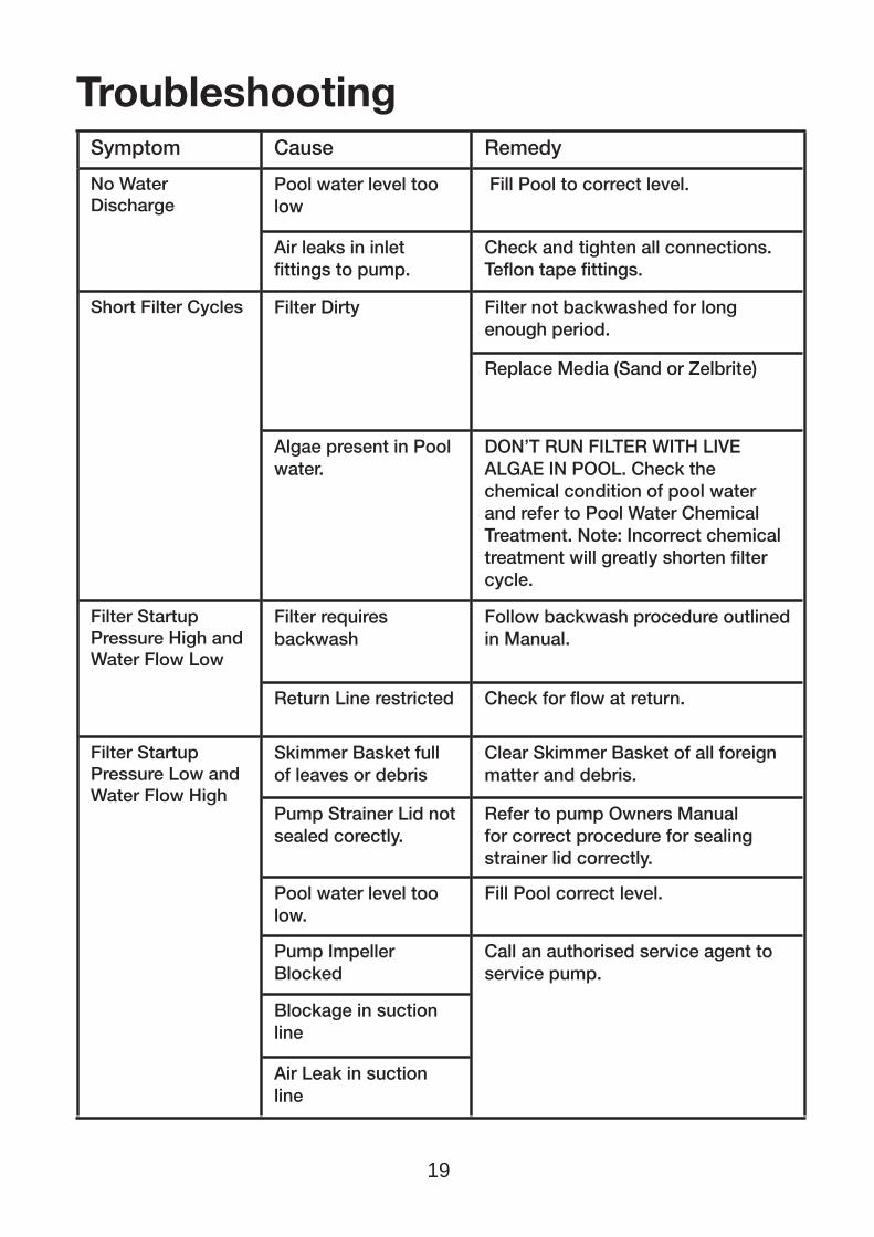
Symptom Cause Remedy
No Water Discharge
Pool water level too low
Fill Pool to correct level.
Air leaks in inlet fi ttings to pump.
Check and tighten all connections. Tefl on tape fi ttings.
Short Filter Cycles Filter Dirty Filter not backwashed for long enough period.
Replace Media (Sand or Zelbrite)
Algae present in Pool water.
DON’T RUN FILTER WITH LIVE ALGAE IN POOL. Check the chemical condition of pool water and refer to Pool Water Chemical Treatment. Note: Incorrect chemical treatment will greatly shorten fi lter cycle.
Filter Startup Pressure High and Water Flow Low
Filter requires backwash
Follow backwash procedure outlined in Manual.
Return Line restricted Check for fl ow at return.
Filter Startup Pressure Low and Water Flow High
Skimmer Basket full of leaves or debris
Clear Skimmer Basket of all foreign matter and debris.
Pump Strainer Lid not sealed corectly.
Refer to pump Owners Manual for correct procedure for sealing strainer lid correctly.
Pool water level too low.
Fill Pool correct level.
Pump Impeller Blocked
Call an authorised service agent to service pump.
Blockage in suction line
Air Leak in suction line
Troubleshooting

20
Leaking From Filter Tank Joint
Tank o-ring dirty Call an authorised service agent to service pump.
o-ring incorrectly fi tted
o-ring damaged (pinched)
Clamp Band not correctly fi tted
Should problems persist, contact your nearest Pentair Water Service Agent.

21
Pentair Water Product WarrantyPentair Water warrants that, when this product is used for the purpose it was designed, is correctly housed and vented against weather, vermin, dust etc., that it will be free of material and manufacturing defects at the time of the original purchase.This warranty is limited to the cost of the product and does not cover third party costs including the costs of electricians, plumbers, etc. unless authorised by Pentair Water.
TERMS AND CONDITIONS APPLICABLE INTERNATIONALLYHow long the warranty is effective Internationally
1) This Pentair Water product is warranted for 12 months for all parts from the date of the fi rst consumer purchase. Should any parts fail as a result of such defects within the specifi ed period, the part will be replaced free of charge. (This does not include travel charges, removal and reinstallation charges.)
TERMS AND CONDITIONS APPLICABLE IN AUSTRALIA ANDNEW ZEALAND
1) YOU SHOULD CAREFULLY READ THE INSTRUCTIONS SUPPLIED PRIOR TO USING THIS PENTAIR WATER PRODUCT. This product is to be installed and operated in accordance with the instructions provided. This warranty will not apply if it is used in a manner other than in accordance with the instructions.What the warranty covers:
Pentair Water warrants its products to be free of defects in material and workmanship during the warranty period. If a product proves to be defective in material or workmanship during the warranty period, then Pentair Water will, at its sole option repair or replace the product with a like product. Replacement product or parts may include re-manufactured or refurbished parts or components.
How long the warranty is effective:
1) This Pentair Water tank is warranted for 10 years (Multi-port Valve and laterals 12 months) from the date of the fi rst consumer purchase.
2) Infi eld service by an authorised Pentair Water Service Agent will be free of charge for the fi rst 12 month period from date of the fi rst consumer purchase when unit is found to have failed due to defective workmanship or material supplied by Pentair Water Australia. Infi eld Service outside this period (fi rst 12 months) will incur a travel, removal & reinstallation fee payable by customer.
3) Where this Pentair Water product is sold for commercial application as defi ned in the relevant Trade Practices and Consumer Protection legislation the warranty shall be for a period of six months from the date of purchase by the end user.
Who the warranty protects:This warranty is valid only for the consumer purchaser.
What the warranty does not cover:
1) Damage, deterioration or malfunction resulting from: a) accident, misuse, negligence, fi re, water, lightning, or other acts of nature, unauthorised product
modifi cation or failure to follow instructions supplied with the product; b) repair or attempted repair by anyone not authorised by Pentair Water; c) any damage to the product due to shipment; d) removal or installation of the product; e) causes external to the product such as electric power fl uctuations or failure; f) use of supplies or parts not meeting Pentair Water specifi cations; g) normal wear and tear;

22
h) water ingression or exposure to abnormal corrosive conditions or “run dry” conditions; i) any other cause which does not relate to a product defect.2) Damage caused to the product as a consequence of use of another manufacturer’s product used in
conjunction with Pentair Water and affi liate companies.3) Ingress of insects into the unit causing electrical malfunction is not warranted, care should be taken
to avoid this occurrence.
Spare Parts:
Spare parts are usually stocked for a reasonable period of time following last production.
Pentair Water does not warrant that spare parts will be made available for the whole of the reasonable period and reserves its right to cease supplying spare parts or providing facilities for repair of spare parts in circumstances which are beyond its control including the requirement to remove spare parts from sale as a consequence of changes in the law or otherwise as it deems fi t.
How to get service:
In Australia please contact 1800 664 266 In New Zealand please contact 0800 664 269 Claims under this warranty must give evidence of date of purchase, model and serial number of the product and the claimants name, address and telephone number.
1) To obtain warranted service, you will be required to provide to either Pentair Water state offi ce or recommended service agent:-
a) the product; b) confi rmation in writing specifying the nature of your claim; c) proof providing date of original purchase; d) full contact details including name and address; e) the serial number of the product if any.2) Warranty service work will be denied or suspended, on equipment not readily accessible to service
personnel, that is products that are behind barriers, tiled or bricked in, installed in roofs or second story external walls including inaccessible power points.
3) Any service of any product which is found to be faulty due to abuse, fair wear & tear, misuse or improper installation will be charged to the owner at the service agents current servicing hourly rate.
Limitation of implied warranties:
THERE ARE NO WARRANTIES, EXPRESSED OR IMPLIED, WHICH EXTEND BEYOND THE DESCRIPTION CONTAINED HEREIN INCLUDING THE IMPLIED WARRANTY OF MERCHANTABILITY AND FITNESS FOR A PARTICULAR PURPOSE.Exclusion of damages:PENTAIR WATER’S LIABILITY IS LIMITED TO THE COST OF REPAIR OR REPLACEMENT OF THE PRODUCT. ONGA SHALL NOT BE LIABLE FOR:1) DAMAGE TO OTHER PROPERTY CAUSED BY ANY DEFECTS IN THE PRODUCT, DAMAGES BASED
UPON INCONVENIENCE, LOSS OF USE OF THE PRODUCT, LOSS OF TIME, LOSS OF PROFITS, LOSS OF BUSINESS OPPORTUNITY, LOSS OF GOODWILL, INTERFERENCE OF BUSINESS RELATIONSHIPS, OR OTHER COMMERCIAL LOSS, EVEN IF ADVISED OF THE POSSIBILITY OF SUCH DAMAGE.
2) ANY OTHER DAMAGES, WHETHER INCIDENTAL, CONSEQUENTIAL OR OTHERWISE.3) ANY CLAIM AGAINST THE CUSTOMER BY ANY OTHER PARTY.
Effective law:
This warranty gives you specifi c legal rights, and you may also have other rights which vary from state to state. Nothing in this warranty limits or restricts, or is intended to derogate from, any right or remedy which the purchaser or ultimate user of the product may have pursuant to Australian state and/or Australian federal consumer protection legislation, New Zealand Sale of Goods Act, Consumer Guarantees Act, Fair Trading Act or any other relevant and applicable New Zealand legislation or authority and where necessary shall so be read and construed.
Pentair Water Product Warranty (Continued)

IMPORTANT
Please attach your sales invoice/docket here as proof of purchase should warranty service
be required.
Please do not return Warranty - Retain for your records.
Purchased From .............................................................................................. ........................
Purchase Date..................................... Serial No.............................. Model No........................
L300123A
0706
Pacific Head Office
Australia Pentair Water Australia Pty LtdNotting Hill Victoria, AustraliaTel: +61 3 9574 4000 Fax: +61 3 9562 7237Email: [email protected]
Pentair Water New Zealand Ltd
Penrose Auckland New ZealandTel: +64 9 579 6254 Fax: +64 9 579 6497Email: [email protected]
Americas Pentair, Inc.
www.pentair.com
Europe Pentair Pumps S.p.Awww.Pentairpumps.it
Asia China
www.pentairwater.com
Indiawww.pentairwater.com
© information contained here-in remains the property of Pentair Water Pty Ltd. Any reproduction, display, publication, modifi cation or distribution is strictly prohibited without the prior written
permission of Pentair Water Pty Ltd.Disclaimer: Every endeavour has been made to publish the correct details in this Owner’s Manual. No responsibility will be taken for errors, omissions or changes in product specifi cations. Pentair
Water reserves the right to change specifi cations